

Page 1

For GPD 515/G5
Adjustable Frequency Drives
DIGITAL REFERENCE CARD (DI-16H2)
MODEL DS016
Before installing this option, a TECHNICALLY QUALIFIED INDIVIDUAL, who is familiar with this type of
equipment and hazards involved, should READ this ENTIRE INSTRUCTION SHEET.
IMPORTANT
This option may have been installed by the factory. However, certain steps can
only be completed at the installation site. Therefore, review and then perform
those steps which complete the installation process.
INTRODUCTION
When installed, this option allows the user to interface a 16-bit digital speed reference to the GPD 515/G5. This
reference can be binary, BCD(Hz) or BCD(%), with SIGN and SET (read) inputs. (Refer to the GPD515/G5
technical manual description of parameter F3-01.)
CAUTION
THIS OPTION CONTAINS CMOS IC CHIPS (ELECTROSTATIC
SENSITIVE DEVICES). PERSONNEL SHOULD BE GROUNDED
BEFORE REMOVING CONTENTS FROM THE CARTON AND
INSTALLING INTO THE EQUIPMENT.
INSTALLATION
1. Disconnect all electrical power to drive.
2. Remove drive front cover. Check that CHARGE indicator lamp inside drive is off.
3. Verify voltage has been disconnected by using a voltmeter to check for voltage at incoming power terminals
(L1, L2, L3).
WARNING
HAZARDOUS VOLTAGE CAN CAUSE SEVERE INJURY OR
DEATH. LOCK ALL POWER SOURCES FEEDING DRIVE IN
"OFF" POSITION.
4. See Figure 2. Install the option on the Main Control Board, 1PCB, and ensure 2CN is properly connected.
Make sure Electrostatic procedure is followed.
Yaskawa Electric America, Inc-www.drives.com
02Y00025-0400 Page 1 OF 5
REL. 05/21/96
Page 2
DIGITAL REFERENCE CARD
(DI-16H2) MODEL DS016
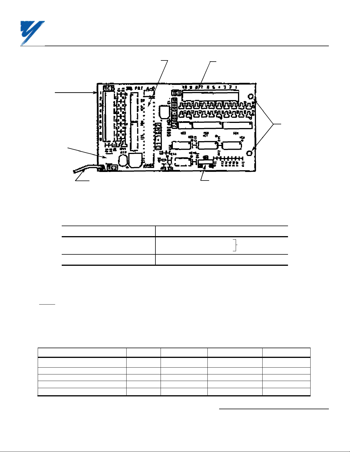
Terminal
block TC2
Terminal TC3
(for connecting
shielded
sheath)
Connector (on back side of card)
to Control Board (2CN)
Grounding lead wire (connects to
terminal 12 on Control Board)
Figure 1. Digital Reference Card DI-16H2
Table 1. Specifications of DI-16H2 Card
Terminal
block TC1
2 mounting
holes
(0.16 in. dia.)
Switch S1
(for selecting input data configuration)
Parameter Value
Input Data Signal Binary 16 Bit/BCD 4 digits
Binary 12 bits/BCD 3 digits
SIGN and SET Signal Voltage +24V
Selected by swtich S1
Control voltage input (from GPD 515/G5): 24V (isolated)
5. Connect the grounding lead wire from the DI-16H2 card to terminal 12 on the Control Board.
6. Wiring. See Figure 3 and Tables 2 & 3 for Digital Reference Card (DI-16H2) connections. Connect digital
input signals to terminal blocks TC1 and TC2. Route wires from the GPD 515/G5 and connect to the peripheral
device(s). Refer to "Electrical Installation" in the GPD 515/G5 technical manual for further information on use of
shielded cable.
Table 2. Applicable Wire Sizes For TC1 and TC2
Wire Type mm
Thin twisted wire 1 16 12 125
Solid wire 1.5 16 12 125
UL —— 22-16 10 300
CSA —— 28-16 10 300
CSA —— 28-16 10 150
2
AWG Current (Amps) VAC
Yaskawa Electric America, Inc-www.drives.com
02Y00025-0400 Page 2 OF 5
REL. 05/21/96
Page 3

DIGITAL REFERENCE CARD
(DI-16H2) MODEL DS016
DI-16H2
Figure 2. Installation of Digital Reference Card (DI-16H2) in GPD 515/G5
Table 3. Terminal Functions of DI-16H2
Terminal Pin Function
Block No. Binary Input BCD Input Notes
1 2
2 2
3 2
TC1 4 2
5 2
6 2
7 2
8 2
9 2
10 2
1 2
2 2
3 2
4 2
TC2 5 2
6 2
7 SIGN signal — SIGN signal: "Off" = Forward direction command
8 SET (read) signal * "On" = Reverse direction command
9 Frequency Ref. Common (0V)
TC3 Shield sheath connection
* SET (read) signal is the signal to read digital speed refenerce data. When
reading, close between TC2-8 and TC2-9 by the timing shown in Figure 4.
0
1
2
3
4
5
6
7
8
9
10
11
12
13
14
15
1
2 — "On" when closed (shorted to 0V at TC2-9);
4 x 10
0
"Off" when open.
8
1 — Binary / BCD selection and input unit is set by
2 GPD 515/G5 parameter F3-01; see Table 4.
4 x 10
1
8 — Terminal screws are metric size M3.
1
2 — Set selection switch S1 according to the input signal
4 x 10
2
configuration being used:
8 S1
1
2 16 12
4 x 10
3
Binary 16 bits/BCD 4 digits Binary 12 bits/BCD 3 digits
8
Yaskawa Electric America, Inc-www.drives.com
02Y00025-0400 Page 3 OF 5
REL. 05/21/96
Page 4

(E)
DIGITAL REFERENCE CARD
(DI-16H2) MODEL DS016
CAUTION
KEEP CONTROL CIRCUIT WIRING SEPARATE FROM MAIN CIRCUIT
INPUT/OUTPUT WIRING.
TO PREVENT ERRONEOUS OPERATION CAUSED BY NOISE INTERFERENCE, USE
SHEILDED CABLE FOR DIGITAL SIGNAL WIRING, AND LIMIT DISTANCE TO
50M (164 FEET) OR LESS.
TRANSISTOR
OPEN COLLECTOR
OUTPUT MAY BE
USED IN PLACE OF
RELAY CONTACT
D0
D1
D2
D3
D4
D5
D6
D7
D8
D9
D10
D11
D12
D13
D14
D15
SIGN
SET
TC1
1
2
3
4
5
6
7
8
9
10
1
2
3
4
5
6
7
8
9
TC2
DI-16H2 CARD
+24V
0.1uF
24K ohm
6.2V
5.1K ohm
TYPICAL INPUT
CIRCUIT
OPTICAL
ISOLATOR
MCCB
0V
L1
L2
L3
GPD
515
2CN 2CN
12
GROUNDING LEAD
WIRE (PART OF
DI-16H2 CARD)
T1
T2
T3
MOTOR
I M
OV
SHIELD
TC3
(E)
Figure 3. Interconnection for Digital Reference Card (DI-16H2) Circuit
Yaskawa Electric America, Inc-www.drives.com
02Y00025-0400 Page 4 OF 5
REL. 05/21/96
Page 5

Digital Reference Data
(Terminals TC1-1 to -10,
TC2-1 to -6, and SIGN
signal, Terminal TC2-7)
DIGITAL REFERENCE CARD
(DI-16H2) MODEL DS016
SET (read) signal
(Terminal TC2-8)
More
than
5ms
More than 40ms
More
than
5ms
Figure 4. Timing of Reference Input
IMPORTANT
The DI-16H2 input circuits can receive output of relay contacts or transistor (open collector).
– Use relays with highly reliable contacts (for very small current) with a capacity of 30VDC or more and rated
current of 100mA or higher.
– Use transistor (open collector) with rated voltage of 35VDC or more and rated current of 30mA or higher.
7. Adjustments. There are no adjustments to be made on the Digital Speed Reference option; however, the GPD
515/G5 will have to be reprogrammed for the input requirement of the digital reference. See Table 4, and refer to the
Technical Manual description of parameter b1-01 (Reference Selection).
IMPORTANT
For the Digital Reference circuit to function properly, GPD 515/G5 parameter b1-01 must be set to " 3 " (input to DI16H2 replaces auto speed reference signal).
8. Reinstall and secure drive cover.
9. Place this instruction sheet with the GPD 515/G5 technical manual.
THIS COMPLETES INSTALLATION OF THIS OPTION.
Table 4. F3-01 – Setting Unit and Range
F3-01 Set Value Setting Unit Setting Range
0 BCD 1% 0 - 159 %
1 BCD 0.1% 0.0 - 15.9 %
2 BCD 0.01% 0.00 - 1.59 %
3 BCD 1Hz 0 - 159 Hz
4 BCD 0.1Hz 0.0 - 15.9 Hz
5 or 6 BCD 0.01Hz 0.00 - 1.59 Hz
7 Binary 255/100% 0 - Max. Output Freq.
Yaskawa Electric America, Inc-www.drives.com
02Y00025-0400 Page 5 OF 5
REL. 05/21/96
 Loading...