

Page 1

ACサーボパック
DC電源入力Σ-Vシリーズ
安全上のご注意
形式:SGDV-EA
製品を安全にお使い頂くために,本書を必ずお読みください。
また,本書をお手元に保管していただくとともに,最終的に本製品をご使用になる
ユーザー様のお手元に確実に届けられるよう,お取り計らい願います。
AC SERVOPACK
DC Power Input Σ-V Series
SAFETY PRECAUTIONS
Type: SGDV-EA
To properly use the product, read this manual thoroughly and retain
for easy reference, inspection, and maintenance. Ensure the end
user receives this manual.
MANUAL NO. TOBP C710829 06D
Page 2

Copyright © 2011 YASKAWA ELECTRIC CORPORATION
All rights reserved. No part of this publication may be reproduced, stored in a
retrieval system, or transmitted, in any form, or by any means, mechanical, electronic, photocopying, recording, or otherwise, without the prior written permission
of Yaskawa. No patent liability is assumed with respect to the use of the information contained herein. Moreover, because Yaskawa is constantly striving to
improve its high-quality products, the information contained in this manual is subject to change without notice. Every precaution has been taken in the preparation
of this manual. Nevertheless, Yaskawa assumes no responsibility for errors or
omissions. Neither is any liability assumed for damages resulting from the use of
the information contained in this publication.
Page 3

General Precautions
• The drawings presented in this manual are sometimes shown
without covers or protective guards. Always replace the cover or
protective guard as specified first, and then operate the products
in accordance with the manual.
• The drawings presented in this manual are typical examples and
may not match the product you received.
• This manual is subject to change due to product improvement,
specification modification, and manual improvement. When this
manual is revised, the manual code is updated and the new manual is published as a next edition. The edition number appears on
the front and back covers.
• Yaskawa will not take responsibility for the results of unauthorized modifications of this product. Yaskawa shall not be liable for
any damages or troubles resulting from unauthorized modification.
Safety Information
The following conventions are used to indicate precautions in this manual.
Failure to heed precautions provided in this manual can result in serious or
possibly even fatal injury or damage to the products or to related equipment
and systems.
WARNING
CAUTION
PROHIBITED
MANDATORY
Indicates precautions that, if not heeded, could possibly result in loss of life or serious injury.
Indicates precautions that, if not heeded, could result
in relatively serious or minor injury, damage to the
product, or faulty operation.
In some situations, the precautions indicated could
have serious consequences if not heeded.
Indicates prohibited actions that must not be performed. For example, this symbol would be used to in-
dicate that fire is prohibited as follows: .
Indicates compulsory actions that must be performed.
For example, this symbol would be used as follows to
indicate that grounding is compulsory: .
E-1
Page 4

Notes for Safe Operation
WARNING
• Never touch any rotating servomotor parts during operation.
Failure to observe this warning may result in injury.
• Before starting operation with a machine connected, make
sure that an emergency stop can be applied at any time.
Failure to observe this warning may result in injury or damage to
the equipment.
• Never touch the inside of the SERVOPACKs.
Failure to observe this warning may result in electric shock.
• Immediately after the power is turned OFF or after a voltage
resistance test, do not touch terminals.
Residual voltage may cause electric shock.
• Follow the procedures and instructions provided in the manuals for the products being used in the trial operation.
Failure to do so may result not only in faulty operation and damage to equipment, but also in personal injury.
• The multiturn limit value need not be changed except for
special applications.
Changing it inappropriately or unintentionally can be dangerous.
• If the Multiturn Limit Disagreement alarm occurs, check the
setting of parameter Pn205 in the SERVOPACK to be sure
that it is correct.
If Fn013 is executed when an incorrect value is set in Pn205, an
incorrect value will be set in the encoder. The alarm will disappear
even if an incorrect value is set, but incorrect positions will be
detected, resulting in a dangerous situation where the machine will
move to unexpected positions.
• Do not remove the cables or connectors from the SERVOPACK while the power is ON.
Failure to observe this warning may result in electric shock.
• Do not damage, pull, exert excessive force on, or place
heavy objects on the cables.
Failure to observe this warning may result in electric shock, stopping operation of the product, or fire.
E-2
Page 5

WARNING
• Do not modify the product.
Failure to observe this warning may result in injury, damage to the
equipment, or fire.
• Provide appropriate braking devices on the machine side to
ensure safety. The holding brake on a servomotor with a
brake is not a braking device for ensuring safety.
Failure to observe this warning may result in injury.
• Do not come close to the machine immediately after resetting an instantaneous power interruption to avoid an unexpected restart. Take appropriate measures to ensure safety
against an unexpected restart.
Failure to observe this warning may result in injury.
• Connect the ground terminal according to local electrical
codes (100 Ω or less).
Improper grounding may result in electric shock or fire.
• Installation, disassembly, or repair must be performed only
by authorized personnel.
Failure to observe this warning may result in electric shock or
injury.
E-3
Page 6
Storage and Transportation
CAUTION
• Do not store or install the product in the following locations.
Failure to observe this caution may result in fire, electric shock, or damage to the equipment.
• Locations subject to direct sunlight
• Locations subject to temperatures outside the range specified in the
storage/installation temperature conditions
• Locations subject to humidity outside the range specified in the storage/installation humidity conditions
• Locations subject to condensation as the result of extreme changes in
temperature
• Locations subject to corrosive or flammable gases
• Locations subject to dust, salts, or iron dust
• Locations subject to exposure to water, oil, or chemicals
• Locations subject to shock or vibration
• Do not hold the product by the cables, motor shaft, or encoder
while transporting it.
Failure to observe this caution may result in injury or malfunction.
• Do not place any load exceeding the limit specified on the packing box.
Failure to observe this caution may result in injury or malfunction.
• If disinfectants or insecticides must be used to treat packing
materials such as wooden frames, pallets, or plywood, the packing materials must be treated before the product is packaged,
and methods other than fumigation must be used.
Example: Heat treatment, where materials are kiln-dried to a
If the electronic products, which include stand-alone products and products installed in machines, are packed with fumigated wooden materials, the electrical components may be greatly damaged by the gases or
fumes resulting from the fumigation process. In particular, disinfectants
containing halogen, which includes chlorine, fluorine, bromine, or
iodine can contribute to the erosion of the capacitors.
core temperature of 56°C for 30 minutes or more.
E-4
Page 7

Installation
CAUTION
• Never use the product in an environment subject to water, corrosive gases, flammable gases, or combustibles.
Failure to observe this caution may result in electric shock or fire.
• Do not step on or place a heavy object on the product.
Failure to observe this caution may result in injury or malfunction.
• Do not cover the inlet or outlet ports and prevent any foreign
objects from entering the product.
Failure to observe this caution may cause internal elements to deteriorate resulting in malfunction or fire.
• Be sure to install the product in the correct direction.
Failure to observe this caution may result in malfunction.
• Provide the specified clearances between the SERVOPACK and
the control panel or with other devices.
Failure to observe this caution may result in fire or malfunction.
• Do not apply any strong impact.
Failure to observe this caution may result in malfunction.
E-5
Page 8
Wiring
CAUTION
• Be sure to wire correctly and securely.
Failure to observe this caution may result in motor overrun, injury, or
malfunction.
• Do not connect a commercial power supply to the U, V, or W terminals for the servomotor connection.
Failure to observe this caution may result in injury or fire.
• Securely connect the main circuit terminals.
Failure to observe this caution may result in fire.
• Do not bundle or run the servomotor main circuit cables together
with the I/O signal cables or the encoder cables in the same duct.
Keep the servomotor main circuit cables separated from the I/O
signal cables and encoder cables by at least 30 cm.
Placing these cables too close to each other may result in malfunction.
• Use shielded twisted-pair cables or screened unshielded twistedpair cables for I/O signal cables and the encoder cables.
• The maximum wiring length is 3 m for I/O signal cables, 50 m for
servomotor main circuit cables and encoder cables, and 10 m for
power supply cables.
• Install the battery in the battery unit of the encoder cable with a
battery unit.
• Voltage remains in the SERVOPACK even after the power supply
is turned OFF. To prevent electric shock, do not touch the input
terminals for the main circuit power supply or those for the control power supply.
Before wiring or inspections, confirm that the SERVOPACK has completely discharged.
• Be sure to observe the following precautions when wiring the
SERVOPACK main circuit terminal blocks.
• Do not turn the SERVOPACK power ON until all wiring, including
the main circuit terminal blocks, has been completed.
• Remove detachable power supply input connectors or motor connec-
tors from the SERVOPACK before wiring.
• Make sure that the wiring for both the main circuit power supply
and control power supply is correct.
Incorrect wiring may cause damage.
E-6
Page 9

CAUTION
• Make sure that the polarity of the input power supply is correct.
Incorrect polarity may cause damage.
• Always use the specified power supply voltage.
An incorrect voltage may result in fire or malfunction.
• Take appropriate measures to ensure that the input power supply
is supplied within the specified voltage fluctuation range.
An incorrect power supply may result in damage to the equipment.
• Install external breakers or other safety devices against short-circuiting in external wiring.
Failure to observe this caution may result in fire.
• Take appropriate and sufficient countermeasures for each form of
potential interference when installing systems in the following
locations.
• Locations subject to static electricity or other forms of noise
• Locations subject to strong electromagnetic fields and magnetic fields
• Locations subject to possible exposure to radioactivity
• Locations close to power supplies
Failure to observe this caution may result in damage to the equipment.
• Do not reverse the polarity of the battery when connecting it.
Failure to observe this caution may damage the battery, the SERVOPACK or servomotor, or cause an explosion.
• Wiring or inspection must be performed by a technical expert.
• Use a 24-VDC or 48-VDC power supply with double insulation or
reinforced insulation.
• Failures caused by incorrect wiring or wrong voltage application
in the brake circuit may damage the equipment or cause an accident resulting in death or injury. Follow the procedures and
instructions for wiring and trial operation precisely as described
in the relevant manual.
• When using a detector or a breaker for leakage current, select
the appropriate one by considering the grounding conditions and
the leakage current of noise filter. For details, contact the manufacturer of the noise filter.
E-7
Page 10

CAUTION
• Motor over-temperature protection is not provided. Motor overtemperature protection shall be provided in the end use when
required by the NEC.
When used with Yaskawa servomotor series SGMMV, external
over-temperature protection is not needed due to the protection
functions in the SERVOPACK and because the motor is rated for
continuous torque from 0 to rated speed.
• Incorrect wiring or incorrect voltage application to the output circuit may cause short-circuit.
The above failures will prevent the holding brake from working, which
may damage the machine or cause an accident resulting in death or
injury.
• Inverting the polarity of the brake signal (/BK), i.e. positive logic,
will prevent the holding brake from working in case of its signal
line disconnection. If this setting is absolutely necessary, check
the operation and confirm that there are no safety problems.
• Provide separate AC/DC power supplies for the main circuits and
for controls.
Failure to observe this caution may result in malfunction.
• Do not connect devices (such as motors or solenoids) that
greatly change the load or devices (such as electromagnetic
switches) that generate surge voltages to the controller power
line.
Failure to observe this caution may result in deterioration of the internal
elements or a blown fuse.
Operation
CAUTION
• Always use the servomotor and SERVOPACK in one of the specified combinations.
Failure to observe this caution may result in fire or malfunction.
• Conduct trial operation on the servomotor alone with the motor
shaft disconnected from the machine to avoid accidents.
Failure to observe this caution may result in injury.
E-8
Page 11

CAUTION
• During trial operation, confirm that the holding brake works correctly. Furthermore, secure system safety against problems such
as signal line disconnection.
• Before starting operation with a machine connected, change the
parameter settings to match the parameters of the machine.
Starting operation without matching the proper settings may cause the
machine to run out of control or malfunction.
• Do not turn the power ON and OFF more than necessary.
Do not use the SERVOPACK for applications that require the power to
turn ON and OFF frequently. Such applications will cause elements in
the SERVOPACK to deteriorate.
As a guideline, at least one hour should be allowed between the power
being turned ON and OFF once actual operation has been started.
• When carrying out JOG operation (Fn002), origin search
(Fn003), or EasyFFT (Fn206), forcing movable machine parts to
stop does not work for forward overtravel or reverse overtravel.
Take necessary precautions.
Failure to observe this caution may result in damage to the equipment.
• When using the servomotor for a vertical axis, install safety
devices to prevent workpieces from falling due to alarms or overtravels. Set the servomotor so that it will stop in the zero clamp
state when overtravel occurs.
Failure to observe this caution may cause workpieces to fall due to
overtravel.
• When not using the tuning-less function, set the correct moment
of inertia ratio (Pn103).
• Setting an incorrect moment of inertia ratio may cause machine vibration.
• Do not touch the SERVOPACK heat sinks or servomotor while
power is ON or soon after the power is turned OFF.
Failure to observe this caution may result in burns due to high temperatures.
• Do not make any extreme adjustments or setting changes of
parameters.
Failure to observe this caution may result in injury or damage to the
equipment due to unstable operation.
E-9
Page 12

CAUTION
• When an alarm occurs, remove the cause, reset the alarm after
confirming safety, and then resume operation.
Failure to observe this caution may result in damage to the equipment,
fire, or injury.
• Do not use the holding brake of the servomotor for braking.
Failure to observe this caution may result in malfunction.
• The servomotor will decelerate to a stop if the main-circuit or the
control-circuit power supply turns OFF during operation without
turning servo OFF.
• An alarm or warning may occur if communications are performed
with the host controller while the SigmaWin+ or Digital Operator
is operating.
If an alarm or warning occurs, it may stop the current process and stop
the system.
Maintenance and Inspection
CAUTION
• Do not disassemble the SERVOPACK and the servomotor.
Failure to observe this caution may result in electric shock or injury.
• Do not attempt to change wiring while the power is ON.
Failure to observe this caution may result in electric shock or injury.
• When replacing the SERVOPACK, resume operation only after
copying the previous SERVOPACK parameters to the new SERVOPACK.
Failure to observe this caution may result in damage to the equipment.
Disposal
CAUTION
• When disposing of the products, treat them as ordinary industrial
waste.
E-10
Page 13

Warranty Information
Free Warranty Period
This product is warranted for twelve months after being delivered to Yaskawa’s
customer or if applicable eighteen months from the date of shipment from
Yaskawa’s factory whichever comes first.
Scope of Warranty
If a Yaskawa product is found to be defective due to Yaskawa workmanship or
materials and the defect occurs during the warranty period, Yaskawa will provide a replacement, repair the defective product, and provide shipping to and
from the site free of charge.
However, if the Yaskawa Authorized Service Center determines that the problem
with a Yaskawa product is not due to defects in Yaskawa’s workmanship or
materials, then the customer will be responsible for the cost of any necessary
repairs.
E-11
Page 14

1 Checking Products on Delivery
A
Check the following items when the DC Power Input Σ-V Series SERVOPACK is delivered.
Items Check Method
Is the delivered SERVOPACK the one
that was ordered?
Is there any damage? Check the overall appearance, and check for
Are there any loose screws? Check screws for looseness using a screw-
If any of the above items are faulty or incorrect, contact your Yaskawa sales
representative or the dealer from whom you purchased the products.
1.1 Nameplate
Check the model numbers marked on the
nameplates of the SERVOPACK. Check the
accessories as well.
damage or scratches that may have occurred
during shipping.
driver.
pplicable
power supply
Serial number
/#&'+0,#2#0
5744170&+0)
#+4
6'/2'4#674'
SERVOPACK type
Rated output current
SERVOPACK nameplate
E-12
Page 15

2 Installation
2 Installation
Observe the Installation instructions in DC Power Input Σ-V Series User’s
Manual Setup Rotational Motor (SIEP S800000 80).
For installation sites, use proper care with the following notes.
Situation Notes on Installation
When installed in a control
panel
When installed near a heating unit
When installed near a
source of vibration
When installed in a place receiving corrosive gases
Others • Avoid installation in a hot and humid place or where
• Design the control panel size, unit layout, and cooling method so that the surrounding air temperature
of the SERVOPACK does not exceed 55°C.
• When installing multiple SERVOPACKs side by
side in a control panel, install cooling fans and provide sufficient space around each SERVOPACK to
allow cooling by fan and natural convection.
Suppress radiation heat from the heating unit and a
temperature rise caused by convection so that the surrounding air temperature of the SERVOPACK does
not exceed 55°C.
Install a vibration isolator underneath the SERVOPACK to prevent it from receiving vibration.
Corrosive gases do not immediately affect the SERVOPACK but will eventually cause SERVOPACK or
contactor-related devices to malfunction. Take appropriate action to protect against corrosive gases.
excessive dust or iron powder is present in the air.
• Be sure there is no condensation or freezing.
• Keep the surrounding air temperature 45°C or less
to ensure long-term reliability.
E-13
Page 16

3 Wiring
3.1 Input Power Supply, Molded-case Circuit Breaker, and Fuse
Use input power supplies that meet the following conditions.
• The main circuit power supply must be a 24-VDC or a 48-VDC power
supply.
• The control circuit power supply must be a 24-VDC power supply.
• The main circuit power supply and the control power supply must be two
separate input power supplies.
• Power supplies must have double or reinforced insulation that conforms
to safety standards.
• Current limiting function is required for AC/DC converter which is used
for main circuit power supply. The current limiting specification must be
50A or less to prevent short-circuit current exceeds 50A under short circuit condition.
• External branch circuit protection must be provided in accordance with
the National Electrical Code and local codes.
When choosing molded-case circuit breakers and fuses for input power supplies on the AC side, confirm the specifications of the input power supplies
and refer to this table.
Also, choose molded-case circuit breakers and fuses that meet the following
cutoff characteristics.
Cutoff characteristics (25°C): ⋅300% of the rated load input current, five
SERVO-
PAC K
Model
SGDV-
1R7E
2R9E
* 1. Values with instantaneous maximum load.
* 2. Values with rated load.
Main
Circuit
Power
Supply
DC
24 V
DC
48 V
DC
24 V
DC
48 V
Max.
Applica-
ble
Servo-
motor
Capacity
[W]
11
30
seconds min.
⋅Does not cut off at the inrush current value
of the power supply.
Power
Supply
Capacity
SERVO-
PAC K
Input Current Capacity
Main Circuit
per
Continu-
Instan-
ous
Rated
[A]
2.0 5.5
E-14
taneous
Max.
[A]
*1
[W]
108
169 1.0 4.5
165 3.5 8.5
411 2.0 10.5
Con-
trol
Cir-
*2
cuit
[A]
0.3 250 600 240 480
Rated Voltage
Fuse
[V]
100
V
400
200
V
V
MCCB
100
V
200
V
[V]
400
V
Page 17

3 Wiring
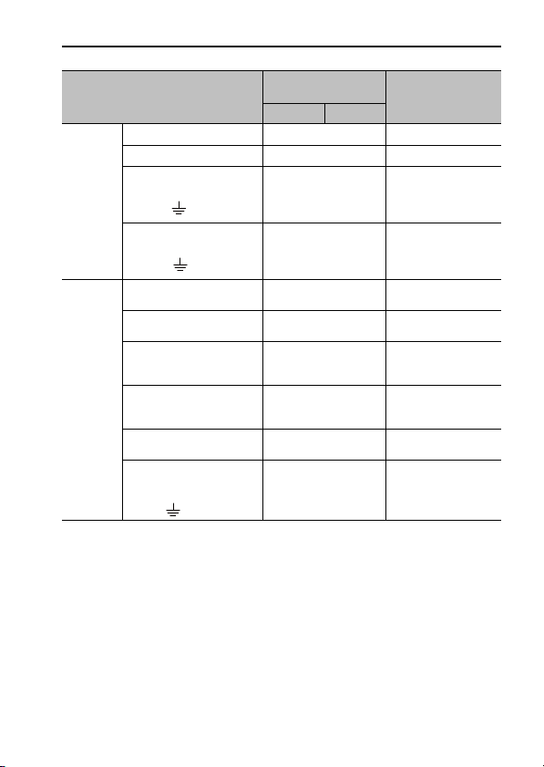
3.2 Names and Functions of Main Circuit Terminals
CN4
CN3
Analog Voltage Models/
Pulse Train Models
Connec-
tor
Te rminal
Sym-
bols
CN3 L1 6 Main circuit input ter-
L2 3 Main circuit input ter-
C1 5 Control power input
C2 4 Control power input
Pin
No.
CN4
CN3
M-II Models M-III Models
Name Description
minal (+)
minal (-)
terminal (+)
terminal (-)
1, 2 Ground terminal Connect to the ground ter-
CN4 U 1 Servomotor connection
V 2 Servomotor connection
W 3 Servomotor connection
terminal (phase U)
terminal (phase V)
terminal (phase W)
4 Ground terminal Connect to the ground ter-
E-15
CN4
CN3
24 VDC ± 15% or
48 VDC ± 15%
24 VDC ± 15%
minal of the power supply.
Connect to the servomotor.
minal of the servomotor.
Page 18

3.3 SERVOPACK Main Circuit Cable
Use the following cables for main circuit of the SERVOPACK. These cables
are manufactured by YASKAWA Controls Co., Ltd.
Cable
For power
supply
For
servomotor
main
circuit
If you make cables by yourself, read the following items.
Terminal
Symbols
L1, L2,
C1, C2,
U, V,
W,
• Wire sizes are selected for three cables per bundle
at 40°C surrounding air temperature with the rated
current.
• Use the withstand voltage wires (for 100 V or
more)
• Use the wires whose outside diameter of insulator
is 1.85 mm or less.
• If cables are bundled in PVC or metal ducts, take
into account the reduction of the allowable current.
• Use a heat-resistant wire under high surrounding
air or panel temperatures.
• The length of cables for power supply is 10 m
max., and the length of cables for servomotor main
circuit is 50 m max.
SERVOPACK Model: SGDV-
1R7E 2R9E
JZSP-CF1G00--E
JZSP-CF1M00--E
(For servomotors without brakes)
JZSP-CF1M10--E
(For servomotors with brakes)
JZSP-CF1M20--E
(For servomotors without brakes, flexible type)
JZSP-CF1M30--E
(For servomotors with brakes, flexible type)
E-16
Page 19
Cable
Connector
Contact
CN3 for
power
supply
For main circuit power
supply
(L1, L2, )
For control circuit power
supply
(C1, C2, )
Connector
(SERVOPACK side)
Contact
(SERVOPACK side)
Connector
CN4 for
servomotor
main
circuit
(servomotor side,
without brake)
Connector
(servomotor side, with
brake)
Contact
(servomotor side)
Power line for servomotor main circuit
(U, V, W, brake power
supply, )
* Made by Molex Japan Co., Ltd.
SERVOPACK
Model: SGDV-
1R7E 2R9E
43025-0600
43030-0001
*
*
UL1007, AWG20
UL1007, AWG20
43025-0400
43030-0001
43020-0401
43020-0601
43031-0001
*
*
*
*
*
UL1007, AWG20
3 Wiring
Remarks
6 poles
–
Rated voltage
300 V,
Rated temperature
80°C
Rated voltage
300 V,
Rated temperature
80°C
4 poles
–
4 poles
6 poles
–
Rated voltage
300 V,
Rated temperature
80°C
E-17
Page 20

3.4 Typical Main Circuit Wiring Examples
• Use a molded-case circuit breaker (1QF) or fuse to
protect the servo system.
Always use a molded-case circuit breaker (1QF) or
fuse to protect the servo system from accidents
involving different power system voltages or other
accidents.
• Install a ground fault detector.
The SERVOPACK does not have a built-in protective circuit for grounding.
To configure a safer system, install a ground fault
detector against overloads and short-circuiting, or
install a ground fault detector combined with a
molded-case circuit breaker.
• Do not frequently turn power ON and OFF.
• Frequently turning power ON and OFF causes
elements inside the SERVOPACK to deteriorate. Do not use the servo drive with an application that requires frequently turning power ON
and OFF.
• After the actual operation starts, the allowable
interval for turning power ON and OFF is one
hour or longer.
E-18
Page 21

3 Wiring
The following wiring examples show the DC Power Input Σ-V Series
SGDV SERVOPACK (Analog voltage reference model).
SGDV-ES1A ( = 1R7, 2R9)
1QF
RT
1FLT
Servo
power
supply
ON
Insulated AC/DC
converter for main
circuit power supply
1KM
Insulated AC/DC
converter for control
circuit power supply
1Ry
Servo
power
supply
OFF
(For servo
alarm display)
1PL
1KM
1Ry
SGDV SERVOPACK
CN4
CN3
L1
L2
C1
C2
FG
CN1
U
V
W
8
11
ALM
COM_SG
1Ry
1D
M
ENC
+24 V
0 V
1KM
1QF
: Molded-case circuit breaker
1FLT
: Noise filter
1KM
: Magnetic contactor
(for main power supply)
1SA
E-19
1Ry
: Relay
1PL
: Indicator lamp
1SA
: Surge absorber
1D
: Flywheel diode
Page 22

4 Inspection
4.1 SERVOPACK Inspection
For inspections and maintenance of the SERVOPACK, follow the inspection
procedures in the table below at least once every year.
Item Frequency Procedure Remedy
Exterior At least once
a year
Loose
screws
4.2 SERVOPACK’s Parts Replacement Schedule
The following electric or electronic parts are subject to deterioration over
time. To avoid failure, replace these parts at the frequency indicated.
Refer to the standard replacement period in the following table, contact your
Yaskawa representative. After an examination of the part in question, we
will determine whether the parts should be replaced or not.
The parameters of any SERVOPACKs overhauled by Yaskawa are reset to
the factory settings before shipping. Be sure to confirm that the parameters
are properly set before starting operation.
Part
Smoothing capacitor
(aluminum electrolytic
capacitor)
Check for dust, dirt, and oil
on surfaces.
Check for loose connector
screws.
Standard
Replacement
Period
7 to 8 years • Surrounding Air Temperature:
Clean with compressed air
or cloth.
Tighten any loose screws.
Operating Conditions
Annual average of 30°C
• Load Factor: 80% max.
• Operation Rate: 20 hours/day
max.
E-20
Page 23

5 Compliance with CE Marking
5 Compliance with CE Marking
5.1 Installation Conditions of EMC Directive
To adapt the EMC directives (EN55011 group1 classA, EN61800-3) for a
combination test using servomotors from the Σ-V mini series and SERVOPACKs from the DC power input Σ-V series, a ferrite core or a noise filter
must be used. For details, read the Installation instructions in DC Power
Input Σ-V Series User’s Manual Setup Rotational Motor (SIEP S800000
80).
However, because this product is built-in, check that the following conditions are still met after being installed in the final product.
5.2 Conditions Corresponding to Low Voltage Directive
To adapt SERVOPACKs to the Low Voltage Directive, make sure that the
following environmental conditions are met.
• Pollution degree: 2
• Protection class: IP10
• Altitude: 1000 m max.
E-21
Page 24

6 Installation Conditions of UL Standards
To adapt SERVOPACKs to the UL standards, make sure that the following
conditions are met.
• Pollution degree: 2
• Protection class: IP10
• Altitude: 1000 m max.
• Short Circuit Current Rating (SCCR): 5000 A
Refer to “3.1 Input Power Supply, Molded-case Circuit Breaker, and
Fuse” for details of power supply selection.
• The main circuit power supply and the control power supply must be two
separate input power supplies.
• Power supplies must have double or reinforced insulation that conforms
to safety standards.
E-22
Page 25

7 Overload Characteristics
7 Overload Characteristics
The overload detection level is set under hot start*1 conditions at a servomotor surrounding air temperature of 40°C.
1000
100
10
Detecting time (s)Detecting time (s)
1
SGMMV-B3E, -B5E
0.1
100 150 200 250
Torque reference
(Current)
1000
SGMMV-A1E,-A2E,-A3E
100
10
SGMMV-B9E
*2
(%)
1
100 200 300 400
Torque reference
* 1. A hot start indicates that both the SERVOPACK and the servomotor have run
long enough at the rated load to be thermally saturated.
* 2. The torque reference (current) is indicated as a rate (percentage) in relation to the
rated current where the rated current is 100%.
E-23
(Current)
(%)
*2
Page 26

Revision History
65432
The revision dates and numbers of the revised manuals are given on the bottom
of the back cover.
MANUAL NO. TOBP C710829 06C
Published in Japan May 2012 11-9
Date of
publication
Date of
Publication
October 2014 0 Back
March 2014 0 Back
May 2013 0 Back
September
2012
May 2012 1 3.1 Revision: Values of the power supply
December 2011 0 Preface Revision: Notes of wiring for safe op-
WEB
Rev.
Rev.
No.
No.
cover
cover
cover
0 – Printed version of the user’s manual
Back
cover
7 Revision: Torque reference (percent of
3.1 Addition: Conditions of input power
3.2, 3.4 Addition
6 Addition: Specification of short circuit
Back
cover
2 -1
WEB revision number
Revision number
Date of original publication
Section Revised Content
Revision: Address
Revision: Address
Revision: Address
that is available on the web (web
version: TOBP C710829 06C<2>-1).
Revision: Address
capacity and the input current capacity for the SGDV1R7E SERVOPACKs
rated torque) → Torque reference (current)
eration
supplies
current rating
Revision: Address
Page 27

Date of
1
Publication
November 2011 – Preface Revision: Notes of wiring and opera-
September
2011
WEB
Rev.
No.
– – – First edition
Section Revised Content
Rev.
No.
tion for safe operation
Page 28

AC SERVOPACK
DC Power Input -V Series
SAFETY PRECAUTIONS
IRUMA BUSINESS CENTER (SOLUTION CENTER)
480, Kamifujisawa, Iruma, Saitama, 358-8555, Japan
Phone 81-4-2962-5151 Fax 81-4-2962-6138
http://www.yaskawa.co.jp
YASKAWA AMERICA, INC.
2121, Norman Drive South, Waukegan, IL 60085, U.S.A.
Phone 1-800-YASKAWA (927-5292) or 1-847-887-7000 Fax 1-847-887-7310
http://www.yaskawa.com
YASKAWA ELÉTRICO DO BRASIL LTDA.
777, Avenida Piraporinha, Diadema, São Paulo, 09950-000, Brasil
Phone 55-11-3585-1100 Fax 55-11-3585-1187
http://www.yaskawa.com.br
YASKAWA EUROPE GmbH
185, Hauptstraβe, Eschborn, 65760, Germany
Phone 49-6196-569-300 Fax 49-6196-569-398
http://www.yaskawa.eu.com
YASKAWA ELECTRIC KOREA CORPORATION
9F, Kyobo Securities Bldg. 26-4, Yeouido-dong, Yeongdeungpo-gu, Seoul, 150-737, Korea
Phone 82-2-784-7844 Fax 82-2-784-8495
http://www.yaskawa.co.kr
YASKAWA ELECTRIC (SINGAPORE) PTE. LTD.
151, Lorong Chuan, #04-02A, New Tech Park, 556741, Singapore
Phone 65-6282-3003 Fax 65-6289-3003
http://www.yaskawa.com.sg
YASKAWA ELECTRIC (THAILAND) CO., LTD.
252/125-126, 27th Floor, Muang Thai-Phatra Tower B, Rachadapisek Road, Huaykwang, Bangkok, 10310, Thailand
Phone 66-2693-2200 Fax 66-2693-4200
http://www.yaskawa.co.th
YASKAWA ELECTRIC (CHINA) CO., LTD.
22F, One Corporate Avenue, No.222, Hubin Road, Shanghai, 200021, China
Phone 86-21-5385-2200 Fax 86-21-5385-3299
http://www.yaskawa.com.cn
YASKAWA ELECTRIC (CHINA) CO., LTD. BEIJING OFFICE
Room 1011, Tower W3 Oriental Plaza, No.1, East Chang An Ave.,
Dong Cheng District, Beijing, 100738, China
Phone 86-10-8518-4086 Fax 86-10-8518-4082
YASKAWA ELECTRIC TAIWAN CORPORATION
9F, 16, Nanking E. Rd., Sec. 3, Taipei, 104, Taiwan
Phone 886-2-2502-5003 Fax 886-2-2505-1280
YASKAWA ELECTRIC CORPORATION
In the event that the end user of this product is to be the military and said product is to be employed in any weapons systems or the manufacture
thereof, the export will fall under the relevant regulations as stipulated in the Foreign Exchange and Foreign Trade Regulations. Therefore, be sure
to follow all procedures and submit all relevant documentation according to any and all rules, regulations and laws that may apply.
Specifications are subject to change without notice for ongoing product modifications and improvements.
© 2011-2014 YASKAWA ELECTRIC CORPORATION. All rights reserved.
MANUAL NO. TOBP C710829 06D
Published in Japan October 2014 11-9
14-9-10
Original instructions
6 -0
Page 29

한국 전파법에 관한 주의사항
韓国電波法に関連する注意事項
Precautions for Korean Radio Waves Act
针对韩国电波法的注意事项
사용자 안내문
기종별 사용자 안내문
A급 기기
( 업무용 방송
통신기 자재 )
이 기기는 업무용 (A 급 ) 전자파 적합 기기로서 판매자
또는 , 사용자는 이 점을 주의하시기 바라며 , 가정외의
지역에서 사용하는 것을 목적으로 합니다 .
 Loading...