

Page 1
YASKAWA AC Drive -V1000
Compact Vector Control Drive
Quick Start Guide
Type: CIMR-VU
Models:
To properly use the product, read this manual thoroughly
and retain for easy reference, inspection, and maintenance.
Ensure the end user receives this manual.
Contém manual suplementar em Português.
200 V Class, Three-Phase Input: 0.1 to 18.5 kW
200 V Class, Single-Phase Input: 0.1 to 3.7 kW
400 V Class, Three-Phase Input: 0.2 to 18.5 kW
MANUAL NO. TOEP C710606 14E
Receiving
Mechanical Installation
Electrical Installation
Start-Up Programming &
Operation
Troubleshooting
Specifications
Parameter List
Standards Compliance
1
2
3
4
5
6
7
8
Page 2

This Page Intentionally Blank
Copyright © 2008 YASKAWA ELECTRIC CORPORATION. All rights reserved.
All rights reserved. No part of this publication may be reproduced, stored in a retrieval system,
or transmitted, in any form or by any means, mechanical, electronic, photocopying, recording,
or otherwise, without the prior written permission of Yaskawa. No patent liability is assumed
with respect to the use of the information contained herein. Moreover, because Yaskawa is
constantly striving to improve its high-quality products, the information contained in this
manual is subject to change without notice. Every precaution has been taken in the preparation
of this manual. Yaskawa assumes no responsibility for errors or omissions. Neither is any
liability assumed for damages resulting from the use of the information contained in this
publication.
2
YASKAWA ELECTRIC TOEP C710606 14E YASKAWA AC Drive – V1000 Quick Start Guide
Page 3

Table of Contents
i. PREFACE & GENERAL SAFETY ........................9
i.1 Preface .................................................................. 10
Applicable Documentation ..........................................10
Symbols..................................................................10
Terms and Abbreviations............................................11
i.2 General Safety .......................................................12
Supplemental Safety Information..................................12
Safety Messages ......................................................13
Drive Label Warnings ................................................17
i.3 Application Precautions ........................................18
General Application Precautions ..................................18
Installation Environment .............................................19
Settings ..................................................................19
General Handling......................................................20
Notes on Motor Operation...........................................21
1. RECEIVING .........................................................25
1.1 Model Number and Nameplate Check....................26
Nameplate...............................................................26
1.2 Component Names ................................................29
IP20/Open-Chassis ...................................................29
IP00/Open-Chassis ...................................................31
YASKAWA ELECTRIC
TOEP C710606 14E YASKAWA AC Drive – V1000 Quick Start Guide
3
Page 4

Table of Contents
IP20/NEMA Type 1 Enclosure ...............................................32
Front Views .......................................................................35
2. MECHANICAL INSTALLATION ..................................37
2.1 Mechanical Installation .................................................... 38
Installation Environment .......................................................38
Installation Orientation and Spacing........................................39
Exterior and Mounting Dimensions .........................................42
3. ELECTRICAL INSTALLATION....................................49
3.1 Standard Connection Diagram......................................... 50
3.2 Terminal Block Configuration.......................................... 53
3.3 Protective Covers ............................................................ 54
IP20/Open-Chassis Front and Bottom Cover Removal and
Installation .......................................................................54
IP20/NEMA Type 1 Front and Bottom Cover Removal and
Installation .......................................................................55
IP20/NEMA Type 1 Top Cover Removal and Installation.............57
3.4 Main Circuit Wiring .......................................................... 59
Main Circuit Terminal Functions.............................................59
Wire Gauges and Tightening Torque.......................................59
Main Circuit Terminal Power Supply and Motor Wiring................62
3.5 Control Circuit Wiring...................................................... 65
Control Circuit Terminal Block Functions..................................65
Terminal Configuration.........................................................68
Wiring Procedure................................................................70
3.6 I/O Connections............................................................... 72
Sinking/Sourcing Mode Switch...............................................72
3.7 Main Frequency Reference .............................................. 75
DIP Switch S1 Analog Input Signal Selection............................75
3.8 Wiring Checklist .............................................................. 77
4. START-UP PROGRAMMING & OPERATION ............79
4.1 Using the Digital LED Operator........................................ 80
4
YASKAWA ELECTRIC TOEP C710606 14E YASKAWA AC Drive – V1000 Quick Start Guide
Page 5

Table of Contents
Keys, Displays, and LEDs.....................................................80
LED Screen Displays...........................................................82
LO/RE LED and RUN LED Indications ....................................82
Menu Structure for Digital LED Operator..................................83
4.2 The Drive and Programming Modes ................................ 84
Changing Parameter Settings or Values ..................................84
Switching Between LOCAL and REMOTE................................85
Parameters Available in the Setup Group.................................85
4.3 Start-up Flowcharts ......................................................... 87
Flowchart A: Basic Start-up and Motor Tuning ..........................88
Subchart A1: Simple Motor Setup with Energy Savings or Speed
Search Using V/f Mode.......................................................89
Subchart A2: High Performance Operation Using Open Loop
Vector Motor Control ..........................................................90
Subchart A3: Operation with Permanent Magnet Motors .............91
4.4 Powering Up the Drive..................................................... 92
Powering Up the Drive and Operation Status Display .................92
4.5 Application Selection....................................................... 93
Setting 1: Water Supply Pump Application ...............................93
Setting 2: Conveyor Application .............................................94
Setting 3: Exhaust Fan Application .........................................95
Setting 4: HVAC Fan Application............................................96
Setting 5: Compressor Application..........................................96
Setting 6: Preset 6 ..............................................................97
Notes on Controlling the Brake when Using Application Preset
6 ....................................................................................98
Setting 7: Preset 7 ............................................................ 100
4.6 Basic Drive Setup Adjustments ......................................102
Control Mode Selection: A1-02 ............................................102
Initialize Parameter Values: A1-03........................................ 102
Frequency Reference Source: b1-01..................................... 103
Run Command Input Selection: b1-02................................... 105
Drive Duty Mode and Carrier Frequency Selection: C6-01 and
C6-02............................................................................ 107
Drive Input Voltage Setting: E1-01........................................ 108
4.7 Auto-Tuning....................................................................109
Types of Auto-Tuning ........................................................ 109
YASKAWA ELECTRIC TOEP C710606 14E YASKAWA AC Drive – V1000 Quick Start Guide
5
Page 6

Table of Contents
Before Auto-Tuning the Drive ..............................................109
Auto-Tuning Interruption and Fault Codes.............................. 110
Performing Auto-Tuning .....................................................111
Auto-Tuning Example ........................................................113
Input Data for Auto-Tuning.................................................. 115
4.8 No-Load Operation Test Run ..........................................118
No-Load Operation Test Run............................................... 118
4.9 Test Run with Load Connected.......................................120
Test Run with the Load Connected....................................... 120
4.10 Test Run Checklist .........................................................121
5. TROUBLESHOOTING ...............................................123
5.1 Drive Alarms, Faults, and Errors.....................................124
Types of Alarms, Faults, and Errors...................................... 124
5.2 Fault Detection ...............................................................125
Fault Displays, Causes, and Possible Solutions ...................... 125
5.3 Alarm Detection..............................................................140
Alarm Codes, Causes, and Possible Solutions........................ 140
5.4 Operator Programming Errors........................................143
oPE Codes, Causes, and Possible Solutions .......................... 143
5.5 Auto-Tuning Fault Detection...........................................144
Auto-Tuning Codes, Causes, and Possible Solutions ............... 144
5.6 Diagnosing and Resetting Faults....................................147
Fault Reset Methods ......................................................... 147
6. SPECIFICATIONS......................................................149
6.1 Heavy Duty and Normal Duty Ratings.............................150
6.2 Single/Three-Phase 200 V Class Drive............................151
6.3 Three-Phase 400 V Class Drives.....................................155
7. PARAMETER LIST ....................................................157
7.1 Parameter Table..............................................................158
6
YASKAWA ELECTRIC TOEP C710606 14E YASKAWA AC Drive – V1000 Quick Start Guide
Page 7

Table of Contents
8. STANDARDS COMPLIANCE .................................... 191
8.1 European Standards.......................................................192
CE Low Voltage Directive Compliance .................................. 192
EMC Guidelines Compliance............................................... 194
8.2 UL Standards..................................................................200
UL Standards Compliance .................................................. 200
Drive Motor Overload Protection ..........................................203
8.3 Safe Disable Input Precautions.......................................206
Safe Disable Function Description........................................ 206
Installation ...................................................................... 206
8.4 V1000 - ORIENTAÇÃO BÁSICA ......................................208
INVERSORES - V1000 TERMO DE GARANTIA .....................208
INVERSORES DE FREQUÊNCIA - V1000............................. 208
Revision History ............................................................... 213
YASKAWA ELECTRIC TOEP C710606 14E YASKAWA AC Drive – V1000 Quick Start Guide
7
Page 8

Table of Contents
This Page Intentionally Blank
8
YASKAWA ELECTRIC TOEP C710606 14E YASKAWA AC Drive – V1000 Quick Start Guide
Page 9

Preface & General
Safety
This section provides safety messages pertinent to this product
that, if not heeded, may result in fatality, personal injury, or
equipment damage. Yaskawa is not responsible for the
consequences of ignoring these instructions.
i.1 PREFACE.........................................................10
i.2 GENERAL SAFETY...........................................12
i.3 APPLICATION PRECAUTIONS..........................18
i
YASKAWA ELECTRIC TOEP C710606 14E YASKAWA AC Drive – V1000 Quick Start Guide
9
Page 10

TERMSTERMS
i.1 Preface
i.1 Preface
Yaskawa manufactures products used as components in a wide variety of industrial systems
and equipment. The selection and application of Yaskawa products remain the responsibility
of the equipment manufacturer or end user. Yaskawa accepts no responsibility for the way its
products are incorporated into the final system design. Under no circumstances should any
Yaskawa product be incorporated into any product or design as the exclusive or sole safety
control. Without exception, all controls should be designed to detect faults dynamically and
fail safely under all circumstances. All systems or equipment designed to incorporate a product
manufactured by Yaskawa must be supplied to the end user with appropriate warnings and
instructions as to the safe use and operation of that part. Any warnings provided by Yaskawa
must be promptly provided to the end user. Yaskawa offers an express warranty only as to the
quality of its products in conforming to standards and specifications published in the Yaskawa
manual. NO OTHER WARRANTY, EXPRESSED OR IMPLIED, IS OFFERED. Yaskawa
assumes no liability for any personal injury, property damage, losses, or claims arising from
misapplication of its products.
u
Applicable Documentation
The following manuals are available for V1000 series drives:
V1000 Series AC Drive Quick Start Guide
Read this manual first. This guide is packaged together with the product. It
contains basic information required to install and wire the drive. This guide
provides basic programming and simple setup and adjustment. Refer to the
V1000 Technical Manual for complete descriptions of drive features and
functions.
V1000 Series AC Drive Technical Manual
This manual describes installation, wiring, operation procedures, functions,
troubleshooting, maintenance, and inspections to perform before operation.
u
Symbols
Note: Indicates a supplement or precaution that does not cause drive damage.
Indicates a term or definition used in this manual.
10
YASKAWA ELECTRIC TOEP C710606 14E YASKAWA AC Drive – V1000 Quick Start Guide
Page 11

u
TERMSTERMS
Terms and Abbreviations
• Drive: Yaskawa V1000 Series Drive
• PM motor: Synchronous motor (an abbreviation for IPM motor or SPM
motor)
• IPM motor: SSR1 Series
• SPM motor: SMRA Series SPM Motor
• PG: Pulse Generator
i.1 Preface
YASKAWA ELECTRIC TOEP C710606 14E YASKAWA AC Drive – V1000 Quick Start Guide
11
Page 12
i.2 General Safety
i.2 General Safety
u
Supplemental Safety Information
General Precautions
• The diagrams in this manual may be indicated without covers or safety shields to show details. Restore
covers or shields before operating the drive and run the drive according to the instructions described
in this manual.
• Any illustrations, photographs, or examples used in this manual are provided as examples only and
may not apply to all products to which this manual is applicable.
• The products and specifications described in this manual or the content and presentation of the manual
may be changed without notice to improve the product and/or the manual.
• When ordering a new copy of the manual due to damage or loss, contact your Yaskawa representative
or the nearest Yaskawa sales office and provide the manual number shown on the front cover.
• If nameplate becomes worn or damaged, order a replacement from your Yaskawa representative or
the nearest Yaskawa sales office.
WARNING
Read and understand this manual before installing, operating or servicing this drive. The
drive must be installed according to this manual and local codes.
The following conventions are used to indicate safety messages in this manual. Failure to
heed these messages could result in serious or possibly even fatal injury or damage to the
products or to related equipment and systems.
DANGER
Indicates a hazardous situation, which, if not avoided, will result in death or serious
injury.
WARNING
Indicates a hazardous situation, which, if not avoided, could result in death or serious
injury.
WARNING! will also be indicated by a bold key word embedded in the text followed by an italicized safety
message.
12
YASKAWA ELECTRIC TOEP C710606 14E YASKAWA AC Drive – V1000 Quick Start Guide
Page 13

i.2 General Safety
CAUTION
Indicates a hazardous situation, which, if not avoided, could result in minor or
moderate injury.
CAUTION! will also be indicated by a bold key word embedded in the text followed by an italicized safety
message.
NOTICE
Indicates a property damage message.
NOTICE: will also be indicated by a bold key word embedded in the text followed by an italicized safety
message.
u
Safety Messages
DANGER
Heed the safety messages in this manual.
Failure to comply will result in death or serious injury.
The operating company is responsible for any injuries or equipment damage resulting from
failure to heed the warnings in this manual.
Electrical Shock Hazard
Do not connect or disconnect wiring while the power is on.
Failure to comply will result in death or serious injury.
Before servicing, disconnect all power to the equipment. The internal capacitor remains
charged even after the power supply is turned off. The charge indicator LED will extinguish
when the DC bus voltage is below 50 Vdc. To prevent electric shock, wait at least five
minutes after all indicators are OFF and measure the DC bus voltage level to confirm safe
level.
YASKAWA ELECTRIC TOEP C710606 14E YASKAWA AC Drive – V1000 Quick Start Guide
13
Page 14

i.2 General Safety
WARNING
Sudden Movement Hazard
System may start unexpectedly upon application of power, resulting in death or serious
injury.
Clear all personnel from the drive, motor and machine area before applying power. Secure
covers, couplings, shaft keys and machine loads before applying power to the drive.
When using DriveWorksEZ to create custom programming, the drive I/O terminal
functions change from factory settings and the drive will not perform as outlined in
this manual.
Unpredictable equipment operation may result in death or serious injury.
Take special note of custom I/O programming in the drive before attempting to operate
equipment.
Electrical Shock Hazard
Do not attempt to modify or alter the drive in any way not explained in this manual.
Failure to comply could result in death or serious injury.
Yaskawa is not responsible for any modification of the product made by the user. This
product must not be modified.
Do not allow unqualified personnel to use equipment.
Failure to comply could result in death or serious injury.
Maintenance, inspection, and replacement of parts must be performed only by authorized
personnel familiar with installation, adjustment and maintenance of AC drives.
Do not remove covers or touch circuit boards while the power is on.
Failure to comply could result in death or serious injury.
Fire Hazard
Do not use an improper voltage source.
Failure to comply could result in death or serious injury by fire.
Verify that the rated voltage of the drive matches the voltage of the incoming power supply
before applying power.
14
YASKAWA ELECTRIC TOEP C710606 14E YASKAWA AC Drive – V1000 Quick Start Guide
Page 15
i.2 General Safety
WARNING
Crush Hazard
Do not use this drive in lifting applications without installing external safety circuitry
to prevent accidental dropping of the load.
The drive does not possess built-in load drop protection for lifting applications.
Failure to comply could result in death or serious injury from falling loads.
Install electrical and/or mechanical safety circuit mechanisms independent of drive circuitry.
CAUTION
Crush Hazard
Do not carry the drive by the front cover.
Failure to comply may result in minor or moderate injury from the main body of the drive
falling.
NOTICE
Observe proper electrostatic discharge procedures (ESD) when handling the drive and
circuit boards.
Failure to comply may result in ESD damage to the drive circuitry.
Never connect or disconnect the motor from the drive while the drive is outputting
voltage.
Improper equipment sequencing could result in damage to the drive.
Do not perform a withstand voltage test on any part of the drive.
Failure to comply could result in damage to the sensitive devices within the drive.
Do not operate damaged equipment.
Failure to comply could result in further damage to the equipment.
Do not connect or operate any equipment with visible damage or missing parts.
YASKAWA ELECTRIC TOEP C710606 14E YASKAWA AC Drive – V1000 Quick Start Guide
15
Page 16

i.2 General Safety
NOTICE
Install adequate branch circuit short circuit protection per applicable codes.
Failure to comply could result in damage to the drive.
The drive is suitable for circuits capable of delivering not more than 30,000 RMS
symmetrical Amperes, 240 Vac maximum (200 V Class) and 480 Vac maximum (400 V
Class).
Do not expose the drive to halogen group disinfectants.
Failure to comply may cause damage to the electrical components in the drive.
Do not pack the drive in wooden materials that have been fumigated or sterilized.
Do not sterilize the entire package after the product is packed.
16
YASKAWA ELECTRIC TOEP C710606 14E YASKAWA AC Drive – V1000 Quick Start Guide
Page 17
i.2 General Safety
u
Drive Label Warnings
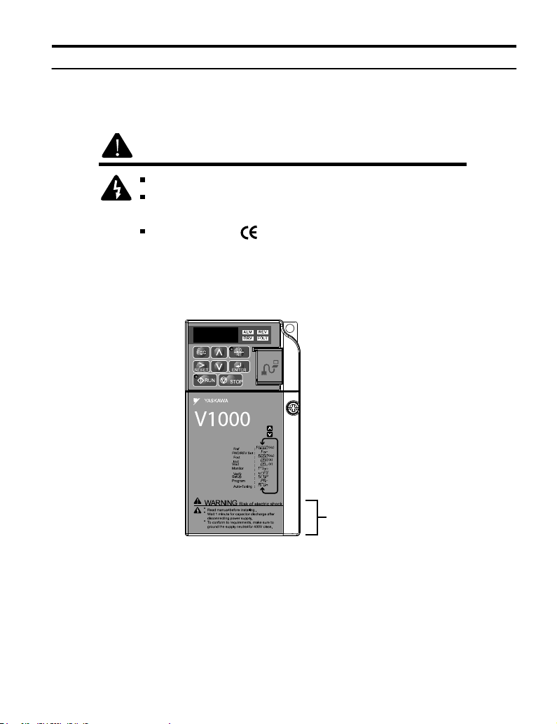
Always heed the warning information listed in Figure i.1 in the position shown in Figure i.
2 .
WARNING
Risk of electric shock.
Read manual before installing.
Wait 5 minutes for capacitor discharge after
disconnecting power supply.
To conform to requirements, make sure
to ground the supply neutral for 400V class.
Figure i.1 Warning Information
Warning
Label
Figure i.2 Warning Information Position
YASKAWA ELECTRIC TOEP C710606 14E YASKAWA AC Drive – V1000 Quick Start Guide
17
Page 18

i.3 Application Precautions
i.3 Application Precautions
u
General Application Precautions
Selecting a Reactor
n
An AC or DC reactor can be used for the following:
• to suppress harmonic current.
• to smooth peak current that results from capacitor switching.
• when the power supply is above 600 kVA.
• when the drive is running from a power supply system with thyristor converters.
Note: A DC reactor is built in to 200 V and 400 V class models with a capacity of 22 kW and higher (HD rating).
4000
Power supply harmonics
reactor required
Power Supply
Capacity (kVA)
600
0
Figure i.3 Installing a Reactor
60 400
Drive Capacity (kVA)
Reactor
unnecessary
Drive Capacity
n
Make sure that the motor rated current is less than the rated nameplate output current of the
drive. When running more than one motor in parallel from a single drive, the drive rated current
should 1.1 times larger than the total motor rated current for all connected motors or nuisance
drive faults may occur.
Starting Torque
n
The overload rating of the drive determines the starting and accelerating characteristics of the
motor. Expect lower running torque than when running the motor from line power. To get
more starting torque, use a larger drive or increase both the motor and drive capacity.
18
YASKAWA ELECTRIC TOEP C710606 14E YASKAWA AC Drive – V1000 Quick Start Guide
Page 19

i.3 Application Precautions
Emergency/Fast Stop
n
During a drive fault condition, a protective circuit is activated and drive output is shut off.
The motor may coast to a stop or attempt to decelerate depending on parameter settings. If
the emergency/fast stop cannot stop the load as fast as desired, a customer-supplied
mechanical brake may be required. Test emergency stop circuitry before putting drive into
operation.
Options
n
The B1, B2, +1, +2, and +3 terminals are used to connect optional power devices. Connect
only devices compatible with the drive.
Repetitive Starting/Stopping
n
Applications with frequent starts and stops often exceed 150% of their rated current values.
Heat stress generated from repetitive high current can shorten the life span of the IGBTs. The
expected lifesaving for the IGBTs is about 8 million start and stop cycles with a 4 kHz carrier
frequency and a 150% peak current.
Yaskawa recommends lowering the carrier frequency, particularly when audible noise is not
a concern. The user can also choose to reduce the load, increase the acceleration and
deceleration times, or switch to a larger drive. This will help keep peak current levels under
150%. Be sure to check the peak current levels when starting and stopping repeatedly during
the initial test run, and make adjustments accordingly.
u
Installation Environment
Enclosure Panels
n
Keep the drive in a clean environment by either selecting an area free of airborne dust, lint,
and oil mist, or install the drive in an enclosure panel. Be sure to leave the required space
between drives to provide for cooling, and that proper measures are taken so that the ambient
temperature remains within allowable limits. Keep flammable materials away from the drive.
If the drive must be used in an area where it is subjected to oil mist and excessive vibration,
protective designs are available. Contact Yaskawa or your Yaskawa agent for details.
Installation Direction
n
The drive should be installed upright as specified in the manual.
u
Settings
Motor Code
n
If using OLV/PM designed for permanent magnet motors (A1-02 = 5), make sure that the
proper motor code is set in parameter E5-01 before performing a trial run.
YASKAWA ELECTRIC TOEP C710606 14E YASKAWA AC Drive – V1000 Quick Start Guide
19
Page 20

i.3 Application Precautions
Upper Limits
n
The drive is capable of running the motor up to 400 Hz. Due to the danger of accidentally
operating the motor at high speed, be sure to set the upper frequency limit. The default setting
for the maximum output frequency is 60 Hz.
DC Injection Braking
n
Motor overheat can result if there is too much current used during DC Injection Braking, or
if the DC Injection Braking time is too long.
Acceleration/Deceleration Times
n
Acceleration and deceleration times are affected by how much torque the motor generates,
the load torque, and the inertia moment ((GD2)/4). Set a longer accel/decel time when Stall
Prevention is enabled. The accel/decel times are lengthened for as long as the Stall Prevention
function is operating. For faster acceleration and deceleration, install a braking option or
increase the capacity of the drive.
u
General Handling
NOTICE: Wiring Check. Never connect the power supply lines to output terminals U/T1, V/T2, or W/T3. Doing
so will destroy the drive. Be sure to perform a final check of all control wiring and other connections before
applying line power. Make sure there are no short circuits on the control terminals (+V, AC, etc.), as this could
damage the drive.
Selecting a Molded Case Circuit Breaker (MCCB) or Ground Fault
n
Circuit Interrupter (GFCI)
Yaskawa recommends installing a GFCI on the line power supply to protect drive wiring and
prevent damage in the event of component failure. An MCCB may also be used if permitted
by the power system.
The GFCI should be designed for use with an AC drive (i.e., protected against harmonics)
MCCB selection depends on the power factor for the drive, determined by the power supply
voltage, output frequency, and load.
Refer to the Peripheral Devices & Options chapter of the Technical Manual for more
information on breaker installation. Note that a larger capacity breaker is needed when using
a fully electromagnetic MCCB, as operation characteristics vary with harmonic current.
Magnetic Contactor (MC) Installation
n
Use an MC to ensure that line power to the drive can be completely shut off when necessary.
The MC should be wired so that it opens when the drive fault output is triggered.
Avoid switching the MC on the power supply side more frequently than once every 30 minutes.
Frequent switching can cause damage to the drive.
20
YASKAWA ELECTRIC TOEP C710606 14E YASKAWA AC Drive – V1000 Quick Start Guide
Page 21

i.3 Application Precautions
Inspection and Maintenance
n
DANGER! Electrical Shock Hazard. Do not connect or disconnect wiring while the power is on. Failure to
comply will result in death or serious injury. Disconnect all power to the drive, wait at least five minutes after
all indicators are OFF, measure the DC bus voltage to confirm safe level, and check for unsafe voltages before
servicing to prevent electrical shock. The internal capacitor remains charged even after the power supply is
turned off. The charge indicator LED will extinguish when the DC bus voltage is below 50 Vdc.
CAUTION! Burn Hazard. Do not touch a hot drive heatsink. Failure to comply could result in minor or moderate
injury. Shut off the power to the drive when replacing the cooling fan. To prevent burns, wait at least 15 minutes
and make sure the heatsink has cooled to a safe level.
WARNING! Electrical Shock Hazard. Wait for at least the time specified on the drive warning label after
opening the load switch on the output side before any inspection or maintenance of permanent magnet (PM)
motors. Failure to comply could result in death or serious injury.
WARNING! Sudden Movement Hazard. Install a switch disconnect between the motor and the drive in
applications where the machine can still rotate even though the drive has fully stopped. Unpredictable
equipment operation may result in death or serious injury.
WARNING! Sudden Movement Hazard. Do not attempt to move a load that could potentially rotate the motor
faster than the maximum allowable r/min when the drive has been shut off. Unpredictable equipment operation
may result in death or serious injury.
NOTICE: Do not open and close the motor disconnect switch while the motor is running, as this may damage
the drive.
NOTICE: If the motor is coasting, make sure the power to the drive is turned on and the drive output has
completely stopped before closing the load switch.
Wiring
n
All wire ends should use ring terminals for UL/cUL compliance. Use only the tools
recommended by the terminal manufacturer for crimping.
Transporting the Drive
n
NOTICE: Prevent the drive from contact with salts, fluorine, bromine, phthalate ester, and other such harmful
chemicals. Never steam clean the drive. Failure to comply may cause damage to the drive components.
u
Notes on Motor Operation
Using a Standard Motor
n
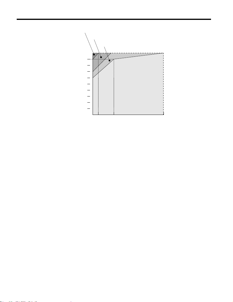
Low Speed Range
The cooling fan of a standard motor is usually designed to sufficiently cool the motor at the
rated speed. As the self-cooling capability of such a motor reduces with the speed, applying
full torque at low speed will possibly damage the motor. To prevent motor damage from
overheat, reduce the load torque as the motor slows. Figure i.4 shows the allowable load
characteristics for a Yaskawa standard motor. A motor designed specifically for operation
with a drive should be used when 100% continuous torque is needed at low speeds.
YASKAWA ELECTRIC TOEP C710606 14E YASKAWA AC Drive – V1000 Quick Start Guide
21
Page 22
i.3 Application Precautions
100
Torque
(%)
25% ED (or 15 min)
40% ED (or 20 min)
60% ED (or 40 min)
90
80
70
60
50
Continuous operation
3 6
Figure i.4 Allowable Load Characteristics for a Yaskawa Motor
20
Frequency (Hz)
60
Insulation Tolerance
Consider motor voltage tolerance levels and motor insulation in applications with an input
voltage of over 440 V or particularly long wiring distances. Contact Yaskawa or your Yaskawa
agent for consultation.
High Speed Operation
Problems may occur with the motor bearings and dynamic balance of the machine when
operating a motor beyond its rated speed. Contact the motor or machine manufacturer.
Torque Characteristics
Torque characteristics differ compared to operating the motor directly from line power. The
user should have a full understanding of the load torque characteristics for the application.
Vibration and Shock
The drive settings allow the user to choose between high carrier PWM control and low carrier
PWM. Selecting high carrier PWM can help reduce motor oscillation.
Take particular caution when using a variable speed drive for an application that is
conventionally run from line power at a constant speed. If mechanical resonance occurs, install
shock-absorbing rubber around the base of the motor and enable the Jump frequency selection
parameter to prevent continuous operation in the resonant frequency range.
22
YASKAWA ELECTRIC TOEP C710606 14E YASKAWA AC Drive – V1000 Quick Start Guide
Page 23

i.3 Application Precautions
Audible Noise
Noise created during run varies by the carrier frequency setting. When using a high carrier
frequency, audible noise from the motor is comparable to the motor noise generated when
running from line power. Operating above the rated r/min, however, can create unpleasant
motor noise.
Using a Synchronous Motor
n
• Synchronous motors cannot be started directly from line power. Applications requiring line
power to start should use an induction motor with the drive.
• A single drive is not capable of running multiple synchronous motors at the same time. Use
a standard induction motor for such setups.
• At start, a synchronous motor may rotate slightly in the opposite direction of the Run
command depending on parameter settings and motor type.
• The amount of starting torque that can be generated differs by each control mode and by
the type of motor being used. Set up the motor with the drive after verifying the starting
torque, allowable load characteristics, impact load tolerance, and speed control range.
Contact Yaskawa or your Yaskawa agent if you plan to use a motor that does not fall within
these specifications.
• Braking Torque: In Open Loop Vector Control for PM motors, braking torque is less than
125% when running between 20% to 100% speed, even with a braking resistor. Braking
torque drops to less than half when running at less than 20% speed.
• Load Inertia: In Open Loop Vector Control for PM motors, the allowable load inertia
moment is approximately 50 times higher than the motor inertia moment or less. Contact
Yaskawa or your Yaskawa agent concerning applications with a larger inertia moment.
• Holding Brake: When using a holding brake in Open Loop Vector Control for PM motors,
release the brake prior to starting the motor. Failure to set the proper timing can result in
speed loss. Not for use with conveyor, transport, or hoist type applications.
• Restarting a Coasting Motor: To restart a coasting motor rotating at over 200 Hz while in
the V/f control mode, use the Short Circuit Braking function to first bring the motor to a
stop. Short Circuit Braking requires a special braking resistor. Contact Yaskawa or your
Yaskawa agent for details.
Speed Search can be used to restart a coasting motor rotating slower than 200 Hz. If the
motor cable is relatively long, however, the motor should instead be stopped using Short
Circuit Braking, which forces the motor to stop by creating a short-circuit in the motor
windings.
YASKAWA ELECTRIC TOEP C710606 14E YASKAWA AC Drive – V1000 Quick Start Guide
23
Page 24

i.3 Application Precautions
Applications with Specialized Motors
n
Multi-Pole Motor
Because the rated current will differ from a standard motor, be sure to check the maximum
current when selecting a drive. Always stop the motor before switching between the number
of motor poles. If a regen overvoltage (oV) fault occurs or if overcurrent protection (oC) is
triggered, the motor will coast to stop.
Submersible Motor
Because motor rated current is greater than a standard motor, select the drive capacity
accordingly. Be sure to use a large enough gauge motor cable to avoid decreasing the
maximum torque level on account of voltage drop caused by a long motor cable.
Explosion-Proof Motor
Both the motor and drive need to be tested together to be certified as explosion-proof. The
drive is not designed for explosion proof areas.
Furthermore, if an encoder is attached to an explosion-proof motor make sure the encoder is
also explosion-proof. Use an insulating signal converter for connecting the encoder signal
lines to the drives speed feedback option card.
Geared Motor
To avoid gear damage when operating at low speeds or very high speeds, make sure that both
the gear and lubricant are rated for the desired speed range. Consult with the manufacturer for
applications that require operation outside the rated speed range of the motor or gear box.
Single-Phase Motor
Variable speed AC drives are not designed for operation with single phase motors. Using
capacitors to start the motor causes excessive current to flow and can damage drive
components. A split-phase start or a repulsion start can end up burning out the starter coils
because the internal centrifugal switch is not activated. The drive is for use with 3-phase
motors only.
Motor with Brake
Caution should be taken when using a drive to operate a motor with a built-in holding brake.
If the brake is connected to the output side of the drive, it may not release at start due to low
voltage levels. A separate power supply should be installed for the motor brake. Motors with
a built-in brake tend to generate a fair amount of noise when running at low speeds.
Power Driven Machinery (decelerators, belts, chains, etc.)
n
Continuous operation at low speeds wears on the lubricating material used in gear box type
systems to accelerate and decelerate power driven machinery. Caution should also be taken
when operating at speeds above the rated machine speed due to noise and shortened
performance life.
24
YASKAWA ELECTRIC TOEP C710606 14E YASKAWA AC Drive – V1000 Quick Start Guide
Page 25

1
Receiving
This chapter describes the proper inspections to perform after
receiving the drive and illustrates the different enclosure types
and components.
1.1 MODEL NUMBER AND NAMEPLATE CHECK
.........................................................................26
1.2 COMPONENT NAMES.......................................29
YASKAWA ELECTRIC TOEP C710606 14E YASKAWA AC Drive – V1000 Quick Start Guide
25
Page 26
1.1 Model Number and Nameplate Check
1.1 Model Number and Nameplate Check
Please perform the following tasks after receiving the drive:
• Inspect the drive for damage.
If the drive appears damaged upon receipt, contact the shipper immediately.
• Verify receipt of the correct model by checking the information on the nameplate.
• If you have received the wrong model or the drive does not function properly, contact your
supplier.
u
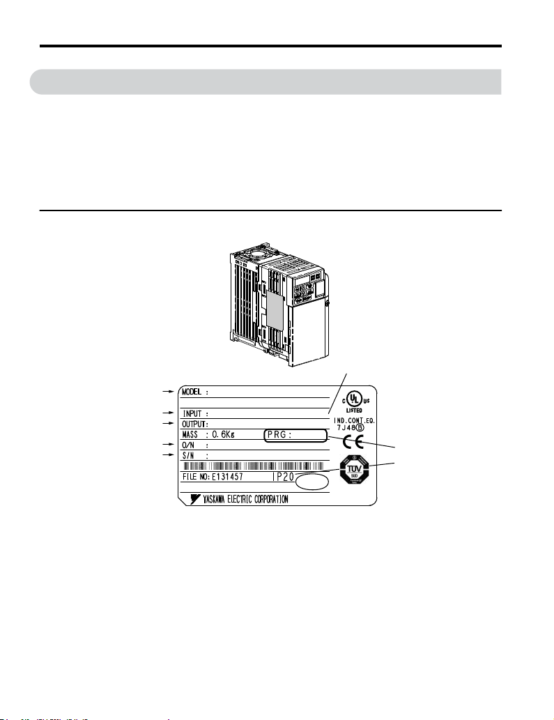
Nameplate
Normal Duty Amps/Heavy Duty Amps
AC drive model
Input specifications
Output specifications
Lot number
Serial number
CIMR-VU2A0001FAA REV:A
AC3PH 200-240V 50/60Hz
AC3PH 0-240V 0-400Hz 1.2A/0.8A
2.7/1.4A
1010
PASS
Assembled in USA
RoHSRoHS
Software version
Enclosure Type
Figure 1.1 Nameplate Information
26
YASKAWA ELECTRIC TOEP C710606 14E YASKAWA AC Drive – V1000 Quick Start Guide
Page 27
1.1 Model Number and Nameplate Check
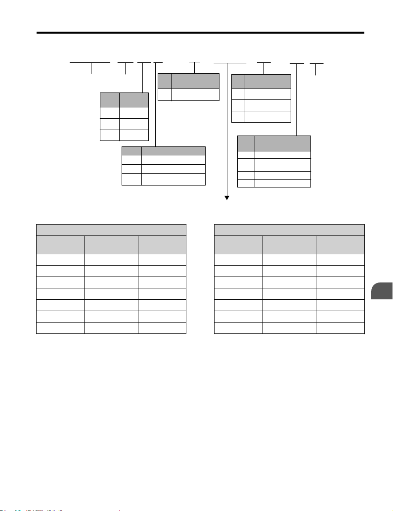
2
CIMR-
Drive
No.
U USA
A Japan
C Europe
Single-Phase 200 V
n
Normal Duty Heavy Duty
No.
0001 0.2 1.2 0001 0.1 0.8
0002 0.4 1.9 0002 0.2 1.6
0003 0.75 3.3 0003 0.4 3.0
0006 1.1 6.0 0006 0.75 5.0
0010 2.2 9.6 0010 1.5 8.0
0012 3.0 12.0 0012 2.2 11.0
— — — 0018 3.7 17.5
Note:
Max. Motor
Capacity kW
CIMR-VoBA0018 is available with a Heavy Duty rating only.
U
V
V1000
Series
Region
Code
No. Voltage Class
B
No.
1-phase, 200-240 Vac
3-phase, 200-240 Vac
2
3-phase, 380-480 Vac
4
Rated Output
Current A
Customized
Specifications
A Standard model
0001
A
Enclosure Type
No.
IP00/Open
A
B
IP20/Open
IP20/NEMA 1
F
No.
A
M
N
S
No.
B
Environmental
Specification <1>
Standard
Humidity- and
dust-resistant
Oil-resistant
Vibration-resistant
A
Max. Motor
Capacity kW
A
Design
Revision
Order
Rated Output
Current A
Receiving
1
YASKAWA ELECTRIC TOEP C710606 14E YASKAWA AC Drive – V1000 Quick Start Guide
27
Page 28

1.1 Model Number and Nameplate Check
Three-Phase 200 V
n
Normal Duty Heavy Duty
No.
0001 0.2 1.2 0001 0.1 0.8
0002 0.4 1.9 0002 0.2 1.6
0004 0.75 3.5 0004 0.4 3.0
0006 1.1 6.0 0006 0.75 5.0
0010 2.2 9.6 0010 1.5 8.0
0012 3.0 12.0 0012 2.2 11.0
0020 5.5 19.6 0020 5.5 19.6
0030 7.5 30.0 0030 5.5 25.0
0040 11 40.0 0040 7.5 33.0
0056 15 56.0 0056 11 47.0
0069 18.5 69.0 0069 15 69.0
Three-Phase 400 V
n
No.
0001 0.4 1.2 0001 0.2 1.2
0002 0.75 2.1 0002 0.4 1.8
0004 1.5 4.1 0004 0.75 3.4
0005 2.2 5.4 0005 1.5 4.8
0007 3.0 6.9 0007 2.2 5.5
0009 3.7 8.8 0009 3.0 7.2
0011 5.5 11.1 0011 3.7 9.2
0018 7.5 17.5 0018 5.5 14.8
0023 11 23.0 0023 7.5 18.0
0031 15 31.0 0031 11 24.0
0038 18.5 38.0 0038 15 31.0
Max Motor
Capacity kW
Normal Duty Heavy Duty
Max. Motor
Capacity kW
Rated Output
Current A
Rated Output
Current A
No.
No.
Max Motor
Capacity kW
Max. Motor
Capacity kW
Rated Output
Current A
Rated Output
Current A
<1> Drives with these specifications do not guarantee complete protection for the specified
environmental condition.
28
YASKAWA ELECTRIC TOEP C710606 14E YASKAWA AC Drive – V1000 Quick Start Guide
Page 29

1.2 Component Names
1.2 Component Names
This section illustrates the drive components as they are mentioned in this manual.
u
IP20/Open-Chassis
Single-Phase AC200 V CIMR-VoBA0001B ~ 0003B
n
Three-Phase AC200 V CIMR-Vo2A0001B ~ 0006B
A
L
K
J
H
I
E
G
A –
Fan cover
B – Mounting hole
C – Heatsink
D – Optional 24 V DC power
supply connector cover
E – Terminal board Refer to
Control Circuit Terminal
Block Functions on page
65
F – Terminal cover
Figure 1.2 Exploded View of IP20/Open-Chassis Type Components
<1> The drives CIMR-VoBA0001B ~ 0003B and CIMR-Vo2A0001B ~ 0004B do not have a
cooling fan or a cooling fan cover.
<1>
Three-Phase AC200 V CIMR-Vo2A0006B
F
G – Front cover screw
H – Front cover
I – Comm port
J – LED operator Refer to
Using the Digital LED
Operator on page 80
K – Case
L –
Cooling fan
B
C
D
<1>
Receiving
1
YASKAWA ELECTRIC TOEP C710606 14E YASKAWA AC Drive – V1000 Quick Start Guide
29
Page 30
1.2 Component Names
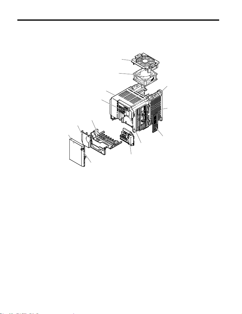
Single-Phase AC200 V CIMR-VoBA0006B ~ 0018B
n
Three-Phase AC200 V CIMR-Vo2A0010B ~ 0020B
Three-Phase AC400 V CIMR-Vo4A0001B ~ 0011B
A
M
L
B
K
C
J
I
H
D
E
F
G
A –
Fan cover
B – Mounting hole
C – Heatsink
D – Optional 24 V DC power
supply connector cover
E – Comm port
F – Terminal board Refer to
Control Circuit Terminal
Block Functions on page
65
G – Front cover screw
Figure 1.3 Exploded view of IP20/Open-Chassis Type Components
<1> The drives CIMR-VoBA0006B and CIMR-Vo4A0001B ~ 0004B do not have a cooling fan
or a cooling fan cover. The drive CIMR-VoBA0018B has two cooling fans.
<1>
Three-Phase AC200 V CIMR-Vo2A0012B
H – Front cover
I – Terminal cover
J – Bottom cover
K – LED operator Refer to
Using the Digital LED
Operator on page 80
L – Case
M –
Cooling fan
<1>
30
YASKAWA ELECTRIC TOEP C710606 14E YASKAWA AC Drive – V1000 Quick Start Guide
Page 31

u
IP00/Open-Chassis
Three-Phase AC200 V CIMR-VoBA0030A ~ 0069A
n
Three-Phase AC400 V CIMR-Vo2A0018A ~ 0038A
A
B
1.2 Component Names
M
C
L
D
J
I
K
E
H
F
G
A – Fan cover
B – Cooling Fan
C – Mounting hole
D – Heatsink
E – Optional 24 VDC power
supply connector cover
F – Terminal board Refer to
Control Circuit Terminal
Block Functions on page
65
G – Bottom cover
Figure 1.4 Exploded View of IP00/Open-Chassis Type Components
Three-Phase AC400 V CIMR-Vo4A0018A
H – Front cover screw
I – Front cover
J – Terminal cover
K – Comm port
L – LED operator Refer to
Using the Digital LED
Operator on page 80
M – Case
Receiving
1
YASKAWA ELECTRIC TOEP C710606 14E YASKAWA AC Drive – V1000 Quick Start Guide
31
Page 32

1.2 Component Names
u
IP20/NEMA Type 1 Enclosure
Single-Phase AC200 V CIMR-VoBA0001F ~ 0003F
n
Three-Phase AC200 V CIMR-Vo2A0001F ~ 0006F
A
O
N
M
L
K
J
E
I
H
B
C
D
F
G
A –
Fan cover
B – Mounting hole
C – Heatsink
D – Optional 24 V DC power
supply connector cover
E – Terminal board Refer to
Control Circuit Terminal
Block Functions on page
65
F – Bottom cover screws
G – Rubber bushing
H – Bottom front cover
Figure 1.5 Exploded View of IP20/NEMA Type 1 Components
<1> The drives CIMR-VoBA0001F ~ 0003F and CIMR-Vo2A0001F ~ 0004F do not have a
cooling fan or a cooling fan cover.
32
<1>
Three-Phase AC200 V CIMR-Vo2A0006F
YASKAWA ELECTRIC TOEP C710606 14E YASKAWA AC Drive – V1000 Quick Start Guide
I – Front cover screws
J – Front cover
K – Comm port
L – LED operator Refer to
Using the Digital LED
Operator on page 80
M – Case
N – Top cover
O –
Cooling fan
<1>
Page 33

Single-Phase AC200 V CIMR-VoBA0006F ~ 0018F
n
Three-Phase AC200 V CIMR-Vo2A0010F~ 0020F
Three-Phase AC400 V CIMR-Vo4A0001F ~ 0011F
A
P
1.2 Component Names
O
N
B
M
C
D
J
L
K
E
F
I
G
H
A –
Fan cover
B – Mounting hole
C – Heatsink
D – Optional 24 V DC power
supply connector cover
E – Terminal board Refer to
Control Circuit Terminal
Block Functions on page
65
F – Cover screws
G – Rubber bushing
H – Bottom cover
Figure 1.6 Exploded view of IP20/NEMA Type 1 Components
<1> The drives CIMR-VoBA0006B and CIMR-Vo4A0001B ~ 0004B do not have a cooling fan
or a cooling fan cover. The drive CIMR-VoBA0018B has two cooling fans.
<1>
Three-Phase AC200 V CIMR-Vo2A0012F
I – Front cover screws
J – Front cover
K – Terminal cover
L – Comm port
M – LED operator Refer to
Using the Digital LED
Operator on page 80
N – Case
O – Top cover
P –
Cooling fan
<1>
Receiving
1
YASKAWA ELECTRIC TOEP C710606 14E YASKAWA AC Drive – V1000 Quick Start Guide
33
Page 34

1.2 Component Names
Three-Phase AC200 V CIMR-Vo2A0030F ~ 0069F
n
Three-Phase AC400 V CIMR-Vo4A00018F ~ 0038F
P
O
N
M
L
K
J
F
A
B
C
D
E
I
A – Fan cover
B – Cooling fan
C – Mounting Hole
D – Case and Heatsink
E – Optional 24 V DC power
supply connection cover
F – Cover screws
G – Rubber bushing
H – Bottom cover
Figure 1.7 Exploded View of IP20/NEMA Type 1 Components
34
Three-Phase AC400 V CIMR-Vo4A0018F
YASKAWA ELECTRIC TOEP C710606 14E YASKAWA AC Drive – V1000 Quick Start Guide
I – Front cover screws
J – Terminal cover
K – Terminal board Refer to
L – Front cover
M – Comm port
N – LED operator Refer to
O – Case
P – Top cover
G
H
Control Circuit Terminal
Block Functions on page
65
Using the Digital LED
Operator on page 80
Page 35

u
Front Views
1.2 Component Names
CIMR-V 2A0006B CIMR-V 2A0012B
I
A
I
A
B
H
H
B
C
C
D
G
G
E
D
E
F
F
A – Terminal board
connector
B – DIP switch S1 Refer to
DIP Switch S1 Analog
Input Signal Selection on
page 75
C – DIP switch S3 Refer to
Sinking/Sourcing Mode
Switch on page 72
D – Control circuit terminal
Refer to Control Circuit
Wiring on page 65
E – Main circuit terminal
Refer to Wiring the Main
Circuit Terminal on page
64
Figure 1.8 Front Views of Drives
F – Ground terminal
G – Terminal cover
H – Option card connector
I – DIP switch S2
Receiving
1
YASKAWA ELECTRIC TOEP C710606 14E YASKAWA AC Drive – V1000 Quick Start Guide
35
Page 36

1.2 Component Names
This Page Intentionally Blank
36
YASKAWA ELECTRIC TOEP C710606 14E YASKAWA AC Drive – V1000 Quick Start Guide
Page 37

2
Mechanical
Installation
This chapter explains how to properly mount and install the
drive.
2.1 MECHANICAL INSTALLATION..........................38
YASKAWA ELECTRIC TOEP C710606 14E YASKAWA AC Drive – V1000 Quick Start Guide
37
Page 38

2.1 Mechanical Installation
2.1 Mechanical Installation
This section outlines specifications, procedures, and environment for proper mechanical
installation of the drive.
u
Installation Environment
To help prolong the optimum performance life of the drive, install the drive in the proper
environment. The table below provides a description of the appropriate environment for the
drive.
Table 2.1 Installation Environment
Environment Conditions
Installation Area Indoors
-10 °C to +40 °C (IP20/NEMA 1)
Ambient
Temperature
Humidity 95% RH or less and free of condensation
Storage Temperature -20 °C to +60 °C
Surrounding Area
Altitude 1000 m or lower
Vibration
Orientation Install the drive vertically to maintain maximum cooling effects.
NOTICE: Prevent foreign matter such as metal shavings or wire clippings from falling into the drive during
installation and project construction. Failure to comply could result in damage to the drive. Place a temporary
cover over the top of the drive during installation. Remove the temporary cover before startup, as the cover
will reduce ventilation and cause the drive to overheat.
NOTICE: Avoid placing drive peripheral devices, transformers, or other electronics near the drive. Failure to
comply could result in erroneous operation. If such devices must be used in close proximity to the drive, take
proper steps to shield the drive from noise.
-10 °C to +50 °C (IP20/Open-Chassis)
Drive reliability improves in environments without wide temperature fluctuations.
When using an enclosure panel, install a cooling fan or air conditioner in the area to ensure
that the air temperature inside the enclosure does not exceed the specified levels.
Do not allow ice to develop on the drive.
Install the drive in an area free from:
• oil mist and dust
• metal shavings, oil, water or other foreign materials
• radioactive materials
• combustible materials (e.g., wood)
• harmful gases and liquids
• excessive vibration
• chlorides
• direct sunlight
10 to 20 Hz at 9.8 m/s
20 to 55 Hz at 5.9 m/s
2
2
38
YASKAWA ELECTRIC TOEP C710606 14E YASKAWA AC Drive – V1000 Quick Start Guide
Page 39

2.1 Mechanical Installation
u
Installation Orientation and Spacing
Install the drive upright as illustrated in Figure 2.1 to maintain proper cooling.
A
A – Correct B – Incorrect
Figure 2.1 Correct Installation Orientation
Single Drive Installation
n
Figure 2.2 explains the required installation spacing to maintain sufficient space for airflow
and wiring. Install the heatsink against a closed surface to avoid diverting cooling air around
the heatsink.
B
B
Mechanical Installation
2
YASKAWA ELECTRIC TOEP C710606 14E YASKAWA AC Drive – V1000 Quick Start Guide
39
Page 40

2.1 Mechanical Installation
Side Clearance
A A
A – 30 mm minimum
B – Airflow direction
Figure 2.2 Correct Installation Spacing
Note: IP20/NEMA Type 1 and IP20/Open-Chassis models require the same amount of space above and below
the drive for installation.
Multiple Drive Installation
n
Top/Bottom Clearance
C
B
C
C – 100 mm minimum
When installing multiple drives into the same enclosure panel, mount the drives according to
Figure 2.2. When mounting drives with a minimum side-by-side clearance of 2 mm according
to Figure 2.3, derating must be considered and parameter L8-35 must be set. Refer to
Parameter List on page 157.
40
YASKAWA ELECTRIC TOEP C710606 14E YASKAWA AC Drive – V1000 Quick Start Guide
Page 41
2.1 Mechanical Installation
B
A
2 mm
B
C
C
A – Line up the tops of the
drives.
B – 30 mm minimum
Figure 2.3 Space Between Drives (Side-by-Side Mounting)
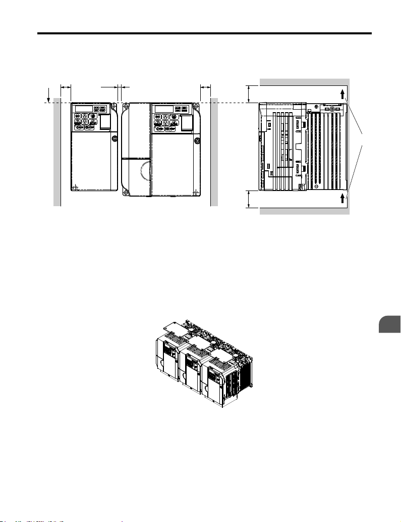
Note: When installing drives of different heights in the same enclosure panel, the tops of the drives should line
up. Leave space between the top and bottom of stacked drives for cooling fan replacement if required. Using
this method, it is possible to replace the cooling fans later.
NOTICE: When drives with IP20/NEMA Type 1 enclosures are mounted side by side, the top covers of all
drives must be removed as shown in Figure 2.4.
C – 100 mm minimum
D – Airflow direction
D
Mechanical Installation
2
Figure 2.4 IP20/NEMA 1 Side-by-Side Mounting in Enclosure
YASKAWA ELECTRIC TOEP C710606 14E YASKAWA AC Drive – V1000 Quick Start Guide
41
Page 42

2.1 Mechanical Installation
u
Exterior and Mounting Dimensions
IP20/Open-Chassis Drives
n
Table 2.2 IP20/Open-Chassis (without an EMC filter)
W1
2-M4
H1H2
H
t1
Voltage Class
Single-Phase
200 V Class
Three-Phase
200 V Class
42
W
Drive Model
CIMR-Vo
BA0001B 2.68 5.04 2.99 2.20 4.65 0.20 0.26 0.12 1.3
BA0002B 2.68 5.04 2.99 2.20 4.65 0.20 0.26 0.12 1.3
BA0003B 2.68 5.04 4.65 2.20 4.65 0.20 1.52 0.20 2.2
2A0001B 2.68 5.04 2.99 2.20 4.65 0.20 2.26 0.12 1.3
2A0002B 2.68 5.04 2.99 2.20 4.65 0.20 2.26 0.12 1.3
2A0004B 2.68 5.04 4.25 2.20 4.65 0.20 1.52 0.20 2.0
2A0006B 2.68 5.04 5.04 2.20 4.65 0.20 2.30 0.20 2.4
W H D W1 H1 H2 D1 t1 Wt. (lb.)
YASKAWA ELECTRIC TOEP C710606 14E YASKAWA AC Drive – V1000 Quick Start Guide
D
Dimensions (in)
D1
Page 43

Voltage Class
Single-Phase
200 V Class
Three-Phase
200 V Class
Three-Phase
400 V Class
2.1 Mechanical Installation
Table 2.3 IP20/Open-Chassis (without an EMC filter)
W1
W
Drive Model
CIMR-Vo
BA0006B 4.25 5.04 5.41 3.78 4.65 0.20 2.28 0.20 3.7
BA0010B 4.25 5.04 6.06 3.78 4.65 0.20 2.28 0.20 4.0
BA0012B 5.51 5.04 6.42 5.04 4.65 0.20 2.56 0.20 5.3
BA0018B 6.69 5.04 7.09 6.22 4.65 0.20 2.56 0.20 6.6
2A0010B 4.25 5.04 5.08 3.78 4.65 0.20 2.28 0.20 3.7
2A0012B 4.25 5.04 5.41 3.78 4.65 0.20 2.28 0.20 3.7
2A0020B 5.51 5.04 5.63 5.04 4.65 0.20 2.56 0.20 5.3
4A0001B 4.25 5.04 3.19 3.78 4.65 0.20 0.39 0.20 2.2
4A0002B 4.25 5.04 3.90 3.78 4.65 0.20 1.10 0.20 2.6
4A0004B 4.25 5.04 5.41 3.78 4.65 0.20 2.28 0.20 3.7
4A0005B 4.25 5.04 6.06 3.78 4.65 0.20 2.28 0.20 3.7
4A0007B 4.25 5.04 6.06 3.78 4.65 0.20 2.28 0.20 3.7
4A0009B 4.25 5.04 6.06 3.78 4.65 0.20 2.28 0.20 3.7
4A0011B 5.51 5.04 5.63 5.04 4.65 0.20 2.56 0.20 5.3
4-M4
H
t1
H2 H1
W H D W1 H1 H2 D1 t1 Wt. (lb.)
D
Dimensions (in)
D1
Mechanical Installation
2
YASKAWA ELECTRIC TOEP C710606 14E YASKAWA AC Drive – V1000 Quick Start Guide
43
Page 44
2.1 Mechanical Installation
IP00/Open-Chassis Drives
n
Table 2.4 IP00/Open-Chassis (without an EMC filter)
W1
4-d
H
H2
H1
Voltage Class
Three-Phase
200 V Class
Three-Phase
400 V Class
44
t1
D1
D
Drive
Model
CIMR-Vo
W
H4
Dimensions (in)
W H D W1 H1 H2 H4 D1 d t1 Wt. (lb)
2A0030A 5.5 9.7 5.5 4.8 9.2 9.8 0.5 2.2 M5 0.2 7.9
2A0040A 5.5 9.7 5.5 4.8 9.2 9.8 0.5 2.2 M5 0.2 7.9
2A0056A 7.1 11.2 6.4 6.3 10.6 11.2 0.6 3.0 M5 0.2 11.7
2A0069A 8.7 13.2 7.4 7.6 12.6 13.2 0.6 3.1 M6 0.2 19.2
4A0018A 5.5 9.7 5.5 4.8 9.2 9.8 0.5 2.2 M5 0.2 7.9
4A0023A 5.5 9.7 5.5 4.8 9.2 9.8 0.5 2.2 M5 0.2 7.9
4A0031A 7.1 11.2 5.6 6.3 10.6 11.2 0.6 2.2 M5 0.2 11.0
4A0038A 7.1 11.2 6.4 6.3 10.6 11.2 0.6 3.0 M5 0.2 11.7
YASKAWA ELECTRIC TOEP C710606 14E YASKAWA AC Drive – V1000 Quick Start Guide
Page 45
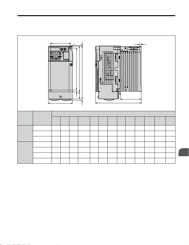
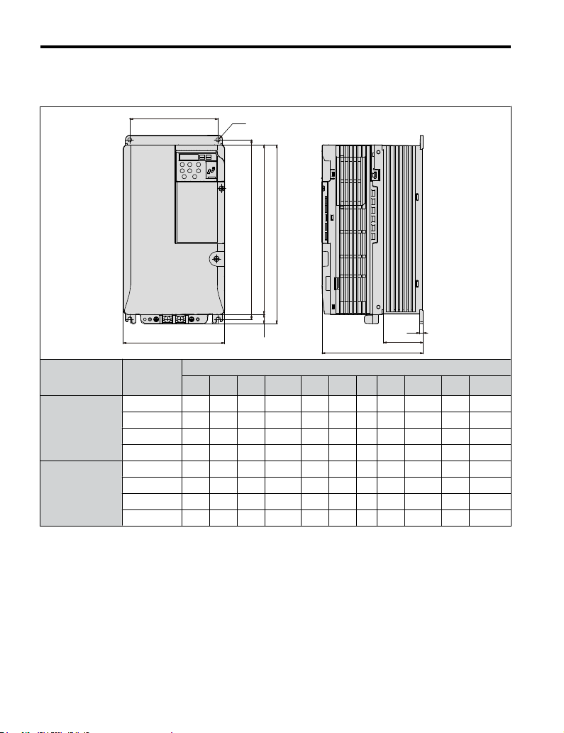
IP20/NEMA Type 1 Drives
n
Table 2.5 IP20/NEMA Type 1 (without an EMC filter)
W1
W
2-M4
2.1 Mechanical Installation
H6
HH3
H2
H1
H4
H5
D
t1
D1
Voltage
Class
Single-
Phase
200 V
Class
Three-
Phase
200 V
Class
Drive
Model
CIMR-Vo
BA0001F 2.68 5.89 2.99 2.20 5.03 4.65 0.16 0.79 0.20 0.06 0.26 0.12 1.8
BA0002F 2.68 5.89 2.99 2.20 5.03 4.65 0.16 0.79 0.20 0.06 0.26 0.12 1.8
BA0003F 2.68 5.89 4.65 2.20 5.03 4.65 0.16 0.79 0.20 0.06 1.54 0.20 2.6
2A0001F 2.68 5.89 2.99 2.20 5.03 4.65 0.16 0.79 0.20 0.06 0.26 0.12 1.8
2A0002F 2.68 5.89 2.99 2.20 5.03 4.65 0.16 0.79 0.20 0.06 0.26 0.12 1.8
2A0004F 2.68 5.89 4.25 2.20 5.03 4.65 0.16 0.79 0.20 0.06 1.54 0.20 2.4
2A0006F 2.68 5.89 5.04 2.20 5.03 4.65 0.16 0.79 0.20 0.06 2.32 0.20 2.9
W H D W1 H1 H2 H3 H4 H5 H6 D1 t1
Dimensions (in)
YASKAWA ELECTRIC TOEP C710606 14E YASKAWA AC Drive – V1000 Quick Start Guide
Wt.
(lb.)
Mechanical Installation
2
45
Page 46

2.1 Mechanical Installation
Table 2.6 IP20/NEMA Type 1 (without an EMC filter)
W1
W
Voltage
Class
Single-
Phase
200 V
Class
Three-
Phase
200 V
Class
Three-
Phase
400 V
Class
Drive
Model
CIMR-Vo
W H D W1 H1 H2 H3 H4 H5 H6 D1 t1
BA0006F 4.25 5.89 5.41 3.78 5.03 4.65 0.16 0.79 0.20 0.06 2.28 0.20 4.2
BA0010F 4.25 5.89 6.06 3.78 5.03 4.65 0.16 0.79 0.20 0.06 2.28 0.20 4.4
BA0012F 5.51 6.02 6.42 5.04 5.03 4.65 0.19 0.79 0.20 0.20 2.56 0.20 5.7
BA0018F 6.69 6.73 7.08 6.22 5.23 4.64 0.19 1.50 0.20 0.20 2.56 0.20 7.3
2A0010F 4.25 5.89 5.08 3.78 5.03 4.65 0.16 0.79 0.20 0.06 2.28 0.20 4.2
2A0012F 4.25 5.89 5.41 3.78 5.03 4.65 0.16 0.79 0.20 0.06 2.28 0.20 4.2
2A0020F 5.51 6.02 5.63 5.04 5.03 4.65 0.19 0.79 0.20 0.20 2.56 0.20 5.7
4A0001F 4.25 5.89 3.19 3.78 5.03 4.65 0.16 0.79 0.20 0.06 0.39 0.20 2.6
4A0002F 4.25 5.89 3.90 3.78 5.03 4.65 0.16 0.79 0.20 0.06 1.10 0.20 3.1
4A0004F 4.25 5.89 5.41 3.78 5.03 4.65 0.16 0.79 0.20 0.06 2.28 0.20 4.2
4A0005F 4.25 5.89 6.06 3.78 5.03 4.65 0.16 0.79 0.20 0.06 2.28 0.20 4.2
4A0007F 4.25 5.89 6.06 3.78 5.03 4.65 0.16 0.79 0.20 0.06 2.28 0.20 4.2
4A0009F 4.25 5.89 6.06 3.78 5.03 4.65 0.16 0.79 0.20 0.06 2.28 0.20 4.2
4A0011F 5.51 6.02 5.63 5.04 5.03 4.65 0.19 0.79 0.20 0.20 2.56 0.20 5.7
4-M4
H6
HH3
H1
H5 H2
H4
D
t1
D1
Dimensions (in)
Wt.
(lb.)
46
YASKAWA ELECTRIC TOEP C710606 14E YASKAWA AC Drive – V1000 Quick Start Guide
Page 47

Voltage
Class
Three-
Phase
200 V
Class
Three-
Phase
400 V
Class
2.1 Mechanical Installation
Table 2.7 IP20/NEMA Type 1 (without an EMC filter)
W1
W
Drive
Model
CIMR-Vo
2A0030F 5.51 10.00 5.51 4.80 9.21 9.76 0.24 0.51 0.51 0.06 2.17 0.20 M5 8.4
2A0040F 5.51 10.00 5.51 4.80 9.21 9.76 0.24 0.51 0.51 0.06 2.17 0.20 M5 8.4
2A0056F 7.09 11.42 6.42 6.30 10.63 11.18 0.24 0.59 0.51 0.06 2.95 0.20 M5 12.1
2A0069F 8.66 13.78 7.36 7.56 12.60 13.23 0.28 0.59 0.87 0.06 3.07 0.20 M5 20.3
4A0018F 5.51 10.00 5.51 4.80 9.21 9.76 0.24 0.51 0.51 0.06 2.17 0.20 M5 8.4
4A0023F 5.51 10.00 5.51 4.80 9.21 9.76 0.24 0.51 0.51 0.06 2.17 0.20 M5 8.4
4A0031F 7.09 11.42 5.63 6.30 10.63 11.18 0.24 0.59 0.51 0.06 2.17 0.20 M5 11.5
4A0038F 7.09 11.42 6.42 6.30 10.63 11.18 0.24 0.51 0.51 0.06 2.95 0.20 M5 12.1
W H D W1 H1 H2 H3 H4 H5 H6 D1 t1 d
4-d
H6
H
H2
H1
t1
H4
H5
H3
Dimensions (in)
D1
D
Wt.
(lb.)
Mechanical Installation
2
YASKAWA ELECTRIC TOEP C710606 14E YASKAWA AC Drive – V1000 Quick Start Guide
47
Page 48

2.1 Mechanical Installation
This Page Intentionally Blank
48
YASKAWA ELECTRIC TOEP C710606 14E YASKAWA AC Drive – V1000 Quick Start Guide
Page 49

3
Electrical
Installation
This chapter explains proper procedures for wiring the control
circuit terminals, motor and power supply.
3.1 STANDARD CONNECTION DIAGRAM...............50
3.2 TERMINAL BLOCK CONFIGURATION..............53
3.3 PROTECTIVE COVERS.....................................54
3.4 MAIN CIRCUIT WIRING.....................................59
3.5 CONTROL CIRCUIT WIRING.............................65
3.6 I/O CONNECTIONS...........................................72
3.7 MAIN FREQUENCY REFERENCE......................75
3.8 WIRING CHECKLIST.........................................77
YASKAWA ELECTRIC TOEP C710606 14E YASKAWA AC Drive – V1000 Quick Start Guide
49
Page 50

3.1 Standard Connection Diagram
3.1 Standard Connection Diagram
Connect the drive and peripheral devices as shown in Figure 3.1. It is possible to run the drive
via the digital operator without connecting digital I/O wiring. This section does not discuss
drive operation; Refer to Start-Up Programming & Operation on page 79 for instructions
on operating the drive.
NOTICE: Inadequate branch short circuit protection could result in damage to the drive. Install adequate
branch circuit short circuit protection per applicable codes. The drive is suitable for circuits capable of
delivering not more than 30,000 RMS symmetrical amperes, 240 Vac maximum (200 V Class) and 440 Vac
maximum (400 V Class).
NOTICE: When the input voltage is 480 V or higher or the wiring distance is greater than 100 meters, pay
special attention to the motor insulation voltage or use a drive duty motor. Failure to comply could lead to
motor insulation breakdown.
NOTICE: Do not connect AC control circuit ground to drive enclosure. Improper drive grounding can cause
control circuit malfunction.
NOTICE: The minimum load for the multi-function relay output MA-MB-MC is 10 mA. If a circuit requires less
than 10 mA (reference value), connect it to a photocoupler output (P1, P2, PC). Improper application of
peripheral devices could result in damage to the photocoupler output of the drive.
50
YASKAWA ELECTRIC TOEP C710606 14E YASKAWA AC Drive – V1000 Quick Start Guide
Page 51

3.1 Standard Connection Diagram
For single phase
200 V power supply
Wiring sequence should shut off
power to the drive when a fault
output is triggered.
use R/L1 and S/L2.
<8>
R/L1
Three phase
S/L2
power supply
200 to 240 V
T/L3
THRX
1
MC
OFF
2
MC
TRX
Fault relay contact
Main speed
frequency
reference.
Multi-function
programmable
MB
TRX
Braking resistor unit
Thermal relay trip contact
Digital inputs
(default setting)
Terminals +1, +2, , B1, and B2
are for connecting options.
Never connect power supply
lines to these terminals.
MC
1 MCCB
ON
MC
Forward run/stop
SA
Reverse run/stop
THRX
External fault
SA
Fault reset
Multi-step
TRX
speed 1
main/aux switch
SA
Multi-step
speed 2
Jog reference
2 k
Safe Disable
Input
2 MCCB
<4>
Safety switch
Jumper
DC reactor
(option)
<3>
r1
s1
t1
R/L1
S/L2
T/L3
S1
S2
S3
S4
S5
S6
S7
<5>
DIP
switch S3
SC
Shield ground
terminal
Pulse train input
RP
(max. 32 kHz)
Setting power supply
+V
+10.5 max. 20 mA
A1
0 to +10 V (20 k )
A2
0 to +10 V (20 k )
(0)4 to 20 mA (250 )
AC
HC
<7>
H1
shielded line
main circuit terminal
<1>
Jumper
V1000
Main circuit
Control circuit
DIP
switch
S2
<2>
Thermal relay
(option)
-
B1+1+2 B2
Option card
connector
DIP switch S1
+
24 V 8mA
24 V
Sink
Source
0 V
Cable shield ground
twisted-pair shielded line
control terminal
Braking resistor
(option)
U/T1
V/T2
W/T3
V I
Termination
resistor
120 , 1/2 W
FU
r1
FV
s1
FW
t1
U
V
W
Ground
10 or less (400 V class)
100 or less (200 V class)
Digital output
250 Vac, 10 mA to 1 A
30 Vdc, 10 mA to 1 A
(default setting)
Fault
MA
Pulse train output
0 to 32 kHz
Comm.
connector
+
R
-
R
+
S
-
S
IG
Digital output
5 ~ 48 Vdc
2 to 50 mA
(default setting)
During Run
(photocoupler 1)
Frequency agree
(photocoupler 2)
Photocoupler
output common
+
AM
-
MB
MC
P1
P2
PC
MP
AM
AC
Motor
Cooling fan
M
M
<6>
Analog monitor
output
0 to +10 Vdc
(2 mA)
Monitor
output
MEMOBUS/
Modbus comm.
RS-485/422
Electrical Installation
3
Figure 3.1 Drive Standard Connection Diagram
<1> Remove the jumper when installing an optional DC reactor.
YASKAWA ELECTRIC TOEP C710606 14E YASKAWA AC Drive – V1000 Quick Start Guide
51
Page 52

3.1 Standard Connection Diagram
<2> The MC on the input side of the main circuit should open when the thermal relay is
triggered.
<3> Self-cooled motors do not require separate cooling fan motor wiring.
<4> Connected using sequence input signal (S1 to S7) from NPN transistor; Default: sink
mode (0 V com).
<5> Use only a +24 V internal power supply in sinking mode; the source mode requires
an external power supply Refer to I/O Connections on page 72.
<6> Monitor outputs work with devices such as analog frequency meters, ammeters,
voltmeters and wattmeters; they are not intended for use as a feedback-type of signal.
<7> Disconnect the wire jumper between HC and H1 when utilizing the safety input. Refer
to Wiring Procedure on page 70 for details on removing the jumper. The wire length
for the Safe Disable input should not exceed 30 m.
<8> Note that if the drive is set to trigger a fault output whenever the fault restart function
is activated (L5-02 = 1), then a sequence to interrupt power when a fault occurs will
result in shutting off the power to the drive as the drive attempts to restart itself. The
default setting for L5-02 is 0 (fault output active during restart attempt).
WARNING! Sudden Movement Hazard. Do not close the wiring for the control circuit unless the multifunction
input terminal parameter is properly set (S5 for 3-Wire; H1-05 = “0”). Improper sequencing of run/stop circuitry
could result in death or serious injury from moving equipment.
WARNING! Sudden Movement Hazard. Ensure start/stop and safety circuits are wired properly and in the
correct state before energizing the drive. Failure to comply could result in death or serious injury from moving
equipment. When programmed for 3-Wire control, a momentary closure on terminal S1 may cause the drive
to start.
WARNING! When 3-Wire sequence is used, set the drive to 3-Wire sequence before wiring the control
terminals and ensure parameter b1-17 is set to 0 (drive does not accept a run command at power up (default).
If the drive is wired for 3-Wire sequence but set up for 2-Wire sequence (default) and if parameter b1-17 is
set to 1 (drive accepts a Run command at power up), the motor will rotate in reverse direction at power up of
the drive and may cause injury.
WARNING! When the application preset function is executed (or A1-06 is set to any value other than 0) the
drive I/O terminal functions change. This may cause unexpected operation and potential damage to
equipment or injury.
Figure 3.2 illustrates an example of a 3-Wire sequence.
Stop relay (N.C.)
Run relay (N.O.)
S1
Run command (run on momentary close)
S2
Stop command (stop on momentary open)
S5
Foward/reverse command
(multi-function input: H1-05 = 0)
SC
Sequence input common
Drive
Figure 3.2 3-Wire Sequence
52
YASKAWA ELECTRIC TOEP C710606 14E YASKAWA AC Drive – V1000 Quick Start Guide
Page 53

3.2 Terminal Block Configuration
3.2 Terminal Block Configuration
The figures in this section provide illustrations of the main circuit terminal block
configurations of the different drive sizes.
Models: CIMR-V
BA0001, 0002, 0003
CIMR-V2A0001, 0002, 0004, 0006
Models: CIMR-V
CIMR-V4A0018, 0023
Model: CIMR-V
Figure 3.3 Main Circuit Terminal Block Configurations
2A0030, 0040
BA0018
Models: CIMR-V
BA0006, 0010, 0012
CIMR-V2A0010, 0012, 0020
CIMR-V4A0001, 0002, 0004, 0005
0007, 0009, 0011
Model: CIMR-V
Models: CIMR-V
CIMR-V4A0031, 0038
2A0056
2A0069
Electrical Installation
3
YASKAWA ELECTRIC TOEP C710606 14E YASKAWA AC Drive – V1000 Quick Start Guide
53
Page 54

3.3 Protective Covers
3.3 Protective Covers
Follow the procedure below to remove the protective covers before wiring the drive and to
reattach the covers after wiring is complete.
u
IP20/Open-Chassis Front and Bottom Cover Removal and Installation
Removing the Protective Covers
n
Loosen the screw that locks the front cover in place to remove.
1.
Figure 3.4 Remove the Front Cover on an IP20/Open-Chassis Drive
Apply pressure to the tabs on each side of the terminal cover. Pull the terminal cover
2.
away from the drive while pushing in on the tabs to pull the cover free.
Figure 3.5 Remove the Terminal Cover on an IP20/Open-Chassis Drive
Reattaching the Protective Covers
n
Properly connect all wiring and route power wiring away from control signal wiring. Reattach
all protective covers when wiring is complete. Apply only a small amount of pressure to lock
the cover back into place.
54
YASKAWA ELECTRIC TOEP C710606 14E YASKAWA AC Drive – V1000 Quick Start Guide
Page 55
3.3 Protective Covers
Figure 3.6 Reattach the Protective Covers on an IP20/Open-Chassis Drive
u
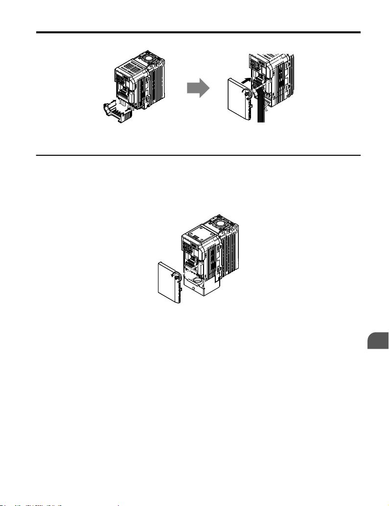
IP20/NEMA Type 1 Front and Bottom Cover Removal and Installation
Removing the Protective Covers on an IP20/NEMA Type 1 Design
n
Loosen the screw on the front cover to remove the front cover.
1.
Figure 3.7 Remove the Front Cover on an IP20/NEMA Type 1 Drive
Loosen the screw on the terminal cover to remove the terminal cover and expose the
2.
conduit bracket.
YASKAWA ELECTRIC TOEP C710606 14E YASKAWA AC Drive – V1000 Quick Start Guide
Electrical Installation
3
55
Page 56

3.3 Protective Covers
A
A – Conduit bracket B – Terminal cover
Figure 3.8 Remove the Terminal Cover on an IP20/NEMA Type 1 Drive
Loosen two screws attaching the conduit bracket to remove.
3.
A
A – Conduit bracket
Figure 3.9 Remove the Conduit Bracket on an IP20/NEMA Type 1 Drive
Reattaching the Protective Covers
n
Pass power wiring and control signal wiring through the exit holes on the bottom of the conduit
bracket of the drive. Place power wiring and control signal wiring in separate conduits.
Properly connect all wiring after installing the drive and connecting other devices. Reattach
all protective covers when wiring is complete.
B
56
YASKAWA ELECTRIC TOEP C710606 14E YASKAWA AC Drive – V1000 Quick Start Guide
Page 57

3.3 Protective Covers
A
A – Pass power wiring and control signal wiring through different
exit holes at the bottom of the drive.
Figure 3.10 Reattach the Protective Covers and Conduit Bracket on an IP20/NEMA
u
IP20/NEMA Type 1 Top Cover Removal and Installation
Type 1 Drive
To improve the ambient temperature rating of a NEMA Type 1 drive from 40 °C to 50 °C or
to mount NEMA Type 1 drives side-by-side, the top cover can be removed. Remove the top
cover and set L8-35 to “2”.
Note: Removing the top cover of a NEMA Type 1 drive converts the drive to an IP20/Open-Chassis rating, and
the drive will no longer have a NEMA Type 1 rating.
Removing the Top Cover
n
Insert the blade of a straight-edge screwdriver into the opening of the top cover. Gently lift
up on the front cover as indicated by the arrow in Figure 3.11 to remove it from the drive.
Figure 3.11 Removing the Top Cover
Reattaching the Top Cover
n
Align the connection tabs on the underside of the top cover with the connection tabs on the
drive. Pinch in on the top cover to click the cover into place on the drive.
YASKAWA ELECTRIC TOEP C710606 14E YASKAWA AC Drive – V1000 Quick Start Guide
Electrical Installation
3
57
Page 58

3.3 Protective Covers
Connection tabs
Figure 3.12 Reattaching the Top Cover
58
YASKAWA ELECTRIC TOEP C710606 14E YASKAWA AC Drive – V1000 Quick Start Guide
Page 59

3.4 Main Circuit Wiring
3.4 Main Circuit Wiring
This section describes the functions, specifications, and procedures required to safely and
properly wire the main circuit of the drive.
NOTICE: Do not solder the ends of wire connections to the drive. Soldered wiring connections can loosen
over time. Improper wiring practices could result in drive malfunction due to loose terminal connections.
u
Main Circuit Terminal Functions
Table 3.1 Main Circuit Terminal Functions
Terminal Type Function Reference
R/L1
T/L3
U/T1
W/T3
B1
B2
+1
+2
+1
–
(2 terminals)
Main circuit power
supply input
Drive output Connects to the motor. 63V/T2
Braking resistor
DC reactor
connection
DC power supply
input
Ground
Connects line power to the drive.
Drives with single-phase 200 V input power use terminals R/
L1 and S/L2 only (T/L3 must not be used).
Available for connecting a braking resistor or the braking
resistor unit option.
These terminals are shorted at shipment. Remove the shorting
bar between +1 and +2 when connecting a DC reactor to this
terminal.
For connecting a DC power supply. –
Grounding Terminal
For 200 V class: 100 Ω or less
For 400 V class: 10 Ω or less
–S/L2
–
–
63
Electrical Installation
u
Wire Gauges and Tightening Torque
Select the appropriate wires and crimp terminals from Table 3.2 through Table 3.4.
Note: 1. Wire gauge recommendations based on drive continuous current ratings using 75 °C 600 Vac vinyl-
sheathed wire assuming ambient temperature within 30 °C and wiring distance less than 100 m.
2. Terminals +1, +2, –, B1 and B2 are for connecting optional devices such as a DC reactor or braking
resistor. Do not connect other non-specified devices to these terminals.
• Consider the amount of voltage drop when selecting wire gauges. Increase the wire gauge
when the voltage drop is greater than 2% of motor rated voltage. Ensure the wire gauge is
suitable for the terminal block. Use the following formula to calculate the amount of voltage
drop:
•
Line drop voltage (V) =
YASKAWA ELECTRIC TOEP C710606 14E YASKAWA AC Drive – V1000 Quick Start Guide
3 x wire resistance (Ω/km) x wire length (m) x current (A) x 10
3
-3
59
Page 60

3.4 Main Circuit Wiring
• Refer to instruction manual TOBPC72060000 for braking unit or braking resistor unit wire
gauges.
• Refer to UL Standards Compliance on page 200 for information on UL compliance.
Single-Phase 200 V Class
n
Table 3.2 Wire Gauge and Torque Specifications
Model
CIMRVoBA
0001
R/L1, S/L2, U/T1, V/T2, W/T3,
0002
–, +1, +2, B1, B2,
0003
R/L1, S/L2, U/T1, V/T2, W/T3,
0006
–, +1, +2, B1, B2,
R/L1, S/L2, U/T1, V/T2, W/T3,
0010
–, +1, +2, B1, B2 M4
R/L1, S/L2, U/T1, V/T2, W/T3,
0012
–, +1, +2, B1, B2,
R/L1, S/L2, U/T1, V/T2, W/T3,
0018
–, +1, +2, B1, B2,
Three-Phase 200 V Class
n
Model
CIMRVo2A
0001
R/L1, S/L2, T/L3, U/T1, V/T2, W/
0002
0004
T3, –, +1, +2, B1, B2,
0006
R/L1, S/L2, T/L3, U/T1, V/T2, W/
T3, –, +1, +2, B1, B2
0010
R/L1, S/L2, T/L3, U/T1, V/T2, W/
0012
T3, –, +1, +2, B1, B2,
R/L1, S/L2, T/L3, U/T1, V/T2, W/
0020
T3, –, +1, +2, B1, B2,
Terminal
Table 3.3 Wire Gauge and Torque Specifications
Terminal
Screw
Size
M3.5
M4
M4
M4
M5
Screw
Size
M3.5
M4
M4
M4
M4
Tightening
Torque
N•m (lb.in.)
0.8 to 1.0
(7.1 to 8.9)
1.2 to 1.5
(10.6 to 13.3)
1.2 to 1.5
(10.6 to 13.3)
1.2 to 1.5
(10.6 to 13.3)
1.2 to 1.5
(10.6 to 13.3)
2 to 2.5
(17.7 to 22.1)
Tightening
Torque
N•m (lb.in.)
0.8 to 1.0
(7.1 to 8.9)
1.2 to 1.5
(10.6 to 13.3)
1.2 to 1.5
(10.6 to 13.3)
1.2 to 1.5
(10.6 to 13.3)
1.2 to 1.5
(10.6 to 13.3)
Applicable
Gauge
mm2 (AWG)
0.75 to 2.0
(18 to 14)
2.0 to 5.5
(14 to 10)
2.0 to 5.5
(14 to 10)
2.0 to 5.5
(14 to 10)
2.0 to 5.5
(14 to 10)
3.5 to 8
(12 to 8)
Applicable
Gauge
mm2 (AWG)
0.75 to 2.0
(18 to 14)
2.0 to 5.5
(14 to 10)
2.0 to 5.5
(14 to 10)
2.0 to 5.5
(14 to 10)
2.0 to 5.5
(14 to 10)
Recommended
Gauge
mm2 (AWG)
2
(14)
2
(14)
3.5
(12)
5.5
(10)
5.5
(10)
8
(8)
Recommended
Gauge
mm2 (AWG)
2
(14)
2
(14)
3.5
(12)
3.5
(12)
5.5
(10)
60
YASKAWA ELECTRIC TOEP C710606 14E YASKAWA AC Drive – V1000 Quick Start Guide
Page 61

3.4 Main Circuit Wiring
Model
CIMR-
Vo2A
R/L1, S/L2, T/L3, U/T1, V/T2, W/
T3, -, +1, +2
0030
B1, B2 M4
R/L1, S/L2, T/L3, U/T1, V/T2, W/
T3, -, +1, +2
0040
B1, B2 M4
R/L1, S/L2, T/L3, U/T1, V/T2, W/
T3, -, +1, +2
0056
B1, B2 M5
R/L1, S/L2, T/L3, U/T1, V/T2, W/
T3, -, +1, +2
0069
B1, B2 M5
Three-Phase 400 V Class
n
Model
CIMRVo4A
0001
0002
0004
0005
0007
0009
R/L1, S/L2, T/L3, U/T1, V/T2, W/
T3, –, +1, +2, B1, B2,
R/L1, S/L2, T/L3, U/T1, V/T2, W/
T3, –, +1, +2, B1, B2
Terminal
Table 3.4 Wire Gauge and Torque Specifications
Terminal
Screw
Size
M4
M5
M4
M5
M6
M6
M8
M6
Screw
Size
M4
M4
M4
Tightening
Torque
N•m (lb.in.)
1.2 to 1.5
(10.6 to 13.3)
1.2 to 1.5
(10.6 to 13.3)
2 to 2.5
(17.7 to 22.1)
1.2 to 1.5
(10.6 to 13.3)
1.2 to 1.5
(10.6 to 13.3)
2 to 2.5
(17.7 to 22.1)
4 to 6
(35.4 to 53.1)
2 to 2.5
(17.7 to 22.1)
4 to 6
(35.4 to 53.1)
9 to 11
(79.7 to 11.0)
2 to 2.5
(17.7 to 22.1)
4 to 6
(35.4 to 53.1)
Tightening
Torque
N•m (lb.in.)
1.2 to 1.5
(10.6 to 13.3)
1.2 to 1.5
(10.6 to 13.3)
1.2 to 1.5
(10.6 to 13.3)
Applicable
Gauge
mm2 (AWG)
5.5 to 14
(10 to 6)
2.0 to 5.5
(14 to 10)
5.5 to 14
(10 to 6)
5.5 to 14
(10 to 6)
2.0 to 5.5
(14 to 10)
5.5 to 14
(10 to 6)
14 to 22
(6 to 4)
5.5 to 8
(10 to 8)
14 to 22
(6 to 4)
8 to 38
(8 to 2)
8 to 14
(8 to 6)
8 to 22
(8 to 4)
Applicable
Gauge
mm2 (AWG)
2.0 to 5.5
(14 to 10)
2.0 to 5.5
(14 to 10)
2.0 to 5.5
(14 to 10)
Recommended
Gauge
mm2 (AWG)
8
(8)
5.5
(10)
8
(8)
14
(6)
5.5
(10)
8
(8)
22
(4)
8
(8)
22
(4)
38
(2)
14
(6)
22
(4)
Recommended
Gauge
mm2 (AWG)
2
(14)
2
(14)
3.5
(12)
Electrical Installation
3
YASKAWA ELECTRIC TOEP C710606 14E YASKAWA AC Drive – V1000 Quick Start Guide
61
Page 62

3.4 Main Circuit Wiring
Model
CIMRVo4A
R/L1, S/L2, T/L3, U/T1, V/T2, W/
T3, –, +1, +2, B1, B2
0011
R/L1, S/L2, T/L3, U/T1, V/T2, W/
T3, -, +1, +2, B1, B2
0018
R/L1, S/L2, T/L3, U/T1, V/T2, W/
T3, -, +1, +2
0023
B1, B2 M4
R/L1, S/L2, T/L3, U/T1, V/T2, W/
T3, -, +1, +2
0031
B1, B2 M5
R/L1, S/L2, T/L3, U/T1, V/T2, W/
T3, -, +1, +2
0038
B1, B2 M5
u
Main Circuit Terminal Power Supply and Motor Wiring
Terminal
Screw
Size
M4
M4
M4
M5
M4
M5
M5
M6
M5
M6
Tightening
Torque
N•m (lb.in.)
1.2 to 1.5
(10.6 to 13.3)
1.2 to 1.5
(10.6 to 13.3)
1.2 to 1.5
(10.6 to 13.3)
2 to 2.5
(17.7 to 22.1)
1.2 to 1.5
(10.6 to 13.3)
1.2 to 1.5
(10.6 to 13.3)
2 to 2.5
(17.7 to 22.1)
2 to 2.5
(17.7 to 22.1)
2 to 2.5
(17.7 to 22.1)
4 to 6
(35.4 to 53.1)
2 to 2.5
(17.7 to 22.1)
2 to 2.5
(17.7 to 22.1)
4 to 6
(35.4 to 53.1)
Applicable
Gauge
mm2 (AWG)
2.0 to 5.5
(14 to 10)
2.0 to 5.5
(14 to 10)
2.0 to 5.5
(14 to 10)
5.5 to 14
(10 to 6)
5.5 to 14
(10 to 6)
2.0 to 5.5
(14 to 10)
5.5 to 14
(10 to 6)
5.5 to 14
(10 to 6)
5.5 to 8
(10 to 8)
5.5 to 14
(10 to 6)
5.5 to 14
(10 to 6)
5.5 to 8
(10 to 8)
5.5 to 14
(10 to 6)
Recommended
Gauge
mm2 (AWG)
2
(14)
3.5
(12)
5.5
(10)
5.5
(10)
8
(8)
5.5
(10)
5.5
(10)
8
(8)
8
(8)
8
(8)
14
(6)
8
(8)
8
(8)
This section outlines the various steps, precautions, and checkpoints for wiring the main circuit
terminals and motor terminals.
NOTICE: When connecting the motor to the drive output terminals U/T1, V/T2, and W/T3, the phase order
for the drive and motor should match. Failure to comply with proper wiring practices may cause the motor to
run in reverse if the phase order is backward.
NOTICE: Do not connect phase-advancing capacitors or LC/RC noise filters to the output circuits. Improper
application of noise filters could result in damage to the drive.
NOTICE: Do not connect the AC power line to the output motor terminals of the drive. Failure to comply could
result in death or serious injury by fire as a result of drive damage from line voltage application to output
terminals.
62
YASKAWA ELECTRIC TOEP C710606 14E YASKAWA AC Drive – V1000 Quick Start Guide
Page 63

3.4 Main Circuit Wiring
Cable Length Between Drive and Motor
n
When the cable length between the drive and the motor is too long (especially at low frequency
output), note that the cable voltage drop may cause reduced motor torque. Drive output current
will increase as the leakage current from the cable increases. An increase in leakage current
may trigger an overcurrent situation and weaken the accuracy of the current detection.
Adjust the drive carrier frequency according to the following table. If the motor wiring distance
exceeds 100 m because of the system configuration, reduce the ground currents.
Refer to Table 3.5 to set the carrier frequency to an appropriate level.
Table 3.5 Cable Length Between Drive and Motor
Cable Length 50 m or less 100 m or less Greater than 100 m
Carrier Frequency 15 kHz or less 5 kHz or less 2 kHz or less
Note: When setting carrier frequency, calculate the cable length as the total distance of wiring to all connected
motors when running multiple motors from a single drive.
Ground Wiring
n
Follow the precautions to wire the ground for one drive or a series of drives.
WARNING! Electrical Shock Hazard. Always use a ground wire that complies with technical standards on
electrical equipment and minimize the length of the ground wire. Improper equipment grounding may cause
dangerous electrical potentials on equipment chassis, which could result in death or serious injury.
WARNING! Electrical Shock Hazard. Be sure to ground the drive ground terminal. (200 V Class: Ground to
100 Ω or less, 400 V Class: Ground to 10 Ω or less). Improper equipment grounding could result in death or
serious injury by contacting ungrounded electrical equipment.
NOTICE: Do not share the ground wire with other devices such as welding machines or large-current electrical
equipment. Improper equipment grounding could result in drive or equipment malfunction due to electrical
interference.
NOTICE: When using more than one drive, ground multiple drives according to instructions. Improper
equipment grounding could result in abnormal operation of drive or equipment.
Refer to Figure 3.13 when using multiple drives. Do not loop the ground wire.
A
A
B
Electrical Installation
3
Correct B – Incorrect
A –
Figure 3.13 Multiple Drive Wiring
YASKAWA ELECTRIC TOEP C710606 14E YASKAWA AC Drive – V1000 Quick Start Guide
63
Page 64

3.4 Main Circuit Wiring
Wiring the Main Circuit Terminal
n
WARNING! Electrical Shock Hazard. Shut off the power supply to the drive before wiring the main circuit
terminals. Failure to comply may result in death or serious injury.
Note: A cover placed over the DC Bus and braking circuit terminals prior to shipment helps prevent miswiring.
Cut away covers as needed for terminals with a needle-nose pliers.
A
A – Protective Cover to Prevent Miswiring
Note: The ground terminal screw on IP20/NEMA Type 1 holds the protective cover in place.
64
YASKAWA ELECTRIC TOEP C710606 14E YASKAWA AC Drive – V1000 Quick Start Guide
Page 65

3.5 Control Circuit Wiring
3.5 Control Circuit Wiring
u
Control Circuit Terminal Block Functions
Drive parameters determine which functions apply to the multi-function digital inputs (S1 to
S7), multi-function digital outputs (MA, MB), multi-function pulse inputs and outputs (RP,
MP) and multi-function photocoupler outputs (P1, P2). The default is called out next to each
terminal in Figure 3.1.
WARNING! Sudden Movement Hazard. Always check the operation and wiring of control circuits after being
wired. Operating a drive with untested control circuits could result in death or serious injury.
WARNING! Confirm the drive I/O signals and external sequence before starting test run. Setting parameter
A1-06 may change the I/O terminal function automatically from the factory setting. Refer to Application
Selection on page 93. Failure to comply may result in death or serious injury.
Input Terminals
n
Table 3.6 Control Circuit Input Terminals
Type No. Terminal Name (Function) Function (Signal Level) Default Setting
Multi-function input 1 (Closed: Forward
S1
run, Open: Stop)
Multi-function input 2 (Closed: Reverse
S2
MultiFunction
Digital
Inputs
Safe
Disable
Input
run, Open: Stop)
Multi-function input 3 (External fault
S3
(N.O.)
S4 Multi-function input 4 (Fault reset)
Multi-function input 5 (Multi-step speed
S5
reference 1)
Multi-function input 6 (Multi-step speed
S6
reference 2)
S7 Multi-function input 7 (Jog reference)
Multi-function input common (Control
SC
common)
HC Power supply for safe disable input +24 Vdc (max 10 mA allowed)
H1 Safe disable input
Photocoupler
24 Vdc, 8 mA
Note: Drive preset to sinking mode. When using
source mode, set DIP switch S3 to allow for a 24 Vdc
(±10%) external power supply. Refer to Sinking/
Sourcing Mode Switch on page 72.
Sequence common
Open: Output disabled
Closed: Normal operation
Note: Disconnect wire jumper between HC and H1
when using the safe disable input. The wire length
should not exceed 30 m.
Electrical Installation
3
YASKAWA ELECTRIC TOEP C710606 14E YASKAWA AC Drive – V1000 Quick Start Guide
65
Page 66
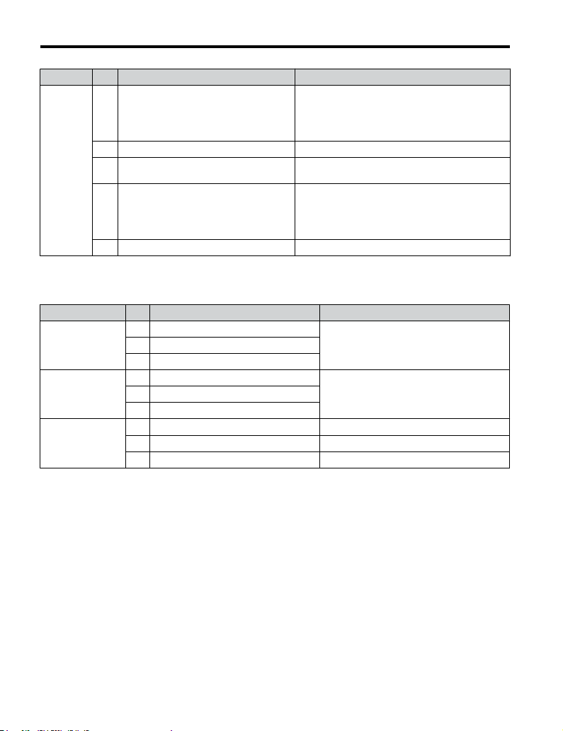
3.5 Control Circuit Wiring
Type No. Terminal Name (Function) Function (Signal Level) Default Setting
Response frequency: 0.5 to 32 kHz
Multi-function pulse train input (frequency
RP
reference)
Main
Frequency
Reference
Input
n
Multi-Function
Digital Output
Multi-Function
Photocoupler
Output
Monitor Output
<1> Do not assign functions to digital relay outputs that involve frequent switching. This may shorten relay
<2> Connect a suppression diode as shown in Figure 3.14 when driving a reactive load such as a relay coil. Ensure
<3> When set for sourcing. +5 V/1.5 kΩ or higher, +8 V/3.5 kΩ or higher, +10 V/10 kΩ or higher.
<4> When set for sinking, the external power supply should be +12 Vdc, ±5% with 16 mA or less.
+V Analog input power supply +10.5 Vdc (max allowable current 20 mA)
Multi-function analog input 1 (frequency
A1
reference)
Multi-function analog input 2 (frequency
A2
reference)
AC Frequency reference common 0 Vdc
Output Terminals
Table 3.7 Control Circuit Output Terminals
Type No. Terminal Name (Function) Function (Signal Level) Default Setting
MA N.O. (fault)
MB N.C. output (fault)
<1>
MC Digital output common
P1 Photocoupler output 1 (During run)
P2 Photocoupler output 2 (Frequency agree)
PC Photocoupler output common
MP Pulse train output (Output frequency)
AM Analog monitor output 0 to 10 Vdc (2 mA or less) Resolution: 1/1000
AC Monitor common 0 V
performance life. Switching life is estimated at 200,000 times (assumes 1 A, resistive load).
the diode rating is greater than the circuit voltage.
(Duty Cycle: 30 to 70%)
(High level voltage: 3.5 to 13.2 Vdc)
(Low level voltage: 0.0 to 0.8 Vdc)
(input impedance: 3 kΩ)
Input voltage 0 to +10 Vdc (20 kΩ) resolution 1/1000
Input voltage or input current (Selected by DIP switch
S1 and H3-01) 0 to +10 Vdc (20 kΩ),
Resolution: 1/1000
4 to 20 mA (250 Ω) or 0 to 20 mA (250 Ω),
Resolution: 1/500
Digital output
30 Vdc, 10 mA to 1 A; 250 Vac, 10 mA to 1 A
Minimum load: 5 Vdc, 10 mA (reference value)
Photocoupler output 48 Vdc, 2 to 50 mA
32 kHz (max)
<3> <4>
<2>
66
YASKAWA ELECTRIC TOEP C710606 14E YASKAWA AC Drive – V1000 Quick Start Guide
Page 67

3.5 Control Circuit Wiring
B
A
A – External power, 48 V max.
B – Suppression diode
Figure 3.14 Connecting a Suppression Diode
Serial Communication Terminals
n
Table 3.8 Control Circuit Terminals: Serial Communications
Type No. Signal Name Function (Signal Level)
R+ Communications input (+)
MEMOBUS/
Modbus
Communication
R- Communications input (-)
S+ Communications output (+)
S- Communications output (-)
IG Shield ground 0 V
C
D
C – Coil
D – 50 mA or less
MEMOBUS/Modbus
communication: Use a RS-485
or RS-422 cable to connect the
drive.
RS-485/422 MEMOBUS/
Modbus communication
protocol 115.2 kbps (max.)
Electrical Installation
3
YASKAWA ELECTRIC TOEP C710606 14E YASKAWA AC Drive – V1000 Quick Start Guide
67
Page 68

3.5 Control Circuit Wiring
u
Terminal Configuration
R+ R- S+ S- IG
P1 P2 PC A1 A2 +V AC AM AC MP
R+ R– S+ S– IG
P1 P2 PC A1 A2 +V AC AM AC MP
S1 S2 S3 S4 S5 S6 S7 HC SC H1 RP
S1 S2 S3 S4 S5 S6 S7 HC SC H1 RP
MCMBMA
MCMBMA
Figure 3.15 Removable Control Circuit Terminal Block
(CIMR-VAooooooo; CIMR-VUooooooo)
Wire Size and Torque Specifications
n
Select appropriate wire type and size from Table 3.9. For simpler and more reliable wiring,
crimp ferrules to the wire ends. Refer to Table 3.10 for ferrule terminal types and sizes.
68
YASKAWA ELECTRIC TOEP C710606 14E YASKAWA AC Drive – V1000 Quick Start Guide
Page 69

3.5 Control Circuit Wiring
Table 3.9 Wire Size and Torque Specifications (Same for All Models)
Tightening
Terminal
MA, MB,
MC
S1-S7,
SC, RP,
+V, A1,
A2, AC,
HC, H1,
P1, P2,
PC, MP,
AM, AC,
S+, S-, R
+, R-, IG
n
Screw
Torque
Size
M3 0.5 to 0.6 4.4 to 5.3
M2 0.22 to 0.25 1.9 to 2.2
N•m
Ferrule-Type Wire Terminations
Tightening
Torque
(in-lbs)
Bare Wire Terminal Ferrule-Type Terminal
Applic.
wire size
mm2 (AWG)
Stranded:
0.25 to 1.5
(24 to 16)
Single: 0.25
to 1.5
(24 to 16)
Stranded:
0.25 to 1.0
(24 to 18)
Single: 0.25
to 1.5
(24 to 16)
Recomm.
mm
(AWG)
0.75 (18)
0.75 (18)
2
Applic.
wire size
2
mm
(AWG)
0.25 to 1.0
(24 to 17)
0.25 to 0.5
(24 to 20)
Recomm.
2
mm
(AWG)
0.5 (20)
0.5 (20)
Wire
Type
Shielded
line, etc.
Crimp a ferrule to signal wiring to improve wiring simplicity and reliability. Use CRIMPFOX
ZA-3, a crimping tool manufactured by PHOENIX CONTACT.
d1
6 mm
L
Electrical Installation
d2
Figure 3.16 Ferrule Dimensions
Table 3.10 Ferrule Terminal Types and Sizes
2
Size mm
YASKAWA ELECTRIC TOEP C710606 14E YASKAWA AC Drive – V1000 Quick Start Guide
(AWG)
0.25 (24) AI 0.25-6YE 10.5 0.8 2.0
0.34 (22) AI 0.34-6TQ 10.5 0.8 2.0
0.5 (20) AI 0.5-6WH 12 1.1 2.5
0.75 (18) AI 0.75-6GY 12 1.3 2.8
1.0 AI 1-6RD 12 1.5 3.0
Type L (mm) d1 (mm) d2 (mm) Manufacturer
3
PHOENIX CONTACT
69
Page 70

3.5 Control Circuit Wiring
u
Wiring Procedure
This section describes the proper procedures and preparations for wiring the control terminals.
WARNING! Electrical Shock Hazard. Do not remove covers or touch the circuit boards while the power is on.
Failure to comply could result in death or serious injury.
NOTICE: Separate control circuit wiring from main circuit wiring (terminals R/L1, S/L2, T/L3, B1, B2, U/T1,
V/T2, W/T3, -, +1, +2) and other high-power lines. Improper wiring practices could result in drive malfunction
due to electrical interference.
NOTICE: Separate wiring for digital output terminals MA, MB and MC from wiring to other control circuit lines.
Improper wiring practices could result in drive or equipment malfunction or nuisance trips.
NOTICE: Use a class 2 power supply (UL standard) when connecting to the control terminals. Improper
application of peripheral devices could result in drive performance degradation due to improper power supply.
NOTICE: Insulate shields with tape or shrink tubing to prevent contact with other signal lines and equipment.
Improper wiring practices could result in drive or equipment malfunction due to short circuit.
NOTICE: Connect the shield of shielded cable to the appropriate ground terminal. Improper equipment
grounding could result in drive or equipment malfunction or nuisance trips.
Wire the control terminals using Figure 3.17 as a guide. Prepare the ends of the control circuit
wiring as shown inFigure 3.18. Refer to Wire Size and Torque Specifications on page 68.
NOTICE: Do not tighten screws beyond the specified tightening torque. Failure to comply may damage the
terminal block.
NOTICE: Use shielded twisted-pair cables as indicated to prevent operating faults. Improper wiring practices
could result in drive or equipment malfunction due to electrical interference.
Connect control wires as shown in the following figure:
70
YASKAWA ELECTRIC TOEP C710606 14E YASKAWA AC Drive – V1000 Quick Start Guide
Page 71

3.5 Control Circuit Wiring
D
Preparing wire
A
terminal ends
E
B
C
A – Control terminal block
B – Avoid fraying wire
strands when stripping
insulation from wire.
Strip length 5.5 mm.
C – Single wire or stranded
wire
Figure 3.17
Terminal Board Wiring Guide
F
A
B
A – Drive side
B – Connect shield to ground
terminal of drive.
C – Insulation
Figure 3.18 Preparing the Ends of Shielded Cables
YASKAWA ELECTRIC TOEP C710606 14E YASKAWA AC Drive – V1000 Quick Start Guide
D – Loosen screw to insert
wire.
E – Blade depth of 0.4 mm or
less
Blade width of 2.5 mm or
less
C
D
E
D – Control device side
E – Shield sheath (Insulate
with tape)
F – Shield
Electrical Installation
3
71
Page 72
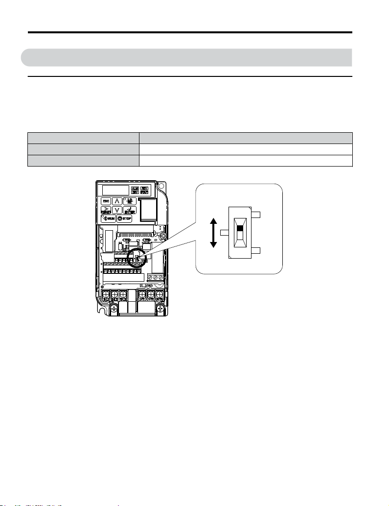
3.6 I/O Connections
3.6 I/O Connections
u
Sinking/Sourcing Mode Switch
Set the DIP switch S3 on the front of the drive to switch the digital input terminal logic between
sinking mode and sourcing mode; the drive is preset to sinking mode.
Table 3.11 Sinking/Sourcing Mode Setting
Set Value Details
SINK Sinking Mode (0 V common): default setting
SOURCE Sourcing Mode (+24 V common)
DIP Switch S3
SINK
SOURCE
Figure 3.19 DIP Switch S3
Transistor Input Signal Using 0 V Common/Sink Mode
n
When controlling the digital inputs by NPN transistors (0 V common/sinking mode), set the
DIP switch S3 to SINK and use the internal 24 V power supply.
72
YASKAWA ELECTRIC TOEP C710606 14E YASKAWA AC Drive – V1000 Quick Start Guide
Page 73

3.6 I/O Connections
SINK
Forward run/stop
SOURCE
Transistor Input Signal Using +24 V Common/Source Mode
n
Reverse run/stop
External fault N.O.
Fault reset
Multi-speed step 1
Multi-function input
Multi-speed step 2
Jog reference
Figure 3.20 Sinking Mode: Sequence from NPN Transistor (0 V Common)
Shielded cable
S1
S2
S3
S4
S5
S6
S7
SC
S3
Drive
SINK
SOURCE
+24V
When controlling digital inputs by PNP transistors (+24 V common/sourcing mode), set the
DIP switch S3 to SOURCE and use an external 24 V power supply.
Electrical Installation
3
YASKAWA ELECTRIC TOEP C710606 14E YASKAWA AC Drive – V1000 Quick Start Guide
73
Page 74

3.6 I/O Connections
SINK
SOURCE
External
power supply
+24 V
Figure 3.21 Source Mode: Sequence from PNP Transistor (+24 V Common)
Shielded cable
Forward run / stop
Reverse run / stop
External fault N.O.
Fault rest
Multi-step speed 1
Multi-function input
Multi-step speed 2
Jog frequency
S1
S2
S3
S4
S5
S6
S7
SC
S3
Drive
SINK
SOURCE
+24V
74
YASKAWA ELECTRIC TOEP C710606 14E YASKAWA AC Drive – V1000 Quick Start Guide
Page 75
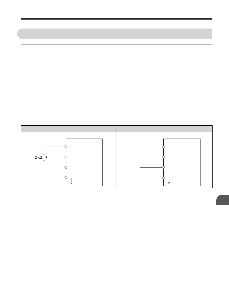
3.7 Main Frequency Reference
3.7 Main Frequency Reference
u
DIP Switch S1 Analog Input Signal Selection
The main frequency reference can either be a voltage or current signal input. For voltage
signals both analog inputs, A1 and A2, can be used, for current signals A2 must be used.
When using input A2 as a voltage input, set DIP switch S1 to “V” (left position) and program
parameter H3-09 to “0” (0 to +10 Vdc with lower limit) or “1” (0 to +10 Vdc without lower
limit).
To use current input at terminal A2, set the DIP switch S1 to "I" (default setting) and set
parameter H3-09 = “2” or “3” (4-20 mA or 0-20 mA). Set parameter H3-10 = “0” (frequency
reference).
Note: If Terminals A1 and A2 are both set for frequency reference (H3-02 = 0 and H3-10 = 0), the addition of
both input values builds the frequency reference.
Table 3.12 Frequency Reference Configurations
Voltage Input Current Input
0 to 10 V
Drive
+10.5 V
+V
20 mA current
Main speed
frequency reference
A1
(voltage input)
Main speed
A2
frequency reference
(current input)
AC
Frequency reference
common
4 to 20 mA input
or
0 to 20 mA input
Drive
+10.5 V
+V
20 mA current
Main speed
A1
frequency reference
(voltage input)
Main speed
A2
frequency reference
(current input)
AC
Frequency reference
common
Electrical Installation
YASKAWA ELECTRIC TOEP C710606 14E YASKAWA AC Drive – V1000 Quick Start Guide
3
75
Page 76
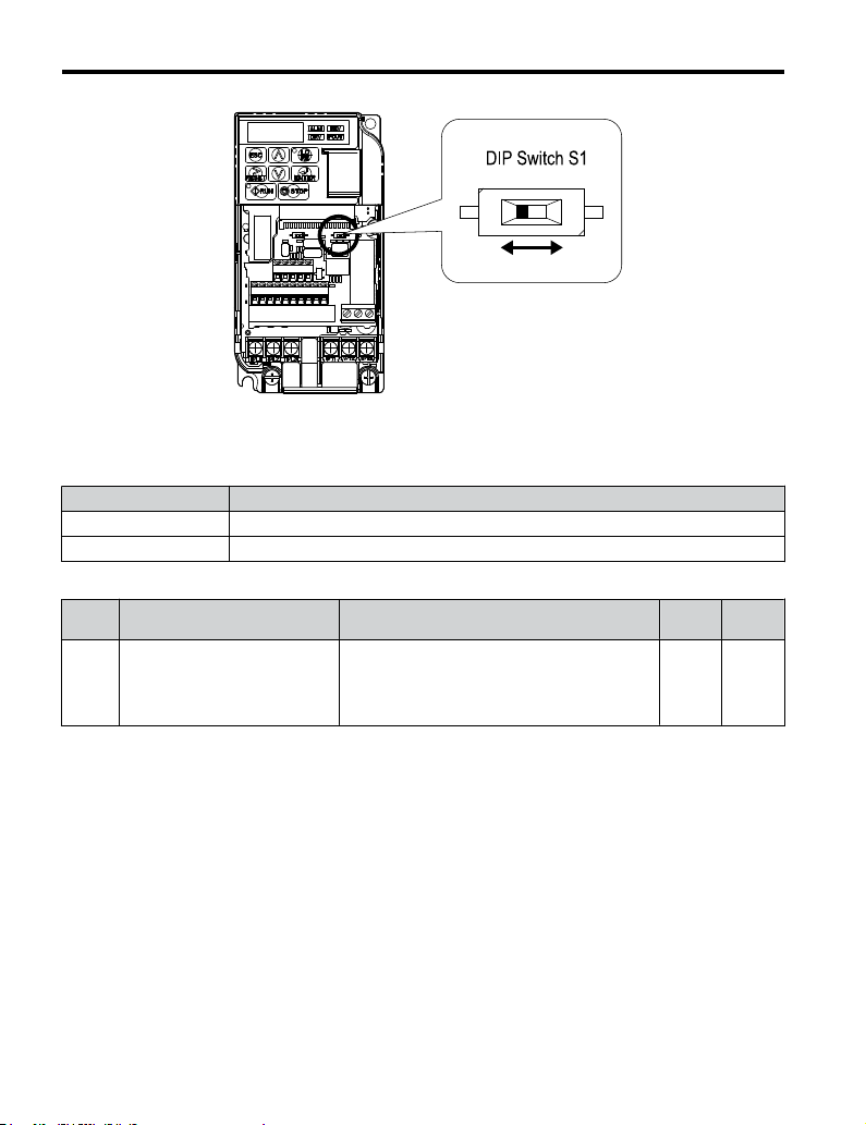
3.7 Main Frequency Reference
V I
Figure 3.22 DIP Switch S1
Table 3.13 DIP Switch S1 Settings
Setting Value Description
V (left position) Voltage input (0 to 10 V)
I (right position) Current input (4 to 20 mA or 0 to 20 mA): default setting
Table 3.14 Parameter H3-09 Details
No. Parameter Name Description
Selects the signal level for terminal A2.
Frequency ref. (current)
H3-09
terminal A2 signal level selection
0: 0 to +10 V, unipolar input (with lower limit)
1: 0 to +10 V, bipolar input (no lower limit)
2: 4 to 20 mA
3: 0 to 20 mA
Setting
Range
0 to 3 2
Default
Setting
76
YASKAWA ELECTRIC TOEP C710606 14E YASKAWA AC Drive – V1000 Quick Start Guide
Page 77

3.8 Wiring Checklist
No. Item Page
Drive, peripherals, option cards
1 Check drive model number to ensure receipt of correct model. 26
2 Check for correct braking resistors, DC reactors, noise filters, and other peripheral devices. -
3 Check for correct option card model. -
Installation area and physical setup
4 Ensure area surrounding the drive complies with specifications. 38
Power supply voltage, output voltage
The voltage from the power supply should fall within the input voltage specification range
5
of the drive.
6 The voltage rating for the motor should match the drive output specifications. 26
Main circuit wiring
7 Confirm proper branch circuit protection exists per National and Local codes. 50
8 Properly wire the power supply to drive terminals R/L1, S/L2 and T/L3.
Properly wire the drive and motor together.
The motor lines and drive output terminals R/T1, V/T2 and W/T3 should match in order
9
to produce the desired phase order. If the phase order is incorrect, the drive will rotate in
the opposite direction.
10 Use 600 Vac vinyl-sheathed wire for the power supply and motor lines. 59
Use the correct wire gauges for the main circuit. Refer to Table 3.2 , Table 3.3, or Table
11
3.4.
• When using comparatively long motor cable, calculate the amount of voltage drop.
Motor rated voltage (V) x 0.02 ≥
3 x voltage resistance (Ω/km) x cable length (m) x motor rated current (A) x 10
3.8 Wiring Checklist
166
-
62
59
59
-3
Electrical Installation
3
YASKAWA ELECTRIC TOEP C710606 14E YASKAWA AC Drive – V1000 Quick Start Guide
• If the cable between the drive and motor exceeds 50 m, adjust the carrier frequency
(C6-02) accordingly.
12 Properly ground the drive. Review page 63. 63
Tightly fasten all terminal screws (control circuit terminals, grounding terminals). Refer
13
to Table 3.2, Table 3.3, or Table 3.4
.
63
59
77
Page 78

3.8 Wiring Checklist
No. Item Page
Set up overload protection circuits when running multiple motors from a single drive.
14
Note: Close MC1 through MCn before operating the drive.
If using a braking resistor or dynamic braking resistor unit, install a magnetic contactor.
15
Properly install the resistor, and ensure that overload protection shuts off the power supply. -
16 Verify phase advancing capacitors are NOT installed on the output side of the drive. -
17 Use twisted-pair cables for all drive control circuit wiring. 65
18
Ground the shields of shielded wiring to the GND terminal.
If using a 3-Wire sequence, properly set parameters for multi-function contact input
19
terminals S1 through S7, and properly wire control circuits.
20 Properly wire any option cards. -
Check for any other wiring mistakes.
21
Only use a multimeter to check wiring.
Properly fasten the control circuit terminal screws in the drive. Refer to Table 3.2, Table
22
3.3, or Table 3.4.
23 Pick up all wire clippings. -
Ensure that no frayed wires on the terminal block are touching other terminals or
24
connections.
25 Properly separate control circuit wiring and main circuit wiring. -
26 Analog signal line wiring should not exceed 50 m. -
27 Safe Disable Input wiring should not exceed 30 m. -
Power supply
Drive
Control circuit wiring
MC1
MC2
MCn
MC1 - MCn
OL 1 - OLn
OL1
M1
OL2
M2
OLn
Mn
... magnetic contactor
... thermal relay
-
70
52
-
59
-
78
YASKAWA ELECTRIC TOEP C710606 14E YASKAWA AC Drive – V1000 Quick Start Guide
Page 79

4
Start-Up
Programming &
Operation
This chapter explains the functions of the LED operator and how
to program the drive for initial operation.
4.1 USING THE DIGITAL LED OPERATOR..............80
4.2 THE DRIVE AND PROGRAMMING MODES.......84
4.3 START-UP FLOWCHARTS................................87
4.4 POWERING UP THE DRIVE...............................92
4.5 APPLICATION SELECTION...............................93
4.6 BASIC DRIVE SETUP ADJUSTMENTS............102
4.7 AUTO-TUNING................................................109
4.8 NO-LOAD OPERATION TEST RUN..................118
4.9 TEST RUN WITH LOAD CONNECTED.............120
4.10 TEST RUN CHECKLIST...................................121
YASKAWA ELECTRIC TOEP C710606 14E YASKAWA AC Drive – V1000 Quick Start Guide
79
Page 80

STOP
4.1 Using the Digital LED Operator
4.1 Using the Digital LED Operator
Use the LED operator to enter run and stop commands, display data, edit parameters, as well
as display fault and alarm information.
u
Keys, Displays, and LEDs
13
1
5
2
12
11
9
3
15
14
10
STOP
V1000
WARNING
Read manual before installing.
Wait 1 minute for capacitor discharge after
disconnecting power supply.
To conform to requirements, make sure to
ground the supply neutral for 400V class.
80
Fref
FWD/REV Sel
Fout
lout
Mon1
Monitor
Verify
SetUpGuide
Program
Auto-Tuning
Risk of electric shock.
4 6
(Hz)
:
:
(Hz)
:
(A)
:
(V)
:
:
:
:
:
:
YASKAWA ELECTRIC TOEP C710606 14E YASKAWA AC Drive – V1000 Quick Start Guide
7
8
Page 81
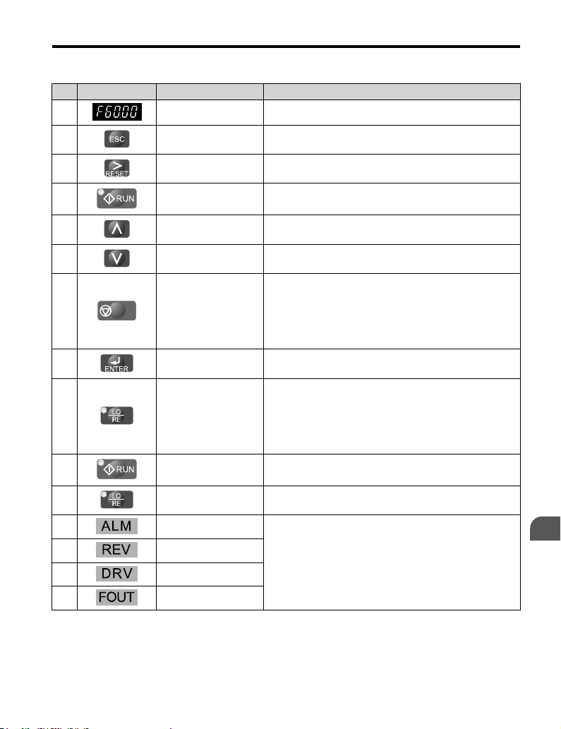
4.1 Using the Digital LED Operator
Table 4.1 Keys and Displays on the LED Operator
No. Display Name Function
1 Data Display Area Displays the frequency reference, parameter number, etc.
2 ESC Key Returns to the previous menu.
3 RESET Key
4 RUN Key Starts the drive.
5 Up Arrow Key Scrolls up to select parameter numbers, setting values, etc.
6 Down Arrow Key Scrolls down to select parameter numbers, setting values, etc.
7
8 ENTER Key
9 LO/RE Selection Key
10 RUN Light Lit while the drive is operating the motor.
11 LO/RE Light Lit while the operator (LOCAL) is selected to run the drive.
12 ALM LED Light
13 REV LED Light
14 DRV LED Light
15 FOUT LED Light
STOP
STOP Key
Moves the cursor to the right.
Resets the drive to clear a fault situation.
Stops the drive.
Note: Stop priority circuit. A fast-stop is available by pressing
the STOP key when the drive detects a danger even if the drive
is running by a signal from the multi-function contact input
terminal (REMOTE is set). To avoid stoppage by using the
STOP key, set o2-02 (STOP Key Function Selection) to 0
(Disabled).
Selects all modes, parameters, settings, etc.
Selects a menu item to move from one display screen to the next.
Switches drive control between the operator (LOCAL) and the
control circuit terminals (REMOTE).
Note: LOCAL/REMOTE key effective during stop in drive
mode. If the digital operator could change from REMOTE to
LOCAL by incorrect operation, set o2-01 (LOCAL/REMOTE
Key Function Selection) to “0” (disabled) to disable LOCAL/
REMOTE key.
Refer to LED Screen Displays on page 82.
Start-Up Programming
& Operation
4
YASKAWA ELECTRIC TOEP C710606 14E YASKAWA AC Drive – V1000 Quick Start Guide
81
Page 82

4.1 Using the Digital LED Operator
u
LED Screen Displays
Display Lit Flashing Off
• When an alarm occurs
When the drive detects an alarm
or error
Motor is rotating in reverse — Motor is rotating forward
Drive Mode
Auto-Tuning
Displays output frequency (Hz) — —
As illustrated
in this
manual
<1> Refer to the DriveWorksEZ instruction manual for further information.
u
LO/RE LED and RUN LED Indications
LED Lit Flashing Flashing Quickly Off
When run command is
selected from LED
operator (LOCAL)
• During deceleration to
During run
• When a run command
• oPE detected
• When a fault or error occurs
during Auto-Tuning
When DriveWorksEZ is used
— —
stop
is input and frequency
reference is 0
<1>
• During deceleration
at a fast-stop.
• During deceleration
• During stop by
interlock operation.
Normal state (no fault or alarm)
Programming Mode
Run command is selected
from device other than LED
operator (REMOTE)
During stop
As shown
82
YASKAWA ELECTRIC TOEP C710606 14E YASKAWA AC Drive – V1000 Quick Start Guide
Page 83
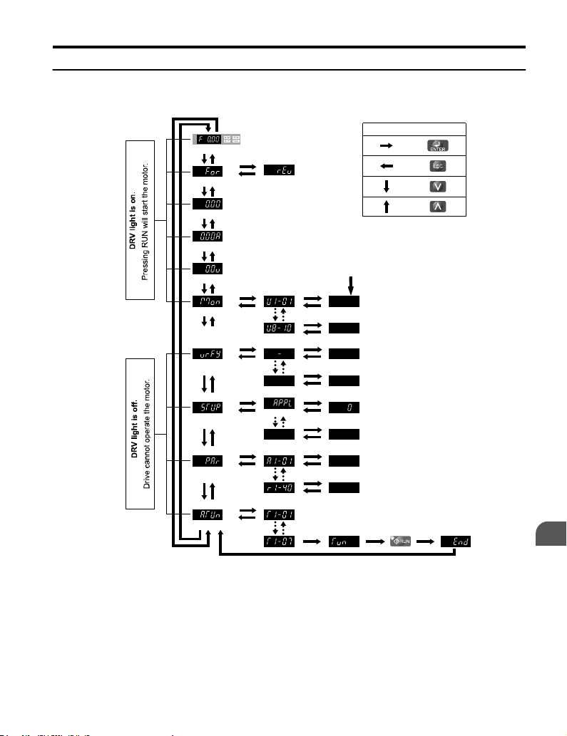
u
Menu Structure for Digital LED Operator
Turn the power on
Forward Selection
Output Frequency
Output Current
DRIVE MODE
Output Voltage
Monitor Display
Note: “XX” characters are shown in this manual.
The drive will display the actual setting values.
<1>
Reverse Selection
4.1 Using the Digital LED Operator
Description of Key Operations
:
:
:
:
XX
XX
Verify Menu
Set Up Mode
Parameter Setting Mode
XXXX
XX
XX
Application Preset
XX
XX
XX
XX
XX
XX
XX
XX
X
PROGRAMMING MODE
Auto-Tuning
XX
Figure 4.1 Digital LED Operator Screen Structure
<1> Reverse can only be selected when LOCAL is set.
YASKAWA ELECTRIC TOEP C710606 14E YASKAWA AC Drive – V1000 Quick Start Guide
Start-Up Programming
& Operation
4
83
Page 84

4.2 The Drive and Programming Modes
4.2 The Drive and Programming Modes
The drive functions are divided into two main groups accessible via the Digital LED Operator:
Drive Mode: The Drive mode allows motor operation and parameter monitoring. Parameter
settings cannot be changed when accessing functions in the Drive Mode.
Programming Mode: The Programming Mode allows access to setup/adjust, verify
parameters and Auto-Tuning. The drive prohibits changes in motor operation such as start/
stop when the Digital LED Operator is accessing a function in the Programming Mode.
u
Changing Parameter Settings or Values
This example explains changing C1-01 (Acceleration Time 1) from 10.0 seconds (default) to
20.0 seconds.
Step Display/Result
1. Turn on the power to the drive. The initial display appears.
2.
Press the key until the Setup Mode Screen appears.
3.
Press the key to view the parameter setting display.
4.
Scroll through parameters by pressing the key until C1-01
appears.
5.
Press to view the current setting value (10.0). (Number
farthest to the left flashes)
6.
Press until the desired number is selected. (“1” flashes)
7.
Press the key and enter 0020.0.
8.
Press and the drive will confirm the change.
9. The display automatically returns to the screen shown in Step 4.
10.
Press the key until back at the initial display.
84
YASKAWA ELECTRIC TOEP C710606 14E YASKAWA AC Drive – V1000 Quick Start Guide
Page 85

STOP
4.2 The Drive and Programming Modes
u
Switching Between LOCAL and REMOTE
Entering the run command using the LED operator is referred to as LOCAL, while entering
the run command from an external device via the control circuit terminals or network option
card is referred to as REMOTE.
WARNING! Sudden Movement Hazard. The drive may start unexpectedly if the Run command is already
applied when switching from LOCAL mode to REMOTE mode when b1-07 = 1, resulting in death or serious
injury. Be sure all personnel are clear of rotating machinery and electrical connections prior to switching
between LOCAL mode and REMOTE mode.
There are two ways to switch between LOCAL and REMOTE.
Note: 1. After selecting LOCAL, the LO/RE light will remain lit.
2. The drive will not allow the user to switch between LOCAL and REMOTE during run.
Using the LO/RE Key on the LED Operator
n
Step Display/Result
1. Turn on the power to the drive. The initial display appears.
Press . The LO/RE light will light up. The drive is now in
2.
Local.
To set the drive for REMOTE operation, press the key again.
Using Input Terminals S1 through S7 to Switch between LO/RE
n
Switch between LOCAL and REMOTE using one of the digital input terminals S1 through
S7 (set the corresponding parameter H1-01 through H1-07 to “1”).
Follow the example below to set the digital input terminals.
Note: 1. For a list of digital input selections, Refer to Parameter List on page 157.
2. Setting a multi-function input terminal to a value of 1 disables the LO/RE key on the LED operator.
u
Parameters Available in the Setup Group
Setup Mode (STUP)
n
Parameters used for this drive are classified into A to U. To simplify the drive setup, frequently
used parameters are selected and input into Setup Mode.
YASKAWA ELECTRIC TOEP C710606 14E YASKAWA AC Drive – V1000 Quick Start Guide
Start-Up Programming
& Operation
4
85
Page 86

4.2 The Drive and Programming Modes
To set a parameter, the Setup Mode must be displayed first. Press the Up/Down key
1.
until is displayed.
Select the parameter and change the setting. Table 4.2 lists parameters available in
2.
the Setup group. If the desired parameter cannot be set in the Setup mode, use the
Parameter Setting mode.
Note: When parameter A1-02 (Control Method Selection) is changed, some parameter set values are also changed
automatically.
Note: Use the “Par” menu in the Programming mode to access parameters not listed in the Setup Group.
Note: Display parameters depend on A1-06. Refer to Application Selection on page 93.
Table 4.2 Setup Group Parameters
Parameter Name
A1-02 Control Method Selection
b1-01 Frequency Reference Selection 1
b1-02 Run Command Selection 1
b1-03 Stop Method Selection
C1-01 Acceleration Time 1
C1-02 Deceleration Time 1
C6-01 Duty Selection
C6-02 Carrier Frequency Selection
d1-01 Frequency Reference 1
d1-02 Frequency Reference 2
d1-03 Frequency Reference 3
d1-04 Frequency Reference 4
d1-17 Jog Frequency Reference
E1-01 Input Voltage Reference
Parameter Name
E1-03 V/f Pattern Selection
E1-04 Maximum Output Frequency
E1-05 Maximum Voltage
E1-06 Base Frequency
E1-09 Minimum Output Frequency
E1-13 Base Voltage
E2-01 Motor Rated Current
E2-04 Number of Motor Poles
E2-11 Motor Rate Capacity
H4-02 Terminal AM Gain Setting
L1-01 Motor Protection Function Selection
L3-04
Stall Prevention Selection during
Deceleration
86
YASKAWA ELECTRIC TOEP C710606 14E YASKAWA AC Drive – V1000 Quick Start Guide
Page 87

4.3 Start-up Flowcharts
4.3 Start-up Flowcharts
The flowcharts in this section summarize basic steps required to start the drive. Use the
flowcharts to determine the most appropriate start-up method for a given application. The
charts are intended as a quick reference to help familiarize the user with start-up procedures.
Flowchart Subchart Objective Page
A Basic startup procedure and motor tuning. 88
A-1 Simple motor setup with Energy Savings or Speed Search using V/f mode. 89
High-performance operation using Open Loop Vector (OLV) motor
A-2
control.
A-3 Operation with Permanent Magnet (PM) motors. 91
Setup of drive using application specific selections. Refer to Application
-
Selection on page 93.
90
-
YASKAWA ELECTRIC TOEP C710606 14E YASKAWA AC Drive – V1000 Quick Start Guide
Start-Up Programming
& Operation
4
87
Page 88

4.3 Start-up Flowcharts
u
Flowchart A: Basic Start-up and Motor Tuning
Figure 4.2, Flowchart A, describes basic start-up sequence for the drive and motor system.
This sequence varies slightly depending on application. Use drive default parameter settings
in simple applications that do not require high precision.
START
Install and wire the drive as explained in Chapters 1, 2, and 3
Adhere to safety messages concerning application of power
Apply main power on to the drive
Application Presets
A1-06 used ?
No
Set the control mode in parameter A1-02.
* b1-01/02 for frequency reference and run command source selection
* H1-oo,H2-oo,H3-oo,H4-oo,H6-o ofor I/O terminal setting
* d1-oo for multi-speed references if used
* C1-oo and C2-oo
* C6-01 for heavy/normal duty mode selection
* L3-04 if braking options are used
0: V/f control
To
Flowchart A-1
Set the basic parameters
for accel./decel. and S-curve time settings
Control Mode
A1-02 =
2: Open Loop
To
Flowchart A-2
Vector control
Yes
5: Open Loop Vector for PM motors
To
Flowchart A-3
From Flowchart A-1, A-2, or A-3
Run the motor without load; check the rotation direction and operation.
Verify external signal commands to the drive work as desired.
Couple the load or machine to the motor. Run the machine and check for desired operation.
Fine tune parameters. Adjust application settings (PID, ...) if necessary.
Check the machine operation and verify parameter settings.
Drive is ready to run the application.
Figure 4.2 Basic Start-Up and Motor Tuning
TO
Refer to
Application
Selection section
FROM
88
YASKAWA ELECTRIC TOEP C710606 14E YASKAWA AC Drive – V1000 Quick Start Guide
Page 89

4.3 Start-up Flowcharts
u
Subchart A1: Simple Motor Setup with Energy Savings or Speed Search Using V/f Mode
Figure 4.3, Flowchart A1, describes simple motor setup for V/f control. V/f Motor Control
is suited for the most basic applications such as fans or pumps. This procedure illustrates using
Energy Savings and Speed Estimation Speed Search. V/f control can be used where rotational
auto-tuning cannot be performed.
From
Flowchart
A
Set or verify the V/f pattern settings E1-oo.
Energy Savings
(b8-01=1)
or
Speed Estimation
Speed Search (b3-24=1)
NO
Is the motor cable
longer than 50 m?
YES
Perform Stationary Auto-Tuning for
terminal resistance (T1-01 = 2)
enabled ?
NO
YES
Perform Rotational Auto-Tuning
for V/f Control
(T1-01 = 3)
Return to
Flowchart
A
Figure 4.3 Simple Motor Setup with Energy Savings or Speed Search Using V/f Mode
YASKAWA ELECTRIC TOEP C710606 14E YASKAWA AC Drive – V1000 Quick Start Guide
Start-Up Programming
& Operation
4
89
Page 90

4.3 Start-up Flowcharts
u
Subchart A2: High Performance Operation Using Open Loop Vector Motor Control
Figure 4.4, Flowchart A2, describes Open Loop Vector Control for high-performance motor
operation. This is appropriate for applications requiring high starting torque, torque limits,
and improved speed regulation.
From
Flowchart
A
NO YES
Motor test report/ data
sheet available?
YES
Enter the data from the motor data
sheet to E2-oo parameters.
Is the motor cable
longer than 50 m?
NO
Possible for motor to
rotate during tuning? <1>
<1>
Return to
A
Rotational tuning should
be performed with the
load disconnected
NO
Calculate necessary E2-oo
parameter data using the
nameplate information.
YES
Perform Stationary Auto-Tuning for
terminal resistance (T1-01 = 2)
Flowchart
Perform Rotating Auto-
Tuning (T1-01 = 0)
Figure 4.4 Flowchart A2: High Performance Operation Using Open Loop Vector Motor
Control
90
YASKAWA ELECTRIC TOEP C710606 14E YASKAWA AC Drive – V1000 Quick Start Guide
Page 91

4.3 Start-up Flowcharts
u
Subchart A3: Operation with Permanent Magnet Motors
Figure 4.5, Flowchart A3, describes tuning for PM motors in Open Loop Vector Control. PM
motors can be used for energy savings in reduced or variable torque applications.
From
Flowchart
A
Motorcode is known ?
YES
For parameter E5-01
(for Yaskawa PM Motors)
NO
Enter “FFFF” to parameter
E5-01
Set the motor code to
parameter E5-01
Return to
Flowchart
A
Figure 4.5 Operation with Permanent Magnet Motors
YASKAWA ELECTRIC TOEP C710606 14E YASKAWA AC Drive – V1000 Quick Start Guide
Enter the motor data into
parameters E5-02 to E5-24
Start-Up Programming
& Operation
4
91
Page 92

4.4 Powering Up the Drive
4.4 Powering Up the Drive
u
Powering Up the Drive and Operation Status Display
Powering Up the Drive
n
Review the following checklist before turning the power on.
Item to Check Description
Ensure the power supply voltage is correct:
200 V class: single-phase 200 to 240 Vac 50/60 Hz
200 V class: 3-phase 200 to 240 Vac 50/60 Hz
Power supply voltage
Drive output terminals
and motor terminals
Control circuit
terminals
Drive control terminal
status
Status of the load
and connected
machinery
Status Display
n
When the power supply to the drive is turned on, the LED operator lights will appear as
follows:
No. Name Description
Normal
Operation
400 V class: 3-phase 380 to 480 Vac 50/60 Hz
Properly wire the power supply input terminals (R/L1, S/L2, T/L3).
(for single-phase 200 V class models, wire only R/L1 and S/L2)
Check for proper grounding of drive and motor.
Properly wire drive output terminals U/T1, V/T2, and W/T3 with motor terminals U, V,
and W.
Check control circuit terminal connections.
Open all control circuit terminals (off).
Uncouple the motor from the load.
The data display area displays the frequency reference. is lit.
Fault
Main circuit low voltage (ex)
Note: Display will vary depending on drive settings.
92
YASKAWA ELECTRIC TOEP C710606 14E YASKAWA AC Drive – V1000 Quick Start Guide
Data displayed varies by the type of fault. Refer to Fault Displays,
Causes, and Possible Solutions on page 125 for more information and
possible solution. and are lit.
Page 93

4.5 Application Selection
4.5 Application Selection
Several Application Presets are available to facilitate drive setup for commonly used
applications. Selecting one of these Application Presets automatically sets the required
parameters to the Application Preset default values and selects I/Os. In addition, the
parameters most likely to be changed are assigned to the list of User Parameters, A2-01
through A2-16. These can be accessed in the Setup Mode and provide quicker application
adjustment by eliminating the need to scroll through multiple menus.
The following presets can be selected:
Note: 1. The drive parameters should be initialized by setting A1-03 to “2220” or “3330” prior to selecting an
WARNING! Confirm the drive I/O signals and external sequence before performing a test run. Setting
parameter A1-06 may change the I/O terminal function automatically from the default setting. Failure to comply
may result in death or serious injury.
No. Parameter Name Setting Range Default
A1-06 Application Preset
<1> Application Preset settings 6 and 7 are only available in software versions 5010, 1010, and 1011. To determine
Application Preset.
2. Once an Application Preset has been selected, a different Application Preset cannot be selected again
until A1-03 is assigned to 2220 or 3330 (2-wire initialization or 3-wire initialization).
0: Disabled
1: Water supply pump
2: Conveyor
3: Exhaust fan
4: HVAC
5: Compressor
<1>
the drive software version, refer to the PRG: field on the drive nameplate or drive parameter U1-25.
0
u
Setting 1: Water Supply Pump Application
Table 4.3 Water Supply Pump Parameter Settings
No. Name Default Setting
A1-02 Control Method Selection 0: V/f Control
b1-04 Reverse Operation Selection 1: Reverse Prohibited
C1-01 Acceleration Time 1 1.0 s
C1-02 Deceleration Time 1 1.0 s
C6-01 Duty Rating 1: Normal Duty
E1-03 V/f Pattern Selection 0FH
E1-07 Mid Output Frequency 30.0 Hz
YASKAWA ELECTRIC TOEP C710606 14E YASKAWA AC Drive – V1000 Quick Start Guide
Start-Up Programming
& Operation
4
93
Page 94

4.5 Application Selection
No. Name Default Setting
E1-08 Mid Output Frequency Voltage 50.0 V
L2-01 Momentary Power Loss Operation Selection 1: Enabled
L3-04
No. Parameter Name No. Parameter Name
b1-01 Frequency Reference Selection E1-08 Mid Output Frequency Voltage
b1-02 Run Command Selection E2-01 Motor Rated Current
b1-04 Reverse Operation Selection H1-05
C1-01 Acceleration Time 1 H1-06
C1-02 Deceleration Time 1 H1-07
E1-03 V/f Pattern Selection L5-01 Number of Auto Restart Attempts
E1-07 Mid Output Frequency − −
u
A1-02 Control Method Selection 0: V/f Control
C1-01 Acceleration Time 1 3.0 s
C1-02 Deceleration Time 1 3.0 s
C6-01 Duty Rating 0: Heavy Duty
L3-04
Stall Prevention Selection during
Deceleration
Table 4.4 Water Supply Pump: User Parameters (A2-01 to A2-16)
1: Enabled
Multi-Function Digital Input Terminal
S5 Function Selection
Multi-Function Digital Input Terminal
S6 Function Selection
Multi-Function Digital Input Terminal
S7 Function Selection
Setting 2: Conveyor Application
Table 4.5 Conveyor: Parameter Settings
No. Parameter Name Default Setting
Stall Prevention Selection during
Deceleration
1: Enabled
Table 4.6 Conveyor: User Parameters (A2-01 to A2-16)
No. Parameter Name No. Parameter Name
A1-02 Control Method Selection C1-02 Deceleration Time 1
b1-01 Frequency Reference Selection E2-01 Motor Rated Current
b1-02 Run Command Selection L3-04
94
YASKAWA ELECTRIC TOEP C710606 14E YASKAWA AC Drive – V1000 Quick Start Guide
Stall Prevention Selection during
Deceleration
Page 95

4.5 Application Selection
No. Parameter Name No. Parameter Name
C1-01 Acceleration Time 1 − −
u
Setting 3: Exhaust Fan Application
Table 4.7 Exhaust Fan: Parameter Settings
No. Parameter Name Default Setting
A1-02 Control Method Selection 0: V/f Control
b1-04 Reverse Operation Selection 1: Reverse Prohibited
C6-01 Duty Selection 1: Normal Duty
E1-03 V/f Pattern Selection 0FH
E1-07 Mid Output Frequency 30.0 Hz
E1-08 Mid Output Frequency Voltage 50.0 V
L2-01 Momentary Power Loss Operation Selection 1: Enabled
L3-04
No. Parameter Name No. Parameter Name
b1-01 Frequency Reference Selection E1-07 Mid Output Frequency
b1-02 Run Command Selection E1-08 Mid Output Frequency Voltage
b1-04 Reverse Operation Selection E2-01 Motor Rated Current
b3-01 Speed Search Selection at Start H1-05
C1-01 Acceleration Time 1 H1-06
C1-02 Deceleration Time 1 H1-07
E1-03 V/f Pattern Selection L5-01 Number of Auto Restart Attempts
Stall Prevention Selection during
Deceleration
Table 4.8 Exhaust Fan: User Parameters (A2-01 to A2-16)
1: Enabled
Multi-Function Digital Input Terminal
S5 Function Selection
Multi-Function Digital Input Terminal
S6 Function Selection
Multi-Function Digital Input Terminal
S7 Function Selection
Start-Up Programming
& Operation
4
YASKAWA ELECTRIC TOEP C710606 14E YASKAWA AC Drive – V1000 Quick Start Guide
95
Page 96

4.5 Application Selection
u
Setting 4: HVAC Fan Application
Table 4.9 HVAC Fan: Parameter Settings
No. Parameter Name Default Setting
A1-02 Control Method Selection 0: V/f Control
b1-04 Reverse Operation Selection 1: Reverse Prohibited
C6-01 Duty Rating 1: Normal Duty
C6-02 Carrier Frequency Selection 3: 8.0 kHz
H2-03 Terminals P2 Function Selection 39: Watt Hour Pulse Output
L2-01
L8-03 Overheat Pre-Alarm Operation Selection 4: Operation at lower speed
L8-38 Carrier Frequency Reduction 2: Enabled across entire frequency range.
No. Parameter Name No. Parameter Name
b1-01 Frequency Reference Selection E1-03 V/f Pattern Selection
b1-02 Run Command Selection E1-04 Max Output Frequency
b1-04 Reverse Operation Selection E2-01 Motor Rated Current
C1-01 Acceleration Time 1 H3-11 Terminal A2 Gain Setting
C1-02 Deceleration Time 1 H3-12 Terminal A2 Input Bias
C6-02 Carrier Frequency Selection L2-01
d2-01 Frequency Reference Upper Limit L8-03 Overheat Pre-Alarm Operation Selection
d2-02 Frequency Reference Lower Limit o4-12 kWh Monitor Initial Value Selection
Momentary Power Loss Operation
Selection
Table 4.10 HVAC Fan: User Parameters (A2-01 to A2-16)
2: CPU Power Active - Drive will restart if
power returns prior to control power supply
shut down.
Momentary Power Loss Operation
Selection
u
Setting 5: Compressor Application
Table 4.11 Compressor: Parameter Settings
No. Parameter Name Default Setting
A1-02 Control Method Selection 0: V/f Control
b1-04 Reverse Operation Selection 1: Reverse Prohibited
C1-01 Acceleration Time 1 5.0 s
C1-02 Deceleration Time 1 5.0 s
96
YASKAWA ELECTRIC TOEP C710606 14E YASKAWA AC Drive – V1000 Quick Start Guide
Page 97

4.5 Application Selection
No. Parameter Name Default Setting
C6-01 Duty Rating 0: Heavy Duty
E1-03 V/f Pattern Selection 0FH
L2-01 Momentary Power Loss Operation Selection 1: Enabled
L3-04
No. Parameter Name No. Parameter Name
b1-01 Frequency Reference Selection E1-03 V/f Pattern Selection
b1-02 Run Command Selection E1-07 Mid Output Frequency
b1-04 Reverse Operation Selection E1-08 Mid Output Frequency Voltage
C1-01 Acceleration Time 1 E2-01 Motor Rated Current
C1-02 Deceleration Time 1 − −
u
Note: 1. Read the instructions listed in on 98 when using Application Preset 6
No. Parameter Name Default Setting
A1-02 Control Method Selection 2: Open Loop Vector Control
b1-01 Frequency Reference Selection 0: Operator
b6-01 Dwell Reference at Start 3.0 Hz
b6-02 Dwell Time at Start 0.3 s
C1-01 Acceleration Time 1 3.0 s
C1-02 Deceleration Time 1 3.0 s
C6-01 Duty Rating 0: Heavy Duty
C6-02 Carrier Frequency Selection 2: 5 kHz
d1-01 Frequency Reference 1 6.0 Hz
d1-02 Frequency Reference 2 30.0 Hz
d1-03 Frequency Reference 3 60.0 Hz
Stall Prevention Selection during
Deceleration
Table 4.12 Compressor: User Parameters (A2-01 to A2-16):
1: Enabled
Setting 6: Preset 6
2. Perform Auto-Tuning after selecting Application Preset 6.
3. If UL3 appears on the operator display after Auto-Tuning is complete, set L6-01 to “0” to repeat the
Auto-Tuning process.
Table 4.13 Preset 6: Parameters and Settings
Start-Up Programming
& Operation
4
YASKAWA ELECTRIC TOEP C710606 14E YASKAWA AC Drive – V1000 Quick Start Guide
97
Page 98

4.5 Application Selection
No. Parameter Name Default Setting
E1-03 V/f Pattern Selection 0FH
H2-02 Terminals P1 Function Selection 37: During Frequency Output
H2-03 Terminals P2 Function Selection 5: Frequency Detection 2
L2-03
L3-04
L4-01 Speed Agreement Detection Level 2.0 Hz
L4-02 Speed Agreement Detection Width 0.0 Hz
L6-01 Torque Detection Selection 1 8: UL3 at RUN - Fault
L6-02 Torque Detection Level 1 5%
L6-03 Torque Detection Time 1 0.5 s
L8-05 Input Phase Loss Protection Selection
L8-07 Output Phase Loss Protection 1: Enabled
L8-38 Carrier Frequency Reduction 1: Enabled below 6 Hz
L8-41 Current Alarm Selection 1: Enabled (alarm is output)
<1> Disable L8-05 for single-phase models.
No. Parameter Name No. Parameter Name
A1-02 Control Method Selection d1-02 Frequency Reference 2
b1-01 Frequency Reference Selection d1-03 Frequency Reference 3
b6-01 Dwell Reference at Start E1-08 Mid Output Frequency Voltage
b6-02 Dwell Time at Start H2-01
C1-01 Acceleration Time 1 L1-01 Motor Overload Protection Selection
C1-02 Deceleration Time 1 L4-01 Speed Agreement Detection Level
C6-02 Carrier Frequency Selection L6-02 Torque Detection Level 1
d1-01 Frequency Reference 1 L6-03 Torque Detection Time 1
Momentary Power Loss Minimum
Baseblock Time
Momentary Power Loss Voltage Recovery
Ramp Time
Table 4.14 Preset 6: User Parameters (A2-01 to A2-16):
0.3 s
0: Disabled
1: Enabled
<1>
Terminals MA, MB, and MC Function
Selection
u
Notes on Controlling the Brake when Using Application Preset 6
The frequency detection function is used for controlling the brake.
98
YASKAWA ELECTRIC TOEP C710606 14E YASKAWA AC Drive – V1000 Quick Start Guide
Page 99

4.5 Application Selection
When an external Baseblock command is present while a Run command is active, the
frequency reference will be kept as long as the Run command is active. To avoid improper
brake operation make sure that frequency detection is set so that the brake does not open during
Baseblock (L4-07 = “0”, default).
The table below shows how to set up the drive when using output terminals P2-PC as brake
control output.
Brake Open/Close Brake Activation Level Control Mode
Function
Frequency
Detection 2
<1> This is the setting recommended when using Open Loop Vector Control. In V/f Control, set the level as the
<2> Hysteresis for Frequency Detection 2 can be adjusted by changing the Frequency Detection Width (L4-02)
Paramete
r
L4-07 = 0 Frequency Detection Level
H2-03 = 5 Frequency Detection Width
motor rated slip frequency plus 0.5 Hz. Not enough motor torque will be created if this value is set too low, and
the load may tend to slip. Make sure this value is greater than the minimum output frequency and greater than
the value of L4-02 as shown in the diagram below. If set too high, however, there may be a jolt at start.
between 0.0 and 0.5 Hz. If the load slips during stop, make changes in steps of 0.1 Hz until the load no longer
slips.
Signal Parameter V/f
L4-01 = 1.0 to 3.0 Hz
L4-02 = 0.0 to 0.5 Hz
<1>
<2>
OLVOLV
for PM
O O −
output
frequency
Frequency
Dectection 2
L4-01
ON
Figure 4.6 Frequency Detection 2
L4-02
time
OFF
The braking sequence should be designed as follows:
• A normally open signal (N.O.) should be used to control the brake so that it is released
when terminal P2-PC closes.
• When an Up or Down command is entered, the brake should release.
• When a fault signal is output, the brake should close.
• When changing the speed using an analog signal, make sure that the source of the frequency
reference is assigned to the control circuit terminals (b1-01 = 1).
• A sequence to open and close the holding brake appears in the diagram below.
YASKAWA ELECTRIC TOEP C710606 14E YASKAWA AC Drive – V1000 Quick Start Guide
Start-Up Programming
& Operation
4
99
Page 100
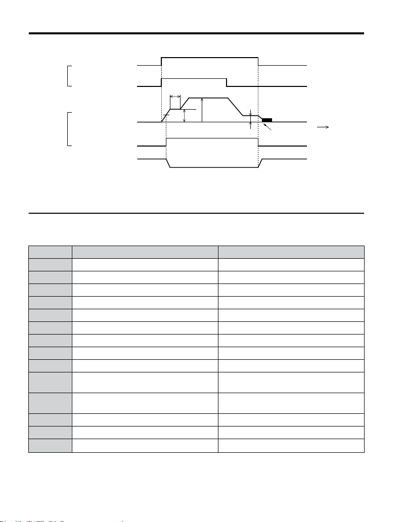
4.5 Application Selection
OFF
S1-SC
S6-SC
P2-PC
UP
Fast/Slow
Output frequency
0
Frequency Detection 2
(H2-03=05)
Holding brake
Figure 4.7 Holding Brake Time Chart
Table 4.15 Preset 7: Parameters and Settings
Input
Output
u
Setting 7: Preset 7
No. Parameter Name Default Setting
A1-02 Control Mode 0: V/f Control
b1-01 Frequency Reference Selection 0: Operator
C1-01 Acceleration Time 1 3.0 s
C1-02 Deceleration Time 1 3.0 s
C6-01 Duty Cycle 0: Heavy Duty
C6-02 Carrier Frequency Selection 2: 5 kHz
d1-01 Frequency Reference 1 6.0 Hz
d1-02 Frequency Reference 2 30.0 Hz
d1-03 Frequency Reference 3 60.0 Hz
H1-05
H1-06
Multi-Function Digital Input Terminal S5
Function
Multi-Function Digital Input Terminal S6
Function
H2-02 Terminals P1 Function Selection 37: During frequency output
L3-04 Stall Prevention Selection during Decel 0: Disabled
L8-05 Input Phase Loss Protection Selection
ON
OFF
ON
b6-02
d1-03
b6-01
L4-01
ON
Open
Closed Closed
d1-01 (Enabled when b1-01 = 0)
OFF
3: Multi-Step Speed 1
4: Multi-Step Speed 2
1: Enabled
<1>
b2-01
DC Injection braking
Time
100
YASKAWA ELECTRIC TOEP C710606 14E YASKAWA AC Drive – V1000 Quick Start Guide
 Loading...