

Page 1

YASKAWA AC Drive A1000
High Performance Vector Control Drive
Technical Manual
Type: CIMR-AA , CIMR-AT
Models:
To properly use the product, read this manual thoroughly and retain
for easy reference, inspection, and maintenance. Ensure the end user
receives this manual.
200 V Class: 0.4 to 55 kW
400 V Class: 0.4 to 90 kW
Receiving
Mechanical Installation
Electrical Installation
Start-Up Programming &
Operation
Parameter Details
Troubleshooting
Periodic Inspection &
Maintenance
Peripheral Devices &
Options
Specifications
Parameter List
MEMOBUS/Modbus
Communications
1
2
3
4
5
6
7
8
A
B
C
MANUAL NO. SIEP C710616 21A
Standards Compliance
Quick Reference Sheet
D
E
Page 2

This Page Intentionally Blank
Page 3

◆ Quick Reference
Easily Set Parameters for Specific Applications
Preset parameter defaults are available for setting up applications. Refer to Application Selection on page 97.
Run a Motor One-Frame Larger
This drive can operate a motor one frame size larger when running variable torque loads such as fans and pumps. Refer to C6-01: Drive Duty Mode Selection on page 168.
Drive a Synchronous PM Motor
A1000 can operate synchronous PM motors. Refer to Subchart A-3: Operation with Permanent Magnet Motors on page 95.
Perform Auto-Tuning
Automatic tuning sets motor parameters. Refer to Auto-Tuning on page 103.
Maintenance Check Using Drive Monitors
Use drive monitors to check the if fans, capacitors, and other components may require maintenance. Refer to Performance Life Monitors Maintenance Monitors on page 337.
Fault Display and Troubleshooting
Refer to Drive Alarms, Faults, and Errors on page 292 and Refer to Troubleshooting without Fault Display on page 324.
Standards Compliance
Refer to European Standards on page 478 and Refer to UL Standards on page 484.
YASKAWA ELECTRIC SIEP C710616 21A YASKAWA AC Drive - A1000 Technical Manual 3
Page 4

4 YASKAWA ELECTRIC SIEP C710616 21A YASKAWA AC Drive - A1000 Technical Manual
Page 5

Table of Contents
Quick Reference . . . . . . . . . . . . . . . . . . . . . . . . . . . . . . . . . . . . . . . . . . . . . . . . . . . . . . 3
TABLE OF CONTENTS.................................................................................................... 5
I. PREFACE & GENERAL SAFETY ....................................................................... 13
i.1 Preface . . . . . . . . . . . . . . . . . . . . . . . . . . . . . . . . . . . . . . . . . . . . . . . . . . . . . . . . . . . . 14
Applicable Documentation . . . . . . . . . . . . . . . . . . . . . . . . . . . . . . . . . . . . . . . . . . . . . 14
Symbols . . . . . . . . . . . . . . . . . . . . . . . . . . . . . . . . . . . . . . . . . . . . . . . . . . . . . . . . . . . 14
Terms and Abbreviations . . . . . . . . . . . . . . . . . . . . . . . . . . . . . . . . . . . . . . . . . . . . . . 14
i.2 General Safety . . . . . . . . . . . . . . . . . . . . . . . . . . . . . . . . . . . . . . . . . . . . . . . . . . . . . . 15
Supplemental Safety Information . . . . . . . . . . . . . . . . . . . . . . . . . . . . . . . . . . . . . . . . 15
Safety Messages . . . . . . . . . . . . . . . . . . . . . . . . . . . . . . . . . . . . . . . . . . . . . . . . . . . . . 16
Application Notes . . . . . . . . . . . . . . . . . . . . . . . . . . . . . . . . . . . . . . . . . . . . . . . . . . . . 17
Notes on Motor Operation . . . . . . . . . . . . . . . . . . . . . . . . . . . . . . . . . . . . . . . . . . . . . . 20
Applications with Specialized Motors . . . . . . . . . . . . . . . . . . . . . . . . . . . . . . . . . . . . . 21
Drive Label Warnings . . . . . . . . . . . . . . . . . . . . . . . . . . . . . . . . . . . . . . . . . . . . . . . . . 22
Warranty Information . . . . . . . . . . . . . . . . . . . . . . . . . . . . . . . . . . . . . . . . . . . . . . . . . . 23
1. RECEIVING .......................................................................................................... 25
1.1 Section Safety . . . . . . . . . . . . . . . . . . . . . . . . . . . . . . . . . . . . . . . . . . . . . . . . . . . . . . 26
1.2 General Description . . . . . . . . . . . . . . . . . . . . . . . . . . . . . . . . . . . . . . . . . . . . . . . . . 27
A1000 Model Selection . . . . . . . . . . . . . . . . . . . . . . . . . . . . . . . . . . . . . . . . . . . . . . . . 27
Control Mode Selection . . . . . . . . . . . . . . . . . . . . . . . . . . . . . . . . . . . . . . . . . . . . . . . . 28
1.3 Model Number and Nameplate Check . . . . . . . . . . . . . . . . . . . . . . . . . . . . . . . . . . 29
Nameplate . . . . . . . . . . . . . . . . . . . . . . . . . . . . . . . . . . . . . . . . . . . . . . . . . . . . . . . . . . 29
1.4 Drive Models and Enclosure Types . . . . . . . . . . . . . . . . . . . . . . . . . . . . . . . . . . . . 31
1.5 Component Names . . . . . . . . . . . . . . . . . . . . . . . . . . . . . . . . . . . . . . . . . . . . . . . . . . 32
IP20/NEMA Type 1 Enclosure . . . . . . . . . . . . . . . . . . . . . . . . . . . . . . . . . . . . . . . . . . 32
IP00/Open-Chassis . . . . . . . . . . . . . . . . . . . . . . . . . . . . . . . . . . . . . . . . . . . . . . . . . . . 33
Front Views . . . . . . . . . . . . . . . . . . . . . . . . . . . . . . . . . . . . . . . . . . . . . . . . . . . . . . . . . 35
2. MECHANICAL INSTALLATION .......................................................................... 37
2.1 Section Safety . . . . . . . . . . . . . . . . . . . . . . . . . . . . . . . . . . . . . . . . . . . . . . . . . . . . . . 38
2.2 Mechanical Installation . . . . . . . . . . . . . . . . . . . . . . . . . . . . . . . . . . . . . . . . . . . . . . 40
Installation Environment . . . . . . . . . . . . . . . . . . . . . . . . . . . . . . . . . . . . . . . . . . . . . . . 40
Installation Orientation and Spacing . . . . . . . . . . . . . . . . . . . . . . . . . . . . . . . . . . . . . . 41
Digital Operator Remote Usage . . . . . . . . . . . . . . . . . . . . . . . . . . . . . . . . . . . . . . . . . 42
Exterior and Mounting Dimensions . . . . . . . . . . . . . . . . . . . . . . . . . . . . . . . . . . . . . . . 45
YASKAWA ELECTRIC SIEP C710616 21A YASKAWA AC Drive - A1000 Technical Manual 5
Page 6

3. ELECTRICAL INSTALLATION ............................................................................ 49
3.1 Section Safety. . . . . . . . . . . . . . . . . . . . . . . . . . . . . . . . . . . . . . . . . . . . . . . . . . . . . . .50
3.2 Standard Connection Diagram . . . . . . . . . . . . . . . . . . . . . . . . . . . . . . . . . . . . . . . . .52
3.3 Main Circuit Connection Diagram. . . . . . . . . . . . . . . . . . . . . . . . . . . . . . . . . . . . . . .55
Three-Phase 200 V Class (CIMR-A2A0004 to 0081)
Three-Phase 400 V Class (CIMR-A4A0002 to 0044) . . . . . . . . . . . . . . . . . . . . . . . .55
Three-Phase 200 V Class (CIMR-A2A0110, 0138)
Three-Phase 400 V Class (CIMR-A4A0058, 0072) . . . . . . . . . . . . . . . . . . . . . . . . . .55
Three-Phase 200 V Class (CIMR-A2A0169, 0211)
Three-Phase 400 V Class (CIMR-A4A0088 to 0165) . . . . . . . . . . . . . . . . . . . . . . . .55
3.4 Terminal Block Configuration. . . . . . . . . . . . . . . . . . . . . . . . . . . . . . . . . . . . . . . . . .56
3.5 Terminal Cover . . . . . . . . . . . . . . . . . . . . . . . . . . . . . . . . . . . . . . . . . . . . . . . . . . . . . .57
CIMR-A2A0004 to 0081, 4A0002 to 0044 (IP20/NEMA Type 1) . . . . . . . . . . . . . . . .57
CIMR-A2A0110 to 0211, 4A0058 to 0165 (IP00/Open-Chassis) . . . . . . . . . . . . . . .58
3.6 Digital Operator and Front Cover . . . . . . . . . . . . . . . . . . . . . . . . . . . . . . . . . . . . . . .59
Removing/Reattaching the Digital Operator . . . . . . . . . . . . . . . . . . . . . . . . . . . . . . . . .59
Removing/Reattaching the Front Cover . . . . . . . . . . . . . . . . . . . . . . . . . . . . . . . . . . . .59
3.7 Protective Cover. . . . . . . . . . . . . . . . . . . . . . . . . . . . . . . . . . . . . . . . . . . . . . . . . . . . .60
Removing the Protective Cover . . . . . . . . . . . . . . . . . . . . . . . . . . . . . . . . . . . . . . . . . .60
Reattaching the Protective Cover . . . . . . . . . . . . . . . . . . . . . . . . . . . . . . . . . . . . . . . . .60
3.8 Main Circuit Wiring. . . . . . . . . . . . . . . . . . . . . . . . . . . . . . . . . . . . . . . . . . . . . . . . . . .61
Main Circuit Terminal Functions . . . . . . . . . . . . . . . . . . . . . . . . . . . . . . . . . . . . . . . . . .61
Wire Gauges and Tightening Torque . . . . . . . . . . . . . . . . . . . . . . . . . . . . . . . . . . . . . .61
Main Circuit Terminal and Motor Wiring . . . . . . . . . . . . . . . . . . . . . . . . . . . . . . . . . . . .64
3.9 Control Circuit Wiring . . . . . . . . . . . . . . . . . . . . . . . . . . . . . . . . . . . . . . . . . . . . . . . .66
Control Circuit Terminal Block Functions . . . . . . . . . . . . . . . . . . . . . . . . . . . . . . . . . . .67
Terminal Configuration . . . . . . . . . . . . . . . . . . . . . . . . . . . . . . . . . . . . . . . . . . . . . . . . .69
Wiring the Control Circuit Terminal . . . . . . . . . . . . . . . . . . . . . . . . . . . . . . . . . . . . . . . .70
3.10 Control I/O Connections . . . . . . . . . . . . . . . . . . . . . . . . . . . . . . . . . . . . . . . . . . . . .72
Sinking/Sourcing Mode Switch for Digital Inputs . . . . . . . . . . . . . . . . . . . . . . . . . . . . .72
Using the Photocoupler and Contact Outputs . . . . . . . . . . . . . . . . . . . . . . . . . . . . . . .74
Using the Pulse Train Output . . . . . . . . . . . . . . . . . . . . . . . . . . . . . . . . . . . . . . . . . . . .74
3.11 Terminal A2 Analog Input Signal Selection. . . . . . . . . . . . . . . . . . . . . . . . . . . . . .75
Terminal A2 Input Signal Selection . . . . . . . . . . . . . . . . . . . . . . . . . . . . . . . . . . . . . . .75
3.12 Connect to a PC . . . . . . . . . . . . . . . . . . . . . . . . . . . . . . . . . . . . . . . . . . . . . . . . . . . .76
3.13 MEMOBUS/Modbus Termination . . . . . . . . . . . . . . . . . . . . . . . . . . . . . . . . . . . . . .77
3.14 External Interlock . . . . . . . . . . . . . . . . . . . . . . . . . . . . . . . . . . . . . . . . . . . . . . . . . . .78
Drive Ready . . . . . . . . . . . . . . . . . . . . . . . . . . . . . . . . . . . . . . . . . . . . . . . . . . . . . . . . .78
3.15 Wiring Checklist . . . . . . . . . . . . . . . . . . . . . . . . . . . . . . . . . . . . . . . . . . . . . . . . . . . .79
4. START-UP PROGRAMMING & OPERATION .................................................... 81
4.1 Section Safety. . . . . . . . . . . . . . . . . . . . . . . . . . . . . . . . . . . . . . . . . . . . . . . . . . . . . . .82
4.2 Using the Digital Operator. . . . . . . . . . . . . . . . . . . . . . . . . . . . . . . . . . . . . . . . . . . . .83
Keys and Displays . . . . . . . . . . . . . . . . . . . . . . . . . . . . . . . . . . . . . . . . . . . . . . . . . . . .83
Digital Text Display . . . . . . . . . . . . . . . . . . . . . . . . . . . . . . . . . . . . . . . . . . . . . . . . . . . .84
LED Screen Displays . . . . . . . . . . . . . . . . . . . . . . . . . . . . . . . . . . . . . . . . . . . . . . . . . .84
LO/RE LED and RUN LED Indications . . . . . . . . . . . . . . . . . . . . . . . . . . . . . . . . . . . . .85
Menu Structure for Digital Operator . . . . . . . . . . . . . . . . . . . . . . . . . . . . . . . . . . . . . . .86
4.3 The Drive and Programming Modes. . . . . . . . . . . . . . . . . . . . . . . . . . . . . . . . . . . . .87
Navigating the Drive and Programming Modes . . . . . . . . . . . . . . . . . . . . . . . . . . . . . .87
Changing Parameter Settings or Values . . . . . . . . . . . . . . . . . . . . . . . . . . . . . . . . . . .89
Verifying Parameter Changes: Verify Menu . . . . . . . . . . . . . . . . . . . . . . . . . . . . . . . . .89
Simplified Setup Using the Setup Group . . . . . . . . . . . . . . . . . . . . . . . . . . . . . . . . . . .90
Switching Between LOCAL and REMOTE . . . . . . . . . . . . . . . . . . . . . . . . . . . . . . . . . .91
6 YASKAWA ELECTRIC SIEP C710616 21A YASKAWA AC Drive - A1000 Technical Manual
Page 7

4.4 Start-Up Flowcharts . . . . . . . . . . . . . . . . . . . . . . . . . . . . . . . . . . . . . . . . . . . . . . . . . 92
Flowchart A: Basic Start-up and Motor Tuning . . . . . . . . . . . . . . . . . . . . . . . . . . . . . . 92
Subchart A-1: Simple Motor Setup Using V/f Control . . . . . . . . . . . . . . . . . . . . . . . . . 93
Subchart A-2: High Performance Operation Using OLV or CLV . . . . . . . . . . . . . . . . . 94
Subchart A-3: Operation with Permanent Magnet Motors . . . . . . . . . . . . . . . . . . . . . . 95
4.5 Powering Up the Drive . . . . . . . . . . . . . . . . . . . . . . . . . . . . . . . . . . . . . . . . . . . . . . . 96
Powering Up the Drive and Operation Status Display . . . . . . . . . . . . . . . . . . . . . . . . . 96
4.6 Application Selection . . . . . . . . . . . . . . . . . . . . . . . . . . . . . . . . . . . . . . . . . . . . . . . . 97
Setting 1: Water Supply Pump Application . . . . . . . . . . . . . . . . . . . . . . . . . . . . . . . . . 97
Setting 2: Conveyor Application . . . . . . . . . . . . . . . . . . . . . . . . . . . . . . . . . . . . . . . . . . 97
Setting 3: Exhaust Fan Application . . . . . . . . . . . . . . . . . . . . . . . . . . . . . . . . . . . . . . . 98
Setting 4: HVAC Fan Application . . . . . . . . . . . . . . . . . . . . . . . . . . . . . . . . . . . . . . . . . 98
Setting 5: Compressor Application . . . . . . . . . . . . . . . . . . . . . . . . . . . . . . . . . . . . . . . 99
Setting 6: Hoist Application . . . . . . . . . . . . . . . . . . . . . . . . . . . . . . . . . . . . . . . . . . . . . 99
Notes on Controlling the Brake when Using the Hoist Application Preset . . . . . . . . . 100
Setting 7: Traveling Application . . . . . . . . . . . . . . . . . . . . . . . . . . . . . . . . . . . . . . . . . 101
4.7 Auto-Tuning . . . . . . . . . . . . . . . . . . . . . . . . . . . . . . . . . . . . . . . . . . . . . . . . . . . . . . . 103
Types of Auto-Tuning . . . . . . . . . . . . . . . . . . . . . . . . . . . . . . . . . . . . . . . . . . . . . . . . 103
Before Auto-Tuning the Drive . . . . . . . . . . . . . . . . . . . . . . . . . . . . . . . . . . . . . . . . . . 105
Auto-Tuning Interruption and Fault Codes . . . . . . . . . . . . . . . . . . . . . . . . . . . . . . . . . 106
Auto-Tuning Operation Example . . . . . . . . . . . . . . . . . . . . . . . . . . . . . . . . . . . . . . . . 106
Parameter Settings during Induction Motor Auto-Tuning: T1 . . . . . . . . . . . . . . . . . . . 108
Parameter Settings during PM Motor Auto-Tuning: T2 . . . . . . . . . . . . . . . . . . . . . . . 110
Parameter Settings during Inertia and Speed Control Loop Auto-Tuning: T3 . . . . . . 112
4.8 No-Load Operation Test Run . . . . . . . . . . . . . . . . . . . . . . . . . . . . . . . . . . . . . . . . . 114
No-Load Operation Test Run . . . . . . . . . . . . . . . . . . . . . . . . . . . . . . . . . . . . . . . . . . . 114
4.9 Test Run with Load Connected . . . . . . . . . . . . . . . . . . . . . . . . . . . . . . . . . . . . . . . 115
Test Run with the Load Connected . . . . . . . . . . . . . . . . . . . . . . . . . . . . . . . . . . . . . . 115
4.10 Verifying Parameter Settings and Backing Up Changes. . . . . . . . . . . . . . . . . . 116
Backing Up Parameter Values: o2-03 . . . . . . . . . . . . . . . . . . . . . . . . . . . . . . . . . . . . 116
Parameter Access Level: A1-01 . . . . . . . . . . . . . . . . . . . . . . . . . . . . . . . . . . . . . . . . 116
Password Settings: A1-04, A1-05 . . . . . . . . . . . . . . . . . . . . . . . . . . . . . . . . . . . . . . . 116
Copy Function . . . . . . . . . . . . . . . . . . . . . . . . . . . . . . . . . . . . . . . . . . . . . . . . . . . . . . 117
4.11 Test Run Checklist . . . . . . . . . . . . . . . . . . . . . . . . . . . . . . . . . . . . . . . . . . . . . . . . 118
5. PARAMETER DETAILS..................................................................................... 121
5.1 A: Initialization. . . . . . . . . . . . . . . . . . . . . . . . . . . . . . . . . . . . . . . . . . . . . . . . . . . . . 122
A1: Initialization . . . . . . . . . . . . . . . . . . . . . . . . . . . . . . . . . . . . . . . . . . . . . . . . . . . . . 122
A2: User Parameters . . . . . . . . . . . . . . . . . . . . . . . . . . . . . . . . . . . . . . . . . . . . . . . . . 126
5.2 b: Application. . . . . . . . . . . . . . . . . . . . . . . . . . . . . . . . . . . . . . . . . . . . . . . . . . . . . . 127
b1: Operation Mode Selection . . . . . . . . . . . . . . . . . . . . . . . . . . . . . . . . . . . . . . . . . . 127
b2: DC Injection Braking and Short Circuit Braking . . . . . . . . . . . . . . . . . . . . . . . . . . 134
b3: Speed Search . . . . . . . . . . . . . . . . . . . . . . . . . . . . . . . . . . . . . . . . . . . . . . . . . . . 137
b4: Delay Timers . . . . . . . . . . . . . . . . . . . . . . . . . . . . . . . . . . . . . . . . . . . . . . . . . . . . 142
b5: PID Control . . . . . . . . . . . . . . . . . . . . . . . . . . . . . . . . . . . . . . . . . . . . . . . . . . . . . 142
b6: Dwell Function . . . . . . . . . . . . . . . . . . . . . . . . . . . . . . . . . . . . . . . . . . . . . . . . . . . 152
b7: Droop Control (CLV, CLV/PM) . . . . . . . . . . . . . . . . . . . . . . . . . . . . . . . . . . . . . . . 153
b8: Energy Saving . . . . . . . . . . . . . . . . . . . . . . . . . . . . . . . . . . . . . . . . . . . . . . . . . . . 154
b9: Zero Servo . . . . . . . . . . . . . . . . . . . . . . . . . . . . . . . . . . . . . . . . . . . . . . . . . . . . . . 155
5.3 C: Tuning . . . . . . . . . . . . . . . . . . . . . . . . . . . . . . . . . . . . . . . . . . . . . . . . . . . . . . . . . 156
C1: Acceleration and Deceleration Times . . . . . . . . . . . . . . . . . . . . . . . . . . . . . . . . . 156
C2: S-Curve Characteristics . . . . . . . . . . . . . . . . . . . . . . . . . . . . . . . . . . . . . . . . . . . 158
C3: Slip Compensation . . . . . . . . . . . . . . . . . . . . . . . . . . . . . . . . . . . . . . . . . . . . . . . 158
C4: Torque Compensation . . . . . . . . . . . . . . . . . . . . . . . . . . . . . . . . . . . . . . . . . . . . . 161
C5: Automatic Speed Regulator (ASR) . . . . . . . . . . . . . . . . . . . . . . . . . . . . . . . . . . . 162
YASKAWA ELECTRIC SIEP C710616 21A YASKAWA AC Drive - A1000 Technical Manual 7
Page 8

C6: Carrier Frequency . . . . . . . . . . . . . . . . . . . . . . . . . . . . . . . . . . . . . . . . . . . . . . . .168
5.4 d: Reference Settings . . . . . . . . . . . . . . . . . . . . . . . . . . . . . . . . . . . . . . . . . . . . . . .171
d1: Frequency Reference . . . . . . . . . . . . . . . . . . . . . . . . . . . . . . . . . . . . . . . . . . . . . .171
d2: Frequency Upper/Lower Limits . . . . . . . . . . . . . . . . . . . . . . . . . . . . . . . . . . . . . . .172
d3: Jump Frequency . . . . . . . . . . . . . . . . . . . . . . . . . . . . . . . . . . . . . . . . . . . . . . . . . .173
d4: Frequency Reference Hold and Up/Down 2 Function . . . . . . . . . . . . . . . . . . . . .174
d5: Torque Control . . . . . . . . . . . . . . . . . . . . . . . . . . . . . . . . . . . . . . . . . . . . . . . . . . .178
d6: Field Weakening and Field Forcing . . . . . . . . . . . . . . . . . . . . . . . . . . . . . . . . . . .182
d7: Offset Frequency . . . . . . . . . . . . . . . . . . . . . . . . . . . . . . . . . . . . . . . . . . . . . . . . .183
5.5 E: Motor Parameters . . . . . . . . . . . . . . . . . . . . . . . . . . . . . . . . . . . . . . . . . . . . . . . .184
E1: V/f Pattern for Motor 1 . . . . . . . . . . . . . . . . . . . . . . . . . . . . . . . . . . . . . . . . . . . . .184
E2: Motor 1 Parameters . . . . . . . . . . . . . . . . . . . . . . . . . . . . . . . . . . . . . . . . . . . . . . .188
E3: V/f Pattern for Motor 2 . . . . . . . . . . . . . . . . . . . . . . . . . . . . . . . . . . . . . . . . . . . . .191
E4: Motor 2 Parameters . . . . . . . . . . . . . . . . . . . . . . . . . . . . . . . . . . . . . . . . . . . . . . .192
E5: PM Motor Settings . . . . . . . . . . . . . . . . . . . . . . . . . . . . . . . . . . . . . . . . . . . . . . . .194
5.6 F: Option Settings . . . . . . . . . . . . . . . . . . . . . . . . . . . . . . . . . . . . . . . . . . . . . . . . . .197
F1: PG Speed Control Card Settings . . . . . . . . . . . . . . . . . . . . . . . . . . . . . . . . . . . . .197
F2: Analog Input Card Settings . . . . . . . . . . . . . . . . . . . . . . . . . . . . . . . . . . . . . . . . .200
F3: Digital Input Card Settings . . . . . . . . . . . . . . . . . . . . . . . . . . . . . . . . . . . . . . . . . .200
F4: Analog Monitor Card Settings . . . . . . . . . . . . . . . . . . . . . . . . . . . . . . . . . . . . . . .201
F5: Digital Output Card Settings . . . . . . . . . . . . . . . . . . . . . . . . . . . . . . . . . . . . . . . . .202
F6: Communication Option Card . . . . . . . . . . . . . . . . . . . . . . . . . . . . . . . . . . . . . . . .202
CC-Link Parameters . . . . . . . . . . . . . . . . . . . . . . . . . . . . . . . . . . . . . . . . . . . . . . . . . .203
PROFIBUS-DP Parameters . . . . . . . . . . . . . . . . . . . . . . . . . . . . . . . . . . . . . . . . . . . .204
CANopen Parameters . . . . . . . . . . . . . . . . . . . . . . . . . . . . . . . . . . . . . . . . . . . . . . . .205
DeviceNet Parameters . . . . . . . . . . . . . . . . . . . . . . . . . . . . . . . . . . . . . . . . . . . . . . . .205
5.7 H: Terminal Functions . . . . . . . . . . . . . . . . . . . . . . . . . . . . . . . . . . . . . . . . . . . . . . .207
H1: Multi-Function Digital Inputs . . . . . . . . . . . . . . . . . . . . . . . . . . . . . . . . . . . . . . . . .207
H2: Multi-Function Digital Outputs . . . . . . . . . . . . . . . . . . . . . . . . . . . . . . . . . . . . . . .217
H3: Multi-Function Analog Inputs . . . . . . . . . . . . . . . . . . . . . . . . . . . . . . . . . . . . . . . .226
H4: Multi-Function Analog Outputs . . . . . . . . . . . . . . . . . . . . . . . . . . . . . . . . . . . . . . .232
H5: MEMOBUS/Modbus Serial Communication . . . . . . . . . . . . . . . . . . . . . . . . . . . .233
H6: Pulse Train Input/Output . . . . . . . . . . . . . . . . . . . . . . . . . . . . . . . . . . . . . . . . . . .233
5.8 L: Protection Functions. . . . . . . . . . . . . . . . . . . . . . . . . . . . . . . . . . . . . . . . . . . . . .236
L1: Motor Protection . . . . . . . . . . . . . . . . . . . . . . . . . . . . . . . . . . . . . . . . . . . . . . . . . .236
L2: Momentary Power Loss Ride-Thru . . . . . . . . . . . . . . . . . . . . . . . . . . . . . . . . . . . .241
L3: Stall Prevention . . . . . . . . . . . . . . . . . . . . . . . . . . . . . . . . . . . . . . . . . . . . . . . . . .247
L4: Speed Detection . . . . . . . . . . . . . . . . . . . . . . . . . . . . . . . . . . . . . . . . . . . . . . . . . .254
L5: Fault Restart . . . . . . . . . . . . . . . . . . . . . . . . . . . . . . . . . . . . . . . . . . . . . . . . . . . . .255
L6: Torque Detection . . . . . . . . . . . . . . . . . . . . . . . . . . . . . . . . . . . . . . . . . . . . . . . . .256
L7: Torque Limit . . . . . . . . . . . . . . . . . . . . . . . . . . . . . . . . . . . . . . . . . . . . . . . . . . . . .259
L8: Drive Protection . . . . . . . . . . . . . . . . . . . . . . . . . . . . . . . . . . . . . . . . . . . . . . . . . .260
5.9 n: Special Adjustments . . . . . . . . . . . . . . . . . . . . . . . . . . . . . . . . . . . . . . . . . . . . . .266
n1: Hunting Prevention . . . . . . . . . . . . . . . . . . . . . . . . . . . . . . . . . . . . . . . . . . . . . . . .266
n2: Speed Feedback Detection Contol (AFR) Tuning . . . . . . . . . . . . . . . . . . . . . . . .266
n3: High Slip Braking (HSB) and Overexcitation Braking . . . . . . . . . . . . . . . . . . . . . .267
n5: Feed Forward Control . . . . . . . . . . . . . . . . . . . . . . . . . . . . . . . . . . . . . . . . . . . . . .269
n6: Online Tuning . . . . . . . . . . . . . . . . . . . . . . . . . . . . . . . . . . . . . . . . . . . . . . . . . . . .271
n8: PM Motor Control Tuning . . . . . . . . . . . . . . . . . . . . . . . . . . . . . . . . . . . . . . . . . . .272
5.10 o: Operator Related Settings. . . . . . . . . . . . . . . . . . . . . . . . . . . . . . . . . . . . . . . . .275
o1: Digital Operator Display Selection . . . . . . . . . . . . . . . . . . . . . . . . . . . . . . . . . . . .275
o2: Digital Operator Keypad Functions . . . . . . . . . . . . . . . . . . . . . . . . . . . . . . . . . . . .276
o3: Copy Function . . . . . . . . . . . . . . . . . . . . . . . . . . . . . . . . . . . . . . . . . . . . . . . . . . .278
o4: Maintenance Monitor Settings . . . . . . . . . . . . . . . . . . . . . . . . . . . . . . . . . . . . . . .279
q: DriveWorksEZ Parameters . . . . . . . . . . . . . . . . . . . . . . . . . . . . . . . . . . . . . . . . . . .280
8 YASKAWA ELECTRIC SIEP C710616 21A YASKAWA AC Drive - A1000 Technical Manual
Page 9

r: DriveWorksEZ Connection Parameters . . . . . . . . . . . . . . . . . . . . . . . . . . . . . . . . . 280
T: Motor Tuning . . . . . . . . . . . . . . . . . . . . . . . . . . . . . . . . . . . . . . . . . . . . . . . . . . . . . 281
5.11 U: Monitor Parameters . . . . . . . . . . . . . . . . . . . . . . . . . . . . . . . . . . . . . . . . . . . . . 282
U1: Operation Status Monitors . . . . . . . . . . . . . . . . . . . . . . . . . . . . . . . . . . . . . . . . . 282
U2: Fault Trace . . . . . . . . . . . . . . . . . . . . . . . . . . . . . . . . . . . . . . . . . . . . . . . . . . . . . 282
U3: Fault History . . . . . . . . . . . . . . . . . . . . . . . . . . . . . . . . . . . . . . . . . . . . . . . . . . . . 282
U4: Maintenance Monitors . . . . . . . . . . . . . . . . . . . . . . . . . . . . . . . . . . . . . . . . . . . . . 282
U5: PID Monitors . . . . . . . . . . . . . . . . . . . . . . . . . . . . . . . . . . . . . . . . . . . . . . . . . . . . 282
U6: Operation Status Monitors . . . . . . . . . . . . . . . . . . . . . . . . . . . . . . . . . . . . . . . . . 282
U8: DriveWorksEZ Monitors . . . . . . . . . . . . . . . . . . . . . . . . . . . . . . . . . . . . . . . . . . . 283
6. TROUBLESHOOTING ....................................................................................... 285
6.1 Section Safety . . . . . . . . . . . . . . . . . . . . . . . . . . . . . . . . . . . . . . . . . . . . . . . . . . . . . 286
6.2 Motor Performance Fine-Tuning . . . . . . . . . . . . . . . . . . . . . . . . . . . . . . . . . . . . . . 288
Fine-Tuning V/f Control and V/f Control with PG . . . . . . . . . . . . . . . . . . . . . . . . . . . . 288
Fine-Tuning Open Loop Vector Control . . . . . . . . . . . . . . . . . . . . . . . . . . . . . . . . . . . 288
Fine-Tuning Closed Loop Vector Control . . . . . . . . . . . . . . . . . . . . . . . . . . . . . . . . . 289
Fine-Tuning Open Loop Vector Control for PM Motors . . . . . . . . . . . . . . . . . . . . . . . 289
Fine-Tuning Advanced Open Loop Vector Control for PM Motors . . . . . . . . . . . . . . 290
Fine-Tuning Closed Loop Vector Control for PM Motors . . . . . . . . . . . . . . . . . . . . . . 290
Parameters to Minimize Motor Hunting and Oscillation . . . . . . . . . . . . . . . . . . . . . . . 291
6.3 Drive Alarms, Faults, and Errors . . . . . . . . . . . . . . . . . . . . . . . . . . . . . . . . . . . . . . 292
Types of Alarms, Faults, and Errors . . . . . . . . . . . . . . . . . . . . . . . . . . . . . . . . . . . . . 292
Alarm and Error Displays . . . . . . . . . . . . . . . . . . . . . . . . . . . . . . . . . . . . . . . . . . . . . . 293
6.4 Fault Detection. . . . . . . . . . . . . . . . . . . . . . . . . . . . . . . . . . . . . . . . . . . . . . . . . . . . . 297
Fault Displays, Causes, and Possible Solutions . . . . . . . . . . . . . . . . . . . . . . . . . . . . 297
6.5 Alarm Detection. . . . . . . . . . . . . . . . . . . . . . . . . . . . . . . . . . . . . . . . . . . . . . . . . . . . 308
Alarm Codes, Causes, and Possible Solutions . . . . . . . . . . . . . . . . . . . . . . . . . . . . . 308
6.6 Operator Programming Errors . . . . . . . . . . . . . . . . . . . . . . . . . . . . . . . . . . . . . . . . 314
oPE Codes, Causes, and Possible Solutions . . . . . . . . . . . . . . . . . . . . . . . . . . . . . . 314
6.7 Auto-Tuning Fault Detection . . . . . . . . . . . . . . . . . . . . . . . . . . . . . . . . . . . . . . . . . 317
Auto-Tuning Codes, Causes, and Possible Solutions . . . . . . . . . . . . . . . . . . . . . . . . 317
6.8 Copy Function Related Displays . . . . . . . . . . . . . . . . . . . . . . . . . . . . . . . . . . . . . . 320
Tasks, Errors, and Troubleshooting . . . . . . . . . . . . . . . . . . . . . . . . . . . . . . . . . . . . . . 320
6.9 Diagnosing and Resetting Faults. . . . . . . . . . . . . . . . . . . . . . . . . . . . . . . . . . . . . . 322
Fault Occurs Simultaneously with Power Loss . . . . . . . . . . . . . . . . . . . . . . . . . . . . . 322
If the Drive Still has Power After a Fault Occurs . . . . . . . . . . . . . . . . . . . . . . . . . . . . 322
Viewing Fault Trace Data After Fault . . . . . . . . . . . . . . . . . . . . . . . . . . . . . . . . . . . . . 322
Fault Reset Methods . . . . . . . . . . . . . . . . . . . . . . . . . . . . . . . . . . . . . . . . . . . . . . . . . 323
6.10 Troubleshooting without Fault Display. . . . . . . . . . . . . . . . . . . . . . . . . . . . . . . . 324
Common Problems . . . . . . . . . . . . . . . . . . . . . . . . . . . . . . . . . . . . . . . . . . . . . . . . . . 324
Cannot Change Parameter Settings . . . . . . . . . . . . . . . . . . . . . . . . . . . . . . . . . . . . . 324
Motor Does Not Rotate Properly after Pressing RUN Button or after Entering
External Run Command . . . . . . . . . . . . . . . . . . . . . . . . . . . . . . . . . . . . . . . . . . . . . . 325
Motor is Too Hot . . . . . . . . . . . . . . . . . . . . . . . . . . . . . . . . . . . . . . . . . . . . . . . . . . . . 326
Drive Does Not Allow Selection the Desired Auto-Tuning Mode . . . . . . . . . . . . . . . . 326
oPE02 Error Occurs When Lowering the Motor Rated Current Setting . . . . . . . . . . . 326
Motor Stalls during Acceleration or Acceleration Time is Too Long . . . . . . . . . . . . . 326
Drive Frequency Reference Differs from the Controller Frequency Reference
Command . . . . . . . . . . . . . . . . . . . . . . . . . . . . . . . . . . . . . . . . . . . . . . . . . . . . . . . . . 327
Excessive Motor Oscillation and Erratic Rotation . . . . . . . . . . . . . . . . . . . . . . . . . . . 327
Deceleration Takes Longer Than Expected with Dynamic Braking Enabled . . . . . . . 327
Load Falls When Brake is Applied (Hoist-Type Applications) . . . . . . . . . . . . . . . . . . 327
Noise From Drive or Output Lines When the Drive is Powered On . . . . . . . . . . . . . . 328
Ground Fault Circuit Interrupter (GFCI) Trips During Run . . . . . . . . . . . . . . . . . . . . . 328
YASKAWA ELECTRIC SIEP C710616 21A YASKAWA AC Drive - A1000 Technical Manual 9
Page 10

Connected Machinery Vibrates When Motor Rotates . . . . . . . . . . . . . . . . . . . . . . . .328
PID Output Fault . . . . . . . . . . . . . . . . . . . . . . . . . . . . . . . . . . . . . . . . . . . . . . . . . . . . .328
Insufficient Starting Torque . . . . . . . . . . . . . . . . . . . . . . . . . . . . . . . . . . . . . . . . . . . . .328
Motor Rotates After the Drive Output is Shut Off (Motor Rotates During DC Injection
Braking) . . . . . . . . . . . . . . . . . . . . . . . . . . . . . . . . . . . . . . . . . . . . . . . . . . . . . . . . . . .329
Output Frequency is not as High as Frequency Reference . . . . . . . . . . . . . . . . . . . .329
Buzzing Sound from Motor at 2 kHz . . . . . . . . . . . . . . . . . . . . . . . . . . . . . . . . . . . . . .329
Unstable Motor Speed when Using PM . . . . . . . . . . . . . . . . . . . . . . . . . . . . . . . . . . .329
Motor Does Not Restart after Power Loss . . . . . . . . . . . . . . . . . . . . . . . . . . . . . . . . .329
7. PERIODIC INSPECTION & MAINTENANCE .................................................... 331
7.1 Section Safety. . . . . . . . . . . . . . . . . . . . . . . . . . . . . . . . . . . . . . . . . . . . . . . . . . . . . .332
7.2 Inspection . . . . . . . . . . . . . . . . . . . . . . . . . . . . . . . . . . . . . . . . . . . . . . . . . . . . . . . . .335
Recommended Daily Inspection . . . . . . . . . . . . . . . . . . . . . . . . . . . . . . . . . . . . . . . . .335
Recommended Periodic Inspection . . . . . . . . . . . . . . . . . . . . . . . . . . . . . . . . . . . . . .336
7.3 Periodic Maintenance . . . . . . . . . . . . . . . . . . . . . . . . . . . . . . . . . . . . . . . . . . . . . . .337
Replacement Parts . . . . . . . . . . . . . . . . . . . . . . . . . . . . . . . . . . . . . . . . . . . . . . . . . . .337
7.4 Drive Cooling Fans. . . . . . . . . . . . . . . . . . . . . . . . . . . . . . . . . . . . . . . . . . . . . . . . . .339
Number of Cooling Fans and Types . . . . . . . . . . . . . . . . . . . . . . . . . . . . . . . . . . . . . .339
Cooling Fan Replacement . . . . . . . . . . . . . . . . . . . . . . . . . . . . . . . . . . . . . . . . . . . . .339
7.5 Drive Replacement. . . . . . . . . . . . . . . . . . . . . . . . . . . . . . . . . . . . . . . . . . . . . . . . . .344
Serviceable Parts . . . . . . . . . . . . . . . . . . . . . . . . . . . . . . . . . . . . . . . . . . . . . . . . . . . .344
Terminal Board . . . . . . . . . . . . . . . . . . . . . . . . . . . . . . . . . . . . . . . . . . . . . . . . . . . . . .344
Replacing the Drive . . . . . . . . . . . . . . . . . . . . . . . . . . . . . . . . . . . . . . . . . . . . . . . . . .344
8. PERIPHERAL DEVICES & OPTIONS .............................................................. 347
8.1 Section Safety. . . . . . . . . . . . . . . . . . . . . . . . . . . . . . . . . . . . . . . . . . . . . . . . . . . . . .348
8.2 Drive Options and Peripheral Devices . . . . . . . . . . . . . . . . . . . . . . . . . . . . . . . . . .349
8.3 Connecting Peripheral Devices . . . . . . . . . . . . . . . . . . . . . . . . . . . . . . . . . . . . . . .351
8.4 Option Card Installation. . . . . . . . . . . . . . . . . . . . . . . . . . . . . . . . . . . . . . . . . . . . . .352
Installing Option Cards . . . . . . . . . . . . . . . . . . . . . . . . . . . . . . . . . . . . . . . . . . . . . . . .352
Installation Procedure . . . . . . . . . . . . . . . . . . . . . . . . . . . . . . . . . . . . . . . . . . . . . . . . .352
8.5 Installing Peripheral Devices . . . . . . . . . . . . . . . . . . . . . . . . . . . . . . . . . . . . . . . . .354
Braking Options . . . . . . . . . . . . . . . . . . . . . . . . . . . . . . . . . . . . . . . . . . . . . . . . . . . . .354
Installing a Molded Case Circuit Breaker (MCCB) . . . . . . . . . . . . . . . . . . . . . . . . . . .356
Installing a Leakage Breaker . . . . . . . . . . . . . . . . . . . . . . . . . . . . . . . . . . . . . . . . . . .357
Installing a Magnetic Contactor . . . . . . . . . . . . . . . . . . . . . . . . . . . . . . . . . . . . . . . . .357
Connecting an AC or DC Reactor . . . . . . . . . . . . . . . . . . . . . . . . . . . . . . . . . . . . . . .357
Connecting a Surge Absorber . . . . . . . . . . . . . . . . . . . . . . . . . . . . . . . . . . . . . . . . . .358
Connecting a Noise Filter . . . . . . . . . . . . . . . . . . . . . . . . . . . . . . . . . . . . . . . . . . . . . .358
Fuse/Fuse Holder . . . . . . . . . . . . . . . . . . . . . . . . . . . . . . . . . . . . . . . . . . . . . . . . . . . .360
Attachment for External Heatsink . . . . . . . . . . . . . . . . . . . . . . . . . . . . . . . . . . . . . . . .361
EMC Filter Installation . . . . . . . . . . . . . . . . . . . . . . . . . . . . . . . . . . . . . . . . . . . . . . . .361
Installing a Motor Thermal Overload (oL) Relay on the Drive Output . . . . . . . . . . . . .361
A. SPECIFICATIONS .............................................................................................. 363
A.1 Heavy Duty and Normal Duty Ratings . . . . . . . . . . . . . . . . . . . . . . . . . . . . . . . . . .364
A.2 Three-Phase 200 V Class Drives . . . . . . . . . . . . . . . . . . . . . . . . . . . . . . . . . . . . . .365
A.3 Three-Phase 400 V Class Drives . . . . . . . . . . . . . . . . . . . . . . . . . . . . . . . . . . . . . .366
A.4 Drive Specifications . . . . . . . . . . . . . . . . . . . . . . . . . . . . . . . . . . . . . . . . . . . . . . . .367
A.5 Drive Watt Loss Data. . . . . . . . . . . . . . . . . . . . . . . . . . . . . . . . . . . . . . . . . . . . . . . .369
A.6 Drive Derating Data . . . . . . . . . . . . . . . . . . . . . . . . . . . . . . . . . . . . . . . . . . . . . . . . .370
Carrier Frequency Derating . . . . . . . . . . . . . . . . . . . . . . . . . . . . . . . . . . . . . . . . . . . .370
Temperature Derating . . . . . . . . . . . . . . . . . . . . . . . . . . . . . . . . . . . . . . . . . . . . . . . .371
10 YASKAWA ELECTRIC SIEP C710616 21A YASKAWA AC Drive - A1000 Technical Manual
Page 11

B. PARAMETER LIST ............................................................................................ 373
B.1 Understanding the Parameter Table . . . . . . . . . . . . . . . . . . . . . . . . . . . . . . . . . . . 374
Control Modes, Symbols, and Terms . . . . . . . . . . . . . . . . . . . . . . . . . . . . . . . . . . . . . 374
B.2 Parameter Groups. . . . . . . . . . . . . . . . . . . . . . . . . . . . . . . . . . . . . . . . . . . . . . . . . . 375
B.3 Parameter Table . . . . . . . . . . . . . . . . . . . . . . . . . . . . . . . . . . . . . . . . . . . . . . . . . . . 376
A: Initialization Parameters . . . . . . . . . . . . . . . . . . . . . . . . . . . . . . . . . . . . . . . . . . . . 376
b: Application . . . . . . . . . . . . . . . . . . . . . . . . . . . . . . . . . . . . . . . . . . . . . . . . . . . . . . . 377
C: Tuning . . . . . . . . . . . . . . . . . . . . . . . . . . . . . . . . . . . . . . . . . . . . . . . . . . . . . . . . . . 382
d: References . . . . . . . . . . . . . . . . . . . . . . . . . . . . . . . . . . . . . . . . . . . . . . . . . . . . . . 386
E: Motor Parameters . . . . . . . . . . . . . . . . . . . . . . . . . . . . . . . . . . . . . . . . . . . . . . . . . 389
F: Options . . . . . . . . . . . . . . . . . . . . . . . . . . . . . . . . . . . . . . . . . . . . . . . . . . . . . . . . . 393
H Parameters: Multi-Function Terminals . . . . . . . . . . . . . . . . . . . . . . . . . . . . . . . . . . 398
L: Protection Function . . . . . . . . . . . . . . . . . . . . . . . . . . . . . . . . . . . . . . . . . . . . . . . . 409
n: Advanced Performance Set-Up . . . . . . . . . . . . . . . . . . . . . . . . . . . . . . . . . . . . . . . 414
o: Operator Related Parameters . . . . . . . . . . . . . . . . . . . . . . . . . . . . . . . . . . . . . . . . 417
q: DWEZ Parameters . . . . . . . . . . . . . . . . . . . . . . . . . . . . . . . . . . . . . . . . . . . . . . . . . 419
r: DWEZ Connection Parameters . . . . . . . . . . . . . . . . . . . . . . . . . . . . . . . . . . . . . . . 419
T: Motor Tuning . . . . . . . . . . . . . . . . . . . . . . . . . . . . . . . . . . . . . . . . . . . . . . . . . . . . . 419
U: Monitors . . . . . . . . . . . . . . . . . . . . . . . . . . . . . . . . . . . . . . . . . . . . . . . . . . . . . . . . 422
B.4 Control Mode Dependent Parameter Default Values. . . . . . . . . . . . . . . . . . . . . . 429
A1-02 (Motor 1 Control Mode) Dependent Parameters . . . . . . . . . . . . . . . . . . . . . . . 429
E3-01 (Motor 2 Control Mode) Dependent Parameters . . . . . . . . . . . . . . . . . . . . . . . 430
B.5 V/f Pattern Default Values . . . . . . . . . . . . . . . . . . . . . . . . . . . . . . . . . . . . . . . . . . . 431
B.6 Defaults by Drive Model Selection (o2-04) and ND/HD (C6-01) . . . . . . . . . . . . . 432
B.7 Parameters that Change with the Motor Code Selection . . . . . . . . . . . . . . . . . . 437
Yaskawa SMRA Series SPM Motor . . . . . . . . . . . . . . . . . . . . . . . . . . . . . . . . . . . . . . 437
Yaskawa SSR1 Series IPM Motor (For Derated Torque) . . . . . . . . . . . . . . . . . . . . . 438
Yaskawa SST4 Series IPM Motor (For Constant Torque) . . . . . . . . . . . . . . . . . . . . . 441
C. MEMOBUS/MODBUS COMMUNICATIONS ..................................................... 445
C.1 MEMOBUS/Modbus Configuration . . . . . . . . . . . . . . . . . . . . . . . . . . . . . . . . . . . . 446
C.2 Communication Specifications . . . . . . . . . . . . . . . . . . . . . . . . . . . . . . . . . . . . . . . 447
C.3 Connecting to a Network . . . . . . . . . . . . . . . . . . . . . . . . . . . . . . . . . . . . . . . . . . . . 448
Network Cable Connection . . . . . . . . . . . . . . . . . . . . . . . . . . . . . . . . . . . . . . . . . . . . 448
Wiring Diagram for Multiple Connection . . . . . . . . . . . . . . . . . . . . . . . . . . . . . . . . . . 448
Network Termination . . . . . . . . . . . . . . . . . . . . . . . . . . . . . . . . . . . . . . . . . . . . . . . . . 449
C.4 MEMOBUS/Modbus Setup Parameters. . . . . . . . . . . . . . . . . . . . . . . . . . . . . . . . . 450
MEMOBUS/Modbus Serial Communication . . . . . . . . . . . . . . . . . . . . . . . . . . . . . . . 450
C.5 Drive Operations by MEMOBUS/Modbus . . . . . . . . . . . . . . . . . . . . . . . . . . . . . . . 453
Observing the Drive Operation . . . . . . . . . . . . . . . . . . . . . . . . . . . . . . . . . . . . . . . . . 453
Controlling the Drive . . . . . . . . . . . . . . . . . . . . . . . . . . . . . . . . . . . . . . . . . . . . . . . . . 453
C.6 Communications Timing . . . . . . . . . . . . . . . . . . . . . . . . . . . . . . . . . . . . . . . . . . . . 454
Command Messages from Master to Drive . . . . . . . . . . . . . . . . . . . . . . . . . . . . . . . . 454
Response Messages from Drive to Master . . . . . . . . . . . . . . . . . . . . . . . . . . . . . . . . 454
C.7 Message Format . . . . . . . . . . . . . . . . . . . . . . . . . . . . . . . . . . . . . . . . . . . . . . . . . . . 455
Message Content . . . . . . . . . . . . . . . . . . . . . . . . . . . . . . . . . . . . . . . . . . . . . . . . . . . . 455
Slave Address . . . . . . . . . . . . . . . . . . . . . . . . . . . . . . . . . . . . . . . . . . . . . . . . . . . . . . 455
Function Code . . . . . . . . . . . . . . . . . . . . . . . . . . . . . . . . . . . . . . . . . . . . . . . . . . . . . . 455
Data . . . . . . . . . . . . . . . . . . . . . . . . . . . . . . . . . . . . . . . . . . . . . . . . . . . . . . . . . . . . . . 455
Error Check . . . . . . . . . . . . . . . . . . . . . . . . . . . . . . . . . . . . . . . . . . . . . . . . . . . . . . . . 455
C.8 Message Examples. . . . . . . . . . . . . . . . . . . . . . . . . . . . . . . . . . . . . . . . . . . . . . . . . 457
Reading Drive MEMOBUS/Modbus Register Contents . . . . . . . . . . . . . . . . . . . . . . . 457
Loopback Test . . . . . . . . . . . . . . . . . . . . . . . . . . . . . . . . . . . . . . . . . . . . . . . . . . . . . . 457
Writing to Multiple Registers . . . . . . . . . . . . . . . . . . . . . . . . . . . . . . . . . . . . . . . . . . . 458
YASKAWA ELECTRIC SIEP C710616 21A YASKAWA AC Drive - A1000 Technical Manual 11
Page 12

C.9 MEMOBUS/Modbus Data Table . . . . . . . . . . . . . . . . . . . . . . . . . . . . . . . . . . . . . . .459
Command Data . . . . . . . . . . . . . . . . . . . . . . . . . . . . . . . . . . . . . . . . . . . . . . . . . . . . .459
Monitor Data . . . . . . . . . . . . . . . . . . . . . . . . . . . . . . . . . . . . . . . . . . . . . . . . . . . . . . . .460
Broadcast Messages . . . . . . . . . . . . . . . . . . . . . . . . . . . . . . . . . . . . . . . . . . . . . . . . .468
Fault Trace Contents . . . . . . . . . . . . . . . . . . . . . . . . . . . . . . . . . . . . . . . . . . . . . . . . .468
Alarm Register Contents . . . . . . . . . . . . . . . . . . . . . . . . . . . . . . . . . . . . . . . . . . . . . .469
C.10 Enter Command. . . . . . . . . . . . . . . . . . . . . . . . . . . . . . . . . . . . . . . . . . . . . . . . . . .471
Enter Command Types . . . . . . . . . . . . . . . . . . . . . . . . . . . . . . . . . . . . . . . . . . . . . . . .471
Enter Command Settings when Upgrading the Drive . . . . . . . . . . . . . . . . . . . . . . . . .471
C.11 Communication Errors . . . . . . . . . . . . . . . . . . . . . . . . . . . . . . . . . . . . . . . . . . . . .472
MEMOBUS/Modbus Error Codes . . . . . . . . . . . . . . . . . . . . . . . . . . . . . . . . . . . . . . . .472
Slave Not Responding . . . . . . . . . . . . . . . . . . . . . . . . . . . . . . . . . . . . . . . . . . . . . . . .472
C.12 Self-Diagnostics. . . . . . . . . . . . . . . . . . . . . . . . . . . . . . . . . . . . . . . . . . . . . . . . . . .473
D. STANDARDS COMPLIANCE ............................................................................ 475
D.1 Section Safety . . . . . . . . . . . . . . . . . . . . . . . . . . . . . . . . . . . . . . . . . . . . . . . . . . . . .476
D.2 European Standards . . . . . . . . . . . . . . . . . . . . . . . . . . . . . . . . . . . . . . . . . . . . . . . .478
CE Low Voltage Directive Compliance . . . . . . . . . . . . . . . . . . . . . . . . . . . . . . . . . . . .478
EMC Guidelines Compliance . . . . . . . . . . . . . . . . . . . . . . . . . . . . . . . . . . . . . . . . . . .479
D.3 UL Standards . . . . . . . . . . . . . . . . . . . . . . . . . . . . . . . . . . . . . . . . . . . . . . . . . . . . . .484
UL Standards Compliance . . . . . . . . . . . . . . . . . . . . . . . . . . . . . . . . . . . . . . . . . . . . .484
Drive Motor Overload Protection . . . . . . . . . . . . . . . . . . . . . . . . . . . . . . . . . . . . . . . .486
D.4 Safe Disable Input Function . . . . . . . . . . . . . . . . . . . . . . . . . . . . . . . . . . . . . . . . . .488
Precautions . . . . . . . . . . . . . . . . . . . . . . . . . . . . . . . . . . . . . . . . . . . . . . . . . . . . . . . . .488
Using the Safe Disable Function . . . . . . . . . . . . . . . . . . . . . . . . . . . . . . . . . . . . . . . .488
E. QUICK REFERENCE SHEET ............................................................................ 491
E.1 Drive and Motor Specifications . . . . . . . . . . . . . . . . . . . . . . . . . . . . . . . . . . . . . . .492
Drive . . . . . . . . . . . . . . . . . . . . . . . . . . . . . . . . . . . . . . . . . . . . . . . . . . . . . . . . . . . . . .492
Motor . . . . . . . . . . . . . . . . . . . . . . . . . . . . . . . . . . . . . . . . . . . . . . . . . . . . . . . . . . . . .492
E.2 Multi-Function I/O Terminal Settings Record . . . . . . . . . . . . . . . . . . . . . . . . . . . .493
Multi-Function Digital Inputs (SC Common) . . . . . . . . . . . . . . . . . . . . . . . . . . . . . . . .493
Pulse Train Input/Analog Inputs (AC Common) . . . . . . . . . . . . . . . . . . . . . . . . . . . . .493
Multi-Function Digital Outputs . . . . . . . . . . . . . . . . . . . . . . . . . . . . . . . . . . . . . . . . . .493
Multi-Function Photocoupler Outputs (PC Common) . . . . . . . . . . . . . . . . . . . . . . . . .493
Monitor Outputs (AC Common) . . . . . . . . . . . . . . . . . . . . . . . . . . . . . . . . . . . . . . . . .493
E.3 User Setting Table . . . . . . . . . . . . . . . . . . . . . . . . . . . . . . . . . . . . . . . . . . . . . . . . . .494
INDEX............................................................................................................................ 501
12 YASKAWA ELECTRIC SIEP C710616 21A YASKAWA AC Drive - A1000 Technical Manual
Page 13

i
Preface & General Safety
This section provides safety messages pertinent to this product that, if not heeded, may result
in fatality, personal injury, or equipment damage. Yaskawa is not responsible for the
consequences of ignoring these instructions.
I.1 PREFACE . . . . . . . . . . . . . . . . . . . . . . . . . . . . . . . . . . . . . . . . . . . . . . . . . . . . . . . . . . 14
I.2 GENERAL SAFETY . . . . . . . . . . . . . . . . . . . . . . . . . . . . . . . . . . . . . . . . . . . . . . . . . . 15
YASKAWA ELECTRIC SIEP C710616 21A YASKAWA AC Drive - A1000 Technical Manual 13
Page 14
i.1 Preface
TERMSTERMSTERMS
TERMSTERMSTERMS
i.1 Preface
Yaskawa manufactures products used as components in a wide variety of industrial systems and equipment. The selection
and application of Yaskawa products remain the responsibility of the equipment manufacturer or end user. Yaskawa
accepts no responsibility for the way its products are incorporated into the final system design. Under no circumstances
should any Yaskawa product be incorporated into any product or design as the exclusive or sole safety control. Without
exception, all controls should be designed to detect faults dynamically and fail safely under all circumstances. All
systems or equipment designed to incorporate a product manufactured by Yaskawa must be supplied to the end user with
appropriate warnings and instructions as to the safe use and operation of that part. Any warnings provided by Yaskawa
must be promptly provided to the end user. Yaskawa offers an express warranty only as to the quality of its products in
conforming to standards and specifications published in the Yaskawa manual. NO OTHER WARRANTY, EXPRESSED
OR IMPLIED, IS OFFERED. Yaskawa assumes no liability for any personal injury, property damage, losses, or claims
arising from misapplication of its products.
This manual is designed to ensure correct and suitable application of Variable A1000-Series Drives. Read this manual
before attempting to install, operate, maintain, or inspect a drive and keep it in a safe, convenient location for future
reference. Be sure you understand all precautions and safety information before attempting application.
◆ Applicable Documentation
The following manuals are available for A1000 series drives:
A1000 Series AC Drive Technical Manual
This manual describes installation, wiring, operation procedures, functions, troubleshooting, maintenance, and inspections to
perform before operation.
A1000 Series AC Drive Quick Start Guide
Read this manual first. This guide is packaged together with the product. It contains basic information required to install and wire
the drive. This guide provides basic programming and simple setup and adjustment.
CIMR-AA2A0021FAA
200V 3Phase 5.5kW/3.7kW
S/N:
WARNING
Risk of electric shock.
●
Read manual before installing.
●
Wait 5 minutes for capacitor
discharge after disconnecting
power supply.
●
To conform to requirements,
make sure to ground the supply
neutral for 400V class.
●
After opening the manual switch
between the drive and motor,
please wait 5 minutes before
inspecting, performing
maintenance or wiring the drive.
Hot surfaces
●
Top and Side surfaces may
become hot. Do not touch.
●
●
●
●
●
DIGITAL OPERATOR JVOP-182
REV DRV FOUT
ESC
RUN STOP
AVERTISSMENT
Risque de décharge électrique.
●
Lire le manuel avant l'installation.
●
Attendre 5 minutes après la coupure
de l'alimentation, pour permettre
la décharge des condensateurs.
●
Pour répondre aux exigences , s
assurer que le neutre soit relié
à la terre, pour la série 400V.
●
Après avoir déconnécte la protection
entre le driver et le moteur, veuillez
patienter 5 minutes avain d’effectuer
une opération de montage ou de
câblage du variateur.
Surfaces Chaudes
●
Dessus et cotés du boitier Peuvent
devenir chaud. Ne Pas toucher.
危 険
けが.感電のおそれがあります。
●
据え付け、運転の前には必ず取扱説明書を読むこと。
●
通電中および電源遮断後5分以内はフロントカバー
を外さない事。
●
400V級インバータの場合は、電源の中性点が接地
されていることを確認すること。(対応)
●
保守・点検、配線を行う場合は、出力側開閉器を
遮断後5分待って実施してください。
高温注意
●
インバータ上部、両側面は高温になります。
触らないでください。
ALM
LO
RE
ENTERRESET
NPJT31470-1
◆ Symbols
Note: Indicates a supplement or precaution that does not cause drive damage.
Indicates a term or definition used in this manual.
◆ Terms and Abbreviations
• Drive: Yaskawa A1000 Series Drive
• V/f: V/f Control
• V/f w/PG: V/f Control with PG
• OLV: Open Loop Vector Control
• CLV: Closed Loop Vector Control
• OLV/PM: Open Loop Vector Control for PM
• AOLV/PM: Advanced Open Loop Vector Control for PM
• CLV/PM: Closed Loop Vector Control for PM
• PM motor: Permanent Magnet Synchronous motor (an abbreviation for IPM motor or SPM motor)
• IPM motor: Interior Permanent Magnet Motor (such as Yaskawa’s SSR1 Series and SST4 Series motors)
• SPM motor: Surface mounted Permanent Magnet Motor (such as Yaskawa’s SMRA Series motors)
14 YASKAWA ELECTRIC SIEP C710616 21A YASKAWA AC Drive - A1000 Technical Manual
Page 15

i.2 General Safety
W ARNING
DANGER
W ARNING
CAUTION
NOTICE
i.2 General Safety
◆ Supplemental Safety Information
General Precautions
• The diagrams in this manual may be indicated without covers or safety shields to show details. Restore covers or shields before operating the drive and run the
drive according to the instructions described in this manual.
• Any illustrations, photographs, or examples used in this manual are provided as examples only and may not apply to all products to which this manual is
applicable.
• The products and specifications described in this manual or the content and presentation of the manual may be changed without notice to improve the product and/
or the manual.
• When ordering a new copy of the manual due to damage or loss, contact your Yaskawa representative or the nearest Yaskawa sales office and provide the manual
number shown on the front cover.
• If nameplate becomes worn or damaged, order a replacement from your Yaskawa representative or the nearest Yaskawa sales office.
Read and understand this manual before installing, operating or servicing this drive. The drive must be installed
according to this manual and local codes.
The following conventions are used to indicate safety messages in this manual. Failure to heed these messages could
result in serious or possibly even fatal injury or damage to the products or to related equipment and systems.
Indicates a hazardous situation, which, if not avoided, will result in death or serious injury.
Indicates a hazardous situation, which, if not avoided, could result in death or serious injury.
WARNING! will also be indicated by a bold key word embedded in the text followed by an italicized safety message.
Indicates a hazardous situation, which, if not avoided, could result in minor or moderate injury.
CAUTION! will also be indicated by a bold key word embedded in the text followed by an italicized safety message.
Indicates a property damage message.
NOTICE: will also be indicated by a bold key word embedded in the text followed by an italicized safety message.
YASKAWA ELECTRIC SIEP C710616 21A YASKAWA AC Drive - A1000 Technical Manual 15
Page 16
i.2 General Safety
DANGER
W ARNING
◆ Safety Messages
Heed the safety messages in this manual.
Failure to comply will result in death or serious injury.
The operating company is responsible for any injuries or equipment damage resulting from failure to heed the warnings
in this manual.
Electrical Shock Hazard
Do not connect or disconnect wiring while the power is on.
Failure to comply will result in death or serious injury.
Before servicing, disconnect all power to the equipment. The internal capacitor remains charged even after the power
supply is turned off. After shutting off the power, wait for at least the amount of time specified on the drive before
touching any components.
Sudden Movement Hazard
System may start unexpectedly upon application of power, resulting in death or serious injury.
Clear all personnel from the drive, motor and machine area before applying power. Secure covers, couplings, shaft
keys and machine loads before applying power to the drive.
When using DriveWorksEZ to create custom programming, the drive I/O terminal functions change from
factory settings and the drive will not perform as outlined in this manual.
Unpredictable equipment operation may result in death or serious injury.
Take special note of custom I/O programming in the drive before attempting to operate equipment.
Electrical Shock Hazard
Do not attempt to modify or alter the drive in any way not explained in this manual.
Failure to comply could result in death or serious injury.
Yaskawa is not responsible for any modification of the product made by the user. This product must not be modified.
Do not allow unqualified personnel to use equipment.
Failure to comply could result in death or serious injury.
Maintenance, inspection, and replacement of parts must be performed only by authorized personnel familiar with
installation, adjustment and maintenance of AC drives.
Do not remove covers or touch circuit boards while the power is on.
Failure to comply could result in death or serious injury.
Fire Hazard
Do not use an improper voltage source.
Failure to comply could result in death or serious injury by fire.
Verify that the rated voltage of the drive matches the voltage of the incoming power supply before applying power.
Crush Hazard
Do not use this drive in lifting applications without installing external safety circuitry to prevent accidental
dropping of the load.
The drive does not possess built-in load drop protection for lifting applications.
Failure to comply could result in death or serious injury from falling loads.
Install electrical and/or mechanical safety circuit mechanisms independent of drive circuitry.
16 YASKAWA ELECTRIC SIEP C710616 21A YASKAWA AC Drive - A1000 Technical Manual
Page 17

i.2 General Safety
CAUTION
NOTICE
Crush Hazard
Do not carry the drive by the front cover.
Failure to comply may result in minor or moderate injury from the main body of the drive falling.
Observe proper electrostatic discharge procedures (ESD) when handling the drive and circuit boards.
Failure to comply may result in ESD damage to the drive circuitry.
Do not perform a withstand voltage test on any part of the drive.
Failure to comply could result in damage to the sensitive devices within the drive.
Do not operate damaged equipment.
Failure to comply could result in further damage to the equipment.
Do not connect or operate any equipment with visible damage or missing parts.
Install adequate branch circuit short circuit protection per applicable codes.
Failure to comply could result in damage to the drive.
The drive is suitable for circuits capable of delivering not more than 100,000 RMS symmetrical Amperes, 240 Vac
maximum (200 V Class) and 480 Vac maximum (400 V Class).
Do not expose the drive to halogen group disinfectants.
Failure to comply may cause damage to the electrical components in the drive.
Do not pack the drive in wooden materials that have been fumigated or sterilized.
Do not sterilize the entire package after the product is packed.
◆ Application Notes
■ Selection
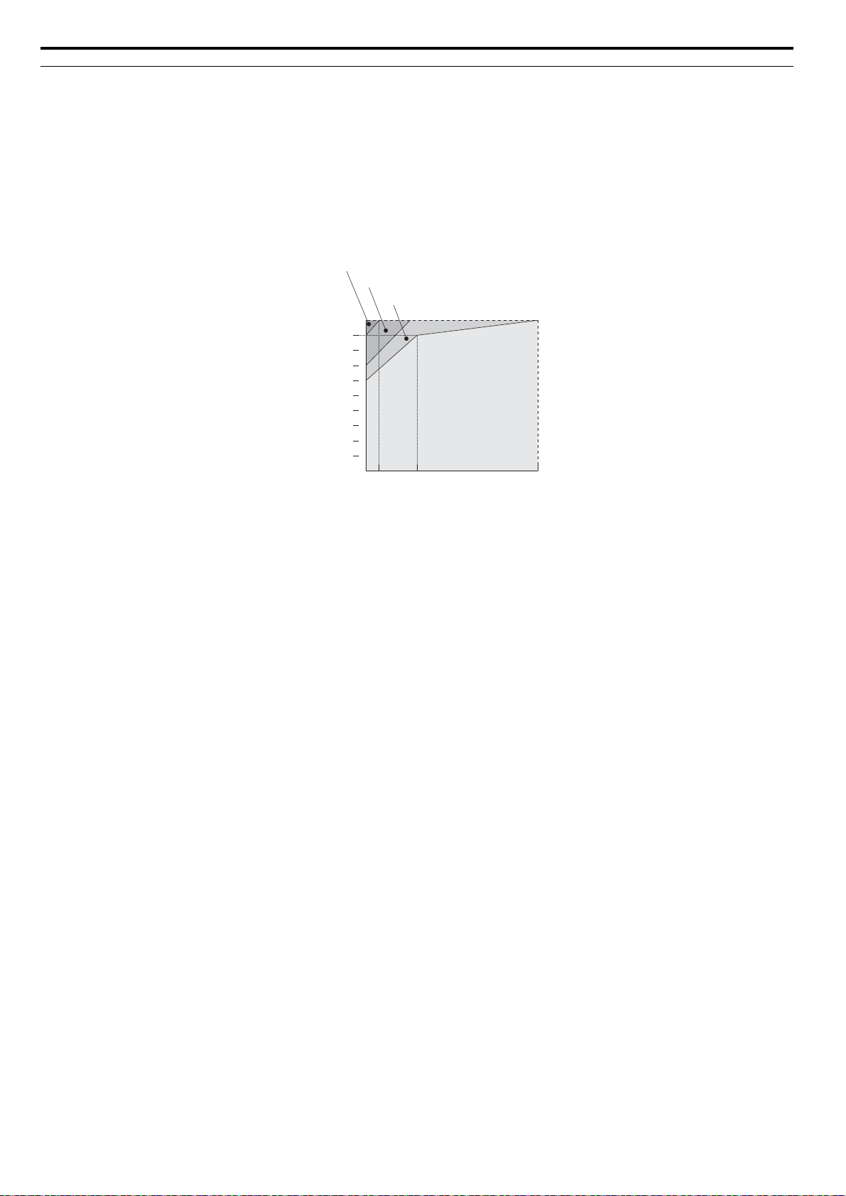
Installing a Reactor
An AC or DC reactor can be used for the following:
• to suppress harmonic current.
• to smooth peak current that results from capacitor switching.
• when the power supply is above 600 kVA.
• when the drive is running from a power supply system with thyristor converters.
Note: A DC reactor is built in to 200 V and 400 V class models with a capacity of 22 kW and higher (HD rating).
Figure i.1
4000
Power supply harmonics
reactor required
Power Supply
Capacity (kVA)
600
0
Drive Capacity (kVA)
Figure i.1 Installing a Reactor
Reactor
unnecessary
60 400
YASKAWA ELECTRIC SIEP C710616 21A YASKAWA AC Drive - A1000 Technical Manual 17
Page 18

i.2 General Safety
Drive Capacity
For specialized motors, make sure that the motor rated current is less than rated output current for the drive. When
running more than one motor in parallel from a single drive, the capacity of the drive should be larger than 1.1 times of
the total motor rated current.
Starting Torque
The overload rating for the drive determines the starting and accelerating characteristics of the motor. Expect lower
torque than when running from line power. To get more starting torque, use a larger drive or increase both the motor and
drive capacity.
Emergency Stop
When the drive faults out, a protective circuit is activated and drive output is shut off. This, however, does not stop the
motor immediately. Some type of mechanical brake may be needed if it is necessary to halt the motor faster than the Fast
Stop function is able to.
Options
The B1, B2, +1, +2, and +3 terminals are used to connect optional devices. Connect only A1000-compatible devices.
Repetitive Starting/Stopping
Cranes (hoists), elevators, punching presses, and other such applications with frequent starts and stops often exceed
150% of their rated current values. Heat stress generated from repetitive high current can shorten the life span of the
IGBTs. The expected lifesaving for the IGBTs is about 8 million start and stop cycles with a 4 kHz carrier frequency and
a 150% peak current.
Yaskawa recommends lowering the carrier frequency, particularly when audible noise is not a concern. The user can also
choose to reduce the load, increase the acceleration and deceleration times, or switch to a larger drive. This will help keep
peak current levels under 150%. Be sure to check the peak current levels when starting and stopping repeatedly during
the initial test run, and make adjustments accordingly.
For crane-type applications using the inching function in which the motor is quickly started and stopped, Yaskawa
recommends the following to ensure motor torque levels:
• Select a large enough drive so that peak current levels remain below 150% of the drive rated current.
• The drive should be one frame size larger than the motor.
■
Installation
Enclosure Panels
Keep the drive in a clean environment by either selecting an area free of airborne dust, lint, and oil mist, or install the
drive in an enclosure panel. Be sure to leave the required space between drives to provide for cooling, and that proper
measures are taken so that the ambient temperature remains within allowable limits. Keep flammable materials away
from the drive. If the drive must be used in an area where it is subjected to oil mist and excessive vibration, protective
designs are available. Contact Yaskawa or your Yaskawa agent for details.
Installation Direction
The drive should be installed upright as specified in the manual. For more information on installation, Refer to
Mechanical Installation on page 40.
■
Settings
Motor Code
If using OLV/PM designed for permanent magnet motors, make sure that the proper motor code has been set to
parameter E5-01 before performing a trial run.
Upper Limits
The drive is capable of running the motor up to 400 Hz. Due to the danger of accidentally of operating at high speed, be
sure to set the upper limit for the frequency. The default setting for the maximum output frequency is 60 Hz.
DC Injection Braking
Motor overheat can result if there is too much current used during DC Injection Braking, or if the time for DC Injection
Braking is too long.
18 YASKAWA ELECTRIC SIEP C710616 21A YASKAWA AC Drive - A1000 Technical Manual
Page 19

i.2 General Safety
Acceleration/Deceleration Times
Acceleration and deceleration times are affected by how much torque the motor generates, the load torque, and the inertia
moment ((GD2)/4). Set a longer accel/decel time when Stall Prevention is enabled. The accel/decel times are lengthened
for as long as the Stall Prevention function is operating. For faster acceleration and deceleration, install one of the
braking options available or increase the capacity of the drive.
■
Compliance with Harmonic Suppression Guidelines
A1000 conforms to strict guidelines in Japan covering harmonic suppression for power conversion devices. Defined in
JEM-TR201 and JEM-TR226 and published by the Japan Electrical Manufacturers’ Association, these guidelines define
the amount of harmonic current output acceptable for new installation. Instructions on calculation harmonic output are
available at www.e-mechatronics.com.
General Handling
■
Wiring Check
Never connect the power supply lines to output terminals U/T1, V/T2, or W/T3. Doing so will destroy the drive. Be sure
to perform a final check of all sequence wiring and other connections before turning the power on. Make sure there are
no short circuits on the control terminals (+V, AC, etc.), as this could damage the drive.
Magnetic Contactor Installation
Avoid switching a magnetic contactor on the power supply side more frequently than once every 30 minutes. Frequent
switching can cause damage to the drive.
Inspection and Maintenance
Capacitors in the drive take time to discharge even after the power has been shut off. After shutting off the power, wait
for at least the amount of time specified on the drive before touching any components..
The heatsink can become quite hot during operation, and proper precautions should be taken to prevent burns. When
replacing the cooling fan, shut off the power and wait at least 15 minutes to be sure that the heatsink has cooled down.
Even when the power has been shut off for a drive running a PM motor, voltage continues to be generated at the motor
terminals while the motor coasts to stop. Take the precautions described below to prevent shock and injury:
• Applications where the machine can still rotate even though the drive has fully stopped should have a load switch
installed to the output side of the drive. Yaskawa recommends manual load switches from the AICUT LB Series by
AICHI Electric Works Co., Ltd.
• Do not attempt to move a load that could potentially rotate the motor faster than the maximum allowable r/min even
when the drive has been shut off.
• Wait for at least the time specified on the warning label after opening the load switch on the output side before
inspecting the drive or performing any maintenance.
• Do not open and close the load switch while the motor is running, as this can damage the drive.
• If the motor is coasting, make sure the power to the drive is turned on and the drive output has completely stopped
before closing the load switch.
Wiring
All wire ends should use ring terminals for UL/cUL compliance. Use only the tools recommended by the terminal
manufacturer for crimping.
Transporting the Drive
Never steam clean the drive.
During transport, keep the drive from coming into contact with salts, fluorine, bromine, phthalate ester, and other such
harmful chemicals.
YASKAWA ELECTRIC SIEP C710616 21A YASKAWA AC Drive - A1000 Technical Manual 19
Page 20
i.2 General Safety
◆ Notes on Motor Operation
■ Using a Standard Motor
Low Speed Range
The cooling fan of a standard motor is usually designed to sufficiently cool the motor at the rated speed. As the selfcooling capability of such a motor reduces with the speed, applying full torque at low speed will possibly damage the
motor. To prevent motor damage from overheat, reduce the load torque as the motor slows. Figure i.2 shows the
allowable load characteristics for a Yaskawa standard motor. A motor designed specifically for operation with a drive
should be used when 100% continuous torque is needed at low speeds.
Figure i.2
Torque
(%)
25% ED (or 15 min)
40% ED (or 20 min)
60% ED (or 40 min)
100
90
80
70
60
50
Continuous operation
36
Figure i.2 Allowable Load Characteristics for a Yaskawa Motor
20
Frequency (Hz)
60
Insulation Tolerance
Consider voltage tolerance levels and insulation in applications with an input voltage of over 440 V or particularly long
wiring distances. Contact Yaskawa or your Yaskawa agent for consultation.
High Speed Operation
Problems may occur with the motor bearings and dynamic balance of the machine when operating a motor beyond its
rated speed. Contact the motor or machine manufacturer.
Torque Characteristics
Torque characteristics differ compared to operating the motor directly from line power. The user should have a full
understanding of the load torque characteristics for the application.
Vibration and Shock
A1000 lets the user choose between high carrier PWM control and low carrier PWM. Selecting high carrier PWM can
help reduce motor oscillation.
Take particular caution when using a variable speed drive for an application that is conventionally run from line power at
a constant speed. If resonance occurs shock-absorbing rubber should be installed around the base of the motor and the
Jump frequency selection should be enabled to prevent continuous operation in the resonant frequency range.
Audible Noise
Noise created during run varies by the carrier frequency setting. When using a high carrier frequency, audible noise from
the motor is comparable to the motor noise generated when running from line power. Operating above the rated r/min,
however, can create unpleasant motor noise.
Using a Synchronous Motor
■
• Contact Yaskawa or your Yaskawa agent if you plan to use any other synchronous motor not endorsed by Yaskawa.
• Synchronous motors cannot be started directly from line power. Applications requiring line power to start should use
an induction motor with the drive.
• A single drive is not capable of running multiple synchronous motors at the same time. Use a standard induction motor
for such setups.
20 YASKAWA ELECTRIC SIEP C710616 21A YASKAWA AC Drive - A1000 Technical Manual
Page 21

i.2 General Safety
• At start, a synchronous motor may rotate slightly in the opposite direction of the Run command depending on
parameter settings and motor type.
• The amount of starting torque that can be generated differs by each control mode and by the type of motor being used.
Set up the motor with the drive after verifying the starting torque, allowable load characteristics, impact load tolerance,
and speed control range.
Contact Yaskawa or your Yaskawa agent if you plan to use a motor that does not fall within these specifications.
• In Open Loop Vector Control for PM motors, braking torque is less than 125% when running between 20% to 100%
speed, even with a braking resistor. Braking torque drops to less than half when running at less than 20% speed.
• In Open Loop Vector Control for PM motors, the allowable load inertia moment is approximately 50 times higher than
the motor inertia moment or less. Contact Yaskawa or your Yaskawa agent concerning applications with a larger inertia
moment.
• When using a holding brake in Open Loop Vector Control for PM motors, release the brake prior to starting the motor.
Failure to set the proper timing can result in speed loss. Not for use with conveyor, transport, or hoist type applications.
• To restart a coasting motor rotating at over 200 Hz while in the V/f control mode, use the Short Circuit Braking
function to first bring the motor to a stop. Short Circuit Braking requires a special braking resistor. Contact Yaskawa or
your Yaskawa agent for details.
Speed Search can be used to restart a coasting motor rotating slower than 200 Hz. If the motor cable is relatively long,
however, the motor should instead be stopped using Short Circuit Braking, which forces the motor to stop by creating a
short-circuit in the motor windings.
◆ Applications with Specialized Motors
■ Applications with Specialized Motors
Multi-Pole Motor
Because the rated current will differ from a standard motor, be sure to check the maximum current when selecting a
drive. Always stop the motor before switching between the number of motor poles. If a regen overvoltage fault occurs or
if overcurrent protection is triggered, the motor will coast to stop.
Submersible Motor
Because motor rated current is greater than a standard motor, select the drive capacity accordingly. Be sure to use a large
enough motor cable to avoid decreasing the maximum torque level on account of voltage drop caused by a long motor
cable.
Explosion-Proof Motor
Both the motor and drive need to be tested together to be certified as explosion-proof. The drive is not designed for
explosion proof areas.
Furthermore, if an encoder is attached to an explosion-proof motor make sure the encoder is explosion-proof too. Use an
insulating signal converter for connecting the encoder signal lines to the drives speed feedback option card.
Geared Motor
To avoid gear damage when operating at low speeds or very high speeds, make sure that both the gear and lubricant are
rated for the desired speed range. Consult with the manufacturer for applications that require operation outside the rated
speed range of the motor or gear box.
Single-Phase Motor
Variable speed drives are not designed for operation with single phase motors. Using capacitors to start the motor causes
excessive current to flow and can damage drive components. A split-phase start or a repulsion start can end up burning
out the starter coils because the internal centrifugal switch is not activated. A1000 is for use with 3-phase motors only.
Uras Vibrator
Uras vibrator is a vibration motor that gets power from centrifugal force by rotating unbalanced weights on both ends of
the shaft. After considering the points below, consult with a your Yaskawa representative to determine the best solution
for the application.
• Uras vibrator should be used within the drive rated frequency.
• Use V/f Control.
YASKAWA ELECTRIC SIEP C710616 21A YASKAWA AC Drive - A1000 Technical Manual 21
Page 22

i.2 General Safety
WARNING
Read manual before installing.
Wait 5 minutes for capacitor
discharge after disconnecting
power supply.
To conform to requirements,
make sure to ground the supply
neutral for 400V class.
After opening the manual switch
between the drive and motor,
please wait 5 minutes before
inspecting, performing
maintenance or wiring the drive.
Risk of electric shock.
Hot surfaces
Top and Side surfaces may
become hot. Do not touch.
●
●
●
●
●
LO
RE
ESC
RUN STOP
ENTERRESET
ALM
DIGITAL OPERATOR JVOP-182
CIMR-AA2A0021FAA
200V 3Phase 5.5kW/3.7kW
REV DRV FOUT
S/N:
危 険
据え付け、運転の前には必ず取扱説明書を読むこと。
通電中および電源遮断後5分以内はフロントカバー
を外さない事。
400V級インバータの場合は、電源の中性点が接地
されていることを確認すること。(対応)
保守・点検、配線を行う場合は、出力側開閉器を
遮断後5分待って実施してください。
けが.感電のおそれがあります。
高温注意
インバータ上部、両側面は高温になります。
触らないでください。
●
●
●
●
AVERTISSMENT
NPJT31470-1
Lire le manuel avant l'installation.
Attendre 5 minutes après la coupure
de l'alimentation, pour permettre
la décharge des condensateurs.
Pour répondre aux exigences , s
assurer que le neutre soit relié
à la terre, pour la série 400V.
Après avoir déconnécte la protection
entre le driver et le moteur, veuillez
patienter 5 minutes avain d’effectuer
une opération de montage ou de
câblage du variateur.
Risque de décharge électrique.
Surfaces Chaudes
Dessus et cotés du boitier Peuvent
devenir chaud. Ne Pas toucher.
WARNING
Read manual before installing.
Wait 5 minutes for capacitor
discharge after disconnecting
power supply.
To conform to requirements,
make sure to ground the supply
neutral for 400V class.
After opening the manual switch
between the drive and motor,
please wait 5 minutes before
inspecting, performing
maintenance or wiring the drive.
Risk of electric shock.
Hot surfaces
Top and Side surfaces may
become hot. Do not touch.
●
●
●
●
●
●
●
●
●
●
●
●
●
●
●
Warning Label
• Increase the acceleration time five to fifteen times longer than would normally be used due to the high amount of load
inertia of an Uras vibrator. Increase drive capacity for applications that require an acceleration time of less than 5 s.
• Drive may have trouble starting due to undertorque that results from erratic torque (static friction torque at start).
Motor with Brake
Caution should be taken when using a drive to operate a motor with a built-in holding brake. If the brake is connected to
the output side of the drive, it may not release at start due to low voltage levels. A separate power supply should be
installed for the motor brake. Motors with a built-in brake tend to generate a fair amount of noise when running at low
speeds.
Power Driven Machinery (decelerators, belts, chains, etc.)
■
Continuous operation at low speeds wears on the lubricating material used in gear box type systems to accelerate and
decelerate power driven machinery. Caution should also be taken when operating at speeds above the rated machine
speed due to noise and shortened performance life.
◆ Drive Label Warnings
Always heed the warning information listed in Figure i.3 in the position shown in Figure i.4.
Figure i.3
Figure i.3 Warning Information
Figure i.4
22 YASKAWA ELECTRIC SIEP C710616 21A YASKAWA AC Drive - A1000 Technical Manual
Figure i.4 Warning Information Position
Page 23

i.2 General Safety
◆ Warranty Information
■ Warranty Period
This drive is warranted for 12 months from the date of delivery to the customer or 18 months from the date of shipment
from the Yaskawa factory, whichever comes first.
■ Scope of Warranty
Inspections
Customers are responsible for periodic inspections of the drive. Upon request, a Yaskawa representative will inspect the
drive for a fee. If the Yaskawa representative finds the drive to be defective due to Yaskawa workmanship or materials
and the defect occurs during the warranty period, this inspection fee will be waived and the problem remedied free of
charge.
Repairs
If a Yaskawa product is found to be defective due to Yaskawa workmanship or materials and the defect occurs during the
warranty period, Yaskawa will provide a replacement, repair the defective product, and provide shipping to and from the
site free of charge.
However, if the Yaskawa Authorized Service Center determines that the problem with the drive is not due to defective
workmanship or materials, the customer will be responsible for the cost of any necessary repairs. Some problems that are
outside the scope of this warranty are:
Problems due to improper maintenance or handling, carelessness, or other reasons where the customer is determined to
be responsible.
Problems due to additions or modifications made to a Yaskawa product without Yaskawa’s understanding.
Problems due to the use of a Yaskawa product under conditions that do not meet the recommended specifications.
Problems caused by natural disaster or fire.
After the free warranty period elapses.
Replenishment or replacement of consumables or expendables.
Defective products due to packaging or fumigation.
Malfunction or problems caused by program that has been made by customers using DriveWorksEZ.
Other problems not due to defects in Yaskawa workmanship or materials.
Warranty service is only applicable within Japan. However, after-sales service is available for customers outside of Japan
for a reasonable fee.
Contact your local Yaskawa representative for more information.
Exceptions
Any inconvenience to the customer or damage to non-Yaskawa products due to Yaskawa’s defective products whether
within or outside of the warranty period are NOT covered by warranty.
Restrictions
■
A1000 was not designed or manufactured for use in devices or systems that may directly affect or threaten human lives
or health.
Customers who intend to use the product described in this manual for devices or systems relating to transportation, health
care, space aviation, atomic power, electric power, or in underwater applications must first contact their Yaskawa
representatives or the nearest Yaskawa sales office.
This product has been manufactured under strict quality-control guidelines. However, if this product is to be installed in
any location where failure of this product could involve or result in a life-and-death situation or loss of human life or in a
facility where failure may cause a serious accident or physical injury, safety devices must be installed to minimize the
likelihood of any accident.
YASKAWA ELECTRIC SIEP C710616 21A YASKAWA AC Drive - A1000 Technical Manual 23
Page 24

i.2 General Safety
24 YASKAWA ELECTRIC SIEP C710616 21A YASKAWA AC Drive - A1000 Technical Manual
Page 25

1
Receiving
This chapter explains how to inspect the drive upon receipt, and gives and overview of the
different enclosure types and components.
1.1 SECTION SAFETY. . . . . . . . . . . . . . . . . . . . . . . . . . . . . . . . . . . . . . . . . . . . . . . . . . . 26
1.2 GENERAL DESCRIPTION. . . . . . . . . . . . . . . . . . . . . . . . . . . . . . . . . . . . . . . . . . . . . 27
1.3 MODEL NUMBER AND NAMEPLATE CHECK . . . . . . . . . . . . . . . . . . . . . . . . . . . . 29
1.4 DRIVE MODELS AND ENCLOSURE TYPES . . . . . . . . . . . . . . . . . . . . . . . . . . . . . . 31
1.5 COMPONENT NAMES . . . . . . . . . . . . . . . . . . . . . . . . . . . . . . . . . . . . . . . . . . . . . . . 32
YASKAWA ELECTRIC SIEP C710616 21A YASKAWA AC Drive - A1000 Technical Manual 25
Page 26

1.1 Section Safety
CAUTION
NOTICE
1.1 Section Safety
Do not carry the drive by the front cover or the terminal cover.
Failure to comply may cause the main body of the drive to fall, resulting in minor or moderate injury.
Observe proper electrostatic discharge procedures (ESD) when handling the drive and circuit boards.
Failure to comply may result in ESD damage to the drive circuitry.
A motor connected to a PWM drive may operate at a higher temperature than a utility-fed motor and the
operating speed range may reduce motor cooling capacity.
Ensure that the motor is suitable for drive duty and/or the motor service factor is adequate to accommodate the
additional heating with the intended operating conditions.
26 YASKAWA ELECTRIC SIEP C710616 21A YASKAWA AC Drive - A1000 Technical Manual
Page 27

1.2 General Description
Receiving
1
1.2 General Description
◆ A1000 Model Selection
Table 1 .1 gives a reference for drive selection depending on the motor power and Normal or Heavy Duty rating.
Note: The models and capacities in shown here are based on standard settings and operation conditions. Derating is required for higher
carrier frequencies and higher ambient temperatures.
Table 1.1 A1000 Models
Motor Power
(kW)
0.4 2A0004 3.2 <1> – – 4A0002 1.8 – –
0.75 2A0006 5 <1> 2A0004 3.5 4A0004 3.4 4A0002 2.1
1.1 2A0008 6.9 <1> 2A0006 6 – – – –
1.5 2A0010 8 <1> 2A0008 8 4A0005 4.8 4A0004 4.1
2.2 2A0012 11 <1> 2A0010 9.6 4A0007 5.5 4A0005 5.4
3.0 2A0018 14 <1> 2A0012 12 4A0009 7.2 4A0007 6.9
3.7 2A0021 17.5 <1> 2A0018 17.5 4A0011 9.2 4A0009 8.8
5.5 2A0030 25 <1> 2A0021 21 4A0018 14.8 4A0011 11.1
7.5 2A0040 33 <1> 2A0030 30 4A0023 18 4A0018 17.5
11 2A0056 47 <1> 2A0040 40 A 4A0031 24 <1> 4A0023 23
15 2A0069 60 <1> 2A0056 56 A 4A0038 31 <1> 4A0031 31
18.5 2A0081 75 <1> 2A0069 69 A 4A0044 39 <1> 4A0038 38
22 2A0110 85 <1> 2A0081 81 A 4A0058 45 <1> 4A0044 44
30 2A0138 115 <1> 2A0110 110 A 4A0072 60 <1> 4A0058 58
37 2A0169 145 <2> 2A0138 138 A 4A0088 75 <1> 4A0072 72
45 2A0211 180 <2> 2A0169 169 A 4A0103 91 <1> 4A0088 88
55 – – 2A0211 211 A 4A0139 112 <2> 4A0103 103
75 – – – – 4A0165 150 <2> 4A0139 139
90 – – – – – – 4A0165 165
Heavy Duty Rating Normal Duty Rating Heavy Duty Rating Normal Duty Rating
Model CIMR-A
3-Phase 200 V Class 3-Phase 400 V Class
Rated Output
Current (A)
Model CIMR-A
Rated Output
Current (A)
Model CIMR-A
<3>
Rated Output
Current (A)
Model CIMR-A
Rated Output
Current (A)
<3>
<1> These values assume the carrier frequency is set to 8 kHz.
<2> These values assume the carrier frequency is set to 5 kHz.
<3> These values assume the carrier frequency is set to 2 kHz.
Note: Current derating is required when setting the carrier frequency higher. Refer to Carrier Frequency Derating on page 370 for
details.
YASKAWA ELECTRIC SIEP C710616 21A YASKAWA AC Drive - A1000 Technical Manual 27
Page 28

1.2 General Description
◆ Control Mode Selection
Table 1 .2 gives an overview of the A1000 control modes and their various features.
Table 1.2 Control Modes and their Features
Motor Type Induction Motors Permanent Magnet Motors Comments
Control Mode V/f V/f w/PG OLV CLV OLV/PM AOLV/PM CLV/PM –
Parameter Setting A1-02 = 0 A1-02 = 1 A1-02 = 2 A1-02 = 3 A1-02 = 5 A1-02 = 6 A1-02 = 7
Basic Description
Motor Type IM IM IM IM PM IPM PM –
Multi Motor YES N/A N/A N/A N/A N/A N/A –
Motor data
unknown
High Speed
Typ e o f
Applications
PG Option Card N/A
Control
Characteristics
Application-
Specific
Accuracy
High Speed
Response
Zero Speed
Control
Torque Control
Operation
Torque Limit
Operation
Speed Control
Range
Speed Accuracy ±2 to 3% ±0.03% ±0.2% ±0.02% ±0.2% ±0.2% ±0.02%
Speed Response
Starting Torque 150% at 3 Hz 150% at 3 Hz
Auto-Tuning
Tor que Li mi t N/A N/A YES YES N/A YES YES
Torque Control N/A N/A N/A YES N/A N/A YES
Droop Function N/A N/A N/A YES N/A N/A YES –
Zero Servo
Control
Speed Search YES YES YES – YES YES YES
Energy-Saving
Control
High Slip
Braking
Feed Forward
Control
Kinetic Energy
Buffering
Overexcitation
Deceleration
Inertia Tuning,
ASR Tuning
Overvoltage
Suppression
High Frequency
Injection
V/f control
V/f control
YES N/A N/A N/A N/A N/A N/A –
N/A YES YES YES YES YES YES –
N/A N/A YES YES N/A YES YES –
N/A N/A N/A YES N/A YES YES –
N/A N/A N/A YES N/A YES YES –
N/A N/A YES YES N/A N/A YES –
1:40 1:40 1:200 1:1500 1:20 1:100 1:1500
3 Hz
(approx.)
• Energy
Saving
Tuning
• Termination
resistor
N/A N/A N/A YES N/A N/A YES Locks the rotor position.
YES YES YES YES N/A
YES YES N/A N/A N/A N/A N/A
N/A N/A N/A YES N/A N/A YES
YES YES YES YES YES YES YES
YES YES YES YES N/A N/A N/A
N/A N/A N/A YES N/A N/A YES
YES YES YES YES YES YES YES
N/A N/A N/A N/A N/A YES N/A
using motor
speed
feedback
PG-B3 or PG-
X3
3 Hz
(approx.)
• Energy
Saving
Tuning
• Termination
resistor
Open Loop
Vector control
N/A
10 Hz 50 Hz 10 Hz 10 Hz 50 Hz
200% at 0.3 Hz200% at 0
• Rotational
• Stationary
• Termination
resistor
Closed Loop
Vector control
PG-B3 or PG-
X3
r/min
• Rotational
• Stationary
• Termination
resistor
•ASR
• Inertia
Open Loop
Vector control
for PM motors
N/A N/A PG-X3 –
100% at 5%
speed
• Stationary
• Termination
resistor
Open Loop
Vector control
for IPM
motors
200% at
0 r/min
• Stationary
• Termination
resistor
YES (IPM
motors only)
Closed Loop
Ve ct o r c o nt r ol
for PM motors
200% at
0 r/min
• Stationary
• Termination
resistor
•ASR
• Inertia
• Encoder
Offset
YES (IPM
motors only)
Default Setting is Open Loop Vector
Control.
–
May fluctuate with characteristics and
motor temperature.
Speed deviation when operating at
constant speed. May fluctuate with
characteristics and motor temperature.
Max. frequency of a speed reference signal
that the drive can follow. May fluctuate
with characteristics and motor temperature.
May fluctuate with characteristics and
motor temperature.
Performance may differ by capacity.
Automatically adjusts parameter settings
that concern electrical characteristics of the
motor.
Sets the maximum torque for the motor to
protect the load and connected machinery.
Allows direct control of motor torque for
tension control and other such applications.
Bi-directional speed detection of a coasting
motor to restart it without stopping.
Saves energy by always operating the
motor at its maximum efficiency.
Increases motor loss to allow for faster
deceleration than normal without the use of
a braking resistor. The effectiveness may
vary based on motor characteristics.
Improves speed accuracy when the load
changes by compensating effects of the
system inertia.
Decelerates the drive to allow it to ride
through a momentary power loss and
continue operation.
Provides fast deceleration without using a
braking resistor.
Provides automatic Speed Control and
Feed Forward function tuning.
Prevents overvoltage by increasing speed
during regeneration. Never use this
function with hoist or crane applications.
Greatly increases the speed control range
of an IPM motor.
28 YASKAWA ELECTRIC SIEP C710616 21A YASKAWA AC Drive - A1000 Technical Manual
Page 29
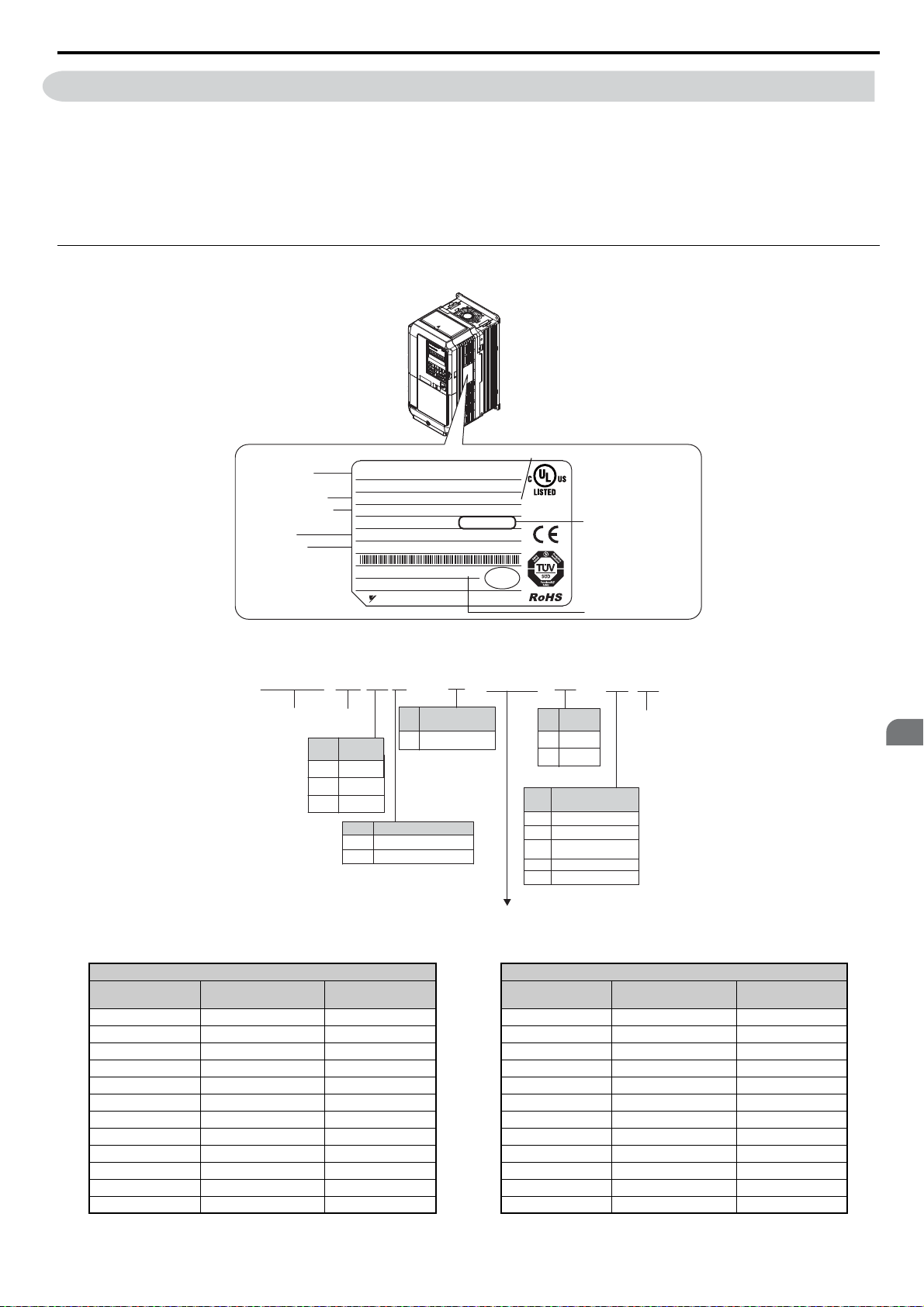
1.3 Model Number and Nameplate Check
Receiving
1
PRG : 1010
IND.CONT.EQ.
7J48 B
CIMR-AA2A0021FAA
YASKAWA ELECTRIC CORPORATION
MADE IN JAPAN
:
: AC3PH 200-240V 50/60Hz 24A/18.9A
: AC3PH 0-240V 0-400Hz 21A/17.5A
: 3.5 kg
:
:
: E131457 IP20
PASS
MODEL
MAX APPLI. MOTOR : 5.5kW / 3.7kW REV : A
INPUT
OUTPUT
MASS
O / N
S / N
FILE NO
TYPE 1 ENCLOSURE
AC drive model
Input specifications
Output specifications
Lot number
Serial number
Software version
Enclosure type
Normal Duty Amps / Heavy Duty Amps
1.3 Model Number and Nameplate Check
Please perform the following tasks after receiving the drive:
• Inspect the drive for damage.
If the drive appears damaged upon receipt, contact the shipper immediately.
• Verify receipt of the correct model by checking the information on the nameplate.
• If you have received the wrong model or the drive does not function properly, contact your supplier.
◆ Nameplate
Figure 1.1
■ Three-Phase 200 V
YASKAWA ELECTRIC SIEP C710616 21A YASKAWA AC Drive - A1000 Technical Manual 29
Figure 1.1 Nameplate Information
CIMR- A A 2 A 0001 F A A
Drive
A1000
Series
Region
No.
Code
UUSA
A Japan
C Europe
No. Voltage Class
2
4
Customized
No.
Specifications
A Standard model
3-phase, 200-240 Vac
3-phase, 380-480 Vac
Normal Duty Heavy Duty
No.
Max. Motor Capacity kWRated Output
Current A
0004 0.75 3.5 0004 0.4 3.2
0006 1.1 6.0 0006 0.75 5
0008 1.5 8.0 0008 1.1 6.9
0010 2.2 9.6 0010 1.5 8
0012 3.0 12 0012 2.2 11
0018 3.7 17.5 0018 3.0 14.0
0021 5.5 21 0021 3.7 17.5
0030 7.5 30 0030 5.5 25
0040 11 40 0040 7.5 33
0056 15 56 0056 11 47
0069 18.5 69 0069 15 60
0081 22 81 0081 18.5 75
Enclosure
No.
Type
A
IP00
FNEMA 1
Environmental
No.
Specification <1>
A
Standard
K Gas-resistant
M
Humidity- and
dust-resistant
Oil-resistant
N
Vibration-resistant
S
No.
Design
Revision
Order
Max. Motor Capacity kWRated Output
Current A
Page 30

1.3 Model Number and Nameplate Check
Normal Duty Heavy Duty
No.
0110 30 110 0110 22 85
0138 37 138 0138 30 115
0169 45 169 0169 37 145
0211 55 211 0211 45 180
Max. Motor Capacity kWRated Output
Current A
■ Three-Phase 400 V
Normal Duty Heavy Duty
No.
0002
0004 1.5 4.1 0004 0.75 3.4
0005 2.2 5.4 0005 1.5 4.8
0007 3.0 6.9 0007 2.2 5.5
0009 3.7 8.8 0009 3.0 7.2
0011 5.5 11.1 0011 3.7 9.2
0018 7.5 17.5 0018 5.5 14.8
0023 11 23 0023 7.5 18
0031 15 31 0031 11 24
0038 18.5 38 0038 15 31
0044 22 44 0044 18.5 39
0058 30 58 0058 22 45
0072 37 72 0072 30 60
0088 45 88 0088 37 75
0103 55 103 0103 45 91
0139 75 139 0139 55 112
0165 90 165 0165 75 150
Max. Motor Capacity kWRated Output
0.75 2.1 0002 0.4 1.8
Current A
No.
No.
Max. Motor Capacity kWRated Output
Max. Motor Capacity kWRated Output
Current A
Current A
<1> Drives with these specifications do not guarantee complete protection for the environmental conditions indicated.
Note: Refer to Drive Models and Enclosure Types on page 31 for differences regarding enclosure protection types and component
descriptions.
30 YASKAWA ELECTRIC SIEP C710616 21A YASKAWA AC Drive - A1000 Technical Manual
Page 31

1.4 Drive Models and Enclosure Types
Receiving
1
1.4 Drive Models and Enclosure Types
Two types of enclosures are offered for A1000 drives.
• IP00/Open-Chassis models are designed for installation in an enclosure panel that serves to protect personnel from
injury caused by accidentally touching live parts.
• IP20/NEMA Type 1 models mount to an indoor wall or in an enclosure panel.
Table 1 .3 describes drive enclosures and models.
Table 1.3 Drive Models and Enclosure Types
Voltage Class
Three-Phase
200 V Class
Three-Phase
400 V Class
IP20/NEMA Type 1 <1>
CIMR-A
2A0004F
2A0006F <2>
2A0008F <2>
2A0010F <2>
2A0012F <2>
2A0018F <2>
2A0021F <2>
2A0030F <2>
2A0040F <2>
2A0056F <2>
2A0069F <2>
2A0081F <2>
2A0110F <2> 2A0110A
2A0138F
<2> 2A0138A
<2> 2A0169A
2A0169F
2A0211F
<2> 2A0211A
4A0002F
4A0004F <2>
4A0005F <2>
4A0007F <2>
4A0009F <2>
4A0011F <2>
4A0018F <2>
4A0023F <2>
4A0031F <2>
4A0038F <2>
4A0044F <2>
4A0058F <2> 4A0058A
<2> 4A0072A
4A0072F
4A0088F
<2> 4A0088A
4A0103F
<2> 4A0103A
<2> 4A0139A
4A0139F
4A0165F
<2> 4A0165A
Enclosure Type
IP00/Open-Chassis
CIMR-A
<2>
<2>
<1> Removing the top cover from a IP20/NEMA Type 1 drive voids NEMA Type 1 protection but still keeps IP20 conformity.
<2> Special order required. Contact your Yaskawa sales representative.
YASKAWA ELECTRIC SIEP C710616 21A YASKAWA AC Drive - A1000 Technical Manual 31
Page 32

1.5 Component Names
N
A
B
C
I
D
E
F
H
G
J
L
M
K
1.5 Component Names
This section gives and overview of the drive components described in this manual.
Note: 1. See Using the Digital Operator on page 83 for a description of the operator keypad.
2. The drive may have no cooling fans or only one cooling fan depending on the model.
◆ IP20/NEMA Type 1 Enclosure
■ Three-Phase AC200 V CIMR-A2A0004F to 0081F
Three-Phase AC400 V CIMR-A4A0002F to 0044F
Figure 1.2
A – Fan cover <1>
B – Cooling fan
<1> I – Protective cover
H – Rubber bushing
C – Mounting hole J – Front cover
D – Heatsink K – USB port (type-B)
E – Optional 24 V DC power supply connector
L – Digital operator
cover
F – Terminal board M – Terminal cover
G – Bottom front cover N – Terminal cover screw
<1> The following drive models have a single cooling fan: CIMR-A2A0018F and 0021F, CIMR-A4A0007F through 0011F.
Drives CIMR-A2A0004F through 0012F and CIMR-A4A0002F through 0005F do not have a cooling fan or a cooling
fan cover.
Figure 1.2 Exploded View of IP20/NEMA Type 1 Components (CIMR-A2A00030F)
32 YASKAWA ELECTRIC SIEP C710616 21A YASKAWA AC Drive - A1000 Technical Manual
Page 33

Receiving
1
◆ IP00/Open-Chassis
L
■ Three-Phase AC200 V CIMR-A2A0110A, 0138A
Three-Phase AC400 V CIMR-A4A0058A, 0103A
Figure 1.3
A
B
C
D
1.5 Component Names
F
E
I
G
J
H
K
A – Fan cover G – Front cover
B – Cooling fan H – USB port (type-B)
C – Mounting hole I – Front cover screw
D – Heatsink J – Digital operator
E – Optional 24 V DC power supply
K – Drive cover
connector cover
F – Terminal board L – Terminal cover
Figure 1.3 Exploded View of IP00/Open Chassis Components (CIMR-A2A0110A)
YASKAWA ELECTRIC SIEP C710616 21A YASKAWA AC Drive - A1000 Technical Manual 33
Page 34

1.5 Component Names
A
B
D
C
E
F
G
H
I
K
J
L
M
■ Three-Phase AC200 V CIMR-A2A0169A, 0211A
Three-Phase AC400 V CIMR-A4A0139A, 0165A
Figure 1.4
A – Mounting hole H – Front cover
B – Heatsink I – USB port (type-B)
C – Optional 24 V DC power supply
J – Digital operator
connector cover
D – Terminal board K – Front cover screw
E – Fan guard L – Drive cover
F – Cooling fan M – Terminal cover
G – Fan unit
Figure 1.4 Exploded view of IP00/Open-Chassis Type Components (CIMR-A4A0165A)
34 YASKAWA ELECTRIC SIEP C710616 21A YASKAWA AC Drive - A1000 Technical Manual
Page 35

Receiving
1
◆ Front Views
A
I
K
J
H
G
F
E
B
CIMR-A2A0012F
C
D
A
G
F
E
B
C
D
K
J
I
CIMR-A2A0110A
Figure 1.5
1.5 Component Names
A – Terminal board connector G – Main circuit terminal (Refer to Wiring
the Main Circuit Terminal on page 65)
B – DIP switch S1 (Refer to Terminal A2
H – Protective cover to prevent miswiring
Analog Input Signal Selection on
page 75)
C – DIP switch S2 (Refer to MEMOBUS/
I – Option card connector (CN5-C)
Modbus Termination on page 77)
D – Sink/source jumper S3 (Refer to
J – Option card connector (CN5-B)
Sinking/Sourcing Mode Switch for
Digital Inputs on page 72)
E – Ground terminal K – Option card connector (CN5-A)
F – Terminal board (Refer to Control
Circuit Wiring on page 66)
Figure 1.5 Front View of Drives
YASKAWA ELECTRIC SIEP C710616 21A YASKAWA AC Drive - A1000 Technical Manual 35
Page 36

1.5 Component Names
36 YASKAWA ELECTRIC SIEP C710616 21A YASKAWA AC Drive - A1000 Technical Manual
Page 37

2
Mechanical Installation
This chapter explains how to properly mount and install the drive.
2.1 SECTION SAFETY. . . . . . . . . . . . . . . . . . . . . . . . . . . . . . . . . . . . . . . . . . . . . . . . . . . 38
2.2 MECHANICAL INSTALLATION . . . . . . . . . . . . . . . . . . . . . . . . . . . . . . . . . . . . . . . . 40
YASKAWA ELECTRIC SIEP C710616 21A YASKAWA AC Drive - A1000 Technical Manual 37
Page 38

2.1 Section Safety
W ARNING
CAUTION
NOTICE
2.1 Section Safety
Fire Hazard
Provide sufficient cooling when installing the drive inside an enclosed panel or cabinet.
Failure to comply could result in overheating and fire.
When multiple drives are placed inside the same enclosure panel, install proper cooling to ensure air entering the
enclosure does not exceed 40 °C.
Crush Hazard
Do not carry the drive by the front cover or the terminal cover.
Failure to comply may result in minor or moderate injury from the main body of the drive falling.
Equipment Hazard
Prevent foreign matter such as metal shavings or wire clippings from falling into the drive during drive
installation and project construction.
Failure to comply could result in damage to the drive.
Place a temporary cover over the top during installation. Be sure to remove the temporary cover before start-up, as the
cover will reduce ventilation and cause the unit to overheat.
Observe proper electrostatic discharge (ESD) procedures when handling the drive.
Failure to comply could result in ESD damage to the drive circuitry.
Operating the motor in the low-speed range diminishes the cooling effects, increases motor temperature, and
may lead to motor damage by overheating.
Reduce the motor torque in the low-speed range whenever using a standard blower cooled motor. If 100% torque is
required continuously at low speed, consider using a special drive or vector-control motor. Select a motor that is
compatible with the required load torque and operating speed range.
The speed range for continuous operation differs according to the lubrication method and motor manufacturer.
If the motor is to be operated at a speed higher than the rated speed, consult with the manufacturer.
Continuously operating an oil-lubricated motor in the low-speed range may result in burning.
When the input voltage is 440 V or higher or the wiring distance is greater than 100 meters, pay special
attention to the motor insulation voltage or use a drive-rated motor with reinforced insulation.
Failure to comply could lead to motor winding failure.
Motor vibration may increase when operating a machine in variable-speed mode, if that machine previously
operated at a constant speed.
Install vibration-proof rubber on the motor base or use the frequency jump function to skip a frequency resonating the
machine.
The motor may require more acceleration torque with drive operation than with a commercial power supply.
Set a proper V/f pattern by checking the load torque characteristics of the machine to be used with the motor.
The rated input current of submersible motors is higher than the rated input current of standard motors.
Select an appropriate drive according to its rated output current. When the distance between the motor and drive is
long, use a cable thick enough to connect the motor to the drive to prevent motor torque reduction.
38 YASKAWA ELECTRIC SIEP C710616 21A YASKAWA AC Drive - A1000 Technical Manual
Page 39

2.1 Section Safety
Mechanical
Installation
2
NOTICE
The current rating differs for a motor with variable pole pitches differs from a standard motor.
Check the maximum current of the motor before selecting the drive capacity. Only switch motor poles when the motor
is stopped. Switching between motor during run will trigger overcurrent protection circuitry or result in overvoltage
from regeneration, and the motor will simply coast to stop.
When using an explosion-proof motor, it must be subject to an explosion-proof test in conjunction with the
drive.
This is also applicable when an existing explosion-proof motor is to be operated with the drive. Since the drive itself is
not explosion-proof, always install it in a safe place.
Never lift the drive up while the cover is removed.
This can damage the terminal board and other components.
YASKAWA ELECTRIC SIEP C710616 21A YASKAWA AC Drive - A1000 Technical Manual 39
Page 40

2.2 Mechanical Installation
2.2 Mechanical Installation
This section outlines specifications, procedures, and the environment for proper mechanical installation of the drive.
◆ Installation Environment
To help prolong the optimum performance life of the drive, install the drive in an environmental matching the
specifications below.
Table 2.1 Installation Environment
Environment Conditions
Installation Area Indoors
-10 °C to +40 °C (IP20/NEMA Type 1)
-10 °C to +50 °C (IP00/Open-Chassis)
Ambient Temperature
Humidity
Storage Temperature
Surrounding Area
Altitude
Vibration
Orientation Install the drive vertically to maintain maximum cooling effects.
Drive reliability improves in environments without wide temperature fluctuations.
When using the drive in an enclosure panel, install a cooling fan or air conditioner in the area to ensure that the air temperature inside the enclosure
does not exceed the specified levels.
Do not allow ice to develop on the drive.
95% RH or less and free of condensation
-20 to +60 °C
Install the drive in an area free from:
• oil mist and dust
• metal shavings, oil, water or other foreign materials
• radioactive materials
• combustible materials (e.g., wood)
• harmful gases and liquids
• excessive vibration
• chlorides
• direct sunlight
1000 m or lower
10 to 20 Hz at 9.8 m/s
20 to 55 Hz at 5.9 m/s2 (up to 200 V 45 kW or 400 V 75 kW) or 2.0 m/s2 (200 V 55 kW or 400 V 90 kW and above)
2
NOTICE: Avoid placing drive peripheral devices, transformers, or other electronics near the drive as the noise created can lead to
erroneous operation. If such devices must be used in close proximity to the drive, take proper steps to shield the drive from noise.
NOTICE: Prevent foreign matter such as metal shavings and wire clippings from falling into the drive during installation. Failure to
comply could result in damage to the drive. Place a temporary cover over the top of the drive during installation. Remove the
temporary cover before startup, as the cover will reduce ventilation and cause the drive to overheat.
40 YASKAWA ELECTRIC SIEP C710616 21A YASKAWA AC Drive - A1000 Technical Manual
Page 41

2.2 Mechanical Installation
Mechanical
Installation
2
OK NG NG
A
A
BB
Side Clearance Top/Bottom Clearance
C
C
D
D
◆ Installation Orientation and Spacing
Install the drive upright as illustrated in Figure 2.1 to maintain proper cooling.
Figure 2.1
Figure 2.1 Correct Installation Orientation
■ Single Drive Installation
Figure 2.2 shows the installation distance required to maintain sufficient space for airflow and wiring. Install the
heatsink against a closed surface to avoid diverting cooling air around the heatsink.
Figure 2.2
A – 50 mm minimum C – 120 mm minimum
B – 30 mm minimum D – Airflow direction
Figure 2.2 Correct Installation Spacing
Note: IP20/NEMA Type 1 and IP00/Open-Chassis models require the same amount of space above and below the drive for installation.
■ Multiple Drive Installation (Side-by-Side Installation)
Models CIMR-A2A0004 through 0081 and 4A0002 through 0044 can take advantage of Side-by-Side installation.
When installing multiple drives into the same enclosure panel, mount the drives according to Figure 2.2.
When mounting drives with the minimum clearance of 2 mm according to Figure 2.3, derating must be considered and
parameter L8-35 must be set to 1. Refer to Temperature Derating on page 371
YASKAWA ELECTRIC SIEP C710616 21A YASKAWA AC Drive - A1000 Technical Manual 41
Page 42

2.2 Mechanical Installation
A
A
A
A
B
C
B
Side Clearance
Line up the tops of the drives.
D
D
Top/Bottom Clearance
Figure 2.3
A – 50 mm minimum C – 2 mm minimum
B – 30 mm minimum
Figure 2.3 Space Between Drives (Side-by-Side Mounting)
Note: When installing drives of different heights in the same enclosure panel, the tops of the drives should line up. Leave space
between the top and bottom of stacked drives for easy cooling fan replacement if required.
D – 120 mm minimum
When drives with IP20/NEMA Type 1 enclosures are mounted side by side, the protective covers of all drives must be
removed as shown in Figure 2.4. Refer to Protective Cover on page 60 to remove and reattach the protective cover.
Figure 2.4
Figure 2.4 IP20/NEMA 1 Side-by-Side Mounting in Enclosure
◆ Digital Operator Remote Usage
■ Remote Operation
The digital operator mounted on the drive can be removed and connected to the drive using an extension cable up to 3 m
long. This makes it easier to operate the drive when it is installed in a location where it can not be accessed easily.
The digital operator can also be permanently mounted in a remote location like a panel door. An extension cable and an
installation support set (depending on the installation type) will be required.
Note: Refer to Drive Options and Peripheral Devices on page 349 for information on extension cables and installation support sets.
42 YASKAWA ELECTRIC SIEP C710616 21A YASKAWA AC Drive - A1000 Technical Manual
Page 43

Mechanical
Installation
2
■ Digital Operator Remote Installation
S /N : J007XE273710001
90
78
60
7. 9
minimum
50
Unit: mm
12. 2
1. 6
Ins tallation holes (2-M 3 scr ews, depth 5)
44
15
Digital Operator
M3 × 6
Phillips recessed
pan head machine screw × 2
Encl osure panel
Unit: mm
Digital Operator Dimensions
Figure 2.5
Figure 2.5 Digital Operator Dimensions
Installation Types and Required Materials
There are two ways the digital operator can be mounted to an enclosure:
2.2 Mechanical Installation
1.
External/face-mount installs the operator outside the enclosure panel
2. Internal/flush-mount installs the operator inside the enclosure panel
Table 2.2 Digital Operator Installation Methods and Required Tools
Installation Method Description Installation Support Sets Model Required Tools
External/Face-Mount
Internal/Flush-Mount
Simplified installation with the digital
operator is mounted on the outside of
the panel with two screws.
Encloses the digital operator in the
panel. The digital operator is flush
with the outside of the panel.
– – Phillips screwdriver (M3)
Installation Support Set A
(for mounting with screws through
holes in the panel)
Installation Support Set B
(for use with threaded studs that are
fixed to the panel)
EZZ020642A Phillips screwdriver (M3, M4)
EZZ020642B
Phillips screwdriver (M3)
Wrench (M4)
Note: Prevent foreign matter such as metal shavings or wire clippings from falling into the drive during installation and project
construction. Failure to comply could result in damage to the drive. Place a temporary cover over the top of the drive during
installation. Remove the temporary cover before startup, as the cover will reduce ventilation and cause the drive to overheat.
External/Face-Mount
1. Cut an opening in the enclosure panel for the digital operator as shown in Figure 2.7.
2. Position the digital operator so the display faces outwards, and mount it to the enclosure panel as shown in
Figure 2.6
Figure 2.6.
YASKAWA ELECTRIC SIEP C710616 21A YASKAWA AC Drive - A1000 Technical Manual 43
Figure 2.6 External/Face-Mount Installation
Page 44

2.2 Mechanical Installation
22
22
14
26
22
78
2
Unit: mm
Figure 2.7
Figure 2.7 Panel Cut-Out Dimensions (External/Face-Mount Installation)
Internal/Flush-Mount
An internal flush-mount requires an installation support set that must be purchased separately. Contact your Yaskawa
representative to order an installation support set and mounting hardware. Figure 2.8 illustrates how to attach the
Installation Support Set A.
1.
Cut an opening in the enclosure panel for the digital operator as shown in Figure 2.9.
2. Mount the digital operator to the installation support.
3. Mount the installation support set and digital operator to the enclosure panel.
Figure 2.8
Enclosure panel
Digital Operator
M4 × 10
Phillips truss head screw × 4
(for panel widths between 1 and 1.6)
Installation Support Set A
M3 × 6
Phillips recessed
pan head machine screw × 2
Unit: mm
Figure 2.8 Internal/Flush Mount Installation
Note: For environments with a significant amount of dust or other airborne debris, use a gasket between the enclosure panel and the
Figure 2.9
digital operator.
+0.5
0
89
120
45
+0.5
59
0
Unit : mm
Figure 2.9 Panel Cut-Out Dimensions (Internal/Flush-Mount Installation)
44 YASKAWA ELECTRIC SIEP C710616 21A YASKAWA AC Drive - A1000 Technical Manual
Page 45

Mechanical
Installation
2
◆ Exterior and Mounting Dimensions
Table 2.3 Drive Models and Types
Protective Design
IP20/NEMA Type 1
IP00/Open-Chassis
Three-Phase
200 V Class
20004F
20006F
20008F
20010F
20012F
20018F
20021F
20030F
20040F
20056F
20069F
20081F
20110A
20138A
20169A
20211A
Drive Model CIMR-A
2.2 Mechanical Installation
Three-Phase
400 V Class
40002F
40004F
40005F
40007F
40009F
40011F
40018F
40023F
40031F
40038F
40044F
–
40058A
40072A
40088A
40103A
40139A
40165A
Page
46
48
YASKAWA ELECTRIC SIEP C710616 21A YASKAWA AC Drive - A1000 Technical Manual 45
Page 46

2.2 Mechanical Installation
W1
4-d
H1
H
H0
H2
H3
W
D
D1
t2
t1
W1
1.5
H
H1
H2
W
D
D1
t1
H2
W1
1.5
H
H0
H1
W
D1
D
t1
H3
Figure 1
Figure 2
Figure 3
4-d
4-d
■ IP20/NEMA Type 1 Drives
46 YASKAWA ELECTRIC SIEP C710616 21A YASKAWA AC Drive - A1000 Technical Manual
Page 47

2.2 Mechanical Installation
Mechanical
Installation
2
Table 2.4 Dimensions for IP20/NEMA Type 1: 200 V Class
Drive Model
CIMR-A2A
0004
0006 140 260 147 122 – 248 6 – 38 5 – M5 3.1
0008 140 260 147 122 – 248 6 – 38 5 – M5 3.2
0010 140 260 147 122 – 248 6 – 38 5 – M5 3.2
0012 140 260 147 122 – 248 6 – 38 5 – M5 3.2
0018 140 260 164 122 – 248 6 – 55 5 – M5 3.5
0021 140 260 164 122 – 248 6 – 55 5 – M5 3.5
0030 140 260 167 122 – 248 6 – 55 5 – M5 4.0
0040 140 260 167 122 – 248 6 – 55 5 – M5 4.0
0056 180 300 187 160 – 284 8 – 75 5 – M5 5.6
0069 220 350 197 192 – 335 8 – 78 5 – M6 8.7
0081
0110
0138 279 614 258 220 450 435 7.5 164 100 2.3 2.3 M6 28
0169 329 730 283 260 550 535 7.5 180 110 2.3 2.3 M6 41
0211 329 730 283 260 550 535 7.5 180 110 2.3 2.3 M6 42
Figure W H D W1 H0 H1 H2 H3 D1 t1 t2 d
140 260 147 122 – 248 6 – 38 5 – M5 3.1
1
<1>
2
<1>
<2>
220 365 197 192 350 335 8 15 78 5 – M6 9.7
254 534 258 195 400 385 7.5 134 100 2.3 2.3 M6 23
3
<1> Removing the top cover from a IP20/NEMA Type 1 drive voids NEMA Type 1 protection but still keeps IP20 conformity.
<2> Special order required. Contact your Yaskawa sales representative.
Dimensions (mm)
Weight
(kg)
Table 2.5 Dimensions for IP20/NEMA Type 1: 400 V Class
Drive Model
CIMR-A4A
0002
0004 140 260 147 122 – 248 6 – 38 5 – M5 3.2
0005 140 260 147 122 – 248 6 – 38 5 – M5 3.2
0007 140 260 164 122 – 248 6 – 55 5 – M5 3.4
0009 140 260 164 122 – 248 6 – 55 5 – M5 3.5
0011 140 260 164 122 – 248 6 – 55 5 – M5 3.5
0018 140 260 167 122 – 248 6 – 55 5 – M5 3.9
0023 140 260 167 122 – 248 6 – 55 5 – M5 3.9
0031 180 300 167 160 – 284 8 – 55 5 – M5 5.4
0038 180 300 187 160 – 284 8 – 75 5 – M5 5.7
0044 220 350 197 192 – 335 8 – 78 5 – M6 8.3
0058
0072 279 515 258 220 450 435 7.5 65 100 2.3 2.3 M6 27
0088 329 630 258 260 510 495 7.5 120 105 2.3 3.2 M6 39
0103 329 630 258 260 510 495 7.5 120 105 2.3 3.2 M6 39
0139 329 730 283 260 550 535 7.5 180 110 2.3 2.3 M6 45
0165 329 730 283 260 550 535 7.5 180 110 2.3 2.3 M6 46
Figure W H D W1 H0 H1 H2 H3 D1 t1 t2 d
140 260 147 122 – 248 6 – 38 5 – M5 3.2
1
<1>
254 465 258 195 400 385 7.5 65 100 2.3 2.3 M6 23
3
<2>
<1> Removing the top cover from a IP20/NEMA Type 1 drive voids NEMA Type 1 protection but still keeps IP20 conformity.
<2> Special order required. Contact your Yaskawa sales representative.
Dimensions (mm)
Weight
(kg)
YASKAWA ELECTRIC SIEP C710616 21A YASKAWA AC Drive - A1000 Technical Manual 47
Page 48

2.2 Mechanical Installation
■ IP00/Open-Chassis Drives
W1
t1
D1
Max 8
W
Table 2.6 Dimensions for IP00/Open-Chassis: 200 V Class
Drive Model
CIMR-A2A
0110
0138 275 450 258 220 435 7.5 100 2.3 2.3 M6 25
0169 325 550 283 260 535 7.5 110 2.3 2.3 M6 37
0211 325 550 283 260 535 7.5 110 2.3 2.3 M6 38
Figure W H D W1 H1 H2 D1 t1 t2 d
250 400 258 195 385 7.5 100 2.3 2.3 M6 21
1
4-d
H
H1
H2
Figure 1
Dimensions (mm)
t2
t1
D1
D
Weight
(kg)
Table 2.7 Dimensions for IP00/Open-Chassis: 400 V Class
Drive Model
CIMR-A4A
0058
0072 275 450 258 220 435 7.5 100 2.3 2.3 M6 25
0088 325 510 258 260 495 7.5 105 2.3 3.2 M6 36
0103 325 510 258 260 495 7.5 105 2.3 3.2 M6 36
0139 325 550 283 260 535 7.5 110 2.3 2.3 M6 41
0165 325 550 283 260 535 7.5 110 2.3 2.3 M6 42
Figure W H D W1 H1 H2 D1 t1 t2 d
250 400 258 195 385 7.5 100 2.3 2.3 M6 21
1
Dimensions (mm)
Weight
(kg)
48 YASKAWA ELECTRIC SIEP C710616 21A YASKAWA AC Drive - A1000 Technical Manual
Page 49

3
Electrical Installation
This chapter explains proper procedures for wiring the control circuit terminals, motor, and
power supply.
3.1 SECTION SAFETY. . . . . . . . . . . . . . . . . . . . . . . . . . . . . . . . . . . . . . . . . . . . . . . . . . . 50
3.2 STANDARD CONNECTION DIAGRAM . . . . . . . . . . . . . . . . . . . . . . . . . . . . . . . . . . 52
3.3 MAIN CIRCUIT CONNECTION DIAGRAM . . . . . . . . . . . . . . . . . . . . . . . . . . . . . . . . 55
3.4 TERMINAL BLOCK CONFIGURATION . . . . . . . . . . . . . . . . . . . . . . . . . . . . . . . . . . 56
3.5 TERMINAL COVER . . . . . . . . . . . . . . . . . . . . . . . . . . . . . . . . . . . . . . . . . . . . . . . . . . 57
3.6 DIGITAL OPERATOR AND FRONT COVER . . . . . . . . . . . . . . . . . . . . . . . . . . . . . . 59
3.7 PROTECTIVE COVER . . . . . . . . . . . . . . . . . . . . . . . . . . . . . . . . . . . . . . . . . . . . . . . . 60
3.8 MAIN CIRCUIT WIRING. . . . . . . . . . . . . . . . . . . . . . . . . . . . . . . . . . . . . . . . . . . . . . . 61
3.9 CONTROL CIRCUIT WIRING . . . . . . . . . . . . . . . . . . . . . . . . . . . . . . . . . . . . . . . . . . 66
3.10 CONTROL I/O CONNECTIONS. . . . . . . . . . . . . . . . . . . . . . . . . . . . . . . . . . . . . . . . 72
3.11 TERMINAL A2 ANALOG INPUT SIGNAL SELECTION . . . . . . . . . . . . . . . . . . . . . 75
3.12 CONNECT TO A PC . . . . . . . . . . . . . . . . . . . . . . . . . . . . . . . . . . . . . . . . . . . . . . . . 76
3.13 MEMOBUS/MODBUS TERMINATION . . . . . . . . . . . . . . . . . . . . . . . . . . . . . . . . . . 77
3.14 EXTERNAL INTERLOCK . . . . . . . . . . . . . . . . . . . . . . . . . . . . . . . . . . . . . . . . . . . . 78
3.15 WIRING CHECKLIST. . . . . . . . . . . . . . . . . . . . . . . . . . . . . . . . . . . . . . . . . . . . . . . . 79
YASKAWA ELECTRIC SIEP C710616 21A YASKAWA AC Drive - A1000 Technical Manual 49
Page 50

3.1 Section Safety
DANGER
W ARNING
3.1 Section Safety
Electrical Shock Hazard
Do not connect or disconnect wiring while the power is on.
Failure to comply will result in death or serious injury.
Electrical Shock Hazard
Do not operate equipment with covers removed.
Failure to comply could result in death or serious injury.
The diagrams in this section may show drives without covers or safety shields to show details. Be sure to reinstall
covers or shields before operating the drives and run the drives according to the instructions described in this manual.
Always ground the motor-side grounding terminal.
Improper equipment grounding could result in death or serious injury by contacting the motor case.
Do not perform work on the drive while wearing loose clothing, jewelry or without eye protection.
Failure to comply could result in death or serious injury.
Remove all metal objects such as watches and rings, secure loose clothing, and wear eye protection before beginning
work on the drive.
Do not remove covers or touch circuit boards while the power is on.
Failure to comply could result in death or serious injury.
Do not allow unqualified personnel to perform work on the drive.
Failure to comply could result in death or serious injury.
Installation, maintenance, inspection, and servicing must be performed only by authorized personnel familiar with
installation, adjustment, and maintenance of AC drives.
Do not touch any terminals before the capacitors have fully discharged.
Failure to comply could result in death or serious injury.
Before wiring terminals, disconnect all power to the equipment. The internal capacitor remains charged even after the
power supply is turned off. After shutting off the power, wait for at least the amount of time specified on the drive
before touching any components.
Fire Hazard
Tighten all terminal screws to the specified tightening torque.
Loose electrical connections could result in death or serious injury by fire due to overheating of electrical connections.
Do not use improper combustible materials.
Failure to comply could result in death or serious injury by fire.
Do not install the drive to a combustible surface. Never place combustible materials on the drive.
Do not use an improper voltage source.
Failure to comply could result in death or serious injury by fire.
Verify that the rated voltage of the drive matches the voltage of the incoming power supply before applying power.
When installing a dynamic braking resistor or optional Braking Resistor Unit, perform all wiring exactly as
specified in the wiring diagrams provided.
Failure to do so can result in fire. Improper wiring may damage braking components.
50 YASKAWA ELECTRIC SIEP C710616 21A YASKAWA AC Drive - A1000 Technical Manual
Page 51

3.1 Section Safety
Electrical Installation
3
CAUTION
NOTICE
Do not carry the drive by the front cover or the terminal cover.
Failure to comply may cause the main body of the drive to fall, resulting in minor or moderate injury.
Observe proper electrostatic discharge procedures (ESD) when handling the drive and circuit boards.
Failure to comply may result in ESD damage to the drive circuitry.
Never connect or disconnect the motor from the drive while the drive is outputting voltage.
Improper equipment sequencing could result in damage to the drive.
Do not use unshielded cable for control wiring.
Failure to comply may cause electrical interference resulting in poor system performance. Use shielded, twisted-pair
wires and ground the shield to the ground terminal of the drive.
Do not allow unqualified personnel to use the product.
Failure to comply could result in damage to the drive or braking circuit.
Carefully review instruction manual TOBPC72060000 when connecting a braking option to the drive.
Do not modify the drive circuitry.
Failure to comply could result in damage to the drive and will void warranty.
Yaskawa is not responsible for any modification of the product made by the user. This product must not be modified.
Check all the wiring to ensure that all connections are correct after installing the drive and connecting any other
devices.
Failure to comply could result in damage to the drive.
YASKAWA ELECTRIC SIEP C710616 21A YASKAWA AC Drive - A1000 Technical Manual 51
Page 52

3.2 Standard Connection Diagram
3.2 Standard Connection Diagram
Connect the drive and peripheral devices as shown in Figure 3.1. It is possible to set and run the drive via the digital
operator without connecting digital I/O wiring. This section does not discuss drive operation; Refer to Start-Up
Programming & Operation on page 81 for instructions on operating the drive.
NOTICE: Inadequate wiring could result in damage to the drive. Install adequate branch circuit short circuit protection per applicable
codes. The drive is suitable for circuits capable of delivering not more than 18,000 RMS symmetrical amperes, 240 Vac maximum (200
V Class) and 480 Vac maximum (400 V Class).
NOTICE: When the input voltage is 440 V or higher or the wiring distance is greater than 100 meters, pay special attention to the
motor insulation voltage or use a drive duty motor. Failure to comply could lead to motor insulation breakdown.
NOTICE: Do not connect AC control circuit ground to drive enclosure. Improper drive grounding can cause control circuit malfunction.
NOTICE: The minimum load for the multi-function relay output MA-MB-MC is 10 mA. If a circuit requires less than 10 mA (reference
value), connect it to a photocoupler output (P1, P2, PC). Improper application of peripheral devices could result in damage to the
photocoupler output of the drive.
52 YASKAWA ELECTRIC SIEP C710616 21A YASKAWA AC Drive - A1000 Technical Manual
Page 53

Electrical Installation
3
Figure 3.1
+
−
+
+
++
+
−
+
−
<4>
<6>
A+
A
B
Z
B+
Z+
AO
IG
BO
IG
ZO
IG
FE
IP
IG
TB1
SD
TB2
B track monitor
A track monitor
M
U/T
1
V/T2
W/T
U
V
W
3
Ground
Cooling fan
PG
M
Terminals -, +1, +2, B1, B2 are
for connection options. Never
connect power supply lines to
these terminals
DC reactor
(option)
UX
Thermal relay
(option)
+
−
+
+
++
+
−
+
−
UX
S
1
S2
S3
S4
S5
S6
S7
MP
DM
DM
RP
A
1
A2
A3
0 V
AC
R
R
S
S
IG
H
1
H2
HC
Drive
B112
B2
2
kΩ
S8
SC
FM
AM
0 V
0 V
AC
FM
AM
AC
E (G)
S
1
S2
<1>
<2>
<3>
<11>
<8>
<12>
<13>
<13>
<9>
<10>
<8>
<7>
<5>
−
VI
+24 V
+V
MA
M
1
M2
P1
P2
MB
MC
PC
CN5-C
CN5-B
CN5-A
Jumper
Braking resistor
(option)
Forward Run / Stop
Reverse Run / Stop
External fault
Fault reset
Multi-speed step 1
Multi-speed step 2
External Baseblock
Jog speed
Multi-function
digtial inputs
(default setting)
Sink / Source mode
selection jumper S3
(default: Sink)
Option board
connectors
Pulse Train Input (max 32 kHz)
Shield ground terminal
Multi-function
analog/ pulse
train inputs
Power supply +10.5 Vdc, max. 20 mA
Analog Input 1
(Frequency Reference Bias)
0 to +10 Vdc (20 kΩ)
Analog Input 2
(Frequency Reference Bias)
0 to +10 Vdc (20 kΩ)
4 to 20 mA / 0 to 20 mA (250 Ω)
Analog Input 3
(Aux. frequency reference)
0 to +10 Vdc (20 kΩ)
−V
Power supply, -10.5 Vdc, max. 20 mA
Safety
switch
MEMOBUS/Modbus
comm. RS485/422
max. 115.2 kBps
Safe Disable inputs
Wire
jumper
Open
Safety relay /
controller
Termination resistor
(120 Ω, 1/2 W)
DIP
Switch S2
DIP Switch S1
Fault relay output
250 Vac, max. 1 A
30 Vdc, max 1 A
(min. 5 Vdc, 10 mA)
Multi-function relay output
(During Run)
250 Vac, max. 1 A
30 Vdc, max 1 A
(min. 5 Vdc, 10 mA)
Multi-function photo coupler output 1
(Zero Speed)
48 Vdc, max 50 mA
Multi-function photo coupler output 2
(Speed Agree 1)
48 Vdc, max 50 mA
Multi-function pulse train output
(Output frequency)
0 to 32 kHz (2.2 kΩ)
Multi-function analog output 1
(Output frequency)
-10 to +10 Vdc (2mA)
Multi-function analog output 2
(Output current)
-10 to +10 Vdc (2mA)
EDM (Safety Electronic Device Monitor)
Main Circuit
Control Circuit
shielded line
twisted-pair shielded line
main circuit terminal
control circuit terminal
PGB3
r1
s1
t1
FU
FV
FW
R/L1
S/L2
T/L3
MCCB
Three-phase
power supply
200 to 400 V
50/60 Hz
R
S
T
ON
OFF
THRX
SA
1
2
TRX
FLT-A
MC
FLT-B
TRX
Fault relay
contact
Braking resistor unit
Thermal relay trip contact
MC
MC
SA
SA
THRX
Fuse
3.2 Standard Connection Diagram
<1> Remove the jumper when installing a DC reactor. Models CIMR-A2A0110 through 0211 and 4A0058 through 0165 come with a built-in
DC reactor.
<2> When installing a braking resistor option, a thermal relay sequence should also be set up to shut off power to the drive in case overheat occurs.
<3> The drive’s protection function for the internal braking transistor needs to be disabled (L8-55 = 0) if using a regen unit such as a regen
converter or some type of braking option unit (and therefore not the internal braking transistor). If left enabled, a braking resistor fault (rF)
may result.
Make sure Stall Prevention is disabled (L3-04 = 0) whenever using a regenerative converter, a regenerative unit, a braking resistor or the
Braking Resistor Unit. If left enabled, the drive may not stop within the specified deceleration time.
<4> Self-cooling motors do not require wiring that would be necessary with motors using a cooling fan.
<5> Supplying power to the control circuit separately from the main circuit requires 24 V power supply (option).
<6> For control modes that do not use a motor speed feedback signal, PG option card wiring is not necessary.
<7> This figure shows an example of a sequence input to S1 through S8 using a non-powered relay or an NPN transistor. Use jumper S3 to select
sink or source, and an internal or external power supply.
<8> The maximum output current capacity for the +V and -V terminals on the control circuit is 20 mA. Never short terminals +V, -V, and AC, as
this can cause erroneous operation or damage the drive.
<9> Set DIP switch S1 to select between a voltage or current input signal to terminal A2. The default setting is for current input.
<10> Enable the termination resistor in the last drive in a MEMOBUS network by setting DIP switch S2 to the ON position.
<11> The sink/source setting for the Safe Disable input is the same as with the sequence input. Jumper S3 has the drive set for an external power
<12> Disconnect the wire jumper between H1 - HC and H2 - HC when utilizing the Safe Disable input.
<13> Monitor outputs work with devices such as analog frequency meters, ammeters, voltmeters, and wattmeters. They are not intended for use as
YASKAWA ELECTRIC SIEP C710616 21A YASKAWA AC Drive - A1000 Technical Manual 53
supply. When not using the Safe Disable input feature, remove the jumper shorting the input and connect an external power supply. Refer to
Figure 3.31 for instructions.
a feedback-type of signal.
Page 54

3.2 Standard Connection Diagram
Figure 3.1 Drive Standard Connection Diagram (example: CIMR-A2A0040)
WARNING! Sudden Movement Hazard. Do not close the wiring for the control circuit unless the multifunction input terminal
parameters are properly set. Improper sequencing of run/stop circuitry could result in death or serious injury from moving equipment.
WARNING! Sudden Movement Hazard. Ensure start/stop and safety circuits are wired properly and in the correct state before
energizing the drive. Failure to comply could result in death or serious injury from moving equipment. When programmed for 3-Wire
control, a momentary closure on terminal S1 may cause the drive to start.
WARNING! When 3-Wire sequence is used, set the drive to 3-Wire sequence before wiring the control terminals and ensure
parameter b1-17 is set to 0 (drive does not accept a run command at power up (default). If the drive is wired for 3-Wire sequence but
set up for 2-Wire sequence (default) and if parameter b1-17 is set to 1 (drive accepts a Run command at power up), the motor will
rotate in reverse direction at power up of the drive and may cause injury.
WARNING! When the application preset function is executed (or A1-06 is set to any value other than 0) the drive I/O terminal functions
change. This may cause unexpected operation and potential damage to equipment or injury.
54 YASKAWA ELECTRIC SIEP C710616 21A YASKAWA AC Drive - A1000 Technical Manual
Page 55

3.3 Main Circuit Connection Diagram
Electrical Installation
3
+3
R/L1
S/L2
T/L3
U/T1
V/T2
W/T3
Braking Unit
(option)
Braking Resistor Unit
(option)
Drive
Motor
−
−
Use terminals and
for DC power supply
+1
−
3 Phase power supply
200 to 240 Vac, 50 to 60 Hz
380 to 480 Vac, 50 to 60 Hz
+1
3.3 Main Circuit Connection Diagram
Refer to diagrams in this section when wiring the drive’s main circuit. Connections may vary based on drive capacity.
The DC power supply for the main circuit also provides power to the control circuit.
NOTICE: Do not use the negative DC bus terminal “-” as a ground terminal. This terminal is at high DC voltage potential. Improper
wiring connections could damage the drive.
◆ Three-Phase 200 V Class (CIMR-A2A0004 to 0081)
Three-Phase 400 V Class (CIMR-A4A0002 to 0044)
Figure 3.2
3 Phase power supply
200 to 240 V
380 to 480 Vac, 50 to 60 Hz
ac, 50 to 60 Hz
Figure 3.2 Connecting Main Circuit Terminals
DC reactor
Jumper
(option)
+1
+2
−
R/L1
S/L2
T/L3
Braking Resistor Unit
B1
B2
Drive
U/T1
V/T2
W/T3
(option)
Motor
◆ Three-Phase 200 V Class (CIMR-A2A0110, 0138)
Three-Phase 400 V Class (CIMR-A4A0058, 0072)
Figure 3.3
B1
Use terminals and
for DC power supply
3 Phase power supply
200 to 240 V
380 to 480 Vac, 50 to 60 Hz
ac, 50 to 60 Hz
+1
+1
−
−
Drive
R/L1
S/L2
T/L3
Figure 3.3 Connecting Main Circuit Terminals
◆ Three-Phase 200 V Class (CIMR-A2A0169, 0211)
Three-Phase 400 V Class (CIMR-A4A0088 to 0165)
Figure 3.4
Braking Resistor Unit
(option)
B2
U/T1
V/T2
W/T3
Motor
YASKAWA ELECTRIC SIEP C710616 21A YASKAWA AC Drive - A1000 Technical Manual 55
Figure 3.4 Connecting Main Circuit Terminals
Page 56

3.4 Terminal Block Configuration
R/L1 S/L2 T/L3 B1 B2 U/T1 V/T2 W/T3
+1 +2
–
U/T1 V/T2 W/T3
+1 +2
R/L1 S/L2 T/L3
–
B1
B2
R/L1 S/L2 T/L3 U/T1 V/T2 W/T3
+1 +2
B1 B2
–
B1 B2
U/T1 V/T2 W/T3
+1 +2
R/L1 S/L2 T/L3
–
R/L1
S/L2
T/L3
B1
B2
U/T1
V/T2
W/T3
1
–
+
R/L1 S/L2 T/L3
U/T1
V/T2 W/T3
–
3
+
1
+
R/L1 S/L2 T/L3
U/T1
V/T2 W/T3
–
3
+
1
+
CIMR-A2A0004, 0006, 0008, 0010,
0012, 0018, 0021ޓ
CIMR-A4A0002, 0004, 0005, 0007,
0009, 0011
CIMR-A2A0030, 0040
CIMR-A4A0018, 0023
CIMR-A2A0056
CIMR-A4A0031, 0038, 0044
CIMR-A2A0069, 0081
CIMR-A4A0088, 0103
CIMR-A2A0110, 0138
CIMR-A4A0058, 0072
CIMR-A2A0169, 0211
CIMR-A4A0139, 0165
3.4 Terminal Block Configuration
Figure 3.6 shows the different main circuit terminal arrangements for the drive capacities.
Figure 3.5
Figure 3.5 Main Circuit Terminal Block Configuration
56 YASKAWA ELECTRIC SIEP C710616 21A YASKAWA AC Drive - A1000 Technical Manual
Page 57

3.5 Terminal Cover
Electrical Installation
3
Connect ground wiring first,
followed by the main circuit,
and then wire the control circuit.
Power lines and signal wiring
exit through the opening provided.
3.5 Terminal Cover
Follow the procedure below to remove the terminal cover for wiring and to reattach the terminal cover after wiring is
complete.
◆ CIMR-A2A0004 to 0081, 4A0002 to 0044 (IP20/NEMA Type 1)
■ Removing the Terminal Cover
1. Loosen the terminal cover screw.
Figure 3.6
Figure 3.6 Removing the Terminal Cover on an IP20/NEMA Type 1 Drive
2. Push in on the tab located on the bottom of the terminal cover, and gently pull forward. This should remove the
Figure 3.7
terminal cover.
Figure 3.7 Removing the Terminal Cover on an IP20/NEMA Type 1 Drive
■ Reattaching the Terminal Cover
Power lines and signal wiring should pass through the opening provided. Refer to Wiring the Main Circuit Terminal on
page 65 and Wiring the Control Circuit Terminal on page 70 for details on wiring.
After all wiring to the drive and other devices is complete, reattach the terminal cover.
Figure 3.8
Figure 3.8 Reattaching the Terminal Cover on an IP20/NEMA Type 1 Drive
YASKAWA ELECTRIC SIEP C710616 21A YASKAWA AC Drive - A1000 Technical Manual 57
Page 58

3.5 Terminal Cover
Connect ground wiring first,
followed by the main circuit,
and then wire the control circuit.
◆ CIMR-A2A0110 to 0211, 4A0058 to 0165 (IP00/Open-Chassis)
■ Removing the Terminal Cover
1. Loosen the four screws on the terminal cover, then pull down on the cover.
CAUTION! Do not completely remove the cover screws, just loosen them. If the cover screws are removed completely, the terminal
cover may fall off causing an injury.
Figure 3.9
Figure 3.9 Removing the Terminal Cover on an IP00/Open-Chassis Drive
2. Pull forward on the terminal cover to free it from the drive.
Figure 3.10
Figure 3.10 Removing the Terminal Cover on an IP00/Open-Chassis Drive
■ Reattaching the Terminal Cover
Once wiring to the terminal board and other devices is complete, double check all connections and finally reattach the
terminal cover. Refer to Wiring the Main Circuit Terminal on page 65 and Wiring the Control Circuit Terminal on
page 70 for details on wiring.
Figure 3.11
Figure 3.11 Reattaching the Terminal Cover on an IP00/Open-Chassis Drive
58 YASKAWA ELECTRIC SIEP C710616 21A YASKAWA AC Drive - A1000 Technical Manual
Page 59

3.6 Digital Operator and Front Cover
Electrical Installation
3
3.6 Digital Operator and Front Cover
The digital operator can be detached from the drive for remote operation, or when the front cover has to be opened to
install an option card.
NOTICE: Be sure the digital operator has been removed prior to opening the front cover or reattaching it. Leaving the digital operator
plugged into the drive when removing the front cover can result in erroneous operation caused by a poor connection. Before
reattaching the operator make sure the front cover has been firmly fastened back into place.
◆ Removing/Reattaching the Digital Operator
■ Removing the Digital Operator
While pinching inwards on the tab located on the right side of the digital operator, pull forward and remove the operator
from the drive.
Figure 3.12
Figure 3.12 Removing the Digital Operator
■ Reattaching the Digital Operator
Insert the digital operator into the opening in the top cover while aligning it with the notches on the left side of the
opening. Next press gently on the right side of the operator until it clicks into place.
Figure 3.13
Figure 3.13 Reattaching the Digital Operator
◆ Removing/Reattaching the Front Cover
■ Removing the Front Cover
After removing the terminal cover and the digital operator, loosen the screw that affixes the front cover (model CIMRA2A0081 does not use a screw to affix the front cover). Pinch inwards on tabs found on each side of the front cover,
then pull forward to remove it from the drive.
Figure 3.14
Figure 3.14 Remove the Front Cover
■ Reattaching the Front Cover
Reverse the instructions given above to reattach the front cover. Pinch inwards on the tabs found on each side of the front
cover while guiding it back into the drive. Make sure it clicks firmly into place.
YASKAWA ELECTRIC SIEP C710616 21A YASKAWA AC Drive - A1000 Technical Manual 59
Page 60

3.7 Protective Cover
Protective Cover
Mounting Holes
3.7 Protective Cover
Drive models CIMR-A2A0004 to 0081 and 4A0002 to 0058 are designed with NEMA Type 1 specifications, and have
a protective cover on the top. Removing this top cover voids the NEMA Type 1 conformance but still keeps a protection
degree in accordance with IP20.
◆ Removing the Protective Cover
Insert the tip of a straight-edge screwdriver into the small openings located on the front edge of the protective cover.
Gently apply pressure as shown in the figure below to free the cover from the drive.
Note: Removing the top cover from a IP20/NEMA Type 1 drive voids the NEMA Type 1 protection but still keeps IP20 conformity.
Figure 3.15
Figure 3.15 Removing the Protective Cover
◆ Reattaching the Protective Cover
Align the small protruding hooks on the sides of the protective cover with the corresponding mounting holes on the top
of the drive. Pinch the hooks inward so that the they connect with the mounting holes and fasten the protective cover
back into place.
Figure 3.16
Figure 3.16 Reattaching the Protective Cover
60 YASKAWA ELECTRIC SIEP C710616 21A YASKAWA AC Drive - A1000 Technical Manual
Page 61

3.8 Main Circuit Wiring
Electrical Installation
3
3.8 Main Circuit Wiring
This section describes the functions, specifications, and procedures required to safely and properly wire the main circuit
in the drive.
NOTICE: Do not solder the ends of wire connections to the drive. Soldered wiring connections can loosen over time. Improper wiring
practices could result in drive malfunction due to loose terminal connections.
NOTICE: Do not switch the drive input to start or stop the motor. Frequently switching the drive on and off shortens the lifetime of the
DC bus charge circuit and the DC bus capacitors, and can cause premature drive failures. For the full performance life, refrain from
switching the drive on and off more than once every 30 minutes.
◆ Main Circuit Terminal Functions
Table 3.1 Main Circuit Terminal Functions
Ter min al Typ e
200 V
Class
400 V
Class
CIMR-A
R/L1
S/L2
T/L3
U/T1
V/T2
W/T3
B1
B2
+2
+1
–
+3
Model
2A0004 to 2A0081 2A0110 to 2A0138 2A0169 to 2A0211
4A0002 to 4A0044 4A0058 to 4A0072 4A0088 to 4A0165
Main circuit power supply input Connects line power to the drive 53
Drive output Connects to the motor 53
Braking resistor not available
• DC reactor connection (+1,
+2) (remove the shorting bar
between +1 and +2)
• DC power supply input (+1,
−)
not available
• DC power supply input
(+1, −)
For 200 V class: 100 Ω or less
For 400 V class: 10 Ω or less
not available
• DC power supply input
(+1, −)
• Braking transistor
connection (+3, −)
Function Page
Available for connecting a braking resistor or a
braking resistor unit option
For connection
• of the drive to a DC power supply (terminals +1
and – are not EU or UL approved)
• of braking options
• connection of a DC reactor
Grounding terminal 65
354
358
◆ Wire Gauges and Tightening Torque
Select the appropriate wires and crimp terminals from Ta bl e 3.2 through Table 3.4.
Note: 1. Wire gauge recommendations based on drive continuous current ratings (ND) using 75°C 600 Vac vinyl-sheathed wire assuming
ambient temperature within 40°C and wiring distance less than 100 m.
2. Terminals +1, +2, +3, –, B1 and B2 are for connecting optional devices such as a DC reactor or braking resistor. Do not connect other
non-specified devices to these terminals.
• Consider the amount of voltage drop when selecting wire gauges. Increase the wire gauge when the voltage drop is
greater than 2% of motor rated voltage. Ensure the wire gauge is suitable for the terminal block. Use the following
formula to calculate the amount of voltage drop:
Line drop voltage (V) = 3 × wire resistance (Ω/km) × wire length (m) × current (A) × 10
• Use terminal +1 and the negative terminal when connecting a braking resistor, regenerative converter, or a regen unit.
• Refer to instruction manual TOBPC72060000 for braking unit or braking resistor unit wire gauges.
• Refer to UL Standards Compliance on page 484 for information on UL compliance.
-3
YASKAWA ELECTRIC SIEP C710616 21A YASKAWA AC Drive - A1000 Technical Manual 61
Page 62

3.8 Main Circuit Wiring
■ Three-Phase 200 V Class
Table 3.2 Wire Gauge and Torque Specifications (Three-Phase 200 V Class)
Model
CIMR-A
2A0004
2A0006
2A0008
2A0010
2A0012
2A0018
2A0021
2A0030
2A0040
2A0056
2A0069
2A0081
2A0110
Ter mi nal
R/L1, S/L2, T/L3 2 2 to 5.5 14 14 to 10 2.5 2.5 to 6
U/T1, V/T2, W/T3 2 2 to 5.5 14 14 to 10 2.5 2.5 to 6
–, +1, +2 2 2 to 5.5 – 14 to 10 – 2.5 to 6
B1, B2 2 2 to 5.5 – 14 to 10 – 2.5 to 6
R/L1, S/L2, T/L3 2 2 to 5.5 12 14 to 10 2.5 2.5 to 6
U/T1, V/T2, W/T3 2 2 to 5.5 14 14 to 10 2.5 2.5 to 6
–, +1, +2 2 2 to 5.5 – 14 to 10 – 2.5 to 6
B1, B2 2 2 to 5.5 – 14 to 10 – 2.5 to 6
R/L1, S/L2, T/L3 3.5 2 to 5.5 10 12 to 10 2.5 2.5 to 6
U/T1, V/T2, W/T3 3.5 2 to 5.5 10 14 to 10 2.5 2.5 to 6
–, +1, +2 3.5 2 to 5.5 – 14 to 10 – 2.5 to 6
B1, B2 2 2 to 5.5 – 14 to 10 – 2.5 to 6
R/L1, S/L2, T/L3 5.5 3.5 to 5.5 10 12 to 10 4 2.5 to 6
U/T1, V/T2, W/T3 3.5 3.5 to 5.5 10 12 to 10 2.5 2.5 to 6
–, +1, +2 5.5 3.5 to 5.5 – 12 to 10 – 4 to 6
B1, B2 2 2 to 5.5 – 14 to 10 – 2.5 to 6
R/L1, S/L2, T/L3 14 5.5 to 14 8 10 to 6 6 4 to 16
U/T1, V/T2, W/T3 8 5.5 to 14 8 10 to 6 6 4 to 16
–, +1, +2 14 5.5 to 14 – 10 to 6 – 6 to 16
B1, B2 3.5 2 to 5.5 – 14 to 10 – 4 to 6
R/L1, S/L2, T/L3 14 14 6 8 to 6 10 6 to 16
U/T1, V/T2, W/T3 14 8 to 14 8 8 to 6 10 6 to 16
–, +1, +2 14 14 – 6 – 16
B1, B2 5.5 3.5 to 5.5 – 12 to 10 – 4 to 6
R/L1, S/L2, T/L3 22 14 to 22 4 6 to 4 16 16 to 25
U/T1, V/T2, W/T3 14 14 to 22 4 6 to 4 16 16 to 25
–, +1, +2 22 14 to 22 – 6 to 4 – 16 to 25
B1, B2 14 5.5 to 14 – 10 to 6 – 6 to 10 M5
R/L1, S/L2, T/L3 30 22 to 30 3 4 to 3 25 16 to 25
U/T1, V/T2, W/T3 22 14 to 30 3 4 to 3 16 16 to 25
–, +1, +2 30 22 to 30 – 4 to 3 – 25
B1, B2 14 8 to 14 – 8 to 6 – 10 to 16 M5
R/L1, S/L2, T/L3 38 30 to 38 2 3 to 2 35 25 to 35
U/T1, V/T2, W/T3 30 22 to 38 2 3 to 2 25 25 to 35
–, +1, +2 38 30 to 38 – 3 to 2 – 25 to 35
B1, B2 14 14 – 6 – 16 M5
R/L1, S/L2, T/L3 38 30 to 50 1/0 3 to 1/0 35 25 to 50
1, V/T2, W/T3 38 30 to
U/T
–, +1 60 38 to 60 – 2 to 1/0 – 35 to 50
B1, B2 22 14 to 50 – 6 to 1/0 – 16 to 50
Recommended
Gauge
mm
2 2 to 5.5 10 14 to 10 2.5 2.5 to 6
3.5 2 to 5.5 10 14 to 10 2.5 2.5 to 6
3.5 2 to 5.5 10 14 to 10 2.5 2.5 to 6
3.5 3.5 to 5.5 10 12 to 10 4 4 to 6
5.5 5.5 to 8 8 10 to 8 6 6 to 10 M5
5.5 5.5 to 8 8 10 to 8 10 6 to 10 M5
8 8 to 14 6 8 to 6 16 10 to 16 M6
8 8 to 22 6 6 to 4 16 16 to 25 M6
14 14 to 22 6 6 to 4 16 16 to 25 M6
14 14 to 38 6 6 to 4 16 16 to 25
For Asia <1> For U.S.A <2> For Europe <3>
Applicable
2
Gauge
mm
Recommended
2
50 1/0 3 to 1/0 35 25 to 50
Gauge
AWG, kc mil
Applicable
Gauge
AWG, kcmil
Recommended
Gauge
2
mm
Applicable
Gauge
mm
Screw
2
Size
M4
M4
M4
M4
M4
M4
M6
M8
M8
M8
Tightening
Tor que
Nxm (lb.in.)
1.2 to 1.5
(10.6 to 13.3)
1.2 to 1.5
(10.6 to 13.3)
1.2 to 1.5
(10.6 to 13.3)
1.2 to 1.5
(10.6 to 13.3)
1.2 to 1.5
(10.6 to 13.3)
2 to 2.5
(17.7 to 22.1)
1.2 to 1.5
(10.6 to 13.3)
2 to 2.5
(17.7 to 22.1)
4 to 6
(35.4 to 53.1)
2 to 2.5
(17.7 to 22.1)
4 to 6
(35.4 to 53.1)
9 to11
(79.7 to 97.4)
2 to 2.5
(17.7 to 22.1)
4 to 6
(35.4 to 53.1)
9 to11
(79.7 to 97.4)
2 to 2.5
(17.7 to 22.1)
4 to 6
(35.4 to 53.1)
9 to 11
(79.7 to 97.4)
62 YASKAWA ELECTRIC SIEP C710616 21A YASKAWA AC Drive - A1000 Technical Manual
Page 63

3.8 Main Circuit Wiring
Electrical Installation
3
Model
CIMR-A
2A0138
2A0169
2A0211
Ter mi nal
R/L1, S/L2, T/L3 60 50 to 80 2/0 1 to 3/0 50 35 to 70
U/T1, V/T2, W/T3 60 50 to 80 2/0 1 to 3/0 50 35 to 70
–, +1 80 60 to 80 – 1/0 to 3/0 – 50 to 70
B1, B2 30 22 to 80 – 4 to 3/0 – 25 to 70
R/L1, S/L2, T/L3 80 60 to 100 4/0 2/0 to 4/0 70 50 to 95
U/T1, V/T2, W/T3 80 60 to 100 4/0 3/0 to 4/0 70 50 to 95
–, +1 50 × 2P 50 to 100 – 1 to 4/0 – 35 to 95
+3 60 50 to 100 – 1/0 to 4/0 – 50 to 95
R/L1, S/L2, T/L3 100 80 to 100 1/0 × 2P 1/0 to 4/0 95 70 to 95
U/T1, V/T2, W/T3 50 × 2P 50 to 100 1/0 × 2P 1/0 to 4/0 95 70 to 95
–, +1 50 × 2P 50 to 100 – 1 to 4/0 – 35 to 95
+3 80 60 to 100 – 1/0 to 4/0 – 50 to 95
Recommended
For Asia <1> For U.S.A <2> For Europe <3>
Gauge
2
mm
22 22 to 38 4 4 25 25 M8
22 22 to 60 4 4 to 2 35 25 to 35 M8
22 22 to 60 4 4 to 1/0 50 25 to 50 M8
Applicable
Gauge
<1> Gauges listed here are for use in Japan.
<2> Gauges listed here are for use in the United States.
<3> Gauges listed here are for use in Europe.
■ Three-Phase 400 V Class
Table 3.3 Wire Gauge and Torque Specifications (Three-Phase 400 V Class)
Model
CIMR-A
4A0002
4A0004
4A0005
4A0007
4A0009
4A0011
4A0018
4A0023
4A0031
Ter mi nal
R/L1, S/L2, T/L3 2 2 to 5.5 14 14 to 10 2.5 2.5 to 6
U/T1, V/T2, W/T3 2 2 to 5.5 14 14 to 10 2.5 2.5 to 6
–, +1, +2 2 2 to 5.5 – 14 to 10 – 2.5 to 6
B1, B2 2 2 to 5.5 – 14 to 10 – 2.5 to 6
R/L1, S/L2, T/L3 2 2 to 5.5 14 14 to 10 2.5 2.5 to 6
U/T1, V/T2, W/T3 2 2 to 5.5 14 14 to 10 2.5 2.5 to 6
–, +1, +2 2 2 to 5.5 – 14 to 10 – 2.5 to 6
B1, B2 2 2 to 5.5 – 14 to 10 – 2.5 to 6
R/L1, S/L2, T/L3 2 2 to 5.5 12 14 to 10 2.5 2.5 to 6
U/T1, V/T2, W/T3 2 2 to 5.5 14 14 to 10 2.5 2.5 to 6
–, +1, +2 2 2 to 5.5 – 14 to 10 – 2.5 to 6
B1, B2 2 2 to 5.5 – 14 to 10 – 2.5 to 6
R/L1, S/L2, T/L3 3.5 2 to 14 10 12 to 6 2.5 2.5 to 16
U/T1, V/T2, W/T3 3.5 2 to 14 10 12 to 6 2.5 2.5 to 16
–, +1, +2 3.5 2 to 14 – 12 to 6 – 4 to 16
B1, B2 2 2 to 5.5 – 12 to 10 – 4 to 6
R/L1, S/L2, T/L3 5.5 3.5 to 14 10 10 to 6 4 2.5 to 16
U/T1, V/T2, W/T3 5.5 3.5 to 14 10 10 to 6 4 2.5 to 16
–, +1, +2 5.5 3.5 to 14 – 12 to 6 – 4 to 16
B1, B2 2 2 to 5.5 – 12 to 10 – 4 to 6
R/L1, S/L2, T/L3 14 5.5 to 14 8 8 to 6 6 6 to 16
U/T1, V/T2, W/T3 8 5.5 to 8 8 10 to 6 6 6 to 16
–, +1, +2 14 5.5 to 14 – 10 to 6 – 6 to 16
B1, B2 3.5 2 to 8 – 10 to 8 – 6 to 10 M5
Recommended
For Asia <1> For U.S.A <2> For Europe <3>
Gauge
2
mm
2 2 to 5.5 12 14 to 12 2.5 2.5 to 4
3.5 2 to 5.5 10 14 to 10 2.5 2.5 to 6
3.5 2 to 5.5 10 14 to 10 2.5 2.5 to 6
3.5 2 to 5.5 10 14 to 10 2.5 2.5 to 6 M5
3.5 3.5 to 5.5 10 12 to 10 4 4 to 6 M5
5.5 5.5 to 8 8 10 to 8 6 6 to 10 M6
Applicable
Gauge
mm
mm
2
2
Recommended
Gauge
AWG, kcmil
Recommended
Gauge
AWG, kcmil
Applicable
Gauge
AWG, kcmil
Applicable
Gauge
AWG, kcmil
Recommended
Gauge
2
mm
Recommended
Gauge
2
mm
Applicable
Gauge
2
mm
Applicable
Gauge
2
mm
Screw
Size
M10
M10
M10
Screw
Size
M4
M4
M4
M4
M4
M5
Tightening
Torque
Nxm (lb.in.)
18 to 23
(159 to 204)
9 to 11
(79.7 to 97.4)
18 to 23
(159 to 204)
9 to 11
(79.7 to 97.4)
18 to 23
(159 to 204)
9 to 11
(79.7 to 97.4)
Tightening
Torque
Nxm (lb.in.)
1.2 to 1.5
(10.6 to 13.3)
1.2 to 1.5
(10.6 to 13.3)
1.2 to 1.5
(10.6 to 13.3)
1.2 to 1.5
(10.6 to 13.3)
2 to 2.5
(17.7 to 22.1)
1.2 to 1.5
(10.6 to 13.3)
2 to 2.5
(17.7 to 22.1)
2 to 2.5
(17.7 to 22.1)
2 to 2.5
(17.7 to 22.1)
4 to 6
(35.4 to 53.1)
YASKAWA ELECTRIC SIEP C710616 21A YASKAWA AC Drive - A1000 Technical Manual 63
Page 64

3.8 Main Circuit Wiring
Model
CIMR-A
4A0038
4A0044
4A0058
4A0072
4A0088
4A0103
4A0139
4A0165
Ter mi nal
R/L1, S/L2, T/L3 14 14 6 8 to 6 10 10 to 16
U/T1, V/T2, W/T3 14 8 to 14 8 8 to 6 6 6 to 16
–, +1, +2 14 14 – 6 – 6 to 16
B1, B2 5.5 3.5 to 8 – 10 to 8 – 6 to 10 M5
R/L1, S/L2, T/L3 14 14 to 22 6 6 to 4 16 16 to 25
U/T1, V/T2, W/T3 14 14 to 22 6 6 to 4 16 16 to 25
–, +1, +2 14 14 to 22 – 6 to 4 – 16 to 25
B1, B2 8 5.5 to 8 – 10 to 8 – 6 to 10 M5
R/L1, S/L2, T/L3 14 14 to 50 4 6 to 1/0 16 10 to 50
U/T1, V/T2, W/T3 14 14 to 50 4 6 to 1/0 16 10 to 50
–, +1 22 14 to 50 – 6 to 1/0 – 16 to 50
B1, B2 14 8 to 50 – 8 to 1/0 – 10 to 50
R/L1, S/L2, T/L3 22 14 to 50 3 4 to 1/0 16 16 to 50
U/T1, V/T2, W/T3 22 14 to 50 3 4 to 1/0 25 16 to 50
–, +1 30 22 to 50 – 4 to 1/0 – 25 to 50
B1, B2 14 14 to 50 – 6 to 1/0 – 16 to 50
R/L1, S/L2, T/L3 30 22 to 60 2 3 to 3/0 25 16 to 70
U/T1, V/T2, W/T3 30 22 to 60 2 3 to 3/0 25 25 to 70
–, +1 38 30 to 60 – 3 to 2/0 – 25 to 70
+3 22 14 to 60 – 6 to 3/0 – 16 to 70
R/L1, S/L2, T/L3 38 30 to 60 1/0 2 to 3/0 35 25 to 70
U/T1, V/T2, W/T3 38 30 to 60 1 2 to 3/0 35 25 to 70
–, +1 60 30 to 60 – 3 to 2/0 – 25 to 70
+3 30 22 to 60 – 4 to 3/0 – 25 to 70
R/L1, S/L2, T/L3 60 38 to 100 3/0 1/0 to 4/0 50 35 to 95
U/T1, V/T2, W/T3 60 50 to 100 2/0 1/0 to 4/0 50 35 to 95
–, +1 100 60 to 100 – 1/0 to 4/0 – 50 to 95
+3 50 30 to 100 – 3 to 4/0 – 25 to 95
R/L1, S/L2, T/L3 80 60 to 100 4/0 3/0 to 4/0 70 50 to 95
U/T1, V/T2, W/T3 80 80 to 100 4/0 3/0 to 4/0 70 70 to 95
–,+1 50 Å~ 2P 50 to 100 – 1 to 4/0 – 35 to 95
+3 60 50 to 100 – 1/0 to 4/0 – 50 to 95
Recommended
For Asia <1> For U.S.A <2> For Europe <3>
Gauge
2
mm
8 5.5 to 14 6 10 to 6 10 6 to 16 M6
8 8 to 14 6 8 to 6 16 10 to 16 M6
8 8 to 14 6 8 to 6 16 10 to 16
14 14 to 22 6 6 to 4 16 16 to 25
22 14 to 22 4 6 to 4 16 16 to 25
22 14 to 22 4 6 to 4 16 16 to 25
22 22 4 4 25 25
22 22 to 30 4 4 to 2 35 25 to 35
Applicable
Gauge
<1> Gauges listed here are for use in Japan.
<2> Gauges listed here are for use in the United States.
<3> Gauges listed here are for use in Europe.
mm
2
Recommended
Gauge
AWG, kc mil
Applicable
Gauge
AWG, kcmil
Recommended
Gauge
2
mm
Applicable
Gauge
2
mm
Screw
Size
M5
M6
M8
M8
M8
M8
M10
M10
Tightening
Tor que
Nxm (lb.in.)
2 to 2.5
(17.7 to 22.1)
2 to 2.5
(17.7 to 22.1)
4 to 6
(35.4 to 53.1)
4 to 6
(35.4 to 53.1)
2 to 2.5
(17.7 to 22.1)
4 to 6
(35.4 to 53.1)
9 to 11
(79.7 to 97.4)
9 to 11
(79.7 to 97.4)
9 to 11
(79.7 to 97.4)
9 to 11
(79.7 to 97.4)
18 to 23
(159 to 204)
18 to 23
(159 to 204)
◆ Main Circuit Terminal and Motor Wiring
This section outlines the various steps, precautions, and checkpoints for wiring the main circuit terminals and motor
terminals.
NOTICE: When connecting the motor to the drive output terminals U/T1, V/T2, and W/T3, the phase order for the drive and motor
should match. Failure to comply with proper wiring practices may cause the motor to run in reverse if the phase order is backward.
NOTICE: Do not connect phase-advancing capacitors or LC/RC noise filters to the output circuits. Failure to comply could result in
damage to the drive, phase-advancing capacitors, LC/RC noise filters or ground fault circuit interrupters.
NOTICE: Do not connect the AC power line to the output motor terminals of the drive. Failure to comply could result in death or serious
injury by fire as a result of drive damage from line voltage application to output terminals.
64 YASKAWA ELECTRIC SIEP C710616 21A YASKAWA AC Drive - A1000 Technical Manual
Page 65

3.8 Main Circuit Wiring
Electrical Installation
3
OK OK NG
A
■ Cable Length Between Drive and Motor
Voltage drop along the motor cable may cause reduced motor torque when the wiring between the drive and the motor is
too long, especially at low frequency output. This can also be a problem when motors are connected in parallel with a
fairly long motor cable. Drive output current will increase as the leakage current from the cable increases. An increase in
leakage current may trigger an overcurrent situation and weaken the accuracy of the current detection.
Adjust the drive carrier frequency according to Ta bl e 3.4. If the motor wiring distance exceeds 100 m because of the
system configuration, reduce the ground currents. Refer to C6-02: Carrier Frequency Selection on page 168.
Table 3.4 Cable Length Between Drive and Motor
Cable Length 50 m or less 100 m or less Greater than 100 m
Carrier Frequency 15 kHz or less 5 kHz or less 2 kHz or less
Note: When setting carrier frequency in a drive running multiple motors, calculate the cable length as the total distance of wiring to all
motors that are connected.
■ Ground Wiring
Follow the precautions to wire the ground for one drive or a series of drives.
WARNING! Electrical Shock Hazard. Always use a ground wire that complies with technical standards on electrical equipment and
minimize the length of the ground wire. Improper equipment grounding may cause dangerous electrical potentials on equipment
chassis, which could result in death or serious injury.
WARNING! Electrical Shock Hazard. Be sure to ground the drive ground terminal. (200 V Class: Ground to 100 Ω or less, 400 V
Class: Ground to 10 Ω or less). Improper equipment grounding could result in death or serious injury by contacting ungrounded
electrical equipment.
NOTICE: Do not share the ground wire with other devices such as welding machines or large-current electrical equipment. Improper
equipment grounding could result in drive or equipment malfunction due to electrical interference.
NOTICE: When using more than one drive, ground multiple drives according to instructions. Improper equipment grounding could
result in abnormal operation of drive or equipment.
Refer to Figure 3.17 when using multiple drives. Do not loop the ground wire.
Figure 3.17
Figure 3.17 Multiple Drive Wiring
■ Wiring the Main Circuit Terminal
WARNING! Electrical Shock Hazard. Shut off the power supply to the drive before wiring the main circuit terminals. Failure to comply
may result in death or serious injury.
Wire the main circuit terminals after the terminal board has been properly grounded.
Models CIMR-A2A0004 through 0081 and 4A0002 through 0044 have a cover placed over the DC bus and braking
circuit terminals prior to shipment to help prevent miswiring. Cut away covers as needed for terminals using wire cutters.
Figure 3.18
A – Protective Cover
Figure 3.18 Protecting Cover to Prevent Miswiring (CIMR-A2A0056)
■ Main Circuit Connection Diagram
Refer to Main Circuit Connection Diagram on page 55 when wiring terminals on the drive’s main power circuit.
WARNING! Fire Hazard. The braking resistor connection terminals are B1 and B2. Do not connect braking resistors to any other
terminals. Improper wiring connections could cause the braking resistor to overheat and cause death or serious injury by fire. Failure to
comply may result in damage to the braking circuit or drive.
YASKAWA ELECTRIC SIEP C710616 21A YASKAWA AC Drive - A1000 Technical Manual 65
Page 66

3.9 Control Circuit Wiring
+
−
+
+
+
−
+
−
+
−
+
+
+
−
+
−
S
1
S
2
S
3
S
4
S
5
S
6
S
7
MP
DM
DM
RP
A
1
A
2
A
3
0
V
AC
R
R
S
S
IG
H
1
H
2
HC
Drive
2
kΩ
S
8
SC
FM
AM
0
V
0
V
AC
FM
AM
AC
E (G)
S
1
S
2
<6>
<3>
<5>
<7>
<8>
<8>
<4>
<3>
<2>
<1>
VI
+
24
V
+V
MA
M
1
M
2
P
1
P
2
MB
MC
PC
CN5-C
CN5-B
CN5-A
Forward Run / Stop
Reverse Run / Stop
External fault
Fault reset
Multi-speed step 1
Multi-speed step 2
External Baseblock
Jog speed
Multi-function
digtial inputs
(default setting)
Sink / Source mode
selection jumper S3
(default: Sink)
Option board
connectors
Pulse Train Input (max 32 kHz)
Shield ground terminal
Multi-function
analog/ pulse
train inputs
Power supply +10.5 Vdc, max. 20 mA
Analog Input 1
(Frequency Reference Bias)
0 to +10 Vdc (20 kΩ)
Analog Input 2
(Frequency Reference Bias)
0 to +10 Vdc (20 kΩ)
4 to 20 mA / 0 to 20 mA (250 Ω)
Analog Input 3
(Aux. frequency reference)
0 to +10 Vdc (20 kΩ)
−V
Power supply, -10.5 Vdc, max. 20 mA
Safety
switch
MEMOBUS/Modbus
comm. RS485/422
max. 115.2 kBps
Safe Disable inputs
Wire
jumper
Open
Safety relay /
controller
Termination resistor
(120 Ω, 1/2 W)
DIP
Switch S2
DIP Switch S1
Fault relay output
250 Vac, max. 1 A
30 Vdc, max 1 A
(min. 5 Vdc, 10 mA)
Multi-function relay output
(During Run)
250 Vac, max. 1 A
30 Vdc, max 1 A
(min. 5 Vdc, 10 mA)
Multi-function photo coupler output 1
(Zero Speed)
48 Vdc, max 50 mA
Multi-function photo coupler output 2
(Speed Agree 1)
48 Vdc, max 50 mA
Multi-function pulse train output
(Output frequency)
0 to 32 kHz (2.2 kΩ)
Multi-function analog output 1
(Output frequency)
-10 to +10 Vdc (2mA)
Multi-function analog output 2
(Output current)
-10 to +10 Vdc (2mA)
EDM (Safety Electronic Device Monitor)
Control Circuit
shielded line twisted-pair shielded line
main circuit terminal control circuit terminal
3.9 Control Circuit Wiring
Figure 3.19
<1> Supplying power to the control circuit separately from the main circuit requires 24 V power supply (option).
<2> This figure shows an example of a sequence input to S1 through S8 using a non-powered relay or an NPN transistor. Use jumper S3 to select
sink or source and internal or external power supply.
<3> The maximum output current capacity for the +V and -V terminals on the control circuit is 20 mA. Never short terminals +V, -V, and AC, as
this can cause erroneous operation or damage the drive.
<4> Set DIP switch S1 to select between a voltage or current input signal to terminal A2. The default setting is for current input.
<5> Enable the termination resistor in the last drive in a MEMOBUS network by setting DIP switch S2 to the ON position.
<6> The sink/source setting for the Safe Disable input is the same as with the sequence input.
<7> Disconnect the wire jumper between H1 - HC and H2 - HC when utilizing the Safe Disable input.
<8> Monitor outputs work with devices such as analog frequency meters, ammeters, voltmeters, and wattmeters. They are not intended for use as a
feedback-type of signal.
66 YASKAWA ELECTRIC SIEP C710616 21A YASKAWA AC Drive - A1000 Technical Manual
Figure 3.19 Control Circuit Connection Diagram
Page 67

3.9 Control Circuit Wiring
Electrical Installation
3
◆ Control Circuit Terminal Block Functions
Drive parameters determine which functions apply to the multi-function digital inputs (S1 to S8), multi-function digital
outputs (M1, M2), multi-function photocoupler outputs (P1, P2), multi-function analog inputs (A1 to A3), and multifunction analog monitor output (FM, AM). The default setting is listed next to each terminal in Figure 3.19.
WARNING! Sudden Movement Hazard. Always check the operation and wiring of control circuits after being wired. Operating a drive
with untested control circuits could result in death or serious injury.
WARNING! Confirm the drive I/O signals and external sequence before starting test run. Setting parameter A1-06 may change the I/O
terminal function automatically from the factory setting. Refer to Application Selection on page 97. Failure to comply may result in
death or serious injury.
■ Input Terminals
Table 3 .5 lists the input terminals on the drive. Text in parenthesis indicates the default setting for each multi-function
input.
Table 3.5 Control Circuit Input Terminals
Typ e
Multi-Function
Digital Inputs
Safe Disable
Inputs
Analog Inputs /
Pulse Train Input
No. Terminal Name (Function) Function (Signal Level) Default Setting Page
Multi-function input 1 (Closed: Forward run, Open: Stop)
S1
Multi-function input 2 (Closed: Reverse run, Open: Stop)
S2
Multi-function input 3 (External fault, N.O.)
S3
Multi-function input 4 (Fault reset)
S4
Multi-function input 5 (Multi-step speed reference 1)
S5
Multi-function input 6 (Multi-step speed reference 2)
S6
Multi-function input 7 (Jog reference)
S7
Multi-function input 8 (External baseblock)
S8
Multi-function input common Multi-function input common
SC
Safe Disable input 1
H1
Safe Disable input 2
H2
Safe Disable function common Safe disable function common
HC
Multi-function pulse train input (Frequency reference)
RP
Power supply for analog inputs 10.5 Vdc (max allowable current 20 mA) 127
+V
Power supply for analog inputs -10.5 Vdc (max allowable current 20 mA) –
-V
Multi-function analog input 1 (Frequency reference bias) -10 to 10 Vdc, 0 to 10 Vdc (input impedance: 20 kΩ)
A1
Multi-function analog input 2 (Frequency reference bias)
A2
Multi-function analog input 3 (auxiliary frequency
A3
reference)
Frequency reference common 0 V 127
AC
Ground for shielded lines and option cards – –
E (G)
Photocoupler
24 Vdc, 8 mA
Set the S3 jumper to select between sinking, sourcing mode, and the power supply.
Refer to Sinking/Sourcing Mode Switch for Digital Inputs on page 72.
24 Vdc, 8 mA
One or both open: Output disabled
Both closed: Normal operation
Internal impedance: 3.3 kΩ
Off time of at least 1 ms
Disconnect the wire jumpers shorting terminals H1, H2, and HC to use the Safe
Disable inputs. Set the S3 jumper to select between sinking, sourcing mode, and the
power supply as explained for multi-function input terminals in Sinking/Sourcing
Mode Switch for Digital Inputs on page 72.
Input frequency range: 0 to 32 kHz
Signal Duty Cycle: 30 to 70%
High level: 3.5 to 13.2 Vdc, low level: 0.0 to 0.8 Vdc
Input impedance: 3 kΩ
-10 to 10 Vdc, 0 to 10 Vdc (input impedance: 20 kΩ)
4 to 20 mA, 0 to 20 mA (input impedance: 250 Ω)
Voltage or current input must be selected by DIP switch S1 and H3-09
-10 to 10 Vdc, 0 to 10 Vdc (input impedance: 20 kΩ) 127
<1>
207
488
128
233
127
226
127
127
228
<1> Setting jumper S3 for an external power supply makes the wire link between terminals H1, H2, and H2 ineffective. Remove the wire link and
connect an external power supply that can supply terminals H1, H2, and HC continuously.
YASKAWA ELECTRIC SIEP C710616 21A YASKAWA AC Drive - A1000 Technical Manual 67
Page 68

3.9 Control Circuit Wiring
A
B
C
D
■ Output Terminals
Table 3 .6 lists the output terminals on the drive. Text in parenthesis indicates the default setting for each multi-function
output.
Table 3.6 Control Circuit Output Terminals
Typ e
Fault Relay
Multi-Function
Digital Output
Multi-Function
Photocoupler
Output
Monitor Output
Safety Monitor
Output
<1> Refrain from assigning functions to terminals M1 and M2 that involve frequent switching, as doing so may shorten relay performance life.
Switching life is estimated at 200,000 times (assumes 1 A, resistive load).
<2> Connect a flywheel diode as shown in the Figure 3.20 when driving a reactive load such as a relay coil. Make sure the diode rating is greater
than the circuit voltage.
Figure 3.20
No. Terminal Name (Function) Function (Signal Level) Default Setting Page
N.O.
<1>
MA
N.C. output
MB
Fault output common
MC
M1
Multi-function digital output (During run)
M2
Photocoupler output 1 (Zero speed)
P1
Photocoupler output 2 (Speed agree 1)
P2
Photocoupler output common
PC
Pulse train output (Output frequency) 32 kHz (max) 233
MP
Analog monitor output 1 (Output frequency)
FM
Analog monitor output 2 (Output current)
AM
Monitor common 0 V –
AC
Safety monitor output
DM+
Safety monitor output common
DM-
30 Vdc, 10 mA to 1 A; 250 Vac, 10 mA to 1 A
Minimum load: 5 Vdc, 10 mA
30 Vdc, 10 mA to 1 A; 250 Vac, 10 mA to 1 A
Minimum load: 5 Vdc, 10 mA
48 Vdc, 2 to 50 mA
-10 to +10 Vdc or 0 to +10 Vdc 232
Outputs status of Safe Disable function. Closed when both Safe Disable
channels are closed. Up to +48 Vdc 50 mA
<2>
217
478
A – External power, 48 V max. C – Coil
B – Suppression diode D – 50 mA or less
Figure 3.20 Connecting a Suppression Diode
■ Serial Communication Terminals
Table 3.7 Control Circuit Terminals: Serial Communications
Typ e
MEMOBUS/Modbus
Communication
<1>
<1> Enable the termination resistor in the last drive in a MEMOBUS network by setting DIP switch S2 to the ON position. For more information on
the termination resistor, see Control I/O Connections on page 72.
No. Signal Name Function (Signal Level)
Communications input (+)
R+
Communications input (-)
R-
Communications output (+)
S+
Communications output (-)
S-
Shield ground 0 V
IG
MEMOBUS/Modbus communication: Use a RS-485 or
RS-422 cable to connect the drive.
RS-485/422
MEMOBUS/Modbus
communication protocol
115.2 kbps (max.)
68 YASKAWA ELECTRIC SIEP C710616 21A YASKAWA AC Drive - A1000 Technical Manual
Page 69

Electrical Installation
3
◆ Terminal Configuration
HC
H1
H2
DM+
DM−
IG
R+
R−
S+
S−
RP
MP
E(G)
FM AC AM P1 P2 PC SC MA MB MC
M1 M2
E(G)
S1 S2 S3 S4 S5 S6 S7 S8
SC A1 A2 A3 +V AC -V
ABC
E
D
Inside of the Terminal Cover
(CIMR-A2A0004 to 2A0081, 4A0002 to 4A0044)
Under the Terminal Board
(CIMR-A2A0110 to 2A0211, 4A0072 to 4A0165)
Control circuit terminals should be wired as shown in Figure 3.21.
Figure 3.21
3.9 Control Circuit Wiring
A – Terminal Block (TB 6) D – Terminal Block (TB 1)
B – Terminal Block (TB 5) E – Terminal Block (TB 2)
C – Terminal Block (TB 4)
Figure 3.21 Control Circuit Terminal Arrangement
(CIMR-AA)
Terminal board arrangement appears below. The exact location of the labeling may vary by model.
Figure 3.22
Figure 3.22 Control Circuit Terminal Arrangement
YASKAWA ELECTRIC SIEP C710616 21A YASKAWA AC Drive - A1000 Technical Manual 69
Page 70

3.9 Control Circuit Wiring
■ Wire Size and Torque Specifications
Select appropriate wire type and gauges from Tab le 3 .8. For simpler and more reliable wiring, use crimp ferrules on the
wire ends. Refer to Table 3 .9 for ferrule terminal types and sizes.
Table 3.8 Wire Gauges and Torque Specifications
Bare Wire Terminal Ferrule-Type Terminal
Applicable wire
size
2
mm
(AWG)
0.5 to 2
(20 to 14)
0.5 to 2
(20 to 14)
Standard 0.25 to 1.0
(24 to 17)
Single 0.25 to 1.5
(24 to 16)
Recomm. mm
(AWG)
0.75
(18)
1.25
(12)
0.75
(18)
Applicable wire
2
mm
(AWG)
0.25 to 0.5
(24 to 20)
size
2
––
Recomm. mm2
(AWG)
0.5
(20)
Wire Type
Shielded line, etc.E (G) M3.5
Terminal
Block
TB1, TB2
TB4, TB5,
TB6
Ter min al
FM, AC, AM, P1, P2,
PC, SC, A1, A2, A3,
+V, -V, S1-S8, MA,
MB, MC, M1, M2
HC, H1, H2, DM+,
DM-, IG, R+, R-, S+,
S-, RP, MP
Screw
Size
M3.5
M2
Tightening
Torque
N•m
(lb.in.)
0.8 to 1.0
(7.1 to 8.6)
0.8 to 1.0
(7.1 to 8.6)
0.22 to 0.25
(1.9 to 2.2)
■ Ferrule-Type Wire Terminals
Prepare wire ends with insulated sleeves before connecting to the drive. See Table 3 .9 for dimensions. Yaskawa
recommends CRIMPFOX ZA-3, a crimping tool manufactured by PHOENIX CONTACT.
Figure 3.23
d1
6 mm
L
d2
Figure 3.23 Ferrule Dimensions
Table 3.9 Ferrule Terminal Types and Sizes
Size mm2 (AWG) Ty pe L (mm) d1 (mm) d2 (mm) Manufacturer
0.25 (24) AI 0.25-6YE 10.5 0.8 2
PHOENIX CONTACT0.34 (22) AI 0.34-6TQ 10.5 0.8 2
0.5 (20) AI 0.5-6WH 14 1.1 2.5
◆ Wiring the Control Circuit Terminal
This section describes the proper procedures and preparations for wiring the control terminals.
WARNING! Electrical Shock Hazard. Do not remove covers or touch the circuit boards while the power is on. Failure to comply could
result in death or serious injury.
NOTICE: Separate control circuit wiring from main circuit wiring (terminals R/L1, S/L2, T/L3, B1, B2, U/T1, V/T2, W/T3, -, +1, +2) and
other high-power lines. Improper wiring practices could result in drive malfunction due to electrical interference.
NOTICE: Separate wiring for digital output terminals MA, MB and MC from wiring to other control circuit lines. Improper wiring
practices could result in drive or equipment malfunction or nuisance trips.
NOTICE: Use a class 2 power supply (UL standard) when connecting to the control terminals. Improper application of peripheral
devices could result in drive performance degradation due to improper power supply.
NOTICE: Insulate shields with tape or shrink tubing to prevent contact with other signal lines and equipment. Improper wiring practices
could result in drive or equipment malfunction due to short circuit.
NOTICE: Connect the shield of shielded cable to the appropriate ground terminal. Improper equipment grounding could result in drive
or equipment malfunction or nuisance trips.
Wire the control circuit only after terminals have been properly grounded and main circuit wiring is complete. Refer to
Figure 3.24 for details. Prepare the ends of the control circuit wiring as shown in Figure 3.26. Refer to Wire Size and
Torque Specifications on page 70.
NOTICE: Do not tighten screws beyond the specified tightening torque. Failure to comply may result in erroneous operation, damage
the terminal block, or cause a fire.
70 YASKAWA ELECTRIC SIEP C710616 21A YASKAWA AC Drive - A1000 Technical Manual
Page 71

3.9 Control Circuit Wiring
Electrical Installation
3
A
B
TB6 TB5 TB4
C
D
Preparing wire
terminal ends
A
NOTICE: Use shielded twisted-pair cables as indicated to prevent operating faults. Improper wiring practices could result in drive or
equipment malfunction due to electrical interference.
Connect control wires as shown in the following figure:
Figure 3.24
A – Loosen screw to insert wire.
Wire in the following order:
C – Avoid fraying wire strands when stripping
insulation from wire. Strip length 5.5 mm.
TB4, TB5, TB6
B – Single wire or stranded wire D – Blade depth of 0.4 mm or less
Blade width of 2.5 mm or less
Figure 3.24 Terminal Board Wiring Guide
Use the space above TB2 to wire TB4 through TB6 as illustrated in Figure 3.25.
Figure 3.25
Figure 3.25 Terminal Board Wiring
When setting the frequency by analog reference from an external potentiometer, use shielded twisted-pair wires (treating
wire ends as shown in Figure 3.26) and connect the shield to the ground terminal of the drive.
Figure 3.26
F
C
B
E
A – Drive side D – Control device side
B – Connect shield to ground terminal of
drive.
C – Insulation F – Shield
Figure 3.26 Preparing the Ends of Shielded Cables
NOTICE: The analog signal lines between the drive and the operator station or peripheral equipment should not exceed 50 meters
when using an analog signal from a remote source to supply the frequency reference. Failure to comply could result in poor system
performance.
D
E – Shield sheath (insulate with tape)
YASKAWA ELECTRIC SIEP C710616 21A YASKAWA AC Drive - A1000 Technical Manual 71
Page 72

3.10 Control I/O Connections
3.10 Control I/O Connections
◆ Sinking/Sourcing Mode Switch for Digital Inputs
Set jumper S3 to select between sinking/sourcing mode, and internal or external power supply. Signal levels are the same
for terminals S1 through S8 and the safety inputs. The drive is preset to sinking mode.
Figure 3.27
Figure 3.27 Jumper S3
■ Sink Mode (0 V Common), Internal Power Supply
When controlling the digital inputs by NPN transistors (0 V common/sinking mode) or contacts using the drive internal
power supply, position the jumper S3 for sinking as shown in Figure 3.28.
Figure 3.28
S7
S8
IP24 V
SC
(24 V)
Figure 3.28 Sinking Mode (0 V Common), Internal Power Supply
■ Source Mode (+24 V Common), Internal Power Supply
When controlling digital inputs by PNP transistors (+24 V common/sourcing mode) or contact inputs using the drive
internal power supply, set jumper S3 for sourcing as shown in Figure 3.29.
Figure 3.29
S7
S8
IP24 V
SC
(24 V)
Figure 3.29 Source Mode (+24 V Common), Internal Power Supply
72 YASKAWA ELECTRIC SIEP C710616 21A YASKAWA AC Drive - A1000 Technical Manual
Page 73

3.10 Control I/O Connections
Electrical Installation
3
Sink Mode (0 V Common) External Power Supply
IP24 V
(24 V)
+24 V
SC
S8
S7
IP24 V
(24 V)
SC
S8
S7
+24 V
Source Mode (+24 V Common) External Power Supply
■ Sink/Source Mode, External Power Supply
When using an external voltage source for controlling the digital inputs, set jumper S3 as shown in Figure 3.30. Here,
the inputs can be used for either sinking or sourcing.
Figure 3.30
Figure 3.30 Sink/Source Mode, External Power Supply
■ Power Supply Inputs Instead of the Safe Disable Feature
Refer to Figure 3.31 to wire the input terminals for an external power supply instead of the Safe Disable feature.
Figure 3.31
+24 V
S8
IP24 V
SC
H1
H2
HC
(24 V)
Figure 3.31 Power Supply Inputs Instead of the Safe Disable Feature
+24 V
S8
IP24 V
SC
H1
H2
HC
(24 V)
Sink ModeSource Mode
YASKAWA ELECTRIC SIEP C710616 21A YASKAWA AC Drive - A1000 Technical Manual 73
Page 74

3.10 Control I/O Connections
MP
AC
V
MP
R
L
Load Impedance
MP
AC
Load Impedance
Sink Current
External Power Supply
◆ Using the Photocoupler and Contact Outputs
The example below illustrates the use of multi-function digital outputs and the fault relay. Refer to Figure 3.1 for
standard connection diagram.
Figure 3.32
Drive
Multi-Function Digital Output
250 Vac 10 mA
30 Vdc 10 mA
Fault Contact Output
250 Vac 10 mA
30 Vdc 10 mA
Multi-Function Photocoupler Output
48 Vdc
0 to
to
to
50 mA
to
to
1 A
1 A
<1>
1 A
1 A
Zero speed
Speed Agree 1
<1>
During
Run
Fault
MA
MB
MC
M1
M2
P1
P2
PC
Relay
Relay
Relay
Controller
SA
Relay
Max 48 Vdc
Max 48 Vdc
SA
Max
250 Vac
<1> Minimum load: 5 Vdc, 10 mA
Figure 3.32 Photocoupler and Contact Outputs
◆ Using the Pulse Train Output
The pulse train output terminal MP can either supply power but can also be used with external power supply. Peripheral
devices should be connected in accordance with the specifications listed below. Failure to do so can cause unexpected
drive operation, and can damage the drive or connected circuits.
Using Power from the Pulse Output Terminal (Source Mode)
■
The high voltage level of the pulse output terminal depends on the load impedance.
Load Impedance RL (kΩ) Output Voltage VMP (V) (insulated)
1.5 kΩ 5 V
4 kΩ 8 V
10 kΩ 10 V
Note: The load resistance needed in order to get a certain high level voltage VMP can be calculated by:
Figure 3.33
RL = VMP 2 / (12 - VMP)
Figure 3.33 Pulse Output Connection Using Internal Voltage Supply
■ Using External Power Supply (Sink Mode)
The high voltage level of the pulse output signal depends on the external voltage applied. The voltage must be between
12 and 15 Vdc. The load resistance must be adjusted so that the current is lower than 16 mA.
External Power Supply (V) Load Impedance (kΩ)
Figure 3.34
12 to 15 Vdc ±10% 1.0 kΩ or higher
Figure 3.34 Pulse Output Connection Using External Voltage Supply
74 YASKAWA ELECTRIC SIEP C710616 21A YASKAWA AC Drive - A1000 Technical Manual
Page 75

3.11 Terminal A2 Analog Input Signal Selection
Electrical Installation
3
VI
Dip Switch S1
3.11 Terminal A2 Analog Input Signal Selection
◆ Terminal A2 Input Signal Selection
Terminal A2 can be used to input either a voltage or a current signal.
When using input A2 as a voltage input, set DIP switch S1 to “V” (left position) and set parameter H3-09 to 0 (0 to 10
Vdc) or to 1 (-10 to 10 Vdc).
To use current input at terminal A2, set the DIP switch S1 to “I” (default setting) and H3-09 = 2 or 3 (4 to 20 mA or 0 to
20 mA).
To set the DIP switch on the terminal board, use an appropriate sized tool with a tip of approximately 8 mm in width.
Figure 3.35
Figure 3.35 DIP Switch S1
Note: If terminals A1 and A2 are both set for frequency bias (H3-02 = 0 and H3-10 = 0), both input values will be combined to create
the frequency reference.
Table 3.10 DIP Switch S1 Settings
Setting Value Description
V (left position) Voltage input (-10 to +10 V)
I (right position) Current input (4 to 20 mA or 0 to 20 mA): default setting
Table 3.11 Parameter H3-09 Details
No. Parameter Name Description
Selects the signal level for terminal A2.
H3-09 Terminal A2 signal level selection
0: 0 to 10 Vdc
1: -10 to 10 Vdc
2: 4 to 20 mA
3: 0 to 20 mA
Setting
Range
0 to 3 2
Default
Setting
YASKAWA ELECTRIC SIEP C710616 21A YASKAWA AC Drive - A1000 Technical Manual 75
Page 76

3.12 Connect to a PC
3.12 Connect to a PC
This drive is equipped with a USB port (type-B).
The drive can connect to the USB port of a PC using a USB 2.0, AB type cable (sold separately). DriveWizard Plus can
then be used to monitor drive performance and manage parameter settings. Contact Yaskawa for more information on
DriveWizard Plus.
Figure 3.36
USB Cable
(Type-AB)
(Type-B) (Type-A)
PC
Figure 3.36 Connecting to a PC (USB)
76 YASKAWA ELECTRIC SIEP C710616 21A YASKAWA AC Drive - A1000 Technical Manual
Page 77

3.13 MEMOBUS/Modbus Termination
Electrical Installation
3
DIP Switch S2
(OFF: default)
OFF
ON
O
N
3.13 MEMOBUS/Modbus Termination
This drive is equipped with a built in termination resistor for the RS-422/485 communication port. DIP switch S2 enables
or disabled the termination resistor as shown in Figure 3.37. The OFF position is the default. The termination resistor
should be placed to the ON position when the drive is the last in a series of slave drives.
Table 3.12 MEMOBUS/Modbus Switch Settings
S2 Position Description
ON Internal termination resistor ON
OFF Internal termination resistor OFF (default setting)
Figure 3.37
Figure 3.37 DIP Switch S2
Note: Refer to the MEMOBUS/Modbus communications manual for details on MEMOBUS/Modbus.
YASKAWA ELECTRIC SIEP C710616 21A YASKAWA AC Drive - A1000 Technical Manual 77
Page 78

3.14 External Interlock
Operation
Circuit
Drive Ready
Drive Ready
Stop
Ready1 Ready2 Fault1
Run
Fault2
Run
S1
SC
MB
MA
M2
M1
MC
Fault 1
Ready 1
SA
SA
Max
250 Vac
Relay 1
Relay 2
Relay 1
Relay 2
Controller
Fault
Output
Drive Ready
Drive 1
Run
S1
SC
MB
MA
M2
M1
MC
Fault 2
Ready 2
SA
SA
Max
250 Vac
Relay 1
Relay 2
Relay 1
Relay 2
Controller
Fault
Output
Drive Ready
Drive 2
3.14 External Interlock
Systems that may be affected if the drive faults out should be interlocked with the drive’s fault output and ready signal.
◆ Drive Ready
When the “Drive ready” signal has been set to one of the multi-function contact outputs, that output will close whenever
the drive is ready to accept a Run command or is already running. Under the following conditions the Drive ready signal
will switch off and remain off, even if a Run command is entered:
• when the power supply is shut off.
• during a fault.
• when there is problem with the control power supply.
• when a parameter setting error makes the drive unable to run even if a Run command has been entered.
• when a fault such as overvoltage or undervoltage is triggered as soon as the Run command is entered.
• when the drive is in the Programming mode and will not accept a Run command even when entered.
■
Interlock Circuit Example
Two drives running a single application might interlock with the controller using the Drive ready and Fault output signals
as shown below. The figure illustrates how the application would not be able to run if either drive experiences a fault or
is unable to supply a Drive ready signal.
Ter min al Output Signal Parameter Setting
MA, MB, MC Fault –
M1-M2 Drive Ready H2-01 = 06
Figure 3.38
78 YASKAWA ELECTRIC SIEP C710616 21A YASKAWA AC Drive - A1000 Technical Manual
Figure 3.38 Interlock Circuit Example
Page 79

Electrical Installation
3
3.15 Wiring Checklist
3 x voltage resistance (Ω/km) x cable length (m) x motor rated current (A) x 10
-3
Motor rated voltage (V) x 0.02 ≥
M1
OL1
OL2
OLn
MC1
MC2
MCn
M2
Mn
Drive
MC1 - MCn
OL 1 - OLn
... magnetic contactor
... thermal relay
Power supply
No. Item Page
1 Check drive model number to ensure receipt of correct model. 31
2 Make sure you have the correct braking resistors, DC reactors, noise filters, and other peripheral devices. 349
3 Check the option card model number. 350
4 Ensure that the area surrounding the drive complies with specifications. 40
5 The voltage from the power supply should be within the input voltage specification range of the drive. 184
6 The voltage rating for the motor should match the drive output specifications.
7 Verify that the drive is properly sized to run the motor.
8 Confirm proper branch circuit protection as specified by national and local codes. 52
9 Properly wire the power supply to drive terminals R/L1, S/L2, and T/L3. 55
Properly wire the drive and motor together.
10
The motor lines and drive output terminals R/T1, V/T2, and W/T3 should match in order to produce the desired phase order. If the phase order
is incorrect, the drive will rotate in the opposite direction.
11 Use 600 Vac vinyl-sheathed wire for the power supply and motor lines. 61
Use the correct wire gauges for the main circuit. Refer to Wire Gauges and Tightening Torque on page 61. 61
• When using comparatively long motor cable, calculate the amount of voltage drop. 61
12
Drive, peripherals, option cards
Installation area and physical setup
Power supply voltage, output voltage
Main circuit wiring
3.15 Wiring Checklist
29
419
29
419
64
• If the cable between the drive and motor exceeds 50 m, adjust the carrier frequency set to C6-02 accordingly. 65
13 Properly ground the drive. Review page 65. 65
Tightly fasten all terminal screws (control circuit terminals, grounding terminals).
14
Refer to Wire Gauges and Tightening Torque on page 61.
Set up overload protection circuits when running multiple motors from a single drive.
15
Note: Close MC1 through MCn before operating the drive.
If using a braking resistor or dynamic braking resistor unit, install a magnetic contactor. Properly install the resistor, and ensure that overload
16
protection shuts off the power supply.
17 Verify phase advancing capacitors, input noise filters, or ground fault circuit interrupters are NOT installed on the output side of the drive. –
18 Use twisted-pair line for all drive control circuit wiring. 66
19
Ground the shields of shielded wiring to the GND terminal.
If using a 3-wire sequence, properly set parameters for multi-function contact input terminals S1 through S8, and properly wire control
20
circuits.
21 Properly wire any option cards. 70
Check for any other wiring mistakes.
22
Onl
y use a multimeter to check wiring.
Properly fasten the control circuit terminal screws in the drive.
23
Refer to Wire Gauges and Tightening Torque on page 61.
24 Pick up all wire clippings. –
25 Ensure that no frayed wires on the terminal block are touching other terminals or connections. –
26 Properly separate control circuit wiring and main circuit wiring. –
YASKAWA ELECTRIC SIEP C710616 21A YASKAWA AC Drive - A1000 Technical Manual 79
27 Analog signal line wiring should not exceed 50 m. –
28 Safe Disable input wiring should not exceed 30 m. –
61
–
354
Control circuit wiring
70
–
–
61
Page 80

3.15 Wiring Checklist
80 YASKAWA ELECTRIC SIEP C710616 21A YASKAWA AC Drive - A1000 Technical Manual
Page 81

4
Start-Up Programming & Operation
This chapter explains the functions of the digital operator and how to program the drive for
initial operation.
4.1 SECTION SAFETY. . . . . . . . . . . . . . . . . . . . . . . . . . . . . . . . . . . . . . . . . . . . . . . . . . . 82
4.2 USING THE DIGITAL OPERATOR . . . . . . . . . . . . . . . . . . . . . . . . . . . . . . . . . . . . . . 83
4.3 THE DRIVE AND PROGRAMMING MODES . . . . . . . . . . . . . . . . . . . . . . . . . . . . . . 87
4.4 START-UP FLOWCHARTS . . . . . . . . . . . . . . . . . . . . . . . . . . . . . . . . . . . . . . . . . . . . 92
4.5 POWERING UP THE DRIVE . . . . . . . . . . . . . . . . . . . . . . . . . . . . . . . . . . . . . . . . . . . 96
4.6 APPLICATION SELECTION . . . . . . . . . . . . . . . . . . . . . . . . . . . . . . . . . . . . . . . . . . . 97
4.7 AUTO-TUNING. . . . . . . . . . . . . . . . . . . . . . . . . . . . . . . . . . . . . . . . . . . . . . . . . . . . . 103
4.8 NO-LOAD OPERATION TEST RUN . . . . . . . . . . . . . . . . . . . . . . . . . . . . . . . . . . . . 114
4.9 TEST RUN WITH LOAD CONNECTED. . . . . . . . . . . . . . . . . . . . . . . . . . . . . . . . . . 115
4.10 VERIFYING PARAMETER SETTINGS AND BACKING UP CHANGES . . . . . . . 116
4.11 TEST RUN CHECKLIST . . . . . . . . . . . . . . . . . . . . . . . . . . . . . . . . . . . . . . . . . . . . 118
YASKAWA ELECTRIC SIEP C710616 21A YASKAWA AC Drive - A1000 Technical Manual 81
Page 82

4.1 Section Safety
DANGER
W ARNING
4.1 Section Safety
Electrical Shock Hazard
Do not connect or disconnect wiring while the power is on.
Failure to comply will result in death or serious injury.
Electrical Shock Hazard
Do not operate equipment with covers removed.
Failure to comply could result in death or serious injury.
The diagrams in this section may include drives without covers or safety shields to illustrate details. Be sure to reinstall
covers or shields before operating the drives and run the drives according to the instructions described in this manual.
Do not remove covers or touch circuit boards while the power is on.
Failure to comply could result in death or serious injury.
A separate holding brake should be prepared by the user.
The holding brake should be wired so that it is activated by an external sequence when a fault occurs, the power
is shut off, or an emergency switch is triggered.
Failure to comply could result in death or serious injury.
Precautions should be taken on the machine side in crane and hoist applications to ensure that load does not fall
or slip.
Failure to take proper safety precautions can result in serious injury.
82 YASKAWA ELECTRIC SIEP C710616 21A YASKAWA AC Drive - A1000 Technical Manual
Page 83

4.2 Using the Digital Operator
Start-Up Programming
& Operation
4
ALM
REV DRV FOUT
LO
RE
ESC
RUN STOP
ENTERRESET
DIGITAL OPERATOR JVOP-182
1
2
345 6
9
14 13 12
10
8
11
7
STOP
RE
LO
4.2 Using the Digital Operator
Use the digital operator to enter run and stop commands, display data, edit parameters, as well as display fault and alarm
information.
◆ Keys and Displays
Figure 4.1
No.
10
Figure 4.1 Keys and Displays on the Digital Operator
Display Name Function
1
2
3
4
5
6
7
8
9
RUN
ESC Key
RESET Key
RUN Key
Up Arrow Key
Down Arrow Key
STOP Key <1>
ENTER Key
LO/RE Selection Key
RUN Light
LO/RE Light
<2>
• Returns to the previous menu.
• Moves the cursor to the left when selecting a parameter number.
• When pressed and held, returns to the frequency reference display from any display screen or menu item.
• Moves the cursor to the right.
• Resets the drive to clear a fault situation.
Starts the drive.
• Scrolls up the display screen.
• Scrolls up to select parameter numbers, setting values, etc.
• Scrolls down the display screen.
• Scrolls down to select parameter numbers, setting values, etc.
Stops the operation.
• Selects all modes, parameters, settings, etc.
• Selects a menu item to move from one display screen to the next.
Switches drive control between the operator (LOCAL) and an external source (REMOTE) for the Run
command and frequency reference.
Lit while the drive is operating the motor. Refer to page 85 for details.
Lit while the operator is selected to run the drive (LOCAL mode). Refer to page 85 for details.
11
12
13
14
ALM LED Light
FOUT LED Light
DRV LED Light
REV LED Light
Refer to LED Screen Displays on page 84.
<1> The STOP key has highest priority. Pressing the STOP key will always cause the drive to stop the motor, even if a Run command is active at
any external Run command source. To disable the STOP key priority, set parameter o2-06 to 0.
<2> The LO/RE key can only switch between LOCAL and REMOTE when the drive is stopped. To disable the LO/RE key to prohibit switching
between LOCAL and REMOTE, set parameter o2-01 to 0.
YASKAWA ELECTRIC SIEP C710616 21A YASKAWA AC Drive - A1000 Technical Manual 83
Page 84

4.2 Using the Digital Operator
ALMREV
DRV
FO
D
REV
DRV
FOU
DIG
ALMREV
DRV
FO
D
◆ Digital Text Display
Text appears on the digital operator as shown below. This section explains the meaning of text as it appears on the display
screen.
Lit Flashing
Table 4.1 Digital Text Display
Tex t LED Text LED Text LED Tex t LED
09IR
1AJ S
2BKT
3CLU
4DM
<1>
5ENW
6 F O X none
7GPY
8 H Q Z none
<1> Displayed in two digits.
◆ LED Screen Displays
Table 4.2 LED Screen Displays
Display Lit Flashing Off
The drive has detected an alarm or error
Motor is rotating in reverse — Motor is rotating forward
• The drive is in the Drive Mode
• During Auto-Tuning
When the display shows the output frequency —
• When an alarm occurs
• oPE detected
• When a fault or error occurs during Auto-Tuning
When DriveWorksEZ is used
<1>
Normal state (no fault or alarm)
• The drive is in the Programming Mode
• The drive will not accept a Run command
When a display other than the output frequency
monitor is shown.
V
<1>
IGITAL OPERATOR JVOP-182
UT
As illustrated in this
manual
IGITAL OPERATOR JVOP-182
UT
DRV
ITAL OPERATOR JVOP-182
ALM
T
<1> Refer to the DriveWorksEZ instruction manual for further information.
84 YASKAWA ELECTRIC SIEP C710616 21A YASKAWA AC Drive - A1000 Technical Manual
Page 85

Start-Up Programming
& Operation
4
◆ LO/RE LED and RUN LED Indications
/
Drive output frequency
during stop
Frequency setting
OFF
ON
Flashing
OFF
OFF
RUN LED
RUN
0 Hz
6 Hz
RUN
STOP
STOP
Table 4.3 LO/RE LED and RUN LED Indications
LED Lit Flashing Flashing Quickly <1>
When source of the Run command
is assigned to the digital operator
(LOCAL)
During run
Examples
• During deceleration to stop
• When a Run command is input and
frequency reference is 0 Hz
<1> Refer to Figure 4.2 for the difference between “flashing” and “flashing quickly”.
Figure 4.2
——
• While the drive is set for LOCAL, a
Run command was entered to the
input terminals after which the drive
was then switched to REMOTE.
• A Run command was entered via
the input terminals while not in the
Drive Mode.
• During deceleration when a Fast
Stop command was entered.
• The drive output is shut off by the
Safe Disable function.
• While the drive was running in the
REMOTE mode, the STOP key was
pushed.
• The drive was powered up with b117 = 0 (default) while the Run
command is active.
1 s
4.2 Using the Digital Operator
Off
Run command to be given from a device other
than the digital operator (REMOTE)
During stop
Figure 4.3
Flashing
Flashing
quickly
ON
ON ON
ON
ON ON
Figure 4.2 RUN LED Status and Meaning
Figure 4.3 RUN LED and Drive Operation
YASKAWA ELECTRIC SIEP C710616 21A YASKAWA AC Drive - A1000 Technical Manual 85
Page 86

4.2 Using the Digital Operator
XXXX
XX
XX
XX
XX
XX
XX
XX
XX
XX
XX
<1>
XX
XX
X
ALM
DIGITAL OPERATOR JVOP-182
REV DRV FOUT
DRV
XXX
XX
XX
XX
X
XX
X
XX
XX
Note: “XX” characters are shown in this manual.
The drive will display the actual setting values.
Pressing RUN will start the motor.
DRIVE MODE
DRV light is on.
Drive cannot operate the motor.
PROGRAMMING MODE
DRV light is on.
Turn the power on
Forward Selection
Output Frequency
Output Current
Output Voltage
Monitor Display
Verify Menu
Set Up Mode
Parameter Setting Mode
Auto-Tuning
Reverse Selection
Description of Key Operations
◆ Menu Structure for Digital Operator
Figure 4.4
<1> Reverse can only be selected when the drive is set for LOCAL. Details on switching between forward and reverse can be found in
Navigating the Drive and Programming Modes on page 87.
Figure 4.4 Digital Operator Menu and Screen Structure
86 YASKAWA ELECTRIC SIEP C710616 21A YASKAWA AC Drive - A1000 Technical Manual
Page 87

4.3 The Drive and Programming Modes
Start-Up Programming
& Operation
4
ALM
DIGITAL OPERATOR JVOP-182
REV DRV FOUT
DRV
ALM
DIGITAL OPERATOR JVOP-182
REV DRV FOUT
DRV
- Forward rotation
- Reverse rotation
ALM
DIGITAL OPERATOR JVOP-182
REV DRV FOUT
DRV
FOUT
ALM
DIGITAL OPERATOR JVOP-182
REV DRV FOUT
DRV
ALM
DIGITAL OPERATOR JVOP-182
REV DRV FOUT
DRV
ALM
DIGITAL OPERATOR JVOP-182
REV DRV FOUT
DRV
4.3 The Drive and Programming Modes
The drive has a Programming Mode to program the drive for operation, and a Drive Mode used to actually run the motor.
Drive Mode: In the Drive Mode, the user can start the motor and observe operation status with the monitors that are
available. Parameter settings cannot be edited or changed when in the Drive Mode.
Programming Mode: The Programming Mode allows access to edit, adjust, and verify parameters, as well as perform
Auto-Tuning. Unless set to allow a Run command, the drive will not accept a Run command when the digital operator is
in the Programming Mode.
Note: If parameter b1-08 is set to 0 the drive will accept a Run command only in the Drive Mode. When editing parameters, the user
must first exit the Programming Mode and enter the Drive Mode before starting the motor.
Note: To allow the drive to run the motor while in the Programming Mode, set b1-08 to 1.
◆ Navigating the Drive and Programming Modes
The drive is set to operate in Drive Mode when it is first powered up. Switch between display screens by using the
and keys.
Mode Contents Operator Display Description
Power Up
Frequency Reference
(default)
This display screen allows the user to monitor and change the frequency reference while the drive is running. Refer to The
Drive and Programming Modes on page 87.
Note: The user can select the data displayed when the drive is first powered up with parameter o1-02.
Drive Mode
Forward/Reverse
Output Frequency
Display
Output Current
Display
Output Voltage
Reference
(default)
This display shows the direction that has been selected when the drive is controlled by a REMOTE source.
When the drive is set for LOCAL, the user can switch between FWD and REV as shown below.
Note: For applications that should not run in reverse (fans, pumps, etc.), set parameter b1-04 = “1” to prohibit the motor
from rotating in reverse.
Displays the frequency that is output from the drive.
Monitors the output current of the drive.
Shows the data that selected for display by the user in parameter o1-01. The default setting displays drive output voltage
(o1-01 = 106). Refer to Parameter List on page 373.
Monitor Display Lists the monitor parameters (U- parameters) available in the drive.
YASKAWA ELECTRIC SIEP C710616 21A YASKAWA AC Drive - A1000 Technical Manual 87
Page 88

4.3 The Drive and Programming Modes
ALM
DIGITAL OPERATOR JVOP-182
REV DRV FOUT
ALM
DIGITAL OPERATOR JVOP-182
REV DRV FOUT
ALM
DIGITAL OPERATOR JVOP-182
REV DRV FOUT
ALM
DIGITAL OPERATOR JVOP-182
REV DRV FOUT
ALM
DIGITAL OPERATOR JVOP-182
REV DRV FOUT
DRV
Mode Contents Operator Display Description
Verify Menu
Lists all parameters that have been edited or changed from default settings. Refer to Verifying Parameter Changes:
Verify Menu on page 89.
A select list of parameters necessary to get the drive operating quickly. Refer to Using the Setup Group (STUP) on
page 90.
Note: Parameters listed in the Setup Group differ depending the Application Preset in parameter A1-06. Refer to
Application Selection on page 97.
Allows the user to access and edit all parameter settings. Refer to Parameter List on page 373.
Motor parameters are calculated and set automatically. Refer to Auto-Tuning on page 103.
Programming
Mode
Setup Group
Parameter Setting
Mode
Auto-Tuning Mode
Drive Mode Frequency Reference Returns to the frequency reference display screen.
■ Drive Mode Details
The following actions are possible in the Drive Mode:
• Run and stop the drive
• Monitor the operation status of the drive (frequency reference, output frequency, output current, output voltage, etc.)
• View information on an alarm
• View a history of alarms that have occurred
Figure 4.5 illustrates how to change the frequency reference from F 0.00 (0 Hz) to F 6.00 (6 Hz) while in the Drive
Mode. This example assumes the drive is set to LOCAL.
Figure 4.5
Frequency reference
display at power up
DIGITAL OPERATOR JVOP-182
ALM
REV DRV FOUT
DRV
Press to select the
digit to the right
Press until the frequency
reference becomes 6 Hz
DIGITAL OPERATOR JVOP-182
ALM
REV DRV FOUT
DRV
Press to select LOCAL
Figure 4.5 Setting the Frequency Reference while in the Drive Mode
Note: The drive will not accept a change to the frequency reference until the ENTER key is pressed after the frequency reference is
entered. This feature prevents accidental setting of the frequency reference. To have the drive accept changes to the frequency
reference as soon as changes are made without requiring the ENTER key, set o2-05 to 1.
■ Programming Mode Details
The following actions are possible in the Programming Mode:
88 YASKAWA ELECTRIC SIEP C710616 21A YASKAWA AC Drive - A1000 Technical Manual
Page 89

4.3 The Drive and Programming Modes
Start-Up Programming
& Operation
4
ALM
DIGITAL OPERATOR JVOP-182
REV DRV FOUT
DRV
• Parameter Setting Mode: Access and edit all parameter settings
• Verify Menu: Check a list of parameters that have been changed from their original default values
• Setup Group: Access a list of commonly used parameters to simplify setup (see Simplified Setup Using the Setup
Group on page 90)
• Auto-Tuning Mode: Automatically calculates and sets motor parameters to optimize drive performance
◆ Changing Parameter Settings or Values
This example explains changing C1-02 (Deceleration Time 1) from 10.0 seconds (default) to 20.0 seconds.
Step Display/Result
DIGITAL OPERATOR JVOP-182
ALM
REV DRV FOUT
1. Turn on the power to the drive. The initial display appears.
2.
Press the or key until the Parameter Setting Mode screen appears.
3.
Press the key to enter the parameter menu tree.
4.
Press or key to select the C parameter group.
DRV
5.
Press two times.
6.
Press or key to select the parameter C1-02.
7.
Press to view the current setting value (10.0 s). Left digit flashes.
8.
Press until the desired number is selected. “1” flashes.
9.
Press the key and enter 0020.0.
10.
Press and the drive will confirm the change.
11. The display automatically returns to the screen shown in Step 4.
DIGITAL OPERATOR JVOP-182
ALM
REV DRV FOUT
12.
Press the key until back at the initial display.
DRV
◆ Verifying Parameter Changes: Verify Menu
The Verify Menu lists edited parameters from the Programming Mode or as a result of Auto-Tuning. The Verify Menu
helps determine which settings have been changed, and is particularly useful when replacing a drive. If no settings have
been changed, the Verify Menu will read . The Verify Menu also allows users to quickly access and re-edit any
parameters settings that have been changed.
Note: The Verify Menu will not display parameters from the A1 group (except for A1-02) even if those parameters have been changed
from their default settings.
The following example is a continuation of the steps above. Here, parameter C1-02 is accessed using the Verify Menu,
and is changed again from 10.0 s to 20.0 s.
To check the list of edited parameters:
Step Display/Result
1. Turn on the power to the drive. The initial display appears.
YASKAWA ELECTRIC SIEP C710616 21A YASKAWA AC Drive - A1000 Technical Manual 89
Page 90

4.3 The Drive and Programming Modes
ALM
DIGITAL OPERATOR JVOP-182
REV DRV FOUT
ALM
DIGITAL OPERATOR JVOP-182
REV DRV FOUT
ALM
DIGITAL OPERATOR JVOP-182
REV DRV FOUT
ALM
DIGITAL OPERATOR JVOP-182
REV DRV FOUT
ALM
DIGITAL OPERATOR JVOP-182
REV DRV FOUT
ALM
DIGITAL OPERATOR JVOP-182
REV DRV FOUT
ALM
DIGITAL OPERATOR JVOP-182
REV DRV FOUT
ALM
DIGITAL OPERATOR JVOP-182
REV DRV FOUT
DRV
Control Circuit
Terminal
Parameter Display
Select digit to edit
Operator
<1>
<2>
Press until
appears
<2>
<2>
Frequency reference
appears when
powered up
Step Display/Result
2.
Press or until the display shows the top of the Verify Menu.
Press to enter the list of parameters that have been edited from their original default settings.
3.
If parameters other than C1-02 have been changed, use the or key to scroll until C1-02 appears.
4.
Press the key to access the setting value. Left digit flashes.
◆ Simplified Setup Using the Setup Group
In the Setup Group, the drive lists the basic parameters needed to set up the drive for the application. It provides a
simplified way to get the application running right away by showing only the most important parameters.
■ Using the Setup Group (STUP)
Figure 4.6 illustrates how to enter and how to change parameters in the Setup Group.
The first display shown when entering the Setup Group is APPL. Skipping this display will keep the current Setup Group
parameter selection. The default setting for the Setup Group is a group of parameters most commonly use in generalpurpose applications. Pressing the ENTER key from the APPL display and selecting an Application Preset will change
the Setup Group to parameters optimal for the application selected. Refer to Application Selection on page 97.
In this example, the Setup Group is accessed to change b1-01 from 1 to 0. This changes the source of the frequency
reference from the control circuit terminals to the digital operator.
Figure 4.6
<1> Use the up and down arrow keys to scroll through the Setup Group. Press the ENTER key to view or change parameter settings.
<2> To return to the previous menu without saving changes, press the ESC key.
Figure 4.6 Setup Group Example
90 YASKAWA ELECTRIC SIEP C710616 21A YASKAWA AC Drive - A1000 Technical Manual
Page 91

4.3 The Drive and Programming Modes
Start-Up Programming
& Operation
4
DRV
■ Setup Group Parameters
Table 4 .4 lists parameters available by default in the Setup Group. When an Application Preset has been selected in
parameter A1-06 or the APPL display of the Setup Group, the parameters selected for the Setup Group will change
automatically. Refer to Application Selection on page 97.
If the desired parameter is not listed in the Setup Group, go to the Programming Mode.
Table 4.4 Setup Group Parameters
Parameter Name Parameter Name
A1-02 Control Method Selection E1-01 Input Voltage Reference
b1-01 Frequency Reference Selection 1 E1-03 V/f Pattern Selection
b1-02 Run Command Selection 1 E1-04 Maximum Output Frequency
b1-03 Stop Method Selection E1-05 Maximum Voltage
C1-01 Acceleration Time 1 E1-06 Base Frequency
C1-02 Deceleration Time 1 E1-09 Minimum Output Frequency
C6-01 Duty Selection E1-13 Base Voltage
C6-02 Carrier Frequency Selection E2-01 Motor Rated Current
d1-01 Frequency Reference 1 E2-04 Number of Motor Poles
d1-02 Frequency Reference 2 E2-11 Motor Rate Capacity
d1-03 Frequency Reference 3 H4-02 Terminal AM Gain Setting
d1-04 Frequency Reference 4 L1-01 Motor Protection Function Selection
d1-17 Jog Frequency Reference L3-04 Stall Prevention Selection during Deceleration
Note: Parameter availability depends on the control mode set in A1-02 that is used to run the drive and motor. Consequently, some of
the parameters listed above may not be accessible in certain control modes.
◆ Switching Between LOCAL and REMOTE
When the drive is set to accept the Run command from the digital operator RUN key, this is referred to as LOCAL mode.
When the drive is set to accept the Run command from an external device (via the input terminals, serial
communications, etc.) this is referred to as REMOTE mode.
WARNING! Sudden Movement Hazard. The drive may start unexpectedly if the Run command is already applied when switching from
LOCAL mode to REMOTE mode when b1-07 = 1, resulting in death or serious injury. Be sure all personnel are clear of rotating
machinery.
The operation can be switched between LOCAL and REMOTE either by using the LO/RE key on the digital operator or
a digital input.
Note: 1. After selecting LOCAL, the LO/RE light will remain lit.
2. The drive will not allow the user to switch between LOCAL and REMOTE during run.
■ Using the LO/RE Key on the Digital Operator
Step Display/Result
DIGITAL OPERATOR JVOP-182
ALM
REV DRV FOUT
1. Turn on the power to the drive. The initial display appears.
DRV
DIGITAL OPERATOR JVOP-182
REV DRV FOUT
ALM
Press . The LO/RE light will light up. The drive is now in LOCAL.
2.
To set the drive for REMOTE operation, press the key again.
ESC
RUN STOP
■ Using Input Terminals S1 through S8 to Switch between LO/RE
The user can also switch between LOCAL and REMOTE modes using one of the digital input terminals S1 through S8
(set the corresponding parameter H1- to “1”).
When setting the multi-function input terminals,
Note: 1. Refer to Parameter List on page 373 for a list of digital input selections.
YASKAWA ELECTRIC SIEP C710616 21A YASKAWA AC Drive - A1000 Technical Manual 91
2. Setting H1- to 1 disables the LO/RE key on the digital operator.
LO
RE
ENTERRESET
Page 92

4.4 Start-Up Flowcharts
YES
NO
START
Install and wire the drive as explained in Chapters 1, 2, and 3
Apply main power on to the drive
Adhere to safety messages concerning application of power
Application Presets
A1-06 used ?
Set the control mode in parameter A1-02.
Refer to
Application
Selection section
To
Flowchart A-1
Control Mode
A1-02 =
To
Flowchart A-2
To
Flowchart A-3
Set the basic parameters
b1-01/02 for frequency reference and run command source selection
H1-,H2-,H3-,H4-,H6-for I/O terminal setting
d1-for multi-speed references if used
C1- and C2-for accel./decel. and S-curve time settings
C6-01 for heavy/normal duty mode selection
L8-55 = 0 if a regen converter is used.
L3-04 if braking options are used
Fine tune parameters. Adjust application settings (PID, ...) if necessary.
Check the machine operation and verify parameter settings.
Drive is ready to run the application.
From Flowchart A-1, A-2, or A-3
0: V/f
1: V/f w/PG
2: OLV
3: CLV
5: OLV/PM
6: AOLV/PM
7: CLV/PM
4.4 Start-Up Flowcharts
The flowcharts in this section summarize basic steps required to start the drive. Use the flowcharts to determine the most
appropriate start-up method for a given application. The charts are intended as a quick reference to help familiarize the
user with start-up procedures.
Flowchart Subchart Objective Page
A – Basic startup procedure and motor tuning 92
A-1 Simple motor setup using V/f mode 93
–
Note: To set up the drive using one of the Application Presets, refer to Application Selection on page 97.
◆ Flowchart A: Basic Start-up and Motor Tuning
Flowchart A in Figure 4.7 describes a basic start-up sequence. This sequence varies slightly depending on the
application. Use drive default parameter settings in simple applications that do not require high precision.
Figure 4.7
A-2 High-performance operation using Open Loop Vector (OLV) or Closed Loop Vector (CLV) motor control 94
A-3 Setting up the drive to run a permanent magnet (PM) motor 95
Note: When the motor cable length has changed for more than 50 m after Auto-Tuning has been performed (e.g., after the drive has
Note: Auto-Tuning should be performed again after installing an AC reactor or other such components to the output side of the drive.
been set up and then later installed in a different location), execute Stationary Auto-Tuning for resistance between motor lines
once the drive is installed in its final installation location.
Figure 4.7 Basic Start-up
92 YASKAWA ELECTRIC SIEP C710616 21A YASKAWA AC Drive - A1000 Technical Manual
Page 93

4.4 Start-Up Flowcharts
Start-Up Programming
& Operation
4
Perform Stationary Auto-Tuning for
Stator Resistance (T1-01 = 2)
NO
YES
Energy Savings
(b8-01 = 1) or
Speed Estimation Speed Search
(b3-24 = 1) enabled
when b3-01 = 1
or L2-01 = 1,2 ?
Is the motor cable longer than
50 meters?
Return to
Flowchart
A
Perform Rotational
Auto-Tuning for V/f Control
(T1-01 = 3)
Is there a
PG encoder
on the motor?
Set or verify the V/f pattern settings E1-.
Enter the number of motor poles to E2-04 (or E4-04 for motor 2).
Set the PG speed feedback parameters (F1-).
Set or verify the V/f pattern
settings E1-.
NO
YES
YES
NO
Run the motor without load; check the rotation direction and operation.
Verify external signal commands to the drive work as desired.
Couple the load or machine to the motor.
Run the machine and check for desired operation.
From
Flowchart
A
◆ Subchart A-1: Simple Motor Setup Using V/f Control
Flowchart A1 in Figure 4.8 describes simple motor setup for V/f Control, with or without PG feedback. V/f Control is
suited for more basic applications such as fans and pumps. This procedure illustrates Energy Savings and Speed
Estimation Speed Search.
Figure 4.8
Figure 4.8 Simple Motor Setup with Energy Savings or Speed Search
YASKAWA ELECTRIC SIEP C710616 21A YASKAWA AC Drive - A1000 Technical Manual 93
Page 94

4.4 Start-Up Flowcharts
Is the load less than
30% of the rated load
for the motor?
YES
NO
NO
From
Flowchart
A
Possible for motor to
rotate during tuning? <1>
<2>
Motor test report/
data sheet available?
Perform Stationary
Auto-Tuning 2 (T1-01 = 4)
Perform Rotating
Auto-Tuning (T1-01 = 0)
Perform Stationary
Auto-Tuning 1 (T1-01 = 1)
NO
YES
Is there a PG
encoder on the
motor?
Feed Forward
KEB 2
Perform Inertia Tuning
(T1-01 = 8)
<3>
Should the
drive set ASR gain
automatically?
Return to
Flowchart
A
Run the motor without load; check the rotation direction and operation.
Verify external signal commands to the drive work as desired.
Connect the load to the motor.
Perform ASR gain tuning.
(T1-01 = 9)
<4>
Run the machine and check for desired
operation.
NO
NO
YES
YES
YES
YES
NO
Does the application require
any of the following drive functions?
◆ Subchart A-2: High Performance Operation Using OLV or CLV
Flowchart A2 in Figure 4.9 describes the setup procedure for high-performance with Open Loop Vector Control or
Closed Loop Vector Control. Appropriate for applications requiring high starting torque and torque limits.
Note: Although the drive sets parameters for the PG encoder during Auto-Tuning, sometimes the direction of the motor and direction
Figure 4.9
of the PG get reversed. Use parameter F1-05 to switch the direction of the PG so that it matches the motor direction.
<1> The load must be decoupled from the motor to properly perform Rotational Auto-Tuning.
<2> Rotational Auto-Tuning can still be performed if the load is 30% or less, though Stationary Auto-Tuning will probably yield better control
performance.
<3> Make sure the motor and load can run freely, i.e., if a brake is mounted, make sure it is released.
<4> ASR Gain Tuning automatically performs Inertia Tuning and sets parameters related to Feed Forward and the KEB Ride-Thru function.
94 YASKAWA ELECTRIC SIEP C710616 21A YASKAWA AC Drive - A1000 Technical Manual
Figure 4.9 Flowchart A2: High Performance Operation Using OLV or CLV
Page 95

4.4 Start-Up Flowcharts
Start-Up Programming
& Operation
4
From
Flowchart
A
Motor test report/ data
sheet available?
YES
Input the motor data.
(T2-01 = 0)
Perform PM Stationary
Auto-Tuning (T2-01 = 1)
NO
<1>
<1>
Is the motor cable longer
than 50 meters?
YES
Perform PM Stationary
Auto-Tuning for Stator
Resistance (T2-01 = 2)
NO
Is there a PG
encoder on the
motor?
Perform PM Inertia Tuning
(T2-01 = 8)
<2>
Should the drive set ASR gain
automatically?
Return to
Flowchart
A
Run the motor without load; check the rotation direction and
operation.Verify external signal commands to the drive work as desired.
Connect the load to the motor.
Perform ASR gain tuning.
(T2-01 = 9).
<3>
Run the machine and check for desired
operation.
NO
NO
YES
YES
YES
NO
Does the application require
any of the following drive functions?
Feed Forward
KEB 2
◆ Subchart A-3: Operation with Permanent Magnet Motors
Flowchart A3 in Figure 4.10 describes the set-up procedure for running a PM motor in Open Loop Vector Control. PM
motors can be used for more energy-efficient operation in reduced or variable torque applications.
Note: 1. Although the drive sets parameters for the PG encoder during Auto-Tuning, sometimes the direction of the motor and direction of the
PG get reversed. Use parameter F1-05 to switch the direction of the PG so that it matches the motor direction.
Figure 4.10
2. The Z pulse must be realigned if the PG encoder is replaced. Set T2-01 to 3 to recalibrate the drive for the new encoder.
<1> Enter the motor code to E5-01 when using a Yaskawa PM motor (SMRA Series, SSR1 Series, and SST4 Series). If using a motor from another
manufacturer, enter FFFF.
<2> Make sure the motor and load can run freely, i.e., if a brake is mounted, make sure it is released.
<3> ASR Gain Tuning automatically performs Inertia Tuning and sets parameters related to Feed Forward and the KEB Ride-Thru function.
Figure 4.10 Operation with Permanent Magnet Motors
YASKAWA ELECTRIC SIEP C710616 21A YASKAWA AC Drive - A1000 Technical Manual 95
Page 96

4.5 Powering Up the Drive
ALM
DIGITAL OPERATOR JVOP-182
REV DRV FOUT
DRV
ALM
DIGITAL OPERATOR JVOP-182
REV DRV FOUT
DRV
ALM
4.5 Powering Up the Drive
◆ Powering Up the Drive and Operation Status Display
■ Powering Up the Drive
Review the following checklist before turning the power on.
Item to Check Description
Ensure the power supply voltage is correct:
200 V class: 3-phase 200 to 240 Vac 50/60 Hz
Power supply voltage
Drive output terminals and motor
Status of the load and connected
■
terminals
Control circuit terminals Check control circuit terminal connections.
Drive control terminal status Open all control circuit terminals (off).
machinery
Status Display
When the power supply to the drive is turned on, the digital operator lights will appear as follows:
400 V class: 3-phase 380 to 480 Vac 50/60 Hz
Properly wire the power supply input terminals (R/L1, S/L2, T/L3).
Check for proper grounding of drive and motor.
Properly wire drive output terminals U/T1, V/T2, and W/T3 with motor terminals U, V, and W.
Decouple the motor from the load.
No. Name Description
Normal Operation
Fault
External fault (example)
The data display area displays the frequency reference. is lit.
Data displayed varies by the type of fault. Refer to Fault Displays, Causes, and Possible Solutions on page 297
for more information and possible solution. and are lit.
96 YASKAWA ELECTRIC SIEP C710616 21A YASKAWA AC Drive - A1000 Technical Manual
Page 97

4.6 Application Selection
Start-Up Programming
& Operation
4
4.6 Application Selection
Several Application Presets are available to facilitate drive setup for commonly used applications. Selecting one of these
Application Presets automatically assigns functions to the input and output terminals, and sets certain parameters to
values appropriate for the application that was selected. In addition, the parameters most likely to be changed are
assigned to the group of User Parameters, A2-01 through A2-16. User Parameters are part of the Setup Group, and
provide quicker access to by eliminating the need to scroll through multiple menus.
An Application Preset can either be selected from the APPL display in the Setup Group (Refer to Simplified Setup
Using the Setup Group on page 90) or in parameter A1-06. The following presets can be selected:
Note: An Application Preset can only be selected if all drive parameters are on at their original default settings. It may be necessary to
initialize the drive by setting A1-03 to “2220” or “3330” prior to selecting an Application Preset.
WARNING! Confirm the drive I/O signals and external sequence before performing a test run. Setting parameter A1-06 may change
the I/O terminal function automatically from the default setting. Failure to comply may result in death or serious injury.
No. Parameter Name Setting Range Default
0: Disabled
1: Water supply pump
2: Conveyor
A1-06
Application Presets
3: Exhaust fan
4: HVAC
5: Compressor
6: Hoist
7: Crane
0
◆ Setting 1: Water Supply Pump Application
Table 4.5 Water Supply Pump: Parameter Settings
No. Name Default Setting
A1-02 Control Method Selection 0: V/f Control
b1-04 Reverse Operation Selection 1: Reverse Prohibited
C1-01 Acceleration Time 1 1.0 s
C1-02 Deceleration Time 1 1.0 s
C6-01 Duty Rating 1: Normal Duty
E1-03 V/f Pattern Selection 0FH
E1-07 Mid Output Frequency 30.0 Hz
E1-08 Mid Output Frequency Voltage 50.0 V
L2-01 Momentary Power Loss Operation Selection 1: Enabled
L3-04 Stall Prevention Selection during Deceleration 1: Enabled
Table 4.6 Water Supply Pump: User Parameters (A2-01 to A2-16)
No. Parameter Name No. Parameter Name
b1-01 Frequency Reference Selection E1-08 Mid Output Frequency Voltage
b1-02 Run Command Selection E2-01 Motor Rated Current
b1-04 Reverse Operation Selection H1-05 Multi-Function Digital Input Terminal S5 Function Selection
C1-01 Acceleration Time 1 H1-06 Multi-Function Digital Input Terminal S6 Function Selection
C1-02 Deceleration Time 1 H1-07 Multi-Function Digital Input Terminal S7 Function Selection
E1-03 V/f Pattern Selection L5-01 Number of Auto Restart Attempts
E1-07 Mid Output Frequency −−
◆ Setting 2: Conveyor Application
Table 4.7 Conveyor: Parameter Settings
No. Parameter Name Default Setting
A1-02 Control Method Selection 0: V/f Control
C1-01 Acceleration Time 1 3.0 s
C1-02 Deceleration Time 1 3.0 s
C6-01 Duty Rating 0: Heavy Duty
L3-04 Stall Prevention Selection during Deceleration 1: Enabled
YASKAWA ELECTRIC SIEP C710616 21A YASKAWA AC Drive - A1000 Technical Manual 97
Page 98

4.6 Application Selection
Table 4.8 Conveyor: User Parameters (A2-01 to A2-16)
No. Parameter Name No. Parameter Name
A1-02 Control Method Selection C1-02 Deceleration Time 1
b1-01 Frequency Reference Selection E2-01 Motor Rated Current
b1-02 Run Command Selection L3-04 Stall Prevention Selection during Deceleration
C1-01 Acceleration Time 1 −−
◆ Setting 3: Exhaust Fan Application
Table 4.9 Exhaust Fan: Parameter Settings
No. Parameter Name Default Setting
A1-02 Control Method Selection 0: V/f Control
b1-04 Reverse Operation Selection 1: Reverse Prohibited
C6-01 Duty Selection 1: Normal Duty
E1-03 V/f Pattern Selection 0FH
E1-07 Mid Output Frequency 30.0 Hz
E1-08 Mid Output Frequency Voltage 50.0 V
L2-01 Momentary Power Loss Operation Selection 1: Enabled
L3-04 Stall Prevention Selection during Deceleration 1: Enabled
Table 4.10 Exhaust Fan: User Parameters (A2-01 to A2-16)
No. Parameter Name No. Parameter Name
b1-01 Frequency Reference Selection E1-07 Mid Output Frequency
b1-02 Run Command Selection E1-08 Mid Output Frequency Voltage
b1-04 Reverse Operation Selection E2-01 Motor Rated Current
b3-01 Speed Search Selection at Start H1-05 Multi-Function Digital Input Terminal S5 Function Selection
C1-01 Acceleration Time 1 H1-06 Multi-Function Digital Input Terminal S6 Function Selection
C1-02 Deceleration Time 1 H1-07 Multi-Function Digital Input Terminal S7 Function Selection
E1-03 V/f Pattern Selection L5-01 Number of Auto Restart Attempts
◆ Setting 4: HVAC Fan Application
Table 4.11 HVAC Fan: Parameter Settings
No. Parameter Name Default Setting
A1-02 Control Method Selection 0: V/f Control
b1-04 Reverse Operation Selection 1: Reverse Prohibited
b1-17 Run Command at Power Up 1: Run command issued, motor operation start
C6-01 Duty Rating 1: Normal Duty
C6-02 Carrier Frequency Selection 3: 8.0 kHz
H2-03 Terminals P2 Function Selection 39: Watt Hour Pulse Output
L2-01 Momentary Power Loss Operation Selection
L8-03 Overheat Pre-Alarm Operation Selection 4: Operation at lower speed
L8-38 Carrier Frequency Reduction 2: Enabled across entire frequency range.
Table 4.12 HVAC Fan: User Parameters (A2-01 to A2-16)
No. Parameter Name No. Parameter Name
b1-01 Frequency Reference Selection d2-02 Frequency Reference Lower Limit
b1-02 Run Command Selection E1-03 V/f Pattern Selection
b1-03 Stopping Method Selection E1-04 Max Output Frequency
b1-04 Reverse Operation Selection E2-01 Motor Rated Current
C1-01 Acceleration Time 1 H3-11 Terminal A2 Gain Setting
C1-02 Deceleration Time 1 H3-12 Terminal A2 Input Bias
C6-02 Carrier Frequency Selection L2-01 Momentary Power Loss Operation Selection
d2-01 Frequency Reference Upper Limit o4-12 kWh Monitor Initial Value Selection
2: CPU Power Active - Drive will restart if power returns prior to control power
supply shut down.
98 YASKAWA ELECTRIC SIEP C710616 21A YASKAWA AC Drive - A1000 Technical Manual
Page 99

4.6 Application Selection
Start-Up Programming
& Operation
4
◆ Setting 5: Compressor Application
Table 4.13 Compressor: Parameter Settings
No. Parameter Name Default Setting
A1-02 Control Method Selection 0: V/f Control
b1-04 Reverse Operation Selection 1: Reverse Prohibited
C1-01 Acceleration Time 1 5.0 s
C1-02 Deceleration Time 1 5.0 s
C6-01 Duty Rating 0: Heavy Duty
E1-03 V/f Pattern Selection 0FH
L2-01 Momentary Power Loss Operation Selection 1: Enabled
L3-04 Stall Prevention Selection during Deceleration 1: Enabled
Table 4.14 Compressor: User Parameters (A2-01 to A2-16):
No. Parameter Name No. Parameter Name
b1-01 Frequency Reference Selection E1-03 V/f Pattern Selection
b1-02 Run Command Selection E1-07 Mid Output Frequency
b1-04 Reverse Operation Selection E1-08 Mid Output Frequency Voltage
C1-01 Acceleration Time 1 E2-01 Motor Rated Current
C1-02 Deceleration Time 1 −−
◆ Setting 6: Hoist Application
Note: 1. Read the instructions listed on page 100 when using Hoist Application Preset
2. Perform Auto-Tuning after selecting the Hoist Application Preset.
Table 4.15 Hoist: Parameters and Settings
No. Parameter Name Default Setting
A1-02 Control Method Selection 2: Open Loop Vector Control
b1-01 Frequency Reference Selection 0: Operator
b6-01 Dwell Reference at Start 3.0 Hz
b6-02 Dwell Time at Start 0.3 s
C1-01 Acceleration Time 1 3.0 s
C1-02 Deceleration Time 1 3.0 s
C6-01 Duty Rating 0: Heavy Duty
C6-02 Carrier Frequency Selection 2: 5 kHz
d1-01 Frequency Reference 1 6.0 Hz
d1-02 Frequency Reference 2 30.0 Hz
d1-03 Frequency Reference 3 60.0 Hz
E1-03 V/f Pattern Selection 0FH
H2-01 Terminals M1-M2 Function Selection 5: Frequency Detection 2
H2-02 Terminals P1 Function Selection 37: During Frequency Output
L2-03 Momentary Power Loss Minimum Baseblock Time 0.3 s
L3-04 Momentary Power Loss Voltage Recovery Ramp Time 0: Disabled
L4-01 Speed Agreement Detection Level 2.0 Hz
L4-02 Speed Agreement Detection Width 0.0 Hz
L6-01 Torque Detection Selection 1 8: UL3 at RUN - Fault
L6-02 Torque Detection Level 1 2%
L6-03 Torque Detection Time 1 0.5 s
L8-05 Input Phase Loss Protection Selection 1: Enabled
L8-07 Output Phase Loss Protection 1: Enabled
L8-38 Carrier Frequency Reduction 1: Enabled below 6 Hz
L8-41 Current Alarm Selection 1: Enabled (alarm is output)
Table 4.16 Hoist: User Parameters (A2-01 to A2-16):
No. Parameter Name No. Parameter Name
A1-02 Control Method Selection d1-02 Frequency Reference 2
b1-01 Frequency Reference Selection d1-03 Frequency Reference 3
b6-01 Dwell Reference at Start E1-08 Mid Output Frequency Voltage
b6-02 Dwell Time at Start H2-01 Terminals M1-M2 Function Selection
C1-01 Acceleration Time 1 L1-01 Motor Overload Protection Selection
C1-02 Deceleration Time 1 L4-01 Speed Agreement Detection Level
C6-02 Carrier Frequency Selection L6-02 Torque Detection Level 1
d1-01 Frequency Reference 1 L6-03 Torque Detection Time 1
YASKAWA ELECTRIC SIEP C710616 21A YASKAWA AC Drive - A1000 Technical Manual 99
Page 100

4.6 Application Selection
L4-02
L4-01
OFF
ON
time
Output
frequency
Frequency
Dectection 2
◆ Notes on Controlling the Brake when Using the Hoist Application Preset
■ Prevent Inadvertent Brake Release during Baseblock
The hoist application selection uses the frequency detection function for controlling the brake.
Although the drive output will be shut off, the drive still maintains the frequency reference if the Run command remains
active when an external Baseblock command is given (H1- = 8 or 9). Disable the frequency detection during
baseblock by setting parameter L4-07 = 0 to prevent the brake remaining open while the drive is in baseblock.
■
Controlling the Brake in a Closed Loop Vector Control
For hoist applications using Closed Loop Vector Control, Yaskawa recommends setting the “During frequency output”
signal to a digital output (H2-01 = 37 for terminal M1-M2) in order to control the brake. This way, the brake will always
close during baseblock, and the setting of parameter L4-07 as described above will not affect brake control.
Brake Control During Safe Disable Input
■
If the Safe Disable input is triggered, the drive output will shut off and the frequency reference will reset to 0. The brake
will also close, regardless if the Run command is active. The Run command must be cycled before the drive can restart.
Related Parameter Settings
■
The table below shows the parameter settings needed when using output terminals M1-M2 as brake control output.
Function
Frequency Detection 2 Digital Output
Frequency Detection during Baseblock L4-07 0
DC Injection Braking Start Frequency
(for brake control)
Speed Agreement Detection Level
(frequency for the brake to open)
Speed Agreement Width
(bandwidth for the brake to close)
(frequency for the brake to close)
During Frequency Output H2-01 37
Parameter Setting Comment
H2-01 5
L4-01 1.0 to 3.0 Hz
L4-02 0.0 to 0.5 Hz
b2-01 0.1 to 0.5 Hz
<1>
<2>
Use this setup for V/f control modes or Open Loop
Use this setup in Closed Loop Vector control for IM or
Vector control
PM motors
<1> This is the setting recommended when using Open Loop Vector Control. If using V/f Control, set the level as the motor rated slip frequency
plus 0.5 Hz. Not enough motor torque will be created if this value is set too low, and the load may tend to slip. Make sure this value is greater
than the minimum output frequency and greater than the value of L4-02, as shown in the diagram below. If set too high, however, there may be
a jolt at start.
<2> Hysteresis for Frequency detection 2 can be adjusted by changing the Frequency detection width (L4-02) between 0.0 and 0.5 Hz. If the load
slips during stop, make changes in steps of 0.1 Hz until the load no longer slips.
Figure 4.11
Figure 4.11 Frequency Detection 2
■ Sequence Circuit Configuration Example
The braking sequence should be designed as follows:
• A normally open signal (N.O.) should be used to control the brake so that it is released when terminal M1-M2 closes.
• When a fault signal is output, the brake should close.
100 YASKAWA ELECTRIC SIEP C710616 21A YASKAWA AC Drive - A1000 Technical Manual
 Loading...