

Page 1
A1000 6-Phase/12-Pulse Input
Flange Mount and Non-Flange Mount
Installation Manual
Type: CIMR-AU4T
Models:
To properly use the product, read this manual thoroughly and retain
for easy reference, inspection, and maintenance. Ensure the end user
receives this manual.
400 V Class: 30 to 355 kW (40 to 550 HP ND)
A and CIMR-AU4T U
MANUAL NO. TOEP YAIA1U 02A
Page 2

Copyright © 2015 YASKAWA AMERICA, INC. All rights reserved.
No part of this publication may be reproduced, stored in a retrieval system, or transmitted, in any form or by any means,
mechanical, electronic, photocopying, recording, or otherwise, without the prior written permission of Yaskawa. No patent
liability is assumed with respect to the use of the information contained herein. Moreover, because Yaskawa is constantly
striving to improve its high-quality products, the information contained in this manual is subject to change without notice.
Every precaution has been taken in the preparation of this manual. Yaskawa assumes no responsibility for errors or omissions.
Neither is any liability assumed for damages resulting from the use of the information contained in this publication.
Page 3

Preface
1 PREFACE.................................................................................................................4
YASKAWA TOEP YAIA1U 02A YASKAWA AC Drive – A1000 6-Phase/12-Pulse Input Installation Manual
3
Page 4
1 Preface
1 Preface
Yaskawa manufactures products used as components in a wide variety of industrial systems and equipment. The selection and
application of Yaskawa products remain the responsibility of the equipment manufacturer or end user. Yaskawa accepts no
responsibility for the way its products are incorporated into the final system design. Under no circumstances should any
Yaskawa product be incorporated into any product or design as the exclusive or sole safety control. Without exception, all
controls should be designed to detect faults dynamically and fail safely under all circumstances. All systems or equipment
designed to incorporate a product manufactured by Yaskawa must be supplied to the end user with appropriate warnings and
instructions as to the safe use and operation of that part. Any warnings provided by Yaskawa must be promptly provided to
the end user. Yaskawa offers an express warranty only as to the quality of its products in conforming to standards and
specifications published in the Yaskawa manual. NO OTHER WARRANTY, EXPRESS OR IMPLIED, IS OFFERED.
Yaskawa assumes no liability for any personal injury, property damage, losses, or claims arising from misapplication of its
products.
This manual is designed to ensure correct and suitable application of A1000-Series Drives with 6-Phase/12-Pulse rectification.
Read this manual before attempting to install or operate a drive and keep it in a safe, convenient location for future reference.
Be sure you understand all precautions and safety information before attempting application.
Use this manual as the primary reference to install and wire A1000 drives with 6-Phase/12-Pulse rectification together with
the A1000 Quick Start Guide and Technical Manual.
u
Product Overview
The A1000 6-Phase/12-Pulse drive design matches an isolation transformer with a tuned input reactor to provide a phase shift
that reduces harmonic distortion for cleaner power.
u
Applicable Documentation
The following manuals are available for A1000 series drives:
A1000 Series AC Drive 6-Phase/12-Pulse Input Installation Manual (TOEPYAIA1U02)
This guide is packaged together with the product and contains information required to install and wire the
drive with 6-Phase/12-Pulse rectification. This manual is available for download on our documentation
website, www.yaskawa.com.
A1000 Series AC Drive Quick Start Guide (TOEPC71061641)
This guide contains basic information required to install and wire the 3-Phase/6-Pulse drive and gives an
overview of fault diagnostics, maintenance, and parameter settings for 3-Phase/6-Pulse and 6-Phase/12Pulse drives. The purpose of this guide is to prepare the drive for a trial run with an application and for
basic operation. This manual is available for download on our documentation website,
www.yaskawa.com.
A1000 Series AC Drive Technical Manual (SIEPC71061641)
This manual provides detailed information on 3-Phase/6-Pulse and 6-Phase/12-Pulse parameter settings,
drive functions, and MEMOBUS/Modbus specifications. Use this manual to expand drive functionality
and to take advantage of higher performance features. This manual is available for download on our
documentation website, www.yaskawa.com.
u
Supplemental Safety Information
General Precautions
• The diagrams in this manual may be indicated without covers or safety shields to show details. Replace the covers or shields before
operating the drive and run the drive according to the instructions described in this manual.
• Any illustrations, photographs, or examples used in this manual are provided as examples only and may not apply to all products to
which this manual is applicable.
• The products and specifications described in this manual or the content and presentation of the manual may be changed without notice
to improve the product and/or the manual.
• When ordering a new copy of the manual due to damage or loss, contact your Yaskawa representative or the nearest Yaskawa sales
office and provide the manual number shown on the front cover.
• If nameplate becomes worn or damaged, order a replacement from your Yaskawa representative or the nearest Yaskawa sales office.
WARNING
Read and understand this manual before installing, operating or servicing this drive. The drive must be installed according
to this manual and local codes.
4
YASKAWA TOEP YAIA1U 02A YASKAWA AC Drive – A1000 6-Phase/12-Pulse Input Installation Manual
Page 5
1 Preface
WARNING
The following conventions are used to indicate safety messages in this manual. Failure to heed these messages could result
in serious or fatal injury or damage to the products or to related equipment and systems.
DANGER
Indicates a hazardous situation, which, if not avoided, will result in death or serious injury.
WARNING
Indicates a hazardous situation, which, if not avoided, could result in death or serious injury.
WARNING! may also be indicated by a bold key word embedded in the text followed by an italicized safety message.
CAUTION
Indicates a hazardous situation, which, if not avoided, could result in minor or moderate injury.
CAUTION! may also be indicated by a bold key word embedded in the text followed by an italicized safety message.
NOTICE
Indicates a property damage message.
NOTICE: may also be indicated by a bold key word embedded in the text followed by an italicized safety message.
u
Safety Messages
DANGER
Heed the safety messages in this manual.
Failure to comply will result in death or serious injury.
The operating company is responsible for any injuries or equipment damage resulting from failure to heed the warnings in
this manual.
Electrical Shock Hazard
Before servicing, disconnect all power to the equipment.
The capacitor for the control power supply remains charged even after the power supply is turned off. The charge indicator
LED will extinguish when the control power supply voltage is below 50 Vdc. To prevent electric shock, wait for at least the
time specified on the warning label, once all indicators are OFF, measure for unsafe voltages to confirm the drive is safe
prior to servicing.
Failure to comply will result in death or serious injury.
WARNING
Sudden Movement Hazard
System may start unexpectedly upon application of power, resulting in death or serious injury.
Clear all personnel from the drive, motor and machine area before applying power. Secure covers, couplings, shaft keys and
machine loads before applying power to the drive.
YASKAWA TOEP YAIA1U 02A YASKAWA AC Drive – A1000 6-Phase/12-Pulse Input Installation Manual
5
Page 6
1 Preface
WARNING
Electrical Shock Hazard
Do not attempt to modify or alter the drive in any way not explained in this manual.
Failure to comply could result in death or serious injury.
Yaskawa is not responsible for any modification of the product made by the user. This product must not be modified.
Do not allow unqualified personnel to use equipment.
Failure to comply could result in death or serious injury.
Installation, maintenance, inspection, and service must be performed only by authorized personnel familiar with installation,
adjustment and maintenance of AC drives.
Do not remove covers or touch circuit boards while the power is on.
Failure to comply could result in death or serious injury.
Make sure the protective earthing conductor complies with technical standards and local safety regulations.
Because the leakage current exceeds 3.5 mA in models 4o0302 and larger, IEC/EN 61800-5-1 states that either the power
supply must be automatically disconnected in case of discontinuity of the protective earthing conductor or a protective
earthing conductor with a cross-section of at least 10 mm2 (Cu) or 16 mm2 (Al) must be used. Failure to comply may result
in death or serious injury.
Always use appropriate equipment for Ground Fault Circuit Interrupters (GFCIs).
The drive can cause a residual current with a DC component in the protective earthing conductor. Where a residual current
operated protective or monitoring device is used for protection in case of direct or indirect contact, always use a type B GFCI
according to IEC/EN 60755.
Fire Hazard
Do not use an improper voltage source.
Failure to comply could result in death or serious injury by fire.
Verify that the rated voltage of the drive matches the voltage of the incoming power supply before applying power.
Install adequate branch circuit protection according to applicable local codes and this Installation Manual. Failure
to comply could result in fire and damage to the drive or injury to personnel.
The device is suitable for use on a circuit capable of delivering not more than 100,000 RMS symmetrical amperes, 480 Vac
maximum (400 V class), when protected by branch circuit protection devices specified in this manual.
Crush Hazard
Do not use this drive in lifting applications without installing external safety circuitry to prevent accidental dropping
of the load.
The drive does not possess built-in load drop protection for lifting applications.
Failure to comply could result in death or serious injury from falling loads.
Install electrical and/or mechanical safety circuit mechanisms independent of drive circuitry.
CAUTION
Crush Hazard
Do not carry the drive by the front cover.
Failure to comply may result in minor or moderate injury from the main body of the drive falling.
6
YASKAWA TOEP YAIA1U 02A YASKAWA AC Drive – A1000 6-Phase/12-Pulse Input Installation Manual
Page 7

1 Preface
NOTICE
Observe proper electrostatic discharge procedures (ESD) when handling the drive and circuit boards. Failure to
comply may result in ESD damage to the drive circuitry.
Do not perform a withstand voltage test on any part of the drive.
Failure to comply could result in damage to the sensitive devices within the drive.
Do not operate damaged equipment.
Failure to comply could result in further damage to the equipment. Do not connect or operate any equipment with visible
damage or missing parts.
If a fuse is blown or a Ground Fault Circuit Interrupter (GFCI) is tripped, check the wiring and the selection of the
peripheral devices.
Contact your supplier if the cause cannot be identified after checking the above.
Do not restart the drive immediately operate the peripheral devices if a fuse is blown or a GFCI is tripped.
Check the wiring and the selection of peripheral devices to identify the cause. Contact your supplier before restarting the
drive or the peripheral devices if the cause cannot be identified.
Do not expose the drive to halogen group disinfectants.
Failure to comply may cause damage to the electrical components in the drive.
Do not pack the drive in wooden materials that have been fumigated or sterilized. Do not sterilize the entire package after
the product is packed.
General Application Precautions
n
Selection
Installing a Transformer
Install a 6-Phase/12-Pulse isolation transformer with each of the output windings phase shifted by 30 electrical degrees or
install a Hybrid 6-Phase topology on the power supply.
Installing a Reactor
Use an AC reactor or DC link choke in the following situations:
• to suppress harmonic current.
• to smooth peak current that results from capacitor switching.
• when the power supply is above 600 kVA.
• when the drive is running from a power supply system with thyristor converters.
4000
Power supply harmonics
reactor required
Power Supply
Capacity (kVA)
600
0
Drive Capacity (kVA)
Figure Installing a Reactor
Reactor
unnecessary
60 400
Inspection and Maintenance
WARNING! Electrical Shock Hazard. Capacitors for the control power supply do not immediately discharge after shutting off the power.
Wait for at least the amount of time specified on the drive before touching any components after shutting off the power. Failure to comply
may cause injury to personnel from electrical shock.
YASKAWA TOEP YAIA1U 02A YASKAWA AC Drive – A1000 6-Phase/12-Pulse Input Installation Manual
7
Page 8
1 Preface
WARNING! Electrical Shock Hazard. When a drive is running a PM motor, voltage continues to be generated at the motor terminals after
the drive is shut off while the motor coasts to stop. Take the precautions described below to prevent shock and injury:
∙ In applications where the machine can still rotate after the drive has fully stopped a load, install a switch to the drive output side to disconnect
the motor and the drive.
∙ Do not allow an external force to rotate the motor beyond the maximum allowable speed or to rotate the motor when the drive has been
shut off.
∙ Wait for at least the time specified on the warning label after opening the load switch on the output side before inspecting the drive or
performing any maintenance.
∙ Do not open and close the load switch while the motor is running.
∙ If the motor is coasting, make sure the power to the drive is turned on and the drive output has completely stopped before closing the load
switch.
WARNING! Burn Hazard. Because the heatsink can get very hot during operation, take proper precautions to prevent burns. When replacing
the cooling fan, shut off the power and wait at least 15 minutes to be sure that the heatsink has cooled down. Failure to comply may cause
burn injury to personnel.
Wiring
All wire ends should use ring terminals for UL/cUL compliance. Use only the tools recommended by the terminal manufacturer
for crimping.
Transporting the Drive
NOTICE: Never steam clean the drive. During transport, keep the drive from coming into contact with salts, fluorine, bromine, phthalate
ester, and other such harmful chemicals.
u
Drive Label Warning Example
Always heed the warning information listed in Figure .
WARNING
Risk of electric shock.
●
Read manual before installing.
●
Wait 5 minutes for capacitor
discharge after disconnecting
power supply.
●
To conform to requirements,
make sure to ground the supply
neutral for 400V class.
●
After opening the manual switch
between the drive and motor,
please wait 5 minutes before
inspecting, performing
maintenance or wiring the drive.
Hot surfaces
●
Top and Side surfaces may
become hot. Do not touch.
Figure Warning Information Example
u
Warranty Information
Restrictions
n
The drive is not designed or manufactured for use in devices or systems that may directly affect or threaten human lives or
health.
Customers who intend to use the product described in this manual for devices or systems relating to transportation, health
care, space aviation, atomic power, electric power, or in underwater applications must first contact their Yaskawa
representatives or the nearest Yaskawa sales office.
WARNING! Injury to Personnel. This product has been manufactured under strict quality-control guidelines. However, if this product is to
be installed in any location where failure of this product could involve or result in a life-and-death situation or loss of human life or in a facility
where failure may cause a serious accident or physical injury, safety devices must be installed to minimize the likelihood of any accident.
8
YASKAWA TOEP YAIA1U 02A YASKAWA AC Drive – A1000 6-Phase/12-Pulse Input Installation Manual
Page 9

Installation Manual
1 RECEIVING............................................................................................................10
2 MECHANICAL INSTALLATION.............................................................................13
3 ELECTRICAL INSTALLATION..............................................................................15
4 START-UP PROGRAMMING & OPERATION.......................................................26
5 TROUBLESHOOTING............................................................................................27
6 DRIVE OPTIONS AND PERIPHERAL DEVICES..................................................29
7 PERIODIC INSPECTION & MAINTENANCE.........................................................35
8 SPECIFICATIONS..................................................................................................38
9 PARAMETER TABLE............................................................................................77
10 STANDARDS COMPLIANCE................................................................................81
YASKAWA TOEP YAIA1U 02A YASKAWA AC Drive – A1000 6-Phase/12-Pulse Input Installation Manual
9
Page 10
PRG : 1010
IND.CONT.EQ.
7J48
CIMR-AU4T0675UAA REV:A
:
:
AC6PH(12P) 380-480V 50/60Hz 603A/511A
: AC3PH 0-480V 0-400Hz 675A/605A
: 220kg
:
:
: E131457 IP00
PASS
MODEL
INPUT
OUTPUT
MASS
O / N
S / N
FILE NO
I
H
G
F
E
D
B
C
A
C/C CIMR-AU4T0675UAA
YASKAWA ELECTRIC CORPORATION
2-1 Kurosaki-shiroishi, Yahatanishi-ku, Kitakyushu 806-0004 Japan
MADE IN JAPAN
1 Receiving
1 Receiving
u
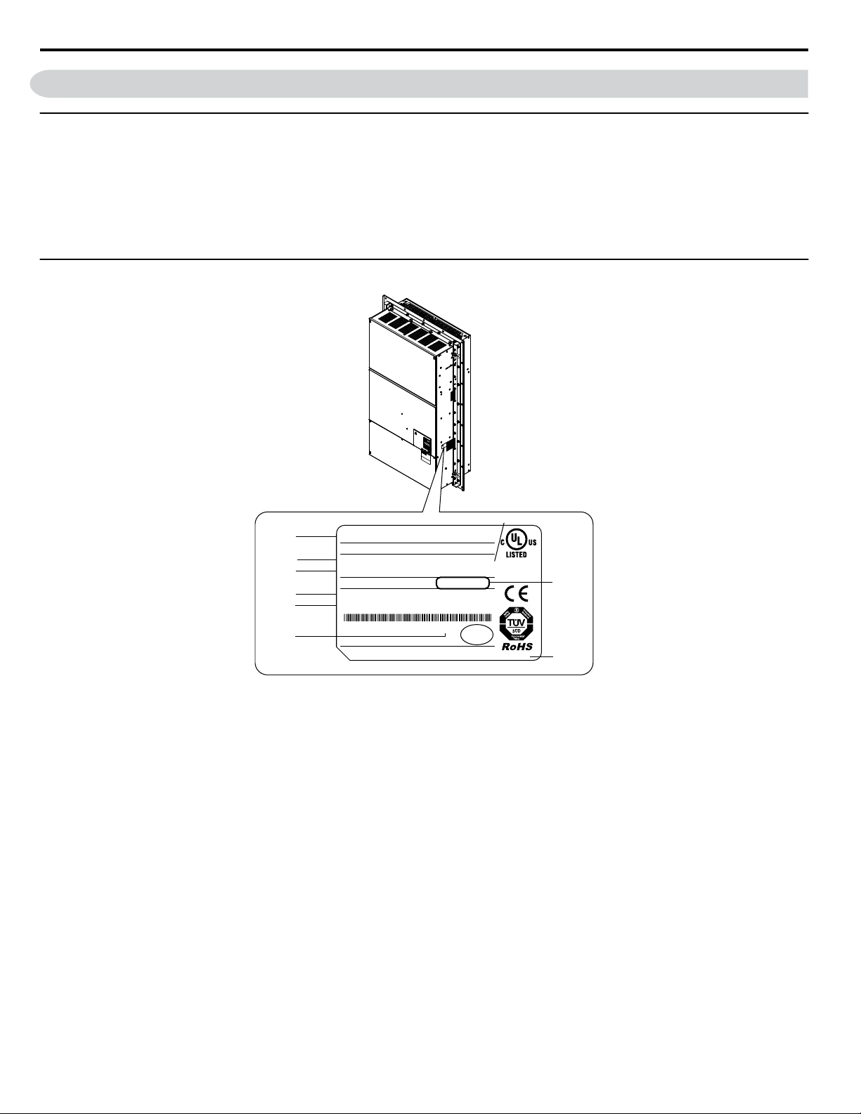
Model Number and Nameplate Check
Please perform the following tasks after receiving the drive:
• Inspect the drive for damage.
If the drive appears damaged upon receipt, contact the shipper immediately.
• Verify receipt of the correct model by checking the information on the nameplate.
• If you have received the wrong model or the drive does not function properly, contact your supplier.
u
Nameplate
A – Normal Duty / Heavy Duty Amps
B – Software version
C –
Address
<1>
D – Enclosure type
F – Lot number
G – Output specifications
H – Input specifications
I – AC drive model
E – Serial number
Figure 1 Nameplate Information Example
<1> The address of the head office of Yaskawa Electric Corporation (responsible for product liability) is shown on the nameplate.
10
YASKAWA TOEP YAIA1U 02A YASKAWA AC Drive – A1000 6-Phase/12-Pulse Input Installation Manual
Page 11

CIMR
-
A U 4 T
0675 U
A A
Drive
A1000
Series
Letter
Enclosure
Type
Design
Revision
Order
Letter
Region
Code
USA
No. Voltage Class
Letter
Environmental
Specification
A Standard
380-480 Vac 4
Customized
Specification
6-Phase/
12-Pulse Input
<2>
A
Refer to the tables below
Flange Type
U
<1>
U
Open Type
(Non-Flange)
1 Receiving
<1> Provides method of mounting drive with backside (heatsink) external to enclosure with NEMA 12 integrity.
<2> Drives with these specifications do not guarantee complete protection for the environmental conditions indicated.
6-Phase/12-Pulse 400 V Class Rated Output
n
Table 1 Model Number and Specifications (400 V Class)
Drive Model
4T0058o
4T0072o
4T0088o
4T0103o
4T0139o
4T0165o
4T0208o
4T0250o
4T0296o
4T0362o
4T0414o
4T0515o
4T0675o
Normal Duty (ND)
C6-01 = 1
Max. Motor Capacity
kW (HP)
30 (40) 58
37 (50) 72
45 (60) 88
55 (75) 103
75 (100) 139
90 (125) 165
110 (150) 208
132 (200) 250
160 (250) 296
185 (300) 362
220 (350) 414
250 (400-450) 515
355 (500-550) 675
Rated Output
Current A
Drive Model
4T0058o
4T0072o
4T0088o
4T0103o
4T0139o
4T0165o
4T0208o
4T0250o
4T0296o
4T0362o
4T0414o
4T0515o
4T0675o
Heavy Duty (HD)
C6-01 = 0
Max. Motor Capacity
kW (HP)
22 (25-30) 45
30 (40) 60
37 (50-60) 75
45 (50-60) 91
55 (75) 112
75 (100) 150
90 (125-150) 180
110 (150) 216
132 (200) 260
160 (250) 304
185 (300) 370
220 (350) 450
315
(400-450-500)
Rated Output
Current A
605
YASKAWA TOEP YAIA1U 02A YASKAWA AC Drive – A1000 6-Phase/12-Pulse Input Installation Manual
11
Page 12
A
B
C
D
D
1 Receiving
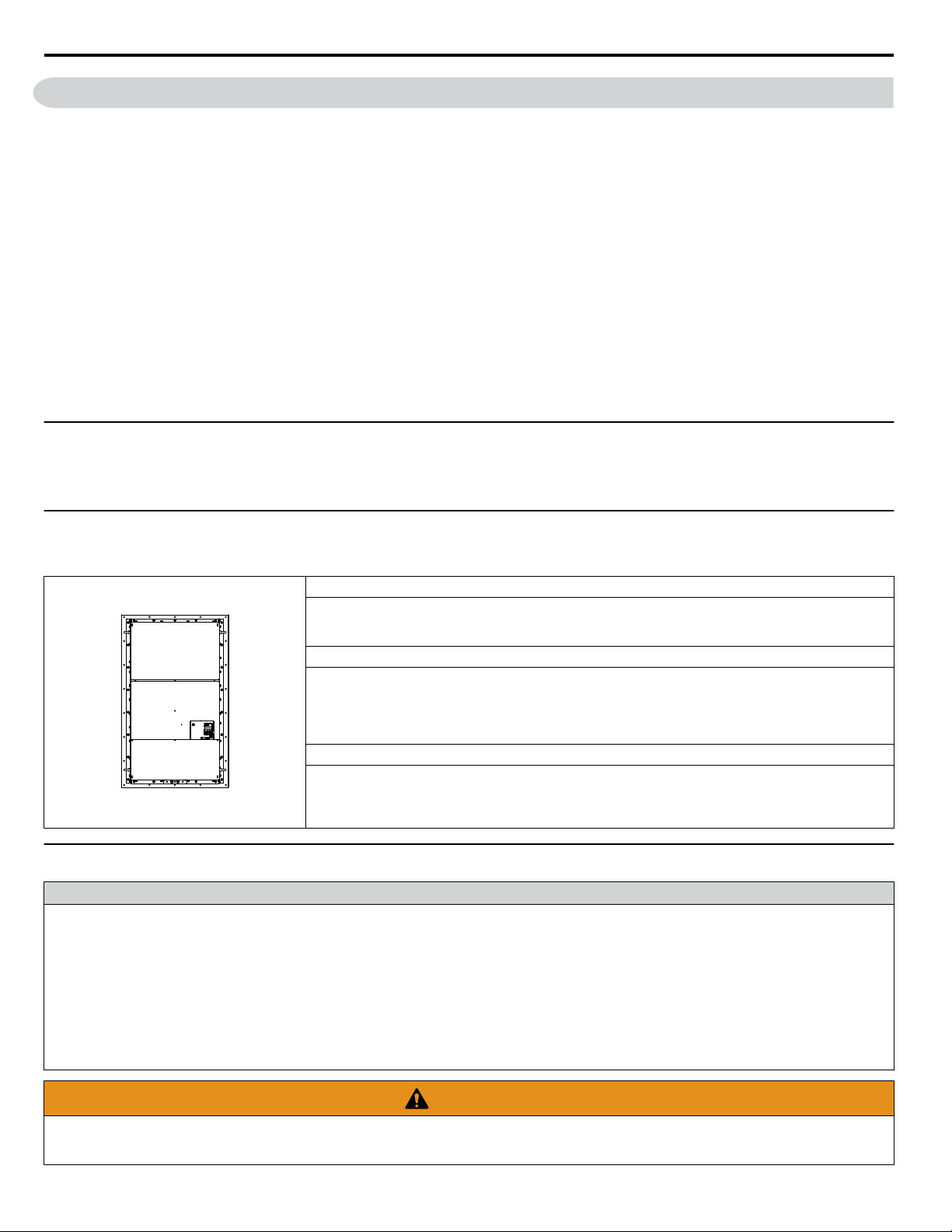
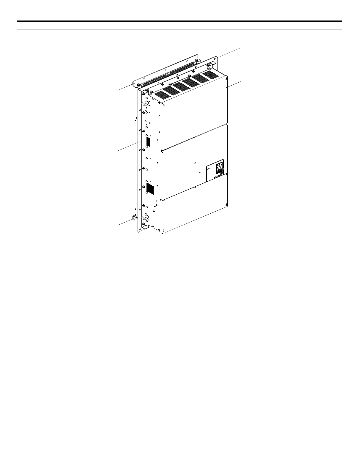
u
6-Phase/12-Pulse Component Names
A – Installation hole
B – 6-Phase/12-Pulse Drive
Figure 2 Flange Type Enclosure Example (Models 4TooooU)
<1> Provides method of mounting drive with backside (heatsink) external to enclosure with NEMA 12 integrity. 4TooooU models
only.
NOTICE: Remove the shipping package attachments before installing. The shipping package attachments will interfere with the cutting of
the panel when installing the drive.
C –
Mounting flange
D – Shipping package attachment (to
be removed before installation)
<1>
12
YASKAWA TOEP YAIA1U 02A YASKAWA AC Drive – A1000 6-Phase/12-Pulse Input Installation Manual
Page 13

2 Mechanical Installation
2 Mechanical Installation
This section outlines specifications, procedures, and the environment for proper mechanical installation of the drive.
u
Installation Environment
Install the drive in an environment matching the specifications in Table 2 to help prolong the optimum performance life of
the drive.
Table 2 Installation Environment
Environment Conditions
Installation Area Indoors
Flange Type Enclosure: -10 °C to +40 °C (14 °F to 104 °F)
Non-Flange Type Enclosure: -10 °C to +50 °C (14 °F to 122 °F)
Ambient Temperature
Humidity 95% RH or less and free of condensation
Storage Temperature -20 °C to +60 °C
Surrounding Area
Altitude Up to 1000 m without derating, up to 3000 m with output current and voltage derating.
Vibration
Orientation Install the drive vertically to maintain maximum cooling effects.
Drive reliability improves in environments without wide temperature fluctuations.
When using the drive in an enclosure panel, install a cooling fan or air conditioner in the area to ensure that the air
temperature inside the enclosure does not exceed the specified levels.
Do not allow ice to develop on the drive.
Install the drive in an area free from:
• oil mist and dust
• metal shavings, oil, water, or other foreign materials
• radioactive materials
• combustible materials (e.g., wood)
• harmful gases and liquids
• excessive vibration
• chlorides
• direct sunlight.
10 Hz to 20 Hz at 9.8 m/s
20 Hz to 55 Hz at 5.9 m/s2 (Models 4T0058o to 4T0165o) or 2.0 m/s2 (Models 4T0208o to 4T0675o)
2
NOTICE: Avoid placing drive peripheral devices, transformers, or other electronics near the drive as the noise created can lead to erroneous
operation. If such devices must be used in close proximity to the drive, take proper steps to shield the drive from noise.
NOTICE: Damage to Equipment. Drive heatsink air outlet temperature may be over 80 °C. Do not install components above the air outlet
that may be damaged by 80 °C air temperature.
NOTICE: Damage to Equipment. Prevent foreign matter such as metal shavings and wire clippings from falling into the drive during
installation. Failure to comply could result in damage to the drive. Place a temporary cover over the top of the drive during installation.
Remove the temporary cover before drive start-up, as the cover will reduce ventilation and cause the drive to overheat.
YASKAWA TOEP YAIA1U 02A YASKAWA AC Drive – A1000 6-Phase/12-Pulse Input Installation Manual
13
Page 14
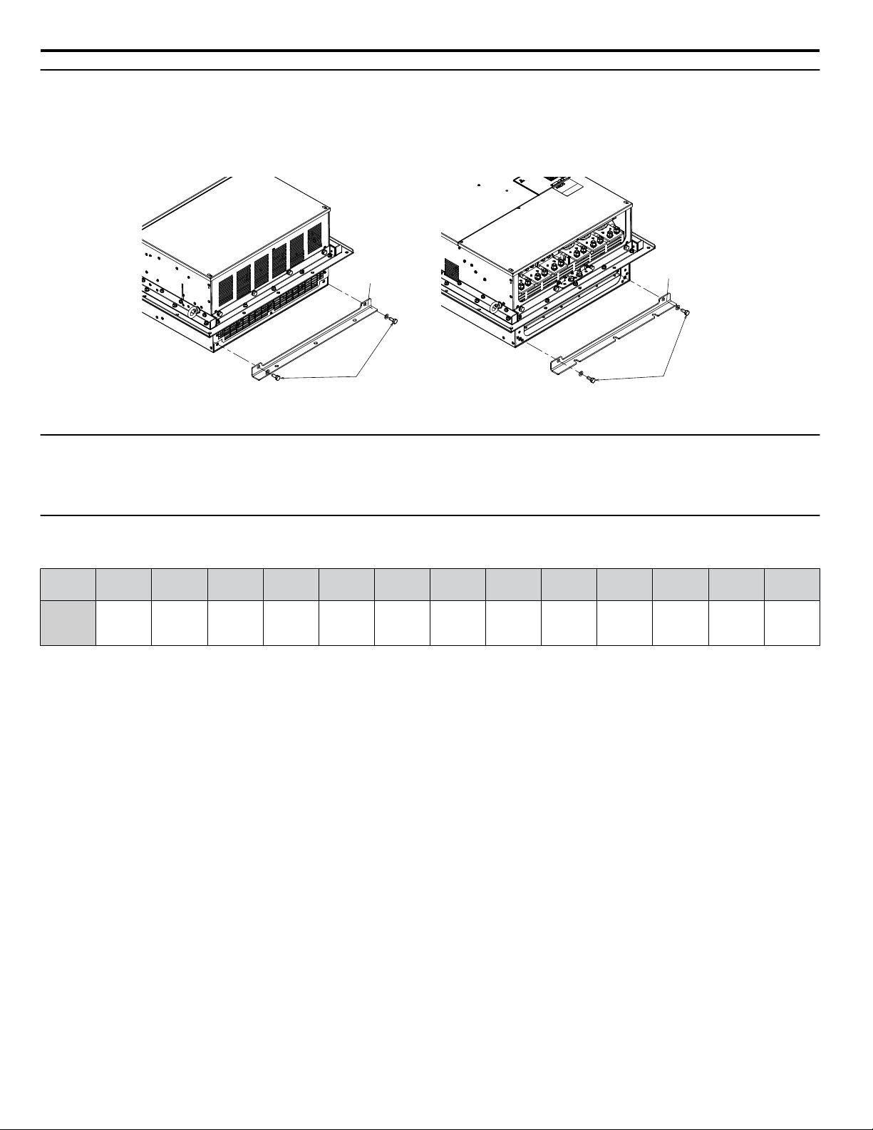
Screws
Shipping Package
Attachment
Shipping Package
Attachment
Top Side
Screws
Bottom Side
2 Mechanical Installation
u
Removing the Shipping Package Attachments
Remove the shipping package attachments before installation.
Note: The number of screws varies in accordance with the drive model.
Figure 3 Removing the Shipping Package Attachments
u
Exterior and Mounting Dimensions
Refer to External Mounting and Panel Cutout Dimensions on page 44 for 6-phase/12-pulse exterior and mounting
dimensions.
u
Weights
Table 3 Drive Weights
Drive
Model
Drive
Weight
kg (lb)
4T0058o 4T0072o 4T0088o 4T0103o 4T0139o 4T0165o 4T0208o 4T0250o 4T0296o 4T0362o 4T0414o 4T0515o 4T0675o
21 (46.2) 24 (52.8) 35 (77.0) 35 (77.0) 39 (85.8) 40 (88.2) 78 (172) 90 (198) 95 (209) 97 (214) 127 (280) 210 (463) 215 (474)
14
YASKAWA TOEP YAIA1U 02A YASKAWA AC Drive – A1000 6-Phase/12-Pulse Input Installation Manual
Page 15

3 Electrical Installation
3 Electrical Installation
u
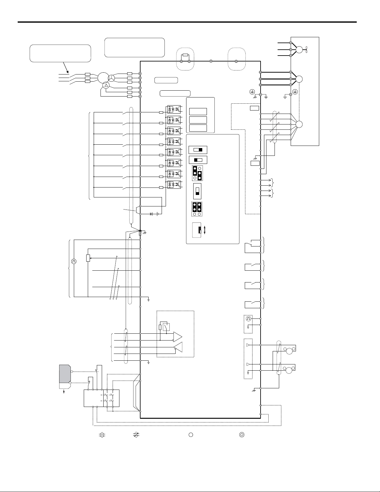
Standard Connection Diagram
Connect the drive and peripheral devices as shown in Figure 4. It is possible to set and run the drive via the digital operator
without connecting digital I/O wiring.
WARNING! Fire Hazard - Drive Short-Circuit Current Rating. Install adequate branch circuit protection according to applicable local codes
and this manual. Failure to comply could result in fire and damage to the drive or injury to personnel. The device is suitable for use on a
circuit capable of delivering not more than 100,000 RMS symmetrical amperes, 480 Vac maximum (400 V class), when protected by branch
circuit protection devices specified in this manual.
NOTICE: Route motor leads U/T1, V/T2, and W/T3 separate from all other leads to reduce possible interference related issues. Failure to
comply may result in abnormal operation of drive and nearby equipment.
NOTICE: Equipment Hazard. Standard motors used with PWM drives may experience winding failures due to surge voltages when input
line voltage is greater than 480 V or motor wire distance is greater than 100 meters. Select a motor design with insulation tolerant of surge
voltages, such as drive-rated motor for use with PWM drives. Failure to comply could lead to motor winding failure.
Note: The minimum load for the relay outputs M1-M2, M3-M4, M5-M6, and MA-MB-MC is 10 mA.
YASKAWA TOEP YAIA1U 02A YASKAWA AC Drive – A1000 6-Phase/12-Pulse Input Installation Manual
15
Page 16
+
-
+
-
+
+
-
+
-
+
+
-
S1
S2
S3
S4
S5
S6
S7
MP
DM
DM
RP
A1
A2
A3
0 V
AC
R
R
S
S-
IG
H1
H2
HC
Drive
2 k
S8
SC
0 V
0 V
AC
FM
AM
AC
E (G)
S1
S2
<11>
<6>
<12>
<13>
<8>
<10>
<6>
<4>
<3>
+24 V
+V
MA
M1
M2
MB
MC
Forward Run / Stop
Reverse Run / Stop
External fault
Fault reset
Multi-speed step 1
Multi-speed step 2
External Baseblock
Jog speed
Multi-function
digtial inputs
(default setting)
Sink / Source mode
selection wire link
(default: Sink)
CN5-C
CN5-B
CN5-A
Option board
Pulse Train Input
(max 32 kHz)
Shield ground
terminal
Multi-function
analog/pulse
train inputs
Power supply +10.5 Vdc, max. 20 mA
Analog Input 1 (Frequency Reference Bias)
-10 to +10 Vdc (20 k )
Analog Input 2 (Frequency Reference Bias)
-10 to +10 Vdc (20 k )
0 or 4 to 20 mA (250 )
Analog Input 3 / PTC Input (Aux. frequency
reference)
-10 to +10 Vdc (20 k )
-V
Power supply, -10.5 Vdc, max. 20 mA
Safety
switch
MEMOBUS/Modbus comm.
RS-422/RS-485
max. 115.2 kBps
Safe Disable inputs
Wire
jumper
Open
Safety relay /
controller
Termination resistor
(120 , 1/2 W)
DIP
Switch S2
Fault relay output
250 Vac, max. 1 A
30 Vdc, max 1 A
(min. 5 Vdc, 10 mA)
Multi-function relay output (During Run)
250 Vac, max. 1 A
30 Vdc, max 1 A
(min. 5 Vdc, 10 mA)
Multi-function pulse train output
(Output frequency)
0 to 32 kHz (2.2 k )
Multi-function analog output 1
(Output frequency)
-10 to +10 Vdc (2mA)
or 4 to 20 mA
EDM (Safety Electronic Device Monitor)
Control Circuit
shielded line
twisted-pair shielded line
main circuit terminal
control circuit terminal
M3
M4
Multi-function relay output (Zero Speed)
250 Vac, max. 1 A
30 Vdc, max 1 A
(min. 5 Vdc, 10 mA)
M5
M6
Multi-function relay output (Speed Agree 1)
250 Vac, max. 1 A
30 Vdc, max 1 A
(min. 5 Vdc, 10 mA)
SP
SN
<9>
AMFM
V
I
V
I
DIP Switch S1
A2 Volt/Curr. Sel
DIP Switch S4
A3 Analog/PTC
Input Sel
PTC
AI
Off
On
DIP Switch S2
Term. Res. On/Off
Jumper S3
H1, H2
Sink/Source Sel.
Jumper S5
AM/FM Volt./Curr.
Selection
Terminal board
jumpers and switches
FM
+
-
AM
<5>
<14>
Ω
Ω
Ω
Ω
Ω
Ω
<13>
Multi-function analog output 2
(Output current)
-10 to +10 Vdc (2mA)
or 4 to 20 mA
<15>
<6>
A+
A-
B-
Z-
B+
Z+
a+
ab+
bz+
z-
FE
IP
IG
TB1
SD
TB2
B track monitor
A track monitor
M
U/T1
V/T2
W/T
U
FU
FV
FW
V
W
3
Ground
Cooling fan
PG
M
PG- X3
connectors
(option)
Ω
Slide Switch S6
DM+, DMN.C./N.O. Selection
N.C.
N.O.
<7>
Terminals B1, B2, -, and +3, B1
are for power option connections.
Never connect power supply lines
to these terminals
B1 B2
Fuse
Main Circuit
Three-Phase
Power Supply
380 to 480 V
50/60 Hz
Wiring sequence should shut off
power to the drive when a fault
output is triggered.
BCP
R/L1
S/L2
T/L3
R1/L11
S1/L21
T1/L31
R
S
T
Main
Switch
Models 4T0058 and 4T0072
Dynamic braking resistor
(option) <1> <2>
U1
V1
W1
W2
V2
U2
-
+3
Models 4T0088 to 4T0675
CDBR dynamic braking unit
(option) <1> <2>
<16>
<17>
3 Electrical Installation
Figure 4 Drive Standard Connection Diagram
16
YASKAWA TOEP YAIA1U 02A YASKAWA AC Drive – A1000 6-Phase/12-Pulse Input Installation Manual
Page 17

3 Electrical Installation
<1> Set up a thermal relay sequence to disconnect drive main power in the event of an overheat condition on the dynamic
braking option.
<2> Set L8-55 to 0 to disable the protection function of the built-in braking transistor of the drive when using an optional
regenerative converter or dynamic braking option. Leaving L8-55 enabled may cause a braking resistor fault (rF). Additionally,
disable Stall Prevention (L3-04 = 0) when using an optional regenerative converter, regenerative or braking units, or dynamic
braking option. Leaving If L3-04 enabled may prevent the drive from stopping within the specified deceleration time.
<3> Supplying power to the control circuit separately from the main circuit requires 24 V power supply (option).
<4> This figure illustrates an example of a sequence input to S1 through S8 using a non-powered relay or an NPN transistor.
Install the wire link between terminals SC-SP for Sink mode, between SC-SN for Source mode, or leave the link out for
external power supply. Never short terminals SP and SN, as it will damage the drive.
<5> This voltage source supplies a maximum current of 150 mA when not using a digital input card DI-A3.
<6> The maximum output current capacity for the +V and -V terminals on the control circuit is 20 mA. Never short terminals
+V, -V, and AC, as it can cause erroneous operation or damage the drive.
<7> Slide switch S6 selects N.C. or N.O. as the state of the DM+ and DM- terminals for EDM output. Slide switch S6 is
available on terminal board ETC74030o.
<8> Set DIP switch S1 to select between a voltage or current input signal to terminal A2. The default setting is for current
input.
<9> Set DIP switch S4 to select between analog or PTC input for terminal A3.
<10> Set DIP switch S2 to the ON position to enable the termination resistor in the last drive in a MEMOBUS/Modbus network.
<11> Use jumper S3 to select between Sink mode, Source mode, and external power supply for the Safe Disable inputs.
<12> Disconnect the wire jumper between H1 - HC and H2 - HC when utilizing the Safe Disable input.
<13> Monitor outputs work with devices such as analog frequency meters, ammeters, voltmeters, and wattmeters. They are
not intended for use as a feedback-type signal.
<14> Use jumper S5 to select between voltage or current output signals at terminals AM and FM. Set parameters H4-07 and
H4-08 accordingly.
<15> Self-cooling motors do not require the same wiring necessary for motors with cooling fans.
<16> Refer to local codes for proper branch circuit protection (BCP) on the primary side of the 6-Phase/12-Pulse transformer.
<17> Fuse selection for the secondary side is of the 6-Phase/12-Pulse transformer is shown in Table 13 and Table 14.
WARNING! Sudden Movement Hazard. Do not close the wiring for the control circuit unless the multifunction input terminal parameters are
properly set. Improper sequencing of run/stop circuitry could result in death or serious injury from moving equipment.
WARNING! Sudden Movement Hazard. Ensure start/stop and safety circuits are wired properly and in the correct state before energizing
the drive. Failure to comply could result in death or serious injury from moving equipment. When programmed for 3-Wire control, a momentary
closure on terminal S1 may cause the drive to start.
WARNING! Sudden Movement Hazard. When using a 3-Wire sequence, set the drive to 3-Wire sequence prior to wiring the control terminals
and set parameter b1-17 to 0 so the drive will not accept a Run command at power up (default). If the drive is wired for a 3-Wire sequence
but set up for a 2-Wire sequence (default), and parameter b1-17 is set to 1 so the drive accepts a Run command at power up, the motor
will rotate in reverse direction at drive power up and may cause injury.
WARNING! Sudden Movement Hazard. Confirm the drive I/O signals and external sequence before executing the application preset
function. Executing the application preset function or setting A1-06 ≠ 0 will change the drive I/O terminal functions and may cause unexpected
equipment operation. Failure to comply may cause death or serious injury.
NOTICE: When using the automatic fault restart function with wiring designed to shut off the power supply upon drive fault, make sure the
drive does not trigger a fault output during fault restart (L5-02 = 0, default). Failure to comply will prevent the automatic fault restart function
from working properly.
YASKAWA TOEP YAIA1U 02A YASKAWA AC Drive – A1000 6-Phase/12-Pulse Input Installation Manual
17
Page 18
R1/L11
S1/L21
T1/L31
Gate
Board
Control
Board
Operator
B1
R/L1
S/L2
T/L3
–
U/T1
V/T2
W/T3
Relay
Current
Sensor
B2
Gate
Board
Control
Board
Operator
+3
R/L1
S/L2
T/L3
R1/L11
S1/L21
T1/L31
–
U/T1
V/T2
W/T3
Relay
Current
Sensor
3 Electrical Installation
u
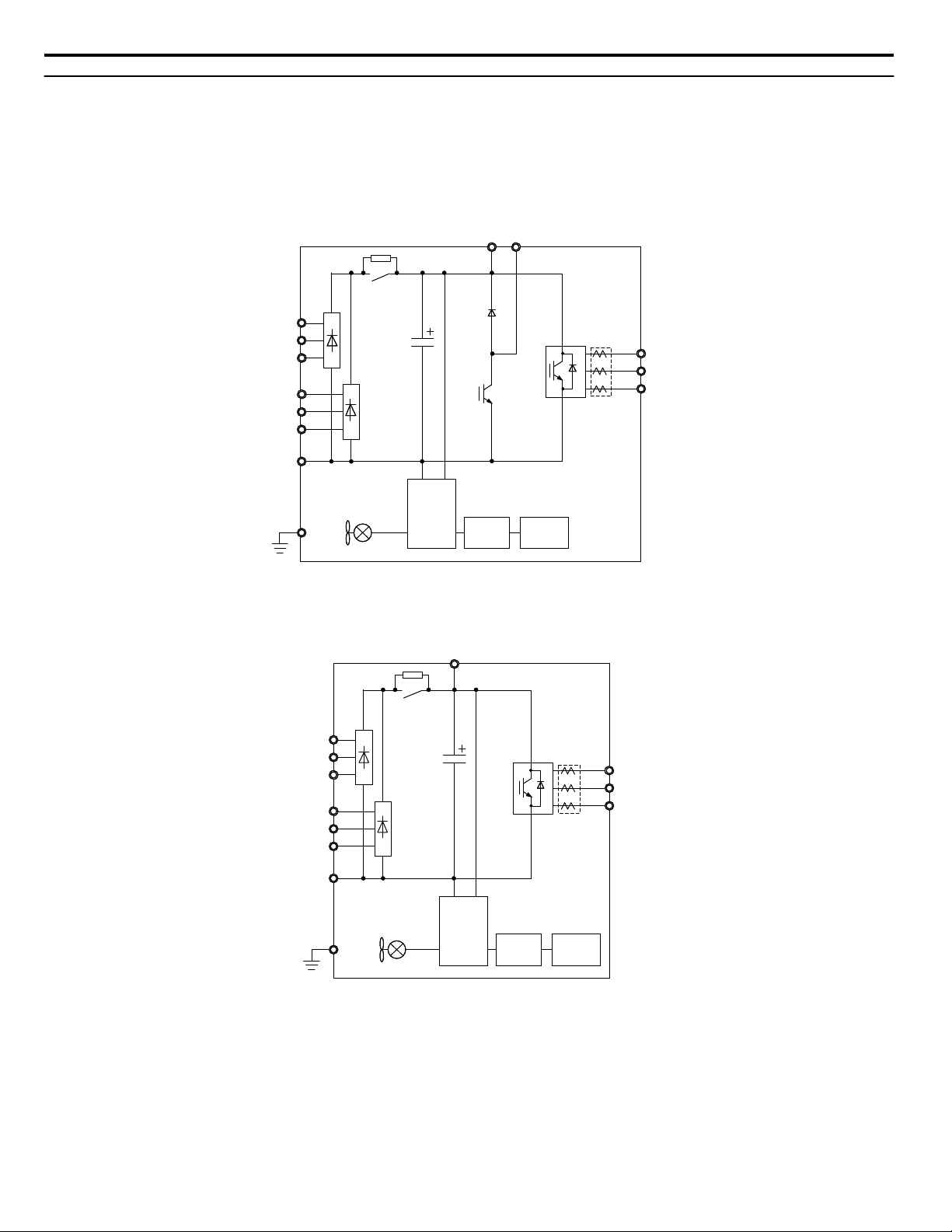
Main Circuit Connection Diagram
Refer to Figure 5, Figure 6, and Figure 7 when wiring the main circuit of the drive. Connections may vary based on drive
capacity.
NOTICE: Do not use the negative DC bus terminal “⊖” as a ground terminal. This terminal is at high DC voltage potential. Improper wiring
connections could damage the drive.
6-Phase/12-Pulse Input 400 V Class Models 4T0058o and 4T0072o
n
Figure 5 Connecting Main Circuit Terminals
6-Phase/12-Pulse Input 400 V Class Models 4T0088o to 4T0139o
n
Figure 6 Connecting Main Circuit Terminals
18
YASKAWA TOEP YAIA1U 02A YASKAWA AC Drive – A1000 6-Phase/12-Pulse Input Installation Manual
Page 19
Gate
Board
Control
Board
Operator
24 V
Power
Supply
+3
R/L1
S/L2
T/L3
R1/L11
S1/L21
T1/L31
ー
U/T1
V/T2
W/T3
Relay
Current
Sensor
+
U/T1
V/T2
W/T3
R/L1
S/L2
T/L3
R1/L11
S1/L21
T1/L31
CDBR dynamic braking unit
(option) <2>
Dynamic braking resistor
(option) <1>
Motor
+3
-
Main Circuit
Power Supply
6-Phase/12-Pulse
Isolation Transformer
3-Phase Line Monitor
FuseBCP
Fuse
<3>
<4>
3 Electrical Installation
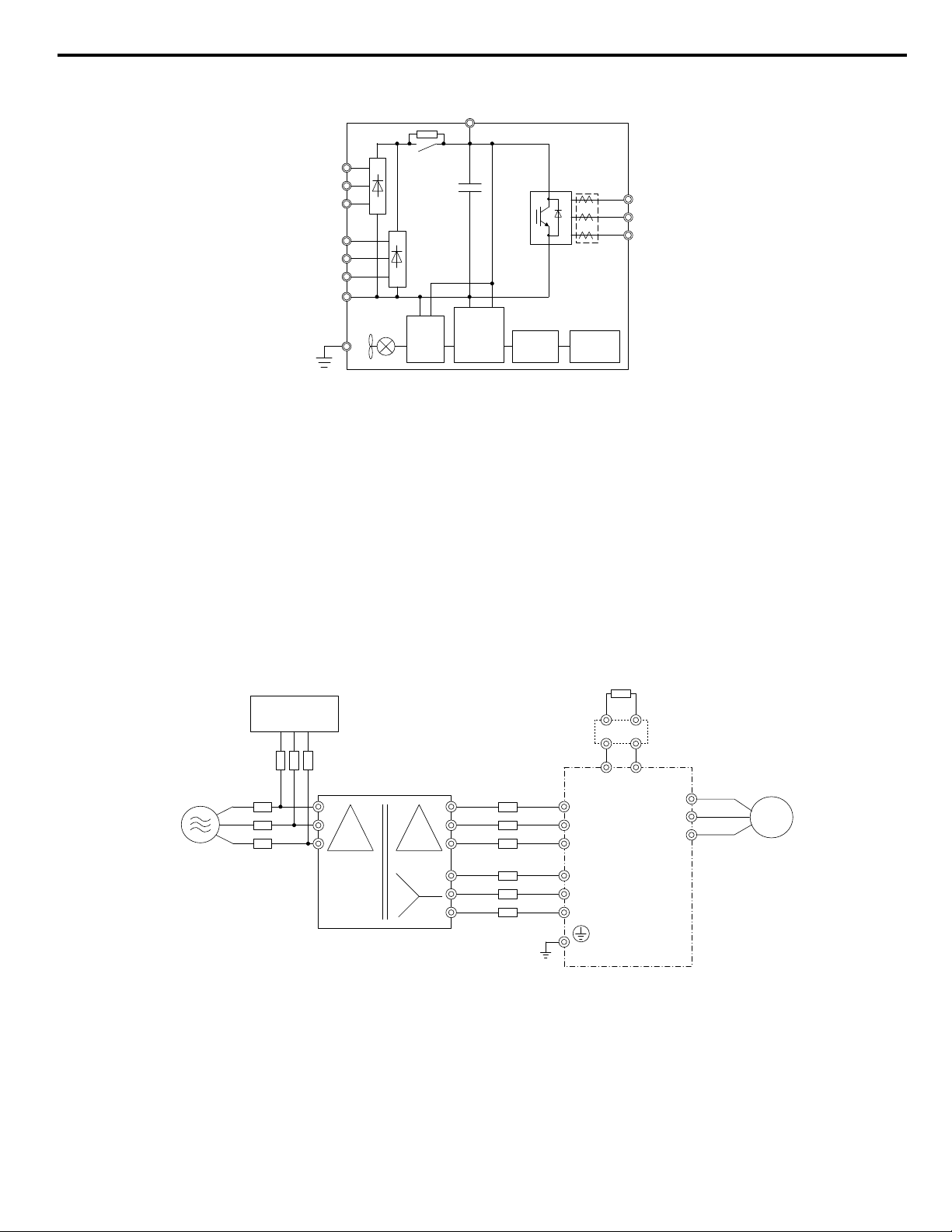
6-Phase/12-Pulse Input 400 V Class Models 4T0165o to 4T0675o
n
Figure 7 Connecting Main Circuit Terminals
6-Phase/12-Pulse Rectification
n
Installing a Transformer
Install a 6-Phase/12-Pulse isolation transformer with output windings phase-shifted by 30 electrical degrees or install a Hybrid
6-Phase topology on the power supply.
Installing a 3-Phase Line Monitor
Yaskawa requires installation of a 3-Phase line monitor to protect the drive in the event of an input line phase loss.
The 3-Phase line monitor must be installed on the primary circuit of the 6-Phase/12-Pulse transformer and connected to the
drive to remove the Run command when a phase loss condition occurs.
The drive power circuit may be damaged during a phase-loss condition if a 3-Phase line monitor is not properly installed.
Contact a Yaskawa representative for help selecting the optimum 3-Phase line monitor and fuses.
Connection Diagram
Figure 8 Main Circuit Terminal Connections
<1> A dynamic braking resistor can be connected to the B1 and B2 terminals on models 4T0058o and 4T0072o.
<2> A CDBR dynamic braking unit cannot be connected to models 4T0058o or 4T0072o.
<3> Refer to local codes for proper branch circuit protection (BCP) on the primary side of the 6-Phase/12-Pulse transformer.
<4> Fuse selection for the secondary side is of the 6-Phase/12-Pulse transformer is shown in Table 13 and Table 14
YASKAWA TOEP YAIA1U 02A YASKAWA AC Drive – A1000 6-Phase/12-Pulse Input Installation Manual
19
Page 20
S1/L21
R1/L11
T1/L31
T/L3
U/T1
R/L1
S/L2
V/T2
W/T3
B1 B2
3
R/L1 S/L2 T/L3 R1/L11 S1/L21 T1/L31 U/T1 V/T2 W/T3
R/L1
S/L2
T/L3
R1/L11
U/T1 W/T3V/T2
S1/L21
T1/L31
3
3 Electrical Installation
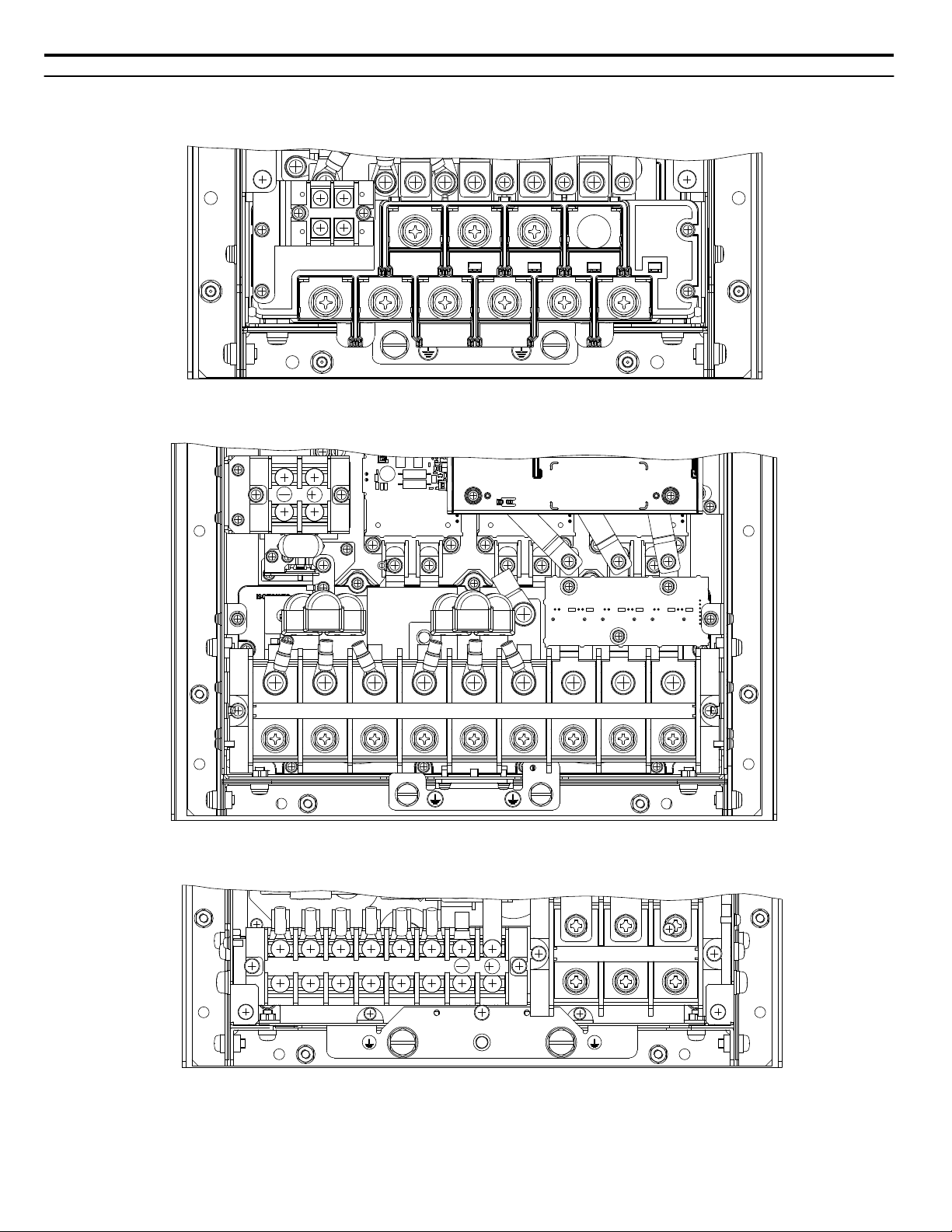
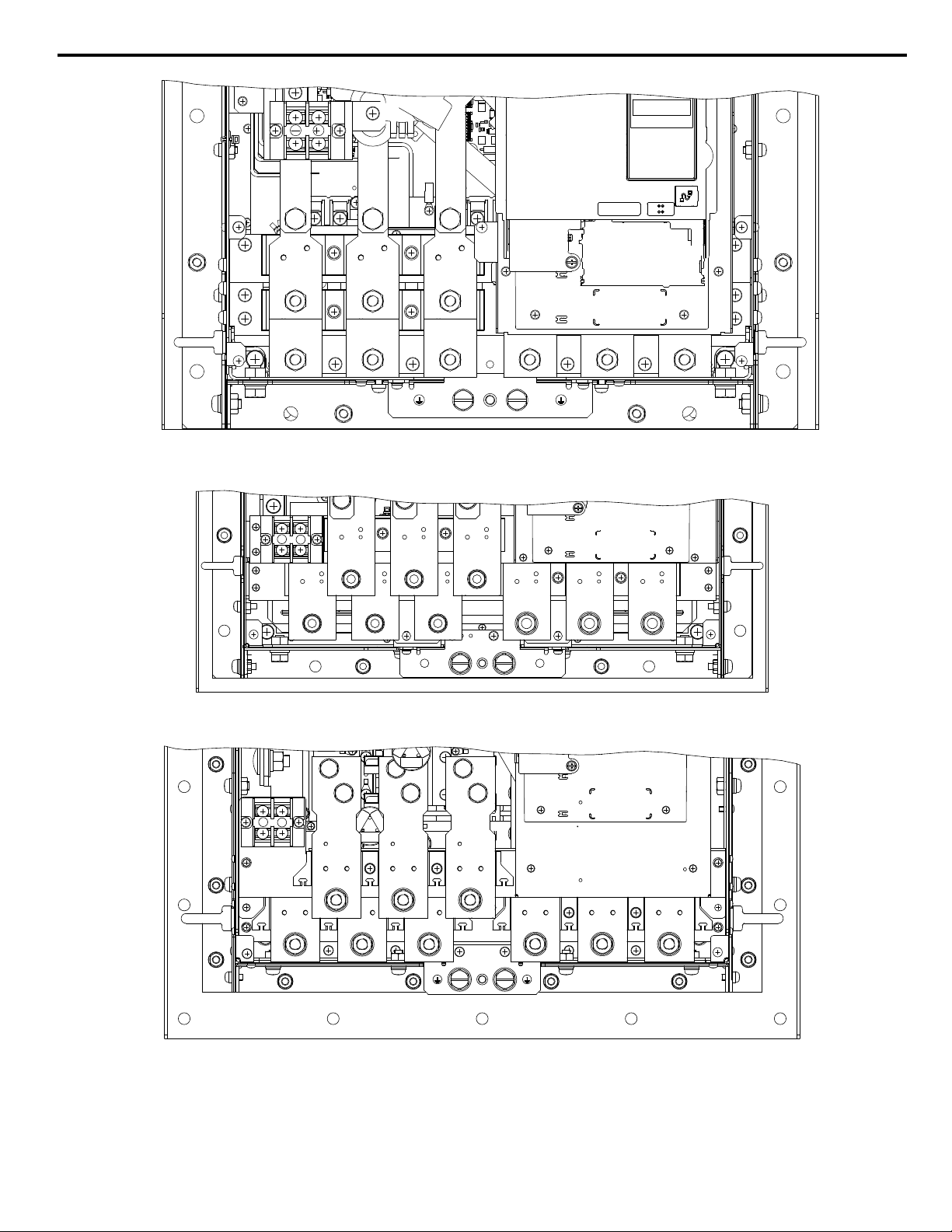
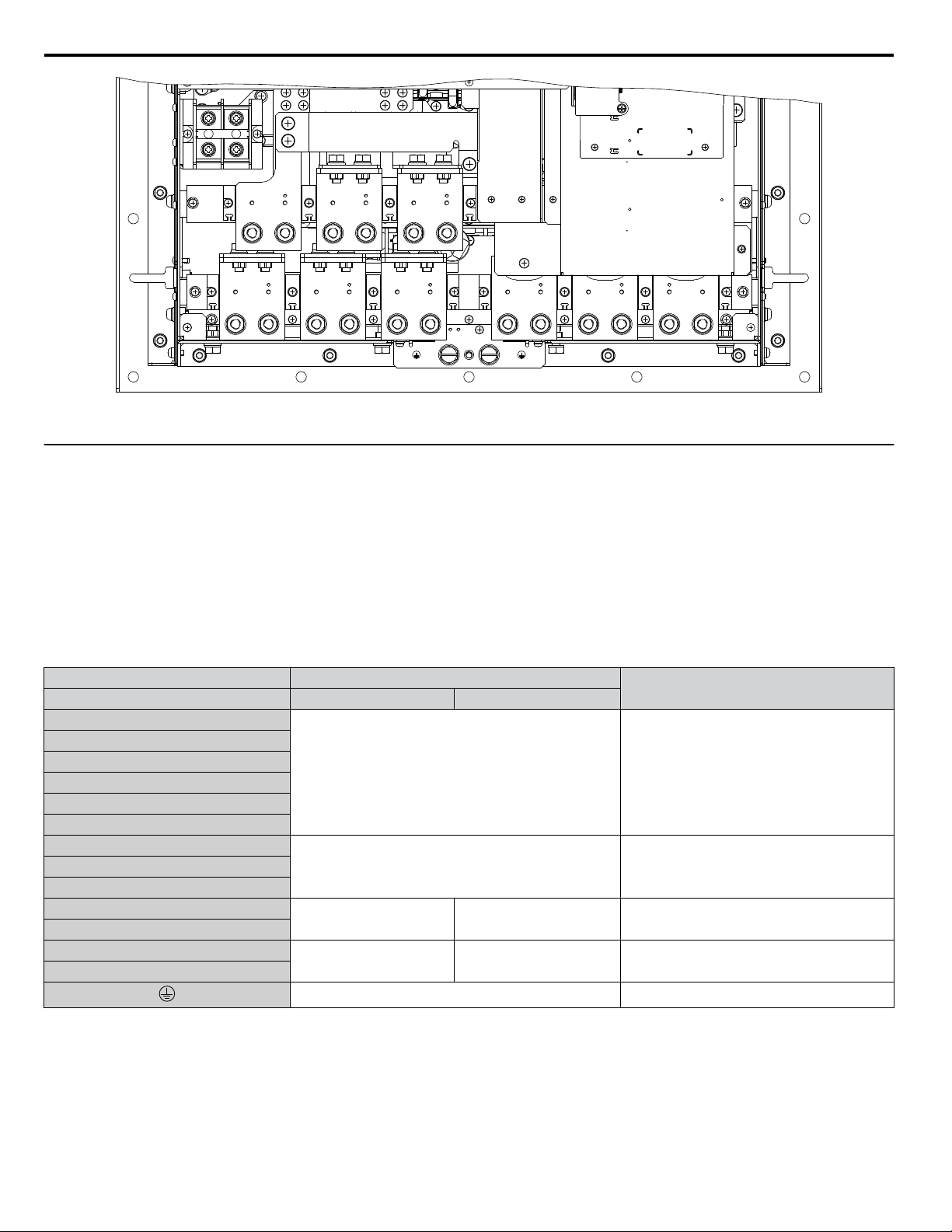
u
Terminal Specifications
Figure 9 to Figure 15 show the different terminal arrangements for the drive capacities.
Figure 9 Model 4T0058o and 4T0072o Terminals
20
Figure 10 Models 4T0088o and 4T0103o Terminals
Figure 11 Models 4T0139o and 4T0165o Terminals
YASKAWA TOEP YAIA1U 02A YASKAWA AC Drive – A1000 6-Phase/12-Pulse Input Installation Manual
Page 21
R1/L11
S1/L21
T1/L31
R/L1
S/L2
T/L3
U/T1
V/T2
W/T3
3
Figure 12 Model 4T0208o Terminals
R1/L11
S1/L21
T1/L31
R/L1
S/L2
T/L3
U/T1
V/T2
W/T3
+3
-
R1/L11
S1/L21
T1/L31
R/L1
S/L2
T/L3
U/T1
V/T2
W/T3
+3
-
3 Electrical Installation
Figure 13 Models 4T0250o to 4T0362o Terminals
Figure 14 Model 4T0414o Terminals
YASKAWA TOEP YAIA1U 02A YASKAWA AC Drive – A1000 6-Phase/12-Pulse Input Installation Manual
21
Page 22
R1/L11
S1/L21
T1/L31
R/L1
S/L2
T/L3
U/T1
V/T2
W/T3
+3
-
3 Electrical Installation
Figure 15 Models 4T0515o and 4T0675o Terminals
u
Main Circuit Wiring
This section describes the functions, specifications, and procedures required to safely and properly wire the main circuit in
the drive.
NOTICE: Do not solder the ends of wire connections to the drive. Soldered wiring connections can loosen over time. Improper wiring practices
could result in drive malfunction due to loose terminal connections.
NOTICE: Do not switch the drive input to start or stop the motor. Frequently switching the drive on and off shortens the life of the DC bus
charge circuit and the DC bus capacitors, and can cause premature drive failures. For the full performance life, refrain from switching the
drive on and off more than once every 30 minutes.
Main Circuit Terminal Functions
n
Table 4 Main Circuit Terminal Functions
Terminal Type
Model
R/L1
S/L2
T/L3
R1/L11
S1/L21
T1/L31
U/T1
W/T3
B1
B2
⊖
⊕3
Note: Note: DC power supply input is not available for 6-Phase/12-Pulse Input models.
Main Circuit Fuses
n
4T0058o and 4T0072o 4T0088o to 4T0675o
Main circuit power supply input Not available Connects line power to the drive
Drive output Connects to the motorV/T2
Braking resistor Not available
Not available
10 Ω or less Grounding terminal
Braking unit connection
(⊕3 and ⊖)
Available for connecting a braking resistor or a
braking resistor unit option
Only for connecting dynamic braking options
Function
The 6-Phase/12-Pulse drive requires fuses to be installed on each of the 6 input phases between the 6-Phase/12- Pulse
transformer and the drive. Select fuses from Table 13 or Table 14 according to drive model to maintain standards compliance.
22
YASKAWA TOEP YAIA1U 02A YASKAWA AC Drive – A1000 6-Phase/12-Pulse Input Installation Manual
Page 23

3 Electrical Installation
u
Wire Gauges and Tightening Torques
Use the tables in this section to select the appropriate wires and crimp terminals.
Gauges listed in the tables are for use in the United States.
Note: 1. Wire gauge recommendations based on drive continuous current ratings (ND) using 75 °C 600 Vac vinyl-sheathed wire assuming ambient
temperature within 40 °C and wiring distance shorter than 100 m.
2. Terminals ⊕3 and ⊖ are for connecting optional power devices. Use caution to connect only approved devices to the correct terminal(s).
• Consider the amount of voltage drop when selecting wire gauges. Increase the wire gauge when the voltage drop is greater
than 2% of motor rated voltage. Ensure the wire gauge is suitable for the terminal block. Use the following formula to
calculate the amount of voltage drop:
Line drop voltage (V) = 3 × wire resistance (Ω/km) × wire length (m) × current (A) × 10
-3
• Refer to CDBR manual TOBP C720600 00/TOBP C720600 01 for dynamic braking wire gauges.
• Use terminals ⊕3 and ⊖ when connecting a CDBR dynamic braking unit.
• Do not connect a regenerative converter or a regenerative unit to the 6-Phase/12-Pulse drive.
• Refer to UL Standards on page 84 for information on UL compliance.
Yaskawa recommends using closed-loop crimp terminals on all drive models. UL/cUL approval requires the use of closedloop crimp terminals when wiring the drive main circuit terminals. Use only the tools recommended by the terminal
manufacturer for crimping. Refer to Closed-Loop Crimp Terminal Size on page 86 for closed-loop crimp terminal
recommendations.
The wire gauges listed in Table 5 are Yaskawa recommendations and are based on the 6-Phase input current ratings specified
in Table 14. Refer to local codes for proper wire gauge selections.
Drive Model
4T0058o
4T0072o
4T0088o
4T0103o
4T0139o
4T0165o
4T0208o
Table 5 Wire Gauge and Torque Specifications
Terminal
R/L1, S/L2, T/L3
R1/L11, S1/L21, T1/L31
U/T1, V/T2, W/T3
B1, B2 22 to 10 (0.3 to 5.3) M4 1.2 (10.6)
Refer to applicable codes for wire size M8
R/L1, S/L2, T/L3
R1/L11, S1/L21, T1/L31
U/T1, V/T2, W/T3
B1, B2 22 to 10 (0.3 to 5.3) M4 1.2 (10.6)
Refer to applicable codes for wire size M8
R/L1, S/L2, T/L3
U/T1, V/T2, W/T3
⊖, ⊕3
Refer to applicable codes for wire size M8 9 to 11 (79.7 to 97.4)
R/L1, S/L2, T/L3
R1/L11, S1/L21, T1/L31
⊖, ⊕3
U/T1, V/T2, W/T3 6 to 250 (13.3 to 127) M8 15.0 (132.8)
Refer to applicable codes for wire size M10
R/L1, S/L2, T/L3
R1/L11, S1/L21, T1/L31
U/T1, V/T2, W/T3
⊖, ⊕3
Refer to applicable codes for wire size M10
Refer to applicable codes for wire size M10
Wire Range
AWG, kcmil
10 to 1/0 (5.3 to 53.5) M8
10 to 3/0 (5.3 to 85.0) M8
6 to 250 (13.3 to 127) M8 9 to 11 (79.7 to 97.4)R1/L11, S1/L21, T1/L31
22 to 1/0 (0.3 to 53.5) M6 2.5 to 3.0 (22.1 to 26.6)
22 to 1/0 (0.3 to 53.5) M6
22 to 1/0 (0.3 to 53.5) M6
Screw
Size
Tightening Torque
N·m (lb.in.)
9 to 11
(79.7 to 97.4)
9 to 11
(79.7 to 97.4)
9 to 11
(79.7 to 97.4)
9 to 11
(79.7 to 97.4)
2.5 to 3.0
(22 to 1/0)
18 to 23
(159.3 to 203.6)
18 to 23
(159.3 to 203.6)
2.5 to 3.0
(22.1 to 26.6)
18 to 23
(159.3 to 203.6)
YASKAWA TOEP YAIA1U 02A YASKAWA AC Drive – A1000 6-Phase/12-Pulse Input Installation Manual
23
Page 24
3 Electrical Installation
Drive Model Terminal
R/L1, S/L2, T/L3
R1/L11, S1/L21, T1/L31
U/T1, V/T2, W/T3
4T0250o
⊖, ⊕3
R/L1, S/L2, T/L3
R1/L11, S1/L21, T1/L31
U/T1, V/T2, W/3 M12
4T0296o
⊖, ⊕3
R/L1, S/L2, T/L3
R1/L11, S1/L21, T1/L31
U/T1, V/T2, W/T3 M12
4T0362o
⊖, ⊕3
R/L1, S/L2, T/L3
R1/L11, S1/L21, T1/L31
U/T1, V/T2, W/T3
4T0414o
⊖, ⊕3
R/L1, S/L2, T/L3
R1/L11, S1/L21, T1/L31
U/T1, V/T2, W/T3
4T0515o
⊖, ⊕3
R/L1, S/L2, T/L3
R1/L11, S1/L21, T1/L31
U/T1, V/T2, W/T3
4T0675o
⊖, ⊕3
Wire Range
AWG, kcmil
Refer to applicable codes for wire size M10
22 to 1/0 (0.3 to 53.5) M6
Refer to applicable codes for wire size M10
Refer to applicable codes for wire size
22 to 1/0 (0.3 to 53.5) M6
Refer to applicable codes for wire size M12
Refer to applicable codes for wire size
22 to 1/0 (0.3 to 53.5) M6
Refer to applicable codes for wire size M12
Refer to applicable codes for wire size M12
22 to 1/0 (0.3 to 53.5) M6
Refer to applicable codes for wire size M12
Refer to applicable codes for wire size M12
13.3 to 127 (6 to 250) M8
Refer to applicable codes for wire size M12
Refer to applicable codes for wire size M12
13.3 to 127 (6 to 250) M8
Refer to applicable codes for wire size M12
Screw
Size
M10
M10
Tightening Torque
N·m (lb.in.)
18 to 23
(159.3 to 203.6)
2.5 to 3.0
(22.1 to 26.6)
18 to 23
(159.3 to 203.6)
18 to 23
(159.3 to 203.6)
32 to 40
(283.2 to 354.0)
2.5 to 3.0
(22.1 to 26.6)
32 to 40
(283.2 to 354.0)
18 to 23
(159.3 to 203.6)
32 to 40
(283.2 to 354.0)
2.5 to 3.0
(22.1 to 26.6)
32 to 40
(283.2 to 354.0)
32 to 40
(283.2 to 354.0)
2.5 to 3.0
(22.1 to 26.6)
32 to 40
(283.2 to 354.0)
32 to 40
(283.2 to 354.0)
13.5 to 15
(119.5 to 132.8)
32 to 40
(283.2 to 354.0)
32 to 40
(283.2 to 354.0)
13.5 to 15
(119.5 to 132.8)
32 to 40
(283.2 to 354.0)
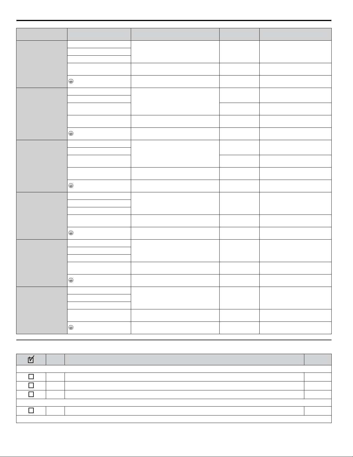
u
Wiring Checklist
No.
1 Check drive model number to ensure receipt of correct model. 10
2 Make sure you have the correct braking resistors, DC link chokes, noise filters, and other peripheral devices.
3 Check the option card model number.
4 Ensure that the area surrounding the drive complies with specifications. 13
24
Item Page(s)
Drive, Peripherals, Option Cards
Installation Area and Physical Setup
Power Supply Voltage, Output Voltage
YASKAWA TOEP YAIA1U 02A YASKAWA AC Drive – A1000 6-Phase/12-Pulse Input Installation Manual
Page 25
3 Electrical Installation
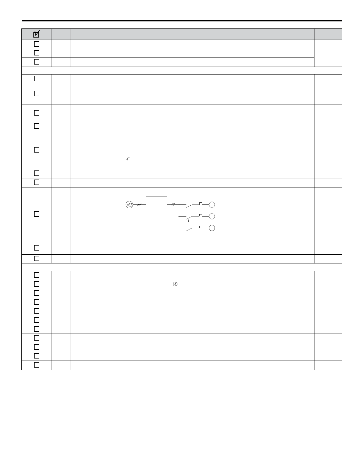
No. Item Page(s)
5 The voltage from the power supply should be within the input voltage specification range of the drive. –
6 The voltage rating for the motor should match the drive output specifications.
7 Verify that the drive is properly sized to run the motor.
Main Circuit Wiring
8 Confirm proper branch circuit protection as specified by national and local codes. 15
Properly wire the power supply to drive terminals R/L1, S/L2, T/L3, R1/L11, S1/L21, and T1/L31.
9
Note: Confirm that a 6-Phase/12-Pulse isolation transformer with each of the output windings phase-shifted
by 30 electrical degrees or a Hybrid 6-Phase topology is installed on the power supply.
Properly wire the drive and motor together.
10
The motor lines and drive output terminals U/T1, V/T2, and W/T3 should match in order to produce the desired phase
order. If the phase order is incorrect, the drive will rotate in the opposite direction.
11 Use 600 Vac vinyl-sheathed wire for the power supply and motor lines. 23
Use the correct wire gauges for the main circuit.
• Consider the amount of voltage drop when selecting wire gauges. Increase the wire gauge when the voltage drop is
12
greater than 2% of motor rated voltage. Ensure the wire gauge is suitable for the terminal block. Use the following
formula to calculate the amount of voltage drop:
Line drop voltage (V) = 3 × wire resistance (Ω/km) × wire length (m) × current (A) × 10
-3
• If the cable between the drive and motor exceeds 50 m, adjust the carrier frequency set to C6-02 accordingly.
13 Properly ground the drive. –
14 Tighten control circuit and grounding terminal screws. 23
Set up overload protection circuits when running multiple motors from a single drive.
Power supply
15
Drive
MC1
MC2
MCn
OL1
OL2
OLn
M1
M2
Mn
MC1 - MCn
OL 1 - OLn
... magnetic contactor
... thermal relay
10
18
–
23
–
Note: Close MC1 – MCn before operating the drive. MC1 – MCn cannot be switched off during run.
Install a magnetic contactor when using a dynamic braking option. Properly install the resistor and ensure that overload
16
protection shuts off the power supply using the magnetic contactor.
17 Verify phase advancing capacitors, input noise filters, or GFCIs are NOT installed on the output side of the drive. –
Control Circuit Wiring
18 Use twisted-pair line for all drive control circuit wiring. –
19
Ground the shields of shielded wiring to the GND terminal.
20 For 3-Wire sequence, set parameters for multi-function contact input terminals S1 – S8, and wire control circuits. –
21 Properly wire any option cards. –
22 Check for any other wiring mistakes. Only use a multimeter to check wiring. –
23 Properly fasten drive control circuit terminal screws. 23
24 Pick up all wire clippings. –
25 Ensure that no frayed wires on the terminal block are touching other terminals or connections. –
26 Properly separate control circuit wiring and main circuit wiring. –
27 Analog signal line wiring should not exceed 50 m. –
28 Safe Disable input wiring should not exceed 30 m. –
–
–
YASKAWA TOEP YAIA1U 02A YASKAWA AC Drive – A1000 6-Phase/12-Pulse Input Installation Manual
25
Page 26

4 Start-Up Programming & Operation
4 Start-Up Programming & Operation
u
Powering Up the Drive
Review the following checklist before applying power.
Item to Check Description
6-Phase/12-Pulse Isolated 380 to 480 Vac 50/60 Hz, 30 electrical degrees phase-shifted each phase
Power supply
Drive output terminals and
motor terminals
Control circuit terminals Check control circuit terminal connections.
Drive control terminal status Open all control circuit terminals (off).
Status of the load and connected
machinery
<1> Install a 6-Phase/12-Pulse isolation transformer with each of the output windings phase-shifted by 30 electrical degrees or use a Hybrid 6-Phase
topology.
Properly wire the power supply input terminals (R/L1, S/L2, T/L3, R1/L11, S1/L21, T1/L31).
Check for proper grounding of drive and motor.
Properly wire drive output terminals U/T1, V/T2, and W/T3 with motor terminals U, V, and W.
Decouple the motor from the load.
<1>
26
YASKAWA TOEP YAIA1U 02A YASKAWA AC Drive – A1000 6-Phase/12-Pulse Input Installation Manual
Page 27

5 Troubleshooting
5 Troubleshooting
NOTICE
Refer to the A1000 Technical Manual SIEP C710616 41 for information on Troubleshooting and complete product
instructions necessary for proper installation, set-up, troubleshooting and maintenance.
The A1000 Technical Manual is posted on the Yaskawa website, www.yaskawa.com.
WARNING
Electrical Shock Hazard
Do not connect or disconnect wiring while the power is on.
Failure to comply could result in death or serious injury.
Before servicing, disconnect all power to the equipment. The internal capacitor remains charged even after the power supply
is turned off. The charge indicator LED will extinguish when the DC bus voltage is below 50 Vdc. To prevent electric shock,
wait for at least the time specified on the warning label; after all indicators are OFF, measure for unsafe voltages to confirm
the drive is safe prior to servicing.
Do not operate equipment with covers removed.
Failure to comply could result in death or serious injury.
The diagrams in this section may illustrate drives without covers or safety shields to display details. Be sure to reinstall covers
or shields before operating the drives and run the drives according to the instructions described in this manual.
Do not touch terminals before the capacitors have fully discharged.
Failure to comply could result in death or serious injury.
Before servicing, disconnect all power to the equipment. The internal capacitor remains charged even after the power supply
is turned off. The charge indicator LED will extinguish when the DC bus voltage is below 50 Vdc. To prevent electric shock,
wait for at least the time specified on the warning label; after all indicators are OFF, measure for unsafe voltages to confirm
the drive is safe prior to servicing.
After blowing a fuse or tripping a GFCI, do not attempt to restart the drive or operate peripheral devices until five
minutes pass and CHARGE lamp is OFF.
Failure to comply could result in death, serious injury, and damage to the drive.
Check wiring and peripheral device ratings to identify the cause of trips.
Contact your supplier if the cause cannot be identified.
Installation, maintenance, inspection and servicing must be performed only by authorized personnel familiar with installation,
adjustment and maintenance of AC drives.
Do not perform work on the drive while wearing loose clothing, jewelry, or without eye protection.
Failure to comply could result in death or serious injury.
Do not remove covers or touch circuit boards while the power is on.
Failure to comply could result in death or serious injury.
YASKAWA TOEP YAIA1U 02A YASKAWA AC Drive – A1000 6-Phase/12-Pulse Input Installation Manual
27
Page 28

LO
RE
F2F1
ESC
RUN STOP
ENTERRESET
RESET
- MODE -
oC
Overcurrent
DRV
FWD
RESET
ALM
5 Troubleshooting
u
Fault Reset Methods
When a fault occurs, the cause of the fault must be removed and the drive must be restarted. The table below lists the different
ways to restart the drive.
After the Fault Occurs Procedure
Fix the cause of the fault, restart the drive, and
reset the fault
Resetting via Fault Reset Digital Input S4
Press on the digital operator when the error code
is displayed.
Close then open the fault signal digital input via
terminal S4. S4 is set for “Fault Reset” as default
(H1-04 = 14).
Fault Reset Switch
2
Drive
S4 Fault Reset Digital Input
SC Digital Input Common
ON
Turn off the main power supply if the above methods do not reset the fault. Reapply power after the
digital operator display has turned off.
1
OFF
Note: If the Run command is present, the drive will disregard any attempts to reset the fault. Remove the Run command before attempting to clear
a fault situation.
28
YASKAWA TOEP YAIA1U 02A YASKAWA AC Drive – A1000 6-Phase/12-Pulse Input Installation Manual
Page 29

6 Drive Options and Peripheral Devices
6 Drive Options and Peripheral Devices
Table 6 lists the names of the various peripheral devices, accessories, and options available for Yaskawa drives. Contact
Yaskawa or your Yaskawa agent to order these peripheral devices.
• Peripheral Device Selection: Refer to the Yaskawa catalog for selection and part numbers.
• Peripheral Device Installation: Refer to the corresponding option manual for installation instructions.
Table 6 Available Peripheral Devices
Option Model Number Description
Power Options
AC Reactor –
Braking Resistor –
Analog Input AI-A3
Analog Monitor AO-A3
Digital Input DI-A3
Digital Output DO-A3
Motor PG Feedback Line
Driver Interface
Motor PG Feedback Open
Collector Interface
EnDat Encoder PG-F3
Motor Feedback Resolver
Interface
PG-X3
PG-B3
PG-RT3
Protects the drive when operating from a large power supply and improves the power factor by
suppressing harmonic distortion. Highly recommended for power supplies that exceed 600 kVA.
For use with systems that require dynamic braking with up to 3% ED. If higher ED is required,
use a Braking Resistor Unit.
Input/Output Option Cards
• Allows high precision, high resolution analog reference input
• Input channels: 3
• Voltage input: -10 to 10 Vdc (20 kΩ), 13-bit signed
• Current input: 4 to 20 mA or 0 to 20 mA (250 Ω), 12-bit
• Provides extra multi-function analog output terminals
• Output channels: 2
• Output voltage: -10 to 10 V, 11-bit (signed)
• Sets the frequency reference by digital inputs
• Input channels: 18 (including SET signal and SIGN signal)
• Input signal type: BCD 16-bit (4-digit), 12-bit (3-digit), 8-bit (2-digit)
• Input signal: 24 Vdc, 8 mA
• Provides extra insulated multi-function digital outputs
• Photocoupler relays: 6 (48 V, up to 50 mA)
• Contact relays: 2 (250 Vac/up to 1 A, 30 Vdc/up to 1 A)
Motor Speed Feedback Option Cards
• For speed feedback input by connecting a motor encoder
• Input: 3-track (can be used with 1 or 2 tracks), line driver, 300 kHz max
• Pulse monitor: Matches RS-422 level
• Output: 3-track, line driver
• Encoder power supply: 5 V or 12 V, max current 200 mA
• For speed feedback input by connecting a motor encoder
• Input: 3-track (can be used with 1 or 2 tracks), HTL encoder connection, 50 kHz max
• Output: 3-track, open collector
• Encoder power supply: 12 V, max current 200 mA
• For speed feedback input by connecting a motor encoder
• Encoder type: EnDat 2.1/01, EnDat 2.2/01, and EnDat 2.2/ 22 (HEIDENHAIN), HIPERFACE
(SICK-STEGMANN)
• Maximum input frequency: 20 kHz
• Pulse monitor: Matches RS-422 level
• Output voltage: 5 V±5%, 8 V±10%
• Maximum output current: 200 mA
• Encoder power supply: 5 V, max current 330 mA or 8 V, max current 150 mA
• Wiring length: 20 m max. for the encoder, 30 m max. for the pulse monitor
Note: 1. Available in drive software versions PRG: 1018 and later.
2. The PG-F3 option can only be used in CLV/PM.
• For motor speed feedback by connecting a resolver that meets the specifications set by
Yaskawa.
• Input voltage: 10 Vac rms 10 kHz
• Transformation ratio: 0.5 ± 5%
• Maximum input current: 100 mA rms
Note: Available in drive software versions PRG: 1017 and later.
YASKAWA TOEP YAIA1U 02A YASKAWA AC Drive – A1000 6-Phase/12-Pulse Input Installation Manual
29
Page 30

6 Drive Options and Peripheral Devices
Option Model Number Description
Communication Option Cards
EtherNet/IP SI-EN3 Connects to an EtherNet/IP network.
Modbus TCP/IP SI-EM3 Connects to a Modbus TCP/IP network.
PROFINET SI-EP3 Connects to a PROFINET network.
LonWorks SI-W3 Connects to a LonWorks network.
DeviceNet SI-N3 Connects to a DeviceNet network
PROFIBUS-DP SI-P3 Connects to a PROFIBUS-DP network.
MECHATROLINK-II SI-T3 Connects to a MECHATROLINK-II network.
MECHATROLINK-III SI-ET3 Connects to a MECHATROLINK-III network.
BACnet SI-B3 Connects to a BACnet network.
EtherCAT SI-ES3 Connects to an EtherCAT network.
CC-Link
CANopen
<1>
<1>
LCD Operator JVOP-180
LED Operator JVOP-182 5-digit LED operator; max. cable length for remote usage: 3 m
Remote Operator Cable
USB Copy Unit JVOP-181
IP20/NEMA Type 1 Kit EZZ021136A-H Parts to make the drive conform to IP20/NEMA Type 1 enclosure requirements.
IP20/NEMA Type 1, 4, 12
Blank Keypad Kit
IP20/NEMA Type 1, 4, 12
Yaskawa Logo Keypad Kit
24 V Power Supply PS-A10HB Supplies the drive controller with 24 Vdc power during main power loss.
DriveWizard Industrial Contact Yaskawa PC tool for drive setup and parameter management
DriveWorksEZ Contact Yaskawa PC tool for enhanced programming of the drive
<1> Limited support. Contact a Yaskawa representative or the nearest Yaskawa sales office for assistance.
SI-C3 Connects to a CC-Link network.
SI-S3 Connects to a CANopen network.
Interface Options
Digital operator with 8 languages, clear text LCD display, and copy function; max. cable length
for remote usage: 3 m
UWR000051, 1 m cable
UWR000052, 2 m cable
RJ-45, 8-pin straight through, UTP CAT5e, extension cable (1 m or 2 m) to connect the digital
operator for remote operation.
• Allows the user to copy and verify parameter settings between drives.
• Functions as an adapter to connect the drive to a USB port on a PC.
Mechanical Options
UUX0000526
UUX0000527
Provides digital operator functionality on an enclosure designed for IP20/NEMA Type 1, 3R, 4,
4X, 12, or IPo6 environment. This keypad has a blank label on the front.
Provides digital operator functionality on an enclosure designed for IP20/NEMA Type 1, 3R, 4,
4X, 12, or IPo6 environment. This keypad has a Yaksawa brand label on the front.
Others
PC Software Tools
30
YASKAWA TOEP YAIA1U 02A YASKAWA AC Drive – A1000 6-Phase/12-Pulse Input Installation Manual
Page 31

Copy
Verify
Read
LOCK
YASKAWA
JVOP-181
USB Copy Unit
COM ERR
PC
DriveWizard X
Engineering Software Tools
DriveWorksEZ
Power
Supply
Line
Breaker
(MCCB)
or
Leakage
Breaker
Surge
Absorber
Input Side
Noise Filter
Braking Unit
(CDBR Type)
Braking
Resistor Unit
(LKEB Type)
Output Side
Noise Filter
Drive
Ground
+3 -
Motor
U/T1 V/T2 W/T3R1/L11
24 V Control
Power Supply
Unit
S1/L21 T1/L31R/L1
Fuse
S/L2 T/L3
Ground
USB Copy Unit
USB Type-AB Cable
(sold separately)
Operator
6-Phase/12-Pulse
Isolation Transformer
or
Hybrid 6-Phase
Topology
3-Phase Line Monitor
<1>
6 Drive Options and Peripheral Devices
u
Connecting Peripheral Devices
Figure 16 illustrates how to configure the drive and motor to operate with various peripheral devices.
Refer to the specific manual for the devices shown below for more detailed installation instructions.
Figure 16 Connecting Peripheral Devices
<1> With each of the output windings phase-shifted by 30 electrical degrees.
Note: If the drive is set to trigger a fault output when the fault restart function is activated (L5-02 = 1), then a sequence to interrupt power when
a fault occurs will turn off the power to the drive while the drive attempts to restart. The default setting for L5-02 is 0 (fault output active
during restart).
YASKAWA TOEP YAIA1U 02A YASKAWA AC Drive – A1000 6-Phase/12-Pulse Input Installation Manual
31
Page 32

Dynamic Braking Resistor
Thermal Relay
Trip Contact
B1
B2
P 1
B 2
Drive
6 Drive Options and Peripheral Devices
u
Installing Peripheral Devices
This section describes the proper steps and precautions to take when installing or connecting various peripheral devices to the
drive.
NOTICE: Use a class 2 power supply when connecting to the control terminals. Improper application of peripheral devices could result in
drive performance degradation due to improper power supply. Refer to NEC Article 725 Class 1, Class 2, and Class 3 Remote-Control,
Signaling, and Power Limited Circuits for requirements concerning class 2 power supplies.
Dynamic Braking Options
n
Dynamic braking (DB) helps bring the motor to a smooth and rapid stop when working with high inertia loads. As the drive
lowers the frequency of a motor moving a high inertia load, regeneration occurs. This can cause an overvoltage situation when
the regenerative energy flows back into the DC bus capacitors. A braking resistor prevents these overvoltage faults.
Refer to CDBR manual TOBP C720600 00 or TOBP C720600 01 when connecting a dynamic braking option to the drive.
NOTICE: Do not allow unqualified personnel to use the product. Failure to comply could result in damage to the drive or braking circuit.
Carefully review CDBR manual TOBP C720600 00 or TOBP C720600 01 when connecting a dynamic braking option to the drive.
Note: 1. Properly size the braking circuit to dissipate the power required to decelerate the load in the desired time. Ensure that the braking circuit
WARNING! Fire Hazard. The dynamic braking resistor connection terminals are B1 and B2 on models 4T0058o and 4T0072o. Do not
connect a dynamic braking resistor directly to any other terminals. Improper wiring connections could result in death or serious injury by fire.
Failure to comply may result in damage to the braking circuit or drive.
WARNING! Fire Hazard. The CDBR dynamic braking unit connection terminals are ⊖ and ⊕3 on models 4T0088o to 4T0675o. Do not
connect a CDBR dynamic braking unit directly to any other terminals. Improper wiring connections could result in death or serious injury by
fire. Failure to comply may result in damage to the braking circuit or drive.
NOTICE: Connect dynamic braking to the drive as shown in the I/O wiring examples. Improperly wiring braking circuits could result in damage
to the drive or equipment.
can dissipate the energy for the set deceleration time prior to running the drive.
2. Set L8-55 to 0 to disable the internal braking transistor of the drive protection when using braking resistor options.
Installing a Dynamic Braking Resistor
Dynamic braking resistors connect to drive terminals B1 and B2 on models 4T0058o and 4T0072o as shown in Figure 17.
Utilize the thermal overload contact to switch off the drive in the event of braking resistor overheat.
The internal braking resistor overload protection of the drive cannot protect dynamic braking resistors. Set L8-01 to 0 to disable
this function.
Figure 17 Connecting a Dynamic Braking Resistor
Installing Other Types of Dynamic Braking Resistors
When installing non-Yaskawa dynamic braking resistors, make sure that the braking transistor in the braking unit will not be
overloaded with the required duty cycle and the selected resistance value. Use a resistor that is equipped with a thermal overload
relay contact, and utilize this contact to disconnect main power to the drive in case of braking resistor overheat.
32
YASKAWA TOEP YAIA1U 02A YASKAWA AC Drive – A1000 6-Phase/12-Pulse Input Installation Manual
Page 33

Drive
400 V
MC
R
S
T
CDBR dynamic
braking unit
<1>
Dynamic
braking
resistor
<2>
1 2
+3 -
MC
2MCCB
MB ON
OFFTHRX
SA
1
2
TRX
MC
MA
TRX
Fault Relay
Contact
Braking Resistor Unit
Thermal Relay Trip Contact
MC
MC
SA
SA
THRX
R/L1
S/L2
T/L3
R1/L11
S1/L21
T1/L31
Y
Δ
Δ
6 Drive Options and Peripheral Devices
Dynamic Braking Resistor Overload Protection
When using a dynamic braking resistor option, interrupt the power supply using a sequence such as the one shown in Figure
18 for protection in the event of braking resistor overheat.
Figure 18 Power Supply Interrupt for Dynamic Braking Resistor Overheat Protection
<1> A CDBR dynamic braking unit cannot be connected to models 4T0058o or 4T0072o.
<2> A dynamic braking resistor can be connected to the B1 and B2 terminals on models 4T0058o and 4T0072o.
Installing a CDBR Dynamic Braking Unit
Connect the ⊕3 terminal from the drive to the positive terminal on the CDBR dynamic braking unit and wire together the
negative terminals on the drive and CDBR dynamic braking unit.
Connect the dynamic braking resistor to CDBR dynamic braking unit terminals ⊕0 and ⊖0. Refer to Figure 18 and Figure
19 for proper configuration.
Wire the thermal overload relay normally open contacts of the CDBR dynamic braking unit and the dynamic braking resistor
in parallel, and connect this signal to a control circuit as shown in Figure 18 to interrupt the main input power supply to the
drive in the event of an overload.
Set L8-55 to 0 to disable dynamic braking transistor protection.
YASKAWA TOEP YAIA1U 02A YASKAWA AC Drive – A1000 6-Phase/12-Pulse Input Installation Manual
33
Page 34

Thermal Relay
Trip Contact
Drive
CDBR dynamic
braking unit
Thermal Overload
Protector Trip Contact
1
2
P
3 4
3 + + 0
− − 0
B
+
−
Dynamic braking
resistor
6 Drive Options and Peripheral Devices
Figure 19 Connecting a CDBR Dynamic Braking Unit and Dynamic Braking Resistor on Models 4T0088o to 4T0675o
Note:
To install a CDBR dynamic braking unit to models 4T0058o and 4T0072o with built-in dynamic braking transistors, first connect terminal
B1 to the positive terminal on the CDBR dynamic braking unit, then wire the negative terminals on the drive and braking unit together.
Terminal B2 is not used.
34
YASKAWA TOEP YAIA1U 02A YASKAWA AC Drive – A1000 6-Phase/12-Pulse Input Installation Manual
Page 35

7 Periodic Inspection & Maintenance
7 Periodic Inspection & Maintenance
u
Drive Cooling Fans
Contact a Yaskawa representative or the nearest Yaskawa sales office to order replacement cooling fans as required.
For drives with multiple cooling fans, replace all the fans when performing maintenance to ensure maximum product
performance life.
Number of Cooling Fans
n
Drive Model Cooling Fans Circulation Fans Control Board Cooling Fans
4T0058o
4T0072o
4T0088o
4T0103o
4T0139o
4T0165o
4T0208o
4T0250o
4T0296o
4T0362o
4T0414o
4T0515o
4T0675o
2 – –
2 – –
2 – –
2 – –
2 – –
2 – –
2 – –
3 – –
3 – –
3 1 –
3 1 –
3 2 2
3 2 2
Cooling Fan Replacement
n
NOTICE
Refer to the A1000 Technical Manual SIEP C710616 41 for information on Cooling Fan Replacement and complete product
instructions necessary for proper maintenance.
The A1000 Technical Manual is posted on the Yaskawa website, www.yaskawa.com.
YASKAWA TOEP YAIA1U 02A YASKAWA AC Drive – A1000 6-Phase/12-Pulse Input Installation Manual
35
Page 36

C
E
G
D
B
4T0058 to 4T0103
4T0139 to 4T0362
A
D
4T0414
4T0414 and 4T0675
7 Periodic Inspection & Maintenance
Cooling Fan Component Names
n
WARNING! Electrical Shock Hazard. Do not connect or disconnect wiring while the power is on. Failure to comply can result in serious
personal injury. Before servicing the drive, disconnect all power to the equipment. The internal capacitor remains charged even after the
power supply is turned off. After shutting off the power, wait for at least the amount of time specified on the drive before touching any
components.
CAUTION! Burn Hazard. Do not touch a hot drive heatsink. Failure to comply could result in minor or moderate injury. Shut off the power
to the drive when replacing the cooling fan. To prevent burns, wait at least 15 minutes and ensure the heatsink has cooled down.
A – Fan finger guard
B – Fan guard
C – Cable cover
D – Cooling fan
E – Fan bracket
F – Circulation fan base
G – Circulation fan
H – Circuit board cooling fan
I – Circuit board cooling fan unit case
Figure 20 Cooling Fan Component Names
36
YASKAWA TOEP YAIA1U 02A YASKAWA AC Drive – A1000 6-Phase/12-Pulse Input Installation Manual
Page 37

7 Periodic Inspection & Maintenance
u
Gasket Replacement for Flange Type Enclosures
Gasket Replacement Procedure
n
Use a plastic scraper to remove the damaged or torn gasket without scratching the mounting surfaces.
1.
Peel off the adhesive cover from the replacement gasket.
2.
Align the holes on the mounting flange or fan bracket with the holes on the replacement gasket and apply the new
3.
gasket.
Gasket Replacement Parts
n
Each replacement part contains two gaskets in the event that a gasket is torn during application.
Contact a Yaskawa representative or the nearest Yaskawa sales office to order replacement gaskets as required.
Table 7 Gasket Replacement Part Numbers
Drive Model Replacement Part Part Number
4T0058U Mounting Flange Gasket UGK00418-A
4T0072U Mounting Flange Gasket UGK00419-A
4T0088U
4T0103U
4T0139U
4T0165U
4T0208U Fan Bracket Gasket UGK00422-A
4T0250U
4T0296U
4T0362U
4T0414U Fan Bracket Gasket UGK00424-A
4T0515U
4T0675U
Mounting Flange Gasket UGK00420-A
Fan Bracket Gasket UGK00421-A
Fan Bracket Gasket UGK00423-A
Fan Bracket Gasket UGK00425-A
YASKAWA TOEP YAIA1U 02A YASKAWA AC Drive – A1000 6-Phase/12-Pulse Input Installation Manual
37
Page 38

8 Specifications
8 Specifications
u
Power Ratings for Models 4T0058o to 4T0208o
Table 8 Power Ratings for Models 4T0058o to 4T0208o
Item Specification
Drive Model
Maximum Applicable Motor
Capacity kW (HP)
Input Current (A)
<1>
<2>
ND Rating
HD Rating
ND Rating 54 66 79 97 131 156 190
HD Rating 40 54 66 79 97 131 156
Rated Voltage
Rated Frequency
Input
Allowable Voltage Fluctuation -15 to 10%
Allowable Frequency Fluctuation ±5%
ND Rating 53.0 64.9 78.6 96.0 130 156 189
HD Rating 39.3 53.0 64.9 78.6 96.0 130 155
ND Rating
HD Rating 34 48 57 69 85 114
ND Rating
HD Rating
Output
Input Power (kVA)
Rated Output
Capacity (kVA)
<3>
Rated Output
Current (A)
Overload Tolerance
Carrier Frequency User adjustable between 1 and 15 kHz
Maximum Output Voltage (V) Three-phase: 380 to 480 Vac (proportional to input voltage)
Maximum Output Frequency (Hz) 400 Hz (user-adjustable)
<1> The motor capacity (HP) refers to a NEC rated 4-pole motor. The rated output current of the drive output amps should be equal to or greater than
the motor current. Select the appropriate capacity drive if operating the motor continuously above motor nameplate current.
<2> Assumes operation at the rated output current. Input current rating varies depending on the power supply transformer, input reactor, wiring conditions,
and power supply impedance. This input current rating is the 3-Phase total input current rating. Refer to Alternative AC Drive Branch Circuit
Protection on page 85 for the 6-Phase input current rating.
<3> Rated motor capacity is calculated with a rated output voltage of 440 V.
<4> Carrier frequency is set to 2 kHz. Current derating is required in order to raise the carrier frequency.
<5> Carrier frequency can be increased to 8 kHz while keeping this current derating. Higher carrier frequency settings require derating.
<6> Carrier frequency can be increased to 5 kHz while keeping this current derating. Higher carrier frequency settings require derating.
4T0058o 4T0072o 4T0088o 4T0103o 4T0139o 4T0165o 4T0208o
30
(40)
22
(25-30)
37
(50)
30
(40)
45
(60)
37
(50-60)
55
(75)
45
(50-60)
75
(100)
55
(75)
90
(125)
75
(100)
6-Phase/12-Pulse: 380 Vac to 480 Vac 50/60 Hz
Note: 6-Phase isolated supply with each of the output windings phase-shifted
by 30 electrical degrees or Hybrid 6-phase topology.
<4>
<4>
44 55 67 78 106 126 159
58 72 88 103 139 165 208
45
<5>
60
<5>
75
<5>
91
<5>
112
<5>
150
<6>
ND Rating: 120% of rated output current for 60 s
HD Rating: 150% of rated output current for 60 s
(Derating may be required for applications that start and stop frequently)
User adjustable between
1 and 10 kHz
110
(150)
90
(125-150)
<6>
137
<6>
180
38
YASKAWA TOEP YAIA1U 02A YASKAWA AC Drive – A1000 6-Phase/12-Pulse Input Installation Manual
Page 39

8 Specifications
u
Power Ratings for Models 4T0250o to 4T0675o
Table 9 Power Ratings for Models 4T0250o to 4T0675o
Item Specification
Drive Model
Maximum Applicable Motor
Capacity kW (HP)
Input Current (A)
<1>
<2>
ND Rating
HD Rating
ND Rating 228 275 317 376 427 603
HD Rating 190 228 275 317 376 511
Rated Voltage
Rated Frequency
Input
Allowable Voltage Fluctuation -15 to 10%
Allowable Frequency Fluctuation ±5%
Input Power (kVA)
Rated Output
Capacity (kVA)
<3>
Rated Output
ND Rating 227 274 316 375 425 601
HD Rating 189 227 275 316 375 534
ND Rating
<4>
HD Rating
ND Rating
<4>
Current (A)
Output
HD Rating
Overload Tolerance
Carrier Frequency User adjustable between 1 and 10 kHz User adjustable between 1 and 5 kHz
Maximum Output Voltage (V) Three-phase: 380 to 480 Vac (proportional to input voltage)
Maximum Output Frequency (Hz) 400 Hz (user-adjustable)
<1> The motor capacity (HP) refers to a NEC rated 4-pole motor. The rated output current of the drive output amps should be equal to or greater than
the motor current. Select the appropriate capacity drive if operating the motor continuously above motor nameplate current.
<2> Assumes operation at the rated output current. Input current rating varies depending on the power supply transformer, input reactor, wiring conditions,
and power supply impedance. This input current rating is the 3-Phase total input current rating. Refer to Alternative AC Drive Branch Circuit
Protection on page 85 for the 6-Phase input current rating.
<3> Rated motor capacity is calculated with a rated output voltage of 440 V.
<4> Carrier frequency is set to 2 kHz. Current derating is required in order to raise the carrier frequency.
<5> Carrier frequency can be increased to 5 kHz while keeping this current derating. Higher carrier frequency settings require derating.
4T0250o 4T0296o 4T0362o 4T0414o 4T0515o 4T0675o
132
(200)
110
(150)
160
(250)
132
(200)
185
(300)
160
(250)
220
(350)
185
(300)
250
(400)
220
(350)
355
(500-550)
315
(400-450-500)
6-Phase/12-Pulse: 380 Vac to 480 Vac 50/60 Hz
Note: 6-Phase isolated supply with each of the output windings phase-shifted
by 30 electrical degrees or Hybrid 6-phase topology.
191 226 276 316 392 514
165
<5>
198
<5>
232
<5>
282
<4>
343
<4>
461
<4>
250 296 362 414 515 675
216
<5>
260
<5>
304
<5>
370
<4>
450
<4>
605
<4>
ND Rating: 120% of rated output current for 60 s
HD Rating: 150% of rated output current for 60 s
(Derating may be required for applications that start and stop frequently)
YASKAWA TOEP YAIA1U 02A YASKAWA AC Drive – A1000 6-Phase/12-Pulse Input Installation Manual
39
Page 40

8 Specifications
u
Drive Specifications
Note: 1. Perform rotational Auto-Tuning to obtain the performance specifications given below.
2. For optimum performance life of the drive, install the drive in an environment that meets the required specifications.
Item Specification
The following control methods can be set using drive parameters:
• V/f Control (V/f)
• V/f Control with PG (V/f w/PG)
• Open Loop Vector Control (OLV)
• Closed Loop Vector Control (CLV)
• Open Loop Vector Control for PM (OLV/PM)
• Advanced Open Loop Vector Control for PM (AOLV/PM)
• Closed Loop Vector Control for PM (CLV/PM)
Digital input: within ±0.01% of the max output frequency (-10 to +40 °C)
Analog input: within ±0.1% of the max output frequency (25 °C ±10 °C)
Digital inputs: 0.01 Hz
Analog inputs: 1/2048 of the maximum output frequency setting (11 bit plus sign)
Main speed frequency reference: DC -10 to +10 V (20 kΩ), DC 0 to +10 V (20 kΩ),
4 to 20 mA (250 Ω), 0 to 20 mA (250 Ω)
Main speed reference: Pulse train input (max. 32 kHz)
V/f, V/f w/PG: 150% at 3 Hz
OLV: 200% at 0.3 Hz
<1>
CLV, AOLV/PM, CLV/PM: 200% at 0.0 r/min
OLV/PM: 100% at 3 Hz
V/f, V/f w/PG: 1:40
OLV: 1:200
<2>
CLV, CLV/PM: 1:1500
OLV/PM: 1:20
AOLV/PM: 1:100
OLV: ±0.2% (25 °C ±10 °C)
<2>
CLV: ±0.02% (25 °C ±10 °C)
OLV, OLV/PM, AOLV/PM: 10 Hz (25 °C ±10 °C (77 °F ±50 °F))
CLV, CLV/PM: 50 Hz (25 °C ±10 °C (77 °F ±50 °F))
Parameters setting allow separate limits in four quadrants
(available in OLV, CLV, AOLV/PM, CLV/PM)
Approx. 20% (approx. 125% when using braking resistor)
•
Short-time decel torque
over 20% for 2.2 kW and above motors
•
Continuous regenerative torque: approx. 20%
<3>
option
: 10% ED, 10s)
<4>
: over 100% for 0.4/ 0.75 kW motors, over 50% for 1.5 kW motors, and
<5>
Torque Control, Droop Control, Speed/torque Control Switching, Feed Forward Control, Zero Servo
Function, Momentary Power Loss Ride-Thru, Speed Search, Overtorque/Undertorque Detection,
Torque Limit, 17 Step Speed (max), Accel/decel Switch, S-curve Accel/decel, 3-wire Sequence, AutoTuning (rotational, stationary tuning), Dwell, Cooling Fan on/off Switch, Slip Compensation, Torque
Compensation, Frequency Jump, Upper/lower Limits for Frequency Reference, DC Injection Braking
at Start and Stop, Overexcitation Braking, High Slip Braking, PID Control (with sleep function), Energy
Saving Control, MEMOBUS/Modbus Comm. (RS-422/RS-485 max, 115.2 kbps), Fault Restart,
Application Presets, DriveWorksEZ (customized function), Removable Terminal Block with Parameter
Backup Function, Online Tuning, KEB, Overexcitation Deceleration, Inertia (ASR) Tuning,
Overvoltage Suppression, High Frequency Injection.
Control
Character-
istics
Control Method
Frequency Control Range 0.01 to 400 Hz
Frequency Accuracy
(Temperature Fluctuation)
Frequency Setting Resolution
Output Frequency Resolution 0.001 Hz
Frequency Setting Signal
Starting Torque
<2>
Speed Control Range
Speed Control Accuracy
Speed Response
<2>
Torque Limit
Accel/Decel Time 0.0 to 6000.0 s (4 selectable combinations of independent acceleration and deceleration settings)
Braking Torque
V/f Characteristics User-selected programs and V/f preset patterns possible
Main Control Functions
<1>
<3>
(overexcitation braking/High Slip Braking: approx. 40%)
<5>
(approx. 125% with dynamic braking resistor
40
YASKAWA TOEP YAIA1U 02A YASKAWA AC Drive – A1000 6-Phase/12-Pulse Input Installation Manual
Page 41

8 Specifications
Item Specification
Motor Protection Electronic thermal overload relay
Momentary Overcurrent
Protection
Overload Protection
Overvoltage Protection Stops when DC bus voltage exceeds approx. 820 V
Undervoltage Protection Stops when DC bus voltage falls below approx. 380 V
Protection
Functions
Momentary Power Loss
Ride-Thru
Heatsink Overheat Protection Thermistor
Braking Resistor Overheat
Protection
Stall Prevention Stall Prevention is available during acceleration, deceleration, and during run.
Ground Protection
DC Bus Charge LED Remains lit until DC bus voltage falls below 50 V
Area of Use Indoors
Ambient Temperature
Environment
Humidity 95 RH% or less (no condensation)
Storage Temperature -20 °C to +60 °C (short-term temperature during transportation)
Altitude Up to 1000 meters without derating, up to 3000 m with output current and voltage derating.
Vibration/Shock
Standard
Protection Design
<1> Select control modes in accordance with drive capacity.
<2> The accuracy of these values depends on motor characteristics, ambient conditions, and drive settings. Specifications may vary with different motors
and with changing motor temperature. Contact Yaskawa for consultation.
<3> Disable Stall Prevention during deceleration (L3-04 = 0) when using a regenerative converter, a regenerative unit, a braking resistor or the Braking
Resistor Unit. The default setting for the Stall Prevention function will interfere with the braking resistor.
<4> Instantaneous average deceleration torque refers to the torque required to decelerate the motor (uncoupled from the load) from the rated motor speed
down to zero in the shortest time.
<5> Actual specifications may vary depending on motor characteristics.
<6> Overload protection may be triggered when operating with 150% of the rated output current if the output frequency is less than 6 Hz.
<7> May be shorter due to load conditions and motor speed.
<8> Ground protection cannot be provided when the impedance of the ground fault path is too low, or when the drive is powered up while a ground
fault is present at the output.
Drive stops when output current exceeds 200% of Heavy Duty Rating
Drive stops after 60 s at 150% of rated Heavy Duty output current
Immediately stop after 15 ms or longer power loss
<7>
.
<6>
Continuous operation during power loss than 2 s (standard)
Overheat input signal for braking resistor (Optional ERF-type, 3% ED)
Electronic circuit protection
<8>
Flange Type Enclosure: -10 °C to +40 °C (14 °F to 104 °F)
Non-Flange Type Enclosure: -10 °C to +50 °C (14 °F to 122 °F)
10 Hz to 20 Hz: 9.8 m/s
2
20 Hz to 55 Hz: 5.9 m/s2 (4T0058o to 4T0165o) or 2.0 m/s2 (4T0208o to 4T0675o)
• UL508C
• IEC/EN 61800-3, IEC/EN 61800-5-1
• Two Safe Disable inputs and one EDM output according to ISO/EN 13849-1 Cat. 3 PLd, IEC/EN
61508 SIL2
Flange Type Enclosure (NEMA Type 12 Backside)
Open-Type (Non-Flange) Enclosure
YASKAWA TOEP YAIA1U 02A YASKAWA AC Drive – A1000 6-Phase/12-Pulse Input Installation Manual
41
Page 42

8 Specifications
u
Drive Watt Loss Data
Table 10 Drive Watt Loss
Normal Duty Heavy Duty
Drive Model
4T0058o
4T0072o
4T0088o
4T0103o
4T0139o
4T0165o
4T0208o
4T0250o
4T0296o
4T0362o
4T0414o
4T0515o
4T0675o
<1> Value assumes the carrier frequency is set to 8 kHz or less.
<2> Value assumes the carrier frequency is set to 5 kHz or less.
<3> Value assumes the carrier frequency is set to 2 kHz.
Rated
Amps (A)
<3>
58 197 453 650
72 244 588 832
88 285 669 954
103 329 827 1156
139 487 1179 1666
165 624 1520 2164
208 553 1746 2299
250 729 2305 3034
296 772 2308 3080
362 874 3168 4042
414 1083 3443 4526
515 1474 4850 6324
675 1789 4861 6650
Internal External Total
Rated
Amps (A)
<1>
45
<1>
60
<1>
75
<1>
91
<1>
112
<2>
150
<2>
180
<2>
216
<2>
260
<2>
304
<1>
370
<1>
450
<1>
605
Internal External Total
159 341 500
206 477 683
241 556 797
285 714 999
447 1100 1547
629 1647 2276
586 2199 2765
663 2308 2971
694 2295 2989
788 3075 3863
1012 3578 4590
1234 3972 5206
1504 4191 5695
u
Drive Derating Data
Temperature Derating
n
To ensure the maximum performance life, the drive output current must be derated as shown in Figure 21 when the drive is
installed in areas with high ambient temperature or if drives are mounted side-by-side in a cabinet. Set parameter L8-35 to 3
for all 6-Phase/12-Pulse Flange and Non-Flange models to ensure reliable drive overload protection.
Parameter Settings
n
No. Name Description Range Def.
L8-12
Ambient
Temperature Setting
Adjust the drive overload (oL2) protection level when the drive is installed
in an environment that exceeds its ambient temperature rating.
-10 to +50 +40 °C
0: IP00/Open-Chassis Enclosure
1: Side-by-Side Mounting
L8-35
Installation Method
Selection
2: IP20/NEMA Type 1 Enclosure
3: Finless Drive or External Heatsink Installation
0 to 3
<1>
Note: Set this parameter to 3 for all 6-Phase/12-Pulse Flange and
Non-Flange models.
<1> Set this parameter to 3 for all 6-Phase/12-Pulse Flange and Non-Flange models. Default setting is determined by drive model.
Setting 0: (Models 4T0208o to 4T0675o)
Setting 2: (Models 4T0058o to 4T0165o).
Setting 0: IP00/Open-Chassis Enclosure
Drive operation between -10 °C and +50 °C allows 100% continuous current without derating.
Setting 1: Side-by-Side Mounting
Drive operation between -10 °C and +30 °C allows 100% continuous current without derating. Operation between +30 °C and
+50 °C requires output current derating.
Setting 2: IP20/NEMA Type 1 Enclosure
Drive operation between -10 °C and +40 °C allows 100% continuous current without derating. Operation between +40 °C and
+50 °C requires output current derating.
42
YASKAWA TOEP YAIA1U 02A YASKAWA AC Drive – A1000 6-Phase/12-Pulse Input Installation Manual
Page 43

100
85
70
55
0
L8-35 = 2: IP20/NEMA Type 1 Enclosure
L8-35 = 3: External Heatsink lnstallation
L8-35 = 0: IP00/Open-Chassis Enclosure
30
-10
40
50
Drive Rating
(%)
L8-12
(Ambient temp: °C)
L8-35 = 1: Side-by-Side Mounting
8 Specifications
Setting 3: External Heatsink Installation, Finless Drive
Drive operation between -10 °C and +40 °C allows 100% continuous current without derating. Operation between +40 °C and
+50 °C requires output current derating.
Figure 21 Ambient Temperature and Installation Method Derating
Altitude Derating
n
The drive standard ratings are valid for installation altitudes up to 1000 m. For installations from 1000 m to 3000 m, the drive
rated voltage and the rated output current must be derated for 0.2% per 100 m.
YASKAWA TOEP YAIA1U 02A YASKAWA AC Drive – A1000 6-Phase/12-Pulse Input Installation Manual
43
Page 44

8 Specifications
u
External Mounting and Panel Cutout Dimensions
Table 11 External Mounting and Panel Cutout Dimensions Reference
Model
4T0058U 45 61
4T0072U 46 62
4T0088U
4T0103U
4T0139U
4T0165U
4T0208U 49 65
4T0250U
4T0362U
4T0414U 51 67
4T0515U
4T0675U
4T0058A 53 69
4T0072A 54 70
4T0088A
4T0103A
4T0139A
4T0165A
4T0208A 57 73
4T0250A
4T0362A
4T0414A 59 75
4T0515A
4T0675A
External Mounting Dimensions
Flange Type Models
Non-Flange Type Models
Page
Panel Cutout Dimensions
47 63
48 64
50 664T0296U
52 68
55 71
56 72
58 744T0296A
60 76
Page
44
YASKAWA TOEP YAIA1U 02A YASKAWA AC Drive – A1000 6-Phase/12-Pulse Input Installation Manual
Page 45

External Mounting Dimensions
Eye Bolts
with M8 Screw
8-Mounting Holes for M6 Screw
97 (3.82)
258 (10.16)
3
(0.12)
153.6 (6.05)
8.5 (0.33) 96.5 (3.80) 250 (9.84) 96.5 (3.80)
470.2 (18.51)
412.2 (16.23)
23.9 (0.94)
23.9 (0.94)
460 (18.11)
280.2 (11.03)
330 (12.99)
103 (4.06) 103 (4.06)
153.8 (6.06) 153.8 (6.06)
239 (9.41)
unit: mm (inch)
n
Mounting Dimensions for Flange Type 4TooooU Models
8 Specifications
Figure 22 Flange Type Model 4T0058U Mounting Dimensions
YASKAWA TOEP YAIA1U 02A YASKAWA AC Drive – A1000 6-Phase/12-Pulse Input Installation Manual
45
Page 46

unit: mm (inch)
12-Mounting Holes for M6 Screw
Eye Bolts
with M8 Screw
163.3 (6.43)
3
(0.12)
292 (11.50)
258 (10.16)
150 (5.91) 170 (6.69) 150 (5.91)
330.2 (13.00)
390 (15.35)
473.2 (18.63)
542 (21.34)
101 (3.98)
25.5 (1.00)
25.5 (1.00)
45.1 (1.78)
10.5 (0.41)
23.7 (0.93)
124 (4.88) 124 (4.88)
176.75 (6.96) 176.75 (6.96)
8 Specifications
Figure 23 Flange Type Model 4T0072U Mounting Dimensions
46
YASKAWA TOEP YAIA1U 02A YASKAWA AC Drive – A1000 6-Phase/12-Pulse Input Installation Manual
Page 47

unit: mm (inch)
12-Mounting Holes for M6 Screw
Eye Bolts
with M8 Screw
163.3 (6.43)
3
(0.12)
292 (11.50)
258 (10.16)
150 (5.91) 170 (6.69) 150 (5.91)
330.2 (13.00)
390 (15.35)
473.2 (18.63)
542 (21.34)
101 (3.98)
25.5 (1.00)
25.5 (1.00)
45.1 (1.78)
10.5 (0.41)
23.7 (0.93)
124 (4.88) 124 (4.88)
176.75 (6.96) 176.75 (6.96)
8 Specifications
Figure 24 Flange Type Models 4T0088U and 4T0103U Mounting Dimensions
YASKAWA TOEP YAIA1U 02A YASKAWA AC Drive – A1000 6-Phase/12-Pulse Input Installation Manual
47
Page 48

unit: mm (inch)
Eye Bolts
with M8 Screw
12-Mounting Holes for M6 Screw
283 (11.14)
3
(0.12)
199.8 (7.87)
132.6 (5.22)
324 (12.76)
386 (15.20)
130.5 (5.14)
130.5 (5.14)
179.1 (7.06) 179.1 (7.06)
165 (6.50) 161 (6.34) 165 (6.50) 27 (1.06)
24.5 (0.96)
512.7 (20.19)
24.9 (0.98)
562 (22.13)
568 (22.36)
106.9
(4.21)
130.5
(5.14)
130.5
(5.14)
27 (1.06)
8.5 (0.33)
8 Specifications
Figure 25 Flange Type Models 4T0139U and 4T0165U Mounting Dimensions
48
YASKAWA TOEP YAIA1U 02A YASKAWA AC Drive – A1000 6-Phase/12-Pulse Input Installation Manual
Page 49

unit: mm (inch)
Eye Bolts
with M10 Screw
13-Mounting Holes for M10 Screw
330 (12.99)
3
(0.12)
157.5 (6.20)
127 (5.00)
36 (1.42)
218 (8.58) 190 (7.48) 218 (8.58)
36 (1.42)
455.2 (17.92)
560 (22.05)
170 (6.69) 170 (6.69)
15 (0.59)
250 (9.84) 250 (9.84)
39.1
(1.54)
38.7
(1.52)
647.2 (25.48)
725 (28.54)
570 (22.44)
8 Specifications
Figure 26 Flange Type Models 4T0208U Mounting Dimensions
YASKAWA TOEP YAIA1U 02A YASKAWA AC Drive – A1000 6-Phase/12-Pulse Input Installation Manual
49
Page 50

13-Mounting Holes
for M10 Screw
350 (13.78)
3
(0.12)
160 (6.30) 175 (6.89)
270.6 (10.65)
37.4 (1.47)
225 (8.86)
225 (8.86) 241.4 (9.50)
175 (6.89)
500 (19.69)
730.7 (28.77)
175 (6.89) 125 (4.92)125 (4.92)
20.6
(0.81)
15 (0.59)
270.6 (10.65)
590 (23.22)
600 (23.62)
820 (32.28)
555 (21.85)
37.4
(1.47)
44.9 (1.77)
132.5 (5.22)
44.4
(1.75)
132.5
(5.22)
unit: mm (inch)
Eye Bolts
with M10 Screw
126.7
(4.99)
170.1
(6.70)
8 Specifications
Figure 27 Flange Type Models 4T0250U to 4T0362U Mounting Dimensions
50
YASKAWA TOEP YAIA1U 02A YASKAWA AC Drive – A1000 6-Phase/12-Pulse Input Installation Manual
Page 51

Eye Bolts
with M12 Screw
131.8
(5.19)
174
(6.84)
151.25
(5.95)
151.25
(5.95)
151.25
(5.95)
151.25
(5.95)
167.5
(6.59)
167.5
(6.59)
167.5
(6.59)
167.5
(6.59)
112
(4.41)
3
(0.12)
370 (14.57)
500 (19.69)
160
(6.30)
54.8 (2.16)
645 (25.39)
1105.4 (43.52)
861.4 (33.91)
956 (37.64)
74.8 (2.94)
121.7 (4.79)
122.3 (4.81)
74.6 (2.94)
123.4
(4.86)
unit: mm (inch)
22-Mounting Holes
for M10 Screw
8 Specifications
Figure 28 Flange Type Model 4T0414U Mounting Dimensions
YASKAWA TOEP YAIA1U 02A YASKAWA AC Drive – A1000 6-Phase/12-Pulse Input Installation Manual
51
Page 52

Eye Bolts
with M12 Screw
146.8
(5.78)
183
(7.20)
193 (7.60) 193 (7.60) 193 (7.60) 193 (7.60)
781.2 (30.76)
670 (26.38)
370 (14.57)
3.7
(0.12)
182
(7.17)
182
(7.17)
182
(7.17)
182
(7.17)
182
(7.17)
182
(7.17)
182
(7.17)
17 (0.67)
39.1 (1.54)
1308 (51.50)
812 (31.97)
1193.2 (46.98)
1044.6 (41.13)
56.1 (2.21)
130.9 (5.15)
58.7 (2.31)
132.5 (5.22)
unit: mm (inch)
22-Mounting Holes
for M10 Screw
8 Specifications
Figure 29 Flange Type Models 4T0515U and 4T6075U Mounting Dimensions
52
YASKAWA TOEP YAIA1U 02A YASKAWA AC Drive – A1000 6-Phase/12-Pulse Input Installation Manual
Page 53

Mounting Dimensions for Non-Flange Type 4TooooA Models
AIR
AIR
HORIZONTAL MTG DIM
VERTICAL MTG DIM
10.16
[258]
0.11
[3]
0.09
[2.3]
6.05
[153.6]
15.75
[400]
3.54
[90]
1.27
[32.3]
2.36
[60]
6.26
[158.9]
8.43
[214]
0.3
[7.5]
15.16
[385.0]
0.3
[7.5]
FRONT VIEW
1.08
[27.5]
7.68
[195.0]
(4)-MOUNTING HOLES
FOR 1/4"[M6] SCREWS
0.6
[15.2]
9.84
[250]
0.28
[7.1]
3.94
[100]
6.22
[158]
OPTIONAL CAPACITOR COVER
WHEN USING AN EXTERNAL MOUNT HEATSINK, UL COMPLIANCE
REQUIRES COVERING EXPOSED CAPACITORS IN THE MAIN
CIRCUIT TO PREVENT INJURY.
Unit: in [mm]
8 Specifications
Figure 30 Non-Flange Type Model 4T0058A Mounting Dimensions
YASKAWA TOEP YAIA1U 02A YASKAWA AC Drive – A1000 6-Phase/12-Pulse Input Installation Manual
53
Page 54
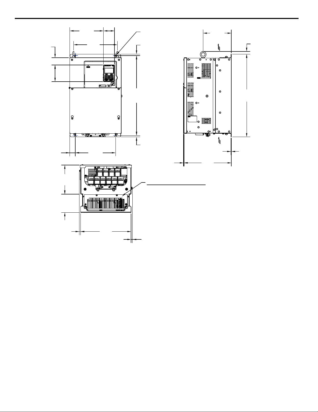
AIR
AIR
HORIZONTAL MTG DIM
VERTICAL MTG DIM
10.16
[258]
0.11
[3]
0.09
[2.3]
6.05
[153.6]
17.72
[450]
3.54
[90]
1.57
[40]
2.36
[60]
7.24
[183.9]
FRONT VIEW
(4)-MOUNTING HOLES
FOR 1/4"[M6] SCREWS
0.6
[15.2]
9.41
[239]
0.3
[7.5]
1.19
[30.1]
8.66
[220.0]
0.3
[7.5]
17.13
[435.0]
10.83
[275]
0.28
[7.1]
0.3
[7.7]
3.94
[100]
6.22
[158]
OPTIONAL CAPACITOR COVER
WHEN USING AN EXTERNAL MOUNT HEATSINK, UL COMPLIANCE
REQUIRES COVERING EXPOSED CAPACITORS IN THE MAIN
CIRCUIT TO PREVENT INJURY.
Unit: in [mm]
8 Specifications
Figure 31 Non-Flange Type Model 4T0072A Mounting Dimensions
54
YASKAWA TOEP YAIA1U 02A YASKAWA AC Drive – A1000 6-Phase/12-Pulse Input Installation Manual
Page 55
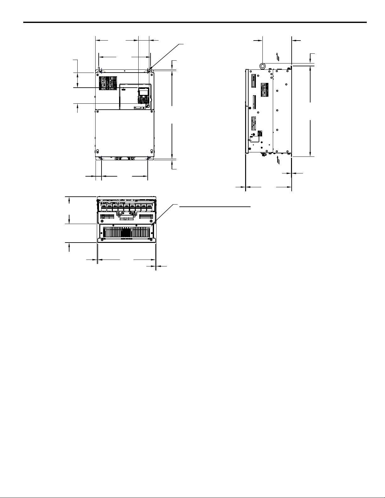
AIR
AIR
HORIZONTAL MTG DIM
VERTICAL MTG DIM
10.16
[258]
0.11
[2.7]
0.09
[2.3]
6.43
[163.3]
20.06
[509.5]
3.54
[90]
3.3
[83.8]
2.36
[60]
9.54
[242.4]
FRONT VIEW
(4)-MOUNTING HOLES
FOR 1/4"[M6] SCREWS
0.62
[15.7]
11.5
[292]
4.13
[105]
6.02
[153]
0.3
[7.5]
1.28
[32.5]
10.24
[260]
0.3
[7.5]
19.47
[494.5]
12.8
[325]
0.18
[4.6]
0.18
[4.6]
OPTIONAL CAPACITOR COVER
WHEN USING AN EXTERNAL MOUNT HEATSINK, UL COMPLIANCE
REQUIRES COVERING EXPOSED CAPACITORS IN THE MAIN
CIRCUIT TO PREVENT INJURY.
Unit: in [mm]
8 Specifications
Figure 32 Non-Flange Type Models 4T0088A and 4T0103A Mounting Dimensions
YASKAWA TOEP YAIA1U 02A YASKAWA AC Drive – A1000 6-Phase/12-Pulse Input Installation Manual
55
Page 56

AIR
AIR
HORIZONTAL MTG DIM
VERTICAL MTG DIM
11.14
[283]
0.11
[3]
0.09
[2.3]
5.22
[132.6]
21.65
[550]
3.54
[90]
9.59
[243.7]
2.36
[60]
9.31
[236.4]
FRONT VIEW
(4)-MOUNTING HOLES
0.59
[15.1]
7.75
[196.8]
4.33
[110]
6.81
[173.1]
1.26
[32]
10.24
[260]
0.3
[7.5]
0.3
[7.5]
12.76
[324]
0.31
[7.8]
0.31
[7.8]
21.06
[535]
OPTIONAL CAPACITOR COVER
WHEN USING AN EXTERNAL MOUNT HEATSINK, UL
COMPLIANCE REQUIRES COVERING EXPOSED
CAPACITORS IN THE MAIN CIRCUIT TO PREVENT INJURY.
Unit: in [mm]
8 Specifications
Figure 33 Non-Flange Type Models 4T0139A and 4T0165A Mounting Dimensions
56
YASKAWA TOEP YAIA1U 02A YASKAWA AC Drive – A1000 6-Phase/12-Pulse Input Installation Manual
Page 57

AIR
AIR
HORIZONTAL MTG DIM
VERTICAL MTG DIM
12.99
[330]
0.13
[3]
0.13
[3.2]
6
[152.5]
27.76
[705]
FRONT VIEW
(4)-MOUNTING HOLES
FOR 3/8"[M10] SCREWS
2.78
[70.5]
13.54
[343.8]
2.36
[60]
16.25
[412.7]
3.54
[90]
21.23
[539.2]
0.49
[12.5]
0.49
[12.5]
26.77
[680]
2.56
[65.1]
12.8
[325]
5.13
[130]
7.88
[200]
17.92
[455.2]
0.2
[5]
0.2
[5]
OPTIONAL CAPACITOR COVER
WHEN USING AN EXTERNAL MOUNT HEATSINK, UL
COMPLIANCE REQUIRES COVERING EXPOSED
CAPACITORS IN THE MAIN CIRCUIT TO PREVENT INJURY.
8 Specifications
Figure 34 Non-Flange Type Models 4T0208A Mounting Dimensions
YASKAWA TOEP YAIA1U 02A YASKAWA AC Drive – A1000 6-Phase/12-Pulse Input Installation Manual
57
Page 58

AIR
AIR
HORIZONTAL MTG DIM
VERTICAL MTG DIM
13.78
[350]
0.11
[3]
0.13
[3.2]
6.7
[170.1]
31.5
[800]
FRONT VIEW
(4)-MOUNTING HOLES
FOR 1/2"[M12] SCREWS
4.82
[122.5]
15.78
[400.9]
2.36
[60]
16.63
[422.3]
3.54
[90]
5.12
[130]
8.66
[220]
19.69
[500]
0.3
[8]
0.3
[8]
23.2
[589.2]
0.55
[14]
30.43
[773]
0.51
[13]
2.56
[65]
14.57
[370]
21.85
[555]
OPTIONAL CAPACITOR COVER
WHEN USING AN EXTERNAL MOUNT HEATSINK, UL
COMPLIANCE REQUIRES COVERING EXPOSED
CAPACITORS IN THE MAIN CIRCUIT TO PREVENT INJURY.
Unit: in [mm]
8 Specifications
Figure 35 Non-Flange Type Models 4T0250A to 4T0362A Mounting Dimensions
58
YASKAWA TOEP YAIA1U 02A YASKAWA AC Drive – A1000 6-Phase/12-Pulse Input Installation Manual
Page 59

AIR
AIR
HORIZONTAL MTG DIM
VERTICAL MTG DIM
14.57
[370]
0.11
[3]
0.18
[4.5]
6.84
[173.8]
40.39
[1026]
FRONT VIEW
(4)-MOUNTING HOLES
FOR 1/2"[M12] SCREWS
3.24
[82.3]
15.35
[389.9]
2.36
[60]
23.41
[594.6]
3.54
[90]
5.32
[135]
9.25
[235]
19.69
[500]
0.3
[8]
0.3
[8]
24.06
[611.2]
2.56
[65]
14.57
[370]
33.91
[861.4]
0.55
[14]
0.51
[13]
OPTIONAL CAPACITOR COVER
WHEN USING AN EXTERNAL MOUNT HEATSINK, UL
COMPLIANCE REQUIRES COVERING EXPOSED
CAPACITORS IN THE MAIN CIRCUIT TO PREVENT INJURY.
39.33
[999]
Unit: in [mm]
8 Specifications
Figure 36 Non-Flange Type Model 4T0414A Mounting Dimensions
YASKAWA TOEP YAIA1U 02A YASKAWA AC Drive – A1000 6-Phase/12-Pulse Input Installation Manual
59
Page 60

AIR
AIR
VERTICAL MTG DIM
14.57
[370]
0.15
[4]
0.18
[4.5]
7.2
[183]
50
[1270]
FRONT VIEW
(6)-MOUNTING HOLES
FOR 1/2"[M12] SCREWS
4.44
[112.7]
22.04
[559.9]
2.36
[60]
30.07
[763.9]
3.54
[90]
41.13
[1044.6]
26.38
[670]
0.24
[6]
0.24
[6]
5.91
[150]
8.66
[220]
30.76
[781.2]
4.53
[115]
8.66
[220]
8.66
[220]
HORIZONTAL MTG DIMS
0.59
[15]
0.59
[15]
OPTIONAL CAPACITOR COVER
WHEN USING AN EXTERNAL MOUNT HEATSINK, UL
COMPLIANCE REQUIRES COVERING EXPOSED
CAPACITORS IN THE MAIN CIRCUIT TO PREVENT INJURY.
48.82
[1240]
Unit: in [mm]
8 Specifications
Figure 37 Non-Flange Type Models 4T0515A and 4T6075A Mounting Dimensions
60
YASKAWA TOEP YAIA1U 02A YASKAWA AC Drive – A1000 6-Phase/12-Pulse Input Installation Manual
Page 61
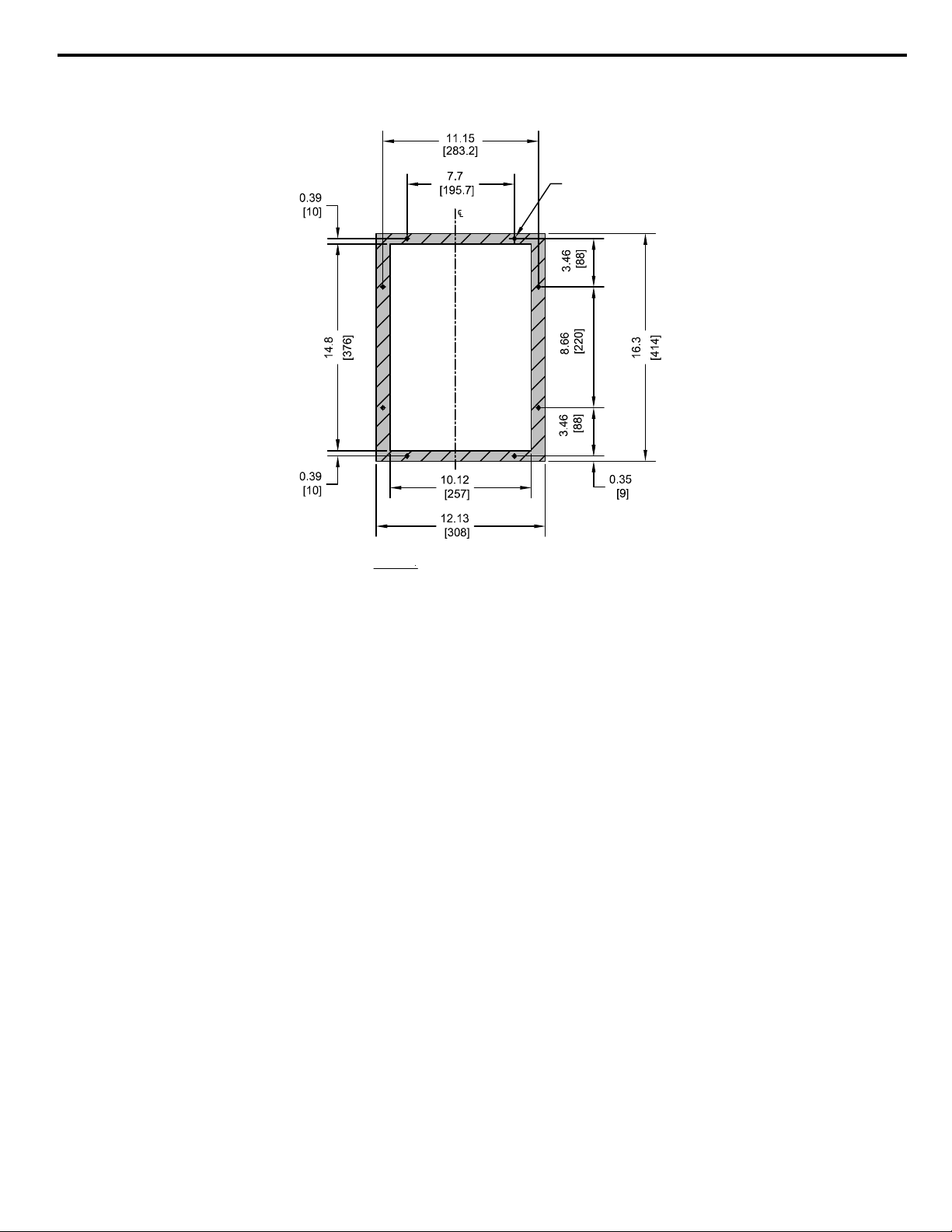
Panel Cutout Dimensions
CUTOUT
NOTES:
1. CUTOUT TOLERANCES:
+/- 0.02 in. [0.5 mm]
2. EXPOSED HEATSINK DEPTH
3. MINIMUM RECOMMENDED PANEL
THICKNESS: 12 GA
D=3.82 in. [97 mm] MINUS PANEL THICKNESS
(8)-1/4 in. [M6]
THREADED HOLES
Unit: in. [mm]
n
Panel Cutout Dimensions for Flange Type 4TooooU Models
8 Specifications
Figure 38 Flange Type Model 4T0058U Panel Cutout Dimensions
YASKAWA TOEP YAIA1U 02A YASKAWA AC Drive – A1000 6-Phase/12-Pulse Input Installation Manual
61
Page 62

CUTOUT
NOTES:
1. CUTOUT TOLERANCES:
+/- 0.02 in. [0.5 mm]
2. EXPOSED HEATSINK DEPTH
3. MINIMUM RECOMMENDED PANEL
THICKNESS: 12 GA
D=3.81 in. [97 mm] MINUS PANEL THICKNESS
(8)-1/4 in. [M6]
THREADED HOLES
Unit: in. [mm]
8 Specifications
Figure 39 Flange Type Model 4T0072U Panel Cutout Dimensions
62
YASKAWA TOEP YAIA1U 02A YASKAWA AC Drive – A1000 6-Phase/12-Pulse Input Installation Manual
Page 63

CUTOUT
Unit: in. [mm]
NOTES:
1. CUTOUT TOLERANCES:
+/- 0.02 in. [0.5 mm]
2. EXPOSED HEATSINK DEPTH
3. MINIMUM RECOMMENDED PANEL
THICKNESS: 12 GA
D=3.97 in. [101 mm] MINUS PANEL THICKNESS
(12)-1/4 in. [M6]
THREADED HOLES
8 Specifications
Figure 40 Flange Type Models 4T0088U and 4T0103U Panel Cutout Dimensions
YASKAWA TOEP YAIA1U 02A YASKAWA AC Drive – A1000 6-Phase/12-Pulse Input Installation Manual
63
Page 64

CUTOUT
NOTES:
1. CUTOUT TOLERANCES:
+/- 0.02 in. [0.5 mm]
2. EXPOSED HEATSINK DEPTH
3. MINIMUM RECOMMENDED PANEL
THICKNESS: 12 GA
D=4.21 in. [107 mm] MINUS PANEL THICKNESS
Unit: in. [mm]
(12)-1/4 in. [M6]
THREADED HOLES
8 Specifications
Figure 41 Flange Type Models 4T0139U and 4T0165U Panel Cutout Dimensions
64
YASKAWA TOEP YAIA1U 02A YASKAWA AC Drive – A1000 6-Phase/12-Pulse Input Installation Manual
Page 65

NOTES:
+/- 0.02 in. [0.5 mm]
2. EXPOSED HEATSINK DEPTH
3. MINIMUM RECOMMENDED PANEL
THICKNESS: 10 GA
D=5.00 in. [127 mm] MINUS PANEL THICKNESS
(13)-3/8 in. [M10]
THREADED HOLES
Unit: in. [mm]
CUTOUT
1. CUTOUT TOLERANCES:
8 Specifications
Figure 42 Flange Type Model 4T0208U Panel Cutout Dimensions
YASKAWA TOEP YAIA1U 02A YASKAWA AC Drive – A1000 6-Phase/12-Pulse Input Installation Manual
65
Page 66

Unit: in. [mm]
NOTES:
1. CUTOUT TOLERANCES:
+/- 0.02 in. [0.5 mm]
2. EXPOSED HEATSINK DEPTH
3. MINIMUM RECOMMENDED PANEL
THICKNESS: 10 GA
D=4.99 in. [127 mm] MINUS PANEL THICKNESS
CUTOUT
(13)-3/8 in. [M10]
THREADED HOLES
8 Specifications
Figure 43 Flange Type Models 4T0250U to 4T0362U Panel Cutout Dimensions
66
YASKAWA TOEP YAIA1U 02A YASKAWA AC Drive – A1000 6-Phase/12-Pulse Input Installation Manual
Page 67

CUTOUT
Unit: in. [mm]
NOTES:
1. CUTOUT TOLERANCES:
+/- 0.02 in. [0.5 mm]
2. EXPOSED HEATSINK DEPTH
3. MINIMUM RECOMMENDED PANEL
THICKNESS: 10 GA
D=5.19 in. [132 mm] MINUS PANEL THICKNESS
(20)-3/8 in. [M10]
THREADED HOLES
8 Specifications
Figure 44 Flange Type Model 4T0414U Panel Cutout Dimensions
YASKAWA TOEP YAIA1U 02A YASKAWA AC Drive – A1000 6-Phase/12-Pulse Input Installation Manual
67
Page 68

CUTOUT
NOTES:
1. CUTOUT TOLERANCES:
+/- 0.02 in. [0.5 mm]
2. EXPOSED HEATSINK DEPTH
3. MINIMUM RECOMMENDED PANEL
THICKNESS: 10 GA
D=7.71 in. [196 mm] MINUS PANEL THICKNESS
(20)-3/8 in. [M10]
THREADED HOLES
Unit: in. [mm]
8 Specifications
Figure 45 Flange Type Models 4T0515U and 4T0675U Panel Cutout Dimensions
68
YASKAWA TOEP YAIA1U 02A YASKAWA AC Drive – A1000 6-Phase/12-Pulse Input Installation Manual
Page 69

Panel Cutout Dimensions for Non-Flange Type 4TooooA Models
1.97
[50]
1.97
[50]
4.72
[120]
4.72
[120]
1.18
[30]
1.18
[30]
(4)-1/4"
[M6]
NOTE:
EXPOSED HEATSINK DEPTH
D=3.94" MINUS PANEL THICKNESS
AIR
AIR
15.16±.02 [385±0.5]
15.75±.02 [400±0.5]
7.68±.02 [195±0.5]
9.84±.02 [250±0.5]
14.53±.02 [369±0.5]
9.21±.02 [234±0.5]
CUTOUT
0.31
[8]
0.31
[8]
0.3
[7.5]
℄
AIR
AIR
Unit: in. [mm]
8 Specifications
Figure 46 Non-Flange Type Model 4T0058A Clearances and Panel Cutout Dimensions
YASKAWA TOEP YAIA1U 02A YASKAWA AC Drive – A1000 6-Phase/12-Pulse Input Installation Manual
69
Page 70

1.97
[50]
1.97
[49.9]
4.72
[120]
4.72
[120]
1.18
[30]
1.18
[30]
(4)-1/4"
[M6]
AIR
AIR
AIR
AIR
17.13±.02 [435±0.5]
17.72±.02 [450±0.5]
8.66±.02 [220±0.5]
10.83±.02 [275±0.5]
16.5±.02 [419±0.5]
10.2±.02 [259±0.5]
CUTOUT
0.31
[8]
0.31
[8]
0.3
[7.5]
℄
NOTE:
EXPOSED HEATSINK DEPTH
D=3.94" MINUS PANEL THICKNESS
Unit: in. [mm]
8 Specifications
70
Figure 47 Non-Flange Type Model 4T0072A Clearances and Panel Cutout Dimensions
YASKAWA TOEP YAIA1U 02A YASKAWA AC Drive – A1000 6-Phase/12-Pulse Input Installation Manual
Page 71

1.97
[50]
1.97
[50]
4.72
[120]
4.72
[120]
1.18
[30]
1.18
[30]
(4)-1/4"
[M6]
AIR
AIR
19.49±.02 [495±0.5]
20.08±.02 [510±0.5]
10.24±.02 [260±0.5]
12.8±.02 [325±0.5]
18.86±.02 [479±0.5]
12.17±.02 [309±0.5]
CUTOUT
0.31
[8]
0.31
[8]
0.3
[7.5]
NOTE:
EXPOSED HEATSINK DEPTH
D=4.13" MINUS PANEL THICKNESS
AIR
AIR
℄
Unit: in. [mm]
8 Specifications
Figure 48 Non-Flange Type Models 4T0088A and 4T0103A Clearances and Panel Cutout Dimensions
YASKAWA TOEP YAIA1U 02A YASKAWA AC Drive – A1000 6-Phase/12-Pulse Input Installation Manual
71
Page 72

1.97
[50]
1.97
[50]
4.72
[120]
4.72
[120]
1.18
[30]
1.18
[30]
(4)-1/4"
[M6]
AIR
AIR
21.06±.02 [535±0.5]
21.65±.02 [550±0.5]
10.24±.02 [260±0.5]
12.8±.02 [325±0.5]
20.43±.02 [519±0.5]
12.17±.02 [309±0.5]
CUTOUT
0.31
[8]
0.31
[8]
0.3
[7.5]
NOTE:
EXPOSED HEATSINK DEPTH
D=4.33" MINUS PANEL THICKNESS
℄
AIR
AIR
Unit: in. [mm]
8 Specifications
72
Figure 49 Non-Flange Type Models 4T0139A and 4T0165A Clearances and Panel Cutout Dimensions
YASKAWA TOEP YAIA1U 02A YASKAWA AC Drive – A1000 6-Phase/12-Pulse Input Installation Manual
Page 73

1.97
[50]
1.97
[50]
4.72
[120]
4.72
[120]
1.18
[30]
1.18
[30]
(4)-3/8"
[M10]
AIR
AIR
26.77±.02 [680±0.5]
27.76±.02 [705±0.5]
12.8±.02 [325±0.5]
17.72±.02 [450±0.5]
25.79±.02 [655±0.5]
17.09±.02 [434±0.5]
CUTOUT
0.49
[12.5]
0.49
[12.5]
0.49
[12.5]
NOTE:
EXPOSED HEATSINK DEPTH
D=5.12" MINUS PANEL THICKNESS
℄
AIR
AIR
Unit: in. [mm]
8 Specifications
Figure 50 Flange Type Model 4T0208A Clearances and Panel Cutout Dimensions
YASKAWA TOEP YAIA1U 02A YASKAWA AC Drive – A1000 6-Phase/12-Pulse Input Installation Manual
73
Page 74

1.97
[50]
1.97
[50]
4.72
[120]
4.72
[120]
1.18
[30]
1.18
[30]
(4)-1/2"
[M12]
AIR
AIR
AIR
AIR
30.43±.02 [773±0.5]
31.5±.02 [800±0.5]
14.57±.02 [370±0.5]
19.69±.02 [500±0.5]
29.13±.02 [740±0.5]
19.06±.02 [484±0.5]
CUTOUT
0.63
[16]
0.67
[17]
0.51
[13]
NOTE:
EXPOSED HEATSINK DEPTH
D=5.12" MINUS PANEL THICKNESS
0.55
[14]
℄
Unit: in. [mm]
8 Specifications
Figure 51 Non-Flange Type Models 4T0250A to 4T0362A Clearances and Panel Cutout Dimensions
74
YASKAWA TOEP YAIA1U 02A YASKAWA AC Drive – A1000 6-Phase/12-Pulse Input Installation Manual
Page 75

1.97
[50]
1.97
[50]
4.72
[120]
4.72
[120]
1.18
[30]
1.18
[30]
(4)-1/2"
[M12]
AIR
AIR
39.33±.02 [999±0.5]
40.39±.02 [1026±0.5]
14.57±.02 [370±0.5]
19.69±.02 [500±0.5]
38.03±.02 [966±0.5]
19.06±.02 [484±0.5]
CUTOUT
0.63
[16]
0.69
[17.5]
0.51
[13]
NOTE:
EXPOSED HEATSINK DEPTH
D=5.32" MINUS PANEL THICKNESS
0.55
[14]
AIR
AIR
℄
Unit: in. [mm]
8 Specifications
Figure 52 Non-Flange Type Model 4T0414A Clearances and Panel Cutout Dimensions
YASKAWA TOEP YAIA1U 02A YASKAWA AC Drive – A1000 6-Phase/12-Pulse Input Installation Manual
75
Page 76

(6)-1/2"
[M12]
17.32±.02 [440±0.5]
26.38±.02 [670±0.5]
47.32±.02 [1202±0.5]
CUTOUT
0.75
[19]
0.75
[19]
0.59
[15]
NOTE:
EXPOSED HEATSINK DEPTH
D=5.91" MINUS PANEL THICKNESS
1.97
[50]
1.97
[50]
4.72
[120]
4.72
[120]
1.18
[30]
1.18
[30]
AIR
AIR
AIR
AIR
48.82±.02 [1240±0.5]
50±.02 [1270±0.5]
25.75±.02 [654±0.5]
0.59
[15]
℄
Unit: in. [mm]
8 Specifications
Figure 53 Non-Flange Type Models 4T0515A and 4T0675A Clearances and Panel Cutout Dimensions
76
YASKAWA TOEP YAIA1U 02A YASKAWA AC Drive – A1000 6-Phase/12-Pulse Input Installation Manual
Page 77

9 Parameter Table
9 Parameter Table
This parameter table shows the most important parameters. Default settings are in bold type. Refer to the drive Technical
Manual for a complete list of parameters.
No. Name Description
0: V/f Control
1: V/f Control with PG
2: Open Loop Vector Control
A1-02
Control Method
Selection
3: Closed Loop Vector Control
5: Open Loop Vector Control for PM
6: Advanced Open Loop Vector Control for
PM
7: Closed Loop Vector Control for PM
0: No initialization
1110: User Initialize (parameter values
A1-03 Initialize Parameters
must be stored using parameter o2-03)
2220: 2-Wire initialization
3330: 3-Wire initialization
5550: oPE04 error reset
0: General-purpose
1: Water supply pump
A1-06 Application Preset
2: Conveyor
3: Exhaust fan
4: HVAC fan
5: Air compressor
0: Digital operator
b1-01
Frequency Reference
Selection 1
1: Analog input terminals
2: MEMOBUS/Modbus communications
3: Option PCB
4: Pulse train input (terminal RP)
0: Digital operator
b1-02
Run Command
Selection 1
1: Digital input terminals
2: MEMOBUS/Modbus communications
3: Option PCB
0: Ramp to stop
b1-03
Stopping Method
Selection
1: Coast to stop
2: DC Injection Braking to stop
3: Coast with timer
b1-04
Reverse Operation
Selection
C1-01 Acceleration Time 1
C1-02 Deceleration Time 1
C2-01
C2-02
C2-03
C2-04
S-Curve Characteristic
at Accel Start
S-Curve Characteristic
at Accel End
S-Curve Characteristic
at Decel Start
S-Curve Characteristic
at Decel End
0: Reverse enabled.
1: Reverse disabled.
Sets the time to accelerate from 0 to
maximum frequency.
Sets the time to decelerate from maximum
frequency to 0.
S-curve at acceleration start.
S-curve at acceleration end.
S-curve at deceleration start.
S-curve at deceleration end.
0: Heavy Duty (HD)
Overload capability: 150% of drive rated
Heavy Duty current for 60 s
Default Carrier Frequency: 2 kHz
C6-01 Drive Duty Selection
1: Normal Duty (ND)
Overload capability: 120% of drive rated
Normal Duty current for 60 s
Default Carrier Frequency: 2 kHz Swing
PWM
No. Name Description
1: 4.0 kHz
2: 6.0 kHz
3: 8.0 kHz
4: 10.0 kHz
C6-02
Carrier Frequency
Selection
F: User-defined (determined by C6-03 to
C6-05)
Default setting value is determined by
A1-02, Control Method Selection, C6-01,
Drive Duty Selection, and o2-04, Drive
Model Selection.
d1-01 to
d1-16
d1-17
d2-01
d2-02
Frequency Reference 1
to 16
Jog Frequency
Reference
Frequency Reference
Upper Limit
Frequency Reference
Lower Limit
Sets the frequency reference for the drive.
Setting units are determined by parameter
o1-03.
Sets the Jog frequency reference. Setting
units are determined by parameter o1-03.
Sets the frequency reference upper limit as
a percentage of the maximum output
frequency.
Sets the frequency reference lower limit as
a percentage of the maximum output
frequency.
0: 50 Hz, Constant torque 1
1: 60 Hz, Constant torque 2
2: 60 Hz, Constant torque 3 (50 Hz base)
3: 72 Hz, Constant torque 4 (60 Hz base)
4: 50 Hz, Variable torque 1
5: 50 Hz, Variable torque 2
6: 60 Hz, Variable torque 1
7: 60 Hz, Variable torque 2
E1-03 V/f Pattern Selection
8: 50 Hz, High starting torque 1
9: 50 Hz, High starting torque 2
A: 60 Hz, High starting torque 3
B: 60 Hz, High starting torque 4
C: 90 Hz (60 Hz base)
D: 120 Hz (60 Hz base)
E: 180 Hz (60 Hz base)
F: Custom V/f, E1-04 through E1-13
settings define the V/f pattern
E1-04
Maximum Output
Frequency
E1-05 Maximum Voltage
E1-06 Base Frequency
E1-07
E1-08
E1-09
E1-10
E1-11
E1-12
Middle Output
Frequency
Middle Output
Frequency Voltage
Minimum Output
Frequency
Minimum Output
Frequency Voltage
Middle Output
Frequency 2
Middle Output
Frequency Voltage 2
E1-13 Base Voltage
Parameters E1-04 and E1-06 to E1-13 can
only be changed when E1-03 is set to F.
To set linear V/f characteristics, set the
same values for E1-07 and E1-09.
In this case, the setting for E1-08 will be
disregarded. Ensure that the five
frequencies are set according to the
following rules to prevent triggering an
oPE10 fault:
E1-09 ≤ E1-07 < E1-06 ≤ E1-11 ≤ E1-04
Setting E1-11 to 0 disables both E1-11 and
E1-12 and the above conditions do not
apply.
Output Voltage (V)
E1-05
E1-12
E1-13
E1-08
E1-10
E1-09 E1-07 E1-06 E1-11 E1-04
Frequency (Hz)
E2-01 Motor Rated Current
YASKAWA TOEP YAIA1U 02A YASKAWA AC Drive – A1000 6-Phase/12-Pulse Input Installation Manual
Sets the motor nameplate full load current
in amps. Automatically set during
Auto-Tuning.
77
Page 78

9 Parameter Table
No. Name Description
H1-01 to
H1-08
H2-01
H2-02
H2-03
H2-06
H2-07
H2-08
H2-09
H2-10
H3-01
H3-02
H3-03
H3-04
H3-05
H3-06
H3-07
H3-08
H3-09
Multi-Function Digital
Input Terminal S1 to
S8 Function Selection
Multi-Function
Contact Output
(terminal M1-M2)
Multi-Function
Contact Output 2
(terminal M3-M4)
Terminal M5-M6
function selection
(relay)
Power Consumption
Output Unit Selection
MEMOBUS Register 1
Address Select
MEMOBUS Register 1
Bit Select
MEMOBUS Register 2
Address Select
MEMOBUS Register 2
Bit Select
Terminal A1 Signal
Level Selection
Terminal A1 Function
Selection
Terminal A1 Gain
Setting
Terminal A1 Bias
Setting
Terminal A3 Signal
Level Selection
Terminal A3 Function
Selection
Terminal A3 Gain
Setting
Terminal A3 Bias
Setting
Terminal A2 Signal
Level Selection
Selects the function of terminals S1 to S8.
Sets the function for the relay output
M1-M2.
Sets the function for the relay output
M3-M4.
Sets the function for the relay output
M5-M6
0: 0.1 kWh units
1: 1 kWh units
2: 10 kWh units
3: 100 kWh units
4: 1000 kWh units
Sets the addresses of the MEMOBUS/
Modbus registers from which data will be
sent to contact outputs 62 and 162.
Sets the bits for the MEMOBUS/Modbus
registers from which data will be sent to
contact outputs 62 and 162.
Sets the addresses of the MEMOBUS/
Modbus registers from which data will be
sent to contact outputs 63 and 163.
Sets the bits for the MEMOBUS/Modbus
registers from which data will be sent to
contact outputs 63 and 163.
0: 0 to 10 V
1: -10 to 10 V
Sets the function of terminal A1.
Sets the level of the input value selected in
H3-02 when 10 V is input at terminal A1.
Sets the level of the input value selected in
H3-02 when 0 V is input at terminal A1.
0: 0 to 10 V
1: -10 to 10 V
Sets the function of terminal A3.
Sets the level of the input value selected in
H3-06 when 10 V is input at terminal A3.
Sets the level of the input value selected in
H3-06 when 0 V is input at terminal A3.
0: 0 to 10 V
1: -10 to 10 V
2: 4 to 20 mA
3: 0 to 20 mA
Note: Use DIP switch S1 to set
input terminal A2 for a
current or a voltage input
signal.
H3-10
H3-11
H3-12
H3-13
Terminal A2 Function
Selection
Terminal A2 Gain
Setting
Terminal A2 Bias
Setting
Analog Input Filter
Time Constant
Sets the function of terminal A2.
Sets the level of the input value selected in
H3-10 when 10 V (20 mA) is input at
terminal A2.
Sets the level of the input value selected in
H3-10 when 0 V (0 or 4 mA) is input at
terminal A2.
Sets a primary delay filter time constant for
terminals A1, A2, and A3. Used for noise
filtering.
No. Name Description
1: Terminal A1 only
2: Terminal A2 only
H3-14
H3-16 Terminal A1 Offset
H3-17 Terminal A2 Offset
H3-18 Terminal A3 Offset
H4-01
H4-02
H4-03
H4-04
H4-05
H4-06
H4-07
H4-08
H5-01 Drive Node Address
H5-02
H5-03
H5-04
H5-05
H5-06
Analog Input Terminal
Enable Selection
Multi-Function Analog
Output Terminal FM
Monitor Selection
Multi-Function Analog
Output Terminal FM
Gain
Multi-Function Analog
Output Terminal FM
Bias
Multi-Function Analog
Output Terminal AM
Monitor Selection
Multi-Function Analog
Output Terminal AM
Gain
Multi-Function Analog
Output Terminal AM
Bias
Multi-Function Analog
Output Terminal FM
Signal Level Selection
Multi-Function Analog
Output Terminal AM
Signal Level Selection
Communication Speed
Selection
Communication Parity
Selection
Stopping Method After
Communication Error
(CE)
Communication Fault
Detection Selection
Drive Transmit Wait
Time
3: Terminals A1 and A2 only
4: Terminal A3 only
5: Terminals A1 and A3
6: Terminals A2 and A3
7: All terminals enabled
Adds an offset when the analog signal to
terminal A1 is at 0 V.
Adds an offset when the analog signal to
terminal A2 is at 0 V.
Adds an offset when the analog signal to
terminal A3 is at 0 V.
Selects the data to be output through multifunction analog output terminal FM.
Set the desired monitor parameter to the
digits available in Uo-oo.
For example, enter “103” for U1-03.
Sets the signal level at terminal FM that is
equal to 100% of the selected monitor
value.
Sets the signal level at terminal FM that is
equal to 0% of the selected monitor value.
Selects the data to be output through multifunction analog output terminal AM.
Set the desired monitor parameter to the
digits available in Uo-oo.
For example, enter “103” for U1-03.
Sets the signal level at terminal AM that is
equal to 100% of the selected monitor
value.
Sets the signal level at terminal AM that is
equal to 0% of the selected monitor value.
0: 0 to 10 V
1: -10 to 10 V
2: 4 to 20mA
0: 0 to 10 V
1: -10 to 10 V
2: 4 to 20 mA
Selects drive station node number (address)
for MEMOBUS/Modbus terminals R+, R-,
S+, S-. Cycle power for the setting to take
effect.
0: 1200 bps
1: 2400 bps
2: 4800 bps
3: 9600 bps
4: 19200 bps
5: 38400 bps
6: 57600 bps
7: 76800 bps
8: 115200 bps
Cycle power for the setting to take effect.
0: No parity
1: Even parity
2: Odd parity
Cycle power for the setting to take effect.
0: Ramp to stop
1: Coast to stop
2: Fast Stop
3: Alarm only
0: Disabled
1: Enabled. If communication is lost for
more than two seconds, a CE fault will
occur.
Set the wait time between receiving and
sending data.
78
YASKAWA TOEP YAIA1U 02A YASKAWA AC Drive – A1000 6-Phase/12-Pulse Input Installation Manual
Page 79

9 Parameter Table
No. Name Description
H5-07 RTS Control Selection
H5-09
H5-10
H5-11
H5-12
H6-01
H6-02
H6-03 Pulse Train Input Gain
H6-04 Pulse Train Input Bias
H6-05
H6-06
H6-07
H6-08
L1-01
L1-02
L2-01
Communication Fault
Detection Time
Unit Selection for
MEMOBUS/Modbus
Register 0025H
Communications
ENTER Function
Selection
Run Command
Method Selection
Pulse Train Input
Terminal RP Function
Selection
Pulse Train Input
Scaling
Pulse Train Input Filter
Time
Pulse Train Monitor
Selection
Pulse Train Monitor
Scaling
Pulse Train Input
Minimum Frequency
Motor Overload
Protection Selection
Motor Overload
Protection Time
Momentary Power
Loss Operation
Selection
0: Disabled. RTS is always on.
1: Enabled. RTS turns on only when
sending.
Sets the time required to detect a
communications error.
0: 0.1 V units
1: 1 V units
0: Drive requires an Enter command
before accepting any changes to
parameter settings.
1: Parameter changes are activated
immediately without the Enter command.
0: FWD/Stop, REV/Stop
1: Run/Stop, FWD/REV
0: Frequency reference
1: PID feedback value
2: PID setpoint value
3: V/f Control with Simple PG feedback
(possible only when using motor 1 in V/f
Control)
Sets the terminal RP input signal frequency
that is equal to 100% of the value selected
in H6-01.
Sets the level of the value selected in H6-01
when a frequency with the value set in
H6-02 is input.
Sets the level of the value selected in H6-01
when 0 Hz is input.
Sets the pulse train input filter time
constant.
Select the pulse train monitor output
function (value of the o-oo part of
Uo-oo).
For example, enter “501” for U5-01.
Sets the terminal MP output signal
frequency when the monitor value is 100%.
For example, to have the pulse train monitor
output equal the output frequency, set
H6-06 to 102 and H6-07 to 0.
Sets the minimum frequency for the pulse
train input to be detected. Enabled when
H6-01 = 0, 1, or 2.
0: Disabled
1: General purpose motor (standard fan
cooled)
2: Drive dedicated motor with a speed range
of 1:10
3: Vector motor with a speed range of 1:100
4: PM motor with variable torque
5: PM motor with constant torque control
6: General purpose motor (50 Hz)
Default setting is determined by parameter
A1-02, Control Method Selection.
Sets the motor thermal overload protection
(oL1) time.
0: Disabled. Drive trips on Uv1 fault
when power is lost.
1: Recover within the time set in L2-02. Uv1
will be detected if power loss is longer than
L2-02.
2: Recover as long as CPU has power. Uv1
is not detected.
3: KEB deceleration for the time set to
L2-02.
4: KEB deceleration as long as CPU has
power.
5: KEB deceleration to stop.
No. Name Description
0: Disabled. Deceleration at the active
deceleration rate. An ov fault may occur.
1: General purpose. Deceleration is
paused when the DC bus voltage exceeds
the Stall Prevention level.
2: Intelligent. Decelerate as fast as possible
while avoiding ov faults.
3: Stall Prevention with braking resistor.
Stall Prevention during deceleration is
enabled in coordination with dynamic
braking.
4: Overexcitation Deceleration.
Decelerates while increasing the motor
flux.
5: Overexcitation Deceleration 2. Adjust
the deceleration rate according to the DC
voltage.
Sets the number of times the drive may
attempt to restart after the following faults
occur: GF, LF, oC, oH1, oL1, oL3, oL4, ov,
Sto, Uv1.
0: Disabled
1: oL3 detection only active during speed
agree, operation continues after detection
2: oL3 detection always active during run,
operation continues after detection
3: oL3 detection only active during speed
agree, output shuts down on an oL3 fault
4: oL3 detection always active during run,
output shuts down on an oL3 fault
5: UL3 detection only active during speed
agree, operation continues after detection
6: UL3 detection always active during run,
operation continues after detection
7: UL3 detection only active during speed
agree, output shuts down on a UL3 fault
8: UL3 detection always active during run,
output shuts down on a UL3 fault
Sets the overtorque and undertorque
detection level.
Sets the time an overtorque or undertorque
condition must exist to trigger torque
detection 1.
0: Resistor overheat protection disabled
1: Resistor overheat protection enabled
An overheat alarm occurs when heatsink
temperature exceeds the L8-02 level.
0: Ramp to stop. A fault is triggered.
1: Coast to stop. A fault is triggered.
2: Fast Stop. Decelerate to stop using the
deceleration time in C1-09. A fault is
triggered.
3: Continue operation. An alarm is
triggered.
4: Continue operation at reduced speed as
set in L8-19.
Selects the detection of input current phase
loss, power supply voltage imbalance, or
main circuit electrolytic capacitor
deterioration.
0: Disabled
1: Enabled
0: Disabled
1: Enabled (triggered by a single phase
loss)
2: Enabled (triggered when two phases are
lost)
0: Disabled
1: Enabled
Default setting is determined by parameters
C6-01, Drive Duty Selection, and o2-04,
Drive Model Selection.
L3-04
L5-01
L6-01
L6-02
L6-03
L8-01
L8-02
L8-03
(04AF)
L8-05
(04B1)
L8-07
(04B3)
L8-09
(04B5)
Stall Prevention
Selection during
Deceleration
Number of Auto
Restart Attempts
Torque Detection
Selection 1
Torque Detection
Level 1
Torque Detection Time
1
Internal Dynamic
Braking Resistor
Protection Selection
(ERF type)
Overheat Alarm
Level
Overheat Pre-Alarm
Operation Selection
Input Phase Loss
Protection Selection
Output Phase Loss
Protection Selection
Output Ground Fault
Detection Selection
YASKAWA TOEP YAIA1U 02A YASKAWA AC Drive – A1000 6-Phase/12-Pulse Input Installation Manual
79
Page 80

9 Parameter Table
No. Name Description
0: Run with timer (Fan operates only
L8-10
(04B6)
L8-11
(04B7)
L8-12
(04B8)
L8-15
(04BB)
L8-18
(04BE)
L8-19
(04BF)
L8-27
(04DD)
L8-29
(04DF)
L8-32
(04E2)
L8-35
(04EC)
L8-38
(04EF)
Heatsink Cooling Fan
Operation Selection
Heatsink Cooling Fan
Off Delay Time
Ambient Temperature
Setting
oL2 Characteristics
Selection at Low
Speeds
Software Current Limit
Selection
Frequency Reduction
Rate during Overheat
Pre-Alarm
Overcurrent Detection
Gain
Current Unbalance
Detection (LF2)
Cooling Fan Failure
Selection
Installation Method
Selection
Carrier Frequency
Reduction
during run and for L8-11 seconds after
stop.)
1: Run always (Cooling fan operates
whenever the drive is powered up.)
Sets a delay time to shut off the cooling fan
after the Run command is removed when
L8-10 = 0.
Enter the ambient temperature. This value
adjusts the oL2 detection level.
0: No oL2 level reduction below 6 Hz.
1: oL2 level is reduced linearly below 6
Hz. It is halved at 0 Hz.
0: Disabled
1: Enabled
Specifies the frequency reference reduction
gain at overheat pre-alarm when L8-03 = 4.
Sets the gain for overcurrent detection as a
percentage of the motor rated current.
Overcurrent is detected using the lower
value between the overcurrent level of the
drive or the value set to L8-27.
0: Disabled
1: Enabled (current and voltage
detection)
2: Enabled (current detection)
3: Enabled (voltage detection)
Determines drive response when a fault
occurs with the internal cooling fan.
0: Ramp to stop
1: Coast to stop
2: Fast stop (Decelerate to stop using the
deceleration time set to C1-09)
3: Alarm only (“FAn” will flash)
4: Continue operation at reduced speed as
set to L8-19.
0: IP00/Open-Chassis enclosure
1: Side-by-Side mounting
2: IP20/NEMA Type 1 enclosure
3: Finless model drive or external heatsink
installation
Set this parameter to 3 for all 6-Phase/12Pulse Flange and Non-Flange models.
0: Disabled
1: Enabled below 6 Hz
2: Enabled for the entire speed range
Default setting is determined by parameters
A1-02, Control Method Selection, and
o2-04, Drive Model Selection.
No. Name Description
Sets the time that the drive continues
running with reduced carrier frequency
after the carrier reduction condition is gone.
Setting 0.00 s disables the carrier frequency
reduction time.
0: Disabled
1: Enabled. An alarm is triggered at output
currents above 150% of drive rated current.
0: Disabled. Disable when using a regen
converter or optional braking unit.
1: Protection enabled.
Enables motor protection in the event of
output phase loss.
0: Disabled
1: Enabled
Sets the amount of time until baseblock is
executed after detecting pull-out at low
speed.
Determines the detection level of pull-out
at low speed.
Sets the average number of times pull-out
can occur at low speed.
0: 0.01 Hz
1: 0.01% (100% = E1-04)
2: r/min (calculated using the number of
motor poles setting in E2-04, E4-04, or
E5-04)
3: User-selected units (set by o1-10 and
o1-11)
Default setting is determined by parameter
A1-02, Control Method Selection.
0: Rotational Auto-Tuning
1: Stationary Auto-Tuning 1
2: Stationary Auto-Tuning for Line-to-Line
Resistance
3: Rotational Auto-Tuning for V/f Control
(necessary for Energy Savings and Speed
Estimation Speed Search)
4: Stationary Auto-Tuning 2
5: Stationary Auto-Tuning 3
8: Inertia Tuning (perform Rotational AutoTuning prior to Inertia Tuning)
9: ASR Gain Tuning (perform Rotational
Auto-Tuning prior to ASR Gain AutoTuning)
L8-40
(04F1)
L8-41
(04F2)
L8-55
(045F)
L8-78
(02CC)
L8-93
(073C)
L8-94
(073D)
L8-95
(073F)
o1-03
T1-01
Carrier Frequency
Reduction Off Delay
Time
High Current Alarm
Selection
Internal Braking
Transistor Protection
Power Unit Output
Phase Loss Protection
LSo Detection Time at
Low Speed
LSo Detection Level at
Low Speed
Average LSo
Frequency at Low
Speed
Digital Operator
Display Selection
Auto-Tuning Mode
Selection
80
YASKAWA TOEP YAIA1U 02A YASKAWA AC Drive – A1000 6-Phase/12-Pulse Input Installation Manual
Page 81

10 Standards Compliance
10 Standards Compliance
u
European Standards
Figure 54 CE Mark
The CE mark indicates compliance with European safety and environmental regulations. It is required for engaging in business
and commerce in Europe.
European standards include the Machinery Directive for machine manufacturers, the Low Voltage Directive for electronics
manufacturers, and the EMC guidelines for controlling noise.
This drive displays the CE mark based on the EMC guidelines and the Low Voltage Directive.
• Low Voltage Directive: 2006/95/EC
• EMC Guidelines: 2004/108/EC
Devices used in combination with this drive must also be CE certified and display the CE mark. When using drives displaying
the CE mark in combination with other devices, it is ultimately the responsibility of the user to ensure compliance with CE
standards. After setting up the device, verify that conditions meet European standards.
u
CE Low Voltage Directive Compliance
This drive has been tested according to European standard IEC/EN 61800-5-1, and it fully complies with the Low Voltage
Directive.
To comply with the Low Voltage Directive, be sure to meet the following conditions when combining this drive with other
devices:
Area of Use
n
Do not use drives in areas with pollution higher than degree 2 and overvoltage category 3 in accordance with IEC/EN 664.
Grounding
n
The drive is designed to be used in T-N (grounded neutral point) networks. If installing the drive in other types of grounded
systems, contact your Yaskawa representative for instructions.
Guarding Against Harmful Materials
n
When installing IP00/Open Type enclosure drives, use an enclosure that prevents foreign material from entering the drive
from above or below.
u
EMC Guidelines Compliance
This drive is tested according to European standards IEC/EN 61800-3: 2004.
EMC Filter Installation
n
The following conditions must be met to ensure continued compliance with guidelines. Refer to EMC Filters on page 84
for EMC filter selection.
Installation Method
Verify the following installation conditions to ensure that other devices and machinery used in combination with this drive
also comply with EMC guidelines.
Install an EMC noise filter to the input side specified by Yaskawa for compliance with European standards.
1.
Place the drive and EMC noise filter in the same enclosure.
2.
Use braided shield cable for the drive and motor wiring, or run the wiring through a metal conduit.
3.
Keep wiring as short as possible. Ground the shield on both the drive side and the motor side.
4.
YASKAWA TOEP YAIA1U 02A YASKAWA AC Drive – A1000 6-Phase/12-Pulse Input Installation Manual
81
Page 82

10 Standards Compliance
B
A
U/T1
V/T2
W/T3
D
C
U
V
M
W
E
A – Drive
B – 10 m max cable length between
drive and motor
D – Metal conduit
E – Ground wire should be as short as
possible.
C – Motor
Figure 55 Installation Method
Make sure the protective earthing conductor complies with technical standards and local safety regulations.
5.
A
C
A – Braided shield cable
B
C – Cable clamp (conductive)
B – Metal panel
Figure 56 Ground Area
Connect a DC link choke to minimize harmonic distortion.
6.
82
YASKAWA TOEP YAIA1U 02A YASKAWA AC Drive – A1000 6-Phase/12-Pulse Input Installation Manual
Page 83

L3
L2
L1
L3 L2 L1L3 L2 L1
E
PE
L31
L21
L11
L3 L2 L1L3 L2 L1
E
PE
A
D
C
A
J
K
B
F
B
E
I
G
H
10 Standards Compliance
A – Make sure the ground wire is
grounded
B – Grounding surface (remove any
paint or sealant)
C – Metal plate
D – Enclosure panel
G – Motor
H – Cable shield ground
I – Cable clamp
J – Ground plate (scrape off any
visible paint)
K – EMC noise filter
E – Drive
F – Motor cable (braided shield cable,
max. 10 m)
Figure 57 EMC Filter and Drive Installation for CE Compliance
YASKAWA TOEP YAIA1U 02A YASKAWA AC Drive – A1000 6-Phase/12-Pulse Input Installation Manual
83
Page 84

10 Standards Compliance
EMC Filters
n
Install the drive with the EMC filters listed in Table 12 to comply with the IEC/EN 61800-3 requirements.
Table 12 IEC/EN 61800-3 Filters
Drive Model
4A0058o
4A0072o
4A0088o
4A0103o
4A0139o
4A0165o
4A0208o
4A0250o
4A0296o
4A0362o
4A0414o
4A0515o
4A0675o
Type
Manufacturer:
Schaffner
FS5972-35-07 35 4.6 8.1 × 2.0 × 14.0 6.9 × 13.2 2
FS5972-60-07 60 8.8 9.3 × 2.6 × 16.1 8.1 × 15.4 2
FS5972-100-35 100 7.5 3.5 × 5.9 × 13.0 2.6 × 10.0 2
FS5972-130-35 130 10.4 3.5 × 7.1 × 14.6 2.6 × 11.6 2
FS5972-170-40 170 13.2 4.7 × 6.7 × 17.8 4.0 × 14.4 2
FS5972-250-37 250 25.8 5.1 × 9.5 × 24.0 3.5 × 19.6 2
FS5972-410-99 410 23.1 10.2 × 4.5 × 15.2 9.3 × 4.7 2
Rated Current
(A)
Weight (lb)
Dimensions
[W x D x H] (in)
Y x X (in) Qty. per Unit
u
UL Standards
The UL/cUL mark applies to products in the United States and Canada. It indicates that UL has performed product testing and
evaluation, and determined that their stringent standards for product safety have been met. For a product to receive UL
certification, all components inside that product must also receive UL certification.
Figure 58 UL/cUL Mark
This drive is tested in accordance with UL standard UL508C and complies with UL requirements. The conditions described
below must be met to maintain compliance when using this drive in combination with other equipment:
Installation Area
n
Do not install the drive to an area greater than pollution degree 2 (UL standard).
Ambient Temperature
n
Flange Type Enclosure: -10 °C to +40 °C (14 °F to 104 °F)
Non-Flange Type Enclosure: -10 °C to +50 °C (14 °F to 122 °F)
84
YASKAWA TOEP YAIA1U 02A YASKAWA AC Drive – A1000 6-Phase/12-Pulse Input Installation Manual
Page 85

10 Standards Compliance
Factory Recommended Branch Circuit Protection
n
Yaskawa recommends installing the following branch circuit protection on each of the 6 phases of the secondary circuit of a
6-Phase/12-Pulse transformer to maintain standards compliance. Semiconductor protective type fuses as listed in Table 13 are
preferred. Alternate branch circuit protection devices are listed in Table 14. Refer to local codes for proper Branch Circuit
Protection on the primary circuit of a 6-Phase/12-Pulse transformer.
NOTICE: If a fuse is blown or a Ground Fault Circuit Interrupter (GFCI) is tripped, check the wiring and the selection of peripheral devices
to identify the cause. Contact Yaskawa before restarting the drive or the peripheral devices if the cause cannot be identified.
Table 13 Factory Recommended Drive Branch Circuit Protection
Drive Model
4T0058o
4T0072o
4T0088o
4T0103o
4T0139o
4T0165o
4T0208o
4T0250o
4T0296o
4T0362o
4T0414o
4T0515o
4T0675o
Model Fuse Ampere Rating (A)
FWH-100B 100
FWH-150B 150
FWH-200B 200
FWH-200B 200
FWH-200B 200
FWH-200B 200
FWH-275A 275
FWH-275A 275
FWH-350A 350
FWH-350A 350
FWH-450A 450
FWH-500A 500
FWH-700A 700
Bussmann Fuse Type
Alternative Branch Circuit Protection
n
The alternative branch circuit protection is time delay fuses. The maximum time delay fuse is 175% of drive input current
rating listed in Table 14. This covers any Class J or T fuse.
Table 14 Alternative AC Drive Branch Circuit Protection
Drive Model
4T0058o
4T0072o
4T0088o
4T0103o
4T0139o
4T0165o
4T0208o
4T0250o
4T0296o
4T0362o
4T0414o
4T0515o
4T0675o
<1> This amp rating is 1/2 rated current because the 3-Phase current is split between 6 input phases for the 6-Phase/12-Pulse drive. Use this amp rating
to select input wiring size as recommended in Table 5.
Nominal Output Power
kW (HP)
30 (40) 27 45
37 (50) 33 50
45 (60) 39.5 60
55 (75) 48.5 80
75 (100) 65.5 110
90 (125) 78 125
110 (150) 95 150
132 (200) 114 175
160 (250) 137.5 225
185 (300) 158.5 275
220 (350) 188 300
250 (400) 213.5 350
355 (550) 301.5 500
Drive Input Amps/Phase
Time Delay Fuse Class J or T
<1>
Rating Amps Max.
Main Circuit Terminal Wiring
n
Yaskawa recommends using closed-loop crimp terminals on all drive models. To maintain UL/cUL approval, UL Listed
closed-loop crimp terminals are specially required when wiring the drive main circuit terminals. Use only the tools
recommended by the terminal manufacturer for crimping. Refer to Table 15 for closed-loop crimp terminal recommendations.
YASKAWA TOEP YAIA1U 02A YASKAWA AC Drive – A1000 6-Phase/12-Pulse Input Installation Manual
85
Page 86

10 Standards Compliance
Closed-Loop Crimp Terminal Recommendations
Yaskawa recommends using closed-loop crimp terminals on all drive models. UL approval requires the use of UL Listed crimp
terminals when wiring the drive main circuit terminals. Use only crimping tools as specified by the crimp terminal
manufacturer. Yaskawa recommends crimp terminals made by JST and Tokyo DIP (or equivalent) for the insulation cap.
Table 15matches the wire gauges and terminal screw sizes with Yaskawa-recommended crimp terminals, tools, and insulation
caps. Refer to Wire Gauge and Torque Specifications on page 23 for the wire gauge and screw size for your drive model.
Place orders with a Yaskawa representative or the Yaskawa sales department.
The closed-loop crimp terminal sizes and values listed in Table 15 are Yaskawa recommendations. Refer to local codes for
proper selections.
Table 15 Closed-Loop Crimp Terminal Size
Wire Gauge Terminal Screws
14 AWG M4 R2-4 YA-4 AD-900 TP-003 100-054-028
M4 R5.5-4 YA-4 AD-900 TP-005 100-054-029
12 / 10 AWG
8 AWG
6 AWG
4 AWG
3 / 2 / 1 AWG
1/0 AWG
1/0 AWG × 2P
1 AWG × 2P
2 AWG × 2P
2/0 AWG
2/0 AWG × 2P
3/0 AWG M10 80-10 YF-1, YET-300-1 TD-323, TD-312 TP-080 100-051-267
3/0 AWG × 2P 3/0
AWG × 4P
4/0 AWG
4/0 AWG × 2P
4/0 AWG × 4P
M5 R5.5-5 YA-4 AD-900 TP-005 100-054-030
M6 R5.5-6 YA-4 AD-900 TP-005 100-068-029
M8 R5.5-8 YA-4 AD-900 TP-005 100-068-030
M4 8-4 YA-4 AD-901 TP-008 100-054-031
M5 R8-5 YA-4 AD-901 TP-008 100-054-032
M8 R8-8 YA-4 AD-901 TP-008 100-061-111
M4 14-NK4 YA-4, YA-5 AD-902, AD-952 TP-014 100-054-033
M5 R14-5 YA-4, YA-5 AD-902, AD-952 TP-014 100-054-034
M6 R14-6 YA-4, YA-5 AD-902, AD-952 TP-014 100-051-261
M8 R14-8 YA-4, YA-5 AD-902, AD-952 TP-014 100-054-035
M10 R14-10 YA-4, YA-5 AD-902, AD-952 TP-014 100-061-112
M6 R22-6 YA-5 AD-953 TP-022 100-051-262
M8 R22-8 YA-5 AD-953 TP-022 100-051-263
M10 R22-10 YA-5 AD-953 TP-022 100-061-113
M6 38-S6 YA-5 AD-954 TP-038 100-068-031
M8 R38-8 YA-5 AD-954 TP-038 100-051-264
M10 R38-10 YA-5 AD-954 TP-038 100-061-114
M8 R60-8
M10 R60-10
M10 38-L10
M10 70-10 YF-1, YET-300-1 TD-323, TD-312 TP-080 100-054-036
M10 80-L10
M12 80-L12
M8 100-8
M10 R100-10
M10 100-L10
M12 100-L12
Crimp Terminal
Model Number
Machine No. Die Jaw
YA-5
YF-1, YET-300-1
YA-5
YF-1, YET-300-1
YA-5
YF-1, YET-150-1
YF-1, YET-150-1
YF-1, YET-300-1
YF-1, YET-150-1
YF-1, YET-300-1
YF-1, YET-150-1
YF-1, YET-300-1
YF-1, YET-150-1
YF-1, YET-300-1
YF-1, YET-150-1
YF-1, YET-300-1
YF-1, YET-150-1
YF-1, YET-300-1
Tool
TD-321, TD-311
TD-321, TD-311
TD-224, TD-212
TD-227, TD-214
TD-323, TD-312
TD-227, TD-214
TD-323, TD-312
TD-228, TD-214
TD-324, TD-312
TD-228, TD-214
TD-324, TD-312
TD-228, TD-214
TD-324, TD-312
TD-228, TD-214
TD-324, TD-312
AD-955
AD-955
AD-954
Insulation Cap
Model No.
TP-060 100-051-265
TP-060 100-051-266
TP-038 100-051-556
TP-080 100-051-557
TP-080 100-051-558
TP-100 100-068-032
TP-100 100-051-269
TP-100 100-051-559
TP-100 100-051-560
Code
86
YASKAWA TOEP YAIA1U 02A YASKAWA AC Drive – A1000 6-Phase/12-Pulse Input Installation Manual
Page 87

10 Standards Compliance
Wire Gauge Terminal Screws
M10 R150-10
250 / 300 kcmil
M12 R150-12
250 kcmil × 2P
250 kcmil × 4P
300 kcmil × 2P
300 kcmil × 4P
350 kcmil
400 kcmil
350 kcmil × 2P M12 180-L12 YF-1, YET-300-1 TD-326, TD-313 TP-200 100-066-688
400 kcmil × 2P M12 200-L12 YF-1, YET-300-1 TD-327, TD-314 TP-200 100-051-564
500 kcmil
600 / 650 kcmil
500 kcmil × 2P
600 kcmil × 2P
M10 150-L10
M12 150-L12
M10 180-10 YF-1, YET-300-1 TD-326, TD-313 TP-200 100-066-687
M12 180-12 YF-1, YET-300-1 TD-326, TD-313 TP-200 100-066-689
M10 200-10 YF-1, YET-300-1 TD-327, TD-314 TP-200 100-051-563
M12 R200-12 YF-1, YET-300-1 TD-327, TD-314 TP-200 100-051-275
M10 325-10 YF-1, YET-300-1 TD-328, TD-315 TP-325 100-051-565
M12 325-12 YF-1, YET-300-1 TD-328, TD-315 TP-325 100-051-277
Crimp Terminal
Model Number
Machine No. Die Jaw
YF-1, YET-150-1
YF-1, YET-300-1
YF-1, YET-150-1
YF-1, YET-300-1
YF-1, YET-150-1
YF-1, YET-300-1
YF-1, YET-150-1
YF-1, YET-300-1
Tool
TD-229, TD-215
TD-325, TD-313
TD-229, TD-215
TD-325, TD-313
TD-229, TD-215
TD-325, TD-313
TD-229, TD-215
TD-325, TD-313
Insulation Cap
Model No.
TP-150 100-051-272
TP-150 100-051-273
TP-150 100-051-561
TP-150 100-051-562
Code
<1> Codes refer to a set of three crimp terminals and three insulation caps. Prepare input and output wiring using two sets for each connection.
Example 1: Models with 300 kcmil for both input and output require one set for input terminals and one set for output terminals, so the user should
order two sets of [100-051-272].
Example 2: Models with 4/0 AWG × 2P for both input and output require two sets for input terminals and two sets for output terminals, so the user
should order four sets of [100-051-560].
YASKAWA TOEP YAIA1U 02A YASKAWA AC Drive – A1000 6-Phase/12-Pulse Input Installation Manual
87
Page 88

10 Standards Compliance
Low Voltage Wiring for Control Circuit Terminals
n
Wire low voltage wires with NEC Class 1 circuit conductors. Refer to national state or local codes for wiring. The external
power supply shall be a UL listed Class 2 power supply source or equivalent only.
Table 16 Control Circuit Terminal Power Supply
Input / Output Terminal Signal Power Supply Specifications
Open Collector Outputs P1, P2, PC, DM+, DM- Requires class 2 power supply
Digital inputs S1 to S8, SC, HC, H1, H2
Analog inputs / outputs +V, -V, A1, A2, A3, AC, AM, FM
Drive Short Circuit Rating
n
Use the internal LVLC power supply of the drive. Use class
2 for external power supply.
Use the internal LVLC power supply of the drive. Use class
2 for external power supply.
The drive is suitable for use on a circuit capable of delivering not more than 100,000 RMS symmetrical Amperes, 480 Vac
maximum (400 V Class), when protected by fuses as specified in Factory Recommended Branch Circuit Protection on page
85.
u
Drive Motor Overload Protection
Set parameter E2-01 (motor rated current) to the appropriate value to enable motor overload protection. The internal motor
overload protection is UL Listed and in accordance with the NEC and CEC.
E2-01: Motor Rated Current
n
Setting Range: Model-dependent
Default Setting: Model-dependent
Parameter E2-01 protects the motor when parameter L1-01 is not set to 0. The default for L1-01 is 1, which enables protection
for standard induction motors.
If Auto-Tuning has been performed successfully, the motor data entered to T1-04 is automatically written to parameter E2-01.
If Auto-Tuning has not been performed, manually enter the correct motor rated current to parameter E2-01.
L1-01: Motor Overload Protection Selection
n
The drive has an electronic overload protection function (oL1) based on time, output current, and output frequency that protects
the motor from overheating. The electronic thermal overload function is UL-recognized, so it does not require an external
thermal relay for single motor operation.
This parameter selects the motor overload curve used according to the type of motor applied.
Table 17 Overload Protection Settings
Setting Description
0 Disabled Disabled the internal motor overload protection of the drive.
Selects protection characteristics for a standard self-cooled motor with limited
1 Standard fan-cooled motor (default)
2 Drive duty motor with a speed range of 1:10
3 Vector motor with a speed range of 1:100
4 Permanent Magnet motor with variable torque
5 Permanent Magnet motor with constant torque
6 Standard fan-cooled motor (50 Hz)
cooling capabilities when running below the rated speed. The motor overload
detection level (oL1) is automatically reduced when running below the motor rated
speed.
Selects protection characteristics for a motor with self-cooling capability within a
speed range of 10:1. The motor overload detection level (oL1) is automatically
reduced when running below 1/10 of the motor rated speed.
Selects protection characteristics for a motor capable of cooling itself at any speed
including zero speed (externally cooled motor). The motor overload detection level
(oL1) is constant over the entire speed range.
Selects protection characteristics for a variable torque PM motor. The motor
overload detection level (oL1) is automatically reduced when running below the
motor rated speed.
Selects protection characteristics for a constant torque PM motor. The motor
overload detection level (oL1) is constant over the whole speed range.
Selects protection characteristics for a standard self-cooled motor with limited
cooling capabilities when running below the rated speed. The motor overload
detection level (oL1) is automatically reduced when running below the motor rated
speed.
88
YASKAWA TOEP YAIA1U 02A YASKAWA AC Drive – A1000 6-Phase/12-Pulse Input Installation Manual
Page 89

Operation time (minutes)
Cold start
(characteristics when an
overload occurs at a
complete stop)
Hot start
(characteristics when an
overload occurs during
continuous operation at 100%)
Motor current (%)
E2-01 = 100% motor current
10
7
3
1
0.4
0.1
0 100 150 200
10 Standards Compliance
When connecting the drive to more than one motor for simultaneous operation, disable the electronic overload protection
(L1-01 = 0) and wire each motor with its own motor thermal overload relay.
Enable motor overload protection (L1-01 = 1 to 6) when connecting the drive to a single motor, unless another motor overload
preventing device is installed. The drive electronic thermal overload function causes an oL1 fault, which shuts off the output
of the drive and prevents additional overheating of the motor. The motor temperature is continually calculated while the drive
is powered up.
L1-02: Motor Overload Protection Time
n
Setting Range: 0.1 to 5.0 min
Factory Default: 1.0 min
Parameter L1-02 determines how long the motor is allowed to operate before the oL1 fault occurs when the drive is running
a hot motor at 60 Hz and at 150% of the full load amp rating (E2-01) of the motor. Adjusting the value of L1-02 can shift the
set of oL1 curves up the y axis of the diagram below, but will not change the shape of the curves.
Figure 59 Motor Overload Protection Time
YASKAWA TOEP YAIA1U 02A YASKAWA AC Drive – A1000 6-Phase/12-Pulse Input Installation Manual
89
Page 90

Revision History
MANUAL NO.
Example:
TOEP YAIA1U 02A
Published in USA April 2015 15-4
Date of publication
Date of original publication
The revision dates and the numbers of the revised manuals appear on the bottom of the back cover.
Date of Publication
Revision
Number
Section Revised Content
April 2015 - - First Edition. This manual supports drive software version PRG: 1020.
90
YASKAWA TOEP YAIA1U 02A YASKAWA AC Drive – A1000 6-Phase/12-Pulse Input Installation Manual
Page 91

Page 92

A1000 6-Phase/12-Pulse Input
Flange Mount and Non-Flange Mount
Installation Manual
YASKAWA AMERICA, INC.
2121, Norman Drive South, Waukegan, IL 60085, U.S.A.
Phone: 1-800-YASKAWA (927-5292) or 1-847-887-7000 Fax: 1-847-887-7310
http://www.yaskawa.com
DRIVE CENTER (INVERTER PLANT)
2-13-1, Nishimiyaichi, Yukuhashi, Fukuoka, 824-8511, Japan
Phone: 81-930-25-3844 Fax: 81-930-25-4369
http://www.yaskawa.co.jp
YASKAWA ELECTRIC CORPORATION
New Pier Takeshiba South Tower, 1-16-1, Kaigan, Minatoku, Tokyo, 105-6891, Japan
Phone: 81-3-5402-4502 Fax: 81-3-5402-4580
http://www.yaskawa.co.jp
YASKAWA ELÉTRICO DO BRASIL LTDA.
777, Avenida Piraporinha, Diadema, São Paulo, 09950-000, Brasil
Phone: 55-11-3585-1100
http://www.yaskawa.com.br
YASKAWA EUROPE GmbH
185, Hauptstraβe, Eschborn, 65760, Germany
Phone: 49-6196-569-300 Fax: 49-6196-569-398
http://www.yaskawa.eu.com
YASKAWA ELECTRIC KOREA CORPORATION
9F, Kyobo Securities Bldg., 26-4, Yeouido-dong, Yeongdeungpo-gu, Seoul, 150-737, Korea
Phone: 82-2-784-7844
http://www.yaskawa.co.kr
YASKAWA ELECTRIC (SINGAPORE) PTE. LTD.
151, Lorong Chuan, #04-02A, New Tech Park, 556741, Singapore
Phone: 65-6282-3003
http://www.yaskawa.com.sg
YASKAWA ELECTRIC (THAILAND) CO., LTD.
252/125-126, 27th Floor, Muang Thai-Phatra Tower B, Rachadapisek Road, Huaykwang, Bangkok, 10310, Thailand
: 66-2693-2200 Fax: 66-2693-4200
Phone
http://www.yaskawa.co.th
YASKAWA ELECTRIC (CHINA) CO., LTD.
22F, One Cor porate Avenue, No.222, Hubin Road, Shanghai, 200021, China
Phone: 86-21-5385-2200 Fax: 86-21-5385-3299
http://www.yaskawa.com.cn
YASKAWA ELECTRIC (CHINA) CO., LTD. BEIJING OFFICE
Room 1011, Tower W3 Oriental Plaza, No. 1, East Chang An Ave.,
Dong Cheng District, Beijing, 100738, China
Phone: 86-10-8518-4086
YASKAWA ELECTRIC TAIWAN CORPORATION
9F, 16, Nanking E. Rd., Sec. 3, Taipei, 104, Taiwan
Phone: 886-2-2502-5003
YASKAWA INDIA PRIVATE LIMITED
#17/A, Electronics City, Hosur Road, Bangalore, 560 100 (Karnataka), India
Phone: 91-80-4244-1900
http://www.yaskawaindia.in
Fax: 55-11-3585-1187
Fax: 82-2-784-8495
Fax: 65-6289-3003
Fax: 86-10-8518-4082
Fax: 886-2-2505-1280
Fax: 91-80-4244-1901
YASKAWA AMERICA, INC.
In the event tha t the end user o f this product is to be the military and said product is to be employed in any weapons systems or the manufacture
thereof, the export will fall under the relevant regulations as stipulated in the Foreign Exchange and Forei gn Trade Regulations. Therefor e, be su re
to follow all procedures and submit all relevant documentation according to any and all rules, regulations and la
Specifications are subject to change without notice for on going p roduct modifications and improvements.
© 2015 YASKAWA AMERICA, INC. All rights reserved.
ws that may ap ply.
MANUAL NO. TOEP YAIA1U 02A
Published in USA April 2015 15-4
 Loading...