

Page 1

VARISPEED-686SS5
YASKAWA
INSTRUCTION MANUAL
SUPER-ENERGY SAVING VARIABLE SPEED DRIVE (VS-686SS5)
MODEL: CIMR-SSA
200V CLASS 0.4 to 75kW (1.2 to 110kVA)
400V CLASS 0.4 to 300kW (1.4 to 460kVA)
Upon receipt of the product and prior to initial operation, read these instructions
thoroughly, and retain for future reference.
REFERENCE
VARISPEED-686SS5 DESCRIPTIVE MANUAL FOR CONSTANTS (TOE-S686-15.2)
YA S K A WA
MANUAL NO. TOE-S686-15B
Page 2

PREFACE
The VS-686SS5 inverter is intented for use only with YASKAWA’s SS motor drive.
This instruction manual describes installation, maintenance and inspection,
troubleshooting, and specifications of the VS-686SS5. Read this instruction manual
thoroughly before operation.
YASKAWA ELECTRIC CORPORATION
General Precautions
S Some drawings inthis manual are shown with the protective cover or shields removed, in order to
describe detail with more clarity. Make sure all covers and shields are replaced before operating
this product.
S This manual may be modified when necessary because of improvement of the product, modifica-
tion, or changes in specifications.
Such modifications are denoted by a revised manual No.
S To order a copy of this manual, if your copy has been damaged or lost, contact your YASKAWA
representative.
S YASKAWA is not responsible for any modification of the product made by the user,since that will
void your guarantee.
3
Page 3
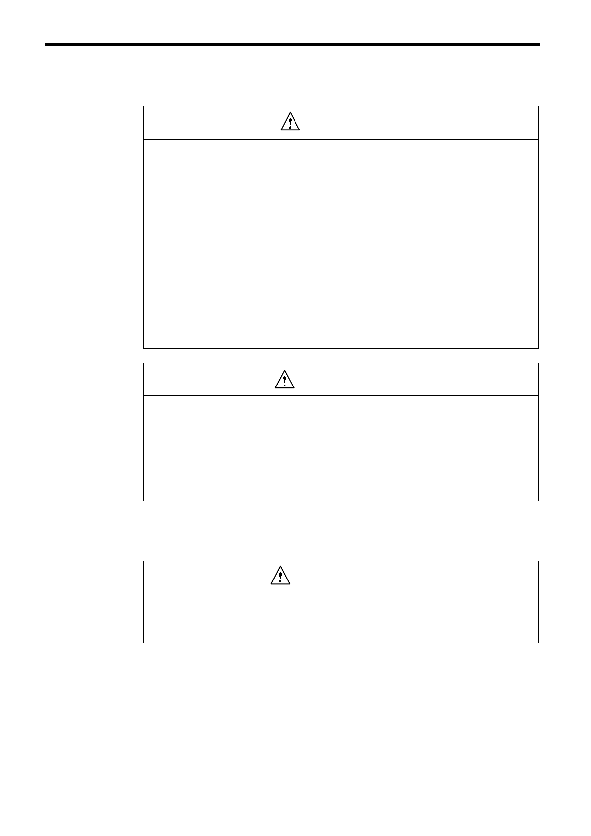
NOTES FOR SAFE OPERATION
Read this instruction manual thoroughly before installation, operation, maintenance or inspection of
the VS-686SS5. In this manual, NOTES FOR SAFE OPERATION are classified as “WARNING”
or “CAUTION.”
WARNING
Indicates a potentially hazardous situation which, if not avoided, could result in death or serious injury
to personnel.
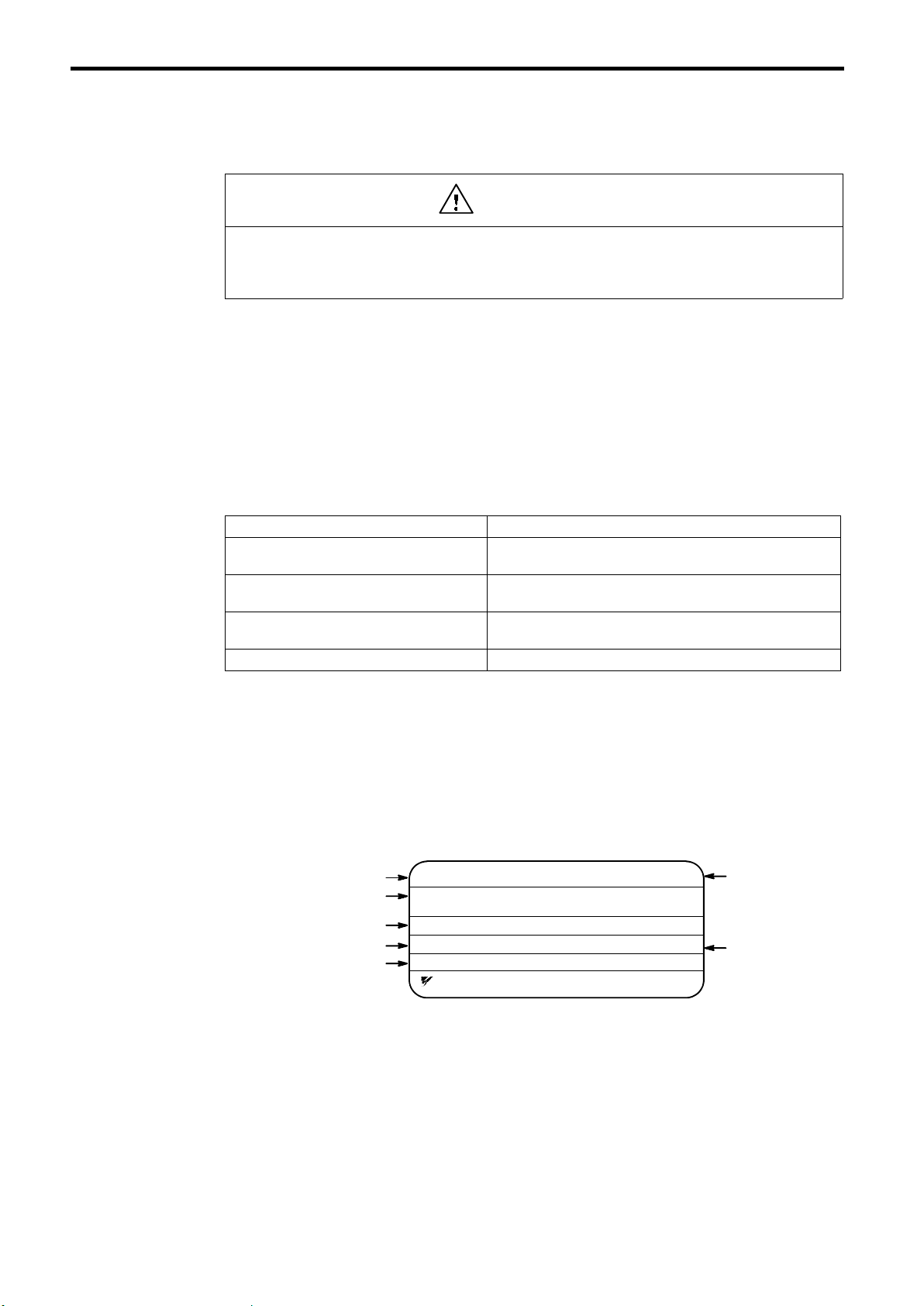
CAUTION
Indicates a potentially hazardous situation which, if not avoided, may result in minor or moderate injury to personnel and damage to equipment.
It may also be used to alert against unsafe practices.
Even items described in
case, follow these important notes.
NOTE
: These are steps to be taken to insure proper operation.
CAUTION
may result in a vital accident in some situations. In either
4
Page 4
NOTES FOR SAFE OPERATION
NOTES ON USE
WARNING
The SS5 motor is a synchronous motor equipped with a built-in, high performance magnet as a rotor.
The SS5 motor terminals continue to produce high voltage whenever the motor is rotating even if
inverter power is OFF. Observe the following when hadling the inverter.
S
Make sure the motor is stopped when carrying out maintenance, inspection or wiring.
S
Connect a low-voltage manual starter to the inverter output side when the motor is rotated
by the load even if the inverter power is OFF.
CAUTION
S
If using a motor with a PG, be sure to confirm the safety and adjust the PG zero-pulse be-
fore starting any operation.
Failure to observe this caution may cause the torque to be insufficient, which may result in the
following motor malfunctions:
• The motor is pulled in the direction of the load.
• The motor rotates in reverse.
• The motor does not rotate.
• The motor suddenly accelerates.
S
Before starting operation, be sure to set the motor constants according to the motor name-
plate values.
Failure to observe this caution may cause torque insufficiency, which result in motor malfunctions:
• The motor is pulled in the direction of the load.
• The motor rotates in reverse direction.
• The motor does not rotate.
• The motor is suddenly accelerated.
RECEIVING
CAUTION
(Ref. page)
S
Do not install or operate any inverter which is damaged or has missing
parts.
Failure to observe this caution may result in personal injury or equipment damage. 14
5
Page 5
INSTALLATION
CAUTION
S Lift the cabinet by the base. When moving the unit, never lift by the front
cover.
Otherwise, the main unit may be dropped causing damage to the unit. 16..........
S Mount the inverter on nonflammable material (i.e. metal).
Failure to observe this caution can result in a fire. 16............................
S When mounting units in an enclosure, install a fan or other cooling device
to keep the intake air temperature below 45_C.
Overheating may cause a fire or damage to the unit. 16........................
WIRING
WARNING
(Ref. page)
S Only commence wiringafter verifying that thepower supply is turnedOFF.
Failure to observe this warning can result in an electric shock or a fire. 20.........
S Wiring should be performed only by qualified personnel.
Failure to observe this warning can result in an electric shock or a fire. 20.........
S When wiring the emergency stop circuit, check the wiring thoroughly
before operation.
Failure to observe this warning can result in personal injury. 20.................
S Make sure to ground the ground terminal .
(Ground resistance
200V class: 100Ω or less, 400V class: 10Ω or less)
Failure to observe this warning can result in an electric shock or a fire. 24.........
(Ref. page)
6
Page 6

NOTES FOR SAFE OPERATION
CAUTION
S Do not connect the other type of motor (i.e. induction motor). The
VS-686SS5 inverter is exclusive-use for SS5 motor drive.
Failure to observe this caution can result in inverter damage. 20.................
S Verify that the inverter rated voltage coincides with the AC power supply
voltage.
Failure to observe this caution can result in personal injury or a fire. 20...........
S Do not perform a withstand voltage test of the inverter.
It may cause semi-conductor elements to be damaged. 20......................
S To connect a braking resistor, braking resistor unit or braking unit, follow
the procedures described in APPENDIX 3.
Improper connection may cause a fire. 20..................................
S Tighten terminal screws to the specified tightening torque.
Failure to observe this caution can result in a fire. 20..........................
(Ref. page)
S Never connect the AC main circuit power supply to output terminals U, V
and W.
The inverter will be damaged and invalidate the guarantee. 24.................
S (Standard connection)
Be sure to connect the motor leads to the correct output terminals:
Motor lead U to output terminal U,
Motor lead V to output terminal V, and
Motor lead W to output terminal W.
Failure to observe this caution may cause the motor to run unusual way such as in
reverse. 24...........................................................
S With the standard connection for the output terminals, the motor rotates
counterclockwise as viewed from the load side in a forward operation.
To rotate the motor clockwise in a forward operation, connect the output
terminals as refered in Appendix 6. 24...................................
7
Page 7
OPERATION
WARNING
S Only turn ON the input power supply after replacingthe front cover. Do not
remove the cover while current is flowing.
Failure to observe this warning can result in an electric shock. 38................
S When the retry function (L5-02) is selected, do not approach the inverter
or the load, since it may restart suddenly after being stopped.
(Construct machine system, so as to assure safety for personnel, even if the
inverter should restart.)
Failure to observe this warning can result in personal injury. 38.................
S Since the stop button can be disabled by a function setting, install a sepa-
rate emergency stop switch.
Failure to observe this warning can result in personal injury. 38.................
S If an alarm is reset with the operation signal ON, the inverter restarts auto-
matically. Only reset the alarm after verifying that the operation signal is
OFF.
Failure to observe this warning can result in personal injury. 38.................
(Ref. page)
S When adjusting PG zero-pulse, disconnect the motor from the machine.
The motor rotates automatically during adjustment. 49....................
S When PG zero-pulse adjustment is completed, “End” is displayed on the
digital operator. Do not touch it until it has come to a complete stop.
The motor starts and stops repeatedly when adjustments are made. 49.......
CAUTION
S Never touch the heatsink or discharging resistor since the temperature is
very high.
Failure to observe this caution can result in harmful burns to the body. 3 8.........
S Since it is easy to change operation speed from low to high speed, verify
the safe working range of the motor and machine before operation.
Failure to observe this caution can result in personal injury and machine damage. 38..
S Install a holding brake separately if necessary.
Always construct the external sequence to confirm that the holding
brake is activated in the event of an emergency, a power failure, or an
abnormality in the inverter occuring.
Failure to observe this caution can result in personal injury. 38..................
(Ref. page)
S If using with an elevator, take safety measures on the machine’s side to
prevent the elevator from dropping.
Failure to observe this caution may result in personal injury. 38.................
S Do not change signals during operation.
The machine or the inverter may be damaged. 38.............................
8
Page 8

NOTES FOR SAFE OPERATION
CAUTION
S All the constants of the inverter have been preset at the factory. Do not
change the settings unnecessarily.
The inverter may be damaged. For supply voltage, follow Par. 4.2. 38............
S Be sure to set the motor constants in accordance with the values listed on
the motor nameplate values. 38........................................
Failure to observe this caution may cause the torque to be insufficient, which
may result in the following motor malfunctions:
• The motor is pulled in the direction of the load.
• The motor rotates in reverse.
• The motor does not rotate.
• The motor suddenly accelerates.
S
Besure to set themotorconstants before the initialoperation and after
replacement of the motor. Reconfirm the motor constants after they
have been set.
Failure to observe this caution may result in motor malfunctions such as
sudden acceleration. 44..............................................
(Ref. page)
S In the following cases when under flux vector control, be sure to adjust
the PG zero-pulse as described in 4.3 (3) (e) PG Zero-pulse Adjustment: 44..
• Before initial operation.
• After replacing the motor.
• After replacing the PG.
S Verify that digital operator STOP LED is ON before checking motor speed
detection. 48........................................................
S Verify that nothing is caught on the shaft or coupling. 48...................
S If the constant b1-06 is set to 1 and the run command is ON, the motor will
start immediately if the following operations are done. Confirm the safety if such operation is required.
•
The operation mode is switched from LOCAL to REMOTE.
•
The power supply is turned ON.
Failure to observe this caution may result in personal injury. 71.................
S Confirm safety. 49....................................................
• Is the motor disconnected from the machine?
• Is the lock key disconnected from the machine?
• Are there any persons or objects near the motor shaft?
• Has the motor come to a complete stop?
9
Page 9
MAINTENANCE AND INSPECTION
WARNING
S Never touch high-voltage terminals in the inverter.
Failure to observe this warning can result in an electric shock. 65................
S Replace all protective covers before powering up the inverter. To remove
the cover, make sure to shut OFF the molded-case circuit breaker.
Failure to observe this warning can result in an electric shock. 65................
S Perform maintenance or inspection only after verifying that the CHARGE
LED goes OFF, after the main circuit power supply is turned OFF.
The capacitors are still charged and can be dangerous. 65......................
S Only authorized personnel should be permitted to perform maintenance,
inspections or parts replacement.
[Remove all metal objects (watches, bracelets, etc.) before operation.]
(Use tools which are insulated against electrical shock.)
Failure to observe this warning can result in an electric shock. 65................
(Ref. page)
CAUTION
(Ref. page)
S The control PC board employs CMOS ICs. Do not touch the CMOS ele-
ments.
They are easily damaged by static electricity. 65.............................
S Do not connect or disconnect wires or connectors while power is applied
to the circuit.
Failure to observe this caution can result in personal injury. 65..................
OTHERS
WARNING
S Never modify the product.
Failure to observe this warning can result in an electrical shock or personal injury and will invalidate the guarantee.
10
Page 10
NOTES FOR SAFE OPERATION
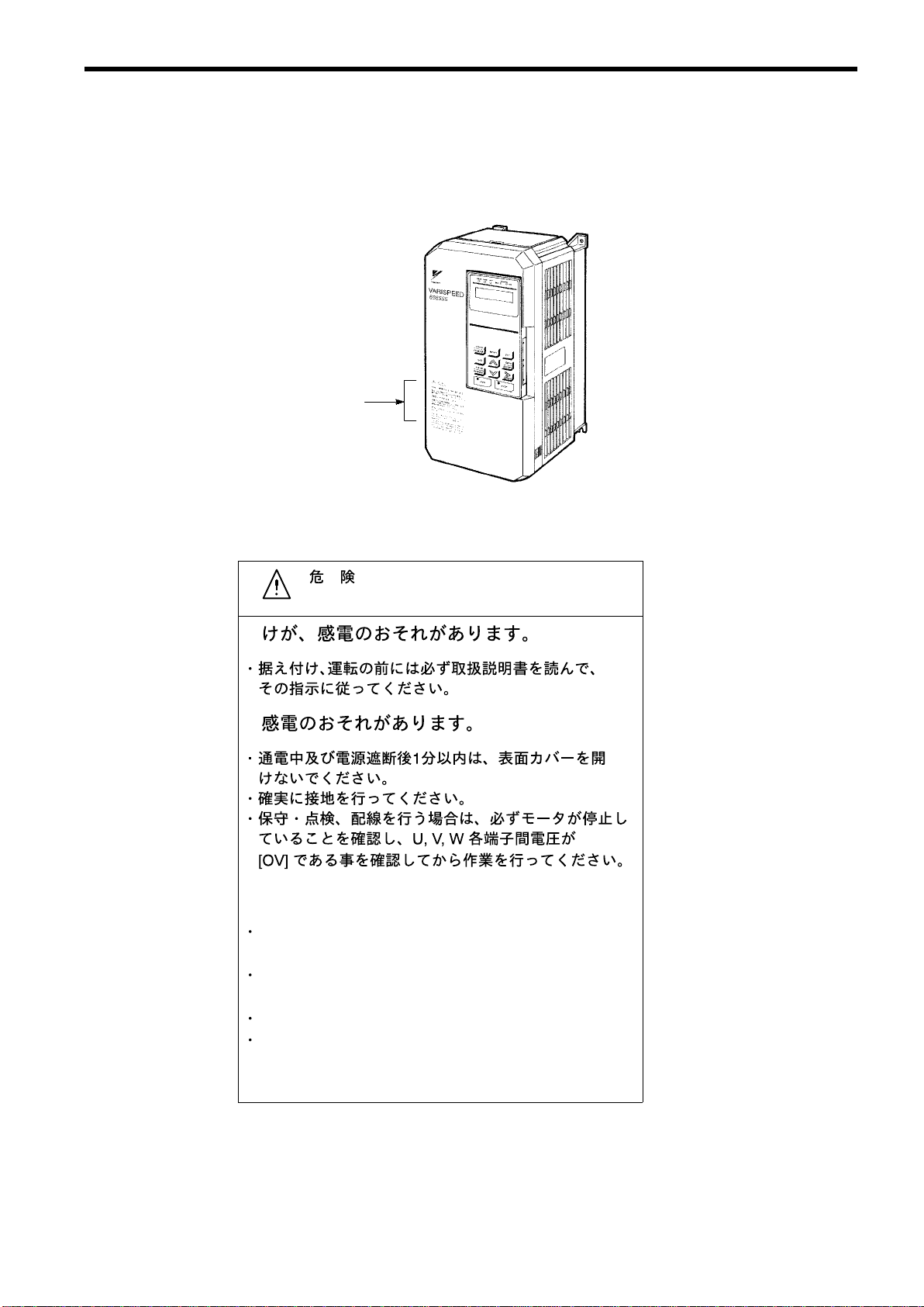
WARNING LABEL
A warning label is displayed on the front cover of the inverter, as shown below. Follow these instructions when handling the inverter.
Warning Label
Model CIMR-SSA23P7
WarningLabel
WARNING
May cause injury or electric shock.
Please follow the instructions in the manual before
installation or operation.
Disconnect all power before opening front cover of unit.
Wait 1 minute until DC Bus capacitors discharge.
Use proper grounding techniques.
Make sure that the motor has stopped and voltage
between terminals U-V, U-W, and V-W is “0 volt” before
maintenance, inspection, or wiring.
11
Page 11

CONTENTS
NOTES FOR SAFE OPERATION 4......................................
1 RECEIVING 14.....................................................
1.1 INSPECTION CHECKPOINTS 14............................................
1.2 IDENTIFYING THE PARTS 15...............................................
2 INSTALLATION 16...................................................
2.1 REMOVING AND REPLACING THE DIGITAL OPERATOR 16...................
2.2 REMOVING AND REPLACING THE FRONT COVER 17........................
2.3 CHOOSING A LOCATION TO MOUNT THE INVERTER 18......................
2.4 CLEARANCES 19.........................................................
3 WIRING 20.........................................................
3.1 CONNECTION WITH PERIPHERAL UNITS 21................................
3.2 CONNECTION DIAGRAM 22................................................
3.3 WIRING THE MAIN CIRCUIT 24.............................................
3.4 WIRING THE CONTROL CIRCUIT 36........................................
3.5 WIRING INSPECTION 37...................................................
4 OPERATION 38.....................................................
4.1 TEST RUN CHECKPOINTS 39..............................................
4.2 SETTING THE LINE VOLTAGE USING JUMPER
4.3 TEST RUN 40.............................................................
(FOR 400V CLASS 18.5kW AND ABOVE) 39..................................
5 SETTING OPERATION CONDITIONS 56...............................
5.1 DIGITAL OPERATOR KEY DESCRIPTION 56.................................
5.2 DIGITAL OPERATOR MODE SELECTION 57..................................
5.3 DRIVE MODE 58..........................................................
5.4 INITIALIZE MODE 61......................................................
5.5 PROGRAM MODE 63......................................................
5.6 MODIFIED CONSTANTS MODE 64..........................................
6 MAINTENANCE AND INSPECTION 65................................
6.1 PERIODIC INSPECTION 66.................................................
6.2 PARTS REPLACEMENT SCHEDULE (GUIDELINES) 66........................
7 TROUBLESHOOTING 67............................................
7.1 FAULT DIAGNOSIS AND CORRECTIVE ACTIONS 67..........................
7.2 MOTOR FAULTS AND CORRECTIVE ACTIONS 71............................
APPENDIX 1 SPECIFICATIONS 72......................................
APPENDIX 2 DIMENSIONS (mm) 74....................................
200 V/400 V Class Inverters of 15 kW and Lower 74...................................
200 V/400 V Class Inverters of 18.5 kW and Higher 74.................................
Mounting Dimensions for 400 V Class Inverters of 220 to 300 kW 74.....................
APPENDIX 3 TYPICAL CONNECTION DIAGRAM 76......................
3.1 BRAKING RESISTOR UNIT 76..............................................
3.2 BRAKING UNIT AND BRAKING RESISTOR UNIT 77...........................
3.3 THREE BRAKING UNITS IN PARALLEL 80...................................
3.4 WITH CONTACT OUTPUT, OPEN COLLECTOR OUTPUT 83...................
12
APPENDIX 4 CONSTANTS LIST 84....................................
Page 12

APPENDIX 5 ERROR PROCESSING IN PG ZERO-PULSE
ADJUSTMENT 90.........................................
APPENDIX 6 ROTATION DIRECTION OF MOTOR 92.....................
APPENDIX 7 ZDEV CAUSES AND CORRECTIVE ACTIONS LIST 93........
Revision History
13
Page 13
1 RECEIVING
S
Do not install or operate any inverter which is damaged or has missing
parts.
Failure to observe this caution may result in personal injury or equipment damage.
This chapter describes how to verify the inverter after delivery to the user.
1.1 INSPECTION CHECKPOINTS
(1)
Receiving Checkpoints
Table 1 Checkpoints
Checkpoints Description
Does the inverter model number correspond with
the purchase order?
Are any parts damaged?
Ishardwareproperly seatedand securelytightened?
Was an instruction manual received? VS-686SS5 instruction manual (No.: TOE-S686-15)
CAUTION
Check the model number on the nameplate on the side of the
VS-686SS5.
Visuallycheck the exterior and verify that there was no damage during
transport.
Remove inverter front cover.
Check all visible hardware with appropriate tools.
If any of the above checkpoints are not satisfactory, contact your YASKAWA representative.
(2)
Checking the Nameplate Data
(a)
Nameplate Data
Example of Japan domestic standard model CIMR-SSA2018 (200VAC 18.5kW)
Inverter Model
Input Spec.
Output Spec.
Lot No.
Serial No.
MODEL : CIMR− SSA2018 SPEC : 20180A
INPUT :
OUTPUT : AC 3PH 0− 230 V 30kVA 80A
LOT NO : MASS : 28kg
SER NO :
YASKAWA ELECTRIC CORPORATION
AC 3PH 200− 220 V 50Hz
200− 230 V 60Hz
JAPAN
Inverter Spec.
Mass
14
Page 14
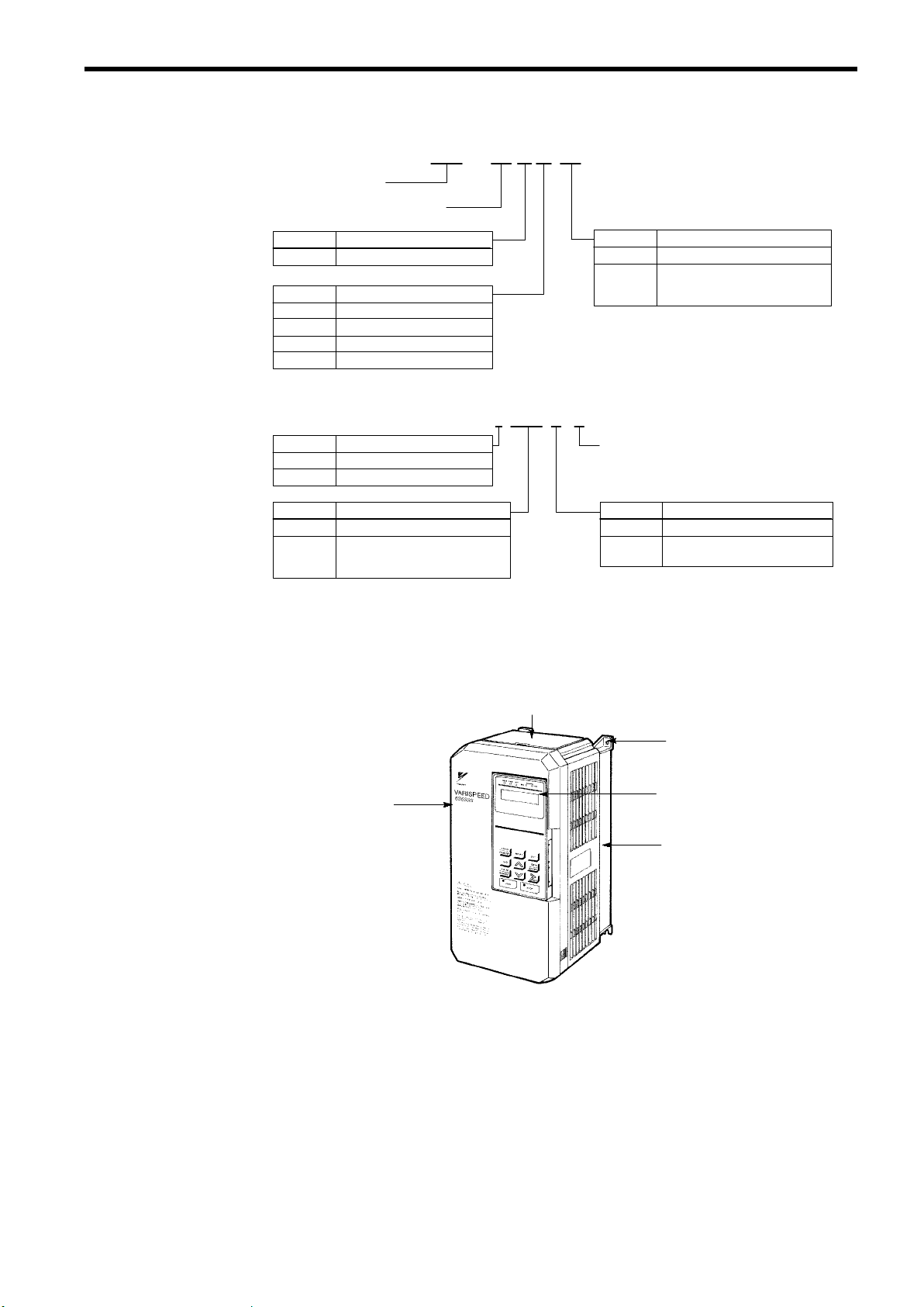
(b)
Model Designation
Inverter
VS-686SS5 Series
1 RECEIVING
CIMR − SS A 2 0P4
Symbol
A
Symbol
2 3-phase 200 V class
4 3-phase 400 V class
D 200 VDC class
E 400 VDC class
(c)
Specification Designation
Symbol
2 3-phase 200 V class
4 3-phase 400 V class
Symbol Max. applicable motor output
0P4 0.4kW
0P7
to
300
* For special specifications, a spec. sheet No. appears on the nameplate.
Specifications
Japan domestic standard
Voltage
Voltage
0.75kW
to
300kW
1.2 IDENTIFYING THE PARTS
2 0P4 1 A *
Symbol Max. applicable motor output
0P4 0.4kW
0P7
to
300
Revision symbol
Symbol
0 Open chassis type
1
Enclosed wall-mounted
type (NEMA 1)
0.75kW
to
300kW
Enclosure
Protective Cover (top/bottom)
4-Mounting Holes
Front Cover
Digital Operator
JVOP-132
Heatsink
Fig.1Configuration of VS-686SS5 (Model CIMR-SSA20P4)
15
Page 15
2 INSTALLATION
CAUTION
S
Lift the cabinet by the base. When moving the unit, never lift by the front cover.
Otherwise, the main unit may be dropped causing damage to the unit.
S
Mount the inverter on nonflammable material (i.e. metal).
Failure to observe this caution can result in a fire.
S
When mounting units in an enclosure, install a fan or other cooling device to keep the intake air temperature below 45_C.
Overheating may cause a fire or damage to the unit.
This chapter describes the configuration, location and space when mounting the VS-686SS5.
2.1 REMOVING AND REPLACING THE DIGITAL OPERATOR
Remove and replace the digital operator as follows.
(1)
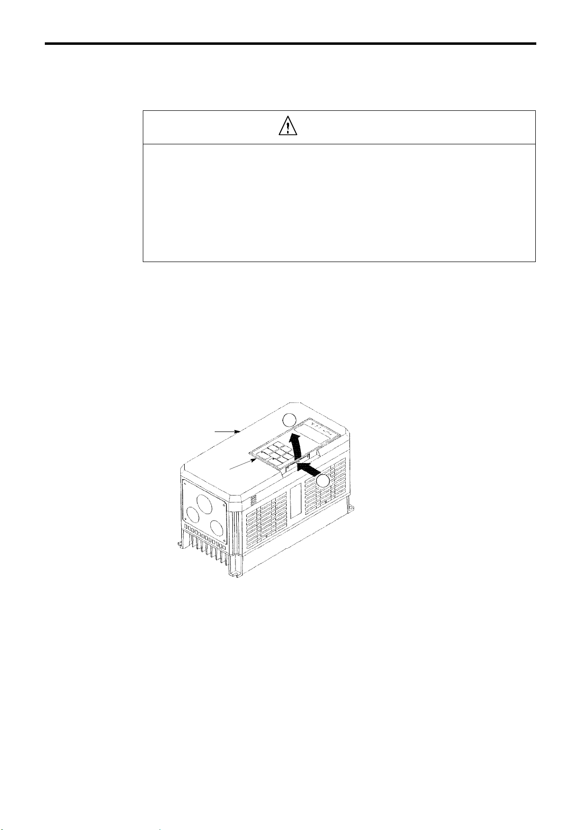
Removing the Digital Operator
Front Cover
Digital Operator
Fig.2Removing the Digital Operator
Push the digital operator lever in the direction
2
1
shown by arrow 1 and lift the digital operator
in the direction shown by arrow 2 to remove
the digital operator from the front cover.
16
Page 16
(2)
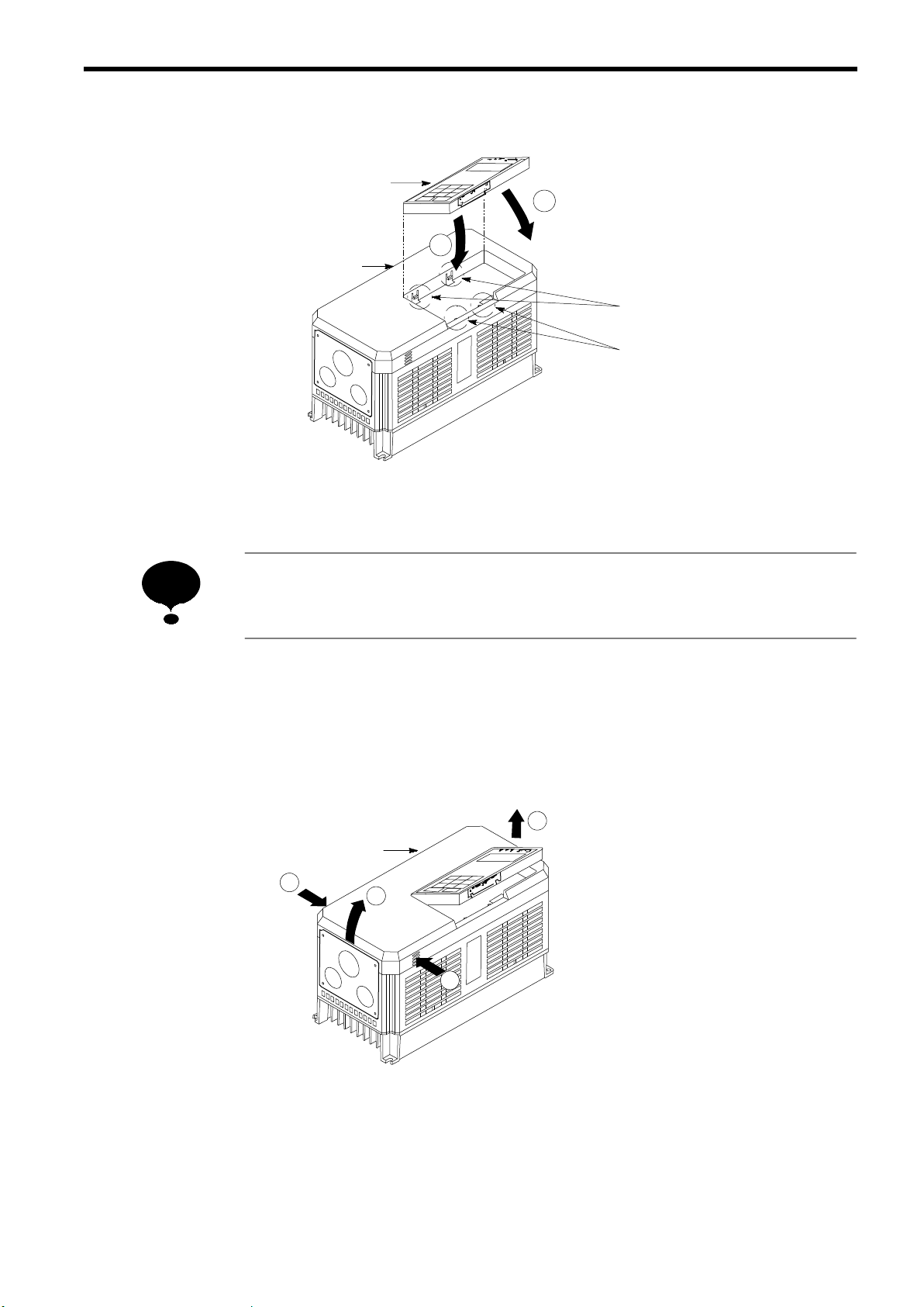
Replacing the Digital Operator
Digital Operator
1
Front Cover
Fig.3Replacing the Digital Operator
2 INSTALLATION
Engage the digital operator on claws A in the
direction shown byarrow 1 and then on claws
2
B in the direction shown by arrow 2 to lock
the digital operator.
Claws A
Claws B
NOTE
Never fit the digital operator in any other direction or by any other method.
The digital operator will not be connected to the inverter.
2.2 REMOVING AND REPLACING THE FRONT COVER
To remove the front cover, first move the digital operator in the direction shown by arrow 1. (See Par.
2.1.) Then squeeze the cover in the direction shown by arrows 2 on both sides and lift in the direction
shown by arrow 3.
1
Front Cover
2
3
2
Fig.4Removing and Replacing the Front Cover
17
Page 17

NOTE
Do not replace the front cover with the digital operator connected. The digital operator will not
be connected to the inverter. Replace the front cover first and then install the digital operator
on the cover. See Par. 2.1 for replacing the digital operator.
2.3 CHOOSING A LOCATION TO MOUNT THE INVERTER
To ensure proper performance and long operating life, follow the recommendations below when
choosing a location for installing the VS-686SS5. Make sure the inverter is protected from the
following conditions:
V Extreme cold and heat.
Use only within ambient temperature range: -10_ C to +40_C
V Rain, moisture. (For enclosed wall-mounted type)
V Oil sprays, splashes
V Salt spray.
V Direct sunlight. (Avoid using outdoors.)
V Corrosive gases or liquids.
V Dust or metallic particles in the air. (For enclosed wall-mounted type)
V Physical shock, vibration.
V Magnetic noise. (Example: welding machines, power devices, etc.)
V High humidity.
V Radioactive materials.
V Combustibles: thinners, solvents, etc.
18
Page 18
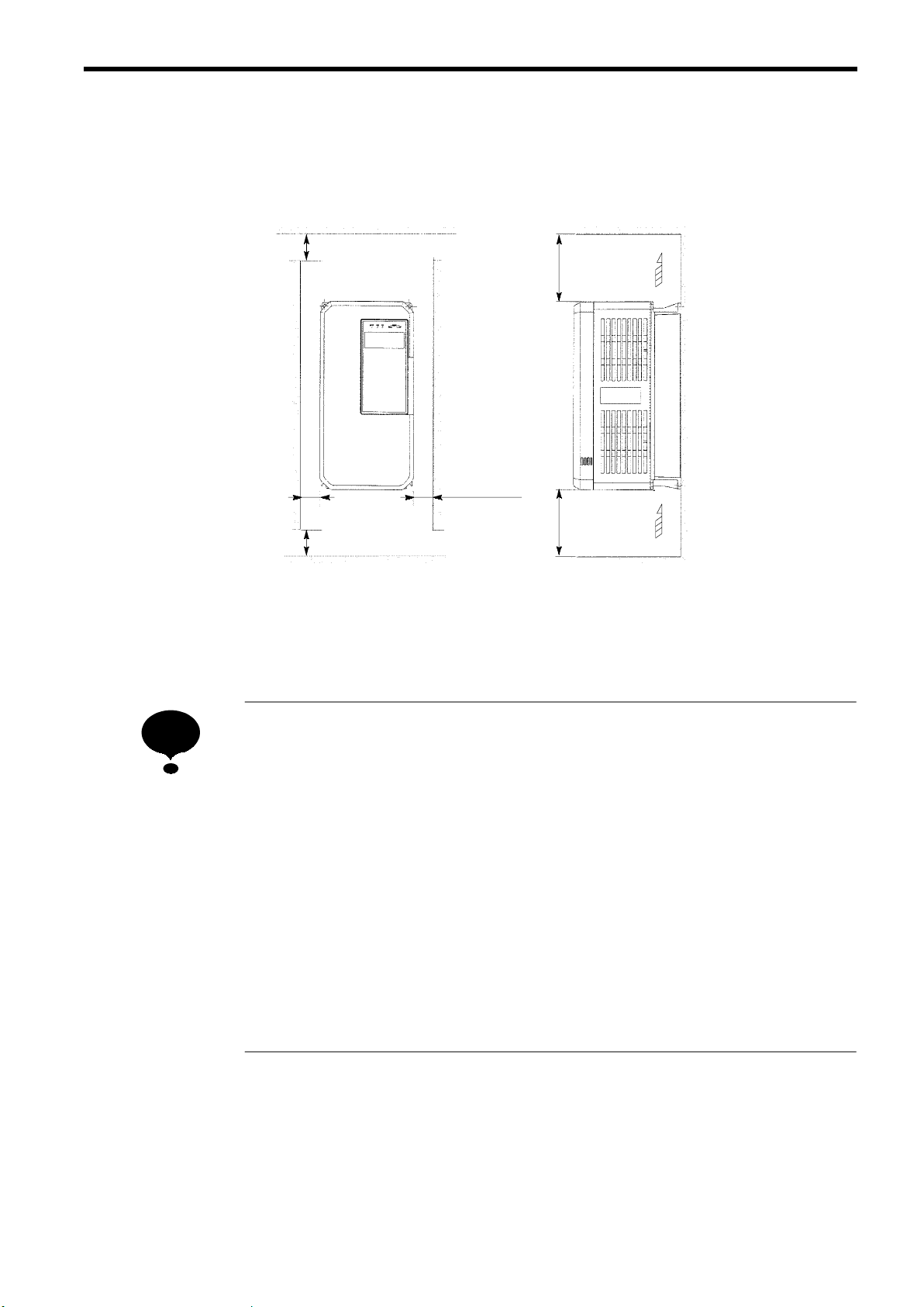
2.4 CLEARANCES
Install the VS-686SS5 vertically and allow sufficient clearances for effective cooling as shown in Fig.
5.
2 INSTALLATION
50 mm or more
*
30 mm or more
*
50 mm or more
(a) Front View
Fig.5Clearances
Air
120 mm or more
30 mm or more
120 mm or more
Air
(b) Side View
NOTE
1. The clearances required at top/bottom and both sides are common in open chassis type
(IP00) and enclosed wall-mounted type (IP20).
2. Remove the top and bottom covers to use the open chassis type of 15kW or less.
3. When installing the models of 30kW or more equipped with eyebolts, extra spacing will
be required on either side. For detailed dimensions, contact your YASKAWA representative.
4. For the external dimensions and mounting dimensions, refer to APPENDIX 2 “DIMEN-
SIONS.”
5. Allowable intake air temperature to the inverter:
Open chassis type : -10_C to +45_C
Enclosed wall-mounted type : -10_C to +40_C
6. Ensure sufficient space for the sections at the upper and lower parts marked with ∗ in order
to permit the flow of intake/exhaust air to/from the inverter.
19
Page 19
3 WIRING
S
S
S
S
S
WARNING
Only commence wiring after verifying that the power supply is turned OFF.
Failure to observe this warning can result in an electric shock or a fire.
Wiring should be performed only by qualified personnel.
Failure to observe this warning can result in an electric shock or a fire.
When wiring the emergency stop circuit, check the wiring thoroughly before operation.
Failure to observe this warning can result in personal injury.
CAUTION
Do not connect the other type of motor (i.e. induction motor). The VS-686SS5 inverter is
exclusive-use for SS5 motor drive.
Failure to observe this caution can result in inverter damage.
Verify that the inverter rated voltage coincides with the AC power supply voltage.
Failure to observe this caution can result in personal injury or a fire.
S
Do not perform a withstand voltage test of the inverter.
It may cause semi-conductor elements to be damaged.
S
To connect a braking resistor, braking resistor unit or braking unit, follow the procedures
described in APPENDIX 3.
Improper connection may cause a fire.
S
Tighten terminal screws to the specified tightening torque.
Failure to observe this caution can result in a fire.
This chapter describes the main circuit wiring and the control circuit wiring of the VS-686SS5.
20
Page 20
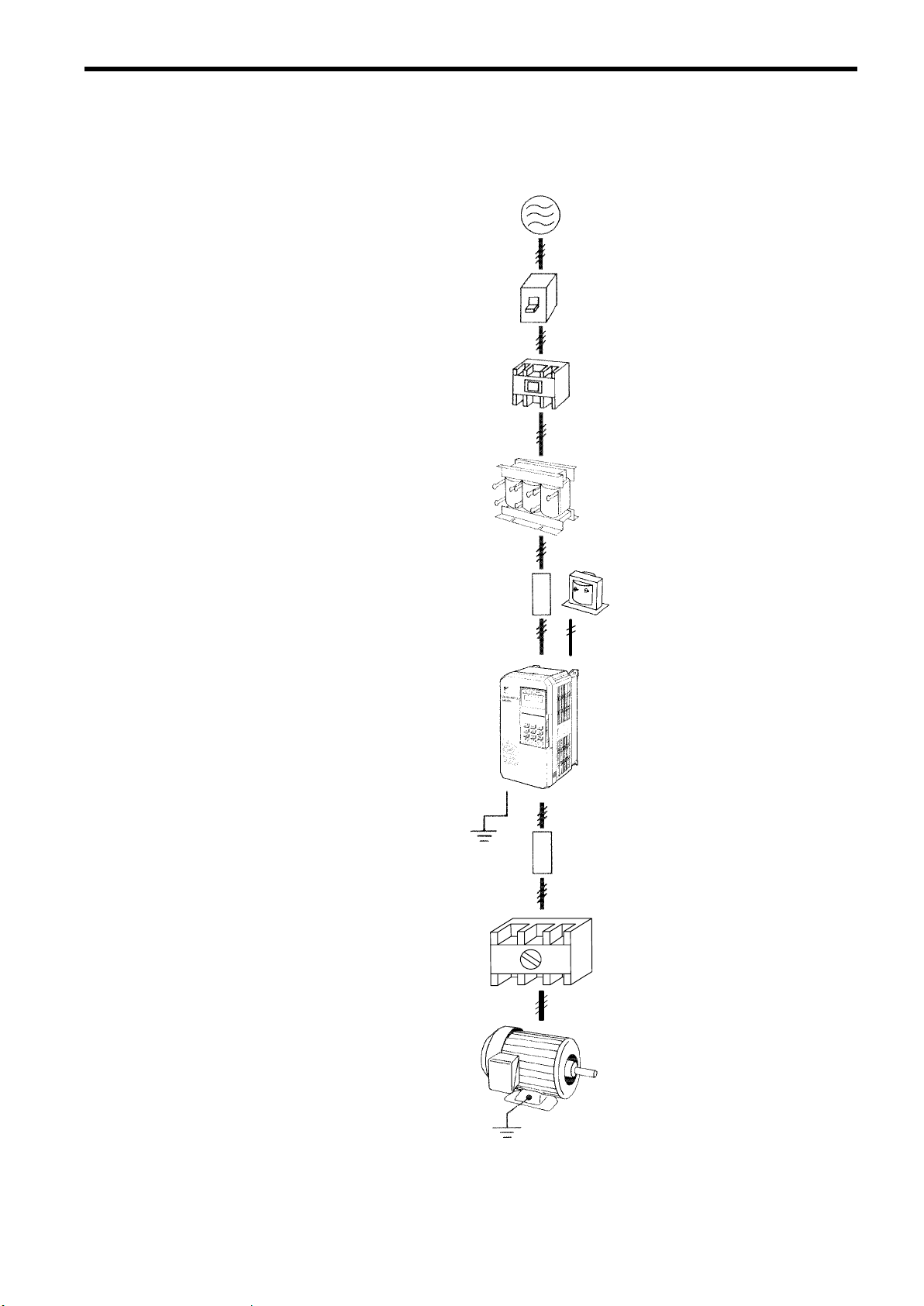
3.1 CONNECTION WITH PERIPHERAL UNITS
The following shows standard connection of the VS-686SS5 with peripheral units.
Power Supply
Molded-case Circuit
Breaker or Ground
Fault Interrupter
Magnetic Contactor
AC Reactor
3 WIRING
Input Noise Filter
VS-686SS5
Output Noise Filter
Low-voltage Manual
Starter
(Used when the motor
is rotated by the load.)
DC Reactor
Grounding
Motor
Grounding
Fig.6Connection with Peripheral Units
21
Page 21
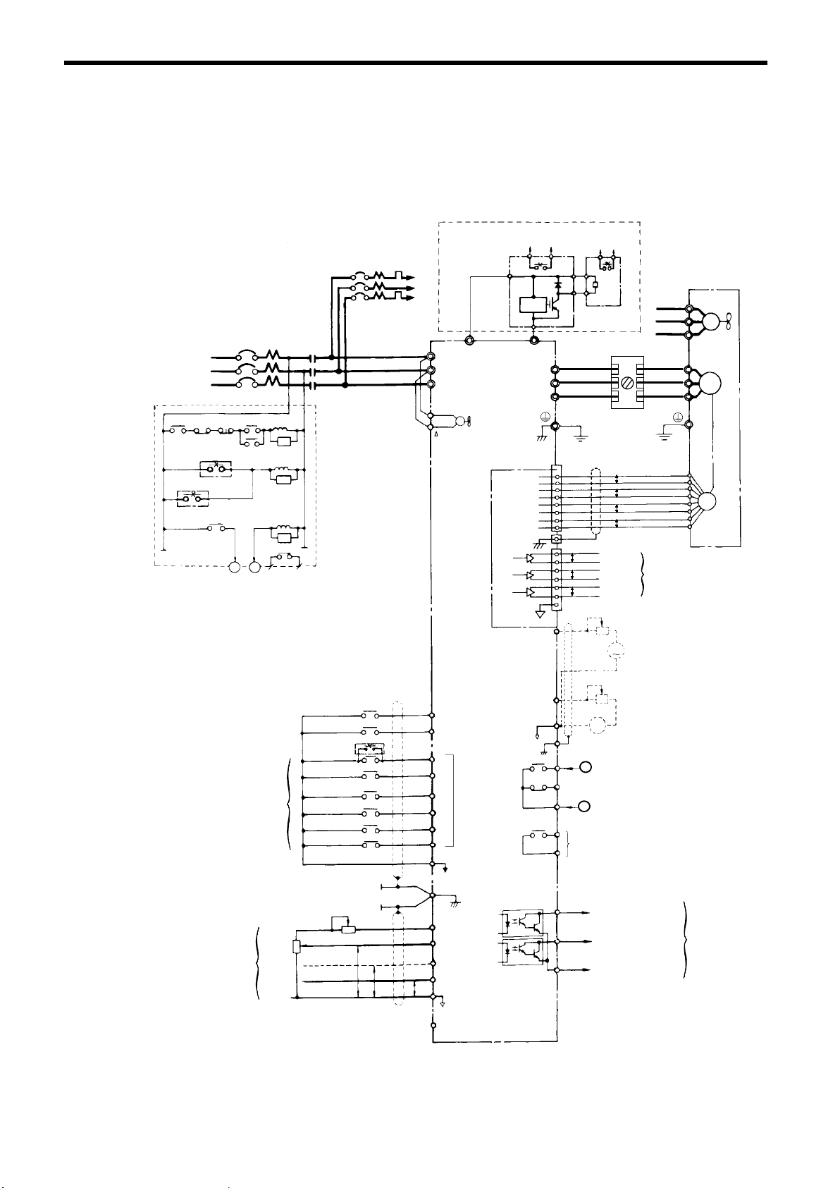
3.2 CONNECTION DIAGRAM
Below is a connection diagram of the main circuit and control circuit. The example shows the models
CIMR-SSA2018 to -SSA2075 (200V class 18.5 to 75kW). Using the digital operator, the motor can
be operated by wiring the main circuit only.
2MCCB
3-Phase
Power Supply
200 to 230V
50/60 Hz
2MCCB
Overload Relay Trip
Contact of Braking Resistor Unit
Overload Relay Trip Contact of
Motor Cooling Fan
1
R
S
T
THRX
12
2
MC
OFF
1MCCB
ON MC
MC
20
18
SA
THRX
SA
TRX
SA
TRX
Fault
Contact
MC
Overload Relay
Trip Contact
Braking Unit
R1
S1
T1
¨ 3
R
S
T
VS-686SS5
Cooling Fan
r
M
¨
PG-X2
3
Level
Detector
©
(E)
4
©
U
V
W
1
2
4
5
6
7
8
9
1
2
3
4
5
6
7
12
¨
P
©
B
Braking Resistor
Unit
Low-voltage Manual Starter
Ground (100 Ω or less)
TA1
P
P
P
TA3
TA2
P
P
P
P
Shielded Wire
Pulse A
Pulse B
Pulse Z
Motor
R1
S1
T1
FV
FW
Fan
IM
Cooling
FU
U
V
M
W
D
F
A
H
B
PG
I
C
J
Pulse Monitor Output
External Speed Reference
Factory
Setting
2kΩ
Forward
Run/Stop
Reverse
Run/Stop
External
Fault
Fault Reset
Multi-step Speed Setting 1
(Master/Aux Change)
Multi-step Speed
Setting 2
Jog Reference
External
Baseblock
34
2kΩ
0 to +10 V
4 to 20mA
0 to +10 V
P
P
0V
1 Forward Run
when CLOSED
2 Reverse Run
when CLOSED
3
4
5
Multi-function
Contact Input
6
7
8
Sequence Common
11
Terminal (0V)
12 Shield Sheath
Connection
Terminal
15 Speed Setting Power
Supply +15 V 20 mA
13 Master Speed Ref.
0 to 10V (20kΩ)
14 Master Speed Ref.
4 to 20mA (250Ω)
16 Multi-function Analog
Input 0 to 10V (20kΩ)
P
17
(Aux. Speed Ref. at Factory
Setting)
0V
33 Speed Setting Power
Supply -15V 20mA
23
21
22
−
(12)
18
18
19
20
20
9
Multi-function Contact Output
250 VAC 1 A or less
10
30 VDC 1 A or less
(Signal during Running at Factory Setting)
25
26
27
Multi-function Analog Monitor 2
+
-10 to +10 V 2mA
A
(Output Current at Factory Setting
−
0 to +10 V)
Frequency Meter Calibration Resistor
RV30YN20S 20kΩ
Multi-function Analog Monitor 1
-10 to +10 V 2mA
+
(Rotation Speed at Factory Setting
N
0 to +10 V)
Fault Contact Output
Contact Capacity:
250 VAC 1A or less
30 VDC 1A or less
Open Collector 1
(Zero Speed Signal at
Factory Setting)
Open Collector 2
(Speed Agree Signal
at Factory Setting)
Multi-function
Output Common
Multi-function
Open Collector
Output
48 V 50 mA or
less
22
7 Connection Diagram
Fig.
Page 22

3 WIRING
NOTE
NOTE
Layout of control circuit terminals
123 4567 8
1.
13 14 15 16 17
indicates shielded wires and indicates twisted-pair shielded wires.
25 26 27 33 18 19 2011 12(G)
21 22 23 9 10
2. Either control circuit terminal 13 or 14 can be used. (For simultaneous inputs, the two
signals are added internally.)
3. Control circuit terminal 15/33 of +15 V/-15 V has a maximum output current capacity of
20 mA.
4. Multi-function analog output should be used for monitoring meters (e.g. output frequency
meter) and should not be used for feedback control system. Use analog monitor cards
(Model AO-12) for the control system, for a more accurate signal.
5. When using a braking resistor unit, set the constant L3-01 to “0” (overvoltage prevention
level is “disabled”). If it is not changed, the motor may not stop within the set decel time.
6. When using model ERF braking resistor (inverter-mounted type), set the constant L8-01
to “01” (braking resistor protection selection to “enabled”). If it is not changed, the braking resistor cannot be protected.
7. When installing a DC reactor (optional for models of 15kW or below), remove the short-
circuit bar between ¨1 and ¨2 terminals and connect a DC reactor with the terminals.
8. The models of 200V 30 to 75kW or 400V 55 to 160kW cannot be connected with DC pow-
er supply.
9. Once external baseblock signal is turned ON, do not release until a motor stops.
23
Page 23

3.3 WIRING THE MAIN CIRCUIT
S Make sure to ground the ground terminal .
(Ground resistance 200V class: 100Ω or less, 400V class: 10Ω or less)
Failure to observe this warning can result in an electric shock or a fire.
S Never connect the AC main circuit power supply to output terminals U, V and W.
The inverter will be damaged and invalidate the guarantee.
S (Standard connection)
Be sure to connect the motor leads to the correct output terminals:
Motor lead U to output terminal U,
Motor lead V to output terminal V, and
Motor lead W to output terminal W.
Failure to observe this caution may cause the motor to run unusual way such as in reverse.
S With the standard connection for the output terminals, the motor rotates counterclock-
wise as viewed from the load side in a forward operation. To rotate the motor clockwise
in a forward operation, connect the output terminals as refered in Appendix 6.
WARNING
CAUTION
(1) Wiring Precautions for Main Circuit Input
(a) Installation of Molded-case Circuit Breaker (MCCB)
Make sure to connect MCCBs or fuses between the AC main circuit power supply and
VS-686SS5 input terminals R, S and T to protect wiring.
(b) Installation of Ground Fault Interrupter
When connecting a ground fault interrupter to input terminals R, S and T, select one that
is not affected by high frequency.
Examples: NV series by Mitsubishi Electric Co., Ltd. (manufactured in or after1988),
EG, SG series by Fuji Electric Co., Ltd. (manufactured in or after 1984)
24
Page 24

3 WIRING
(c) Installation of Magnetic Contactor
Inverter can be used without a magnetic contactor (MC) installed at the power supply side.
When the main circuit power supply is shut OFF in the sequence, a magnetic contactor (MC)
can be used instead of a molded-case circuit breaker (MCCB). However, when a magnetic
contactor is switched OFF at the primary side, regenerative braking does not function and
the motor coasts to a stop.
S The load cannot be operated/stopped by opening/closing the magnetic contactor at the
power supply side.
S When using a brakingresistor unit, use a sequencer to break power supply side on over-
load relay trip contact. If the inverter malfunctions, the braking resistor unit may be
burned out.
(d) Terminal Block Connection Sequence
Input power supply phases can be connected to any terminal regardless of the order of R,
S and T on the terminal block.
(e) Installation of Reactor
When connecting an inverter (200V/400V 15kW or less) to a large capacity power supply
transformer (600kVA or more), or when switching a phase advancing capacitor, excessive peak current flows in the input power supply circuit, which may damage the converter
section. In such cases, install a DC reactor (optional) between inverter ¨1 and ¨2 terminals or an AC reactor (optional) on the input side. Installation of a reactor is effective for
improvement of power factor on the power supply side.
(f) Installation of Surge Suppressor
For inductive loads (magnetic contactors, magnetic relays, magnetic valves, solenoids,
magnetic brakes, etc.) connected near the inverter, use a surge suppressor simultaneously.
(g) Prohibition of Installation of Phase Advancing Capacitor
If a phase advancing capacitor or surge suppressor is connected in order to improve the
power factor, it may become overheated and damaged by inverter high harmonic components. Also, the inverter may malfunction because of overcurrent.
(h) Using Input Noise Filters
Noise filters can reduce a higher harmonics noise leaking from the drive unit to the power
line.
S Example 1
Power
Supply
MCCB
MCCB
Noise
Filter
VS-686SS5
Other
Control
Device
Fig. 8 Using Input Noise Filter (Example 1)
Use an exclusive noise filter
specified for the inverter.
M
25
Page 25
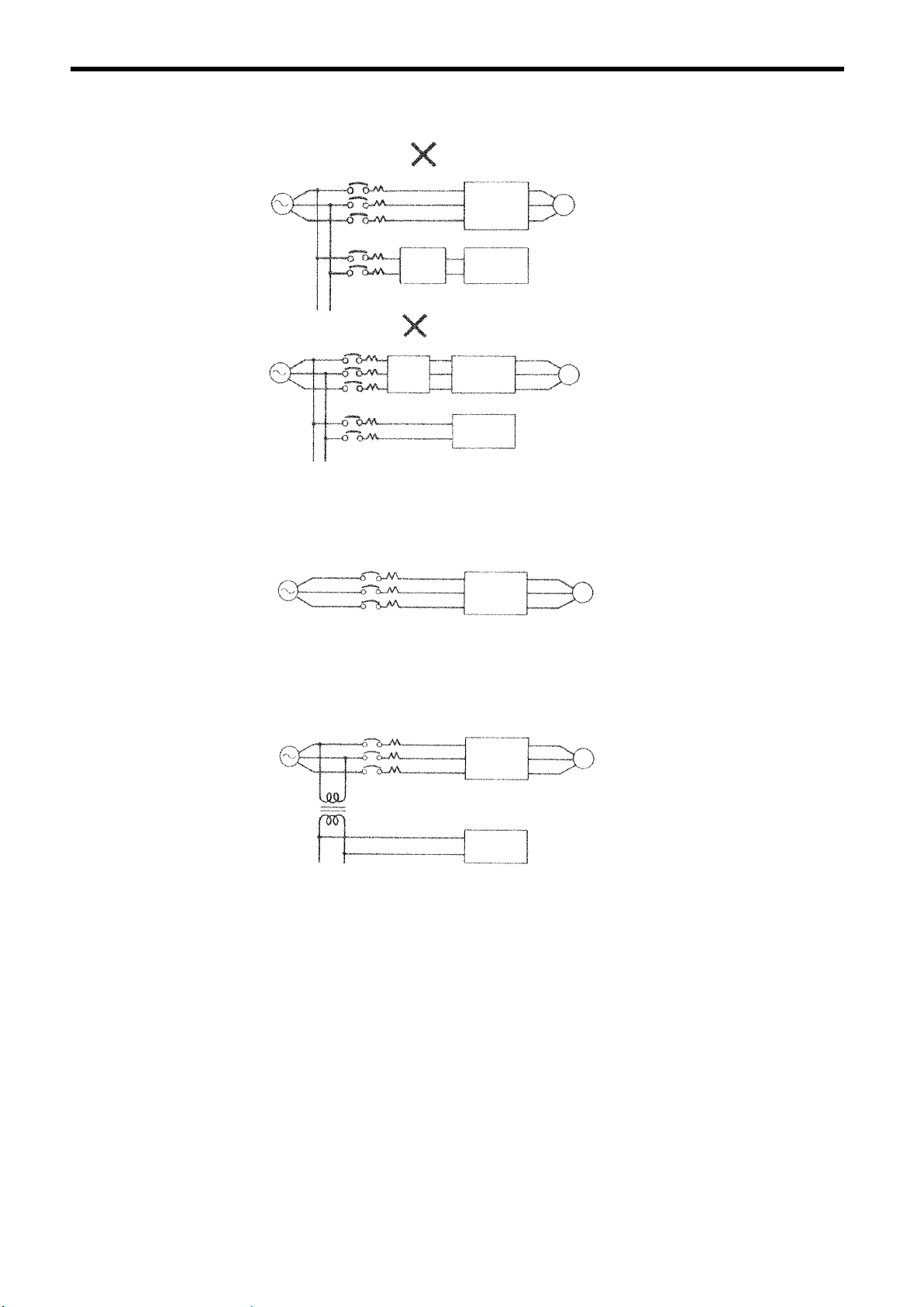
S Example 2
Power
Supply
Power
Supply
MCCB
MCCB
MCCB
MCCB
General
Noise
Filter
General
Noise
Filter
VS-686SS5
Other
Control
Device
VS-686SS5
Other
Control
Device
Fig. 9 Using Input Noise Filter (Example 2)
S Example 3
Power
Supply
MCCB
VS-686SS5
A general-purpose noise
filter will not effective.
M
M
When one inverter is installed
on one power line, a noise fil-
M
ter is not required.
Fig. 10 Using Input Noise Filter (Example 3)
S Example 4
Power
Supply
MCCB
Isolating Transformer
VS-686SS5
Other
Control
Device
Fig. 11 Using Input Noise Filter (Example 4)
By installing an isolating trans-
former on the power side of
M
another control device, the
same result as with installing a
noise filter is achieved.
26
Page 26

(2) Wiring Precautions for Main Circuit Output
(a) Connection of Terminal Block and Load
Connect output terminals U, V and W to motor lead wires U, V and W. For standard connections, be sure to connect the motor leads to the correct output terminals: motor lead U to
output terminal U, motor lead V to output terminal V, and motor lead W to output terminal
W.
With the standard connection for the output terminals, the motor rotates counterclockwise
as viewed from the load side in a forward operation. To rotate the motor clockwise in a forward operation, connect the output terminals as refered in Appendix 6.
(b) Strict Prohibition of Connection of Input Power Supply to Output Terminals
3 WIRING
Never connect the input
power supply to output terminals U, V and W.
(c) Installation of Low-voltage Manual Starter
Make sure to connect a low-voltage manual starter to the inverter output side when the motor is rotated by the load even if the inverter power supply is OFF. Turn OFF the starter before performing maintenance/inspection or wiring.
Example: LB series of AICUT manufactured by Aisei
(d) Strict Prohibition of Short Circuiting or Grounding of Output Circuit
Never touch the output circuit directly or put the output line in contact with the inverter case.
Otherwise, it may cause an electric shock or grounding. In addition, never short circuit the
output line.
(e) Prohibition of Connection of Phase Advancing Capacitor or LC/RC Line Filter
Never connect a phase advancing capacitor or LC/RC line filter to the output circuit.
(f) Avoidance of Installation of Magnetic Starter
Do not connect a magnetic starter or magnetic contactor to the output circuit. If the load
is connected while the inverter is running, the inverter overcurrent protective circuit operates because of inrush current.
(g) Installation of Thermal Overload Relay
An electronic overload protective function is incorporated into the inverter. When using
a thermal overload relay, set inverter constant L1-01 to 0 (motor protection selection: disabled).
27
Page 27
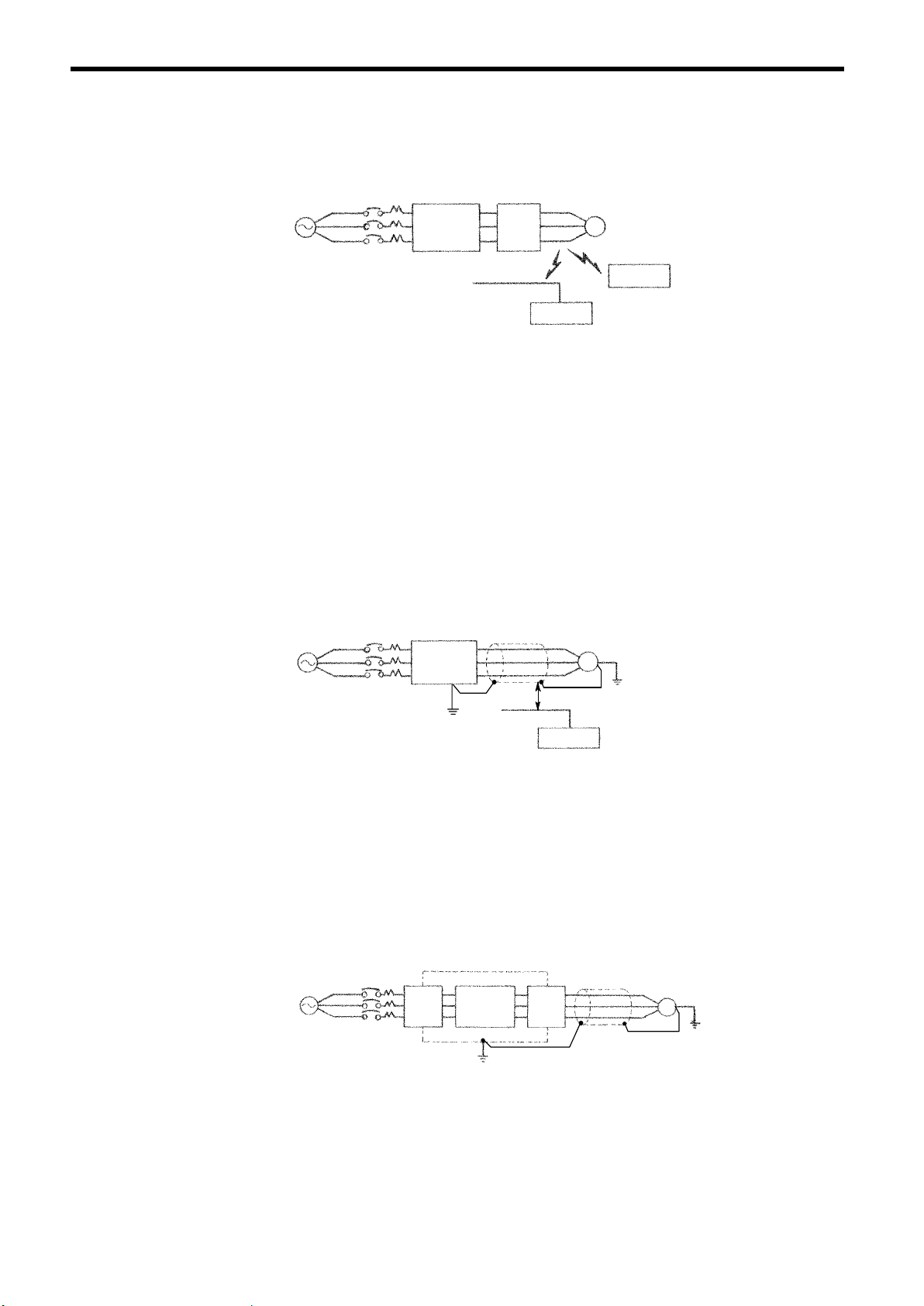
(h) Using Output Noise Filters
By installing a noise filter on the output side of the inverter, radio frequency interference
(RFI) and inductive noise are reduced.
Power
Supply
MCCB
VS-686SS5
Noise
Filter
Inductive
Noise
Signal Line
Control
Device
M
RFI Noise
AM Radio
Fig. 12 Using Output Noise Filter
Inductive noise: Noise coming on the signal line due to electromagnetic inductance can
cause malfunctioning of a control device.
RFI noise: Higher harmonics waves from the inverter or cable can interfere with radio
receiver.
(i) Countermeasures Against Inductive Noise
As described previously,a noise filter can be used to prevent inductive noise fromgenerated
on the output side. Alternatively, cables can be routed through a grounded metal pipe to
prevent inductive noise. Keeping the metal pipe at least 30 cm away from the signal line
considerably reduces inductive noise.
Power
Supply
MCCB
VS-686SS5
Metal Pipe
M
30 cm min.
Signal Line
Control
Device
Fig. 13 Countermeasures Against Inductive Noise
(j) Countermeasures Against RFI Noise
RFI noise is generated form the inverter as well as from the input andoutput lines. To reduce
RFI noise, install noise filters on both input and output sides, and also install in a totally enclosed steel box. The cable between the inverter and the motor should be as short as possible.
Power
Supply
MCCB
Noise
Filter
Steel Box
VS-686SS5
Noise
Filter
Metal Pipe
M
Fig. 14 Countermeasures Against RFI Noise
28
Page 28
3 WIRING
(k) Wiring Distance between Inverter and Motor
If the total wiring distance between inverter and motor is excessively long and the inverter
carrier frequency (main transistor switching frequency) is high, harmonic leakage current
from the cable will adversely affect the inverter and peripheral devices.
Consider the wiring distance between inverter and motor when increasing the carrier frequency value. Carrier frequency can be set by constant C6-02.
Table 2 Wiring Distance between Inverter and Motor
Wiring Distance between
Inverter and Motor
(Set value of constant C6-02)
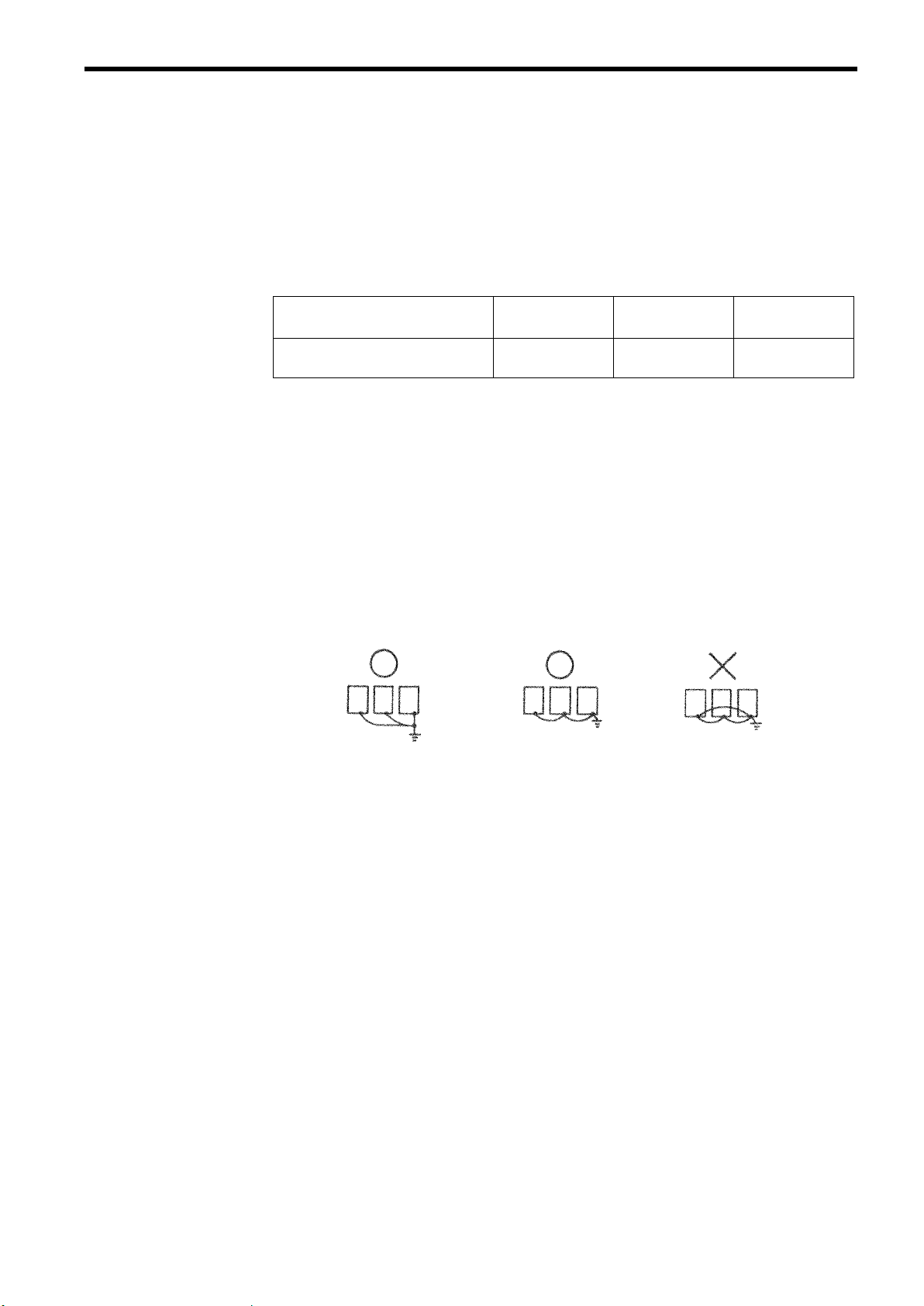
(3) Grounding
S Ground resistance
S Never ground the inverter in common with welding machines, motors, or other large-
S Use the ground wires described in Table5 or 6 and keep the length as short as possible.
S When using several inverter units side by side, ground the units as shown in Fig. 15,
Up to 50m From 50m to 100m More than 100m
Carrier Frequency
12kHz or less
(Max. 12)
8kHz or less
(Max. 8)
200V class : 100Ω or less, 400 V class : 1 0Ω or less.
current electrical equipment.
(a) or (b). Do not loop the ground wires as shown in (c).
(a) Acceptable
(b) Acceptable
(c) Not Acceptable
4kHz or less
(Max. 4)
Fig. 15 Grounding of Three Inverter Units
29
Page 29
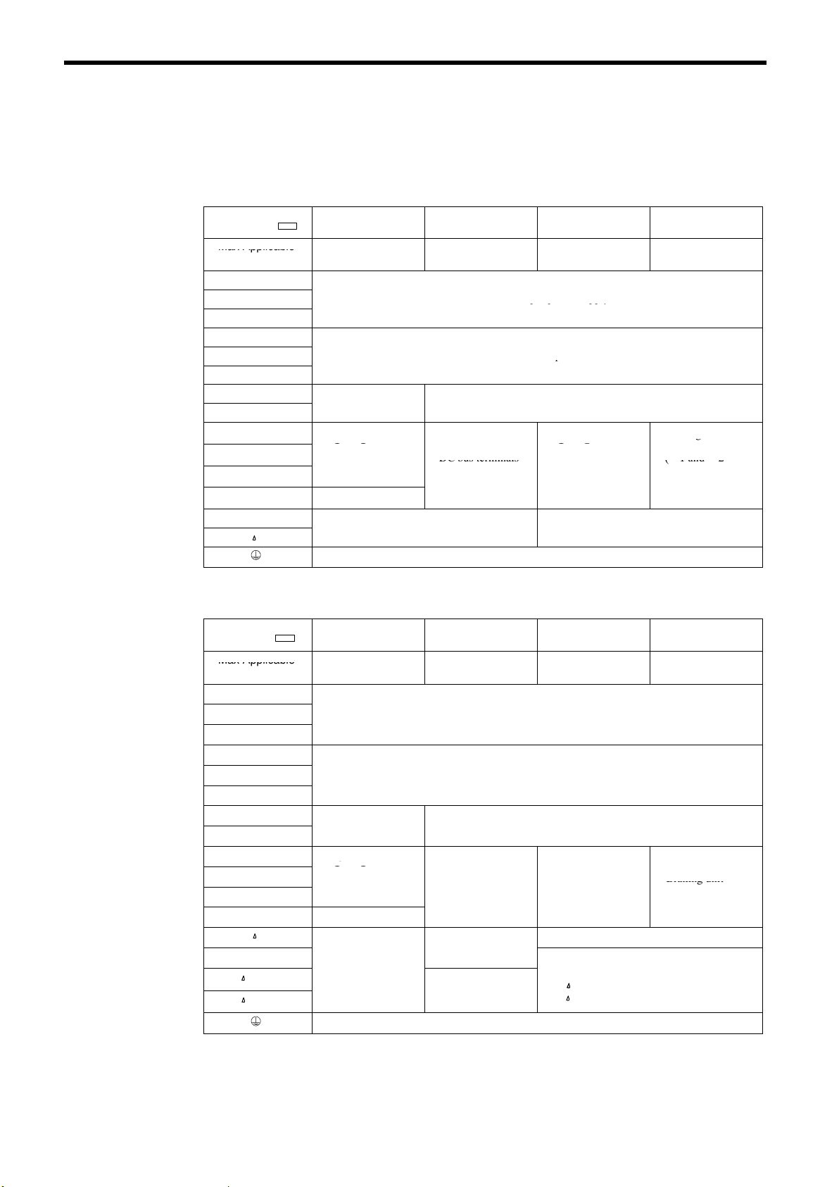
(4) Functions of Main Circuit Terminals
Max
Applicable
0
kW11to15kW
18
22kW30
kW
pppp y
p
C
C
C
u
g
(
)
DC
bus
terminals
DC
bus
terminals
g
Braking
unit
(¨1
and¨2
•
Braking
unit
provided)
Max
Applicable
0
kW
18
kW
160kW18
300
kW
g
C
Braking
unit
(
)
•
DC
bus
terminals
(¨1©)
(¨1and¨2
Braking
unit
(¨3
©
)
(¨2
terminal
not
Cooling
fan
power
Cooling
fan
power
supply
p
r-200:200to230VAC
input
The following table outlines the functions of the main circuit terminals. Wire according to each
terminal function.
Table 3 200V Class Terminal Functions
Models
CIMR-SSA
Max Applicable
Motor Output
R (L1)
S (L2)
T (L3)
U (T1)
V (T2)
W (T3)
B1
B2
©
¨ 1
¨ 2
¨ 3
r
20P4 to 27P5 201 1 to 2015 2018 to 2022 2030 to 2075
.4 to 7.5
Braking resistor unit
• DC reactor
(¨1-¨2)
• DC bus terminals
(¨1-©)
• DC reactor • DC bus terminals
(¨ 1-¨ 2)
• DC bus terminals
(¨ 1-© )
• Brakin
(¨3-©)
Ground terminal (Ground resistance : 100Ω or less)
Table 4 400V Class Terminal Functions
.5 to
Main circuit input power supply
Inverter output
(¨1-©)
• Braking unit
unit
(¨3-©)
Cooling fan power supply
to 75
• Braking unit
¨3-©
(¨1 and ¨2
terminals not
provided) *
Models
CIMR-SSA
Max Applicable
Motor Output
R (L1)
S (L2)
T (L3)
U (T1)
V (T2)
W (T3)
B1
B2
©
¨ 1
¨ 2
¨ 3
r
200
400
40P4 to 4015 4018 to 4045 4055 to 4160 4220 to 4300
.4 to15
Braking resistor unit
• DC reactor
(¨1-¨2)
• DC bus terminals
(¨1-©)
.5 to 45
Main circuit input power supply
Inverter output
• DC bus terminals
(¨1-©)
• Braking unit
-
-
Coolingfanpower
supply
Ground terminal (Ground resistance : 10Ω or less)
55 to
• Brakin
• Cooling fan power supply
unit
(¨3-© )
terminals not
provided)
(Control power supply)
r - 200 : 200 to 230 VAC in
r - 400 : 380 to 460 VAC input
*
5to
• DC bus terminals
¨1-©
• Braking unit
(¨3-© )
provided)
ut
* The models of 200V 30 to 75kW or 400V 55 to 160kW cannot be connected with DC power
supply. Terminal ¨3 is for exclusive use for connecting a braking unit. Do not connect DC
power supply to terminal ¨3.
30
Page 30
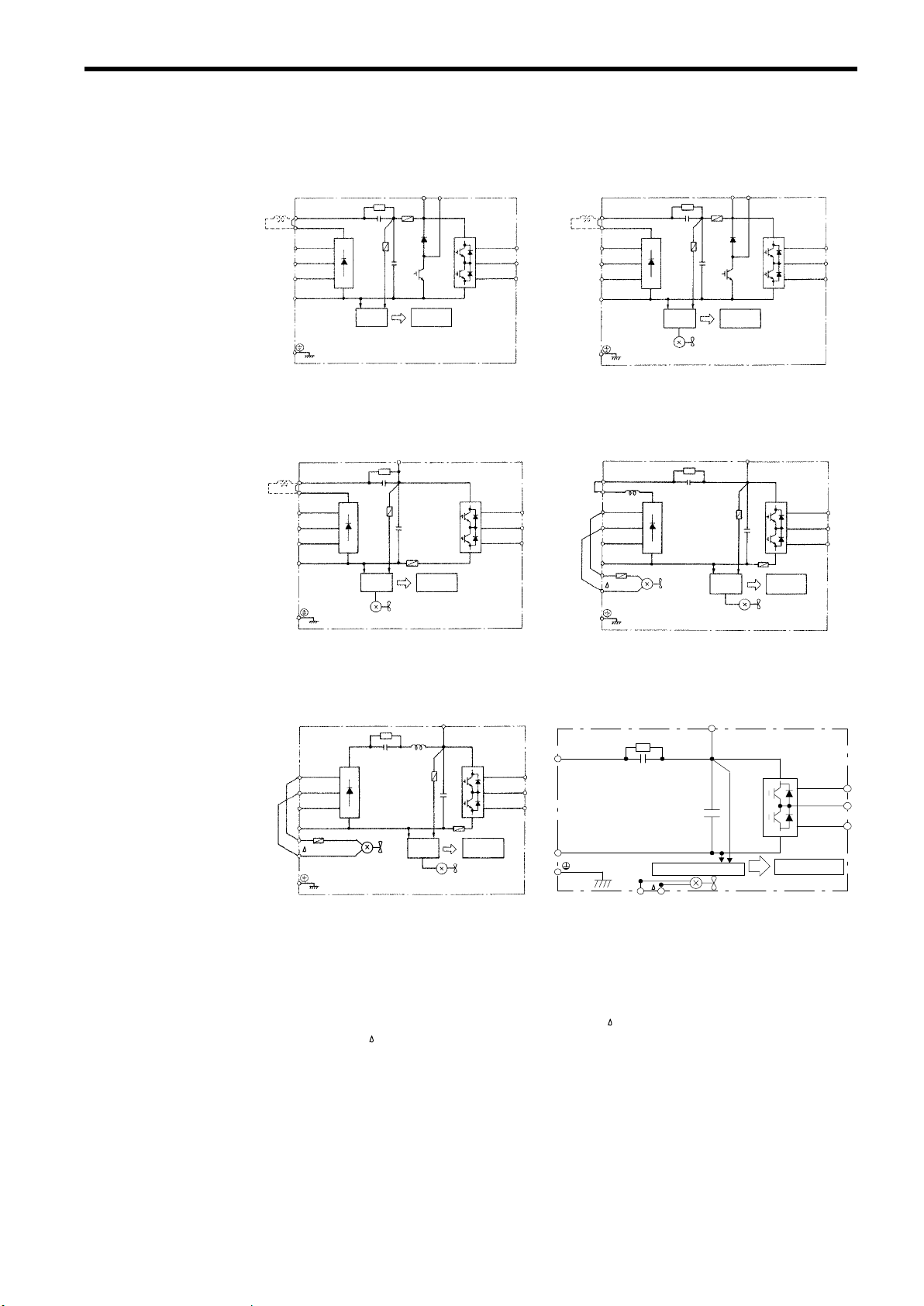
(5) Main Circuit Configuration
200V Class
CIMR-SSA20P4 to 21P5 CIMR-SSA22P2 to 27P5
+
Control
Circuit
B2B1
U(T1)
V(T2)
W(T3)
(DCL
Option)
:1
:2
¨1
¨2
R(L1)
S(L2)
T(L3)
©
(DCL
Option)
:1
:2
¨1
¨2
R(L1)
S(L2)
T(L3)
©
Power
Supply
(RCC)
CIMR-SSA2011 to 2015 CIMR-SSA2018 to 2022
¨3 ¨3
(T1)
U
(T2)
V
(T3)
W
Power
Supply
+
(RCC)
Cooling Fan
Control
Circuit
:3
:1
¨1
¨2
R
S
T
©
r
Cooling Fan
(DCL
Option)
:1
:2
¨1
¨2
R(L1)
S(L2)
T(L3)
©
Power
Supply
+
(RCC)
Cooling Fan
Power
Supply
(RCC)
Control
Circuit
B2B1
+
Control
Circuit
Internal
Cooling Fan
3 WIRING
U(T1)
V(T2)
W(T3)
U
V
W
CIMR-SSA2030 to 2075 CIMR-SSAD030*4to D045
¨3
¨1
:1
R
S
T
©
r
Cooling Fan
Power
Supply
+
(RCC)
Control
Circuit
Internal
Cooling Fan
U
V
W
©
Power Supply (RCC)
r
*1: The wiring has been completed at the factory prior to shipping.
*2: When installing aDCreactor(option) on models of 15kW or below,removetheshort-circuit
bar between ¨1 and ¨2 terminals and connect a DC reactor with the terminals.
*3: The wiring has been completed at the factory prior to shipping. When using main circuit
power supply as DC input, remove the wirings of R - r and S ply to r and
.
and connect AC power sup-
*4: The CIMR-SSD030 motor is under development.
¨3
+
Cooling Fan
U
V
W
Control Circuit
31
Page 31

400V Class
CIMR-SSA40P4 to 41P5 CIMR-SSA42P2 to 4015
+
Control
Circuit
B2B1
U(T1)
V(T2)
W(T3)
(DCL
Option)
:2
:1
¨1
¨2
R(L1)
S(L2)
T(L3)
©
Power
Supply
+
(RCC)
Cooling Fan
(DCL
Option)
:1
:2
¨1
¨2
R(L1)
S(L2)
T(L3)
©
Power
Supply
(RCC)
CIMR-SSA4018 to 4045 CIMR-SSA4055 to 4160
Power
Supply
(RCC)
¨3
+
Control
Circuit
Internal
Cooling Fan
U
V
W
:1
R
S
T
©
r
200
400
Cooling Fan
)
Power
Supply
:1
:3
¨1
¨2
©
r
R
S
T
Cooling Fan
Control
Circuit
(RCC
B2B1
¨3
+
Control
Circuit
Internal
Cooling Fan
U(T1)
V(T2)
W(T3)
U
V
W
CIMR-SSA4220 to 4300 CIMR-SSAE075*4to E110
Power
Supply
(RCC)
¨3
+
Control
Circuit
¨1
U
V
W
©
r
200 400
:3
¨1
R
S
T
©
r
200
400
Cooling Fan
*1: The wiring has been completed at the factory prior to shipping.
*2: When installing a DC reactor (option) on models of 15 kW or below,removetheshort-circuit
bar between ¨1 and ¨2 terminals and connect a DC reactor with the terminals.
*3: The wiring has been completed at the factory prior to shipping. When using main circuit
power supply as DC input, correct the wirings as follows.
• CIMR-SSA4018 to 4045
Remove the wirings of R - r and S -
and connect AC power supply to r and .
• CIMR-SSA4220 to 4300
Remove the wirings of R - r and S -
400 and connect AC power supply to r and 400.
*4: The CIMR-SSAE075 motor is under development.
¨3
+
Power Supply (RCC)
Cooling Fan
Control
Circuit
U
V
W
32
Page 32

(6) Parts Required for Wiring
SSA20P4
M4
2to5.5
SSA20P7
M4
2to5.5
SSA22P2
M4
3.5to5.5
SSA23P7
M4
5.5
q
wireorequivalent
Select wires or closed-loop connectors to be used for wiring from Tables 5, 6 and 7.
Table 5 200V Class Wire Size
3 WIRING
Circuit
Main
Control
Model
CIMR-
SSA21P5
SSA25P5
SSA27P5
SSA2011
SSA2015
SSA2018
SSA2022
SSA2030
SSA2037
SSA2045
SSA2055
SSA2075
Common to all
models
Terminal Symbol
R, S, T, © , ¨ 1,¨ 2, B1, B2, U, V, W
R, S, T, © , ¨ 1,¨ 2, B1, B2, U, V, W
R, S, T, © , ¨ 1,¨ 2, B1, B2, U, V, W
R, S, T, © , ¨ 1,¨ 2, B1, B2, U, V, W
R, S, T, © , ¨ 1,¨ 2, B1, B2, U, V, W
R, S, T, © , ¨ 1,¨ 2, B1, B2, U, V, W
R, S, T, © , ¨ 1,¨ 2, B1, B2, U, V, W
R, S, T, © , ¨ 1,¨ 2, ¨ 3, U, V, W
R, S, T, © , ¨ 1,¨ 2, ¨ 3, U, V, W M8 30
R, S, T, © , ¨ 1,¨ 2, ¨ 3, U, V, W
r, M4 0.5 to 5.5
R, S, T, © , ¨ 1,¨ 2, ¨ 3, U, V, W
r, M4 0.5 to 5.5
R, S, T, U, V, W M10 38 to 100
© , ¨ 3
r, M4 0.5 to 5.5
R, S, T, U, V, W M10 38 to 100
© , ¨ 3
r, M4 0.5 to 5.5
R, S, T, U, V, W M10 60 to 100
© , ¨ 3
r, M4 0.5 to 5.5
R, S, T, U, V, W M10 100
© , ¨ 3
r, M4 0.5 to 5.5
R, S, T, U, V, W M12 100 to 200
© , ¨ 3
r, M4 0.5 to 5.5
1to33 M3.5 0.5 to 2
Terminal
Screw
Wire Size *
mm
M4
M5
M5
M6
M6 8
M8
M8
M8
M8 22
M8
M8 22
M8
M8 22
M8
M8 30
M8
M8 50
2 to 5.5
3.5 to 5.5
5.5 to 8
5.5 to 8
2
8
8
22
8
30
14
38
14
Wire Type
Power cable:
600V vinyl sheathed
wire or e
uivalent
Twisted shielded wire
* Wire size is determined using 75_C temperature-rated copper wire.
When connecting a braking resistor unit or a braking unit, select wire size referring to the
instructions of braking resistor unit and braking unit (manual No.: TOE-C726-2).
33
Page 33

Table 6 400V Class Wire Size
SSA40P4
M4
2to5.5
SSA40P7
M4
2to5.5
SSA41P5
M4
2to5.5
SSA42P2
M4
2to5.5
SSA45P5
M4
3.5to5.5
SSA47P5
M5
5.5
SSA4018
SSA4022
SSA4030
Power
cable:
Main
SSA4037
600V
vinyl
sheathed
q
SSA4045
Circuit
Model
CIMR-
R, S, T, © , ¨ 1,¨ 2, B1, B2, U, V, W
R, S, T, © , ¨ 1,¨ 2, B1, B2, U, V, W
R, S, T, © , ¨ 1,¨ 2, B1, B2, U, V, W
R, S, T, © , ¨ 1,¨ 2, B1, B2, U, V, W
Terminal Symbol
Terminal
Screw
Wire Size *
2
mm
Wire Type
Main
Control
SSA43P7
SSA4011
SSA4015
SSA4018
SSA4022
SSA4030
SSA4037
SSA4045
SSA4055
SSA4075
SSA4110
SSA4160
SSA4220
SSA4300
Common to all
models
R, S, T, © , ¨ 1,¨ 2, B1, B2, U, V, W
R, S, T, © , ¨ 1,¨ 2, B1, B2, U, V, W
R, S, T, © , ¨ 1,¨ 2, B1, B2, U, V, W
R, S, T, © , ¨ 1,¨ 2, B1, B2, U, V, W M5 8to14
R, S, T, © , ¨ 1,¨ 2, B1, B2, U, V, W M5 8to14
R, S, T, © , ¨ 1,¨ 2, ¨ 3, U, V, W M6 14
r, M4 0.5 to 5.5
R, S, T, © , ¨ 1,¨ 2, ¨ 3, U, V, W M6 22
r, M4 0.5 to 5.5
R, S, T, © , ¨ 1,¨ 2, ¨ 3, U, V, W
r, M4 0.5 to 5.5
R, S, T, © , ¨ 1,¨ 2, ¨ 3, U, V, W
r, M4 0.5 to 5.5
R, S, T, © , ¨ 1,¨ 2, ¨ 3, U, V, W
r, M4 0.5 to 5.5
R, S, T, U, V, W M10 38 to 100
© , ¨ 3
r , 200, 400 M4 0.5 to 5.5
R, S, T, U, V, W M10 38 to 100
© , ¨ 3
r , 200, 400 M4 0.5 to 5.5
R, S, T, U, V, W M10 60 to 100
© , ¨ 3
r , 200, 400 M4 0.5 to 5.5
R, S, T, U, V, W M12 100 to 200
© , ¨ 3
r , 200, 400 M4 0.5 to 5.5
R, S, T, © , ¨ 1,¨ 3, U, V, W M16
r , 200, 400 M4 0.5 to 5.5
R, S, T, © , ¨ 1,¨ 3, U, V, W M16
r , 200, 400 M4 0.5 to 5.5
1to33 M3.5 0.5 to 2
M4
M6 8
M6 8
M8 8
M8 8
M8
M8
M8
M8
M8 22
M8
M8 22
M8
M8 30
M8
M8 50
M8 60
M8 60
2 to 5.5
3.5 to 5.5
22
8
30
14
50
14
325 or
200 × 2P
250 × 2P or
325 × 2P
Power cable:
600V vinyl sheathed
wire or equivalent
Twisted shielded wire
* Wire size is determined using 75_C temperature-rated copper wire.
When connecting a braking resistor unit or a braking unit, select wire size referring to the
instructions of braking resistor unit and braking unit (manual No.: TOE-C726-2).
34
Page 34

Table 7 Closed-Loop Connectors
5
5
5
5
5
325
Wire Size mm
0.
0.7
1.2
3.5/5.
30 / 38 M8 38 - 8
0/60
100
100 100 - 12
150 M12 150 - 12
200 200 - 12
2
2 M5 2-5
8 M6 8-6
14
22
80
Terminal Screw Closed-Loop Connectors
M3.5 1.25 - 3.5
M4 1.25 - 4
M3.5 1.25 - 3.5
M4 1.25 - 4
M3.5 1.25 - 3.5
M4 1.25 - 4
M3.5 2 - 3.5
M4 2-4
M6 2-6
M8 2-8
M4 5.5 - 4
M5 5.5 - 5
M6 5.5 - 6
M8 5.5 - 8
M5 8-5
M8 8-8
M6 14 - 6
M8 14 - 8
M6 22 - 6
M8 22 - 8
M8 60 - 8
M10 60 - 10
M10
M12 × 2
M16 325 - 16
3 WIRING
80 - 10
100 - 10
325 - 12
NOTE
When determining wire size, consider voltage drop. Select a wire size so that voltage drop will
be less than 2% of the normal rated voltage. Voltage drop is calculated by the following equation:
Phase-to-phase voltage drop (V)
=√ 3¢wire resistance (Ω/km)¢wiring distance (m)¢current (A)¢10
-3
35
Page 35

3.4 WIRING THE CONTROL CIRCUIT
S
u
c
inputs
(H1 01
to
H1 06)
u
S
n
u
Master
speed
reference
I
n
)
Cl
Contact
capacity:
S
25
d
d
Closedatzero speed
level
(b2 01)
or
u
t
Cl
Open
collector
output
26
Speed
agree
detection
¦
48V50mAor
less
p
y
p()
Fault
when
open
between
terminals
19
and20250VAC1Aorless
2mAor
less
The following table outlines the functions of the control circuit terminals. Wire according to each terminal function.
(1) Functions of Control Circuit Terminals
Table 8 Control Circuit Terminals
Classifi-
Terminal Signal Function Description Signal Level
cation
Forward run/stop Forward run when closed, stop when open
1
Reverse run/stop Reverse run when closed, stop when open
2
ignal
ut
ce Inp
uen
eq
nal
ut Sig
Inp
nalog
A
nal
Sig
ut
tp
u
nce
que
Se
utput
gOul
AnalogSignal
External fault input
3
Fault reset input Reset when closed
4
Master/Auxiliary change
5
(Multi-step speed reference 1)
Multi-step speed reference 2 Effective when closed
6
Jog reference Jog run when closed
7
External baseblock Inv. output stop when closed
8
0V for sequence input
11
+15 V
15
Power supply output
-15 V
33
Power supply output
13
Master speed reference
14
Multi-function analog input
16
Common terminal for control circuit
17
Connection to shield sheath of signal
12
lead or optional unit grounding
9
During running(NOcontact
10
Zero spee
Speed agree detection
26
Open collector output common
27
18
Fault contact output (NO/NC contact)
19
20
Rotation speedometer output 0 to +10 V/100% rotation speed
21
Common
22
Current monitor 5 V/inverter rated current
23
etection
Fault when closed, normal state when
open
Auxiliary speed reference when closed
For analog command +15 V power supply
For analog command -15 V power supply
-10 to +10 V/-100% to +100%
0 to +10 V/100%
4 to 20 mA/100%, -10 to +10 V/-100% to +100%, 0 to +10 V/100%
-10 to +10V/-100% to +100%
0 to +10 V/100%
osedwhen running
Closed at zero-speed level (b2-01) or
below
osedwhenthe speedreachesto
2 Hz of set speed.
Fault when closed between terminals 18 and 20
Fault when o
en between terminals 19 and 20
Multi-function contact
inputs (H1-01 to H1-06)
Auxiliary analog input
(H3-05)
Multi-function output
Multi-function analog
monitor 1 (H4-01,H4-02)
Multi-function analog
monitor 2 (H4-04,H4-05)
Photo-coupler insulation
Input : +24 VDC 8 mA
+15 V
(Allowable current 20 mA max.)
-15 V
(Allowable current 20 mA max.)
-10 to +10 V (20 kΩ),
0 to +10 V (20 kΩ)
4 to 20mA (250Ω)
-10 to +10V (20kΩ),
0 to +10V (20kΩ)
Dry contact
Contact capacity:
250 VAC 1 A or less
30 VDC 1 A or less
Open collector output
48 V 50 mA or less *
Dry contact
Contact capacity:
250 VAC 1 A or less
30 VDC 1 A or less
0to¦10 V Max. ¦5%
2 mA or less
36
* When an inductive load such as a relay coil is driven, insert a fly-wheel diode as shown in the following figure.
External Power
Supply
48 V or less
11 12(G)
123 4567 8
13 14 15 16 17
Coil
50 mA or less
25 26 27 33 18 19 20
Fig. 16 Control Circuit Terminal Arrangement
Fly-wheel Diode
Fly-wheel diode rating should be of
rated circuit voltage/current value or
over.
21 22 23 9 10
Page 36

(2) Precautions on Control Circuit Wiring
S Separate control circuit wires 1 to 33 from main circuit wires R, S, T, B1, B2, U, V,
W,©,¨1,¨2,¨3 and other power cables to prevent erroneous operation caused by
noise interference.
S Separate the wiring of control circuit terminals 9, 10, 18, 19 and 20 (contact output)
from those of terminals 1 to 8, 21, 22, 23, 25, 26, 27, 33 and 11 to 17.
S Use twisted shielded or twisted-pair shielded wire for the control circuit line and con-
nect the shield sheath to the inverter terminal 12. See Fig. 17. Wiring distance should
be less than 50 m.
Shield Sheath Armor
3 WIRING
To inverter shield
sheath terminal 12
Fig. 17 Shielded Wire Termination
3.5 WIRING INSPECTION
After completing of installation and wiring, check for the following items. Never use control circuit
buzzer check.
V Wiring is proper.
V Wire clippings or screws are not left in the unit.
V Screws are securely tightened.
V Bare wire in the terminal does not contact other terminals.
Insulate these parts
with insulating tape.
Never connect.
37
Page 37

4 OPERATION
S
Only turn ON the input power supply after replacing the front cover. Do not remove the
cover while current is flowing.
Failure to observe this warning can result in an electric shock.
S
When the retry function (L5-02) is selected, do not approach the inverter or the load, since
it may restart suddenly after being stopped.
(Construct machine system, so as to assure safety for personnel, even if the inverter should restart.) Failure to observe this warning can result in personal injury.
S
Since the stop button can be disabled by a function setting, install a separate emergency
stop switch.
Failure to observe this warning can result in personal injury.
S
If an alarm is reset with the operation signal ON, the inverter restarts automatically. Only
reset the alarm after verifying that the operation signal is OFF.
Failure to observe this warning can result in personal injury.
WARNING
CAUTION
S
Never touch the heatsink or discharging resistor since the temperature is very high.
Failure to observe this caution can result in harmful burns to the body.
S
Since it is easy to change operation speed from low to high speed, verify the safe working
range of the motor and machine before operation.
Failure to observe this caution can result in personal injury and machine damage.
S
Install a holding brake separately if necessary.
Always construct the external sequence to confirm that the holding brake is activated
in the event of an emergency, a power failure, or an abnormality in the inverter occuring.
Failure to observe this caution can result in personal injury.
S
If using with an elevator, take safety measures on the machine’s side to prevent the ele-
vator from dropping.
Failure to observe this caution can result in personal injury.
S
Do not change signals during operation.
The machine or the inverter may be damaged.
S
All the constants of the inverter have been preset at the factory. Do not change the
settings unnecessarily.
The inverter may be damaged. For supply voltage, follow Par. 4.2.
S
Be sure to set the motor constants in accordance with the values listed on the motor name-
plate.
Failure to observe this caution may cause the torque to be insufficient, which may result in the
following motor malfunctions:
• The motor is pulled in the direction of the load.
• The motor rotates in reverse.
• The motor does not rotate.
• The motor suddenly accelerates.
38
Page 38

4.1 TEST RUN CHECKPOINTS
Check the following items before a test run.
V Wiring and terminal connections are correct.
V No short circuit caused by wire clippings.
V Screw-type terminals are securely tightened.
V Motor is securely mounted.
4.2 SETTING THE LINE VOLTAGE USING JUMPER (FOR 400V CLASS 18.5kW AND ABOVE)
Insert the jumper at the appropriate location corresponding to the input line voltage. (See Fig. 18.)
It has been preset at the factory to 440V.
23CN 24CN 25CN 26CN 22CN FU2
4 OPERATION
Fig.
TB2
20CN
r
18
Line Voltage Jumper (For 400V Class 18.5kW to 45kW)
400/415V
380V 440V 460V
21CN
39
Page 39

4.3 TEST RUN
(1) Digital Operator Display at Power ON
When the system is ready for operation, turn ON the power supply. Verify that the inverter
powers up properly. If any problems are found, turn OFF the power supply immediately.
The digital operator display illuminates as shown below when turning the power supply ON.
Refer tp Section 5 for operation method of digital operator.
DRIVE FWD REV REMOTE
DIGITAL OPERATOR
JVOP-132
LOCAL
REMOTE
JOG
SEQ REF
DRIVE
PRGM
Mode Indicator LED :
DRIVE/REMOTE (SEQ, REF) LED ON
Display Section :
Displays frequency reference
(corresponding to analog reference value)
DSPL
DATA
ENTER
40
Fig.
FWD
REV
RUN STOP
19
Digital Operator Display at Power ON
RESET
Operation Indicator LED :
STOP LED ON
Page 40

4 OPERATION
(2) OPERATION MODE SELECTION
The VS-686SS5 has two operation modes, LOCAL and REMOTE, as described below. These
two modes can be selected by the digital operator “LOCAL/REMOTE” key only while the
operation is stopped. The selected operation mode can be verified by observing the digital
operator SEQ and REF LEDs (both LEDs light in REMOTE mode).
The operation mode at power ON is set to REMOTE (run by control circuit terminals 13 and
14 speed reference and run command from a control circuit terminal) prior to shipment. Multifunction contact inputs from control circuit terminals 3 to 8 are enabled in both operation
modes LOCAL/REMOTE.
LOCAL
REMOTE
Both speed reference and run command are set by the digital operator. SEQ and REF LEDs
go OFF.
Master speed reference and run command can be selected by setting constants b1-01 and
b1-02. The factory setting is “1” (command from control circuit terminal).
Table 9 Reference Selection in REMOTE Mode
Constant No. Name Remarks
0 : Master speed reference from digital operator (d1-01)
(Digital operator REF LED is OFF.)
1 : Master speed reference from control circuit terminals 13 and 14
(Digital operator REF LED is ON.)
b1-01 Speed reference selection
b1-02 Run command selection
2 : Not used.
3 : Master speed reference set by transmission option (CP-916 B/G,
216 I/F)
(Digital operator REF LED is ON.)
4 : Master speed reference set by personal computer (CP-717).
(Digital operator REF LED is ON.)
0 : Run command from digital operator
(Digital operator SEQ LED is OFF.)
1 : Run command from control circuit terminal
(Digital operator SEQ LED is ON.)
2 : Not used.
3 : Run command from transmission option (CP-916 B/G, 216 I/F)
(Digital operator SEQ LED is ON.)
4 : Run command set by personal computer (CP-717).
(Digital operator SEQ LED is ON.)
DRIVE FWD REV REMOTE
SEQ REF
ON, OFF or blinking
41
Page 41

(3) Setting and Verification before Operation
NOTE
When setting up the VS-686SS5, make sure to follow the procedures below. Mistakes in setup order may cause values to be written over resulting in poor operation.
STEP 1 Control method setting (Page 43)
STEP 2 Constant torque/variable torque motor settings (Pages 44 to 47)
STEP 3 Motor capacity selection (Pages 44 to 47)
STEP 4 Nameplate value setting (Pages 44 to 47)
The VS-686SS5 is equipped with two current vector control methods (with or without PG).
Either method can be easily selected by using the digital operator to meet user application
needs. Open loop vector control is set at the factory prior to shipment. In the following cases,
follow the procedures below to set and verify the control method and motor related constants.
S When conducting initial operation of the VS-686SS5.
S When replacing either motor or inverter
S When replacing PG
Setting and verification
before operation
Initial operation?
Motor or inverter replaced?
No
Yes
Select control method.
(Refer to page 43.)
Set motor related
constants.
(Refer to page 44.)
With PG?
Yes
• Verify motor speed detection.
(Refer to page 48.)
• Adjust PG zero-pulse.
(Refer to page 49 and 50.)
End
No
PG replaced?
No
Yes
• Verify motor speed detection.
(Refer to page 48.)
• Adjust PG zero-pulse.
(Refer to page 49 and 50.)
42
Page 42
4 OPERATION
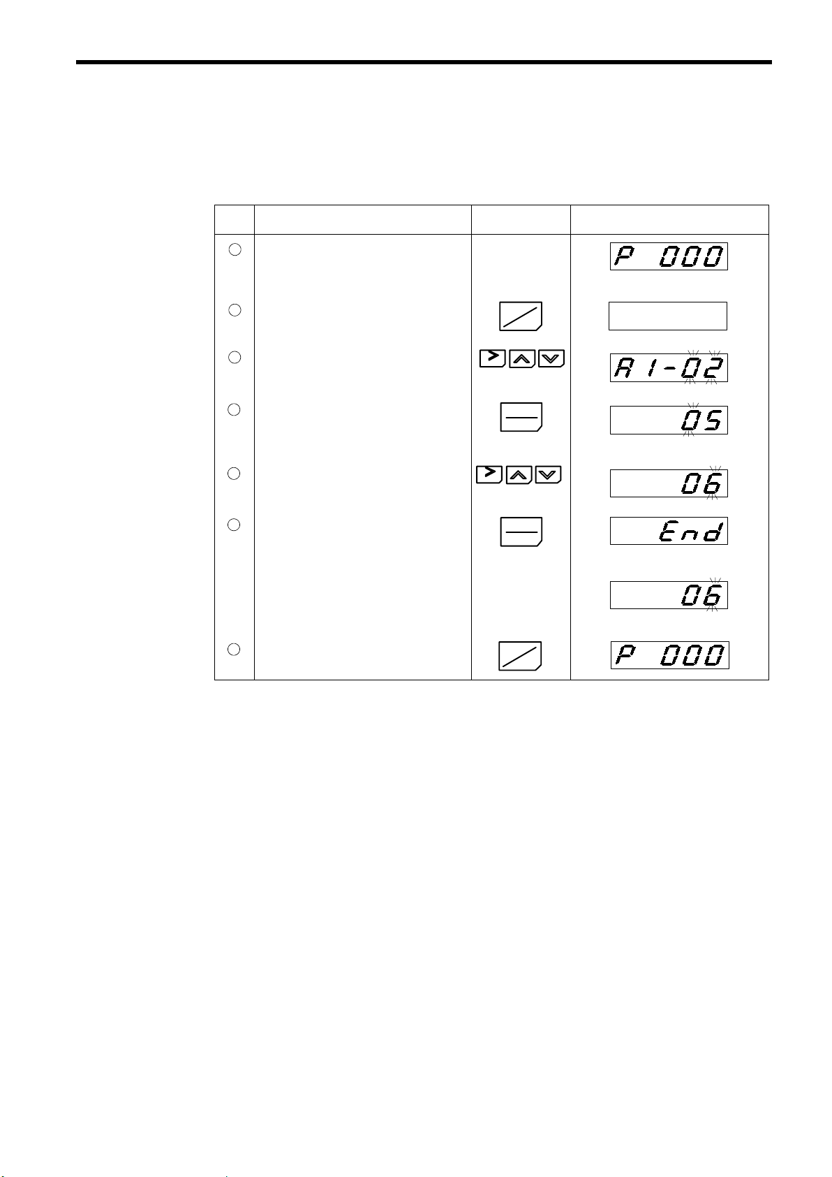
(a) Control Method Selection
The following procedures show how to change the control method from open loop vector
to flux vector.
Table 10 Control Method Selection/Change
Step Description Key Sequence Digital Operator Display
Power ON
1
• Displays speed reference value.
REMOTE LEDs (SEQ, REF) ON
G
Control method selection
2
• Move to program mode.
3
4
5
6
7
• Move to control method selection
• Verify the set value.
• Change to flux vector.
• Write-in the value.
Return to drive mode.
(A1-02).
RESET
RESET
DRIVE
PRGM
DATA
ENTER
DATA
ENTER
DRIVE
PRGM
Constant No. display
(Initial setting: open loop vector)
Displays for 0.5 seconds.
Setting completed.
G
43
Page 43

(b) Setting Motor Constants
CAUTION
S Be sure to set the motor constants before the initial operation and after replacement of the
motor. Reconfirm the motor constants after they have been set.
Failure to observe this caution may result in motor malfunctions such as sudden acceleration.
S In the following cases when under flux vector control, be sure to adjust the PG zero-pulse
as described in 4.3 (3) (e) PG Zero-pulse Adjustment:
• Before initial operation.
• After replacing the motor.
• After replacing the PG.
Set the motor constants in accordance with the values listed on the motor nameplate.
If the open loop vector control is selected, set
the motor constants in the order shown in
Table 11.
If the flux vector control is selected, set the
motor constants in the order shown in Table
12.
If the setting of the motor capacity selection
(E1-02) is changed, the motor constants will
Main Nameplate
VARISPEED-686SS5
3-PHASE PERMANENT MAGNET MOTOR
TYPE
PROTECTION
kW V
E1-03
E1-03
INS. COOLANT TEMP. ALTITUDE
STD
BRG NO
SER NO YEAR
YASKAWA ELECTRIC CORPORATION
Hz
POLES E1-05
COOLING
RATING A
E1-04
E1-04
MASS
r/min
E1-06, 07
E1-07
kg
JAPAN
m_C
return to their initial values.
Fig. 20 Example of Motor Nameplate
Table 11 Motor Constants Setup for Open Loop Vector Control
Constant
No.
A1-01 Constant access level 4
A1-02 Control method selection 5 5: Open loop vector control
E1-02 Motor capacity selection See remarks. Refer to Table A-6 Motor Capacity Selection List in Appendix
Name Set Value
(On Nameplate)
Remarks Checked
4.
PARAMETER
R
1
E1-09
Ld
E1-10
Lq
E1-11
E1-13
Ke
nθ
C2-12, 13
Ki
C3-02
Kt
C3-03
Si
B3-03
E1-03 Motor rated voltage (V) If two values for (V) are shown on the nameplate, set E1-03 to
the value in the lower row.
E1-04 Motor rated current (A) If two values for (A) are shown on the nameplate, set E1-04 to
the value in the lower row.
E1-05 Number of motor poles (POLES) If (POLES) is not shown on the nameplate, set E1-05 to 6.
E1-06 Motor max. speed (r/min) or (min-1) If two values are shown for (r/min) or (min-1), set E1-06 to the
value in the upper row.
E1-07 Motor base speed (r/min) or (min-1) If two values are shown for (r/min) or (min-1), set E1-07 to the
value in the lower row.
E1-08 Motor min. speed 10% of the base
Initial setting: 10% of base speed.
speed or higher
E1-09 Motor armature resistance (R1)
E1-10 Motor d-axis inductance (Ld)
44
Page 44

4 OPERATION
Constant
No.
E1-11 Motor q-axis inductance (Lq)
E1-13 Induced voltage (Ke)
C2-12 Leading phase compensation
Name
(On Nameplate)
(∆θ)
amount
E1-14 Variable torque/constant torque
selection
See remarks. If the motor model starts with SSR, E1-14 = 0.
If the motor model starts with SST, E1-14 = 1.
Table 12 Motor Constants Setup for Flux Vector Control
Constant
No.
A1-01 Constant access level 4
A1-02 Control method selection 6 6: Flux vector control
E1-02 Motor capacity selection See remarks. Refer to Table A-6 Motor Capacity Selection List in Appendix
E1-03 Motor rated voltage (V) If two values for (V) are shown on the nameplate, set E1-03 to
Name Set Value
(On Nameplate)
Remarks Checked
4.
the value in the lower row.
CheckedRemarksSet Value
E1-04 Motor rated current (A) If two values for (A) are shown on the nameplate, set E1-04 to
the value in the lower row.
E1-05 Number of motor poles (POLES) If (POLES) is not shown on the nameplate, set E1-05 to 6.
E1-06 Motor max. speed (r/min) or (min-1) If two values are shown for (r/min) or (min-1), set E1-06 to the
value in the upper row.
E1-07 Motor base speed (r/min) or (min-1) If two values are shown for (r/min) or (min-1), set E1-07 to the
value in the upper row.
E1-08 Motor min. speed Any value
Initial setting: 30 min
-1
between 0 and
the base speed
E1-09 Motor armature resistance (R1)
E1-10 Motor d-axis inductance (Ld)
E1-11 Motor q-axis inductance (Lq)
E1-13 Induced voltage (Ke)
C2-13 PG zero-pulse compensation
(∆θ) If the PG zero-pulse is adjusted, the set value of C2-13 changes.
amount
E1-14 Variable torque/constant torque
1
selection
Motor speed detection check
Check if the motor speed is detected correctly as explained in
4.3 (3) (d).
PG zero-pulse adjustment
Adjust the PG zero-pulse as explained in 4.3 (3) (e).
45
Page 45

The following procedures show how to change variable torque motor selection to
constant torque motor selection and set the motor related constants.
Table 13 Motor Related Constants Setting
Step Description Key Sequence Digital Operator Display
Power ON
1
• Displays speed reference value.
REMOTE LEDs
G
(SEQ, REF) ON.
Move to program mode.
2
When inputting the values other than motor
nameplate values, execute steps
low.
3
4
5
6
7
• Move to access level (A1-01).
• Verify the set value.
• Change to ADVANCED.
• Write-in the value.
• Return to constant No. display.
to be-
7
3
RESET
RESET
DRIVE
PRGM
DATA
ENTER
DATA
ENTER
DSPL
Constant No. display
Displays for 0.5 seconds.
Setting completed.
Variable torque/constant torque motor selection
8
• Move to variable torque/constant torque
motor selection (E1-14).
9
10
11
12
• Verify the set value.
• Select constant torque motor.
• Write-in the value.
• Return to constant No. display.
RESET
DATA
ENTER
(Initial setting: variable torque motor)
RESET
DATA
ENTER
Displays for 0.5 seconds.
Setting completed.
DSPL
(Cont’d)
46
Page 46

4 OPERATION
Step
13
Motor capacity selection setting
• Move to motor capacity selection (E1-02).
14
15
16
17
18
• Verify the set value of motor capacity
selection.
• Set correct value.
(Refer to Table A-6 for the set value of
motor capacity selection.)
• Write-in the value.
• Return to constant No. display.
Motor rated current setting
• Move to motor rated current (E1-04).
Description Key Sequence Digital Operator Display
RESET
DATA
ENTER
(Example: 200V 1750 min-17.5kW)
RESET
(Example: 200V 1450 min-17.5kW)
DATA
ENTER
Displays for 0.5 seconds.
Setting completed.
DSPL
RESET
19
• Verify the set value.
DATA
ENTER
G
(Example: 200V 1450 min-17.5kW)
20
21
• Set rated current according to value on
motor nameplate.
• Write-in the value.
RESET
G
DATA
ENTER
Displays for 0.5 seconds.
G
Setting completed.
22
23
• Return to constant No. display.
• Repeat the same procedures for
18to21
DSPL
as
GGG
GGG
for E1-09, 10, 11, 13.
(Add C2-12 setting in open loop vector
control.)
Furthermore, when using a special motor,
set motor base min
maximum min
24
• Return to constant No. display.
-1
(E1-07) and motor
-1
(E1-06).
DSPL
Return to drive mode.
25
DRIVE
PRGM
G
47
Page 47
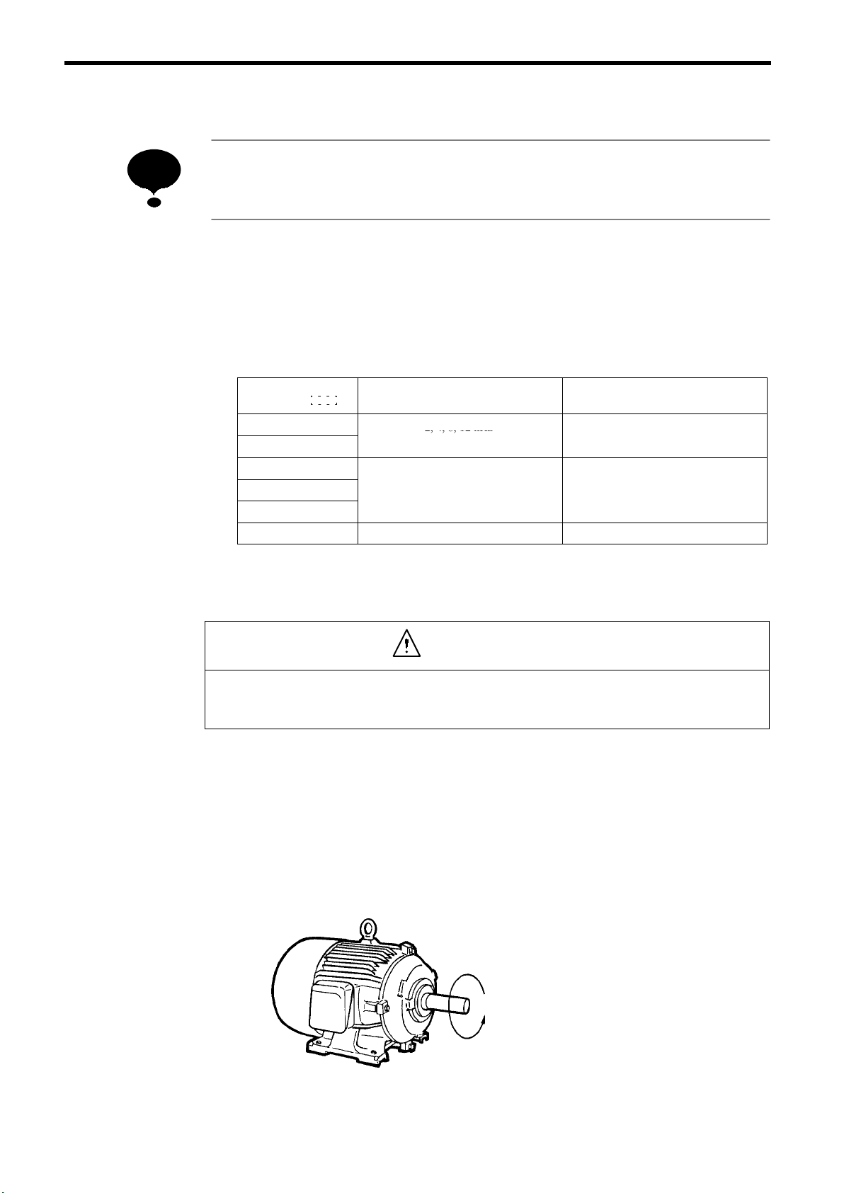
(c) Setting the Carrier Frequency
2,4,8,12kHz
g
High←Magnetic
noise→Low
NOTE
When changing the carrier frequency, contact your YASKAWA representative. To reduce
noise level by increasing the carrier frequency, it will be necessary to lower the rated current.
To reduce the motor noise during operation, change the setting of constant C6-02 (carrier
frequency selection). Note that this is not possible for all types of inverters. Table 14
shows whether or not noise reduction is possible by changing the setting of C6-02. Carrier frequency is set at 2 kHz at the factory.
The setting range of the carrier frequency is indicated in Table 14.
Table 14 Setting the Carrier Frequency
Inverter Model
CIMR-SSA
20P4 to 2018
40P4 to 4030
2022 to 2075
4037 to 4075
4110 to 4160
4185 to 4300 Only 2 kHz can be set.
*Carrier frequency lower limit is 2.0 kHz.
Setting Range of Carrier Frequency * Remarks
2, 4, 8, 12 kHz
High ← Magnetic noise → Low
2, 4, 8 kHz
h ← Magnetic noise → Low
Hi
12 kHz cannot be set.
(d) Checking the Motor Speed Detection (For Flux Vector Control)
CAUTION
S Verify that digital operator STOP LED is ON before checking motor speed detection.
S Verify that nothing is caught on the shaft or coupling.
When the control method is flux vector, select motor speed display on the digital operator
display and check the followings as shown in Table 15.
S Turn the motor shaft manually and verify that display of motor rotation direction
and polarity is correct.
S Motor speed is displayed correctly.
Forward run: Clockwise as viewed from the opposite load side (standard setting).
See Fig. 21.
Forward Run
Load Side
Fig. 21 Motor Rotation Direction
48
Page 48

4 OPERATION
Table 15 Checking the Motor Speed Detection
Step Description Key Sequence Digital Operator Display
Power ON
1
• Displays speed reference value.
Change the display to motor speed.
2
Turn the motor shaft counterclockwise as
3
viewed from the load side. (If the motor is
supposed to rotate clockwise in a forward operation, turn the motor shaft clockwise as
viewed from the load side.)
Turn the motor shaft clockwise as viewed
4
from the load side. (If the motor is supposed
to rotate counterclockwise in a forward operation, turn the motor shaft clockwise as viewed
from the load side.)
REMOTE LEDs (SEQ, REF) ON.
DSPL
(Ex.)
Make sure the displayed rotation direction
is forward and the displayed motor speed
corresponds to the present rotating speed.
(Ex.)
Make sure the displayed rotation direction
is reverse and the displayed motor speed
corresponds to the present rotating speed.
G
G
G
G
(%)
(%)
(%)
Return the display to speed reference value.
5
DSPL
Depress four times.
G
In case of motor speed malfunctions, refer to the table below for corrective actions.
Fault Contents Corrective Actions
• If the motor is supposed to rotate counterclockwise in a forward operation, set F1-05 = 1.
Motor speed displays in reverse polarity.
Motor speed displays 0 or other incorrect value.
• If the motor is supposed to rotate clockwise in a forward operation, set F1-05 = 0.
• Connect the PG cable to the correct terminal.
(Refer to page 22.)
Connect the PG cable to the correct terminal.
(Refer to page 22.)
(e) PG Zero-pulse Adjustment (For Flux Vector Control)
WARNING
S When adjusting PG zero-pulse, disconnect the motor from the machine.
The motor rotates automatically during adjustment.
S When PG zero-pulse adjustment is completed, “End” is displayed on the digital operator.
Do not touch it until it has come to a complete stop.
The motor starts and stops repeatedly when adjustments are made.
CAUTION
S Confirm safety.
• Is the motor disconnected from the machine?
• Is the lock key disconnected from the machine?
• Are there any persons or objects near the motor shaft?
• Has the motor come to a complete stop?
49
Page 49

NOTE
Adjust zero-pulse when replacing PG or motor (i.e. when relative position of connection between motor and PG).
The operation pattern below shows PG zero-pulse adjustment method. If an error is displayed during adjustment, refer to APPENDIX 5.
1
2
3
Forward Run
at Low Speed
(30 min
Power ON Adjustment Start
Pre-adjustment
Fig. 22 Operation Pattern of PG Zero-pulse Adjustment
Table 16 PG Zero-pulse Adjustment
Step Description Key Sequence Digital Operator Display
Power ON
1
• Displays speed reference value.
4
5
Forward Run
-1
)
at Low Speed
-1
(30 min
)
Automatic Operation
Adjustment Complete
Processing after
Adjustment
G
REMOTE LEDs (SEQ, REF) ON.
A1-02=06 (Control method: flux vector)
50
Pre-adjustment
2
• Move to program mode.
• Move to tuning item selection (T1-03).
• Verify the set value. (Go to : for “01.”)
• Change the value to “01” (adjusting of PG
zero-pulse only).
• Write-in the value.
RESET
RESET
DRIVE
PRGM
DATA
ENTER
DATA
ENTER
Constant No. display
Displays for 0.5 seconds.
(Cont’d)
Page 50

4 OPERATION
Step
:
Description Key Sequence Digital Operator Display
Setting completed.
• Return to constant No. display.
• Move to tuning mode (T1-02).
• Verify the set value.
• Change the value to “02” (tuning mode).
• Write-in the value.
DSPL
RESET
DATA
ENTER
RESET
DATA
ENTER
Displays for 0.5 seconds.
Setting completed.
Adjustment start
3
• Return to drive mode.
DRIVE
PRGM
RUN
Automatic adjustment during blinking
Adjustment completed
4
Adjustment completed.
Note: After verifying the set value of C2-13, write the value in Table A-7 in APPENDIX 5.
Displays for 2 seconds.
G
51
Page 51

(4) Jog Operation
The operation pattern below shows jog operation by using digital operator. The numbers in
the diagram correspond to the step numbers in Table 17.
2
1
3
10%
Forward Run
4
Reverse Run
10%
Power ON
Reverse Run
Command
Forward Jog Run
Reverse Jog Run
Fig. 23 Operation Sequence by Using Digital Operator (Jog Operation)
Table 17 Jog Operation by Using Digital Operator
Step Description Key Sequence Digital Operator Display
Power ON
1
• Displays speed reference value.
Operation Condition Setting
• Select LOCAL mode.
Forward jog run (10%)
2
• Perform jog run. (Runs while depressing
JOG key. Motor rotates at low speed.)
Depress the key for 2 seconds or longer
to check the operation.
REMOTE LEDs (SEQ, REF) ON.
LOCAL
REMOTE
REMOTE LEDs (SEQ, REF) OFF
JOG
G
G
FWD LED ON
REV LED OFF
G
FWD LED ON
REV LED OFF
52
Reverse run command
3
• Switch to reverse run.
Reverse jog run (10%)
4
• Perform jog run. (Runs while depressing
JOG key. Motor rotates at low speed.)
Note: When the constant b1-05 (Operation selection for setting of E1-08 or less) = 1 (base block) and
the constant E1-08 is set to 30 min
-1
or more, reset E1-08 to 0 and then adjust the PG zero-pulse.
FWD
REV
FWD LED OFF
REV LED ON
JOG
FWD LED OFF
REV LED ON
After adjusting the PG zero-pulse, return the constant E1-08 to the previous setting.
G
G
Page 52

(5) Example of Basic Operation
4 OPERATION
NOTE
Check the following items during operation.
V Motor rotates smoothly.
V Motor rotates in the correct direction.
V Motor does not have abnormal vibration or noise.
V Acceleration and deceleration are smooth.
V Current matches the load flow.
V Status indicator LEDs and digital operator display are correct.
(a) Operation by Digital Operator
The diagram below shows a typical operation pattern using the digital operator. The
numbers in the diagram correspond to the step numbers in Table 18.
56 7
Forward
100%
1
Power
ON
Forward Jog Run Speed Setting
2
10%
3
4
Forward
25%
Forward Run
Reverse Run
Reverse
SpeedReferenceValueChange
Stop
100%
Fig. 24 Operation Sequence by Digital Operator
53
Page 53

Table 18 Typical Operation by Digital Operator
Step Description Key Sequence Digital Operator Display
Power ON
1
• Displays speed reference value.
G
Operation condition setting
• Seslect LOCAL mode.
Forward jog run (10%)
2
• Perform jog run. (Runs while depressing
JOG key. Motor rotates at low speed.)
Speed Setting
3
• Displays speed reference value.
• Change the value.
• Write-in the value.
• Select motor speed monitor display.
Forward run
4
• Perform forward run. (25%)
RUN
Motor rotates by de-
pressing RUN key.
LOCAL
REMOTE
JOG
Change the value
by depressing
RESET
DATA
ENTER
DSPL
RUN
REMOTE LED (SEQ, REF) ON
G
G
G
G
(Displays for 2 seconds.)
G
G
RUN LED ON FWD LED ON
Speed reference value change (25% → 100%)
5
• Select speed reference value display.
• Change the value.
• Write-in the value.
(Motor min
-1
increases.)
• Select motor speed monitor display.
Reverse run
6
• Switch to reverse run.
Motor decelerates to stop. Then reverse
run startrs at set min
Stop
7
-1
of 100%.
• Decelerates to stop.
DSPL
Depress 4 times.
Change the value
by depressing
RESET
DATA
ENTER
DSPL
FWD
REV
STOP
G
G
Digit to be changed blinks.
G
(Displays for 2 seconds.)
G
G
REV LED ON
G
STOP LED ON
(RUN LED blinks during deceleration.)
54
Page 54

4 OPERATION
(b) Operation by Control Circuit Terminal Signal
The diagram below shows a typical operation pattern using the control circuit terminal
signals. The numbers in the diagram correspond to the step numbers in Table 19.
4
1
2
3
Forward Run
100%
Power ON
Speed Reference
Operation
Stop
Setting
Fig. 25 Operation Sequence by Control Circuit Terminal Signal
Table 19 Typical Operation by Control Circuit Terminal
Step Description Key Sequence Digital Operator Display
Power ON
1
• Displays speed reference value.
Speed reference setting
2
• Input speed reference voltage by control
• Switch to motor speed display.
Forward run command
3
• Close between control circuit terminals 1
circuit terminal 13 or 14 and verify the input value on the digital operator.
and 11 to perform forward run.
REMOTE LED (SEQ, REF) ON
DSPL
RUN LED ON FWD LED ON
G
G
Voltage: 10V
G
G
RUN
Stop
4
• Open between control circuit terminals 1
and 11 to stop operation.
(RUN LED blinks during deceleration.)
STOP LED ON
STOP
55
Page 55

5 SETTING OPERATION CONDITIONS
5.1 DIGITAL OPERATOR KEY DESCRIPTION
DRIVE FWD REV REMOTE
Operation Mode Selection Key
Selects the REMOTE and LOCAL (digital operator)
mode alternately.
Operation Command Keys
Used to operate the inverter by the digital operator.
They are valid only in the drive mode.
JOG: Jog run is possible while JOG key is held pressed.
FWD/REV: Selects forward or reverse run alternately.
RUN: Red LED lights when RUN is depressed.
(Refer to Fig. 27.)
STOP: Red LED lights when STOP is depressed.
(Refer to Fig. 27.)
DRIVE FWD REV
DIGITAL OPERATOR
JVOP-132
LOCAL
REMOTE
DRIVE
JOG
FWD
REV
RUN STOP
SEQ
PRGM
REMOTE
ENTER
RESET
DSPL
DATA
Mode Indicator LEDs
(All LEDs blink if a fault occurs in the drive mode.)
Drive Mode Display
Lights when the drive mode is selected.
OFF when the program mode is selected.
Rotating Direction Display
FWD:Lights at forward run.
:
REV
Lights at reverse run.
Remote Mode Display
Lights in operation mode using the signals input
from the control circuit terminals or option cards.
SEQ:Lights when the remote mode is selected
for the run command.
REFSEQ
REF : Lights when the remote mode is selected
for the frequency reference.
Display
Displays set values of each function or monitoring
values such as speed and output current. (5 characters)
Mode Selection Key
Selects the drive mode and the program mode
alternately. (Mode selection is possible even
during operation.) When the drive mode is selected, DRIVE LED lights.
Display Selection Key
Selects the data to be displayed in predetermined
sequence. (Display sequence is shown in Table 21.)
Read/Write Key
Displays the set values of the constants. Depress-
ing this key again after setting a value enters it.
Numeral Change Key
Changes set values or constant numbers.
<
: Increment key
>
: Decrement key
Digit Selection Key
Selects the digit of a set value to be changed.
The selected digit blinks. (This key also
used as the reset key if a fault is displayed.)
56
Fig. 26 Digital Operator Key Description
RUNand STOP LEDs light, blink, and go OFF depending on the status of operation.
RUN
Key
Key
STOP
Internal Run
Command
STOP
RUN
Speed
Reference
Motor
Reference
RUN LED
STOP LED
:
ON
: Blink
*
: OFF
* LED goes OFF at flux vector control.
Fig. 27 Run and Stop LED Display
STOP
Page 56

5.2 DIGITAL OPERATOR MODE SELECTION
This section describes the digital operator modes of the VS-686SS5.
(1) Modes
The VS-686SS5 is equipped with 3 modes as shown in the following table.
Table 20 Digital Operator Modes
Mode Primary Functions
Drive Mode The inverter can be run in this mode.
Use this mode when monitoring values such as frequency references or output current,
displaying fault information, or displaying the fault history.
Program Mode Use this mode when setting/reading the constants required for operation. Constants of
groups U, A, b, C, d, E, F, H, L, o, T can be accessed.
Modified Constants Mode Use this mode to set/read constants that have been changed from their factory-set values.
5 SETTING OPERATION CONDITIONS
(2) Switching Modes
Drive mode or program mode is selected by depressing [DRIVE/PRGM] key. The DRIVE
LED lights when drive mode is selected, and goes OFF when program mode is selected.
Constants display and settings in each mode can be changed by depressing [
∧], [∨]or[> RE-
SET] key. Depress [DATA/ENTER] key to write-in the constants.
Modified constants mode can be accessed from drive mode by depresssing [> RESET] and
[DRIVE/PRGM] keys simultaneously. Depress [DRIVE/PRGM] key to return to drive mode.
These are the basic operation steps.
The example below shows the operation using digital operator for each mode. Constants
A1-01 (display in program mode) and E1-08 (display in modified constants mode) differ depending on user setting.
Power ON
DRIVE
PRGM
DRIVE
PRGM
Drive Mode
RESET
G
DRIVE
PRGM
DRIVE
+
PRGM
Program Mode
Modified Constants Mode
57
Page 57

Drive mode and program mode can be changed by the digital operator even during operation.
DSPL
5
Even if the mode is changed to the program mode to set/read constants during operation, the
inverter continues operation. The inverter does not operate even if the run command is input,
when the program mode is selected.
When the constants are set/read during operation, depress [DRIVE/PRGM] key and then
[DATA/ENTER] key to return to the speed reference value display (the same as power-ON
display).
5.3 DRIVE MODE
The inverter can operate in this mode. Run data display and fault display are possible.
Each time the display selection key is depressed, the item to be monitored is changed. At an occurrence of a fault, the digital operator enters the fault display mode automatically. The display mode
returns to the one selected previously by depressing [> RESET] key.
Table 21 Typical Operation in Drive Mode
Description Key Sequence Digital Operator Display
Power ON
Speed Reference
Motor Speed
Output Current
Output Voltage
U Constants
*1 The first item to be displayed after power ON can be selected from speed reference value, motor speed, output current,
and display item set in o1-01 by setting an appropriate value for o1-02.
*2 A speed reference value can be set by using [∧], [∨]or[> RESET] key.
*3 Instead of the output voltage, item to be displayed from U1 constant can be selected by setting o1-01.
*4 Select the U constant to be displayed by using [∧], [∨]or[> RESET] key.
*5 The U constant selected previously is displayed.
*1
*2
DSPL
DSPL
DSPL
*3
DSPL
*4
DSPL
G
G
G
G
*5
58
Page 58

5 SETTING OPERATION CONDITIONS
(1) Changing Speed Reference Value
[Example]
Changing the speed reference value from 0.00% to 100.0% in the LOCAL and drive modes.
Table 22 Changing the Speed Reference Value
Step Description Key Sequence Digital Operator Display Remarks
Display the speed reference value.
1
DSPL
G
Change the value to “100.0%”.
2
Write-in the set value.
3
RESET
DATA
ENTER
G
G
The value to be set blinks.
Display stops blinking for 2 seconds.
Display starts blinking again.
G
(2) Monitor Display
[Example]
Monitoring DC bus voltage (U1-07) during speed reference display.
Table 23 Typical Monitor Display Operation
Step Description Key Sequence Digital Operator Display Remarks
Displaying the speed reference value.
Display U constant.
1
DSPL
Depress 4 times.
G
U constant selected previously is displayed.
Select U1-07.
2
Display monitored value.
3
Return to constant No. display.
4
Return to speed reference display.
5
RESET
DATA
ENTER
DSPL
DSPL
Depress 4 times.
G
59
Page 59

(3) Fault Display
When the VS-686SS5 detects a fault, the fault is displayed on the digital operator and activate
the fault contact output and the motor coasts to a stop. Refer to Table 31 for the fault and the
display at fault occurrence.
Since the VS-686SS5 stores the information obtained at fault occurrence in the inverter, the
information can be verified. For details, refer to Table A-4.
[Example]
Verifying the status at fault occurrence (speed reference, motor speed, output current in the
example) and resetting the fault when overcurrent occurs during operation at 50% speed.
Table 24 Typical Operation of Fault Display
Step Description Key Sequence Digital Operator Display Remarks
Motor rotating at 50% speed.
G
Overcurrent occurs. Displays the fault.
Move to program mode.
1
Verify the speed reference at fault
2
occurrence.
DRIVE
PRGM
RESET
Verify the value.
3
Return to constant No. display.
4
Verify the motor speed at fault occur-
5
rence.
Verify the value.
6
Return to constant No. display.
7
Verify the output current at fault oc-
8
currence.
Verify the value.
9
10
Return to constant No. display.
Return to drive mode.
11
Reset the fault.
12
RESET
RESET
DATA
ENTER
DSPL
DATA
ENTER
DSPL
DATA
ENTER
DSPL
DRIVE
PRGM
RESET
G
G
G
By resetting the fault, the display en-
G
tered just prior to the fault occurrence is returned.
60
NOTE
Fault reset cannot be activated while forward/reverse run signal from control circuit terminal
is ON. Turn OFF the signal and check the safety of the sorrounding area, then reset the inverter.
Page 60

5.4 INITIALIZE MODE
As described below, the access level to set/read constants or control method can be selected. Set
initialize mode constants before use of the VS-686SS5.
The following table shows the constants for initialize mode.
Table 25 Initialize Mode
5 SETTING OPERATION CONDITIONS
Constant
No.
A1-01
A1-02 Control metod
A1-03 Initialize
A1-04 Password 1 (for input) For future use (Do not set because of special function.)
Access level
(change enable during run)
Name Description
0 : Exclusive for monitoring
A1-01 can be set/read and U constants in QUICK-STARTlevel can be read.
2 : QUICK-START
Constants required for quick-start operation can be set/read.
3 : BASIC
Constants required for basic operation can be set/read.
4 : ADVANCED
Constants required for advanced operation can be set/read.
5 : Open loop vector
6 : Flux vector
Constant initialization
2220 : 2-wire sequence
(Returns to the value set at the factory prior to shipment.)
3330 : 3-wire sequence
61
Page 61
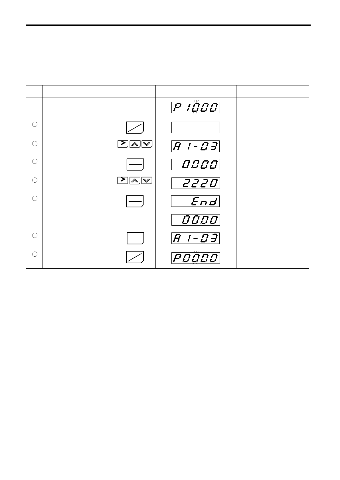
Constant Initialization
All the constants are returned to the initial setting by initialization. Several constants such as motor
constants cannot be initialized. For details, refer to APPENDIX 4.
Table 26 Constant Initialization
Step Description Key Sequence Digital Operator Display Remarks
Displaying speed reference
G
Move to program mode.
1
Select A1-03.
2
Display the set value.
3
Input 2220.
4
Write-in the value.
5
Return to constant No. display.
6
Return to drive mode.
6
RESET
RESET
DRIVE
PRGM
DATA
ENTER
DATA
ENTER
DSPL
DRIVE
PRGM
Constant No. display
G
Displays the constant No. selected
formerly.
Displays for 0.5 seconds.
Display return to 0.
Speed reference return to 0.
62
Page 62

5.5 PROGRAM MODE
<
The constants of the VS-686SS5 are composed of group symbols, function numbers and serial numbers for each function item as shown below. Use [
symbol, function number or serial number and select one by [DATA/ENTER] key. For details of
the constants, refer to APPENDIX 4 or Descriptive Manual for Constants.
Constant No.
-15
jj
5 SETTING OPERATION CONDITIONS
]or [>] key to change the display of group
Serial No. for each
function item
Function No.
Group
U Monitor constants
A Initialize constants
b Application-related constants
C Adjustment constants
d Speed reference-related constants
E Motor-related constants
F Option-related constants
H Control circuit terminal-related constants
L Protection-related constants
o Digital operator-related constants
T Tuning-related constants
[Example]
Select BASIC or ADVANCED and change the deceleration time (C1-02) from 10.0 to 20.0 seconds.
Table 27 Changing Constant Data
Step Description Key Sequence Digital Operator Display Remarks
Displaying speed reference
G
Move to program mode.
1
Select C1-02.
2
Display set value.
3
Change the value.
4
Write-in the value.
5
Displays the set value.
6
Return to constant No. display.
7
Return to drive mode.
8
RESET
RESET
DRIVE
PRGM
DATA
ENTER
DATA
ENTER
DSPL
DRIVE
PRGM
Constant No. display
G
G
G
G
Displays the constant No. selected
formerly.
Displays for 0.5 seconds.
Returns to display before write-in.
63
Page 63

5.6 MODIFIED CONSTANTS MODE
Compares the constant values preset at the factory with the values changed by the user, and displays
the constants changed from the preset constants automatically. In this mode, constants can be read;
in addition, they can also be set or changed.
[Example]
Read the constants C1-01 (acceleration time 1) and E1-01 (input voltage) when the factory settings
have been changed. In addition, change the setting of E1-01 (input voltage) from 220V to 230V
in this mode.
Table 28 Typical Operation in Modified Constants Mode
Step Description Key Sequence Digital Operator Display Remarks
Power ON
Switch to REMOTE mode.
1
Select modified constants mode.
2
Verify the set value.
3
Return to constant No. display.
4
Display the next-to-be-changed
5
constant.
Verify the set value.
6
Change the value.
7
Write-in the value.
8
RESET
RESET
LOCAL
REMOTE
DRIVE
DATA
ENTER
DSPL
DATA
ENTER
DATA
ENTER
PRGM
G
REMOTE LED ON
DRIVE LE
D blinks.
Modified constants mode can be accessed from drive mode by depressing [RESET] and [DRIVE/PRGM]
keys simultaneously. Verify that
DRIVE LED is blinking.
G
G
Displays for 0.5 seconds.
64
Displays the set value.
9
10
Return to constant No. display.
11
Return to drive mode.
DSPL
DRIVE
PRGM
G
G
Page 64

6 MAINTENANCE AND INSPECTION
WARNING
S
Never touch high-voltage terminals in the inverter.
Failure to observe this warning can result in an electric shock.
S
Replace all protective covers before powering up the inverter. To remove the cover,
make sure to shut OFF the molded-case circuit breaker.
Failure to observe this warning can result in an electric shock.
S
Perform maintenance or inspection only after verifying that the CHARGE LED goes OFF,
after the main circuit power supply is turned OFF.
The capacitors are still charged and can be dangerous.
S
Only authorized personnel should be permitted to perform maintenance, inspections or
parts replacement.
[Remove all metal objects (watches, bracelets, etc.) before operation.]
(Use tools which are insulated against electrical shock.)
Failure to observe this warning can result in an electric shock.
6 MAINTENANCE AND INSPECTION
CAUTION
S
The control PC board employs CMOS ICs. Do not touch the CMOS elements.
They are easily damaged by static electricity.
S
Do not connect or disconnect wires or connectors while power is applied to the circuit.
Failure to observe this caution can result in personal injury.
This chapter describes basic maintenance and inspection procedures for the VS-686SS5.
65
Page 65

6.1 PERIODIC INSPECTION
UnitM
The VS-686SS5 will function longer if it is kept clean, cool and dry, while observing the precautions
listed in Par. 2.3. Check for tightness of electrical connections, discoloration or other signs of
overheating or aging. Use Table 29 as your inspection guide. Before servicing, turn OFF AC main
circuit power and be sure that the CHARGE LED is OFF.
Table 29 Periodic Inspection
Component Check Corrective Action
External Terminals,
ountingBolts,
Connectors, etc.
Heatsink Build-up of dust and dirt
Printed Circuit Board Accumulation of conductive dust or oil.
Cooling Fan
Power Elements Accumulation of dust and dirt
Smoothing Capacitor Discoloration or odor Replace the capacitor or inverter unit.
Loose screws Tighten.
Loose connectors Tighten.
For abnormal noise and vibration.
Whether the cumulative operation time
exceeds 20,000 hours or not.
Blow with dry compressed air of 39.2¢104to
4
58.8¢10
Blow with dry compressed air of 39.2¢104to
58.8¢10
oil cannot be removed, replace the board.
Replace the cooling fan.
Blow with dry compressed air of 39.2¢104to
58.8¢10
Pa (4 to 6k g¡cm2) pressure.
4
Pa (4 to 6kg¡cm2) pressure. If dust and
4
Pa (4 to 6k g¡cm2) pressure.
6.2 PARTS REPLACEMENT SCHEDULE (GUIDELINES)
Replace the following parts periodically, for a long, safe, trouble free working life of VS-686SS5.
Table 30 Parts Replacement Schedule
Parts Interval (Approx.) Remarks
NOTE
Cooling Fan
Smoothing Capacitor
Breakers or Relays
Fuse
Aluminum Electrolytic
Capacitor on PC Board
Operating conditions are as follows:
Ambient temperature : 30_C yearly average
Load factor : 80% or below
Operation rate : 20 hours or below /day
2 to 3 years Replace with new one.
5 years
10 years Replace with new one.
5 years
Replace with new one. (Decided after
inspection.)
Decidedafterinspection.
Replace with new one. (Decided after
inspection.)
66
Page 66

7 TROUBLESHOOTING
)th
C
7 TROUBLESHOOTING
This chapter describes the inverter fault display and the fault contents caused by motor/machine malfunctions and the corrective actions to be taken.
7.1 FAULT DIAGNOSIS AND CORRECTIVE ACTIONS
When the VS-686SS5 detects a fault, the fault is displayed on the digital operator and activates the fault
contact output and the motor coasts to a stop. Check the cause in Table 31 and take the corrective
actions. If the inspections or corrective actions described cannot solve the problem, contact your
YASKAWA representative immediately.
To restart, turn ON the reset input signal or depress [>RESET] key or shut OFF the main circuit power
supply once, to reset the stop status.
Table 31 Fault Diagnosis and Corrective Actions
Fault Display Description Details Corrective Action Rank*
The main circuit DC voltage fell below
the undervoltage detection level while
Main circuit undervoltage
(UV1)
Pre-charge contactor open
(UV3)
Momentary powerloss(UV
Ground fault (GF)
Overcurrent (OC)
Overvoltage (OV)
Overspeed (OS)
Speed deviation (dEV)
running or decelerating and momentary
power loss ride-through time elapsed.
Detection level:
200 V class: Approx. 1 90 V or less
400 V class: Approx. 3 80 V or less
The pre-charge contactor opened while
running or decelerating.
• The main circuit DC voltage fell below
eundervoltagedetectionlevel.
• The pre-charge contactor opened.
Inverter output grounding current
exceeded 50% of inverter rated current.
The inverter output current exceeded the
OC level.
The main circuit DC voltage exceeded the
OV level.
Detection level:
200 V class: Approx. 406 V
400 V class: Approx. 812 V
The motor speed exceeded the overspeed
level (F1-08).
Detection time: F1-09
The inverter operates according to the set-
ting of constant F1-03
The deviation of the speed reference and
speed feedback exceeded the regulation
level (F1-10).
Detection time: F1-11
The inverter operates according to the set-
ting of constant F1-04
.
.
• Check the power supply wiring.
• Correct the line voltage.
• Check that motor insulation has not
deteriorated.
• Check that connection between inverter
and motor is not damaged.
• Check the motor coil resistance.
• Extend the accel/decel time.
• Check the motor insulation.
• Multi-meter check
• Extend the deceleration time.
• Add braking circuit.
Check the load. B
Check the load. B
(C during
stop)
A
A
A
A
A
(Cont’d)
67
Page 67
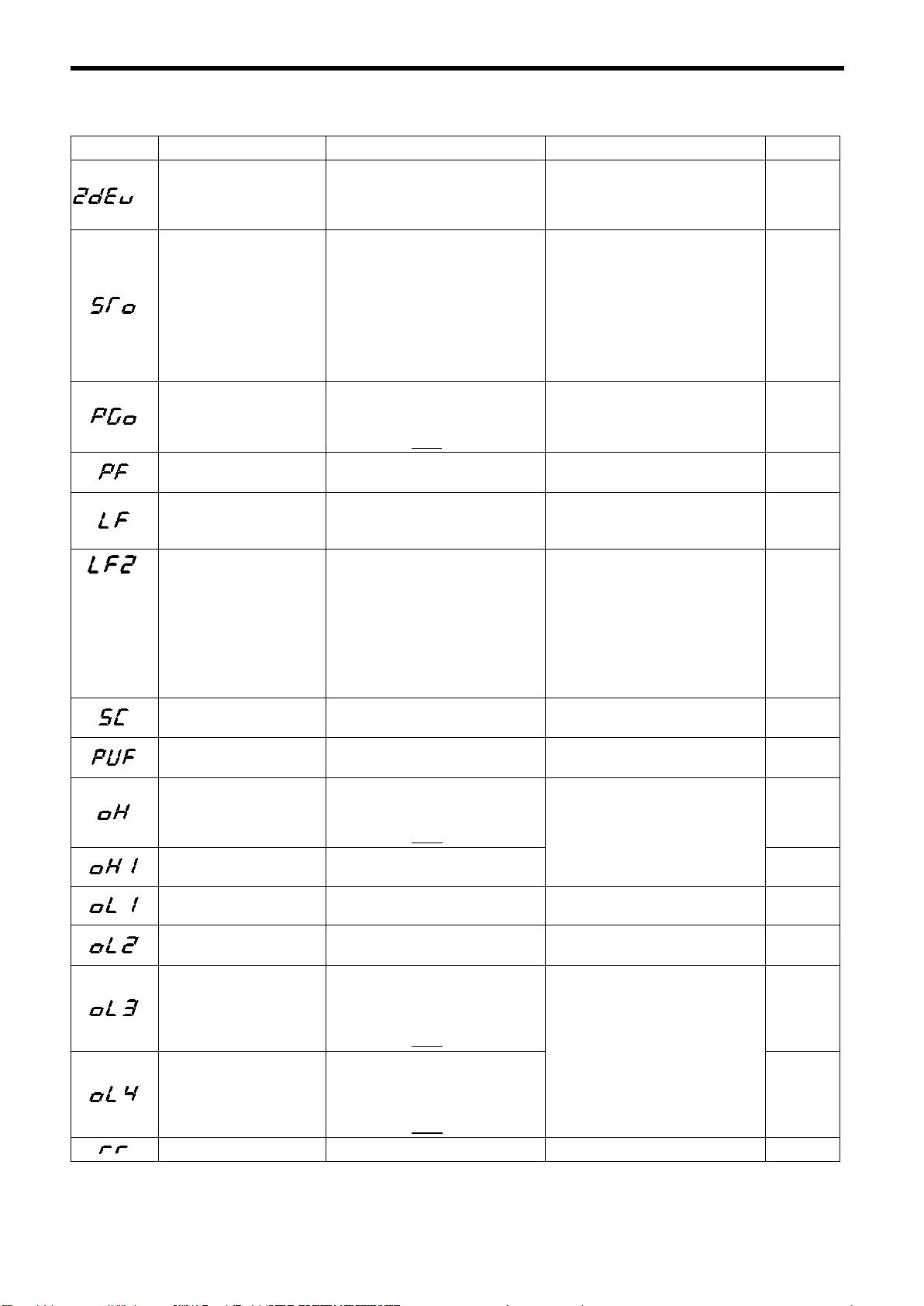
Table 31 Fault Diagnosis and Corrective Actions (Cont’d)
Checkthefil
Checktheload
Fault Display Description Details Corrective Action Rank*
• Excessive speed deviation caused by
*2
Phase Z pulse fault (ZdEV)
Step out (STO) Control is disabled by step out.
PG open circuit (PGO)
Excessive ripple in DC bus bar
voltage (PF)
Load open-phase (LF) Inverter output has open-phase.
Output current unbalance (LF2) A large unbalance occurred in the output
*4
Load short-circuit (SC) Inverter output (load) is short-circuited.
Fuse blown (PUF)
Inverter overheat alarm (OH)
Inverter overheat (OH1)
Motor overload (OL1)
Inverter overload (OL2)
Overtorque detection 1 (OL3)
Overtorque detection 2 (OL4)
Braking transistor fault (RR) The braking transistor has failed. Replace the inverter. A
phase Z error detection
• Malfunction caused by phase Z pulse
error or noise
The PG line is broken.
Detection time: F1-13
The inverter operates according to the set-
ting of constant F1-02
• Inverter input voltage has open-phase.
• Large unbalance in input voltage.
current because of one of the following
causes.
• The inverter output wiring is faulty.
• ASR gain setting is incorrect.
• Failure occurred with parts on the output
side of the inverter.
• Motor is faulty.
(Unbalanced impedance in motor)
• Main transistor was broken.
• DC circuit fuse was blown.
The transistor heatsink temperature
exceeded the allowable value (95°C).
The inverter operates according to the setting of constant L8-03
The transistor heatsink temperature
exceeded the allowable value (105°C).
Inverter output exceeded the motor
overload level.
Inverter output exceeded the inverter
overload level.
Torque exceeded overtorque detection
level 1 (L6-02).
Detection time: L6-03
The inverter operates according to the set-
ting of constant L6-01
Torque exceeded overtorque detection
level 2 (L6-05).
Detection time: L6-06
The inverter operates according to the set-
ting of constant L6-04
.
*3
.
.
.
• Check the PG wiring cable and connec-
tor.
• Readjust the zero-pulse.
• Check the motor constants. (Refer to
page 44.)
• Set the constant induced voltage
(E1-13) to a value that is 10% less than
that of Ke on the nameplate.
• Check the operating temperature of
the motor.
• Decrease ASR gain (C5-01).
• Decrease accel time (C1-01).
• Check the PG line.
• Check the condition of the motor lock or
the load.
• Check the line voltage.
• Re-tighten the input terminal screws.
• Check the output wiring.
• Check the motor impedance.
• Re-tighten the input terminal screws.
• Check the output wiring.
• Re-tighten the input terminal screws.
• Check the disconnection of the motor
coil.
• Decrease ASR proportional (p) gain 1
(C5-01).
• Replace the inverter.*5
• Replace the motor.*5
• Check the motor coil resistance.
• Check the motor insulation.
Check for damaged transistor, load side
short-circuit, grounding, etc.
• Check the heatsink and the ambient tem-
perature.
•
Reduce the load. A
• Reduce the load.
• Extend the acceleration time.
ter andthefan.
.
A
A
B
A
A
A
A
A
B
A
A
B
B
(Cont’d)
68
Page 68
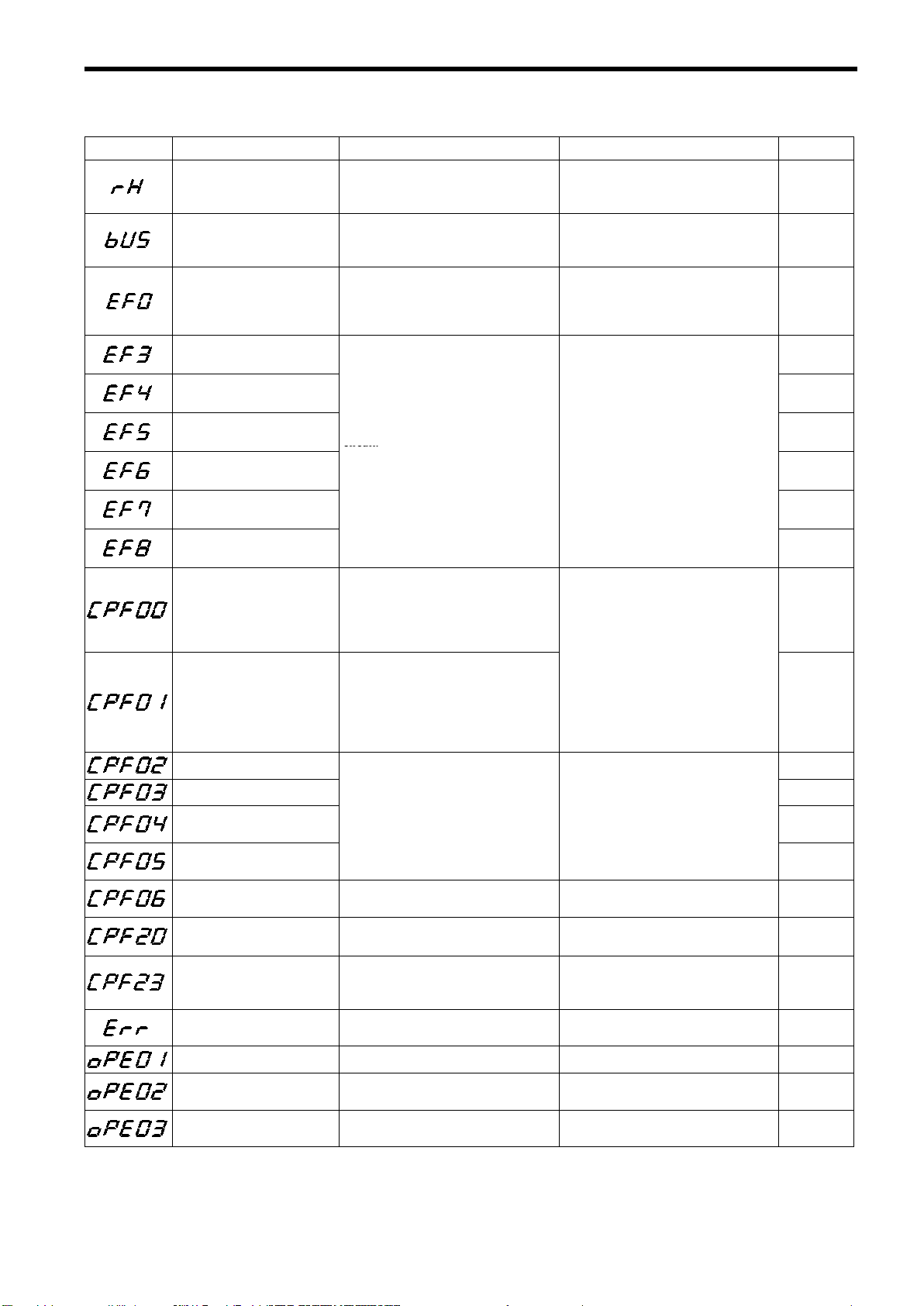
7 TROUBLESHOOTING
circuit.
Ifthefaultisdispl
l
i
Table 31 Fault Diagnosis and Corrective Actions (Cont’d)
Fault Display Description Details Corrective Action Rank*
Braking resistor unit overheat
(RH)
Transmission fault with transmission option (bUS)
External fault from transmission option (EF0)
External fault at terminal 3
(EF3)
External fault at terminal 4
(EF4)
External fault at terminal 5
(EF5)
External fault at terminal 6
(EF6)
External fault at terminal 7
(EF7)
External fault at terminal 8
(EF8)
Control circuit fault 1 (CPF00)
(Digital operator transmission
fault)
Control circuit fault 2 (CPF01)
(Digital operator transmission
fault)
Baseblock circuit fault (CPF02) A
The braking resistor unit temperature has
exceeded the allowable value.
(Protects only inverter built-in type)
Transmission fault with transmission option (detectedwhenthefault contirnued for
2.5 seconds)
External fault was input from the transmission option.
Fault occurred in the external control
circuit.
The inverter operates according to the settings of constants H1-01 to H1-06.
• Transmission between the inverter and
digital operator cannot be established 5
seconds after supplying power.
• MPU peripheral element check fault
(initial)
• Transmission between the inverter and
digital operator is established once after
supplying power, but later transmission
fault continues for more than 2 seconds.
• MPU peripheral element check fault
(initial)
Reduce the regenerative load. A
Check the transmission devices and the
transmission signals.
External fault, defined by user specification, was input from the transmission option. Find the external fault items from the
I/O list and correct it.
Check the condition of the input terminal.
not connected, replace the inverter.
• Insert the digital operator connector
again.
• Check the control circuit wiring.
• Replace the control card.
ayedwhen termina
s
A
B
B
B
B
B
B
B
A
A
EEPROM fault (CPF03) A
CPU internal A/D converter
fault (CPF04)
CPU external A/D converter
fault (CPF05)
Option card connection fault
(CPF06)
A/D converter fault in option
card (CPF20)
Cross-diagnose fault between
transmission option and control
card (CPF23)
EEPROM writing fault (Err)
kVA selection fault (OPE01) kVA selection fault Check and set the constant data. D
Constant setting range fault
(OPE02)
Multi-function contact input
selection fault (OPE03)
Inverter control unit fault. Replace the control card.
The option card is not installed correctly. Install the option card again. A
Option card (AI-14B/U) A/D converter
fault
Diagnosis data has not been updated for
more than 0.2 seconds between the transmission option and the control card.
EEPROM internal data did not match
when initializing the constant.
Constant data is out of range. Check the constant data settings. D
The same values are set except for F and
FF.
• Check the option card contact part.
• Replace the option card.
• Check the transmission option contact
part.
• Replace the transmission option.
Replace the control card. A
Check the function selection. D
(Cont’d)
A
A
A
A
69
Page 69

Table 31 Fault Diagnosis and Corrective Actions (Cont’d)
Fault Display Description Details Corrective Action Rank*
• C-option is not connected although run
Option reference selection
fault (OPE05)
Control method selection fault
(OPE06)
Multi-function analog input
selection fault (OPE07)
Multi-function input/output
selection fault (OPE08)
R/min setting fault (OPE10)
Energy-saving control
constants setting fault
Digital operator fault (OPr)
command from C-option is selected.
• C-option is not connected although fre−
quency reference from C-option is se−
lected.
PG contorl card is not connected during
flux vector control.
C-option is AI-14B and option/inverter
change is selected.
Any of the following setting faults has occurred:
• The setting unused in the control method
is selected for F4-01 and F4-04.
• The setting unused in the control method
is selected for F5-01 and F5-02.
• The setting unused in the control method
is selected for H1-01 to H1-06.
• The setting unused in the control method
is selected for H2-01 to H2-03.
• The setting unused in the control method
is selected for H3-05 and H3-09.
• The setting unused in the control method
is selected for H4-01 and H4-04.
• The setting unused in the control method
is selected for o1-01.
The settings of E1-06 to E1-08 do notsatisfy the following conditions:
E1-06 ≧ E1-07 ≧ E1-08
Energy-saving control constant values are
out of range.
The digital operator was disconnected during operation by run command from the
digital operator.
• Check and set the constant data.
• Connect the C-option.
Connect PG control card. D
Check and set the constant data. D
Check and set the constant data. D
Check and set the constant data. D
Check the motor nameplate values and inverter constants (E-constants) settings.
• Check the wiring cable and the digital
operator connection.
• Replace the control card.
D
D
A
*1: The ranks are classified as follows:
A : Major fault (Motor coasts to a stop, digital operator indicator lights, and fault contact
is output.)
B : Accordingto the constants for major/minor fault selection (constants underlined in the
table), major fault (Motor coasts to a stop or decelerates to a stop, digital operator indica
tor lights, and fault contact is output.) or minor fault (Rank C) can be selected.
C : Minor fault [Operation continues, digital operator indicator blinks, no fault contact is
output, and minor fault contact is output (when multi-function output is selected)].
D : Warning (Operation cannot be performed, digital operator indicator lights, no fault
contact is output, no minor fault contact is output.)
*2:
*3: A load of 30% or less may result in incorrect detection of the load.
*4: The display is applicable for software No. 1033 or later (FLASH side). To check which ver-
sion is being used, refer to U1-14.
*5: If replacing the motor, contact your YASKAWA representative.
is displayed for the fault trace (U2 constant) and fault record (U3 constant).
70
Page 70

7.2 MOTOR FAULTS AND CORRECTIVE ACTIONS
or
too
low
.
operation
If any of the following faults occurs in the motor, check the cause and provide the relevant corrective
action. If these inspections and corrective actions cannot solve the problem, contact your YASKAWA
representative immediately.
Table 32 Motor Faults and Corrective Actions
Fault Check Point Corrective Action
⋅Turn ON power supply.
⋅Turn OFF power supply, and then ON again.
⋅Check power supply voltage.
⋅Make sure terminal screws are tight.
Turn OFF power supply, then turn ON again.
Check the wiring.
⋅Correct the wiring.
⋅Check speed setting voltage.
Input the correct set value.
Match wiring to the phase order of the motor
leads U, V, W.
Check motor nameplate specifications.
Check speed changer (gears, etc.)
⋅Reduce the load variation.
⋅Increase inverter and motor capacity.
Set b1-06=1.
Motor does not rotate.
Motor rotation
reverses.
Motor rotates, but
variable speednot
available.
Motor speed too high
or too low.
Motor speed not
stable during
operation.
Motor does not rotate
when the power supply is turned ON with
the operation command entered.
.
Power supply voltage applied to power supply
terminals R, S, T?
Use rectifier type voltmeter to test. Voltage
output to output terminals U, V, W correct?
Motor locks due to excessive load? Reduce the load and release the lock.
Fault displayed in digital operator display? Check Table 29.
FWD or REV run command entered? (only for
REMOTE operation)
Speed setting voltage entered?
(Only for REMOTE operation)
Speed reference selection (b1-01), run command selection (b1-02) correct?
Wiring of terminals U, V, W correct?
FWD and REV run signal wirings correct? Correct the wiring.
Wiring of speed setting circuit correct? Correct the control circuit wiring.
Load excessively large? Reduce the load.
Motor ratings (number of poles, voltage)
correct?
Accel/decel speed change ratio for gears, etc.
correct?
Torque reference saturated? Check the settings of U1-09 and L7-01 to L7-04.
Maximum speed set value correct? Check the maximum speed set value (E1-06).
Load excessively large? Reduce the load.
Load variation excessively large?
Power supply open-phase? Check the wiring.
After switching between LOCAL/REMOTE,
the setting of (b1-06) correct?
7 TROUBLESHOOTING
71
Page 71

APPENDIX 1 SPECIFICATIONS
o
O
0.4
5
kW0.4to55
kW0.4to45
k
w
i
a
h
C
v
n
u
c
o
e
n
E
Table A−1 Variable Torque Series Specifications
Model SSR1-
Mounting Method Foot-mounted type, flange-mounted type
Enclosure Totally-enclosed fan-cooled type (IP44)
Rated min
r
otor
M
Speed Control Range (Continuous) 1:10 (Variable torque) (Refer to * for constant output range.)
Time Rating Continuous
Insulation Class Class F
Sensor Without PG
ter
vert
In
-1
utput Range
200V class
400V class
1750 min
to 7
Input Voltage
upply
Allowable Voltage Fluctuation +10% to -15%
er S
Allowable Frequency Fluctuation
Po
Control Method Open loop vector
Starting Torque 50%
Speed Control Range 1:10
Speed Control Accuracy
tics
Torque Limit Provided
rist
cte
Torque Accuracy
har
RunSpeedResolution
lC
Overload Capacity 150% of rated output current for one minute
trol
Run Speed Setting Signal -10 to 10V, 0 to 10V, 4 to 20mA
Con
Accel/decel Time 0 to 6000 seconds
Main Functions
PID control, overtorque detection, torpue limit, multi-step speed operation,
Motor Overload Protection Protected by electronic thermal overload relay
Instantaneous Overcurrent Motor coasts to a stop at approx. 200% of inverter rated current.
Blown Fuse Protection Motor coasts to a stop by blown-fuse.
Overload Motor coasts to a stop after one minute at 150% of rated output current.
ns
Overvoltage
unctio
Undervoltage
ctive F
Heatsink Overheat Protected by thermistor
ote
Pr
Stall Prevention
200V class: Motor coasts to a stop if main-circuit voltage exceeds 406V.
400V class: Motor coasts to a stop if main-circuit voltage exceeds 812V.
200V class: Motor coasts to a stop if main-circuit voltage drops to 190V or below.
400V class: Motor coasts to a stop if main-circuit voltage drops to 380V or below.
(Overvoltage Prevention)
Ground Fault Protected by electronic circuit
Power Charge Indication Charge LED stays ON until bus voltage drops below 50V.
Location Indoor (protected from corrosive gases and dust)
Humidity 90% RH or less (non-condensing)
ent
Storage Temperature -20°C to +60°C
nm
Ambient Temperature -10°C to +40°C (Enclosed wall-mounted type), -10°C to +45°C (Open chassis type)
iro
Elevation 1000 m or less
Env
Vibration 9.8 m/s2(1G) at 10 to less than 20 Hz, up to 2 m/s2(0.2G) at 20 to 50 Hz
-1
1450 min
-1
1150 min
200V class: 200/208/220V 50Hz, 200/208/220/230V 60Hz
400V class: 400/415/440/460V 50/60Hz
± 5%
± 0.2%
± 10%
Digital command: 0.01%
Analog command: 0.05% (11 bit + code)
accel/decel time change, 3-wire sequence, auto-tuning
Stall prevention during deceleration
-1
W
*Constant output range is as follows:
1750 min
-1
1:1.5 (0.4 to 75 kW)
1:1.3 (90 to 160 kW)
1450 min
1:1.5 (0.4 to 55 kW)
1:1.3 (75 to 160 kW)
-1
1150 min
-1
1:1.5 (0.4 to 45 kW)
1:1.3 (55 to 160 kW)
Note: Variable torque series cannot be used to the following applications:
• Commercial power supply / inverter power supply switch operation
• One inverter drives several motors (multi-motor drive).
• Start during motor run
72
Page 72

APPENDIX 1 SPECIFICATIONS
o
O
w
s
s
t
a
C
C
r
n
n
u
c
o
e
n
v
Table A-2 Constant Torque Series Specifications
Model SST4-
Mounting Method Foot-mounted type, flange-mounted type
Enclosure Totally-enclosed type, totally-enclosed externally-cooled type (IP44)
Rated min
otor
M
-1
utput Range
1750 min
200V class 0.4 to 75 kW 0.4 to 75 kW 0.4 to 75 kW
400V class 0.4 to 300 kW 0.4 to 250 kW 0.4 to 200 kW
Speed Control Range (Continuous) 1:500 (Constant torque) (Refer to * for constant output range.)
Time Rating Continuous
Insulation Class Class F
Sensor With PG
Input Voltage
upply
Allowable Voltage Fluctuation +10% to -15%
er S
Allowable Frequency Fluctuation
Po
Control Method Flux vector
Starting Torque 150%
Speed Control Range 1:500
Speed Control Accuracy
s
Torque Limit Provided
stic
Torque Accuracy
teri
rac
RunSpeedResolution
Ch
Overload Capacity 150% of rated output current for one minute
trol
ont
Run Speed Setting Signal -10 to 10V, 0 to 10V, 4 to 20mA
Accel/decel Time 0 to 6000 seconds
PID control, overtorque detection, torpue limit, multi-step speed operation,
Main Functions
accel/decel time change, 3-wire sequence, speed control/torque control change
rter
Motor Overload Protection Protected by electronic thermal overload relay
nve
I
Instantaneous Overcurrent Motor coasts to a stop at approx. 200% of inverter rated current.
Blown Fuse Protection Motor coasts to a stop by blown-fuse.
Overload Motor coasts to a stop after one minute at 150% of rated output current.
ns
Overvoltage
unctio
Undervoltage
ctive F
Heatsink Overheat Protected by thermistor
ote
Pr
Stall Prevention
200V class: Motor coasts to a stop if main-circuit voltage exceeds 406V.
400V class: Motor coasts to a stop if main-circuit voltage exceeds 812V.
200V class: Motor coasts to a stop if main-circuit voltage drops to 190V or below.
400V class: Motor coasts to a stop if main-circuit voltage drops to 380V or below.
(Overvoltage Prevention)
Ground Fault Protected by electronic circuit
Power Charge Indication Charge LED stays ON until bus voltage drops below 50V.
Location Indoor (protected from corrosive gases and dust)
Humidity 90% RH or less (non-condensing)
nt
Storage Temperature -20°C to +60°C
nm
Ambient Temperature -10°C to +40°C (Enclosed wall-mounted type), -10°C to +45°C (Open chassis type)
viro
Elevation 1000 m or less
En
Vibration 9.8 m/s2(1G) at 10 to less than 20 Hz, up to 2 m/s2(0.2G) at 20 to 50 Hz
-1
1450 min
-1
1150 min
200V class: 200/208/220V 50Hz, 200/208/220/230V 60Hz
400V class: 400/415/440/460V 50/60Hz
± 5%
± 0.02%
± 5%
Digital command: 0.01%
Analog command: 0.05% (11 bit + code)
auto-tuning
Stall prevention during deceleration
-1
*Constant output range is as follows:
1750 min
-1
1:1.5 (0.4 to 75 kW)
1:1.3 (90 to 160 kW)
1:1.2 (200 to 300 kW)
1450 min
1:1.5 (0.4 to 55 kW)
1:1.3 (75 to 160 kW)
1:1.2 (200 to 250 kW)
-1
1150 min
-1
1:1.5 (0.4 to 45 kW)
1:1.3 (55 to 160 kW)
1:1.2 (200 kW)
Note: Constant torque series cannot be used to the following applications:
• Commercial power supply / inverter power supply switch operation
• One inverter drives several motors (multi-motor drive).
73
Page 73

APPENDIX 2 DIMENSIONS (mm)
200 V/400 V Class Inverters of 15 kW and Lower
The following diagram shows a 200 V class, 1.5 kW inverter. Remove the top and bottom covers
when mounting 200 V/400 V class inverters of 15 kW or lower in an enclosure.
H
H1
W1
W
H2
4-d
200 V/400 V Class Inverters of 18.5 kW and Higher
The following diagram shows a 200 V class, 18.5 kW inverter.
H
H1
W1
W
H2
4-d
D
D
Mounting Dimensions for 400 V Class Inverters of 220 to 300 kW
74
W5
W2 W3
W4
W6
W1
Max. Applicable Motor
Output
[kW]
220
300
W1 W2 W3 W4 W5 W6
750 440 310 850 285 565
750 440 310 873 298 575
Page 74

APPENDIX 2 DIMENSIONS (mm)
Max
140
280
180
126
266
7.0
4.5
140
280
180
126
266
7.0
4.5
M5
p
200
300
205
186
285
8.06200
300
205
186
285
8.06M6
200V
250
380
225
236
365
7.511
250
225
236
365
11M6
325
450
285
275
435
7.528330
285
275
435
32
M6
425
675
350
320
650
12.562430
985
350
320
650
212.568M10
in
475
800
350
370
775
12.5804801110350
370
775
212.587M10
140
280
160
126
266
7.03140
280
160
126
266
7.03M5
4.5
4.5
p
200
300
205
186
285
8.06200
300
205
186
285
8.06M6
250
380
225
236
365
7.511
250
380
225
236
365
7.511
M6
400V
325
450
285
275
435
7.531330
610
285
275
435
87.534M6
785
87.5
in
455
820
350
350
795
12.5824601130
350
350
795
212.588M10
575
925
445
895
15.0
580
1290
445
895
270
M12
M12
Table A−3 VS-686SS5 Dimensions (mm) and Approx. Mass (kg)
Volt-
age
Class
200V
Class
400V
Class
Max.
.
Applicable
Motor
Output
[kW]
0.4
0.75
1.5
2.2
3.7
5.5
7.5
11
15
18.5
22
30
37
45
55
75
0.4
0.75
1.5
2.2
3.7
5.5
7.5
11
15
18.5
22
30
37
45
55
75
110
160
220
300
Open Chassis Type (IP00) Enclosed Wall-mounted Type (NEMA1)
Mount-
W H D W1 H1 H2
Approx.
Mass
W H D W1 H1 H2
Approx.
Mass
ing
Holes d
*
140 280 160 126 266 7.0 3 140 280 160 126 266 7.0 3 M5
5.5
61
380
400
610
675
152.5
5.5
7.5
27.5
87.5
67
575 925 400 445 895 15.0 135 580 1290 400 445 895 270 145 M12
4 4
140 280 180 126 266 7.0
325 625 285 275 610 7.5 44 330
140 280 180 126 266 7.0
29
285 275 610
M5
32
48 M6
850 152.5
81
375
400
135
145
950 1450 435 *21400 25 360
960 1600 455 *21550 25 420
375
400
87
145
155
*1 Same for open chassis type and enclosed wall-mounted type.
*2 See page 70 for mounting dimensions.
Note: An attachment is required to mount the cooling fins (fin section) on the outside of the enclo-
sure for 200 V/400 V class inverters of 15 kW or less. Contact your YASKAWA representative for details. Dimentional drawings for models with externally mounted cooling fins and
other special requirements are also available from your YASKAWA representative.
DC
Reac-
*1
tor
1
Option
Built-
Option
Built-
75
Page 75

APPENDIX 3 TYPICAL CONNECTION DIAGRAM
3.1 BRAKING RESISTOR UNIT
For Model CIMR-SSA20P4 to -SSA27P5 (200 V Class 0.4 to 7.5 kW),
Models CIMR-SSA40P4 to -SSA4015 (400 V Class 0.4 to 15 kW)
Overload Relay Trip Contact
3-Phase
Power Supply
200 to 230 V
50/60 Hz
or
380 to 460 V
50/60 Hz
Factory
Setting
Use sequencer to break
power supply side on
overload relay trip contact
of braking resistor unit.
Short-circuit
Bar
MCCB
R
S S (L2)
T T (L3)
THRX OFF
Overload Relay Trip Contact
of Braking Resistor Unit
12
: 400/200 V
ON
MC
MC
18
20
Forward Run/Stop
Reverse Run/Stop
External Fault
Fault Reset
Multi-step Speed Setting 1
(Master/Aux Change)
Multi-step Speed
Setting 2
Jog Reference
External Baseblock
Fault
Contact
MC
MC
SA
THRX
SA
TRX
SA
TRX
DC Reactor
(Option) [
¨ 2B1B2
R (L1)
1 Forward Run when
CLOSED
2 Reverse Run when
CLOSED
3
4
Multi-function
5
Contact Input
6
7
8
11 Sequence Common
Terminal (0V)
12
©¨ 1
VS-686SS5
Analog
Monitor 2
Analog
Monitor 1
Braking Resistor Unit ]
BP
U (T1)
V(T2)
W (T3)
23
21
22
(12)
18
19
20
9
10
Ground (200V Class : 100Ω or less
−
SM
18
Fault Contact Output
250 VAC 1 A or less
30 VDC 1 A or less
20
Multi-function Contact Output
250 VAC 1 A or less
30 VDC 1A or less
(Signal during Running at Factory
Setting)
Motor
M
400V Class : 10Ω or less)
+
Multi-function Analog Output
-10 to +10V 2mA
AM
(Output Current at Factory
Setting)
−
Multi-function Analog Output
-10 to +10 V 2mA
+
(Rotation Speed at Factory
Setting)
76
External
Speed
Reference
2kΩ
12 Shield Sheath
2kΩ
0 to +10 V
4to20mA
0 to +10 V
0V
: The transformer is not necessary for 200V class.
[ When installing a DC reactor (option), remove the common bar between ¨1 and ¨2 terminals
] When using the braking resistor unit, set constant L3-01 to “0” (overvoltage prevention selection
P
P
P
(provided as standard) and connect a DC reactor with the terminals.
is disabled). If it is not changed, the inverter may not stop within set decel time.
Connection Terminal
15 Speed Setting Power
Supply +15V 20mA
13 Master Speed Ref.
0 to 10V (20kΩ)
14 Master Speed Ref.
4 to 20mA (250Ω)
16 Multi-function Analog Input
0 to 10V (20kΩ)
17 (Aux Speed Ref. at
Factory Setting)
0V
33 Speed Setting Power Supply
-15V 20mA
25
26
27
Open Collector 1
(Zero Speed Signal at
Factory Setting)
Open Collector 2
(Speed Agree Signal
at Factory Setting)
Multi-function
Output Common
Multi-function Open
Collector Output
48 V 50 mA or less
Page 76

APPENDIX 3 TYPICAL CONNECTION DIAGRAM
3.2 BRAKING UNIT AND BRAKING RESISTOR UNIT
For models CIMR-SSA2011, -SSA2015 (200 V Class 11, 15 kW)
3-Phase
Power Supply
200 to 230 V
50/60 Hz
Factory
Setting
Use sequencer to break
power supply side on
overload relay trip contact
of braking resistor unit.
MCCB
R
S
T
THRX OFF
Overload Relay Trip Contact
of Braking Resistor Unit
1
MC
ON
MC
2
20 18
Forward Run/Stop
Reverse Run/Stop
Braking Unit
External Fault
Fault Reset
Multi-step Speed Setting 1
(Master/Aux Change)
Multi-step Speed
Setting 2
Jog Reference
External Baseblock
Short-circuit
Bar
MC
SA
THRX
SA
TRX
SA
TRX
Fault
Contact
34
MC
DC Reactor
(Option):
¨ 1
¨ 2 ©
¨ 3
R (L1)
S (L2)
T (L3)
VS-686SS5
1 Forward Run
when CLOSED
2 Reverse Run
when CLOSED
3
4
5
Multi-function
Contact Input
6
7
8
11
Sequence Common
Terminal (0V)
Braking Unit
(Option)
Analog
Monitor 2
Analog
Monitor 1
¨¨
©
Level
Detection
©
3
U (T1)
V(T2)
W(T3)
23
21
22
(12)
18
19
20
9
10
4
Ground (100Ω or less)
−
SM
18
Fault Contact Output
250 VAC 1 A or less
30 VDC 1 A or less
20
Multi-function Contact Output
250 VAC 1 A or less
30 VDC 1A or less
(Signal during Running at Factory
Setting)
0
P
0
B
1
Overload Relay Trip Contact
Motor
M
+
AM
−
+
Braking Resistor
Unit (Option) [
2
Multi-function Analog Output
-10 to +10V 2mA
(Output Current at Factory
Setting)
Multi-function Analog Output
-10 to +10 V 2mA
(Rotation Speed at Factory
Setting)
External
Speed
Reference
2kΩ
12 Shield Sheath
2kΩ
0 to +10 V
4to20mA
0 to +10 V
0V
P
P
P
: When installing a DC reactor (option), remove the common bar between ¨1 and ¨2 terminals
(provided as standard) and connect a DC reactor with the terminals.
[ When using the braking resistor unit, set constant L3-01 to “0” (overvoltage prevention selection
is disabled). If it is not changed, the inverter may not stop within set decel time.
Connection Terminal
15 Speed Setting Power
Supply +15V 20mA
13 Master Speed Ref.
0 to 10V (20kΩ)
14 Master Speed Ref.
4 to 20mA (250Ω)
16 Multi-function Analog Input
0 to 10V (20kΩ)
17 (Aux Speed Ref. at
Factory Setting)
0V
33 Speed Setting Power Supply
-15V 20mA
25
26
27
Open Collector 1
(Zero Speed Signal at
Factory Setting)
Open Collector 2
(Speed Agree Signal
at Factory Setting)
Multi-function
Output Common
Multi-function Open
Collector Output
48 V 50 mA or less
77
Page 77

For models CIMR-SSA2018, -SSA2022 (200 V Class 18.5, 22 kW)
3-Phase
Power Supply
200 to 230 V
50/60 Hz
Factory
Setting
Use sequencer to break
power supply side on
overload relay trip contact
of braking resistor unit.
MCCB
R
S
T
THRX OFF
ON
MC
Overload Relay Trip Contact
of Braking Resistor Unit
2
1
MC
20 18
Forward Run/Stop
Reverse Run/Stop
External Fault
Fault Reset
Multi-step Speed Setting 1
(Master/Aux Change)
Multi-step Speed
Setting 2
Jog Reference
External Baseblock
MC
SA
THRX
SA
TRX
SA
TRX
Fault
Contact
Braking Unit
34
MC
Short-circuit Bar
(Provided as
Standard)
¨ 1
¨ 2©¨ 3
R
S
T
r(ℓ1)
M
(ℓ 2)
VS-686SS5
1 Forward Run when
CLOSED
2 Reverse Run when
CLOSED
3
4
5
Multi-function
Contact Input
6
7
8
11
Sequence Common
Terminal (0V)
Braking Unit
(Option)
Cooling Fan
Analog
Monitor 2
Analog
Monitor 1
¨¨
P
0
©
0
B
Level
Detection
1
©
34
U
V
Overload Relay Trip Contact
Motor
M
W
Ground (100Ω or less)
23
+
AM
−
21
22
−
Multi-function Analog Output
−10 to +10 V 2mA
+
(Rotation Speed at Factory
SM
Setting)
(12)
18
19
20
10
18
Fault Contact Output
250 VAC 1 A or less
30 VDC 1 A or less
20
9
Multi-function Contact Output
250 VAC 1 A or less
30 VDC 1A or less
(Signal during Running at Factory
Setting)
Braking Resistor
Unit (Option) :
2
Multi-function Analog Output
-10 to +10V 2mA
(Output Current at Factory
Setting)
78
External
Speed
Reference
2kΩ
12 Shield Sheath
0 to +10 V
4to20mA
0 to +10 V
0V
2kΩ
Connection Terminal
15 Speed Setting Power
Supply +15V 20mA
13 Master Speed Ref.
P
P
P
0 to 10V (20kΩ)
14 Master Speed Ref.
4 to 20mA (250Ω)
16 Multi-function Analog Input
0 to 10V (20kΩ)
17 (Aux Speed Ref. at
Factory Setting)
25
26
27
0V
33 Speed Setting Power Supply
-15V 20mA
: When using the braking resistor unit, set constant L3-01 to “0” (overvoltage prevention selection
disabled). If it is not changed, the inverter may not stop within set decel time.
Open Collector 1
(Zero Speed Signal at
Factory Setting)
Open Collector 2
(Speed Agree Signal
at Factory Setting)
Multi-function
Output Common
Multi-function Open
Collector Output
48 V 50 mA or less
Page 78

APPENDIX 3 TYPICAL CONNECTION DIAGRAM
For models CIMR-SSA4018 to -SSA4045 (400 V Class 18.5 to 45 kW)
3-Phase
Power Supply
380 to 460 V
50/60 Hz
Factory
Setting
Use sequencer to break
power supply side on
overload relay trip contact
of braking resistor unit.
MCCB
R
S
T
THRX OFF
400/200 V
ON
MC
Overload Relay Trip Contact
of Braking Resistor Unit
12
MC
20 18
Forward Run/Stop
Reverse Run/Stop
External Fault
Fault Reset
Multi-step Speed Setting 1
(Master/Aux Change)
Multi-step Speed
Setting 2
Jog Reference
External Baseblock
MC
SA
THRX
SA
TRX
SA
TRX
Fault
Contact
Braking Unit
34
MC
Short-circuit Bar
(Provided as
Standard)
¨ 1
¨ 2©¨ 3
R
S
T
(ℓ1)
r
Voltage
Selection
(ℓ 2)
460/440/415/
400/380V
VS-686SS5
1 Forward Run when
CLOSED
2 Reverse Run when
CLOSED
3
4
5
Multi-function
Contact Input
6
7
8
11
Sequence Common
Terminal (0V)
Braking Unit
(Option)
Cooling
M
Fan
Analog
Monitor 2
Analog
Monitor 1
¨¨
P
0
©
0
B
©
3
U
V
Level
Detection
1
Overload Relay Trip Contact
4
Motor
M
W
Ground (10Ω or less)
23
+
AM
−
21
22
−
Multi-function Analog Output
-10 to +10 V 2mA
(Rotation Speed at Factory
+
SM
Setting)
(12)
18
19 Fault Contact Output
20
10
18
250 VAC 1 A or less
30 VDC 1 A or less
20
9
Multi-function Contact Output
250 VAC 1 A or less
30 VDC 1A or less
(Signal during Running at Factory
Setting)
Braking Resistor
Unit (Option) :
2
Multi-function Analog Output
−10 to +10V 2mA
(Output Current at Factory
Setting)
External
Speed
Reference
2kΩ
12 Shield Sheath
2kΩ
0 to +10 V
4to20mA
P
0 to +10 V P
0V
Connection Terminal
15 Speed Setting Power
Supply +15V 20mA
13 Master Speed Ref.
0 to 10V (20kΩ)
14 Master Speed Ref.
4 to 20mA (250Ω)
16 Multi-function Analog Input
P
0 to 10V (20kΩ)
17 (Aux Speed Ref. at
Factory Setting)
25
26
27
0V
33 Speed Setting Power Supply
-15V 20mA
: When using the braking resistor unit, set constant L3-01 to “0” (overvoltage prevention selection
disabled). If it is not changed, the inverter may not stop within set decel time.
Open Collector 1
(Zero Speed Signal at
Factory Setting)
Open Collector 2
(Speed Agree Signal
at Factory Setting)
Multi-function
Output Common
Multi-function Open
Collector Output
48 V 50 mA or less
79
Page 79

3.3 THREE BRAKING UNITS IN PARALLEL
For Models CIMR-SSA2030 to -SSA2075 (200 V Class 30 to 75 kW)
3-Phase
Power Supply
200 to 230 V
50/60 Hz
Factory
Setting
MCCB
R
S
T
THRX OFF
ON
MC
Overload Relay Trip Contact
of Braking Resistor Unit
12
MC
18
20
Forward Run/Stop
Reverse Run/Stop
External Fault
Fault Reset
Multi-step Speed Setting 1
(Master/Aux Change)
Multi-step Speed
Setting 2
Jog Reference
External Baseblock
Use sequencer to break
power supply side on
overload relay trip contact
of braking resistor unit.
MC
MC
SA
THRX
SA
TRX
SA
TRX
Fault
Contact
Braking Unit
3
4
Level
Detection
¨ 3 ©
R
S
T
r
)
(ℓ
1
Cooling
M
(ℓ 2)
Fan
VS-686SS5
1 Forward Run when
CLOSED
2 Reverse Run when
CLOSED
3
4
5
Multi-function
Contact Input
6
7
8
11
Sequence Common
Terminal (0V)
Analog
Monitor 2
Analog
Monitor 1
¨©©
1
2
Thermoswitch
U
V
W
23
21
22
(12)
18
19
20
9
10
Thermal Overload
Protector
12
P
B
0
¨
MASTER
+15
34
Braking
Resistor
Unit
0
5
P
6
¨©©
MASTER
1
34
Thermoswitch
Thermal Overload
Protector
12
B
0
SLAVE
Motor
M
Ground (100Ω or less)
+
Multi-function Analog Output
-10 to +10V 2mA
AM
(Output Current at Factory
Setting)
−
Multi-function Analog Output
-10 to +10 V 2mA
(Rotation Speed at Factory
+
−
SM
Setting)
18
Fault Contact Output
250 VAC 1 A or less
30 VDC 1 A or less
20
Multi-function Contact Output
250 VAC 1 A or less
30 VDC 1A or less
(Signal during Running at Factory
Setting)
P
¨
Braking
Resistor
Unit
0
5
P
22
6
¨©©
1
Braking Unit 3Braking Unit 2
34
Thermoswitch
Thermal Overload
Protector
2
1
P
B
0
¨
MASTER
SLAVE
Braking
Resistor
Unit :
0
5
6
80
External
Speed
Reference
2kΩ
2kΩ
0 to +10 V
4to20mA
0 to +10 V
0V
12 Shield Sheath
Connection Terminal
15 Speed Setting Power
Supply +15V 20mA
13 Master Speed Ref.
P
P
0 to 10V (20kΩ)
14 Master Speed Ref.
4 to 20mA (250Ω)
16 Multi-function Analog Input
P
0 to 10V (20kΩ)
17 (Aux Speed Ref. at
Factory Setting)
25
26
27
Open Collector 1
(Zero Speed Signal at
Factory Setting)
Open Collector 2
(Speed Agree Signal
at Factory Setting)
Multi-function
Output Common
0V
33 Speed Setting Power Supply
-15V 20mA
: When using the braking resistor unit, set constant L3-01 to “0” (overvoltage prevention selection
disabled). If it is not changed, the inverter may not stop within set decel time.
Multi-function Open
Collector Output
48 V 50 mA or less
Page 80

APPENDIX 3 TYPICAL CONNECTION DIAGRAM
For Models CIMR-SSA4055 to -SSA4160 (400V Class 55 to 160 kW)
3-Phase
Power Supply
380 to 460 V
50/60 Hz
Factory
Setting
MCCB
R
S
T
THRX OFF
400/200V
ON
MC
Overload Relay Trip Contact
of Braking Resistor Unit
12
MC
20 18
Forward Run/Stop
Reverse Run/Stop
External Fault
Fault Reset
Multi-step Speed Setting 1
(Master/Aux Change)
Multi-step Speed
Setting 2
Jog Reference
External Baseblock
Use sequencer to break
power supply side on
overload relay trip contact
of braking resistor unit.
MC
MC
SA
THRX
SA
TRX
SA
TRX
Fault
Contact
Braking Unit
4
3
Level
Detection
¨ 3
R
VS-686SS5
S
T
(ℓ 1)
r
Voltage
Selection
400
(ℓ 2 400)
460/440/415/
400/380V
1 Forward Run when
CLOSED
2 Reverse Run when
CLOSED
3
4
5
Multi-function
Contact Input
6
7
8
11
Sequence Common
Terminal (0V)
M
Analog
Monitor 2
Analog
Monitor 1
©
Cooling
Fan
1
2
U
V
W
23
21
22
(12)
18
19
20
9
10
Braking
Resistor
Unit
0
1
5
P
2
6
Thermal Overload
Protector
¨©©
MASTER
34
Thermoswitch
Thermal Overload
Protector
12
¨©©
0
MASTER
+15
34
Thermoswitch
P
¨
Motor
M
Ground (10Ω or less)
+
AM
−
Multi-function Analog Output
-10 to +10 V 2mA
(Rotation Speed at Factory
+
−
18
Fault Contact Output
250 VAC 1 A or less
30 VDC 1 A or less
20
Multi-function Contact Output
250 VAC 1 A or less
30 VDC 1A or less
(Signal during Running at Factory
Setting)
SM
Setting)
Thermal Overload
Braking
Resistor
Unit
0
5
1
Protector
12
¨©©
MASTER
SLAVE
Braking Unit 3Braking Unit 2
BB
0
1
B
0
SLAVE
2
P
¨
P
6
2
34
Thermoswitch
Multi-function Analog Output
-10 to +10V 2mA
(Output Current at Factory
Setting)
P
¨
Braking
Resistor
Unit :
0
5
6
External
Speed
Reference
2kΩ
12 Shield Sheath
2kΩ
0 to +10 V
4to20mA
0 to +10 V
0V
Connection Terminal
15 Speed Setting Power
Supply +15V 20mA
13 Master Speed Ref.
P
P
P
0 to 10V (20kΩ)
14 Master Speed Ref.
4 to 20mA (250Ω)
16 Multi-function Analog Input
0 to 10V (20kΩ)
17 (Aux Speed Ref. at
Factory Setting)
25
26
27
0V
33 Speed Setting Power Supply
-15V 20mA
: When using the braking resistor unit, set constant L3-01 to “0” (overvoltage prevention selection
disabled). If it is not changed, the inverter may not stop within set decel time.
Open Collector 1
(Zero Speed Signal at
Factory Setting)
Open Collector 2
(Speed Agree Signal
at Factory Setting)
Multi-function
Output Common
Multi-function Open
Collector Output
48 V 50 mA or less
81
Page 81

For Models CIMR-SSA4220 to -SSA4300 (400V Class 220 to 300 kW)
3-Phase
Power Supply
380 to 460 V
50/60 Hz
Factory
Setting
MCCB
R
S
T
THRX OFF
400/200V
ON
MC
Overload Relay Trip Contact
of Braking Resistor Unit
12
MC
18
20
Forward Run/Stop
Reverse Run/Stop
External Fault
Fault Reset
Multi-step Speed Setting 1
(Master/Aux Change)
Multi-step Speed
Setting 2
Jog Reference
External Baseblock
Use sequencer to break
power supply side on
overload relay trip contact
of braking resistor unit.
MC
MC
SA
THRX
SA
TRX
SA
TRX
Fault
Contact
Braking Unit
3
4
Level
Detection
¨ 1 ©¨ 3
R
VS-686SS5
S
T
r
)
(ℓ
1
Voltage
Selection
400
(ℓ 2 400)
460/440/415/
400/380V
1 Forward Run when
CLOSED
2 Reverse Run when
CLOSED
3
4
5
Multi-function
Contact Input
6
7
8
11
Sequence Common
Terminal (0V)
Cooling
Fan
M
Analog
Monitor 2
Analog
Monitor 1
¨©©
1
2
Thermoswitch
U
V
W
23
21
22
(12)
18
19
20
9
10
Thermal Overload
Protector
2
1
B
P
0
¨
MASTER
+15
Braking
Resistor
Unit
0
5
1
Thermal Overload
Protector
1
¨©©
0
MASTER
SLAVE
Braking Unit 2
P
6
2
34
34
Thermoswitch
Motor
M
Ground (10Ω or less)
+
Multi-function Analog Output
-10 to +10V 2mA
AM
(Output Current at Factory
Setting)
−
Multi-function Analog Output
-10 to +10 V 2mA
(Rotation Speed at Factory
+
−
SM
Setting)
18
Fault Contact Output
250 VAC 1 A or less
30 VDC 1 A or less
20
Multi-function Contact Output
250 VAC 1 A or less
30 VDC 1A or less
(Signal during Running at Factory
Setting)
2
P
¨
Braking
Resistor
Unit
0
1
5
P
2
6
Thermal Overload
Protector
12
BB
¨©©
0
MASTER
SLAVE
Braking Unit 3
34
Thermoswitch
¨
Braking
Resistor
Unit :
P
0
5
6
External
Speed
Reference
82
2kΩ
2kΩ
0 to +10 V
4to20mA
0 to +10 V
0V
12 Shield Sheath
Connection Terminal
15 Speed Setting Power
Supply +15V 20mA
13 Master Speed Ref.
P
P
P
0 to 10V (20kΩ)
14 Master Speed Ref.
4 to 20mA (250Ω)
16 Multi-function Analog Input
0 to 10V (20kΩ)
17 (Aux Speed Ref. at
Factory Setting)
25
26
27
Open Collector 1
(Zero Speed Signal at
Factory Setting)
Open Collector 2
(Speed Agree Signal
at Factory Setting)
Multi-function
Output Common
0V
33 Speed Setting Power Supply
-15V 20mA
: When using the braking resistor unit, set constant L3-01 to “0” (overvoltage prevention selection
disabled). If it is not changed, the inverter may not stop within set decel time.
Multi-function Open
Collector Output
48 V 50 mA or less
Page 82

APPENDIX 3 TYPICAL CONNECTION DIAGRAM
3.4 WITH CONTACT OUTPUT, OPEN COLLECTOR OUTPUT
Short-circuit Bar
(Provided as
3-Phase
Power Supply
380 to 460V
50/60Hz
MCCB
R
S
T
Standard)
R (L1)
S (L2)
T (L3)
VS-686SS5
B1 B2¨ 1 ©¨ 2
U (T1)
V (T2)
W (T3)
Motor
M
External
Speed
Reference
Factory
Setting
2kΩ
Forward Run/Stop
Reverse Run/Stop
External Fault
Fault Reset
Multi-step Speed Setting 1
(Master/Aux Change)
Multi-step Speed
Setting 2
Jog Reference
External Baseblock
2kΩ
0 to +10 V
4to20mA
0 to +10 V
0V
P
1 Forward Run when
CLOSED
2 Reverse Run when
CLOSED
3
4
5
Multi-function
Contact Input
6
7
8
11
Sequence Common
Terminal (0V)
12 Shield Sheath
Connection Terminal
15 Speed Setting Power
Supply +15V 20mA
13 Master Speed Ref.
0 to 10V (20kΩ)
14 Master Speed Ref.
P
P
4 to 20mA (250Ω)
16 Multi-function Analog Input
0 to 10V (20Ω)
17 (Aux Speed Ref. at
Factory Setting)
0V
33 Speed Setting
Power Supply
-15V 20mA
Analog
Monitor 2
Analog
Monitor 1
23
21
22
(12)
18
19
20
9
10
25
26
27
Ground (100Ω or less)
+
AM
−
+
−
SM
Fault Contact Output
250 VAC 1 A or less
30 VDC 1 A or less
Multi-function Contact
Output
250 VAC 1 A or less
30 VDC 1A or less
(Signal during Running
at Factory Setting)
Open Collector 1
(Zero Speed Signal
at Factory Setting)
48 V 50mA or less
Open Collector 2
(Speed Agree Signal
at Factory Setting)
48 V 50mA or less
Multi-function
Output Common
Multi-function Analog Output
-10 to +10V 2mA
(Output Current at Factory
Setting)
Multi-function Analog Output
-10 to +10 V 2mA
(Rotation Speed at Factory
Setting)
Sequencer (External)
Surge
Suppressor
250 VAC Max
30 VDC Max
Fly-wheel
Diode
48 VDC Max
Fly-wheel
Diode
48 VDC Max
Fly-wheel
Diode
Note: Main circuit terminals are indicated by 200V 7.5kW / 400V 15kW models or below.
83
Page 83

APPENDIX 4 CONSTANTS LIST
No.
The numbers of constants displayed in the digital operator depend on the setting of constant access
level (A1-01). For details, refer to Descirptive Manual for Constants.
Table A−4 Monitor Item List
Constant
No.
U1-01 Speed reference 0.01%
U1-02 Output frequency 0.01Hz
U1-03 Output current 0.1A
U1-04 Control method [No.]
U1-05 Motor speed 0.01%
U1-06 Output voltage reference 0.1V
U1-07 DC bus voltage 1V
U1-08 Output power 0.1kW
U1-09 Torque reference (internal) 0.1%
U1-10 Input terminal status [Bit]
U1-11 Output terminal status [Bit]
U1-12 Operation status [Bit]
U1-13 Cumulative operation time 1H
U1-14 Software No. (at FLASH side) [No.]
U1-15 Control circuit terminal 13 input voltage 0.1%
U1-16 Control circuit terminal 14 input current/voltage 0.1%
U1-17 Control circuit terminal 16 input voltage 0.1%
U1-18 Motor q-axis current (Iq) 0.1%
U1-19 Motor d-axis current (Id) 0.1%
U1-20 Speed reference after soft-start 0.01%
U1-21 ASR input (speed deviation) 0.01%
U1-22 ASR output 0.01%
Monitor U1-27 q-axis current reference 0.1%
U1-28 d-axis current reference 0.1%
U1-29 Voltage limit control output 0.1%
U1-30 q-axis current control output 0.1%
U1-31 d-axis current control output 0.1%
U1-32 Output voltage reference Vq 0.1V
U1-33 Output voltage reference Vd 0.1V
U1-36 Output voltage phase 0.1deg
U1-37 Magnetic-pole position detection value (with PG) 0.1deg
U1-38 Magnetic-pole position detection estimated value (without PG) 0.1deg
U1-41 LED check (diagnosis)
U1-42 Operation status 2 [Bit]
U1-43 Command 1 from transmission option [Bit]
U1-44 Command 2 from transmission option [Bit]
U1-45 External torque reference 0.01%
U1-46 Torque compensation 0.01%
U1-47 DO-08/H output status [Bit]
U1-48 Momentary power loss drop amount 0.01%
U1-49 Software No. (at CPU side) [No.]
U1-50 Speed detection PG counter value Pulse
U1-51 Output current phase 0.1deg
U1-53 PID feedback amount 0.01%
U1-54 DI-16H input status [BCD]
*1 Even if f is indicated, some constants are not displayed depending on access level.
*2 The unit varies depending on the setting of o1-03.
*3 0.01A for models of 7.5 kW or below.
Name Unit
Control Method
(f = Monitor enabled,
× = Monitor disabled)
Open loop vector Flux vector
*2
*3
*2
*2
f f
f f
f f
f f
f f
f f
f f
f f
f f
f f
f f
f f
f f
f f
f f
f f
f f
f f
f f
f f
f f
f f
f f
f f
f f
f f
f f
f f
f f
f f
×
f
f f
f f
f f
f f
f f
×
f f
f f
f f
×
f f
f f
f f
*1
f
×
f
f
84
Page 84

No.
Fault
Fault
Trace
Fault
Record
Table A−4 Monitor Item List (Cont’d)
Constant
No.
U2-01 Current fault [Error display]
U2-02 Last fault [Error display]
U2-03 Speed reference at fault (U1-01) 0.01%
U2-04 Output frequency at fault (U1-02) 0.01Hz
U2-05 Inverter output current at fault (U1-03) 0.1A
U2-06 Motor speed at fault (U1-05) 0.01%
U2-07 Output voltage reference at fault (U1-06) 0.1V
U2-08 DC bus voltage at fault (U1-07) 1V
U2-09 Output power at fault (U1-08) 0.1kW
U2-10 Torque reference at fault (U1-09) 0.1%
U2-11 Input terminal status at fault (U1-10)
U2-12 Output terminal status at fault (U1-11)
U2-13 Operation status at fault (U1-12) [Bit]
U2-14 Cumulative operation time at fault (U1-13) 1H
U2-15 Motor q-axis current at fault (U1-18) 0.1%
U2-16 Motor d-axis current at fault (U1-19) 0.1%
U2-17 Operation status at fault 2 (U1-42) [Bit]
U2-18 Command 1 from transmission option at fault (U1-43) [Bit]
U2-19 Command 2 from transmission option at fault (U1-44) [Bit]
U2-20 External torque reference at fault (U1-45) 0.01%
U2-21 Torque compensation at fault (U1-46) 0.01%
U2-22 ASR output at fault (U1-22) 0.01%
U2-23 Output voltage phase at fault (U1-36) 0.1deg
U2-24 Magnetic-pole position detection value at fault (U1-37) 0.1deg
U2-25
Magnetic-pole position detection estimated value at fault
(U1-38)
U3-01 Most recent fault [Error display]
U3-02 Second most recent fault [Error display]
U3-03 Third most recent fault [Error display]
U3-04 Fourth / Oldest fault [Error display]
U3-05 Cumulative operation time at fault 1H
U3-06 Accumulated time of second fault 1H
U3-07
Accumulated time of third fault 1H
U3-08 Accumulated time of fourth / oldest fault 1H
Name Unit
0.1deg
APPENDIX 4 CONSTANTS LIST
Control Method
(f = Monitor enabled,
× = Monitor disabled)
*1
Open loop vector Flux vector
f f
f f
f f
f f
*2
f f
f f
f f
f f
f f
f f
f f
f f
f f
f f
f f
f f
f f
f f
f f
f f
×
f
f f
f f
×
f
f
×
f f
f f
f f
f f
f f
f f
f f
f f
*1 Even if f is indicated, some constants are not displayed depending on access level.
*2 0.01A for models of 7.5 kW or below.
85
Page 85

Table A−5 Constants List
Constant
No.
Name
Initial
Setting
User
Setting
Constant
No.
Name
Setting
A1-01 Constant access level 2 C1-10 Accel/decel time setting unit 1
A1-02 Control method selection 5
*1
C1-11 Accel/decel time switching speed 0.00
A1-03 Initialize 0000 C2-12 Leading phase compensation amount -5.6
A1-04 Password 1 (for input) 0 C2-13 PG zero-pulse compensation amount 0.0
b1-01 Speed reference selection 1 C3-01 Energy-saving control selection 1
b1-02 Run command selection 1 C3-05 Voltage limit control selection 1
b1-03 Stopping method selection 0 C5-01 ASR proportional (P) gain 1
b1-04 Prohibition of reverse operation 0 C5-02 ASR integral (I) time 1
Operation selection for setting of
b1-05
E1-08 or less
Operation selection after switching to
b1-06
remote mode
b2-01 Zero-speed level
*2
0
*2
C5-03 ASR proportional (P) gain 2
C5-04
ASR integral (I) time 2
C5-05 ASR primary delay time
b3-02 Magnetic-pole lead-in current 80 C5-06 ASR switching speed
b3-04 Current positive start time 0.2
C5-07
ASR proportional (P) gain at start 20.00
b3-05 Magnetic-pole lead-in time 0.0 C6-02 Carrier frequency selection
b4-01 Timer function ON-delay time 0.0 C6-07
γ -axis voltage offset
b4-02 Timer function OFF-delay time 0.0 C6-11 Adaptive control selection 0
b5-01 PID control mode selection 0
C6-12
Adaptive control compensation gain 0.95
b5-02 Proportional gain (P) 1.00 d1-01 Speed reference 1 0.00
b5-03 Integral (I) time 1.0 d1-02 Speed reference 2 0.00
b5-04 Integral (I) limit 100.0 d1-03 Speed reference 3 0.00
b5-05 Differential (D) time 0.00 d1-04 Speed reference 4 0.00
b5-06 PID limit 100.0 d1-05 Speed reference 5 0.00
b5-07 PID offset adjustment 0.0 d1-06 Speed reference 6 0.00
b5-08 PID primary delay time 0.00 d1-07 Speed reference 7 0.00
b6-01 Dwell speed at start 0.00 d1-08 Speed reference 8 0.00
b6-02 Dwell time at start 0.0 d1-09 Jog speed reference 10.00
b6-03 Dwell speed at stop 0.00 d2-01 Speed reference upper limit 100.0
b6-04 Dwell time at stop 0.0 d2-02 Speed reference lower limit 0.0
b7-01 Droop control amount 0.0 d3-01 Jump frequency 1 0.0
b7-02 Droop control time 0.10 d3-02 Jump frequency 2 0.0
C1-01 Acceleration time 1 10.0 d3-03 Jump frequency 3 0.0
C1-02 Deceleration time 1 10.0 d3-04 Jump frequency width 1.0
C1-03 Acceleration time 2 10.0 d4-01
Speed reference hold function selection
C1-04 Deceleration time 2 10.0 d5-01 Torque control selection 0
C1-05 Acceleration time 3 10.0 d5-02 Torque reference delay time 0
C1-06 Deceleration time 3 10.0 d5-03 Speed limit selection 1
C1-07 Acceleration time 4 10.0 d5-04 Speed limit
C1-08 Deceleration time 4 10.0 d5-05 Speed limit bias 5
C1-09 Emergency stop time 10.0 d5-06 Speed/torque control switching timer 50
Initial
*2
*2
*2
*2
*2
*2
*3
-1.0
0
0
User
Setting
86
*1 Not initialized.
*2 Differs depending on the control method selection (A1-02).
*3 Setting range and initial setting differ depending on inverter capacity.
Page 86

APPENDIX 4 CONSTANTS LIST
Table A−5 Constants List (Cont’d)
Constant
No.
Name
E1-01 Input voltage setting 200
E1-02 Motor capacity selection
E1-03 Motor rated voltage
E1-04 Motor rated current
E1-05 Number of motor poles
E1-06 Motor max. speed
E1-07 Motor base speed
E1-08 Motor min. speed
E1-09 Motor armature resistance
E1-10 Motor d-axis inductance
E1-11 Motor q-axis inductance
E1-13 Induced voltage
E1-14
Variable torque/constant torque selection
E1-15 Motor mechanical loss 0.0
E1-16 Motor wiring resistance 1.0
F1-01 PG constants 1024 H2-03 Multi-function input (terminal 26-27) 2
F1-02
F1-03
F1-04
Operation selection at PG open-circuit
(PGO) detection
Operation selection at overspeed (OS)
detection
Operation selection at speed deviation
(DEV) detection
F1-05 PG rotation direction 1 H3-04 Signal level selection (terminal 16) 0
F1-08 Overspeed (OS) detection level 115 H3-05
F1-09 Overspeed (OS) detection delay time 0.0 H3-06 Gain (terminal 16) 100.0
F1-10 Speed deviation(DEV)detection level 10 H3-07 Bias (terminal 16) 0.0
F1-11
F1-13
Speed deviation (DEV) detection
delay time
PGopen-circuit(PGO)detectiondelay
time
F2-01 AI-14B input function selection 0 H3-10 Gain (terminal 14) 100.0
F3-01
DI-08, DI-16H2 speed reference setting selection
F4-01 AO-08, 12CH1 output item selection 5 H3-12 Analog input filter time 0.00
F4-02 AO-08, 12CH1 output gain 1.0 H4-01 Monitor selection (terminal 21-22) 5
F4-03 AO-08, 12CH1 output bias 0.0 H4-02 Gain (terminal 21-22) 1.0
F4-04 AO-08, 12CH2 output item selection 3 H4-03 Bias (terminal 21-22) 0.0
F4-05 AO-08, 12CH2 output gain 1.0 H4-04 Monitor selection (terminal 23-22) 3
F4-06 AO-08, 12CH2 output bias 0.0 H4-05 Gain (terminal 23-22) 1.0
F5-01 DO-02 CH1 output selection 0 H4-06 Bias (terminal 23-22) 0.0
F5-02 DO-02 CH2 output selection 1 H4-07 Analog output signal level selection 1
Initial
Setting
*1 *2
*2 *3
*2 *3
*2 *3 *4
*2 *3
*2 *3
*2 *3
*2 *3
*2 *3
*2 *3
*2 *3
*2 *3
*2
0
*2
*2
User
Setting
Constant
No.
Name
F6-01 DO-08 output mode selection 0
F9-01
F9-02
F9-03
F9-04
F9-05
F9-06
Input level of external fault from transmission option
External fault from transmission option
Operation at external fault input from
transmission option
Trace sampling cycle of transmission
option
Selection of torque reference from
transmission option
Operation selection at BUS error
detection
H1-01 Multi-function input (terminal 3-11) 24
H1-02 Multi-function input (terminal 4-11) 14
H1-03 Multi-function input (terminal 5-11) 3 (0)
H1-04 Multi-function input (terminal 6-11) 4 (3)
H1-05 Multi-function input (terminal 7-11) 6 (4)
H1-06 Multi-function input (terminal 8-11) 8 (6)
H2-01 Multi-function input (terminal 9-10) 0
H2-02 Multi-function input (terminal 25-27) 1
1 H3-01 Signal level selection (terminal 13) 0
1 H3-02 Gain (terminal 13) 100.0
3 H3-03 Bias (terminal 13) 0.0
Multi-function analog input (terminal
16)
0.5 H3-08 Signal level selection (terminal 14) 2
3.0 H3-09
Multi-function analog input (terminal
14)
0 H3-11 Bias (terminal 14) 0.0
Setting
Initial
0
0
1
0
1
1
00
1F
User
Setting
*5
*5
*5
*5
*1 Set value for 200V class. For 400V class, the value is twice as that of 200V class.
*2 Not initialized.
*3 Initial setting differs depending on motor capacity.
*4 0.01A for models of 7.5 kW or below.
*5 Initial settings in the parentheses are values obtained at 3-wire initialization.
87
Page 87

Table A−5 Constants List (Cont’d)
Constant
No.
Name
L1-01 Motor protection selection 1 o1-01 Monitor selection 6
L1-02 Motor protection time 60.0 o1-02 Monitor selection after power up 1
L2-01 Momentary power loss detection 0 o1-03
L2-02 Momentary power loss ridethru time
L2-03
Deceleration time at momentary power loss
L2-05 Undervoltage detection level 190
L3-01
Overvoltage prevention function
selection
*3
L4-01 Speed detection level 0.0 o2-06
L4-02 Speed detection width 2.0 o2-07 Cumulative operation time setting
L4-03 Speed detection level (+/-) 0.0 o2-08 Cumulative operation time selection 0
L4-04 Speed detection width (+/-) 2.0 T1-02 Tuning mode 0
L4-05
Operation when speed reference is
missing
L5-01 Number of auto restart attempts 0
L5-02 Auto restart operation selection 0
L6-01 Torque detection selection 1 0
L6-02 Torque detection level 1 150
L6-03 Torque detection time 1 0.1
L6-04 Torque detection selection 2 0
L6-05 Torque detection level 2 150
L6-06 Torque detection time 2 0.1
L7-01 Forward torque limit 160
L7-02 Reverse torque limit 160
L7-03 Forward regenerative torque limit 160
L7-04 Reverse regenerative torque limit 160
L8-01
Protect selection for internal DB resis-
*4
tor
L8-02 Inverter overheat pre-alarm level 95
L8-03
Operation selectionafterinverteroverheat pre-alarm
L8-05 Input open-phase protection selection 0
L8-07
Output open-phase protection selection
L8-10 Ground fault protection selection 1
L9-01 Step-out protection selection 1
L9-02
Output current unbalance protection
selection
*6
Initial
Setting
User
Setting
Constant
No.
Name
Units of speed reference setting and
monitor
*1
30.0 o2-02
*2
1 o2-05
o2-01 LOCAL/REMOTEkeyenable/disable 1
STOPkey during control circuit terminal operation
o2-04 kVA selection
Speed reference setting method selection
Operation selection when digital operator is disconnected
0 T1-03 Tuning item selection 1
0
3
0
1
Initial
Setting
1
0
*1 *5
0
0
User
Setting
88
*1 Setting range and initial setting differ depending on inverter capacity.
*2 Set value for 200V class. For 400V class, the value is twice as that of 200V class.
*3 When using a braking resistor unit, set L3-01 to “0.”
*4 When using a mounting-type braking resistor unit (model ERF), set L8-01 to “1.”
*5 Not initialized.
*6 The display is applicable for software No. 1033 or later (FLASH side). To check which
version is being used, refer to U1-14.
Page 88

Table A−6 Motor Capacity Selection List
200V Class
Motor Output
(kW)
1750 min
0.4 000 100 200
0.75 001 101 201
1.5
2.2 003 103 203
3.7 004 104 204
5.5 005 105 205
7.5 006 106
11 007 107 207
15 008 108 208
18.5 009 109 209
22
30 00B 10B 20B
37 00C 10C 20C
45 00D 10D 20D
55 00E 10E 20E
75 00F 10F 20F
002
00A
-1
1450 min
-1
102 202
10A 20A
1150 min
206
APPENDIX 4 CONSTANTS LIST
-1
400V Class
Motor Output
(kW)
1750 min
0.4 020 120 220
0.75 021 121 221
1.5 022 122 222
2.2 023 123 223
3.7 024 124 224
4.0 025 125 225
5.5 026 126 226
7.5 027 127 227
11 028 128 228
15 029 129 229
18.5 02A 12A 22A
22 02B 12B 22B
30 02C 12C 22C
37 02D 12D 22D
45 02E 12E 22E
55 02F 12F 22F
75 030 130 230
90 031 131 231
110 032 132 232
132 033 133 233
160 034 134 234
200 035 135 235
250 036 136 —
300 037 — —
-1
1450 min
-1
1150 min
-1
89
Page 89

APPENDIX 5 ERROR PROCESSING IN PG ZERO-PULSE
ADJUSTMENT
Fault (major, minor) which could occur during normal operation is also detected during PG zero-pulse
adjustment. If a fault occurs including minor fault, the motor stops after coasting (baseblock) and PG
zero-pulse adjustment is interrupted regardless of the fault stop mode.
During PG zero-pulse adjustment, errors indicated in the table below are also detected in addition to
the faults which could occur in normal operation. The motor stops after coasting (baseblock) and PG
zero-pulse adjustment is interrupted if any of these errors is detected. The error messages are not recorded in the fault history.
When the PG zero-pulse adjustment is interrupted, the value set for T1-02 is automatically returned
to “0.” The setting for all constants (including T1-0j) is automatically returned to the setting made
before the start of PG zero-pulse adjustment and the setting of these constants cannot be changed.
Table A−7 PG Zero-pulse Adjustment Error Messages
Error
Message
Contents Description
Motor speed error
Stop command input The stop command is input by depressing STOP key, etc.
PG zero-pulse adjustment error
Motor speed is not reached the commanded speed even after waiting regular interval.
S Tuning not completed within 40 seconds.
S Faulty value for zero-pulse compensation amount.
Follow the corrective actions shown in Fig. A-1.
90
Page 90

Error processing during PG Zeropulse Adjustment
APPENDIX 5 ERROR PROCESSING IN PG ZERO-PULSE ADJUSTMENT
(Er-10 not included)
First error?
Yes
Is PG zero-pulse
adjusted at motor only?
Yes
Are settings of motor
constants correct?
Yes
Is the motor vibrating?
Is STO displayed?
No
Did Er-18 occur?
No
Contact your YASKAWA
representative.
No
No
No
Yes
Yes
Contact your YASKAWA
representative.
Disconnect motor from machine, and readjust PG zeropulse.
Refer to 4.3 (3) Setting and
Verification before Operation to
confirm settings of motor
constants, and then readjust PG
zero-pulse.
Reduce values of ASR gain 1
(C5-01) and ASR P gain at start
(C5-07) by 2/3, and then readjust
PG zero-pulse.
Cause 1: ASR P gain at start (C5-7) is too small.
Corrective action: Increase the ASR P gain at start 1.5 times.
Cause 2: Motor wiring or rotation direction of PG is incorrect.
Corrective action:Referto4.3(3)(d)CheckingtheMotorSpeed
Cause 3: PG constant (F1-01) is incorrect.
Corrective action: Correct set value. After removing cause,
Cause 4: Set value for operation selection for setting of E1-08 or
less (b1-05) is 30 min
Corrective action: After setting the min. speed to 0 and adjusting
Detection.
readjust PG zero-pulse.
-1
or more.
the PG zero-pulse, reset the min. speed.
Note: If the acceleration/deceleration times (C1-01 and C1-02) are set to values other than their
initial settings, change them back to their initial values and then adjust the PG zero-pulse.
Fig. A-1 Error Processing in PG Zero-pulse Adjustment
91
Page 91

APPENDIX 6 ROTATION DIRECTION OF MOTOR
If the standard connection is used for the output terminals of the main circuit, the motor rotates counterclockwise as viewed from the load side of the motor in a forward operation.
To rotate the motor clockwise in a forward operation, use the following procedures to change the
connection of the terminals and the setting of the constants, check the motor speed detection, and
adjust the PG zero-pulse.
(1) Reconnect the output terminals of the main circuit:
Connect motor lead V to output terminal W.
Connect motor lead W to output terminal V.
Do not change the connection between lead U and output terminal U.
NOTE
U
VS-686-SS5
Standard Connection Modified Connection
V
W
U
V
M
W
VS-686-SS5
U
V
W
U
V
W
(2) Modify the setting of constant F1-05 (For flux vector control with PG)
Set F1-05 (PG rotation direction) to 0.
(3) Check the motor speed detection (For flux vector control with PG)
Refer to page 48.
(4) Adjust the PG zero-pulse (For flux vector control with PG)
Refer to page 49.
Do not change the connection of the PG cable.
•
If the rotation direction of the motor is set to clockwise for a forward operation (Refer
•
to Fig.A-2), change the connection of the output terminal of the main circuit to the
standard connection and then proceed to steps (2) through (4).
Example)
SSR1 − 20P4AEN − SAD1BES
Basic Model
Optional Model
M
92
The wavy lined code A: Counterclockwise rotation for forward operation (standard)
The wavy lined code B: Clockwise rotation for forward operation
Note: This example applies to optional model.
Fig. A-2Rotation Direction for Motor Model
Page 92

APPENDIX 7 ZDEV CAUSES AND CORRECTIVE ACTIONS LIST
ZDEV Error Detection Causes Corrective Actions
Phase-Z pulse not
counted detection
Error display: ZDEV
Phase-Z noise error
detection
Error display: ZDEV
Reverse detection detected
Error display: ZDEV
Although the pulses of phase-A or -B were
counted while the motor rotated 3 times, the
pulses of phase-Z were never counted.
Detected while the power supply is ON.
The phase-Z pulse has been detected to have
unusual timing 10 consecutive times (The difference between the previously detected
phase-Z and the currently detected phase-Z is
outside of the allowable range of ±5 degrees
for the electrical angle during one motor rotation.)
Detected while the power supply is ON.
If the torque reference is positive (negative).
1. In the state where the acceleration speed is
negative (positive), the difference between
the speed reference and the motor speed is
continuously 10%or moreforthedetection
time (constant F1-11) or longer.
2. In the state where the acceleration speed is
negative (positive), the difference between
the speed reference and the motor speed is
30% or more.
Detected only while the motor is running.
S Incorrect wiring of PG cable
S Damaged PG card
S Damaged PG (motor side)
S Noise interference on PG cable
S Incorrect wiring of PG cable
S Damaged PG card
S Damaged PG (motor side)
S Incorrect setting of PG zero-pulse com-
pensation amount (C2-13)
S Noise interference on PG cable (phase A or
-B)
S Incorrect wiring of PG cable
S Damaged PG card
S Damaged PG (motor side)
S One of the operation conditions described
in the left column was valid.
S The main leads of the motor arenotcorrect-
ly connected to the U, V, and W terminals.
S The setting of the rotation direction of the
PG (F1-05) does not agree with the main
leads of the motor.
S Disconnection of the PG cable for phase-Z.
1. Check the PG cable connection.
2. Check the A, B, and Z pulses using the check pins on the PG card.
Ifanerroneouspulseis detected, investigate the noise source. If leakage from the power supply is the cause, modify
the grounding line.
If an usual waveform is detected, replace the PG card or PG.
1. Check the PG cable connection.
2. Check the A, B, and Z pulses using the check pins on the PG card.
Ifanerroneouspulseis detected, investigate thenoisesource. Ifleakagefromthepowersupplyisthecause,change
the grounding line.
If an usual waveform is detected, replace the PG card or PG.
Note: If using standard software, turn OFF the power supply to reset ZDEV.
1. Confirm that the main leads of the motor are correctly connected to the U, V, and W terminals.
2. Confirm that the value of ∆θ on the motor nameplate is the same as the set value of thePG zero-pulse compensation
amount (C2-13). After replacing the PG or changing the direction in which the motor runs forward, adjust the PG
zero-pulse. (Refer to page 49 through 51.)
3. Confirm that the motor rotation direction is correct. (Refer to page 48 and 49.)
4. Check if the motor is not rotated from load side under the conditions 1 or 2 described in the left column.
5. Check the A, B, and Z pulses using the check pins on the PG card.
Ifanerroneouspulseis detected, investigate thenoisesource. Ifleakagefromthepowersupplyisthecause,change
the grounding line.
If an unusual waveform is detected, replace the PG card or PG.
6. Check the PC card wiring.
If any wires are disconnected, reconnect the wires correctly. (Refer to page 22.)
93
Page 93

Revision History
The revision dates and numbers of the revised manuals are given on the bottom of the back cover.
MANUAL NO. TOE-S686-15B
C Printed in Japan June 2000 98-3 1
Revision number
Date of
printing
Date of original
publication
Date of Printing
March 1998
June 2000
May 2004
February 2006
Rev.
No.
1
2
3
Section Revised Content
First edition
Partly revised
All chapters Revision: Units (r/min to min-1)
Preface Addition: Precautions on constant setting in operation
4.3 (3) (b) Addition: Motor model
Revision: Setting procedure of motor related constants
4.3 (4) Addition: Notes of jog operation procedure
7.1 Addition: Corrective action of fault display OL1, fault display LF2, and note
Revision: Details and corrective action of the fault display EF8
7.2 Addition: Motor faults and corrective actions
Appendix 4
Appendix 5 Deletion: Auto-tuning method
Appendix 6 Partly revised
Appendix 7 Addition: Note
Appendix 8 Addition: ZDEV causes and corrective actions list
Revision history Addition
Back cover Revision: Address
Back cover Revision: Address
Addition: L9-02 of constants list and note
Revision: Fig.A-1
Revision and Addition: Motor rotation direction
Page 94

VARISPEED-686SS5
INSTRUCTION MANUAL
IRUMA BUSINESS CENTER (SOLUTION CENTER)
480, Kamifujisawa, Iruma, Saitama 358-8555, Japan
Phone 81-4-2962-5696 Fax 81-4-2962-6138
YASKAWA ELECTRIC AMERICA, INC.
2121 Norman Drive South, Waukegan, IL 60085, U.S.A.
Phone 1-847-887-7000 Fax 1-847-887-7370
YASKAWA ELETRICO DO BRASIL COMERCIO LTD.A.
Avenida Fagundes Filho, 620 Bairro Saude-Sao Paulo-SP, Brazil CEP: 04304-000
Phone 55-11-5071-2552 Fax 55-11-5581-8795
YASKAWA ELECTRIC EUROPE GmbH
Am Kronberger Hang 2, 65824 Schwalbach, Germany
Phone 49-6196-569-300 Fax 49-6196-569-312
YASKAWA ELECTRIC UK LTD.
1 Hunt Hill Orchardton Woods Cumbernauld, G68 9LF, United Kingdom
Phone 44-1236-735000 Fax 44-1236-458182
YASKAWA ELECTRIC KOREA CORPORATION
7F, Doore Bldg. 24, Yeoido-dong, Youngdungpo-Ku, Seoul 150-877, Korea
Phone 82-2-784-7844 Fax 82-2-784-8495
YASKAWA ELECTRIC (SINGAPORE) PTE. LTD.
151 Lorong Chuan, #04-01, New Tech Park 556741, Singapore
Phone 65-6282-3003 Fax 65-6289-3003
YASKAWA ELECTRIC (SHANGHAI) CO., LTD.
No.18 Xizang Zhong Road. Room 1702-1707, Harbour Ring Plaza Shanghai 200001, China
Phone 86-21-5385-2200 Fax 86-21-5385-3299
YASKAWA ELECTRIC (SHANGHAI) CO., LTD. BEIJING OFFICE
Room 1011A, Tower W3 Oriental Plaza, No.1 East Chang An Ave.,
Dong Cheng District, Beijing 100738, China
Phone 86-10-8518-4086 Fax 86-10-8518-4082
YASKAWA ELECTRIC TAIWAN CORPORATION
9F, 16, Nanking E. Rd., Sec. 3, Taipei, Taiwan
Phone 886-2-2502-5003 Fax 886-2-2505-1280
YASKAWA ELECTRIC CORPORATION
YA S K A W A
In the event that the end user of this product is to be the military and said product is to be
employed in any weapons systems or the manufacture thereof, the export will fall under
the relevant regulations as stipulated in the Foreign Exchange and Foreign Trade
Regulations. Therefore, be sure to follow all procedures and submit all relevant
documentation according to any and all rules, regulations and laws that may apply.
Specifications are subject to change without notice
for ongoing product modifications and improvements.
© 1998-2006 YASKAWA ELECTRIC CORPORATION. All rights reserved.
MANUAL NO. TOE-S686-15B
Printed in Japan February 2006 98-3 3
05-7⑦
 Loading...