

Page 1
YASKAWA
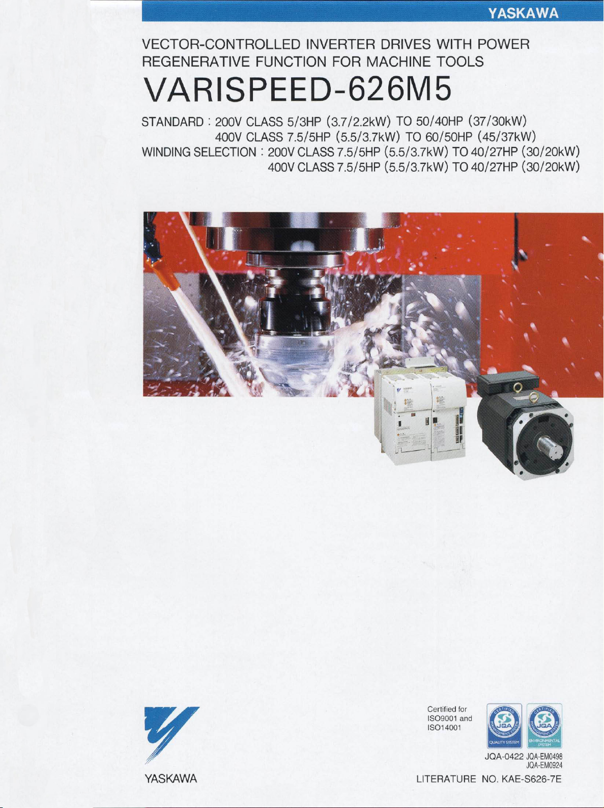
VECTOR-CONTROLLED
REGENERATIVE
FUNCTION
INVERTER
FOR
MACHINE
DRIVES
WITH
TOOLS
VARISPEED-626M5
STANDARD
WINDING
SELECTION
:
200V
400V
CLASS
CLASS
:
200V
400V
5/3HP
7.5/5HP
(3.7/2.2kW)
CLASS
CLASS
,1
TO
(5.5/3.7kW)
7.5/5HP
7.5/5HP
(5.5/3.7kW)
(5.5/3.7kW)
i!
50/40HP
TO
60/50HP
TO40/27HP
TO40/27HP
POWER
(37/30kW)
(45/37kW)
(30/20kW)
(30/20kW)
vt
j
"V
*
i
m
\«
i
[•1
1
6
V
YASKAWA
Certified
ISO9001
ISO14001
LITERATURE
for
and
no
JQA-0422
NO.
JQA-EM0498
JQA-EM0924
KAE-S626-7E
Page 2
Q
LU
LU
Q_
C/)
DC
<
>
K
P
-H|
!V
r'jt
LUTE
ijli
ui
..v
t
•T*
iRjfi
yAn&PBBD-zziMz
r
1/
'"Ns,
fj
>
•>.
r
vvsv
f
A*f%s
*
<Mh
1-,n
iflfr'~iiifn
;
ct
unit
ed£
Iring
jvj
,
f~
«ÿ***
V<
v
s
fi
mm
basi
itu*
Jrur
igh
Performance
ijuuJii/
?s*
pi’Oifa&s'dyir/
uusJ
1
4
-j
ii/J.
air/-,
T
:
t»
:-*.
t
:
j
,22,3a
;
r
:-.
i
Jujlt
r
»
>1>
TJT
i
ki
:hi)
kjf
cet
1
:
/
erfi,
r-
:-
JJJUIUJJJ
d
JJJ
rl
:
ne<j
its
?£
:
:-;
iUJl
-
:
rj
!
ifJjTii
JT
r
i
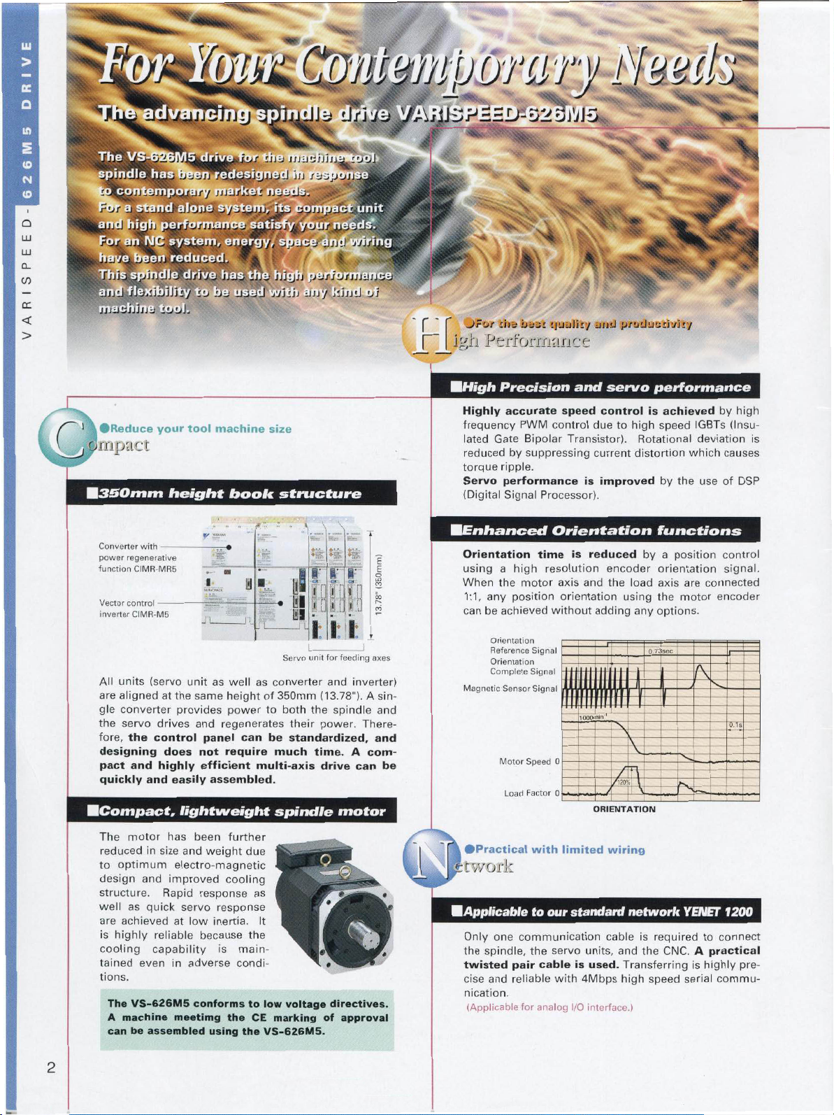
Reduce
•
impact
M3SOmm
Converter
power
regenerative
function
Vector
control
inverter
All
units
aligned
are
gle
converter
the
servo
fore,
the
designing
pact
quickly
MCompact
your
-
with
CIMR-MR5
—
CIMR-M5
(servo
drives
control
and
highly
and
tool
height
unitaswell
the
at
provides
does
easily
,
lightweight
machine
S?
H
S
JL
same
and
regenerates
panel
require
not
efficient
assembled.
book
height
power
can
size
fT
Id
#8
i
as
of
to
be
multi-axis
structure
“
\
rrr
J
lil
L
Servo
converter
350mm
both
their
standardized,
much
spindle
\
<v
I
ID
Mm
'
i
II
unit
(13.78").
the
power.
time.
drive
\
OBI]
feeding
for
and
spindle
motor
m
,
J
inverter)
There¬
A
can
E
i
in
c
D
S3
axes
A
sin¬
and
and
com¬
be
Precision
Highly
frequency
Gate
lated
reduced
torque
Servo
(Digital
n
ha
ME
Orientation
usingahigh
When
the
any
1:1,
can
be
Orientation
Reference
Orientation
Complete
Magnetic
Motor
accurate
PWM
Bipolar
by
suppressing
ripple.
performance
Processor).
Signal
need
time
resolution
motor
position
achieved
Signal
Signal
Signal
Sensor
Speed
Load
Factor
and
servo
speed
control
control
due
Transistor).
current
improved
is
Orientation
is
reduced
axis
orientation
without
0
0
encoder
and
adding
IQOOmin
SS-
ORIENTATION
to
the
performance
is
high
Rotational
distortion
by
load
using
any
0.73sec
achieved
speed
IGBTs
deviation
which
by
the
use
functions
position
a
orientation
axis
are
the
motor
options.
K
by
high
(Insu¬
causes
of
DSP
control
signal.
connected
encoder
ss:
is
The
reduced
optimum
to
design
structure.
well
are
achieved
highly
is
cooling
tained
tions.
The
machine
A
can
motor
in
size
and
Rapid
as
quick
reliable
capability
even
VS-626M5
be
assembled
has
been
further
weight
and
electro-magnetic
response
response
low
inertia.
because
adverse
conforms
using
cooling
is
the
improved
servo
at
in
meetimg
due
as
It
the
main¬
condi¬
to
CE
the
voltage
low
marking
VS-626M5.
£,
directives.
approval
of
M
twork
MApplicable
Only
one
spindle,
the
twisted
cise
nication.
(Applicable
and
pair
reliable
limited
with
our
standard
to
communication
the
cableisused.
for
analog
servo
with
units,
4Mbps
I/O
interface.)
wiring
network
cable
and
Transferring
high
required
is
the
speed
CNC.
YENET
to
A
practical
highly
is
serial
1200
connect
pre¬
commu¬
2
Page 3
VARISPEED
626M5
DRIVE
A
P
[-'
|!'-.:ible
*:
*:
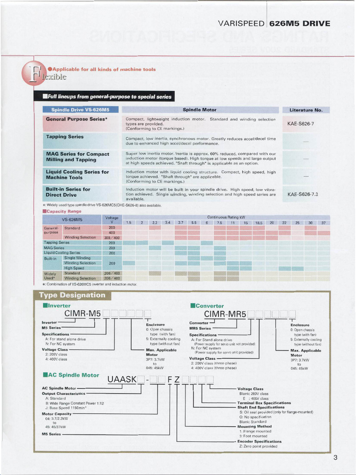
•Applicable
lineups
Spindle
General
Tapping
MAG
Series
Milling
Liquid
Cooling
Machine
Built-in
Direct
Drive
Widely
used
VS-626M5
General-
purpose
Tapping
Series
MAG
Series
Liquid
Cooling
Built-in
Widely
Used*
Combination
Drive
Purpose
Series
and
Tools
Series
type
Range
Standard
Winding
Series
Single
Winding
Speed
High
Standard
Winding
of
VS-626MC5
all
for
general-purpose
from
VS-626M5
Series*
for
Compact
Tapping
Series
for
spindle
drive
Selection
Winding
Selection
Selection
inverter
kindsofmachine
to
Compact,
types
(Conforming
Compact,
duetoenhanced
Super
induction
high
at
V
200
400
200
200
200
200
induction
Induction
torque
(Conforming
Induction
tion
achieved.
available.
1.5
motor.
for
VS-626MC5(CHE-S626-8)
Voltage
200/400
200/400
200/400
and
tools
special
lightweight
provided.
are
low
low
inertia
motor
speeds
motor
achieved.
motor
also
available.
2
series
CE
to
inertia,
high
(torque
achieved.
with
CE
to
will
Single
2.2
markings.)
synchronous
accel/decel
motor.
liquid
"Shaft
markings.)
be
winding,
3.4
induction
Inertia
based).
"Shaft
through"
built
3.7
Spindle
motor.
performance.
is
High
through"
cooling
your
in
winding
5.5
motor.
approx.
structure.
are
Motor
Standard
Greatly
60%
torque
applicable
is
applicable.
spindle
selection
Continuous
6
reduced,
low
at
drive.
7.5
and
reduces
speeds
Compact,
High
and
Rating
11
winding
compared
as
an
high
kW
accel/decel
large
and
option.
high
speed,
speed,
speed
15
selection
with
output
low
series
18.5
time
our
high
vibra¬
are
20
Literature
KAE-S626-7
KAE-S626-7.3
25
22
No.
30
37
Type
Inverter
M5
Series
Specifications
For
A:
N:
For
Voltage
200V
2:
4:
400V
AC
Spindle
Output
A:
Standard
Wide
B:
J:
Base
Motor
04:
3.7/2.
to
45:
45/37kW
M5
Series
Designation
CIMR-M5
J
—
-
stand
alone
system
2kW
-
Motor
-
Constant
1150min
-
drive
Motor
NC
Class
class
class
Spindle
Characteristics
Range
Speed
Capacity
-
Power
1
UAASK
1:12
T
Enclosure
0:
Open
type
Externally
5:
type
Max.
Applicable
Motor
3P7:
3.7kW
to
45kW
045:
chassis
(with
(without
fan)
cooling
fan)
FZ
CIMR-MR5
Converter
Series
MR5
Specifications
Voltage
A:
N:
2:
4:
For
(Power
For
(Power
200V
400V
Stand
supply
NC
supply
Class
class
class
-
system
-
-
alone
drive
for
servo
unit
for
servo
(three-phase)
(three-phase)
not
unit
Terminal
Shaft
Mounting
provided)
provided)
Voltage
Blank:
E
S:
Oil
No
0:
Blank:
Flange
1:
3:
Foot
Encoder
Zero
Z:
Class
200V
class
400V
:
class
Box
Specifications
End
seal
provided
specification
Standard
Method
mounted
mounted
Specifications
point
provided
Specifications
(only
Enclosure
0:
Open
type
5:
Externally
type
Max.
Motor
3P7:
3.7kW
to
45kW
045:
flange-mounted)
for
chassis
(with
fan)
cooling
(without
Applicable
fan)
3
Page 4
I
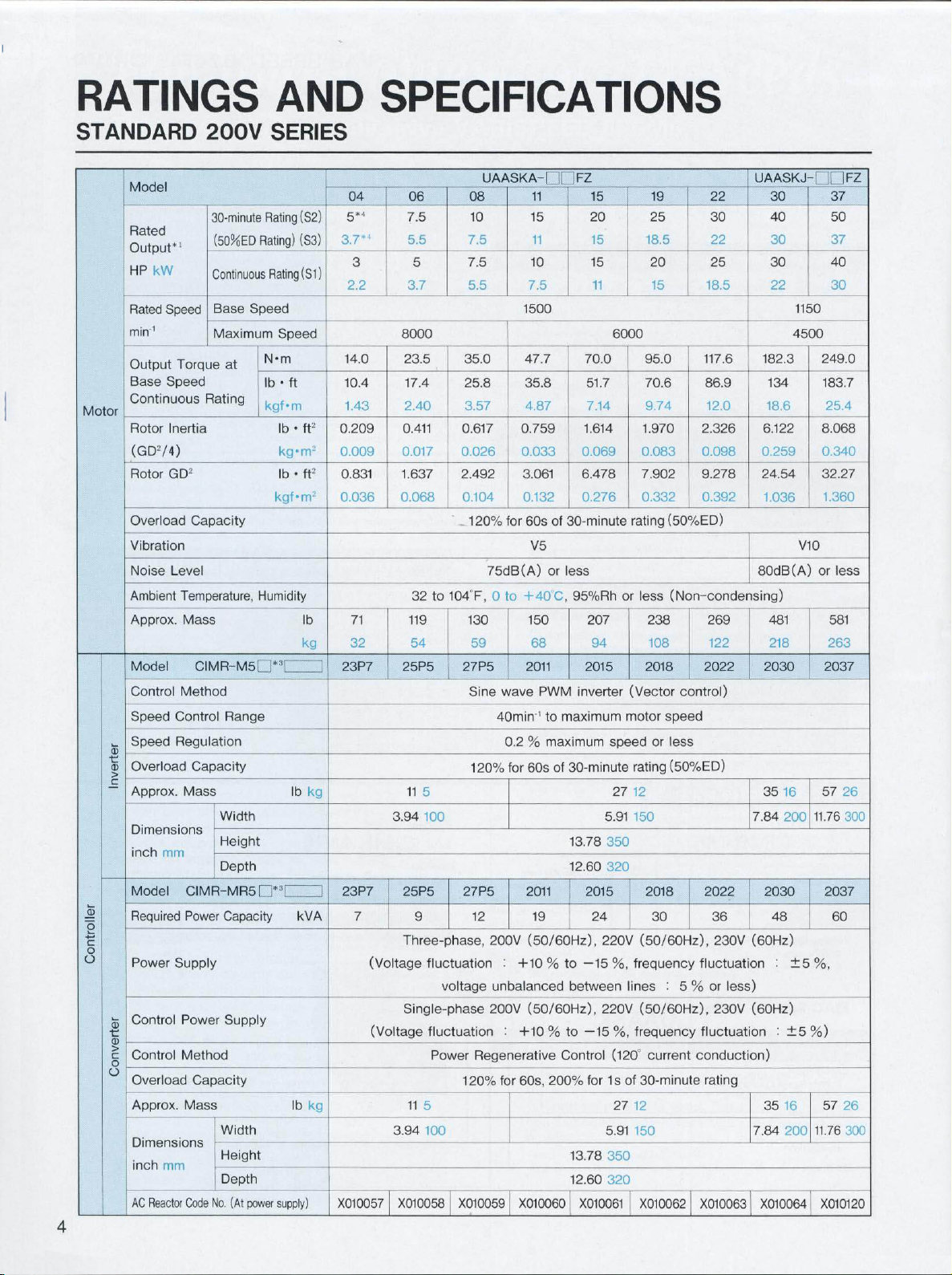
RATINGS
STANDARD
Model
Rated
Output*
HP
Rated
mirv'
Output
Base
Continuous
Motor
Rotor
(GD74)
Rotor
Overload
Vibration
Noise
Ambient
Approx.
Model
Control
Speed
Speed
%
Overload
>
Approx.
Dimensions
inch
Model
Required
2
o
a
Power
Control
s
>
Control
o
o
Overload
Approx.
Dimensions
inch
Reactor
AC
4
kW
200V
30-minute
(50/-6ED
1
Continuous
Base
Speed
Maximum
Torque
Speed
Rating
Inertia
GD2
Capacity
Level
Temperature,
Mass
CIMR-M5D*T
Method
Control
Regulation
Capacity
Mass
Width
CIMR-MR5
Power
Supply
Power
Method
Capacity
Mass
No.
Code
Height
Depth
Width
Height
Depth
mm
mm
Range
Capacity
Supply
at
(At
Speed
power
AND
SERIES
(S2)
Rating
(S3)
Rating)
(S1)
Rating
Speed
N*m
•
lb
ft
kgf*m
•
lb
ft2
kg-m2
•
lb
ft2
kgf*m2
Humidity
lb
kg
kg
lb
i*3l
1
kVA
lb
supply)
I
kg
SPECIFICATIONS
FZ
11
15
11
10
7.5
of
30-minute
V5
or
less
95%Rh
68
PWM
inverter
maximum
to
’
maximum
%
30-minute
of
60s
13.78
12.60
19
(50/60Hz),
to
%
between
to
%
Control
200%
13.78
12.60
X010061
15
20
15
15
11
6000
70.0
51.7
7.14
1.614
0.069
6.478
0.276
207
94
2015
speed
27
5.91
350
320
2015
24
220V
%,
—15
220V
%,
—15
(120"
for1sof
5.91
350
320
0.083
7.902
0.332
rating
or
less
(Vector
motor
rating
12
(50/60Hz),
frequency
lines
(50/60Hz),
frequency
30-minute
27
12
150
X010062
19
25
18.5
20
15
95.0
70.6
9.74
1.970
(50%ED)
(Non-condensing)
238
108
2018
speed
or
less
(50%ED)
2018
30
:
current
04
5“
3.7“
3
2.2
14.0
10.4
1.43
0.209
0.009
0.831
0.036
71
32
23P7
23P7
7
(Voltage
(Voltage
X010057
06
7.5
5.5
5
3.7
8000
23.5
17.4
2.40
0.411
0.017
1.637
0.068
32
119
54
25P5 27P5
11
3.94
25P5
Three-phase,
9
to
5
0.617
0.026
2.492
0.104
104F,0
fluctuation
voltage
Single-phase
fluctuation
Power
120%
11
5
3.94
X010058
X010059
UAASKA-
08
10
7.5
7.5
5.5
35.0
25.8
3.57
0.759
0.033
120%
for
75dB(A)
to
130
59
Sine
wave
40min
0.2
for
120%
27P5
12
200V
:
+10
unbalanced
200V
:
+10
Regenerative
60s,
for
X010060
1500
47.7
35.8
4.87
3.061
0.132
60s
+40C,
150
2011
2011
(50/60Hz),
22
30
22
25
18.5
117.6
86.9
12.0
2.326
0.098
9.278
0.392
269
122
2022
control)
2022
36
230V
fluctuation
or
5
%
230V
fluctuation
conduction)
rating
X010063
less)
AASKJ-
U
30
40
30
30
22
182.3
134
18.6
6.122
0.259
24.54
1.036
80dB(A)
481
218
2030
35
16
7.84
2030
48
(60Hz)
:
(60Hz)
:±5%)
35
16
7.84
X010064
1150
4500
V10
±5%,
200
FZ
37
50
37
40
30
249.0
183.7
25.4
8.068
0.340
32.27
1.360
or
less
581
263
2037
57
26
300
11.76
2037
60
57
11.76
X010120
Page 5
§
E
2
E
o
Rated
*1
:
If
*2:
Temperature
A
*3:
1
*4:
5-minute
Ambient
Storage
Humidity
Location
Vibration
output
the
input
:
For
stand
Temperature
Temperature*2
power
during
alone
is
is
lower
shipping
drive,
(50%ED)
voltage
rating
guaranteed
than
(Short
For
N
:
when
200V,
NC
the
then
period)
system
input
the
Indoor
voltage
rated
(Free
output
32
heatsink
from
1G
at10to
three-phase,
is
power
to
is
131°F,
inlet
90%RH
0
temperature
-4
to
corrosive
less
200V
not
guaranteed.
55"C
to
+
30
-20
140F,
(Non-condensing)
or
less
gases
and
than
20Hz,
50/60Hz,
at
(Non-condensing),
F,
113
to
to
dust),
0.2G
220V
60
+
at
at
0
to
+
C
altitude
1000m
20to50Hz
50/60Hz,
45°C
230V
or
or
less
60Hz.
at
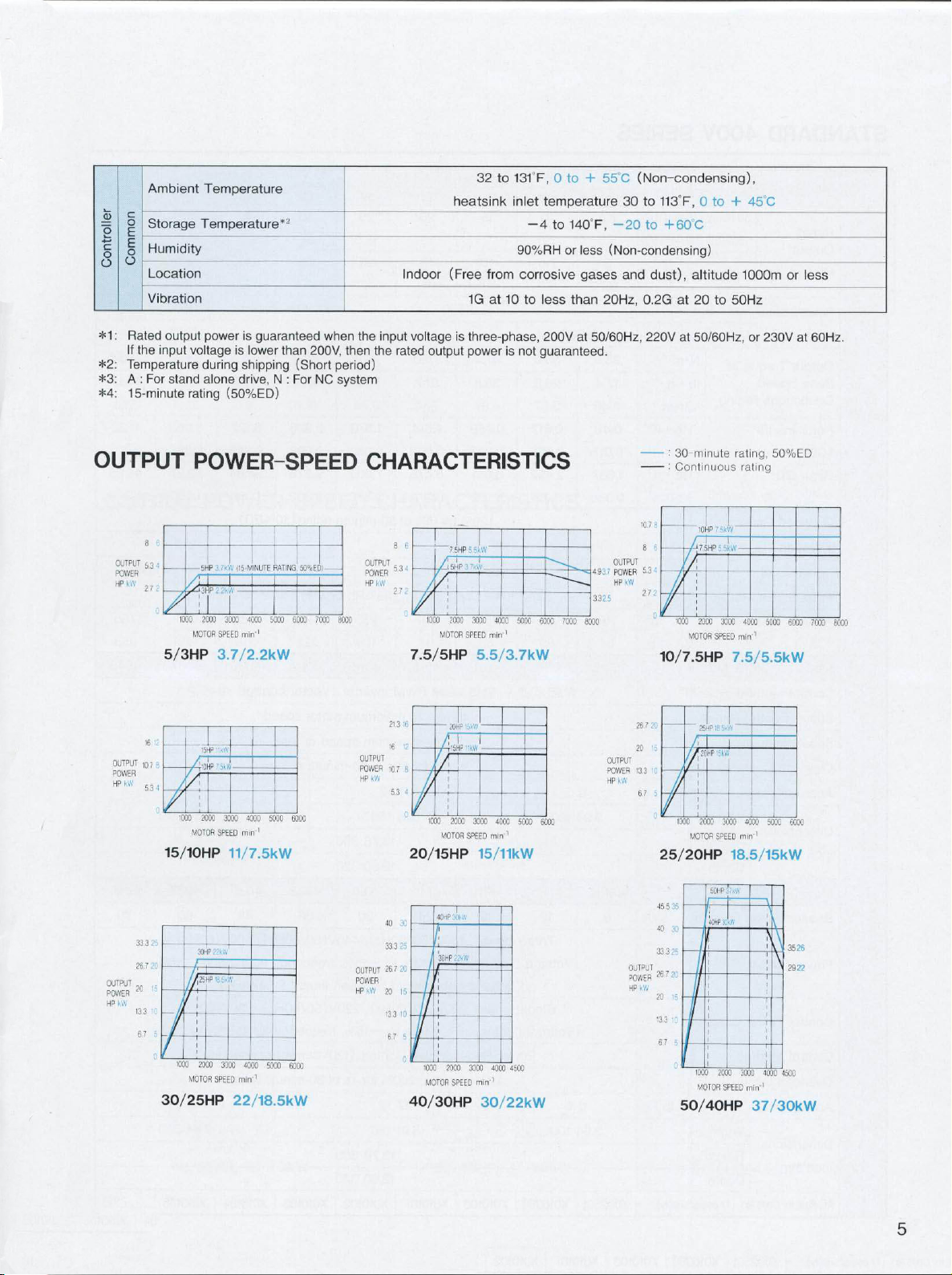
OUTPUT
8
OUTPUT
5.34
POWER
HP
kW
j
j
2
7":
5/3HP
•;
16
OUTPUT
to.7
POWER
kW
HP
4
5.3
15/10HP
25
33.3
26.7
OUTPUT
POWER
HP
KW
5
.'
i
5
67
1030
30/25HP
POWER-SPEED
-
1
50%ED|
IM'T
4000
min'1
4030
min
4000
min
'
5kW
1
RATI
5000
5030
5300
NG,
6000
6000
6000
7CCC
5HP
30CC
1000
2000
MOTOR
SPEED
3.7/2.2kW
15HP
-V’
-T4‘CHP
VH
/
1
2000
'C00
3030
MOTOR
SPEED
11/7.
3QHP
.
.
•
1
2300
3000
MOTOR
SPEED
22/18.5kW
;i5-N
CHARACTERISTICS
OUTPUT
POWER
HP
80CC
OUTPUT
POWER
kW
HP
OUTPUT
POWER
HP
KW
__
8
kW
-
3
21.3:6
16
107
5.3
40
33.3
267
20
133
67
6
J
7.5/5HP
12
6
4
20/15HP
30
25
20
15
10
40/30HP
10(10
MOTOR
'
1000
4CHP.
30rP.
r
1000
MOTOR
7
5HP
20CC
20HP
2CCC
MOTOR
T“
ktt
2300
SPEED
vi-W
--A.
300C
SPEED
7
SPEED
3000
.
40CG
5000
min'’
5.5/3.7kW
3000
4CO:
5000
min'1
15/11kW
4000
450C
min'1
30/22kW
6000
6000
7000
8000
4.93
3.325
OUTPUT
7
POWER
«W
HP
OUTPUT
POWER
HP
kW
OUTPUT
ROWER
HP
-
•
:
-
10.7
8
8
6
5.3
272
10/7.5HP
26.7
2C
20
'5
533
6.7
5
25/20HP
5
45
40
;
33.3
26.7
kW
20
133
67
30
minute
Continuous
[75HP
10CX)
200C
MOTOR
SPEED
If
25HP
1
-
20HP
1300
2CC0
MOTOR
SPEED
S0HP
36
W.
53
20
15
•:
i
0
1000
MOTOR
50/40HP
rating,
50%ED
rating
.
3000
40CC
SOOC
min'1
7.5/5.5kW
3000
4000
5CCC1
mirr1
18.5/15kW
\
2000
3000
4000
SPEED
min'1
37/30kW
\
H,,
3526
292
4500
6003
7000
8000
2
5
Page 6
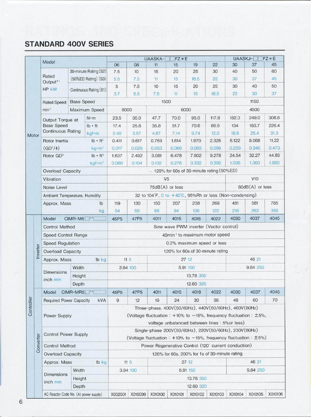
STANDARD
400V
SERIES
Motor
2
4-*
o
o
Model
Rated
Output'
HP
Rated
min''
Output
Base
Continuous
Rotor
(GD2/4)
Rotor
Overload
Vibration
Noise
Ambient
Approx.
Model
Control
Speed
Speed
G
%
Overload
>
Approx.
Dimensions
inch
Model
Required
Power
Control
G
%
>
Control
o
Overload
Approx.
Dimensions
inch
AC
1
kW
Speed
Torque
Speed
Inertia
GD2
Level
Temperature,
Mass
Method
Control
Regulation
Mass
mm
CIMR-MR5
Power
Supply
Power
Method
Mass
mm
Code
Reactor
30-minute
(50%ED
Continuous
Speed
Base
Maximum
at
Rating
Capacity
CIMR-M5D*'[
Range
Capacity
Width
Height
Depth
Capacity
Supply
Capacity
Width
Height
Depth
(At
power
No.
Rating
Rating)
Rating
Speed
N-m
•
lb
ft
kgf-m
•
lb
kg-m2
•
lb
kgf-m2
Humidity
lb
[H*3i
lb
supply)
(S2)
(S3)
(S1
ft2
ft2
lb
kg
kg
kVA
kg
)
23.5
0.411
0.017
1.637
0.068
]
45P5
I
45P5
X002501
06
7.5
5.5
5
3.7
17.4
2.40
119
54
9
8000
11
3.94
11
3.94
08
10
7.5
7.5
5.5
35.0
25.8
3.57
0.617
0.026
2.492
0.104
32
130
59
47P5
5
100
47P5
12
Three-phase,
(Voltage
Single-phase
(Voltage
5
100
X010099
UAASKA-
47.7
35.8
4.87
0.759
0.033
3.061
0.132
75dB(A)
to
104“F,
fluctuation
voltage
fluctuation
Power
120%
X010100
][
11
15
11
10
7.5
1500
1.614
0.069
6.478
0.276
for
120%
V5
or
0
to
150
68
4011
wave
Sine
40min''
0.2%
20%
1
4011
19
400V(50/60Hz),
:
unbalanced
200V(50/60Hz),
:
Regenerative
60s,
for
X010101
FZ
15
20
15
15
11
70.0
51.7
7.14
60s
less
+40C,
207
94
4015
PWM
to
maximum
for
5.91
4015
24
+10%
+10%
200%
5.91
E
*
19
25
18.5
20
15
6000
95.0
70.6
9.74
1.970
0.083
7.902
0.332
30-minute
of
95%Rh
238
108
4018
inverter
maximum
of
60s
27
12
150
13.78
12.60
4018
30
—15%,
to
between
—15%,
to
Control
for
12
27
13.78
12.60
X010102
22
30
22
25
18.5
117.6
86.9
12.0
2.326
0.098
9.278
0.392
(50%ED)
rating
(Non-condensing)
or
less
269
122
4022
(Vector
speed
motor
speed
or
less
30-minute
350
rating
320
4022
36
440V(50/60Hz),
frequency
:
lines
220V(50/60Hz),
frequency
(120
current
30-minute
of
1s
350
320
X010103
UAASKJ-I
30
40
30
30
22
182.3
134
18.6
6.122
0.259
24.54
1.036
481
218
4030
control)
4030
48
460V(60Hz)
fluctuation
less)
5%or
230V(60Hz)
fluctuation
conduction)
rating
X010104
80dB(A)
9.84
9.84
37
50
37
40
30
1150
4500
249.0
183.7
25.4
8.068
0.340
32.27
1.360
V10
or
581
263
4037
21
46
250
4037
60
:
±5%,
±5%)
:
46
21
250
X010105
FZ*E
45
60
45
50
37
306.8
226.4
31.3
11.22
0.473
44.85
1.890
less
785
355
4045
4045
70
X010106
6
Page 7

5;
§
E
2
E
o
:ÿ
:
Rated
*1
If
*2:
Temperature
A
*3:
Ambient
Storage
Humidity
Location
Vibration
output
the
input
:
For
stand
Temperature
Temperature*2
power
during
alone
is
is
lower
shipping
drive,
voltage
guaranteed
than
(Short
:
N
For
when
200V,
NC
the
then
period)
system
32
input
the
131'F,
to
Indoor
voltage
rated
0
output
+55C
to
(Free
from
1G
at10to
is
three-phase,
power
(Non-condensing),
-4
to
90%RH
corrosive
less
400V
is
not
guaranteed.
heatsink
140°F,
(Non-condensing)
or
less
gases
20Hz,
than
at
50/60Hz,
-20
or
temperature
inlet
to
+
dust),
0.2G
440V
C
60
altitude
at20to
50/60Hz,
at
30
to
113'F,
1000m
50Hz
or
460Vat60Hz.
0
to
+45’C
or
less
OUTPUT
6
8
-
OUTPUT
53ÿ
POWER
“W
HP
2J2
7.5/5HP
21
3
'
’2
16
OUTPUT
POWER
,o.7
8
KW
HP
4
5.3
20/15HP
40
25
33
3
20
26.7
OUTPUT
POWER
15
kW
20
HP
13.3
6.7
0
BOO
40/30HP
POWER-SPEED
L
.
-
7.5HP
•
;MV.
«HP
I
1000
2000
30CC
4000
5000
6000
7kW
5000
7000
6000
1000
MOTOR
'20HP
[l5HP
2000
MOTOR
SPEED
5.5/3.
'
llkV.
300C-
SPEED
min''
4000
min'1
15/11kW
40HP
/
L’Zk'.V
i3CHP
f
l
I
3000
2000
4000
W0T0H
SPEED
4500
min'1
30/22kW
CHARACTERISTICS
c
4.9
8000
3.3
OUTPUT
POWER
HP
2
5
OUTPUT
POWER
HP
107
8
,
53
W
2.7
26
20
13.3
kW
6.7
455
4C
33.3
I
„
-
2;
10/7.5HP
?0
7
-5
-
r
25/20HP
36
25
>V.
IQHP
&A
5
-/r75HP
u
n
1000
2000
3000
MOTOR
SPEED
'ÿÿÿÿ•
-?5HP
OHP'-h
w,
/n.
3000
1000
2000
MOTOR
SPEED
-.
hflHP
'
“Fn
*'A
40rtP
4000
min"'
7.5/5.5kW
h
4000
min’’
18.5/15kW
h
ffi7267
KW
HP
20
15
133
-
67
1000
2000
3000
4500
SPEED
min-’
4CC0
37/30kW
MOTOR
50/40HP
5000
5000
35
29
:
-
30-minute
:
Continuous
-
'2
16
OUTPUT
"
107
POWER
KW
HP
4
5.3
6000
7000
8000
o:
'000
MOTOR
15/10HP
25
33.3
20
26.7
OUTPUT
15
20
6000
POWER
KW
HP
13.3
/
ID
5
6.7
1000
MOTOR
30/25HP
SUP
45
60
40
53.4
45.5
40
333
02
OUTPUT
POWER
kW
HP
26
20
133
SQHP
•
(
7
-
15
1C
I
67
BOO
MOTOR
60/50HP
15HP
hjiip
2000
vHP
25HP
laxT
T
2000
SPEED
rating,
rating
"
3000
4000
min''
SPEED
11/7.
3000
4000
min''
SPEED
22/18.
\
-ff
i.
3000
400C
min'’
45/37kW
a
3
5kW
5000
40
26
35
45M
50%ED
6000
5kW
«
7
Page 8
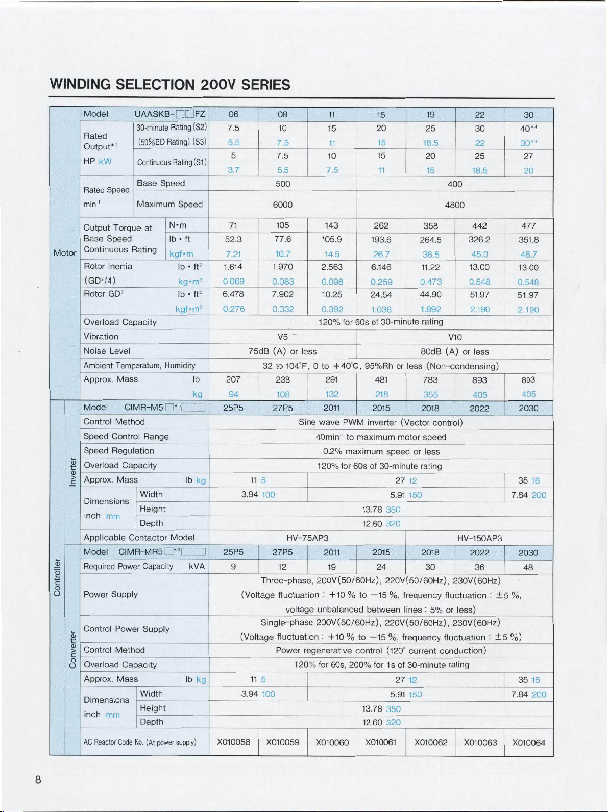
WINDING
SELECTION
200V
SERIES
Motor
2
o
o
Model
Rated
Output*
HP
Rated
min’’
Output
Base
Continuous
Rotor
(GD2/4)
Rotor
Overload
Vibration
Noise
Ambient
Approx.
Model
Control
Speed
Speed
a
Overload
s
>
Approx.
Dimensions
inch
Applicable
Model
Required
Power
Control
a>
%
Control
>
o
Overload
o
Approx.
Dimensions
inch
i
kW
Speed
Torque
Speed
Inertia
GD2
Capacity
Level
Temperature,
Mass
CIMR-M5D*3[
Method
Control
Regulation
Capacity
Mass
mm
Contactor
CIMR-MR5D*:,[
Power
Supply
Power
Method
Capacity
Mass
mm
UAASKB-DDFZ
(S2)
Speed
at
Humidity
Range
Capacity
Supply
Rating
Rating)
Rating
Speed
Nvn
•
lb
ft
kgf*m
•
lb
kg-m2
•
lb
kgf-m2
lb
Model
kVA
lb
(S3)
(S1)
ft2
ft2
lb
kg
kg
kg
30-minute
(50%ED
Continuous
Base
Maximum
Rating
Width
Height
Depth
Width
Height
Depth
06
7.5
5.5
5
3.7
71
52.3
7.21
1.614
0.069
6.478
0.276
207
94
25P5
25P5
9
75dB
32
11
5
3.94
Three-phase,
(Voltage
Single-phase
(Voltage
11
5
3.94
08
10
7.5
7.5
5.5
500
6000
105
77.6
10.7
1.970
0.083
7.902
0.332
V5
(A)
or
104
to
238
108
27P5
HV-75AP3
27P5
12
fluctuation
voltage
fluctuation
Power
1
11
15
11
10
7.5
143
105.9
14.5
2.563
0.098
10.25
0.392
120%
less
to
0
F,
+40”C,
291
132
2011
wave
Sine
40min'’
0.2%
120%
2011
19
200V(50/60Hz),
:
+10
unbalanced
200V(50/60Hz),
:
+10
regenerative
for
60s,
20%
60s
for
95%Rh
PWM
inverter
maximum
to
maximum
for
60s
13.78
12.60
to
%
between
to
%
control
200%
13.78
12.60
15
20
15
15
11
262
193.6
26.7
6.146
0.259
24.54
1.036
30-minute
of
or
less
481
218
2015
(Vector
motor
speed
of
30-minute
27
12
5.91
150
350
320
2015
24
220V(50/60Hz),
—15
frequency
%,
lines
220V(50/60Hz),
%,
for
(120°
1
s
of
27
5.91
350
320
frequency
current
30-minute
12
—15
19
25
18.5
20
15
400
4800
358
264.5
36.5
11.22
0.473
44.90
1.892
rating
V10
(A)
80dB
(Non-condensing)
783
355
2018
control)
speed
or
less
rating
HV-150AP3
2018
30
230V(60Hz)
fluctuation
:
5%
or
fluctuation
less)
230V(60Hz)
conduction)
rating
150
326.2
or
22
30
22
25
18.5
442
45.0
13.00
0.548
51.97
2.190
less
893
405
2022
2022
36
30
40*1
30’4
27
20
477
351.8
48.7
13.00
0.548
51.97
2.190
893
405
2030
35
16
7.84
200
2030
48
:
±5
%,
%)
:
±5
35
16
7.84
200
(At
Reactor
AC
Code
No.
power
supply)
X010058
X010059
X010060
X010061
X010062
X010063
X010064
8
Page 9
c
5
O
1
E
ts
E
c
o
O
O
a
Rated
*1
:
If
*2:
Temperature
*3:
*4:
20-minute
Ambient
Storage
Humidity
Location
Vibration
the
For
:
A
output
input
stand
voltage
rating
Temperature
Temperature*2
power
is
guaranteed
is
lower
during
shipping
drive,
alone
N
(50%ED)
than
:
For
400V,
(Short
NC
when
period)
system
then
the
32
input
the
131“
to
Indoor
voltage
rated
0
F,
output
to
+55'C
(Free
from
1G
at
three-phase,
is
power
(Non-condensing),
-4
90%RH
corrosive
to
less
10
200V
is
not
guaranteed.
to
140F,-20
or
less
gases
than
at
heatsink
(Non-condensing)
20Hz,
50/60Hz,
or
inlet
to
dust),
0.2G
220V
H-60C
temperature
altitude
at
20to50Hz
at
50/60Hz,
30
to
1000m
or
113“F,
or
230V
0
less
at
to
60Hz.
+45"C
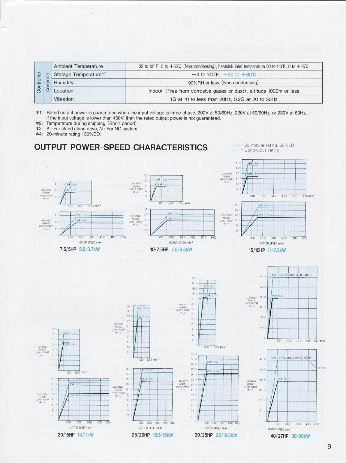
OUTPUT
i
—
SPEED
LOW
5.3
—p~
WINOING
OUTPUT
POWER
i
W
HP
fr
8
6
»'<3H
SEED
5:
WINDING
POWER
OUTPUT
HP
-ÿ4
7.5/5HP
213
187
[20HP
•
16
•33
107
53
27
16
21.3
4
187
16
.
133
3
107
8
4
53
27
20/15HP
-15HP
SPEED
LOW
WINOING
POWER
OUTPUT
HP
HIGHSPEED
WINDING
PO.VER
OUTPUT
HP
POWER-SPEED
,-MV
75HP
-
I
min
1000
•000
1-VA
ITV.
1000
2CH3
15HP
-
1000
MOTOR
3000
200C
-
75HP
3000
2000
MOTOR
SPEED
5.5/3.7kW
—
-
1
mm
200C
•
A
300C
200C
min
SPEED
’
15/11kW
min
40CC
4000
’
4500
5000
LOW
WINOING
OtTPL'T
if
HIGHSPEED
IMNOMG
0UPLT
HP
SPEED
POWER
•
POKIER
CHARACTERISTICS
IL
6000
A
267
T
18?
«
,33
*7
267
24
213
>6
133
107
24
6
52
27
SPEED
LOW
WINDING
POWER
OUTPUT
fW
If
HIGHSPEED
WWONG
ojmr
POWER
«W
H>
25HP
ih
20HP
57
6
6
1
53
27
1000
.1
2sHP
3
20HP
6
l
1000
MOTOR
25/20HP
133
137
113
10,7
'
'
V.
10HP
-
j-
1CC0
5
1000
10/7.5HP
min
200C
VA
-V,
3CCC1
200C
4000
min
SPEED
’
18.5/15kW
3000
2000
MV
I0HP
___
3000
2000
MOTOR
SPEED
7.5/5.5kW
.CW
SPEED
WINDING
XWT
if-
HIGH.
SPEED
WNC-NG
POWER
OUTPUT
HP
4800
POWER
min-'
4000
min
'
333
32
29.3
267
24
*2
187
16
13
K'
8
S3
2.7
313
32
24
292
.<
267
24
it
?2
|8?
16
•33
1C7
8
53
2.7
30/25HP
:t
-L
t
4
'
5000
30HP
25FP
'COO
/I25HP
100C
MOTOR
6000
1
2000
30HP
2000
SPEED
22/18.5kW
SPEED
LOW
MNCMQ
0UTAJ*
POWER
HP
HIGHSPEED
WINDING
POWER
OUTPUT
IP
rnin
•
f
V
3000
min0
-
4000
-
I6
H3
C7
8
K
113
lCr
3
5.3
2.7
480G
:
30-minute
:
Continuous
to
3
6
53
*
2
V
K
-
-
OUTPUT
MGH
OUTPUT
;'5HP
WW-
i
-llQHP
'tv.
1000
2000
-15HP
1
10HP
£
I00C
2000
MOTOR
15/10HP
40
333
7
SPEED
LOW
*
WINOING
POWER
•
/.
HP
X
33
67
40
i
333
26?
2C
SPEED
WINDING
POWER
HP
2C
133
6?
rating,
50%ED
rating
3000
4000
':r(,
3000
4000
min'1
SPEED
11/7.5kW
•
40HP
30
VW
27H»
X
it
F
I
5
IOOC
inti,
40HP
i“
27HP
’000
MOTOR
SPEED
40/27HP
500C
5000 5000
!20
MINUTE
2000
20-MINUTE
RATING.
vfJkW
3000
2000
min
’
30/20kW
5000
RATiNG.
3000
50%ED)
min'1
50%ED)
4000
40CC
4803
4800
min
.
35
9
Page 10

WINDING
SELECTION
400V
SERIES
Motor
2
4-»
o
Model
Rated
Output*
HP
Rated
min''
Output
Base
Continuous
Rotor
(GD2/4)
Rotor
Overload
Vibration
Noise
Ambient
Approx.
Model
Control
Speed
Speed
Overload
%
>
Approx.
Dimensions
inch
Applicable
Model
Required
Power
Control
a5
Control
>
o
Overload
Approx.
Dimensions
inch
U
AASKB-
I
kW
Speed
Torque
Speed
Rating
Inertia
GD2
Capacity
Level
Temperature,
Mass
CIMR-M5n*’
Method
Control
Regulation
Capacity
Mass
mm
Contactor
CIMR-MR5D*3[
Power
Supply
Power
Method
Capacity
Mass
mm
30-minute
(50%ED
Continuous
Base
Rating
Rating)
Rating
Speed
Maximum
N*m
at
lb
kgf-m
Humidity
Range
Width
Height
Depth
Model
Capacity
Supply
Width
Height
Depth
FZ*E
Speed
•
ft
•
lb
kg*m2
•
lb
kgf-m2
lb
kVA
lb
(S2)
(S3)
(S1
ft2
ft2
lb
kg
kg
kg
06
7.5
5.5
5
)
3.7
71
52.3
7.21
1.641
0.069
6.478
0.276
205
94
45P5
3.94
45P5
9
(Voltage
(Voltage
3.94
08
10
7.5
7.5
5.5
500
6000
105
77.6
10.7
1.970
0.083
7.902
0.332
V5
(A)
75dB
32
to
245
108
47P5
5
11
100
47P5
12
Three-phase,
fluctuation
Single-phase
fluctuation
Power
5
11
100
or
less
0
104
F,
Sine
40mim'
HV-75AP3
voltage
200V(50/60Hz),
regenerative
for
120%
11
15
11
10
7.5
143
105.9
14.5
2.568
0.098
10.25
0.392
120%
to
298
132
4011
wave
0.2%
120%
+
40C,
for
193.6
24.54
for
60s
95%Rh
PWM
inverter
maximum
to
maximum
of
60s
13.78
262
26.7
6.146
0.259
1.036
of
525
218
4015
12.60
4011
19
4015
400V(50/60Hz),
:
+10
to
—15
%
unbalanced
:
+10
%
between
to
—15
control
60s,
200%
for
13.78
12.60
15
20
15
15
11
18.5
358
264.5
36.5
11.22
0.473
44.90
1.892
30-minute
rating
80dB
or
less
581
355
4018
(Vector
motor
speed
speed
or
less
27
rating
12
150
30-minute
5.91
350
320
4018
24
440V(50/60Hz),
frequency
%,
lines
220V(50/60Hz),
%,
frequency
(120"
current
of
30-minute
1s
12
27
5.91
350
320
19
25
20
15
22
30
22
25
18.5
400
4800
442
326.2
45.0
13.00
0.548
51.97
2.190
V10
(A)
or
less
(Non-condensing)
893
405
4022
control)
HV-150AP3
4022
30
36
460V(60Hz)
:
:
5%
fluctuation
less)
or
230V(60Hz)
fluctuation
:
conduction)
rating
±5
±5
9.84
%,
%)
9.84
30
40.4
30*-1
27
20
525
387.2
53.6
13.00
0.548
51.97
2.190
893
405
4030
46
4030
48
46
16
21
250
10
AC
Reactor
Code
No.
(At
power
supply)
X002501
X010099
X010100
X010101
X010102
X010103
X010104
Page 11

output
voltage
during
stand
rating
Temperature
Temperature*2
power
is
guaranteed
is
lower
shipping
drive,
alone
N
(50%ED)
than
:
400V,
(Short
For
when
NC
the
then
period)
system
input
the
32
to
Indoor
voltage
rated
131‘F,
output
+55”C
0
to
(Free
1G
is
three-phase,
power
(Non-condensing),
-4
140
to
less
or
90%RH
from
corrosive
less
at10to
not
is
than
at
400V
guaranteed.
heatsink
inlet
F,
-20
to
+
(Non-condensing)
20Hz,
or
dust),
0.2G
440V
gases
50/60Hz,
temperature
C
60
altitude
at
20
to
50/60HZ,
at
113T,
30
to
1000m
50Hz
or
460Vat60Hz.
+45"C
0
to
or
less
Ambient
c
CD
Storage
o
1
E
Humidity
4=
E
c
o
o
o
Location
o
Vibration
*1
Rated
:
the
If
1
*2:
*3:
*4:
input
Temperature
For
:
A
20-minute
OUTPUT
6
6
SPEED
,w
PCW€R
534
„
8
2.72
—
‘
u'
6
LOW
OUTS-ER
HIGHSPEED
WINCING
OUTPUT
z
7.5/5HP
21.3
'f
187-4
'5
-j
'13
SPEED
LOW
107
WINCING
POWER
K>.w
WI1CING
POWER
«W
b
8
6
4
53
27
2
0
21316
18714
18
7
133
IC
7
IQ
9
6
4
53
27
2
20/15HP
OUTPLT
HtGHSPEEC
OUTPUT
75HP(okW-
/ÿ
1
1000
1000
2QHP
-15HP
1000
15HF
1000
POWER-SPEED
'
min
2000
3000
•
75HP
:kW
v,\
I
2000
30CC
4000
500C
OUTPUTPOWER
4800
6000
LOW
WINDING
HIGH
OUTPUT
MOTOR
5.5/3.7kW
|5KW—
li*
W
—
min
2000
’5kW-
"MV
2000
MOTOR
SPEED
15/11kW
SPEED
3000
min
min'1
1
4000
SPEED
H>«W
SPED
WINCING
POWER
kW
HP
CHARACTERISTICS
13310
-10HP
—
107
fi
SPEED
LOW
8
6
OUTPUT
OUTPUTPOWER
28’
2C
24
IB
?3l6
18?
14
'6
12
U3
:
107
8-
8
6
i
5.3
27
26.7
X
24
b
213
'fi
a
187
16
12
'33
10
107
0
8
6
4
53
;
27
25/20HP
WINDING
POWER
HIGHSPEED
WINDING
HP
KW
25HP,r..Wl
'23
HP
15'
1000
25Hf>
20HP
1000
MOTOR
i5H
27
2
oJ
•13
*37
£
8
’
4
53
27
2
0
10/7.5HP
t)
mm
2000
'
i-
'«VV
",
3000
2000
4000 4800
1
min
SPEED
18.5/15kW
*55kW
1000
2000
-10HP
VQBHP-
,
1000
2000
MOTOR
3000
'
1
<vV
.->ÿÿÿ
3000
SPEED
7.5/5.5kW
LCW
SPEED
WINCING
OUTPUT
SOWER
HP
.
HIGHSPEED
'WINCING
OUTPUT
kW
HP
min
min
POWER
'
4000
1
33
25
32
24
293
22
267
K
24
IE
213
IE
187
14
,g
133
«
1Q7
0
8
6
4
S3
27
2
O'
333
25
32
24
29.322
267
X
24
1i
213
>
'1
187
i
16
113
0
107
6
8
6
53
4
27
2
30/25HP
5000
30HP
'25HP
1000
30
25HP
1000
MOTOR
6000
•
SkVV
-B
mm
2000
HP
22kW
\
Wi
'8
3000
2000
SPEED
22/18.5kW
-
-
LOVSKED
WHONG
OUTPUTPOWER
HP
MV
10ft
SPEED
WINCING
POWER
OUTPUT
HF
A
’
4000
4800
1
min
30-minute
:
Continuous
-
B
,I5HP
11310
fi7
lOHP
8
6
4
13
I
17
7
;
16
133
,
1Q7
'
8
f
S3
4
w
15/10HP
LCW
SPEED
WINDING
OURT
POWER
V.
*>
-
NGH
SPEED
WWDWG
OUTPUT
POWER
HP
MV
rating,
rating
-W
1000
2000
15HP
:
10HP
/
1000
2000
MOTOR
11/7.5kW
4C
30
33
3
25
a?
20
15
133
to
;
67
4C
x
33
3
25
267
K
ij
20
ij
'33
67
5
0
50%ED
3000
-W
7
5kV.'
!
3000
min
SPEED
.
.
,\
40HR
27HP
A-v'v
I
I
I
J
1000
40HF
!
\w
27HP
20KW
1000
MOTOR
SPEED
40/27HP
4000
5000
4000
5000
’
,20-MINUTE
RATING
2000
3000
RATING.
20-MINUTE
1
2000
3000
1
min
30/20kW
6000
6000
50%EO)
4000
50%ED)
40CC
min'
4800
4800
min
'
35
26
11
Page 12

DIMENSIONS
AC
SPINDLE
MOTOR
(General-purpose
Series)
FOOT-MOUNTED
4-Z
TYPE
:
MTG
DIA.
Detail
HOLES
of
4
Shaft
f—
f—
m
JULl
QK
o
Kl
44°
M
Extension
TD
I
L
KD
a
A
4Note)
Jr'1
T
--
1
B
-
(Note)
,r°-
N-
j_F_
F
provided
7.5/5HP
and
SCREWS
)0
DEEP
XB
for
standard
5
5/3.7kW
models.
0
Note
:
Eyebolts
5/3HP
•
Only
for
Z>
-
w
motor
i—
are
3.7/2.2kW
5/3HP
w
.
N
not
3.7/2.2KW
D
i
i
3-m
SCREWS
0.394
10
s
DEEP
2-m
d
0.394
s
12
Standard
Winding
Selection
*1
*2
*3
Rated
Output
30-min
Rating
5*2
3.7
10
.;>
15
?Q
7
I
25
5
18
?!
10
30
S?
60*:1
45
7.5
5.0
10
7.5
15
20
15
25
3
18
30
40
2."
:
Dimensions
:
5/3-HP
:
60/50-HP
HP
kW
Continuous
Rating
h
5
3.7
7.5
Dÿ>
10
1
f.
15
11
20
15
25
18.5
30
403018.11
37
5_
3.7
7.5
5
i
.
10
5
7
15
11
20
i
:
25
18.5
27
2-'
of
(3.7/2.
2-kW)
(45/37-kW)
3#
1213
11.81
300
4'
10.28
261
11.14
28
'if
15.98
14.88
478
10.28
261
11.14
2S4
12.22
310.5
15.98
406
14.88
378
16.1
I""
16.1
409
the
A
l*'.o
6.14
7.72
,35
;
11,69
11.89
7.72
SB
ft
9.69
11.89
12.64
12.64
shaft
model
B
3.66
93
5.2
132
137
,
!
7.1
196
ft
207
402
196
246
302
321
321
extension
model
-U
C
3.94
100
3.94
|MU
4.41
1
ft
6.3
160
6.3
160
6
4
160
7.09
180
7.09
180
8,6
0.3
160
•'..8
loo
6.3
'-I
i
I
09
7
iso
8.86
22.4
8.86
225
8.86
225
is
15-minute
only
D
6.85
174
6.85
174
%
8.03
<
I
31
10.24
200
10.24
200
'4
ib6
%8
14.96
;s<
'
10.24
260
12.6
.
120
14.96
380
14.96
380
14.96
380
key
for
E
3.15
1
1
3.15
3.74
>
9
3.74
127
5
127
127
5.49
139.5
5.49
139.5
7.01
17s
127
5
127
127
5.49
139.5
7.01
178
7.01
178
7.01
178
and
the
F
1.97
"•f
3.5
so
2.76
70
3.5
89
3.5
so
1.13
105
5
127
5
127
7.01
78
1
,,,
3.5
89
4.13
105
as
5
127
6-12
1
55.5
6.87
174.5
6,87
174.5
keyway
rating
400V
G
H
0.35
"
0.35
¥8
0.39
10.59
269
10
0.39
10.59
|M
269
0.63
lo
13
0.63
411
16
0.63
13.43
341
16
0.63
16.02
16
407
0.64
16.02
lo7
In
19.88
0.83
•704
0.04
13.43
16
341
0.63
13.43
16
411
0.6)3
13.43
In
411
0.64
16.02
I"
407
19.88
405
°2f
19.88
505
ft
0,3
19.88
4o.>
are
/
continuous
series.
1.34
::
1.34
2.95
2,95
2,17
15
2.17
2.17
44
2.17
44
W
2795
2.17
45
2.17
4.'
2,17
217
2,95
75
2.95
7.4
based
J
i
;i
:
.1
>5
,
.>
75
rating.
KD
1.34
1.34
:
IS
If7
1.67
42.5
ft
m
2-4
o!
2.4
61
2.4
61
ft
If
IS
2
61
2.4
-.1
2.4
61
2.4
61
on
i
i
I
the
L
19.76
502
ff
23.23
frfK)
22.36
568
23.86
60..
2,28
ft?
35.49
899
?2?
22.46
508
23.86
not'.
26,.
3
nos
31.26
79
1
ft
ft
ft
standard
M
7
i
>
7.4
l:-:-
S.lili
220
11.42
700
11.42
2oo
11.42
700
%8
12.6
-.20
16.54
'If
1
1.12
2"(>
11.42
290
ft
16.54
420
16.54
120
16.54
420
I
N
4.92
l
8.11
206
,.M7
177
S3
,om
11.77
299
11.73
298
15.75
lou
01.73
425
8.78
224
‘ft
12.76
42
ft
16.73
124
is..;
16,5
18.3
In
model
1
.
R
6,1
i44i
7.64
194
8.66
220
10.59
2t.9
12.09
.107
12.72
323
13.58
345
15.28
17.28
149
17.5
1115
12.09
.4(6
ft
14.07
357.5
15.28
488
17.5
444.5
If5
ft
XB
1.77
1.77
2
7i'
2.76
7u
4.25
I
4.25
108
4.25
108
4.76
1.76
121
if
425
108
1.25
I
4.25
108
4.76
5.87
149
5.87
149
5.87
149
of
designed
In
inches
Shaft
Z
Kl
,ur
6,5
1
6f5
1..
°if
8.03
76
204
°i?
r
4
0.59
OS
»
I
4
0.59
9.84
15
250
0.59
9.84
15
27.0
0.75
12.6
lo
420
0.75
!§?
19
0.91
15,16
I
0.59
ft
15
9.84
0.59
2.4(
OS
15
0.59
SB
15
0.75
12.6
420
19
15.16
48.4
ft
15.16
ft
0.94
24
in
the
2.36
2
3.15
4.33
110
1.33
4.33
110
4.33
110
5.51
I
5.51
140
5.51
140
4.33
110
4.33
i
I
I
5.51
140
5.51
I
5.51
140
5.51
I
QK
Q
1.77
i
00
1.77
•
1
2.76
70
80
;.;>i
:
I
ft
to
3
54
'.,1
4.33
10
no
4.33
110
1.43
110
3.54
on
3.54
IX)
10
3.54
91'
to
I
I"
4.33
10
no
4.33
no
4.33
no
10
Japanese
QR
0.04
0.04
mi!
0.02
t»5
0.04
l
0.04
i
0.01
0.08
0.08
OO!
0.01
I
0.04
o
o
|
0.08
0.01
1
0.01
i
0.04
Industrial
Extension
T
S
0,28
...
1.1
0J28
28
Sn.
0.31
"i«»,
IS
paw
»
:».
....
.
s
"
60
r
oocw
48
l
S
mn
70
Standard.
8
0.35
"
0.35
o
0.35
9
059
10
0.13
11
0.43
!
°if
0.45
9
0.35
9
1
1.4!'
10
0.43
1
0.47
12
ft
0.17
12
fir
1.89
1.89
mm
*8
2.367llSw
2.™?=
‘f
1.89
2.17
2-76;??
2.76*“S»4
U
0.16
I
0.16
i2
0.22
5.5
0.22
5.5
033
I
0.2
6,
0.28
7
0.28
I
7
,
,.i
0.22
55
0.22
5,0
021
(,
0
28
7
1
0.3
.,
,
0.3
/.D
0.3
7.5
JIS
W
0.31
0.31
s
0.39
10
°i5,5
5
05
14
0.55
14
0.63
16
0.71
IS
0.71
18
0.79
20
0.55
11
0.55
i
l
0.63
16
0.71
0.79
20
<179
0.79
20
301
B1
d
0.63
16
(,S7
°-?,7
1.57
I"
1.57
lo
1.57
40
1.77
7
1
1.97
•
1.97
50
2.36
60
1.57
10
1.57
40
1.77
15
1.97
.40
no
2.36
60
ft
-1996.
mm
m
M6
M4
M5
M5
M5
M5
M5
M6
M6
M6
M5
M5
M5
M6
M6
M6
M6
Page 13

FLANGE-MOUNTED
TYPE
Standard
Winding
Selection
*1
*2
*3
y
4-Z
DIA.
Rated
30-min
Rating
1
1,1
if
7?
,fs
II
9
V
75
a
15
fS
&
s
40
30
:
Dimensions
:
5/3-HP
:
60/50-HP
ID
A
LB
(Note)
5/
_
“
:
MTG
HOLES
HP
Output
Continuous
ng
Rat
h
3J
E
15
n
2528
lf5
31,6
S
40
30
37
3lf
?7
75
ft
If
3,26
15
1
w
lf5
ft
a,
Iff
of
the
(3.7/2.2-kW)
(45/37-kW)
m
KL
L
'713
331,1
2i3?
303
shaft
model
KD
-t
A
ft
7.28
185
If?
Iff
to,:,
’I;13
W
15.75
400
‘0.43
UU3
,0.43
ft
15,75
400
17.77,
400
15.75
400
extension
model
_j
y
l
d
m
—
2
LB
3,,
1
7.09
180
1,00
Hftr
330
1.81
300
ft
ft-!”
13:l?
1
is
5-minute
only
fc
9603
9002
-00(0
for
,
..
key
LC
6.85
171
6.85
174
S8I
250
9.84
9J4
320
gg
ft
ft
lit
ft
ft
ft
"57
and
the
to
:
rating
400V
Note
LG
11,7
°if
“if?
°.63
ft
ft
ft
ft
ft
ft
ft
Of
°g
If
0.57
keyway
/
continuous
series.
:
Eyebolts
standard
LH
ll§
S3?
SSI
ss?
11.81
300
11.81
300
11.81
300
$
m
11.81
300
11.81
300
%6
77
ffl,
are
Detail
are
not
5/3HP
LL
LR
If?
w
,7
1
2.36
60
ft
|!U3
4.33
110
'IS1
If?
4.33
'ft
110
4.33
no
2ft
5.51
140
5.51
29,88
140
5.51
1ÿ
140
4.33
no
*»
4.33
no
‘fit?
4.33
21.97
110
5.51
If:'75
110
5.51
110
5.51
140
29.02
5.51
MO
basedonthe
rating.
of
Shaft
3
O
provided
3.7/2.2kWand
D
Z
0.43
Iff
0.43
Iff
38
0f
If?
ft
:,124
ft
0.59
15
w
'ft
°f
0.75
19
gg
°U?
Of*
ft1
0.59
ft
ft
ft
0.50
ft
0.75
as
19
14.96
ft
380
14.96
:se
1
'f1*’
standard
The
model
Extension
nx
for
17.32
17.32
ft
17.32
ft
W
7.5/5HP
I
1,1,3
'I5
m
as
110
440
as
as
110
model
is
not
5
KD
k3,4
l-'7
m
m
,„7
m
2.1
1
i
.'
fit
If
L„7
1.67
U',7
If
2.4
61
If
If
of
furnished
*'
D
w
S
5/3.
7k
W
models.
KL
Kl
W-
If?
6.85
171
If
8.03
204
71,1
S3!
ft
18295
gg
gg
221
131,1
,1.02
lift
ft
7,o
05,
ft,
lit
,3.0
If?
15,8
ft
,5,0
’if
designed
with
SCREWS
10
0.394
Q
2.36
60
2.36
.....
,,3
4.33
110
4.33
110
4.33
110
4.33
110
5.51
140
5.51
140
5.51
10
1
4.33
no
4.33no3.54
4.33
no
5.51
140
5.51
MO
5.51
140
5.51
140
in
the
eyebolts.
•
Only
DEEP
QK
QR
0.04
W
0.04
1.77
45
373
0.04
3.54
90
ft
3.54
0.04
...I
0.04
Iff
0.04
4.33
0,08
110
4.33
0.08
no
4.33
0.04
no
3.54
0.04
90
0.04
90
0.04
iff
4.33
0.,08
no
4.33
0.04
no
4.33
0.04
no
4.33
0.04
110
Japanese
for
motor
U
Shaft
S
i
1
126-Sra.
i,89
1.89
SHOOS
48
1.89
!!«*
48
2,z:=
2-36S
,,
2.76IIS
L89:;„..
'f
2.1?:P
2-Z«
2.7,7
i
2.Z6,=S
Industrial
5/3HP
3.7/2.2kW
w
2-m
0.394
S
Extension
T
'
°-8
028j0.16
0.31
0.35
0.35
0.35
0.39
10
0.43
,
0.43
047
0.35
0.35
~
039
H»
0.43
,U7
0.47
Standard,
SCREWS
10
DEEP
In
inches
U
W
u‘(i
n::!
0.31
0.39
055
°sf
022
0.55
5.5
0.55
0.22
0.24
0.63
6
0.28
0.71
0.28
0.71
03
0.79
„33
0.55
033
0.55
0.63
0.24
6116
|
of
°i72
n
03
079
079
9.3
B1
JIS
10
16
18
20
®
301
d
°if
0
f
ft
1.57
40
1
57
10
1.57
10
77
1
15
1.97
5II
60
1.57
Hi
1.57
40
1.77
45
'I?
If?
If?
If?
-1996.
mm
m
M6
M4
MS
M5
M5
M5
M5
M6
M6
M6
M5
M5
M5
M6
\16
M6
M6
13
Page 14

INVERTER
(VS-626M5)/
CONVERTER
(VS-656MR5)
Inverter
BB,
MS
vvi
w
Converter
D
W1
W
(Externally
x
Max.
\
4-d
X
5
Max.
4-d
/
ili
n
(t*
2.76
70
(Externally
llHlIlM
IP
2.76
70
fan-cooled
D1
fan-cooled
OTiMiiiifir
D1
_D_
f
23P7
25P5
27P5
2011
2015
2018
2022
2030
2037
45P5
47P5
4011
4015
4018
4022
4030
4037
4045
For
stand
without
23P7
25P5
27P5
2011
2015
2018
2022
2030
2037
45P5
47P5
4011
4015
4018
4022
4030
4037
4045
For
stand
fan)
:
3.94
5.91
7.87
11.81
3.94
5.91
9.84
alone
:
3.94
5.91
7.87
11.81
3.94
5.91
9.84
alone
W
100
150
200
:mn
100
150
250
fan)
W
100
150
200
300
100
150
250
H
13.78
350
13.78
350
13.78
350
13.78
13.78
350
13.78
350
13.78
350
drive,
N:
H
13.78
350
13.78
350
13.78
350 320
13.78
13.78
350
13.78
13.78
drive,
N:
D
12.6
320
12.6
320
12.6
320
12.6
12.6
320
12.6
320
12.6
320
For
D
12.6
320
12.6
320
12.6
12.6
12.6
320
12.6
320350
12.6
320
For
NC
NC
W1
2.95
75
3.94
100
5.91
150
9.84
2.95
_75_
3.94
100
7.87
200
system
W1
2.95
75
3.94
100
5.91
150
9.84
2.95
_75_
3.94
100
7.87
200
system
H1
12.99
330
12.99
330
12.99
330
12.99
12.99
330
12.99
330
12.99
330
H1
12.99
330
12.99
330
330
12.99
12.99
330
12.99
330
12.99
330
H2
0.39
1,0
0.39
10
0
ill
0.39
0.39
J0_
0.39
10
0.39
10
H2
0.39
10
0.39
10
0.39
_10_
0.39
111
0.39
ill
0.39
10
0.39
10
In
inches
Mass
In
Mass
mm
d
\15
M5
M5
M6
M5
M5
M5
inches
d
M5
M5
M5
M6
M5
M5
M5
D1
7.48
190
7.48
190
19
7
IB
190
7.48
7.48
190
7.48
190
7.48
190
D1
7.48
!
190
7.48
190
~
7.48
190
7.48
7.48
190
7.48
190
7.48
190
5.12
130
5.12
130
5.12
i
5.12
5.12
130
5.12
130
5.12
130
D2
5.12
130
5.12
130
5J2
130
5.12
5.12
130
5.12
130
5.12
13(1
lb
M
11
26.5
12
35.3
Jb_
w
57.3
11
5_
26.5
12
35.3
16
Approx.
kg
lb
11
5
26.5
12
35.3
16
57.3
11
26.5
12
35.3
16
Approx.
D2
without
type,
Air
Model
CIMR-M5;*
)
•:
Air
D2
D_
A:
*
type,
Air
Model
CIMR-MR5*
Air
D2
A:
*
14
Page 15

Inverter
a
o
©
in?,g,si
W1
w
Converter
o
0
CD
0
o
W1
VV
(Open
1
X
m!
'V
'
(Open
o
i
5
\
4
chassis
(
x
*Max.
4-d
*
x
T
d
3
9
r
70
chassis
[
Max.
70
type)
pi
type)
run
In
Model
CIMR-M5:*:
A:
*
Model
23P7
25P5
27P5
2011
2015
2018
2022
2030
2037
45
47P5
4011
4015
4018
4022
4030
4037
4045
For
P5
stand
Air
Air
D
CIMR-MR5:*f
A
Air
23P7
25P5
27P5
2011
2015
2018
2022
2030
2037
45P5
47P5
4011
4015
4018
4022
Air
D
4030
4037
4045
A:
For
stand
*
:
alone
alone
W
3.94
100
5.91
150
7.87
200
11.81
300
3.94
100
5.91
150
9.84
250
W
3.94
100
5.91
150
7.87
200
11.81
300
3.94
100
5.91
150
9.84
250
drive.
15.16
385
18.5
470
18.5
470
18.5
170
15.16
385
18.5
470
18.5
470
drive,
15.16 12.76
385
18.5
470
18.5
470
18.5
470
15.16
385
18.5
470
18.5
470
H
For
N:
H
N:
For
D
12.76
324
12.76
324
12.76
324
12.76
V
12.76
324
12.76
324
12.76
324
NC
D
324
12.76
324
12.76
324
12.76
324
12.76
324
12.76
324
12.76
324
NC
W1
2.95
75
3.94
100
5.91
150
9.84
250
2.95
75
3.94
100
7.87
200
system
W1
2.95
75
3.94
100
5.91
150
9.84
250
2.95
75
3.94
100
7.87
200
system
H1
14.57
370
17.91
455
17.91
455
17.91
14.57
370
17.91
455
17.91
455
H1
14.57
370
17.91
455
17.91
455
17.91
455
14.57
370
17.91
455
17.91
455
Approx.
H2
0.3
7.5
0.26
6.5
0.26
6.5
0.28
0.3
7.5
0.26
6.5
0.28
7
Approx.
H2
0.3
7.5
0.26
6.5
0.26
6.5
0.28!88.2
0.3
7.5
0.26
6.5
0.28
7
lb
lb
13.2
6
35.3
16
36.4
16.5
47.4
21.5
77.2
15.4
7
35.3
16
36.4
16.5
55.1
25
13.2
6
35.3
16
36.4
16.5
47.4
21.5
17.6
8
35.3
16
36.4
16.5
66.1
30
Mass
kg
In
Mass
kg
inches
inches
d
M5
M5
M5
M6
M5
M5
M6
mm
d
M5
M5
M5
M6
M5
M5
M6
i
5
S
Panel
3
I
;
i
w*
4
Cutout
w
Opening
«-c
fcb
i
I
V.
£
t
v
pas
Dust
Note
(Both
Gasket
:
for
Gasket
of
converter
Inverter
Model
CIMR-M5
C1MR-MR5*::
23P7
25P5
27P5
2011
2015
2018
2022
2030
2037
45P5
47P5
4011
4015
4018
4022
4030
4037
4045
A:
For
*
(Hatched
is
attached
and
stand
Area)
inverter
and
w
3.9
99
5.87
149
7.83
199
11.77
299
3.9
99
5.87
149
9.8
249
alone
on
mounting
Converter)
W1
W2
2.95
0.47
75
12
3.94
0.96
100
24.5
0.96
5.91
24,5
150
9.84
0.96
_
»
i-
2.95
0.47
J_2
JESL
3.94
0.96
100
24.5
7.87
0.96
200
24.5
N:
For
drive.
area
units.
W3
0.14
3.5
0.18
4.5
0.18
4.5
0.18
0.14
3.5
0.18
4.5
0.18 0.79
4.5
system
NC
W4
0.33
8.5
0.79
20
0.79
l!I
0.79
0.33
8.5
0.79
20
20
W5
0.22
5.5
0.79
20
0.79
M.
0.79
0.22
5.5
0.79
20
0.79
20
i
W6
3.5
89
5.51
140
7.48
190
11.42
3.5
89
5.51
140
9.45
240
In
inches
H
H1
H2
13.78
12.99
0.39
330
350
13.78
350
13.78
350
13.78
1
13.78
350
13.78
350
13.78
350
12.99
330
12.99
330
12.99|0
12.99
330
12.99
330
12.99
330
10
0.39
10
0.39
10
39
0.39
_
JO.
0.39
10
0.39
10
H4
H3
0.71
18
0.71
18
0.71
18
]
0.71
0.71
18
0.71
18
0.71
18
1.1
28
1.1
28
1.1
28
1.1
1.1
28
1.1
28
1.1
28
H5
11.81
300
11.81
300
11.81
300
11.81
::oo
11.81
300
11.81
300
11.81
300
H6
0.87
22
0.87
0.87
0.87
22
0.87
0.87
22
0.87
22
C
M5
M5
M5
M6
M5
MS
MS
15
Page 16

STANDARD
CONNECTION
-oo-ÿVV
M-
<fo—
Conneclion
Bus
Bar
DIAGRAM
3-phase
200
VAC
Single-phase
200VAC
MCCB:
MC
L:
Analog
Input
1
MCCB
R
OO-M—
S
*3
—
T
Molded-case
Magnetic
AC
Reactor
Sequence
Speed
Sequence
Alarm
1
MC
2MCCB
r
o~o
—
—M—
oo—
1
—
Ground
(100i2
Circuit
Contactor
Reference
Output
Output
|h
'
Not
Breaker
Input
2MC
or
L
—
1|
-
less)
Used
i
6
External
Power
<
/
E
<
P'0
VS
R/L1
S/L2
T/L3
A1/r
A2/t
©
1CN
Speed
(0
to
6
-
N/©
-656MR5
24V
Supply
Reference
10V
±
&
P/0
VS-626M5
*2
EXTCOMO
24VCOM
OVCOM
7
PLT
—
|
°
I/O
N0
Card
+
*
*
*PCO
(Note
EXTCOM
24VCOM
OVCOM
i
L
5V
QV
PA
PA
*
PB
PB
*
PC
PC
*
THSA
THSB
SS
£
PAO
PAO
PBO
PBO
PCO
SS
7
DT
D2
D3
D4
D5
D6
D7
D8
D9
D10
D11
D12
7
LM
7
U/T1
V/T2<
W/T:
2CN
4.5.6<
1.2.3'
1CN'
2)
6CN
SM
OV
OV
16|
17
18
19.
14.
15
13
14
15
16.
11
12
J
31
32
33'
19
20
21
22
23i
24
26
27
28
29
30
47
30
49
i
Ground
(10012
IE
IP
IP
8'
9
JE
7.
TEÿ
7
I
1
4c
Power
Cabl
N1
PI
P1
N1
i
5CN
Flat
Cable
Not
Digital
Operator
(Option)
*1
o'er
o'er
O'er
o'er
0ÿ0
0ÿ0
O'er
0ÿ0
o'er
o'er
O'er
)
»ÿ
X
I
Used
"V
£1CN
52CN
i
3CN
i
6CN
19,20,21
22,23
24
,
ID
U
12
12
14
ID
16
17
lfi
i
33
36
!
37
I
42
1
43
44
45
.26
27
28
22
41
30
N1
6
7
1
5
3
4
25
RDV
EMG
FWD
REV
TLH
TLL(INC)
SSC(SV)
RST
CHW
DAS
PPI
ORT
LGR
MGR
SCOM
ov
S5ÿ
7
ZSPD
AGR
SDET
TDET
TLE
ORG
ORE
CHWE
COM1
-o
FCO
FC1
FC2
FC3
FLTL
TALM
COM2
£1
2
less)
or
External
Power
3-phase
200VAC
*1
Supply
O'O
o'er
O'er
O'er
O'er
O'O
o'er
o'er
o'er
O'er
O'er
O'O
*3
24V
,1
Motor
Signal
..
3-digit
$
Pooling
Z2
i
2
3
4_
5
1
R
7
j*.
12.
10
12-bit
Reference
BCD
1
2
4
8
10
20
40
80
100
200
400
800
Speed
Analog
>
Load
otor
Fan
i
PG
Encoder
Output
Digital
BIN
2-digit
1
2
4
8
1
16
2
32
4
64
128
8
10
256
20
512
40
1024
80
2048
Meter
Output
Ratio
I
I
i
I
Meter
16
*
*2:
*3ÿ
:
1
indicates
Connection
EXTCOM
For
400V
shield
when
of
0
class,
wire
6CN
3-phase
the
and
and
-r
sequence
EXTCOM
400V
indicates
input
of
AC
is
common
1CN
used.
twisted-pair
is
internally
are
the
shielded
external
isolated.
wire
common.
Page 17

PERIPHEVAL
DEVICES
STANDARD
Molded-case
Breaker
Ground
Interrupter
Magnetic
(2MC)
Circuit
(2MCCB)
Fault
Contactor
CONNECTION
Supply
Power
VAC,
200
Single-phase
or
B
*1
ideiFr
o
mm/
:
;
EXAMPLE
Supply
Power
200VAC,
400VAC,
3-phase(200V
3-phase
*
B
Zero-phase
k
?
O
class)
class)
(400V
Molded-case
(1MCCB)
Breaker
Fault
Ground
Interrupter
Reactor
Input
Noise
Magnetic
(1MC)
Contactor
or
Circuit
or
Filter
*1
1
:
*
Install
2:
*
Grounding
a
one
the
surge
may
Install
magnetic
caution
malfunction.
converter
protect
VS-656MR5
(Converter)
P
=
suppressor
contactor
cause
AC
reactor
on
the
output
converter
A1/r
A2/t
|
's
signal
per
from
it
coil.
converter.
side
damage.
V
parallel
in
Failure
lines
of
the
AC
Reactor
R/L1
S/L2
T/L3
:
Comectiorÿuÿar
=
:
to
for
Install
P1N1
observe
control
AC
reactor
with
only
Power
the
this
to
the
to
*2
(L)
Supply
Grounding
Encoder
Cable
=ÿ
Motor
VS-626M5
(Inverter)
'
f
|
Cable
r
mW
v
S<
0
x
-y
B
Zero-phase
Reactor
1
U/T
V/T2
wn-3
I)
Z1.Z2.Z3
Motor
Power
f
;
c
Cooling
Supply
Molded-case
Circuit
Breaker
(3MCCB)
Ground
Fault
Interrupter
Fan
or
17
Page 18

AC
REACTOR
Use
an
AC
on
it
the
reactor
input
side
to
of
prevent
the
converter
converter
damage.
from
(VS-656MR5).
Connect
MCCB
o
—
o
—
M
M.
—
MC
,f
AC
i
V
W
Reactor
Y
Z
R/L1
i
S/L2
Converter
VS-656MR5
i
i
i
T/L3
i
i
L
200V
Converter
Model
CIMR-
MR5
23P7
25P5
27P5
2011
2015
2018
2022
2030
2037
A:
For
*
400V
Converter
Model
CIMRMR5:*:
45P5
47P5
4011
4015
4018
4022
4030
4037
4045
For
A:
*
U
m
*
X
:
stand
stand
V
Class
Current
A
20
30
40
60
80
90
120
160
200
alone
Class
Current
A
J
15
20
30
40
50
60
80
90
120
alone
Y
W
Z
Ol
Inductance
mH
0.53
0.35
0.265
0.18
0.13
0.12
0.09
0.07
0.05
drive,
Inductance
mH
1.42
1.06
0.7
0.53
0.42
0.36
0.26
0.24
0.18
drive,
J
-
1
o
C2
0.96
1.57
1.57
1.57
i
1.77
5
1
5
4.33
I
5.12
I
0.98
1.57
I
0.2
1.57295
0.2
0,2
1.77
5
0.2189
0.71
__
inch
mm
1.97
1.97
HI
1.97
tl
2.95
l(
2.95
65
42
2.95
45
2.95
.77
2.95
10
2.95
30
inch
mm
C2
2.95
2.95
40
.57
2.95
HI
40
I
2.95
I?.7
295
45
2,95
48
if!
Nameplate
D
no
D
7.i
F
E
2.76
5.12
130
5
2.76
3.15
5.12
80
130
6.3
(>(
I
3.15
7.09
I
HI
3.15
7.09
8(1
''I
3.
5
1
7.09
80
180
3.15
8.07
«
3.74
1
F
E
O
7ti
.
2
/n
3.35
6.3
16(1
65
3.15
7.09
60
I
80
3.15
7.09
80
160
3.15
7.09
60
60
I
8.07
3.15
60
3.74
8
9.45
4.33
_
X
u
© ©
©
0
J
K
L
0.13
0.13
12
30
II
13
0.09
(I
09
0.09
0.09
,:,3
0.09
07
0.09
.
'
I
.J
.
>.09
1.09
1.09
1.09
1.09
)
I
.
07
1.13
13
•
Y
Z
W
V
0.35
J
6
6
6
6-M:
0,35
0.35
ii
39
1
II
39
0.39
0.39
in
0.39
in
0.39
K
0.35
n
0.39
0.39
n
39
r
1
0.39
0.39
0.39
0.31
Terminals
0.28
0.28
0.28
0.28
0.28
0.28
0.28
0.28
0.28
L
0.28
0.28
0.28
0.28
0.28
0.28
0.28
0.28
0.39
M6
M6
M6
M6
M6
M6
VI
M6
M6
VI
VI
M6
M6
M6
3
M6
M6
M8
i
'•ÿJ
U
O
!
i
3
B2
1.73
1.73
1.93
2.07
r>2.5
l
1.97
1.97
B2
1
1
iU7
1
1.97
2.28
2.48
14
40
.97
id
.93
.97
.97
no
Dimenstions
C1
4.13
0.2
+
4.13
0.2
±
4.13
0.2
-
105
0_2
5.12
r
30
5
1
5.91
2:0.2
no
t.
i
5
-
I
5.9
0.2
150
t-
5.91
0.2
•
I
1511
0.89
0.2
L-C
n1r.
iv
0.89
0.2
it
r,
_
Dimenstions
C1
i
i
5.91i0.
:
VV.
°
-1
5.91
ISO
'
5.91
•
,L6
150
6.89
1
75
1
r
6,89
-
8317ÿ0.2
6-M;
Terminals
No.
X010057
XO
10058
X010059
10060
XO
XO
10061
10062
XO
10063
XO
XO
10064
X010120
system
No.
X002501
XO
10099
X010100
X010101
XO
10102
10103
XO
XO
101
04
X010105
X0101Q6
NC
system
Terminals
Fig.
Fig.
Nameplate
No.
A
A1
(Max.)
5.12
1
30
1
5.12
1
130
5.12
5.9
6.3
16(1
60
1
180
180
210
A
rin
r,.?,
3
6
IOO
7.09
160
160
;ÿ
09
|
2K!
210
I
5'
I
7.48
_
A1
'
XVY
U
2
1
7.09
1
7.09
2
7.09
2
8.27
3
8.27
3
_
No.
j-
(Max.)
1
i
1
1
7.09
1
1
1
8-27
1
9.15
1
B1
B
(Max.)
:uii
2.26
in
i
3.46
2.36
6(1
3.86
2.56
65
13
2.95
4.
I"
3.35
3.94
in
65
I
I
3.54
3.94
90
Kill
3.74
3.94
OO
1
3.94
H.27
1
ill
•10
1
9.06
if.!
•30
B1
B
(Max.)
.97
3
54
1
3.74
1
13
3.94
3.35
in
i
3.35
3.94
100
3.35
3.94
1
i
"
3
3.94
54
1)0
1
91
4,57
4.33
10
I
4.72
A1
_
W
Z
i—
Code
N:
For
NC
Code
For
N:
6-M:
1
u
M
M4
M5
M6
M6
6
.VI
8
VI
M8
10
M
M10
M
4
VI
Ml
M5
M6M6
M6
M6
M6
M8
8
VI
Nameplate
Approx.
Mass
lb
kg
6.6
6.6
8.8
i
13.2
17.6
17.6
17.6
-
26.0
12
33.
Approx.
Mass
Ib
kg
8
8
11
13.2
17.6
17.6
17.6
26.5
33.1
50.7
B1
f
Heat
Loss
W
35
45
50
65
75
90
90
100
1
110
Heat
Loss
W
50
50
65
90
90
90
95
110
130
18
Details
Mounting
Hole
of
A
f~U-
t
j
1
4-
Mounting
Bolts
Figure
LJTL
u
J:
B1
1
B
.B2J
Details
Mounting
Hole
_
Q
J
£
A
L
of
J
4
—
Mounting
Bolts
Figure
:
2
i
mi
_
3
D
_
E
A
L
of
Details
Mounting
Hole
!
Figure
U
4-J
Mounting
Bolts
XX
C
B
3
Page 19

ZERO-PHASE
REACTOR
Finemet
T
200
V
Model
CIMR-
M5*:23P7
M5:*
M5
M5*201
at
M5*(201
>
M5*;201
c
M5*;2022
M5*2030
M5
MR5:*!23P7
MR5*
MR5*27P5
i
MR5*201
v
MR.
5
c
o
MR5*2018
MR5
MRS*
MR5
For
A:
*
V
400
Model
CIMR-
M5*45P5
M5:*
M
5*401
M
51*401
at
M
5*40
0)
M5*
£
M
51*4030
M
5
M5*4045
MR5*45P5
MR5*47P5
MRS
0
MRS*
>
MR5*401
C
o
MR5*4022
MR5
MRS*
MR5*4045
For
A:
*
Zero-phase
Class
Recommended
Input
25P5
27P5
*
1
5
8
2037
*
25P5
1
1
20
5
2022
*
2030
*2037
stand
alone
drive,
Class
Recommended
Input
47P5
1
5
18
4022
*4037
1
*401
401
5
8
4030
*
4037
alone
drive,
stand
Wire
2
3.5
3.5
8
14
22
22
38
50
Wire
2
2
3.5
3.5
5.5
8
14
22
22
CO
I
D-
cd
2-0.22
'
Side
N:
Side
N:
a
a
3
1
Size
Size
Reactor
I
CD
ro
5,
Dia>
mm!
Output
5.5
5.5
8
14
22
30
50
80
100
NC
For
mm"
Output
2
3.5
5.5
8
14
14
22
30
60
For
NC
JL97
3.74
3.15*0-0*
Side
system
Side
system
to
!
-L
:
0-04
V
-
Max
'
80-
Model
Finemet
Model
F6045GB
1080GB
FI
F6045GB
180GB
FI
F6045GB
180GB
FI
F6065GB
F1180GB
Finemet
Model
F6045GB
180GB
FI
F6045GB
F1180GB
F6045GB
FI
180GB
F6045GB
Reduce
/3-M4
/
Hexagon
iÿii
l
3-0.18
5
:
a
IR.
*
F6045GB
Zero-phase
Code
FIL001098
i
FIL001097
FIL001098
FIL001097
F1L001098
FIL001097
FIL001098
FIL001097
Zero-phase
Code
FII.001098
FIL001097
FIL001098
FIL001097
FIL001098
FIL001097
FIL001098
Radio
Socket
5
Dia.
No.
No.
Noise
Mass:
Reactor
Recommended
Qty.
Wiring
4
|
through
1
(Diagram
4
4
(Diagram
4
4
1
through
(Diagram
1
4
4
(Diagram
4
Reactor
Recommended
Qty.
Wiring
4
1
through
(Diagram
4
1
4
4
(Diagram
4
4
1
through
(Diagram
1
4
4
(Diagram
1.02
26
Max
0.031b
95g
1
Method
passes
core
series
passes
core
series
Method
passes
core
series
passes
core
series
(Made
Note:
A)
B)
A)
B)
A)
B)
A)
B)
by
Finemet
h
S
oj
L-
I
?
2
s
to
S
3
in
is
a
C\J
Tf
d-
V
i>-
CM
s
CD
r
2
CM
S'_
Can
inverter
Also,
Connection
Close-up
:
If
*
install
Connection
Power
Supply
It
:
*
install
is
a
*
i
2
in
m
tO
Hitachi
registered
-tH
'
7.13
±0.04
5.91
=4=t
Model
9.49
8.66*0-02
Metals,
trademark
'
:
"
Max
•
-
<30
i
Max
241
220
of
.
F1
1080GB
Max
Hitachi
.3-M5
Hexagon
‘3-0.2
.0.47
'
Ltd.)
co
°.-
-F-|—
Model
F200160PB
be
used
but
zero-phase
a
Power
Supply
of
%
zero-phase
a
the
reactor
ACL
*
only
not
alsoonthe
reactor
Diagram
ACL
*
WT2-phase
pass
st
t
,
pass
2nd
-
pass
3rd
pass
4th
is
reactor
primary
the
on
Diagram
MR5
M5
on
input
reduces
(Output)
A
MR5
P-P
R/L
1
U/T1
S/L2
V/T2t-/!|j
T/L3
W/T3
N
N
Wiring
usedonthe
AC
(Output)
B
Zero
the
side
M5
—
Pass
each
(U/T1,V/T2,W/T3)
through
input
line
Phase
4Bi|Sffe
in
reactor
wires
series
on
(U/T1,V/T2,W/T3)
winding.
without
is
used
on
primary
the
AC
the
input
line
Put
cores
a
zero-phase
the
all
reactor
Metals,
Socket
Dia.
12
I'M
co
i
CM
o
output
of
noise.
Zero
Reactor
JP
<5
wire
the
side
(ACL).
Reactor
sideofthe
(ACL).
Ltd.
Mass:
Mass:
side
the
Phase
core
(he
of
through
4
u
1.02
1
.
Max
0.091b
620g
1.65
-IF
Max
0.32lb
2260g
of
the
converter.
\
IM
times.
converter,
4
converter.
19
Page 20
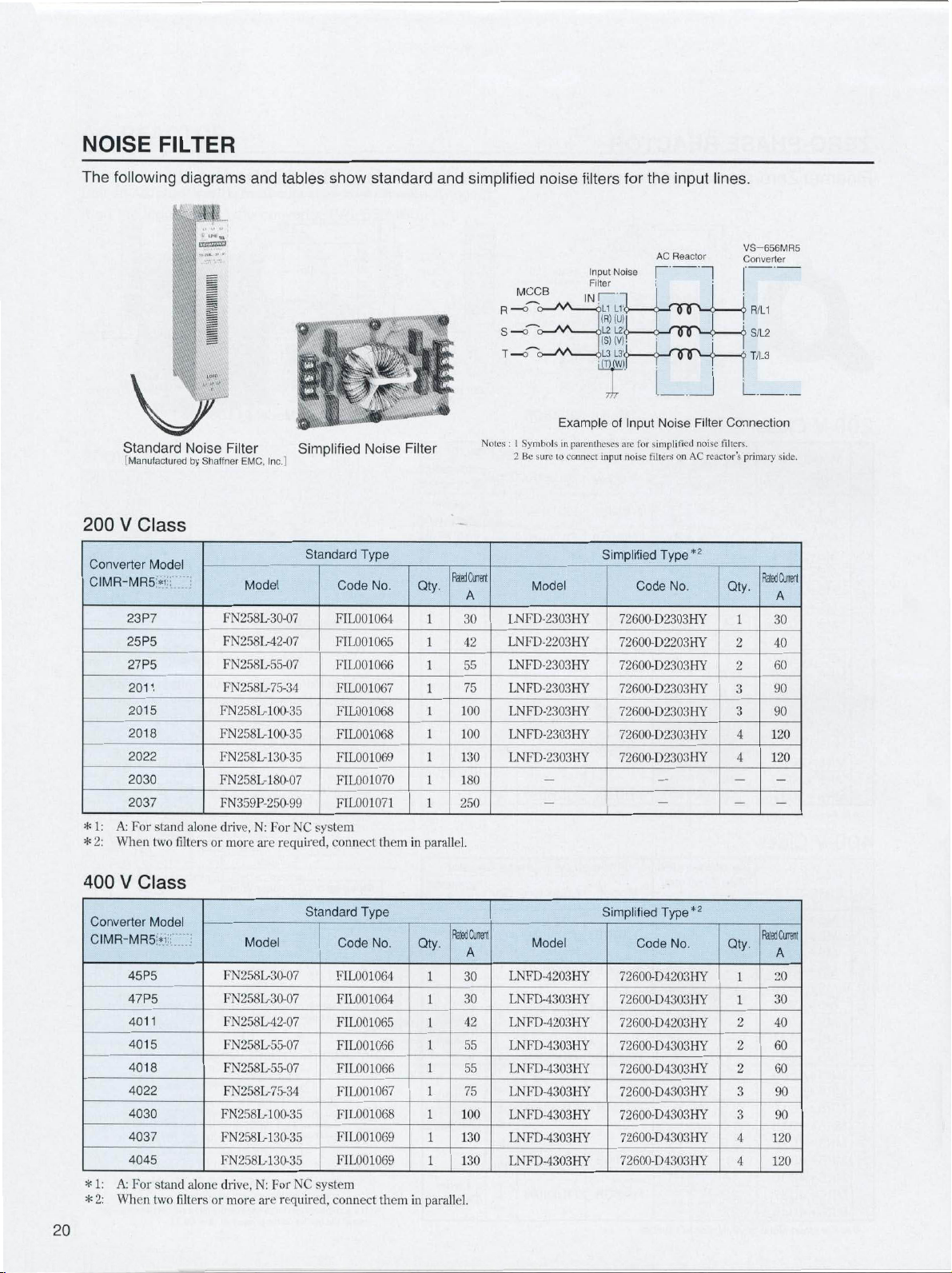
NOISE
FILTER
The
following
\
Standard
[Manufactured
200
V
Converter
CIMR-MR5
23P7
25P5
27P5
2011
2015
2018
2022
2030
2037
A:
1:
*
2:
When
*
V
V/
Class
Model
*ii;
For
stand
two
diagrams
,M
'
CEDED
wMv
Isl
Noise
by
Shaffner
alone
filters
or
and
tables
*»
*
m
IP*
»
Filter
EMC,
Model
FN258L-30-07
FN258L-42-07
FN258L-55-07
FN258L-75-34
FN258L-100-35
FN258L-100-35
FN258L-130-35
FN258L-
FN359P-250-99
drive,
more
Inc.J
180-07
N:
are
For
Simplified
NC
required,
show
W.W.W'AV
I
Standard
Code
LOO
FI
FIL001065
FIL001066
LOO
FI
FI
FIL001068
FIL001069
FIL001070
FI
system
connect
standard
?;/
V*
Si
»
Noise
Type
No.
1064
1067
1068
LOO
1071
LOO
them
Filter
Qty.
parallel.
in
1
1
1
1
1
and
simplified
RatedCurrent
A
30
42
55
75
100
1
1
100
1
130
180
1
250
MCCB
o
R—
o
S
—
T-HTO
Notes
I
:
Symbols
Be
2
Model
LNFD-2303HY
LNFD-2203HY
LNFD-2303HY
LNFD-2303HY
LNFD-2303HY
LNFD-2303HY
LNFD-2303HY
noise
filters
Input
Filter
IN
o
ExampleofInput
parentheses
in
sure
to
connect
for
the
AC
Noise
11
L1i
(R)
(U)
L2L
2
!
(S)
(V)
1
L3‘
J>L3
i(T)jW)|
7/7"
input
Simplified
1
Noise
for
are
simplified
filtersonAC
noise
Type*2
Code
72600-D2303HY
72600-D2203HY
72600-D2303HY
72600-D2303HY
72600-D2303HY
72600-D2303HY
72600-D2303HY
input
Reactor
OfTM
nnp
Filter
No.
lines.
-
j
noise
reactors
VS-656MR5
Converter
R/L1
•i
S/L2
j>
T/L3
t
i
Connection
filters.
primary
Rated
Qty.
30
1
40
2
60
2
3
90
3
90
4
120
120
4
side.
Curent
A
20
V
400
Converter
CIMR-MR5
45P5
47P5
4011
4015
4018
4022
4030
4037
4045
A:
1:
For
*
When
2:
*
Class
Model
*1
stand
two
alone
filters
or
Model
FN258L-30-07
FN258L-30-07
FN258L42-07
FN258L-55-07
FN258L55D7
FN258L-75-34
FN258L-1
FN258L-1
FN258L-
drive,
more
130-35
For
N:
are
00-35
30-35
NC
required,
Standard
Code
FIL001064
FI
FIL001065
FIL001066
FIL001066
FI
FI
FIL001069
FI
system
connect
Type
LOO
LOO
IDO
LOO
No.
1064
1067
1068
1069
them
Qty.
1
1
1
1
1
1
parallel.
in
Cjnent
Rated
A
30
30
42
55
55
75
100
130
130
Simplified
Model
LNFD-4203HY
LNFD-4303HY
LNFD-4203HY
LNFD-4303HY172600-D4303HY
LNFD-4303HY172600-D4303HY
LNFD-4303HY172600-D4303HY
LNFD-4303HY
LNFD-4303HY
LNFD-4303HY
Type*2
Code
No.
72600-D4203HY
72600-D4303HY
72600-D4203HY
72600-D4303HY
72600-D4303HY
72600-D4303HY
Qty.
1
2
2
2
3
3
4
4
Rated
Cerent
A
20
30
40
60
60
90
90
120
120
Page 21

Dimensions
Standard
•
Model
FN258L-30-07
FN258L42-07
FN258L-55-07
FN258L-75-34
FN258L
FN258M30-35
FN258L-
FN359P-250-99
100-35
180-07
Type
DWG
1
1
1
2
2
2
3
4
in
inches
A
13.19
335
12.95
329
12.95
329
12.95
329
14.92±0.06
379±1.5
17.28±0.06
439±
1.5
17.24±0.06
438±
.5
1
mm
B
±0.04
5.91
150±1
7.28±0.04
185±1
7.28±0.04
185
±1
8.66
220
8.66
220
9.45
240
9.45
240
C
2.36
60
2.76
70
3.15
80
3.15
80
±0.03
3.54
±0.8
90
±0.03
4.33
110±0.8
4.33±0.03
±0.8
110
See
D
E
12.6
12
305
320
12.36
11.81
300
314
11.81
12.36
300
314
12.36
11.81
300
314
±0.05
±1.2
±1.2
14.33
364
16.3
414
16.26
413
13.78
350
15.75±0.05
400
15.75±0.05
400±1.2
dimensionsinthe
F
1.38
35
1.77
45
2.17
55
2.17
55
2.56
65
3.15
80
3.15
80
G
0.26
6.5
0.26
6.5
0.26
6.5
0.26
6.5
0.26
6.5
0.26
6.5
0.26
6.5
drawing.
H
15.75
400
19.69
500
19.69
500
19.69
500
J
±0.
1
0.06
0.35
1
0.47
0.04±0.004
1.5
0.06
0.47
1.5
0.06
1.5
0.06
1.5
0.12
3
0.59
0.16
4
O
L
M5
9
M6
12
M6
12
M6
M10
M10
M10I50mnr
15
P
AWG10
AWG8
AWG6
-
Mass
1.8
6.2
2.8
6.8
3.1
8.8
4.0
12.1
5.5
16.5
7.5
24.3
11
35.3
16
lb
kg
4
Simplified
•
Model
LNFD-2203HY
LNFD-2303HY
LNFD-4203HY
LNFD-4303HY
a*
u.
s
—
i
E
u
C
4
1
Type
in
E
A
D
Drawing
E
A
D
Drawing
Code
No.
72600-D2203HY
72600-D2303HY
72600-D4203HY
72600-D4303HY
inches
mm
i
3
I
1
3
}
ll:::
Ei
H
p
i
a
-M-
2
O
III
Noise
3.94
100
3.94
100
4.92
4.92
Drawing
0.06
±0.06
01
1
Dia
10.0218.27
Drawing
E
A
D
ir
Filter
8.27
210
8.27
210
9.45
240
9.45
240
•
±0.02
•
I
'
2
'
4
w
Oi
\
h,
\
=t->y
si
C\i+I
3.74
95
3.74
95
4.92
125
4.92
125
::
-
B
1.69
1.69
C
“1
11“
745*±5-
1
06
;
•
0.01
8
o
5
s
i
i
0.12-f—
±0.01
DWG
W
DAH
9.45
240
9.45
240
10.63
270
10.63
270
3
5
4.92
125
4.92
125
6.1
155 125
6.1
155 125
—>
I
i
L
4*
20.311
22.2
0.35)0
9-
8.27
5
5
5
5
i
“
J
c
CO
C
1.3
33
1.3
33
43
43
2i2r
64
3.94
•
0
Terminal
X
0.35
9
0.39
10
0.35
9
0.39
10
Note:
02
8
o
S
CD
CM
\
5
0.04
=
L
T
I
I
0.2
Drawings
M5X8
8
°
z
.1.
Y
0.43
11
0.51
13
0.43
11
0.51
13
Pi
1
Mass
lb
3.3
1.5
3.5
1.6
4.9
2.2
4.9
2.2
show
kg
W
A
(Note)
noise
Detail
Terminal
Station
filters
of
n
U|
4
for
1
I
co
D
*
lo'x
three-phase
X
Detail
-17
0
2
1
Dia.
Mounting
1.18
3C
inverters.
I4
Mounting
of
C\|
OLD
0.ÿ1
g.59
To
1?
:
Screw
Drawing
C.
x8
Hole
'
4-
x10
M4
5
21
Page 22

MOLDED-CASE
CIRCUIT
BREAKER/MAGNETIC
CONTACTOR
Connect
converter
required.
MC
if
n
Molded-case
Breaker
200V
*
Class
Converter
Model
CIMR-
MR5*
23P7
25P5
27P5
2011
2015
2018
2022
2030
2037
For
stand
A:
MCCBs
between
(VS-656MR5)
|
$
§
Circuit
(MCCB)
Power
Capacity
kVA
1MCCB 1MCCB
7
9
12
19
24
30
36
48
60
drive,
alone
For
N:
main
input
M
Power
Magnetic
100
125
150
175
250
system
NC
circuit
terminals
Supply
Contactor
(MC)
Rated
30
40
50
75
!
power
R,
S
5/
MCCB
Current
2MCCB
3
3
3
3
3
3
3
3
3
and
supply
T.
3-phase
200V
A
3MCCB
and
Connect
R—
S
AC
*
T
Single-phase
200VAC
:
For
*
3
3
3
3
3
3
3
3
3
O
O
—
O
—
400V
1MCCB
o-M
o—
r
—
class,
Rated
1MC
20
30
40
60
75
100
125
150
200
AV
2MCCB
O
3-phase
1MC
AA
o
—
M
o
—
MC
Current
2MC
—
400VAC
A
2MC
3
3
3
3
3
3
3
3
3
L
is
O
•O
•o
used.
3MCCB
o-M
cÿV\
b—M
R/L1
n
S/L2
->
T/L3
A1/r
]
A2/t
R1
S1
VS-656MR5
Main
Circuit
Supply
Input
Control
Power
Supply
Input
Power
To
Motor
Cooling
Fan
22
400V
Converter
Model
CIMR-
MR5*
45P5
For
A:
*
47P5
4011
4015
4018
4022
4030
4037
4045
stand
Class
alone
Power
Capacity
kVA
1MCCB
9
12
19
24
30
36
48
60
72
drive,
N:
For
1MCCB
NC
system
20
25
40
50
60
75
100
125
150
Rated
MCCB
Current
2MCCB
3
3
3
3
3
3
3
3
3
A
3MCCB
MC
Rated
Current
1MC
2
2
2
2
2
2
2
2
2
15
20
30
40
50
60
80
100
125
A
2MC
3
3
3
3
3
3
3
3
3
Page 23

OPTION
DIGITAL
digital
With
setting
OPERATOR
operator,
monitoring
and
MAGNETIC
is
motor
of
compact
a
winding
transfer
by
an
inverter.Amechanical
or
times
more
f
4
in
8
o
O
2.56
3.35
3.82
This
for
posed
directly
million
Dimensions
MAGNETIC
can
operation,
performed.
be
remote
sar-*
SjJSJjeJ
CONTACTOR
magnetic
selection
structural
is
contactor
operation.
contacts,
assured.
1
Main
Model
mm
&
o|
5;
<ST
sill
Circuit
Terminals
HV-75AP4
16
15
ft
©
s
IS
5.71
6.3
.
(M5)
METHOD
inches
0
ob
83
*7
SENSOR
visible
FOR
developed
It
can
be
lifetime
Control
Terminals
a/
t
11
SLi
145
.60
is
5
com¬
driven
of
Circuit
(M4)
3
G1
'
j7)
12
1/
4-M6
Mounting
Holes
Item
Digital
Operator
Extension
Cable
WINDING
Type
JVOP-132
W5301
W5303
SELECTION
Model
Contact
Rated
Rated
5
Breaking
Open/close
Mechanical
Control
Mass
Ambient
Humibity
Applicable
Capacity
*
:
1-hour
Insulation
Applying
Current
Magnetic
Voltage
Current
Capacity
Frequency
Duration
Coil
Temperature
Inverter
or
more
dwell
Continuous
30minutes*
220V
440V
220V
400V
_#
Main
Terminals
ORIENTATION
Constant
monitoring,
performed.
1m
3m
Main
of
Life
Rating
lb
3.7kW
5.5kW
required
time
is
4-M6
Mounting
Holes
.
fMJi
3
S
W
$
j?
«
UD
/
Circuit
(M8)
Models
Description
setting/reference,
display
fault
Required
tor.
HV-75AP4
contact
75A
A
87
200A
150A
50/60HZ,
200V
5.5
2.5
I
10
to
to
after
Control
_
0.87
22
when
|
HV-150AP4
3NQ3NC,
:
600
5
million
220
14
131
to
%
to
RH
95
15kW|l8.5kWto30kW|
18.5kW
15kW
applying
Circuit
Terminals
6.69
170
0.87
22
*
II
1.34
34
1
34
"U*52
HV-150AP4,
7.56
34
_2.52
192
HV-200AP4
operation
run/stop
and
auxiliary
A
digital
a
]
HV-200AP4
contact
600V
150A
1
75
400A
300A
using
times/hr
times
30kW
supply
230V
37kWto45kW
for
V
50/60HZ.
11
5.0
F
(Non-condensing)
to
power
(M4)
0.87
22
:
&
1.34
34
sTf1
200A
226A
400A
300A
12.1
37kW
30
status
can
opera-
1NO
:
60Hz
5.5
minutes.
be
magnetizer
A
magnetic
and
detect
the
is
mountedonthe
sensor
position
h
»
Iff
for
on
the
constant
load
fixed
angle
I
shaft
rotor
section
positioning.
to
Position
Stop
Position
Stop
Position
Retention
Resistant
Orientation
Magnetizer
Magnetic
1:
When
*
excluding
*2:
Continuous
Displacement
Item
Detection
1
*
Accurancy
Torque*
Card
Sensor
magnetizer
a
mechanical
I
*
l
rated
becomes
position
Detects
Stops
at
Adjustable
head
Continuous
_
is
mounted
errorsorerrors
may
torque
larger
change
position
Type
Type
not
following
magnetic
Dy
magneto
facing
range
in
the
±0.2
rated
Code
:
MG-1378BS
:
MG-1444S
:
Note
Standard
:
FS-1378C
:
FS-200A
:
Standard
Note
diameter
on
120
causedbyexternal
obtained
be
rapid
Contents
using
and
±2‘by
or
less
magneto
center
control
arc
magnetic
magnetic
of
constants
sensor
flu*
of
change
torque/±O.Tdisplacement*2
:
No.
ETC
load
accordingtogain
load
variation.
6261
type
type
axis
4X
_
MG-1378BS
is
FS-1378C
is
circumference,
magnetic
setting.
field.
sensor
23
Page 24

ENCODER
METHOD
ORIENTATION
Positioning
command
one
rotation
signal
coder
performed
is
of
12-bit
into
and
L"‘
"SB
binary
4096
encoder
R;u
H57365B-MI
CONNECTOR
Required
inverterorthe
Code
72626-CA01
72626-CA02
72626-CA03
72626-CN01
72626-CN02
72626-CN03
Note
No.
1
Plugs,
connector
option
Inverter
CIMR-M5AI
Standard
M5A
ciMR-M5Anmn
M5A
With
Method
Orientation
Card
ciMR-M5Ancrr]
M5A
With
Sensor
Method
Orientation
ciMR-M5Nmnn
M5N
Standard
ciMR-M5Nnmn
M5N
With
Method
Card
CIMR-M5N[~TT~n
Sensor
Orientation
shell
M5N
Orientation
With
Method
kits
basedonthe
or
using
type
$
>
:ir
'""P
according
differs
card.
IMl
Encoder
Magnetic
Card
Encoder
Magnetic
Card
are
not
3-digit
the
BCD,
load
orientation
SUP
;
j
;
Name
MDR
MDR
MDR
MDR
MR
MDR
MR
MDR
MDR
MR
MDR
provided
stop
dividing
shaft
B
3
to
the
Connector
Number
Plug
P
36
P
20
P
50
P
36
i
201
50
P
14P
>
361
20
P
50
P
14P
P
36
P
20
36P
20P
14P
36
P
20P
14P 14P
the
for
angle
en¬
card.
36P
20
50
36
20P
50P
14P
36
20
50
14
36
20
36P
20
14P
36
20
MR
Positioning
Position
Stop
Stop
Resistant
Orientation
Load-shaft
*1:
*
*3:
of
Pins
Shell
Kit
P
P
P
P
P
P
P
P
P
8P
P
8P
P
P
8P
connector.
Item
Position*
Repetition
Position
Functional
Origin
2:
from
Continuous
Displacement
Detection
Accuracy
Torque*
Card
Encoder
can
be
the
encoder
Connector
Qty.
(each)
1
1
1
1
2
1
1
1
1
1
1
1
1
1
1
2
1
1
1
1
1
1
*
errors
obtained
rated
becomes
1CN
2CN
6CN
1CN
2CN
8CN
6CN
9CN
1CN
2CN
6CN
10CN
1CN
2CN
4CN
1CN
2CN
8CN
4CN
9CN
1CN
2CN
4CN
10CN
i
such
phase-C
torque
angle
Detects
Stops
at
according
Angular
Continuous
backlash,
as
by
setting
may
larger
No.
Contents
Absoluteorincremental
A,B
by
position
the
load
to
resolution
or
shaft
0.088
is
generating
C
by
set
externalorinternal
origin.*2
(=36074096).
±0.2°
torque/±0.1
rated
No.
Code
Type
NE-1024-2MD
eccentricity,
startup
be
obtained
(Noii-shielded)
(Non-shieided)
(Non-shielded)
(Non-shielded)
memory
at
rapid
Plug
(Solded)
Shell
kit
Plug
(Solded)
kit
Shell
Plug
(Solded)
Shell
kit
Plug
(Solded)
Shell
kit
forward
accordingtogain
load
10136-3000
1
101
1
10150-3000VE
10350-52A0-008
10114-3000VE
10314-52A0-008
MR-8LFG
pulse
not
following
2.
9.10CN
constant
Connector
1CN
(36P)
8CN
(20P)
6CN
(50P)
(14P)
4CN
(8P)
pulses
or
below
:
ETC62613X
are
etc.
the
number
to
run
load.
variation.
Model
VE
0336-52
A0-U08
20-3000
VE
0320-52
A0-008
method
shaft
of
load
command
displacement*3
excluded.
of
offset
setting.
(36P)
MDR
(36P)
MDR
(20P)
MDR
(20P)MDR
(50P)
MDR
(SOP)
MDR
(14P)
MDR
(14P)
MDR
encoder
pulses
Maker
Sumitomo
3M
Ltd.
Honda
Tsushin
kogvo
Co.,
Ltd.
24
Page 25

BUS
Bus
bars
inverter.
Choose
inverter
BAR/CABLE
and
cables
appropriate
combinations.
required
are
bars/cables
connect
to
according
converter
the
to
with
converter-
200V
Class
Converter
CIMR-MR5*
23P7
25P5
27P5
2011
2015
2018
2022
2030
2037
Note:Inverter
Combination
Model
capacity
Inverter
CIMR-M5*
23P7
25P5
27P5
2011
2015
23P7
25P5
27P5
2011
2015
2018
2022
2030
2037
23P7
25P5
27P5
2011
2015
2018
2022
2030
2037
should
not
Model
exceed
Parts
Code
72626-
72626-W100150
72626-W150100
72626-W150150
72626-W1
72626-W150300
72626-W300100
72626-
72626-W300200
72626-W300300
converter
capacity.
W1001
50200
W3001
No.
00
50
400V
Converter
CIMR-MR5*
For
stand
A:
*
Class
45P5
47P5
4011
4015
4018
4022
4030
4037
4045
Combination
Model
drive,
alone
Inverter
CIMR-M5
45P5
47P5
4011
4015
45P5
47P5
4011
4015
4018
4022
4030
4037
45P5
47P5
4011
4015
4018
4022
4030
4037
4045
NC
N:
For
Model
*
system
Parts
Code
No.
72626-W100100
72626-W100150
72626-W1501
7
2626-W1501
00
50
72626-W250250
7
2626-W2501
00
72626-W250150
2626-
7
W250250
Bus
Bar/Cable
Parts
72626-
72626-W100150
72626-W150100
72626-
7262672626-
7262672626-
72626-W250250
7262672626-
72626-
7
2626-
Specialized
Code
No.
W1
001
W1
501
W1
50200
W1
50300
W2501
W2501
W3001
W3001
W300200
W300300
Dimensions
Bus
L
00
50
00
50
00
50
Bar
Insulated
Specialized
Oi
mension
inch
Hv
6.59
167.5
5.
SI
17.5
1
7.68
195
9.65
24
3.58
1
34
5.8
7-5
4
1
7.68
95
1
1
I
295
.7
13.58
34
15.55
395
l
9
!
_
1
tube
5
5
.6
.
5
l
Flat
Cable
L
Bus
Bar
L
Qty.
2
2
2
2
2
1
2
2
2
1
:»
2
2
2
!
'
2
2
Dimension
inch
3.94
3.94
12.99
1
3.94
9.06
12.99
Flat
IDO
7.09
1
1
7.09
180
9.06
250
330
3.94
1
7.09
I
1
280
IOC
7
1
230
Cable
L
_
HO
oo
OO
80
.02
A
>9
80
P1N1
Qty.
1
1
1
1
1
1
1
1
1
1
1
1
1
Power
P1N1
Supply
L
Power
i
1
>
mension
inch
5.91
5.9
9.84
250
9.84
250
11
300
1
1
300
11
3,00
I
300
13.78
350
13.78
5.30
13.78
350
13.78
_
ir.o
150
1
I
Cable
1
.81
,8t
.81
.81
Supply
L
Cable
Qty.
1
1
1
1
1
1
1
1
1
1
25
Page 26

NOTES
ON
USE
Converter
[Selection
•
The
CIMR-M5
tools.
•
When
the
inverter
be
stopped
the
equipment
•
All
VS-656MR5
regeneration.
capacity
Installation
l
•
Avoid
house
enters.
method
temperature
Do
not
material,
•
Install
vertical
[Operation
•
Never
terminals
Double
ON.
•
magnetic
If
inverter,
inverter.
•
turning
After
internal
charge
inverter.
•
Do
not
gases,
time,
even
[installation
On
the
(MCCB)
For
selecting
MCCB
istobe
operating
leakage
inverter
[input
side
The
converter
side
magnetic
prevent
power
loss
use
the
reduced
after
restart
impossible.
braking
Secondary
Do
not
turn
and
the
inverter
26
/
Inverter
inverters
Do
use
not
an
occurs,
error
output
immediately,
for
converters
Use
of
the
converter
oil
mistordust.
in
totally-enclosed
a
it
To
use
and
install
panel
will
the
be
the
suchaswood.
the
inverter
position.
connect
check
the
U/Ti,
V/T2,
wiring
contactor
do
not
Otherwise,
power
capacitors
LED
goes
subject
fluorine,
as
such
during
Devices
and
selection
input
power
protect
to
MCCB,
used,
characteristics
current
(suppressing
an
MC
breaker
magnetic
and
contactor
automatic
during
frequently
reliability.
power
Although
is
disabled
magnetic
the
magnetic
on
motor
cannot
operate
are
any
for
other
protective
a
is
turned
Use
a
stop
fast
the
correct
being
Place
totally-enclosed
dimensions
the
within
converter
on
a
wall
AC
main-circuit
or
W/T3.
sequence
and
(MC)
the
the
inverter
the
to
are
off
inverter
side,
see
is
MC
inverter
retained
before
chlorine,
of
primary
page
use
the
transportation
converter
select
are
threshold
high
frequency)
contactor
the
inverter
(MC).
restart
control
remote
start/stop
for
the
is
MC
the
motor
contactor
contactor
off
while
the
if
digital
can
MC
When
failure
the
and
and
designed
for
purpose.
circuitisactivated
Flowever,
OFF.
a
mechanical
necessary.
if
require
reactor
an
in
used.
the
inverter
case
so
case,
so
allowable
and
the
inverter
the
with
power
The
inverter
before
usedonthe
for
starting
may
life
off,
electric
temporarily.
touching
or
the
bromine,
or
installation.
molded-case
a
molded-case
wiring
18.
If
larger
of
a
capacity
by
200mA
a
altered
use
can
be
input
An
recovery
after
operation.
operation,
operator
disabled
stop
coasts
(MC)
the
is
off.
so
the
inverter
use
with
the
motor
brake
AC
reactor
accordance
a
in
that
clean
no
contamination
select
the
inverter
range.
on
longer
supply
will
be
turning
primary
stopping
and
be
reduced.
charges
Wait
the
insideofthe
converter
and
circuit
iodine,
circuit
should
electromagnetic
full
harmonic
and
is
recommended.
used
without
can
MC
from
However,
or
it
used,
is
that
MC
inverter,
a
to
stop.
between
running.
is
machining
and
cannot
and
hold
power
for
the
with
area
cooling
the
ambient
flammable
sideinthe
to
output
damaged.
power
the
side
of
the
the
the
in
the
until
halogen
to
any
at
breaker
breaker
be
installed.
because
above,
be
an
will
current.
or
an
input
used
external
do
lead
the
not
to
automatic
starting
regeneration
the
inverter
The
or
|
A
of
|
to
a
is
|
Power-factor
improve
To
converter
capacitor
converter's
component
the
inverter
this,
avoid
inverter's
|
Radio
output.
frequency
Because
contains
to
converter
noise.
and
input
[Cable
The
beasshort
If
Yaskawa
cable
For
inverter
any
the
circuit
set
signals,
connect
[Current
A
and
motor.
affect
a
communication
Use
grouding
and
length
length
digital
a
remote
(optional).
remote
with
interference
cable
and
from
not
use
the
Run
0~±10V
leakage
floating
other
This
other
distance
application,
negative
resistant
Electric
the
leakage
[Noise
Take
•
•
•
•
•
effects.
to
NV
ground
relays.
control
following
the
Enclose
adequate
Separate
Attach
ferrite
Install
a
Install
a
main
circuit.
Devices
improvement
power-factor,
the
power
surge
a
or
main
circuit
from
the
output
do
use
not
interference
the
converter
higher
harmonics
and
the
inverter.
of
a
metalic
the
conduitisalso
lead
output
of
a
cable
as
possible
operator
interface
control,
analog
control
a
such
so
is
it
isolated
relay
the
digital
the
twisted-pair
shielding
-ÿ
command
b
control
capacitance
lines,
drive
may
carry
equipment.
between
take
the
For
high
frequencies,
series,
if
occur
measures
measures
each
inverter
grounding.
devices
cores
noise
filter
zero-phase
(cont'd)
(elimination
(See
side.
suppressor
will
inverter.
trigger
will
capacitors
and
equipment
component,
Useanoise
conduit
also
is
recommended.
between
(20morless)
is
be
isolated
to
and
connect
cable
that
as
induction
from
sequence
operator
shielded
grounding
the
to
X
measures
exists
and
between
high-frequency
phenomenon
This
inverter
appropriate
example,
malfunctions
ground-fault
the
in
to
prevent
in
strong
with
on
control
on
input
the
reactor
of
phase-advance
install
an
18.)
page
on
the
power
damaged
be
Also,
the
overcurrent
or
surge
inverter
(AM
effective.
inverter
to
from
the
is
20m
from
the
power
but
overcurrent
it
radio,
filter
the
decrease
designed
signal
or
other
If
motor
with
the
the
between
the
specially
circuit).
wireasshown
terminal
SCOM
O
—
0V
—
o
ss
io
between
the
ground
leakage
varies
and
motor.
measures
use
a
ground-fault
as
such
a
electromagnetic
one
caused
malfunctions
metallic
by
interrupters
cabinet
lines.
line
of
the
input
the
to
AC
reactor
phase-advance
A
supply
by
the
protection.
suppressors
(main
I/O
may
emit
etc.)
decrease
to
inverter
Proper
a
and
motor
noise.
inverter,
the
connection
terminal
shorter.
To
equipment,
circuits
speeds
external
in
the
(©).
inverter
power
(earth)
current
with
Depending
minimize
to
from
the
current
caused
and
from
fields
main
circuit.
or
output
capacitor)
on
the
for
the
harmonic
caused
the
in
circuit)
RFI
noise
near
the
the
and
motor
routing
should
use
the
and
the
prevent
route
(the
main
be
can
analog
figure
line
and
the
and
wiring
the
on
the
any
interrupter
Mitsubishi
leakage
and
the
by
noise:
ensure
others.
lineofthe
in
To
of
to
to
Page 27

VS-626M5
SPEC.
SHEET
Fill
in
the
setting.
_
User
Machine
1.
Machine
Output
Power
Power
Transmission
Accel/Decel
Speedmeter
Load
Factor
Orientation
Solid
Tapping
Speed
Command
Input
Common
Remarks
blanks
Model
Frequency
Meter
Control
Spec.
Method
Method
Method
according
Short-term
Gear
1.
Belt
2.
3.
Direct
Built-in
4.
Not
1.
1.J
Not
Not
l.l
2.
Motor
Drive
3.
Magnetic
4.
NC
5.
Positioning
1.
1.
Not
Provided
2.
Analog
(I.,
Digital
2.
3.
Serial
Sequence
1.
12-bit
2.
your
to
rating
coupling
motor
used
2.
Used•Full
used2.Used
provided
orientation
provided
(Orientation
encoder
shaft
encoder
sensor
at
communication
signal
digital
signal
specifications.
(
HP
Speed
Change
Full
•
method
location
Max,
Accel
Binary
2-1
Internal
2-4
3-1
YENET1200
input
Rotor
Accel/decel
scale
scale
card
(Orientation
(ETC62614X
(Orientation
speed
'decel
times/min
method
method
method
fixed
input
%
)
(H)
+24V
not
Tool
ED)
_
2-3
specified,
Name
High
speed
ratin
Low
BCD
COM
COM
Machining
i
Spindle
1
Continuous
(H)
)
g
speed
3-digit
1-3
2-3
is
selected
drive/Others
rating
Medium
(L)
External
External
center.
COM
COM
For
items
kW)(
(ETC62103X
2.
(min
time_(s)__
--------
speed
1-1
2-1
control
gear
inertia
:
[
[
:
provided)
not
card
card
Positioning
'
)
2-2
OV
COM
COM
OV
-minute,
range
(
ratio
kg-m‘("r)
time
]
]
not
provided)
provided)
not
High
BCD
setting
that
Machine
Application
(mm
drive
shaft
motor
shaft
(0~max)(s)
1
min
at
°'b_(
provided)
provided)
any
at
speed
2-digit
_
1-2
2-24-24V
are
continuous
locations
Lathe,
HP
speed
DIA
as
(
(
(M)
to
YASKA
(
kW)
Tapping
DIA
Low
WA
size
standard
)
)
speed
(L)
2.
Motor
Model
Winding
Continuous
Type
Mounting
Inertia
Drawing
Remarks
3.
Inverter
Model
Reference
Enclosure
Remarks
4.
Converter
Model
Power
Control
Enclosure
Remarks
5.
Power
Power
Temperature,
Ambient
Location
6.
Remarks
types
For
Spec.
Selection
Rating
Method
No.
Card
Supply
Supply
provided
Torque
Spec.
Spec.
for
Servo
Supply,
Humidity
1.
Single-winding
Frame
1.
1-1
Foot-mounted
CIMR-M5
:
L
I/O
Open
1
.
CIMR-MR5
|
Not
1.
1
Open
Environment
3-phase
1.
3-phase
2.
Allowable
__
Inverter
Indoor
magnetic
with
motor
card
chassis
provided
chassis
voltage
F
131'
32
to
(protected
sensor
type
N-m
2.
kg-rrr
(ETC62612X)
type
__
[MR5A]
type
(50/60Hz)
200V
(50/60Hz)
400V
fluctuation
(0
)
(Intake
4
55'C
to
from
orientation,
2.
(Base
speed)
Built-in
Flange-mounted
1-2
(GDV4)
[M5A]
(with
fan)
(with
fan)
220V
440V
:
temperature
air
corrosive
specify
|
HF
:<w;
_
95ti
Drawing
RH
(non-condensing)
or
iess
No.
output
Max
rated
(At
torque
100
%
------
Continuous
-
~
rated
Output
[M5N]
104
fan)
(0
F
OJULI
fan)
to440C)
Winding
selection
motor
2.
2.
Heatsink
_____
2.
Provided
2ÿ
(50/60Hz)
(50/60Hz)
to
—15%
+10
:
(45'C)
113'F
gases
and
mounting
the
type
YENET1200
Heatsink
[MR5N]
230V
460V
less]
or
dust),
radius
externally
externally
5
(ETC6261
card
cooling
cooling
(60Hz)
(60Hz)
_
(non-condensingi/Motoi
to
RH
95%
complies
with
magnetizer.
of
X-SXXXX)
1
type
type
standard
(without
(without
32
to
specifications
ref.)
output
Speed
(min1)
0
magnetizer
—
Magnetizer
=
R
inches
(mm)
Magnetic
MG-1378BS
1.1
sensor
FS-1378C
1L
2.
MG-1444S
2.
FS-200A
27
Page 28

VARISPEED-626M5
BUSINESS
IRUMA
Kamifujisawa.
480.
81-4-2962-5696
Phone
YASKAWA
Norman
2121
1-847-887-7000
Phone
YASKAWA
Fagundes
Avenida
Phone
55-11-5071-2552
YASKAWA
Am
Kronberger
49-6196-569-300
Phone
YASKAWA
Hunt
Hill
1
44-1236-735000
Phone
YASKAWA
7F,
Doore
82-2-784-7844
Phone
YASKAWA
Lorong
151
65-6282-3003
Phone
YASKAWA
Xizang
No.
18
86-21-5385-2200
Phone
YASKAWA
Room
101
Cheng
Dong
Phone
86-10-8518-4086
YASKAWA
16,
9F,
Nanking
886-2-2502-5003
Phone
ELECTRIC
Drive
ELETRICO
ELECTRIC
Hang
ELECTRIC
Orchardton
ELECTRIC
24,
Bldg.
ELECTRIC
Chuan,
ELECTRIC
Zhong
ELECTRIC
A,
Tower
1
District,
ELECTRIC
E.
CENTER
Iruma,
Saitama
Fax
AMERICA,
South,
Waukegan.
Fax
DO
Filho,
620
Fax
EUROPE
2,
65824
Fax
UK
Woods
Fax
KOREA
Yeoido-dong,
Fax
(SINGAPORE)
,
New
#04-01
65-6289-3003
Fax
(SHANGHAI)
Road.
Room
Fax
(SHANGHAI)
W3
Oriental
100738,
Beijing
Fax
TAIWAN
Rd.,
Sec.
Fax
(SOLUTION
358-8555,
81-4-2962-6138
INC.
IL
60085.
1-847-887-7370
BRASIL
Bairro
Saude-Sao
55-11-5581-8795
GmbH
Schwalbach,
49-6196-569-312
LTD.
Cumbernauld,
44-1236-458182
CORPORATION
Youngdungpo-Ku,
82-2-784-8495
Park
Tech
1702-1707.
86-21-5385-3299
Plaza,
No.1
China
86-10-8518-4082
CORPORATION
3,
Taiwan
Taipei.
886-2-2505-1280
CENTER)
Japan
U.S.A.
COMERCIO
Paulo-SP,
Germany
9LF,
G68
Seoul
PTE.
LTD.
Singapore
556741
.
CO.,
LTD.
Ring
Harbour
CO.,
LTD.
Chang
East
LTD.
Brazil
United
150-877,
Plaza
BEIJING
An
A.
Kingdom
Ave.,
CEP:
Korea
Shanghai
OFFICE
04304-000
200001,
China
v
YASKAWA
event
the
In
Regulations.
in
employed
the
relevant
documentation
Specifications
for
ongoing
1998-2006
©
the
that
weapons
any
regulations
Therefore,
according
subject
are
product
YASKAWA
YASKAWA
user
end
systems
stipulated
as
sure
be
any
to
change
to
modifications
ELECTRIC
this
product
of
or
in
follow
to
all
and
without
and
CORPORATION.
ELECTRIC
is
to
manufacture
the
the
Foreign
all
procedures
rules,
regulations
notice
improvements.
CORPORATION
military
be
the
Exchange
All
thereof,
and
and
rights
and
the
and
submit
laws
reserved.
said
export
Foreign
all
relevant
that
product
will
may
fall
Trade
apply.
is
under
to
be
LITERATURE
Printed
05-7(D
(2180
in
Japan
tel
KAE-S626-7E
NO.
March
Printed
with
2006
on
soybean
98-9
100%
oil
<ÿ>
recycled
ink.
paper
 Loading...