

Page 1

YASKAWA AC Drive Z1000
AC Drive for HVAC Fan and Pump
Safety Precautions
Type: CIMR-ZU
Models:
To properly use the product, read these precautions and refer to the
CD-ROM packaged with the product. Ensure the end user receives
these precautions and the CD-ROM No. TOECC71061615.
600 V Class: 2 to 250 HP
MANUAL NO. TOEP YAIZ1U 02A
Page 2

Copyright © 2014 YASKAWA AMERICA, INC. All rights reserved.
No part of this publication may be reproduced, stored in a retrieval system, or transmitted, in any form or by any means,
mechanical, electronic, photocopying, recording, or otherwise, without the prior written permission of Yaskawa. No patent
liability is assumed with respect to the use of the information contained herein. Moreover, because Yaskawa is constantly
striving to improve its high-quality products, the information contained in this manual is subject to change without notice.
Every precaution has been taken in the preparation of this manual. Yaskawa assumes no responsibility for errors or omissions.
Neither is any liability assumed for damages resulting from the use of the information contained in this publication.
Page 3

i
Z1000 Safety Precautions
This document provides essential safety information for the Z1000 series AC drive (600 V models).
Refer to the CD-ROM packaged with the product for complete product instructions necessary for
proper installation, set-up, troubleshooting and maintenance. CD part number TOECC71061615. The
1000 Series CD-ROM contains the Z1000 User Manual (600 V models) No. TOEPYAIZ1U03,
Programming Manual No. SIEPYAIZ1U03, and additional 1000-Series manuals.
i.1 GENERAL SAFETY.................................................................................................5
i.2 MECHANICAL INSTALLATION SAFETY...............................................................9
i.3 ELECTRICAL INSTALLATION SAFETY...............................................................13
i.4 STANDARD CONNECTION DIAGRAM.................................................................16
i.5 HOA KEYPAD OPERATION..................................................................................32
i.6 START UP..............................................................................................................34
i.7 PARAMETER TABLE............................................................................................38
i.8 TROUBLESHOOTING............................................................................................45
i.9 UL AND CSA STANDARDS..................................................................................53
i.10 EUROPEAN STANDARDS....................................................................................57
i.11 REVISION HISTORY..............................................................................................62
YASKAWA ELECTRIC TOEP YAIZ1U 02A YASKAWA AC Drive – Z1000 Safety Precautions
3
Page 4

u
Applicable Models
This Safety Precautions document applies to the drive models in Table i.1.
Table i.1 Applicable Models
Drive Series Drive Model Number Software Version
Z1000 (600 V models)
u
Warranty Information
Restrictions
n
CIMR-ZU5Aoooo
PRG: 4800
The drive is not designed or manufactured for use in devices or systems that may directly affect or threaten human lives or
health.
Customers who intend to use the product described in this manual for devices or systems relating to transportation, health
care, space aviation, atomic power, electric power, or in underwater applications must first contact their Yaskawa
representatives or the nearest Yaskawa sales office.
WARNING! Injury to Personnel. This product has been manufactured under strict quality-control guidelines. However, if this product is to
be installed in any location where failure of this product could involve or result in a life-and-death situation or loss of human life or in a facility
where failure may cause a serious accident or physical injury, safety devices must be installed to minimize the likelihood of any accident.
4
YASKAWA ELECTRIC TOEP YAIZ1U 02A YASKAWA AC Drive – Z1000 Safety Precautions
Page 5

i.1 General Safety
i.1 General Safety
u
Supplemental Safety Information
General Precautions
• The diagrams in this manual may be indicated without covers or safety shields to show details. Replace the covers or shields before
operating the drive and run the drive according to the instructions described in this manual.
• Any illustrations, photographs, or examples used in this manual are provided as examples only and may not apply to all products to
which this manual is applicable.
• The products and specifications described in this manual or the content and presentation of the manual may be changed without notice
to improve the product and/or the manual.
• When ordering a new copy of the manual due to damage or loss, contact your Yaskawa representative or the nearest Yaskawa sales
office and provide the manual number shown on the front cover.
• If nameplate becomes worn or damaged, order a replacement from your Yaskawa representative or the nearest Yaskawa sales office.
WARNING
Read and understand this manual before installing, operating or servicing this drive. The drive must be installed according
to this manual and local codes.
The following conventions are used to indicate safety messages in this manual. Failure to heed these messages could result
in serious or fatal injury or damage to the products or to related equipment and systems.
DANGER
Indicates a hazardous situation, which, if not avoided, will result in death or serious injury.
WARNING
Indicates a hazardous situation, which, if not avoided, could result in death or serious injury.
WARNING! may also be indicated by a bold key word embedded in the text followed by an italicized safety message.
CAUTION
Indicates a hazardous situation, which, if not avoided, could result in minor or moderate injury.
CAUTION! may also be indicated by a bold key word embedded in the text followed by an italicized safety message.
NOTICE
Indicates a property damage message.
NOTICE: may also be indicated by a bold key word embedded in the text followed by an italicized safety message.
u
Safety Messages
DANGER
Heed the safety messages in this manual.
Failure to comply will result in death or serious injury.
The operating company is responsible for any injuries or equipment damage resulting from failure to heed the warnings in
this manual.
YASKAWA ELECTRIC TOEP YAIZ1U 02A YASKAWA AC Drive – Z1000 Safety Precautions
5
Page 6
i.1 General Safety
DANGER
Electrical Shock Hazard
Before servicing, disconnect all power to the equipment. The internal capacitor remains charged even after the power
supply is turned off. The charge indicator LED will extinguish when the DC bus voltage is below 50 Vdc. To prevent electric
shock, wait for at least the time specified on the warning label, once all indicators are OFF, measure for unsafe voltages to
confirm the drive is safe prior to servicing.
Failure to comply will result in death or serious injury.
WARNING
Sudden Movement Hazard
System may start unexpectedly upon application of power, resulting in death or serious injury.
Clear all personnel from the drive, motor and machine area before applying power. Secure covers, couplings, shaft keys and
machine loads before applying power to the drive.
Unpredictable equipment operation may result in death or serious injury.
Take special note of custom I/O programming in the drive before attempting to operate equipment.
Electrical Shock Hazard
Do not attempt to modify or alter the drive in any way not explained in this manual.
Failure to comply could result in death or serious injury.
Yaskawa is not responsible for any modification of the product made by the user. This product must not be modified.
Do not allow unqualified personnel to use equipment.
Failure to comply could result in death or serious injury.
Maintenance, inspection, and replacement of parts must be performed only by authorized personnel familiar with installation,
adjustment and maintenance of AC drives.
Do not remove covers or touch circuit boards while the power is on.
Failure to comply could result in death or serious injury.
Make sure the protective earthing conductor complies with technical standards and local safety regulations.
Because the leakage current exceeds 3.5 mA, IEC/EN 61800-5-1 states that either the power supply must be automatically
disconnected in case of discontinuity of the protective earthing conductor or a protective earthing conductor with a crosssection of at least 10 mm2 (Cu) or 16 mm2 (Al) must be used. Failure to comply may result in death or serious injury.
Always use appropriate equipment for Ground Fault Circuit Interrupters (GFCIs).
The drive can cause a residual current with a DC component in the protective earthing conductor. Where a residual current
operated protective or monitoring device is used for protection in case of direct or indirect contact, always use a type B GFCI
according to IEC/EN 60755.
Fire Hazard
Do not use an improper voltage source.
Failure to comply could result in death or serious injury by fire.
Verify that the rated voltage of the drive matches the voltage of the incoming power supply before applying power.
Install adequate branch circuit protection according to applicable local codes and this Installation Manual. Failure
to comply could result in fire and damage to the drive or injury to personnel.
The device is suitable for use on a circuit capable of delivering not more than 100,000 RMS symmetrical amperes, 600 Vac
maximum (600 V class) when protected by branch circuit protection devices specified in this document.
Branch circuit protection shall be provided by any of the following: Non-time delay Class J, T, or CC fuses sized at 300%
of the drive input rating, or Time delay Class J, T, or CC fuses sized at 175% of the drive input rating, or MCCB sized at
200% maximum of the drive input rating.
6
YASKAWA ELECTRIC TOEP YAIZ1U 02A YASKAWA AC Drive – Z1000 Safety Precautions
Page 7

i.1 General Safety
WARNING
Crush Hazard
Do not use this drive in lifting applications without installing external safety circuitry to prevent accidental dropping
of the load.
The drive does not possess built-in load drop protection for lifting applications.
Failure to comply could result in death or serious injury from falling loads.
Install electrical and/or mechanical safety circuit mechanisms independent of drive circuitry.
CAUTION
Crush Hazard
Do not carry the drive by the front cover.
Failure to comply may result in minor or moderate injury from the main body of the drive falling.
NOTICE
Observe proper electrostatic discharge procedures (ESD) when handling the drive and circuit boards.
Failure to comply may result in ESD damage to the drive circuitry.
Do not perform a withstand voltage test on any part of the drive.
Failure to comply could result in damage to the sensitive devices within the drive.
Do not operate damaged equipment.
Failure to comply could result in further damage to the equipment.
Do not connect or operate any equipment with visible damage or missing parts.
If a fuse is blown or a Ground Fault Circuit Interrupter (GFCI) is tripped, check the wiring and the selection of the
peripheral devices.
Contact your supplier if the cause cannot be identified after checking the above.
Do not restart the drive immediately operate the peripheral devices if a fuse is blown or a GFCI is tripped.
Check the wiring and the selection of peripheral devices to identify the cause. Contact your supplier before restarting the
drive or the peripheral devices if the cause cannot be identified.
Do not expose the drive to halogen group disinfectants.
Failure to comply may cause damage to the electrical components in the drive.
Do not pack the drive in wooden materials that have been fumigated or sterilized.
Do not sterilize the entire package after the product is packed.
YASKAWA ELECTRIC TOEP YAIZ1U 02A YASKAWA AC Drive – Z1000 Safety Precautions
7
Page 8

i.1 General Safety
u
Periodic Maintenance Safety
WARNING! Electrical Shock Hazard. Capacitors in the drive do not immediately discharge after shutting off the power. Wait for at least the
amount of time specified on the drive before touching any components after shutting off the power. Failure to comply may cause injury to
personnel from electrical shock.
WARNING! Burn Hazard. Because the heatsink can get very hot during operation, take proper precautions to prevent burns. When replacing
the cooling fan, shut off the power and wait at least 15 minutes to be sure that the heatsink has cooled down. Failure to comply may cause
burn injury to personnel.
u
Motor Application Safety
WARNING! Electrical Shock Hazard. When a drive is running a PM motor, voltage continues to be generated at the motor terminals after
the drive is shut off while the motor coasts to stop. Take the precautions described below to prevent shock and injury:
• In applications where the machine can still rotate after the drive has fully stopped a load, install a switch to the
drive output side to disconnect the motor and the drive.
• Do not allow an external force to rotate the motor beyond the maximum allowable speed or to rotate the motor
when the drive has been shut off.
• Wait for at least the time specified on the warning label after opening the load switch on the output side before
inspecting the drive or performing any maintenance.
• Do not open and close the load switch while the motor is running.
• If the motor is coasting, make sure the power to the drive is turned on and the drive output has completely
stopped before closing the load switch.
NOTICE: Equipment Damage. A motor connected to a PWM drive may operate at a higher temperature than a utility-fed motor and the
operating speed range may reduce motor cooling capacity. Ensure that the motor is suitable for drive duty and/or the motor service factor
is adequate to accommodate the additional heating with the intended operating conditions.
Insulation Tolerance
NOTICE: Consider motor voltage tolerance levels and motor insulation in applications with an input voltage of over 440 V or particularly
long wiring distances.
High-Speed Operation
NOTICE: Problems may occur with the motor bearings and dynamic balance of the machine when operating a motor beyond its rated speed.
Contact the motor or machine manufacturer.
Torque Characteristics
Torque characteristics differ compared to operating the motor directly from line power. The user should have a full
understanding of the load torque characteristics for the application.
Audible Noise
The audible noise of the motor varies based on the carrier frequency setting. However, drive current derating may be required.
When using a high carrier frequency, audible noise from the motor is comparable to the motor noise generated when running
from line power.
u
Receiving Safety
CAUTION
Do not carry the drive by the front cover or the terminal cover.
Failure to comply may cause the main body of the drive to fall, resulting in minor or moderate injury.
NOTICE
Observe proper electrostatic discharge procedures (ESD) when handling the drive and circuit boards.
Failure to comply may result in ESD damage to the drive circuitry.
Transporting the Drive
NOTICE: Never steam clean the drive. During transport, keep the drive from coming into contact with salts, fluorine, bromine, phthalate
ester, and other such harmful chemicals.
8
YASKAWA ELECTRIC TOEP YAIZ1U 02A YASKAWA AC Drive – Z1000 Safety Precautions
Page 9

i.2 Mechanical Installation Safety
i.2 Mechanical Installation Safety
WARNING
Fire Hazard
Provide sufficient cooling when installing the drive inside an enclosed panel or cabinet.
Failure to comply could result in overheating and fire.
When multiple drives are placed inside the same enclosure panel, install proper cooling to ensure air entering the enclosure
does not exceed 40 °C.
Crush Hazard
Only allow qualified personnel to operate a crane or hoist to transport the drive.
Failure to comply may result in serious injury or death from falling equipment.
Use a dedicated lifter when transporting the drive by a lifter.
Failure to comply may result in serious injury or death from falling equipment.
Only use vertical suspension to temporarily lift the drive during installation to an enclosure panel. Do not use vertical
suspension to transport the drive.
Failure to comply may result in serious injury or death from falling equipment.
Use screws to securely affix the drive front cover, terminal blocks, and other drive components prior to vertical
suspension.
Failure to comply may result in serious injury or death from falling equipment.
Do not subject the drive to vibration or impact greater than 1.96 m/s2 (0.2 G) while it is suspended by the cables.
Failure to comply may result in serious injury or death from falling equipment.
Do not attempt to flip the drive over or leave the drive unattended while it is suspended by the wires.
Failure to comply may result in serious injury or death from falling equipment.
NOTICE
Equipment Hazard
Prevent foreign matter such as metal shavings or wire clippings from falling into the drive during drive installation
and project construction.
Failure to comply could result in damage to the drive. Place a temporary cover over the top during installation. Be sure to
remove the temporary cover before start-up, as the cover will reduce ventilation and cause the unit to overheat.
Observe proper electrostatic discharge (ESD) procedures when handling the drive.
Failure to comply could result in ESD damage to the drive circuitry.
When the input voltage is 440 V or higher or the wiring distance is greater than 100 meters, pay special attention to
the motor insulation voltage or use a drive-rated motor with reinforced insulation.
Failure to comply could lead to motor winding failure.
Never lift the drive up while the cover is removed.
This can damage the terminal board and other components.
YASKAWA ELECTRIC TOEP YAIZ1U 02A YASKAWA AC Drive – Z1000 Safety Precautions
9
Page 10
i.2 Mechanical Installation Safety
u
Installation Environment
Install the drive in an environment matching the specifications in Table i.2 to help prolong the optimum performance life of
the drive.
Table i.2 Installation Environment
Environment Conditions
Installation Area Indoors
IP20/NEMA Type 1 enclosure: -10 °C to +40 °C (14 °F to 104 °F)
IP00/Open Type enclosure: -10 °C to +50 °C (14 °F to 122 °F)
Ambient Temperature
Humidity 95% RH or less and free of condensation
Storage Temperature -20 °C to +60 °C (-4 °F to +104 °F)
Surrounding Area
Altitude 1000 m (3281 ft.) or lower, up to 3000 m (9843 ft.) with derating
Vibration
Orientation Install the drive vertically to maintain maximum cooling effects.
Drive reliability improves in environments without wide temperature fluctuations.
When using the drive in an enclosure panel, install a cooling fan or air conditioner in the area to ensure that the air
temperature inside the enclosure does not exceed the specified levels.
Do not allow ice to develop on the drive.
Install the drive in an area free from:
• oil mist and dust
• metal shavings, oil, water, or other foreign materials
• radioactive materials
• combustible materials (e.g., wood)
• harmful gases and liquids
• excessive vibration
• chlorides
• direct sunlight.
10 to 20 Hz at 9.8 m/s2 (32.15 ft/s2)
20 to 55 Hz at 5.9 m/s2 (19.36 ft/s2) (Models 5A0003 to 5A0099) or
2.0 m/s2 (6.56 ft/s2) (Models 5A0125 to 5A0242)
NOTICE: Avoid placing drive peripheral devices, transformers, or other electronics near the drive as the noise created can lead to erroneous
operation. If such devices must be used in close proximity to the drive, take proper steps to shield the drive from noise.
NOTICE: Prevent foreign matter such as metal shavings and wire clippings from falling into the drive during installation. Failure to comply
could result in damage to the drive. Place a temporary cover over the top of the drive during installation. Remove the temporary cover before
drive start-up, as the cover will reduce ventilation and cause the drive to overheat.
u
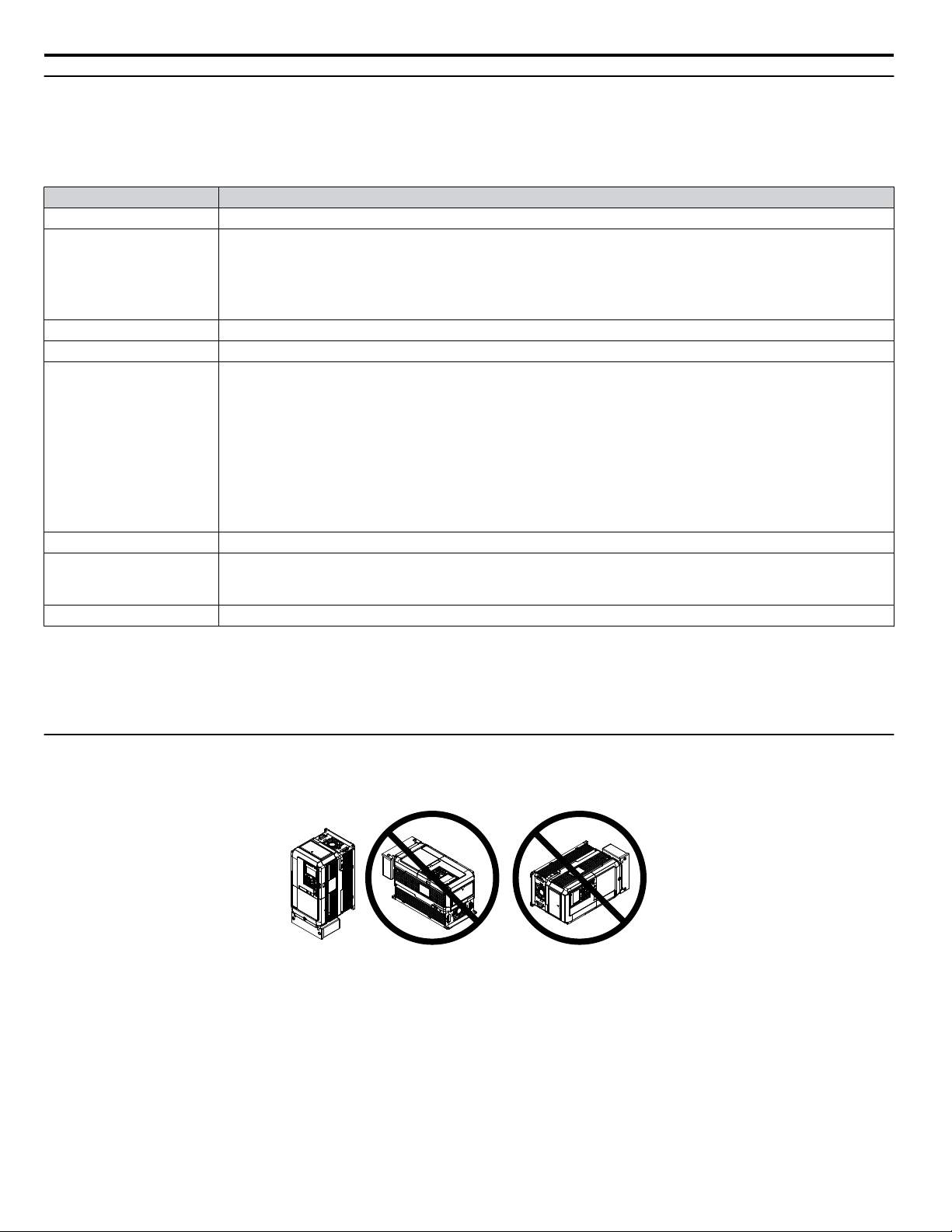
Installation Orientation and Spacing
Install the drive upright as illustrated in Figure i.1 to maintain proper cooling.
Figure i.1 Correct Installation Orientation
NOTICE: Install the drive upright as specified in the manual. Failure to comply may damage the drive due to improper cooling.
10
YASKAWA ELECTRIC TOEP YAIZ1U 02A YASKAWA AC Drive – Z1000 Safety Precautions
Page 11
A
A
B B
Side Clearance Top/Bottom Clearance
C
C
D
D
A
A
A
A
B
C
B
Side Clearance
Line up the tops of the drives.
D
D
Top/Bottom Clearance
i.2 Mechanical Installation Safety
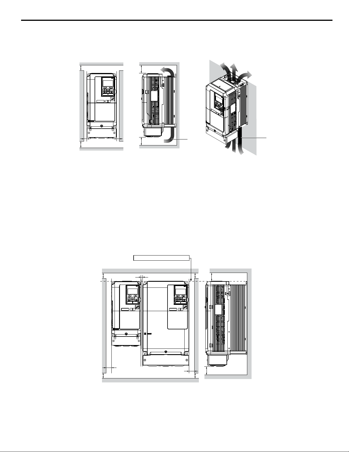
Single Drive Installation
n
Figure i.2 shows the installation distance required to maintain sufficient space for airflow and wiring. Install the heatsink
against a closed surface to avoid diverting cooling air around the heatsink.
A – 50 mm minimum
B – 30 mm minimum
C – 120 mm minimum
D – Airflow direction
Figure i.2 Correct Installation Spacing
Note: IP20/NEMA Type 1 enclosure and IP00/Open Type enclosure models require the same amount of space above and below the drive for
installation.
Multiple Drive Installation (Side-by-Side Installation)
n
Models 5A0003 to 5A0032 can take advantage of Side-by-Side installation.
When installing multiple drives into the same enclosure panel, mount the drives according to Figure i.2 and set L8-35,
Installation Method Selection, to 1 (Side-by-Side Mounting).
When mounting drives with the minimum clearance of 2 mm according to Figure i.3, set parameter L8-35 to 1 while
considering derating.
A – 50 mm minimum
B – 30 mm minimum
Note: Align the tops of the drives when installing drives of different heights in the same enclosure panel. Leave space between the tops and bottoms
of stacked drives for easier cooling fan replacement.
YASKAWA ELECTRIC TOEP YAIZ1U 02A YASKAWA AC Drive – Z1000 Safety Precautions
C – 2 mm minimum
D – 120 mm minimum
Figure i.3 Space Between Drives (Side-by-Side Mounting)
11
Page 12

i.2 Mechanical Installation Safety
Remove the top protective covers of all drives as shown in Figure i.4 when mounting IP20/NEMA Type 1 enclosure drives
side-by-side.
Figure i.4 IP20/NEMA 1 Side-by-Side Mounting in Enclosure
u
Drive Dimensions
NOTICE
Refer to the Z1000 User Manual TOEPYAIZ1U03 (600 V models) for IP20/NEMA Type 1, IP00/Open Chassis, drive
dimensions.
The 1000 Series CD-ROM No. TOECC71061615, packaged with the drive contains the Z1000 User Manual No.
TOEPYAIZ1U03 and additional 1000-Series manuals.
12
YASKAWA ELECTRIC TOEP YAIZ1U 02A YASKAWA AC Drive – Z1000 Safety Precautions
Page 13

i.3 Electrical Installation Safety
i.3 Electrical Installation Safety
NOTICE
Refer to the Z1000 User Manual (600 V models) TOEPYAIZ1U03 on the CD-ROM packaged with the product for more
information regarding the Electrical Installation and for complete product instructions necessary for proper installation, set-
up, troubleshooting and maintenance. CD-ROM part number TOECC71061615.
DANGER
Electrical Shock Hazard
Before servicing, disconnect all power to the equipment. The internal capacitor remains charged even after the power
supply is turned off. The charge indicator LED will extinguish when the DC bus voltage is below 50 Vdc. To prevent electric
shock, wait for at least the time specified on the warning label, once all indicators are OFF, measure for unsafe voltages to
confirm the drive is safe prior to servicing.
Failure to comply will result in death or serious injury.
WARNING
Make sure the protective earthing conductor complies with technical standards and local safety regulations.
Failure to comply may result in death or serious injury.
Always use appropriate equipment for Ground Fault Circuit Interrupters (GFCIs).
The drive can cause a residual current with a DC component in the protective earthing conductor. Where a residual current
operated protective or monitoring device is used for protection in case of direct or indirect contact, always use a type B GFCI
according to IEC/EN 60755.
WARNING
Electrical Shock Hazard
Do not operate equipment with covers removed.
Failure to comply could result in death or serious injury.
The diagrams in this section may show drives without covers or safety shields to show details. Be sure to reinstall covers or
shields before operating the drives and run the drives according to the instructions described in this manual.
Always ground the motor-side grounding terminal.
Improper equipment grounding could result in death or serious injury by contacting the motor case.
Do not perform work on the drive while wearing loose clothing, jewelry or without eye protection.
Failure to comply could result in death or serious injury.
Remove all metal objects such as watches and rings, secure loose clothing, and wear eye protection before beginning work
on the drive.
Do not remove covers or touch circuit boards while the power is on.
Failure to comply could result in death or serious injury.
Do not allow unqualified personnel to perform work on the drive.
Failure to comply could result in death or serious injury.
Installation, maintenance, inspection, and servicing must be performed only by authorized personnel familiar with
installation, adjustment, and maintenance of AC drives.
YASKAWA ELECTRIC TOEP YAIZ1U 02A YASKAWA AC Drive – Z1000 Safety Precautions
13
Page 14
i.3 Electrical Installation Safety
WARNING
Do not touch any terminals before the capacitors have fully discharged.
Failure to comply could result in death or serious injury.
Before wiring terminals, disconnect all power to the equipment. The internal capacitor remains charged even after the power
supply is turned off. After shutting off the power, wait for at least the amount of time specified on the drive before touching
any components.
Fire Hazard
Tighten all terminal screws to the specified tightening torque.
Loose electrical connections could result in death or serious injury by fire due to overheating of electrical connections.
Do not use improper combustible materials.
Failure to comply could result in death or serious injury by fire.
Do not install the drive to a combustible surface. Never place combustible materials on the drive.
Do not use an improper voltage source.
Failure to comply could result in death or serious injury by fire.
Verify that the rated voltage of the drive matches the voltage of the incoming power supply before applying power.
When installing dynamic braking options, perform all wiring exactly as specified in the wiring diagrams provided.
Failure to do so can result in fire. Improper wiring may damage braking components.
Shut off the drive with a magnetic contactor (MC) when a fault occurs in any external equipment such as braking
resistors. Failure to comply may cause resistor overheating, fire, and injury to personnel.
WARNING
Fire Hazard
Properly handle the HOA keypad battery.
Improper use of the battery may cause fire by explosion and personal injury. Correctly install the battery, paying attention
to polarity (+/-). Do not attempt to charge the battery or improperly disassemble the HOA keypad.
CAUTION
Do not carry the drive by the front cover or the terminal cover.
Failure to comply may cause the main body of the drive to fall, resulting in minor or moderate injury.
NOTICE
Observe proper electrostatic discharge procedures (ESD) when handling the drive and circuit boards.
Failure to comply may result in ESD damage to the drive circuitry.
Never connect or disconnect the motor from the drive while the drive is outputting voltage.
Improper equipment sequencing could result in damage to the drive.
Do not use unshielded cable for control wiring.
Failure to comply may cause electrical interference resulting in poor system performance. Use shielded, twisted-pair wires
and ground the shield to the ground terminal of the drive.
Do not allow unqualified personnel to use the product.
Failure to comply could result in damage to the drive or braking circuit.
Carefully review instruction manual TOBPC72060000 or TOBPC72060001 when connecting a dynamic braking option to
the drive.
14
YASKAWA ELECTRIC TOEP YAIZ1U 02A YASKAWA AC Drive – Z1000 Safety Precautions
Page 15

i.3 Electrical Installation Safety
NOTICE
Do not modify the drive circuitry.
Failure to comply could result in damage to the drive and will void warranty.
Yaskawa is not responsible for any modification of the product made by the user. This product must not be modified.
Check all the wiring to ensure that all connections are correct after installing the drive and connecting any other
devices.
Failure to comply could result in damage to the drive.
Do not connect power supply lines to output terminals U/T1, V/T2, or W/T3. Failure to comply will destroy the drive.
Be sure to perform a final check of all sequence wiring and other connections before turning on the power and also check
for short circuits on the control terminals, which may damage the drive.
To get the full performance life out of the electrolytic capacitors and circuit relays, refrain from switching the drive
power supply off and on more than once every 30 minutes. Frequent use can damage the drive. Use the drive to stop and
start the motor.
NOTICE
Do not heat or throw the battery into fire.
The battery remains in use even when power to the drive has been shut off. Be sure to also remove the battery in the HOA
keypad when the drive will be shut off for long periods of time. A dead battery left inside the HOA keypad may leak and
damage the keypad and drive. Be sure to replace the battery with a new one immediately after the expected lifespan has
passed or when the “bAT” error is displayed on the HOA keypad.
Be sure to observe the Perchlorate Best Management Practices (BMPs).
BMPs apply to primary lithium (manganese dioxide) coin batteries sold or distributed in California. Perchlorate Material
special handling may apply, please refer to: www.dtsc.ca.gov/hazardouswaste/perchlorate.
YASKAWA ELECTRIC TOEP YAIZ1U 02A YASKAWA AC Drive – Z1000 Safety Precautions
15
Page 16

i.4 Standard Connection Diagram
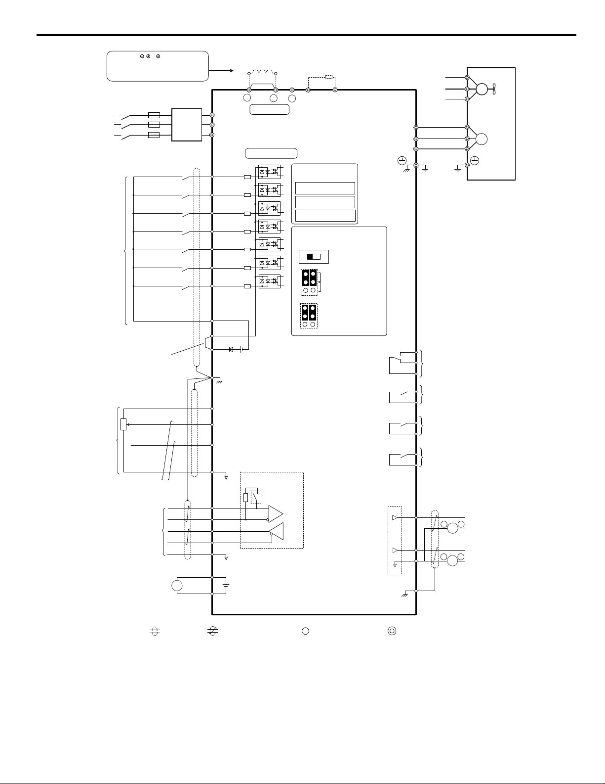
i.4 Standard Connection Diagram
Connect the drive and peripheral devices as shown in Figure i.5. It is possible to set and run the drive via the HOA keypad
without connecting digital I/O wiring.
WARNING! Fire Hazard. Install adequate branch circuit protection according to applicable local codes and this manual. Failure to comply
could result in fire and damage to the drive or injury to personnel. The device is suitable for use on a circuit capable of delivering not more
than 100,000 RMS symmetrical amperes 600 Vac maximum (600 V class), when protected by branch circuit protection devices specified
in this manual. Branch circuit protection shall be provided by any of the following: Non-time delay Class J, T, or CC fuses sized at 300% of
the drive input rating, or Time delay Class J, T, or CC fuses sized at 175% of the drive input rating, or MCCB sized at 200% maximum of
the drive input rating.
WARNING! Sudden Movement Hazard. Do not close the wiring for the control circuit unless the multifunction input terminal parameters are
properly set. Improper sequencing of run/stop circuitry could result in death or serious injury from moving equipment.
WARNING! Sudden Movement Hazard. Ensure start/stop and safety circuits are wired properly and in the correct state before energizing
the drive. Failure to comply could result in death or serious injury from moving equipment. When programmed for 3-Wire control, a momentary
closure on terminal S1 may cause the drive to start.
WARNING! Sudden Movement Hazard. When using a 3-Wire sequence, set the drive to 3-Wire sequence prior to wiring the control terminals
and set parameter b1-17 to 0 so the drive will not accept a Run command at power up (default). If the drive is wired for a 3-Wire sequence
but set up for a 2-Wire sequence (default), and parameter b1-17 is set to 1 so the drive accepts a Run command at power up, the motor
will rotate in reverse direction at drive power up and may cause injury.
WARNING! Sudden Movement Hazard. Confirm the drive I/O signals and external sequence before executing the application preset
function. Executing the application preset function or setting A1-06 ≠ 0 will change the drive I/O terminal functions and may cause unexpected
equipment operation. Failure to comply may cause death or serious injury.
NOTICE: When using the automatic fault restart function with wiring designed to shut off the power supply upon drive fault, make sure the
drive does not trigger a fault output during fault restart (L5-02 = 0, default). Failure to comply will prevent the automatic fault restart function
from working properly.
NOTICE: When the input voltage is 440 V or higher or the wiring distance is greater than 100 meters, pay special attention to the motor
insulation voltage or use a drive duty motor. Failure to comply could lead to motor insulation breakdown.
NOTICE: Do not connect AC control circuit ground to drive enclosure. Improper drive grounding can cause control circuit malfunction.
NOTICE: Route motor leads U/T1, V/T2, and W/T3 separate from all other leads to reduce possible interference related issues. Failure to
comply may result in abnormal operation of drive and nearby equipment.
Note: The minimum load for the relay outputs M1-M2, M3-M4, M5-M6, and MA-MB-MC is 10 mA.
16
YASKAWA ELECTRIC TOEP YAIZ1U 02A YASKAWA AC Drive – Z1000 Safety Precautions
Page 17
+
-
+
+
for connection options. Never
connect power supply lines to
these terminals
DC link choke
(option)
U X
+
-
+
+
+
-
U X
S1
S2
S3
S4
S5
S6
S7
A1
A2
0 V
AC
R
R
S
S-
IG
Z1000 Drive (600 V)
B11
B2
2 k
SC
0 V
FM
AM
AC
E (G)
<1>
<2>
<9>
<7>
<8>
<6>
<4>
<3>
-
+24 V
+V
M1
M2
Jumper
Braking resistor
(option)
Forward Run / Stop
Reverse Run / Stop
External fault
Fault reset
Multi-speed step 1
Multi-speed step 2
Jog speed
Multi-function
digtial inputs
(default setting)
Sink / Source mode
selection
Factory installed wire link
(default: Sink)
CN5-C
CN5-B
CN5-A
Option board
Shield ground terminal
Multi-function
analog inputs
Power supply +10.5 Vdc, max. 20 mA
Analog Input 1 (Frequency Reference Bias)
0 to +10 Vdc (20 kΩ) Resolution: Unsigned 12 bit
4 to 20 mA (250 Ω) / 0 to 20 mA (250 Ω)
MEMOBUS/Modbus Communication
RS-422/RS-485 Maximum 115.2 kbps
BACnet Communication
Apogee FLN, Siemens
Metasys N2, Johnson Controls
Termination resistor
(120 , 1/2 W)
DIP
Switch S2
Multi-function relay output (During Run)
250 Vac, max. 1 A
30 Vdc, max 1 A
(min. 5 Vdc, 10 mA)
Multi-function analog output 1
(Output frequency)
-10 to +10 or 0 to +10 Vdc (2 mA)
or 4 to 20 mA
Main Circuit
Control Circuit
shielded line
twisted-pair shielded line
main circuit terminal
control circuit terminal
R/L1
S/L2
T/L3
R
S
T
Main
Switch
Fuse
EMC
Filter
M3
M4
Multi-function relay output (Zero Speed)
250 Vac, max. 1 A
30 Vdc, max 1 A
(min. 5 Vdc, 10 mA)
SP
SN
AMFM
V
I
Off
On
DIP Switch S2
Term. Res. On/Off
Jumper S1
A1/A2 Voltage/Current
Selection
Jumper S5
AM/FM Voltage/Current
Selection
Terminal board
jumpers and switches
FM
<5>
<10>
Ω
<9>
Multi-function analog output 2
(Output current)
-10 to +10 or 0 to +10 Vdc (2 mA)
or 4 to 20 mA
Three-Phase
Power Supply
600 V
50/60 Hz
<11>
M
U/T1
V/T2
W/T
U
FU
FV
FW
V
W
3
Ground
Cooling fan
M
connectors
Ω
Analog Input 2 (Frequency Reference Bias)
0 to +10 Vdc (20 kΩ) Resolution: Unsigned 12 bit
4 to 20 mA (250 Ω) / 0 to 20 mA (250 Ω)
Fault output
250 Vac, max. 1 A
30 Vdc, max 1 A
(min. 5 Vdc, 10 mA)
MA
MB
MC
V
I
A1 A2
FE
M5
M6
Multi-function relay output (Speed Agree 1)
250 Vac, max. 1 A
30 Vdc, max 1 A
(min. 5 Vdc, 10 mA)
External power supply
24 Vdc, max. 150 ma
Terminals , 1, 2, B1, B2 are
+
-
AM
++
2
+P
SN
+24 Vdc
External
Supply
(max. 150 mA)
-
+
i.4 Standard Connection Diagram
<1> Remove the jumper when installing a DC link choke. Models 5A0041 to 5A0242 come with a built-in DC link choke.
<2> Set L8-55 to 0 to disable the protection function of the built-in braking transistor of the drive when using an optional regenerative
converter or dynamic braking option. Leaving L8-55 enabled may cause a braking resistor fault (rF). Additionally, disable Stall
Prevention (L3-04 = 0) when using an optional regenerative converter, regenerative or braking units, or dynamic braking option.
Leaving If L3-04 enabled may prevent the drive from stopping within the specified deceleration time.
<3> Supplying power to the control circuit separately from the main circuit requires 24 V power supply (option).
YASKAWA ELECTRIC TOEP YAIZ1U 02A YASKAWA AC Drive – Z1000 Safety Precautions
Figure i.5 Drive Standard Connection Diagram
17
Page 18

i.4 Standard Connection Diagram
<4> This figure illustrates an example of a sequence input to S1 through S7 using a non-powered relay or an NPN transistor. Install
the wire link between terminals SC-SP for Sink mode, between SC-SN for Source mode, or leave the link out for external power
supply. Never short terminals SP and SN, as it will damage the drive.
<5> This voltage source supplies a maximum current of 150 mA.
<6> The maximum output current capacity for the +V terminal on the control circuit is 20 mA. Never short terminals +V and AC, as
it can cause erroneous operation or damage the drive.
<7> Set jumper S1 to select between a voltage or current input signal to terminal A2. The default setting is for voltage input.
<8> Set DIP switch S2 to the ON position to enable the termination resistor in the last drive in a MEMOBUS/Modbus network.
<9> Monitor outputs work with devices such as analog frequency meters, ammeters, voltmeters, and wattmeters. They are not
intended for use as a feedback-type signal.
<10> Use jumper S5 to select between voltage or current output signals at terminals AM and FM. Set parameters H4-07 and H4-08
accordingly.
<11> Self-cooling motors do not require the same wiring necessary for motors with cooling fans.
u
Main Circuit Wiring
WARNING! Electrical Shock Hazard. Do not connect the AC power line to the drive output terminals U/T1, V/T2, and W/T3 . Failure to
comply could result in death or serious injury by fire as a result of drive damage from line voltage application to output terminals.
NOTICE
Refer to the Z1000 User Manual (600 V models) TOEPYAIZ1U03 on the CD-ROM packaged with the product for complete
product instructions necessary for proper installation, set-up, troubleshooting and maintenance. CD part number
TOECC71061615.
NOTICE: Route motor leads U/T1, V/T2, and W/T3 separate from all other leads to reduce possible interference related issues. Failure to
comply may result in abnormal operation of drive and nearby equipment.
NOTICE: Do not use the negative DC bus terminal “–” as a ground terminal. This terminal is at high DC voltage potential. Improper wiring
connections could damage the drive.
NOTICE: Do not solder the ends of wire connections to the drive. Soldered wiring connections can loosen over time. Improper wiring practices
could result in drive malfunction due to loose terminal connections.
NOTICE: Do not switch the drive input to start or stop the motor. Frequently switching the drive on and off shortens the life of the DC bus
charge circuit and the DC bus capacitors, and can cause premature drive failures. For the full performance life, refrain from switching the
drive on and off more than once every 30 minutes.
NOTICE: When connecting the motor to the drive output terminals U/T1, V/T2, and W/T3, the phase order for the drive and motor should
match. Failure to comply with proper wiring practices may cause the motor to run in reverse if the phase order is backward.
NOTICE: Do not connect phase-advancing capacitors or LC/RC noise filters to the output circuits. Failure to comply could result in damage
to the drive, phase-advancing capacitors, LC/RC noise filters or ground fault circuit interrupters.
Note: Wire gauge recommendations based on drive continuous current ratings (ND) using 75 °C 600 Vac vinyl-sheathed wire assuming ambient
temperature within 40 °C and wiring distance less than 100 m.
Yaskawa recommends using closed-loop crimp terminals on all drive models. To maintain UL/cUL approval, UL Listed
closed-loop crimp terminals are specifically required when wiring the drive main circuit terminals on models 5A0041 to
5A0242. Use only the tools recommended by the terminal manufacturer for crimping.
u
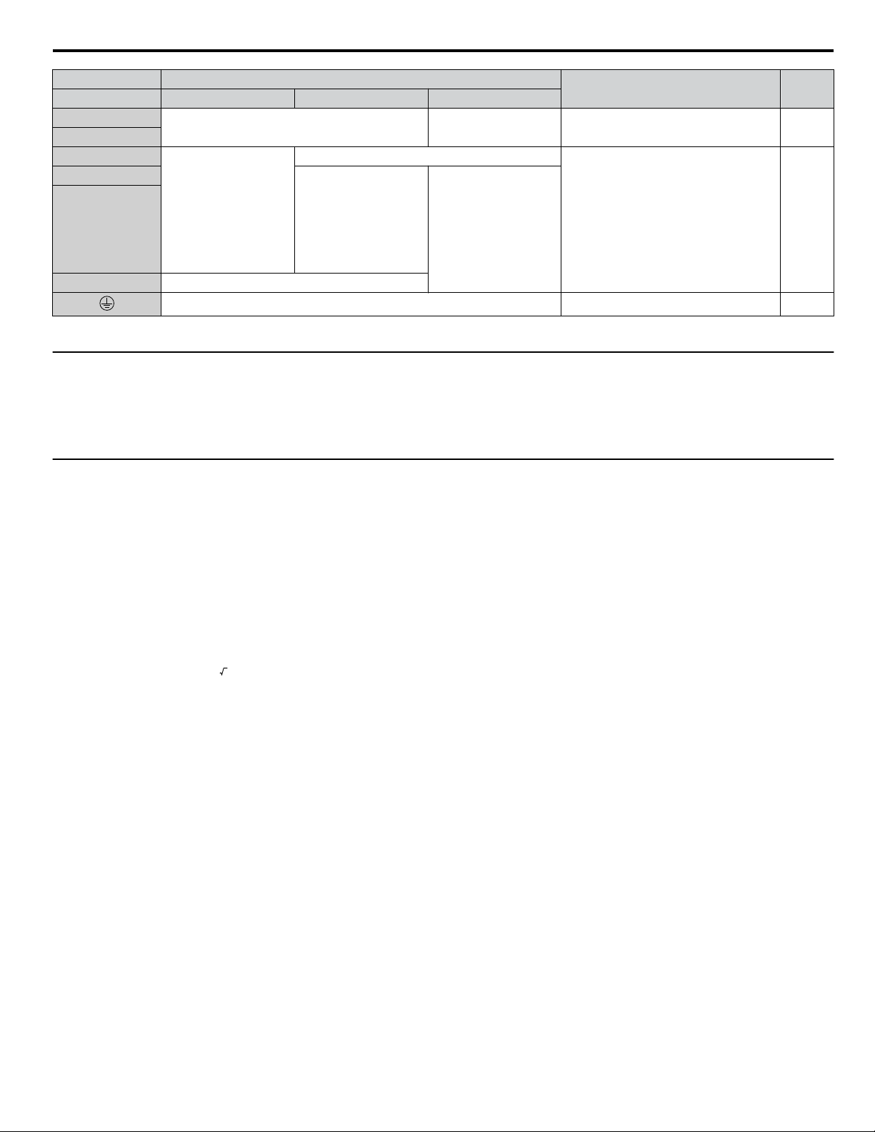
Main Circuit Terminal Functions
Table i.3 Main Circuit Terminal Functions
Terminal Type
Drive Model 5A0003 to 5A0032 5A0041, 5A0052 5A0062 to 5A0242
R/L1
Main circuit power supply input Connects line power to the drive 17S/L2
T/L3
U/T1
Drive output Connects to the motor 17V/T2
W/T3
Function Page
18
YASKAWA ELECTRIC TOEP YAIZ1U 02A YASKAWA AC Drive – Z1000 Safety Precautions
Page 19
i.4 Standard Connection Diagram
Terminal Type
Drive Model 5A0003 to 5A0032 5A0041, 5A0052 5A0062 to 5A0242
B1
B2
⊕2 • DC link choke
⊕1
⊖
⊕3
Note: Use terminals B1 and ⊖ when installing a CDBR-type braking unit on drives with built-in braking transistors (Models 5A0003 to 5A0052).
u
Protecting Main Circuit Terminals
Insulation Caps or Sleeves
n
connection
(⊕1, ⊕2)
(remove the shorting
bar between
⊕1 and ⊕2)
• DC power supply
input
(⊕1, ⊖)
Braking resistor Not available
Not available
DC power supply input
(⊕1, ⊖)
Not available
10 Ω or less Grounding terminal 24
• DC power supply
input (⊕1, ⊖)
• Braking unit
connection (⊕3, ⊖)
Available for connecting a braking
resistor or a braking resistor unit option
For connecting:
• the drive to a DC power supply
• dynamic braking options
• a DC link choke
Function Page
–
–
Use insulation caps or sleeves when wiring the drive with crimp terminals. Take particular care to ensure that the wiring does
not touch nearby terminals or the surrounding case.
u
Main Circuit Wire Gauges and Tightening Torque
Use the tables in this section to select the appropriate wires and crimp terminals.
Gauges listed in the tables are for use in the United States.
Note: 1. Wire gauge recommendations based on drive continuous current ratings (ND) using 75 °C 600 Vac vinyl-sheathed wire assuming ambient
temperature within 40 °C and wiring distance less than 100 m.
2. Terminals ⊕1, ⊕2, ⊕3, ⊖, B1 and B2 are for connecting optional power devices. Use caution to connect only approved devices to the
correct terminal(s).
• Consider the amount of voltage drop when selecting wire gauges. Increase the wire gauge when the voltage drop is greater
than 2% of motor rated voltage. Ensure the wire gauge is suitable for the terminal block. Use the following formula to
calculate the amount of voltage drop:
Line drop voltage (V) =
3 × wire resistance (Ω/km) × wire length (m) × current (A) × 10
-3
• Refer to instruction manual TOBP C720600 00 for braking transistor option or braking resistor option wire gauges.
• Use terminals ⊕1 and ⊖ when connecting a regenerative converter or a regen unit.
NOTICE: Do not connect a braking resistor to terminals ⊕1 or ⊖. Failure to comply may cause damage to the drive circuitry.
• Use terminals B1 and ⊖ when installing a CDBR-type braking unit on drives with built-in braking transistors (models
5A0003 to 5A0052).
NOTICE: Do not connect a braking resistor to terminals ⊕1 or ⊖. Failure to comply may cause damage to the drive circuitry.
• Refer to UL Standards Compliance on page 53 for information on UL compliance.
Yaskawa recommends using closed-loop crimp terminals on all drive models. Use only the tools recommended by the terminal
manufacturer for crimping. Refer to Closed-Loop Crimp Terminal Size on page 23 for closed-loop crimp terminal
recommendations.
The wire gauges listed below are Yaskawa recommendations. Refer to local codes for proper wire gauge selections.
YASKAWA ELECTRIC TOEP YAIZ1U 02A YASKAWA AC Drive – Z1000 Safety Precautions
19
Page 20

i.4 Standard Connection Diagram
Three-Phase 600 V Class
n
Table i.4 Wire Gauge and Torque Specifications (Three-Phase 600 V Class)
Drive Model Terminal
R/L1, S/L2, T/L3
U/T1, V/T2, W/T3
5A0003
5A0004
5A0006
5A0009
5A0011
5A0017
5A0022
⊖, ⊕1, ⊕2
B1, B2 –
R/L1, S/L2, T/L3
U/T1, V/T2, W/T3
⊖, ⊕1, ⊕2
B1, B2 –
R/L1, S/L2, T/L3
U/T1, V/T2, W/T3
⊖, ⊕1, ⊕2
B1, B2 –
R/L1, S/L2, T/L3
U/T1, V/T2, W/T3
⊖, ⊕1, ⊕2
B1, B2 –
R/L1, S/L2, T/L3
U/T1, V/T2, W/T3
⊖, ⊕1, ⊕2
B1, B2 –
Recomm. Gauge
mm2 (AWG, kcmil)
2.5
(14)
2.5
(14)
–
6.0
(10)
2.5
(14)
2.5
(14)
–
6.0
(10)
6.0
(10)
2.5
(14)
–
10
(8)
6.0
(10)
6.0
(10)
–
10
(8)
10
(8)
6.0
(10)
–
10
(8)
Wire Range
mm2 (AWG, kcmil)
2.5 to 6.0
(14 to 10)
2.5 to 6.0
(14 to 10)
2.5 to 6.0
(14 to 10)
2.5 to 6.0
(14 to 10)
2.5 to 6.0
(14 to 10)
2.5 to 6.0
(14 to 10)
2.5 to 6.0
(14 to 10)
2.5 to 6.0
(14 to 10)
2.5 to 6.0
(14 to 10)
4.0 to 6.0
(12 to 10)
2.5 to 16
(14 to 6)
2.5 to 16
(14 to 6)
2.5 to 16
(14 to 6)
2.5 to 6.0
(14 to 10)
4.0 to 6.0
(12 to 8)
6.0 to 16
(10 to 6)
6.0 to 16
(10 to 6)
6.0 to 16
(10 to 6)
6.0 to 10
(10 to 8)
6.0 to 10
(12 to 8)
6.0 to 16
(10 to 6)
6.0 to 16
(10 to 6)
6.0 to 16
(10 to 6)
6.0 to 10
(10 to 8)
6.0 to 10
(10 to 6)
Screw
Size
M4
M4
M4
M5
M5
M6
M5
M6
Tightening Torque
N·m (lb.in.)
1.2 to 1.5
(10.6 to 13.3)
1.2 to 1.5
(10.6 to 13.3)
2.1 to 2.3
(18.6 to 20.4)
2.0 to 2.5
(17.7 to 22.1)
3.6 to 4.0
(31.8 to 35.4)
2.7 to 3.0
(23.9 to 26.6)
5.4 to 6.0
(47.8 to 53.1)
3.6 to 4.0
(31.8 to 35.4)
2.7 to 3.0
(23.9 to 26.6)
5.4 to 6.0
(47.8 to 53.1)
20
YASKAWA ELECTRIC TOEP YAIZ1U 02A YASKAWA AC Drive – Z1000 Safety Precautions
Page 21

i.4 Standard Connection Diagram
Drive Model Terminal
R/L1, S/L2, T/L3
U/T1, V/T2, W/T3
5A0027
5A0032
5A0041
5A0052
5A0062
5A0077
5A0099
⊖, ⊕1, ⊕2
B1, B2 –
R/L1, S/L2, T/L3
U/T1, V/T2, W/T3
⊖, ⊕1
B1, B2 –
R/L1, S/L2, T/L3
U/T1, V/T2, W/T3
⊖, ⊕1
B1, B2 –
R/L1, S/L2, T/L3
U/T1, V/T2, W/T3
⊖, ⊕1
⊕3
R/L1, S/L2, T/L3
U/T1, V/T2, W/T3
⊖, ⊕1
⊕3
R/L1, S/L2, T/L3
U/T1, V/T2, W/T3
⊖, ⊕1
⊕3
Recomm. Gauge
mm2 (AWG, kcmil)
16
(6)
16
(6)
–
16
(6)
16
(6)
16
(6)
– (6 to 1)
16
(6)
25
(4)
16
(6)
–
16
(6)
25
(4)
25
(4)
–
–
25
(4)
25
(3)
25
(3)
–
–
25
(4)
70
(1/0)
50
(1)
–
–
25
(4)
Wire Range
mm2 (AWG, kcmil)
16 to 25
(6 to 4)
16 to 25
(6 to 4)
16 to 25
(6 to 4)
6.0 to 10
(10 to 8)
10 to 16
(10 to 6)
6.0 to 25
(10 to 3)
6.0 to 25
(10 to 3)
4.0 to 25
(12 to 3)
10 to 16
(6)
6.0 to 25
(10 to 3)
6.0 to 25
(10 to 3)
16 to 35
(6 to 1)
10 to 25
(8 to 3)
10 to 16
(6)
6.0 to 95
(10 to 4/0)
6.0 to 95
(10 to 4/0)
25 to 95
(4 to 4/0)
16 to 95
(6 to 4/0)
25
(4)
6.0 to 95
(10 to 4/0)
6.0 to 95
(10 to 4/0)
25 to 95
(3 to 4/0)
16 to 95
(6 to 4/0)
25
(4)
6.0 to 95
(10 to 4/0)
6.0 to 95
(10 to 4/0)
35 to 95
(2 to 4/0)
25 to 95
(4 to 4/0)
25
(4)
Screw
Size
M6
M5
M6
M8
M8
M10
M10
M10
Tightening Torque
N·m (lb.in.)
5.4 to 6.0
(47.8 to 53.1)
2.7 to 3.0
(23.9 to 26.6)
5.4 to 6.0
(47.8 to 53.1)
9.0 to 11
(79.7 to 97.4)
9.0 to 11
(79.7 to 97.4)
18 to 23
(159 to 204)
18 to 23
(159 to 204)
18 to 23
(159 to 204)
YASKAWA ELECTRIC TOEP YAIZ1U 02A YASKAWA AC Drive – Z1000 Safety Precautions
21
Page 22

i.4 Standard Connection Diagram
Drive Model Terminal
R/L1, S/L2, T/L3
U/T1, V/T2, W/T3
5A0125
5A0145
5A0192
5A0242
⊖, ⊕1
⊕3
R/L1, S/L2, T/L3
U/T1, V/T2, W/T3
⊖, ⊕1
⊕3
R/L1, S/L2, T/L3
U/T1, V/T2, W/T3
⊖, ⊕1
⊕3
R/L1, S/L2, T/L3
U/T1, V/T2, W/T3
⊖, ⊕1
⊕3
Recomm. Gauge
mm2 (AWG, kcmil)
70
(2/0)
70
(2/0)
–
–
35
(3)
95
(3/0)
95
(3/0)
–
–
35
(3)
185
(300)
150
(250)
–
–
50
(1)
240
(400)
185
(350)
–
–
50
(1)
Wire Range
mm2 (AWG, kcmil)
35 to 150
(1 to 300)
35 to 150
(1 to 300)
70
(2/0 to 3/0)
35 to 50
(1 to 1/0)
35 to 150
(3 to 300)
95 to 150
(2/0 to 300)
95 to 150
(2/0 to 300)
70 to 95
(3/0 to 4/0)
70 to 95
(1/0 to 2/0)
35 to 150
(3 to 300)
95 to 300
(2/0 to 600)
95 to 300
(2/0 to 600)
95 to 185
(2/0 to 400)
95 to 120
(2/0 to 250)
35 to 300
(1 to 350)
95 to 300
(2/0 to 600)
95 to 300
(2/0 to 600)
95 to 240
(2/0 to 500)
150
(250 to 300)
35 to 300
(1 to 350)
Screw
Size
M10
M10
M12
M10
M12
M12
M10
M12
Tightening Torque
N·m (lb.in.)
18 to 23
(159 to 204)
18 to 23
(159 to 204)
32 to 40
(283 to 354)
18 to 23
(159 to 204)
32 to 40
(283 to 354)
32 to 40
(283 to 354)
18 to 23
(159 to 204)
32 to 40
(283 to 354)
Note: When connecting peripheral devices or options to terminals ⊖, ⊕1, ⊕3, B1, and B2 , refer to the instruction manual for each device. For
more information, contact Yaskawa or your nearest sales representative.
22
YASKAWA ELECTRIC TOEP YAIZ1U 02A YASKAWA AC Drive – Z1000 Safety Precautions
Page 23

i.4 Standard Connection Diagram
Closed-Loop Crimp Terminal Recommendations
To maintain UL/cUL approval, UL Listed closed-loop crimp terminals are specifically required when wiring the drive main
circuit terminals on models 5A0041 to 5A0242. Use only the tools recommended by the terminal manufacturer for crimping.
Yaskawa recommends UL listed crimp terminals made by JST and Tokyo DIP (or equivalent) for the insulation cap. Table i.
5 matches the wire gauges and terminal screw sizes with Yaskawa-recommended crimp terminals, tools, and insulation caps.
Refer to the appropriate Wire Gauge and Torque Specifications table for the wire gauge and screw size for your drive model.
Place orders with a Yaskawa representative or the Yaskawa sales department.
The closed-loop crimp terminal sizes and values listed in Table i.5 are Yaskawa recommendations. Refer to local codes for
proper selections.
Table i.5 Closed-Loop Crimp Terminal Size
Wire Gauge
8 AWG
6 AWG
4 AWG
3 / 2 AWG
1 AWG
1/0 AWG
1/0 AWG × 2P
1 AWG × 2P
2 AWG × 2P
2/0 / 3/0 AWG
2/0 AWG × 2P
3/0 AWG × 2P
3/0 AWG × 4P
4/0 AWG M10 R100-10
4/0 AWG × 2P
4/0 AWG × 4P
250 / 300 kcmil
250 kcmil × 2P
250 kcmil × 4P
300 kcmil × 2P
300 kcmil × 4P
350 kcmil
400 kcmil
Terminal
Screws
M4 8-4 YA-4 AD-901 TP-008 100-054-031
M5 R8-5 YA-4 AD-901 TP-008 100-054-032
M8 R8-8 YA-4 AD-901 TP-008 100-061-111
M4 14-NK4 YA-4 AD-902 TP-014 100-054-033
M5 R14-5 YA-4 AD-902 TP-014 100-054-034
M6 R14-6 YA-5 AD-952 TP-014 100-051-261
M8 R14-8 YA-5 AD-952 TP-014 100-054-035
M10 R14-10 YA-5 AD-952 TP-014 100-061-112
M6 R22-6 YA-5 AD-953 TP-022 100-051-262
M8 R22-8 YA-5 AD-953 TP-022 100-051-263
M10 R22-10 YA-5 AD-953 TP-022 100-061-113
M8 R38-8 YA-5 AD-954 TP-038 100-051-264
M10 R38-10 YA-5 AD-954 TP-038 100-061-114
M8 R60-8 YA-5 AD-955 TP-060 100-051-265
M10 R60-10 YF-1, YET-300-1 TD-321, TD-311 TP-060 100-051-266
M10 38-L10 YF-1, YET-150-1 TD-224, TD-212 TP-038 100-051-556
M10 80-10 YF-1, YET-300-1 TD-323, TD-312 TP-080 100-051-267
M10 80-L10 YF-1, YET-150-1 TD-227, TD-214 TP-080 100-051-557
M12 80-L12 YF-1, YET-300-1 TD-323, TD-312 TP-080 100-051-558
M10 100-L10 YF-1, YET-150-1 TD-228, TD-214 TP-100 100-051-559
M12 100-L12 YF-1, YET-300-1 TD-324, TD-312 TP-100 100-051-560
M10 R150-10 YF-1. YET-150-1 TD-229, TD-215 TP-150 100-051-272
M12 R150-12 YF-1, YET-300-1 TD-325, TD-313 TP-150 100-051-273
M10 150-L10 YF-1, YET-150-1 TD-229, TD-215 TP-150 100-051-561
M12 150-L12 YF-1, YET-300-1 TD-325, TD-313 TP-150 100-051-562
M10 200-10 YF-1, YET-300-1 TD-327, TD-314 TP-200 100-051-563
M12 R200-12 YF-1, YET-300-1 TD-327, TD-314 TP-200 100-051-275
Crimp Terminal
Model Number
Machine No. Die Jaw
YF-1, YET-300-1
YF-1, YET-150-1
<1> Codes refer to a set of three crimp terminals and three insulation caps. Prepare input and output wiring using two sets for each connection.
Example 1: Models with 300 kcmil for both input and output require one set for input terminals and one set for output terminals, so the user should
order two sets of [100-051-272].
Example 2: Models with 4/0 AWG × 2P for both input and output require two sets for input terminals and two sets for output terminals, so the user
should order four sets of [100-051-560].
Note: Use crimp insulated terminals or insulated shrink tubing for wiring connections. Wires should have a continuous maximum allowable
temperature of 75 °C 600 Vac UL-approved vinyl-sheathed insulation.
Tool Insulation
TD-324, TD-312
TD-228, TD-214
Cap
Model No.
TP-100 100-051-269
Code
<1>
YASKAWA ELECTRIC TOEP YAIZ1U 02A YASKAWA AC Drive – Z1000 Safety Precautions
23
Page 24

i.4 Standard Connection Diagram
Ground Wiring
n
Follow the precautions below when wiring the ground for one drive or a series of drives.
WARNING! Electrical Shock Hazard. Make sure the protective earthing conductor complies with technical standards and local safety
regulations. Failure to comply may result in death or serious injury.
WARNING! Electrical Shock Hazard. Always use a ground wire that complies with technical standards on electrical equipment and minimize
the length of the ground wire. Improper equipment grounding may cause dangerous electrical potentials on equipment chassis, which could
result in death or serious injury.
WARNING! Electrical Shock Hazard. Be sure to ground the drive ground terminal (600 V class: ground to 10 Ω or less). Improper equipment
grounding could result in death or serious injury by contacting ungrounded electrical equipment.
NOTICE: Do not share the ground wire with other devices such as welding machines or large-current electrical equipment. Improper
equipment grounding could result in drive or equipment malfunction due to electrical interference.
NOTICE: When using more than one drive, ground multiple drives according to instructions. Improper equipment grounding could result in
abnormal operation of drive or equipment.
Refer to Figure i.6 when using multiple drives. Do not loop the ground wire.
Figure i.6 Multiple Drive Wiring
u
Control Circuit Connections
Drive parameters determine which functions apply to the multi-function digital inputs (S1 to S7), multi-function digital outputs
(M1 to M4), multi-function analog inputs (A1 to A3), and multi-function analog monitor output (FM, AM). The default setting
is listed next to each terminal in Figure i.5 on page 17.
WARNING! Sudden Movement Hazard. Always check the operation and wiring of control circuits after being wired. Operating a drive with
untested control circuits could result in death or serious injury.
WARNING! Sudden Movement Hazard. Confirm the drive I/O signals and external sequence before starting test run. Setting parameter
A1-06 may change the I/O terminal function automatically from the factory setting. Failure to comply may result in death or serious injury.
24
YASKAWA ELECTRIC TOEP YAIZ1U 02A YASKAWA AC Drive – Z1000 Safety Precautions
Page 25

u
IG R+ R- S+ S- +V AC A1 A2 FM AM AC
FE S1 S2 S3 S4 S5 S6 S7 SN SC SP +P
M3 M4 M6
M1 M2 M5
MA MB MC
IG R+ R- S+ S- +V AC A1 A2 FM AM AC
FE S1 S2 S3 S4 S5 S6 S7 SN SC SP +P
M3 M4 M6
M1 M2 M5
MA MB MC
Terminal Configuration
The control circuit terminals are arranged as shown in Figure i.7.
Figure i.7 Control Circuit Terminal Arrangement
u
Control Circuit Input Terminals
i.4 Standard Connection Diagram
Table i.6 lists the input terminals on the drive. Text in parenthesis indicates the default setting for each multi-function input.
Table i.6 Control Circuit Input Terminals
Type No. Terminal Name (Function) Function (Signal Level) Default Setting
Multi-function input 1
S1
(Closed: Forward run, Open: Stop)
Multi-function input 2
S2
(Closed: Reverse run, Open: Stop)
Multi-function input 3
S3
Multi-Function
Digital Inputs
Analog Inputs /
Pulse Train
Input
(External fault, N.O.)
Multi-function input 4
S4
(Fault reset)
Multi-function input 5
S5
(Multi-step speed reference 1)
Multi-function input 6
S6
(Multi-step speed reference 2)
Multi-function input 7
S7
(Jog reference)
SC Multi-function input common Multi-function input common
SP Digital input power supply +24 Vdc 24 Vdc power supply for digital inputs, 150 mA max (only when not using
SN Digital input power supply 0 V
+V Power supply for analog inputs 10.5 Vdc (max allowable current 20 mA)
Multi-function analog input 1
A1
(Frequency reference bias)
Multi-function analog input 2
A2
(Frequency reference bias)
AC Frequency reference common 0 V
FE Ground for shielded lines and option cards –
• Photocoupler
• 24 Vdc, 8 mA
• Refer to Sinking/Sourcing Mode for Digital Inputs on page 30.
digital input option DI-A3)
NOTICE: Do not jumper or short terminals SP and SN. Failure to
comply will damage the drive.
-10 to 10 Vdc, 0 to 10 Vdc (input impedance: 20 kΩ)
• -10 to 10 Vdc, 0 to 10 Vdc (input impedance: 20 kΩ)
• 4 to 20 mA, 0 to 20 mA (input impedance: 250 Ω)
• Voltage or current input must be selected by DIP switch S1 and H3-09.
YASKAWA ELECTRIC TOEP YAIZ1U 02A YASKAWA AC Drive – Z1000 Safety Precautions
25
Page 26

i.4 Standard Connection Diagram
u
Control Circuit Output Terminals
Table i.7 lists the output terminals on the drive. Text in parenthesis indicates the default setting for each multi-function output.
Table i.7 Control Circuit Output Terminals
Type No. Terminal Name (Function) Function (Signal Level) Default Setting
Fault Relay
Output
Multi-Function
Digital Output
<1>
Monitor Output
External Power
Supply
<1> Refrain from assigning functions to digital relay outputs that involve frequent switching, as doing so may shorten relay performance life. Switching
life is estimated at 200,000 times (assumes 1 A, resistive load).
MA N.O. output (Fault)
MB N.C. output (Fault)
MC Fault output common
M1
Multi-function digital output (During run)
M2
M3
Multi-function digital output (Zero speed)
M4
M5
Multi-function digital output (Speed Agree 1)
M6
FM Analog monitor output 1 (Output frequency) 0 to 10 V / 0 to 100%
AM Analog monitor output 2 (Output current)
AC Monitor common 0 V
+P External Power Supply 24 V (Max. 150 mA)
30 Vdc, 10 mA to 1 A; 250 Vac, 10 mA to 1 A
Minimum load: 5 Vdc, 10 mA
30 Vdc, 10 mA to 1 A; 250 Vac, 10 mA to 1 A
Minimum load: 5 Vdc, 10 mA
4 to 20 mA / 0 to 100%
Voltage or current output must be selected by Jumper S5 and H4-07
for FM and H4-08 for AM.
Connect a suppression diode as shown in Figure i.8 when driving a reactive load such as a relay coil. Ensure the diode rating
is greater than the circuit voltage.
B
A
A – External power, 48 V max.
B – Suppression diode
Figure i.8 Connecting a Suppression Diode
Serial Communication Terminals
n
Table i.8 Control Circuit Terminals: Serial Communications
Type No. Signal Name Function (Signal Level)
R+ Communications input (+)
R- Communications input (-)
S+ Communications output (+)
Serial Communication
(APOGEE FLN,
BACnet, MEMOBUS/
Modbus, or Metasys
<1>
N2)
<1> Enable the termination resistor in the last drive in an APOGEE FLN, BACnet, MEMOBUS/Modbus, or Metasys N2 network by setting DIP switch
S2 to the ON position.
S- Communications output (-)
IG Communications ground 0 V
FE Option card ground –
C
D
C – Coil
D – 50 mA or less
APOGEE FLN, BACnet, MEMOBUS/
Modbus, or Metasys N2 communication: Use
an RS-422 or RS-485 cable to connect the
drive.
• APOGEE FLN
Comm. RS-422/
RS-485, 4.8 kbps
• BACnet Comm.
RS-485, max. 76.8
kbps
• MEMOBUS/
Modbus Comm.
RS-422/RS-485,
max. 115.2 kbps
• Metasys N2 Comm.
RS-422/RS-485, 9.6
kbps
26
YASKAWA ELECTRIC TOEP YAIZ1U 02A YASKAWA AC Drive – Z1000 Safety Precautions
Page 27

i.4 Standard Connection Diagram
Wire Size and Torque Specifications
n
Select appropriate wire type and gauges from Table i.9. For simpler and more reliable wiring, use crimp ferrules on the wire
ends.
Table i.9 Wire Gauges
Tightening
Terminal
S1-S7, SC, SN, SP
V+, A1, A2, AC
MA, MB, MC
M1-M6
FM, AM, AC
R+, R-, S+, S-, IG
u
Wiring the Control Circuit Terminal
Screw
Size
M3
Torque
N•m
(lb. in)
0.5 to 0.6
(4.4 to 5.3)
Bare Wire Terminal Ferrule-Type Terminal
Recomm.
wire size
mm2 (AWG)
0.75 (18)
Applicable
wire size
mm2 (AWG)
Stranded wire:
0.2 to 1.0
(24 to 16)
Solid wire:
0.2 to 1.5
(24 to 16)
Recomm.
wire size
mm2 (AWG)
0.5 (20)
Applicable
wire size
mm2 (AWG)
0.25 to 0.5
(24 to 20)
Wire Type
Shielded wire,
etc.
This section describes the proper procedures and preparations for wiring the control terminals.
WARNING! Electrical Shock Hazard. Do not remove covers or touch the circuit boards while the power is on. Failure to comply could result
in death or serious injury.
NOTICE: Separate control circuit wiring from main circuit wiring (terminals R/L1, S/L2, T/L3, B1, B2, U/T1, V/T2, W/T3, ⊖, ⊕1, ⊕2) and
other high-power lines. Improper wiring practices could result in drive malfunction due to electrical interference.
NOTICE: Separate wiring for digital output terminals MA, MB, MC, and M1 to M6 from wiring to other control circuit lines. Improper wiring
practices could result in drive or equipment malfunction or nuisance trips.
NOTICE: Use a class 2 power supply when connecting to the control terminals. Improper application of peripheral devices could result in
drive performance degradation due to improper power supply. Refer to NEC Article 725 Class 1, Class 2, and Class 3 Remote-Control,
Signaling, and Power Limited Circuits for requirements concerning class 2 power supplies.
NOTICE: Insulate shields with tape or shrink tubing to prevent contact with other signal lines and equipment. Improper wiring practices could
result in drive or equipment malfunction due to short circuit.
NOTICE: Connect the shield of shielded cable to the appropriate ground terminal. Improper equipment grounding could result in drive or
equipment malfunction or nuisance trips.
NOTICE: Do not tighten screws beyond the specified tightening torque. Failure to comply may result in erroneous operation, damage to the
terminal block, or cause a fire.
NOTICE: Use shielded twisted-pair cables as indicated to prevent operating faults. Improper wiring practices could result in drive or
equipment malfunction due to electrical interference.
Wire the control circuit only after terminals have been properly grounded and main circuit wiring is complete. Refer to
Terminal Board Wiring Guide on page 28 for details. Prepare the ends of control circuit wiring as shown in Figure i.11.
Connect control wires as shown in Figure i.9 and Figure i.10.
YASKAWA ELECTRIC TOEP YAIZ1U 02A YASKAWA AC Drive – Z1000 Safety Precautions
27
Page 28

A
E
B
C
D
i.4 Standard Connection Diagram
A
A – Loosen screw to insert wire.
B – Single wire or stranded wire
Figure i.9 Terminal Board Wiring Guide
B
Preparing wire
terminal ends
C
D
C – Avoid fraying wire strands when
stripping insulation from wire. Strip
length 5.5 mm.
D – Blade depth of 0.4 mm or less
Blade width of 2.5 mm or less
Figure i.10 Terminal Board Location Inside the Drive
When setting the frequency by analog reference from an external potentiometer, use shielded twisted-pair wires (preparing
wire ends as shown in Figure i.11) and connect the shield to the ground terminal of the drive.
A – Drive side
B – Insulation
C – Control device side
Figure i.11 Preparing the Ends of Shielded Cables
NOTICE: The analog signal wiring between the drive and the operator station or peripheral equipment should not exceed 50 meters when
using an analog signal from a remote source to supply the frequency reference. Failure to comply could result in poor system performance.
28
YASKAWA ELECTRIC TOEP YAIZ1U 02A YASKAWA AC Drive – Z1000 Safety Precautions
D – Shield sheath (insulate with tape)
E – Shield
Page 29

IG R+ R- S+ S- +V AC A1 A2 FM AM AC
FE S1 S2 S3 S4 S5 S6 S7 SN SC SP +P
M3 M4 M6
M1 M2 M5
MA MB MC
Jumper S5
Terminal AM/FM
Signal Selection
FM AM
V
I
DIP Switch S2
RS-422/485 Termination
Resistor
Off On
Jumper S1
A1/A2 Voltage/Current
Selection
V
I
A1 A2
i.4 Standard Connection Diagram
u
Switches and Jumpers on the Terminal Board
The terminal board is equipped with several switches used to adapt the drive I/Os to the external control signals. Figure i.
12 shows the location of these switches.
Figure i.12 Locations of Jumpers and Switches on the Terminal Board
YASKAWA ELECTRIC TOEP YAIZ1U 02A YASKAWA AC Drive – Z1000 Safety Precautions
29
Page 30

SC
S8
S7
24 Vdc
SP
SN
External
24 Vdc
A2A1
V
I
A2A1
V
I
A2A1
V
I
A2A1
V
I
i.4 Standard Connection Diagram
u
Sinking/Sourcing Mode for Digital Inputs
Use the wire jumper between terminals SC and SP or SC and SN to select between Sink mode, Source mode or external power
supply for the digital inputs S1 to S7 as shown in Table i.10 (Default: Sink mode, internal power supply).
NOTICE: Do not short terminals SP and SN. Failure to comply will damage the drive.
Table i.10 Digital Input Sink/Source/External Power Supply Selection
Mode
Drive Internal Power Supply
(Terminals SN and SP)
S7
S8
External 24 Vdc Power Supply
Sinking Mode (NPN)
Sourcing Mode (PNP)
u
Input Signal Selection for Terminals A1 and A2
SN
SC
SP
S7
S8
SN
SC
SP
24 Vdc
24 Vdc
External
24 Vdc
S7
S8
SN
SC
24 Vdc
SP
Terminals A1 and A2 can be used to input either a voltage or a current signal. Select the signal type using jumper S1 as
explained in Table i.11. Set parameters H3-01 and H3-09 accordingly as shown in Table i.12.
Note: If terminals A1 and A2 are both set for frequency bias (H3-02 = 0 and H3-10 = 0), both input values will be combined to create the frequency
reference.
Table i.11 Jumper S1 Settings
Terminal Voltage Output Current Output
Terminal A1
Terminal A2
30
YASKAWA ELECTRIC TOEP YAIZ1U 02A YASKAWA AC Drive – Z1000 Safety Precautions
Page 31

i.4 Standard Connection Diagram
Table i.12 Parameters H3-01 and H3-09 Details
No. Parameter Name Description
Setting
Range
Default
Setting
Selects the signal level for terminal A1.
0: 0 to 10 V with Zero Limit
H3-01 Terminal A1 signal level selection
1: 0 to 10 V without Zero Limit
0 to 3 0
2: 4 to 20 mA Current Input
3: 0 to 20 mA Current Input
Selects the signal level for terminal A2.
0: 0 to 10 V with Zero Limit
H3-09 Terminal A2 signal level selection
1: 0 to 10 V without Zero Limit
0 to 3 0
2: 4 to 20 mA Current Input
3: 0 to 20 mA Current Input
u
Terminal FM/AM Signal Selection
The signal type for terminals FM and AM can be set to either voltage or current output using jumper S5 on the terminal board
as explained in Table i.13. When changing the setting of jumper S5, parameters H4-07 and H4-08 must be set accordingly.
The default selection is voltage output for both terminals.
Table i.13 Jumper S5 Settings
Terminal Voltage Output Current Output
Terminal FM
Terminal AM
V
I
AMFM
V
I
AMFM
V
I
AMFM
V
I
AMFM
Table i.14 Parameter H4-07 and H4-08 Details
No. Parameter Name Description
H4-07 Terminal FM signal level selection
H4-08 Terminal AM signal level selection
u
MEMOBUS/Modbus Termination
0: 0 to 10 Vdc
2: 4 to 20 mA
Setting
Range
0, 2 0
Default
Setting
This drive is equipped with a built-in termination resistor for the RS-422/485 communication port. DIP switch S2 enables or
disabled the termination resistor as shown in Table i.15. The OFF position is the default. The termination resistor should be
placed to the ON position when the drive is the last in a series of slave drives. Refer to Switches and Jumpers on the Terminal
Board on page 29 to locate switch S2.
Table i.15 MEMOBUS/Modbus Switch Settings
S2 Position Description
ON Internal termination resistor ON
OFF Internal termination resistor OFF (default setting)
YASKAWA ELECTRIC TOEP YAIZ1U 02A YASKAWA AC Drive – Z1000 Safety Precautions
31
Page 32

F2F1
ESC
M M
AUTO OFF
ENTERRESET
ALM
DIGITAL OPERATOR JVOP-183
HAND
12
11
9
8
1
2
3
10
4 5 6 7
AUTO
OFF
HAND
AUTO
HAND
i.5 HOA Keypad Operation
i.5 HOA Keypad Operation
u
HOA Keypad and Keys
Use the HOA keypad to enter OFF commands, switch AUTO or HAND Mode, change parameters, and display data including
fault and alarm information.
Figure i.13 Keys and Displays on the HOA Keypad
Keys and Functions
n
No. Display Name Function
1
F1
F2
Function Key
(F1, F2)
The functions assigned to F1 and F2 vary depending on the currently displayed menu. The name of
each function appears in the lower half of the display window.
• Returns to the previous display.
2
ESC
ESC Key
• Moves the cursor one space to the left.
• Pressing and holding this button will return to the Frequency Reference display.
3 RESET Key
• Moves the cursor to the right.
• Resets the drive to clear a fault situation.
Selects the source of Run command and frequency reference.
4
AUTO Key
• Set the drive to AUTO mode.
• Run command input source depends on b1-02.
• Frequency reference input source depends on b1-01.
5 Up Arrow Key Scrolls up to display the next item, selects parameter numbers, and increments setting values.
6 Down Arrow Key Scrolls down to display the previous item, selects parameter numbers, and decrements setting values.
7
8 ENTER Key
OFF Key Follows the stopping method set in b1-03 to stop drive operation.
• Enters parameter values and settings.
• Selects a menu item to move between displays.
The drive runs at a selectable frequency reference source by b1-12.
9
HAND Key
• Set the drive to HAND mode.
• When b1-13 is set to 1, HAND and AUTO mode can be switched while the drive is running.
10
11
AUTO Light Lit while the drive is in AUTO mode.
HAND Light Lit while the drive is in HAND mode.
12 ALM LED Light Lit when the drive detects an alarm or error.
YASKAWA ELECTRIC TOEP YAIZ1U 02A YASKAWA AC Drive – Z1000 Safety Precautions
32
Page 33

u
- MODE -
U1-01= 0.00Hz
U1-02= 0.00Hz
U1-03= 0.00A
DRV
Freq Ref (OPR)
Rdy
<3>
<4>
- MODE -
U1-01= 0.00Hz
U1-02= 0.00Hz
U1-03= 0.00A
DRV
Monitor Menu
Rdy
- MODE - PRG
Modified Consts
HELP
HELP
DATA
- MODE - PRG
Quick Setting
DATA
HELP
- MODE - PRG Rdy
Auto-Tuning
DATA
HELP
- MODE - PRG
DATA
Programming
AUTO
-MONITR-
U1 -01= 0.00Hz
U1-02= 0.00Hz
U1-03= 0.00A
DRV
Monitor
JOG
Rdy
-MONITR-
U1- 01 = 0.00Hz
U1-02= 0.00Hz
U1-03= 0.00A
DRV
Frequency Ref
JOG
Rdy
-MONITR-
U1- 02 = 0.00Hz
U1-03= 0.00A
U1-04= 0
DRV
Output Freq
JOG
Rdy
-MONITR-
U2 -01= oC
U2-02= oPr
U2-03= 0.00Hz
DRV
Fault Trace
JOG
Rdy
FWD
JOG
FWD
FWD
FWD
FWD
Modified
X Parameters
LSEQ
LREF
LSEQ
LREF
LSEQ
LREF
LSEQ
LREF
LSEQ
LREF
LSEQ
LREF
YASKAWA
Z1000
XXXV, XXXHP
XXXA
<XXXXXXXXX>
CIMR-ZXXXXXXXXX
Initial Display <5>
<6>
Programming Mode <2> Drive Mode <1>
FWD
FWD
FWD
FWD
FWD
AUTO
HAND
0
Menu Structure for HOA Keypad
i.5 HOA Keypad Operation
Figure i.14 HOA Keypad Menu and Screen Structure
<1>
Pressing
<2> Drive cannot operate motor.
<3> Flashing characters are shown with white letters on gray background. (Example:
<4> “X” characters are used as examples in this manual. The HOA keypad will display the actual setting values.
or
will start the motor.
)
<5> The Frequency Reference appears after the initial display that shows the product name.
<6> The information that appears on the display will vary depending on the drive.
YASKAWA ELECTRIC TOEP YAIZ1U 02A YASKAWA AC Drive – Z1000 Safety Precautions
33
Page 34

YES
NO
START
Install and wire the drive.
Apply main power on to the drive.
Adhere to safety messages concerning application of power.
Application Presets
A1-06 used?
Set the control mode in parameter A1-02.
Refer to
Application
Selection
Set the basic parameters
b1-01/02 for frequency reference and run command source selection
H1-
oo, H2-oo, H3-oo, H4-oo for I/O terminal setting
d1-
oo for multi-speed references if used
C1-
oo and C2-oo for accel./decel. and S-curve time settings
Fine tune parameters. Adjust application settings (PI, ...) if necessary.
Check the machine operation and verify parameter settings.
Drive is ready to run the application.
E1-01 for input voltage setting
i.6 Start Up
i.6 Start Up
u
Drive Setup Procedure
Flowchart A in Figure i.15 describes a basic start-up sequence that varies slightly depending on the application. Use the drive
default parameter settings in simple applications that do not require high precision.
Note: 1. Execute Stationary Auto-Tuning for Line-to-Line Resistance if the drive has been Auto-Tuned and then moved to a different location
u
Power On
where the motor cable length exceeds 50 m.
2. Perform Auto-Tuning again after installing an AC reactor or other such components to the output side of the drive.
Before turning on the power supply:
• Make sure all wires are connected properly.
• Make sure no screws, loose wire ends or tools are left in the drive.
• After turning the power on, the drive mode display should appear and no fault or alarm should be displayed.
u
Auto-Tuning
Figure i.15 Basic Start-Up
The drive offers different types of Auto-Tuning for induction motors and permanent magnet motors. The type of Auto-Tuning
used differs further based on the control mode and other operating conditions. Refer to the tables below to select the type of
Auto-Tuning that bests suits the application.
34
YASKAWA ELECTRIC TOEP YAIZ1U 02A YASKAWA AC Drive – Z1000 Safety Precautions
Page 35

i.6 Start Up
Table i.16 Types of Auto-Tuning for Induction Motors
Control
Type Setting Application Conditions and Benefits
Stationary Auto-Tuning for Lineto-Line Resistance
Rotational Auto-Tuning for V/f
Control
T1-01 = 2
T1-01 = 3
• The drive is used in V/f Control and other Auto-Tuning selections are not
possible.
• Drive and motor capacities differ.
• Tunes the drive after the cable between the drive and motor has been replaced
with a cable over 50 m long. Assumes Auto-Tuning has already been
performed.
• Should not be used for any vector control modes unless the motor cable has
changed.
• Recommended for applications using Speed Estimation Speed Search or using
the Energy Saving function in
V/f Control.
• Assumes motor can rotate while Auto-Tuning is executed. Increases accuracy
for certain functions like torque compensation, slip compensation, Energy
Saving, and Speed Search.
Mode
V/f
YES
YES
Table i.17 lists the data that must be entered for Auto-Tuning. Make sure this data is available before starting Auto-Tuning.
The necessary information is usually listed on the motor nameplate or in the motor test report provided by the motor
manufacturer.
Table i.17 Auto-Tuning Input Data
Tuning Type (T1-01)
Input Value Input Parameter Unit
Line-to-Line Resistance
Motor rated power T1-02 kW YES YES
Motor rated voltage T1-03 Vac – YES
Motor rated current T1-04 A YES YES
Motor rated frequency T1-05 Hz – YES
Number of motor poles T1-06 - – YES
Motor rated Speed T1-07 r/min – YES
Motor iron loss T1-11 W – YES
2
Rotational for V/f
3
Control
Table i.18 Types of Auto-Tuning for Permanent Magnet Motors
Type Setting Application Conditions and Benefits
PM Motor Parameter
Settings
T2-01 = 0
• Motor does not rotate during Auto-Tuning.
• Motor test report or motor data similar to Table i.19 are available.
Control Mode
OLV/PM
YES
Table i.19 lists the data that must be entered for Auto-Tuning. Make sure the data is available before starting Auto-Tuning.
The necessary information is usually listed on the motor nameplate or in the motor test report provided by the motor
manufacturer.
Table i.19 Auto-Tuning Input Data
Tuning Type (T2-01)
Input Value Input Parameter Unit
Control Mode A1-02 – 5
Motor Type T2-03 – –
Motor Rated Power T2-04 kW YES
Motor Rated Voltage T2-05 Vac YES
Motor Rated Current T2-06 A YES
Motor Rated Frequency T2-07 Hz YES
Number of Motor Poles T2-08 – YES
Stator Single-phase Resistance T2-10 Ω YES
Motor Parameter
0
Settings
YASKAWA ELECTRIC TOEP YAIZ1U 02A YASKAWA AC Drive – Z1000 Safety Precautions
35
Page 36
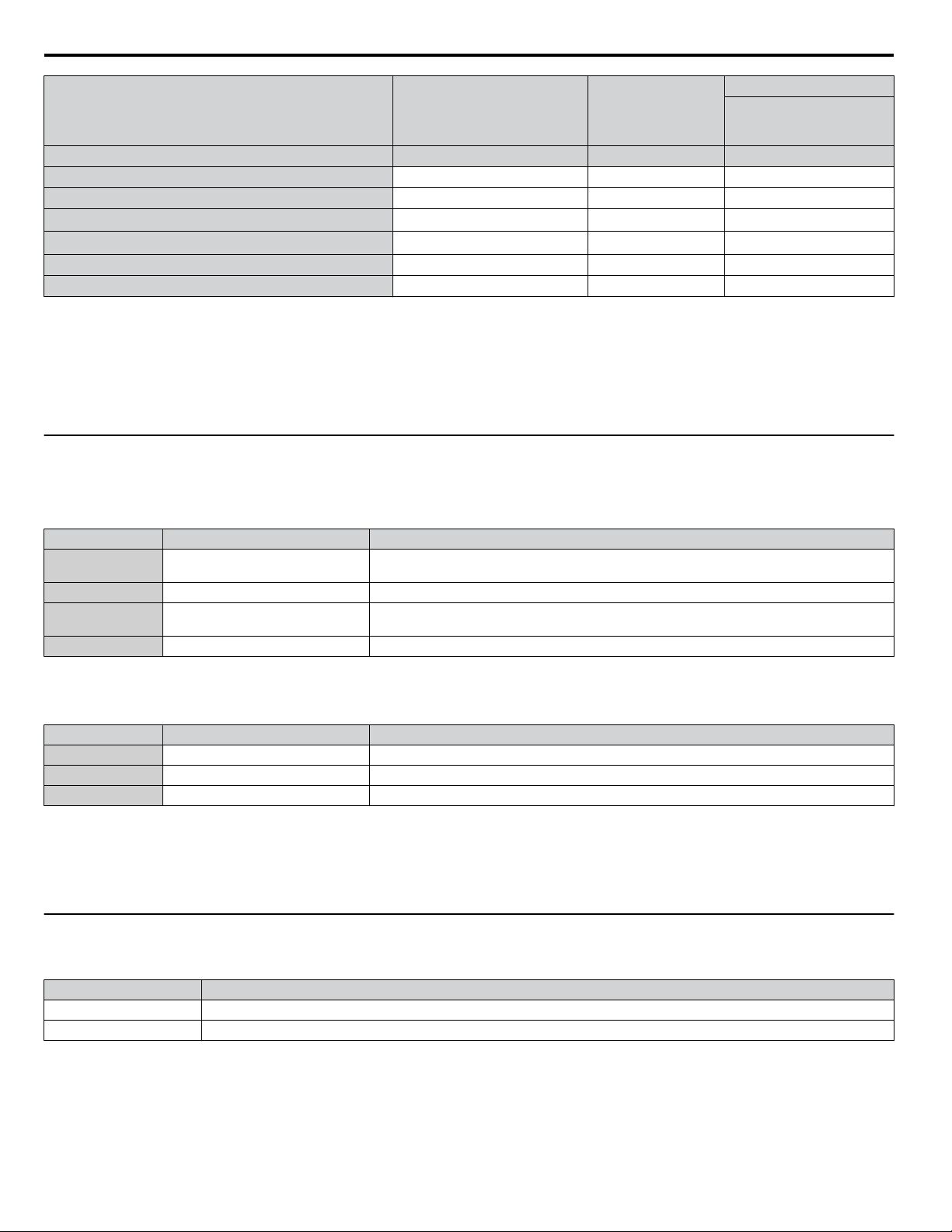
i.6 Start Up
Tuning Type (T2-01)
Input Value Input Parameter Unit
Control Mode A1-02 – 5
d-Axis Inductance T2-11 mH YES
q-Axis Inductance T2-12 mH YES
Induced Voltage Constant Unit Selection
Voltage Constant
Tuning Pull-in Current T2-15 A –
T2 Tuning Start T2-18 – YES
<1> It is only necessary to input either T2-13 or T2-14. Select one and leave the other empty.
<2> Dependent upon T2-13 setting.
WARNING! Electrical Shock Hazard. High voltage will be supplied to the motor when Stationary Auto-Tuning is performed even with the
motor stopped, which could result in death or serious injury. Do not touch the motor until Auto-Tuning has been completed.
<1> <2>
<1>
T2-13 mVs/rad (elec.) YES
T2-14 mVmin (mech.) YES
Motor Parameter
0
Settings
When Auto-Tuning cannot be performed, set up the maximum frequency and voltage in the E1-oo parameters and enter the
motor data manually into the E2-oo parameters.
u
External Reference Selection and Acceleration/Deceleration Times
b1-01: Frequency Reference Selection for AUTO Mode
n
Set parameter b1-01 according to the frequency reference used.
b1-01 Reference Source Frequency Reference Input
0 HOA keypad
1 Analog input terminals Apply the frequency reference signal to terminal A1 or A2.
2 Serial communications
3 Option PCB Communications option card
b1-02: Run Command Selection for AUTO Mode
n
Set the frequency references in the d1-oo parameters and use digital inputs to switch over between
different reference values.
Serial Communications using the RS-422/RS-485 serial communications port (control terminals R
+, R-, S+, and S-).
Set parameter b1-02 according to the Run command selection for AUTO mode.
b1-02 Reference Source Run Command Input
1 Digital input terminals Multi-Function digital input
2 Serial communications Serial Communications using the RS-422/RS-485 port
3 Option PCB Communications option card
Acceleration/ Deceleration Times and S-Curves
n
There are two sets of acceleration and deceleration times which can be set in the C1-oo parameters. The default activated
accel/decel times are C1-01/C1-02. Adjust these times to the appropriate values required by the application. If necessary, Scurves can be activated in the C2-oo parameters for softer accel/decel start and end.
u
Reference and Run Source
The drive has a LOCAL and a REMOTE mode.
Status Description
LOCAL The Run/Stop command and the frequency reference are entered at the operator keypad.
REMOTE The Run command source entered in parameter b1-02 and the frequency reference source entered in parameter b1-01 are used.
If the drive is operated in the REMOTE mode, make sure that the correct sources for the frequency reference and run command
are set in parameters b1-01/b1-02 and that the drive is in the REMOTE mode.
The LED in the LO/RE key indicates where the Run command is input from.
36
YASKAWA ELECTRIC TOEP YAIZ1U 02A YASKAWA AC Drive – Z1000 Safety Precautions
Page 37

i.6 Start Up
LO/RE LED Description
ON Run command is issued from operator.
OFF Run command is issued from a different source than the operator.
u
I/O Setup
The default setting functions can be seen in the connection diagram on page 17.
Multi-Function Digital Inputs (H1-oo)
n
The function of each digital input can be assigned in the H1-oo parameters.
Multi-Function Digital Outputs (H2-oo)
n
The function of each digital output can be assigned in the H2-oo parameters. The setting value of these parameters consist
of 3 digits, where the middle and right digit set the function and the left digit sets the output characteristics (0: Output as
selected; 1: Inverse output).
Multi-Function Analog Inputs (H3-oo)
n
The function of each analog input can be assigned in the H3-oo parameters. Input A1 and A3 are set for -10 to +10 VDC
input. A2 is set for 4-20 mA input.
NOTICE: If the input signal level of input A2 is switched between voltage and current, make sure that DIP switch S1 is in the correct position
and parameter H3-09 is set up correctly.
Multi-Function Analog Outputs (H4-oo)
n
Use the H4-oo parameters to set up the output value of the analog monitor outputs and to adjust the output signal levels.
When changing signal levels in parameter H4-07/H4-08, make sure jumper S5 is set accordingly.
u
Test Run
Perform the following steps to start up the machine after setting all applicable parameters:
1. Run the motor without load and confirm that all inputs, outputs, and the sequence work as desired.
2. Connect the load to the motor.
3. Run the motor with load and confirm that there are no vibrations, hunting, or motor stalling.
After taking the steps listed above, the drive should be ready to run the application and perform the basic functions.
YASKAWA ELECTRIC TOEP YAIZ1U 02A YASKAWA AC Drive – Z1000 Safety Precautions
37
Page 38

i.7 Parameter Table
i.7 Parameter Table
This parameter table shows the most important parameters. Default settings are in bold type. Refer to the Programming Manual
for a complete list of parameters.
No. Name Description
0: English
A1-00 Language Selection
A1-02
A1-03 Initialize Parameters
A1-04 Password When the value set into A1-04 does not
A1-05 Password Setting
A1-06 Application Preset
A2-01 to
A2-32
b1-01
b1-02
b1-03
b1-04
b1-14 Phase Order Selection
b1-17
b2-01
b2-02
b2-03
b2-04
Control Method
Selection
User Parameters 1 to 32
Frequency Reference
Selection for AUTO
Mode
Run Command
Selection for AUTO
Mode
Stopping Method
Selection
Reverse Operation
Selection
Run Command at
Power Up
DC Injection Braking
Start Frequency
DC Injection Braking
Current
DC Injection Braking
Time at Start
DC Injection Braking
Time at Stop
1: Japanese
3: French
5: Spanish
6: Portuguese
0: V/f Control
5: Open Loop Vector Control for PM
0: No initialization
1110: User Initialize (parameter values
must be stored using parameter o2-03)
2220: 2-Wire Initialization
3330: 3-Wire Initialization
3410: HVAC Initialization
3420: OEM Bypass Initialization
match the value set into A1-05, parameters
A1-01 through A1-03, A1-06, and A2-01
through A2-33 cannot be changed.
0: Standard
1: Fan
2: Fan with PI Control
3: Return Fan with PI Control
4: Cooling Tower Fan
5: Cooling Tower Fan with PI Control
6: Pump (Secondary)
7: Pump with PI Control
Recently edited parameters are listed here.
The user can also select parameters to
appear here for quicker access.
0: HOA keypad
1: Terminals (Analog Input Terminals)
2: Serial communications (APOGEE FLN,
BACnet, MEMOBUS/Modbus, or Metasys
N2)
3: Option card
1: Control Circuit Terminal
2: Serial communications (APOGEE
FLN, BACnet, MEMOBUS/Modbus, or
Metasys N2)
3: Option card
0: Ramp to stop
1: Coast to stop
2: DC Injection Braking to stop
3: Coast with timer
0: Reverse enabled
1: Reverse disabled
0: Standard
1: Switch phase order (reverses the
direction of the motor)
0: Disregarded
A new Run command must be issued after
power up.
1: Allowed
Motor will start immediately after power up
if a Run command is already enabled.
Sets the frequency at which DC Injection
Braking starts when “Ramp to stop” (b1-03
= 0) is selected.
Sets the DC Injection Braking current as a
percentage of the drive rated current.
Sets DC Injection Braking time at start.
Disabled when set to 0.00 seconds.
Sets DC Injection Braking time at stop.
No. Name Description
b2-09
b3-01
b3-02
b3-03
b3-04
b3-05
b3-06
b3-10
b3-14
b3-17
b3-18
b3-19
b3-24
b3-25
b3-27
b5-01 PI Function Setting
b5-02
b5-03
Motor Pre-Heat
Current 2
Speed Search Selection
at Start
Speed Search
Deactivation Current
Speed Search
Deceleration Time
V/f Gain during Speed
Search
Speed Search Delay
Time
Output Current 1
during Speed Search
Speed Search
Detection
Compensation Gain
Bi-Directional Speed
Search Selection
Speed Search Restart
Current Level
Speed Search Restart
Detection Time
Number of Speed
Search Restarts
Speed Search Method
Selection
Speed Search Wait
Time
Start Speed Search
Select
Proportional Gain
Setting (P)
Integral Time Setting
(I)
Determines the percentage of motor rated
output current used for the motor pre-heat
function.
0: Disabled
1: Enabled
Note: Default setting is dependent upon
parameter A1-02, Control Method
Selection.
Sets the current level at which the speed is
assumed to be detected and Speed Search is
ended. Set as a percentage of the drive rated
current.
Sets output frequency reduction time during
Speed Search.
Determines how much to lower the V/f ratio
during Speed Search.
Output voltage during Speed Search equals
the V/f setting multiplied by b3-04.
When using an external contactor on the
output side, b3-05 delays executing Speed
Search after a momentary power loss to
allow time for the contactor to close.
Sets the current injected to the motor at the
beginning of Speed Estimation Speed
Search. Set as a coefficient for the motor
rated current.
Sets the gain which is applied to the speed
detected by Speed Estimation Speed Search
before the motor is reaccelerated. Increase
this setting if ov occurs when performing
Speed Search after a relatively long period
of baseblock.
0: Disabled (uses the direction of the
frequency reference)
1: Enabled (drive detects which way the
motor is rotating)
Note: Default setting is dependent upon
parameter A1-02, Control Method
Selection.
Sets the Speed Search restart current level
as a percentage of the drive rated current.
Sets the time to detect Speed Search restart.
Sets the number of times the drive can
attempt to restart when performing Speed
Search.
0: Current Detection
1: Speed Estimation
Sets the time the drive must wait between
each Speed Search restart attempt.
0: Triggered when a Run command is
issued. (normal).
1: Triggered when an external baseblock is
released.
0: Disabled
1: Enabled (PI output becomes output
frequency reference)
3: Enabled (PI output added to frequency
reference)
Sets the proportional gain of the PI
controller.
Sets the integral time for the PI controller.
38
YASKAWA ELECTRIC TOEP YAIZ1U 02A YASKAWA AC Drive – Z1000 Safety Precautions
Page 39

i.7 Parameter Table
No. Name Description
b5-04 Integral Limit Setting
b5-06 PI Output Limit
b5-07 PI Offset Adjustment
PI Primary Delay Time
b5-08
Constant
PI Output Level
b5-09
Selection
b5-10 PI Output Gain Setting Sets the gain applied to the PI output.
PI Output Reverse
b5-11
Selection
PI Feedback Loss
b5-12
Detection Selection
PI Feedback Loss
b5-13
Detection Level
PI Feedback Loss
b5-14
Detection Time
PI Sleep Function Start
b5-15
Level
b5-16 PI Sleep Delay Time
b5-17 PI Accel/Decel Time
b5-18 PI Setpoint Selection
b5-19 PI Setpoint Value
b5-20 PI Setpoint Scaling
b5-21 PI Sleep Input Source
b5-22 PI Snooze Level
b5-23 PI Snooze Delay Time
PI Snooze
b5-24
Deactivation Level
Sets the maximum output possible from the
integrator as a percentage of the maximum
output frequency.
Sets the maximum output possible from the
entire PI controller as a percentage of the
maximum output frequency.
Applies an offset to the PI controller output.
Set as a percentage of the maximum output
frequency.
Sets a low pass filter time constant on the
output of the PI controller.
0: Normal output (direct acting)
1: Reverse output (reverse acting)
0: Negative PI output triggers zero limit.
1: Rotation direction reverses with negative
PI output.
Note: When using setting 1, make sure
reverse operation is permitted by b1-04.
0: Digital Output Only
(Remains active when PI is disabled by
digital input)
1: Alarm output, drive continues operation
(Remains active when PI is disabled by
digital input)
2: Fault output, drive output is shut off
(Remains active when PI is disabled by
digital input)
3: Digital output only. No detection when
PI is disabled by digital input.
4: Alarm detection. No detection when PI is
disabled by digital input.
5: Fault detection. No detection when PI is
disabled by digital input.
Sets the PI feedback loss detection level as
a percentage of the maximum output
frequency.
Sets a delay time for PI feedback loss.
Sets the frequency level that triggers the
sleep/snooze function.
Sets a delay time before the sleep/snooze
function is triggered.
Sets the acceleration and deceleration time
to PI setpoint.
0: Disabled
1: Enabled
Sets the PI target value when b5-18 = 1. Set
as a percentage of the maximum output
frequency.
0: 0.01 Hz units
1: 0.01% units (100% = max output
frequency)
2: r/min (number of motor poles must
entered)
3: User-set (set scaling to b5-38 and b5-39)
Input source selection for Sleep Function
mode.
0: PI Setpoint
1: SFS Input
2: Snooze
Sets the PI Snooze Function start level as a
percentage of the maximum frequency.
Sets the PI Snooze Function delay time in
seconds.
When the PI feedback level drops below
this level, the drive returns to normal
operation. Set as a percentage of the
maximum frequency.
No. Name Description
b5-25
b5-26
b5-27
b5-28
b5-29 PI Square Root Gain
b5-30 PI Feedback Offset
b5-34 PI Output Lower Limit
b5-35 PI Input Limit
b5-36
b5-37
b5-38
b5-39
b5-40
b5-41 PI Unit Selection
b5-42
b5-43
PI Setpoint Boost
Setting
PI Maximum Boost
Time
PI Snooze Feedback
Level
PI Feedback Function
Selection
PI Feedback High
Detection Level
PI Feedback High
Detection Time
PI Setpoint User
Display
PI Setpoint Display
Digits
Frequency Reference
Monitor Content
during PI
PI Output Monitor
Calculation Method
Custom PI Output
Monitor Setting 1
Temporarily increases the PI setpoint to
create an overshoot of the intended PI
setpoint.
Sets the maximum boost time when PI
feedback does not reach boost level.
The Snooze Function starts when the PI
feedback exceeds the boost setting level or
when the boost time expires.
Sets the PI feedback level above which
Snooze mode is activated. Set as a
percentage of the maximum frequency.
0: Disabled
1: Square root
A multiplier applied to the square root of the
feedback.
PI feedback offset set as a percentage of the
maximum frequency.
Sets the minimum output possible from the
PI controller as a percentage of the
maximum output frequency.
Limits the PI control input (deviation
signal) as a percentage of the maximum
output frequency. Acts as a bipolar limit.
Sets the PI feedback high detection level as
a percentage of the maximum output
frequency.
Sets the PI feedback high level detection
delay time.
Sets the display value of U5-01 and U5-04
when the maximum frequency is output.
0: No decimal places
1: One decimal place
2: Two decimal places
3: Three decimal places
Note: Default setting is dependent upon
parameter b5-20, PI Setpoint Scaling.
0: Display the frequency reference (U1-01)
after PI compensation has been added.
1: Display the frequency reference (U1-01)
before PI compensation has been added.
0: WC (Inch of water)
1: PSI (Pounds per square inch)
2: GPM (Gallons per minute)
3: F (Degrees Fahrenheit)
4: CFM (Cubic feet per minute)
5: CMH (Cubic meters per hour)
6: LPH (Liters per hour)
7: LPS (Liters per second)
8: Bar (Bar)
9: Pa (Pascal)
10: C (Degrees Celsius)
11: Mtr (Meters)
12: Ft (Feet)
13: LPM (Liters per minute)
14: CMM (Cubic meters per minute)
0: Linear - the monitor displays PI
output
1: Square root - the monitor displays square
root PI output
2: Quadratic - the monitor displays 1/(PI
output)
3: Cubic - the monitor displays 1/(PI output)
Set maximum monitor value at maximum
frequency.
U5-07 and U5-08 show Custom PI output.
U5-43 shows the upper four digits and
U5-44 shows the lower four digits.
It shows 999999.99 maximum.
YASKAWA ELECTRIC TOEP YAIZ1U 02A YASKAWA AC Drive – Z1000 Safety Precautions
39
Page 40

i.7 Parameter Table
No. Name Description
b5-44
b5-45
Custom PI Output
Monitor Setting 2
Custom PI Output
Monitor Setting 3
Sets the minimum display value at zero
speed.
b5-07 and b5-08 show Custom PI output.
This function is effective when b5-42 is set
to 1 (Linear unit)
0: WC (Inch of water)
1: PSI (Pounds per square inch)
2: GPM (Gallons per minute)
3: F (Degrees Fahrenheit)
4: CFM (Cubic feet per minute)
5: CMH (Cubic meters per hour)
b5-46
PI Setpoint Monitor
Unit Selection
6: LPH (Liters per hour)
7: LPS (Liters per second)
8: Bar (Bar)
9: Pa (Pascal)
10: C (Degrees Celsius)
11: Mtr (Meters)
12: Ft (Feet)
13: LPM (Liters per minute)
14: CMM (Cubic meters per minute)
Reverse operation selection when b5-01 =
3
0: Reverse Disabled
1: Reverse Enabled
b5-47
Reverse Operation
Selection 2 by PI
Output
0: Disabled
b8-01
Energy Saving Control
Selection
1: Enabled
Note: Default setting is dependent upon
parameter A1-02, Control Method
Selection.
C1-01 Acceleration Time 1
C1-02 Deceleration Time 1
C1-11
C2-01
C2-02
Accel/Decel Time
Switching Frequency
S-Curve Characteristic
at Accel Start
S-Curve Characteristic
at Accel End
Sets the time to accelerate from 0 to
maximum frequency.
Sets the time to decelerate from maximum
frequency to 0.
Sets the frequency to switch between accel/
decel time settings
S-curve at acceleration start.
S-curve at acceleration end.
1: 2.0 kHz
2: 5.0 kHz
3: 8.0 kHz
4: 10.0 kHz
5: 12.5 kHz
6: 15.0 kHz
7: Swing PWM1 (Audible sound 1)
C6-02
Carrier Frequency
Selection
8: Swing PWM2 (Audible sound 2)
9: Swing PWM3 (Audible sound 3)
A: Swing PWM4 (Audible sound 4)
B to E: No setting possible
F: User-defined (determined by C6-03
through C6-05)
Note: Default setting value is dependent
upon parameters A1-02, Control Method
Selection and o2-04, Drive Model Selection
C6-03
C6-04
C6-05
d1-01 to
d1-16
d1-17
Carrier Frequency
Upper Limit
Carrier Frequency
Lower Limit
Carrier Frequency
Proportional Gain
Frequency Reference 1
to 4; 16
Jog Frequency
Reference
Determines the upper and lower limits for
the carrier frequency.
Carrier Frequency
C6-03
C6-04
Output Frequency
× (C6-05) × K
Sets the frequency reference for the drive.
Setting units are determined by parameter
o1-03.
Sets the Jog frequency reference. Setting
units are determined by parameter o1-03.
E1-04
Max Output
Frequency
Output
Frequency
No. Name Description
d2-01
d2-02
Frequency Reference
Upper Limit
Frequency Reference
Lower Limit
Sets the frequency reference upper limit as
a percentage of the maximum output
frequency.
Sets the frequency reference lower limit as
a percentage of the maximum output
frequency.
Sets the lower limit for frequency
d2-03
Master Speed
Reference Lower Limit
references from analog inputs as a
percentage of the maximum output
frequency.
E1-01 Input Voltage Setting
This parameter must be set to the power
supply voltage.
0: 50 Hz, Constant torque 1
1: 60 Hz, Constant torque 2
2: 60 Hz, Constant torque 3 (50 Hz base)
3: 72 Hz, Constant torque 4 (60 Hz base)
4: 50 Hz, Variable torque 1
5: 50 Hz, Variable torque 2
6: 60 Hz, Variable torque 3
7: 60 Hz, Variable torque 4
E1-03 V/f Pattern Selection
8: 50 Hz, High starting torque 1
9: 50 Hz, High starting torque 2
A: 60 Hz, High starting torque 3
B: 60 Hz, High starting torque 4
C: 90 Hz (60 Hz base)
D: 120 Hz (60 Hz base)
E: 180 Hz (60 Hz base)
F: Custom V/f E1-04 through E1-13
settings define the V/f pattern
E1-04
Maximum Output
Frequency
E1-05 Maximum Voltage
E1-06 Base Frequency
E1-07
E1-08
E1-09
E1-10
Middle Output
Frequency
Middle Output
Frequency Voltage
Minimum Output
Frequency
Minimum Output
Frequency Voltage
These parameters are only applicable when
E1-03 is set to F.
To set linear V/f characteristics, set the
same values for E1-07 and E1-09.
In this case, the setting for E1-08 will be
disregarded. Ensure that the four
frequencies are set according to these rules:
E1-09 ≤ E1-07 < E1-06 ≤ E1-11 ≤ E1-04
Output Voltage (V)
E1-05
E1-12
E1-13
E1-08
E1-10
E1-09 E1-07 E1-06 E1-11 E1-04
Frequency (Hz)
Sets the motor nameplate full load current
E2-01 Motor Rated Current
in amps. Automatically set during
Auto-Tuning.
Sets the motor rated power in kilowatts
E2-11 Motor Rated Power
(1 HP = 0.746 kW). Automatically set
during Auto-Tuning.
0: Ramp to stop. Decelerate to stop using
the deceleration time in C1-02.
F6-01
Communications Error
Operation Selection
1: Coast to stop
2: Fast Stop. Decelerate to stop using the
deceleration time in C1-09.
3: Alarm only
H1-01 to
H1-07
Multi-Function Digital
Input Terminal S1 to
S7 Function Selection
Selects the function of terminals S1 to S7.
0: 0 to 10 V with zero limit
1: 0 to 10 V without zero limit
H3-01
Terminal A1 Signal
Level Selection
2: 4-20 mA
3: 0-20 mA
Note: Use Jumper S1 to set input terminal
A1 for a current or voltage input signal.
H3-02
Terminal A1 Function
Selection
Sets the function of terminal A1.
40
YASKAWA ELECTRIC TOEP YAIZ1U 02A YASKAWA AC Drive – Z1000 Safety Precautions
Page 41

i.7 Parameter Table
No. Name Description
H3-03
H3-04
H3-09
H3-10
H3-11
H3-12
H5-01 Drive Node Address
H5-02
H5-03
H5-04
H5-05
H5-06
H5-07 RTS Control Selection
H5-08
H5-09 CE Detection Time
H5-10
H5-11
H5-12
Terminal A1 Gain
Setting
Terminal A1 Bias
Setting
Terminal A2 Signal
Level Selection
Terminal A2 Function
Selection
Terminal A2 Gain
Setting
Terminal A2 Bias
Setting
Communication Speed
Selection
Communication Parity
Selection
Stopping Method After
Communication Error
(CE)
Communication Fault
Detection Selection
Drive Transmit Wait
Time
Communication
Protocol Selection
Unit Selection for
MEMOBUS/Modbus
Register 0025H
Communications
ENTER Function
Selection
Run Command
Method Selection
Sets the level of the input value selected in
H3-02 when 10 V is input at terminal A1.
Sets the level of the input value selected in
H3-02 when 0 V is input at terminal A1.
0: 0 to 10 V with zero limit
1: 0 to 10 V without zero limit
2: 4 to 20 mA
3: 0 to 20 mA
Note: Use Jumper S1 to set input terminal
A2 for a current or voltage input signal.
Sets the function of terminal A2.
Sets the level of the input value selected in
H3-10 when 10 V (20 mA) is input at
terminal A2.
Sets the level of the input value selected in
H3-10 when 0 V (0 or 4 mA) is input at
terminal A2.
Selects drive station slave number (address)
for MEMOBUS/Modbus terminals R+, R-,
S+, S-. Cycle power for the setting to take
effect.
0: 1200 bps
1: 2400 bps
2: 4800 bps
3: 9600 bps
4: 19200 bps
5: 38400 bps
6: 57600 bps
7: 76800 bps
8: 115200 bps
Cycle power for the setting to take effect.
0: No parity
1: Even parity
2: Odd parity
Cycle power for the setting to take effect.
0: Ramp to stop
1: Coast to stop
2: Fast Stop
3: Alarm only
4: Run at d1-04
0: Disabled
1: Enabled. If communication is lost for
more than two seconds, a CE fault will
occur.
Set the wait time between receiving and
sending data.
0: Disabled. RTS is always on.
1: Enabled. RTS turns on only when
sending.
0: MEMOBUS/Modbus
1: N2 (Metasys)
2: P1 (APOGEE FLN)
3: BACnet
Sets the time required to detect a
communications error.
Adjustment may be needed when
networking several drives.
0: 0.1 V units
1: 1 V units
0: Drive requires an Enter command
before accepting any changes to
parameter settings.
1: Parameter changes are activated
immediately without the Enter command.
0: FWD/Stop, REV/Stop
1: Run/Stop, FWD/REV
No. Name Description
0: Disabled.
Drive trips on Uv1 fault when power is lost.
1: Recover within the time set in L2-02.
Uv1 will be detected if power loss is longer
than L2-02.
2: Recover as long as CPU has power.
Uv1 is not detected.
Sets the Power Loss Ride-Thru time.
Enabled only when L2-01 = 1 or 3.
Sets the minimum wait time for residual
motor voltage decay before the drive output
reenergizes after performing Power Loss
Ride-Thru.
Increasing the time set to L2-03 may help if
overcurrent or overvoltage occur during
Speed Search or during DC Injection
Braking.
Note: Default setting is dependent upon
parameter o2-04, Drive Model Selection.
0: Stop. Drive stops when the frequency
reference is lost.
1: Run. Drive runs at a reduced speed
when the frequency reference is lost.
Sets the percentage of the frequency
reference that the drive should run with
when the frequency reference is lost.
Sets the number of times the drive may
attempt to restart after the following faults
occur: GF, LF, oC, ov, PF, oL1, oL2, oL3,
STo, Uv1.
0: Fault output not active.
1: Fault output active during restart attempt.
Enabled only when L5-05 is set to 0. Causes
a fault if a fault restart cannot occur after the
set time passes.
Sets the amount of time to wait between
performing fault restarts.
0: Continuously attempt to restart while
incrementing restart counter only at a
successful restart.
1: Attempt to restart with the interval
time set in L5-04 and increment the
restart counter with each attempt.
0: Disabled
1: oL3 detection only active during speed
agree, operation continues after detection
2: oL3 detection always active during run,
operation continues after detection
3: oL3 detection only active during speed
agree, output shuts down on an oL3 fault
4: oL3 detection always active during run,
output shuts down on an oL3 fault
5: UL3 detection only active during speed
agree, operation continues after detection
6: UL3 detection always active during run,
operation continues after detection
7: UL3 detection only active during speed
agree, output shuts down on an oL3 fault
8: UL3 detection always active during run,
output shuts down on an oL3 fault
9: UL6 at speed agree (alarm)
10: UL6 at run (alarm)
11: UL6 at speed agree (fault)
12: UL6 at run (fault)
Sets the overtorque and undertorque
detection level.
Sets the time an overtorque or undertorque
condition must exist to trigger torque
detection 1.
0: Overtorque/undertorque detection
enabled
1: Base frequency motor load enabled
L2-01
L2-02
L2-03
L4-05
L4-06
L5-01
L5-02
L5-03
L5-04
L5-05
L6-01
L6-02
L6-03
L6-13
Momentary Power
Loss Operation
Selection
Momentary Power
Loss Ride-Thru Time
Momentary Power
Loss Minimum
Baseblock Time
Frequency Reference
Loss Detection
Selection
Frequency Reference
at Reference Loss
Number of Auto
Restart Attempts
Auto Restart Fault
Output Operation
Selection
Time to Continue
Making Fault Restarts
Fault Reset Interval
Time
Fault Reset Operation
Selection
Torque Detection
Selection 1
Torque Detection
Level 1
Torque Detection Time
1
Motor Underload
Protection Selection
YASKAWA ELECTRIC TOEP YAIZ1U 02A YASKAWA AC Drive – Z1000 Safety Precautions
41
Page 42

i.7 Parameter Table
No. Name Description
L6-14
L8-01
L8-02 Overheat Alarm Level
L8-03
L8-05
L8-06
L8-07
L8-09
L8-10
L8-11
L8-12
L8-15
L8-18
L8-19
L8-27
L8-29
Motor Underload
Protection Level at
Minimum Frequency
Internal Dynamic
Braking Resistor
Protection Selection
(ERF type)
Overheat Pre-Alarm
Operation Selection
Input Phase Loss
Protection Selection
Input Phase Detection
Level
Output Phase Loss
Protection Selection
Output Ground Fault
Detection Selection
Heatsink Cooling Fan
Operation Selection
Heatsink Cooling Fan
Off Delay Time
Ambient Temperature
Setting
oL2 Characteristics
Selection at Low
Speeds
Software Current Limit
Selection
Frequency Reduction
Rate during Overheat
Pre-Alarm
Overcurrent Detection
Gain
Current Unbalance
Detection (LF2)
Sets the UL6 detection level at minimum
frequency by percentage of drive rated
current.
0: Resistor overheat protection disabled
1: Resistor overheat protection enabled
An overheat alarm occurs when heatsink
temperature exceeds the L8-02 level.
0: Ramp to stop. A fault is triggered.
1: Coast to stop. A fault is triggered.
2: Fast Stop. Decelerate to stop using the
deceleration time in C1-09. A fault is
triggered.
3: Continue operation. An alarm is
triggered.
4: Continue operation at reduced speed
as set in L8-19.
Selects the detection of input current phase
loss, power supply voltage imbalance, or
main circuit electrolytic capacitor
deterioration.
0: Disabled
1: Enabled
When ripple is observed in the DC bus,
expansion of the input bias is calculated.
This value becomes the input phase if the
difference between the maximum and
minimum values of the ripple is greater than
the value set to L8-06.
Detection Level = 100% = Voltage class x
0: Disabled
1: Enabled (triggered by a single phase
loss)
2: Enabled (triggered when two phases are
lost)
0: Disabled
1: Enabled
Note: Default setting is dependent upon
parameter o2-04, Drive Model Selection.
0: During run only. Fan operates only
during run for L8-11 seconds after stop.
1: Fan always on. Cooling fan operates
whenever the drive is powered up.
Sets a delay time to shut off the cooling fan
after the Run command is removed when
L8-10 = 0.
Enter the ambient temperature. This value
adjusts the oL2 detection level.
0: No oL2 level reduction below 6 Hz.
1: oL2 level is reduced linearly below 6
Hz. It is halved at 0 Hz.
0: Disabled
1: Enabled
Specifies the frequency reference reduction
gain at overheat pre-alarm when L8-03 = 4.
Sets the gain for overcurrent detection as a
percentage of the motor rated current.
Overcurrent is detected using the lower
value between the overcurrent level of the
drive or the value set to L8-27.
0: Disabled
1: Enabled
No. Name Description
0: Ramp to stop
1: Coast to stop
2: Fast stop (Decelerate to stop using the
deceleration time set to C1-09)
3: Alarm only (“FAn” will flash)
4: Continue operation at reduced speed as
set to L8-19.
0: IP00/Open-Chassis enclosure
2: IP20/NEMA Type 1 enclosure
3: External Heatsink Installation
Note: Default setting is dependent upon
parameter o2-04, Drive Model Selection.
0: Disabled
1: Enabled below 6 Hz
2: Enabled for the entire speed range
Note: Default setting is dependent upon
parameters A1-02, Control Method
Selection, and o2-04, Drive Model
Selection.
Sets the time that the drive continues
running with reduced carrier frequency
after the carrier reduction condition is gone.
Setting 0.00 s disables the carrier frequency
reduction time.
0: Disabled
1: Enabled.
An alarm is triggered at output currents
above 150% of drive rated current.
0: Disabled. Disable when using a regen
converter or optional braking unit.
1: Protection enabled.
Selects the content of the last monitor that
is shown when scrolling through Drive
Mode display. Enter the last three digits of
the monitor parameter number to be
displayed: Uo-oo.
1: Frequency reference (U1-01)
2: Direction
3: Output frequency (U1-02)
4: Output current (U1-03)
5: User Monitor
0: 0.01 Hz
1: 0.01% (100% = E1-04)
2: r/min (calculated using the number of
motor poles setting in E2-04, E4-04, or
E5-04)
3: User-selected units (set by o1-10 and
o1-11)
0: 3 Monitor Sequential
(Displays the next two sequential monitors)
1: 3 Monitor Selectable (o1-07 and o1-08
selected monitor are shown)
Selects the monitor that is shown in the
second line.
Selects the monitor that is shown in the third
line.
L8-32
L8-35
L8-38
L8-40
L8-41
L8-55
o1-01
o1-02
o1-03
o1-06
o1-70
o1-08
Main Contactor and
Cooling Fan Power
Supply Failure
Selection
Installation Method
Selection
Carrier Frequency
Reduction
Carrier Frequency
Reduction Off Delay
Time
High Current Alarm
Selection
Internal Braking
Transistor Protection
Drive Mode Unit
Monitor Selection
User Monitor Selection
after Power Up
HOA Keypad Operator
Display Selection
User Monitor Selection
Mode
Second Line Monitor
Selection
Third Line Monitor
Selection
42
YASKAWA ELECTRIC TOEP YAIZ1U 02A YASKAWA AC Drive – Z1000 Safety Precautions
Page 43

U1 - 10=
00000000
Digital input 1
(terminal S1 enabled)
Digital input 2
(terminal S2 enabled)
Digital input 3
(terminal S3 enabled)
Digital input 4
(terminal S4 enabled)
Digital input 5
(terminal S5 enabled)
Digital input 6
(terminal S6 enabled)
Digital input 7
(terminal S7 enabled)
1
1
1
1
1
1
1
i.7 Parameter Table
No. Name Description
No. Name Description
Sets unit display for the frequency reference
parameters and frequency related monitors
when o1-03 > 40.
o2-07
0: WC (Inch of water)
1: PSI (Pounds per square inch)
2: GPM (Gallons per minute)
3: F (Degrees Fahrenheit)
4: CFM (Cubic feet per minute)
Frequency Reference
o1-09
Display Units
5: CMH (Cubic meters per hour)
6: LPH (Liters per hour)
7: LPS (Liters per second)
o3-01
8: Bar (Bar)
9: Pa (Pascal)
10: C (Degrees Celsius)
11: Mtr (Meters)
o3-02
12: Ft (Feet)
13: LPM (Liters per minute)
14: CMM (Cubic meters per minute)
o4-01
15: Custom units (Determined by o1-12)
User-Set Display Units
o1-10
Maximum Value
User-Set Display Units
o1-11
Decimal Display
Frequency Reference
and Frequency Related
o1-13
Monitor Custom Units
1
Frequency Reference
and Frequency Related
o1-14
Monitor Custom Units
2
Frequency Reference
and Frequency Related
o1-15
Monitor Custom Units
3
F1 Key Function
o1-16
Selection
F2 Key Function
o1-17
Selection
User Defined
o1-18
Parameter Upper
User Defined
o1-19
Parameter Lower
OFF Key Function
o2-02
Selection
User Parameter
o2-03
Default Value
16: No unit
These settings define the display values
when o1-03 is set to 3.
o1-10 sets the display value that is equal to
the maximum output frequency.
o1-11 sets the position of the decimal
position.
Sets the customer-specified unit display for
the frequency reference parameters and
frequency related monitors when o1-03 = 3
and o1-09 = 15 as custom units.
Sets the customer-specified unit display for
the frequency reference parameters and
frequency related monitors when o1-03 = 3
and o1-09 = 15 as custom units
Sets the customer-specified unit display for
the frequency reference parameters and
frequency related monitors when o1-03 = 3
and o1-09 = 15 as custom units
0: Standard
1: Monitor
2: Drive/Bypass (DRV/BYP)
3: Bypass Run Command (RUN BYP)
4: Toggle Relay Output (RLY)
0: Standard
1: Monitor
2: Drive/Bypass (DRV/BYP)
3: Bypass Run Command (RUN BYP)
4: Toggle Relay Output (RLY)
Allows the user to set values that can be
used as reference information.
Allows the user to set values that can be
used as reference information.
0: Disabled. OFF key is disabled in
REMOTE operation.
1: Enabled. OFF key is always enabled.
0: No change
1: Set defaults. Saves parameter settings as
default values for a User Initialization.
2: Clear all. Clears the default settings that
o4-02
o4-03
o4-05
o4-07
o4-11 U2, U3 Initialization
o4-12
o4-13
o4-17
U1-01 Frequency Reference
U1-02 Output Frequency
U1-03 Output Current Displays the output current.
U1-06
have been saved for a User Initialization.
o2-04 Drive Model Selection
Enter the drive model. Setting required only
if installing a new control board.
U1-10 Input Terminal Status
0: ENTER key must be pressed to enter
Frequency Reference
o2-05
Setting Method
Selection
a frequency reference.
1: ENTER key is not required. The
frequency reference can be adjusted using
the up and down arrow keys only.
YASKAWA ELECTRIC TOEP YAIZ1U 02A YASKAWA AC Drive – Z1000 Safety Precautions
Operation Selection
o2-06
when HOA Keypad is
Disconnected
0: The drive continues operating if the HOA
keypad is disconnected.
1: An oPr fault is triggered and the motor
coasts to stop.
Motor Direction at
Power Up when Using
Operator
Copy Function
Selection
Copy Allowed
Selection
Cumulative Operation
Time Setting
Cumulative Operation
Time Selection
Cooling Fan Operation
Time Setting
Capacitor Maintenance
Setting
DC Bus Pre-Charge
Relay Maintenance
Setting
kWh Monitor
Initialization
Number of Run
Commands Counter
Initialization
Set/Reset Real Time
Clock
Output Voltage
Reference
0: Forward
1: Reverse
This parameter requires assigning drive
operation to the HOA keypad.
0: No action
1: Read parameters from the drive, saving
them onto the HOA keypad.
2: Copy parameters from the HOA keypad,
writing them to the drive.
3: Verify parameter settings on the drive to
check if they match the data saved on the
HOA keypad.
0: Read operation prohibited
1: Read operation allowed
Sets the value for the cumulative operation
time of the drive in units of 10 h.
0: Logs power-on time
1: Logs operation time when the drive
output is active (output operation time).
Sets the value of the fan operation time
monitor U4-03 in units of 10 h.
Sets the value of the Maintenance Monitor
for the capacitors. See U4-05 to check when
the capacitors may need to be replaced.
Sets the value of the Maintenance Monitor
for the soft charge bypass relay. See U4-06
to check when the bypass relay may need to
be replaced.
0: U2-oo and U3-oo monitor data is
not reset when the drive is initialized
(A1-03).
1: U2-oo and U3-oo monitor data is
reset when the drive is initialized (A1-03).
0: U4-10 and U4-11 monitor data is not
reset when the drive is initialized
(A1-03).
1: U4-10 and U4-11 monitor data is reset
when the drive is initialized (A1-03).
0: Number of Run commands counter is
not reset when the drive is initialized
(A1-03).
1: Number of Run commands counter is
reset when the drive is initialized (A1-03).
0: — — No Setting
1: Real Time Clock Set
2: Real Time Clock Reset
Monitors the frequency reference. Display
units are determined by o1-03.
Displays the output frequency. Display
units are determined by o1-03.
Displays the output voltage.
Displays the input terminal status.
43
Page 44

U1 - 11=
00000000
Multi-Function
Digital Output
(terminal M1-M2)
Digital Output
(terminal M3-M4)
Digital Output
(terminal M5-M6)
Multi-Function
Multi-Function
Not Used
Fault Relay
(terminal MA-MC closed
MA/MB-MC open)
1
1
1
1
0
U1 - 12=
00 00 00 00
During run
During zero-speed
During REV
During fault reset
signal input
During speed agree
Drive ready
During alarm
detection
During fault detection
1
1
1
1
1
1
1
1
i.7 Parameter Table
No. Name Description
Displays the output terminal status.
U1-11 Output Terminal Status
Verifies the drive operation status.
U1-12 Drive Status
No. Name Description
U1-13
U1-14
Terminal A1 Input
Level
Terminal A2 Input
Level
Displays the signal level to analog input
terminal A1.
Displays the signal level to analog input
terminal A2.
U5-01 PI Feedback Displays the PI feedback value.
U5-02 PI Input
Displays the amount of PI input (deviation
between PI setpoint and feedback).
U5-03 PI Output Displays PI control output.
U5-04 PI Setpoint Displays the PI setpoint.
44
YASKAWA ELECTRIC TOEP YAIZ1U 02A YASKAWA AC Drive – Z1000 Safety Precautions
Page 45

i.8 Troubleshooting
i.8 Troubleshooting
NOTICE
Refer to the Z1000 User Manual (600 V models) TOEPYAIZ1U03 on the CD-ROM packaged with the product for
information on Troubleshooting and complete product instructions necessary for proper installation, set-up, troubleshooting
and maintenance. CD part number TOECC71061615.
WARNING
Electrical Shock Hazard
Do not connect or disconnect wiring while the power is on.
Failure to comply could result in death or serious injury.
Before servicing, disconnect all power to the equipment. The internal capacitor remains charged even after the power supply
is turned off. The charge indicator LED will extinguish when the DC bus voltage is below 50 Vdc. To prevent electric shock,
wait for at least the time specified on the warning label; after all indicators are OFF, measure for unsafe voltages to confirm
the drive is safe prior to servicing.
Do not operate equipment with covers removed.
Failure to comply could result in death or serious injury.
The diagrams in this section may illustrate drives without covers or safety shields to display details. Be sure to reinstall covers
or shields before operating the drives and run the drives according to the instructions described in this manual.
Do not touch terminals before the capacitors have fully discharged.
Failure to comply could result in death or serious injury.
Before servicing, disconnect all power to the equipment. The internal capacitor remains charged even after the power supply
is turned off. The charge indicator LED will extinguish when the DC bus voltage is below 50 Vdc. To prevent electric shock,
wait for at least the time specified on the warning label; after all indicators are OFF, measure for unsafe voltages to confirm
the drive is safe prior to servicing.
After blowing a fuse or tripping a GFCI, do not attempt to restart the drive or operate peripheral devices until five
minutes pass and CHARGE lamp is OFF.
Failure to comply could result in death, serious injury, and damage to the drive.
Check wiring and peripheral device ratings to identify the cause of trips.
Contact your supplier if the cause cannot be identified.
Installation, maintenance, inspection and servicing must be performed only by authorized personnel familiar with installation,
adjustment and maintenance of AC drives.
Do not perform work on the drive while wearing loose clothing, jewelry, or without eye protection.
Failure to comply could result in death or serious injury.
Do not remove covers or touch circuit boards while the power is on.
Failure to comply could result in death or serious injury.
YASKAWA ELECTRIC TOEP YAIZ1U 02A YASKAWA AC Drive – Z1000 Safety Precautions
45
Page 46

i.8 Troubleshooting
u
General Faults and Alarms
Faults and alarms indicate problems in the drive or in the machine.
An alarm is indicated by a code on the data display and the flashing ALM LED. The drive output is not necessarily switched
off.
A fault is indicated by a code on the data display and an illuminated ALM LED. The drive output is always switched off
immediately and the motor coasts to stop.
To remove an alarm or reset a fault, trace the cause, remove it and reset the drive by pushing the Reset key on the HOA keypad
or cycling the power supply.
The table below lists the most important alarms and faults and most common causes and possible solutions. Refer to the drive
User Manual for a complete list.
HOA Keypad ALM FLT Cause Possible Solution
HOA Keypad Battery
Voltage Low
bAT
Baseblock
bb
Option
Communication Error
bUS
Serial Communication
Transmission Error
CALL
MEMOBUS/Modbus
Communication ErrorCEO O
Control Circuit Error
CPF11 to CPF14
CPF16 to CPF19
A/D Conversion Error
CPF02
Control Board
Connection Error
CPF03
EEPROM Memory
Data Error
CPF06
Cannot Reset
CrST
O O The HOA keypad battery is low Replace the HOA keypad battery.
O
O O
O
O
O Control circuit is damaged
O There is a connection error
O There is an error in EEPROM control circuit
O
External baseblock signal was entered via one of
the multi-function input terminals (S1 to S7).
Connection is broken or master controller
stopped communicating.
The option is not properly connected to the drive.
Communications wiring is faulty, there is a short
circuit, or something is not connected properly.
A data error occurred due to noise.
Communication protocol is incompatible.
There is a self-diagnostic error in the control
circuit
Fault reset was being executed when a Run
command was entered.
Check external sequence and baseblock signal input timing.
• Check for faulty wiring.
• Correct the wiring.
• Check for disconnected cables and short circuits. Repair as
needed.
• The connector pins on the option are not properly lined up
with the connector pins on the drive.
• Reinstall the option.
• Check for wiring errors.
• Correct the wiring.
• Check for disconnected cables and short circuits. Repair as
needed.
• Check options available to minimize the effects of noise.
• Take steps to counteract noise in the control circuit wiring,
main circuit lines, and ground wiring.
• Reduce noise on the controller side.
• Separate all wiring for communication devices from drive
input power lines. Install an EMC noise filter to the drive
input power supply.
• Check the H5 parameter settings and the protocol setting in
the controller.
• Ensure settings are compatible.
• Cycle power to the drive.
• If the problem continues, replace the control board or the
entire drive. Contact Yaskawa or a Yaskawa representative
for instructions on replacing the control board.
• Cycle power to the drive.
• If the problem continues, replace the control board or the
entire drive. Contact Yaskawa or a Yaskawa representative
for instructions on replacing the control board.
• Turn off the power and check the connection between the
control board and the drive.
• If the problem continues, replace the control board or the
entire drive. Contact Yaskawa or a Yaskawa representative
for instructions on replacing the control board.
• Turn off the power and check the connection between the
control board and the drive.
• If the problem continues, replace the control board or the
entire drive. Contact Yaskawa or a Yaskawa representative
for instructions on replacing the control board.
• Ensure that a Run command cannot be entered from the
external terminals or option during fault reset.
• Turn off the Run command.
46
YASKAWA ELECTRIC TOEP YAIZ1U 02A YASKAWA AC Drive – Z1000 Safety Precautions
Page 47

HOA Keypad ALM FLT Cause Possible Solution
Drive Disabled
dnE
Option External Fault
EF0
External Fault
EF1 to EF7
EEPROM Write Error
Err
Internal Fan Fault
FAn
Excessive PID
Feedback
FbH
PID Feedback Loss
FbL
Ground Fault
GF
Output Phase Loss
LF
Output Current
Imbalance
LF2
Cooling Fan
Maintenance Time
LT-1
O
O O
O O
O
O O Internal cooling fan has malfunctioned
O O
O O
O
O
O
O
“Drive Enable” is set to a multi-function contact
input (H1-oo = 6A) and that signal was
switched off.
An external fault was received from the PLC and
F6-03 is set to a value other than 3.
Problem with the PLC program Check the PLC program and correct problems.
An external device tripped an alarm function Remove the cause of the external fault and reset the fault.
Multi-function contact input setting is incorrect
Noise has corrupted data while writing to the
EEPROM
Parameters are set inappropriately Check b5-36 and b5-37 settings.
Incorrect PID feedback wiring Correct the wiring.
Parameters are set inappropriately Check b5-13 and b5-14 settings.
Incorrect PID feedback wiring Correct the wiring.
Motor insulation is damaged
A damaged motor cable is creating a short circuit
Excessive leakage current at the drive output
The output cable is disconnected
The motor winding is damaged
Phase loss has occurred on the output side of the
drive
Motor impedance or motor phases are uneven
The cooling fan has reached 90% of its expected
performance life.
Check the operation sequence.
• Remove the cause of the external fault.
• Remove the external fault input from the PLC.
•
Check for unused terminals set for H1-oo = 20 to 2B
(External Fault).
• Change the terminal settings.
• Press “ENTER” on the HOA keypad.
• Correct the parameter setting.
• Cycle power to the drive.
• If the problem continues, replace the control board or the
entire drive. Contact Yaskawa or a Yaskawa representative
for instructions on replacing the control board.
• Cycle power to the drive.
• Check for fan operation.
• Verify the cumulative operation time of the fan with monitor
U4-03, and verify the cumulative operation time of the fan
maintenance timer with U4-04.
• If the cooling fan has exceeded its expected performance life
or is damaged in any other way, replace the fan.
• Check the insulation resistance of the motor.
• Replace the motor.
• Check the motor cable.
• Remove the short circuit and reapply power to the drive
• Check the resistance between the cable and the ground
terminal .
• Replace the cable.
• Reduce the carrier frequency.
• Reduce the amount of stray capacitance.
• Check for wiring errors and properly connect the output
cable.
• Correct the wiring.
• Check the resistance between motor lines.
• Replace the motor if the winding is damaged.
• Check for faulty wiring or poor connections on the output
side of the drive.
• Correct the wiring.
• Measure the line-to-line resistance for each motor phase.
Ensure all values match.
• Replace the motor.
Replace the cooling fan and set o4-03 to 0 to reset the
Maintenance Monitor.
i.8 Troubleshooting
YASKAWA ELECTRIC TOEP YAIZ1U 02A YASKAWA AC Drive – Z1000 Safety Precautions
47
Page 48

i.8 Troubleshooting
HOA Keypad ALM FLT Cause Possible Solution
• Check the insulation resistance.
• Replace the motor.
• Check the motor cables.
• Remove the short circuit and reapply power to the drive.
• Check the resistance between the motor cables and the
ground terminal .
• Replace damaged cables.
• Measure the current flowing into the motor.
• Replace the drive with a larger capacity drive if the current
value exceeds the rated current.
• Determine if there is sudden fluctuation in the current level.
• Reduce the load to avoid sudden changes in the current level
or switch to a larger drive.
• Check the temperature surrounding the drive. Verify
temperature is within drive specifications.
• Improve the air circulation within the enclosure panel.
• Install a fan or air conditioner to cool the surrounding area.
• Remove anything near the drive that might be producing
excessive heat.
• Measure the output current.
• Decrease the load.
• Lower the carrier frequency (C6-02).
Search for the device that tripped the overheat warning.
Remove the cause of the problem.
Increase the acceleration and deceleration times (C1-01
through C1-04).
• Reduce the load.
• Increase the speed.
• If the motor is supposed to operate at low speeds, either
increase the motor capacity or use a motor specifically
designed to operate in the desired speed range.
Increase the acceleration and deceleration times (C1-01
through C1-04).
• Adjust the preset V/f pattern (E1-04 through E1-10) by
reducing E1-08 and E1-10.
• Do not lower E1-08 and E1-10 excessively. This reduces
load tolerance at low speeds.
Check the status of the load. Remove the cause of the fault.
• Check the connection between the operator and the drive.
• Replace the cable if damaged.
• Turn off the drive input power and disconnect the operator.
Reconnect the operator and reapply drive input power.
Overcurrent
oC
Heatsink Overheat
oH or oH1
Drive Overheat
Warning
oH2
Motor Overload
oL1
Drive Overload
oL2
Overtorque
Detection 1
oL3
External HOA Keypad
Connection Fault
oPr
O
O O
O
O
O
O O
O
The motor has been damaged due to overheating
or the motor insulation is damaged
One of the motor cables has shorted out or there
is a grounding problem
The load is too heavy
Surrounding temperature is too high
Load is too heavy
An external device triggered an overheat warning
in the drive.
Load is too heavy Reduce the load.
Cycle times are too short during acceleration and
deceleration
A general-purpose motor is driven below the
rated speed with a high load
Load is too heavy Reduce the load.
Cycle times are too short during acceleration and
deceleration
The output voltage is too high
Parameter settings are not appropriate for the load Check L6-02 and L6-03 settings.
Fault on the machine side (e.g., machine is
locked up)
External operator is not properly connected to the
drive
48
YASKAWA ELECTRIC TOEP YAIZ1U 02A YASKAWA AC Drive – Z1000 Safety Precautions
Page 49

HOA Keypad ALM FLT Cause Possible Solution
• Increase the deceleration time (C1-02 and C1-04).
• Install a dynamic braking resistor or a dynamic braking
resistor unit.
• Set L3-04 to 1 to enable stall prevention during deceleration.
Stall Prevention is enabled as the default setting.
• Check if sudden drive acceleration triggers an overvoltage
alarm.
• Increase the acceleration time.
• Use longer S-curve acceleration and deceleration times.
• Enable the Overvoltage Suppression function (L3-11 = 1).
• Lengthen the S-curve at acceleration end.
The braking torque was too high, causing regenerative energy
to charge the DC bus. Reduce the braking torque, use a dynamic
braking option, or lengthen decel time.
Overvoltage
ov
MEMOBUS/Modbus
Comm. Test Mode
Complete
PASS
Deceleration time is too short and regenerative
energy is flowing from the motor into the drive
O O
O MEMOBUS/Modbus test has finished normally This verifies that the test was successful.
Fast acceleration time causes the motor to
overshoot the speed reference
Excessive braking load
i.8 Troubleshooting
Input Phase Loss
PF
Too Many Speed
Search Restarts
SEr
Time Data Error
TdE
Time Not Set
TIM
Undertorque
Detection 1
UL3
Motor Underload
UL6
Undervoltage
Uv
O
O
O
O O
O O
O O
O
There is phase loss in the drive input power
There is excessive fluctuation in the drive input
power voltage
There is poor balance between voltage phases Stabilize drive input power or disable phase loss detection.
Parameters related to Speed Search are set to the
wrong values
The motor is coasting in the opposite direction of
the Run command
An error has occurred in the Real-Time Clock
function of the HOA keypad
The Real-Time Clock for the HOA keypad is not
set in parameter o4-17
Parameter settings are not appropriate for the load Check the settings of parameters L6-02 and L6-03.
There is a fault on the machine side Check the load for any problems.
The output current has fallen below the motor
underload curve defined in L6-14 for longer than
the time set to L6-03
There is a problem with the drive input power
voltage
Phase loss in the drive input power.
Drive internal circuitry is worn.
• Check for wiring errors in the main circuit drive input power.
• Correct the wiring.
• Check the voltage from the drive input power.
• Review the possible solutions for stabilizing the drive input
power.
• Reduce the detection compensation gain during Speed
Search (b3-10).
• Increase the current level when attempting Speed Search
(b3-17).
• Increase the detection time during Speed Search (b3-18).
• Repeat Auto-Tuning.
Set b3-14 to 1 to enable Bi-Directional Speed Search.
Replace the HOA keypad. For replacement instructions,
contact Yaskawa or your nearest sales representative.
Set o4-17 to 1 to set the time for the HOA keypad.
The drive will display the "TIM" alarm (Time Not Set) when
the Real time Clock is not set . Additionally, at power up, if the
"TIM" condition is present, the drive will automatically switch
to the time setting screen (o4-17 = 1) for 30 seconds to prompt
the user to set the Real-Time Clock.
Adjust the value set to L6-14 so that output current remains
above the motor underload curve during normal operation.
• Check the voltage.
• Lower the voltage of the drive input power so that it is within
the limits listed in the specifications.
Check for wiring errors in the main circuit drive input power.
Correct the wiring.
• Check the maintenance time for the capacitors (U4-05).
• Replace either the control board or the entire drive if U4-05
exceeds 90%. For instructions on replacing the control
board, contact Yaskawa or your nearest sales representative.
YASKAWA ELECTRIC TOEP YAIZ1U 02A YASKAWA AC Drive – Z1000 Safety Precautions
49
Page 50

i.8 Troubleshooting
HOA Keypad ALM FLT Cause Possible Solution
Input power phase loss
DC Bus Undervoltage
u
Uv1
Operator Programing Errors
O O
There is a problem with the voltage from the drive
input power
The main circuit capacitors are worn
• The main circuit drive input power is wired incorrectly.
• Correct the wiring.
• Check the voltage.
• Correct the voltage to be within the range listed in drive input
power specifications.
• If there is no problem with the power supply to the main
circuit, check for problems with the main circuit magnetic
contactor.
• Check the maintenance time for the capacitors (U4-05).
• Replace either the control board or the entire drive if U4-05
exceeds 90%. For instructions on replacing the control
board, contact Yaskawa or a Yaskawa representative.
An Operator Programming Error (oPE) occurs when an inapplicable parameter is set or an individual parameter setting is
inappropriate. When an oPE error is displayed, press the ENTER button to display U1-18 (oPE fault constant) and show the
parameter causing the oPE error.
HOA Keypad Cause Possible Solution
oPE01
oPE02 Parameters were set outside the possible setting range.
oPE03
oPE04
oPE05
The drive model selection (o2-04) and the actual capacity of the
drive are not the same.
A contradictory setting is assigned to multi-function contact inputs
H1-01 to H1-08 (Excludes “Not used” and “External Fault.”)
The Up command was set but the Down command was not, or vice
versa (settings 10 vs. 11).
The Up 2 command was set but the Down 2 command was not, or
vice versa (settings 75 vs. 76).
• Run/Stop command for a 2-wire sequence was set
(H1-oo = 42), but Forward/Reverse command (H1-oo = 43)
was not.
• “Drive Enable” is set to multi-function input S1 or S2
(H1-01 = 6A or H1-02 = 6A).
The drive, control board, or terminal board have been replaced and
the parameter settings between the control board and the terminal
board no longer match.
Frequency reference is assigned to an option card (b1-01 = 3) and
an input option card is not connected to the drive.
The Run command is assigned to an option card (b1-02 = 3) and an
input option card is not connected to the drive.
Frequency reference is assigned to the pulse train input (b1-01 = 4)
and terminal RP is not set for frequency reference input (H6-01 >0)Set H6-01 to 0.
Correct the value set to o2-04.
Use U1-18 to find parameters set outside the range. and set
parameters to the proper values.
Ensure all multi-function inputs are assigned to different functions.
Properly set the functions that required for use in combination with
other functions.
Properly set the functions that required for use in combination with
other functions.
Set A1-03 to 5550 to load the parameter settings stored in the
terminal board to the drive. Initialize parameters after drive
replacement by setting A1-03 to 1110 or 2220.
Reconnect the input option card to the drive.
50
oPE07
oPE08
At least two analog input terminals are set to the same function (i.e.,
at least two of these parameters have the same setting: H3-02,
H3-10, or H3-06).
The following simultaneous contradictory settings:
• H3-02, H3-10, or H3-06 = B (PID Feedback) while H6-01
(Pulse Train Input) = 1 (PID Feedback)
• H3-02, H3-10, or H3-06 = C (PID Target Value) while
H6-01 = 2 (pulse train input sets the PID target value)
• H3-02, H3-10, or H3-06 = C (PID Target Value) while
b5-18 = 1 (enables b5-19 as the target PID value)
• H6-01 = 2 (PID target) while b5-18 = 1 (enables b5-19 as the
target PID value)
Attempted to use a function that is not valid for the selected control
mode.
YASKAWA ELECTRIC TOEP YAIZ1U 02A YASKAWA AC Drive – Z1000 Safety Precautions
Change the settings to H3-02, H3-10, and H3-06 so that functions
no longer conflict.
Note: Both 0 (Frequency Reference Bias) and F (Not Used) can be
set to H3-02, H3-10, or H3-06 simultaneously.
Disable one of the PID selections.
Check the motor control method and the functions available.
Page 51
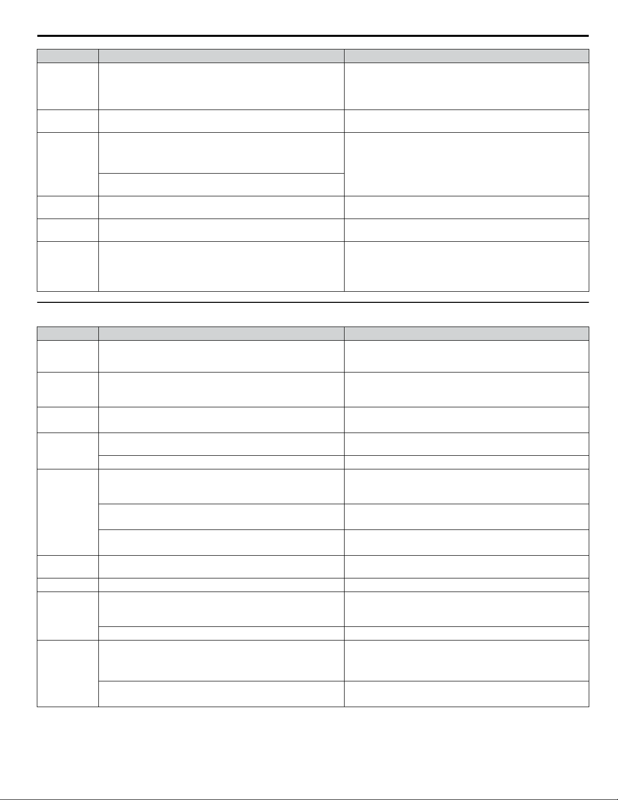
i.8 Troubleshooting
HOA Keypad Cause Possible Solution
The following simultaneous contradictory settings have occurred:
oPE09
oPE10
oPE11
oPE16
oPE27
oPE28
u
Auto-Tuning Errors
• b5-15 is not set to 0.0 (PID Sleep Function Operation Level)
• The stopping method is set to either DC Injection Braking or coast
to stop with a timer (b1-03 = 2 or 3).
V/f pattern setting error.
E1-09 ≤ E1-07 < E1-06 ≤ E1-11 ≤ E1-04
The following simultaneous contradictory settings have occurred:
C6-05 > 6 and C6-04 > C6-03 (carrier frequency lower limit is
greater than the upper limit).
If C6-05 ≤ 6, the drive operates at C6-03.
The upper and lower limits between C6-02 and C6-05 are
contradictory.
The following contradictory settings are true:
A1-02 = 0, S1-01 =1, and b8-01 = 1
If digital inputs A4, A5, or A7 or digital outputs A4 or A5 are
programmed, then all must be programmed
• S2-01 > S2-02
• S2-06 > S2-07
• S2-11 > S2-12
• S2-16 > S2-17
• Set b5-15 to a value other than 0.0.
• Set the stopping method to coast to stop or ramp to stop
(b1-03 = 0 or 1).
Correct the settings for E1-04, E1-06, E1-07, E1-09, and E1-11.
Correct the parameter settings.
Correct the parameter settings.
Correct the parameter settings.
Correct the parameter settings.
HOA Keypad Cause Possible Solution
End3
End4
End5
End7
Er-01
Er-02
Er-03 Auto-Tuning canceled by pressing STOP button. Auto-Tuning did not complete properly. Restart Auto-Tuning.
Er-04
Er-05
Er-08
Rated current alarm
The correct current rating printed on the motor nameplate was not
entered into T1-04.
Adjusted Slip Calculation Error
The calculated slip is outside the allowable range.
Resistance Tuning Error
The calculated slip is outside the allowable range.
No-Load Current Alarm
The entered no-load current value was outside the allowable range.
Auto-Tuning results were less than 5% of the motor rated current. Double-check the data entered for the Auto-Tuning process.
Motor data error
Motor data or data entered during Auto-Tuning was incorrect.
Motor output power and motor-rated current settings (T1-02 and
T1-04) do not match.
Motor rated current and detected no-load current are inconsistent.
Minor Fault
An alarm was triggered during Auto-Tuning.
Line-to-Line Resistance Error
Motor data entered during Auto-Tuning was incorrect.
Faulty motor cable or cable connection. Check and correct faulty motor wiring.
No-Load Current Error/Rated Slip Error
Motor data entered during Auto-Tuning was incorrect.
Results from Auto-Tuning are outside the parameter setting range
or the tuning process took too long.
Results from Auto-Tuning are outside the parameter setting range
or the tuning process took too long.
• Check the setting of parameter T1-04.
• Check the motor data and repeat Auto-Tuning.
• Make sure the data entered for Auto-Tuning is correct.
• If possible, perform Rotational Auto-Tuning. If not possible,
perform Stationary Auto-Tuning 2.
• Double-check the data entered for the Auto-Tuning process.
• Check the motor and motor cable connection for faults.
Check and correct faulty motor wiring.
• Check that the motor data entered to T1 parameters matches
motor nameplate input before Auto-Tuning.
• Restart Auto-Tuning and enter the correct information.
• Check the drive and motor capacities.
• Correct the settings of parameters T1-02 and T1-04.
• Check the motor rated current and no-load current.
• Correct the settings of parameters T1-04 and E2-03.
Exit the Auto-Tuning menu, check the alarm code, remove the
alarm cause, and repeat Auto-Tuning.
• Make sure the data entered to the T1 parameters match the
information written on the motor nameplate.
• Restart Auto-Tuning and enter the correct information.
• Make sure the data entered to the T1 parameters match the
information written on the motor nameplate.
• Restart Auto-Tuning and enter the correct information.
• Check and correct faulty motor wiring.
• Perform Rotational Auto-Tuning.
YASKAWA ELECTRIC TOEP YAIZ1U 02A YASKAWA AC Drive – Z1000 Safety Precautions
51
Page 52

F2F1
ESC
M M
AUTO OFF
ENTERRESET
-DRIVE-
U1- 01=60.00Hz
----------------
U1- 02=60.00Hz
JOG FWD FWD/REV
-Rdy-
ALM
DIGITAL OPERATOR JVOP-183
HAND
Freq Ref (OPR)
i.8 Troubleshooting
HOA Keypad Cause Possible Solution
Acceleration Error
The motor did not accelerate for the specified acceleration time.
Er-09
The load was too high during Rotational Auto-Tuning.
• Increase the acceleration time (C1-01).
• Disconnect the machine from the motor if possible.
• Disconnect the motor from machine and restart Auto-Tuning. If
motor and load cannot be uncoupled make sure the load is lower
than 30%.
• If a mechanical brake is installed, make sure it is fully lifted
during tuning.
Current Detection Error
One of the motor phases is missing: (U/T1, V/T2, W/T3).
Check motor wiring and correct any problems.
The current exceeded the current rating of the drive. • Check motor wiring for a short between motor lines.
Er-12
The current is too low.
• Close any magnetic contactors used between motors.
• Replace the control board or the entire drive. For instructions on
replacing the control board, contact Yaskawa or your nearest
sales representative.
u
Fault Reset Methods
When a fault occurs, the cause of the fault must be removed and the drive must be restarted. The table below lists the different
ways to restart the drive.
After the Fault Occurs Procedure
Fix the cause of the fault, restart the drive, and
reset the fault
Resetting via Fault Reset Digital Input S4
Press on the HOA keypad.
Close then open the fault signal digital input via
terminal S4. S4 is set for “Fault Reset” as default
(H1-04 = 14).
Fault Reset Switch
2
Drive
S4 Fault Reset Digital Input
SC Digital Input Common
ON
Turn off the main power supply if the above methods do not reset the fault. Reapply power after the
HOA keypad display has turned off.
When an “SC” error occurs, contact Yaskawa or a Yaskawa agent before cycling the power to the drive.
1
OFF
Note: If the Run command is present, the drive will disregard any attempts to reset the fault. Remove the Run command before attempting to clear
a fault situation.
52
YASKAWA ELECTRIC TOEP YAIZ1U 02A YASKAWA AC Drive – Z1000 Safety Precautions
Page 53

i.9 UL and CSA Standards
i.9 UL and CSA Standards
u
UL Standards Compliance
The UL/cUL mark applies to products in the United States and Canada. It indicates that UL has performed product testing and
evaluation, and determined that their stringent standards for product safety have been met. For a product to receive UL
certification, all components inside that product must also receive UL certification.
Figure i.16 UL/cUL Mark
This drive is tested in accordance with UL standard UL508C and complies with UL requirements. The conditions described
below must be met to maintain compliance when using this drive in combination with other equipment:
Installation Area
n
Do not install the drive to an area greater than pollution degree 2 (UL standard).
Ambient Temperature
n
IP20/NEMA Type 1 Enclosure: -10 to +40 °C
IP00 Open Type Enclosure: -10 to +50 °C
Main Circuit Terminal Wiring
n
Wire Gauges and Tightening Torques
Refer to Main Circuit Wire Gauges and Tightening Torque on page 19 for details.
Closed-Loop Crimp Terminal Recommendations
Yaskawa recommends using closed-loop crimp terminals on all drive models. To maintain UL/cUL approval, UL Listed
closed-loop crimp terminals are specifically required when wiring the drive main circuit terminals on models 5A0041 to
5A0242. Use only the tools recommended by the terminal manufacturer for crimping. Refer to Closed-Loop Crimp Terminal
Recommendations on page 23 for closed-loop crimp terminal recommendations.
Note:
The mark indicates the terminals for protective ground connection as defined in IEC/EN 60417-5019.
Grounding impedance: 600 V: 10 Ω or less
.
Factory Recommended Branch Circuit Protection for UL Compliance
NOTICE: If a fuse is blown or a Ground Fault Circuit Interrupter (GFCI) is tripped, check the wiring and the selection of the peripheral devices.
Check the wiring and the selection of peripheral devices to identify the cause. Contact Yaskawa before restarting the drive or the peripheral
devices if the cause cannot be identified.
Yaskawa recommends installing one of the following types of branch circuit protection to maintain compliance with UL508C.
Semiconductor protective type fuses are preferred. Alternate branch circuit protection devices are also listed in Table i.20.
Table i.20 Factory Recommended Drive Branch Circuit Protection
Drive Model
5A0003 2 3.6 15 6.25 10 FWP-50B (50)
5A0004 3 5.1 15 8 15 FWP-50B (50)
5A0006 5 8.3 15 12 20 FWP-60B (60)
5A0009 7.5 12 20 20 35 FWP-60B (60)
5A0011 10 16 30 25 45 FWP-70B (70)
Nominal
Output Power
HP
AC Drive Input
Amps
MCCB Rating
Amps
<1>
600 V Class
Time Delay Fuse
Rating Amps
Non-time Delay
<2>
Fuse Rating
Amps
<3>
Bussmann Semi-
conductor Fuse
Rating (Fuse
Ampere)
<4>
YASKAWA ELECTRIC TOEP YAIZ1U 02A YASKAWA AC Drive – Z1000 Safety Precautions
53
Page 54

i.9 UL and CSA Standards
Drive Model
5A0017 15 23 40 40 60 FWP-100B (100)
5A0022 20 31 60 50 90 FWP-100B (100)
5A0027 25 38 75 60 110 FWP-125A (125)
5A0032 30 45 75 75 125 FWP-125A (125)
5A0041 40 44 75 75 125 FWP-175A (175)
5A0052 50 54 100 90 150 FWP-175A (175)
5A0062 60 66 125 110 175 FWP-250A (250)
5A0077 75 80 150 125 225 FWP-250A (250)
5A0099 100 108 175 175 300 FWP-250A (250)
5A0125 125 129 225 225 350 FWP-350A (350)
5A0145 150 158 300 275 450 FWP-350A (350)
5A0192 200 228 400 350 600 FWP-600A (600)
5A0242 250 263 500 450 700 FWP-600A (600)
<1> Maximum MCCB Rating is 15 A, or 200 % of drive input current rating, whichever is larger. MCCB voltage rating must be 600 VAC or greater.
<2> Maximum Time Delay fuse is 175% of drive input current rating. This covers any Class CC, J or T class fuse.
<3> Maximum Non-time Delay fuse is 300% of drive input current rating. This covers any CC, J or T class fuse.
<4> When using semiconductor fuses, Bussman FWP are required for UL compliance.
<5> Class L fuse is also approved for this rating.
Nominal
Output Power
HP
AC Drive Input
Amps
MCCB Rating
Amps
<1>
Time Delay Fuse
Rating Amps
Non-time Delay
Fuse Rating
<2>
Amps
<3>
Bussmann Semi-
conductor Fuse
Rating (Fuse
Ampere)
<4>
Low Voltage Wiring for Control Circuit Terminals
n
Wire low voltage wires with NEC Class 1 circuit conductors. Refer to national state or local codes for wiring. The external
power supply shall be a UL listed Class 2 power supply source or equivalent only. Refer to NEC Article 725 Class 1, Class
2, and Class 3 Remote-Control, Signaling, and Power Limited Circuits for requirements concerning class 1 circuit conductors
and class 2 power supplies.
Table i.21 Control Circuit Terminal Power Supply
Input / Output Terminal Signal Power Supply Specifications
Multi-function digital inputs S1, S2, S3, S4, S5, S6, S7, SC, SP, SN
Multi-function analog inputs +V, A1, A2, AC, FM, AM
Drive Short Circuit Rating
n
Use the internal control power supply of the drive or an
external class 2 power supply.
The drive is suitable for use on a circuit capable of delivering not more than 100,000 RMS symmetrical Amperes, 600 Vac
maximum (600 V Class) when protected by Bussmann Type FWH or FWP fuses as specified in Table i.20 Factory
Recommended Drive Branch Circuit Protection on page 53.
u
CSA Standards Compliance
54
Figure i.17 CSA Mark
YASKAWA ELECTRIC TOEP YAIZ1U 02A YASKAWA AC Drive – Z1000 Safety Precautions
Page 55

i.9 UL and CSA Standards
CSA for Industrial Control Equipment
n
The drive is CSA-certified as Industrial Control Equipment Class 3211.
Specifically, the drive is certified to: CAN/CSA C22.2 No. 04-04 and CAN/CSA C22.2 No.14-05.
u
Drive Motor Overload Protection
Set parameter E2-01 (motor rated current) to the appropriate value to enable motor overload protection. The internal motor
overload protection is UL listed and in accordance with the NEC and CEC.
E2-01: Motor Rated Current
n
Setting Range: Model-dependent
Default Setting: Model-dependent
Parameter E2-01 protects the motor when parameter L1-01 is not set to 0. The default for L1-01 is 1, which enables protection
for standard induction motors.
If Auto-Tuning has been performed successfully, the motor data entered to T1-04 is automatically written to parameter E2-01.
If Auto-Tuning has not been performed, manually enter the correct motor rated current to parameter E2-01.
L1-01: Motor Overload Protection Selection
n
The drive has an electronic overload protection function (oL1) based on time, output current, and output frequency that protects
the motor from overheating. The electronic thermal overload function is UL-recognized, so it does not require an external
thermal relay for single motor operation.
This parameter selects the motor overload curve used according to the type of motor applied.
Table i.22 Overload Protection Settings
Setting Description
0 Disabled Disabled the internal motor overload protection of the drive.
1 Standard fan-cooled motor (default)
2 Drive duty motor with a speed range of 1:10
3 Vector motor with a speed range of 1:100
Permanent Magnet motor with variable
4
torque
Permanent Magnet motor with constant
5
torque
6 Standard fan-cooled motor (50 Hz)
Selects protection characteristics for a standard self-cooled motor with limited cooling capabilities
when running below the rated speed. The motor overload detection level (oL1) is automatically
reduced when running below the motor rated speed.
Selects protection characteristics for a motor with self-cooling capability within a speed range of
10:1. The motor overload detection level (oL1) is automatically reduced when running below
1/10 of the motor rated speed.
Selects protection characteristics for a motor capable of cooling itself at any speed including zero
speed (externally cooled motor). The motor overload detection level (oL1) is constant over the
entire speed range.
Selects protection characteristics for a variable torque PM motor. The motor overload detection
level (oL1) is automatically reduced when running below the motor rated speed.
Selects protection characteristics for a constant torque PM motor. The motor overload detection
level (oL1) is constant over the whole speed range.
Selects protection characteristics for a standard self-cooled motor with limited cooling capabilities
when running below the rated speed. The motor overload detection level (oL1) is automatically
reduced when running below the motor rated speed.
When connecting the drive to more than one motor for simultaneous operation, disable the electronic overload protection
(L1-01 = 0) and wire each motor with its own motor thermal overload relay.
Enable motor overload protection (L1-01 = 1 to 6) when connecting the drive to a single motor, unless another motor overload
preventing device is installed. The drive electronic thermal overload function causes an oL1 fault, which shuts off the output
of the drive and prevents additional overheating of the motor. The motor temperature is continually calculated while the drive
is powered up.
YASKAWA ELECTRIC TOEP YAIZ1U 02A YASKAWA AC Drive – Z1000 Safety Precautions
55
Page 56

Operation time (minutes)
Cold start
(characteristics when an
overload occurs at a
complete stop)
Hot start
(characteristics when an
overload occurs during
continuous operation at 100%)
Motor current (%)
E2-01 = 100% motor current
10
7
3
1
0.4
0.1
0 100 150 200
i.9 UL and CSA Standards
L1-02: Motor Overload Protection Time
n
Setting Range: 0.1 to 5.0 min
Factory Default: 1.0 min
Parameter L1-02 determines how long the motor is allowed to operate before the oL1 fault occurs when the drive is running
a hot motor at 60 Hz and at 150% of the full load amp rating (E2-01) of the motor. Adjusting the value of L1-02 can shift the
set of oL1 curves up the y axis of the diagram below, but will not change the shape of the curves.
Figure i.18 Motor Overload Protection Time
u
Precautionary Notes on External Heatsink (IP00/Open Type Enclosure)
When using an external heatsink, UL compliance requires covering exposed capacitors in the main circuit to prevent injury
to surrounding personnel.
NOTICE
Refer to the Z1000 User Manual (600 V models) TOEPYAIZ1U03 on the CD-ROM packaged with the product for more
information regarding Precautionary Notes on External Heatsink and complete product instructions necessary for proper
installation, set-up, troubleshooting and maintenance. CD part number TOECC71061615.
56
YASKAWA ELECTRIC TOEP YAIZ1U 02A YASKAWA AC Drive – Z1000 Safety Precautions
Page 57

i.10 European Standards
i.10 European Standards
Figure i.19 CE Mark
The CE mark indicates compliance with European safety and environmental regulations. It is required for engaging in business
and commerce in Europe.
European standards include the Machinery Directive for machine manufacturers, the Low Voltage Directive for electronics
manufacturers, and the EMC guidelines for controlling noise.
This drive is in conformance with the Low Voltage Directive.
• Low Voltage Directive: 2006/95/EC
Devices used in combination with this drive must also be CE certified and display the CE mark. When using drives displaying
the CE mark in combination with other devices, it is ultimately the responsibility of the user to ensure compliance with CE
standards. After setting up the device, verify that conditions meet European standards.
u
CE Low Voltage Directive Compliance
This drive has been tested according to European standard IEC/EN 61800-5-1, and it fully complies with the Low Voltage
Directive.
To comply with the Low Voltage Directive, be sure to meet the following conditions when combining this drive with other
devices:
Area of Use
n
Do not use drives in areas with pollution higher than severity 2 and overvoltage category 3 in accordance with IEC/EN 664.
Factory Recommended Branch Circuit Protection
n
NOTICE
Refer to the Z1000 User Manual (600 V models) TOEPYAIZ1U03 on the CD-ROM No. TOECC71061615 packaged with
the product; Chapter- Standards Compliance, Section-European Standards , for more information on Factory
Recommended Branch Circuit Protection for CE Compliance.
Grounding
n
The drive is designed to be used in T-N (grounded neutral point) networks. If installing the drive in other types of grounded
systems, contact your Yaskawa representative for instructions.
Guarding Against Harmful Materials
n
When installing IP00/Open Type enclosure drives, use an enclosure that prevents foreign material from entering the drive
from above or below.
u
Drive Derating Data
Rated Current Depending on Carrier Frequency
n
Increasing the carrier frequency above 2 kHz will reduce the rated output current of the drive.
NOTICE
Refer to the Z1000 User Manual (600 V models) TOEPYAIZ1U03 – Drive Derating Data section to assist in model selection
and adjustment when the application requires changing the drive carrier frequency from factory defaults.
YASKAWA ELECTRIC TOEP YAIZ1U 02A YASKAWA AC Drive – Z1000 Safety Precautions
57
Page 58
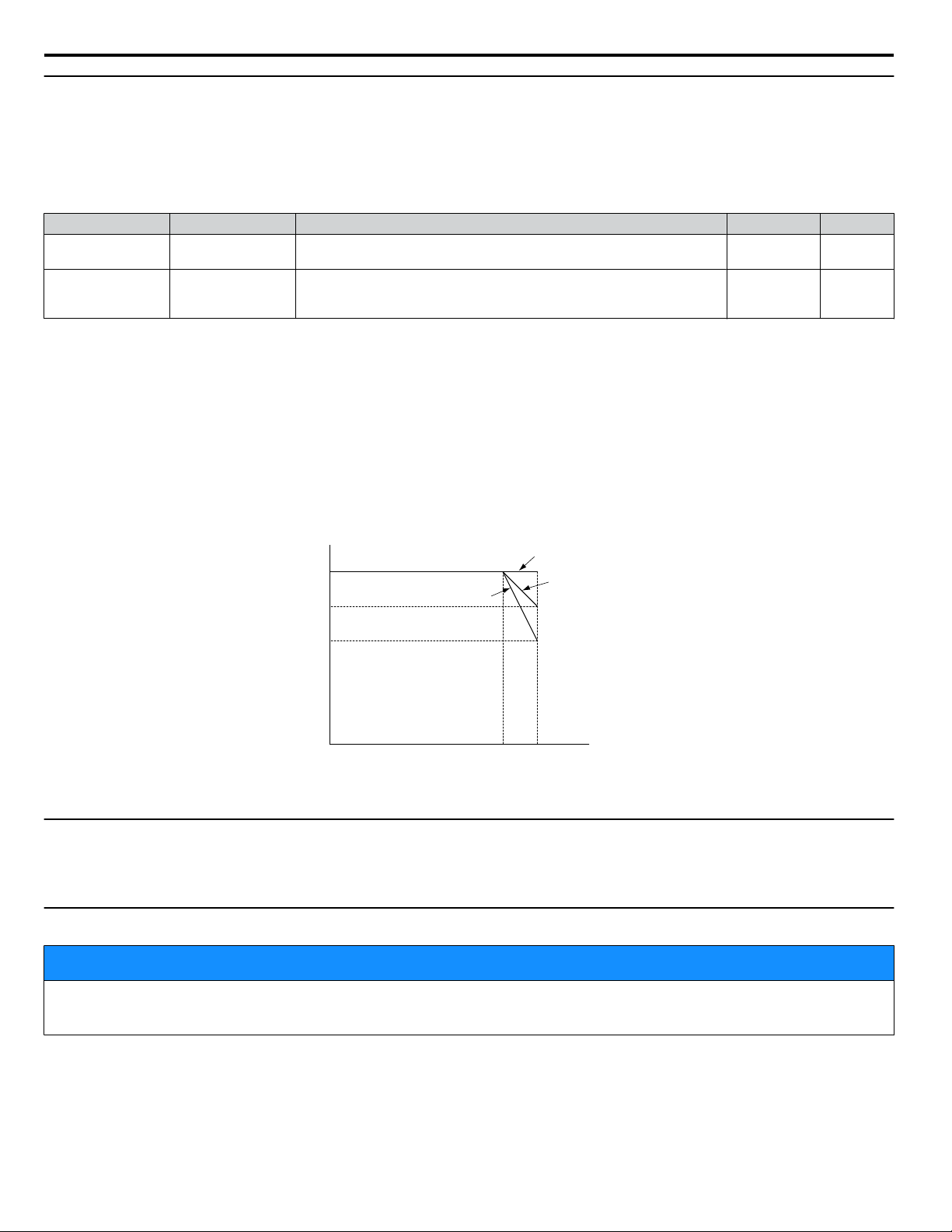
40°C
100%
60%
-10°C
0%
50°C
80%
IP20/NEMA Type 1
IP00/Open-Type
External Heatsink
i.10 European Standards
u
Temperature Derating
To ensure the maximum performance life, the drive output current must be derated as shown in Figure i.20 when the drive is
installed in areas with high ambient temperature or if drives are mounted side-by-side in a cabinet. In order to ensure reliable
drive overload protection, set parameters L8-12 and L8-35 according to the installation conditions.
Parameter Settings
n
No. Name Description Range Def.
L8-12
L8-35
Ambient
Temperature Setting
Installation Method
Selection
Adjust the drive overload (oL2) protection level when the drive is installed
in an environment that exceeds its ambient temperature rating.
0: IP00/Open-Chassis Enclosure
2: IP20/NEMA Type 1 Enclosure
3: External Heatsink Installation
40 to 60 30 °C
0, 2, 3 2
IP00/Open-Chassis Enclosure
Drive operation between -10 °C and +50 °C (14 and 122 °F) allows 100% continuous current without derating.
IP20/NEMA Type 1 Enclosure
Drive operation between -10 °C and +40 °C (14 and 104 °F) allows 100% continuous current without derating. Operation
between 40 °C and 50 °C (104 and 122 °F) requires output current derating.
Note: The temperature derating remains unchanged when removing the top protective cover and the bottom conduit bracket to change an IP20/
External Heatsink Installation
NEMA Type 1 enclosure drive to an IP00/Open-Type enclosure drive (derating required for temperatures over 40 °C [104 °F]).
Drive operation between -10 °C and +40 °C (14 and 104 °F) allows 100% continuous current without derating. Operation
between 40 °C and 50 °C (104 and 122 °F) requires output current derating.
Figure i.20 Ambient Temperature and Installation Method Derating
u
Altitude Derating
The drive standard ratings are valid for installation altitudes up to 1000 m. For installations from 1000 m to 3000 m, the drive
rated voltage and the rated output current must be derated for 0.2% per 100 m.
u
Dimensions, Weight, Heat Loss
NOTICE
Refer to the Mechanical Installation Chapter and the Specifications Chapter of the Z1000 User Manual (600 V models)
TOEPYAIZ1U03 which can be found on the CD-ROM packaged with the product.
58
YASKAWA ELECTRIC TOEP YAIZ1U 02A YASKAWA AC Drive – Z1000 Safety Precautions
Page 59

u
Drive Specifications
Item Specification
Control Method
Frequency Control Range 0.01 to 240 Hz
Frequency Accuracy
(Temperature Fluctuation)
Frequency Setting
Resolution
Output Frequency
Resolution
Frequency Setting Signal
Control
Character-
istics
Starting Torque
Speed Control Range
Speed Response
Accel/Decel Time 0.0 to 6000.0 s (4 selectable combinations of independent acceleration and deceleration settings)
Braking Torque Approximately 20%
V/f Characteristics User-selected programs and V/f preset patterns possible
Main Control Functions
<1>
<1>
i.10 European Standards
The following control methods can be set using drive parameters:
• V/f Control (V/f)
• Open Loop Vector Control for PM (OLV/PM)
Digital input: within ±0.01% of the max output frequency (-10 to +50 °C [14 to 122 °F])
Analog input: within ±0.1% of the max output frequency (25 °C ±10 °C [77 ±50°F])
Digital inputs: 0.01 Hz
Analog inputs: 1/1000 of the maximum output frequency setting (10 bit unsigned)
0.001 Hz
DC 0 to +10 V (20 kΩ), 4 to 20 mA (250 Ω)
0 to 20 mA (250 Ω)
V/f: 140% at 3 Hz
OLV/PM: 50% at 6 Hz
V/f: 1:40
<1>
OLV/PM: 1:20
OLV/PM: 10 Hz
Momentary Power Loss Ride-Thru, Speed Search, Overtorque/Undertorque Detection, 4 Step Speed
(max), Accel/Decel Switch, S-curve Accel/decel, 3-Wire Sequence, Auto-Tuning (Stationary for Line-toLine Resistance, Rotational for V/f Control), Cooling Fan on/off Switch, Slip Compensation, Torque
Compensation, Frequency Jump, Upper/lower Limits for Frequency Reference, DC Injection Braking at
Start and Stop, Overexcitation Braking, High Slip Braking, PI Control (with sleep function), Energy Saving
Control, APOGEE FLN Comm. (RS-422/RS-485 4.8 kbps), BACnet Comm. (RS-485 max. 76.8 kbps),
MEMOBUS/Modbus Comm. (RS-422/RS-485 max, 115.2 kbps), Metasys N2 Comm. (RS-422/RS-485
9.6 kbps), Fault Restart, Application Presets, KEB, Overexcitation Deceleration, Overvoltage Suppression,
Sequence Timer Operation, Secondary PI Control, Bypass Operation, HOA Keypad, Dynamic Noise
Control
YASKAWA ELECTRIC TOEP YAIZ1U 02A YASKAWA AC Drive – Z1000 Safety Precautions
59
Page 60

i.10 European Standards
Item Specification
Motor Protection Electronic thermal overload relay
Momentary Overcurrent
Protection
Overload Protection
Overvoltage Protection 600 V class: Stops when DC bus voltage exceeds approx. 1040 V
Protection
Functions
Undervoltage Protection 600 V class: Stops when DC bus voltage falls below approx. 475 V
Momentary Power Loss
Ride-Thru
Heatsink Overheat
Protection
Stall Prevention Stall Prevention is available during acceleration, deceleration, and during run.
Ground Protection
DC Bus Charge LED Remains lit until DC bus voltage falls below 50 V
Area of Use Indoors
Ambient Temperature
Humidity 95% RH or less (no condensation)
Environment
Storage Temperature -20 °C to +70 °C (-4 to +158 °F) (short-term temperature during transportation)
Altitude
Vibration/Shock
Standards
Protection Design
<1> The accuracy of these values depends on motor characteristics, ambient conditions, and drive settings. Specifications may vary with different motors
and with changing motor temperature. Contact Yaskawa for consultation.
<2> Overload protection may be triggered when operating with 150% of the rated output current if the output frequency is less than 6 Hz.
<3> May be shorter due to load conditions and motor speed.
<4> Ground protection cannot be provided when the impedance of the ground fault path is too low, or when the drive is powered up while a ground
fault is present at the output.
<5> Removing the top protective cover or bottom conduit bracket from an IP20/NEMA Type 1 enclosure drive voids NEMA Type 1 protection while
maintaining IP20 conformity. This is applicable to models 5A0003 to 5A0242.
Drive stops when rated output current exceeds 175%
Drive stops after 60 s at 110% of rated output current
Drive stops after 0.5 s at 140% of rated output current
Immediately stop after 15 ms or longer power loss
<2>
<2>
<3>
Continuous operation during power loss shorter than 2 s by speed search function
Thermistor
Electronic circuit protection
<4>
-10 °C to +40 °C (14 to 104 °F) IP20/NEMA Type 1 Enclosure
-10 °C to +50 °C (14 to 122 °F) IP00/Open Type Enclosure
Up to 1000 meters without derating, up to 3000 m with output current and voltage derating. Refer to
Altitude Derating on page 58 for details.
10 to 20 Hz: 9.8 m/s
2
20 to 55 Hz: 5.9 m/s2 (5A0003 to 5A0099)
2.0 m/s2 (5A0125 to 5A0242)
• UL508C
• IEC/EN 61800-5-1
• CSA
IP00/Open Type enclosure, IP20/NEMA Type 1 enclosure
<5>
60
YASKAWA ELECTRIC TOEP YAIZ1U 02A YASKAWA AC Drive – Z1000 Safety Precautions
Page 61

i.10 European Standards
YASKAWA ELECTRIC TOEP YAIZ1U 02A YASKAWA AC Drive – Z1000 Safety Precautions
61
Page 62

MANUAL NO. TOEP YAIZ1U 02A
Published in U.S.A. February 2014 14-2
Date of publication
Date of original publication
i.11 Revision History
i.11 Revision History
The revision dates and the numbers of the revised manuals appear on the bottom of the back cover.
Date of Publication
Revision
Number
Section Revised Content
February 2014 – – First Edition. This manual supports drive software version PRG: 4800.
62
YASKAWA ELECTRIC TOEP YAIZ1U 02A YASKAWA AC Drive – Z1000 Safety Precautions
Page 63

Page 64

YASKAWA AC Drive Z1000
AC Drive for HVAC Fan and Pump
Safety Precautions
YASKAWA AMERICA, INC.
2121 Norman Drive South, Waukegan, IL 60085, U.S.A.
Phone: (800) YASKAWA (927-5292) or 1-847-887-7000 Fax: 1-847-887-7310
http://www.yaskawa.com
DRIVE CENTER (INVERTER PLANT)
2-13-1, Nishimiyaichi, Yukuhashi, Fukuoka, 824-8511, Japan
Phone: 81-930-25-3844 Fax: 81-930-25-4369
http://www.yaskawa.co.jp
YASKAWA ELECTRIC CORPORATION
New Pier Takeshiba South Tower, 1-16-1, Kaigan, Minatoku, Tokyo, 105-6891, Japan
Phone: 81-3-5402-4502 Fax: 81-3-5402-4580
http://www.yaskawa.co.jp
YASKAWA ELÉTRICO DO BRASIL LTDA.
Avenda Fagundes Filho, 620 Bairro Saude, São Paulo, SP04304-000, Brasil
Phone: 55-11-3585-1100
http://www.yaskawa.com.br
YASKAWA EUROPE GmbH
Hauptstrasse 185, 65760 Eschborn, Germany
Phone: 49-6196-569-300 Fax: 49-6196-569-398
http://www.yaskawa.eu.com
YASKAWA ELECTRIC UK LTD.
1 Hunt Hill Orchardton Woods, Cumbernauld, G68 9LF, United Kingdom
Phone: 44-1236-735000
http://www.yaskawa.co.uk
YASKAWA ELECTRIC KOREA CORPORATION
7F, Doore Bldg. 24, Yeoido-dong, Yeoungdungpo-gu, Seoul, 150-877, Korea
Phone: 82-2-784-7844
http://www.yaskawa.co.kr
YASKAWA ELECTRIC (SINGAPORE) PTE. LTD.
151 Lorong Chuan, #04-01, New Tech Park, 556741, Singapore
Phone: 65-6282-3003
http://www.yaskawa.com.sg
YASKAWA ELECTRIC (SHANGHAI) CO., LTD.
No. 18 Xizang Zhong Road, 17F, Harbour Ring Plaza, Shanghai, 200001, China
Phone: 86-21-5385-2200
http://www.yaskawa.com.cn
YASKAWA ELECTRIC (SHANGHAI) CO., LTD. BEIJING OFFICE
Room 1011, Tower W3 Oriental Plaza, No. 1 East Chang An Ave.,
Dong Cheng District, Beijing, 100738, China
Phone: 86-10-8518-4086
YASKAWA ELECTRIC TAIWAN CORPORATION
9F, 16, Nanking E. Rd., Sec. 3, Taipei, 104, Taiwan
Phone: 886-2-2502-5003
Fax: 55-11-5581-8795
Fax: 44-1236-458182
Fax: 82-2-784-8495
Fax: 65-6289-3003
Fax: 86-21-5385-3299
Fax: 86-10-8518-4082
Fax: 886-2-2505-1280
YASKAWA AMERICA, INC.
In the event that the end user of this product is to be the military and said product is to be employed in any weapons systems or the manufacture
thereof, the export will fall under t he relevant regulations as stipulated in the Foreign Exchange and Foreign Trade Regulations. Therefore, be sure
to follow all proc edures and submit all relevant documentation according to any and all rules, regulations and laws that may apply.
Specifications are subject to change without notice for ongoing product modifications and improvement s.
© 2014 YASKAWA AMERI CA, INC. All rights reserved.
MANUAL NO. TOEP YAIZ1U 02A
Published in U.S.A. February 2014 14-2
 Loading...