

Page 1

YASKAWA
FOR VARISPEED-600 SERIES INVERTER
BRAKING UNIT
BRAKING RESISTOR UNIT
INSTRUCTIONS
MODEL: BRAKING UNIT CDBR-
BRAKING RESISTOR UNIT LKEB-
Upon receipt of the product and prior to initial operation, read these instructions
thoroughly, and retain for future reference.
YA S K A W A
MANUAL NO. TOE-C726-2F
Page 2

PREFACE
Braking resistor unit and braking unit are used to consume regenerative energy from motor in the braking
resistor unitat deceleration andto improve the transistor inverter braking ability.
Before using the braking resistor unit and braking unit,
a thorough understanding of this manual is recom-
mended. This instruction manual will be of great help
for daily maintenance, inspection and troubleshoot-
ing.
Inverters to which the braking resistorunit and braking
unit can be connected are of the following series:
- VS−616 Series
- VS−676 Series
- VS−866 Series
3
Page 3

General Precautions
: Some drawings in this manual are shownwith the protectivecover or shields
removed, in order to describe with more clarity. Make sure all covers and
shields are replaced before operating this product.
: Since the drawings in this manual are represented examples, some are sub-
ject to differ from delivered products.
: This manual may be modified when necessary because of improvement of
the product, modification or changes in specifications. Such modifications
are denoted by a revised manual No.
: To order a copy of this manual, if your copy has been damaged or lost, con-
tact your YASKAWA representative.
: YASKAWAis not responsible for any modification of the product made by
the user since that will void your guarantee.
4
Page 4
NOTES FOR SAFE OPERATION
Read this instruction manual thoroughly before installation, operation,
maintenance or inspection of the braking unit and the braking resistor unit. In this
manual, NOTES FOR SAFE OPERATION are classified as “WARNING” or
“CAUTION.”
WARNING
Indicates a potentially hazardous situation which, if not avoided, could result in
death or serious injury to personnel.
CAUTION
Indicates a potentially hazardous situation which, if not avoided, may result in minor or moderate injury to personnel and damage to equipment.
It may also be used to alert against unsafe practices.
Even items described in
situations. In either case, follow these important notes.
: These are steps to be taken to insure proper operation.
NOTE
CAUTION
may result in a vital accident in some
5
Page 5

RECEIVING
CAUTION
: Do not install or operate any braking unit or braking resistor
unit which is damaged or has missing parts.
Failure to observe this caution may result in personal injury or
equipment damage.
INSTALLATION
CAUTION
: Lift the cabinet bythe base. When moving the unit, never lift
by the front cover.
Otherwise, the main unit may be dropped causing damage to the
unit.
(Ref. page)
15
(Ref. page)
16
: Mount the braking unit and braking resistor unit on nonflam-
mable material (i.e. metal).
Failure to observe this caution can result in a fire.
: When mounting multiple units in an enclosure, install a fan or
other cooling device to keep the intake air temperature below 40EC.
Overheating may cause a fire or damage to the unit.
6
16
16
Page 6

WIRING
WARNING
: Only commence wiring after verifying that the power supply
is turned OFF.
Failure to observe this warning can result in an electrical shock or a
fire.
(Ref. page)
27
: High voltage exists at all terminals of braking unit and brak-
ing resistor unit.
Failure to observe this warning can result in an electrical shock.
: Wiring should be performed only by qualified personnel.
Failure to observe this warning can result in an electrical shock or a
fire.
: When wiring the emergency stop circuit, check the wiring
thoroughly before operation.
Failure to observe this warning can result in personal injury.
: Make sure to ground the ground terminal .
(Ground resistance
200V class: 100W or less, 400V class: 10W or less)
Failure to observe this warning can result in an electrical shock.
27
27
27
27
7
Page 7

CAUTION
: Verifythat the ratedvoltage of the braking unit and the brak-
ing resistor unit coincides with the AC power supply voltage.
Failure to observe this caution can result in personal injury or a fire.
(Ref. page)
27
: Do not perform a withstand voltage test of the braking unit
and braking resistor unit.
It may cause semi−conductor elements to be damaged.
: Connect braking resistors, braking resistor units, and brak-
ing units as shown in the I/O wiring examples. Use properly
rated wire in accordance with table 2 on page 31.
Otherwise, a fire can occur.
: Tighten terminal screws to the specified tightening torque.
Failure to observe this caution can result in a fire.
27
27
27
8
Page 8

OPERATION
WARNING
: Only turnON the input power supply afterreplacing the front
cover. Do not remove the cover while current is flowing.
Failure to observe this warning can result in an electrical shock.
CAUTION
: Never touch the heatsink or discharging resistor since the
temperature is very high.
Failure to observe this caution can result in harmful burns to the
body.
(Ref. page)
41
(Ref. page)
41
: Do not check signals during operation.
The machine or the inverter may be damaged.
: All the constants of the the braking unitand the brakingresis-
tor unit have been preset at the factory. Do not change the
settings unnecessarily.
9
41
41
Page 9

MAINTENANCE AND INSPECTION
WARNING
: Never touch high−voltage terminals in the the braking unit
and braking resistor unit.
Failure to observe this warning can result in an electrical shock.
(Ref. page)
46
: Replace all protective covers before powering up the brak-
ing unit and the braking resistor unit. To remove the cover,
make sure to shut OFF the molded −case circuit breaker.
Failure to observe this warning can result in an electrical shock.
: Perform maintenance or inspection only after verifying that
the CHARGE LED goes OFF, after the main circuit power
supply is turned OFF.
The capacitors are still charged and can be dangerous.
: Only authorized personnel should be permitted to perform
maintenance, inspections or parts replacement.
[Remove all metal objects (watches, bracelets, etc.) before
operation.]
(Use tools which are insulated against electrical shock.)
Failure to observe this warning can result in an electrical shock.
46
46
46
10
Page 10
CAUTION
: The control PC board employs CMOS ICs. Do not touch the
CMOS elements.
They are easily damaged by static electricity.
(Ref. page)
46
: Do not connect or disconnect wires or connectors while
power is applied to the circuit.
Failure to observe this caution can result in personal injury.
OTHERS
WARNING
: Never modify the product.
Failure to observe this warning can result in an electrical shock or
personal injury and will invalidate the guarantee.
46
11
Page 11
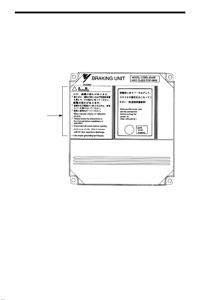
WARNING INDICATION
A warning label is displayed on the front cover of the braking unit, as shown below.
Follow these instructions when handling the braking unit and the braking resistor
unit .
Warning
Indication
Example of Braking Unit Model CDBR−4045B
12
Page 12

Warning Indication
May cause injury or electric shock.
⋅⋅⋅⋅ Please follow the instructions in the manual before
installation or operation.
⋅⋅⋅⋅ Disconnect all power before opening front cover of
unit. Wait 3 minutes until DC Bus capacitors
discharge.
⋅⋅⋅⋅ Use proper grounding techniques.
13
Page 13

CONTENTS
NOTES FOR SAFE OPERATION 5.........................
1. RECEIVING 15.......................................
2. INSTALLATION 16....................................
2.1 LOCATION 16.......................................
2.2 INSTALLATION 16...................................
2.3 REPLACEMENT OF CONVENTIONAL BRAKING UNITS
WITH NEW UNITS 25................................
3. WIRING 27..........................................
3.1 REMOVING AND REPLACING THE COVERS OF THE
BRAKING UNIT (MODELS CDBR−2015B, −2022B,
−4030B, −4045B) 27..................................
3.2 SECTION NAMES 28.................................
3.3 CIRCUITS AND WIRING SPECIFICATIONS 31..........
3.4 WIRING PRECAUTIONS 32...........................
3.5 INTERCONNECTION 33..............................
4. OPERATION 41......................................
4.1 ADJUSTMENT 41....................................
4.2 POWER SUPPLY VOLTAGE SELECTION CONNECTOR
SETTING 41........................................
4.3 MASTER/SLAVE SELECTION CONNECTOR SETTING 44
4.4 PARALLEL CONNECTION OF BRAKING UNIT 44.......
4.5 OPERATION 45......................................
5. TROUBLESHOOTING 46..............................
6. SPECIFICATIONS 47..................................
6.1 BRAKING UNIT AND BRAKING RESISTOR UNIT
APPLICATION LIST 47...............................
6.2 BRAKING UNIT FOR 575V CLASS APPLICATION LIST 49
6.3 LIST OF APPLICABLE/NOT APPLICABLE
COMBINATIONS WITH CONVENTIONAL
MODELS (VS−616HII/H3, VS−616GII/G3, VS−676) 50....
6.4 BRAKING UNIT SPECIFICATIONS 51..................
6.5 BRAKING RESISTOR UNIT SPECIFICATIONS 52........
14
Page 14

1. RECEIVING
1. RECEIVING
The braking resistor unit and braking unit have been put through severe tests at the
factory before shipment. After unpacking, however, check and see the following.
If any malfunctions are found, contact your YASKAWA representative.
: Their nameplate data meet your requirements.
: They have sustained no damage while in transit.
: Fastening bolts and screws are not loose.
15
Page 15

2. INSTALLATION
2.1 LOCATION
If the units are temporarily stored or machine stops for an extended length of time,
the following precautions should be taken. Store the units under the following conditions.
: Free from rainfall and drops of water.
: Clean and dry.
: Free from corrosive gases and liquids.
: Free from dirt and dust.
: Ambient temperature: 14 to 104EF, −10 to 4 0EC.
: Humidity: 90% RH or less (no condensation)
: Free from vibration.
2.2 INSTALLATION
For full use of the braking resistor unit or braking unit functions, install the units
in a location to satisfy the following conditions:
Figs. 1 to 8 show the external dimensions and the spaces from the periphery.
: Provide the spaces shown in Figs. 1 to 8 between the units and the periph-
ery.
: Since the braking resistor unit generates heat, provide sufficient spaces
from devices which are weak against heat.
: Install the units at such locations that all requirements described in Par.
2.1 “LOCATION” are satisfied.
: Install the units in the directions shown in Figs. 1 to 8. There will be n o
problem if they are installed vertically.
16
Page 16
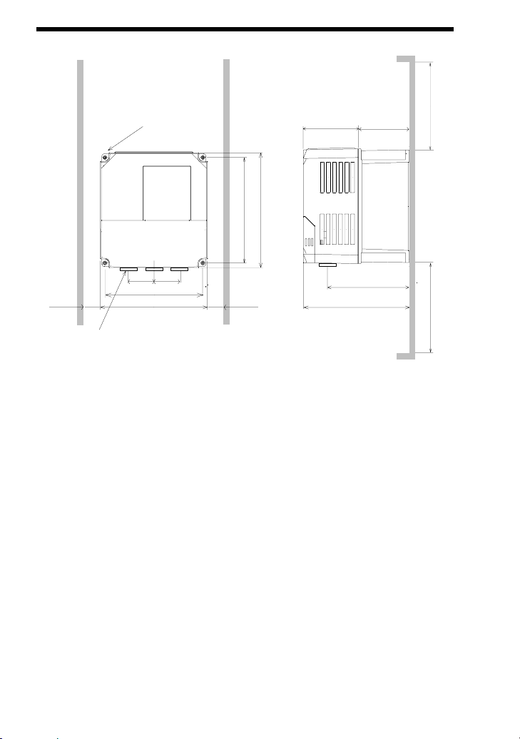
2. INSTALLATION
1.18 (30)
OR MORE
4−M4 MTG HOLE
1.5 (38)
1.5 (38)
5.04 (128)
5.51 (140)
5.43 (138)
5.91 (150)
1.18 (30)
OR MORE
2.83 (72)
2.73 (66.5)
4.51 (114.5)
5.45 (138.5)
3−LEAD WIRE OUTLET
[0.87 (20) DIA RUBBER BUSH]
Fig. 1 Braking Unit Dimensions in inches (mm) CDBR−2015B, −2022B,−4030B,
−4045B
3.94 (100) OR MORE
3.94 (100) OR MORE
17
Page 17

0.39 (10)
1.14 (29)
3.94 (100)
4−M6
MTG HOLE
3.94 (100)
OR MORE
2.19 (55.5)
MAIN CIRCUIT
TERMINAL M4
1.97 (50)
3.94 (100)
5.51 (140)
1.18 (30)
OR MORE
2.30
(58.5)
6.57 (167)
11.02 (280)
10.23 (260)
9.25 (235)
1.18 (30)
OR MORE
Fig. 2 Braking Unit Dimensions in inches (mm) CDBR−5037B
3−LEAD WIRE
OUTLET
1.10 (28) DIA
RUBBER BUSH
3.94 (100)
OR MORE
18
Page 18

2. INSTALLATION
4−M6
MTG HOLE
3.86 (98)
4.37 (111)
6.14 (156)
7.87 (200)
14.57 (370)
0.47 (12)
13.78 (350)
1.44 (36.5)
12.48 (317)
3.94 (100)
2.95 (75)
2.32
(59)
1.18 (30)
OR MORE
5.51 (140)
MAIN CIRCUIT
TERMINAL M5
1.97 (50)
5.51 (140)
7.09 (180)
1.18 (30)
OR MORE
Fig. 3 Braking Unit Dimensions in inches (mm) CDBR−2045B
3.94 (100)
OR MORE
WIRE OUTLET 1.10 (28)
DIA RUBBER BUSH
2−LEAD WIRE OUTLET
1.38 (35) DIA RUBBER
BUSH
3.94 (100)
OR MORE
19
Page 19

0.47 (12)
1.44 (36.5)
5.51 (140)
4−M6
MTG HOLE
3.94 (100)
OR MORE
MAIN CIRCUIT
14.57 (370)
13.78 (350)
12.48 (317)
3.94 (100)
2.87 (73)
2.32
(59)
1.18 (30)
OR MORE
TERMINAL M6
1.97 (50)
5.51 (140)
7.09 (180)
1.18 (30)
OR MORE
4.37 (111)
6.14 (156)
7.87 (200)
4.09
(104)
Fig. 4 Braking Unit Dimensions in inches (mm) CDBR−2110B
WIRE OUTLET 1.10 (28)
DIA RUBBER BUSH
2−LEAD WIRE OUTLET
1.38 (35) DIA RUBBER
BUSH
3.94 (100)
OR MORE
20
Page 20

2. INSTALLATION
4−M6
MTG HOLE
4.37 (111)
6.14 (156)
7.87 (200)
3.86 (98)
3.94 (100)
OR MORE
WIRE OUTLET 1.10 (28)
DIA RUBBER BUSH
2−LEAD WIRE OUTLET
1.38 (35) DIA RUBBER
BUSH
3.94 (100)
OR MORE
14.57 (370)
0.35 (9)
13.98 (355)
1.44 (36.5)
12.48 (317)
5.45 (138.5)
2.95 (75)
2.70
(68.5)
1.18 (30)
OR MORE
7.09 (180)
MAIN CIRCUIT
TERMINAL M5
1.97 (50)
7.09 (180)
8.66 (220)
1.18 (30)
OR MORE
Fig. 5 Braking Unit Dimensions in inches (mm) CDBR−4090B, −5110B
21
Page 21

1.44 (36.5)
8.27 (210)
0.35 (9)
4−M6
MTG HOLE
3.94 (100)
OR MORE
14.57 (370)
13.98 (355)
12.48 (317)
6.16 (156.5)
2.76 (70)
4.67 (118.5)
1.18 (30)
OR MORE
MAIN CIRCUIT
TERMINAL M6
1.97 (50)
8.27 (210)
9.84 (250)
1.18 (30)
OR MORE
4.37 (111)
6.14 (156)
7.87 (200)
4.09
(104)
WIRE OUTLET 1.10 (28)
DIA RUBBER BUSH
2−LEAD WIRE OUTLET
1.38 (35) DIA RUBBER
BUSH
3.94 (100)
OR MORE
Fig. 6 Braking Unit Dimensions in inches (mm) CDBR−4220B, −5300B
22
Page 22

2. INSTALLATION
UnitModel
Braking Resistor
(LKEB−P)
A B C D E
Dimensions in inches (mm)
20P7 4.13 (105) 10.83 (275) 1.97 (50) 10.24 (260) M5
21P5 5.12 (130) 13.78 (350) 2.95 (75) 13.19 (335) M5
22P2 5.12 (130) 13.78 (350) 2.95 (75) 13.19 (335) M5
23P7 5.12 (130) 13.78 (350) 2.95 (75) 13.19 (335) M5
25P5 9.84 (250) 13.78 (350) 7.87 (200) 13.19 (335) M6
27P5 9.84 (250) 13.78 (350) 7.87 (200) 13.19 (335) M6
40P7 4.13 (105) 10.83 (275) 1.97 (50) 10.24 (260) M5
41P5 5.12 (130) 13.78 (350) 2.95 (75) 13.19 (335) M5
42P2 5.12 (130) 13.78 (350) 2.95 (75) 13.19 (335) M5
43P7 5.12 (130) 13.78 (350) 2.95 (75) 13.19 (335) M5
45P5 9.84 (250) 13.78 (350) 7.87 (200) 13.19 (335) M6
47P5 9.84 (250) 13.78 (350) 7.87 (200) 13.19 (335) M6
Fig. 7 Braking Resistor Unit Dimensions in inches (mm) [for 0.5 to 10HP (0.4 to
7.5kW)]
23
Page 23

Braking Resistor
UnitModel
(LKEB−P)
2011 10.48 (266) 21.38 (543) 9.69 (246) 13.39 (340) M8
2015 14.02 (356) 21.38 (543) 13.23 (336) 13.39 (340) M8
2018 17.56 (446) 21.38 (543) 16.77 (426) 13.39 (340) M8
2022 17.56 (446) 21.38 (543) 16.77 (426) 13.39 (340) M8
4011 13.78 (350) 16.22 (412) 12.99 (330) 12.80 (325) M6
4015 13.78 (350) 16.22 (412) 12.99 (330) 12.80 (325) M6
4018 17.56 (446) 21.38 (543) 16.77 (426) 13.39 (340) M8
4022 17.56 (446) 21.38 (543) 16.77 (426) 13.39 (340) M8
4030 14.02 (356) 37.64 (956) 13.23 (336) 29.13 (740) M8
4037 17.56 (446) 37.64 (956) 16.77 (426) 29.13 (740) M8
4045 17.56 (446) 37.64 (956) 16.77 (426) 29.13 (740) M8
Fig. 8 Braking Resistor Unit Dimensions in inches (mm) [for 15 to 60HP (11 to
45kW)]
A B C D E
Dimensions in inches (mm)
24
Page 24

2. INSTALLATION
2.3 REPLACEMENT OF CONVENTI ONAL BRAKING UNITS WITH NEW UNITS
Toreplace conventional braking units (models CDBR−2015,−2022,−4030,−4045)
with new units (CDBR−2015B, −2022B, −4030B, −4045B), an exclusive−use at-
tachment is required. Contact your YASKAWA representative.
4−M6 MTG HOLE
0.79
(20)
0.79
(20)
ATTACHMENT
0.28(7)
3.94 (100)
4.13 (105)
11.02 (280)
10.24 (260)
5.91 (150)
0.98
(25)
3.94 (100)
5.51 (140)
0.28(7)
0.39
(10)
5.45 (138.5)
0.39 (10)
Code No.: DACT32732−AD
Fig. 9 Mounting Dimensions of Attachment in inches (mm)
25
Page 25

The main circuit terminal symbols are different between conventional models and
new models. Refer to the following table.
Table 1 Main Circuit Terminal Symbols
Conventional Models
N
P
P
0
B
New Models
©
¨
¨
0
©
0
26
Page 26
3. WIRING
3. WIRING
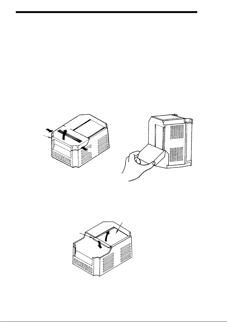
3.1 REMOVING AND REPLACING THE COVERS OF THE
BRAKING UNIT (MODELS CDBR−2015B, −2022B,
−4030B, −4045B)
(1) Removing and Replacing the Terminal Cover
For removing, grasp the terminal cover at (1) on both sides and then lift in the
direction of (2). For replacing, reverse the method.
Terminal
Cover
(1)
(1)
(2)
(2)
(1)
(1)
(2) Removing and Replacing the Indicating Cover
Remove the terminal cover first. Push down on the lever in the direction of
(1) and lift the cover in the direction of (2). For replacing, reverse the method.
Indicating Cover
Lever
(2)
(1)
27
Page 27

3.2 SECTION NAMES
Figs. 10, 11 and 12 show appearance and each section name of braking unit and
braking resistor unit respectively.
Thermal overload relay protects the braking resistor unit for models LKEB−20P7
to −27P5, and thermal protector protects the braking resistor unit for models
LKEB−2011 to −2022 and −4018 to −4045.
BRAKING UNIT
MODEL:CDBR−2015B
200V CLASS FOR 15kW
Power Supply Selection
Connector
Master/Slave
Selection Connector
May cause injury or electric
shock.
Please followthe instructions in
the manualbefore installation or
operation.
Disconnect allpower before opening
front cover ofunit. Wait 3 minutes
until DCBus capacitors discharge.
Use proper grounding techniques.
Calibration Resistor
(Adjusted Prior to
Shipment)
Operation Indicator
(Lights when Discharging.)
©¨¨
©
0
0
1256
Control Circuit
Terminals 1 to 6
Charge Indicator
(Charge Lamp)
Control Circuit Terminals
Lead Wire Outlet
(3 Places: Rubber Bush)
©¨¨
0©0
Fig. 10 Braking Resistor Unit Model CDBR−2015B (Terminal Cover and
Indicationg Cover Removed)
28
Page 28

Thermal Overload Relay
(Automatically Reset)
3. WIRING
Lead Wire Outlet
(Rubber Bush)
Control Circuit Terminals
B, P, 1, 2
Fig. 11 Braking Resistor Unit Model LKEB−20P7 (Front Cover Removed)
29
Page 29

Resistor
Thermal
Overload
Protector
Lead Wire Outlet
(Rubber Bush)
Fig. 12 Braking Resistor Unit Model LKEB−2022 (Front Cover Removed)
Control Circuit Terminals
B, P, 1, 2
30
Page 30

3.3 CIRCUITS AND WIRING SPECIFICATIONS
(
13.3
(
(Model
CDBR
600V
l
q
(
equivalent
Table 2 Circuits and Wiring Specifications
Wire
0
0
0
0
0
0
Size
AWG
2
(mm
12−10
(3.5−5.5)
18−14
(0.75−2)
10−8
(5.5−8)
18−14
(0.75−2)
4 (22)
8−6
(8−14)
18−14
(0.75−2)
12−10
(3.5−5.5)
18−14
(0.75−2)
)
*1
Wire Type
600V
(High
*3
Voltage)
viny
sheathed
wire or
uivalent
e
Terminal
Screw
M4
M5
M4
M6
M4
M4
(M5)
M4 15.6 (1.76)
Name
Braking Unit
(Models CDBR
−2015B, −2022B,
−4030B, −4045B,
−5037B)
Braking Unit
Model CDBR
−2045B, −4090B,
−5110B)
Braking Unit
(Model
CDBR−2110B,
−4220B,−5300B)
Braking Resistor
Unit
(Model LKEB−
j)
Con-
trol
Con-
trol
Con-
trol
Termi-
nals
¨¨
©©
123
456
¨¨
©©
123
456
¨¨
©©
123
456
Circuit
Main
Main
Main
Main BP
Con-
trol
12
*1 For wire size of 8−6(8−14), use UL1283 heat−resistant vinyl−insulated wire or
equivalent.
*2 M4 for Models LKEB−20P7 to −27P5 or −40P7 to −4015.
M5 for Models LKEB−2011 to −2022 or −4018 to −4045.
*3 Models−5037B, −5100B, and −5300B can reach an operating voltage of 1040 VDC.
Please select wire which is suitable for the operating voltage.
*2
(21.7(2.45))
Torque
(N⋅m)
15.6 (1.76)
Max.
lb⋅in
13.3
(1.50)
21.7
(2.45)
15.6
(1.76)
43.4
(4.90)
15.6
(1.76)
31
Page 31

3.4 WIRING PRECAUTIONS
(1) Wiring Leading−in Method
Lead in the wire through the knockout hole on the unit bottom. Since the
knockout hole is provided with a rubber bush, cut the rubber bush central
crosswise with a blade and lead the wire through.
(2) Separation from Signal Lines
Since strong noise component is superimposed on the braking resistor unit
and braking unit wiring, separate the units from signal lines which are weak
against noise.
(3) Wiring Distance
Wiring distance between the braking resistor unit and braking unit or braking
unit and inverter must be provided as shown in Fig. 13. Make sure to bundle
the wires between the units.
Braking Resistor
Unit
Fig. 13 Wiring Distance
Braking Unit
32.8ft
(10m)
or less
Inverter
16.4ft
(5m)
or less
32
Page 32

3. WIRING
(4) Grounding Method
: Mount the braking resistor unit on a grounded metallic plate. When it can-
not be mounted on a grounded metallic plate, pull out the lead wire from
the mounting screw section to ground.
:
Braking unit grounding terminal must be provided with class 3 ground
(ground resistance: 100Ω or less.)
: Use the sizes specified in “INTERNAL CONNECTION SPECIFI-
CATIONS” for grounding cables.
3.5 INTERCONNECTION
Figs. 14 to 20 show the interconnecting diagrams of the braking unit or braking resistor unit and VS−616G5.
Refer to Par.3.3, “Wiring Precautions” for proper wiring in actual wiring design and
work.
Be sure to connect braking resistors or braking resistor units to the braking units.
Connect only braking resistors or Braking Resistor Units (LKEB−XXXX) to Brak-
ing Units.
NOTE
If using another braking resistor instead of YASKAWA braking resistor unit, be sure to protect by thermal overload relay.
33
Page 33

,
4
∗
IM
Motor
400V Class : 10Ω or less)
Ground (200V Class : 100Ω or less
Overload Relay Trip Contact
Use sequencer to break
power supply side on over-
load relay trip contact of
Braking Resistor Unit
1 2
3
∗
DC Reactor
braking resistor unit.
BP
(Option)
Short−circuit
Bar
B2
B1
©
¨ 2
¨ 1
MC
MCCB
3−Phase
U (T1)
L1 (R)
R
Power Supply
200 to 230 V
V (T2)
L2 (S)
S
50/60 Hzor380 to 460 V
W (T3)
L3 (T)
T
2
∗
VS−616G5
400/200 V
50/60 Hz
MC
ON
OFF
THRX
MC
SA
Overload Relay Trip Contact
∼
THRX
of Braking Resistor Unit
∼
∼
∼
∗1 Where ∗ is ”E” or “V”.
SA
TRX
MC
12
∗2 The transformer is not necessary for 200V class.
SA
(provided as standard) and connect a DC reactor with the terminals.
∗3 When installing a DC reactor (option), remove the common bar between ¨1 and ¨2 terminals
TRX
20 18
decel is disabled). If it is not changed, the inverter may not stop within set decel time.
∗4 When using the braking resistor unit, set constant L3−04 to “0” (stall prevention selection during
Fault
Contact
Models CIMR−G5∗40P4 to −G5∗4015 (400 V Class 0.4 to 15 kW)
Fig. 14 For Models CIMR−G5∗20P4 to −G5∗27P5 (200 V Class 0.55 to 7.5 kW)
34
Page 34

¨
P
0
¨
Use sequencer to break
power supply side on over-
3. WIRING
3
∗
Braking Resistor Unit
2
B
0
©
Braking Unit
1
Level
Detection
©
Overload Relay Trip Contact
4
3
Motor
U (T1)©V (T2)
IM
W (T3)
Ground (200V Class : 100Ω or less
400V Class : 10Ω or less)
∼
∼
VS−616G5
2
∗
L1 (R)
L2 (S)
L3 (T)
∼
∼
MC
SA
THRX
MC
ON
Overload Relay Trip Contact
of Braking Resistor Unit
2
1
R
S
OFF
T
THRX
(provided as standard) and connect a DC reactor with the terminals.
decel is disabled). If it is not changed, the inverter may not stop within set decel time.
20 18
Fault
Fig. 15 For Models CIMR−G5∗2011 to −G5∗2015 (200 V Class 11, 15 kW)
Contact
∗1 Where ∗ is “E” or ”V”.
∗2 When installing a DC reactor (option), remove the common bar between ¨1 and ¨2 terminals
∗3 When using the braking resistor unit, set constant L3−04 to “0” (stall prevention selection during
SA
SA
MC
TRX
TRX
Short−circuit
Bar
¨ 1 ¨ 2 ¨ 3
MC
MCCB
DC Reactor
(Option)
load relay trip contact of
braking resistor unit.
Power Supply
3−Phase
200 to 230 V
50/60 Hz
35
Page 35

2
∗
Braking Resistor
Unit (Option)
2
P
B
1
Level
Detection
Overload Relay Trip Contact
34
©
Short−circuit Bar
(Provided as
Standard)
0
0
©
¨
¨
Braking Unit
IM
Motor
U (T1)
V (T2)
L1 (R)
W (T3)
Cooling Fan
M
)
1
L2 (S)
L3 (T)
r(ç
©
¨ 1 ¨ 2 ¨ 3
MC
)
2
(ç
400V Class : 10Ω or less)
Ground (200V Class : 100Ω or less
VS−616G5
∼
∼
∼
∼
∗1 Where ∗ is “E” or “V”.
decel is disabled). If it is not changed, the inverter may not stop within set decel time.
∗2 When using the braking resistor unit, set constant L3−04 to “0” (stall prevention selection during
Fig. 16 For Models CIMR−G5∗2018 to−G5∗2022 (200 V Class 18.5, 22 kW)
Use sequencer to break
power supply side on over-
SA
MCCB
load relay trip contact of
braking resistor unit.
R
S
Power Supply
200 to 230 V
3−Phase
MC
MC
ON
T
THRX OFF
50/60 Hz
Overload Relay Trip Contact
of Braking Resistor Unit
SA
THRX
12
MC
TRX
SA
TRX
Fault
Contact
20 18
36
Page 36

3. WIRING
2
∗
Braking Resistor
Unit (Option)
P
B
1 2
Level
Detection
Overload Relay Trip Contact
4
3
©
0
0
©
¨
¨
Braking Unit
IM
Motor
U (T1)
V (T2)
©
W (T3)
Cooling Fan
M
Ground (200V Class : 100Ω or less
400V Class : 10Ω or less)
∼
∼
VS−616G5
)
)
1
2
Voltage
Selection
460/440/415/
400/380V
(ç
L3 (T)
r(ç
∼
∼
∗1 Where ∗ is ”E“ or “V”.
decel is disabled). If it is not changed, the inverter may not stop within set decel time.
∗2 When using the braking resistor unit, set constant L3−04 to “0” (stall prevention selection during
Fig. 17 For Models CIMR−G5∗4018 to −G5∗4045 (400 V Class 18.5 to 45 kW)
Short−circuit Bar
(Provided as
Standard)
L1 (R)
L2 (S)
¨ 1 ¨ 2 ¨ 3
MC
Use sequencer to break
power supply side on over-
load relay trip contact of
braking resistor unit.
MCCB
R
Power Supply
3−Phase
MC
SA
400/200V
MC
ON
OFF
T
S
THRX
380 to 460 V
50/60 Hz
Overload Relay Trip Contact
of Braking Resistor Unit
SA
THRX
12
MC
TRX
SA
TRX
Fault
Contact
20 18
37
Page 37

2
∗
Braking Resistor
Unit (Option)
250VAC, 1A or less
©
¨ 3
30VDC, 1A or less)
MC
MCCB
U (T1)
VS−616G5
L1 (R)
R
Motor
IM
V (T2)
L2 (S)
S
W (T3)
L3 (T)
T
)
1
r(ç
Cooling Fan
M
Voltage
Selection
400
MC
400/200V
ON
THRX
400)
2
(ç
460/440/415/
400/380V
SA
MC
OFF
400V Class : 10Ω or less)
Ground (200V Class : 100Ω or less
Overload Relay Trip Contact
of Braking Resistor Unit
∼
∼
THRX
∼
∼
SA
TRX
2
MC
1
∗1 Where ∗ is ”E” or “V”.
∗2 When using the braking resistor unit, set constant L3−04 to
SA
If it is not changed, the inverter may not stop within set decel time.
“0” (stall prevention selection during decel is disabled).
TRX
20 18
Fault
Fig. 18 For Models CIMR−G5∗4055 to −G5∗4160 (400 V Class 55 to 160 kW)
Contact
P
B
1 2
0
©
0
¨
Level
Use sequencer to break
power supply side on over-
load relay trip contact of
Detection
Braking Unit
braking resistor unit.
¨
Overload Relay Trip Contact
©
230VAC, 1A or less)
(Thermal Protector Contact:
4
3
Cooling Fin Overheat Contact
(Thermoswitch Contact:
Power Supply
3−Phase
38
380 to 460 V
50/60 Hz
Page 38

P
0
¨
¨
2
∗
Braking Resistor
Unit (Option)
B
0
©
Braking Unit
2
1
Level
Detection
©
Overload Relay Trip Contact
(Thermal Protector Contact:
4
3
230VAC, 1A or less)
Cooling Fin Overheat Contact
(Thermoswitch Contact:
©
250VAC, 1A or less
30VDC, 1A or less)
U (T1)
Motor
IM
V (T2)
W (T3)
Ground (200V Class : 100Ω or less
400V Class : 10Ω or less)
∼
∼
3. WIRING
Use sequencer to break
power supply side on over-
VS−616G5
¨ 3
L1 (R)
MC
MCCB
load relay trip contact of
braking resistor unit.
R
Power Supply
3−Phase
Cooling Fan
M
)
)
1
2
(ç
L3 (T)
L2 (S)
r(ç
∼
∼
∗1 Where ∗ is “E” or “V”.
“0” (stall prevention selection during decel is disabled).
∗2 When using the braking resistor unit, set constant L3−04 to
If it is not changed, the inverter may not stop within set decel time.
Fig. 19 For Models CIMR−G5∗2030 to −G5∗2075 (200 V Class 30 to 75 kW)
MC
SA
SA
SA
TRX
MC
TRX
20 18
Fault
Contact
THRX
ON
MC
OFF
T
S
THRX
200 to 230 V
50/60 Hz
Overload Relay Trip Contact
of Braking Resistor Unit
12
39
Page 39

P
0
¨
2
∗
Braking Resistor
Unit (Option)
B
0
©
12
230VAC, 1A or less)
Overload Relay Trip Contact
(Thermal Protector Contact:
Motor
IM
400V Class : 10Ω or less)
Use sequencer to break
power supply side on over-
M
Voltage
Selection
Ground (200V Class : 100Ω or less
400)
2
(ç
460/440/415/
400
400/380V
∼
∼
∗1 Where ∗ is “E” or ”V”.
“0” (stall prevention selection during decel is disabled).
∗2 When using the braking resistor unit, set constant L3−04 to
If it is not changed, the inverter may not stop within set decel time.
∼
∼
Level
Detection
34
Braking Unit
©
Cooling Fin Overheat Contact
(Thermoswitch Contact:
©
¨ 3
¨ 1
250VAC, 1A or less
30VDC, 1A or less)
U (T1)
L1 (R)
V (T2)
W (T3)
VS−616G5
L3 (T)
L2 (S)
)
1
r(ç
Cooling Fan
¨
Fig. 20 For Models CIMR−G5∗4185 to −G5∗4220 (400 V Class 185 to 220 kW)
MC
MC
SA
load relay trip contact of
braking resistor unit.
MCCB
400/200V
MC
ON
OFF
R
T
S
THRX
Overload Relay Trip Contact
of Braking Resistor Unit
THRX
SA
SA
TRX
TRX
2
MC
1
Fault
18
20
Contact
Power Supply
3−Phase
40
380 to 460 V
50/60 Hz
Page 40

4. OPERATION
4. OPERATION
4.1 ADJUSTMENT
The braking resistor unit and braking unit do not have to be adjusted.
Especially, do not readjust the braking unit except in the case described in Par. 4.2,
“Power Supply Voltage Selection Connector Setting.”
4.2 POWER SUPPLY VOLTAGE SELECTION CONNECTOR SETTING
It may be necessary to select power supply voltage selection connector for braking
unit according to main circuit power supply type. Table 3 shows the relationship
between the power supply voltage selection connector and braking start voltage.
The following is the setting prior to shipment:
: 200V class: 220V
: 400V class: 440V
: 575V class: 575V
For removing the terminal cover and the indicating cover, refer to Par. 3.1.
41
Page 41

1
2
MODEL:CDBR−2015B
200V CLASS FOR 15kW
56
BRAKING UNIT
May cause injury or electric
shock.
Please followthe instructions in
the manualbefore installation or
operation.
Disconnect allpower befo reopening
front cover ofunit. Wait 3 minutes
until DCBus capacitors discharge.
Use proper grounding techniques.
¨©
¨
0
©
0
Fig. 21 Braking Unit Power Supply Voltage Selection
(Models CDBR−2015B, −2022B, −4030B, −4045B, Terminal Cover and
Indicating Cover Removed)
200V
00V
4
class
200V
208V
220V
230V
class
380V
400V
415V
440V
460V
42
Page 42

4. OPERATION
200V
class
400V
class
380V
575V
200V
208V
220V
230V
class
400V
415V
440V
460V
500V
575V
Fig. 22 Braking Unit Power Supply Voltage Selection
(Models CDBR−2045B, −2110B, −4090B, −5037B, −5110B, −5300B,
Indicating Cover Removed)
Table 3 Power Supply Voltage Selection Connector and Braking Start Voltage
200V
Class*
Power
Supply
Voltage
230V
Braking Start
Voltage
(PN Bus−bar
Voltage)
380V (TYP) 460V 760V (TYP) 575V 950V (TYP)
400V
Class*
Power
Supply
Voltage
Braking Start
Voltage
(PN Bus−bar
Voltage)
575V
Class*
Power
Supply
Voltage
Braking Start
Voltage
(PN Bus−bar
Voltage)
220V 365V (TYP) 440V 730V (TYP) − −
208V 345V (TYP) 415V 690V (TYP) − −
200V 330V (TYP) 400V 660V (TYP) 500V 825V (TYP)
− − 380V 630V (TYP) − −
*Allowable voltage fluctuation is ¦10%
43
Page 43

4.3 MASTER/SLAVE SELECTION CONNECTOR SETTING
Selection Connector Setting MASTER side is selected prior to shipment. Use the
units without changing the setting.
SLAVE side is selected when more than one braking unit is combined to use and
braking start levels must coincide. Refer to Par. 4.4, “Parallel Connection of Braking Unit” for details.
4.4 PARALLEL CONNECTION OF BRAKING UNIT
For using more than one parallel−connected braking unit, connect and select the
connectors as follows. (See Fig. 23.)
:
Braking units have a MASTER/SLAVE selection connector. (See Fig.
10.) Select MASTER side only for braking unit 1 and select SLAVE side
for braking units 2 and 3.
:
Connect thermal protector on the braking resistor unit and thermoswitch
on the braking unit in parallel. Refer to Figs. 15 and 18 for proper wiring.
: Use properly rated wire in accordance with table 2 on page 31.
: Use twisted−pair wires of 1mm or less for connection between 5, 6 and
1, 2 of the braking units.
:
Parallel connection of braking unit is possible up to a maximum of 10
units.
44
Page 44

4. OPERATION
Braking Resistor
Overheat Contact
(Thermal Relay Trip Contact)
12
©
¨
MASTER
SLAVE
Braking Unit 3
1
2
Cooling Fin
Overheat Contact
(Thermoswitch Contact)
Braking
Resistor
Unit
B
P
¨
©
0
0
5
6
¨ 3
Inverter
Unit
©
©
1
2
Braking Unit 1
Braking Resistor
Overheat Contact
(Thermal Relay Trip Contact)
12
Braking
Resistor
Unit
B
P
¨
¨
©
0
0
MASTER
Level
Detection
SLAVE
+15
5
6
4
3
Cooling Fin
Overheat Contact
(Thermoswitch Contact)
Braking Resistor
Overheat Contact
(Thermal Relay Trip Contact)
©
¨
MASTER
SLAVE
1
Braking Unit 2
P
2
Cooling Fin
Overheat Contact
(Thermoswitch Contact)
12
Braking
Resistor
Unit
B
P
¨
©
0
0
5
P
6
4343
Fig. 23 Example of Parallel Connection of Three Braking Units
4.5 OPERATION
Check that required deceleration characteristics can be obtained. While the braking
unit is operating, BRAKE lamp lights for easy check of operation.
NOTE
High voltage is applied to the braking unit. At normal operation, do
not operate the unit without cover.
45
Page 45

5. TROUBLESHOOTING
Braking
resistor
p
Inverter
trips
at
overvoltage
(OV).
byheatsink
Only authorized personnel should be permitted to perform maintenance and inspections or replace parts.
No. Fault Status Cause Corrective Action
unit overload
relay (or thermal
1
overload protector) trips when not
decelerating.
Inverter tripsat
2
overvoltage (OV).
Braking resistor
unit overload
relay (or thermal
3
protector) sometimes trips.
Braking unittrips
4
heat.
: Without braking unit
Inverter built−in main circuit discharging transistor short circuited
: With braking unit
Braking unit main circuit discharging
transistor short circuited
Improper braking unit power supply
voltage selection connector setting
(Power supply voltage > power supply voltage selection position)
Insufficient braking resistor unit capacity
Improper wiring Check and repair.
Braking unit fault Replace the unit.
Insufficient braking resistor unit capacity
Excessive start/stop switching frequency
Excessive load inertia
-
over-
Improper combination of braking
unit and braking resistor unit
Ambient temperature 104EF (40EC) Reduce it.
Replace the inverter.
Replace the unit.
Set it again.
Examine the braking
conditions again.
Examine the braking
conditions again.
Examine the operating conditions again.
Reset.
46
Page 46

6. SPECIFICATIONS
Braking
6. SPECIFICATIONS
6.1 BRAKING UNIT AND BRAKING RESISTOR UNIT APPLICATION LIST
200 to 230V
Unit
Q’ty
Approx.
Torque
(10%ED)
%
Inverter Braking Unit Braking Resistor Unit
Max Applicable
Motor Capacity
HP(kW)
0.5 (0.4) — — 20P7 70W 200Ω 1 220
1 (0.75) — — 20P7 70W 200Ω 1 125
2 (1.5) — — 21P5 260W 100Ω 1 125
3 (2.2) — — 22P2 260W 70Ω 1 120
5 (3.7) — — 23P7 390W 40Ω 1 125
7.5 (5.5) — — 25P5 520W 30Ω 1 115
10 (7.5) — — 27P5 780W 20Ω 1 125
15 (11) 2015B 1 2011 2400W 13.6Ω 1 125
20 (15) 2015B 1 2015 3000W 10Ω 1 125
25 (18.5) 2022B 1 2018 4800W 8Ω 1 125
30 (22) 2022B 1 2022 4800W 6.8Ω 1 125
40 (30) 2015B 2 2015 3000W 10Ω 2 125
50 (37) 2015B 2 2015 3000W 10Ω 2 100
60 (45) 2022B 2 2022 4800W 6.8Ω 2 120
75 (55) 2022B 2 2022 4800W 6.8Ω 2 100
100 (75) 2110B 1 2022 4800W 6.8Ω 3 110
120 (90) 2110B 1 2022 4800W 6.8Ω 4 120
150 (110) 2110B 1 2022 4800W 6.8Ω 5 100
Model
(CDBR
− P)
Unit
Q’ty
Model
(LKEB
− P)
Resistor Spec.
(per unit)
47
Page 47

380 to 460V
Braking
Inverter Braking Unit Braking Resistor Unit
Max Applicable
Motor Capacity
HP(kW)
0.5 (0.4) — — 40P7 70W 750Ω 1 230
1 (0.75) — — 40P7 70W 750Ω 1 130
2 (1.5) — — 41P5 260W 400Ω 1 125
3 (2.2) — — 42P2 260W 250Ω 1 135
5 (3.7) — — 43P7
7.5 (5.5) — — 45P5 520W 100Ω 1 135
10 (7.5) — — 47P5 780W 75Ω 1 130
15 (11) — — 4011 1040W 50Ω 1 135
20 (15) — — 4015 1560W 40Ω 1 125
25 (18.5) 4030B 1 4018
30 (22) 4030B 1 4022 4800W 27.2Ω 1 125
40 (30) 4030B 1 4030 6000W 20Ω 1 125
50 (37) 4045B 1 4037
60 (45) 4045B 1 4045 9600W 13.6Ω 1 125
75 (55) 4030B 2 4030 6000W 20Ω 2 135
100 (75) 4045B 2 4045 9600W 13.6Ω 2 145
150 (110) 4030B 3 4030 6000W 20Ω 3 100
200 (160) 4220B 1 4045 9600W 13.6Ω 4 140
300 (220) 4220B 1 4037 9600W 16Ω 5 110
400 (300) 4220B 2 4045 9600W 13.6Ω 6 110
800 (600) 4220B 4 4045 9600W 13.6Ω 12 110
Model
(CDBR
− P)
Unit
Q’ty
Model
(LKEB
− P)
Resistor Spec.
(per unit)
390W 150Ω
4800W 32Ω
9600W 16Ω
Unit
Q’ty
1 135
1 125
1 125
Approx.
Torque
(10%ED)
%
48
Page 48

6. SPECIFICATIONS
Braking
6.2 BRAKING UNIT FOR 575V CLASS APPLICATION LIST
Inverter Braking Unit Braking Resistor Unit
Max Applicable
Motor Capacity
HP(kW)
5 (3.7) — — 560W 150Ω 180
7.5 (5.5) — — 560W 150Ω 125
10 (7.5) — — 750W 100Ω 140
15 (11) — — 1100W 75Ω 125
20 (15) — — 1500W 50Ω 140
25 (18.5) — — 2300W 40Ω 140
30 (22) 5037B 1 2800W 38Ω 125
40 (30) 5037B 1 3900W 33Ω 110
50 (37) 5037B 1 4900W 27Ω 110
60 (45) 5037B 2 5900W 22Ω 110
75 (55) 5037B 2 7200W 18Ω 110
100 (75) 5110B 1 9800W 13.6Ω 105
120 (90) 5110B 1 12000W 11Ω 110
150 (110) 5110B 1 15000W 9Ω 110
200 (160) 5300B 1 21000W 6.8Ω 100
Model
(CDBR− P)
Unit Q’ty Resistor Spec.
Approx.
Torque
(10%ED)
%
49
Page 49

6.3 LIST OF APPLICABLE/NOT APPLICABLE COMBINA-
TIONS WITH CONVENTIONAL MODELS (VS−616HII/
H3, VS−616GII/G3, VS−676)
Conventional
Model
VS−616HII/H3
VS−616GII/G3
VS−676
VS−616HII/H3
VS−616GII/G3
VS−676
VS−616HII/H3
VS−616GII/G3
VS−676
VS−616HII/H3
VS−616GII/G3
VS−676
Braking
Unit
—
Model
CDBR−15H
etc.
Models
CDBR
−2015,
−2015B etc.
Models
CDBR
−2015,
−2015B etc.
Braking Re-
sistor Unit
Model
LKEB−20P7
etc.
Model
LKEB−2015
etc.
Model
LKEB−4.8K
etc.
Model
LKEB−2015
etc.
Applicable/
Not Appli-
cable
Applicable
Applicable
Not applicable
Applicable
Remarks
See connection examples of Fig 14.
Use sequencer to break
power supply side on
thermal protector of
the braking resistor
unit side.
No thermal protective
function of braking resistor unit.
See connection examples of Figs. 15 to 18.
50
Page 50

6.4 BRAKING UNIT SPECIFICATIONS
BrakingUnitModel
charac
Envi
Condi-
200V to 300V 380V to 460V 500V to 575V
CDBR−
Applicable Motor Output
HP (kW)
Max. Discharge
Current(A)
(peak value) *
Rated Discharge
Output
Current (A)
charac-
Braking Start
teristics
Voltage
Max. Hysteresis
Error
Power
VDC
Supply
Protec-
Fin Overheat Thermostat
tive
Power Charge
Func-
Indication
tions
Location Indoor (protected from corrosive gases and dust)
Altitude 1000m max.
Envion-
on-
Ambient
mental
Temperature
Conditions
Storage
Transportation
Temperature
Humidity 90%RH (non−condensing)
Vibration 1G at 10 to less than 20Hz, up to 0.2G at 20 to 50 Hz
Protective Configuration Wall−mountedenclosed type
Heat Loss (W)
2015B2022B2045B2110B4030B4045B4090B4220B5037B5110B5300
20
(15)30(22)60(45)
40 60 100 250 40 60 100 250 40 100 250
15 20 30 80 15 18 30 80 15 30 80
330/345/365/380V ¦3V
Approx. 8V Approx. 16V
243 (1.35¢200¢0.9) to
400V peak
32 38 31 64 54 59 35 71 22 53 116
150
40
(110)
(30)60(45)
630/660/690/730/760V
460 (1.35¢380¢0.9) to
800V peak
Charge lamp stays ON until bus voltage drops below 50V.
+14 to 104EF(−10 to +40EC) (not frozen)
−4 to 140EF(−20 to +60EC)
120
(90)
¦6V
6. SPECIFICATIONS
300
(220)
57
(37)
825V/ 950V ¦8V
(1.35¢500¢0.9) to
150
(110)
Approx.
20V
607
1000V
B
400
(300)
* Loading time rate can be used below 10% ED (max. 10 sec.)
51
Page 51

6.5 BRAKING RESISTOR UNIT SPECIFICATIONS
230V
(
)
380
Model
(LKEB
− P)
20P7 70W 200Ω 30 0.39
21P5 260W 100Ω 60 0.77
22P2 260W 70Ω 89 1.1
23P7
25P5
27P5
2011
2015 3000W 10Ω 600 7.7
2018 4800W 8Ω 740 9.6
2022 4800W 6.8Ω 880 11.4
40P7 70W 750Ω 30 0.20
41P5 260W 400Ω 60 0.39
42P2 260W 250Ω 89 0.60
43P7 390W 150Ω 150 1.0
45P5 520W 100Ω 220 1.5
47P5
4011
4015
4018 4800W 32Ω 740 4.8
4022 4800W 27.2Ω 880 5.7
4030 6000W 20Ω 1200 7.7
4037 9600W 16Ω 1500 9.7
4045 9600W 13.6Ω 1800 11.5
Specifications
390W 40Ω 150 1.9
200
520W 30Ω 220 2.7
to
780W 20Ω 300 3.9
2400W 13.6Ω 440 5.7
780W 75Ω 300 2.0
380
to
1040W 50Ω 440 3.0
460V
1560W 40Ω 600 3.9
Allowable
Average
Dissipated
Power
(W)
Allowable
Average
Current
(Effective Value)
(A)
Allowable
Ambient
Temperature
+14 to 122EF
−10 to +50EC
E
E
52
Page 52

6. SPECIFICATIONS
Model
CodeN
200
to
230V
380
to
575V
6.6 MODELS AND CODE NOS. OF BRAKING UNIT AND BRAKING RESISTOR UNIT
(1) Braking Unit
Inverter
Voltage HP (kW)
20 (15) CDBR−2015B 72600−R2150B
200 to
230V
380 to
460V
500 to
30 (22) CDBR−2022B 72600−R2220B
60 (45) CDBR−2045B 72600−R2450B
150 (110) CDBR−2110B 72600−R21100B
40 (30) CDBR−4030B 72600−R4300B
60 (45) CDBR−4045B 72600−R4450B
120 (90) CDBR−4090B 72600−R4900B
300 (220) CDBR−4220B 72600−R42200B
50 (37) CDBR−5037B 72600−R5370B
150 (110) CDBR−5110B 72600−R51100B
400 (300) CDBR−5300B 72600−R53000B
o.
53
Page 53

(2) Braking Resistor Unit
Resistor
Spec.
Model
CodeN
200
to
230V
460V
Inverter
Voltage HP(kW)
1 (0.75) 70W 200Ω LKEB−20P7 72600−K2P70
2 (1.5) 260W 100Ω LKEB−21P5 72600−K2010
3 (2.2) 260W 70Ω LKEB−22P2 72600−K2020
5 (3.7) 390W 40Ω LKEB−23P7 72600−K2030
200 to
230V
380 to
7.5 (5.5) 520W 30Ω LKEB−25P5 72600−K2050
10 (7.5) 780W 20Ω LKEB−27P5 72600−K2070
15 (11) 2400W 13.6Ω LKEB−2011 72600−K2110
20 (15) 3000W 10Ω LKEB−2015 72600−K2150
25 (18.5) 4800W 8Ω LKEB−2018 72600−K2180
30 (22) 4800W 6.8Ω LKEB−2022 72600−K2220
1 (0.75) 70W 750Ω LKEB−40P7 72600−K4P70
2 (1.5) 260W 400Ω LKEB−41P5 72600−K4010
3 (2.2) 260W 250Ω LKEB−42P2 72600−K4020
5 (3.7) 390W 150Ω LKEB−43P7 72600−K4030
7.5 (5.5) 520W 100Ω LKEB−45P5 72600−K4050
10 (7.5) 780W 75Ω LKEB−47P5 72600−K4070
15 (11) 1040W 50Ω LKEB−4011 72600−K4110
20 (15) 1560W 40Ω LKEB−4015 72600−K4150
25 (18.5) 4800W 32Ω LKEB−4018 72600−K4180
30 (22) 4800W 27.2Ω LKEB−4022 72600−K4220
40 (30) 6000W 20Ω LKEB−4030 72600−K4300
50 (37) 9600W 16Ω LKEB−4037 72600−K4370
60 (45) 9600W 13.6Ω LKEB−4045 72600−K4450
Resistor Spec.
(per unit)
o.
54
Page 54

FOR VARISPEED-600 SERIES INVERTER
BRAKING UNIT
BRAKING RESISTOR UNIT
INSTRUCTIONS
IRUMA BUSINESS CENTER
480, Kamifujisawa, Iruma, Saitama 358-8555, Japan
Phone 81-42-962-5696 Fax 81-42-962-6138
YASKAWA ELECTRIC AMERICA, INC.
2121 Norman Drive South, Waukegan, IL 60085, U.S.A.
Phone 1-847-887-7000 Fax 1-847-887-7370
MOTOMAN INC. HEADQUARTERS
805 Liberty Lane West Carrollton, OH 45449, U.S.A.
Phone 1-937-847-6200 Fax 1-937-847-6277
YASKAWA ELETRICO DO BRASIL COMERCIO LTD.A.
Avenida Fagundes Filho, 620 Bairro Saude-Sao Paulo-SP, Brazil CEP: 04304-000
Phone 55-11-5071-2552 Fax 55-11-5581-8795
YASKAWA ELECTRIC EUROPE GmbH
Am Kronberger Hang 2, 65824 Schwalbach, Germany
Phone 49-6196-569-300 Fax 49-6196-569-398
Motoman Robotics Europe AB
Box 504 S38525 Torsas, Sweden
Phone 46-486-48800 Fax 46-486-41410
Motoman Robotec GmbH
Kammerfeldstraβe 1, 85391 Allershausen, Germany
Phone 49-8166-90-100 Fax 49-8166-90-103
YASKAWA ELECTRIC UK LTD.
1 Hunt Hill Orchardton Woods Cumbernauld, G68 9LF, United Kingdom
Phone 44-1236-735000 Fax 44-1236-458182
YASKAWA ELECTRIC KOREA CORPORATION
Kfpa Bldg #1201, 35-4 Youido-dong, Yeongdungpo-Ku, Seoul 150-010, Korea
Phone 82-2-784-7844 Fax 82-2-784-8495
YASKAWA ELECTRIC (SINGAPORE) PTE. LTD.
151 Lorong Chuan, #04-01, New Tech Park Singapore 556741, Singapore
Phone 65-6282-3003 Fax 65-6289-3003
YASKAWA ELECTRIC (SHANGHAI) CO., LTD.
4F No.18 Aona Road, Waigaoqiao Free Trade Zone, Pudong New Area, Shanghai 200131, China
Phone 86-21-5866-3470 Fax 86-21-5866-3869
YATEC ENGINEERING CORPORATION
4F., No.49 Wu Kong 6 Rd, Wu-Ku Industrial Park, Taipei, Taiwan
Phone 886-2-2298-3676 Fax 886-2-2298-3677
YASKAWA ELECTRIC (HK) COMPANY LIMITED
Rm. 2909-10, Hong Kong Plaza, 186-191 Connaught Road West, Hong Kong
Phone 852-2803-2385 Fax 852-2547-5773
BEIJING OFFICE
Room No. 301 Office Building of Beijing International Club, 21
Jianguomenwai Avenue, Beijing 100020, China
Phone 86-10-6532-1850 Fax 86-10-6532-1851
TAIPEI OFFICE
9F, 16, Nanking E. Rd., Sec. 3, Taipei, Taiwan
Phone 886-2-2502-5003 Fax 886-2-2505-1280
SHANGHAI YASKAWA-TONGJI M & E CO., LTD.
27 Hui He Road Shanghai China 200437
Phone 86-21-6553-6060 Fax 86-21-5588-1190
BEIJING YASKAWA BEIKE AUTOMATION ENGINEERING CO., LTD.
30 Xue Yuan Road, Haidian, Beijing P.R. China Post Code: 100083
Phone 86-10-6233-2782 Fax 86-10-6232-1536
SHOUGANG MOTOMAN ROBOT CO., LTD.
7, Yongchang-North Street, Beijing Economic Technological Investment & Development Area,
Beijing 100076, P.R. China
Phone 86-10-6788-0551 Fax 86-10-6788-2878
YASKAWA ELECTRIC CORPORATION
YASKAWA
In the event that the end user of this product is to be the military and said product is to be
employed in any weapons systems or the manufacture thereof, the export will fall under
the relevant regulations as stipulated in the Foreign Exchange and Foreign Trade
Regulations. Therefore, be sure to follow all procedures and submit all relevant
documentation according to any and all rules, regulations and laws that may apply.
Specifications are subject to change without notice
for ongoing product modifications and improvements.
MANUAL NO. TOE-C726-2F
C
○ Printed in Japan August 2002 91-3
02-5①
24
 Loading...