

Page 1
DWG. NO. 02Y00025-0415
SHEET NO. 1 OF 5
REL. 10/28/96 (m-df)
For GPD 333
and GPD 5 03
Adjustable Frequency Drives
CHANGE RECORD
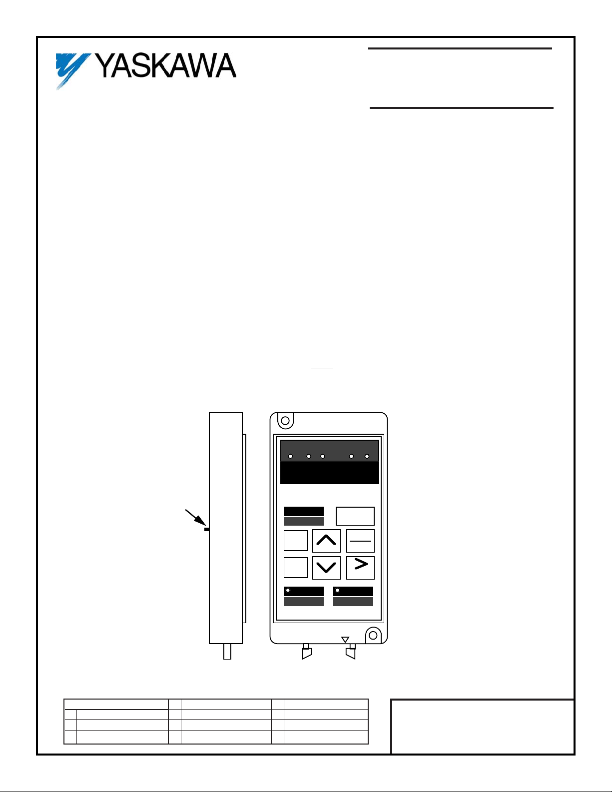
DATA
DISPLAY
JOG
COPY
MODE
RESET
F / R
VRFY
DRIVE
PRGM
SWITCH
ENTER
READ
RUN
COPY
STOP
REMOTE
COPY UNIT
JVOP-105
SEQ REF
DRIVE
FWD REV
COPY UNIT
MODEL NO. DS596
Before installing this option, a TECHNICALLY QUALIFIED INDIVIDUAL, who is familiar with this type of
equipment and hazards involved, should READ this ENTIRE INSTRUCTION SHEET.
INTRODUCTION
When installed, the Copy Unit (DS596) is used to read out constant settings from a drive and to copy them into
other drives easily from a remote location, up to 9.8 ft (3 m) from the drive. The Copy Unit is similar to Digital
Operator, Model No. DS393.
NOTE: Constants cannot be read from and copied to different types of drives.
EXAMPLE: GPD 333 ———> GPD 503.
IMPORTANT
The appropriate length Remote Operator Cable for connecting the Copy Unit, and the Remote
Interface Panel, Model DS390 (for the GPD 333), must be ordered separately.
Figure 1. Copy Unit
Page 2

DWG. NO. 02Y00025-0415
SHEET NO. 2 OF 5
REL. 10/28/96 (m-df)
Refer to Sheet 1 for latest change.
COPY UNIT SPECIFICATIONS
DRIVE TYPE ADDITIONAL ITEMS NEEDED FOR COPY UNIT INSTALLATION
GPD 333 Remote Interface Panel, Model No. DS090, + Remote Operator Cable
(1)
GPD 503 Remote Operator Cable
(1)
(1)
Remote Operator Cables available: 1 m cable - Model No. DS351; 3 m cable - Model No. DS353
•
• The exernal dimensions, LED display section and connections with the drive are the same as Digital Operator,
Model No. DS393.
•
• Backup power supply is not required, because EPROM is used as a data memory element.
•
• Number of writing times: Up to 100,000.
•
• Copy Unit has the same functions as Digital Operator, Model No. DS393.
•
• The Copy Unit is capable of storing three (3) different sets of constants.
•
• Prohibition of constant read out can be set by the switch located on the rear side of the Copy Unit.
CAUTION
1. Turn power off when you connect or remove the Copy Unit. If you remove the
connection cable during Copy Unit operation, the drive may not operate normally.
2. Constants cannot be read from/copied to different types of drives.
EXAMPLE: You cannot read constants from a GPD 333 and copy them to a
GPD 503.
3. When the Copy Unit is used for a drive on which a special PROM is mounted,
contact your MagneTek representative.
INSTALLATION
WARNING
Hazardous voltage can cause severe injury or death. Lock all power sources feeding
Drive in "OFF" position.
1. Disconnect all electrical power to Drive.
2. For GPD 333: Refer to option instruction sheet 02Y00025-0352 to install the Remote Interface
panel on the GPD 333.
Connect one end of the Remote Operator Cable to the connector on the Remote
interface panel, and the other end to the connector at the bottom of the Copy Unit.
Page 3

DWG. NO. 02Y00025-0415
SHEET NO. 3 OF 5
REL. 10/28/96 (m-df)
Refer to Sheet 1 for latest change.
For GPD 503: Remove Drive front cover.
Disconnect the ribbon cable of the Digital Operator from the connector on the Control
PCB. (The Digital Operator can remain in its mounting location.)
Connect one end of the Remote Operator Cable to the connector on the Control PCB,
and the other end to the connector at the bottom of the Copy Unit.
3. Reconnect power to the Drive.
OPERATION
On power up, the Copy Unit will always be in the Digital Operator mode (“DRIVE” LED is illuminated).
Change From Digital Operator Mode to Copy Mode:
In the Copy mode, the user can read out, write in and verify drive parameters.
1. Press the PRGM / DRIVE key to change from the Drive mode to the Program Mode (“DRIVE” LED
extinguishes).
2. Press the STOP / COPY and JOG / COPY MODE keys simultaneously.
3. The display will blink “ – – – – – ” for approximately five seconds; then the “DRIVE” LED will begin blinking,
indicating that the Copy Unit is in the Copy mode.
4. Use the “up arrow” and “down arrow” keys to select from three memory locations.
NOTE: Drives classified as high horsepower are restricted to one memory location, namely SEL-1.
5. The user may at this point either READ parameters from the drive or COPY parameters stored in the Copy
Unit to the drive.
READ (Read-Out):
1. Use the “up arrow” and “down arrow” keys to select a desired memory location.
2. Press the RUN/READ key for two seconds, which causes the display to blink “
r EAD
”. After completion, the
display will indicate completion by flashing “
END
”.
3. The display returns to memory selection display.
COPY (Write-in):
1. Use the “up arrow” and “down arrow” keys to select a desired memory location.
2. Press the STOP/COPY key for two seconds, causing the Copy Unit’s memory selection parameters to be
copied into the Drive, during which the display will blink “
CoPY
”. After completion, the display will flash “
END
”.
3. The display returns to memory selection display.
Page 4

DWG. NO. 02Y00025-0415
SHEET NO. 4 OF 5
REL. 10/28/96 (m-df)
Refer to Sheet 1 for latest change.
Verification Function (VRFY):
The purpose of this operation is to verify the Copy Unit’s internal constants with the Drive’s internal constants.
NOTE: VRFY is enabled only between the same models - i.e. drives of the same capacity.
1. Using the “up arrow” and “down arrow” keys, make a memory selection.
2. Execute verification by pressing the F/R / VRFY key for two seconds, which in turn causes “
urFY
” to be
flashed on the display.
3. If unmatched constants are detected, the constant number is displayed (e.g.
Sn-04
). By pressing the DATA /
ENTER key, the Drive’s internal value for that constant is displayed (e.g.
00 l l
). Pressing the DATA / ENTER
key again will cause the display to show the Copy Unit’s internal value for that constant ( e.g.
00 l0
).
4. To continue the process, simply press F/R / VRFY key again. If more unmatched constants are detected,
step three procedure should be repeated.
5. 0nce the verification function is complete, “
END
” appears on the display, followed by a return to the memory
selection display (e.g. SEL-2).
6 Pressing the “right arow” / RESET key during the verification process causes the verify operation to be
canceled, followed by a return to the memory selection display.
Change From Copy Mode to Digital Operator Mode:
To exit the Copy mode and return to the Digital Operator mode, press the JOG / COPY MODE key.
NOTE: When returning to the Digital Operator mode from the Copy mode, a GPD 333 will be in the Drive mode,
while a GPD 503 will be in the Program mode.
Additional Features:
While the memory selection is displayed, the user can enter a 5-digit value which identifies a particular set of
constants (called memo), determine the voltage class & capacity of the Drive and the last five digits of the PROM
installed.
To identify a particular set of constants, first press the DATA / ENTER key, then use the “up arrow”, “down arrow”
and “right arrow” / RESET keys to change the display to the desired ID number. Press the DATA / ENTER key
again and the voltage class and applicable motor capacity is displayed (e.g.
23P7
). Press the DATA / ENTER
key again to display the last five digits of the PROM No. Return to the memory selection display by pressing the
DATA / ENTER key.
If no memory data is contained in a memo selection, the display will blink “
nodAT
” for three seconds, and then
the display returns to the memory selection.
Page 5

DWG. NO. 02Y00025-0415
SHEET NO. 5 OF 5
REL. 10/28/96 (m-df)
Refer to Sheet 1 for latest change.
LIST OF COPY UNIT DISPLAYS
DISPLAY DESCRIPTION TROUBLESHOOTING
SEL–1
Memory selection display n/a
rEAD
During read-out n/a
CoPY
During write-in n/a
urFY
During verification n/a
noDAT
No constant data found at the entered n/a
(NO DATA) memory (memo) location.
ProEr
An attempt to read was made when READ Turn off the switch on the Copy
(PROHIBIT prohibit SW is turned on. Unit to enable reading.
ERROR)
CAPEr
An attempt to copy or verify between n/a
(CAPACITY different Drive models was made.
ERROR)
d iFPS
Connected Drive has a different password n/a
(DIFFERENT from that of stored data.
PASSWORD) EXMAPLE: Copy from GPD 503 to
GPD 333.
noAPL
READ, COPY or VRFY was attempted Special setting for special PROM
(NOT for special PROM Drive. is needed.
APPLICABLE)
CSEr
An error occurred by checksum Stored constants cannot be used.
(CHECKSUM calculation for the stored data. Try READ again.
E2PEr
Although an attempt to store Use other memory No.
(E2 PROM constants in the Copy Unit, they E2 PROM fault in the Copy Unit.
ERROR) cannot be stored correctly.
iFER
An error occurred in communication Check connection between the
(I/F ERROR) with the Drive. Copy Unit and Drive.
CPYEr
Data could not be written in normally Try COPY operation again.
(COPY to the Drive in COPY operation.
ERROR)
CPF04
An attempt to write in constants to Execute initialization of constants
(DRIVE the Drive was made but they could not in the Program mode.
CPF04 FAULT) be written in normally at the Drive. Drive constant memory element
(NVRAM, EPROM) fault. If the
same fault occurs again, replace
the Drive’s Control PCB.
 Loading...