

Page 1

Instruction*
TOE-C
:
843-5-3
August,
J
1980
YASNAC
CRT
©PERATOR’S
;
;
1
t
CHARACTER
3000G
DISPLAY
MANUAL
:
:
t
.
9
:
i
%
YASKAWA
Electric
Mfg.
Co.,
Ltd.
Page 2

S
\YASNAC
(henceforth
specifically
CNC
to
direct
CRT
The
positions,
several
3000G
a
three-
display
and
blocks
called
tool
CRT
with
display)
CRT
designed
four-motldn'-rriachine
or
prominently
offset
data
these
of
for
data,
character
machining
shows
etc.
can
be
INTRODUCTION
display
the
is
latest
centers
corhmands,
addition,
In
collectivelyÿ
tool.
PREFACE
displayed.
erator
as
data
touching
type
space
the
operation,
This
convenience
as
well
keyboard
and
modern
facilitates
checking.
visual
resulting
in
writing,
The
provides
feel,
in
increased
recognition
modifying
adoption
more
and
and
of
finger
simplifies
reliability.
the
flat-
op¬
s
This
handling
display.
are
numbered
reference
manual
YASNAC
describes
Descriptions
as
Chapter
YASNAC
to
3000G
the
with
NC
of
4
3000G
instructions
CRT
operator's
for
your
OPERATOR'S
character
cross-
easy
for
panel
MANUAL
the
For
this
in
ATOR'S
separately
instructions
manual,
MANUAL
provided.
other
to
refer
(TOE-C843-5-
than
YASNAC
the
descriptions
3000G
30).
OPER¬
t
I
Page 3

OPERATOR’S
NC
4.
PANEL
WITH
CHARACTER
CRT
DISPLAY
2
f
1
1
4.
4.2
4.3
1
PUSHBUTTONS,
4.1.1
4.1.2
4.1.3
4.1.4
4.1.5
4.1.6
4.1.7
4.1.8
4.1.9
1.
4.
4.1.11
4.
1.
4.1.13
1.
4.
4.1.15
4.1.16
POWER
4.2.1
4.2.2
4.2.3
DISPLAY
4.3.1
4.3.2
4.3.3
4.3.4
4.3.5
4.3.6
4.3.7
4.3.8
4.3.9
4.3.
4.3.11
4.3.12
4.3.13
4.3.14
4.3.15
4.3.
10
12
14
10
16
Power
Character
CRT
BRIGHT
Indicating
FUNCTION
ADDRESS
DATA
PAGE
LINE
(ORIGIN)
ORG
(WRITE)
WR
(ADDRESS
AS
Editing
Tape
RESET
TAPE
ON/OFF
Turning
Turning
Remote
WRITING
AND
General
Display
Writing
Display
Display
Writing
Display
Parameter
Writing
Operation
Parameter
Alarm
Display
Address
TV
Check
Current
LAMPS
ON/OFF
Control
Lamps
Select
Keys
Keys
Select
Select
Keys
Keys
Keys
(
Key
FEED
OPERATION
Power
on
off
Power
Turning
Display
of
Command
Command
of
Current
Tool
of
of
Tool
of
Current
Display
Parameters
Time
Writing
Status
and
of
Input/Output
Search
(Vertical
Position
AND
KEYS
Pushbuttons
Display
Knob
•
• •
Keys
• •
-
PAGE
(
Keys
LINE
(
Key
Key
SEARCH)
(
ERS
TAPE
INS
|
OUT
and
SYSTEM
ON/OFF
OPERATION
Data
Data
Position
Offset
Offset
Tool
Display
for
Code
Parity
Display
•
>
•
•
t
LINE
t
i
Key
ALT
TAPE]
IN
ICHECK
NO.
Pushbuttons
MDI
by
Value
Value
Offset
Mirror-Image
Display
Signals
Check)
Unitÿ
PAGE
t
•
• •
STR
TAPE
Switches
Values
2
2
2
2
3
3
4
4
)
)
*
•
)
)
.
•
•
5
7
9
9
9
9
9
10
10
1
1
1
1
1
1
1
I
12
12
13
14
15
17
18
19
•
19
20
25
Axis
•
•
-
-
25
25
30
30
31
31
TOOL
PROGRAM
Storing
Part
Storing
Address
5
STORING
PART
4.5.1
4.5.2
5.3
4.
4.4
*
1
4.
i
4.5.4
OFFSET
STORAGE
Part
Program
Part
Display
VALUES
!
Program
Modification
Program
of
«
Tape
FROM
from
from
Memory
NC
from
MDI
NC
Tape
NC
TAPE
Tape
•
*
•
•
•
+
32
32
32
33
34
35
Page 4

4.6
EDITt
6.
4.
6.2
4.
4.6.3
1
Display
Editing
Summary
of
Stored
Stored
of
Part
Editing
Part
Program
Operation
Program
36
36
37
41
7
4.
4.8
4.9
10
4.
4.11
APPENDIX-1
APPENDIX-2
APPENDIX-3
APPENDIX-4
PUNCHOUT
1
4.
7.
4.
7.2
4.7.3
7.4
4.
COLLATING
OFFSET
AND
1
4.8.
8.2
4.
SUMMARY
LEADSCREW
STROKE
CHECK*
HANDLING
AUTOMATIC
WITH
DISPLAY
OF
SUBPROGRAM
OTHERS
OPERATION'*'
Puncher
Tape
Punchout
Punchout
Outline
Collating
Collating
OF
CRT
Operation
of
of
Tape
OF
STORED
VALUE
of
of
OPERATION
ERROR
OF
TOOL
DISPLAY
REMAINING
OF
DECIMAL
of
Tape
NC
Offset
Tool
Data
PART
Value
Storing
PROGRAM
and
Punching
+
•
Stored
Tool
Program"*"
IN
Values
EDT
Offset
COMPENSATION*"
POINT
OFFSET
NUMBER
•
MODE*
INPUT
STORING
OF
•
•
REPETITIONS
Operation
42
42
43
•
44
44
44
44
45
46
46
46
47
48
50
51
II
Page 5

/
o
POWER
ON
i
e
OFF
Fig.
9
READY
c®:
LABEL
SKIP
GPS
1UFFEP
m
WPUT
[®]
ERROR
HC
ALARM
m
BATTERY
ic®:
BRIGHT
o
9
1
NC
4.
Operator's
Panel
jS
[oÿsj
,
0@@@0@
0
0
000000
0
0B011100
0
00SZZ0
with
CRT
9
r
RUCTION
|PSN
|PRM[
P
*DOWt»>
9
Display
/—
£]
|POS|
,
—
---
—ion
—
-
|ERS|
[INS]
[«LT|
0»T*
@®®
©d)®
©CD®
0®O
s
[STR]
s
Z
0
@
Z
9
@
@
Z
0
O
Page 6

NC
4.
CHARACTER
OPERATOR’S
DISPLAY
PANEL
WITH
CRT
PUSHBUTTONS,
4.1
Fig.
4.1
with
panel
of
tions
4.1.1
.
POWER
To
turn
the
pushbutton
power
power.
power
.
POWER
To
turn
to
turn
it
shows
CRT
operator
POWER
ON
on
and
Push
after
OFF
off
off
©
overall
an
display.
devices
ON/OFF
pushbutton
the
power
first
depress
this
an
emergency
pushbutton
power
the
both
POWER
ON
LAMPS
AND
view
The
are
PUSHBUTTONS
the
for
to
turn
it
again
for
servo
to
the
button
the
names
as
control:
on
to
recover
stop.
control:
and
KEYS
of
NC
follows.
the
turn
control
operator's
and
Depress
control
the
on
the
Depress
powers.
func-
servo
servo
Indicating
Numerals
Alphabetic
Special
CO
3
vD
characters:
-
©
characters
code
Fig.
-
through
(EOB),
4.1.2
(9),
j~Aj
-
[/j](slash),
32
CHARACTERS
Braun
Q,
©,©
through
Tube
[z]
etc.
4.1.2
According
the
cates
doublesize.
Braun
Maximum
of
characters:
O
CRT
CHARACTER
to
each
alpha-numerical
and
size
tube
size:
number
OFF
Fig.
4.1.1
DISPLAY
operation,
data
quadruple-size
6
inches
32
characters
characters
512
this
in
of
x
(at
display
a
regular
the
lines
16
regular
indi¬
size,
regular
=
size)
4.1.3
This
is
the
of
characters
BRIGHT.
a
control
display
CRT
easily
CONTROL
knob
so
readable.
Fig.
4.1.3
to
as
KNOB
adjust
to
8C«0»
L«BEL
SKIP
Burrs#
INPUI
KC
>L*««
BATT£RY
BHIGHI
get
£8#0B
the
the
(o)
t/Ss
©
K2
O
brightness
displayed
2
-
Page 7
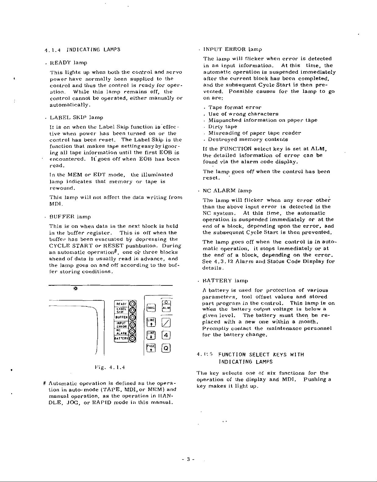
4.1.4
READY
-
lights
This
power
control
ation.
control
automatically.
.
LABEL
is
on
It
tive
when
control
function
all
ing
encountered.
read.
the
In
lamp
rewound.
This
lamp
.
MDI
.
BUFFER
This
is
the
in
buffer
CYCLE
an
automatic
ahead
the
lamp
fer
storing
if
Automatic
tion
in
manual
DLE,
INDICATING
lamp
when
up
normally
have
thus
and
While
cannot
SKIP
when
this
be
lamp
the
power
has
been
that
makes
information
tape
It
or
MEM
indicates
will
EDT
not
lamp
on
when
buffer
has
register.
been
START
operationÿ,
data
of
auto-mode
JOG,
is
on
goes
conditions.
O
operation
operation,
or
RAPID
LAMPS
both
been
control
the
lamp
operated,
Label
has
been
reset.
tape
off
goes
mode,
that
memory
affect
datainthe
evacuated
RESET
or
usually
and
off
BATTERY
Fig.
4.1.4
is
(TAPE,
as
the
mode
the
remains
Skip
turned
The
setting
until
when
the
next
This
by
pushbutton.
one
read
according
READY
LABEL
SKIP
1
BUFFER
IS
INPUT
ERROR
m
NC
ALARM
m
m
defined
MDI,
operation
control
supplied
is
ready
either
function
Label
easy
the
EOB
the
illuminated
or
data
block
is
off
depressing
or
three
in
advance,
as
or
this
in
and
to
for
off,
manually
is
or
on
Skip
by
EOB
first
has
is
tape
writing
is
when
blocks
to
the
0
0
0
0 0
@
0
the
opera¬
MEM)
in
HAN¬
manual.
servo
the
oper¬
the
effec¬
the
is
ignor¬
been
from
held
the
the
During
and
buf¬
and
the
is
•
INPUT
The
in
automatic
after
and
vented.
or
on
.
.
.
.
•
.
If
the
found
The
reset.
.
NC
The
than
NC
operation
end
the
The
matic
the
See
details
.
BATTERY
A
parameters,
part
when
given
placed
Promptly
for
P.5
4.
ERROR
lamp
an
input
the
subsequent
the
Possible
are:
format
Tape
of
Use
wrong
Mispunched
Dirty
tape
Misreading
Destroyed
FUNCTION
the
detailed
via
lamp
ALARM
lamp
above
the
system.
a
of
block,
subsequent
lamp
operation,
of
end’
12
4.3.
.
battery
program
the
level.
with
the
battery
FUNCTION
INDICATING
key
makes
selects
of
it
The
operation
key
will
information.
operation
current
information
of
memory
information
alarm
the
goes
lamp
will
At
is
suspended
goes
a
block,
Alarm
lamp
is
used
tool
in
battery
The
a
contact
the
light
lamp
flicker
block
Cycle
causes
error
characters
paper
select
code
when
off
flicker
input
this
depending
Cycle
when
off
it
stops
and
for
offset
the
control.
output
battery
one
new
the
change.
SELECT
LAMPS
one
of
display
up.
when
is
suspended
has
Start
for
on
tape
contents
key
of
display.
the
when
error
is
time,
immediately
upon
Start
is
the
immediately
depending
Status
protection
values
voltage
must
within
maintenance
KEYS
six
functions
and
error
At
this
been
the
paper
reader
is
error
control
any
detected
the
then
control
Code
This
WITH
MDI.
is
time,
immediately
completed,
is
then
lamp
t&pe
at
set
can
has
error
automatic
error,
the
prevented.
is
on
the
Display
various
of
and
lamp
is
below
then
a
month.
personnel
Pushing
detected
pre¬
to
ALM,
be
been
other
the
in
at
or
in
auto¬
or
error.
stored
is
a
re¬
be
the
for
the
go
the
and
at
for
on
a
3
-
Page 8

\6\
0
fa
[bj
ALM
select
To
status
‘
|DGN[
To
select
signal
.
PRM]
f
To
select
of
parameters.
.
[c
OM
select
To
(MDI)
operation.
•
[POS]
To
select
rent
positions
.
[OFS]
To
select
tool
of
Re-pushing
key
alternate
lows
the
in
.
g
0
S
(Alarm)
1
this
codes.
(Diagnosis)
this
status
(Parameter)
this
(Command)
]
this
of
the
(Position)
this
(Offset)
this
offset
DON,
of
EOT
switches
©
FyUCTlO**'
|ÿ|g§§|3|S]|§
,
-
-
--
—
00(1)00(1]
000000
Fig.
key:
key
key
.
key
key
command
key:
key
.
key:
key
values.
mode
changing
-
4.1.6
for
key:
for
key:
for
key:
for
for
for
PRM,
makes
ADD«£
--
display
display
display
display
data
display
display
SS
-
OFS
them
the
of
of
or
or
for
of
or
keys
display
alarm
input
writing-in
writing-in
automatic
various
writing-in
or
function
,
-
gg
,
x
-
©d)
©d)
/output
COM
as
and
as
ton
DATA
cur¬
fol¬
the
4.1.6
These
ter
-
Note:
[
/
command.
CAN|
1
the
keyed.
AUX
system
|~»1
operation
4.1.7
These
as
point),
all
meter
value
keys
when
Special
(Slash)
1
(Cancellation)
numeric
(Auxiliary)
EOB
keys
(Q)
through
numeral
data,
.
ADDRESS
are
writing
S
000000
@00000
0
@
@00000
@
@00000
key:
value
operation.
key:
.
KEYS
DATA
consist
can
and
values
and
KEYS
to
designate
in
Fig.
characters
For
or
key:
Not
used
of
,
(§)
©
be
used
as
so
on,
various
ADDPtSi
©
4.1.6
an
key:
address
for
twelve
(minus)
tool
optional
For
Not
a
for
writing-in
offset
in
addition
an
address
data.
cancellation
data
used
usual
keys
and
(7
(4
d
G
block
erroneously
a
for
system
in
total,
(a
Q
vaLue,
command
to
charac¬
skip
usual
decimal
of
such
para¬
of
such
(1)
Normal-
(2)
Wide-display
Pushing
facilitate
pushing
wide-display
any
of
the
it
.
display
one
normal
makes
A
block
---
using
racters
A
--
ing
block
displayed
these
-
display
the
four
display
of
designated
can
large
(line-display).
whole
page
designated
can
keys
operation.
change
or
line
be
displayed
size
cha¬
contain¬
line
or
widely
(page-display).
can
be
then
Another
the
to
-4-
Y)0
@0
L)@
®®(§)
@(D©
®®(D
©@©
Fig.
4.1.7
.1
0
H
„
Page 9
NOTES:
•
depressing
By
writing-in
R),
or
(P),
keying
EXAMPLE:
increment.
G),
©.©.©.
(D,
0,
(in
case
denotes
Use
a
feedrate
©,
of
an
of
a
distance
the
In
O
INCH
inch.
decimal
decimal
the
data
trailing
case
[WR]
®>
*
input
)
point
data
(F
of
fWRl
+,
(X,
)
zero
0.01
means
a
key
point
Y,
or
can
mm
125.00
means
decimal
Q
key
Z,1,J,
a
be
least
when
time
omitted.
125.40
point
input
mm
data
K,
mm
•
-
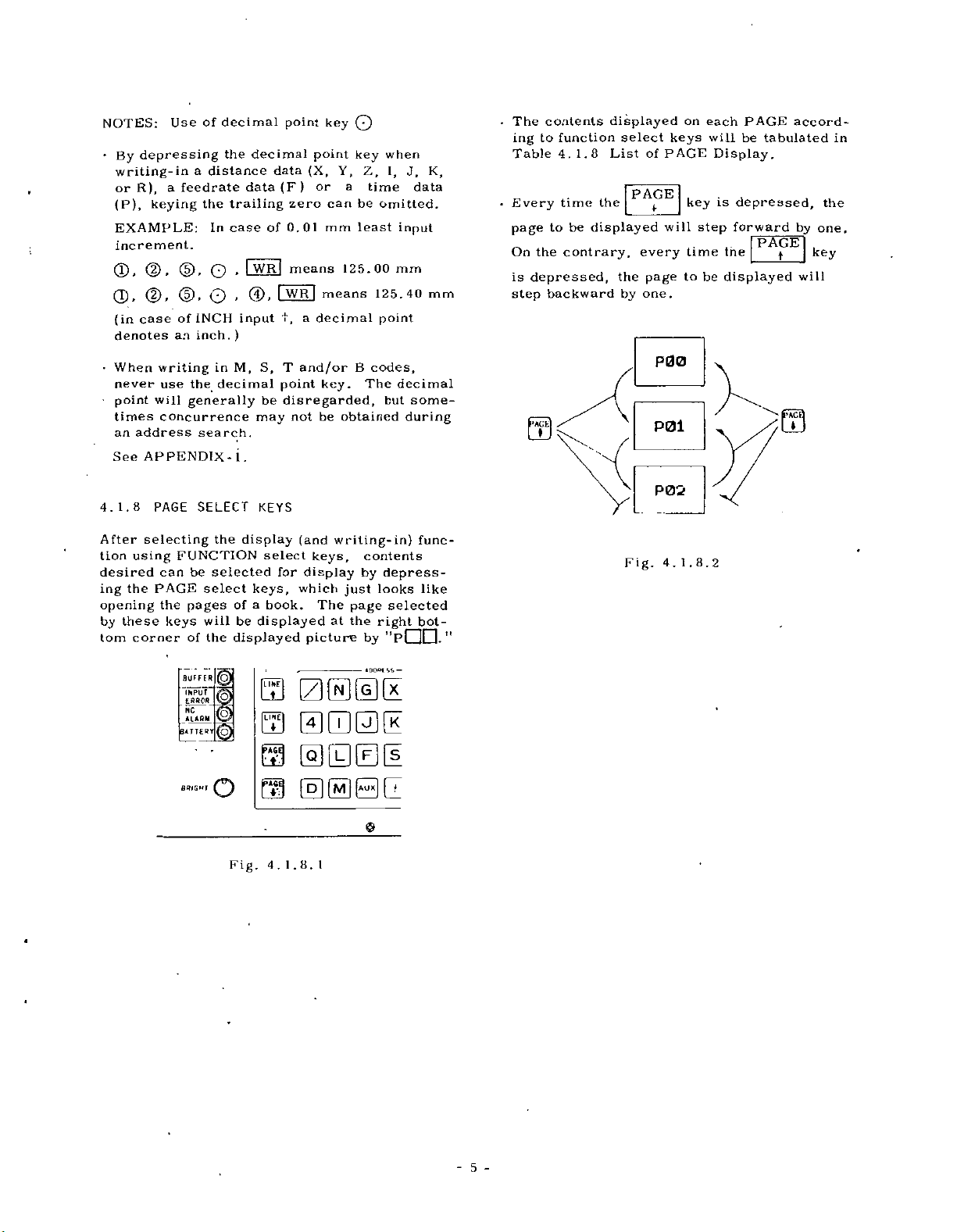
The
ing
Table
Every
page
On
is
step
contents
function
to
4.1.8
time
be
to
the
contrary,
depressed,
backward
displayed
select
List
PAGE
the
displayed
the
by
of
every
page
one.
on
keys
PAGE
key
will
time
to
each
will
Display.
is
step
be
PAGE
be
tabulated
depressed,
forward
PAGE
the
displayed
1
accord¬
the
one,
by
key
will
in
•
When
never
•
point
times
an
See
1.8
4.
After
tion
using
desired
the
ing
opening
these
by
corner
tom
writing
use
will
concurrence
address
APPENDIX-
PAGE
selecting
FUNCTION
can
PAGE
the
pages
keys
of
BUFFER
ThPifnÿC
£SR0R
NC
ALARM
BATTERY
BRIGHT
in
M,
the
decimal
generally
search.
SELECT
the
be
selected
select
of
will
the
displayed
[OJ
<§>
O
may
1
.
KEYS
display
keys,
a
be
displayed
0
0
0
T
S,
and/or
point
key.
be
disregarded,
not
be
(and
select
book.
for
keys,
display
which
The
at
picture
(ZKEGEItK
000(K
@00(1
(HIESCL
03
B
codes,
The
obtained
writing-in)
contents
by
looks
just
page
the
right
by
ADOBI
decimal
some¬
but
during
func¬
depress¬
like
selected
bot-
"pQIZL
—
P00
fr'ACfcl
UJ
Fig.
P01
P02
4.
m
1.8.2
"
Fig.
1.8.
I
5
-
4.
Page 10

Table
4.1.8
List
of
PAGE
Display
F
POSITION
COMMAND
(Except
mode)
unction
o
POS
_o
COM
EDT
Page
POO
P01
P02
P03
(P04)
P05
POO
POI
P02
(Note
1)
Displayed
Current
display
Current
display
Incremental
display
Current
collective
(Servo
(Note
Display
number
subprogram
Command
(Modal)
data
Input
Stored
display
position
A
position
B
position
lag
3)
of
of
part
(9
contents
position
display
value
display)
_
remaining
repetitions
___
data
display
display
program
/picture)
lines
____
of
_
wide-
•
When
key
first,
POO.
•
The
tents
changed
pressing
key.
Remarks
the
is
depressed
it
displayed
can
FUNCTION
displays
con¬
be
de¬
by
a
PAGE
[!§
mode)
(EDT
§5FF
OFFSET
O
PRM
PARAMETER
o.
DGN
DIAGNOSIS
[A§
ALARM
Note
Note
Note
1:
2:
3:
The
Although
key,
No
display
POO
display
P03
(Note
POO
to
POO
to
PDD
POO
to
PDD
POO
will
the
remains
can
2)
be
displayed
unchanged.
made
be
Editing
wide-display
part
program
(9
lines/
picture)
value
offset
Tool
(20
display
Parameter
(5
sets/page)
sets/page)
wide-display
INPUT/OUTPUT
(8
display
code
messages)
than
can
SYSTEM
the
sets/page)
be
wide-display
Alarm
(with
and
blank
a
alarm
in
code
status
picture
with
other
wide-
signal
the
renewed
MEM
NO.
The
when
functions
alternate
pushing
cutes
display.
At
containing
signated
block)
played.
For
up
alarms
displayed
mode.
depressing
by
at
"0."
FUNCTION
depressed
as
switch,
it
again
"wide-
the
"
this
time,
a
line
be
can
multi-alarming,
to
5
types
can
.
the
a
de¬
(or
dis¬
be
a
key,
first,
and
exe¬
page
of
PAGE
i
S'
t
—
'
CL
*u
<L>
tJX)
CO
CL
CL.
on
-u
0)
-a
5
6
-
Page 11

NOTES:
the
If
-
page
PAGE
t
executed.
case
In
flickeringly
designated
•
When
selected
key,
PAGE
first
the
or
played
4.1.9
LINE
"line"
"The
in.
LINE
displayed
picture
PAGE
display,
the
or
key
line
displayed
.
LINE
select
or
keys
by
key,
of
COM
"block"
number
at
key
1
it
returns
the
opposite
a
wide-display,
be
displayed
"line"
normal-display
depressing
by
key
.in
is
depressed,
of
keys
(or
a
data
SELECT
all
the
bottom
2-digit
to
picture
are
in
of
other
is
depressed
"block."
or
the
be
KEYS
to
order
line"
number
to
P0G,
operation
"o"
the
at
(line-display)
DGN,
EDT
the
displayed)
renewed
designate
to
display
designated
operations)
of
right
"CUD."
during
while
mark
headofthe
PRM,
mode,
head
line
of
will
an
object
and
using
will
the
displayed
can
will
or
if
the
the
with
OFS
be
write-
be
is
the
(the
page
dis¬
the
be
last
the
The
•
tion
4.1.9
display
line
.
Every
line
one,
by
ed,
depressed
matically.
ta
display
selected
key
List
(line-display),
or
block
time
block
or
while
backward.
.-T
)=
contents
of
LINE
will
the
to
makes
r
=
>•
f
Fig.
LINE
be
when
N
N
N
AN
N
N
NIB?
of
be
will
Display.
be
displayed.
*
displayed
the
Keeping
the
line
I
0
1
02
1
03
I
I
04
5
0
t
106
4.
1.9.2
each
tabulated
the
already
is
key
LINE
t
the
pointer
G91
G4G
XS000*
G4S
G45
G45
Y-S000*
LINE
the
For
depressed,
will
step
'
key
LINE
step
G01
X-4000
Y7000*
G0Z
1
0
G
a
with
in
Table
normal-
designated
forward
is
depress-
key
auto¬
23
Z
-
Y4
X30
X50
func¬
a
Note:
number
a
"line"
belongs
BUFFER
S
BUTTERY
SDIGHT
A
"line"
over
is
designated,
will
m
©
m
o
Fig.
stated
pages.
the
automatically
be
@1
EH
0
ID00II
0
4.
1.9.
herein
Because
the
•OOOESS
0B0IH
@@011
©
1
a
has
of
"page"
to
determined.
—
serial
this,
which
once
it
7
-
-
Page 12

Table
4.1.9
List
of
LINE
Display
unction
F
Jj
POS
POSITION
S2.
COM
COMMAND
(Except
EDT
in
mode)
COM
COMMAND
EDT
mode)
(
in
OFS
OFFSET
PRM
PARAMETER
2Z
DGN
DIAGNOSTICS
Line
(Note
T00
T99
N00
N99
XO0
X99
ZOO
Z99
Display
Editing
display
I)
to
to
Tool
play
of
Parameter
(To
part
(
offset
(To
TDQ
display
Parameter
to
to
INPUT
display
of
set
or
X
/OUTPUT
(To
Diagnostics
ZDD
program
block).
1
value
display
)
display
a
set
No.l~lf~~l.
display
)
contents
dis¬
set
a
of
signal
No.
)
a
Remarks
LINE
The
operation
affect
When
is
key
first,
pointer
be
will
When
TION
depressed
already
line
displayed.
line
A
*
display
designated
operation
LINE
keying-in.
won't
display.
the
the
FUNCTION
depressed
block
1
points
displayed.
this
key
assigned
data
desired
can
key
key
that
FUNC¬
is
first,
will
by
of
or
be
out
be
an
a
the
;>>
o,
m
x3
c
cfl
(
.
—
Q.
CD
5
to
e
u
o
NOTES:
.
When
"page"
page
.
When
display)
twice)
the
in
ignated
l
l
o"
mark
headofthe
a
as
a
DGN,
EDT
Note
LINE
which
well
display
by
"line"
will
ALM
ALARM
Although
1:
the
key
displayed
the
as
the
goes
depressing
PRM.
mode,
designated
"block")
(or
flickeringly
line
is
depressed
line
to
or
a
"page"
the
number
will
the
again
OFS
be
line
displayed
will
beyond
line
belongs
renewed.
be
wide-display
(consecutively
or
containing
be
COM
displayed.
key
will
displayed
block).
(or
not
block
be
the
to,
(page-
key
a
des¬
at
renewed
is
renewed.
the
the
-
8
-
by
•
Designation
following
of
tion
Address
-
stored
Line
line
a
in
DGN
depressing
operations
LINE
search:
program,
part
number
number,
be
will
The
line
won't
ation
display.
the
a
line
of
PAGE
or
Point
designation:
the
designated.
key
affect
L.INE
can
addition
in
keys.
line
oper¬
be
out
key,
By
for
made
the
the
to
pointer
directly
OFS,
through
the
opera¬
PRM
a
on
keying
or
the
Page 13

"line11
A
-
"page11
A
LINE
the
In
*
while
•
Depressing
ously
4.1.10
ORG
key
absolute
4.3.4
See
tails.
moves
may
key
operation.
MEM
the
AS
makes
ORG
used
is
coordinate
Current
READY
T.BfCt/rs
SKIP
BUFFER
ERROR
*c
ALARM
BATTERY
by
happen
mode,
is
key
the
both
line
number
(ORIGIN)
when
system
Position
g
0
(oi
Xzf
0
Fig.
operating
be
to
the
LINE
depressed.
LINE
u00,f
KEYS
a
position
by
Display
gggg
000®
000®
4.1.10
the
renewed
key
keys,
G92
PAGE
is
effective
simultane¬
forcibly.
display
is
set
for
rgNCÿiOi1*
-
iS
*DOH€
-
via
key.
on
atn0."
the
the
the
de¬
4.1.13
These
and
storing
effective
.
ERS
1
istodelete
It
the
|
INS
•
is
It
.
ALT|
is
It
memory.
|STR
•
is
It
buffer
T*
!tSS
00®
EDITING
are
keys
a
part
only
|
(ERASE)
mode.
EDT
[(INSERT)
to
store
(ALTER)
to
modify
(STORE)
1
to
used
register
ON
for
the
in
key
a
key
a
block
key
or
key
store
into
r
-
..
-
©®®
KEYS
editing
program
EDT
block
of
change
a
block
the
CO.’
O*T*
(ERS,
a
mode.
data
of
data
memory.
-
—
stored
into
a
data
*
INS,
in
into
block
Z
the
written
ALT,
part
memory
the
the
data
0
program
memory
memory.
in
in
STR>
and
in
the
the
4.1.11
WR
key
using
buffer
4.1.12
AS
key
a
tape
"Address
WR
is
the
ADDRESS
register.
AS
is
to
or
part
Search11
(WRITE)
store
to
(ADDRESS
start
searching
program
(A
DA
®@
®®
©@
©O
Fig.
for
the
—
KEYS
and
.
address
DATA
SEARCH)
of
memory.
further
0
Z
@]
0
M
Z
12
4.
I.
data
address
details.
Z
0
keys
KEYS
keyed
See
©
into
data
4.3.14
in
the
®0®
KEYS
in
effective
TAPE
OUT
This
key
ing-out
program
TAPE
IN
This
key
storing
the
into
TAPE
CHK
This
key
collation
program
part
program.
TAPE
TAPE
the
(TAPE-OUT)
of
.
(TAPE-IN)
of
memory.
(TAPE
4.1.14
TAPE
in
except
are
KEYS
CHECK)
are
automatic
only
to
is
the
is
to
the
part
is
to
between
and
tape
©®®
4.
Fig.
(TAPE
to
start
the
in
the
start
stored
key
start
program
CHECK)
start
the
the
13
1.
OUT,
the
operation
EDT
key
punch-
part
the
key
the
part
stored
®
tape
mode.
m
TAPE
operation
mode.
IN,
They
-9-
Page 14

4.1.15
This
key
executed
Move
*
Buffer
Alarm
-
•
Tool
•
Auxiliary
•
Label
Memory
Sequence
-
*
RST
code
G
-
(When
code
G
•
•
G
code
this
release
cancel
function
function
pointer
number
KEY
the
RESET
cancel
clear
rewind
reset
control.
cancel
RESET
resets
by
command
register
code
offset
skip
signal-transmission
A
of
group
contents
the
ALT]
D
6)
+
+
[STR|
Z
@
of
C
group
D
of
group
key
the
if
ON
"GOO"
of
parameter
"G40"
’GSO”
m
Operations
are:
cause
©
is
eliminated
No.
09
be
to
is"0.n
4.1.16
These
reader.
TAPE
-
This
manually.
causes
set
effective
is
manually
TAPE
switches
FEED
is
the
o
o
a
switch
the
switch
or
o
O
tape
FEED
AND
are
mounted
switch
to
Setting
during
the
to
feed.
R
to
automatically.
ft
SYSTEM
1
PARAMETER
CHECK
2
1
LOAD
4
TESTifti
1,
TEST
1
5
&
o
I
Fig.
SYSTEM
and
feed
switch
(reverse).
the
operation,
4.1.16
To
o
J
above
rewind
rewind
TAPE
FEED
-«©ÿ
F
NO,
to
This
k
SWITCHES
the
the
(forward)
F
the
either
o
O
O
o
tape
tape
tape.
switch
by
The
following
the
RESET
Current
-
•
Modal
When
G
code
F
*
commands
•
S,
T
and
*
Memory
parameter
NOTE:
remote
operation''
3
will
key.
position
G
codes
the
contents
A
of
group
B
commands.
contents,
data,
Depressing
reset
pushbutton
in
this
3)
0
-
Fig.
4.
not
be
valuesofeach
(except
manual.
of
is
such
etc.
the
for
parameter
not
RESET
is
n
15
1.
affected
C
affected.
tool
as
defined
and
©
by
axis
No.
offset
key
operating
D
groups)
09
or
as
"Reset
is”
values,
the
l,11
.
SYSTEM
Set
tion.
follows.
11
0”
:
For
prevented.
i
r
1":
write
To
Cycle
"2":
collate
To
control
”3m:
store
To
NO.
switch
the
Functions
SYSTEM
usual
operation.
PARAMETER
parameters.
is
Start
CHECK
the
the
with
LOAD
the
switch
at
M01f
its
of
prevented.
system
source
maintenance
during
each
Writing
At
program
tape.
setting
this
tape
the
usual
parameters
position,
stored
into’
are
the
opera¬
as
the
the
in
control.
is
10
-
Page 15

"4":
The
case
in
memory
the
turn
"5":
Writing
case
the
of
return
TEST
usual
of
position
TEST
of
"l"
of
memory
position
(0)
operation
"0"
is
SYSTEM.
contents
are
omitted.
1)
(
parameters
PARAMETER.
contents
are
omitted.
permitted
Self-diagnostics
and
checking
is
effective
Self-diagnostics
and
checking
simularly
of
zero
likewise
of
zero
of
re¬
4.2.2
Depressing
both
off
tem
First
in
(NC
TURNING
the
servo
simultaneously.
operation,
depress
button
usually
to
READY)
results
cut
the
OFF
POWER
and
control
take
the
EMERGENCY
the
off
signal
in
turning
POWER
OFF
However,
the
following
servo
is
interrupted,
pushbutton
powers
power.
the
to
for
stabler
procedure.
STOP
machine
be
The
causes
turned
sys¬
push¬
NRD
which
power,
too.
POWER
4.2
4.2.1
Check
the
referring
details.
for
inspections
Depress
•
the
control
in
read
power
shown
•
Depress
on
turn
READY)
is
normally
When
•
power,
nal
returns
will
lamp
POWER
J
ON/OFF
TURNING
machine
to
the
Operations
are
the
POWER
power.
about
is
ready
by
alarm
POWER
the
the
servo
signal
supplied.
the
NRD
and
the
be
ON
POWER
APPROX.
2
SECONDS
¥
ON
machine
as
two
is
MRD
back
lit.
I
I
i
i
I
OPERATION
POWER
before
follows.
The
seconds.
for
turning
code
power.
sent
signal
to
ON
I
I
I
l
I
turning
tool
builder's
after
ON
pushbutton
internal
on,
"31."
ON
pushbutton
The
out
when
turns
(MACHINE
the
control,
CONTROL
(NC
NRD
POWER
SF.RVO
(NC
NRD
MACHINE
(MACHINE
MRD
J
READY
1.AMP
on
completion
timer
the
Then
which
NRD
the
the
on
READY)
the
POWER
READY)
READY)
POWER
READ')
power,
manual
of
to
turn
will
servo
can
again
(NC
NC
power
machine
READY
pre-
be
to
sig¬
on
be
•
Depress
the
Fig.
4.2.3
Connect
EOF
shown
operation
POWER
the
control
CONTROL
CONTROL
SERVO
NRD
MACHINE
MRD
READY
4.2.2
REMOTE
the
COM
and
below.
YASMAC
POWER
the
power.
POWER
READY
POWER
(NC
READY)
POWER
(MACHINE
LAMP
ALARM
CODE
Sequence
power
terminals
Then
be
can
ON/OFF
EON
EOF
COM
EMERGENCY
STOP
t
READY)
BLANK
of
TURNING
ON/OFF
the
made
exactly
pushbuttons.
MACHINE
OFF
pushbutton
Turning
ON/OFF
pushbuttons
the
on
remote
POWER
OFF
Operation
off
PUSHBUTTONS
control
turning
same
the
REMOTE
BUTTON
OFF
REMOTE
ON
BUTTON
to
to
panel
ON
as
cut
EON,
/OFF
with
off
as
Fig.
ALARM
CODE
4.2.1
"11"
Sequence
'’28"r
of
BLANK
Turning
on
Operation
11
Fig.
4.2.3
ON/OFF
Connections
Pushbuttons
of
Remote
-
Page 16
4.3
DISPLAY
AND
WRITING
OPERATION
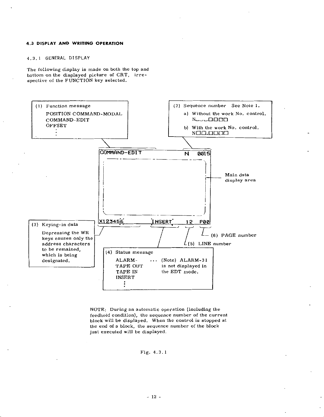
4.3.1
The
following
bottom
spective
(1)
display
displayed
FUNCTION
the
DISPLAY
message
COMMAND-MODAL
GENERAL
the
on
of
Function
POSITION
COMMAND-EDIT
OFFSET
is
made
picture
key
COMMAND-
on
both
of
selected.
the
CRT,
ED
top
irre¬
IT
and
(2)
Sequence
a)
Without
NÿoÿOODD
b)
With
NdO.niDCO
N
001
number
the
the
S
work
work
Main
display
No.
See
Note
No.
control.
data
1.
control.
area
(3)
Keying-in
Depressing
causes
keys
address
be
to
remained,
is
which
designated.
data
the
only
characters
being
WR
the
NOTE:
feedhold
block
the
just
X1254S6
(4)
During
condition),
will
of
end
executed
Status
ALARM
TAPE
TAPE
INSERT
be
displayed.
a
block,
will
message
-
OUT
IN
an
automatic
the
be
*1
NSERT*
...
sequence
the
When
sequence
displayed.
4.3.1
Fig.
(Note)
is
not
the
EDT
operation
number
the
number
12
(5)
ALARM-31
displayed
mode.
(including
control
of
of
is
L
LINE
in
the
stopped
the
j
block
(6)
number
the
current
PAGE
at
number
-
12
-
Page 17
4.3.2
Command
mode.
except
data
tfEDT
4.6
EDT
the
in
Set
1.
other
Depress
2.
lights
First
page
command
the
of
The
a.
register
a
feed
DISPLAY
data
The
procedure
in
+M
mode.
MODE
the
than
the
up.
depressing
number
data
data
hold.
can
any
for
the
COM
data
to
shows
during
COMMAND
OF
be
mode
the
)
SELECT
EDT
POO
of
make
to
one
to
be
displayed
the
an
always
displaying
of
is
command
mode.
and
key,
the
POO,
block.
contents
automatic
DATA
displayed
follows.
as
switch
COM
is
data
then
key
which
The
as
of
operation
command
display
a
mode
to
the
causes
displays
conditions
follows.
the
in
(See
lamp
active
any
or
the
the
d.
Depress
3
.
a.
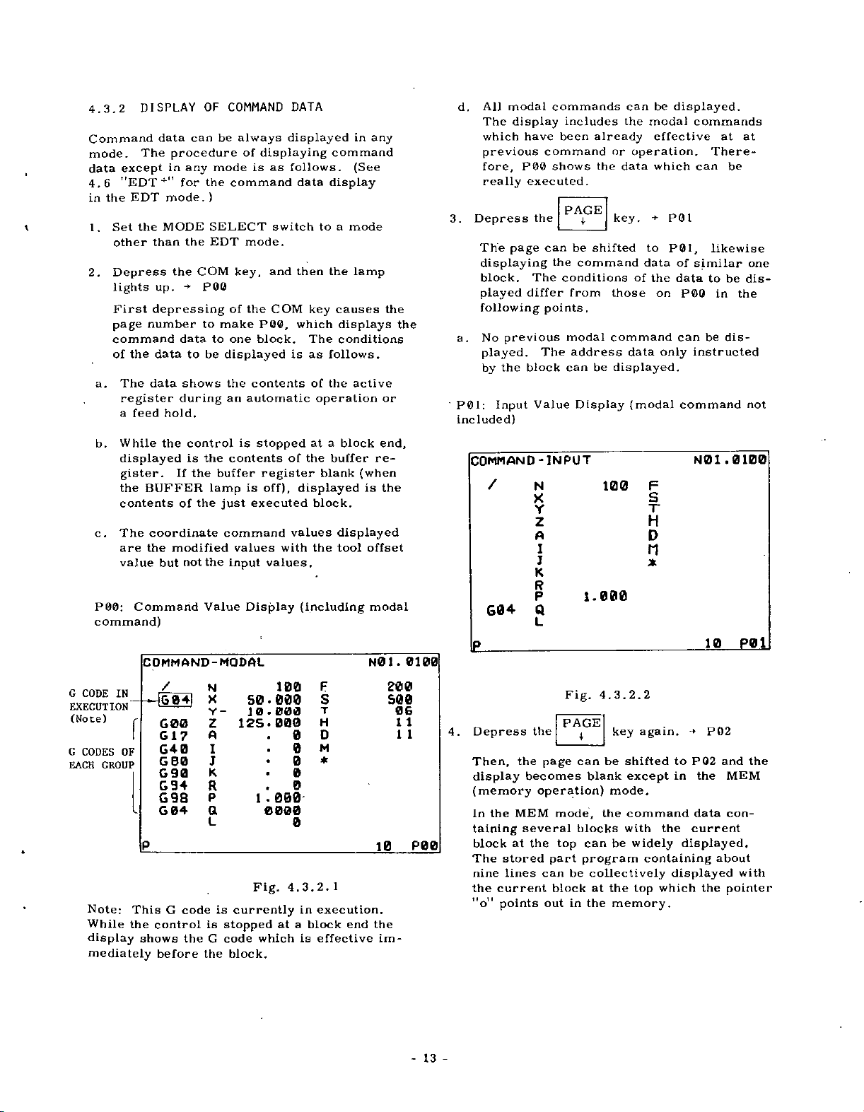
P01:
included)
modal
All
The
display
which
previous
P
fore,
really
The
page
displaying
block.
played
following
previous
No
played.
the
by
Input
commands
have
been
command
00
shows
executed.
the
can
the
The
differ
points.
The
block
Value
includes
already
the
PAGE
be
shifted
command
conditions
from
modal
address
can
be
Display
can
the
modal
or
operation.
data
+
key.
to
data
the
of
those
command
data
displayed.
(modal
displayed.
be
effective
which
P01
P0I,
of
data
on
POO
can
only
command
commands
at
There¬
can
be
likewise
similar
be
to
in
be
dis¬
instructed
at
one
dis¬
the
not
b.
c
.
POO:
command)
G
CODE
EXECUTION
(Note)
G
CODES
GROUP
EACH
Note:
While
display
mediately
While
displayed
gister.
the
contents
The
are
value
Command
the
If
BUFFER
of
coordinate
the
modified
but
control
is
not
COMMAND-MODAL
IN
/
iG04|
G00
f
G17
G40
OF
G
80
90
G
94
G
G98
04
G
P
This
the
control
shows
before
code
G
theGcode
the
the
the
buffer
lamp
just
command
the
Value
N
X
Y-
Z
A
1
J
K
R
P
a
L
is
is
stopped
the
is
stopped
contents
register
is
executed
values
input
Display
50.000
10
125.000
1
Fig.
currently
which
block.
of
off),
with
values.
100
000
-
.
000
0000
4.3.2.
at
at
the
blank
displayed
block.
values
the
(including
F
S
T
H
D
0
M
0
0
*
0
0
0
in
execution.
a
block
is
effective
a
block
buffer
(when
displayed
tool
1
end
re¬
is
offset
modal
N01.
10
the
im¬
end,
the
200
S00
06
1
1
0100
1
1
P00
COMMAND-INPUT
/
G04
the
stored
lines
current
points
the
the
becomes
MEM
several
the
at
4.
Depress
Then,
display
(memory
In
taining
block
The
nine
the
"o"
N
X
Y
z
A
I
J
K
R
P
Q
L
Fig.
PAGE
I
can
page
operation)
mode,
blocks
top
part
can
be
block
out
in
100
1.000
3.2.2
4.
key
be
blank
mode.
the
can
be
program
collectively
the
at
the
memory.
F
S
T
H
D
n
*
again.
shifted
except
command
with
widely
containing
which
top
PG2
to
in
current
the
displayed,
displayed
N0
the
data
the
1
10
P02
.0100
and
MEM
con¬
about
pointer
P0
the
with
1
13
-
-
Page 18
FLICKERING
Memory
P02:
COMMAND
&KI100
N101
N10Z
--
N10JS
N
4
0
1
N105
J-
N106
N107
G04
691
G4G
*5000*
S
64
G4S
1000*
G
49
Y-
5000*
Program
1000*
P
601
X400O
Y7000*
02
6
G01
0500
Z-
Y4000
X3000
K3000*
Wide
Display
N0
F1S0*
D10
Y3B00
0100
1
.
F500*
14000
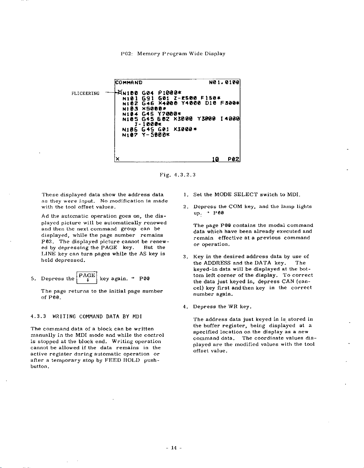
These
as
with
Ad
played
and
displayed,
P02.
ed
LINE
held
5.
Depress
The
of
4.3.3
The
command
manually
is
stopped
cannot
active
a
after
button.
displayed
they
the
the
automatic
picture
then
The
depressing
by
key
depressed.
page
P00.
WRITING
in
at
allowed
be
register
temporary
were
tool
the
while
displayed
can
the
returns
data
the
the
data
input.
offset
operation
will
next
command
the
the
turn
PAGE
4
COMMAND
of
MDI
mode
block
the
if
during
stop
show
No
values.
be
automatically
page
picture
PAGE
pages
key
the
to
a
block
end.
data
automatic
FEED
by
X
the
modification
goes
group
number
cannot
while
again.
initial
DATA
can
while
and
Writing
remains
address
on,
key.
the
•+
page
BY
MDI
be
written
the
operation
operation
HOLD
is
the
renewed
can
remains
renew¬
be
But
AS
key
P00
number
control
in
push¬
data
made
dis¬
be
the
the
or
Fig.
is
P02
10
3
3.
2.
4.
1,
2.
3.
4.
Set
Depress
up.
The
data
remain
or
Key
the
keyed-in
tom
the
cel)
number
Depress
The
the
specified
command
played
offset
MODE
the
the
-*•
P00
P09
page
which
effective
operation.
the
in
ADDRESS
data
left
corner
data
just
first
key
again.
the
address
buffer
location
are
value.
SELECT
COM
contains
have
desired
and
will
keyed
and
WR
data
register,
data.
the
modified
been
of
then
key.
The
key,
already
a
at
address
the
displayed
be
the
in,
just
being
the
on
switch
the
and
the
modal
previous
data
DATA
display.
depress
in
key
in
keyed
displayed
display
coordinate
values
to
MDI.
lamp
command
executed
command
by
key.
at
To
CAN
the
is
asanew
values
with
lights
use
The
the
correct
(can¬
correct
stored
the
and
of
bot¬
at
in
a
dis-
tool
14
-
Page 19

Writing
Command
Value
COMMAND-
G01
t
G01
617
G40
|WK|KEY
GOO
G
90
G94-
98
G
MODAL
N
X
Z
A
1
J
K
R
P
a
L
4-0
30
50
206
.
000
-000
000
•
0000
F
S
T
H
0
D
M
0
0
*
0
0
0
Y30.
KEY
j
IN
NO
1
400
1000
10
.
0205
01
10
10
POO
s.mjoi.0
Fig.
4.3.3
OF
The
operating
POS
+
PO0
is
thus
position
following
"79."
position
on
that
UNITt
position
amount
manually
be
command.
is
the
displayed
the
CAN
and
CURRENT
be
can
and
key,
depressed
resulting
will
"79"
No.
to
the
CURRENT
(See
.
of
changed
updated
is
to
set
ADDRESS
keys
POSITION
always
displayed
procedure
the
then
first,
the
in
selected
=
"0":
be
displayed
A.
display
be
NOTE.
display
shows
machine
automatically,
or
even
even
if
by
the
MACHINE
data,
designate
then
key,
simultaneously.
as
is
lamp
the
page
display
set¬
by
is
POSITION
)
the
move¬
initiating
LOCK
LOCK
an
depress
the
NOTE:
the
address
at
the
address
designated
Repeat
5.
data
of
E>.
Depress
the
input
NOTES:
If
the
a.
operation
ready
The
b.
dataofcodes
cannot
Cutter
as
1
G4
by
COMPENSATION
The
c.
data
display
written-in
the
turn
For
d.
writing-in
skip,
depress
ready
and
then
The
bottom
character
the
a
block
the
commands
RESET
by
written
be
changed
Radius
or
to
P00.
page
first
the
written
depress
WR
data
left
address."
steps
have
CYCLE
key
MDI,
can
G42
.
executed
be
data,
to
"/"
in
key
WR
in,
operation
key
corner.
will
and
been
START
address
be
4
except
3
will
depressed
all
the
cancelled
be
except
MDI
by
Compensation
(Refer
of
C
to
TOE-C843-
will
To
read
depress
P01.
the
for
like
"/,
To
key.
first
key
the
WR
The
called
until
written
pushbutton,
be
executed.
during
command
F,
M,
operation
2
.
4.
be
out
PAGE
the
optional-
n
n
l"
cancel
like
in
key.
will
character
remaining
"currently
command
the
in.
out.
S,
is
C
TOOL
13
5
checked
only
I
and
the
"/,
erase
thr
data
and
T
as
executed
•
30.
the
key
block
then
"/"
M
then
writing
al¬
B
far
)
by
to
-
al¬
11
O'
4.3.4
The
at
follows
1.
+
as
any
Depress
lights
When
turns
mode
One
ting
A.
DISPLAY
current
mode.
.
Where
The
•
same
DISPLAY
•
The
position
the
up.
this
key
to
POO,
of
current
the
of
parameter
parameter
current
as
current
accumulated
ment,
which
the
The
•
MODE
either
cannot
C92
display
switch
position.
•
To
reset
axis
using
POS
the
15
Page 20

B.
•
Where
displayed
The
set
cally
shows
movement
operation.
parameter
up
accumulated
the
by
by
current
G50
both
"79”
No.
position
command.
amount
manual
the
=
"l":
is
The
of
and
automati¬
display
machine
automatic
To
B.
axis
depress
irrespectively
selection.
P02:
reset
using
Current
the
displayed
ADDRESS
CAN
Position
key.
of
The
mode
Display
data,
key
axis
selection
designate
and
simultaneously
is
reset
(EXTERNAL)
B
and
an
to
page
"0"
•
The
tion
system,
does
•
Only
MODE
position.
•
To
after
DRESS
values
Reset
operation
HANDLE)
operation
the
NOTE:
influence
POSITION
tive
.
P00:
Current
T
POS
1
X
Y
Z
A
display
based
not
interrupt.
the
switch
reset
the
designating
key
will
operation
blocks
The
DISPLAY
the
P00
DISPLAY
-
UN
ION
1250
shows
on
as
display
display,
and
be
modes.
ORG
or
while
are
Position
I
43S
the
programmed
as
far
is
set
is
the
the
"0."
must
key
read
display.
UNIT,
VE
RSAL
50
always
the
updated
to
depress
axis
displayed
be
(RAPID,
is
not
BUFFER
ahead.
LOCK
For
Display
.469
.775
.008
the
current
manual
if
MACHINE
with
coordinate
made
JOG,
effective
lamp
switch+
the
this
switch
A
(UNIVERSAL)
N01
0
posi¬
coordinate
operation
the
LOCK
LOCK
ORG
key
the
AD¬
in
manual
STEP
during
is
on
does
CURRENT
is
effec¬
.
not
.
POSITION-EXTERNAL
X
Y
Z
A
X
or
or
3.
Depress
The
page
mental
in
axis
The
display
A.
Updated
being
tion.
Updated
B.
starting
Once
ation
value
celled.
Incremental
P02:
Fig.
the
turns
movement
execution.
shows:
distance
executed
distance
point
mode
the
mode,
in
the
PAGE
manual
.
50
4.
30.
1
0.000
4.
3.
key
4
to
P02,
value
to
under
to
the
in
turned
is
displayed
the
Value
469
775
008
2
4.
again.
showing
of
the
end
the
manual
the
manual
operation
Display
N01
both
X-
of
the
automatic
operation.
to
automatic
incremental
can
15
PB1
P02
an
incre¬
and
block
opera¬
operation
can¬
be
Z-
oper¬
2.
A.
Depress
The
page
position
The
tion
DISPLAY
the
display
display
as
that
turns
UNITt
Fig.
PAGE
4
to
B.
shows
of
4.3.4.
key.
P01,
the
the
.
1
-
showing
same
CURRENT
P01
current
i
s
the
current
posi¬
POSITION
pee
16
0
0
N01.
5
1
peg
POSIT
X
Y
z
A
I
-INCREMENT
ON
Fig.
50.
IS
3.4.
4.
.
3
000
000
-
Page 21

Depress
4.
The
positions
The
current
which
reference
point
RETURN
POSITION
the
turns
page
.
"MACHINE"
positions
has
its
-zero-
is
the
position
operation.
(UNIVERSAL)
PAGE
1
to
"0"
point.
key
POO,
collectively
position
in
the
coordinate
(Reference-
returned
)
again.
display
coordinate
just
by
(EXTERNAL)
•*
N0
P03
showing
shows
system
on
zero-
ZERO
.
1
the
the
4.3.5
The
tool
memory
be
can
the
automatic
The
operating
1
Depress
.
lights
When
shows
corresponding
designated
DISPLAY
offset
the
of
made
up.
this
the
values
control.
at
any
operation.
procedure
OFS
the
key
tool
in
previous
OF
TOOL
time
key,
is
depressed
offset
a
to
are
"line
OFFSET
kept
The
in
any
is
as
and
data
operation
the
in
display
mode
follows.
then
first,
ofanoffset
number"
VALUE
tool
of
even
the
lamp
the
already
(see
offset
a
value
during
display
number
NOTES).
5.
Depress
The
(see
6.
Depress
The
program
to
NUMBER
GRAM.
7.
Depress
The
NOTE:
With
following
P04:
•
The
display
of
X
1250.469
455
-
Y
z
A
(INCREMENT)
X
r
Z
A
display
the
remaining
APPENDIX-3
page
SYSTEM
the
data
Servo
A
lag
mand
positions
coordinate
is
B
the
CURRENT
.
77
50*008
*000
50
15.000
the
on
NOTE).
the
is
displayed.
OF
the
returns
will
lag
value
positions
reset
S
0
o
0
Fig.
PAGE
PAGE
REPETITIONS
PAGE
value
is
value
3.4.4
4.
key
1
this
page
key
1
number
DISPLAY
key
1
to
the
to
NO.
be
displayed
display
between
and
displayed
the
of
also
by
POSITION
X
r
z
A
X
Y
Z
A
again..
will
again.
of
repetitions
For
OF
again.
initial
at
be
the
the
(in
current
the
DISPLAY
50*469
4*775
50*008
10*000
(MACHINE
185*
Z47*
60.
40.
IS
become
-*•
the
details,
REMAINING
OF
SUBPRO¬
-*•
page
or
"4"
on
P04.
updated
current
0.001
mm
position
reset
operation
332
0S6
751
167
P04
P05
P00
of
"5,"
com¬
UNITt.
)
P03
blank
of
sub¬
refer
P00.
tool
unit).
the
2.
Key
"H"
needed.
corresponding
played.
display
ber
Note:
If
numeral
designated.
"0!."
Depress
3.
The
displayed.
OFFSET
Hi
POS
X.
Note:
rent
4.
Depress
The
displayed.
in
2-digit
"D").
(or
A
If
shows
"10."
"l"
key
value
the
of
data
0
(UNIVERSAL)
On
the
position
the
of
data
number
The
of
set
to
H
II
"H,
the
depressed
"01"
This
LINE
]
an
offset
X-
4.
Fig.
lower
A
and
LINE
t
an
offset
WR
data
the
keyed-in
M
l,
contents
following
at
shows
key.
number
3.
half
increment
key.
number
following
key
for
It
0"
the
45
1
5.
of
operation
an
are
of
lowest
an
X
r-
Z
A
the
minus
a
character
offset
offset
value
keyed
an
the
plus
value
is
in,
offset
above,
2-digit
number
one
N01.
.
764
1250*469
435*775
50.251
.306
1
10
display
value
is
one
is
not
dis¬
the
num¬
is
is
P00
cur¬
shown.
is
a
17
-
Page 22

W
5.
OFFSET
y<H0
H
!
(o
6.
Depress
ide-Display
Depress
The
display
collectively
cluding
of
sets
H00
X-
H01
X
02
H
X
03
H
X-
04
H
X
H0S
X~
H06
X
H07
X
0B
X-
9
an
When
Mark
Note:
acter
displayed.
"ll"
of
OFS
the
turns
showing
the
offset
data/page).
2S.
4.70S
10.887
50.218
4S.
9.447
77-295
125.030
150.003
number
offset
flickers)
is
displayed
offset
the
Fig.
PAGE
the
4
key
to
number
168
764
number
4.3.
again.
the
wide-display
the
H
Mil
H1Z
HI
H14
HIS
H
H
W10
H19
"09"
as
5.2
key.
data
designated
10
X-
X
X
X-
3
X
X
X
6
1
X
17
X
X
is
an
address
and
mode
a
of
page
.
N0
1
45
4.998
89.98?
200
21.S64
09
designated.
char¬
is
"D"
in¬
{20
.764
.463
P01
not
sponding
will
become
the
above
to
an
object
displayed
for
such
number
display
"OH]"
and
writing-in.
.
This
displayed
LINE
key
be
not
but
in
the
display
4.3.6
Writing
always
Writing
0
0
0
0
0
the
keyed
set
The
1.
2.
WRITING
or
possible
tool
incremental
is
in
and
value
operation
Depress
lights
up.
A
of
set
ed
is
displayed
in
Key
character
be
operated.
A
of
set
the
keyed-
number
the
in
affected
modes
OF
modification
independently
offset
value.
added
displayed
procedure
OFS
the
for
data
offset
an
"H"
offset
tool
in
offset
OFS,
algebraically
or
Simultaneously,
(at
for
the
the
bottom
keyed-in
right)
can
be
and
PRM
the
of
of
is
The
as
is
offset
LINE
POS,
OFFSET
the
completed
written
a
new
as
then
and
number
by
TOOL
value
key,
an
(normal-display
value
number
"line
is
desired
The
corresponding
number"
also
number
"D."
the
number.
renewed
key
COM
tool
at
operation
the
to
offset.
follows.
WR
is
be
DGN
modes,
operation
and
VALUE
offset
by
value
stored
the
lamp
designat¬
mode).
following
need
key
displayed.
display
subsitituted
the
by
ALM.
value
mode.
writing
just
to
is
off¬
a
not
The
o
ed
Depress
7.
The
minus
of
displayed
8.
Depress
Cancelling
turns
display
previous
NOTES:
A
"line
operation
bottom
•
In
displaying
key,
parameter
Mark
page.
the
the
page
flickers
the
page
one.
renewed
the
back
shows
number"
is
right
respective
number
to
turns
(The
first
PAGE
t
returns
o
Mark
page.
)
data.
OFS
the
wide-display,
the
to
the
operation.
designated
always
a
by
and
writing
the
page
the
at
head
line
key.
back
to
flickers
(The
again.
key
normal-display.
line
designated
displayed
kept
-digit
data
or
number,
by
of
diagostic
2
number
line
of
displayed
the
first
by
OFS,
an
page
the
at
the
the
PRM
offset
number
plus
the
of
number
head
line
mode
by
previous
at
the
r
1
number,
renew¬
data.)
of
re¬
The
the
or
corre-
one.
line
DGN
3.
4.
5.
in
Key
a
plus
The
character
(in
case
The
keyed-
bottom
number
first
key
again.
Depress
Depress
will
data
value.
value.
set
data
The
will
be
acter
unerased.
Repeat
necessary
stored
a
tool
number)
of
left
is
mis-
and
the
the
be
The
displayed
erased
the
into
offset
of
writing
in
data
corner
then
WR
WR
added
summed
off,
steps
tool
the
value
desired
is
X,
an
will
of
keyed,
key
key.
key.
algebraically
value
at
leaving
3
offset
memory.
(an
to
used
absolute
be
displayed
the
depress
the
in
Then
the
left
through
values
axial
be
for
value).
display.
correct
the
a
is
new
bottom
address
the
4
have
address
written
the
address
the
displayed
the
to
tool
until
in.
at
the
the
If
CAN
number
stored
off¬
section
char¬
the
been
18
-
Page 23

KEY
WRJ
OF
POS
XS.
FSET
H08
(UNIVERSAL)
04
KEY
N0
1
.
X
IS.
927
)
34
Z50.
X
Y
100.
Z
A
IN
66
30
l
S00
.
033
.
000
P
0
1
©
©(i
OFFSET
OFFSET-
OFFSET-8
CUT.
H
CMP.
N01.
A
X-
Y
Z
A
X
643
Y
G49
G44
Z
A
9
G4
G40
X
TOOL
IS
.SZ2
1S.S22
Z00.6S7
S
•
044
S
CENTER
0
0
0
0
0
so
H3
nec
H06
HOC
00
D
1
gas
NOTES:
To
enter
-
mental
DATA
cancelled
be
Tool
-
erased
Writing
-
can
be
automatic
•
When
matic
active
and
one.
next
4.3.7
The
current
of
data
Procedure
1
.
Depress
up.
shows
in
the
played
of
Select
2.
key
displayed
the
value,
keyboard.
offset
by
and
always
the
offset
operation,
The
block.
DISPLAY
VALUES
each
is
When
the
previous
tool
offset
in
the
display.
,,P05n
and
the
[xyUEKSB]
—
Fig.
offset
new
depress
The
and
the
values
turning
stored
off
modifcation
possible
operation
value
the
offset
OF
offset
are
CURRENT
register
new
tool
compensation
follows.
as
OFS
the
this
tool
"PQQ
as
key
key
offset
operation.
number
"
using
current
shown
4.3.6
data
CAN
offset
display
the
in
mode.
is
blocks
executed
value
values
and
is
depressed,
data
the
at
PAGE
I
tool
below.
instead
key
value
shows
in
memory
power.
of
tool
offset
mode
any
changed
buffer
in
is
effective
TOOL
and
function
then
already
The
page
designated,
bottom
key
offset
before
stored
0.
during
with
OFFSET
the
are
the
the
designated
including
right
or
values
incre¬
of
handling
will
values
including
auto¬
register
an
in
related
displayed.
lamp
display
are
dis¬
corner
PAGE
t
are
will
not
old
the
lights
be
EXAMPLE
A
B
C
NOTES:
"P05"
only
Depressing
and
change
However,
playing
P04
4.3.8
Various
parameter
their
tape
termined.
details.
possible
operation.
P05
or
POO.
PARAMETER
contents,
code
Tool
position
Tool
center
designated
X
direction
the
Y
direction.
Tool
position
Tool
center
(the
mm
and
tion
H06)
in
applied
Tool
position
(tool
G40
effect.
in
page
PAGE
by
LINE
the
when
page.
parameter
storage
and
rapid
See
The
parameter
any
in
Y
is
position
is
contents
+53.
by
the
Z
the
to
radius
in
OFS
key
keys
display
LINE
the
DISPLAY
have
of
operation
traverse
the
mode
J.
1&.52?
offset
compensated
by
and
"
offset
compensated
of
mm
044
direction.
and
X
offset
C:
compensation
mode
operation.
cannot
between
is
key
display
been
the
control.
conditions
parameter
display
even
during
DESIGNATED
A:
15.
15.522
+
B:
H31)
(the
No
Y
axes.
can
select
P04
operated
may
stored
rate,
table
can
ir>.sÿ
POSITION
from
522
mm
+200.657
by
theXdirec¬
in
contents
offset
cancel)
selected
be
the
and
POO.
duringdis-
be
changed
in
According
such
be
will
for
always
be
automatic
the
the
mmM
in
is
05
P
the
as
de¬
the
in
the
of
is
page
to
to
19
-
Page 24

The
Depress
1.
lights
gnated
Key
2.
ter
keyed-
key
"9,
"90"
Note:
above,
designated,
operating
up.
in
"N,
in
operation
M
11
0,
will
If
procedure
the
number
a
2-digit
and
"
number
for
"
be
"1"
the
PRM
set
A
will
the
is
example,
shown.
key
smallest
show
to
key,
of
parameter
be
number
parameter
will
not
is
depressed
as
is
and
displayed.
following
be
displayed.
needed.
and
2-digit
the
parameter
follows.
then
for
Key
the
following
number
the
lamp
a
desi¬
a
charac¬
data
in
"N,
parameter
"01"
"01."
of
The
the
"
the
WR
is
FLTCKERINC
PAR
&N90
N91
N
N
AM
92
ETER
X
Y
Z
A
-
X
Y
Z
A
X
Y
2
A
Fig.
2
1
35
16
4.
NPl.
S
N95
X
M94
Y
Z
A
X
Y
Z
A
8
0
0
a
0
0
0
1
1
600
£00
000
S*6
0
0
0
0
0
0
50
2
8.
3.
PI
8
3.
Depress
The
data
displayed.
4
.
Depress
The
data
is
displayed.
PARAMETER
N90
PY)5
N
Note:
current
coordinate
lower
N39)
to
LINE
the
the
of
of
parameter
a
1
LINE
t
parameter
X
Y
Z
A
Fig.
a
special
system
-
(Special
(MACHINE.)
For
position
section,
key.
key.
4.
display
will
number
number
X
Y
Z-
A
1
3.8.
parameter
of
be
displayed
parameter
plus
minus
N01.
25
1
35
16
.
32
645
416
.
7S0
200
.
10.443
1
90
display,
the
"MACHINE"
O
S52
one
at
no.:
x
Pia
the
to
one
the
N00
6.
Depress
The
page
Depress
7.
The
page
Depress
8.
Cancelling
turns
NOTES:
•
all
For
axis
of
the
ing
During
•
cated
by
operation.
key
4.3.9
Except
parameter
the
WRITING
for
machine
Whenever
parameter
manufacturer.
the
turns
the
turns
the
the
normal-display.
the
to
parameters
the
data
address
wide-display
the
mark)
"o"
the
setting
have
data
performance
a
modification
data,
PAGE
PAGE
PRM
1
over
t
back
key
key.
by
key.
by
again.
one.
one.
wide-display,
requiring
not
be
will
displayed
"X."
mode,
can
be
PARAMETERS
function,
been
set
is
therefore,
the
designation
the
moved
by
the
corresponding
and
application.
desired
consult
mode
right
line
the
optimum
machine
the
for
re¬
follow¬
(indi¬
LINE
to
the
Wide-Display
5.
Depress
The
collectively
cluding
(5
sets
o
Mark
designated.
display
the
of
will
the
PRM
turns
showing
parameter
data
flicker
key
to
/page).
at
again.
the
the
number
the
wide-display
a
of
data
designated
parameter
page
number
mode,
in¬
The
by
the
Where
operating
setting
data
is
are
it
con¬
as
is
are
erased
the
tool
parameter
interlocked
"0"
at
or
changed.
of
data
builder.
that
so
parameters,
writing
The
parameters
SYSTEM
not
accidentally
desired
sult
the
procedure
follows
-
20
-
.
NO.
to
modify
machine
for
switch
the
Page 25

1
2.
3.
4.
.
Depress
lights
The
Key
ing
needed.
The
will
Key
ber)
For
tion
address
than
Set
will
the
SYSTEM
up.
parameter
be
displayed.
a
in
parameter
the
"N."
parameter
be
displayed.
a
data
in
desired
all
parameters
of
axis,
"X11
N
can
the
PRM
to
key
(any
be
NO.
key,
data
The
WR
data
(an
axial
be
in
address
effective).
switch
of
number
of
written
not
a
number
and
a
designated
operation
key
the
address
in.
requiring
characters
at
"1."
then
desired,
keyed-in
plus
following
the
lamp
number
is
number
a
designa¬
follow¬
not
num¬
the
other
5.
6.
7.
8.
The
keyed-in
bottom
the
rect
and
first
Depress
The
keyed-in
parameter
parameter
the
address
corner
Repeat
the
necessary
Return
Depress
left
number,
then
the
will
the
the
the
data
corner
key
WR
data
storage
data.
character
erased.
be
steps
parameters
SYSTEM
RESET
will
of
depress
in
key.
will
and
The
3
through
be
the
the
be
address
at
NO.
key.
displayed
display.
the
correct
stored
displayed
left
the
above
5
have
switch
CAN
number.
into
as
data
bottom
been
to
at
To
cor¬
key
the
a
new
except
until
set.
M0.M
the
all
NOTES:
Data
*
are
With
•
automatic
details,
play.
Setting
-
address
characters
Address
•
Data
displayed
unless
of
parameters,
erased
not
parameter
refer
parameter
of
Display
of
parameter
SYSTEM
by
operation
to
the
tape
on
the
at
anytime.
0
turning
No.
4.3.
number
universal
of
numbers
NO.
—
once
at
00,
will
10
Operation
memory
Tape
They
switch
PARAMETER
N80
stored
the
off
be
at
Memory.
power.
totalized
displayed.
99
displays
with
display.
01to98
cannot
is
set
KEY
St!
in
memory,
time
Time
number
See
can
be
at
M1.M
X
IN
of
For
Dis-
active
of
4.5.4
be
changed
Fig.
4.3.9
•
If
stroyed,
•
SYSTEM
tape
.
Where
than
not
writing
the
not
of
any
reader.
"O"
start
SYSTEM
usually
N01.
1
80
parameter
alarm
NO,
the
SYSTEM
and
M4/f
the
parameter
NO.
set
Pt
6
code
switch
CYCLE
operation.
data,
switch
at
4
data
M17",
is
NO.
which
is
accidentally
will
provided
switch
START
On
completion
never
to
0.
is
for
be
displayed.
above
is
button
fail
The
test.
set
to
switch
at
set
de¬
the
other
can¬
of
back
is
21
-
Page 26

*
/
4-3-9
*
Table
ADD-
I
:
NO.
i
RESS
MEANING
7
O
/
Operation
9999.
Rapid
:
1
y
s
Rapid
505
A
X
Stroke
7y>0'Ufi,
Stroke
'
0
!
kfyf-xv-JilE
Leadscrew
0
*
!
Reference
4oj
i
Not
Traverse
J
=7.5
A
v
Traverse
RAPID,
bD-7fx
;
=
1
=
J'Mi’-l-
=
Required
(H)
Check
Check
OFF,
OFF,
*
00
01
02
.
/
!
I
*03
to
ts?
/_
*04
/
*05
/
06
*
i
Time
59.
mm
Error
Zero
g,
/
ON-OFF
Display
min
5
1
7
ON-OFF
Xho-?fx7U13]
1
*
1
*
H
Return
07
(M)
Rate
Rate
1
=
7
AW
»
=
Compen.
:
=
Required
n*
59.
»
Override
Dry
for
JOG
Machine
for
ON
_
ON
before
IS)
Setting
Run
ON-OFF
Cycle
Lock
Start
NO.
10
*
*11
*12
*13
14
*
15
*
16
*
17
*
18
*
19
*
*20
*21
*22
*23
*24
*25
Not
Used
08
*26
*27
09
!
RESETS©
Group
A
!
'
0
=
G
A7VU—
G
code
00,
1
1
7'C
When
:
=
3—
Resetting
1*7?
Held
*28
*29
ADD-
RESS
o
o
O
O
O
O
O
O
O
O
O
O
-
O
'
O
O
O
O
O
O
O
4-3-9
/*
m
PARAMETER
e-7*X7-f|j£!
Leadscrew
1
-7
;
=
2
*
£
MEANING
Error
mm
0.001
TABLE
-
*
Compen.
(1/3)
(1/3)
Values
NO.
*30
*31
32
*
*33
*34
*35
*36
37
38
*39
ADD¬
RESS
O
O
O
O
O
O
O
O
O
O
Multiply
;
Reference
'20*
fcf
Compensational
5
HU
First
M
r-
1
7
1
5
for
=
i
=
Parameter
f-x
7
=0.001
D-
b
Stroke
0.001
=
fg
Point
|U_hO-?f
First
Stroke
;1;
=
0.001
S2ÿl-n-7fx-;
Second
:
£2X
Second
!1''=
;
=
0.001
1
hO-7-f
0.001
**31
Not
Xho-7-f-iv?
Select
Area
3B4-11
Refer
Stroke
Stroke
Used
JB
to
c.'
MEANING
Leadscrew
No.
No.
Pitch
mm
7
Point
Check
mm
j
v
Point
Check
mm
Check
mm
7&f%
i7
Check
mm
fSailgaT
Stroke
for
sMtf-x
Stroke
4*11
a*
Error
for
20
y
L*
for
Point
Point
Check
x
rmzz&m
E,
L.
f-
E.
L.
(Max)
(Min)
(g*fil
(Max)
(E'J'fifi
(Min)
Check
Compen,
C.
C
Page 27
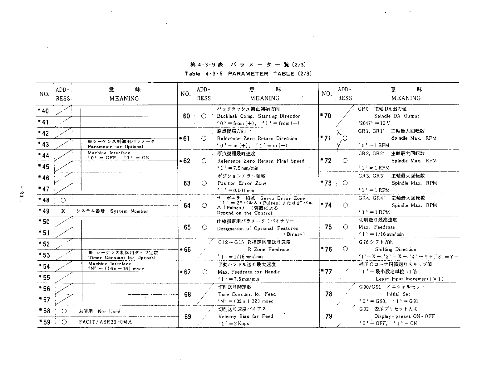
*4-3-9
Table
4-3-9
/<
35
PARAMETER
X
-7
*
TABLE
(2/3)
K
-
(2/3)
ADD
.
RESS
I
1
-
:
MEANING
NO.
*40
*41
*42
M3
*44
*
45
*'>-T
Parameter
Machine
505
OFF,
*
i
i
for
Interface
Optional
*1*
-9
>
=*
ON
*46
*47
to
GO
*48
*49
O
X
System
Number
NO.
60
•61
*62
63
64
ADD-
RESS
O
O
O
O
O
7
7
'*7
'
Backlash
505
Reference
4
05
=
=to
7
from
«£S«BSItaUE
Reference
5
4
7.5
1
—
#yy
3
Position
4
4
X
Depend
1
1
=0.001
*
5
(
Pulses)
Error
=
on
MEANING
y
iffllEMSaSln]
Comp.
(+)
,
Zero
(+)t
Zero
mm/min
Zone
mm
<$$(
the
Control
Starting
}
1
Return
5
4
1
Return
Servo
(
Pulses)
tKafc*
:
—
=
to
Direction
(
from
—
Direction
)
(—
Speed
Final
Error
tfZlt
1
1
Zone
27
*50
65
*51
*52
*53
*54
*55
*56
*57
*58
*59
O
Designation
/
G12-G15
*66
16)
for
Optional
msec
*67
Timer
Constant
Machine
*N5
O
.
O
FACIT/ASR33
=
Mot
Interface
(16n
Used
—
68
69
/
O
/
“
/
4
Max.
4
f3jsij&*m5&s
7
Time
'N*
y-
Velocity
'
;
1
s
1
1
1
1/16
—
Feedrate
=
7.5
Constant
{32n
=
2
=
Optional
of
RfllEErdljgOiiS
Zone
R
mm/min
for
mm/min
for
32)
+
Bias
for
Kpps
r
Feedrate
Handle
Feed
msec
x
Feed
Features
(
Binary
)
NO.
*70
*71
*72
*73
*74
75
*76
*77
78
79
ADD-
RESS
O
O
O
:
O
O
O
GRO
'"2047'
GR1,
CRT
J
4
=
1
GR2,
CR2'
'
M
*
GR3,
GR3'
;
1
1
=
GR4,
GR4'
4
=
'
1
mmos&mis.
Max.
5
4
=
1
G76
•>
4l‘-X+,*2s
=
/
G90/G91
J
4
0
—
C92
4
J
=
0
MEANING
£ttDAdi?Jfi
Spindle
1
=
1
10
RPM
RPM
DA
V
Spindle
Spindle
±«**iae»
Spindle
RPM
1
Spindle
RPM
1
Feedrate
mm/min
1/16
7
h
Shifting
Least
G90,
Sÿ7-|J
Display
OFF,
=
Input
Initial
4
dT
-
414
Direction
X-,i4i
1
preset
Output
Max.
Max.
Max.
Max.
(le-
Increment
Set
J
G91
~
All]
h
7
ON
-
RPM
RPM
RPM
RPM
Y
-f
—
(XI)
1
ON-OFF
,
Y
=
—
48'
Page 28

*
Table
4-3-
4-3-9
9
&
A*
5
PARAMETER
*
*
TABLE
(3/3)
J*
-
(3/3)
ADD¬
NO.
RESS
EIA/ISO©g*MSiJAtD
80
81
4
TV
TV
4
0
0
5
=
fi7
Check
=
'
EIA/IS0
82
"83
to
4ÿ
84
,
5
4
=
0
i
INCH
MM/
J
4
=
0
i
Touch
4
'
0
=
85
Auto
-
OFF,
ON-OFF
OFF,
3-
Code
EIA,
Designation
,
MM
Buzzer
OFF,
Not
MEANING
Select
4
1
1
*
Designation
;
'
1
4
1
/
ON-OFF
414
Used
4
s
=
-
=
=
=
ON
ON
ISO
INCH
ON
i*
NO.
90
91
92
*
93
*
94
95
I
86
Rapid
4
0
Reference
5
OFF,
-
4
Return
4
1
—
ON
ON-OFF
96
*
Z\
0
5
=
101SAW
=
OFF,
Not
Designation
F4.0,
415*
X
Data
4
1
Used
10
=
F4.
ON-
5
=
ON
1
OFF
mm/
min
98
*99
*97
87
88
89
/
Y.
4
!
A*»ÿ
Command
4
0
[
Feedrate
,
ADD-
;
1
RESS1
O
O
O
O
O
O
;
O
i
O
,
O
;
?
7
Backlash
!
:
=0.001
T
7-o-yttis
5
Mirror
;
5
4
;
0
-
1
tt«»aa*(RPG)
Traverse
5
4
=
1
1
;
Traverse
5
4
=
1
Rapid
4
5
=
1
I
Accel.
;
4
1
=125/8
Reference
|
:
4
=
1
*
:
Reference
s
=0.001
M
SF,
MF,
i
SFb
Delay.
5
4
1
=
-tVfKd
*
Memory
:
4
1'
Notice
-l
7
V
7
Value
mm
Image
OFF,
Rate
7.5
mm/
Rate
1/16
mm/
Traverse
7.5
mm/min
»]«>*;£»
/Decel.
Zero
7.5
mm/min
Zero
TF,
Time
msec
1
>
Pointer
ch
=
1
i)
1)
«
MEANING
Axis
ON-OFF
5
4
ON
=
1
Clamp
min
(FC)
Clamp
min
Rate
Const,
Time
mm/sec2
Return
Return
mm
&tttS*lttfU]
BF
MF,
for
Display
3£
(RPG)
Speed
(FG)
Speed
for
Approaching
Final
Stroke
SF,
TF,
BF,
RT
Speed
and
SFb
1)
No.
No.
00
These
displayed
)
No.
2
No.
01
switch,
sition
3)
K
BMDftZtltZ'*?
Parameters
4)
ADDRESS
-n-to
Parameter
required
are
£5
00
and
99
cannot
at
01-98
to
98
and
of
SYSTEM
m
NOTICE
<£0*99
are
be
anytime.
H
SYSTEM
are
can
with
ffiflDO
with
the
display
for
written,
interlocked
changed
be
No.
/
-
mark
Ml0>Jg$€gg-r
li
Mark
O
selection
T'
but
No.
In]
A
switch
are
in
of
,
<£>
0
only.
be
can
-y
Ad
-y
f-
d
by
SYSTEM
only
when
is
optional.
ADDRESS
axis.
f-
4
a
tZ
£
1/
>T*Tp
'
*
J:
5
i
1
No.
po¬
the
<
7
*
Page 29
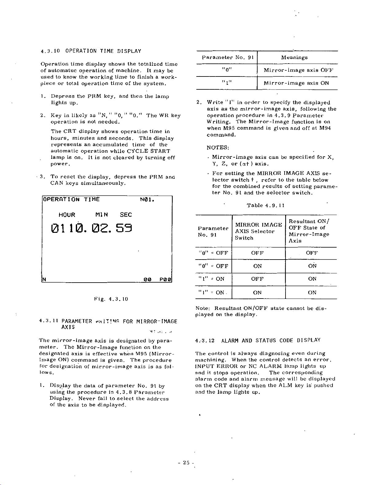
4.3.10
OPERATION
Operation
automatuc
of
to
used
piece
1
.
2.
3.
know
or
total
Depress
lights
in
Key
operation
The
CRT
hours,
represents
automatic
lamp
is
power.
To
reset
CAN
keys
OPERATION
HOUR
01
time
display
operation
the
operation
the
PRM
up.
likely
not
is
display
minutes
an
operation
It
on.
the
display,
simultaneously.
TIME
10.
TIME
shows
of
working
time
key,
as
"N,
"
needed.
shows
and
seconds.
accumulated
while
is
not
MIN
02.
DISPLAY
machine.
time
of
and
"0,
"
operation
cleared
depress
SEC
53
the
totalized
finish
to
the
then
"0."
This
time
CYCLE
by
the
It
system.
the
The
time
of
turning
PRM
N0
1
may
a
work-
lamp
WR
display
the
START
.
time
be
in
off
and
key
Parameter
Write
2.
axis
operation
Writing.
when
command.
NOTES:
Mirror-image
•
Y,
•
For
lector
for
ter
Parameter
No.
91
"0"
ii
"1"
as
M95
Z,
setting
the
No.
No.
in
the
mirror-image
procedure
The
command
(at)
or
switch
combined
91
and
MIRROR
AXIS
Switch
91
Mirror-image
Mirror-image
order
to
Mirror-Image
is
axis
axis
the
MIRROR
refer
,
+
results
the
Table
4.9.
IMAGE
Selector
specify
in
4.3.9
given
can
.
to
selector
11
Meanings
the
axis,
Parameter
function
and
be
specified
IMAGE
the
table
of
setting
switch.
Resultant
OFF
Mirror-Image
Axis
axis
axis
displayed
following
off
at
AXIS
below
parame¬
State
is
for
ON
OFF
ON
the
on
M94
X,
se¬
/
of
N
4.3.11
The
mirror-image
meter.
designated
Image
for
ON)
designation
lows.
1
.
Display
using
Display.
of
the
Fig.
PARAMETER
AXIS
The
Mirror-Image
axis
is
effective
command
of
mirror-image
the
data
the
procedure
Never
axis
to
be
4.3.10
axis
is
is
given.
of
parameter
in
to
fail
displayed.
FOR
MIRROR-IMAGE
designated
function
when
M95
The
axis
4.3.8
Parameter
select
the
00
by
on
(Mirror-
procedure
is
No.
address
the
91
P0
para¬
as
by
0
fol¬
"0"
=
=
"0"
"1”
=
"1"
-
Note:
played
12
4.-3.
control
The
machining.
INPUT
it
and
stops
alarm
the
CRT
the
on
and
OFF
OFF
ON
ON
Resultant
the
on
ALARM
is
When
ERROR
operation.
and
code
display
lamp
ON
display.
AND
always
or
alarm
lights
OFF
ON
OFF
ON
/OFF
STATUS
the
NC
when
up.
state
CODE
diagnosing
control
ALARM
The
message
the
AI.M
OFF
ON
ON
ON
cannot
be
DISPLAY
even
during
will
key
an
lights
be
is
displayed
detects
lamp
corresponding
dis¬
error,
up
pushed
-
25
-
Page 30
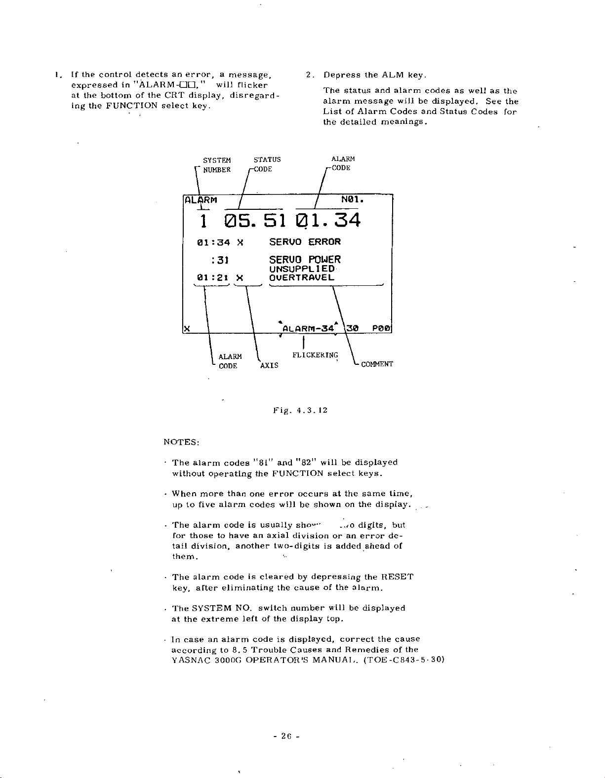
If
1.
the
control
expressed
at
the
bottom
the
ing
detects
in
"ALARM
of
FUNCTION
the
an
CRT
select
error,
-CIO,
display,
key.
M
a
message,
will
disregard¬
flicker
2.
Depress
The
status
alarm
List
of
detailed
the
the
and
message
Alarm
ALM
key.
alarm
will
Codes
meanings.
codes
be
displayed.
and
as
Status
well
Codes
as
See
the
the
for
ALARM
NOTES:
•
The
without
SYSTEM
NUMBER
1
01:34
01:21
alarm
operating
:
31
ALARM
CODE
05.
X
X
V
codes
STATUS
:ODE
51
SERVO
SERUO
UNSUPPLIED
OUERTRAUEL
ALARM-34
7
FLICKERING
AXIS
Fig.
,r
11
and
1
8
the
FUNCTION
01.
ERROR
POWER
4.3.
"82M
12
will
ALARM
N01.
34
A
be
select
\30
displayed
keys.
P00
COMMENT
•
When
up
The
•
for
tail
them.
•
The
key,
The
*
the
at
•
case
In
according
YASNAC
more
five
to
alarm
those
division,
alarm
after
SYSTEM
extreme
alarm
code
to
code
eliminating
an
alarm
to
3000G
than
one
codes
is
an
have
another
is
NO.
left
code
Trouble
5
8.
OPERATOR’S
error
usually
axial
two-digits
cleared
switch
of
the
-
will
division
the
cause
number
display
is
displayed,
Causes
26
-
occurs
shown
be
sho”-
by
depressing
MANUAL.
is
of
will
top.
and
the
at
on
~.*o
or
an
added
the
be
correct
Remedies
same
the
digits,
error
ahead
the
alarm.
displayed
(TOE
time,
display.
but
de¬
of
RESET
the
cause
of
-C843-
the
30)
*
5
Page 31
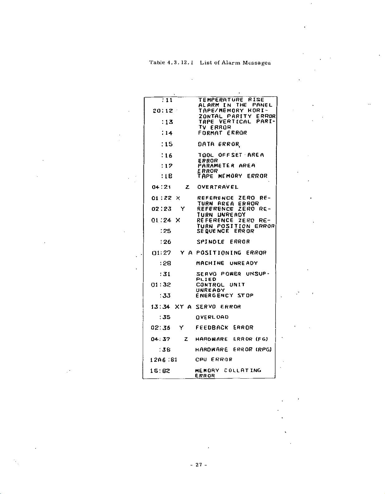
Table
4.3.
12.
1
List
of
Alarm
Messages
:
20
:
:
:
:
I
:
:
04:21
:
01
02:23
01:24
:2s
:
Ol:
:
:
:32
01
:33
14
is
16
17
IB
22
26
2?
28
31
11
12
13
TEMPERATURE
ALARM
IN
TAPE/MEMORY
ZONTAL
TAPE
TV
FORMAT
DATA
TOOL
ERROR
PARAMETER
ERROR
TAPE
Z
OVERTRAVEL
X
REFERENCE
TURN
REFERENCE
Y
TURN
X
REFERENCE
TURN
PARITY
VERTICAL
ERROR
ERROR
ERROR,
OFFSET
MEMORY
AREA
UNREADY
POSITION
SEQUENCE
SPINDLE
Y
A
POSITIONING
MACHINE
SERVO
PLIED
CONTROL
UNREADY
ENERGENCY
ERROR
UNREADY
POWER
UNIT
RISE
THE
HORI¬
AREA
AREA
ERROR
ZERO
ERROR
ZERO
ZERO
ERROR
ERROR
UNSUP¬
STOP
PONE
ERROR
PARI-
RE¬
RE¬
RE¬
ERROR
L
13:34
:
02136
0*:
:
12A6
15:82
3S
37
36
81
XY
A
Y
Z
-27-
SERVO
OVERLOAD
ERROR
FEEDBACK
HARDWARE
HARDWARE
ERROR
CPU
MEMORY
ERROR
COLLATING
ERROR
ERROR
ERROR
_
(FG)
(RPG)
Page 32
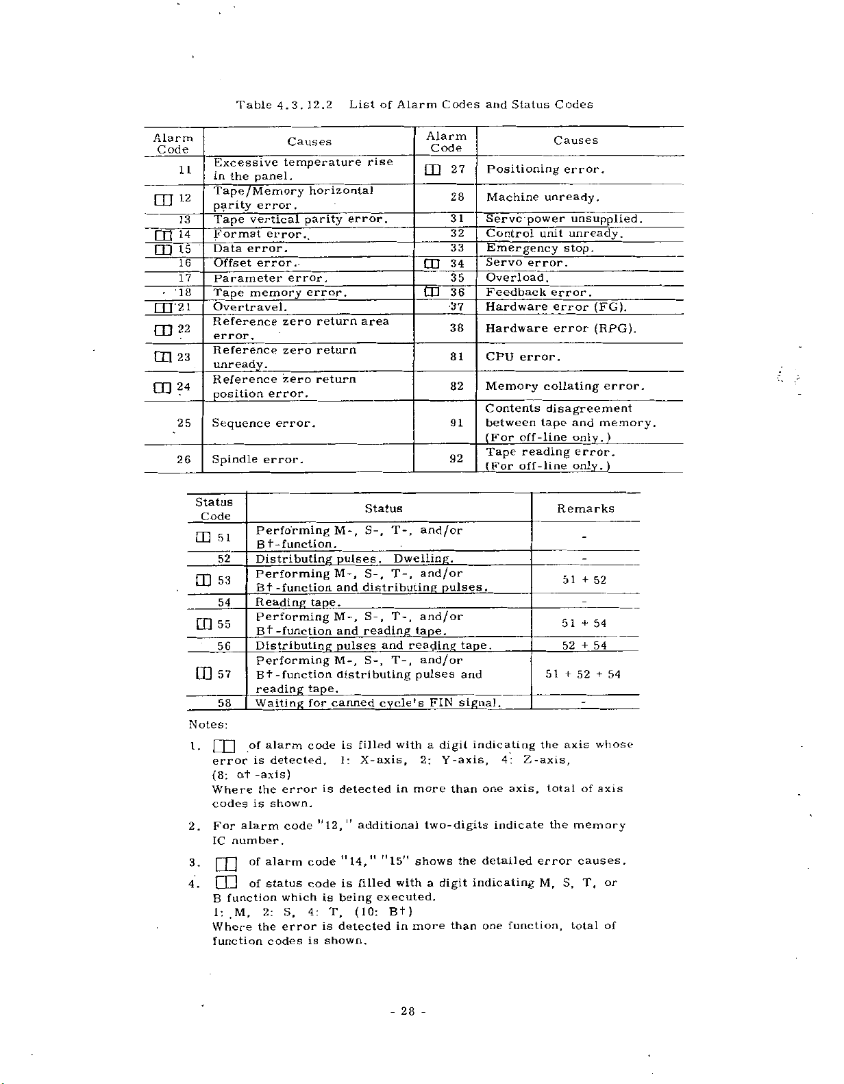
Table
4.3.12.2
List
of
Alarm
Codes
and
Status
Codes
Alarm
Code
CD
m
-
CO
m
CD
11
12
13
14
15
16
17
18
22
23
24
25
26
Notes:
2.
4.
Excessive
in
parity
Format
Data
Offset
Parameter
Tape
Overtravel.
Reference
error.
Reference
unready.
Reference
position
Sequence
Spindle
Status
Code
Q]
Q]
LD
'
_
tD
|
1.
error
(8:
Where
codes
For
IC
3.
B
1:
Where
function
T
Tape
l
the
panel.
ape/Memory
error.
vertical
error.
error..
memory
error.
Performing
51
Bt
Distributing
52
Performing
53
Bt
Reading
54
Performing
55
Bt
Distributing
56
Performing
57
Bt
reading
Waiting
58
alarm
of
]
is
-axis)
at
the
is
alarm
number.
alarm
of
|
|
|
I
1
status
of
function
2:
.M,
the
Causes
temperature
error.,
error.
zero
zero
_
zero
error.
error.
-function.
-function
-function
-function
detected.
error
shown.
code
which
S,
error
codes
horizontal
parity
error.
return
return
return
_
M-,
pulses
M-,
and
tape.
M-,
and
pulses
M-,
distributing
tape.
canned
for
code
detected
is
"12,"
code
code
is
being
4:
T,
detected
is
is
shown.
error.
area
distributing
_
filled
is
X-axis,
1:
additional
"14,
filled
is
(10:
rise
Status
S-,
S-,
S-,
reading
and
S-,
cycle's
11
11
executed.
T-,
Dwelling.
T-,
T-,
tape.
reading
T-,
pulses
with
in
more
15"
shows
with
Bt)
more
in
Alarm
Code
27
m
28
31
32
33
34
CD
35
36
CD
37
38
81
82
91
92
and/or
_
and/or
pulses.
and/or
and/or
FIN
a
digit
Y-axis,
2:
than
two-digits
a
digit
than
tape.
and
signal.
indicating
one
detailed
the
indicating
one
Positioning
Machine
Servo
power
Control
Emergency
Servo
error.
Overload
Feedback
Hardware
Hardware
CPU
error.
Memory
Contents
between
(For
off-line
Tape
reading
(For
off-line
Z-axis,
4:
axis,
indicate
error
function,
Causes
error.
unready,
unsupplied.
unit
unready.
stop.
.
error.
error
error
collating
disagreement
and
tape
only.
error.
only.)
Remarks
51+52
51+54
52
+
51+52+54
axis
the
of
total
the
memory
causes.
S,
M,
T,
total
(FG),
(RPG).
error.
memory.
)
54
whose
axis
or
of
-
28
-
Page 33

Table
4.3.
12.3
Display
Examples
of
Alarm
Codes
Combined
with
Status
Codes
Alarm
1.55.
54
.
.52
1C
.
Status
and
20.
01.21
36.81
Code
.12
12
A
horizontal
"12"
occurs
the
M-function
reading
in
the
TAPE
A
horizontal
"12")
occurs
(status
The
An
axis
during
The
a
"81").
code:
defective
overtravel
(additional
the
operation
mal-operation
(status
automatic
The
parity
while
(code:
mode.
parity
while
"54")
IC
(alarm
cannot
active
Meaning
error
simultaneously
"l")
number
alarm
of
”55"
error
reading
the
in
code:
code:
operation.
be
the
CPU
address
code:
(alarm
and
=
"51"
(alarm
a
memory
MEM
is
20.
"21")
"l")
continued
(alarm
is
IC36.
code:
executing
the
+
code:
mode.
of
occurs
due
tape
"54")
X-
to
code:
Note:
Under
will
execution
flicker
09.
at
the
82
of
bottom
M-,
S-,
of
T-,
the
Flickering
A
total
resulted
the
memory.
is
"09."
and/or
CRT
6TSM-F1N
I
error
from
B-function,
display.
(alarm
the
The
18
code:
seif-diagnostics
defective
the
following
PBB
"82")
ROM
is
of
number
message
29
-
-
Page 34

4.3.13
DISPLAY
INPUT/OUTPUT
OF
SIGNALS
Wide-Display
All
the
the
operator's
automatic
The
operating
1
.
Depress
The
designated
played.
Key
2.
displayed.
in
in
In
in
The
designated
displayed
DI
input/output
operation.
the
INPUT
a
diagnostic
in
case
of
a
2-
digit
of
case
a
2-digit
ON
/OFF
i
NOS
AG
signals
at
panel
procedure
DGN
key.
/OUTPUT
diagnostic
an
input
diagnostic
number
an
output
number
status
the
by
by
S
diagnostic
or
"1"
-7-6-S-4-3-2-1-0
can
time
any
as
is
signal
number
number
following
diagnostic
following
a
of
group
"0.”
checked
be
even
follows.
status
will
desired
number:
X.
number:
Z.
of
number
during
of
be
to
signals
Kiel
dis¬
will
.
the
be
on
Key
Key
be
5.
o
od
a
CJ
Si
6.
Depress
The
display
mode,
rently
displayed.
DIAGNOSIS
A
X60
X61
X62
X63
X64
X6S
X66
X
Depress
The
page
the
DGN
will
which
in
designated
7
10
1
0
00000001
01010100
00100010
000
67
0
0
1
Fig.
PAGE
the
turns
key
replace
a
page
diagnostic
S
6
11
1
10
111
0
0
:
OPEN
iCLOSED
4.3.
key.
t
the
to
again.
the
containing
3
4
10
0
1111
00000
0
8
13.2
plus
page
wide-display
the
number
1
Z
0
10
0
0
0
0
11
one.
cur¬
will
N01.
60
be
Note:
shows
designated.
3.
Depress
The
nostic
Depress
4.
The
nostic
X60
X
Keying
designates
the
group
number
group
number
10111010
:
0
OPEN
:
1
CLOSE
Fig.
4.3.
in
l"
"
diagnostic
the
LINE
I
signals
plus
LINE
t
signals
minus
of
status
the
of
the
of
D
1
13.
after
number
the
group
key
.
designated
will
one
key.
designated
will
one
"X,
"
be
displayed.
be
0
E
and
"6,
"
"01"
of
signals
the
by
the
by
displayed.
"0"
and
diag¬
diag¬
7.
Depress
The
Depress
8.
Cancelling
returns
NOTE:
moved
display
4.3.14
A
specific
searched
also
but
S
and
Y,
tion.
program
part
part
program
Further,
searched
ister
page
The
by
operating
.
ADDRESS
block
not
by
T,
A
part
attention
block
in
the
the
returns
the
DGN
the
back
line
only
address
all
according
program
in
in
won't
EDT
PAGE
t
back
key.
wide-display
the
to
normal-display
designation
the
LINE
SEARCH
on
the
part
the
by
character
to
to
the
TAPE
the
MEM
should
enter
mode.
key.
to
the
("o"
key
program
sequence
the
searched
be
mode,
EDT
or
taken,
be
into
page
mode,
mark)
during
number
such
following
while
mode.
because
buffer
the
minus
the
mode.
can
as
is
a
display
can
the
be
"N,
C,
opera¬
a
taped
stored
reg¬
one,
be
wide
"
X.
the
30
-
-
Page 35

1
Set
.
MEM
Depress
2.
lights
3.
Depress
Then,
the
Key
4.
desired
EXAMPLE
are
number
key
EXAMPLE
detected
less
5.
Depress
When
dress
the
tion
To
6.
the
NOTES:
•
A
block
enters
instructed
are
•
the
In
the
with
lamp
Leading
*
dress
search
N012.
All
•
modal
data
*
Operation
the
search
Reset
•
dress
so
causes
any
The
the
MODE
the
or
up.
the
stored
an
in
to
keyed-in,
mis
and
then
of
the
the
data
BUFFER
stops.
suspend
RESET
searched
the
modified
EDT
edit
buffer
tool
offset
is
on
zeros
characters
operation.
commands
one
enters
begins
CYCLE
is
operated
control
the
search
operating
operation
memory.
EDT.
the
the
LABEL,
part
address
be
1:
-keyed,
2:
MMft
number
the
address
concurs
the
key.
buffer
in
the
with
mode,
likewise
are
the
in
START
in
format
mode.
starts
SELECT
COM
RESET
program
searched.
In
MM01M
in
key
"M,
code
(address
AS
lamp
search
in
register.
same
tool
the
register
value
may
including
For
the
in
not
recognized,
buffer
with
in
before
the
error
key,
key.
SKIP
data
case
is
first
the
"-'V
"
is
to
of
M.
search
with
lights
the
TAPE
block,
offset
searched
without
and
in
tape
be
suppressed
example,
searched
the
is
key
the
EDT
(alarm
from
switch
and
then
lamp
is
rewound.
(or
only
that
"M,
be
to
depress
correct
When
be
searched,
search)
starts
instructed
the
and
up
operation,
a
If
coordinate
values.
so
on.
and
N
register.
searched
depressed
TAPE
Cycle
mode.
the
to
the
lights
address)
M
"0,
searched:
number
the
key.
and
the
or
MEM
tool
block
being
But
MEM
for
address
in
N12
blocks
and
only
block,
or
MEM
Start
Failure
code:
address
first
TAPE,
lamp
up
M
CAN
the
initially
regard¬
the
opera¬
depress
mode
offset
will
modified
BUFFER
mode.
all
means
including
after
after
n
14n)
and
1,
"
"
If
again.
ad¬
data,
is
values
enter
ad¬
update
if
a
mode.
ad¬
do
to
used
block
mode,
parameter
see
at
"0n
at
"
ON,
code
lights
is
displayed.
additional
POSITION
be
for
Y,
Z,
front
of
the
of
display
RESET
switch
LOCK
movement.
(VERTICAL
make
to
during
TV
Writing
4.3.9
•
•
*
l"
•••
the
if
the
in
during
up
mode.
a
in
block
character.
provided
three
a).
The
or
separately
tool
is
each
axis
unit.
button
is
not
affected
is
updated
on,
+
switch
is
STOP
button,
the
tape
check
No.
TV
Check
TV
Check
number
block
tape
Alarm
To
to
DISPLAY
with
axes
unit
summed
is
causes
even
but
off
by
PARITY
vertical
reading
ONorOFF
81.
is
adjust
be
(X,
displayed
not
on.
4.3.15
TV
check
tion
be
meter
With
With
With
including
ERROR
a
ation
parity
ber
space
4.3.16
The
tion
four
edonthe
display
The
current
current
1.
2.
3.
4.
TV
check
each
in
in
TAPE
selected
setting,
No.
No.
TV
Check
EOB
lamp
the
in
error)
of
characters
code
CURRENT
control
display
axes
unit.
movement
position
position
Depress
be
to
zero.
The
indication
command.
The
indication
CHINE
the
DISPLAY
Even
if
CHECK
is
with
,f
81m
"81m
TAPE
as
may
unit
(X,
panel
the
LOCK
servopower
EMERGENCY
follows
tool
CHECK)
opera¬
For
Parameters.
OFF
ON
of
characters
odd,
reading
code
1
the
even,
UNIT+
a
current
Z)
Y,
may
be
as
remote
up
the
the
by
the
with
changed
pressing
indication
RESET
G92
the
parity
para¬
INPUT
oper¬
3,r
(TV
num¬
use
or
mount¬
and
on
display
MA¬
the
can
a
posi¬
for
the
the
with
BQiaassiig
RESET
<
Buiaasasa
RESET
•
BHSMSiQ
RES
in
00ll@ei0
‘
of
Fig.
4.3.16
ET
-31-
Page 36

4.4
Tool
DATA
the
the
Tape
LABEL
HI
H2
H3
D4
D5
(or
ER
The
set
values
STORING
offset
of
form
format
*
X.
..
.
X.
.
.
X.
.
X...
.
.
X.
%)
operating
TOOL
values
keyboard.
punched
for
Notes:
1.
$
•r
2.
*
procedure
the
from
tool
Both
used
offset
Tool
after
OFFSET
are
They
tape.
offset
Rewind
punched
usually
address
for
values.
offset
X.
for
VALUES
written
can
be
values
H
the
format
values
stop
storing
tape
code
is
FROM
input
is:
and
the
as
through
also
D
of
are
follows.
NC
can
tool
placed
tool
TAPE’
in
be
off¬
1.
2.
3.
4.
5.
the
Set
Depress
lamp
lights
Depress
up.
Set
punched
the
tape
function
Skip
as
stated
Depress
held
in.
The
tape
values
a
Once
tion
stops
operation,
flickering
MODE
RESET
the
up.
the
OFS
tape
reader.
is
in
step
TAPE
the
reading
into
enter
rewind
automatically.
"TAPE
at
the
SELECT
key.
of
At
effective
2.
IN
starts
the
code
stop
IN"
bottom
key.
the
key
tool
switch
The
Then,
tool
this
using
with
and
offset
is
During
message
of
the
offset
time,
the
read,
to
LABEL
the
the
the
tool
CRT
EDT.
lamp
values
the
Label
operation
OFS
key
offset
memory.
the
opera*
the
storing
will
be
display.
SKIP
lights
on
kept
PART
4.5
4.5.1
NC
The
Maximum
Table
PROGRAM
STORING
tape
capacity
4.5.
1.
data
PART
are
of
|oRa]
0
0
0
0
STORAGE'
PROGRAM
stored
the
memory
©
FUf*cno*
jcoM
|ALM
--
|PRÿ|
jocw
AOOdCV.
0®000®
000®®®
@0000®
000000
©
NC
TAPE
memory.
shown
into
FROM
the
is
|posj
-
in
|ÿ5
Fig.
.
-
JERS[
I
-
-
—
*
©(g)®
©(D©
©0®
0©O
4.4
Specifi
cation
COT
jiwsj
DATA
-
A
B
C
D
E
-
-
|ALT[
—
-
0
s
0
0
characters
characters
characters
characters
characters
0
0
m
0
Table
Memory
Capacity
4000
8000
12000
16000
32000
©
©
4.5.1
Tape
Approx
Approx.
Approx.
Approx.
Approx.
Length
10m
.
20
30
40
80
m
m
m
m
32
-
-
Page 37

Part
rewind
M30
or
final
Tape
Where
tive
will
automatically
or
EIA
Follow
tape
Set
1.
program
stop
command
block
<m
code
automatic
with
parameter
ISO
the
data.
MODE
punched
code
of
the
is
specified
character
procedure
SELECT
(EIA:
must
program.
REWIND
CODE
EIA:
4.5.
Fig.
selection
No.
adjust
format.
below
should
"ER,
be
programmed
Ml
STOP
"ER"
1.
by
parameter
of
=
80
read
to
to
switch
be
"
>2
ISO:
1
tape
"l,"
ISO:
*
store
to
sandwiched
in
<
"I"
No.
is
code
control
the
with
tape
the
punched
EDIT.
M02
the
82.
effec¬
either
with
2.
3.
4.
5.
Depress
The
memory
lamp
program
the
memory.
Depress
Any
up.
ed
to
principle
Set
the
unit.
is
effective.
Depress
The
tape
grams
Once
ration
the
lights
orderly
the
FUNCTION
be
set.
.
punched
Be
the
reading
the
in
rewind
the
stops
RESIST
is
rewound
being
up,
from
COM
However,
tape
sure
that
TAPE
IN
starts
tape
stop
automatically.
key.
enter
key.
onto
the
key.
ready
the
key
code
and
Then,
except
use
the
Label
and
into
is
first
the
to
the
read,
store
the
COM
tape
Skip
the
LABEL
address
lamp
OFS
reader
function
part
memory.
the
the
is
key
SKIP
part
of
lights
allow¬
in
pro¬
ope¬
4.5.2
To
modify
the
middle
procedure.
will
be
gram.
Set
1.
Search
2.
will
PART
TAPE
erased
the
be
PROGRAM
the
part
a
block
of
The
off
MODE
the
block
stored.
MODIFICATION
program
of
programs
part
storing
by
SELECT
which
In
data,
|S
[ALM
|ORG]
,
—
-
0®(D®0@
H
@
0000®®
0
©0®®0®
@@0000
0
FROM
the
already
new
to
new
stored
following
part
EDT.
program
already
use
the
switch
the
©
fUNCTIO*
[COM|
[PRMJ
AOOQCSS
-
©
Fig.
NC
in
stored
pro¬
joFsj
|ros|
'
1
5.
4.
3.
4
5.
,
-
jeasj
»ÿ
-
®@(D
®(§)(D
©©(2)
©@©
.2
Depress
lights
Set
.
Be
effect!
Depress
The
memory,
address
tCHT
INS
|
DATA
sure
-
|
-
up.
a
ve.
new
-
|ALT|
the
punched
that
the
tape
beginning
is
searched.
[STR]
m
0
Z
(FAPB
1
0
0
0
z
COM
tape
the
TAPE
IN
data
CKK
key.
Label
will
J
onto
key.
from
©
©
Then,
be
the
Skip
stored
the
the
tape
function
block
lamp
reader.
into
is
the
whose
33
Page 38

4.6
EDIT’
-
Check
on
the
wide-display
4.6.1
This
stored
display
ating
Set
1.
2.
Depress
The
er
also
3.
Depress
The
pointer
memory.
lights
Depress
4.
The
will
value
data
edit
5.
Repeat
of
The
6.
block
A
7.
by
4.3.
After
8.
checking
key
DISPLAY
an
is
operation
the
in
order
in
procedure
MODE
the
data
be
will
displayed
stored
up.
first
be
displayed.
.
are
buffer
step
each
block.
display
by
block
the
use
14).
completion
rewind
to
OF
memory
to
is
the
COM
a
of
displayed.
RESET
the
part
points
Then,
LINE
the
block
See
the
displayed
display.
4
can
depressing
can
be
of
address
operation,
STORED
to
on
check
follows.
as
SELECT
key.
block
in
edit
program
the
out
the
4
the
of
Fig.
in
to
check
returned
be
designated
of
the
memory.
display
the
the
pointed
buffer
key.
head
LABEL
key.
stored
Check
.
4
memory
all
the
search
this
depress
PART
a
CRT
data.
switch
out
(The
is
address
the
1
6.
.
command
LINE
+
and
displaying
PROGRAM
part
character
The
to
by
block
display.)
rewound
SKIP
part
command
1
.
display
the
to
key.
be
function
the
program
oper¬
EDT.
the
data
and
of
lamp
program
The
same
values
previous
confirmed
and
RESET
point¬
is
the
and
(see
the
Described
blocks
number
lation
Set
1.
Depress
2.
By
display
In
are
ed
3.
Depress
The
pointer
memory.
lights
Depress
4.
A
several
about
of
(see
Check
5.
Repeat
6.
By
display
play
a
specified
function.
7.
Similarly,
operation,
the
above
by
one.
of
blocks
between
MODE
the
the
doing
mode
the
mode
displayed
out
by
the
stored
points
up.
the
nine
first
the
Fig.
all
step
depressing
can
can
be
stored
is
Collectively
in
two
SELECT
COM
so,
of
the
collectively
the
pointer
RESET
part
out
Then,
PAGE
number
lines
block
1.2).
6.
4.
command
to
4
the
be
checked
jumped
block
after
depress
part
the
procedure
a
group,
blocks
key
the
display
the
block
at
key.
program
the
the
key.
4
block
of
displayed
are
the
of
values.
check
PAGE
back
using
completion
the
program.
displaying
can
switch
twice.
editing
data
the
head
LABEL
stored
each
again
to
the
RESET
the
be
of
with
head.
is
data
key,
a
turns
rewound
display.
address
of
of
checking
block
confirmed.
to
EDT.
to
program.
part
nine
about
a
block
address
SKIP
consisting
taking
part
the
previous
and/or
containing
page
the
checking
to
key
several
a
corre¬
wide-
lines
point¬
'
and
of
lamp
the
program
the
dis¬
search
rewind
the
.
the
the
of
lead
COMMAND-
N00i
N001
N
DIT
E
G9?
G92
xe
X0
Y0
Y0
22mm*
22mm
4.
Fig.
36
-
-
N02
-
*
MEMORY
(]
EDIT
DISPLAY
—
—
(THE
NATED)
BLOCK)
BUFFER
BLOCK
DISPLAY
DESIG¬
10
1
6.
1.
Page 39
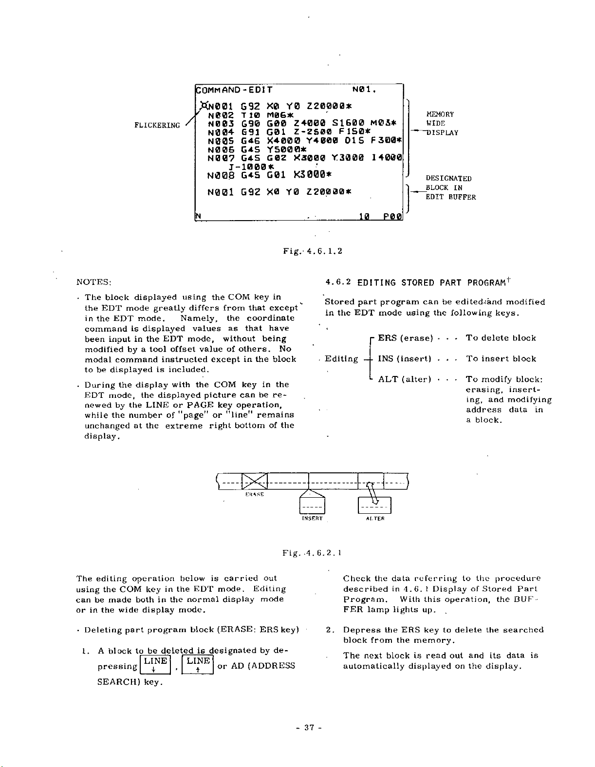
FLICKERING
COMMAND-EDIT
XN001
N002
'
/
N003
N004
N00S
N00&
N0
07
J-1000*
N008
N001
G92
T
10
G90
G91
G46
G4S
G4S
G4S
G92
X0
M06*
G00
G01
X4000
500
Y
G0Z
G01
X0
0
Y
4000
Z
Z-ZS00
Y
0*
*3000
K3000*
0
Y
Z20000*
SJ.600
4
000
Y3000
Z20000*
N01
F1S0*
015
.
MCi*
300*
F
14000
MEMORY
WIDE
DISPLAY
DESIGNATED
BLOCK
IN
EDIT
BUFFER
NOTES:
The
•
the
the
in
command
been
modified
modal
be
to
During
•
EDT
newed
while
unchanged
display.
block
EDT
EDT
input
command
displayed
the
mode,
by
the
displayed
mode
mode.
is
displayed
in
a
by
display
the
the
number
at
greatly
the
tool
is
displayed
LINE
the
using
differs
Namely,
EDT
mode,
offset
instructed
included.
with
or
PAGE
"page"
of
extreme
N
values
value
the
picture
the
from
without
except
COM
key
or
right
COM
the
that
as
others.
of
in
key
can
operation,
"line"
bottom
in
key
that
except
coordinate
have
being
block
the
the
in
re¬
be
remains
of
tlUSE
No
the
Fig.'
7_
INSERT
4.6.
1.2
4.6.2
Stored
the
in
Editing
10
EDITING
part
EDT
-
-
—
L
%
ALTER
peg
program
mode
(erase)
ERS
(insert)
INS
(alter)
ALT
STORED
can
using
PART
be
the
-
.
PROGRAM1
editediand
following
To
•
-
delete
To
insert
To
modify
erasing,
ing,
address
a
block.
•
.
•
keys.
and
modified
block
block
block:
insert¬
modifying
data
in
The
using
can
or
Deleting
1.
editing
the
made
be
the
in
A
block
pressing
SEARCH)
operation
COM
bothinthe
wide
part
to
key
display
program
be
LINE
key.
below
the
in
mode.
deleted
EDT
normal
block
is
LINE
t
is
carried
mode.
display
(ERASE:
designated
AD
or
out
Editing
mode
ERS
de-
by
(ADDRESS
Fig.
key)
4,
37
-
6.2.
2.
-
1
Check
described
Program.
FER
lamp
Depress
block
from
The
next
automatically
the
data
in
lights
the
block
4.6.
With
ERS
the
displayed
referring
t
Display
this
up.
key
memory.
is
read
to
operation,
delete
to
out
the
on
of
and
the
Stored
the
display.
procedure
DUF¬
the
searched
its
data
Part
is
Page 40

FLICKERING
COMMAND
N0O1
N002
N003
„
N00<
#N00S
N006
N007
1-
N00S
N00S
DIT
-E
692
T
10
G
90
691
646
G4S
G4S
1000+
G45
G46
X0
M06*
GOO
601
X4000
Y
SB
02
G
1
G0
X
400
Y0
Z4B00
Z-ZS00
00*
X5000
X3000*
0
2
20000*
Y4000
Y4000
SI
Y
FI
DlS
3000
DlS
600
N0
SB*
1.
10
M03*
FS00*
14000
F30S*
PB0
-
'
—
Designate
block
deleted.
the
be
to
|
EHS
KEY:
|
FLIKER-
ING
block
N005
is
COMMAND-EDIT
N001
N002
N003
N004
RNB06
N007
N008
N009
N006
692
T
G90
G9
G4S
G4S
J-
1000*
G4S
Y-S000*
646
0
1
1
deleted
xe
M06*
600
G0
1
YSB00*
G02
GO
1
YSBB0*
Fig.
and
Y0
Z4000
Z-ZS00
XJ00B
X3O00*
4.
N0O6
Z20H00*
Y
6.2.
SI
2
is
600
F
1
3
000
designated
.
1
N0
M03*
50*
14000
10
PBQ
using
“
—
the
ERS
The
block
designated
deletion.
key.
to
after
be
38
-
Page 41
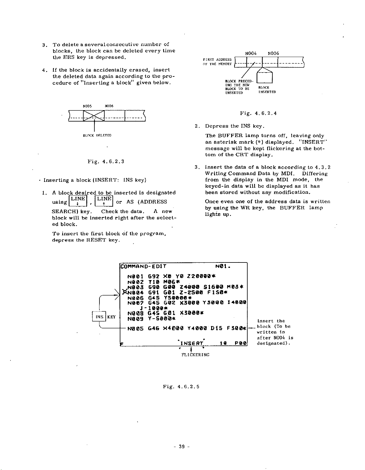
3.
4.
deleteaseveral
To
blocks,
ERS
the
the
block
If
the
deleted
cedure
of
block
the
is
key
is
data
’’inserting
consecutive
can
be
depressed.
accidentally
again
a
deleted
erased,
according
block”
number
given
every
to
insert
the
below.
of
time
pro¬
FIRST
OF
THE
ADDRESS
MEMORY
BLOCK
ING
BLOCK
INSERTED
[
PRECED¬
THE
TO
N004
NEW
BE
7x
BLOCK
INSERTED
N006
3
•
Inserting
1.
:
A
block
using
SEARCH)
block
block.
ed
insert
To
depress
a
LINE
will
NCOS
xi
BLOCK
block
desired
\
key.
be
the
RESET
the
OF.I.ETED
Fig.
4.
(INSERT:
to
LItNE
Check
inserted
first
INS~|
|
N006
6.
2.3
INS
inserted
be
AS
or
the
right
block
of
key.
COMMAND-EDIT
N001
N®
N003
&N004
N006
N007
—
N008
N009
N00S
KEY
s
key)
is
(ADDRESS
data.
after
the
program,
02
J
designated
A
new
select¬
the
692
0
T
1
M06*
G90
69
1
GAS
GAS
00
-
GAS
Y-S000*
G46
X0
Y0
G00
G01
YSO000*
602
A
0
G
1
X4000
*
'
2.
Depress
The
an
message
tom
Insert
3.
Writing
from
keyed-in
been
Once
by
lights
Z
20000*
Z4000
Z-ZS00
X3000
X3000*
T
1600
S
F
Y5000
000
4
D
INSERT*
FLICKERING
*
BUFFER
asterisk
of
the
stored
even
using
N01.
S0*
1
S
1
10
the
will
the
the
Command
display
data
the
up.
MBS*
14000
F300*
P00
Fig.
INS
mark
CRT
data
without
one
WR
lamp
be
display.
of
will
of
,
6.2.4
4.
key.
turns
(*)
displayed.
kept
a
block
Data
in
the
be
displayed
any
the
address
key,
Insert
block
written
after
designated)
off,
flickering
according
by
MDI.
MDI
modification.
BUFFER
the
the
(To
be
In
N004
leaving
at
mode,
as
data
is
.
only
"INSERT"
the
bot¬
to
4.3.2
Differing
the
it
has
is
written
lamp
Fig.
6.
4.
2.
5
-
-
39
Page 42

4.7
PUNCHOUT
OPERATION’
4.7.1
The
stored
tapes.
JAPE
part
in
The
provided.
puncher
Tape
FACIT
Type
Punching
Dimensions:
PUNCHER
program
the
memory
tape
4070
Speed:
432(W)
and/or
puncher
75
ch/sec
x
can
should
220(D)
YASNAC
the
be
C3
tool
offset
punched
separately
be
198(H)
x
SlPN
/
/
CONNECTOR
y.uf
iif;~
V-ft
out
SPRING
51
o
JUNCTION
(TYPE
TYPE
I
values
in
mm
LOCK
OR
5
H
DB19678-?)
DB-25P
n
SHELL
PLATE:
BELOW
0110278
io
£5}
'cT
Fig.
CÿFACIT
\
CONNECTOR
TYPE
DB-2S
TYP1
0
1
1.
7.
4.
CONNECTIONS
CONTROL.
AND
YASNAC
PIN
NO.
1
2
3
4
5
6
7
8
9
10
1
1
12
20
21
25
Chi
Ch2
Ch3
Ch4
Ch5
Ch6
Ch7
Ch8
Ch9
SD
PI
PR
Err.
TL
0V
BETWEEN
THE
PUNCHER
PIN
1
THE
FACIT
i
2
3
4
5
6
7
8
9
10
1
1
12
20
21
25
NO.
Fig.
LOCK
RELEASED
7.
4.
YASNAC
1.2
E/JCKF.D
CABLE
FROM
V
'-i
CONNECTED
BY
TO
CONNECTOR
FACIT
YASNAC
42
-
-
Page 43
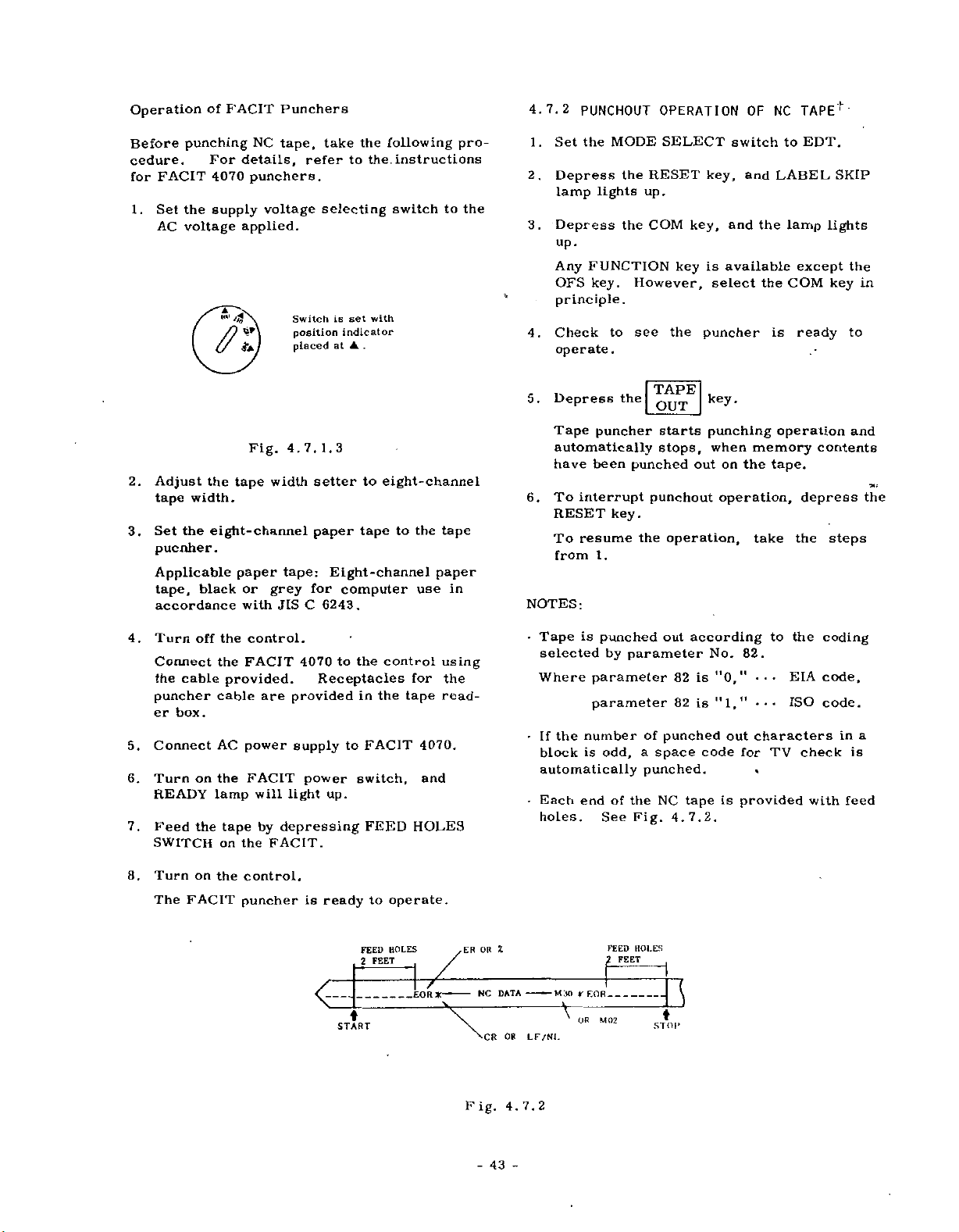
Operation
of
FACIT
Punchers
4.7.2
PUNCHOUT
OPERATION
OF
NC
TAPEf'
Before
cedure.
FACIT
for
Set
1.
AC
2.
Adjust
tape
Set
3.
pucnher.
Applicable
tape,
accordance
punching
For
4070
the
supply
voltage
n
the
width.
the
eight-channel
black
NC
details,
punchers.
voltage
applied.
Fig.
tape
paper
or
with
tape,
4.
width
tape:
grey
JIS
take
refer
selecting
Switch
position
placed
7.
1.
setter
paper
Eight-channel
for
C
6243.
the
to
is
set
indicator
at
.
3
to
tape
computer
following
instructions
the.
switch
with
eight-channel
the
to
use
pro¬
to
tape
paper
in
the
Set
1.
2.
Depress
lamp
Depress
3.
up.
Any
OFS
principle.
Check
4.
operate
Depress
5.
Tape
automatically
have
To
6.
RESET
To
from
NOTES:
MODE
the
the
lights
the
FUNCTION
key.
to
.
the
puncher
been
interrupt
key.
resume
l.
SELECT
RESET
up,
COM
However,
see
the
TAPE
OUT
starts
stops,
punched
punchout
the
operation,
key
key,
key,
is
select
puncher
key.
punching
when
out
switch
and
and
the
available
the
memory
the
on
operation,
take
to
EDT.
LABEL
lamp
except
COM
is
ready
operation
tape.
depress
the
SKIP
lights
the
key
to
and
contents
steps
in
the
4.
5.
6.
7.
8.
Turn
Connect
cable
the
puncher
er
box.
Connect
Turn
READY
Feed
SWITCH
Turn
The
FACIT
off
on
the
on
the
FACIT
the
provided.
cable
AC
power
the
lamp
tape
the
on
the
control.
puncher
control.
are
FACIT
will
by
FACIT.
4070
Receptacles
provided
supply
power
light
up.
depressing
is
ready
<
START
to
the
in
to
switch,
FEED
2
control
the
FACIT
FEED
to
operate.
HOLES
FEET
for
tape
4070.
and
HOLES
/
EOR
using
the
read¬
-
•
•
•
i
ER
OR
NC
DATA
-
OR
CR
LF/NI.
is
Tape
selected
Where
If
block
the
punched
by
parameter
parameter
number
is
odd,
automatically
endofthe
Each
holes.
M30
—
See
1
ROR
*
\
M02
OR
parameter
FEED
FEET
out
of
punched
a
space
punched.
NC
Fig.
HOLES
STOP
according
82
is
82
is
tape
4.7.2.
]
No.
"0,"
"1,"
code
out
is
to
82.
•
•
•••
characters
for
TV
provided
the
EIA
ISO
coding
code,
check
with
code.
in
a
is
feed
Fig.
4.7.2
-
43
-
Page 44

the
If
•
FACIT
FACIT
punching
trouble
and
the
above
•
During
message
tape
first
Error
lights
4070,
cause
.
punch
lamp
up
the
operation.
such
over,
following
step
out
"TAPE
on
due
control
start
operation
OUT"
the
to
After
as
excessive
punching
procedures
flickers.
control
the
trouble
automatically
elimination
operation
using
panel
tape
described
TAPE
OUT
of
the
in
stops
of
tension
from
the
the
key,
.
If
lights
the
ation.
such
start
following
ation
•
During
message
the
control
as
Error
due
up
After
excessive
punching
procedures
of
NC
punch
"TAPE
on
lamp
the
to
trouble
automatically
elimination
tape
operation
Tape.
out
operation
OUT"
the
tension
in
flickers.
FACIT
stops
from
4.7.2
in
of
using
control
the
FACIT
punching
the
trouble
and
the
Punchout
TAPE
OUT
tape
first
panel
4070,
oper¬
cause
over,
stop
Oper¬
key
4-7.3
Set
1.
Depress
2.
lamp
Depress
3.
If
is
Check
4.
to
Depress
5.
The
when
To
6.
RESET
To
1.
NOTES:
•
Tape
selected
When
code
•
the
If
block
automatically
is
tape
PUNCHOUT
the
MODE
the
lights
the
the
other
selected,
see
to
operate.
the
puncher
the
offset
suspend
key.
resume
is
punched
by
parameter
is
selected
number
is
odd,
is
provided
OF
SELECT
RESET
up.
OFS
FUNCTION
part
that
TAPE
OUT
starts
value
the
punch
the
operation,
out
parameter
No.
and
of
punched
a
space
punched.
with
TOOL
key,
key,
program
the
tape
key
and
has
operation,
according
No.
"82"
1
,
"
"
character
feed
OFFSET
switch
and
LABEL
the
and
key
than
is
puncher
with
lamp
punched
OFS
automatically
been
punched
take
to
"82."
set
is
ISO
code.
characters
out
for
Each
end
holes.
VALUE
to
EDT.
the
depress
the
the
at
"0,"
TV
Fig.
lights
OFS
is
key
step
coding
the
of
4.7.2.
SKIP
out.
ready
held
stops
off.
from
EIA
in
check
key
a
NC
up.
the
in.
4.7.4
4.8
4.8.1
To
with
1.
2.
Select
Depress
Selection
•
-
Depress
tape
check
Set
Depress
Memory
OUTLINE
PUNCHING
EDT
X
X
Any
key
OFS
key
X
and
COLLATING
AND
OFFSET
COLLATING
whether
tape
NC
MODE
the
illuminated.
is
mode.
RESET
of
FUNCTION
other
for
TAPE
the
offset
OF
contents,
RESET
the
is
rewound
OF
OPERATIONÿ
key.
than
offset
OUT
value
Fig.
STORED
TAPE
OFS
value
key
stored
4.7.4
DATA
VALUE'
OF
STORED
the
memory
proceed
SELECT
key.
and
STORING
keys.
for
key
stored
for
punching
tape.
PROGRAM
PROGRAM
contents
as
switch
LABEL
NC
tape.
follows:
the
to
SKIP
AND
Tape.
NC
f
agree
EDT.
lamp
is
.C
44
-
-
Page 45

Depress
3.
light
Set
4.
Be
Depress
5.
The
ory
Whenitreads
cally
If
6.
disagreement
INPUT
reader
NOTES:
•
Collation
tion.
tab,
lating
the
If
*
med
data
INPUT
During
key,
ering
the
up.
the
NC
sure
that
the
reader
tape
contents
stops.
ERROR
stops.
is
Disregarded
and
ALL
operation.
stored
because
ERROR
collating
"TAPE
the
at
COM
tape
LABEL
TAPE
are
made
MARK
data
lamp
CHK"
bottom
to
CHK
starts
collated
rewind
with
lamp
Alarm
only
characters
different
is
of
the
of
message
of
key,
the
SKIP
key.
on
are
omitted
lights
NC
the
and
tape
lamp
reading,
with
stop
NC
lights
code
significant
ignored
up.
tape
CRT
the
reader.
code,
tape
up
"18''
such
from
leading
using
will
display.
lamp
remains
the
the
it
is
and
is
during
program¬
be
will
mem¬
data.
tape
automati¬
detected,
tape
displayed.
informa¬
as
space,
zero,
TAPE
CHK
flick¬
kept
on.
col¬
4.8.2
To
check
offset
with
follows
1.
Set
2.
Depress
lamp
3.
Depress
Set
4.
Be
5.
Depress
Tape
contents
automatically
is
If
6.
ed,
reader
NOTE:
control
COLLATING
whether
value
!
the
MODE
the
go
will
the
source
the
that
sure
the
reader
are
encountered.
disagreement
INPUT
Tool
is
ERROR
stops.
offset
ignored,
OF
the
stored
SELECT
RESET
on.
OFS
tape
LABEL
TAPE
CHK
starts
collated
stops
with
Alarm
number
if
TOOL
memory
in
tape,
switch
key,
and
key,
the
to
SKIP
key
with
reading,
with
when
the
tape
lamp
code
not
commanded
OFFSET
contents
proceed
to
and
LABEL
it
will
tape
reader.
remains
lamp
OFS
and
the
tape
rewind
dataisdetect¬
lights
"16"
effective
in
VALUES
agree
the
be
on.
key
memory
data,
stop
and
up
is
displayed.
in
tape.
as
EDT.
SKIP
held
code
on.
in.
if
tape
the
45
-
-
Page 46

4.9
SUMMARY
OF
OPERATION
IN
EDT
I
_
I
fOLLATlOfl.
AT
MODE'
STORAGE
FROM
TAPE
NUMBER
AT
"00"
NUMBER
OPERATOR’S
PANEL
READOUT
MEMJRY
-
_
|
%2U
Fig.
Table
WRITE
EDIT
4.9.
4.9.1
(EOB
key)
,
(ERS
INS,
PUNCHOUT
AT
NUMBER
"61"
1
ALT
keys)
4.10
LEADSCREW
"YASNAC
See
(TOE-C843-5'
Storing
Storing
Punchout
Punthout
Collating
Collating
Readout
Storing
DATA
Editing
ERROR
3000G
30}
separately
data
NC
of
of
of
of
of
stored
value
stored
tool
stored
stored
program
offset
part
keyboard
stored
part
COMPENSATION*
OPERATOR'S
provided.
tape
from
from
program
offset
program
offset
part
through
program
MANUAL1
tape
value
values
program
Function
Key
COM
OFS
COM
OFS
COM
OFS
COM
COM
COM
4.11
See
(TOE-C843-5*
STROKE
"YASNAC
Keys
TAPE
IN
TPAE
OUT
TAPE
CHK
CHECK’
3000G
30)
for
Starting
key
key
key
OPERATOR'S
separately
MANUAL/'
provided.
-
46
-
Page 47

APPENDIX-1
Decimal
Decimal
the
With
acter
can
point
Shown
using
decimal
A
parameter
be
will
becomes
of
G94
5
6
2+
—
.
of
point
control
display,
below
a
decimal
point.
Address
characters
X.
I,
(G04)
distance
handled
or
X
Y
F
(in
F
F
(in
F
Dwell
Handling
1.
•
Unit
Distance
Feedrate
Time
NOTE:
a
by
data
which
tion
EXAMPLE:
X
15.
Y20.
(G94)
F25.
G95F.
G04P1
input.
be
Y,
K,
J,
F
is
effective
G95.t
15.
20.
25.
the
4.0)
0.20
the
2.2)
Point
input
equipped
a
is
the
point
a
Z,
R
P
unit
effective.
in
(MM)
000
500
0
mm/min
case
mm/rev
case
000
l.
number
address
and
At
or
At
min,
(mm/rev
At
as
terms
by
mm
mm
of
of
sec.
Input
with
having
data
the
Decimal
position
a
position
"inch.
a
position
or
"
a
position
currently
A
decimal
ofafeedrate
means
or
X
or
Y
or
F
{in
F
or
F
(in
F
CRT
the
a
decimal
capable
position
point
"mm"
of
"
of
"mm/
"inch/min,
inch/rev)t
or
of
"sec."
designated
point
a
designa¬
of
(INCH)
15.0000
20.5000
6
25.
inch/min
the
case
1)
3.
200
0.
inch/rev
case
the
3)
1.
char¬
of
of
unit
inch
inch
a
•
A
number
via
a
with
punched
tape
decimal
and/or
point
the
can
NC
be
input
operator's
panel.
•
Input
from
a
punched
tape:
TAPE
(or
MEM)
operation
•
Input
or
EDIT
from
the
writing-in
NC
operator's
panel:
MDI
NOTES:
trailing
a
The
omitted
attention
mistake,
cimal
mistake.
When
•
keying
writing
suffixed
crement
on
the
"
While,
no
trailing
decimal
as
ory
operation,
by
processed
Combination
•
no
decimal
Example:
•
Whenever
smaller
structed,
increment
input
zeros
use
by
should
so
point
happens
operation,
corresponding
currently
CRT
display.
with
the
zeros
point
has
it
the
point
X125.4Y
a
number
than
the
(zeros
of
decimal
be
given,
as
far
a
in
decimal
designated,
writing
will
will
data
keyed
been
trailing
throughout
of
the
the
decimal
data
least
numerals
designated
the
data
to
be
the
trailing
to
operation
be
be
in.
zeros
the
can
1000
containing
input
smaller
suffixed)
to
be
point.
as
it
concerns,
keyed
point
the
least
and
displayed,
stored
During
will
operation.
point
be
made.
*
the
increment
will
be
Sufficient
causes
or
in
data
zeros
input
displayed
for
into
the
be
data
numerals
than
the
disregarded
can
great
a
if
not
MDI
by
will
editing
and
the
mem¬
MEM
properly
and
the
in¬
is
least
be
de¬
by
be
in¬
the
EXAMPLE:
Least
Input
designated
of
12.34
X
of
•
Be
address
except
will
may
sure
be
not
0.01
56
never
data
the
for
disregarded,
be
made
operation.
increment
mm
0.001
to
use
as
such
ones
during
input
—
inch
a
decimal
M,
S,
specified.
however,
an
«ÿ
X
X
T
address
Effective
data
12.34
345
12.
point
and
B
Generally,
concurrence
search
mm
inch
to
codes,
all
it
47
-
-
Page 48
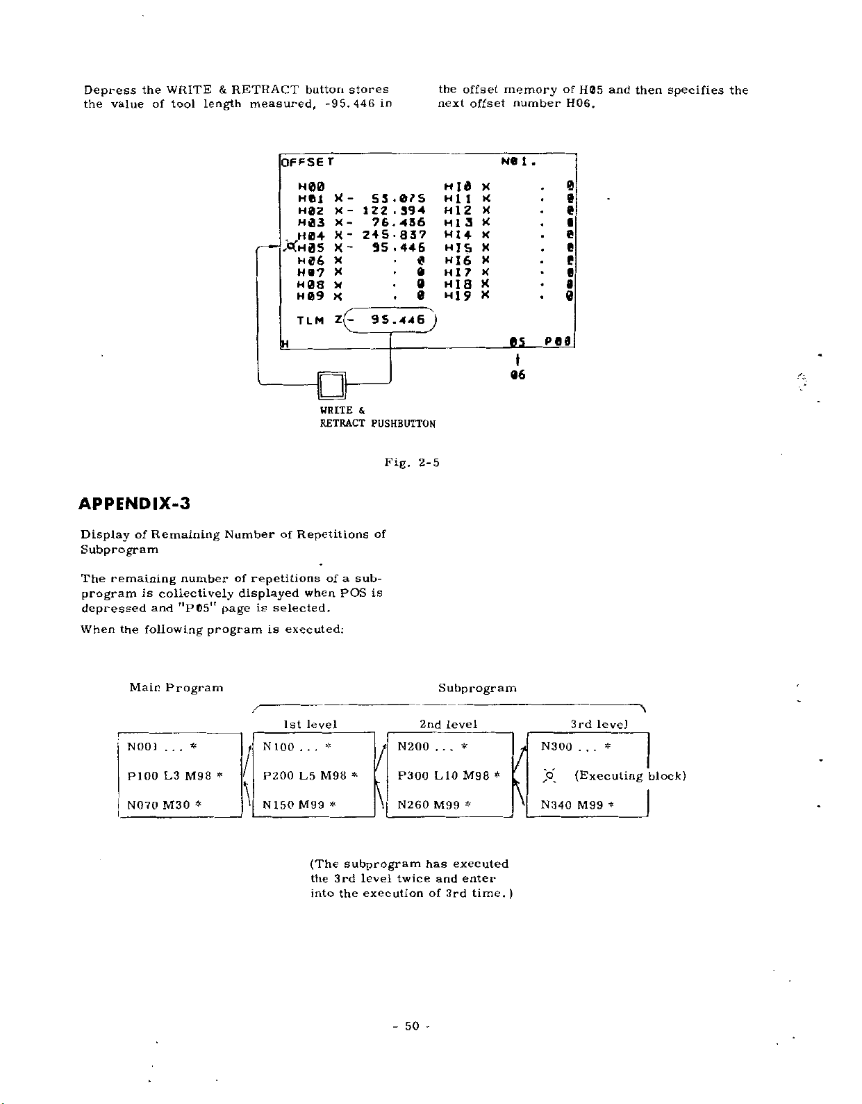
Depress
the
value
the
WRITE
of
tool
&
length
RETRACT
measured,
button
OFFSE
H00
H01
H0Z
H03
H04
.
XH05
H07
H08
H09
TLM
stores
-95.446
r
X
-
X
-
X
-
-
x
-
X
X
X
x
X
z(-
WRITE
RETRACT
in
55
.075
.
Z
1
394
2
.
436
76
837
S
24
.446
35
9
S
446
.
&
PUSHBUTTON
Fig.
0
0
0
0
2-5
J
the
next
H
H
H12
HI
H14
HJS
HI6
H
HI
HI
offset
I
1
1
9
offset
0
1
a
7
a
X
X
X
X
X
X
X
X
X
X
memory
number
N0
.
1
BS
06
*
of
H05
H06.
and
then
specifies
the
0
9
9
e
9
9
9
9
0
P
69
APPENDIX-3
of
remaining
is
the
following
Main
N001
P100
N070
Remaining
collectively
and
Program
.
.
L3
M30
Display
Subprogram
The
program
depressed
When
number
"PG5”
.
*
M98
*
Number
of
displayed
page
program
*
repetitions
is
selected.
is
N
100
P200
\
N
150
of
Repetitions
when
executed:
level
1st
.
.
.
L5
M99
(The
the
into
a
of
POS
*
M98
*
subprogram
3rd
the
of
sub¬
is
/
*
\
level
execution
N200
P300
N260
twice
Subprogram
level
2nd
.
.
.
1
L
0
M99
has
executed
and
3rd
of
*
M98
*
enter
time.)
3rd
level
N300
.
.
.
*
/
*
\
'
"
N340
(Executing
M99
block)
*
50
-
-
Page 49

as
number
follows.
remaining
The
displayed
i
of
repetitions
SUB
NEST
0
1
02
03
PRO.
Subprogram
be
will
NESTING
LOOP
SEQ.
NO
0100
0200
0300
sequence
-
-----
level
(The
Fig.
3-1
COUNT.
number
limit
N0
-
1
2S
is
.
3
S
S
POSi
Remaining
subprogram
of
8.)
Means
number
8
is
current
number
start
remaining
the
repetitions
of
including
executing
repetitions
of
the
one.
Precautions
The
remaining
that
the
current
•
When
the
repetitions
data
M98
will
M98.
the
be
display
program
are
be
displayed
said
the
the
When
•
and
ber
cannot
whether
or
APPENDIX-4
Others
The
proved
The
1.
G
30
MANUAL"
•
LED
An
restrictions
are
control
13)
the
in
restriction
and
31
and
numeral
input
neglected.
with
following
helix
of
error
number
execution'
on
on
the
copy
mixedly
the
from
remaining
CRT
character
ofRof
cutting
"YASNAC
TOE-C843-5-
display:
occurs
of
R
(rapid
of
repetetion
is
a
lev.el
level
G25
used,
the
by
display
number
functions.
circular
(G14,
3000G
30.
when
traverse
final.
is
completed,
deleted.
is
is
used
remaining
the
same
means.
of
"P05"
due
is
display
cutting
G15).
OPERATOR'S
)
the
following
l"
"
or
G25
G25
to
is
(Seepages
section)
means
num¬
It
im¬
(G12,
•
CRT
R
error
restrictions
Subprogram
2.
(G73,
76
AL"
•
LED
The
M98
dress
address
(See
3000G
5-
•
CRT
The
be
the
G
12,
15
G
14,
character
13
G
G
designation
does
not
G80
G76,
of
"YASNAC
TOE
-C
numeral
address
.
L.
P
..
with
P
for
P
the
EXAMPLE
OPERATOR'S
)
30.
character
address
reprogrammed.
canned
cycles
display:
is
disregarded
occur
neglected.
are
designation
toG89).
3000G
843
-5*
display:
must
P
is
.
.
*
destroys
M98
designation
display:
for
P
is
<
|R
0
<
|R
0
even
in
OPERATOR'S
)
30.
be
reprogrammed
given,
of
page
MANUAL"
dwell
is
(Address
retained.
(D)
-
(D)|
-
and
if
the
canned
(See
because
the
dwell
of
76
not
<
|I
|
<
K
|
an
above
cycles
pages
contents
"YASNAC
of
TOE-C843-
required
for
P
)
-
-
input
75
MANU¬
the
time.
dwell
(D)
(D)
|
|
and
when
ad¬
of
to
in
51
-
Page 50

Compensation
3.
solute
78
AL"
•
LED
When
position
point
Therefore,
each
Example
•
CRT
Cancel
the
to
G40
zero
Example
(When
execution
meral
zero
"YASNAC
of
TOE
numeral
G92
is
tool
N001
N002
character
the
specified
.
X.
point.
N001
N002
N003
G92
display
point
C843-5-30.
-
is
offset
set
by
G92
offset
G43
G92
*
The
tool
.
Y.
.
G43
G43
G92
*
Offset
Offset
=
(Z
is
is
the
cancel
(092).
3000G
display:
executed
A
or
B,
adding
must
cancelled.
is
XO
HOI
X1000
offset
*
X
is
display:
position
axis
by
and
.
*
H01
XO
H02
Z0
X1000
G40
1000
X
axis
to
axis
to
Z
200)
commanded
same
)
.
on
programming
(See
OPERATOR'S
)
the
mode
in
absolute
the
offset
tool
commanded
be
1
100
still
offsets
the
(HOI
effective.
command
the
set
(H01
(H02
*
=
then
*
*
*
is
cancelled.
is
effective.
without
with
that
pages
value.
A
G40,
of
77
MANU¬
tool
of
zero
after
100)
=
and
B
of
absolute
100)
=
200)
=
LED
of
and
the
nu¬
ab¬
only
G92
Axis
4.
•
LED
Axis
•
CRT
When
ping,
with
5.
Rapid
of
TOE
LED
Override
rapid
•
CRT
0%
rate
Optional
6.
Respectively
can
block
programming
input
skipped.
those
usable
the
interlock
numeral
interlock
character
interlock
the
feed
the
interlock
traverse
"YASNAC
3-
84
-C
numeral
of
traverse
character
cannot
set
by
Setting
block
be
set
skip
signal
ordinal
of
number
machine
in
display:
is
3000G
30.
5-
display:
100%,
be
used.
the
parameter
unit:
skip
independent
to
up
or
"/•'
and
is
on,
The
precautions
tool
tapping
is
not
display:
input
stopped
released.
rate
override.
OPERATOR'S
)
50%,
rate
can
display:
Instead
"l"
B
8
other
"/l."
when
the
optional
of
optional
builder's
(G84)
in
effect
is
on,
and
25%
be
-
7.5
(option)
than
Use
the
specified
block
during
even
during
is
restarted
(See
MANUAL"
and
0%
set.
of
the
it,
01
is
used.
mm/min
optional
ordinal
"/2"
corresponding
block
are
the
skip.
skips,
block
manual.
page
of
block
to
same
tapping.
tap¬
128
the
feed-
skip
optional
'79"
is
with
For
see
in
the
-
52
-
Page 51

i
\
t
I
I
Page 52

i
I
",
/
YASKAWA
TOKYO
Phone
Telex
OFFICE
(03)
222-2273YASKWA
Ohtemachi
284-91
1
Electric
Cable
1
J
Bldg.,
address
Mfg.
Chiyodaku,
YASKAWAMOTOR
Tokyo.
Co.,
Japan
100
TOKYO
Ltd.
fl
*
V
0.7TA
Printed
in
Japan
80-8
 Loading...