

Page 1
For GPD515 / G5 Adjustable Frequency Drives
Digital Follower (Velocity)
FLASH Memory Software Option (S11103)
Part Number: GPD515C-ZZZZ-CS007
With this factory-installed FLASH software, the
GPD515 has the ability to precisely follow the
speed of a master encoder or drive. The
speed / frequency ratio between the master
and the follower are infinitely adjustable.
This document is an addendum to Technical
Manual TM4515, listing the effect of this
software on the parameters in the drive and
function descriptions in the manual.
(1)
Specifications:
• Requires PG-W2 (DS014) card to function
• Available for all GPD515 drives
• 0.001 Hz Resolution
• Accepts Only Quadrature/Line Driver
Signals
• Accepts virtually any encoder resolution
• Bi-directional (Selectable)
• “Draw” adjustable from –99.99% to
+99.99%
• Ratio and “Draw” adjustable via:
Digital Operator
Serial Communications or
Analog Signal (0 – 10V or 4 – 20 mA)
• Control Modes: Open Loop Vector, Flux
Vector & V/f
• Serial Communications: Modbus RTU
DeviceNet, Modbus Plus & Profibus
(1)
ZZZZ refers to the base Model Number of the drive in which the software is installed.
Rel. 09/15/2000 Page 1 of 13 Doc. No. 02Y00025-0423
Page 2

1.0 Wiring
Wire the incoming power, motor, accessories and control wiring as specified in the GPD515 Technical Manual
TM4515.
If there is an encoder on the motor that this drive is running, wire that encoder to terminals 1 through 9 according to
the PG-W2 instruction sheet (02Y025-0397).
The master encoder (or pulse reference source) should be wired to terminals 10 thru 16 according to the PG-W2
instruction sheet (02Y025-0397).
NOTE: The +12V supply on the PG-W2 card is capable of only 200mA, be sure not to overload it.
2.0 I/O Definitions
2.1 New Multi-Function Digital Input Settings
For Parameters H1-01 through H1-06.
Addition to Table 5-2 Multi-Function Input Terminal Data Settings (Section 5.32)
Data Function Description Availability
80
81
(2)
GPD515 Technical Manual TM4515.
Pulse B w/ N.O.
Pulse B w/ N.C.
Closed = Pulse monitor will output speed feedback
(Terminals 3 thru 8)
Open = Pulse monitor will output master reference
pulses (Terminals 10 thru 15)
Closed = Pulse monitor will output master reference
pulses (Terminals 10 thru 15)
Open = Pulse monitor will output speed feedback
(Terminals 3 thru 8)
(2)
0 1 2 3
X X X
X X X
2.2 New Multi-Function Digital Output Settings
For Parameters F5-01 and F5-02, and H2-01 through H2-03.
None.
2.3 New Multi-Function Analog Input Settings
For Parameters H3-05 and H3-09.
None.
2.4 New Multi-Function Analog Output Settings
For Parameters H4-01 and H4-04.
None.
X
X
Rel. 09/15/2000 Page 2 of 13 Doc. No. 02Y00025-0423
Page 3

3.0 Startup Procedure
1. Perform the appropriate procedure for start-up using Section 2.2 of the GPD515 Technical manual. Most
applications with this software utilize the flux-vector control method, which is highlighted in Section 2.2b.
2. Set the reference source to “Pulse Reference” (b1-01 = 5).
3. Set the “Following Method” as desired (see Figure 1). With a setting of “1-direction” (P2-01 = 0) and the master
running forward, the follower motor will run forward. When the master runs in reverse, the follower will stay at
zero speed. With a setting of “Bi-directional” (P2-01 = 1) the follower will run whichever direction the master is
running. A setting of “Absolute” (P2-01 = 2) will result in the follower running forward regardless of the master’s
direction.
Figure 1: Parameter P2-01 Description
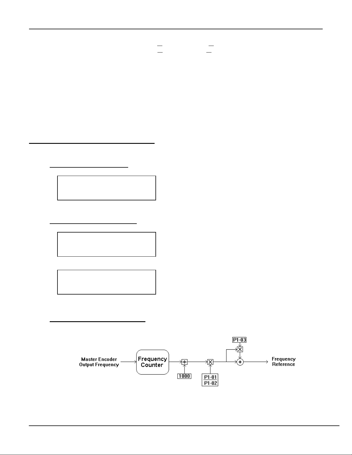
4. Parameters P1-01, P1-02, and P1-03 can be calculated and set in many ways. Figure 2 illustrates the effect
those parameters will have on the follower’s frequency reference. When it is desired to have the follower motor
shaft turn at exactly the same speed as the master encoder, use Table 1 below.
Table 1: Common Settings for Parameters P1-01 thru P1-03
Master
Encoder PPR
1024 2 125 128 0.00
2048 2 125 256 0.00
2500 2 2 5 0.00
1024 4 125 64 0.00
2048 4 125 128 0.00
2500 4 4 5 0.00
10000 4 1 5 0.00
1024 6 375 128 0.00
2048 6 375 256 0.00
2500 6 6 5 0.00
10000 6 3 10 0.00
• If the above table does not include your specific setup, use the following formula to determine the settings of
P1-01, P1-02 & P1-03.
P1-01 = Number of Motor Poles (Follower Motor) * 500
P1-02 = Pulse Generator PPR (Master Encoder)
P1-03 = 0
If a ratio different from 1 : 1 is needed, use the following equation:
X : Y - Where X = Master Encoder Revolutions and Y = Follower Motor Revolutions
P1-01 = Number of Motor Poles (Follower Motor) * 500 * Y
P1-02 = Pulse Generator PPR (Master Encoder) * X
P1-03 = 0
5. Verify that the master reference encoder is working. Bring up parameter U1-01 on the digital operator by
pressing MENU then DATA/ENTER. When the master reference encoder is moving, a non-zero frequency
reference should show up here. If not, troubleshoot encoder wiring, or verify that P2-01 is not set to 0 (One
direction).
Follower
Motor Poles
P1-01
Setting
P1-02
Setting
P1-03
Setting
Rel. 09/15/2000 Page 3 of 13 Doc. No. 02Y00025-0423
Page 4
6. If the follower drive needs to run at a different speed, adjust one or more of the following parameters:
Follower is running too slow: Increase P1-01, or
Follower is running too fast: Decrease P1-01, or
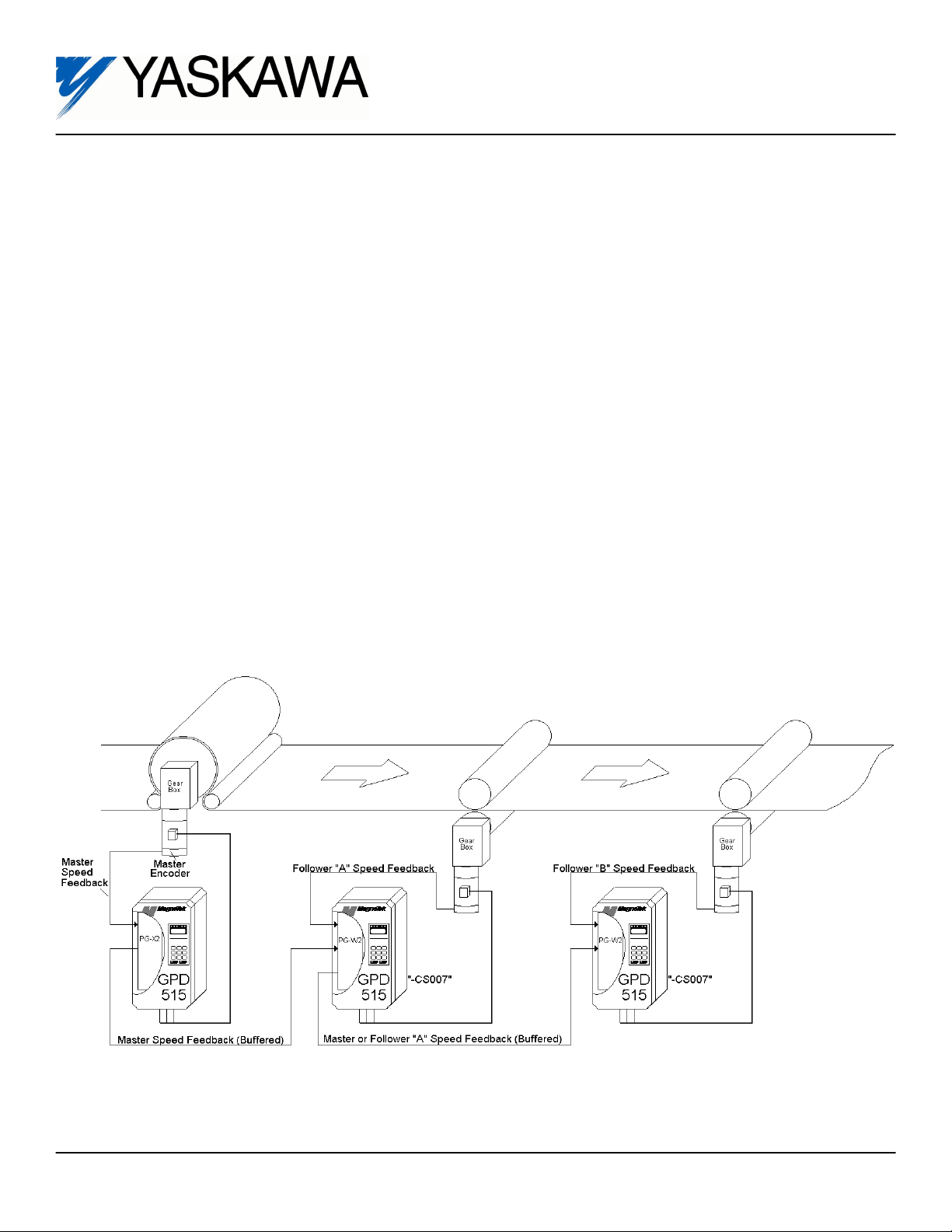
7. Optional Step: If desired, the pulse output from the PG-W2 card can be switched between the master
reference signal and the feedback signal by programming a Multi-Function Input Terminal (terminals 3 through
8, parameters H1-01 through H1-06) to a value of 80 or 81. Then a contact closure can switch between a
straight master/follower and a cascaded follower. Refer to the drawing on the page one of this instruction
manual. If no further programming is done, Follower “B” will follow the master reference encoder. If a multifunction input is programmed and selected in Follower “A”, Follower “B” will follow Follower “A” instead of the
master reference encoder.
8. Done.
Decrease P1-02, or set P1-03 to a positive number.
Increase P1-02, or set P1-03 to a Negative number.
4.0 Custom Software Parameters
4.1 New Program Group
Group P
Pulse Input
4.2 New Program Function
Function P1
Pulse Ratio
Function P2
Follow Options
4.3 New Program Parameters
Figure 2: Block Diagram – Frequency Reference
Rel. 09/15/2000 Page 4 of 13 Doc. No. 02Y00025-0423
Page 5

Gear Tooth 1
P1-01= 1
P1-01 Gear Tooth 1 A A A A
Setting Range: 0 to 10000
Factory Default: 1
Modbus Address: 0580H
This is the “Numerator” portion of the pulse ratio. (See Figure 2)
Gear Tooth 2
P1-02= 1
P1-03 Gear Tooth 1 A A A A
Setting Range: 0 to 10000
Factory Default: 1
Modbus Address: 0581H
This is the “Denominator” portion of the pulse ratio. (See Figure 2)
Ratio Setting
P1-03= 0.00
P1-03 Ratio Setting A A A A
Setting Range: -99.99 to +99.99
Factory Default: 0.00
Modbus Address: 0582H
Sets the amount of frequency reference increase or decrease (draw) as a percentage of the incoming reference.
(See Figure 2)
Rel. 09/15/2000 Page 5 of 13 Doc. No. 02Y00025-0423
Page 6

Follow Method
P2-01 = 0
P2-01 Follow Method A A A A
Setting Range: 0 to 2
Factory Default: 0
Modbus Address: 0590H
This parameter effects how the drive will react when the master pulse reference source or encoder changes
directions (fwd or rev).
Setting Description
0 One Direction
1 Bi-directional
2 Absolute Value
Rel. 09/15/2000 Page 6 of 13 Doc. No. 02Y00025-0423
Page 7

4.4 Modified Parameter(s)
Reference Source
b1-01 = 1
b1-01 Reference Source A A A A
Setting Range: 0 to 5
Factory Default: 1
Modbus Address: 0180H
This parameter determines from what source the frequency reference will come from. Added was a setting of “5 –
Pulse Reference”..
Setting Description
0 Operator
1 Terminals
2 Serial Com
3 Option PCB
4 EWS
5 Pulse Reference
5.0 New Monitors
None.
6.0 New Alarm and Fault Codes
None.
Rel. 09/15/2000 Page 7 of 13 Doc. No. 02Y00025-0423
Page 8

Appendix 1: Advanced Application Notes
Part 1: Web Process Line - 1 : 1 follower with a 5% draw
Step 1: Calculate the Frequency Ratio
GBf Pf dm
Where: dm = diameter of master roll
df = diameter of follower roll
PPRm = Master Reference Encoder pulses per revolution
GBf = Follower Gear Box ratio (motor RPM / roll RPM)
Pf = Motor poles, follower motor
GBm = Master Gear Box Ratio (motor RPM / roll RPM)
Note: If no gearbox is present, the gear box ratio is 1.
Rel. 09/15/2000 Page 8 of 13 Doc. No. 02Y00025-0423
FrequencyRatio
500( ) ( ) ( )
=
PPRm df GBm
()()()
Page 9

Step 2: Determine drive parameters P1-01 & P1-02
If Frequency Ratio ≥ 1
P1-01 = 10000
P1-02 = 10000 / Freq. Ratio
If Frequency Ratio < 1
P1-01 = Freq. Ratio * 10000
P1-02 = 10000
EXAMPLE:
On a paper machine, a nip roll (follower roll) has to follow master roll with a 5% fixed draw.
Nip (follower) roll diameter = df = 16.0”
Master roll diameter = dm = 34.078”
Master encoder pulses per revolution = PPRm = 1024
Gearbox between the follower motor and the follower will cause the motor shaft to turn
4.048 turns for one turn on the follower roll.
GBf = motor / roll = 4.048 / 1 = 4.048
Follower motor has 4 poles = Pf = 4
Gearbox between master motor and the master roll will cause the motor shaft to turn 7.5
turns for one turn of the master roll.
GBm = motor / roll = 7.5 / 1 = 7.5
FrequencyRatio ==
500 4 048 4 34 078
(. )()( . )
1024 16 0 7 5
()(.)(.)
2 245
.
Frequency Ratio is greater than 1, so:
P1-01 = 10000
P1-02 = 10000 / 2.245 = 4454 (rounded to nearest whole number)
P1-03 = 5.0% (to achieve the 5% fixed draw)
Rel. 09/15/2000 Page 9 of 13 Doc. No. 02Y00025-0423
Page 10

Rel. 09/15/2000 Page 10 of 13 Doc. No. 02Y00025-0423
output of the gear reduction corresponds to 1 widget.
(includes the PG-W2 option card). The follower machine has a 25:1 gear reduction connected to the motor . One turn of the
The follower machine has a standard 4-pole motor on it. This motor is connected to a GPD515 with the CS007 software option
Overview:
In the above drawing there is a machine where one section has to follow another with an exact speed match. The portion of
the machine that is the “master” has an encoder mounted to a portion of the machine that is moving at line speed, such as a
line shaft. The follower is connected to a GPD515 with the CS007 software option (which includes the PG-W2 option card).
Machine Description:
The line shaft of the machine will produce 1 widget per revolution. There is an encoder attached to this line shaft which is the
quadrature / line driver type with a separate power supply. It will produce 360 PPR (pulses per revolution). This encoder is
attached to the follower drive’s PG-W2 card on terminals 10-13 with the shield on terminal 16.
Part 2: Widget machine - 1 : 1 follower (detailed explanation)
Page 11

PG-W2 Theory Of Operation
The PG-W2 card is a dual input encoder card. One input into the PG-W2 card can be used as a
frequency reference (terminals 10 - 13). The other input can be used as a speed feedback (terminals
3 - 6). There is one +12V power supply (terminals 1 and 2) capable of 200mA. Typically this power
supply can only provide enough current to power one encoder.
The frequency coming into the PG-W2 on terminals 10 - 13 is processed internally to come up with a
frequency reference. First, the incoming frequency is divided by 1000. Then it is multiplied by
parameter P1-01 then divided by parameter P1-02. The ratio of P1-01 over P1-02 is called the
frequency ratio. It allows the incoming frequency to be scaled to any application. Parameter P1-03
will increase or decrease the frequency reference by a set percentage.
In order to figure out the correct settings of P1-01 and P1-02, the frequency ratio needs to be
determined. When determining the frequency ratio, several pieces of information are required:
reference encoder speed (at a particular line speed), encoder output frequency, follower motor speed
(at a particular line speed), number of motor poles for the follower and follower motor frequency.
Determining Frequency Ratio For The Above Example (circled numbers correspond to
areas in the above drawing)
Encoder Speed:
The encoder attached to the line shaft turns one revolution for every widget produced. Therefore if
the line is running at 65 widgets / minute, the encoder is turning at 65 RPM.
Encoder output frequency (fe):
The encoder produces 360 pulses per
revolution. The encoder is turning at
65 RPM.
fe
pulses
360 65 1
revolution
revolution pulses
min
*
60
min
390 390*
sec sec
Hz===
Motor Speed:
With a line speed of 65 widgets / minute, the output of the
gear reduction will be 65 RPM. The gear reduction is 25:1.
Motor Speed RPM RPM==65
25
1625*
1
Motor Frequency:
Motor speed is 1625 RPM and there are four motor
poles
motor poles motor RPM
fm
**
120
4 1625
120
.
54 17
Frequency Reference:
If the GPD515 is in Flux Vector mode, Open Loop Vector Mode, or V/f with PG mode, or V/f mode
with slip comp enabled, the drive will automatically compensate for slip in the follower motor.
Therefore, calculated motor frequency should equal frequency reference.
Hz
Frequency Reference after encoder output frequency has been divided by
1000. Encoder frequency = 390Hz
390
f
1000
039==.
Hz===
Hz3
Rel. 09/15/2000 Page 11 of 13 Doc. No. 02Y00025-0423
Page 12

For the sake of determining the frequency ratio, assume that parameter P1-03 is set to 0.00%.
This would make the frequency at the same as at .
Frequency Ratio:
With all of the above equations solved, the frequency ratio can now be determined. Ideally, P1-01
would equal the frequency at , and P1-02 would equal the frequency at , however, only whole
numbers can be entered into P1-01 and P1-02.
In order to solve this problem, multiply both frequencies by 10, 100, 1000, or 10000. Seek the
highest numbers possible without exceeding 10000.
Frequency at = 0.39Hz
Frequency at = 54.17Hz
Therefore:
P1-01 = 54.17Hz * 100 = 5417
Because the frequency at was multiplied by 100, the frequency at needs to be multiplied by
100 also.
P1-02 = 0.39Hz * 100 = 39
Enter these values into the drive.
Other Programming Considerations:
There are many parameters in the drive which will effect how closely the follower will track the
master. Below is a list of the most commonly used parameters with the PG-W2 option card.
Parameter Description
b1-01 Reference Source - This parameter should be set to a value of 5, which will force
the drive’s frequency reference to come from the PG-W2 option card. Other
reference sources can be used. See the GPD515 Technical manual TM4515.
C1-01 Acceleration Rate - To achieve maximum response from the follower, this
parameter needs to be set to a value lower (faster) than the maximum expected
rate of speed change. This parameter can be set all the way down to zero.
For more information, consult the GPD515 Technical manual TM4515.
C1-02 Deceleration Rate - Same considerations as Acceleration Rate.
C5-01 ASR Gain - The higher this number is set, the closer the follower will track, but if
this number is set too high, the follower will become unstable. This parameter will
only be available when in the Flux Vector or V/f w/PG feedback modes.
C5-02 Integral Time - The lower this number is set, the closer the follower will track, but
if this number is set too low, the follower can become unstable. This parameter
will only be available when in the Flux Vector or V/f w/PG feedback modes.
E1-04 Maximum Output Frequency - This parameter needs to be set to a high enough
value. Be careful not to exceed the motor manufacturer’s speed rating.
Rel. 09/15/2000 Page 12 of 13 Doc. No. 02Y00025-0423
Page 13

Part 3: Variable Ratio Using A Potentiometer & The PG-W2 card
Sometimes an application will
call for a variable ratio or
“draw” while using the PG-W2
card. For example: A follower
drive needs to have an exact
speed match plus an adjustable
0 - 5% overspeed.
Parameters P1-01 & P1-02
should be calculated as
described in Part 2 of this
document. Parameter P1-03
should be left at 0.0%.
An 0 - 10V analog signal,
brought in on terminal 16, will
be scaled to represent a 0 - 5%
overspeed. This is
accomplished using the FGAIN
function, and the analog input
bias and gain functions.
The schematic on the left
shows the correct wiring for the
analog input (terminal 16) using
a potentiometer.
Parameter number H3-05
needs to be set to a “1” which
sets terminal 16 to the FGAIN
function.
Parameter numbers H3-06 & H3-07 (terminal 16 gain & bias)
need to be adjusted so that 0V on terminal 16 results in 100%
gain (1 : 1) and 10V on terminal 16 results in 105% gain (1 : 1.05).
In order to set this up, parameter H3-06 needs to be set to the
maximum amount of draw required plus 100% (5% + 100% =
105%
of draw required plus 100% (0% + 100% = 100%
). Parameter H3-07 needs to be set to the minimum amount
).
Rel. 09/15/2000 Page 13 of 13 Doc. No. 02Y00025-0423
 Loading...