

Page 1

ruC
In»t
TOE-C843
May,
i
oni
1981
-3.22
YASNAC
WITH
2000
CRT
OPERATOR’S
CHARACTER
MANUAL
G
DISPLAY
If,;
YASKAWA
Electric
Mfg.
Co.,
Ltd.
Page 2

INTRODUCTION
YASNAC
(henceforth
specifically
CNC
The
CRT
positions,
several
PRIFACI
This
manual
handling
display.
are
enumerated
reference
2000G
called
display
tool
blocks
YASNAC
Descriptions
to
with
CRT
designed
prominently
offset
of
these
describes
2000G
in
Chapter
YASNAC
CRT
display)
data,
data
the
of
2000G
character
for
lathe
shows
etc.
can
instructions
with
NC
operator's
for
4
display
is
the
latest
applications.
commands,
In
addition,
collectively
be
CRT
character
panel
easy
cross-
OPERATOR'S
for
displayed.
operator
as
data,
keyboard
type
more
touch
resulting
MANUAL
For
in
instructions
this
ATOR’S
This
convenience
weil
surface,
in
increased
provided
manual,
MANUAL
facilitates
as
checking.
combines
and
separately.
other
to
refer
(TOE-C843-5-20).
writing,
in
modern
simplifies
reliability.
than
YASNAC
recognition
modifying
adoption
The
the
2000C
and
of
styling
the
with
operation,
descriptions
OPER¬
.
the
flat
Page 3

NC
4.
OPERATOR'S
PANEL
WITH
CHARACTER
CRT
DISPLAY
2
4.
4.2
4.3
1
PUSHBUTTONS,
1
1.
4.
4.1.2
4.1.3
4.
1.4
4.
1.5
1.6
4.
4.1.7
4.1.8
1.9
4.
10
4.1.
11
1.
4.
4.
12
1.
13
1.
4.
1.
4.
14
4.1.15
4.1.16
POWER
4.2.
I
4.2.2
4.2.3
DISPLAY
4.3.1
4.3.2
4.3.3
4.3.4
4.3.5
4.3.6
4.3.7
4.3.8
4.3.9
4.3.10
4.3.11
12
4.3.
13
4.3.
4.3.14
15
4.3.
16
4.3.
Lamps
Select
Keys
•
Key*
Key.
Key
SEARCH)
(
AND
LAMPS
Pushbutton*
Display
Knob
Keys
• •
•
(
!PA°el
(
35
Key
ERS
INS
.
•
PS5>
S
Key
ALT
KEYS,
Power
CRT
BRIGHT
ON/OFF
Character
Indicating
FUNCTION
ADDRESS
DATA
PACE
LINE
ORG
WR
AS
Editing
Keys
Select
Select
(ORIGIN)
(WRITE)
(ADDRESS
Kevs
Control
T.p.K.yÿEggm,
RESET
TAPE
ON
Turning
Turning
Remote
AND
General
Display
Writing
Display
Display
Writing
Writing
Parameter
Writing
Operation
Setting
Alarm
Display
Address
TV
Current
/OFF
WRITING
Check
key
FEED
and
OPERATION
on
Power
off
Power
Turning
OPERATION
Display
of
Command
Command
of
Current
Tool
of
Tool
of
Incremental
of
Display
Parameters
Time
Function
Status
and
of
Input/Output
Search
(Vertical
position
SYSTEM
ON/OFF
Data
Data
Position
Offset
Offset
Display
Value
Value
Code
Parity
Display
NO.
Pushbuttons
MDI
by
Value
Display
Signals
Check)
Unit*
*
I
•••
STR
Switches
of
Tool
•
)
Offset
2
2
2
2
3
3
4
4
5
7
9
9
9
8
9
10
10
11
11
11
11
12
12
13
14
15
17
18
19
19
20
25
25
25
30
30
31
31
4.4
4.5
STORING
PART
PROGRAM
4.5.1
4.5.2
4.5.3
4.5.4
TOOL
Storing
Program
Part
Storing
Address
OFFSET
STORAGE
Program
Part
Part
Program
Display
VALUES
+
from
Modification
from
of
Tape
I
FROM
NC
from
MDI
Memory
NC
Tape
NC
TAPE*
Tape
32
32
32
•
•
33
34
35
Page 4

4.6
EDIT*
4.6.
4.6.2
4.6.3
1
Display
Editing
Summary
Stored
of
Stored
of
Part
Editing
Part
Program
Program'1’
Operation*
36
36
•
•
37
41
4.7
4.8
4.9
APPENDIX-
APPENDIX-2
PUNCHOUT
1
4.7.
4.7.2
4.7.3
4.7.4
COLLATING
4.8.1
4.8.2
OUTLINE
1
HANDLING
DETAILED
OPERATION+
Tape
Puncher*
Punchout
Punchout
Outline
OF
of
STORED
Collating
Collating
OF
OPERATION
OF
DISPLAY
Operation
Tool
of
Tape
Data
PART
Stored
of
Tool
of
DECIMAL
of
Offset
Part
Offset
IN
OF
Tape+
NC
Value*
Storing
PROGRAM
Program+
Values
THE
EDT
POINT
ALARM
Punching
and
•
*
MODE*
INPUT
CODES
AND
OFFSET
"14"
Operation
VALUE
AND
"15"
42
42
43
44
•
•
44
44
44
45
46
47
43
•
•
II
Page 5

<9
o
O1
POWER
ON
I
OTP
«l*B«
ur
ivmi
rat
s.„
%
Q
u
S0p@yy
0
s
000000
0
000000
00@@»]
0
HHtj
©©©
©©©
©@®
s
r.
0
s
y
ra
f.g
z
V
O
0
0000-0
o
Fig.
e>
I
4.
NC
Operator's
Panel
with
CRT
Display
«
0©O
Z
0
O
Page 6

4.
NC
OPERATOR'S
WITH
CRT
CHARACTER
PANEL
DISPLAY
PUSHBUTTONS,
4.1
f
4’.
Fig.
with
panel
of
tions
4.1.1
•
POWER
turn
To
the
pushbutton
power
power.
power
POWER
turn
To
turn
to
it
1
shows
CRT
operator
POWER
ON
on
the
and
depress
Push
after
OFF
off
off
KEYS,
an
overall
display.
devices
ON/OFF
pushbutton
power
first
this
button
an
emergency
pushbutton
the
power
the
both
POWER
ON
ANO
LAMPS
of
view
The
names
are
as
follows.
PUSHBUTTONS
the
to
it
for
turn
again
for
servo
to
stop.
the
control:
on
the
to
turn
recover
control:
and
NC
and
control
on
control
operator's
func¬
Depress
the
servo
servo
the
Depress
powers.
Indicating
Numerals
Alphabetic
Special
*
V)
u
as
•
_i
vO
characters:
-
characters
code
i
I
Fig.
,
through
{oj
(Aj
-
0fEOB),j7](sUsh).
-
CHARACTERS
32
i
9j
through
.
T
I
1
4.1.2
Braun
Tube
L_,
fzj
etc.
II
i-L
I
-
I
1
1
4.1.2
CRT
According
the
cates
double-size
size.
Braun
tube
Maximum
of
characters’
orr
e
CHARACTER
to
each
-numerical
alpha
quadruple-
and
size:
number
Fig.
operation,
G
inches
32
characters
characters
12
n
4.1.1
DISPLAY
this
data
size
in
of
x
display
a
regular
the
lb
(at
regular
lines
regular
indi¬
size,
=
size)
4.1.3
This
is
tne
ot
CRT
characters
BRIGHT.
a
control
display
easilv
CONTROL
to
knob
as
so
readaoie.
i
i
[.
MiSat
Fig.
4.1.3
KNOB
adjust
to
•c»0'
EMM
,c
«L«»»
get
C
€
£
o
:n-
the
.ir
c.so.a.td
2
-
-
Page 7

4.1.4
•
READY
This
powers
INDICATING
lights
control
ation.
control
automatically.
LABEL
•
on
is
It
when
tive
control
function
all
ing
encountered.
read.
In
the
lamp
indicates
rewound.
This
lamp
MDI.
.
BUFFER
This
is
in
the
buffer
CYCLE
an
automatic
ahead
the
lamp
storing
c
v
5
#
Automatic
tion
in
manual
HANDLE,
manual.
lamp
when
up
have
normally
and
thus
the
While
tape
MEM
cannot
SKIP
when
power
has
that
will
this
lamp
be
operated,
lamp
the
Label
has
been
reset.
makes
information
It
goes
or
EDT
that
not
lamp
on
when
data
buffer
has
been
START
register.
evacuated
or
operation*,
of
data
is
usually
on
goes
conditions.
9
operation
auto-mode(TAPE,
operation,
JOG.
and
Fig.
or
LAMPS
both
been
control
remains
Skip
been
tape
until
off
mode,
memory
affect
the
in
This
RESET
read
off
»t»e»
|
nc
4.
1.4
defined
is
as
the
RAPID
the
control
supplied
is
ready
either
function
turned
The
Label
setting
the
when
EOB
the
or
data
the
next
is
by
depressing
pushbutton.
one
or
in
according
|©|
7ft
MDI,
operation
mode
and
to
for
off,
the
manually
is
on
or
Skip
easy
by
EOB
first
has
illuminated
is
tape
writing
is
block
when
off
three
blocks
advance,
the
to
B
S
0
S3
0
the
as
or
in
opera¬
MEM)
in
this
servo
the
oper¬
effec¬
the
is
ignor¬
been
from
held
the
the
During
and
buffer
@
0
0
and
the
is
or
•
INPUT
The
an
in
automatic
after
and
the
vented.
are:
.
Tape
Use
•
Mispunched
•
Dirty
•
.
Misreading
Destroyed
•
the
FUNCTION
If
detailed
the
found
via
The
lamp
reset.
ALARM
NC
•
The
than
NC
system.
operation
end
of
the
subsequent
The
matic
end
of
4.3
details
•
BATTERY
A
battery
parameters,
part
when
given
placed
Promptly
for
the
4.1.5
The
key
operation
makes
key
ERROR
will
lamp
information.
tnput
operation
the
current
subsequent
Possible
format
of
wrong
information
tape
of
memory
information
the
alarm
off
goes
lamp
will
lamp
above
the
At
suspended
is
a
block,
goes
lamp
operation,
a
block,
Alarm
12
.
lamp
is
used
tool
battery
contact
the
of
it
a
light
in
The
new
program
the
level.
w’Uh
battery
FUNCTION
INDICATING
selects
lamp
flicker
is
block
Cycle
causes
error
characters
paper
select
code
when
flicker
input
error
this
time,
depending
Cycle
when
off
it
stops
depending
and
Status
for
offset
the
control.
output
battery
one
the
change.
SELECT
LAMPS
one
of
display
up.
error
when
this
At
suspended
has
been
Start
the
for
paper
on
reader
tape
contents
is
key
of
set
error
display.
control
the
when
any
detected
is
the
immediately
upon
Start
is
then
the
control
immediately
on
the
Code
protection
values
This
voltage
must
within
maintenance
a
KEYS
six
functions
and
MDI.
is
time,
immediately
completed,
then
is
lamp
tape
at
ALM.
be
can
has
error
automatic
error,
the
prevented.
is
error.
Display
various
of
and
stored
lamp
below
is
then
be
month.
personnel
WITH
for
Pushing
detected
the
pre¬
to
go
been
other
the
m
the
or
at
auto¬
in
or
at
See
for
on
is
a
re¬
the
a
on
and
the
3
-
-
Page 8

4.1.6
ADDRESS
KEYS
H
S
S
n
B
M
ALM.
-
•
•
[COM!
•
IPOS
•
•
Re-pushing
COM
tion
display
(1)
(2)
(Alarm)key:
To
select
status
DGN
(Diagnosis)
To
select
signal
PRM
To
select
of
parameters.
To
select
(MDI)
operation.
(
To
select
rent
positions.
OFS
(Offset)key-
To
select
tool
of
key
as
the
as
Normal-display
Wide-display
/-
ZB®®®®
0000
Fig.
this
codes.
this
status.
(Parameter
this
(Command)
this
the
of
Position)
this
this
offset
of
DGN
the
in
alternate
follows.
for
key
key:
for
key
)key:
key
for
key:
for
key
command
key
for
key
for
key
values.
,
EDT
switches
9
>wnu
4.1.5
display
display
display
display
data
display
display
PRM
mode
--
1]®
for
OFS
,
makes
changing
A
designated
can
block
large
using
racters
A
whole
designated
ing
or
block
displayed
display).
>
alarm
of
of
input
or
writing-ln
or
writing-in
automatic
various
of
or
writing-m
them
be
(line
page
can
(page-
O’
>
00
-ÿ
a
@®
®(D
/output
keys
func¬
the
line
displayed
size
-display),
contain¬
widely
»*u
and
cur¬
or
or
cha¬
line
These
ter
when
keys
are
writing
to
designate
various
in
an
data.
address
charac¬
-
HI*-
-
Note:
[71
ICANl
4.
These
as
point),
all
meter
value
be
Special
(Slash)
command.
(Cancellation)
the
numeric
keyed.
[AUXj
(Auxiliary)
system
EOB
operation.
1.7
keys
(5)
through
numeral
data,
.
00®sii]@
a
0EEE0®®
0
(3
0
000000
0
key:
value
operation.
key;
DATA
KEYS
consist
11
0
Fig.
characters
For
or
key:
Not
used
of
Q
and
can
be
values
and
so
used
as
on,
H®
D®
3®
ZB
IDS
0
9
4.
1.6
an
optional
For
key
address
used
Not
a
for
twelve
(minus)
for
writing-in
tool
offset
in
addition
J*’4
—
—
©®®
®®®
®®®
®@©
block
cancellation
data
for
usual
in
keys
and
Q
value,
to
.
Z
0
0
Z
©
®
®
©
skip
of
erroneously
usual
a
system
such
total,
(a
decimal
such
of
para¬
command
Pushing
facilitate
ther
pushing
the
wide-display.
one
any
the
normal-display
it
of
these
of
makes
the
four
operation.
display
keys
can
change
then
Ano¬
to
Fig.
4.
1.7
4
-
-
Page 9

•
NOTES.
•
4.
After
tion
desired
ing
opening
by
tom
Use
depressing
By
writing-in
R),
a
or
(U).
feedrate
keying
EXAMPLE:
increment.
(D.
©.
&
®.
(in
denotes
When
use
will
of
case
an
writing
the
decimal
generally
concurrence
address
See
1.8
the
these
search.
APPENDIX-
PAGE
selecting
FUNCTION
using
can
PAGE
the
keys
corner
of
a
distance
the
In
®.
X-
INCH
inch.
may
SELECT
be
select
pages
will
of
the
decimal
the
decimal
data
trailing
case
IWRI
O'
(7),
input
)
M,
in
point
be
disregarded,
not
1
the
display
selected
of
be
displayed
point
data
{F
zero
of
0.01
means
|WRJ
+,
a
S
and/or
key.
obtained
be
KEYS
select
for
keys,
a
book.
displayed
point
(X,
E)
or
means
decimal
The
(and
keys,
display
which
The
picture
key
key
Z,
or
can
mm
125.00
codes,
T
decimal
but
writing-in)
just
page
the
at
Q
when
U,
W,
a
time
be
omitted.
least
input
mm
125.40mm
point
never
sometimes
during
contents
by
depress¬
looks
selected
right
"PQ[X"
by
I,
data
point
an
func¬
like
bot¬
K,
•
.
The
ing
Table
Every
page
„
On
is
step
contents
function
to
4.1.8
time
be
to
the
contrary,
depressed,
backward
displayed
select
of
List
PAGE
I
the
|
displayed
every
the
by
!
V
Fig.
PAGE
t
page
one.
POO
poi
P02
4.
keys
|
will
1.8.2
on
I
to
key
step
time
be
PAGE
each
be
will
Display.
depressed,
is
forward
the
displayed
N
accord*
tabulated
PAGE
+
s
by
will
in
the
one.
,
key
|
a
«*C
O
Fig.
0
0
0
S
4.
0®d!(
®EE(
00®[
0B0(
1.8.
o
1
5
-
-
Page 10

Table
4.1.8
List
of
PAGE
Display
unction
F
POS
|
POSITION
__
_
Q
COM
COMMAND
(Except
mode)
(EDT
PARAMETER
EDT
mode)
U
OFS
OFFSET
l
C
PRM
|
a
DGN
[
DIAGNOSIS
“
I
IALM
ALARM
Page
POO
P01
02
P
03
P
(P
04
POO
P01
P02
(Note
P03
(Note
POO
to
PZ3Q
POO
to
P3U
POO
to
P33
POO
Current
Current
Incremental
Current
collective
Servo
(Note
Command
(Modal)
Input
Stored
1)
display
Editing
wide-display
2)
picture)
Tool
display
Parameter
(5
INPUT
wide-display
Alarm
(with
and
Displayed
display
display
display
offset
sets/page)
alarm
position
A
position
B
position
display
value
lag
3)
data
part
lines/picture)
(9
part
(10
/OUT
code
a
status
contents
position
display)
display
data
display
program
program
(9
lines/
wide-
value
sets
/page)
wide-display
PUT
signal
(8
sets/page)
display
code
messages)
wide-
Remarks
.
When
is
key
first,
POO.
•
The
displayed
tents
changed
pressing
key.
The
FUNCTION
when
depressed
functions
alternate
pushing
cutes
display.
At
this
containing
signated
block)
played.
multi-
For
alar
ming,
of
types
displayed.
be
FUNCTION
the
depressed
it
displays
can
be
by
PAGE
a
as
switch,
am
ag
it
the
wide-
"
"
time,
a
line
can
be
up
alarms
de¬
the
a
de¬
(or
dis¬
to
con¬
key,
first,
and
exe-
page
5
can
1
5
J
S'
7
c.
2
o
sc
jP
e.
7}
4)
Note
Note
Note
1:
2*
3
display
The
Although
key,
POO
display
No
will
the
remains
can
blank
be
displayed
unchanged.
made
be
in
picture
with
other
the
than
be
can
SYSTEM
6
-
the
MEM
renewed
NO.
mode.
depressing
by
at
"0."
a
PAGE
Page 11

.
NOTES
the
If
-
page
executed.
•
In
case
flickenngly
designated
.
When
selected
key.
PAGE
first
or
the
played.
4.1.9
LINE
select
"line"
in.
"The
LINE
displayed
picture
PAGE
display,
key,
of
the
or
COM
key
line
displayed
LINE
or
"block"
number
keys
at
by
by
a
key
is
it
returns
the
opposite
a
wide-display,
be
displayed
"line"
normal-display
is
of
SELECT
keys
(or
the
2-digit
or
depressing
in
key
depressed,
data
to
picture
KEYS
are
order
in
of
line"
all
other
bottom
number
be
to
depressed
to
P®8,
operation
"o"
at
"block."
(line-display)
DGN
the
EDT
the
displayed)
renewed
designate
to
display
designated
operations)
of
right
"30."
the
,
head
during
while
mark
head
PRM
mode,
an
the
the
with
can
will
of
the
,
or
the
if
(the
line
the
of
be
will
object
and
write-
using
will
displayed
last
be
is
OFS
page
dis¬
the
be
the
display
•
The
key
tion
4.1.9
display
line
or
•
Every
or
line
one,
by
backward.
ed.
depressed
matically.
0<§
EH
contents
selected
of
List
block
time
block
LINE
(line-display),
will
the
to
while
when
makes
-
>'N0S4
4
will
be
*“INE
displayed
be
Keeping
the
N051
N0S2
N0S3
N0SS
N05<3
N0S7
Fig.
of
each
tabulated
be
Display.
the
displayed.
the
FFI
line
G01
G12
G1I
G01
G22
G01
G04
1.9.2
4.
LINE
For
already
.g
depressed,
_will
the
pointer
X3000
U-2000
X5000
2-7000
X3000
XI
U200*
step
key
LINE
step
1000
a
with
in
Table
the
normal-
designated
forward
it
depress
key
auto¬
func¬
a
-
NOTE
number
"line"
a
belongs
"line"
A
over
the
is
designated,
be
will
«*C
ll«>T
o
4.
Fig.
stated
pages.
automatically
herein
the
0
0
0
a
1.9.
has
Because
"page"
determined.
0
3
0
a
1
a
serial
this,
which
once
it
of
to
7
-
Page 12

Table
4.1.9
List
of
LINE
Display
Function
nr
POS
1
POSITION
C
COM
COMMAND
(Except
EDT
(m
PARAMETER
DIAGNOSTICS
in
mode)
;
COMJ
COMMAND
mode)
EDT
1
OF_i_
OFFSET
I
DGN
i
i
I
.
i
!
:
i
j
Line
(Note
TOO
Tie
(T32)
N00
N99
xoo
X99
ZOO
Z99
The
-
operation
affect
the
In
•
the
operation
sible
is
held
When
is
key
first,
pointer
be
will
When
TION
depressed
already
line
displayed.
A
line
display
designated
operation
LINE
keying-
Remarks
LINE
the
MEM
key
LINE
is
when
depressed.
this
FUNCTION
depressed
1
block
points
displayed.
this
is
key
assigned
will
data
desired
can
of
key
in.
key
won’t
display.
mode,
pos¬
AS
key
that
out
FUNC¬
first,
be
to
be
an
by
a
or
the
/
£
=3
i
.5
J
S'
a
5
m
c
Display
i
00
1)
to
to
to
to
Editing
display
i
Tool
play
of
Parameter
(To
Parameter
INPUT
display
set
X
TC
display
of
or
contents
part
block)
(
1
offset
(To
display
)
D
•
/OUTPUT
(To
Diagnostics
ZZCJ.
program
value
display
a
set
No.
Q
display
)
dis¬
a
set
of
[J
signal
No.
.
)
.
a
NOTES:
When
•
"page"
page
When
•
display)
twice)
key
designated
"o"
head
a
as
a
in
mark
of
Note
LINE
which
well
display
by
DGN
the
the
ALM
ALARM
I.
key
the
as
goes
depressing
PRM
,
mode,
EDT
"line”(
flickeringly
will
designated
Although
line
the
depressed
is
displayed
line
the
the
to
again
,
or
a
"block")
or
line
the
number
line
will
be
wide-display
(consecutively
OFS
"page"
will
displayed
be
(or
displayed
will
beyond
belongs
renewed.
or
key
containing
displayed.
be
block).
i
block
not
the
to,
(page-
COM
at
be
the
a
the
is
renewed
renewed.
8
-
Designation
•
following
of
LINE
ADDRESS
stored
Line
number
a
line
in
will
DGN
by
depressing
operations
part
number,
be
The
tion
display.
a
line
of
or
PAGE
SEARCH-
program.
designation
designated.
the
line
won’t
the
can
m
keys.
Point
line
key
affect
LINE
be
addition
out
By
for
opera¬
the
key,
made
to
the
directly
OFS,
through
the
operations
pointer
PRM
keying
the
on
or
a
Page 13

A
"line"
•
"page”
A
LINE
the
In
•
while
Depressing
•
taneously
10
1.
4.
ORG
or
Z-
position
Display
MEM
the
ORG
key
axis
display
for
moves
may
key
AS
makes
is
will
the
by
happen
operation.
mode,
is
key
the
both
line
(ORIGIN)
when
used
set
be
See
B.
details.
operating
to
be
the
LINE
depressed.
LINE
number
KEYS
a
position
at
"0"
4.3.4
the
renewed
key
keys,
"00"
on
the
Current
PAGE
is
effective
simul¬
forcibly.
display
current
Q
via
the
of
Position
key.
X-
4.1.13
These
and
storing
effective
•
ERS
is
It
the
INS
•
1
is
It
ALT;
It
is
memory.
EDITIN'"'
keys
!
to
EDT
.
(INSERT)
to
to
are
a
part
in
only
(ERASE)
delete
mode.
store
(ALTER)
modify
for
a
a
the
block
or
KEYS
editing
program
EDT
key
block
key
key
change
(ERS,
mode.
of
of
data
a
into
data
a
INS,
stored
the
in
into
block
ALT,
part
memory
the
the
data
STR)
program
memory
memory.
the
in
and
in
U
4.
1.
WR
key
fer
AS
the
register.
key
tape
using
4.1.12
a
"Address
•l»0»
L“.u
•urrt*j(c]
l.llt
|iTTC>»j(oJ
(WRITE)
WT
to
is
ADDRESS
(ADDRESS
AS
to
is
or
part
Search"
.
@®
@©
<0
©
VjJ
Fig.
store
start
program
3*1*
®®
®@
Fig.
g
a
a
4.1.
KEYS
the
and
SEARCH)
searching
memory.
for
further
»
—
0
0
B
Z
4.1.
gggg
4
00(1)0
0BB0
10
Z
12
data
keys
KEYS
of
address
details.
O
address
DATA
3
@
0
MM
ac
1
See
into
1*
—
keyed
the
4.3.
data
In
buf¬
13
used
is
0*
**
§§§
KM
000
000
are
automatic
only
0lfT
key
TAPE:
key
the
TAPE
CHK
key
program.
(STORE)
to
store
register
KEYS
TADE
CHECK)
TAPE
to
start
operation
the
in
I
(TAPE-OUT)
j
is
to
the
of
(TAPE-IN)
|
to
is
of
the
memory.
(TAPE
is
to
between
tape
key
a
into
gg@
,
i
a***
@®®
®©©
Fig.
(TAPE
the
mode.
EDT
start
stored
start
part
program
CHECK)
start
the
and
the
block
the
4.
tape
mode.
key
the
part
key
the
the
part
stored
data
memory.
0
z
0
13
1.
OUT,
operation
punch-
key
written
TAPE
Thes
S?)
a
@
IN,
except
are
0
Z
EH
B
z
the
rn
in
effec¬
(S
ffl
H
—
a
o
O
STR:
•
It
buffer
4.1.14
in
Keys
the
tive
TAPE
-
|
This
mg-out
program.
I
.
This
storing
into
This
collation
program
part
9
-
-
Page 14

15
1.
4.
RESET
KEY
4.1.16
TAPE
FEED
AND
SYSTEM
NO.
SWITCHES
key
This
executed
Move
•
Buffer
•
Alarm
•
•
Tool
Auxiliary
•
•
Label
•
Memory
•
Sequence
RST
•
•
S2-digit
T-code
•
•
B-group
resets
by
command
register
code
offset
skip
pointer
signal
command
tool
G-code
the
this
RESET
cancel
clear
release
cancel
function
function
number
transmission
select
3
>)
control.
cancel
ON
rewind
reset
cancel
cancel
"G40"
to
0
Z
if
key
the
cause
m
GD
Operations
are:
eliminated
is
O
be
to
These
reader.
.
switches
TAPE
This
isaswitch
manually.
causes
the
set
effective
manually
FEED
the
switch
are
switch
Setting
tape
to
during
or
automatically.
o
mounted
to
the
to
feed.
R
the
and
feed
switch
To
(reverse).
operation,
above
’ÿ“ira
;SiHw
o
O
o
o
T
J
rewind
to
rewind
-
o
F
This
either
the
tape
the
(forward)
the
switch
by
o
0
O
o
tape
tape,
is
I
*
The
following
the
RESET
*
Current
•
Modal
commands
F
•
•
S4-digit
Memory
•
parameter
NOTE:
remote
reset
operation"
will
-key.
position
codes
G
commands
contents,
data,
Depressing
pushbutton
this
in
i)0g
D
Fig.
not
values
(except
etc.
manual.
s
Z
such
the
4.
be
for
RESET
is
z
0
15
1.
affected
of
each
B
tool
as
defined
O
by
axis
group)
offset
key
operating
or
"Reset
as
values,
the
•
SYSTEM
Set
the
tion.
follows
"0":
Tor
prevented.
"I"-
w
To
C>cle
"2"1
To
collate
control
"3":
To
store
NO.
switch
switch
Functions
SYSTEM
usual
operation.
PARAMETER
rite
parameters.
Start
is
CHECK
the
the
with
LOAD
the
maintenance
Fig.
"0”
at
prevented.
system
of
its
source
during
16
t.
4.
each
Writing
this
At
program
tape.
tape
the
setting
parameters
position,
stored
into
usual
are
the
opera¬
as
the
the
in
control.
is
10
-
-
Page 15

TEST
"4":
usual
The
case
in
memory
the
turn
position
TEST
"5":
Writing
case
of
of
the
return
POWER
4.2
4.2.1
Check
TURNING
the
referring
for
details.
inspections
•
Depress
the
control
read
in
power
shown
Depress
•
on
turn
READY)
is
normally
(0)
operation
"0"
of
contents
(1)
of
parameters
"l"
PARAMETER.
memory
position
ON/OFF
machine
the
to
Operations
are
POWER
the
power.
about
is
ready
by
alarm
the
POWER
the
servo
signal
supplied
SYSTEM.
are
omitted.
contents
are
omitted.
OPERATION
ON
POWER
before
machine
as
follows.
The
two
seconds.
for
turning
code
power.
is
sent
is
permitted
Self-diagnostics
and
checking
is
effective
Self-diagnostics
and
checking
turning
tool
builder's
after
ON
pushbutton
internal
Then
on,
"31."
ON
pushbutton
The
out
when
similarly
of
likewise
on
power,
completion
to
timer
the
which
again
(NC
NRD
the
NC
zero
zero
of
manual
of
turn
will
servo
be
can
power
of
re¬
pre-
to
in
on
be
4.2.2
TURNING
Depressing
the
both
off
simultaneously.
operation,
tem
depress
First
•
button
READY)
(NC
usually
power,
Depress
•
the
control
NRD
MACHINE
KRD
READY
Fig.
4.2.2
the
servo
to
cut
results
too.
the
power.
CONTROL
CONTROL
SERVO
POWER
<NC
(
MACH
LAMP
ALARM
CODE
OFF
POWER
control
and
take
EMERGENCY
the
the
off
signal
turning
in
POWER
POUEI
UA0Y
READY)
POWER
READY)
I
HE
lUffi
Sequence
POWER
OFF
powers
However,
following
the
servo
interrupted,
is
OFF
txncLvcrr
STOP
i
t
I
T
Turning
of
pushbutton
to
for
stabler
procedure.
STOP
power.
the
off
machine
pushbutton
KU»
*3
r
off
causes
be
turned
The
which
to
orr
Operation
sys¬
push¬
NRD
cut
off
Fig.
.
When
power,
signal
lamp
»r-*R
J
4.2.1
the
returns
will
ON
A"V
<FC'
ALARM
CODE
NRD
and
be
-OVER
I
I
SPY
_
.
i
”31*'
Sequence
signal
the
MR
backtothe
lit.
ON
+
I
l
I
i"2R"!
of
Turning
turns
(MACHINE
D
CONTROL
CMC
SRD
POWER
SERVO
(SC
HE
l
PACK
(MACHINE
HRD
UNP
READY
LANK
•
the
on
control,
POWER
«AD\
I
!
READ
POWER
UFA*'
on
Operation
machine
READY)
the
i
READY
4.2.3
Connect
and
EOF
shown
operation
the
POWER
YASHAC
20000
REMOTE
the
COM
below.
can
tOH
EOF
COM
Fig.
ON
OFF
/
power
terminals
Then
be
ON
+
4.2.3
TURNING
/OFF
ON/OFF
ON/OFF
on
the
remote
made
exactly
pushbuttons.
MACHINE
Connections
Pushbuttons
PUSHBUTTON
pushbuttons
control
the
turning
the
same
REMOTE
OK
RUTTO*
noon
OFF
Remote
of
to
panel
ON/OFF
as
POWER
POWER
WTtm
EON,
as
with
11
-
-
Page 16

4.3
DISPLAY
AND
WRITING
OPERATION
4.3.1
following
The
bottom
spective
GENERAL
display
on
the
displayed
the
of
FUNCTION
DISPLAY’
is
picture
1)
Function
POSITION
COMMAND-MODAL
COMMAND-
OFFSET
made
key
:
on
of
selected.
message
ED
COWWftND-EDlT
i
I
I
23456
XI
both
IT
CRT,
the
top
irre¬
INSERT
and
.N
2)
12
Sequence
e)
Without
__
N
b)
With
DQZjGDD
*
0015
PBB
number
the
work
the
Mein
display
(See
work
date
No.
area
NOTE.)
No.
control.
control.
/
/
3)
.
Keying-in
Depressing
key
causes
address
remained,
be
to
which
is
designated.
NOTE:
feedhold
block
the
just
data
the
onlyt
characters
being
During
condition),
will
end
of
executed
WR
the/
be
displayed.
a
block,
will
L
4)
an
be
Status
ALARMTAPE
TAPE
INSERT
DQ...
OUT
IN
:
:
automatic
sequence
the
When
sequence
the
displayed.
/
5)
LINE
message
operation
number
the
number
6)
number
Note
is
not
the
in
control
PACE
number
:
ALARM-
displayed
EDT
(including
the
of
is
stopped
the
of
31
mode.
the
current
at
block
12
-
-
Page 17

4.3.2
DISPLAY
Command
mode.
data
except
4.6
"EDIT
the
Set
EDT
the
in
1.
other
Depress
2.
lights
First
the
page
plays
conditions
follows.
The
a.
register
a
feed
data
The
procedure
in
-t"
mode.
MODE
than
the
up.
depressing
number
the
command
data
hold.
OF
can
any
for
the
COM
»
POO
—
of
shows
during
COMMAND
always
be
mode
the
command
}
SELECT
EDT
of
to
data
the
the
an
of
displaying
as
is
switch
mode.
key,
the
COM
make
data
of
to
be
contents
automatic
DATA
displayed
follows.
data
and
then
POO,
one
displayed
of
command
display
a
to
mode
the
causes
key
which
block.
the
operation
in
any
(See
lamp
dis¬
The
as
active
displayed.
modal
All
d.
The
which
previous
fore,
really
Depress
3.
page
The
displaying
block.
played
following
No
a.
previous
played.
the
by
Input
or
P01:
included)
display
have
P00
executed.
the
can
The
differ
points.
block
Value
commands
includes
been
command
shows
PAGE
i
be
command
the
conditions
from
modal
The
address
can
Display
already
or
the
shifted
those
command
be
be
can
modal
the
effective
operation.
which
data
key.
—
P01,
to
data
the
of
on
data
displayed.
(modal
P01
of
data
POO
can
only
command
commands
a
at
There¬
can
be
likewise
similar
be
to
the
in
dis¬
be
instructed
one
dis¬
not
While
b.
displayed
register.
(when
is
the
c.
PO0
modal
coordinate
The
are
the
value
Command
command)
but
COMMAND
/
G02
N
G40
GS?
G99
U
w-
K-
F
E
s
T
the
control
the
is
the
If
the
BUFFER
contents
modified
not
Value
-MODAL
X
200.
Z-
100.
200.
100.
r
100.
is
contents
buffer
the
of
command
values
the
input
0400
00(1
000
000
000
000
00
2.
350
0202
Fig.
stopped
lamp
just
values.
Display
M
R
P
Q
D
0
A
L
*
GS0S
SUBL
4.3.2.
of
register
is
executed
values
with
(including
1
at
the
off),
the
N01.
a
block
buffer
is
blank
displayed
block.
displayed
tool
0400
0
0000
0000
0
0
0
1000
0
10
end,
offset
COMMAND-INPUT
/
G02
N
X
Z-
U
u
I
K-
F
E
S
T
the
MEM
at
9tored
lines
current
points
the
page
becomes
operation)
several
the
part
can
out
4.
Depress
Then,
display
(memory
the
In
taining
block
The
nine
the
"o"
200.
100.
100.
Fig.
PAGE
mode,
top
be
block
in
0400
000
000
000
00
2.
4.
key
can
be
blank
mode.
the
blocks
can
be
program
collectively
at
the
the
memory.
M
R
P
Q
D
A
L
s
3.
2.2
again.
shifted
except
command
with
the
widely
containing
top
—
to
P02
the
in
current
displayed.
displayed
which
N01.
1
.
P02
data
the
0
and
MEM
con¬
about
pointer
0400
P01
the
with
13
-
Page 18

P02:
Memory
Program
Wide
Display
3-
r
5.
These
as
they
the
with
As
the
played
then
and
displayed,
P02.
by
ed
mode,
the
AS
-Depress
The
page
P00.
of
displayed
were
tool
offset
automatic
picture
the
next
while
The
displayed
depressing
LINE
key
is
ke>
the
returns
FLICKERING
data
input.
values.
operation
be
will
command
the
the
operation
held
depressed.
PACE
i
to
show
the
No
modification
goes
automatically
group
number
page
picture
PACE
*e>
the
cannot
key.
is
again.
initial
COMMAND
>‘N001
N002
N003
N004
N005
N006
1500.
N007
N00S
X
address
is
the
on.
renewed
can
be
remains
renew¬
be
the
In
possible
>
POO
—
number
page
650
G00
841*
X0
G01
G03
G01
G01
data
made
dis¬
MEM
while
XI
SI
2SC0*
20
X—
K-200000
2-2000.*
X0«
Fig.
4000
700
F20*
000000
1
3.
4.
1.
2.
3.
4.
23000*
M03
F100*
3
2.
Set
the
Depress
lights
The
page
which
data
remains
or
operation.
Key
in
ADDRESS
the
ke>ed-in
left
tom
data
the
cel)
key
number
Depress
N01.
T0202*
2-1000.
MODE
the
up.
—
—
P0®
have
effective
the
desired
data
corner
just
first
again.
the
IS
SELECT
COM
P00
contains
and
will
ke\ed
and
WR
00011
P02
key,
been
at
address
the
be
the
of
in.
the
key.
;
switch
and
the
already
a
previous
DATA
displayed
display.
depress
in
key
the
modal
executed
data
ke;
the
to
MDI.
lamp
command
command
use
by
s
The
the
at
correct
To
CAN
correct
and
of
bot¬
(can¬
4.3.3
The
command
manually
is
stopped
cannot
active
a
after
button.
WRITING
in
the
the
at
be
allowed
register
temporary
COMMAND
data
of
mode
MDI
block
the
if
during
stop
DATA
a
block
end.
data
automatic
FEED
by
and
Writting
remains
BY
can
while
MDI
written
be
the
operation
in
operation
HOLD
control
the
or
push¬
14
-
The
address
the
buffer
specified
command
played
offset
location
are
value.
data
register,
data.
the
just
on
The
modified
keyed
displayed
being
the
display
coordinate
values
is
in
stored
at
asanew
values
the
with
in
a
dis¬
tool
Page 19

Writing
C
ommand
Value
NOTE:
the
address
at
the
bottom
address
designated
The
WR
data
left
character
address."
key
except
corner.
will
operation
address
The
be
called
COMMAND-MODAL
G00
640
55?
699
N
X
U
W
50.
100.
50.
20.
I
K
F
E
2100.
1
erase
will
character
remaining
"currently
s
T
z
;
Fig.
0000
o
.
r
4.3.3
4.3.4
The
at
follows.
000
000
000
000
.
1
20
00
•
any
1
current
n
R
P
Q
D
A
L
s
G50S
SUSL
DISPLAY
position
mode.
N01.
The
0000
0000
Z000
20
CURRENT
OF
operating
e
0
0
0
0
can
be
always
POSITION
displayed
procedure
as
is
Repeat
5.
data
Depress
6
.
the
NOTES:
a.
If
writing
data
‘While
b.
(G41
Cycles
operation
key
ing
The
c.
displaying
wrltten-in
turn
For
d.
skip,
depress
already
and
of
input
RESET
the
already
the
to
operation
operation
data
the
writing-m
first
then
the
steps
a
block
the
commands
operation
Tip
G44)
(G~0
cannot
to
be
P09.
data,
page
key
the
written
depress
3
have
CYCLE
key
written
Nose
the
or
G76)
to
be
can
the
by
executed
To
depress
to
Pel.
"/"
in
WR
key.
in,
and
been
START
will
depressed
by
MDI,
can
Radius
Multiple
is
accepted.
accepted,
be
WR
read
for
like
"/,"
first
the
WR
until
4
written
pushbutton,
executed.
be
all
be
cancelled
Compensation
Repetitive
executed,
being
key
be
will
out
the
optional-
the
l"
"
To
cancel
in
key
key.
command
the
in.
during
the
command
The
but
disregarded.
is
checked
only
the
PAGE
and
the
like
the
out.
DATA
the
key
block-
then
"/"
"/,
MDI
stor¬
by
M
then
to
M
0"
1.
A.
Depress
lights
When
turns
mode
One
ting
.
*
•
the
up.
—
this
to
POO,
of
current
the
of
parameter
Where
The
same
DISPLAY
The
parameter
current
as
current
accumulated
by
both
manual
which
the
The
MODE
cannot
G50
display
switch
command.
position.
To
reset
using
axis
POS
the
POS
P0Q
is
key
thus
following
”72,"
position
on
that
UNIT
position
amount
be
is
is
the
displayed
the
ADDRESS
and
key,
depressed
resulting
position
will
No.
the
CURRENT
(See
+.
and
automatic
changed
updated
to
set
keys
CAN
and
then
first,
in
display
selected
be
"72"
displayed
be
to
NOTE.
display
of
machine
even
even
MACHINE
data
key,
simultaneously.
the
the
the
display
A,
«
"0"*
POSITION
)
shows
movement
operation,
by
initiating
the
if
LOCK
LOCK
designate
then
lamp
page
set¬
by
the
is
the
an
depress
15
-
Page 20

B.
•
-
•
C.
•
NOTE:
not
RENT
is
effective.
P0O:
Where
The
displayed
matically
display
machine
and
automatic
display
The
position
dinate
operation
Only
MODE
position.
The
setting
play
can
C50
command,
made
Where
Setting
be
can
resetting
and
axis
The
influence
POSITION
Current
parameter
shows
movement
based
system,
does
the
display
switch
possibly
operating
parameter
up
made
also
operating
DISPLAY
the
Position
set
up
of
No.
current
by
up
the
accumulated
operation.
shows
on
the
as
not
is
set
is
a
of
be
while
any
No.
a
current
the
by
possible
LOCK
P00
display.
DISPLAY
far
interrupt.
Display
POSITION-UNIVERSAL
X
Z
-
120.
47.
"72"
position
G50
command.
by
both
always
programmed
as
the
updated
to
MACHINE
current
made
no
reset
pushbutton.
,,72"
position
G50
command
by
designating
POS
and
switch
UNIT,
268
846
=
"l":
the
the
current
manaul
the
if
position
only
"2":
*
CAN
For
A
N01.
auto¬
is
amount
manaul
LOCK
LOCK
by
can
display
*.*
the
this
The
coor¬
dis¬
the
be
and
keys.
does
CUR¬
switch
the
an
POS
this
depress
the
Position
display,
axis
ORG
to
depress
key
be
reset.
Display
To
key,
key
Current
reset
and
for
B.
of
POL
POSITION-EXTERNAL
3
.4.
key
showing
of
the
the
the
manual
operation
734
562
2
again.
end
manual
3.
A.
B.
X
Z
Depress
The
page
mental
in
execution.
The
display
Updated
being
tion.
Updated
starting
Once
ation
value
celled.
Fig.
PAGE
the
turns
movement
shows;
distance
executed
distance
point
the
mode
mode,
the
in
85.
100.
4.
1
to
P02,
value
to
under
to
the
in
is
the
displayed
manual
turned
the
ADDRESS
and
(X
B
N01.
an
X-
both
of
the
automatic
operation
operation.
automatic
to
incremental
canbecan¬
or
20
P02
incre¬
and
block
axis)
Z
PBl
Z-axis
opera¬
oper¬
X
2.
A.
Depress
r.-.
The
page
position
The
tion
DISPLAY
the
turns
display
display
as
that
Fig.
shows
of
UNIT.
4.3.4.
to
P01,
B.
the
CURRENT
key.
the
I
P01
—
showing
same
20
the
current
current
POSITION
posi¬
16
PQ2-
POSITION
-
Incremental
(UNIVERSAL)
X
120.268
Z
U
u
47.
(INCREMENT)
39.
64.
864
340
962
Fig.
Value
Display
4.3.4.
(EXTERNAL)
X
Z
(MACHINE)
X
-
Z
3
N01
*
734
BS.
100.662
S90
199.
996
93.
2B
P03
Page 21

Depress
4.
The
positions.
The
current
which
reference
point
RETURN
POSITION
C
X
Z
(INCREMENT)
U
U
-
PACE
the
turns
page
"MACHINE"
positions
has
is
UNIVERSAL)
120.268
47.
39.340
64.
"0"
its
-zero-
the
position
operation.)
064
562
to
PC3,
position
the
in
coordinate
point.
returned
key
again.
collectively
coordinate
(Reference
X
Z
X
-
Z
-+
display
just
by
ZERO
N01.
(EXTERNAL)
85.
100.562
(MACHINE)
159.
93.
P®3
showing
shows
system
on
the
-aero-
734
590
996
the
The
operating
Depress
1.
lights
When
play
number
already
(see
Key
2.
"T."
A
ing
l
lep
the
Note:
If
numeral
designated.
"01."
shows
NOTES).
in
set
to
It
M
contents
"l"
up.
this
The
of
the
key
procedure
the
OFS
key
is
tool
the
corresponding
designated
WR
data
keyed-in
It
0"
are
of
number
key
for
an
2-digit
it
i
depressed
"01"
value
This
is
key,
depressed
offset
to
in
previous
following
operation
an
offset
value
keyed
offset
following
at
shows
in,
the
as
follows.
and
first,
data
"line
a
value
is
displayed.
the
number
lowest
an
offset
then
of
operation
a
is
correspond¬
display
"10.
the
the
lamp
the
dis¬
an
offset
number"
character
not
needed.
If
shows
"
above,
2
-digit
number
a
is
3.
Depress
The
(see
'Depress
6.
The
NOTE:
the
With
following
•
P04
4.3.5
The
tool
memory
be
can
even
during
display
the
page
SYSTEM
data
Servo
A
lag
positions
is
displayed
DISPLAY
offset
of
made
the
NOTE).
the
returns
will
lag
value
the
the
Fig.
PAGE
i
on
this
PACE
NO.
be
value
between
and
the
(in
OF
values
control.
at
any
automatic
4.3.4.
key
page
key
the
to
to
be
displayed
display
current
0,001
TOOL
are
kept
The
time
4
again.
become
will
again.—
initial
at
"4"
on
updated
the
tool
unit).
mm
OFFSET
in
display
any
in
operation.
20
»
page
or
P®4.
positions
VALUE
the
P04
blank
POO
of
POO.
”5".
command
tool
offset
a
value
of
mode
the
Depress
3.
The
displayed.
OFFSET
2
Note:
rent
Depress
4.
The
displayed.
data
T10
PDS
On
position
data
;
the
an
offset
of
X-
Z
R
(UNIVERSAL)
Fig.
lower
the
A
and
the
r"*£|
an
offset
of
key.
number
50.
250.
X
Z
U
U
4.3.5.
half
increment
key.
1
of
number
plus
the
minus
one
N01
584
196
97.280
184.700
10
display,
value
one
.
is
is
0
0
0
cur¬
shown.
is
17
-
Page 22

W
Depress
5.
The
collectively
cluding
sets
ide-Display
display
the
of
data/page).
the
OFS
turns
showing
offset
key
the
to
the
number
again.
wide
data
designated
-display
a
of
page
mode
in¬
(
10
•
This
LINE
modes,
operation
and
4.3.6
displayed
in
key
but
in
ALM.
WRITING
not
the
number
the
be
display
OF
OFS
affected
TOOL
can
be
PRM
.
by
modes
OFFSET
renewed
and
the
LINE
of
POS,
VALUE
by
DGN
the
key
COM
OFFSET
/
‘—When
(The
Depress
6.
The
Depress
7.
The
minus
Depress
8.
Cancelling,
turns
display
previous
00
01
02
03
04
0S
06
07
09
-A'
T
an
number
page
-
page
backrto
120.
-34.
offset
the
the
one.
the
shows
operation.
X
196
8?8
9.
56
5
340
7.
94.
390
0
0
40.
060
3.
452
number
indicated
Fig.
PAGEj
turns
returns
the
the
to
PAGE
t
back
OFS
wide-display,
normal-
the
the
line
by
.3.5.2
24
key.
page
key.
to
key
again
designated
Z
55.
10.
6.
2.
50.
1
2.
41.
"08"
the
display.
576
462
372
496
114
0
.
L
.
0
308
092
is
designated.
flickering
number
page
.
the
N01.
08
plus
number
mode
The
by
R
1.004
"C.
re¬
the
598
604
909
609
")
one.
tool
or
memory
even
up.
of
set
displayed
is
an
in
of
set
keyed-in
the
bottom
the
a
in
number)
a
characters
the
keyed-in
left
first
modification
can
during
procedure
OFS
the
for
data
offset
"T.
"
tool
offset
offset
tool
in
offset
data
keyed-
address.
corner
is
mis-keyed,
and
then
the
WR
Writing
the
in
mode
operation
The
Depress
1.
e
0
0
9
lights
A
ed
Key
2.
character
operated.
A
the
Simultaneously,
(at
for
Key
3.
plus
The
for
The
bottom
number
key
again.
4.
Depress
of
the
be
the
an
(normal-display
number
The
the
right)
number.
desired
of
key
at
made
automatic
is
as
and
key,
offset
desired
WR
values
number
"line
also
is
value
to
X,
Z
and
be
will
the
of
depress
in
key.
offset
any
operation.
follows.
then
number
need
key
corresponding
is
displayed.
number"
be
(an
axial
be
written
R
can
displayed
display.
the
correct
value
m
time
the
lamp
designat¬
mode).
following
not
display
substituted
address
in.
used
be
at
the
If
the
CAN
number
any
a
be
to
i
the
NOTES:
A
"line
•
operation
bottom
.
In
displaying
DGN
number,
number
number
such
number"
is
right
the
key,
parameter
corresponding
"T
'display
always
a
by
and
respective
will
"
and
designated
kept
2-digit
writing
number
to
become
writing-in.
the
by
displayed
number,
by
OFS,
data
or
the
above
an
previous
at
"i
PRM
an
offset
of
diagostic
displayed
object
the
111."
for
tool
will
the
offset
in
data
memory
value.
displayed
be
erased.
steps
values
will
and
The
2
through
be
stored
displayea
address
at
the
have
bottom
until
4
been
into
data
a
as
except
left
the
stored
the
new
neces¬
into
The
keyed-
tool
offset
tool
offset
the
number
section
or
5.
Repeat
sary
the
memory.
18
-
-
Page 23

OFFSET
N01.
NOTES:
•
The
will
Writing
•
can
the
tool
A
•
matic
after
buffer
for
As
blocks
the
cation
•
Current
ing
cancelled
When
however,
even
mode.
tool
offset
not
be
and
be
always
automatic
offset
operation
the
register.
the
already
buffer
will
radius
Nose
Tip
zero
the
in
erased
modification
operation.
value
block
next
tool
register,
used.
be
Radius
G40
by
specified
is
compensation
the
tip
values
made
will
offset
being
value
or
nose
[3
v
stored
by
turning
of
in
any
modified
become
command
values
executed
values
the
cannot
Compensation
TOO.
for
radius
T05
P0S
55.
XI
<
into
the
off
the
a
tool
offset
mode
even
is
read
or
before
modified
radius
be
the
stored
cancelled
during
effective
applicable
be
the
will
compensation
/
lUNlUERSALl
fi
memory
power.
value
during
auto¬
right
into
the
to
the
into
modifi¬
dur¬
it
until
value,
.
i_l
Fig.
is
X
Z
R
JJlULj
4.3.6
155.600
X
Z
U
W-
t±j
To
write
address
in
using
stored
the
Address
U
W
4.3.8
Various
parameter
'
•
contents,
their
code
tape
termined.
details.
possible
operation.
The
operating
100.420
25-670
100.420
—
in
UorW.
DATA
PARAMETER
parameters
The
in
25.
the
offset
---
storage
and
See
any
670
05
incremental
The
keys
value
write
To
X-axis
write
To
Z-axis
operating
rapid
the
parameter
mode
procedure
0
0
P01
written
is
added
as
an
tool
an
tool
DJS°LAY
have
of
the
traverse
parameter
display
even
value,
value
algebraically
a
new
increment
offset
increment
offset
stored
been
control.
conditions
rate,
table
during
as
follows.
is
select
offset
can
the
the
just
keyed
\alue.
value
value
in
the
According
as
such
be
will
the
for
be
always
automatic
to
of
of
to
de¬
4.3.7
For
offset
crement
stored
WRITING
TOOL
writing
value
value.
to
OFFSET
the
as
an
be
added
OF
INCREMENTAL
tool
offset
absolute
or
to
value,
or
value
deducted
VALUE
input
input
from
the
the
a
OF
tool
in¬
19
1.
2.
-
Depress
lights
signated
in
Key
"N",
ter
keyed-
key
\VR
0,
9,
be
will
the
up.
number
a
2-digit
and
number
in
operation
example,
for
shown.
PRM
A
the
set
will
number
parameter
key,
of
parameters
be
will
is
not
and
and
displayed.
following
be
displayed.
needed.
the
then
the
for
a
of
data
parameter
lamp
a
charac¬
the
The
Key
de¬
in
"90"
N,
Page 24

Note:
above,
If
the
designated,
"l"
smallest
key
to
is
show
depressed
2-digit
the
parameter
following
number
"Ol"
"01."
the
PAGE
page
the
turns
6.
is
Depress
The
over
key.
by
one.
Depress
3.
The
data
displayed.
Depress
4.
data
The
is
displayed.
PARAMETER
N90
POS
1
N39
display
sets
X
Z
K
Z
K
K
For
section.
)
Display
1
X
L
X
Z
1
Note:
current
coordinate
lower
to
Wide-
-
Depress
5.
The
collectively
cluding
(5
PARAMETER
•:N90
'
N91
N92
IN
the
a
of
the]
a
of
I
K
(MACHINE)
a
position
system
the
.
fy-
*
turns
showing
the
parameter
data/page).
of
parameter
LINE
‘
parameter
X
Z
Fig.
special
display
(Special
PRM
to
26
18
0
0
0
0
0
0
0
0
0
0
Fig.
key.
key.
4.3.8.
parameter
be
will
key
the
the
number
N93
N94
3.
4.
number
number
x
Z
of
parameter
again.
wide-display
data
32.
250.
1
the
"MACHINE”
displayed
of
designated
X
Z
I
K
X
Z
I
K
2
8.
plus
minus
N01.
26
IS
142
450
90
display,
no.
a
page
N01.
1280
90
one
0
0
at
mode,
100
640
the
in¬
50
one
1
0
0
0
0
is
the
N00
Depress
7.
page
The
Depress
8.
Cancelling
turns
NOTES:
all
For
•
of
axis
the
ing
During
•
cated
key
4.3.9
Except
parameter
the
Whenever
meter
manufacturer.
The
SYSTEM
not
desired
sult
procedure
follows
1.
2.
3.
address
by
operation.
WRITING
for
machine
data,
parameters
NO.
accidentally
to
the
machine
.
the
Set
Depress
lights
The
parameter
will
in
Ke>
the
ing
needed.
The
parameter
be
will
the
turns
the
the
normal-display.
the
to
parameters
the
data
wide
the
mark)
"o”
the
setting
have
data
performance
a
modification
therefore,
switch
modify
for
the
SYSTEM
the
up.
be
displayed.
a
parameter
"N."
displayed.
PAGE
PRM
will
key.
t
one.
by
back
again.
key
wide-display,
not
requiring
displayed
be
"X."
-display
PARAMETERS
are
erased
the
tool
parameter
PRM
data
The
data
mode,
can
be
fuction,
set
been
and
is
consult
interlocked
"0"
at
or
changed.
of
data
builder.
sw.tch
NO.
,
keÿ
of
a
number
WR
key
the
of
the
designation
the
moved
by
the
optimum
corresponding
application.
desired
the
machine
by
setting
so
and
the
that
parameters,
The
operating
writing
at
"l.
then
designated
desired,
operation
keyed-in
mode
right
line
the
for
Where
is
"
the
re¬
follow¬
(indi¬
LINE
the
data
as
lamp
number
follow¬
is
number
to
para¬
are
it
con¬
not
is
20
-
-
Page 25

4.
in
Key
ber)
all
For
of
tion
address
than
keyed-in
The
bottom
rect
first
data
a
desired
parameters
axis,
"X"
N
can
left
the
number,
and
then
(an
to
key
(any
be
data
corner
key
axial
be
written
not
a
in
address
effective).
will
of
depress
in
the
address
requiring
number
be
displayed
the
display.
correct
plus
in.
designa¬
following
characters
the
CAN
number.
To
a
at
key
num¬
the
other
the
cor¬
5.
6.
7.
8.
Depress
keyed-in
The
parameter
parameter
address
the
corner
Repeat
the
necessary
Return
Depress
the
will
the
the
the
WR
data
storage
data.
character
be
erased.
3
steps
parameters
SYSTEM
RESET
key.
will
and
The
through
NO.
stored
be
displayed
address
the
at
have
switch
key.
5
data
left
above
been
to
into
as
a
except
bottom
until
"0.
the
new
all
set.
"
NOTES:
•
Data
age,
switched
With
•
automatic
tails,
Data
-
changed
switch
Setting
of
parameters,
are
retained
off.
parameter
operation
refer
of
parameter
without
at
"1."
Function.
to
UR
No.
4.3.
setting
For
once
even
at
will
10
Operation
numbers
details,
PARAMETER
N80
in
power
totalized
displayed.
Time
01
to
SYSTEM
refer
if
00,
the
stored
the
be
KEY
an
the
supply
time
can
09
NO.
to
4.3.
X
IN
LIKE:
stor¬
is
of
For
Display.
be
11
Fig.
de¬
4.3.9
.
•
•
•
Setting
address
characters
Display
Data
of
displayed
unless
If
any
of
stroyed,
SYSTEM
reader.
tape
N01.
1
SB
parameter
the
of
on
of
Tape
parameter
at
any
SYSTEM
parameter
alarm
NO.
tape
the’
Memory.
time.
NO.
code
switch
number
memory
display.
numbers
switch
data
"17"
ia
at
with
See
10
They
is
is
accidentally
will
provided
displays
99
4.5.4
to
cannot
set
be
number
Address
can
98
be
changed
at
"l."
displayed.
above
the
active
of
be
de¬
-21-
Page 26

4-3-9
*1
Table
4’.
*
(1/3)
•
3
9
.
List
of
Parameters
ADD-
NO. NO.
RESS
ttURiaiAbii
00
01
02
*03
*04
to
N>
*05
06
Operation
9999.
Rapid
‘0‘
-
F94
Rapid
*0‘
-
hD-99-j.-y
X
Stroke
!
0
-
‘
Stroke
1
0
‘
-
Offset
Tool
Speed
n-
Work
\
0
—99
I
07
Not
08
RESET
code
09
C
'0‘
Seltinf
-
Time
(II)
M
Traverse
Hi.
>*»¥«•)»*
9
Traverse
Hi/Lo.
Check
OFF.
Check
OFF,
IWHiF.a**
Control
Number
Not
Work
:
Used
of
A
GOO.
yrmm
Storage
ft
MEANING
Display
ft(M)
59.
Ringe
Rue
M*
Cancel
A/V-'/Ga-
U
-
Rate
1
*
*
AW)
9
ON-OFF
1
*
‘
-
X
Ya-9
ON-OFF
1
*
*
-
for
1
0
*
-
Dcnfnihon
deafenaied
NO.
(roup
When
*1'
»»
-
M41)
Notice
lor
-
59.
Dry
JOG
ON
f-x
lor
Machine
ON
Surface
OFF.
Resell
Held
1)
0<S)
KttS
Run
7
v
1
*
inf
AW)
5
-
Lock
ON
1
*33
ADD-
RESS
X
z
I
K
X
Z
I
K
X
Z
i
K
X
z
I
K
x
Z
I
K
U|o-?fx;
31
Stroke
First
0.001
M!
-
AWIII
Not
Used
X)
\-a~7txy
l
*
First
Stroke
0.001
*I*
-
fit
A
III
Not
Used
A
31
2
ho-?*-*-/
Second
Not
ai2Aho-7*x,
Second
:
!
2
*»
1
Afitlll
Used
!
«=
1
Attlll
Not
Used
Stroke
th
4
«
*
l*
4
m
wfumisit'?'-
Data
lor
Stroke
0.001mm
Stroke
0.001mm
0.001
ft
MEANING
Check
mm
Check
mm
Check
Check
Check
mm
Stroke
th
4
Point
Point
antics
Point
y
(NAM
(Mas)
<«*«)
(Min)
(MAffl)
Point(Mas
(U'Mfl)
(Min)
Point
(Max)
Check
ADD-
NO.
RESS
r
I
*35
X
z
1
K
X
Z
36
I
K
Aha-?*-*??**)
SU
Stroke
th
4
l
*
-
‘
*«M|
Noi
Used
Rapid
1
—
SMC
Constant
ft
MEANING
Cheek
0.001
mm
Traverse
7.5mm/mln
Mȣtt
lor
SMC
Point
lor
(M'l'fct)
(Min)
Override
Control
X
)
Z
37
i
K
X
z
38
I
Designation
Optional
Features
ol
K
x
z
39
I
K
!
Page 27

Table
ft
4-3-9
4.3.9
R
/<
Lf’st
ji
9
-
of
Parameters
*
K
—
(2/3)
(Cont'd)
ADD-
NO.
RESS
*
MEAN1NC
*41
i
Parameter
Machine
1
1
0
OFF,
-
*47
yXfi*
»
-*>*«««*
->
Constant
Timer
Machine
111
**
I"
by
*
ttJ/jfl
Ji}
16/
49
to
u
X
*51
l
*57
*58
X
Switching
"0"-n»A/j:
"
RS232C
X
Do:
Dj:
Optional
for
Interface
1
1
System
interface
10
msec
for
Work
Parameter
for
Input,
for
Output
*
-
Number
Optional
for
Hi/
by
Remote.
ON
Lo
No.
06
Interface
Designation
*59
f
z
RS232CIVd
RS232C
Baud
Instruction
Rate
l*
Including
NO.
60
61
62
63
64
65
66
67
68
69
ADD-
RESS
x
Z
X
z
X
z
x
Z
x
Z
x
Z
x
Z
X
Z
“
Return
-
Return
1
7.5
>
>•
*
-
Least
Error
f
m'Mtmma
-
Not
Return
-
Feedrate
7.5
“
’
Constant
9
32
-
oa*/M
*
9
2
-
Comp.
from
(+).
to
Error
Least
Used
Not
*
Kn-a
msec
Bias
Kpps
Backlash
‘01
W/SUJlfl/rft
Zero
*0*
Zero
I
*
Position
*
1
1
Servo
j
i
«M
Zero
*0‘
Max.
1
1
wmmnm**
Time
1
*
vjfti
Velocity
4
1
*
MEANING
Starting
(4*),
Direction
111
Final
min
mm/
Zone
Coi
Zone
Command
h
ft
before
1
I9
«.
Required
•)«*»*
for
min
mm/
for
7A
for
9
1
1
—
Speed
nd
affine
Cycle
-
Required
*
Handle
Feed
Feed
Direction
«
from
(-)
lo
Increment
Increment
Mi
Start
(—
ADD-
NO.
RESS
*70
)
Diameter
‘0*
-
G99/C98
71
‘0*-C99,
GSO
72
*73
*74
*75
*76
409
GRO
,2047i
C7d
9
4
1
G75
1
1
*
C76
9
1
1
C92,
Display
-OFF,
Spindle
Retracting
-
Retracting
Finishing
*
77
1
*
*
-
CR3
*78
;
*79
9
1
CR4
4
1
Spindle
9
-
Spindle
1
-
*
MEANING
/Radius
A
tt.
Diameter
-*s*»*/t
A
Initial
S
*7'7-tvhAW
Preset
-
£MDA0l7jtf
DA
V
10
-
3IRLK-S*)
0.001
mm
3IRL*(-«M>
mm
0.001
Jiifft
ft
Value
nun
0.001
C76
f-*>7
Chamfering
•)
0.1
-
iMim
Max.
RPM
1
±ua*@tett
Max.
RPM
1
Set
1
*
I
*
Value
Value
<-«••>
V
Designs
M1
5
••
ON-
1
—
Output
0.0001
or
0.0001
or
(*)
or
0.0001
rM(r)
Width
Lead
RPM
RPM
-
C98
ON
He
lion
+
Radius
OFF
inch
inch
mch
a
Page 28

Table
M
4*3*9
4.3.9
X
,
,j
List
'*
9
~
*
of
Parameters
*
-
*
(3/3)
(Cont'd)
*:>
*
4«i
ADD¬
NO.
RESS
ElA/lSOroOttttWAVJ
80
0
*
*
-
TVf-i7?AW
Check
81
TV
•O’-OFF.
El
A/
82
•0‘-EIA.
MM/INCH
*83
•O'-MM.
7
9
to
.th
84
85
*86
/
*87
88
*89
Touch
0
•
‘
-
Ml
f*
A.
Not
GR1
«
1
*
-
CR2
1
1
*
-
ArtlS*10«A
Command
*0
‘
GOO
Tip
0
*
‘
It
MEANING
Auto
-
OFF.
ISO
yy-AW
Buzzer
1
sett
1
Spindle
Spindle
—
*
ON-OFF
M'-ON
3—
FlStt
Dezignalion
Code
‘l'-ISO
Designation
1
*
ON-
OFF.
T.IAttA
I
£***®«t
JJfcRMiEAW
RPM
RPM
1
data
OFF,
Noae
OFF,
*
felfctt
Max.
Max*
.<0
X
M
R
1
Select
1
*
-
*
*
OFF
I
‘
-
RPM
RPM
10
‘
-
Comp
1
1
ON
INCH
ON
ON-OFF
ON
ON-
ON
OFF
*•4*
c
(
..
NO.
.
»
90
91
92
93
94
95
96
97
98
5*99
ADD¬
RESS
X
Z
X
Z
X
Z
X
z
X
Z
x
Z
x
Z
X
Z
>'/•>**»£ÿ
7
'<s
Bukluh
i
*
VKOttlt
Rapid
1
*
VAost#
Rapid
!
l
Vj&nfcMitXtt
Accel.
I
*
».•*!«(
Zero
I
*
Ni.&UfttMttKX
Zero
1
I
MF.
Delay.
1
*
/*>)
Memory
L«*
*
-
Ltnl
*i*in
Not
Traverse
7.5
“
‘
Traverse
:
=
7.5mm/min
/Deed.
s
125/8
-
M
Return
7.5
*
“
Return
1
0.001
-
SF.
Tima
1
«*
1
*4
Notice
Vkl.i
Used
(Lo)
mm/
(Hi)
7
'J-7M
mm/
TF«man«M
maec
Pointer
ch
I
2)
2
*
MEANING
Comma
rvd
(Lo)
Rale
min
(Hi)
Rate
Const
Time
sec*
mm/
Approaching
min
Stroke
Final
SF,
MF,
for
Display
)
i
lncrtmcnt
for
Speed
TF
RT
i
1)
No.
9
No.
terlocking
2)
No.
T
#
No.
These
3)
No.
T4
rofaH
No.
sition
4)
Parameters
i
«
i
01
-09
o
7U
lo
01
00*>l:tS99<lX;inyil|?<*>0,
JU.
and
00
cannot
30-98
s
9<a
i=
r
u
(o
30
98
and
of
SYSTEM
Hlfl)M4nfc/<9A-fliityya>T-f.
5K
NOTICE
U
SYSTEM
Lir»iA*nIf®t*T.
09
can
SYSTEM
of
99
/
are
be
11
ZtXTti*),
7
rt
iA*
are
can
with
for
written.
SYSTEM
t
interlocked
be
changed
be
No.
display
\
ui
f
r
changed
switch
No.
Mark
n
N
No.
FlA'f
1
1
by
only
are
0.M
without
switch.
only.
Ad
yf-*
.
SYSTEM
when
is
optional.
7WO
yT\Z*.r>
5
1
<ls
the
*
in¬
No.
po
-
.
Page 29

4.3.10
OPERATION
Operation
of
time
may
a
system.
1.
2.
automatic
usedtoknow
be
workpiece
Depress
lights
up.
Keyinlikely
operation
The
CRT
hours,
represents
automatic
is
lamp
power.
3.
To
reset
CAN
and
OPERATION
HOUR
time
or
the
is
display
minutes
operation
on.
the
keys
TIME
display
operation
the
total
operation
PRM
as
"N,"
not
needed.
shows
and
an
accumulated
not
is
It
display,
simultaneously
TIME
MIN
DISPLAY
shows
of
working
and
key,
operation
seconds.
while
cleared
depress
SEC
the
machine.
time
time
then
The
This
time
CYCLE
by
the
.
I
totalized
to
of
the
the
time
display
of
the
START
turning
PRM
N01.
lamp
WR
It
finish
in
key
off
2.
Key
through
The
3.
Key
(acceptable
The
left
first
right
4.
Depress
The
parameter
parameter.
NOTES:
•
This
during
•
Depending
happen
ting
also
09
setting
to
the
in
data
in"l"
keyed-
bottom
depress
number
keyed-
operation
the
to
function.
be
changed
well
as
the
machine
any
09
already
or
the
automatic
upon
have
as
SYSTEM
one
of
following
"O'
any
data
in
corner.
the
in
WR
data
in
storage
can
a
a
case
such
In
on
on
tool
parameter
stored
following
except
will
CAN
again.
key.
will
and
be
operation.
type
the
all
other
NO.
builder's
N
the
in
the
).
N
be
a
number
If
key
be
stored
displayed
at
made
of
machine,
of
preventing
a
case,
parameters
parameters,
switch
numbers
key.
will
be
X
displayed
mis-
then
and
into
time,
any
the
data
to
"l.”
manual.
01
displayed.
key
at
keyed,
key
the
a
new
as
even
there
the
set¬
can
01
through
by
Refer
the
the
may
01
4.3.11
Parameter
function
SYSTEM
criminatingly
thoseofall
ings,
The
1.
SETTING
and
see
operating
Depress
lights
10.
numbers
can
NO.
other
Table
the
up.
02.
Fig.
FUNCTION
01to09
written
be
switch.
called
be
parameters.
4.3.9
procedure
PRM
4.3.10
This
the
List
key,
53
is
without
function
setting
of
as
and
00
assume
switching
operation
can
function
their
For
Parameters.
follows.
then
the
dis¬
from
mean¬
lamp
4.3.12
The
machining.
INPUT
and
alarm
on
and
t.
of
2.
ALARM
control
ERROR
it
stops
code
CRT
the
the
lamp
the
If
expressed
at
the
the
ing
Depress
The
status
alarm
List
of
the
detailed
is
When
operation.
and
display
lights
control
bottom
FUNCTION
the
message
Alarm
STATUS
AND
always
or
alarm
in
diagnosing
the
control
NC
ALARM
The
message
when
up.
detects
"ALARM-PC,"
the
CRT
of
select
ALM
key.
and
alarm
will
be
Codes
meanings.
CODE
detects
lamp
corresponding
the
ALM
an
error,
display,
key.
codes
displayed.
Status
and
DISPLAY
even
lights
be
will
key
a
will
as
well
Codes
during
an
error,
up
displayed
is
pushed
message,
flicker
disregard¬
the
as
the
See
for
2J5
-
-
Page 30
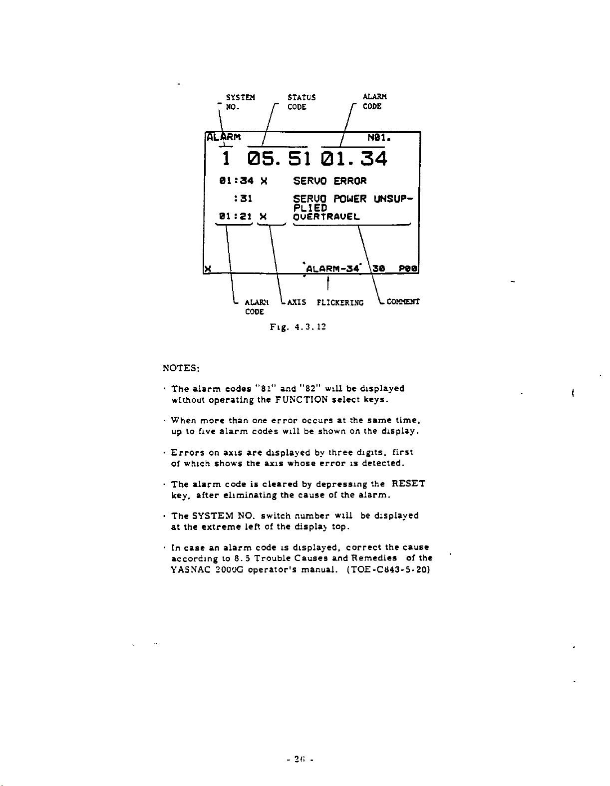
SYSTEM
NO.
7
STATUS
CODE
ALARM
CODE
NOTES:
•
The
alarm
without
•
When
to
up
AUSRPI
1
01:34
:
01:21
codes
operating
more
five
than
alarm
05.
31
ALARM
CODE
one
codes
X
X
Fig.
”81"
the
FUNCTION
error
51
01.
SERUO
SERUO
ERROR
POUER
PLIED
OUERTRAUEL
"ALARM-SA*
AXIS
FLICKERING
4.3.12
”82"
occurs
shown
be
will
select
and
will
at
34
displayed
be
the
on
N01.
UNSUP¬
\3a
COMMENT
keys.
same
display.
the
peal
(
time,
•
Errors
which
of
•
The
key,
•
The
the
at
case
In
-
according
YASNAC
on
shows
alarm
after
SYSTEM
extreme
an
200UG
are
axis
the
is
code
eliminating
NO.
left
alarm
to
8.5
operator's
code
Trouble
displayed
axis
cleared
the
switch
the
of
is
whose
by
cause
number
display
displayed,
Causes
manual.
by
three
error
depressing
the
of
will
top.
correct
and
(TOE-C843-5-
digits,
is
detected.
the
alarm.
be
displayed
Remedies
first
RESET
the
cause
of
the
20)
«
2
-
-
Page 31

4.3.10
OPERATION
Operation
of
time
may
a
system.
I.
automatic
be
used
workpiece
Depress
lights
in
Key
2.
operation
The
CRT
hours,
represents
automatic
is
lamp
power.
To
3.
reset
CAN
and
OPERATION
(
HOUR
time
the
up.
likely
minutes
on.
display
know
to
total
or
PRM
as
not
is
display
an
operation
It
display,
the
keys
TIME
TIME
DISPLAY
shows
operation
the
operation
"N,”
of
working
key,
"0,’’"0."
needed.
shows
and
operation
seconds.
accumulated
while
not
is
cleared
depress
simultaneously.
MIN
SEC
the
machine.
time
and
time
CYCLE
time
then
The
This
by
the
N01.
totalized
It
to
finish
of
the
the
lamp
WR
time
display
of
the
START
turning
PRM
displayed.
key
at
keyed,
key
the
a
new
as
there
the
set¬
can
01
through
by
Refer
01
the
the
may
in
2.
3.
Key
through
The
Key
any
09
data
in”!"
(acceptable
The
keyed*
left
bottom
depress
first
number
right
key
Depress
4.
in
off
The
parameter
parameter.
NOTES:
•
This
during
Depending
happen
ting
function.
also
as
09
setting
the
to
keyed-
operation
the
have
to
changed
be
well
the
machine
the
automatic
upon
of
one
following
already
”0"
or
any
in
data
corner.
the
in
WR
m
data
storage
can
a
a
case
In
on
as
on
SYSTEM
tool
parameter
stored
following
except
will
CAN
again.
key.
will
and
be
operation.
type
such
the
all
other
NO.
builder's
the
If
made
of
of
a
case,
parameters
numbers
key.
N
will
m
the
).
N
displayed
be
a
number
and
key
stored
be
displayed
at
any
machine,
preventing
the
parameters,
switch
manual.
be
X
mis-
then
into
time..even
data
to
"1."
01
<
r
4.3.11
Parameter
function
SYSTEM
criminatingly
those
ings,
The
1.
SETTING
and
all
of
see
operating
Depress
lights
10.
numbers
can
NO.
other
Table
the
up.
02.
Fig.
FUNCTION
be
written
switch.
called
be
parameters.
4.3.9
procedure
PRM
01
4.3.10
to
This
the
List
key,
53
09
is
assume
without
function
setting
of
as
and
00
switching
operation
can
function
For
their
Parameters.
follows.
then
the
dis¬
from
mean¬
lamp
4.3.12
The
machining.
INPUT
and
alarm
on
and
1.
control
it
the
the
If
ALARM
ERROR
stops
code
CRT
lamp
the
control
is
When
operation.
and
display
lights
expressed
at
the
bottom
the
2.
ing
Depress
of
The
alarm
List
the
FUNCTION
the
status
message
Alarm
of
detailed
STATUS
AND
always
or
in
diagnosing
the
control
ALARM
NC
alarm
message
when
up.
detects
"ALARM-CC,"
the
of
CRT
select
ALM
key.
and
alarm
will
Codes
meanings.
CODE
detects
The
corresponding
the
ALM
an
error,
display,
key.
codes
be
displayed.
and
Status
DISPLAY
even
lamp
will
as
an
lights
be
key
a
message,
will
well
Codes
during
error,
up
displayed
pushed
is
flicker
disregard¬
as
the
the
See
for
25
-
-
Page 32

SYSTEM
NO.
r
STATUS
CODE
r
ALARM
CODE
NOTES:
•
The
without
When
to
up
alarm
more
five
1
01:34
:
01:21
codes
operating
than
alarm
05.
31
ALARM
CODE
one
codes
--/
X
X
Fig.
"31"
and
FUNCTION
the
error
will
7~
51
AXIS
01.
SERUO
SERUO
PLIED
OUERTRAUEL
‘ALARM-34*
ERROR
POWER
t
FLICKERING
12
4.3.
"82"
will
select
occurs
be
at
shown
34
be
displayed
the
on
N01.
UNSUP¬
\38
COMMENT
keys.
same
the
display.
time,
f
%
Errors
•
which
of
•
The
key,
•
The
the
at
In
-
case
according
YASNAC
on
axis
shows
alarm
eliminating
after
SYSTEM
extreme
alarm
an
to
200QG
code
8.
are
the
is
NO.
left
code
Trouble
5
operator’s
displayed
axis
cleared
the
switch
the
of
is
by
whose
by
cause
number
display
displayed,
Causes
manual.
three
error
is
depressing
the
of
will
top.
correct
and
(TOE-C343-5-
digits,
detected.
the
alarm.
be
displayed
Remedies
first
RESET
the
cause
the
of
20)
E!
2
-
-
Page 33

List
of
Alarm
Messages
:
20:
:
02:14
is:
:
:
:
02:21
:22
01
:
08
:
01
:
:
03:
;2S
:3i
01:32
‘.33
01:34
:35
02:36
137
:ss
2A6:
1
15:82
i
12
13
15
16
17
18
23
24
25
26
27
1
TEMPERATURE
ALARM
IN
TAPE/MEMORY
ZONTAL
TAPE
TY
FORMAT
DATA
TOOL
ERROR
PARITY
UERTICAL
ERROR
ERROR
ERROR
OFFSET
PARAMETER
THE
AREA
RISE
PANEL
HORI¬
ERROR
PARI¬
AREA
ERROR
X
x
X2
TAPE
OUERTRAUEL
Z
REFERENCE
TURN
REFERENCE
Z
TURN
REFERENCE
TURN
SEQUENCE
SPINDLE
POSITIONING
MOCHIHE
SERUO
MEMORY
AREA
UNREADY
POSITION
POWER
ERROR
ZERO
ERROR
ZERO
2ER0
ERROR
ERROR
ERROR
ERROR
UNREADY
UNSUP¬
RE¬
RE¬
RE¬
PLIED
UNIT
STOP
ERROR
ERROR
ERROR
ERROR
CPU
ERROR
COLLATING
£F6)
CRPS)
81
CONTROL
UNREADY
EMERGENCY
X
Z
SERUO
OUERLOAD
FEEDBACK
HARDWARE
HARDWARE
SYSTEM
MEMORY
ERROR
27
-
-
Page 34

Tahly
3.
12.
I
List
of
Alarm
Code
and
Status
Codes
4.
\.
Ansi
Pile
C
LI
12
13
H~ll4
1
j
15
16
17
18
21
D
22
H
23
24
25
26
I
Excessive
Zero
the
panel.
error.
vertical
error.
error.
memory
return
return
return
m
Tape/Memory
J
.
paritv
;
Tape
Format
:
Data
Offset
Parameter
Tape
Overtravel.
Zero
Zero
|
Sequence
j
Spindle
Causes
temperature
error.
error.
error.
error.
horizontal
parity
error.
area
unready.
position
error.
error.
error.
rise
|
,
!
i
i
[
1
Alarm
Code
D27
D32
23
31
33
34
35
36
37
33
31
82
91
92
Positioning
Machine
Servo
Control
Emergency
Servo
Overload.
Feedback
Hardware
Hardware
1
CPU
Memory
1
Contents
between
(For
Tape
(For
Causes
unready.
power
unit
error.
error.
error
error
error.
collating
disagreement
tape
off-line
reading
off-line
error.
unsupplied.
unready.
stop.
(FG).
(RPG).
error.
and
memory.
)
only.
error.
)
only
_
(
Status
Code
!_
Notes:
1.
2.
For
3.
IC
4.
52
53
54
55
56
~
error
I
"H
or
rTl
|
1
;
Performing
Distributing
.
Performing
and
Reading
Performing
and
•
,
Distributing
j
Performing
I
and
alarm
of
is
of
status
function
T
alarm
number.
of
alarm
distributing
reading
distributing
code
detected.
code
which
code
code
tape.
"12,"
M-,
pulses.
M-,
M-,
tape,
pulses
M-.
is
filled
1
is
filled
is
"
14.
Status
S-,
and/or
Dwelling.
S-,
and/or
pulses.
S-,
and/or
and
S-,
and/or
pulses
with
X-axis.
with
executed.
being
additional
II
H
15"
_
reading
and
a
digit
2:
a
digit
two
shows
T
function.
-
T-function,
T-function,
tape.
T-function,
reading
indicating
Z-axis.
indicating
1-
digits
the
tape.
M,
indicate
detailed
Remarks
52
51
I
the
either
2:
error
S,
51
51
52
+
axis
4:
the
*
+
54
+
54
S2
54
+
whose
S,
M,
T.
memory
causes.
28
-
-
Page 35

Table
4.3.
12.2
Display
Examples
of
Alarm
Codes
Combined
with
Status
Codes
Alarm
1.55
.
54
.52
1C
.
and
Status
.12
20.
01.21
36.
Code
12
81
i
horizontal
A
"12”
cuting
the
tape
"51"
horizontal
A
"12")
(status
The
An
overtravel
X-axis
occurs
The
a
to
code-
1C36.
occurs
the
M-function
reading
"54")
+
occurs
code:
defective
(additional
during
operation
mal-
operation
"81").
Meaning
parity
while
the
in
parity
while
"54")
IC
(alarm
the
cannot
The
(status
number
(code:
in
code:
be
the
(alarm
code:
mode.
(alarm
MEM
the
is
code:
continued
CPU
address
a
20.
error
simultaneously
TAPE
error
reading
alarm
automatic
of
active
code:
exe¬
"1")
and
"55"
code:
memory
mode.
"21")
of
"l")
operation,
due
(alarm
is
«
Note;
During
will
flicker
09.
execution
at
the
82
of
bottom
M-,
S-
of
A
resulted
the
ber
and/or
CRT
the
total
error
memory.
is
"09.
T-function,
display.
TSM-FIN
FLICKERING
from
"
(alarm
the
The
self-
defective
the
10
code.
diagnostics
following
"82")
BOM
message
is
of
num¬
-29-
Page 36

4.3.13
DISPLAY
OF
INPUT/OUTPUT
SIGNALS
Wide-Display
-
the
All
the
automatic
The
1.
2.
input/output
operator's
operating
Depress
INPUT
The
designated
played.
in
Key
displayed.
In
case
a
in
2
In
case
a
in
2-
The
ON/OFF
designated
displayed
DIAGNGSIS
XU
operation.
procedure
the
a
diagnostic
an
of
-digit
of.an
digit
by
signals
at
panel
DGN
any
key.
/OUTPUT
diagnostic
number
input
diagnostic
number
output
number
status
by
"l"
the
or
following
diagnostic
following
diagnostic
"0."
is
signal
number
of
can
time
as
a
be
follows.
desired
group
-7-6-5-4-3-E-l
11100000
checked
even
status
will
number:
X.
number:
Z.
of
number
N01.
-0
during
the
of
be
dis¬
to
signals
will
be
Key
on
Key
be
S.
*
“
u
-J
6.
Depress
display
The
mode,
rently
displayed.
in
designated
DIAGNOSIS
XI
XXI
U
XI
X14
XI
XI
XI?
Depress
The
page
the
which
0
1
3
5
6
the
turns
will
PAGE
DCN
key
replace
a
page
diagnostic
S
6
?
00090000
1
1
1
11111111
0
0
0
0
0
0
0
0
1
0000000*
0000001
0:OP£N
CLOSED
:
1
Fig.
4.3.
key.
1
the
to
page
again.
wide-display
the
containing
number
4
2
3
0
0
0
0
0
0
0
1
0
10
10
13.2
plus
1
0
0
1
one.
the
0
0
1
0
9
1
cur¬
will
NDI.
1
be
1
Note:
designates
shows
designated.
3.
Depress
The
nostic
Depress
4.
liThe
nostic
Keying
the
group
number
group
number
0:
OPEN
:
CLOSED
I
the
status
LINE]
!
the
L_i
of
signals
I
LINE
the
of
signals
7.
Depress
The
page
one.
8,
1
1
1
4.3.
after
the
group
key.
designated
one
will
j
key.
designated
one
13.
"X,"
number
be
will
and
"1."
"01"
signals
of
the
by
displayed.
the
by
displayed.
be
"0"
and
diag¬
diag¬
Fig.
"1"
in
diagnostic
of
__
I
plus
minus
Depress
Cancelling
play
mode.
NOTE:
moved
wide
display.
4.3.14
A
specific
searched
but
also
S
and
Z,
tion.
program
part
program
part
Further,
searched
in
ister
returns
The
by
ADDRESS
by
T,
A
part
the
the
returns
the
the
line
operating
block
not
only
all
address
according
program
in
in
attention
block
EDT
PAGE
back
DGN
wide-display
backto
designation
the
SEARCH
the
on
the
be
TAPE
the
the
MEM
should
won't
enter
mode.
key.
to
key.
the
normal-
LINE
part
sequence
character
the
to
be
to
mode,
or
be
into
the
page
mode,
("o"
mark)
key
program
number
such
following
searched
while
EDT
taken,
the
minus
display
during
c
is
mode.
because
buffer
the
dis¬
can
the
an
be
"N,
as
C,
opera¬
a
taped
a
stored
reg¬
be
"
X,
the
30
-
-
Page 37

1.
2.
3.
4.
5.
6.
NOTES-
A
enters
instructed
r
•
In
But
MEM
Leading
-
dress
search
NO
All
*
modal
data
Operation
•
•
Reset
•
the
Set
MEM
Depress
lights
Depress
Then,
the
stored
Key
in
desired
EXAMPLE
keyed
mis-keyed,
ber
then
and
EXAMPLE
detected
less
of
Depress
When
dress
the
BUFFER
tion
stops.
To
suspend
the
RESET
block
values
EDT
the
the
enter
modified
BUFFER
mode.
characters
12
.
commands
one
enters
the
CYCLE
search
the
dress
so
any
But,
TAPE
reset
searchinthe
causes
operating
after
modes.
operation.
MODE
or
EDT.
the
-ÿ
up.
the
the
LABEL
an
address
to
"MOi”
in,
key
"M"
the
the
the
address
data
searched
buffer
the
in
modified
are
mode,
edit
with
zeros
operation.
are
in
begins
START
is
operated
control
format
address
SELECT
COM
P09
RESET
part
be
searched.
In
1:
in
2:
"M.""-":
code
number
AS
concurs
lamp
the
key.
register.
same
the
buffer
tool
lamp
may
in
not
the
mode.
Cycle
key,
key.
SKIP
program
data
case
that
is
to
be
first
depress
the
correct
istobe
of
M.
(address
search
with
lights
search
in
the
operation,
TAPE
block,
with
searched
the
register
on
is
suppressed
be
For
searched
value
likewise
example,
offset
including
the
recognized,
buffer
with
before
key
in
register.
the
is
the
Cycle
EDT
(alarm
error
search
Start
switch
and
lamp
is
rewound.
(or
only
"M."
searched:
number
When
searched,
search)
starts
the
instructed
and
up
or
a
If
coordinate
offset
tool
without
N
in
blocks
searched
depressed
TAPE
mode.
the
in
can
to
then
lights
an
"0,"
the
the
and
the
MEM
tool
block
and
in
address
N
and
or
Start
Failure
code:
MEM
made
be
TAPE,
the
up
address)
If
CAN
again.
initially
key.
opera¬
depress
offset
values.
will
being
so
on.
tape
all
for
12
including
only
block,
after
MEM
after
lamp
and
"l"
a
num¬
key
regard¬
the
ad¬
data,
mode
and
ad¬
means
update
mode.
to
"14")
and
without
are
is
if
a
ad¬
do
4.3.15
TV
check
in
lected
setting,
With
With
With
including
ERROR
ation
parity
ber
space
4.3.16
The
current
current
is
panel
incorporated
position
1.
2.
check
in
TAPE
with
No.
No.
TV
in
error)
characters
of
code
movement
installed
as
Depress
axis
The
TV
see
lamp
the
CURRENT
position
position
display
to
display
CHECK
used
is
block
each
mode.
parameter
4.3.9
1"
"8
"81"
Check
EOB
lights
TAPE
is
as
separately
external
into
the
reset
(VERTICAL
make
to
during
check
TV
Writing
"0"
at
at"l"
if
ON,
in
code
up
mode.
displayed.
a
in
additional
POSITION
the
of
each
of
display
current
the
unit.
display
current
the
cannot
PARITY
the
vertical
reading
tape
ONorOFF
No,
81.
For
Parameters.
•
•
the
the
during
block
TV
•
•
TV
number
block
tape
Alarm
To
to
Check
Check
is
adjust
be
chatacter.
DISPLAY
toolissummed
is
The
the
position
as
internal
pushbutton
position
affected
displayed
NC
axis
unit.
from
panel
reset
be
parameter
characters
of
odd,
reading
code
even,
UNIT+
up
display
operator's
display
of
the
by
CHECK)
parity
operation
canbese¬
OFF
ON
INPUT
oper¬
(TV
"13”
the
num¬
a
use
and
the
on
the
unit
unit
current
at
each
the
axis.
G50
or
command.
even
be
LOCK
*
power
the
J
L
L
updated
switch
changed
be
switch
machine
U
D
J
l.JQ
J
Fig.
on.
supply
C
J
i.
4.3.16
LOCK
the
follows
-
can
cannot
servo
I
i
iJDuccn
i
display
The
3.
MACHINE
the
display
The
4.
DISPLAY
Even
5.
if
display
X
Z
in
in
on.
case
in
is
movement.
Cl
i
a
i
case
off,
of
the
of
the
RESET
o
RESET
O
-31-
Page 38

4.4
Tool
the
the
Tape
LABEL
T1
.T2
T3
ER
The
offset
lows.
STORING
NCTAPlt
offset
DATA
of
form
format
*
•••Z•••
X
•
•
X
*
X
%)
(or
operating
values
TOOL
values
keyboard.
punched
tool
for
2
•••
Z
•
_•
procedure
from
OFFSET
are
They
tape.
offset
•••
R
•
•
R
•••
R
Rewind
the
punched
usually
*
-
*
stop
for
VALUES
written
can
be
values
code
storing
tape
FROM
input
is:
the
is
through
also
tool
as
fol¬
to
The
offset
OFS
the
read,
EDT.
LABEL
the
values
the
the
key
tool
memory.
the
the
will
CRT
lamp
Label
operation
held
offset
opera¬
storing
be
kept
display.
on
in.
1.
Set
2.
Depress
SKIP
in
3.
4.
5.
Depress
lights
Set
the
Skip
as
Depress
The
values
Once
tion
operation,
flickering
MODE
the
lamp
up.
punched
tape
function
stated
tape
enter
a
rewind
stops
SELECT
RESET
the
lights
OFS
the
tape
reader.
is
effective
in
step
TAPE!
the
IN
reading
into
stop
automatically.
"TAPE
at
bottom
the
up.
key.
the
of
At
2.
I
starts
the
code
IN"
switch
key.
Then,
tool
this
using
with
key
and
tool
is
message
of
time,
offset
During
the
PART
4.5
4.5.1
The
STORING
NC
Maximum
Table
4.5.1.
PROGRAM
data
tape
capacity
•_
PART
are
of
B
s
0
0
a
STORAGE
PROGRAM
stored
the
memory
©
tziaasa®
BEEBES)
Ezazza
©
t
FROM
NC
TAPE
memory.
the
into
shown
is
O
@
B30
@®@
0®®
®0®
©®o
a
Z
0
0
z
S
0
Z
a
(•
o
4.4
Fig.
4.5.
1
Tape
Approx.
Approx.
Approx.
Approx.
Approx.
Length
10
20
30
40
80
m
m
m
m
m
Table
Specifi¬
cationÿ
A
B
in
C
D
E
Memory
Capacity
4000
characters
8000
chatacters
12000
characters
16000
characters
32000
characters
32
-
-
Page 39

Part
program
rewind
with
or
M02
final
the
CEL
Tape
code
Where
tive
will
EIA
Follow
tape
1.
automatic
with
automatically
ISO
or
the
data.
MODE
Set
stop
M30
block
is
parameter
character
procedure
punched
code
command
the
of
REWIND
EIA:
ISO:
Fig.
specified
selection
adjust
SELECT
(EIA:
must
program.
STOP
"ERM
"I”
5.
4.
No.
format.
below
should
Mu*
1
1.
by
parameter
80
to
switch
be
”ER,"
be
programmed
p
*
CODE
of
tape
"l,"
*
read
to
store
to
sandwiched
ISO:
<
No.
code
is
control
the
with
tape
the
punched
EDIT.
"l").
82.
effec¬
either
2
Depress
memory
3.
4.
5.
The
SKIP
the
part
dress
Depress
lights
allowed
is
key
in
Set
the
unit.
is
effective.
Depress
The
tape
grams
Once
ration
lamp
of
up.
principle.
Be
the
stops
in
the
lights
program
the
the
Any
to
punched
sure
the
reading
the
in
rewind
RESET
is
memory.
COM
be
that
TAPE
i
IN
i
tape
automatically.
key.
rewound
being
up,
orderly
key.
FUNCTION
However,
set.
onto
tape
Label
the
key.
enter
and
into
code
starts
stop
and
the
ready
from
Then,
key
the
tape
Skip
the
the'memory.
read,
is
LABEL
to
the
the
except
use
reader
function
part
store
first
lamp
pro¬
the
ad¬
OFS
COM
ope¬
4.5.2
To
the
procedure.
will
gram.
1.
2.
PART
TAPE
modify
middle
be
Set
Depress
lights
the
of
erased
MODE
the
up.
PROGRAM
program
part
a
block
The
part
by
off
SELECT
the
COM
0
[21
S
0
3
3
MODIFICATION
data,
of
programs
storing
key.
0IH
000BH11I]
00S0SE
0E0
already
use
already
new
the
switch
Then,
0
the
to
the
<0
A30Sf
FROM
stored
following
part
EDT.
0110
000
Fig.
NC
in
stored
pro¬
lamp
'
to
.
'
000
.
>*'*
®®@
®(D©
®@®
0®O
1.2
4.5.
3.
Search
will
Set
4.
Be
Depress
5.
The
—
>
be
a
punched
sure
effective.
new
memory,
address
0
_
0
0
0
the
stored.
that,
the
tape
beginning
is
US
03
(D
_
0
block
in
tape
the
TAPE
data
searched.
0
e
which
onto
Label
key.
will
from
the
Skip
be
the
tape
stored
the
new
program
reader.
function
into
block
is
the
whose
33
-
-
Page 40

STORED
PROCRAM
NEW
PROGRAM
TO
INSERTED
BE
NC
BLOCK
~3
—
Fg3
SEARCHED
r
\
1
CH
Fig.
4.5.2
NOTES:
•
the
If
a
parity
restore
•
During
[TAPE:
I
IN.
flickering
4.5.3
When
through
the
1.
2.
3.
STORING
storing
following
Set
Depress
The
SKIP
the
the
of
Depressÿ
lights
storing
error,
the'new
the
tape
key.
;
i
at
keyboard
the
MODE
the
the
memory
lamp
program
memory.
the
up.
operation
or
data.
storing
"-TAPE
the
bottom
PART
the
part
procedure.
SELECT
RESET
is
rewound
lights
orderly
COM
is
interrupted
depressing
operation
IN"
message
the
of
PROGRAM
program
on
the
operating
’
switch
key.
and
up,
being
from
key.
CRT
FROM
into
ready
the
Then,
the
the
RESET
via
will
the
to
EDT.
LABEL
first
the
due
the
be
display.
MDI
memory
panel,
to
store
address
lamp
to
key.
kept
use
Depressing
makes
program
display
vertically
4.
Key
EXAMPLE:
The
bottom
number
first
Depress
5.
The
fer
lights
Repeat
6.
values
Check
7.
depress
A
into
turns
register
terisk
in
keyed-
and
keyed-in
register,
block
the
off.
the
display
mode,
an
left
is
key
the
up.
steps
a
of
the
the
of
memory,
will
mark
COM
the
display
the
double
address
||
data
in
corner
mis
-keyed,
in
the
WR
data
and
and
4
block
command
STR
data
will
data
All
be
('••)
displayed.
turn
mode
displayed
the
data
(o)
jjj
will
of
correct
key.
stored
is
then
5
into
values
key,
be
and
stored
deleted,
in
key
the
to
a
of
regular
desired.
'jj
displayed
be
the
display.
depress
BUFFER
the
write
to
edit
the
collectively
the
then
in
leaving
the
EDT
edittmg
block.
characters
size.
the
number.
into
the
command
the
buffer
stored,
BUFFER
the
edit
only
In
at
the
If
CAN
edit
lamp
register.
and
stored
mode
part
this
the
then.
lamp
buffer
an
key
buf¬
(
as¬
COMMAND
mi
CN001
IT
-ED
G50
650
xm
00.
XI
2200.*
Ml)
Fig.
-
N01
gi
4.
34
5.3.
-
.
MEMORY
•
DISPLAY
5TR
KEY
I
I
EDIT
BUFFER
DISPLAY
pee
1
Page 41

8.
9.
10.
11.
Repeat
blocks
sure
Be
the
at
After
the
input
See
4.
gram.
Correct
See
4.6.2
Depress
program
part
4
steps
are
stored
to
instruct
final
block
depressing
data
by
6.
1
Display
the
data,
Editing
the
through
into
of
the
displaying.
if
RESET
after
7
until
the
memory.
M02
or
the
program.
RESET
of
Stored
a
mistake
Stored
completion
Part
key
M30
Part
to
all
necessary
command
key,
Pro¬
is
found.
Program.
rewind
of
the
check
the
operation.
lights
In
case
Depress
By
doing
wide-display
the
to
program.
characters
covers
play
reason,
referring
been
have
Follow
the
step
all
of
the
so
the
to
stored
3.
up.
the
COM
in
In
are
over
new
a
the
Then,
wide-display
key
the
EDT
mode
this
display
the
of
about
blocks
several
by
steps
the
LABEL
twice
mode,
of
mode,
regular
nine
can
number
the
previous
mentioned
in
the
size,
lines.
be
step
the
display
editing
the
stored,
of
blocks
operation.
above
SKIP
3.
part
displayed
and
the
For
this
always
except
lamp
turns
dis¬
which
for
4.5.4
Parameter
of
part
cuted.
of
characters
which
shown
ADDRESS
No.
program
the
With
the
pointer
on
the
FLICKERING
DISPLAY
is
99
in
memory
parameter
from
in
display.
first
the
used
COMMAND-EDIT
N001
..N002
AN003
'
(N0O3
OF
TAPE
to
display
which
is
99,
No.
address
control
to
indicates
GSO
600
X0
2500*
Z£00S)
X0
MEMORY
address
the
exe¬
being
number
the
the
address
is
XI
S
Fig.
1
00.
000
4.
N0S.
2200.*
T0101
3.
5.
M03*
2
PlEmORV-POlNTER
0
21
2485
MEMORY
DISPLAY
.
-
EDIT
BUFFER
}
DISPLAY
STR
1
—
N01.
EXAMPLE:
•
Set
the
data
tape
number
the
on
the
•
If
parameter
operation
of
play
be
updated.
characters
the
block
into
the
parameter
in
the
of
characters
display.
in
active
from
preceding
buffer
EDT
the
address
The
register.
No.
No.
MEM
display
the
at
mode,
in
99
mode,
on
head
the
99
after
and
the
tape
designated
is
the
showB
of
part
latest
the
tape
storing
the
is
position
memory
the
program
block
total
displayed
during
number
stored
the
dis¬
can
to
99
The
pointer
of
points
Fig.
35
-
-
out
the
4.5.4
2485
character.
th
Page 42

4.6
6.
4.
This
stored
display
ating
Set
1.
Depress
2.
The
er
also
Depress
3.
The
pointer
memory.
lights
Depress
4.
The
will
value.
data
edit
Repeat
5.
of
The-display
6.
block
A
7.
by
4.3.14).
After
8.
checking
key
t
EDIT
DISPLAY
1
an
is
the
in
order
in
procedure
the
data
will
displayed
stored
up.
first
be
are
buffer
each
by
block
use
the
completion
to
rewind
0P
operation
memory
to
is
MODE
be
points
SELECT
the
COM
a
block
of
displayed.
RESET
the
part
Then,
the
block
displayed.
See
the
displayed
display.
step
block.
to
4
can
depressing
be
can
of
address
operation,
the
STORED
to
display
on
check
as
follows.
key.
pointed
in
edit
program
the
out
the
LABEL
of
the
Check
4.
Fig.
in
.
check
be
returned
the
designated
this
of
depress
memory.
PART
CRT
the
the
data.
switch
(The
buffer
key.
is
head
stored
the
1.1.
6.
memory
all
command
iTTOE'
*
and
search
displaying
PROGRAM
a
part
character
to
out
by
block
display.
rewound
address
SKIP
part
command
The
display
the
to
key.
be
function
the
program
The
oper¬
EDT.
the
point¬
data
)
and
of
lamp
program
same
values
previous
confirmed
(see
and
RESET
is
the
and
the
Check
Described
blocks
several
correlation
firmed.
Set
1.
Depress
2.
By
display
the
In
are
out
ed
3.
Depress
The
pointer
memory.
lights
4.
Depress
several
A
about
the
of
(see
Check
5.
Repeat
6.
By
depressing
display
play
a
specified
function.
Similarly,
7.
operation,
wind
the
on
above
one.
by
number
between
MODE
the
the
doing
mode
mode
displayed
the
by
the
stored
points
up.
the
nine
first
the
figure
all
command
steD
can
be
can
stored
the
wide-display
is
the
blocks
of
SELECT
COM
the
so,
the
of
block
the
collectively
pointer
RESET
program
part
out
Then,
PAGE
+
number
are
lines
block
below).
check
to
4
the
be
checked
jumped
block
after
completion
depress
part
procedure
Collectively
in
two
blocks
key
display
editing
dataofabout
at
key.
head
the
the
LABEL
key.
of
block
displayed
the
of
values.
each
|p-yÿ|
back
using
the
program.
-
a
group,
switch
twice.
turns
with
the
head.
is
address
data
stored
key,
again
a
to
the
address
RESET
of
displaying
can
to
program.
part
a
rewound
SKIP
consisting
taking
part
display.
the
and/or
page
of
the
checking
block
the
con¬
be
EDT.
wide-
to
nine
block
and
the
of
lamp
the
program
previous
the
containing
search
checking
to
key
the
a
lines
point¬
the
of
lead
1
dis¬
re¬
COMMAND
N001
-ED
IT
G50
N001G50
XI
40.
X140.
Fig.
NOB.
230.1
230.1
10
4.6.
1.
1
36
-
-
MEMORY
—
(1
EDIT
DISPLAY
-
DISPLAY
BLOCK)
BUFFER
Page 43

COMMAND-EDIT
N0Z.
NOTES:
The
•
the
EDT
m
the
command
been
modified
modal
to
be
.
During
EDT
newed
while
unchanged
display.
block
mode
EDT
input
by
command
displayed
the
mode,
by
the
FLICKERING
displayed
greatly
mode.
is
displayed
in
the
EDT
a
tool
instructed
is
included.
display
the
displayed
the
LINE
number
at
the
of
exstreme
using
differs
Namely,
values
mode,
offset
with
or
"page"
the
value
the
picture
PAGE
right
>:NB01
/
N002
N003
N004
NOBS
NOBS
N00?
NO
NO09
N001
COM
from
coordinate
the
as
without
of
except
COM
key
"line"
or
bottom
08
that
that
others.
in
key
can
operation
Nun
650
GOO
G41*
X0
ZS00S
SOI
X2B00*
2-2000*
X3080
U-2000
612
650
Fig.
in
key
except
have
being
No
block
the
in
the
re¬
be
remains
the
of
5
XI
S]
ZO
U-1500
XI
40.
,
NOOS
40.
208
FZ0*
4.6.
Z30.
T02O2
S900*
300*
X
Z30.
1.2
4.6.2
Stored
in
the
Editing
N
00$
*
M03*
*
EDITING
part
EDT
—
-
*-
10
program
mode
ERS
(insert)
INS
ALT
N'U09
PCD
STORED
using
(erase)
(alter)
can
DISPLAY
PART
be
the
MEMORY
WIDE
EDIT
DISPLAY
(THIS
ASSIGNED)
BE
PROGRAMt
edited
following
To
To
To
erasing,
ing,
address
a
BUFFER
BLOCK
and
keys.
delete
insert
modify
and
block.
TO
modified
block
block
block:
insert¬
modifying
in
data
The
using
can
be
or
in
•
Deleting
key)
1.
editing
the
COM
made
the
wide-display
part
A
blocktobe
pressing
SEARCH)
operation
key
both
in
program
|
LjNE|
key.
below
the
in
the
mode.
deleted
L\NE|
|
,
is
EDT
normal-
block
designated
is
carried
mode.
display
(ERASE:
or
AS
ERASE
Fig.
out
Editing
mode
ERS
de-
by
(ADDRESS
4.6.2.
37
-
INSERT
Nnnr
1
2.
-
N010
V
Check
described
Program.
FER
Depress
ed
The
automatically
BUFFER
lamp
block
next
the
the
from
ALTER
data
in
lights
block
lamp
referring
4.6.1
this
With
up.
ERS
the
is
read
displayed
remains
3
Display
operation,
to
key
memory.
out
on
to
the
delete
and
the
on.
procedure
of
Stored
the
its
display.
the
search¬
data
Part
BUF¬
is
Page 44

FLICKERING
(
-I
KEY:
0
FLICKER¬
ING
block
GS0
Gee
S41*
X0
G01
X2000*
2-2000*
X300
812
G01
v.,
rXNeeS
iN
N005
N001
N002
N003
N004
N006
N00?
N008
N009
N00S
COMMOND-EDIT
03
06
09
06
£50
G00
641
X0
X2000*
2-2000*
X3000
G
Sll
X2000*
N001
N002
N0
N004
>.'N0
N007
N008
N0
N010
NC
la
12
X
40.
1
200
SI
Z500*
Z0
0
UJ-1S00
U-2000
20
deleted
X
40.
1
S
1
200
*
Z500*
U1-1S00
LJ-2000
X5000
F2C*
F20*
and
230.*
T0202
S900*
1300*
N006
230.*
T0202
2900*
1300*
K
-380
N02.
M03*
designated
Is
N02.
M03*
S500*
10
P00
via
To
designate
block
a
be
Co
Che
ERS
This
designated
deletion.
desired
deleted.
key.
block
Co
after
be
Fig.
4.
6.2.2
10
P00
38
-
-
Page 45

To
3.
blocks,
the
4.
If
the
cedure
•
Inserting
A
1.
using
SEARCH)
block
ed
To
depress
delete
ERS
the
deleted
block
block.
insert
the
key
block
of
"Inserting
BLOCK
a
block
desired
lLINEl
+
key.
will
the
a
serval
block
is
is
accidentally
data
Nons
Fig.
be
inserted
the
first
RESET
consecutive
can
be
depressed.
again
according
a
N006
DELETED
6.
4.
(INSERT:
inserted
be
to
|LI/JE|
Check
block
key.
N006
deleted
block"
3
2.
or
the
right
of
NOOB
erased,
given
INS
(ADDRESS
AS
data.
after
the
number
every
insert
the
to
below.
3
key)
is
designated
A
new
the
select¬
program.
of
time
pro¬
BUFFER
asterisk
of
the
the
Command
the
in
stored
even
the
the
will
display
data
2.
3.
Depress
The
an
message
tom
Insert
Writing
from
keyed-
been
Once
using
by
up.
COMMAND-EDIT
NBfll
N002
N003
N
X
00
N
N0B6
-
£
in
N004
N00?
N003
N009
N010
NO
_
-
f
i
I
ivs
Insert
block
(To
be
written
after
is
designated.)
INS
mark(*)
CRT
data
without
one
WR
4
05
key.
limp
be
kept
display.
of
in
will
the
of
key,
650
GOO
64}
X0
X2BO0*
Z-2000*
X3000
612
611
S01
turns
displayed.
flickering
a
block
Data
the
displayed
be
any
address
the
X140.
SI
a
Z50O*
U-2000
XS000
20
off,
leaving
according
MDI.
by
mode,
MDI
as
modification.
data
BUFFER
230.
T0ZB2
200
Li-1500
J30C
K-300
F20*
“INSERT*
'
t
FLICKERING
only
"INSERT"
at
the
bot¬
to
4.3.2
Differing
the
it
has
is
written
lamplights
N02.
*
M03*
S900*
*
SS00*
10
;
i
POO
FIRST
OF
ADDRESS
THE
MEMORY
BLOCK
ING
BLOCK
INSERTED
PRECED¬
THE
NEW
TO
Fig.
BE
-/
4.
6.2.
X
BLOCK
INSERTED
4
l
Fig.
4.
6.2.
5
-39-
Page 46

Depress
4.
Block
ing
off.
sertedblock
turns
Repeat
5.
blocks
Modifying
•
key)
1.
Designate
.’LINE
key
lamp
displayed
Key
2.
fied,
data
corner
display
*
and
in
will
the
insertion
The
display
off.
steps
sequence.
in
part
LINE)
•
!
check
lights
an
example,"
for
be
of
INS
of
the
and
2
program
the
block
j
+
the
and
up.
at
the
address
displayed
the
display.
key
is
executed
message
shows
then
through
to
..
or
AS
data.
the
edit
data
F,
again.
the
the
BUFFER
to
4
block
be
altered
,
(address
Then,
designated
buffer
desired
"'3;'
'S'.’
at
the
•
the
and
"INSERT"
data
insert
(ALTER:
register.
left
the
The
the
of
lamp
new
using
search)
BUFFER
block
be
to
keyed-
bottom
flicker¬
turns
in-
ALT
the
is
modi¬
in
4.
Input
2
built.
Depress
5.
New
old
Check
6.
ed
block.
To
the
mode
NOTES:
•
To
block
"/"
delete
To
out
-"/"and
new
and
block
block
block
facilitate
normal-
write
skip
and
the
of
command
3
until
Check
the
is
is
the
new
and
display
depressing
by
the
character"/"
the
in
"l"
first
"/"
edit
depress
then
desired
new
the
ALT
stored
deleted.
data
its
checking
edit
and
character
buffer
data
by
repeating
data
of
data.
key.
memory
into
displaying
by
preceding
the
shift
modetothe
COM
the
for
buffer
then
register,
the
register,
depress
already
CAN
a
block
after
the
and
display
wide-display
key
optional
the
the
written-
key
in
key.
steps
are
the
insert¬
following
from
again.
in
key
WR
in
first
.
key.
3.
Depress
Data
in
keyed-in
mains
WR
the
the
edit
data.
at
the
left
key.
buffer
Only
bottom
register
the
address
corner.
replace
code
the
If
the
re¬
While
•
While
COMMAND-EDIT
the
flickeringly,
function,
the
"INSERT"
played
the
while
flickeringly
display.
the
N02.
message
depressed.
if
control
or
message
H8320!
ALT
KEY
I
N005
When
G01
"F20"
in
20
N005
F35*
block
is
modified
ie
to
"INSERT"
PAGE
executes
"STORE,
in
Edit
operation
is
-
PBB
"F3S":
and
LINE
"ALTER,
the
message
"
the
bottom
should
displayed.
MDfORY
EDIT
BUTFER
DISPLAY
is
displayed
keys
right
be
DISPLAY
do
not
”
"ERASE/
is
dis¬
corner
stopped
of
4ÿ
Fig.
4.
-
6.2.
40
6
-
Page 47

4.6.3
SUMMARY
OF
'EDITING
OPERATION*
Operation
Display
edit
operation
Operation
procedure
before
NOOS
MEMORY
PROCRAM
O
Block
deleted
(ex.
O
ERS
1
2
ERASE
ERASE
NOOS)
key
N006
to
be
H007
Fig.
Table
z
INSERT
O
x
!°
i
N008
4.6.3
4.6.3
INSERT
Block
new
ing
inserted
be
(ex.
INS
(light
Writing
mand
MDI
preced¬
data
N006)
key
ON)
com-
data
operation
N009
to
by
%
ALTER
o
Block
corrected
(ex.
i
Data
cation
operation
t
ALT
;
ALTER
to
N009)
modifi¬
by
key
be
MDI
Display
edit
Status
BUFFER
after
operation
Notes:
Operate
1.
ALTER
2.
"o"
3.
BUFFER
4.
For
after
operation
of
edit
and
operating
lamp
in
ERASE
-
"x"
lamp,
3
the
EDT
mark
procedure,
©Block
immediately
following
deleted
(ex.
block
N006)
ON
mode.
&
INSERT
column
each
in
respectively:
the
see
"o"
4.
x
X
i
!
I
shows
*
6.2
INS
key
(light
Inserted
block
N007)
(ex.
"on"
ON,
"x"
Editing
OFF)
OFF
Stored
new
and
=
"off*'
OFF.
f
Part
X
Modified
block
N010)
(ex.
’OFF
conditions
Program.
of
41
-
-
Page 48

4.7
PUNCHOUT
OPERATION
1
4.7.1
The
stored
tapes.
provided.
Tape
•Type
Punching
Dimensions:
TAPE
part
in
The
puncher
FACIT
PUNCHER*
program
the
memory
tape
4070
Speed:
432
and/or
puncher
75
ch/sec
(W)
x
can
220(D)
tool
the
be
punched
should
x
be
198(H)
offset
out
separately
values
in
mm
'o'
SPRING
51
5
fo]
LOCK
M
OR
M
Fig.
PLATE
BELOW
K
4.7.
1.1
[0
0
Cÿ>
>*CIT
CONNECTIONS
CONTROL
YASNAC
NO.
PIN
1
2
3
4
5
6
7
a
9
10
11
12
’*20
*21
25
AND
-
•
Err.
Chi
Ch2
Ch3
Ch4
Ch3
Ch6
Ch7
Ch8
Ch9
BETWEEN
THE
SD
PI
PR
1
TL
OV
THE
PUNCHER
FACIT
NO.
PIN
l
2
3
4
5
6
7
a
9
10
11
12
20
21
25
CONNECTOR
V
IINMI
LOCK
RELEASED
Fig.
4.7.
JUNCTION
(TYPE
DB19678-Z)
TYPE:
/
w
\\
1.2
SHELL
DB-25P
LOCKED
O
3
CABLE
FROM
CONNECTED
BY
CONNECTOR
TO
\
FACIT
YASNAC
42
-
-
Page 49

Operation
of
FACIT
Punchers
4.7.2
PUNCHOUT
OPERATION
OF
NC
TAPE
Before
cedure.
for
1.
2.
f3.
f
4.
*
5.
punching
For
FACIT
Set
AC
Adjust
tape
Set
puncher.
4070
the
supply
voltage
the
width.
the
eight-
Applicable
black
tape,
accordance
Turn
off
Connect
the
cable
puncher
er
box.
Connect
details,
punchers.
applied.
&
4
tape
paper
or
with
the
control.
the
FACIT
provided.
cable
power
AC
NC
tape,
voltage
Fig.
width
channel
tape:
grey
JIS
are
take
refer
to
selecting
Switch
with
indicator
a
with
4.
7.
1.3
setter
paper
Eight-channel
for
computer
C
6243.
4070
to
Receptacles
provided
supply
the
the
is
position
.
to
tape
the
in
to
FACIT
placed
the
following
pro¬
instructions
switch
to
sec
eight-channel
to
the
tape
paper
use
in
control
for
tape
using
the
read¬
4070.
the
Set
1.
Depress
2.
lamp
Depress
3.
up.
Any
OFS
principle
Check
4.
Depress
5.
Tape
automatically
have
To
6.
RESET
To
1.
NOTES:
•
Tape
selected
Where
the
If
•
block
automatically
MODE
the
the
lights
the
FUNCTION
key.
.
see
to
the
puncher
been
punched
interrupt
ke\
resume
is
punched
by
parameter
parameter
parameter
number
odd,
is
SELECT
RESET
up.
COM
key
However,
the
|
TAPE
OUT
[
starts
stops,
punchout
.
the
operation,
out
82
82
punched
of
a
space
punched.
key,
key,
is
select
puncher
key.
i
punching
when
out
operation,
according
No.
is
"0,"
"
is
code
switch
and
the
and
available
the
is
memory
the
on
take
82.
•
"
1,
•
characters
out
for
to
LABEL
lamp
except
COM
ready
operation
tape.
the
the
to
• •
•
•
check
TV
EDT.
lights
key
to
operate.
contents
depress
steps
coding
EIA
ISO
code.
SKIP
the
and
code.
in
is
in
the
from
a
6.
7.
8.
Turn
on
READY
the
Feed
SWITCH
on
Turn
FACIT
The
the
lamp
tape
on
the
FACIT
will
by
the
FACIT.
control.
puncher
power
light
up.
depressing
ready
iB
<
STAKT
switch,
FEED
2
FEET
(
FEED
to
operate.
HOLES
Miml
and
HOLES
/
EORX
-
.
Each
endofthe
-
LF/NL
See
M30
holes.
OR
X
ER
NC
v
Fig.
DATA
OR
CR
4.7.2
43
-
-
Fig.
X
OR
E0R
NC
4.7:2.
FEED
2
M02
tape
FEET
is
'*•
HOLES
STOP
provided
with
feed
Page 50

the.
If
FACIT
FACIT
punching
trouble
and
the
above
During
•
message
tape
first
Error
lights
4070,
cause
.
punch
lamp
up
the
operation.
such
over,
step
following
out
"TAPE
on
due
control
start
operation
OUT"
the
the
to
After
as
excessive
punching
procedures
flickers.
control
panel
trouble
automatically
elimination
tape
operation
using
IÿÿFJ
of
the
the
in
stops
of
tension
from
described
the
key,
the
If
•
lights
the
ation.
such
start
following
ation
•
During
message
Error
up
control
After
as
excessive
punching
NC
of
punch
lamp
duetothe
automatically
elimination
operation
procedures
Tape.
out
"TAPE
the
on
trouble
tape
in
operation
OUT"
FACIT
in
stops
the
of
tension
from
4.7.2
using
flickers.
control
FACIT
the
punching
trouble
tape
and
the
first
Punchout
TAPE
OUT
panel
4070,
oper-
cause
over,
stop
Oper¬
.
key*
4.7.3
Set
1.
Depress
2.
lamp
Depress
3.'
If
is
4.
Check
to
5.
Depress
The
when
To
6.
RESET
To
1.
NOTES:
.
Tape
selected
Where
code
the
If
-
block
is
automatically
tape
PUNCHOUT
MODE
the
the
lights,
the
the
other
selected,
see
to
operate.
the
puncher
the
offset
suspend
key.
resume
is
punched
by
parameter
parameter
is
selected
number
is
odd,
is
provided
OF
TOOL
SELECT
RESET
up.
OFS
key,
FUNCTION
part
program
that
the
ITAPE
IN
starts
value
the
punch
the
operation,
out
according
No.
and
"l,
of
punched
a
space
punched.
with
OFFSET
switch
key,
and
key
tape
I
key
with
and
automatically
has
operation,
No.
"82."
"82”
"
ISO
out
character
Each
feed
holes.
and
LABEL
the
lamp
than
is
punched
puncher
OFS
been
punched
take
to
is
set
code.
characters
for
endofthe
VALUE
to
EDT.
the
key
depress
the
the
at
TV
Fig.
SKIP
lights
OFS
out.
is
ready
stops
step
coding
"0,"
check
4.7.2.
+
held
off.
from
ELA
in
key
the
a
NC
up.
in.
4.7.4
Select
Depress
Selection
•
Any
•
OFS
Depress
and
tape
4.
8
COLLATING
OFFSET
4.8.1
To
check
with
NC
Set
1.
2.
Depress
Memory
is
OUTLINE
PUNCHING
mode.
EDT
OF
OPERATION-!-
TAPE
DATA
1
RESET
I
of
key
key
the
offset
COLLATINGOFSTORED
whether
tape
the
illuminated.
key.
FUNCTION
than
other
for
offset
TAPE
OUT
1
value
Fig
OF
VALUE
contents,
the
is
rewound
SELECT
RESET
MODE
OFS
value
key
tape.
4.7.4
STORED
the
memory
proceed
keys.
key
stored
for
PART
key.
and
STORING
for
punching
PART
contents
as
switch
LABEL
tape.
NC
tape.
NC
PROGRAM
PROGRAM*
agree
follows-
the
to
EDT.
SKIP
AND
AND
lamp
-44-
Page 51

3.
4.
5.
6.
Depress
Set
Depress
The
ory
When
cally
If
INPUT
reader
light
up.
the
NC
sure
Be
tape
contents
it
stops.
disagreement
ERROR
stops.
the
that
TAPE
CHK
reader
reads
COM
tape
LABEL
are
to
key
starts
collated
rewind
with
lamp
Alarm
key,
the
and
tape
SKIP
with
reading,
stop
NC
lights
code
lamp
OFS
with
code,
tape
the
reader.
key
the
is
and
up
"18"
lamp
remains
held
the
mem¬
tape
it
automati¬
detected.
tape
is
displayed.
will
in.
data.
on.
4.3.2
To
check
with
follows:
Set
1.
2.
Depress
lamp
3.
Depress
Set
4.
Be
Depress
5.
COLLATINGOFTOOL
the
stored
SELECT
RESET
on.
OFS
tape
LABEL
key
memory
key,
offset
the
the
sure
whether
value
MODE
the
will
the
source
that
go
in
key,
to
SKIP
OFFSET
tape,
switch
and
the
with
contents
and
it
tape
lamp
OFS
VALUE
proceed
the
to
LABEL
be
will
reader.
remains
key
agree
EDT.
on.
held
as
SKIP
on.
in.
NOTES:
Collation
tion.
tab,
lating
>-
If
•
med
INPUT
•
During
key,
.
ering
Disregarded
and
operation.
the
stored
data
"TAPE
at
is
made
ALL
because
ERROR
collating
the
bottom
MARK
data
lamp
CHK"
only
characters
different
is
of
omitted
of
the
message
of
on
are
lights
NC
the
significant
ignored
from
leading
up.
tape
will
CRT
such
during
program¬
using
be
display.
informa¬
as
space,
zero,
TAPE
CHK
kept
col¬
flick¬
Tape
contents
automatically
is
If
6.
ed,
reader
NOTES:
control
reader
are
encountered.
disagreement
stops.
Tool
ignored,
ERROR
offset
INPUT
is
starts
collated
stops
with
Alarm
number
if
reading,
with
the
when
rewind
the
tape
lamp
lights
"16"
code
not
commanded
and-memory
data.
tape
stop
is
up
and
is
detect¬
displayed.
data
effective
in
tape.
code
tape
in
If
the
-45-
Page 52

4.9
OUTLINE
i.
OF
OPERATION
IN
THE
EOT
MODE
OPERATOR'S
PAM
+
EL
L_
NC
offset
of
data
value
tool
Storing
Storing
Punchoutofstored
Punchout
STORAGE
FROM
AT
NUMBER
"00"
COLLATION
AT
NUBMER
from
tape
from
program
offset
READOUT
TAPE
Fig.
Table
tape
value
MEMORY
,
|
"62"
4.9.
4.9.1
i
WRITE
EDIT
F
unction
(tK>.
1
COM
OFS
COM
OFS
)
INS,
AI.T
PUNCHOUT
AT
NUMBER
"61"
Key
key
)
for
TAPE
IN
lTAPE
|
OUT
starting
key
ke%
kev
(
V
Collating
Collating
_
Readoutofstored
Storing
DATA
Editing
of
of
part
keyboard
stored
stored
stored
program
part
program
offset
part
through
program
values
program
COM
OFS
j
:
COM
;
TAPE
CHK
key
COM
COM
46
-
-
Page 53

APPENDIX-
Handling
1.
Decimal
With
acter
point
Shown
’
using
decimal
Unit
Distance
F
eedrate
T
ime
1
of
Decimal
point
the
control
display,
can
be
below
a
decimal
point.
Address
characters
X,
1.
F.
(G04)
z,
K.
E
input
a
input.
is
u,
R
U
Point
equipped
number
address
the
point
w
Input
with
having
data
and
the
Decimal
position
a
At
position
"inch."
or
a
At
position
rev,
"mm/min,
"
"inch/rev"
min."
a
At
position
the
CRT
a
decimal
capable
position
point
of
of
or
of
:
char¬
of
"mm"
"mm/
"
"inch/
"sec."
•
A
via
panel.
•
number
a
punched
Input
operation
Input
EDIT
with
from
from
writing-in
a
tape
a
punched
the
NC
decimal
and/or
operator's
point
the
tape:
can
NC
TAPE
panel:
be
input
operator's
(or
MDI
MEM)
or
NOTES:
suffixed)
to
be
data
be
trailing
zeros
to
be
point.
it
as
concerns,
keyed
point
to
the
operation
displayed,
be
stored
During
in-
the
operation.
Sufficient
causes
m
data
zeros
least'Input
and
for
into
will
be
of
a
The
•
omitted
attention
trailing
mistake,
cimal
mistake.
When
point
keying
writing
suffixed
crement
the
CRT
While,
no
trailing
decimal
as
ory
operation,
by
processed
zeros
use
by
should
so
happens
operation,
corresponding
currently
display.
the
with
zeros
point
has
it
the
(zeros
decimal
of
be
far
as
a
in
decimal
writing
will
data
been
keyed
trailing
throughout
given,
the
the
designated,
will
can
great
a
if
not
or
MDI
by
will
displayed
editing,
and
the
the
the
MEM
properly
be
de¬
by
be
in¬
on
mem¬
NOTE-
by
data
which
tion
a
parameter
will
becomes
of
G98
A
EXAMPLE:
5.
XI
Z20.5
C99F.2
E
3.
54
G04U1.
distance
be
handled
or
G99.
X
15.000
Z
20.
F
0.
E
3.5400
Dwell
unit
is
effective.
effective
(MM)
mm
500
mm
20
mm/rev
mm/rev
000
1.
in
as
terms
by
sec.
currently
A
decimal
of
means
or
or
or
or
designated
a
feedrate
of
(INCH)
15.
X
Z
20.
F
0.2000
E
3.540000
point
a
designa¬
0000
500
in.
in.
unit
in
in.
/rev
/rev
Combination
•
no
decimal
Example:
•
Whenever
smaller
structed,
increment
input
EXAMPLE
Input
X
12.3486
sure
Be
*
address
for
the
disregarded,
made
than
never
data
ones
during
of
point
X123.4
a
number
the
the
numerals
Least
increment
designated
such
specified.
however,
an
the
data
Z
least
designated
0.
01
0.001
use
to
as
address
decimal
can
1000
containing
input
smaller
input
mm
inch
a
decimal
M,
concurrence
point
made.
be
x
the
increment
will
Effective
data
X
X
T
S
and
Generally,
search
and
data
numerals
than
the
be
disregarded.
_
codes,
it
may
mm
to
will
12.34
12.348
point
operation.
is
inch
all
the
in¬
least
except
be
not
be
47
-
-
Page 54

APPENDIX-3
the
“
and
the
Dispiav
"15
format
Detailed
"14"
For
"15,
detailed
of
error
Alarm
error
"14"
Code
and
codes
the
will
data
be
error
display-
Table
ed
at
said
punched
For
as
ator's
4
.
2
the
meanings,
tape
all
other
specified
manual.
3rd
and
data.
alarm
in
4th
correct
5.2
8.
digits.
the
codes,
of
the
According
program
observe
YASNAC
to
and/or
remedies
the
2000G
the
the
oper-
FORMAT
"01
Buffer
overflow
-
Commanding
unusable
register
"02
C
"03
Address
search
"04
Commanding
unusable
characters
"05
Tool
offset
error
input
"06
Stroke
designation
check
ERROR
.
14"
.
14"
code
14"
.
.
14"
14"
.
tape
14"
.
error
CAUSES
instructed
More
than
a
to
block.
G
code
the
of
error
of
specifications
instructed.
There
an
Work
Unusable
instructed.
An
storing
A
format
offset
character
A
instructed
tion
is
address
No.
unspecified
data
data
character
G36
not
96
A,
of
no
search).
address
part
meeting
is
instructed
{e.g.
other
and
and
characters
or
B
address
search
character
program
than
other
tried
G37.
*
or
or
there
than
are
group
unusable
an
data
operation
function
from
the
"T_
during
is
above
the
U,
to
execute
which
to
is
tape,
X_
not
W,
be
read
the
is
not
G
searched
(including
character
during
R_
Z_
storing
or
"T"
characters).
andKis
I
opera¬
the
code
*"
a
in
is
by
is
the
(
tool
a
key
key.
48
of
having
in
is
mode,
-
block
more
the
EDT
depressed
without
exceeds
25
than
mode,
the
in
depressing
command
"07
14"
.
‘
'CRT
Reset
display
"15
unready
error
14"
.
A
A
number
instructed.
is
After
START
operation
editing
RESET
A-
-
lines.
three
characters
CYCLE
the
automatic
the
Page 55

Table
4.2
(Continued)
DATA
"01
F
code
undesignated
"02
Erroneous
of
ming
G
"03
No
data
for
"04.15"
Subprogram
ERROR
15”
.
15"
.
program¬
code
.
15"
operation
error
When
a
is
be
to
supply,
the
With
instructed
tried
to
threading
a
In
finishing
repetitive.
tiple
other
than
and
G23.
During
either
The
area
G34
program
where
during
program
A
multi-call
There
to
when
is
jump
a
command
code
G
requiring
executed
no
designation
F
feedrate
E
by
executed,
be
operation.
program
GOO
the
Tip
G35
or
pointer
no
operational
MEM
operation,
M02
or
of
no
destinating
over
in
subprogram
is
executed.
CAUSES
after
command
code,
except
cycle,
through
Nose
.there
Radius
is
instructed.
comes
M30,
a
sub-program
the
part
or
an
F
turning
instructed.
is
operation
the
instruction
is
G03,
Compensation,
into
data
due
to
etc.
sequence
program
a
program
designation
on
power
remains
for
the
mul¬
a
code
G
Gil,
G12.
a
memory
exists
a
forgetting
is
instructed.
number
memory
jump
G22
"05.15"
Circular
programming
Tip
compensation
"06
nose
arc
.
radius
"07.15"
Computing
15"
error
error
error
G22
With
the
center
instructed.
G22
With
circle
A
during
Point
offset
Even
point
from
When
is
shift
of
locus.
having
is
an
getting
pensation
or
G02
When
calculating
results
a
as
data
G23,
or
point
G23,
or
instructed.
made
is
Tip
the
intersection
a
away
instructed
into
mode,
G03.
an
incapable
in
overflow,
cannot
between
Nose
point
by
10R
it
an
an
R
-value
be
completely
the
"G4l"
Radius
does
of
intersection,
(ten
intersecting
a
nose
tip
is
tried
intersecting
calculation,
etc.
from
obtained
closed
and
Compensation.
exist
not
times
the
point.
radius
to
enter
point,
which
is
"G42"
on
the
value
com¬
with
such
the
R)
it
49
-
-
Page 56

Table
4.2
(Continued)
DATA
"08
Cornering
"09
or
S
M,
designation
"10
memory
Tape
capacity
"11
Multiple
cycle
error
”12
Threading
ERROR
15"
.
error
.
15"
code
T
error
15"
.
over
.
15"
repetitive
15"
.
error
With
value
With
command
M-,
canned
•:
As
i
written
j
of
More
finishing
There
command,
gram
!
A
i
the
i
i
Upon
shorter
ins
A
the
Gil
exceeding
Gil
or
S-
cycle
a
result
data
the
tape
than
is
right
threading
maximum
chamfering
true
ted.
threading
(mm/min.
G98
or
G12
or
G
la
given
T-code
of
exceeds
memory
26
program.
an
error
e.g.,
after
lead
the
than
execution
CAUSES
command,
a
limit
command,
12
to
is
(G90,
mode
an
editing
blocks
in
there
the
is
allowable
ON,
chamfering
)
instructed.
is
no
either
instructed
a
(part
are
a
G71
instructed
axis.
G92
operation,
specified
program
instructed
finishing
no
is
block.
value.
a
thread
is
instructed
designation.
either
movement
in
or
capacity
program
finishing
to
length
length
I-
the
G94).
the
storage).
to
exceed
is
under
or
a
pro¬
K-
Special
error
Special
error
"13
.
15"
compensation
15”
.
"14
compensation
|
I
1
50
-
Page 57

Page 58

YASKAWA
Electric
Mfg.
Co.,
Ltd.
TOKYO
Phone
Telea
OFY1CI
(03)
222-2273YASKWA
Ohteaachi
264-9281*
Cable
J
Bid*.,
addreaa
Chiyodaku,
YASKAWAMOTOR
Tokyo,
100
TOKYO
Japaa
Printed
in
Jaoan
HIJ-7
TA
!
 Loading...