

Page 1

TOE
-C
843-5a<.
June.
1961
YASNAC
OPERATOR'S
2QOOQ
MANUAL
%
YASKAWA
Electric
Mfg.
Co.,
Ltd.
Page 2

PftfFACE
This
manual
the
tors
and
tion
The
descriptions
the
basic
YASNAC
marked
YASNAC
the
machine-tool
is
primarily
descriptions
maintenance
functions
2000G.
t.
with
2000G,
refer
builder.
in
For
for
for
this
and
The
the
to
intended
programming,
YASNAC
manual
the
optional
optional
specifications
manual
the
to
give
2000G.
are
given
functions
functions
provided
opera¬
opera¬
as
of
are
for
your
to
by
Unless
are
otherwise
applied
examples
Code:
Least
•
Least
•
•
•
•
•
Function
Feed
Absolute
Fixed
Dimensions:
to
the
showninthis
EIA
code
Command
Input
Increment:
Zero
Original
in
specified,
description
is
employed.
Increment:
Selection:
Point:
(Zero
Point
MM
the
manual.
01
0.
G99
following
of
programming
Specification
mm
(mm/rev)
Return
Position);.ÿÿ-
rules
A
r-
Page 3

1.
INTRODUCTION
2.
PROGRAMMING
1
2.
TAPE
2.
1.
2.
1.2
1.3
2.
2.
1.4
2.
1.5
2.2
SEQUENCE
2.2.
2.2.2
2.3
MOVE
2.3.1
2.3.2
2.3.3
2.3.4
2.3.5
FORMAT
1
Tape
Address
Buffer
TV
Optional
1
4-Digit
3-Digit
COMMAND
Least
Least
Absolute
DIAMETER
Maximum
Format
and
Register
Check
NUMBER
(Tape
Block
Sequence
Sequence
Command
Input
and
Programmable
TAftU
Function
vertical
{"/"
Skip
Number
Number
Increment
Increment
Incremental
/RADIUS
or
CONTINTS
Characters
parity
code)
• •
..
.
.
Inputs
Switching*
Value
check)
•
1
1
1
1
3
•
•
4
4
4
5
5
5
5
5
5
6
7
7
2.4
RAPID
2.4.1
2.4.2
CUTTING
2.5
2.5.1
2.5.2
2.6
AUTOMATIC
2.6.1
2.6.2
MISCELLANEOUS
2.7
2.7.
2.7.2
2.7.3
2.7.4
SPINDLE-SPEED
2.8
2.8.
2.8.2
TOOL
2.9
2.9.
2.9.2
2.9.3
2.9.4
TRAVERSE
Rapid
Range
FEED
Feed
Feed
ACCELERATION
Acceleration
and
Manual
Acceleration
1
M
Codes
M
Codes
Other
Subprogram
S
-Digit
2
1
4-Digit*Command
S
FUNCTION
T
1
2-Digit
4-Digit+
T
Storage
Tool
Position
RATE
Traverse
of
Rapid
Function
Function
FUNCTIONS
for
for
M
Codes
FUNCTION
Command
(T-
Tool
of
Rate
Traverse
(F-
A
(F-function
B'
and
Deceleration
Feed
Deceleration
and
Stop
ON/OFF
Function
FUNCTION)
Offset
Offsets
.......
....
Rate
function
AND
of
(M98,
(S-FUNCTION)
Values
.
A)
B)
DECELERATION
of
of
(M-FUNCTION)
Functions
M99)t
••
..
.
Rapid
Cutting
•
.
.
Traverse
Feed
•
.
••
8
8
8
8
8
10
10
10
10
10
10
11
12
12
15
15
15
1C
16
16
16
17
Page 4

2.10
PREPARATORY
1
10.
2.
2.
10.2
10.3
2.
10.4
2.
2.
10.5
2.10.6
2.
10.7
10.
2.
10.9
2.
10.
2.
10.
2.
10.
2.
10.
2.
2.
10.
10.
2.
10.
2.
2.10.
10
11
12
13
14
15
16
17
8
List
Positioning
Linear
Circular
Dwell
Cornering
Radius
(G22,
Zero
Automatic
Threadcutting
Tip
Programming
Maximum
Multiple
Canned
Constant
Feed
FUNCTIONS
of
Codes
G
(GOO)
Interpolation
Interpolation
(G04)
(Gil,
Programming
G23)
*
Return
Zero
Nose
Radius
Spindle-Speed
Repetitive
Cycles
Surface
Function
(G-FUNCTION)
G12)*
Check
(G27)
Return
(G32)
Compensation
of
Absolute
Cycles
(G90,
Speed
Designation
(G01)
(G02,
for
(G2
G92,
Control
G03)
Circular
•
.
8)
Zero
Setting
(G70
G94)
(G98,
Interpolation
(G40
through
Point
(G50)7
through
(G96,
G99)
(GSO)
G76)*
097)ÿ
044)7
..
.
.
19
19
21
21
22
24
•
25
27
28
29
29
.
34
44
45
46
65
76
78
PUNCHING
TAPI
NC
3.
1.2
2.2
TAPE
TAPE
1
1.
1.2
1.4
1.5
1.6
1.7
1.9
10
1.
1.
12
13
1.
1.14
CODE
List
ELA/1SO/A
Process
General
Precaution
Paper
Punching
Checking
HANDLING
Tape
Keeping
PANEL
POWER
Indicating
FUNCTION
ADDRESS
NUMBER
DATA
WR
AS
Sequential
ERS
EOB
START
RESET
Universal
TAPE
of
Tape
Tape
for
KEYS,
Keys
(Write)
(Address
(Erase),
(End
Key
Key
FEED
Code
uto-Select
Sheet
Program
Programming
in
•••ÿ
NC
NC
NC
Tape
Tape
Tape
of
of
Splicing
of
AND
ON/OFF
Lamps
Select
Select
Setting
Key
Search)
Search
INS
Block)
of
Display
and
Form
NC
LAMPS
Pushbuttons
Keys
Keys
Keys
(Insert),
SYSTEM
Keys
Key
Keys
•
Tape
•
and
and
_
QJ]
-
Display
Display
•
•••
•
and
ALT
NO.
Switches
.
1
Ti
(Alter),
•
-
-
-
•
•
and
-
-
1
3.
3.2
3.3
3.4
NC
4.
4.
TAPE
3.1.1
3.
PROGRAMMING
3.2.1
3.
3.2.3
NC
3.3.1
3.3.2
3.3.3
NC
3.4.1
3.4.2
OPERATOR'S
1
PUSHBUTTONS,
4.
4.
4.1.3
4.
4.
4.
4.
4.1.8
4.
4.
4.1.11
4.
4.
4.
79
79
79
80
80
80
81
81
82
82
82
82
83
83
83
85
85
85
85
86
86
86
87
87
87
87
87
88
88
88
88
Page 5

4.2
POWER
1
4.2.
4.2.2
4.2.3
ON/OFF
Turning
Turning
Remote
OPERATION
on
Power
off
Power
Turning
ON/OFF
Buttons
89
89
90
90
4.3
4.4
4.5
DISPLAY
4.3.1
4.3.2
4.3.3
4.3.4
4.3.5
4.3.6
4.3.7
4.3.8
4.3.9
4.3.10
4.3.11
4.3.12
4.3.13
4.3.14
4.3.15
4.3.16
STORING
PART
4.5.1
PROGRAM
4.5.2
4.5.3
4.
5.4
AND
WRITING
Display
Writing
Current
of
Command
Position
Incremental
Display
Writing
Writing
of
of
of
Parameter
Writing
Parameters
Operation
Setting
Alarm
Display
Address
TV
Current
TOOL
Function
and
of
Search
Check
Position
OFFSET
STORAGE
Storing
Part
Storing
Address
(Parameter
Part
Program
Part
Display
OF
COMMAND
Command
Data
Display
Value
Display
Tool
Offset
Tool
Offset
Incremental
Display
Display
Time
Status
Code
Input/Output
(Vertical
Parity
Display
VALUES
+
Program
Modification
Program
Tape
of
99)
No.
Data
Value
Value
.
•
Display
from
from
by
MDI
Value
Signals
Check)
Unlt't
FROM
from
Memory
DATA
Tool
of
NC
Tape*
NC
MDI1'
Offset
TAPE+-
Tape
NC
90
90
91
92
93
93
94
94
94
95
99
99
100
103
104
104
104
105
105
<
•
•
+
105
106
107
108
4.
4.7
4.8
'4.9
6
EDIT"
4.6.
4.6.2
4.6.3
PUNCHOUT
4.7.1
4.7.2
4.7.3
4.7.4
COLLATING
4.8.1
4.8.2
OUTLINE
1
Display
Editing
Outline
of
Stored
of
OPERATION*
Puncher
Tape
Punchout
Punchout
Outline
Collating
Collating
OF
of
OF
STORED
OPERATION
Stored
Edit
of
NC
Tool
of
Tape
of
Stored
Stored
of
Part
Program+
Part
Operation
+
Tape-*1
Offset
Data
PROGRAM
Program*
Offset
IN
Program*
t
Valued
Storing
Value
EDT
THE
and
AND
...
MODE*
Punching
OFFSET
Operation+
VALUE
108
108
109
111
112
112
113
114
•
•
114
114
•
114
115
116
HI
Page 6

5.
TAM
5.1
READER
TAPE
5.
1.1
5.
1.2
1.3
5.
COMPARTMENT
READER
TAPE
Tape
Tumble
FEED
Reader
Bo*
and
SYSTEM
No.
Switches
117
117
•
117
117
118
5.2
6.
PENDANT
6.
6.2
TAPE
1
SWITCHING
6.
6.
6.
6.
6.
6.
6.
6.
6.
6.
6.1.11
6.
6.
6.
6.
6.
6.
6.
OPERATION
6.2.1
6.2.2
REELS
CONTROL
1
1.
1.2
1.3
1.4
1.5
1.6
1.7
1.8
1.9
1.
1.12
1.
1.
1.
1.
1.
1.
MODE
CYCLE
FEED
SINGLE
EMERGENCY
HANDLE
HANDLE
HANDLE
JOG
10
FEEDRATE
ZERO
ZERO
13
G50
14
DISPLAY
15
DRY
16
OPTIONAL
17
OPTIONAL
18
MANUAL
Manual
G50
+
STATION
UNITS
SELECT
START
HOLD
BLOCK
Lever
RETURN
POSITION
RETURN
RUN
FOR
MANUAL
Zero
Return*
MACHINE
FOR
ON
THE
Switch
Pushbutton
Pushbutton
Switch
STOP
JOG
(Manual
X-Z
Lo-Hi
Dlal+
AXIS
&
OVERRIDE
Switch
Lamps
Switch'
LOCK*
Switch
/MACHINE
BLOCK
STOP
ABSOLUTE
Return
....
PENDANT
Pushbutton
Pulse
Select
Select
&
(Manual
for
SKIP
Switch
Switch
Switch-'-
ZERO
RETURN
CONTROL
Generator)
Switch*
Switch
JOG
FEEDRATE
Zero
and
X
LOCK*
Z
Switch
AND
STATION
Return)
axes
G50
Switch
RETURN
• •
•
118
119
119
120
120
120
120
120
121
121
121
121
121
•
123
123
123
123
123
124
124
124
•
125
125
126
7.
OPERATION
7.
7.2
7.3
7.4
7.5
7.6
.7.
7.8
7.9
7.
7.
INSPECTION
1
TURNING
MANUAL
PREPARATION
ABSOLUTE
PREPARATION
OPERATION
7
MANUAL
AUTOMATIC
MDI
PREPARATION
10
TURNING
11
PROCEDURE
BEFORE
ON
POWER
OPERATION
ZERO
IN
OPERATION
OPERATION
OPERATION
OFF
TURNING
FOR
PROGRAMMING
POINT
FOR
AREA
TAPE
AND
INTERRUPTING
INTERRUPTING
TURNING
FOR
POWER
CHECK
MEMORY
MDI
IN
OFF
l¥
ON
POWER
OF
OPERATION
MODE
AUTOMATIC
MODE
AUTOMATIC
POWER
+
OPERATION
OPERATION
127
127
127
128
128
129
129
130
130
•
130
•
131
131
Page 7

MAINTENANCE
8*
132
1
8.
8.2
8.3
8.4
8.5
APPENDIX-1
APPENDIX-2
ROUTINE
8.
1.1
1.2
8.
8.1.3
8.1.4
INSPECTION
Tape
Control
Servomotor
Battery
REPLACEMENT
POWER
8.3.
8.3.2
1
FUSES
Fuses
Fuses
OTHERS
8.4.1
8.4.2
TROUBLE
8.5.1
8.
5.2
8.5.3
8.5.4
Molded-Case
Power
CAUSES
On-Line
List
List
Before
INTERFACE
INTERFACE
SPEED
SCHEDULE
Reader
Panel
and
OF
BATTERY
of
Composite
of
Servo
Circuit
Receptacles
REMEDY
AND
Diagnostics
of
Alarm
of
Input
Maintenance
/Output
FOR
FOR
and
M-.
CONSTANT
CONTROL*
DC
Unit
Motor
Control
for
Breakers
for
Status
Signals
Call
S-.
for
Spindle
Power
and
X-
Maintenance
Codes
AND
Z-
(MCB)
and
T-CODE
SURFACE
Supply
axis
Tools
Remedies
Unit
•••
•
•
132
133
133
133
134
134
137
137
•
137
138
138
138
138
138
138
143
147
148
153
APPENDIX-3
LIST
OF
PARAMETERS
155
y
Page 8

Page 9

1.
INTRODUCTION
YASNAC
specifically
Incorporates
It
nology
upgrades
of
The
bined
offer
2.1
2.1.1
A
6313
Table
following
indicate
In
optional
improved
with
quick
TAPE
variable
is
2.1.1
TAPE
used
2000G
designed
the
every
basic
the
features
transistorized
the
optimum
response
FORMAT
FORMAT
block
for
shows
the
address
the
programmable
a
Is
microprocessor-based
for
turning
latest
design
format
YASNAC
the
feature,
functions
of
YASNAC
pulse
and
conforming
tape
characters
microelectronics
and
PWM
higher
2000G.
format.
number
applications.
which
widens
2000G.
servos
distribution
accuracy
2.
to
Numerals
Table
in
of
of
machining.
The
tects
industrial
greater
On-line
detection
reduces
CNC
tech¬
remarkably
the
scope
com¬
control
PROGRAMMING
B
JIS*
2.1.1
digits.
totally-enclosed,
all
components
environment.
the
of
downtime.
reliability.
source
control
diagnostics
the
dustproof
from
of
YASNAC
of
the
This,
trouble
enclosure
attack
also
2000G
and
by
rugged
assures
speeds
drastically
pro¬
the
The
dress
med,
#
Japanese
leading
codes.
but
EXAMPLE
(U)
X
Note:
zeros
Plus
minus
all
Industrial
+
I
A
decimal
can
signs
signs
.
4
TT
point
be
suppressed
need
must
Standard
3
must
be
not
programmed.
be
Down
Four
Sign
Address
omitted
be
all
for
program¬
ad¬
to
digits
decimal
third
of
integer
character:
in
actual
the
In
is
represented
gramming,
should
place
or
U
X
programming.
manual,
be
CR
used
EOB
by
(EIA
instead
an
)
code
asterisk
code)
of
in
mm
or
inches
a
in
or
the
program
)
(•*
.
LF/NL
asterisk
In
example
actual
(ISO
(ÿ»).
pro¬
code'
1
-
-
Page 10

Sequence
Items
Number
Least
Table
input
Increment
2.1.1
Tape
0.
Format
01
mm
Metric
N4
Inch+
001
mm
0.
0.001
inch
#
0.0001
inch
4
Preparatory
Command
Move
Radius
Arc
Designation
Feedrate
Threadcutting
Function
Tool
Spindle
-Speed
Miscellaneous
Dwell
Radius
Designation
Multiple
Repetitive
Cycles-ÿ
Function
Function
Function
Sequence
Depth
Retracting
Number
Cutting
Angle
for
of
of
X
Z
X
Z
mm/rev
e
r
me
h/
mm
/min
inch/min
Normal
Precise
G22,
G23
Number
Cut,
Value
of
Cycles
Thread
v_
'
X(U)+4.
Z(W)+4.
1+4.2
+
K
F2.2
F2.2
U3.3
R
+
4.2
+
D
4.2
4.
T2
S2
G2
2
2
F4
E2.4
M2
2
P4
04
D3
A2
X(U)+4.3
Z(W)+4.
1
+
K
+
3
F2.
F2.3*
T4"
"ÿ
S4
U3.3
+
R
+
D
4.3
4.3
T
4
4.3
3
3
X(U)+3.
Z(W)+3.
1+3.3
+
K
U3.3
R
+
+
D
3.
T2
S2
3.3
3.3
G2
3
3
3
Ft.
F3.2
FI.
El.
M2
04
D3
X(U)+3
Z(W)+
K
T
S4'
R
P
4
D
A2
1+3.4
+
4
4
6
4"
U3.3
+
+
3.4
3.4
3.4
4
.
3.
4
Repetition
of
End
Notes-
Functions
1.
Only
2.
cannot
tion
Least
3.
Feedrate
4.
revolution,
When
5.
Inch
6.
Metric
of
Block
the
of
input
F2.3"
input
Subprogram"
with
numbers
exceed
each
the
item.
increment
designated
is
which
is
available
is
selection.
are
digits
of
maximum
optional.
T
(0.01/0.
by
be
can
for
used
for
Inch/Metric
are
shown
programmable
001
either
switched
F
code.
control
the
is
2
-
mm)
mm
by
E2.4
switched
-
L4
*5
the
in
is
(inch)
code.
G
cannot
equipped
above
value.
switched
minute
per
(G'J8,
be
with
by
parameter
table.
Refer
used.
by
G99)
an
Some
the
to
parameter
or
mm
optional
setting.
L4
*1
of
descrip¬
(inch)
Inch/
them
setting.
per
Page 11

2.1.2
ADDRESS
AND
FUNCTION
CHARACTERS
Address
In
Table
Function
in
Table
characters
2.1.2.
characters
2.
1.2.2.
Address
Characters
A
B
C
D
E
F
G
H
I
J
K
L
M
N
O
P
Q
R
S
T
U
V
W
X
Y
Z
Note:
1.
Any
area
and
the
meanings
and
the
meanings
Angle
Unused
Unused
Depth
Precise
Feed
Preparatory
Unused
X-coordinate
of
multi
Unused
Z-coordinate
repetitive
Number
Miscellaneous
Sequence
Unused
Sequence
Sequence
Sequence
Radius
Spindle-speed
Tool
Incremental
Unused
Incremental
Absolute
Unused
Absolute
address
they
are
if
Table
of
thread
of
cutting
lead
function
repetitive
cycles,
of
repetitions
number
number
number
number
designation
function
X-coordinate
Z-coordinate
characters
programmed.
are
shown
are
shown
2.
1.2.
multiple
for
multiple
for
designation
lead
and
function
of
arc
center
cycles.
of
arc
center.
Amount
functions
start
for
designation
for
finish
of
function
X-coordmate,
Z-coordinate
defined
not
1
Address
Meanings
for
designation
(radius
Amount
of
of
subprogram
of
of
a
circular
Dwell
Characters
repetitive
repetitive
threadcutting
for
value).
of
Parameters
rounding
multiple
forjump
multiple
arc
time
above
cause
cycle
cycles
threadcutting
Parameters
rounding
of
multiple
repetitive
repetitive
for
G22
errors
G76
G70
and
to
cycle,
cycle
G23
in
significant
B:
O:
G76
Basic
Optional
Section
I
;
I
t
I
I
data
O
O
B
B
B
B
O
B
O
O
B
B
O
O
O
B
B
B
B
B
B
3
-
-
Page 12

EIA
Blank
BS
Tab
CR
SP
ER
UC
LC
able
T
ISO
NuL
BS
HT
LF/NL
;
CR
:
SP
I
<
%
<
)
2.
1.2.2
Error
data
Disregarded
Disregarded
Disregarded
End
Disregarded
Disregarded
Rewind
Disregarded
Disregarded
Control
Control
F
unction
Meanings
in
significant
area
of
of
block
stop
out
in
Characters
EIA
ISO
in
Remarks
2.
1.3
While
register,
the
the
tape
means,
loss
the
Buffer
EOB.
causes
ters
displayed.
into
read
by
buffer
Disregarded
•
)
etc.
Insignificant
EOB
•
Control
them.
NOTE:
or
two
case,
above
each
.
BUFFER
control
the
stored
and
tape
the
time
capacity
command
A
errors
The
buffer
capacity.
the
at
Out,
During
three
blocks
buffer
REGISTER
operates
block
next
reading
the
in
64
is
of
following
register
codes
data
Label
Control
nose
tip
capacity
of
buffer
into
operation
machining
characters
block
and
the
and
(SPACE,
the
from
state.
Skip
In
radius
are
read
the
with
data
is
register.
operation.
exceeding
alarm
characters
are
TAB,
start
codes
and
compensation,
ahead.
is
the
data
read
does
including
code
are
not
restricted
ALL
the
to
between
In
same
in
out
not
64
"14"
first
this
as
active
from
By
this
cause
charac¬
is
not
MARK,
the
0
to
a
to
0
/
Del
Notes:
1.
Characters
in
Information
2.
In
Tape
3.
parameter.
9
0
to
z
AtoZ
:
/
DEL
|
significant
ignored
is
code
Disregarded
Negative
9
Numerals
Address
Regarded
Optional
Disregarded
(Including
other
between
as
(ELA
than
data
area.
insignificant
or
ISOlcan
sign
characters
as
N
block
Mark)
All
the
above
Control
skip
Out
data.
be
cause
and
switched
Usually
used
not
error
Control
by
2.1.4
Number
in
check.
TV
number
ON/OFF
ameter.
characters
is
Ml3"
Check.)
2.1.5
block
A
quence
switch
SKIP
into
buffer
TV
CHECK
of
characters
SP
even
when
switching
block
A
causes
displayed.
OPTIONAL
with
"/"
number
is
on.
register
(TAPE
VERTICAL
in
is
code
programming.
of
TV
containing
error
(Refer
BLOCK
before
the
skipped
after
"/"
is
but
one
block
used
check
odd
the
and
the
to
SKIP
address
at
OPTIONAL
the
ignored.
PARITY
must
for
making
set
is
number
alarm
4.3.15
("/"
address
with
CODE)
for
N
N
CHECK)
even
be
the
par¬
of
code
TV
se¬
BLOCK
is
read
-4-
Page 13

SEQUENCE
2.2
2.2.
i
Sequence
and
block
order.
and
continuous
number
sequential
use
to
Sequence
Integers
The
N.
EXAMPLE
NO
Nl,
NOTE:
as
given
effective.
are
overlapped
after
stops
The
block
searched
block.
2.2.2
3-DIGIT
(SPECIAL
When
Workpiece
provided,
number.
workpiece.
of
2.3
MOVE
2.3.1
LEAST
4-
DIGIT
number
does
Therefore,
numbers,
are
acceptable.
number
from
leading
N001,
1.
When
sequence
a
sequence
reading
without
searching
by
three
The
COMMAND
NUMBER
SEQUENCE
a
is
reference
not
affect
sequential
overlapped
numbers.
is
represented
0001
to
9999
zeros
can
N0001
a
number
number,
When
address
number,
the
out
sequence
SEQUENCE
SPECIFICATION
Number
digits
forth
are
digit
COMMAND
NUMBER
number
the
machining
numbers,
numbers
But
it
is
recommendable
by
four
with
the
proceeding
be
suppressed.
All
correct
----
of
the
5
digits
search
block
number
address
the
address
latter
first
or
over
is
made
searched.
can
data
NUMBER
)
Designation
for
used
is
used
sequence
designation
for
option
INCREMENT
for
the
operation
dis¬
and
digit
is
digits
4
for
search
be
the
in
is
no
-
Notes:
axis
X
1.
2.
Inch/Metric
above
2.3.2
least
The
can
that
millimeters
be
must
Table
and
Z
X
Switching
0.0001
(Parameter
ameter
in
when
However,
0.001
content
For
the
of
•
•
•
•
inciv
No.
unit
the
"1,
mm
example,
following
0.01
Programming
Write
Programming
Program
is
shown
metric
LEAST
input
be
programmed
or
designated
2.3.2
axes
of
0.01
)
No.
88
0.001
of
the
in
"
tool
the
(or
of
parameter
operation
mm.
operation
editing
by
selection
based
INPUT
Increment
in
inches
by
Least
Metric
0.01
mm
mm/0.001
is
made
88).
"0,
is
"
mm
unit
offset
0.0001
0.01
in
for
operation
in
for
operation
operation
effective
is
value.
radius
machine.
INCREMENT
is
and
+
diameter.
Input
0.001
mm
by
When
programming
(or
01
0.
of
value
inch-)
No.
88.
mm
must
mode.
MDI
minimum
the
Is
represented
Values
.
Increment
0.001
inch
mm
parameter
the
contents
0.0001
(or
mm
can
regardless
increment
made
be
in
TAPE
MEMORY
in
EDT
in
(or
can
0.
be
for
for
Inch-
0.001
setting
be
inch-)
001
given
of
system,
in
mode.
mode
the
unit
in
Xaxis
0.0001
inch
inch/
of
par¬
made
inch
in
the
the
mode-.
.
and
'.
unit
The
unit
and
Two
The
the
them
the
X
Z
least
command
of
movement
is
represented
types
system
machine.
which
machine
Table
axis
axis
in
increment
of
be
to
used
The
depends
builder's
tool
1
2.3.
Least
Specification
00
1
mm/pulse
0.
0.002
mm/pulse
increment
which
millimeters
in
is
control
upon
is
the
machine
system
specified
specified
is
the
machine.
manual..
Command
A
0.0005
0.001
the
minimum
can
pulse.
per
available.
are
according
by
Refer
Increment
Specification
mm/pulse
mm/pulse
move
one
NOTES:
0.01
to
will
the
in
0.001
mm
move
-is
of
NC
will
commanded
•
Note
that
if
NC
times
that
ten
in
system,
of
if
the
state
memory-,
in
times
the
intended
the
or
is
stored
to
of
to
mental
ten
•
Note
under
stored
the
programmed
tape
control
machine
the
increment
the
that
one
set
dimensions.
system
contents
the
machine
of
tenth
incre¬
the
by
switched
tape
move
mm
is
by
dimensions.
When
the
the
\
least
pulse,
since
control,
stored
of
mm
of
stored
the
increment
command
the
the
the
O.OOt
program
figures
switching
machine
command
machine
mm’.
is
are
of
is
commanded
increment
will
value
will
punched
punched
increment
is
not
move.
is
move
out
0.002
retained
at
5
-
•
tape
gardless
•
If
0.001
whose
per
ever,
the
command
-
B
on
out
system.
to
the
re¬
Z
How
next
the
axis
mm
in
Page 14

2.3.3
of
Both
used
be
Absolute
•
and
X
EXAMPLE:
Incremental
•
and
U
EXAMPLE:
ABSOLUTE
absolute
the
Input
control.
is
for
Z.
X-
input
W.
U-
AND
INCREMENTAL
and
input
specified
Z-.
•
•
is
specified
.
W---
•
incremental
addresses
the
by
*
the
by
*
INPUTS
input
addresses
can
•
Absolute
in
used
EXAMPLE:
NOTE:
are
W
and
tive.
addresses
The
center
must
dimension.
input
one
When
used
and
block
.
X-
U-
•
addresses
In
and
I
be
specified
incremental
mixedly.
W-
--
-
Z-
•
•
X
block,
one
K
for
by
Input
s.
*
and
designation
U
the
the
incremental
or
latter
can
be
addresses
is
effec¬
of
arc-
Z
Address
X
Z
U
W
I
K
Note:
Increment
System
Absolute
Input
Incremental
Input
Incremental
Input
Designation
Refer
to
2.3.4
Table
Designation
Diameter
2.3.3
Position
(Note)
Position
Diameter
Radius
Move
tion
Move
tion
Distance
from
center
Distance
from
center
addresses
of
and
U
X
"DLAMETER/RADIUS
amount
(Note)
amount
starting
starting
_
depends
Switching.
Meaning
in
X
_
Z
in
_
in
X
in
Z
upon
axis
axis
in
in
axis
point
axis
point
direction
direction
X
axis
Z
axis
direction
direction
the
'*
direc-
direc¬
of
arc
arc
of
option.
to
to
END
POINT
X
W
START
POINT
(a)
+x
U/2
Fig.
2.3.3.
+x
I
6
END
POINT
ARC
CENTER
t
I
JL
'-START
(b)
POINT
-
Page 15

03/2
+X
Contents
Diameter
0:
Radius
1:
of
Parameter
designation
designation
+X
No.
70
Effective
the
}
X
addresses
and
U
only
for
X3/2
and
X
and
U
Note:
diameter,
in
the
values.
Fig.
2.3.4
When
RADIUS
can
U
radius.
and
of
parameter
02/2
X24
CU2tt/2
Ml
*1
11
Absolute
Z:
Incremental
W:
Since
X
2.3.
3.2
Incremental
DIAMETER/RADIUS
control
the
switching
used
be
and
the
actual
Absolute
for
The
No.
Input
Input
are
U
movement
Coordinate
Coordinate
equipped
is
option,
designation
switching
70.
designated
SWITCHING4-
the
W7
*3
with
addresses
of
is
made
Ml
by
the
the
half
is
Values
Values
DIAMETER/
X
diameter
both
the
setting
by
+2
values
of
and
and
(a)
(b)
Addresses
switching
2.3.5
X2
case
the
In
+x
*2
case
the
In
2,
W,
function.
MAXIMUM
U/2
*1
of
Diameter
U
Xl
2.3.4
are
K
Designation
not
Radius
of
Fig.
and
I
PROGRAMMABLE
Designation
+z
affected
VALUE
by
the
Table
Metric
Inch
2.3.5
Least
s.
Lea3ts\.
\
Input
Increment
\
Maximum
Command
Increment
01
mm
0.
001
0.
001
0.
0
1
000
.
Programmable
'
mm
inch
inch
Values
axis:
X
0.
Z
mm/pulse
001
axis:
mm/pulse
002
0.
(Specification
±8388.
£8388.
60
607
*330.260
£330.2601
-
Maximum
is
shown
(Addresses
A)
mm
mm
Inch
inch
7
-
programmable
below.
X,
axis:
X
0.0005
axis:
Z
0.001
(Specification
*4194.30
*4194,
£165.
*165.
value
Z,
U,
mm/pulse
mm/pulse
303
130
1300
W,
mm
mm
inch
inch
of
move
command
K)
and
I
B)
Page 16

In
Incremental
the
accumulative
imum
absolute
In
amount
not
exceed
The
machine
move
value
RAPID
2.4
2.4.1
programming,
programmable
programming.
of
each
the
axis
maximum
may
command
is
given.
over
TRAVERSE
RAPID
TRAVERSE
value
specified
not
must
value.
Input
programmable
properly
the
maximum
RATE
RATE
input
not
by
operate
exceed
values
values
the
and
the
inputs
value,
if
programming
the
and
max¬
move
must
2-5
2.5.1
code
G
function
code
G
CUTTING
FEED
of
D
commanded.
is
of
D
G99
G98
FEED
FUNCTION
must
group
groups
(F-FUNCTION
A
be
designated
Function
Designation
in
mm/rev.
Designation
in
mm/rev.
of
feedrate
of
feedrate
A)
before
F
Each
axis
GOO
(positioning)
(manual
rates
Two
able,
and
An
operator
functions
The
contents
0:
Rapid
Rapid
1:
Rapid
traverse
accidental
or
ation
newly
punched
2.4.2
Rapid
axis
traverse
independently
Step
rate
increment
moves
rapid
rapid
of
are
can
(Parameter
of
traverse
traverse
collision
the
dry
RANGE
of
rapid
(Specification
at
is
traverse)
set
with
switch
parameter
rate
run
tape.
OF
RAPID
rates
in
system)
the
rapid
commanded
is
traverse
parameter
Hi/Lo
01).
No.
rate
Hi
Lo
rate
used
Lo
is
the
when
is
performed
TRAVERSE
and
Hi
the
following
traverse
A
traverse
or
selected.
and
Lo
by
01:
No.
to
Single
are
Lo
of
RAPID
Hi
No.
means
prevent
Block
for
RATE
set
step.
7.
mm
rate
are
93
the
for
5
/min
and
of
test
when
mode
avail¬
94.
setting
an
oper¬
each
of
Note:
For
Function
F
Since
next
the
G98/G99
ignated
•
Metric
InchT
However,
stricted
again.
Feedrate
the
After
tool
per
digits
4
by
programmable
the
F
details,
the
Designation.
modal,
is
code
codeiscommanded.
F
is
switched
per
designation
spindle
over,
revolution
revolution
following
range
Table
2.
5.1.1
ormat
F2.2
F
by
1
the
.
the
Range
Feedrate
4
programming
spindle
FI
F9999
Fl
F39366
refer
the
of
F.
to
to
speed
code
F
(G99)
G99,
Table
of
F
of
to
code
can
the
code
of
as
the
feedrate
2.
10.
17
effective
is
However,
must
feedrate
commanded
be
5.
1.
code.
(G99)
Meaning
to
I
99.99
2.
F
0.01
mm/rev.
0001
to3.
0.
inch/rev.
is
shown
below
Feed
be
shows
re¬
until
when
des-
of
9366
Note:
The
maximum
ever,
upon
suitably
machine
Half
the
since
the
the
of
control
traverse
the
maximum
servo
according
builder's
tool
motor
above
with
to
value
the
rate
and
the
manual.
is
specification
100
is
traverse
machine,
the
machine.
available
kPPS.
rate
Refer
for
B.
How¬
depends
set
is
it
to
the
F
(mm/rev)
the
Note:
8
-
-
In
mental
of
the
case
system,
above
x
of
value.
S
(rpm)
specification
the
<
(mm/
restriction
B
4800
of
min)
incre¬
is
the
half
Page 17

Fig.
•
Feedrate
(am/
2.5.
99.99
F
rev)
per
0
1.
i
1
minute
4800
S
(rpn)
Restriction
Spindle
(G98)
an/mln
of
Speed
5000
Feedrate
and
Feedrate
•
must
axis
EXAMPLE
G99
G01
the
In
F
x
EXAMPLE
G98
G01
the
In
F
*
commands
be
l
S350
U10000
above
S
2.
*
700
*
2
X20000
above
700
mm/min
given
(rpm)
F20Q
case,
0
mm/rev.
mm/min
F700
case,
in
in
*
the
the
.
the
radius.
*
feedrate
x
—
«
feedrate
—
direction
rpm
350
is:
.
is:
of
the
X
The
feedrate
manded
after
shows
Metric
Inch*
Notes:
the
In
1.
system,
half
The
2.
by
the
to
NOTES:
•
command
A
alarm
•
Any
minus
commands.
operate
EXAMPLE
F-250
by
the
designation
the
programmable
Table
ormat
F
F4
F3.2
case
the
of
upper
servo
the
machine
code
properly.
4
digits
the
above
limit
"F0"
"15"
value
*
of
of
If
tool
per
foliowing
2.5.
1.2
Range
Feedrate
1
'F
F5400
F
1
F21259
specification
upper
values.
of
mechanical
and
tool
causes
will
should
specified,
•
•
•
-
minute
of
G98.
range
F
of
to
to
limit
feedrate
builder's
data
displayed.
be
not
Wrong
code
|
of
be
the
can
the
address
Tabie
of
(G98)
to
l
mm/
0.01
inch
of
B
feedrate
may
systems.
manual.
errors
specified
machine
com¬
be
2.5.
F
code.
Meanings
5400
min
to
212.
min
/
incremental
is
restricted
be
and
will
F
1.2
59
the
Refer
the
for
not
FEEDRATE
|
700
nm/min
+Z
2.
5.
Fig.
of
F
1
the
«
axes
«
U3000
above
500
X
*X
command
represent
are
1
(mm/min|
+
Z
axis
component
500
simultaneously
W4000
case,
4002
t
axis
mm/mli
400
Vaiues
terpolation
when
two
EXAMPLE
G98
GO
In
F
F
1.2
at
linear
the
FS00
the
component
300
[
mm/ratT
or
tangential
*
feedrate
aan/min
circular
feedrate
controlled.
is:
in¬
Fig.
9
-
-
5.
(a)
1.3
2.
Page 18

EXAMPLE
C99
G03
the
In
FiS-
2
S1000
U
•
above
(mm/rev)
200
*
\J
(rpm)
•
•
case,
0.2
mm/min
fx2
W.
V
r.00
*
I-
-
the
x
f*2
+
•
•
feedrate
1000
(rpm)
F20
is:
•
VELOCITY
Fig.
TIME
t
-
2.
I
6.
CENTER
+x
1
L-
2.5.2
Feedrate
FEED
commanded
functions
Table
Format
Metric
Note-
E
F-
2.6
Acceleration
and
without
No
code
cannot
function
AUTOMATIC
cutting
for
programming.
mm/mi
+z
FUNCTION
per
revolution
by
the
are
2.5.2
F2.3
change
B.
and
!
fx
fz
3~
in
format
the
as
same
code
F
Range
Feedrate
FI
F99999
in
used
be
ACCELERATION
of
to
inch
for
deceleration
automatically
are
feed
2.5.
1.3
Fig.
(F-F'JNCTICN)
metric
of
those
F2.
(G99
system
3.
of
F-
mode)
0.001
The
function
Meaning
to
mm/rev.
the
control
AND
DECELERATION
for
rapid
performed
(b)
is
other
99.999
with
traverse
2.6.2
the
In
matic
tential
.
•
•
ACCELERATION
OF
CUTTING
following
acceleration
curve.
Cutting
Threadcutting
Handle
(See
feed
(HANDLE
AND
FEED
operation,
and
Fig.
(G0I
(G32)
DECELERATION
the
pattern
deceleration
2.6.2.)
G03)
to
mode)
of
auto¬
of
is
expo¬
*1
A.
_
VELOCITY
MISCELLANEOUS
2.7
(M-FUNCTION)
miscellaneous
The
address
M
chine,
machine
M
cerned
2.7.1
code
codes
M
(MOO
except
tool
except
with
M
and
to
for
builder's
the
CODES
Fig.
two
M99)
several
for
control.
FOR
TIME
2.6.2
FUNCTIONS
function
digits.
determined
is
M
manual
following
the
STOP
is
specified
The
codes.
for
function
by
Refer
the
M
codes
with
of
ma¬
the
to
function
con¬
t
the
each
the
of
2.6.1
the
In
matic
(See
Fig.
Positioning
•
Manual
•
Manual
•
"Automatic
*
TAPE.
ACCELERATION
RAPID
following
TRAVERSE
operation,
acceleration
1.)
2.6.
(COO)
rapid
continuous
operation"
or
MDI
MEM
AND
deceleration
and
traverse
mode
DECELERATION
MANUAL
AND
the
pattern
(RAPID)
in
(JOG)
operation
this
feeding
means
FEED
auto¬
of
is
linear.
manual.
OF
in
-10-
.
MOO
This
(Program
operation*
after
have
The
program
CYCLE
.
M01
M01
stop
is
the
(Optional
M00
on.
M01
code,
commands
the
been
completed
START
performs
whenever
When
code
Stop)
whenitis
mode,
may
button.
Stop)
the
the
OPTIONAL
is
disregarded.
commanded
stops
in
the
and
continued
be
same
the
OPTIONAL
the
block
MOO
function
in
automatic
containing
signal
R
pressing
by
as
STOP
STOP
automatic
operation
is
program
switch
MOO
fed.-
the
switch
off,
is
.
Page 19

•
(End-of-Program)
M02
is
M02
manded
stops
code
commands
completed.
been
inmost
machine.
manual.
(End-of-Tape)
M30
•
is
M30
commanded
code
stops
commands
completed.
been
the
control
memory).
the
by
builder's
NOTES:
When
•
it
prevents
block
next
signal
output
refer
•
Whether
spindle
tions,
manual.
Whether
•
rewinds
the
following
(a)
Input
reset
(b)
Input
input)
Refer
to
Appendix
2.7.2
•
M23/M24
OFF)
M23
M24
usedatthe
in
automatic
the
in
cases,
Refer
commanded
in
the
in
is
Since
machine,
manual.
M01,
MOO,
the
of
information.
in
is
fed
coaes.
for
M
the
to
Appencix
MOO.
stop,
refer
the
the
to
control
tape
state.
signal
input!
signal
is
wired
mac.nine
the
i.
M
CODES
(Chamfering
•
Chamfering
.
•
•
Chamfering
•
• •
of
end
program.
operation#
automatic
block
the
Although
the
details
to
automatic
automatic
block
the
In
reset
the
refer
M02
control
addition
M01.M02
coolant
the
(or
of
is
of
containing
the
machine
at
the
containing
addition,
and
rewinds
details
to
or
from
to
For
l.
or
or
off
machine
is
automatically
memory)
control
the
wired
the
control
"ON"
for
tool
builder's
operation
the
control
are
end
operation#
operation
are
the
machine
M30
reading
The
the
the
timing
M30
some
tool
"ON"
for
or
FORON/OF=OF
threadcutting
with
ON
OFF
When
mode,
after
M02
is
determined
tool
builder’s
of
tape.
When
mode,
after
have
M30
cases,
most
in
the
tape
determined
tool
is
commanded.
ahead
may
other
decode
BCD
of
output,
cause
single
2-digit
builder's
reset
determined
is
not.
manual
or
(internal
not.
(rewind
"EQP"
"RWD"
FUNCTIONS
com¬
this
the
have
reset
by
this
the
(or
the
code
the
execu¬
or
and
ON/
the
by
When
of
threadcutting
fering
manded,
performed.
When
effect.
Canned
.
M51/M52
These
vided
tion7.
follows.
as
(a)
At
tioning)
the
coming
(b)
In
G03
effective,
block
of
The
control
operates
M5i:
M52.
M51
permits
tween
servo.
ceeds
the
pulse
circular
When
next
the
within
void
rounding
(positioning)
GOO
Error
of
mand
and
M51
supply
When
together
(GO
feed
endofthe
is
M23
thread
of
chamfering
power
For
Cycles.
(Error
codes
the
with
The
the
end
next
within
end
the
(Linear
smoothly
servo.
as
Error
Error
blocks
When
the
to
distribution
interpolation.
M52
is
block
allowable
the
Detection
M51
of
M52
is
turned
or
M51
with
to
l
block
commanded
cycle
is
performed.
supply
the
is
details,
Detection
available
are
Error
control
of
the
command,
block
after
the
of
the
and
the
control
regardless
Error
with
follows.
Detection
Detection
the
machine
regardless
is
M51
block
next
effect,
in
after
a
corner.
of
is
ON
or
M52.
are
modal.
on,
M52
is
the
move
G03),
it
containing
before
(or
G92
with
threadcutting
turned
refer
ON/OFF'*')
for
Detection
without
execution
execution
circular
in
the
range.
always
M51
commanded
becomes
the
the
control
the
lag
allowable
proceeds
Detection
OFF
ON
to
of
the
effect,
after
to
servo
control
the
lag
pulse
executed
regardless
When
is
command
them.
the
command
G76+),
M24
If
M23
on,
10.
to
2.
control
the
ON/OFF
option
of
GOO
proceeds
pulse
range.
G01,
of
interpolations)
to
of
the
ON
/OFF
smoothly
move
pulse
lag
the
control
the
completion
for
linear
proceeds
of
servo
is
of
the
effect.
in
of
effective
used
at
the
power
a
cutting
M52
in
cham¬
is
is
is
in
15
func¬
operates
(Posi¬
of
servo
G02
the
pulse
lag
of
and
to
the
com¬
block
at
com¬
not
pro¬
to
or
is
next
be¬
pro¬
of
to
comes
a-
state
the
k
CSU.'trERIN'*
H
11
-
"Automatic
TAPE,
MDt
-
operation"
or
MEM
means
mode
in
operation
manual.
this
in
Page 20

(£)
(2>
(GOD
•
M94/M95
These
Clamp
M94:
M95:
After
feedrates
the
parameter
rate
erse
(a)
Rapid
(b)
Cutting
(Feedrate
v
FEEDRATE
MINUTE
and
M94
turned
When
M94
move
the
fective
NOTE:
function
(Feedrate
GOO
GOi
2
•
codes
option
Traverse
Traverse
the
GOO
M95
on,
command
at
Note
is
.
X
W-3000
U4000
•
20
(Traverse
can
is
is
M94
are
decelerated
clamp
traverse
feedrate
per
PER!
(G98)i
I
are
M94
or
M95
block
the
that
effective
not
revolution:
per
Z-
• •
F30
M52
ON
/
o
OFF
/
2.
Fig.
Rate
used
be
supplied.
Rate
Rate
commanded,
the
while
is
ON.
(GOO)
specified
minute)
S'
J
TRAVERSE
LIMIT
r
2.
Fig.
modal.
is
effect.
in
commanded
is
a
in
containing
Traverse
the
•
M51
*
®
30
7.2.1
Clamp
when
Clamp
Clamp
to
limit
SWITCH
2.
7.
When
block,
in
*
*
_
/
ON/OFF)+
Traverse
ON
OFF
the
values
the
switch
by
SPEED
BY
PARAMETER
1.
RATE
ON
2
the
it
them.
Rate
the
G99
mm/rev).
following
set
for
G98
command
SPECIFIED
C&MP
power
together
becomes
Clamp
mode
Rate
trav¬
is
with
ef¬
by
•
M98/M99
These
For
the
Function.
NOTE:
M94/M95,
control
machine.
the
to
2.7.3
use
to
How
above
depends
machine
Table
M
code
M03
M04
M05
M08
M09
When
together
Spindle
running
Spindle
running
Spindle
Coolant
Coolant
theseMcodes
commands
completion
after
mined
by
builder's
2.7.4
sequence
The
part
block
following
Jump
This
quence
When
tion
and
which
command
returns
the
option
with
commands
the
the
(Subprogram
used
are
codes
M
refer
codes
details,
Above
M98/M99)
signals
and
OTHER
tool
2.
with
the
no
give
M
other
the
upon
builder's
1
Typical
7.
Meanings
forward
reverse
_
stop
on
off
move
executed
are
machine.
CODES
the
for
are
command,
move
of
manual.
SUBPROGRAM
of
is
program
can
to
be
block.
instruction:
number
the
P
command
operation
FUNCTION
operation
available
storage.
specify
performed
)
P
jumps
specified
to
the
will
function}'*'
for
to
2.7.4
(M23/M24,
are
effective
(-2
codes
M
machine.
manual.
Example
Machine
M03
switchable.
M
intermediated.
commanded
simultaneously
command
Refer
can
for
sequence
the
next.
•
•
•
to
the
by
is
omitted,
first
address
be
repeated.
jump
-digit
other
05
to
the
The
M99
block
the
Remarks
and
(stop)
whether
(M98,
be
(The
instruction.
Subprogram
M51/M52,
only
for
BCD
output)
than
codes
M
M04
must
in
the
are
machine
to
are
a
with
deter¬
Refer
of
the
M99)4'
altered
control
M98
supplied
and
number
previous
*
of
the
address
execu¬
the
of
the
the
the
the
not
be
block
M
or
tool
this
by
M99
of
se¬
P.
memory
or
-12-
Page 21

•
Jump
.
P
M98
quired
(main
program)
after
Address
the
Address
of
subprogram.
value
Instruction
..
L
.
to
.
.
M98
commandisused
jump
must
specifies
of
specifies
address
from
to
subprogram.
The
to
program)
the
first
of
and
completion
P
block
L
the
Subprogram:
*
when
the
executing
the
other
return
L
of
the
sequence
the
the
number
maximum
is
9999.
to
subprogram.
the
program
program
program
the
main
number
of
repetitions
programmable
After
is
(sub¬
program
of
the
com-
re-
pletion
command
The
L
each
Return
•
p
.
.
When
end
the
designated
returns
sequence
P.
of
specified
returns
command
execution
Block
.
M99
address
an
of
subprogram,
by
the
to
number
times
to
must
this
of
Instruction
*
is
P
address
the
of
block
is
designated
of
the
main
be
programmed
instruction.
from
commanded
return
P.
main
execution,
program,
Subprogram:
with
block
The
program
by
the
the
in
M99
can
program
whose
address
at
be
>
—
NOTE:
"Subprogram"
•
ified
by
consideration
editing
M98
•
•
Signals
chine
•
The
P
ory
the
ed.
should
When
•
addressPis
•
Addresses
Up
cannot
.
sequence
searched
is
and
first
Therefore,
the
to
four-digit
of
not
command.
M98
subprogram.
be
M98
of
execution
the
block
used.
be
sequence
not
and
P
N
N2
N3
N4
N5
N6
N7
N8
N9
N10
Nil
N12
simply
not
is
used
and
number
from
of
the
the
found,
N
number
(Main
1
PS1
P58
PH
means
Therefore,
required
a
subprogram.
in
are
M99
designated
first
the
of
program
sequence
same
number
it
designate
can
Program)
M98
LI
L3
M98
M99
M30
the
for
not
address
number
sequence
designated
causes
sequence
used
be
program
storing
to
fed
the
by
starts
number
error.
*
a
a
a
a
a
a
*
a
a
a
a
any
the
of
search¬
by
numbers.
for
Fig.
spec¬
special
and
ma¬
address
mem¬
from
the
se-
-*ÿ
2.7.4.
'
i
1
quence
suppressed.
•
The
sum
subprogram
capacity
Address
-
command.
•
remaining
The
gram
and
the
tor
during
•
•
P
Subprogram
•
MDl
in
Endless
•
command
button
first
the
2.7.4.2(a).
»
i
numbers
of
of
L
is
displayed
address
L
•
mode
program
in
is
depressed,
address
(Subprogram)
N51
N52
N53
N54
N55
N56
N57
N58
N59
N60
N61
N62
P7
and
the
characters
should
control.
the
cannot
the
•
number
L
operation
.
.
cannot
be
when
is
M98
.
can
a
main
of
M99
M99
leading
not
exceed
used
of
POS
on
set
of
a.
be
executed
be
made
program.
the
program
memory.
a
a
a
a
a
a
a
a
a
a
a
a
zeros
main
of
the
together
repetitions
key
the
address
repeating
by
by
When
Refer
can
program
memory
with
of
is
depressed
command
writing
using
the
returns
to
be
and
M99
subpro¬
indica¬
M98
M99
RESET
to
Fig.
-13-
Page 22

•
part
Some
be
can
times
WhenMcodes
storedinadvance
when
programs
In
need.
causing
which
Refer
rewind
and
to
frequently
are
executed
Fig.
{M02
2,
required
7.
or
4.
M30)
2
used
(b).
is
used,
dress.
are
commanded,
executed
the
When
program
M
as
a
main
returns
codes
the
program.
causing
following
the
to
internal
program
initial
ad¬
reset
is
Ml
M2
N29
N30
N31
N59
N60
N61
•
•
PI
• •
P31
L10
LIS
M98
M98
M30
*
*
*
150
Ml
M2
N3
F
P101
*
•
*
*
\
\
\
ndless
£>-
i
(M02)
•
M99
MOO
M99
*
*
*
»
Endless
I
i
i
m
Reset
M101
102
N
148
N
N149
N150
3
>
3
15
Times
Machimngs
•
MOO
M99
3
3
3
>
1\
10
Endless
Times
Machimngs
N89
N90
•
P61
*
• •
MOO
M99
3
»
(a)
1/
Fig.
*
....
199
N
00
M2
2
4.
7.
2.
14
-
-
MOO
M99
(b)
3
3
Page 23

2.8
2.8.1
The
lowing
For
speed
SPtNDLf
S
spindle
the
each
(rpm),
-SPEED
2-DIGIT
speed
address
and
code
S
refer
EXAMPLE
FUNCTION
COMMAND
is
specified
(S00
S
to
to
its
corresponding
the
machine
(S-FUNCTION)
by
two-digit
S99).
tool
fol¬
spindle-
builder.
When
a
move
a
in
block,
together
completion
tool
chine
builder's
S
The
command
actually
is
mand,
the
whether
with
of
builder.
manual.
stopped
command
S
command
the
move
the
move
tool
Refer
modal.
is
by
and
an
command
S
command
is
dependent
to
Although
the
M05
remains
S
code
machine
the
(spindle
effective.
or
are
is
executed
after
on
the
issued
the
the
tool
spindle
atop)
ma¬
com¬
NOTE:
machine
For
the
back
The
timing
signal
GSO
GOO
GO
GOO
GO
when
X20000
SU
X
1
Z
X20000
T22
X
1
Z
S22
U
two-digit
and
S
of
(FIN),
M03
•
-
•••
•
•
.
.
*
•
•
two-digit
output
refer
Z30000
Z
•
F
Z30000
M03
Z
•
.
F
•F•
BCD
and
.
to
Til
•
•
*
•
.
output
the
•
•
•
•
•
the
*
.
command
*
*
•
*
*
M05
*
*
a
Change
«ÿ
finish-answer¬
APPENDIX
of
is
sent
is
•
S
Spindle
•
S
to
the
issued.
1.
command
•
Spindle
•
CW
stop
EXAMPLE
S1000
M03
Sll:
Sll:
S22:
Effective
Effective
Effective
«
2.8.2
digits
Four
spindle
The
S
ly
when
move
command
command
a
at
time.
When
S
the
with
(reverse
M04
fed
is
ceeds
the
M
mand"
speed
code.
al.
S
4-DIGIT+
following
rpm.
in
speed
command
issued.
becomes
When
are
and
command
M03
instantaneously,
to
the
command.
means
reaches
Refer
the
(Spindle
running),
block
next
generally
the
the
to
spindle
is
"The
COMMAND
are
S
effective
the
issued
speed
issued
forward
the
but
before
completion
the
speed
commanded
machine
used
S
command
a
in
a
in
running)
spindle
control
the
the
time
tool
to
specify
instantaneous¬
block,
the
command
together
block
speed
never
completion
of
the
the
when
by
builder's
and
or
the
move
are
the
signal
M
spindle
the
manu-
the
pro¬
com¬
S
fed
of
15
rpm
1000
SPEED
t
OF
*
START
THE
START
OF
BLOCK
Fig.
ACTUAL
COMPLETION
H
2.8.2
SPINDLE
COMMAND
-
Page 24

commands
S
•topped
Is
mand
M04)
is
cording
When
S
by
•tart
sued
within
Low)
selected.
NOTES:
The
•
on
the
the
limit
Refer
the
limit.
When
•
spindle
is
given
12
•
•
Analog
•
TheSand
stant
refer
trol.
TOOL
2.9
This
function
offset.
1
2.9.
are
actually
retained.
commanded,
the
to
command
M03
or
the
limit
lower
spindle
is
the
to
and
S
speed,
the
by
Bits
binary
D/A
4
Surface
10.
to
2.
FUNCTION
performs
T
2-DIGIT
modal.
at
the
Therefore,
the
S
command.
is
changed
M04,
S
of
range
the
of
drive.
commanded,
machine
digits
the
are
output
4
either
non-contact
converter
digits
must
Speed
Control.
16
Constant
(T-FUNCTION)
Although
M05
command,
when
spindle
command
spindle
spindle
the
If
tooi
usedtocommand
of
the
output
be
tool
runs
after
should
speed
speed
low
the
speed
machine
builder's
the
for
following
output
(±10
commanded
For
Surface
selection
the
the
spindle
the
the
again
spindle
(High
depends
manual
spindle
V
the
Speed
and
S
M03
be
out
will
the
drive
two
ways.
Max.)
In
Con¬
details,
Con¬
tool
Is
com¬
(or
ac¬
is¬
or
of
stop.
for
2.9.2
Four
tool
T
digits
number
T
The
figures
number
to
t
When
is
with
2.
are
machine
the
the
provided,
sign
10.
11.
T
t
(+
T_
NOTE:
When
•
•
the
mand,
instantaneously.
be
area
Tool
set.
a
removed,
where
offset
4-DIGIT"
following
and
the
D
usable
determined
Tip
or
Direction
compensation
tool
turret
tool
Nose
the
T
-).
number
before
an
accidental
number
for
code
lathe
address
the
offset
tool
the
by
builder's
Radius
must
For
the
of
tip
is
begins
Therefore,
the
or
0
T
number.
(0
to
number
designation
the
machine.
manual.
Compensation
be
programmed
details,
nose
radius
changed
to
index
the
command,
collision
00
cancels
specifies
offset
16
or
refer
the
by
turret
from
might
the
0
of
the
number
32)
to
tool
Refer
option
to
com¬
T
tool
should
the
occur
tool
the
off¬
Two
digits
tool
number
T
The
figures
are
ber
machine
When
is
provided,
with
sign
10.
2.
T
determined
tool
the
Tip
(ÿ*ÿ
Tip
11.
_*_ÿ
L_
Direction
compensation
following
and
the
T
used
builder's
Nose
theTcode
-).
or
Nose
for
the
tooi
Tool
(0
Tool
the
the
by
manual.
Radius
For
Radius
of
address
offset
offset
9)
to
number
designation
machine.
Compensation
be
must
details,
the
Compensation.
nose
tip
T
specifies
number.
number
of
Refer
programmed
refer
radius
tool
the
num¬
to
option
to
the
-16-
2.9.3
There
offsets
offset
hand.
STORAGE
are
two
and
tip
value
must
3F
kinds
nose
be
TOOL
tool
of
radius
stored
OFFSET
offsets-
compensation.
memory
in
VALUES
tool
before¬
position
Each
Page 25

Table
2.9.3
Tool
Length
Offsets
Nose
Tip
Radius
Compen-
sationt
NOTE:
Offset
Method
Offset
Value
Commanded
!
Full
Automatic
Number
2-digit:
T
4-digit:
T
of
G
Unneces¬
sary
G41
G42
G43
G44
offset
sets
9
or
16
code
G40
values
32
sets
usable
Storage
Offset
X
R
z
are
of
Values
..No.
.
.
No.
No.
•
•
No.
.
..
...
No.
..
.
No.
determined
I
2-n
16
I
2-J
16
by
T
the
T
code
machine.
!
G3E3
I
I
2.9.4
When
set
is
the
position.
TOOL
the
value
added
program
coordinate
the
actual
advance
When
the
has
changed
sons,
the
set
again.
attained
•
Range
programmable
The
shown
0
to
Note:
Diameter
POSITION
offset
tool
corresponding
algebraically
and
Therefore,
values
tool
tip
as
without
of
below.
offset
the
coordinate
due
to
tool
position
Thus,
correcting
tool
position
Metric
±999.999
the
of
must
the
Table
mm
must
number
tool
the
value
tool
OFFSETS
is
to
the
command
the
to
is
moved
difference
the
programmed
stored
be
value.
the
of
wear
or
offset
2.9.4
I
set
the
of
0
for
values
to
offset
programmed
range
be
specified,
tool
offset
to
into
actual
some
machining
program.
value
tool
offset
Inch*
±40.
the
value
the
between
tool
memory
tool
other
should
0000
axis.
X
the
number
in
offset
the
tip
tip
rea¬
be
value
inch
off¬
and
is
Signs
*
tool
The
between
tool
med
of
sign
of
offset
in
position
the
tip
the
motion.
position
coordinate
and
offset
tool
of
offset
the
value
offset
actual
values
value
value
tool
specifies
|
a
is
of
the
tip,
the
ACTUAL
difference
program¬
the
and
direction
TOOL
POSITION
-4.
(4*i
-ix/i
-Z
OlAKCTOt)
X
root
POSI
2.9.4.
offset
Offset
ION
I
values,
Value.
refer
to
is
i
Fig.
For
4.3.6
the
writing
Writing
of
tool
of
Tool
17
-
-
Page 26

Description
•
As
mentioned
by
the
offset
number
program
the
to
When
tool
the
tool
the
moves
other
offset
is
changed,
amount
the
OFFSET
+x
address
value
corresponding
is
added
algebraically
offset
Is
there
moves
offset
always
number
number
the
of
T101
T
(+
«Xi,
1
5
1
T
T
(+6X2,
+iXi/2
(x’2)*—
of
tool
above,
and
T
to
position.
no
move
only
number
to
the
is
designated.
is
designated
offset
the
difference
VALUE
«Zi)
+
«Z2)
+
+6Z2
35T
position
when
4
the
by
is
offset
value
©
Y
offset
the
digits
is
to
the
command
and
the
command
the
offset
designated,
position
When
or
is
between
©
COMPLETION
+«l/2
motion
tool
specified
moved,
offset
tool
value
In
tool
is
tip
block,
the
in
value.
the
until
the
other
offset
the
compensated
them.
OFFSET
MOTION
+z
the
the
moved
Once,
tool
an¬
value
OF
©
for
EXAMPLE
X
S
X
.
•
•
•••
G50
GOO
Instruction
is
code
G
offset
the
to
1.
not
but
actual
offset
Tool
codeiscommanded.
T
read,
the
and
the
corresponding
value
Since
ber.
the
until
EXAMPLE
T0202
GOO
When
change,
is
ber
the
rewritten
2.
EXAMPLE
GOO
T0202
GOl
X
.
M03
•
z
Offset
at
of
required
the
tool
tool
tool
other
tool
the
•
Z
the
tool
tool
starts
-
•
•
T0108
»*
.
motion
rapid
position
must
selection
starts
code
T
T
~
-
offset
code
T
*ÿ
Z
«
*
offset
at
code
should
•
*
tx
'is
traverse
offset
to
instruct
number
be
designated.
the
to
move
to
the
modal,
is
is
The
tool
selected.
motion
to
ing
the
tool
value
whose
F
made
rate.
tool
corresponding
in
block
When
T
by
tool
(BCD)
the
it
signal
designated.
number
Tool
made
is
the
contents
offset
required
is
tool
be
commanded
•
which
code
offset
is
number.
offset
tx
position
is
is
offset
num¬
retained
is
2
offset
accord¬
of
num-
the
fed
to
agar../
*
EXAMPLE
GO!
•
Move
The
feedrate
the
block.
or
GOl
block
the
T101
X
T115
speed
move
*
•••
Z
a
with
speed
command
Therefore,
•
•
F
containing
Fig.
•)
F
•
•
tool
tool
of
the
should
the
2.9.4.2
•
•
offset
offset
that
feedrate
be
tool
effective
is
issued
offset
...
*
(Block
offset
is
determined
command
before
number.
CD
©
©
of
motion)
in
the
the
(GOO
or
GOl
T0216
«
Tool
16
is
offset
replaced
number
with
02.
offset
Tool
made
is
feedrate.
ting
Note
that
the
tool
number
case,
3.
The
the
code
T
by
in
should
with
the
angle
following
for
be
taper
tool
indexing
of
taper
procedure.
change
commanded
cutting
cutting
of
feedrate
tool
in
is
motion
offset
the
motion
the
at
changed
starts.
be
can
number
block
command.
cut¬
in
changed
together
this
by
18
Page 27

•
When
cel.
00
position
EXAMPLE
1
GOO
G01
G01
2
+X
When
mand
nose
fore,
corrected
value
the
the
(TO
T0202
X
U+
the
are
moves
the
in
between
tool
code
T
000)
offset
«
.
Z
•
•
•
-
DIFFERENCE
BETWEEN
•
W--
•
/
T0216
MOVEMENT
_
C
-W
STARTINC
EXECUTION
2.
Fig.
T
command
issued
by
position
in
the
to
offset
case,
above
difference
the
T0202
the
with
be
must
is
instantaneously
F
•
MOVEMENT
T0216
9.
the
>
OF
4.
-
•
and
F
TOOL
AND
OF
IN
POINT
3
the
same
-
•
OF
position.
the
and
T0216.
is
offset
offset
tool
commanded.
o
•
T0216
•
•
OFFSET
T0202
COMMAND
THOUT
$
(BEFORE
COMMAND
move
block,
taper
the
of
required
number
cancelled.
VALUE
X
COMMAND
THE
(2,)
com¬
the
There¬
angle
offset
to
can¬
The
tool
NOTE;
cancelled
must
should
Return
is
becomes
Return
offset
is
be
be
reset
(auto
is
cancelled
cancelled
(G28)
by
RESET
cancelled
Tool
*
position
RESET
tool
The
•
M30
or
tool
The
•
*
Automatic
.
When
mand
tool
.
When
ecuted,
the
or
offset
the
offset
pushbutton.
offset
commanded.
is
offset
Zero
control
depressing
by
number
Zero
tool
the
by
before
is
commanded.
M02
or
pushbutton,
00).
(or
0
manual)
or
depressing
M02
also
before
com¬
M30
ex¬
is
automati¬
the
cally.
be
must
•
The
Zero
G27
set
Zero
set
tip
is
0
2.10
10.
2.
The
preparatory
address
the
shows
be
or
omitted.
classes
states
offset
tool
Return
is
effective,
is
Return
value
Check
commanded
check
added
is
PREPARATORY
LIST
OFGCODES
1
functions
and
G
list
of
G
shown
power
G
codes
in
the
at
as
the
the
two
codes.
also
(G27)
is
at
the
state
control
error,
to
FUNCTIONS
the
programmed
because
are
digits.
Leading
are
grouped
are
2.
also
Table
on
cancelled
commanded.
that
the
the
be
will
the
(G-FUNCTION)
programmed
Table
10.
2.
zeros
into
1.1.
shown
be
tool
state
tool
position.
10.
the
Initial
below.
tore
If
1.2
can
five
the
off¬
of
off¬
with
EXAMPLE
GOO
G01
G01
QCOO
The
into
GOO
T0200
T0202
•
X
U+-
•
X
block
two
X
•
•
•
.
•
•
•
<3)
blocks.
•
•
*
Z
•
W-.
•
•
•
•
Z
•
of
EXAMPLE
•
Z
Only
made
--
rate.
F
•
F
T0200
o
cancel
Codes
of
Remark
nose
control
feedrate
or
command
"0"
098.
G
function
radius
surface
per
per
the
contents
and
revo¬
when
Five
For
For
compensation
For
!
speed
1
For
minute
lution
One
state
No.
71
state
Groups
basic
tip
constant
shot
when
are
is
1
10.
2.
or
modal)
modal
the
is
the
initial
1.
llmtial
State
GOO
G40
G97
G99
(Note)
initial
Table
a
•
•
T0216
•
•
*
«
The
motion
offset
is
Group
cancelled.
divided
be
can
Note;
motion
at
rapid
Is
traverse
Modal
on-
N
A
B
C
D
o
i
Non-
Modal
Modal
Modal
Modal
G99
of
parameter
"l,"
19
-
-
Page 28
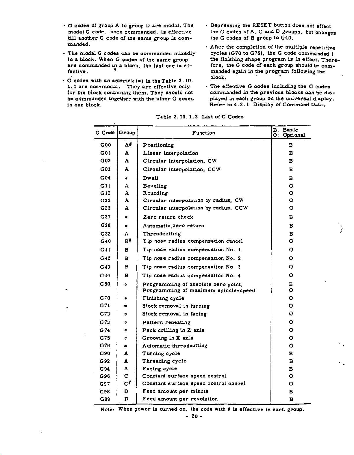
•
G
modal
till
manded.
The
•
In
are
fective
•
G
1.1
for
be
in
codes
of
codes
code,
G
another
modal
a
block.
commanded
G
.
with
are
non-
the
block
commanded
one
block.
group
once
G
code
codes
When
in
an
asterisk
modal.
containing
together
A
to
group
commanded,
of
the
can
G
codes
a
block,
They
D
same
be
commanded
of
the
the
(«)
in
are
them.
the
with
are
is
group
same
last
Table
the
effective
They
other
modal.
effective
is
mixedly
group
one
should
G
The
com¬
is
2.
only
codes
ef¬
10.
not
•
Depressing
the
G
the
G
•
After
cycles
the
finishing
fore,
manded
block.
effective
The
•
commanded
played
Refer
codes
codes
the
completion
(G70
G
the
again
each
in
4.3.
to
RESET
the
ofA,C
B
of
G76),
to
shape
code
in
G
the
in
group
Display
1
group
program
oif
each
the
codes
previous
button
D
and
to
of
the
the
G
group
program
including
on
the
of
does
groups,
G40.
multiple
code
commanded
is
In
shouid
following
the
blocks
universal
Command
not
but
repetitive
effect.
G
can
Data.
affect
changes
There¬
be
com¬
the
codes
be
dis¬
display.
i
G
G44
G50
G70
G71
G72
G73
G74
G75
G92
G94
G96
G97
G98
G99
Code
GOO
G01
G02
G03
G04
Gil
12
G
G22
G23
G27
G28
G32
G40
G41
G42
G43
G76
G90
Note:
Group
A#
A
A
A
*
A
A
A
A
a
*
A
B#
B
B
B
B
»
*
*
w
»
*
«
A
A
A
C
C*
D
D
When
Positioning
Linear
Circular
Circular
Dwell
Beveling
ounding
R
Circular
Circular
Zero
Automatic
Threadcutting
Tip
Tip
Tip
nose
Tip
nose
Tip
Programming
Programming
Finishing
Stock
Stock
Pattern
Peck
Grooving
Automatic
ur
T
aing
Threading
Facing
Constant
Constant
Feed
Feed
power
is
Table
interpolation
interpolation,
interpolation,
interpolation
interpolation
return
nose
radius
nose
radius
nose
radius
radius
radius
removal
removal
repeating
drilling
in
cycle
cycle
surface
surface
amount
amount
turned
2.
10.
1.
Function
check
.zero
return
compensation
compensation
compensation
compensation
compensation
absolute
of
of
maximum
cycle
in
turning
in
facing
Z
in
axis
X
threadcutting
cycle
speed
speed
per
minute
revolution
per
the
on,
20
-
2
axis
List
code
-
of
G
CW
CCW
radius,
by
by
radius.
zero
spindle-speed
control
control
with
Codes
CW
CCW
cancel
No.
No.
No.
No.
point,
cancel
Is
I
1
2
3
4
effective
Basic
B:
Optional
O:
B
B
B
B
B
O
O
O
O
B
B
B
O
O
O
o
O
B
O
O
O
O
O
O
O
O
B
B
B
O
o
B
B
each
in
group.
Page 29

2.10.2
POSITIONING
(GOO)
GOO
This
rate
tem
(U,
by
X(U)
command
the
to
set
W)
•
Independently.
.
•
GOO
GOO
shown
As
incremental
and
edly
commanded
the
For
machine,
the
X
•
•
U
manual.
dependently,
linear.
+X
•
by
from
•
• •
above,
rapid
Since
•
point
the
W
•
Z
refer
the
Z
.
Z(W)
moves
(X,
G50
the
•
•
•
*
absolute
coordinate
in
traverse
a
tool
tool
•
•
a
tool
Z)
in
command
present
•
or
*
a
block.
rate,
to
the
machine
is
moved
path
X
•
*
at
rapid
coordinate
the
moves
or
point
coordinate
values
as
it
on
is
generally
w
s
traverse
for
each
values
can
depends
tool
each
s
sys¬
away
it
axis
be
mix-
upon
builder's
axis
non¬
U/2
in¬
2.10.3
.
GOl
A
line
code
moved
F
ing
causes
by
tool
at
code
the
the
LINEAR
X(U)
•
movedtothe
is
the
traverse
coordinate
the
in
away
must
GOl
a
format
code
F
+x
r
4
5
2.
rate
W)
the
previous
tangential
l—
10.2.2
...
point
system
from
<|i30
Fig.
INTERPOLATION
Z(W)
•
-
(U,
by
specified
be
in
or
error.
is
the
Vi
•
(GOl)
F
•
(X,
designated
set
the
present
in
Feedrate
the
block
biock.
feed
»
•
Z)
on
by
G50
by
contain¬
If
designated
rate.
a
straight
the
point.
not,
F
or
it
Note:
GOO
required
for
When
should
tool
EXAMPLE
X6000
G50
GOO
T0101
|(G00)
X3000
I
for
offset
S
T,
be
put
designation
the
motion.
ZSOOO
S500
500
Z
Fig.
or
in
M03
M
the
*
*>1
2.
code
«
•
•
10.2.
block.
.
«
GOO
in
.
1
commanded,
is
The
of
tool
GOO
tion
rate
can
traverse
for
of
for
be
positioning.
G
code
designa¬
traverse
tool
omitted
the
is
rate
offset
G50
GOO
GOT’ZO
(2
S-i
X10000
T0202
X3500
FI
X6000
POSITION
PROGRAMMED
/
2
rl
£
Fig.
Z
6000
M03
S600
Z500
s
00
»
F20
»
PRESENT
\
TOOL
2.
10.3.
POSITION
1
K
-
*
«
*
21
-
Page 30

2.10.4
CIRCULAR
INTERPOLATION
(G02ÿ
G03)
G02
Fig.
+X
&
s
2.
*35
10.3.2
Circular
clockwise
*60
hi
>3
interpolation,
Table
G02(G03)
A
tool
ter
The
dinate
present
an
by
•
The
are
2.
10.4
Meanings
X(U)*
Is
moved
away
is
end
circular
theFcode.
meanings
shown
from
point
system
position
arc
below.
+X
of
of
•
*
on
the
set
by
at
G02,
o
Z(W)-..
the
the.
arc
hy
(U.
the
circular
present
is
GSO
W).
traverse
G03
CO
2
I*
•
position
(X,
op
A
and
.
K-
Z)
away
tool
rate
each
arc
•
•
whose
in
the
from
moves
specified
address
F-
by
.
.
*
cen¬
K).
(I,
coor¬
the
along
03
G
X(U)
Z(W)
I
K
point
point
to
arc
to
arc-center
interpolation,
of
value)
of
arc
from
center
value)
from
Circular
counterclockwise
End
(Diameter
End
Distance
arc
(Radius
Distance
arc
arc
start
start
on
on
on
on
X
Z
point
X
point
Z
axis
axis
axis
axis
o
G03
POINT
END
+x
of
4
of
w
Z
/
START
POINT
22
-
Page 31

+X
'it
xn
z
END
POINT
w
Fig.
CEHTtR
START
10.
2.
t
POINT
4.
the
code
F
for
G02
in
-Y
system,
.beginning
rotation
is
represented
C02
is
a
Clockwise
direction
the
tool
of
point
the
in
plane
in
+Z
•
The
tangential
The
•
is
defined
"When
right-handed
the
moves
the
Therefore,
{-X.Z
Inversely.
feedrate
direction
viewing
clockwise
arc."
plane)
commanded
feedrate.
the
of
follows.
as
the
coordinate
direction
the
of
Fig.
X-Z
from
of
arc
plane
the
2.10.4.3
by
of
o
1
O
.
Circular
rant
EXAMPLE
Arc
center
coordinates
I
K
The
above
G01
|G02
interpolation
can
be
460
case
Z-
•
X6000
programmed
28R
2.10.4.2
Fig.
100
,/
-
-19.596
•
can
be
programmed
•
F
•
Z-4660
12000
an
of
in
\
V
(10000,
60
-
2
282
*
K-1960
K
-
arc
a
27
202
on
single
-2700)
-
F
multiquad¬
block.
'
+x
4100
20
mm
J~3%4
-19.60mm
follows.
as
•
•
•
f
-Y''
Fig.
2.
10.4.3
of
When
the
alarm
follows.
of
Note
shaded
tool
end
the
circumference
is
not
The
arc.
A
%
that
if
the
area,
continue
will
point
displayed
mark
Fig.
end
the
alarm
to
arc
specified
c
2.
point
is
move
not
is
by
and
the
indicates
CENTER
ARC
10.4.4
is
designated
not
displayed
endlessly.
designated
radius,
the
tool
path
the
k
w
in
end
and
is
the
on
the
as
point
the
1
23
-
-
Page 32

end
The
•
commanded
applied
the
tool
recommendable
la
digit
of
tions
over
•
Although
quadrant
designated
be
EXAMPLE
X(a)
GOO
X(a)
G02
the
In
signation
polation
can
be
than
least
and
point
point
the
to
may
least
1/2
the
can
Z(b)
Z(b)
above,
as
without
executed
input
the
coordinate
when
nose
tip
move
not
input
as
circular
be
done,
for
*
I-
•
the
the
completion
tool
if
increment,
start
1
should
the
circular
radiua
properly.
to
calculate
increment
one
and
disregard
Interpolation
a
closed
interpolation.
•
motion.
is
INPUT
F-
will
a
See
•K*•
control
there
point.
LEAST
be
precisely
Interpolation
compensation,
Generally,
to
the
up
and
count
the
on
circle
•
(Designation
•
*
of
circle)
regard
of
circular
The
program
longer
between
distance
the
Fig.
2.
INCREMENT
next
frac¬
rest.
multi-
cannot
closed
the
Inter¬
end
10.
OR
de¬
4.5.
is
or
it
ICRE
Table
mm
0.
01
999.999
Least
Since
cutting
workpiece
function
v
2.10.5
Maximum
Metric
0.
001
sec
command
motions
block
at
feed
is
rounded
prevents
me
ROOT®
SJITHOUT
"KIDDLE"
WITH
COMMAND,
TAPE
of
mm
Error
Dwell
increment
are
Detect
or
controls
DWELL
DWELL
AND
Programmable
Time
inch
0.001
999.
smoothly
Off,
a
little
bit.
the
\y_
OR
”0"
WITH
DWELL
TIME
"LONG"
Inch*
0.0001
999
sec
connected
corner
the
The
rounding.
TIME
DWELL
Value
I
Inch
j
In
of
dwell
TIME
Fig.
rule
This
pensated
compensation.
2.10.5
.
G04
This
ified
DWELL
U
command
by
programmed
structions
•
The
maximum
address
2.10.4.5
also
by
•
•
the
.
is
U
applies
the
operation
04)
(G
«
stops
address
a
in
duration
shown
Designation
to
feed
U.
without
block
time
below.
the
of
for
Dwell
of
Circle
circular
nose
tip
duration
the
should
the
specified
arc
radius
be
other
by
com¬
spec¬
solely
in¬
the
NOTES:
Since
•
only
•
No
ing
G01
G04
G01
(dwell)
G04
the
for
command
G04
the
W-100
U200
W-100
0.2
±L
(CHIP
block
.
F2S
«
«
Fig.
should
SEC
DWELL
CUT)
10.5
2.
non-
is
containing
be
put
«
TIME
modal,
in
Feed:
Dwell
0.2
Feed:
It.
the
sec
It
block
1mm
time:
1mm
effective
is
c
contain¬
-24-
Page 33

2.10.8
Beveling
1.
CORNERING
(G
X(U)
Gil
{
Z(W)
GU
L
11)
•*•
.
Beveling
X(U)
END
POINT
(Gil,
K
.
.
1
•
*
K-
.
\
%
45*
*
+z
12)ÿ
G
•
•
for
K
*ÿ
0/2
START
POINT
•
F
•
axis
X
•
F
•
*
X
(DIAMETER)
•
•
*
Table
*
2.10.6.1
This
command
workpiece.
specified
Meaning
Z(W)
Gil
Addresses
simultaneously
of
each
Beveling
...
END
POINT
•W7
removes
address
for
Z
I
• •
*
o
the
and
X
in
is
axis
F
START
sharp
Z
a
block.
shown
•
•
POINT
corner
cannot
below.
*
of
be
Beveling
the
following
|K|
The
command
format
When
display
completion
the
played
<
error.
Gil
again.
K
values
|U/2|
command
G
for
t
(K
values.
exceeding
code
of
L—
and
is
the
Beveling
I)
the
starts
changed
execution,
are
HI
above
to
Value
Direction
limited
<
executed,
be
to
G01.
GU
within
|w|
value
is
causes
the
After
dis¬
©
©
K
t
GOO
Gil
(Gil)
.
X3000
Z-2000
X8000
1
,*80
'Beveling
(Radius
-Beveling
Z0
K-700
7
1800
20
2
*
,
Value
Value)
Direction
F30
«
+X
*30
I
*
Fig.
2.
25
-
-
10.6.
1
Page 34

)
2.
Rounding
12
G
!
t
(G
fX(U)
\
(Z{W)
G12
ex
L
K
T
12)
•
. .
Rounding
X(U)
END
POINT
+Z
t
•
• •
-
‘
-
K
•
I
•
•
K-
o
START
Rounding
Rounding
•
'
'
• •
•
for
X
•
K
K*
rrr
U/2
POINT
)
F
J
axis
•
F
•
I
x
I
DIAMETER)
value
direction
Z
X
in
axis
*
o
the
and
a
block.
F
START
POINT
rounding
Z
cannot
Meaning
•
•
The
#
be
corner
of
of
spec¬
each
the
command
This
corner.
simultaneously
2.
ified
is
address
10.6.2
G12
rounded
Rounding
Z(W)
END
iI+
is
L
•
•
*
Table
•
•
perform*
Addresses
a
quadrant.
to
shown
for
...
I
POINT
below.
•
n
7
t
K
-
'
w
Rounding
Rounding
value
direction
Rounding
following
the
|K|
command
The
causes
G12
When
played
G02
and
rounding
After
arc.
is
G12
GOO
G12
Q
(G
|
©
values
<
format
command
while
or
G03
direction
the
displayed
X2000
Z-2S00
12)
X7000
70
*
(K
values.
|U/2|
exceeding
error,
tool
the
is
completion
again.
Z0
6
I)
and
executed,
is
moving
displayed
while
along
a
F30
1900
K-600
25
limited
are
HI<iwl
above
the
on
depending
of
the
*
F20
+X
G01
the
circular
the
execution,
»
value
linear
within
is
on
dis¬
line,
the
NOTES
•
Since
group
G
•
X
ously
containing
mat
codes
and
error.
Gil
A,
Z
in
and
they
of
group
axes
Gil
addresses
G12
are
cannot
or
A
12
G
are
modal
retained
are
specified.
be
specified
command.
of
both
until
axes
G
codes
the
simultane¬
The
other
block
causes
of
for¬
EXAMPLE
.
•
G12
The
•
which
ed.
"
tive
command.
•
*
can
mands
through
X-
block
The
Tip
for
The
be
•
and
l
nose
block
specified
of
G73).
W.
•
without
tool
the
multiple
.
are
K
may
radius
blocks
including
•
K
•
and
I
zero,
not
compensation
including
the
in
repetitive
•
*
K
should
move
Gil
finishing
or
the
properly.
Gil
or
cycles
block
not
or
G
12
shape
in
issu¬
be
is
effec¬
G12
command
com-'
(G70
Fig.
4>n
2.
10.6.2
*z
-
f
*
26
-
Page 35
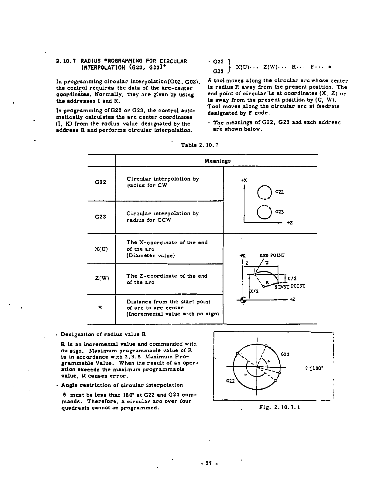
2.10.7
RADIUS
INTERPOLATION
In
programming
control
the
coordinates.
the
addresses
In
programming
matically
K)
(I,
address
from
R
PROGRAMMING
circular
requires
Normally,
I
and
ofG22
calculates
the
radius
and
performs
the
K.
or
the
value
FOR
(G22,
G23)
interpolation
data
of
the
are
they
G23,
the
arc
center
designated
circular
CIRCULAR
+
(G02,
arc-center
given
by
using
control
coordinates
by
interpolation.
G03),
auto¬
the
•
C22
1
f
G23
J
A
tool
moves
is
radius
end
point
is
away
moves
Tool
designated
meanings
The
•
shown
are
X(U)-..
R
of
from
along
away
circular'll
the
along
by
code.
F
of
below.
Z(W)...
the
from
present
circular
the
G22,
circular
the
present
at
coordinates
position
G23
R-..
and
arc
arc
by
each
F*
•
whose
position.
(X,
(U,
at
feedrate
address
o
center
Z)
W).
The
or
G22
G23
X(U)
Z(W)
R
Circular
radius
Circular
radius
The
of
(Diameter
The
of
Distance
of
(Incremental
for
for
X-coordinate
the
arc
Z-coordinate
arc
the
arc
to
Table
interpolation
CW
interpolation
CCW
of
value)
of
the
from
arc
center
value
start
with
the
the
by
by
end
end
point
no
2.
10.7
Meanings
sign)
+X
+X
o®
Ow
END
/w
7
1
X/2
POINT
START
+Z
U/2
P0i:rr
Designation
•
an
is
R
no
sign.
is
in
grammable
ation
value,
Angle
•
6
must
mands.
quadrants
of
incremental
Maximum
accordance
Value.
exceeds
it
causes
restriction
less
be
Therefore,
cannot
radius
the
than
with
maximum
error.
of
be
R
value
commanded
and
value
programmable
2.3.5
When
Maximum
the
result
programmable
circular
180*
a
circular
interpolation
G22
at
programmed.
arc
and
value
of
G23
over
Pro¬
an
with
of
R
oper¬
com¬
four
-
27
-
C22
Fig.
t
C23
2.10.7.
i
*180*
r
.
I
I
Page 36

+X
END
POINT
O-"'
180*
OR
BELOW
ARC
I’gW'ITR
R
•
la
is
should
When
•
fixed,
circular
the
aot
R
or
G22
contained
be
not
is
varied
the
tool
arc.
mode,
G23
1s
or
R
commanded.
both
at
move
will
the
block
designated
and
start
along
the
in
which
to
zero
end
points
following
R
END
POINT
*4.
‘D/2
y'
W
Fig.
CENTER
/
3'
52.5
2.
10.7.2
R
START
START
UNT
POINT
+X
*40
+Z
+Z
Therefore,
not
does
(Distance
<
R
Tip
+
block
the
t
•
The
signated
ple
repetitive
2.10.8
This
function
so
that
fixed
the
exist
nose
block
ZERO
the
original
the
in
which
between
radius
containing
containing
in
finishing
cycles
RETURN
checks
machine
END
CENTER
*3
START
following
causes
start
compensation
G22
shape
(G70
CHECK
that
starts
point.
POINT
h
POINT
case,
data
point
2
or
G22
to
the
from
the
error.
and
is
G23.
G23
or
commands
G73).
(G27)
program
and
arc
end
effective
can
of
is
returns
center
point)
be
multi¬
made
for
de¬
to
(T)
Note:
NOTES:
•
G22
until
med
X4000
G01
(X4000)
j
G22
Parenthesized
case.
this
in
and
the
are
G23
otherGcode
.
Fig.
Z-1000
Z-5250
modal.
2.10.7.3
F20
commands
They
group
of
*
R3000
can
are
A
(F20)
be
retained
program¬
is
«|
omitted
-
28
•
•
#
-
G27
After
(X,
the
point
When
point
position
for
continued.
meet
code
displayed
ped.
When
position
point.
follows
X(U)
positioning
Z)
or
position
or
not.
the
position
ZERO
meets
axes,
both
with
,,24"
(The
G27
will
Tool
when
"Automatic
TAPE,
MDI
•
• •
incremental
the
is
checked
RETURN
with
the
When
the
fixed
(the
zero
and
the
CYCLE
is
commanded
not
offset
G27
operation"
or
Z(W)
the
at
meets
the
automatic
either
original
return
automatic
START
meet
mode
commanded.
is
MEM
•
•
absoiute
it
if
with
lamp
fixed
of
in
with
should
means
mode
coordinates
coordinates
is
the
fixed
the
is
lit.
original
operation*
axes
the
point,
position
operation
la
lamp
offset
tool
fixed
the
be
operation
this
in
(U,
fixed
original
original
When
point
will
does
alarm
the
error)
is
turned
mode,
original
cancelled
manual.
W),
the
not
is
stop¬
off.)
in
as
be
as
the
«
Page 37

To
cancel
containing
TOO00
U
G27
To
cancel
taining
G27
U
NOTE:
finite
position
returned
Automatic
or
is
represented
.
-
G27,
•
-
The
by
tool
G27,
.
tool
•
fixed
the
offset
*
W
offset
W
on
manual
Zero
by
.
•
•
•
original
the
Return
mode
*
mode
•
TOn00
machine
Zero
in
prior
the
in
*
point
means
where
Return
command
this
manual.
the
to
block
the
operation
(G28).
block
con¬
the
tool
de¬
It
When
*
the
tool
celling
la
G28
offset
motion.
ia
commanded
finally
ia
iceinomMs
nut
tom
z
,
1
tool
In
cancelled
'
/
/
r
f-,
—
—
pi'
x/2
offset
without
nxn>
wax
I
I--Z
\
too
(OTION
mode,
aeisnut.
“SO-
UTCZM
can¬
--
2.10.9
•
G28
After
absolute
coordinates
performed
After
POSITION
completion
automatic
For
•
the
in
fixed
the
Zero
not,
tioning
Tool
*
when
To
cancel
containing
G28
cancel
To
containing
G28
NOTES:
The
•
tion
turn.
AUTOMATIC
X{U)
•
positioning
coordinates
(U,
for
the
completion
lamp
of
operation
Zero
Return
area
from
original
Return
the
tool
command.
G28
mode
is
tool
G28,
offset
TOO00
X
•
•
•
tool
G28,
«
•
X
Return
Zero
that
Refer
by
as
ZERO
Z(W)
*
-
two
axes
(X,
W).
the
two
axes
of
of
the
Zero
Return
is
operation,
which
point,
limit
switch
can
be
moved
should
commanded.
mode
offset
«
Z
•
-
mode
offset
.
.
Z
•
motion
operating
6.2.1
to
RETURN
...
*
simultaneously
Z)
or
the
Zero
Return
simultaneously.
Zero
Return,
is
axis
continued.
the
for
tool
e.g.
is
to
be
cancelled
prior
lit.
both
the
can
the
not
the
*
in
the
TOCJ00
means
Manual
the
Manual
Zero
(fi28)
incremental
motion
ZERO
After
axes,
should
tool
return
area
operated.
area
as
to
the
block
*
same
the
Zero
Return.
the
where
by
posi¬
follows
block
mo¬
Re¬
at
the
to
If
be
the
is
2.10.10
cut
by
X(U)
by
shown
thread,
coordinates
Straight
are
G32
•
Threadcutting
ified
solute
dinates
Programmable
are
Fig.
2.10.9.
T
—
Fig.
A
i'
G28
100
zoo
X40000
THREADCUTTING
taper
thread
G32
command.
Z(W)
•
•
the
(U,
•
is
RorE
W).
lead
below.
•
performed
code.
Z)
(X.
ranges
1
y,
*
"
SIA1T
ronrr
Z30000
2.10.9.2
(G32)
and
C
-
\E
in
The
or
incremental
of
F
the
end
F
ran
Tonrr
*
»_
zoo
MIHUM
scroll
•
•
and
oaicutu.
//
T030Q
.
•
i
lead
point
E
TO
iztuss
thread
spec¬
is
codes
301
MCA
«
I
ab¬
coor¬
29
-
Page 38

Table
Programmable
10.
1
10.
2.
Lead
Range
Metric
F
E
•
The
Inch*
code
code
direction
Limitation
•W
is
is
<«.si
n
Format
F2.2
E2.4
FI.
El.
for
for
4
6
normal
precise
lead
of
Table
of
Taper
+X
Programmable
F9999
to
FI
to
E999999
El
F39366
to
FI
E3936600'
to
El
threadcutting.
threadcumng.
specified
10.
2.
Angle
a
a
by
10.2
<
45*
45*
>
r
I
I
Z
52
Range
and
F
Direction
Lead
Lead
END
POINT
a
w
0.01
0.0001
0001
0.
0.000001
E
codes
of
Direction
the
m
the
in
-V
Si
to
is
Lead
direction
direction
i
i
t
t
1
I
Meanings
99.
99
99.9999
to
3.9366
to
3.936600
to
shown
of
0/2
X/2
\
START
mm
below.
Lead
of
of
POINT
mm
Inch
Z
X
+z
inch
axis
axis
•V
•
Command
Straight
Thread
Taper
Thread
Scroll
Thread
format
Type
threadcutting
of
Normal
Precise
Normal
Precise
Normal
Precise
Fig.
Table
-30-
C32
C32
G32
C32
G32
G32
(Usd)
L
1
10.
10.
2.
is
shown
10.
2.
Z(W)
Z(W)
X(U)
X(U)
X(U)
X(U)
below.
10.3
Command
...
•
•
•
•
•
•
•
•
format
.
F
-
E
•
•
*
...
Z(W)
•
...
Z(W)
•
F
•
•
-
-
E
•
F
•
•
*
•
.
E
•
*
*
«
Page 39

I
I
NOTES:
Allowances
•
cutting
starting
because
+
and
5j
error
are
required
occurs
end
and
lead
points.
r
i
|ÿJÿUAAAJ\AAAAA7\A,ÿ
m
twwwww>
I
—
Fig.
2.
10.
10.2
&l
+x
near
y
i
i
1
for
thread¬
the
+z
r
I
I
MAAAAAMAA
I£2|
•
•
•
spindle
If
cutting,
lag,
servo
Chamfering
*
necessary,
If
manded.
following
The
threadcutting
•
Feedrate
.
Feed
G32
The
mode.
G98
displayed.
be
Dry
In
•
rate.
©
speed
leads
the
for
Override
operation
Hold
command
If
Run
mode,
.1
i2L
to
is
not
become
thread
(or
G12
operation
including
should
commanded,
the
20
+z
constant
incorrect
not
is
G76t
is
disregarded
2,
G3
.
•
•
not
the
tool
moves
during
effective
)
should
andG76+.
G92
Regarded
be
commanded
alarm
at
due
be
Jog
thread*
to
at
G32.
com¬
during
as
I0Q°«
'*14"
feed-
the
in
will
Thread
Cutting
lead
depth
i
-
2.10.
Fig.
5.0
L
i
i
*
6*
*
1.0
5.0
3.0
mm
mm
mm
mm
<D
©
10.3
GOO
G32
GOO
G32
GOO
60
U-4200
W-6800
U4200
W6800
U-4400
W-6800
U4400
*
F500
»
«
*
*
«
*
i
31
-
-
Page 40
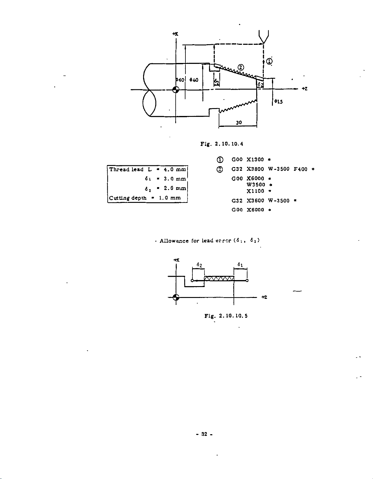
Thread
Cutting
Lead
depth
L
6
«1
_y
44
X1300
X3800
X6000
W3500
X1100
X3600
X6000
i
i
_
i
CD
•
i
i
i
*
W-3500
*
*
*
W-3S00
*
015
F400
»
+z
*
f
i
i
.©
$40
>60
y
v>ÿ
30
10.4
2.10.
Fig.
GOO
©
mm
4.0
*
3.0
1.0
2.0
mm
mm
mm
»
*
«
*
©
G32
GOO
G32
GOO
•
Allowance
&
+X
for
lead
<52
Fig.
error
2.
10.
1
(6i,
«1
10.
<5*)
o
+z
5
-32-
Page 41

and
following
are
4
2
equation.
obtained
Table
approximately
10.4
2.
10.
from
the
Si
6
2
St
a
1
(ln-j-
EXAMPLE
Lead
Spindle
Thread
6
-
1
>
1)
>
L-S
of
speed
accuracy
Equation
L-S
K
60-
60-K
1/50
2.91
thread
(In
-
—
a
1/100
3.61
L
*
S
*
«
a
1)
mm
3.0
500
rpm
1/100
(mm):
L
(rpm):
S
K:
(-):
a
In:
1/150
4.01
Leadofthread
Spindle
Constant
Accuracy
Natural
1/200
4.29
Meanings
speed
(Normal
of
L
d
•••
L
logarithm
value:
thread
Lead
(loge
1/250
4.52
30)
error
)
1/300
4.70
Si
Si
3.0
500
33
x
60-
K
0.
-
>
L-S
>
60-K
a
3.0
‘
60-K
*>
x
500
-
83
mm
x
3.
61
!»
3.0
mm
Page 42

2.10.11
Because
a
deviation
actual
are
not
The
tip
the
problem
TIP
(G40
of
curve
enough
nose
NOSE
THROUGH
a
nose
between
produced.
for
radius
nose
of
RADIUS
G44>
radius
taper
of
the
desired
Therefore,
and
compensation
radius.
COMPENSATION
+
lathe
curve
circular
See
tools,
option
Fig.
there
and
tool
cuttings.
resolves
2.
the
offsets
10.
11.
2.
10.
radius
nose
11.
0
to
must
1
Incht
0.
values
9999
be
ALL
INSERT
set
inch
without
ROUND
Table
Metric
is
0
C.
1.
Setting
Radius
•
signs.
999
to
24.
of
tip
value
mm
nose
of
tip
fOttlOW
ixrr
I
CHOI
arrmc
COKTOJR
WITHOUT
EAOIUS
1.
Tip
A.
B.
/
x
HOSE
TIP
COtfffifSATXON
nose
Radius
nose
Tip
storage
sation
can
be
machine.
the
2
T
T
4-digit:
Value
to
.
Refer
Range
Radius
range.
nunuuMD
.comae
Sosz
RADIOS
Fig.
radius
value
radius
before
is
commanded.
written
di
git:
-
Fig.
nose
of
tip
value
TOO:,
R03Z
\
annus
coinoua
2.
values
storage
value
the
in
9
sets
16
2.9.3
can
MIS
cnin
COWVSATXOM
RADIOS
am
TOOL
WITH
TIF
RADIUS
•3ATI0K
/
/
'T7
comma
TIF.
WITH
COKKHSATIOir
10.
11.
must
nose
tip
Number
the
storage
32
or
sets
Storage
set
values
within
radius
be
MITSOTT
MTH
l«WZ
COHTZM-
1
be
radius
depends
of
TIF
3
written
of
Tool
the
*
t
TOOL
sosz
TIF
in
compen¬
that
pairs
upon
Offset
following
cram
a
the
2.
T
T
11
V*
M
For
radius
Writing
character
code
The
must
DDIX)
t
If
the
writing
compensation,
of
Tool
is
designation
T
be
for
code
programmed
L
Offset
offset
compensation
Tool
•Direction
compensation
Right
side
tool
of
Left
side
of
tool
Fig.
R.
(In
travel
travel
raiuju.
TXT
2.
of
radius
Offset
nose
tip
the
number
and
number
viewed
viewed
10.
case
of
XQSZ
11.2
refer
Value.
radius
with
tip
tip
in
in
values
sign
of
for
nose
the
the
'"'N
yv
to
Fig.
The
compensation
(ÿ*ÿ
4-digitl
T
tool
radius
nose
direction
direction
for
address
or
position
radius
tip
4.3.6
-)
nose
34
-
Page 43

'TV
C42
C41
B.
Before
changed
and
the
the
direction
changed.
for
of
of
sign
+z
the
G40
nose
tip
sign
turning
tool
motion
compensation
of
T
•HC
/
£
direction
from
should
radius
changed
is
the
of
For
and
code.
7
Fig.
2.
to
be
compensation
instance,
for
changes,
should
k
10.
11.3
of
compensation
or
to
+,
-
-
programmed
compensation.
without
facing,
the
be
RIGHT
COMPENSATION
T
to
cancelling,
will
a
when
SIDE
tool
as
the
correct
programmed
(T+)
SIDE
LEFT
COMPENSATION
R
is
QQOO
cancel
if
Even
the
not
be
is
used
direction
direction
with
(T-)
-G
Regardless
compensation,
virtual
the
POS
Issue
B.
pensation
Cautions
C.
(l)
Since
group,
code
of
G41,
must
sation.
&
C43
Fig.
of
tool
tip
pushbutton.
to
G40
G40
is
be
cancel
in
programming
to
they
are
commanded.
G42,
intermediated
TOOL
CJU1LU
the
the
is
G44
G43
TOLIDAL
TOOL
I
R
C44
10.
2.
mode
current
displayed
the
are
modal
retained
Before
G44
and
11.5
of
tip
to
Tin
tip
position
by
nose
G
code
G
until
to
cancel
radius
nose
of
depressing
radius
codes
the
other
switching
another.
the
the
com¬
of
B
G
one
G40
compen¬
3.
G
G
A.
(G41
One
grammed
radius
specify
tool
code
code
designation
of
tip
G44)
to
of
tip
G42,
G41,
before
compensation.
the
relationship
and
the
Fig.
nose
the
tool
2.10.
(G40
radius
G43
7
11.4
to
and
execution
These
center.
+z
G44)
compensation
G44
of
four
between
should
tip
G
the
be
nose
codes
virtual
pro¬
GA2
\
\
H
&
“°1
11.6
in
044
|
[
with¬
block.
the
solely
same
C43
Fig.
(2)
35
-
-
G40
out
to
the
G44
other
must
10.
2.
be
command
programmed
Page 44
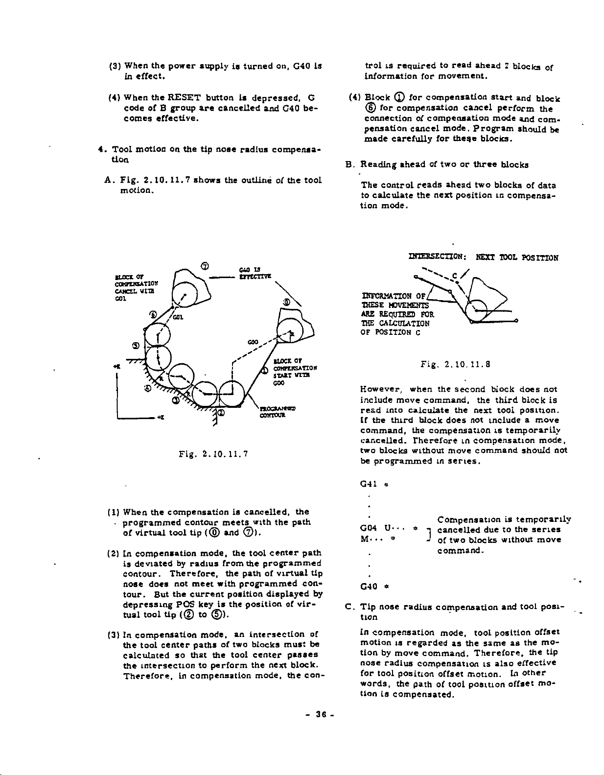
(3)
When
effect.
in
the
power
supply
is
turned
on,
G4Q
read
movement.
for
to
ahead
2
blocks
of
trol
is
is
required
information
(4)
Tool
4.
tion
Fig.
A.
motion.
BLOCK
COKTCMATIDlt
CAMCSL
sat
When
the
of
motion
2.
B
effective.
10.
code
comes
or
ura
'©ÿ''ÿGOl
/
f
©
I
RESET
group
on
the
7
11.
/
Fig.
button
are
tip
shows
<Z>
s/s
2.
cancelled
nose
the
r
J
f
10.
11.
is
depressed,
radius
outline
u
cm
tmcroji
COO
s'
S’
•F*0G*Af*«X>
CUH1WK
7
and
G40
compensa¬
of
the
3>
or
BLOCK
COtffEKSATIOK
WITH
STABT
GOO
G
be¬
tool
(4)
Block
(D
connection
pensation
made
B.
Reading
The
to
calculate
tion
INFORMATION
THESE
ARE
THE
OF
POSITION
However,
include
read
the
If
command,
cancelled.
two
be
programmed
(£)
for
compensation
for
compensation
of
compensation
cancel
carefully
of
ahead
control
reads
the
mode.
INTERSECTION
o-c/
OF/__
MOVEMENTS
REQUIRED
CALCULATION
into
third
blocks
when
move
calculate
FOR
C
Fig.
command,
block
the
compensation
Therefore
without
mode.
for
two
next
the
in
theqe
or
ahead
position
\
10.
2.
second
the
does
move
series.
cancel
Program
blocks.
three
two
:
NEXT
11.8
the
next
include
not
in
compensation
command
start
perform
mode
blocks
blocks
in
compensa¬
IDOL
a
block
third
tool
temporarily
is
and
block
the
and
com¬
should
of
data
POSITION
does
not
block
position.
a
move
mode,
should
be
is
not
(1)
When
programmed
-
virtual
of
(2)
compensation
in
deviated
is
contour.
nose
tour.
depressing
tual
(3)
compensation
In
the
calculated
the
Therefore,
the
compensation
tool
Therefore,
does
But
tool
tip
tool
center
intersection
contour
tip
mode,
radius
by
not
meet
the
current
POS
key
(©
to
mode,
paths
so
that
to
compensation
in
(®
with
is
©).
the
perform
cancelled,
is
meets
©).
and
tool
the
from
the
the
path
programmed
position
the
position
an
intersection
of
two
blocks
tool
the
with
center
programmed
virtual
of
displayed
of
must
center
the
mode,
passes
next
the
path
vir¬
block.
the
path
tip
con¬
by
of
be
con-
36
G41
«
temporarily
G04
M-
‘
]
Compensation
cancelled
of
two
blocks
•
U-
•
•
•
*
due
is
the
to
without
series
move
command.
G40
*
C.
Tip
tion
In
motion
tion
nose
for
words,
tion
nose
radius
compensation
is
regarded
by
move
radius
tool
is
compensation
position
the
path
compensated.
compensation
mode,
as
command.
offset
of
tool
tool
the
same
Therefore,
is
motion.
position
and
position
as
also
In
offset
tool
posi¬
offset
mo¬
the
the
effective
other
mo¬
tip
-
Page 45

Programming
S.
ompensation
c
The
tip
when
the
for
Compensation
A.
Use
is
nose
tool
offset
compensation
the
following
switched
procedure
radius
number
start
to
G41.
G40
)
of
tip
compensation
(T
code)
are
specified.
format
mode
G42,
when
G43
nose
radius
Is
executed
andGcode
G40
the
or
G44
mode
mode.
TOOL
OFFSET
(TOOL
OFFSET
NUMBER
.
06)
«x/2
szswy
+Z
Fig.
(X,
f
j
t
t
/
/
f
s
Z)
POSITIONOFBLOCK
10.
2.
11.9
®
(f,
GOO---
G41
G01X(U)-
(1)
Specify
of
(2)
Program
commands
(3)
G01
start
Interpolation
Circular
be
displayed.
NOTE.
The
-G41
GOO
LCOI
*
-
tool
compensation
GOO
or
of
compensation.
used.
following
«ÿ
f~ir~[/\A
T±
-ÿ
-
Z(W)-
G
in
interpolations
If
program
-
number
code
the
must
and
used,
-
mode
solely
GOO
»
F-
same
be
...
Designation
tool
offset
number
----
Or
G42
.
a
•
----
Block
—
pensation
with
G01
code)
(T
is
programmed
is
the
alarm
should
before
programmed.
without
block.
is
G01
positioning.
for
G03)
(G02,
code
avoided.
be
Block
tion
of
start
the
for
for
"15"
compensa¬
to
of
com-
G
other
linear
cannot
or
the
G44
start
code
of
GOO
is
EXAMPLE
G50
GOO
G41
(GOO)
(p
(D
G01
X11000
S600
«
X3000
1800
Z-
M03
1:
Z4000
T0202
Z500
F25
tl
*
«
Compensation
---
*
start
*
&
coo
/
/
i--:-
V
/
/
®
«*
f
I
This
program
pensation
offset,
understand
(T)
(D
(3)
enters
simultaneously
which
makes
actual
the
G41
»
T-0606
G01
G01
X-
--
the
tip
with
a
programmer
motions.
F---
a
Z--
-
nose
the
*
radius
tool
hard
com¬
position
to
37
Fig.
2.10.11.10
-
Page 46

EXAMPLE
G50
GOO
G41
G01
©
<D
Compensation
B.
2:
X8000
S400
Z4000
M03
*
X2000Z700
X5000
*50
Z-
ts
Fig.
T0303
F600
1500
2.
cancel
*
F30
10.
*
*
SOI
11.
Compensation
start
*
<5
XI
NOTE:
The
following
-GOO
T±UDOO
-G40
This
program
pensation
offset
to
©
cancel,
understand
(G41.
G01
G40
+x
program
X-
••
Z
*
*
cancels
simultaneously
which
the
T-0505)
F--.
Z---
T-0500
*
SL
o—
-.
actual
should
*
Cancel
the
makes
tip
with
a
programmer
motions.
be
of
nose
*
*
3a£!
W\
5x/2
avoided.
compensation
radius
the
tool
com¬
position
hard
WhenG41,
G40,
GO
l
G40
.(1)
Program
before
pensation.
(2)
TOO
gether
GOO
interpolation)
alarm
(3)
G40
med
the
G42,
the
to
••
following
G44)
Z(W).
use
(G41
X(U)-
T±oaoo
»
tool
the
the
block
should
(positioning).
(compensation
soiely
same
with
code
be
G01
"15"
without
block.
or
G43
format.
.
.
F-
-
offset
of
G40
programmed
(linear
G02
will
be
be
cancel)
the
cannot
switched
is
G44
•
number
to
interpolation)
and
used.
other
Compensa-
tion
>
with
GOO
cancel
a
in
G03
If
displayed.
must
commands
cancel
G01
(T
00
the
block
(circular
used,
be
program¬
code)
com¬
to¬
or
the
to
CENTER
TOOL
PATH
or
in
EXAMPLE
(G41.
G02
G01
GOO
----
G40
OF
+0202)
T
U200Q
X11000
BLOCX
1
F25
Z4000
F;a'
©
*
fix
2.
10.
T0200
TOOL
(TOOL
NUMBER
12
11
*
OFFSET
OFFSET
05)
Compensation
•••
cancel
38
-
-
Page 47

C,
Programming
compensation
/
u
coo
SOKZ
omrr
TSX
m
m
ts
ramoM
w
TOOL
CAMCZUO.
u
urana
ramcH
<uo.
TOOL.
(1)
Be
careful
cutting
*o)
not
contour.
consideration
mode
to.program
in
wedge-shaped
a
EXAMPLE
T+0303)
(G41,
•
G01
G01
U2400
X3000
G01
G40
*
Fig.
2
F30
Z4000
o
coi
r
2.
F600
il.
JO.
T0300
.
Compensation
•
•
13
cancel
urms
an
W£
or
ROCSAMCS
tenon
orr
fOIWT
unst
comouiNÿL'
AUAY
FAB
is
(a)
Wrong
T+
UKW
nr
or
BOSS
:i
CAB
CCT
vacs
F10C1AK
nr
THAT
CAM
21
WEDCT
nor
W
IS
C£T
THE
(MU
nose
IB
or
THE
so
1
I
I
I
T*
»
(b)
Correct
(2)
Program
nose
2.
tool
10.11.
movement
Fig.
the
diameter
of
2R
can
get
15
so
in
that
the
the
contour.
tip
u
r
nouAMa
comm
?
•*x
Fig.
2.
10.
11.
14
T»
(a)
Correct
Fig.
39
-
-
(b)
Wrong
11.
16
2.
10.
T*
Page 48

NOTE:
When
wrong
tion,
cases.
program
a
operation
usually
Check
it
in
is
the
becomes
tip
nose
caused
program.
by
error
radius
the
causes
or
compensa¬
two
above
Table
6.
A.
2.10.11.2
Precautions
Max
programmable
Max
programmable
compensation
on
nose
tip
shown
radius
value
value
below.
compensation
of
tip
nose
radius
B.
Program
Data
the
(1)
A
sued
compensation
G12,
lamp
(2)
The
blocks
path.
which
error
following
command
the
in
G22
is
Lit..
contour
cannot
(the
or
Length
Linear
Joint
and
Joint
Circular
Note:
cases.
otner
block
cancel.
G23
When
whose
be
of
Circular
between
Above
causes
alarm
than
of
compensation
issued,
is
G
intersection
obtained
Item
of
Interpolation
Linear
Line
Arc
Arcs
figures
data
error
"15")
code
and
GOO
(When
11,
not.)
on
G02,
the
the
are
occurs
is
G01
start
G03,
ALARM
between
tool
for
is¬
or
center
Restriction
(0)
64
*5931.
t
S
<
*8388.
r
(r
-
6
r
and
I
(3)
of
The
for
arc.
Radius
(r)
control
the
in
Tl<2
2965.81
S
2097.
K
specification
following
compensation
of
£
Radius
r
*
*
i
VS/sS/sS/V
mm
(7)
60
mm
)
(8)
mm
15
circular
commanded
of
tip
(0)
A.
for
mm
nose
arc
the
circular
(R)
f
t
is
inside
i
'
commanded
of
circular
arc
i
<•)
error
unzutcnoN
HOT
ts
Fig.
orntics.
2.
10.
11.17
urtzxsccrtON
OITA
SWT
IS
(k)
Crror
DUD.
(4)
Coÿnwcloq
is*
Ida
(a)
Inverse
a
t
circular
Error
or
tor
Fig.
nearly
are
10.
2.
inverse
Coÿanaactoo
oucsld*
(b)
18
11.
cutting
tor
circular
of
Correct
arc
is
pro¬
grammed.
S
v
X
N
B
c
A
(a)
Inverse
40
-
-
cutting
A
Page 49

C
GOO,
(b)
codes
G
a
As
should
Usable
G01,
c
Nearly
rule,
not
G04,
Fig.
usable
G
be
Table
G
Gil
C
Note:
arc.
enoughtoJudge
program
Inverse
in
codes
used
codes
In
tangential
causes
Cutting
10.
2.
11.
compensation
other
the
in
2.
11.3
10.
B
8
the
case
angle
whether
error
of
19
mode
than
shown
compensation
Remarks
A
circular
la
6
the
noc.
or
below
mode
not
D.
Change
As
be
directly
the
tool
However,
(the
0,
Before
the
Refer
NOTE:
funcUons
and
Though
by
.
shaped
tion
change
procedure
cancel.
of
Up
a
rule,
changed
for
old
the
compensation
the
(G41,
nose
Up
number'"02")
offset
when
contents
compensation
the
Up
to
page
When
of
posiUon
tool
the
following
contour
offset
motion.
the
on
T+0202)
nose
tip
In
radius
compensation
example
radius
new
the
of
tool
nose
radius
mode
38.
TtQGoO
nose
Up
offset
compensation
program,
may
radius
page
value
38
radius
nose
value
values
mode.
T±OO02
(the
value
remains
nose
Up
offset
is
occur
It
number
temporarily
value
should
is
commanded,
radius
compensation
are
can
note
duetotool
is
recommendable
after
compensation
for
should
If
TtOCo3,
**
contents
In
radius
"03")
cancelled.
is
changed,
cancelled.
be
cancelled.
be
cancelled
a
that
taking
not
changed
of
effect.
value
is
both
wedge-
posi¬
to
the
G96,
•
G98,
•
12,
G
•••
G70.
•
G97
•
Constant
-
control
G99
•
•
Feed
G22,
Command
circular
G71,
••
Multiple
;
No.
function
G23
G72,
1
2
3
4
S
6
surface
including
arc
G73
repetitive
Command
i
Command
j
Command
Tt
Commands
G27,
Command
speed
designation
cycle
of
two
M01
of
of
tool
(Note)
00
Q
of
G50,
G74,
of
M02
Inhibited
the
compensation
cancel
start
Commands
blocks
or
offset
the
following
G75,
or
block
M02
G76,
M30
in
of
or
without
number
G
G90,
Table
Operations
or
move
whose
codes:
2.
G92,
Inhibited
E.
When
Table
pensation
led
11.4
10.
command
contents
G94
T+0200
T+0203
the
2.10.
temporarily
or
in
are
»
••
•••
*
commands
commands
11.4
mode,
series
0
Cancel
offset
Tool
becomes
and
or
are
performed
the
compensation
cancelled.
I
Compensation
Temporary
cancel
of
compensation
number
effective.
operations
operations
in
listed
the
is
03
in
com¬
cancel¬
7
8
9
Note:
CommandofG28
Reset
Power
When
can
operation
off
operation
compensation
the
programmed.
be
is
cancelled
by
41
G40
-
Cancel
next
block,
in
the
*
this
command
Page 50

Inhibition
F.
(X)
Operation
formed
through
pressed,
effective
becomes
(2)
G40
operation
EXAMPLE
(G99)
(J)
G50
®O.0
G4
©
(GOO)
©
G01
G12
Gil
G01
G22
GO
G04
(G01)
G00
0
G40
0
in
G44).
through
X14000
«...
1
ZO
X2000
Z-2000
X3000
W-2000
X5000
Z-7000
X9000
1
X1I000
U200
X14000
*
of
MDI
the
in
the
compensation
When
G40
(compensation
and
the
possible.
G44
in
MDI
M03
ZS00
X0
F20
*
*
Z-11000
X12000
•
•
-
mode
mode
MDI
RESET
operation
cannot
mode.
Z3000
Compensation
be
•
T(+)0202
...
*
*
*
W
1500
-
1300
K-300
*
Z-9000
S300
*
Z3000
Compensation
SHOO
*
S700
R2000
«
(Dwell)
•
*
T(+)0200
cannot
mode
button
cancel)
in
written
...
be
(G41
is
becomes
the
MDI
by
....
mode
Tip
nose
*
(Rounding)
.
.
*
S360
*
cancel
per¬
de¬
mode
the
[;
is
specified.
radius
(Beveling)
•
*
...
mode
G.
compensation
(Radius
...
for
nose
Tip
cancel
is
specified.
Tip
nose
Tip
nose
also
on
the
contents
"0,
the
”
Normally
compensation
dius
programming
circular
radius
radius
radius
positioning
compensation
it
start
arc)
compensation
compensation
compensation
of
parameter
is
set
(GOO)
to
"l"
effective
is
motions.
No.
becomes
and
OFF
is
effective
89
are
ineffective,
the
tip
for
for
But
set
nose
GOO.
GOO
when
to
ra-
/'
BC
$iio
y
90
$
20
110
--
COMPENSATION
©
L
$
MM
BEVELING
3
R3
-
I
ROUNDING
20
-90
-
3i
15
CANCEL
TOOL
/
-70
CENTER
a
$30
20
Fig.
-
PROGRAMMED
CONTOUR
PATH
2.
42
COMPENSATION
START
$20
15
10.
20
11.20
-
POSITION
TOOL
OFFSET
+X
I
Mi
i
&
MOTION/
i
I
a
5
St
/
/
f
I
j
i
/
I
I
TOOL
NO.
02
/
Page 51

T+
T-
T-
T+
t
4
G42
I
,
C43
i
!
I
L„
l
-
---
i
i
\
v
T-
(a)
Normal
Insert
+Z
T+
--
C41
i
i
I
I
l
__
T-
i
4
•
I
G44
All
Round
Insert
G43
T+
G43
(b)
G41
T-
\0/-\
L„
N
r-
/0V
G44
T+
Round
All
setting
C42
T-
//0\\
C43
Insert
(C
side
of
C41
T+
AQ/
T-
*•
be
to
code
virtual
tip
\
C43
T-
used
nose.
C42
T+
G44
C41
J
T-
G44
.J\C41
is
)
T+
decided
Virtual
Tip
I
bv
Nose
Fig.
2.10.11.21
for
Relations
Nose
Tip
between
Radius
G
Code
and
Compensation
43
-
-
Sign
of
T
Code
Page 52

2.10.12
Absolute
command.
move
coordinate
the
G50
This
tool
values
and
the
fore,
ifies
absolute
X-
command
tip
Z
absolute
the
on
.
PROGRAMMING
POINT
(G50)
coordinate
After
system,
coordinate
.
Z-
••
the
with
are
it
•»*
I
I
can
absolute
absolute
a
sign
distances
the
zero
be
PRESENT
or
ASSOLUTE
POINT
-
makes
point
said
zero
TOOL
Fig
OF
system
setting
ail
motions
•
*
the
coordinates
following
between
(0,
that
point.
POSITION
TIP
z
ZOO
(0.0)
2.10.12.1
ABSOLUTE
should
system.
present
0)
"GS0
up
can
(X,
addresses
the
tool
be
to
command
be
be
"
\§J
H7
ZERO
before
set
absolute
the
commanded
position
Z).
and
tip
There¬
set.
spec¬
X/2
of
The
X
+X
«•
U-
G50
•
When
stead
is
set
axis)
previously
When
incremental
tools
The
Then,
reference
tools
the
incremental
G50
• •
addresses
the
of
X
by
up
W
and
tools
the
should
difference
the
tool
can
be
U10000
Z
r,50
POSITION
TOOL
W-
and
adding
(Z
set.
G50
set
W-10000
67
•
COMMAND
Fig.
.
•
Z,
the
axis)
are
(addresses
be
and
by
G50
m>
Z
AT
No.
01
10.
12.2
2.
a
{Incremental
W
U
and
new
absolute
incremental
to
the
very
different
divided
between
of
that
the
the
addresses
command.
•••
*
jz
are
values
absolute
W)
U,
into
the
second
Setting
Position
T0°l-
X/2
GS0)
specified
coordinate
coordinate
length,
in
is
two
groups.
length
and
U
No.
<5X/2
60
-
(X
U
useful.
of
group
W
of
B
02
mm
in¬
the
the
of
at
Fig.
2.
absolute
The
G50
All
motions
single
reference
the
other
the
example.
G50
When
ed,
the
2.10.
Fig.
10.
12.
zero
can
of
coordinate
tools
Tool
X8000
offset
tool
Tool
12.2.
shows
1
point
be
commanded
tool
system
tool
and
set
No.
Z6200
for
2
No.
the
at
can
for
up
l)by
the
moves
the
programming
fixed
at
be
programmed
by
applying
the
following
the
a
Tool
to
original
any
setting
tool
reference
2
No.
the
position
position.
GS0
up
offset
tool
command.
perform¬
is
of
point.
on
A
the
a
to
for
(for
in
44
+x
POSITION
SECOND
THE
CROUP
OF
100
B
50
K
COMMAND
GS0
REFERENCE
OF
(G50
Fig.
12.3
2.
10.
-
POSITION
TOOL
Z
-
*)
Page 53

NOTES:
•
In
When
the
T,
next
programmed
ignation
GSO
GOO
•
G50
is
S,
M
T,
programmed
command
tool.
of
X-
S500
in
and
and
S
block
in
traverse
•
•
M03
effect
the
in
is
performed
commands
M
containing
the
block.
Z-
•
T0101
only
other
block
the
rate
•
for
«
G
are
GSO.
This
for
tool
*
the
block
commands
containing
without
programmed
should
GOO
is
for
the
offset
motion.
containing
cannot
G50.
movement
des¬
be
GSO
of
be
it.
NOTES:
Maximum
•
displayed
be
4.3.
to
specified
The
•
cleared
•
GSO
The
digits
designation.
spindle
on
Display
1
maximum
reset
by
function
designation
speed
universal
the
of
Command
operation.
effective
is
but
not
specified
display.
Data.
spindle
.
for
S
for
speed
S
and
by
and
two
G50
is
can
Refer
not
four
digits
G50
*
cancelled.
is
When
•
sent
(0,
system
The
*
cleared
taking
Write
1.
depress
2.
Depress
2.10.13
upper
The
by
the
•
GSO
Four
specifies
rpm.
issued
clipped
G96
In
when
rent
spindle
10.
2.
the
power
Therefore,
should
by
the
following
be
reset
should
position
0).
absolute
G50
the
MAXIMUM
SO)
(G
limit
command.
GSO
•
S-
-
digits
the
the
If
later
in
the
at
(Constant
spindle
X-coordinate
speed
16
Constant
commanded
supply
tool
be
X0
LS
the
set
up
operation.
procedure.
Z0
of
coordinate
START
the
POWER
SPINDLE-SPEED
T
of
spindle
*
following
limit
upper
command
S
blocks,
upper
limit.
Surface
rises
speed
the
of
is
clipped
Surface
after
is
turned
set
to
absolute
before
system
MDI
in
*
button.
OFF
speed
the
address
of
exceeding
the
Speed
up
tool
the
to
Speed
the
the
operation.
set
is
It
mode
button.
can
spindle
spindle
fast
too
tool
is
limit.
offset
tool
the
on,
coordinates
coordinate
up
pre¬
is
cleared
and
SETTING
be
specified
directly
S
speed
the
limit
speed
Control)
as
the
small,
Refer
Control.
not
by
in
is
is
mode.
cur¬
the
to
EXAMPLE
S2000
G50
The
maximum
rpm.
*
spindle
speed
is
clipped
at
2000
-45-
Page 54

2.10.14
General
1.
This
MULTIPLE
(G
70
option
makes
REPETITIVE
THROUGH
program
G76)f
CYCLES
simple
and
short
for
instance,
are
performed
.
ing
work
shape.
both
only
stock
removal
by
commanding
and
flmshir
the
finish
.
A
B.
C.
G70
modal.
The
C71,
by
The
25
is
r
i
.G
r
i
•
,
through
program
G72
memory
blocks.
G7i
Nns
•
Nnf
code
G70
G71
G72
G73
G74
C-75
G76
Pns
•
•
•
'
I
!
Peck
!
G76
of
G73
and
capacity
Qnf
Table
Finishing
removal
Stock
removal
Stock
Pattern
drilling
Grooving
Automatic
in
are
.1
finishing
are
for
•
•
2.
Name
cycle
repeating
in
X
in
threadcutting
group
*
shape
stored
finishing
the
•
10.
turning
in
facing
in
Z
axis
and
specified
in
1
14.
axis
non-
memory.
shape
Multiple
Repetitive
Finishing
G70
by
possible
nose
Tip
impossible
Program
Note:
removal
Stock
Finishing
blocks
•25
Cycles
Remarks
]
radius
When
block
counted
shape
maximum)
nose
Tip
compensation
j
possible
compensation
of
finishing
Gil
containing
as
in
turning
program
and
two
radius
shape
G12
Gil
blocks.
(A)
are
or
l
•
used,
25
G12
blocks
each
must
be
After
gram
is
Therefore,
in
finishing
G
D.
again
the
G70
G72
/
i
Nns'
Nnf
executing
(A)
retained
trailing
the
code
in
cycles
•
• •
vs
shape
of
the
Pns
Pns'
•
the
eliminated
the
tn
finishing
the
program
program
A
group
block
through
G70
Qnf
Qnf'
3
above
finishing
after
•
•
•••
and
should
the
G76.
•
*
s<
program
the
shape
command
effective
is
(G).
be
performance
the
pro¬
program
memory.
G70
with
for
commanded
(8)
the
ot
-
4G
Execution
removal
Stock
Finishing
blocks
'25
Tip
E.
tive
F.
Tip
,
for
pensauon
Stock
Stock
allowance
C71.
by
of
finishing
shape
maximum)
nose
for
the
nose
the
cycles
removal
removal
in
facing
program
radius
cycles
radius
G74
is
ignored
in
in
remained
cycle
B)
(
compensation
compensation
turning
turning
G70
through
uncut
through
(C«7l)
with
can
can
GT3.
is
G76
finishing
the
commanded
be
effec¬
be
ineffective,
com-
The
Page 55

A.
Command
G71
PM
format
Qnf
—
—
|
oa:
of:
U±
Sequence
Sequence
Wi
number
number
I±
for
for
cycle
cycle
start
finish
Ki-
D
F
nr
NM
Nnf
.
•
•
.F—
S
•
•
...
•
•
••
•
.
•
•
•
*
..
-
*
*
\
«
w
Finishing
X
Finishing
Tool
Sequence
andScommands
F
cycle
path.
is
shape
number
executed.
axis
A
Finishing
direction
allowance
(diameter
program
A1
*
should
are
*
B
effective
(25
start
Rough
direction
in
X
(radius
allowance
of
axis
Z
the
in
designation)
blocks
(See
Fig.
with
only
Rough
in
finishing
designation)
in
direction
maximum)
2.10.14.1.)
and
ns
when
Z
direction
the
of
end
G70
Depth
X
direction
(designation
signs)
finishing
allowance
with
nf.
finishing
Feedrate
spindle-speed
designation
stock
turning
in
of
cut
in
without
allowance
and
for
removal
In
the
case
(t4Cr>«laf)
d=ÿ=sO
4
rtSUHINS
AUOUANCZ
Finishing
Stock
Rough
0
of
and
I
K
«\
•OUCH
ratsKiac
AUOMNCZ
removal
finishing
(or
0
-
Y
/
!_
_
|
shape
cycle
Fig.
designation),
no
*•
program
cycle
2.
47
-
jin
K
V
and
10.
Start
}
at
position
14.
1
the
rough
finish
A
Finishing
cycle
is
omitted.
-
Page 56

&
(Retracting)
B
FINISHING
ALLOWANCE
(4)
C
x
tool
The
programmed
decrease
or
MONOTONOUS
X:
INCREASE
Ao
MONOTONOUS
2:
INCREASE
path
of
to
in
finishing
be
monotonous
and
X
shape
Z
coordinates.
X:
HI
INCREASE
Z:
'%
MONOTONOUS
DECREASE
should
increase
NO
TO
NOUS
be
9
6
A'
—
u
w
r.u/2
+z
(<
A'
A
*<
+x
*
+Z
A'
*
A'
>)
B
(1)
(2)
(3)
+X
\.W
The
command.
is
determined
AA'
Rules
Addresses
med
grammed,
An
grammed
Finishing
med
G71.
between
The
ation
and
program.
B
\
\
\
Nnf
IS
BA
retracting
(GOO
or
in
programming
with
address
immediately
Even
them
following
in
programming
end
the
PARALLEL
IN
Fig.
motion
Traverse
according
G01)
W,
U.
signs.
the
workpiece
for
D
without
shape
a
block
causes
should
block
10.
2.
14.2
is
rate
G7
and
I
a
If
depth
signs.
program
after
containing
an
be
(Nnf)
A
performed
for
to
the
1
must
K
wrong
may
of
cut
must
the
input
taken
the
start
of
a
cutting
program
sign
be
must
block
only
error.
into
finishing
by
of
be
program¬
is
pro¬
gouged.
be
be
program¬
containing
EOB
consider¬
block(Nns)
GOO
shape
___
Nr.s
1
IN
IS
A
WITH
AA
PARALLEL
WITH
,
AXIS.
Z
X
AXIS
Specified
in
C01
D
of
pro¬
COO
node
V
MONOTONOUS
X:
A6
NOTES
(1)
WhenFandScodes
block
ified
C71
(2)
F
finishing
CTO
Table
be
shape
or
DECREASE
MONOTONOUS
Z:
INCREASE
Thus,
programmed.
containing
in
mode.
and
S
mode
2.
specified
excluding
B
l
'
the
codes
the
//
shape
and
10.
77
Fig.
following
/
/y
Fig.
C71,
preceding
specified
become
are
2
shows
14.
in
the
the
2.
10.
tool
(/
10.
2.
are
F
block
disregarded
program
blocks
MONOTONOUS
X:
DECREASE
:
MONOTONOUS
Z
DECREASE
14.4
path
5
14.
specified
not
S
and
are
the
in
effective
codes
G
the
of
cannot
A
A'
codes
effective
program
only
mG7l
finishing
of
and
Nns
be
in
spec¬
for
mode.
that
Not.
i
the
for
of
can
Fig.
14.3
10.
2.
48
•
-
Page 57

Usable
G01,
G22,
Gil,
(3)
+
radius
is
tive
EXAMPLE
N01
N02
N03
N04
code
G
G03,
G02,
G23
G12
When
a
compensation
commanded,
for
the
(G99)
G50
GOO
G41
(GOO)
Table
program
G7i
(The
X26000
S200
*
X14500
2.
10.
MS2
shouldbeused
cornering.
A
block
codes
must
as
two
has
mode
the
compensation
cycle.
case
with
Z22000
M03
T0101
Z
18000
14.2
Remarks
containing
be
blocks.
entered
before
tip
*
*
•
•
•
*
counted
the
nose
for
these
tip
the
is
effec¬
radius
nose
G71
compensation)
Compensation
A
To
However,
in
finishing
Thus,
the
cycle
(4)
The
ming
words,
except
X
position
the
stock
program
is
above
G71
axis.
mode
the
removal
cycle,
the
compensation
In
omitted.'
rules
also
G72
the
cutting
that
compensation
cycle
is
Which
apply
(X
and
cycle
the
cautions
to
is
is
made
0,
G72
the
is
executed
in
but
Ineffective
rough
»
0)
K
in
cycle.
same
in
parallel
the
rough
for
finishing
program¬
In
other
as
G71
with
not
N05
N06
N07
N08
N09
N
10
Nil
N
12
13
N
N
14
N15
G71
GOO
GO!
G12
G01
GOO
G40
PS
Q13
X4000
W-4000
X6000
W-2000
X10000
W-2000
X14000
X14500
X26000
a
*X
0145
U100
S500
F15
W-3000
1500
W-1000
a
W-2000
a
Z22000
j
140
40
F30
feed
(two
S250
at
rapid
blocks
*
traverse
equivalent)
A
TO
(260
v
,
220)
Finishing
program
blocks
9
shape
1200
K200
•
•
a
a
a
W50
S3
50
*
S250
*
a
S200
T0100
B
a
•
D400
Cutting
G12
rt
<D)
\\
\
aa
U
z
a
i
1*1
10
I
_
--
2
0.5
00
!
CU)
2
0.5
(I)
(U/2)
JZ
20
lOO
20
10
060
20
30
30
Fig.
49
14.
-
6
10.
2.
Page 58

3.
A.
removal
Stock
cycle
This
finishing
remained.
Command
provides
in
facing
format
in
facing
stock
with
(G72)
the
removal
finishing
and
rough
allowance
G71
G72
for
is
cutting
is
for
cutting
in
parallel
parallel
in
with
with
Z
axis
X
and
axis.
Nns
Nnf
G72
F
S
----
+X
A1
Pns
*
*
*
I
3
Finishing
Tool
,
\
Qnf
path:
\
U±
Significance
is
the
command.
shape
A
program
•*
A'
J±L
I
I
1
\
same
B
W
t
as
of
(25
each
that
blocks
It
address
G71
of
maximum)
In
the
K*
case
rough
+X
I
T
Depth
in
(without
of
I
finishing
D
Z
*
of
direction
0
and
F
cut
signs)
K
*
cycle
0
(or
is
A
S
no
designation),
omitted.
*
FINISH
ALLOWANCE
«ÿ
IMG
ROUGH
FINISHING
ALLOWANCE
Finishing
removal
Stock
Rough
Fig.
I
shape
finishing
10.
2.
W
cycle
14.7
K
program
7
cycle]
I
U/2
Start
finish
position
+z
and
at
-
A
50
Iu/2
B
u
W
program
Finishing
Stock
Fig
2.10.14.8
-
shape
removal
cycle
Page 59

The
command.
is
AA'
Rules
B.
G72
cuts
axis.
retracting
determined
(GOO
or
cautions
and
Into
the
the
Refer
same
is
motion
Traverse
according
G01).
as
workpiece
the
to
is
performed
rate
for
to
in
programming
G71
except
in
parallel
description
the
cutting
program
that
with
G71
of
by
G72
the
.
GOO
of
tool
Z
+x
D
of
Nos
Nnf
A'
AA'
WITH
Fig.
_
BA
WITH
Hi
IS
AXIS.
2
IS
IK
X
AXIS.
2.10.14.9
i
B
r
PARALLEL
PARALLEL
+2
j
Specified
I
’in
C01
I
J
COO
npde
or
EXAMPLE
N01
G50
N02
GOO
N03
G72
N04
G01
NOS
NOS
N07
N08
N09
NIO
Nil
12
N
GOO
13
N
N14
N
G70
15
(1*0,
X26000
S3
SO
X17000
P05
Z-S000
X12000
Z-5000
X8000
Z-2000
X4000
ZSOO
X26000
T0303
X17000
Qll
POS
M03
Qll
Z-4000
«
«
K
Z6000
Z500
FIS
*
S4S0
S600
Z0
Z6000
ZSOO
«
0
•
T0202
U60
e
without
*
*
WSO
*
*
*
*
«ÿ
+X
nose
tip
radius
*
compensation)
removal
Stock
in
facing
i
F30
feed
change
S400
cycle
for
*
finishing
7s
A
K0
D400
Cutting
Tool
Fimshing
A*
10
t
$170
$160
--
io
Fig.
V\
ao
2.
$80
20
10.
-
ri
$40
14.
51
20
(U/2)
0.3
5
10
-
Page 60

0,
I
A
>0
V,
K<0
0,
W,
I
>0
>
K
A
0
A
wrong
workpiece
sign
as
will
shown
cause
below.
a
gouging
of
the
4X
Fig.
A
G73
U,
W,
2.10.14.11
Shape
Addresses
Pns
I<0
0
K<
Program
Qnf
FINISHING
WORK
OF
C72
Relation
U,
U+
SHAPE
G71
between
and
W,
AND
K
a,
i<o
W,
K>0
Finishing
of
Signs
and
I
K
W
t
.....
Ii
FINISHING
ALLOWANCE
4.
A.
t
K
Pattern
This
such
shapes
Command
B
fa
the
In
K
programmed.
cycle
as
D
case
4
0
repeating
is
moldings
are
roughly
format
are
Fig.
X
useful
F
that
U,
W,
erroneously
2.
10.
14.
(G73)
for
cutting
and
forgings
made
beforehand.
S
A
I
and
12
the
workpiece
whose
cutting
»
N
Nnf
ns
...
...
without
and
signs)
*\
...
F
S
...
*
ft
*/
Finishing
(Diameter
Finishing
Tool
path:
Sequence
andScommands
F
G70
number
finishing
shape
A-A'
cycle
i
j
Finishing
allowance
designation)
program
B
-
should
are
is
allowance
(25
(See
Fig.
start
effective
executed.
Finishing
(Radius
X
in
blocks
2.
with
only
Rough
Z
in
allowance
designation)
in
direction
maximum)
10.14.13.)
and
ns
when
finishing
direction
direction
Z
end
Number
(1
with
in
X
nf.
Feedrate
spindle-speed
designation
of
cuttings
127,
D
allowance
direction
52
-
-
Page 61

+X
K
Rules
B.
(1)
Addresses
med
(2)
Address
programmed
lowing
D
data
When
is
finishing
«ÿ
in
programming
signs
with
D
restriction.
1
command
error.
D
is
completed
allowance.
U,
for
<
out
1,
B
W,
number
without
D
(Alarm
the
in
FINISHING.
ALLOWANCE
Finishing
Pattern
G73
and
I
K
of
signs,
<
127
of
above
the
code
cutting
single
a
of
cycle
(Retracting)
repeating
be
must
cuttings
obeying
range
"15")
I
andKvalues
remaining
program
shape
Fig.
program¬
must
the
causes
W
be
fol¬
cycle
2.
A
K
---
10.
13
14.
NOTES:
(1)
(2)
I
I
0/2
Start
position
at
When
block
the
tions
effective
and
F
of
finishing
ing
cycle
cycle.
ing
Table
be
can
the
blocks
+Z
flash
and
and
F
containing
specified
in
S
functions
G70
10.
2.
specified
of
A
S
functions
in
the
work
and
14
.
Nns
Table
the
pattern
specified
shape
ignored
3
shows
in
and
2.
are
G73,
preceding
repeating
are
theGcodes
program
the
Nnf.
14.3
10.
not
specified
theFand
blocks
the
in
effective
in
pattern
excluding
S
func¬
cycle.
program
in
repeat¬
which
in
are
finish¬
(3)
(4)
(5)
Finishing
mediately
start
The
finishing
COO
with
these
But
or
Z
X
Finishing
monotonous
be
coordinate.
Z
or
shape
or
axis.
shape
after
(Nns)
G01.
blocks
2
shape
should
block
the
and
end
cycle
need
program
increase
be
programmed
containing
(Nnf)
must
not
does
or
block
programmed
be
be
parallel
not
decrease
G73.
of
need
M52
Counted
not
(Alarm
follows.
as
K
D
-
2
Remarks
for
cornering.
as
2
designated,
"IS"
code
allowance
l
blocks
it
is
per
im¬
a
with
to
X
in
Usable
01,
G
(3)
(4)
53
-
-
G
codes
G02.G03
Cll,
WhenIand
causes
displayed.
A
I
cycle)
,
G12
input
and
are
DTT
where
G22,
K
error.
)
A
(rough
K
calculated
I
G23
are
•
U»
D
Use
0
or
cutting
>
Page 62

Note
below
program
are
(5)
Processing
EXAMPLE
In
D
A
AfC
case
*
I
not
7
-
that
0.001
smaller
of
0.005
0
the
millimeter.
should
of
1
I
7
005
7
control
be
than
AI
0.005
0
-
0
-
made
and
mm,
l-
J
ignores
0.001
AK
Input
As
a
so
that
millimeter.
K
0.005
error
the
rule,
value
and
A
I
mm,
occurs.
the
EXAMPLE
case
A
K
In
Al
»
AK-
Therefore,
cycle
•
to
1st
cycle
7th
(6)
‘When
radius
commanded,
all
for
2
of
I
0.01
7
0.
01
7
the
is
as
follows.
6th
cycle
the
program
compensation
the
cycles
0.01
mm.
001
0.
mm
mm
0.001
cutting
•
•
has
compensation
G73.
of
K
allowance
I
A
A
I
*
entered
mode
0.
*
AK
*
AK
before
01
0,001
0.004
the
is
effective
mm,
of
G73
each
mm
mm
tip
is
D
nose
7
*
EXAMPLE
10
G50
N
GOO
Nil
N12
G73
13
N
14
N
GOO
N
G01
15
16
N
N
17
18
G22
N
N
G01
19
N20
GOO
2
X26000
S350
X22000
14
P
X8000
W-2000
X12000
W-2000
X16000
18000
X
X26000
M03
Q19
W
+X
Z22000
T0303
16000
Z
U200
-4000
FIS
W-1000
*
W-2000
W-1000
Z22000
-*
S600
B
*
*
«
W100
S500
R2000
__
«
*
F30
K800
1800
»
D3
S400
*
*
*
S300
C
,
220)
(260
A
TO
A.
“
•180
{S'
*160
40
10
20
mo
20
10
Fig.
*
80
\
8
4-
8
1
20
10.
14.
2.
54
-
14
-
Page 63

5.
Finishing
cycle
(G70)
Table
14.4
10.
2.
After
finishing
mands
G70
A.
This
finishing
G73
some
commanded,
in
cycle
by
F
B
shape
ing
F
in
ignored
G70
C.
diately
Necessary
from
cutter
However,
tion
cutting
rough
cutting
following
Fns
command
Qnf
I
shape
can
G70.
*
nf:
-ns:
permits
program
whichiscommanded
the
GOO
and
finishing
memory
completed
is
command.
S
functions
program
the
shape
Last
is
are
cycle.
S
functions
and
block
the
does
in
not
after
containing
the
finishing
needtobe
the
block
information
a
rough
can
should
be
the
not
cutting
inserted
following
be
of
G71,
be
G72
made
Sequence
cycle
Sequence
cycle
start
the
inG71,
previously.
program
one
which
effective.
to
return
specified
effective
for
rough
G71,
cycle.
commanded
of
G71,
such
cutter
between
command
programmed
and
the
by
number
finish
number
execution
has
The
to
the
in
in
cutting
G72
G72
as
a
to
them.
G73,
com¬
G72
been
retained
is
finishing
position
finishing
the
finish¬
specified
or
G73
imme¬
or
change
tool
finishing
and
between
the
for
for
of
the
or
When
A
are
G73.
opera¬
them
Inhibited
and
and
M02
Internal
with
Reset
NOTES:
(1)
For
and
causes
displayed.
(2)
When
radius
commanded,
for
command
operation
M30
operation
sequence
the
for
nf
input
the
When
of
G70
nf
finishing
the
When
is
G70
sequence
nf
ns
the
compensation
G70.
commands
reset
number
finish,
cycle
error
)
sequence
are
not
program
shape
sequence
commanded
number
program
the
compensation
Finishing
program
memory
eliminated.
ns
the
(Alarm
numbers
commanded
number
advance
in
ns,
or
entered
has
mode
Result
for
following
"IS"
code
ns
in
ns
the
before
is
shape
the
in
are
cycle
and
the
of
of
tip
G70
effective
i
start
case
is
nose
is
55
-
-
Page 64

Peck
drilling
6.
in
Z
axis
(G74)
This
drilling
Z
Command
A.
command
axis.
G74
with
X(U)t
permits
pecking
format
I
:
i
the
motion
Z(W)+
Z
operation
in
parallel
coordinate
of
I
Move
X
(without
of
peck
with
amount
direction
position
K
Depth
Z
direction
(without
signs)
C
D
of
in
Retracting
tool
of
the
cutting
(without
in
cut
signs)
F
Feedrate
amount
at
bottom
signs)
*
the
The
The
eter
cycle
fixed
No.
starts
amount
74.
coordinate
X
and
of
V
finishes
pecking
+x
I
:
i
of
position
at
is
Z
set
K'
c
R:
F:
position
by
B
K
R,
7
Rapid
Specified
Fig.
A.
the
param¬
R
eraverie
K
W
by
K
A
l
FIXES
AMJUHT
code
F
10.
2.
14.
15
0/2
R
f
B
X
K
&
56
-
-
Page 65

NOTES:
(1)
Addressee
without
(2)
When
the
pecking
the
(3)
When
the
bottom
(4)
When
programmed,
made
EXAMPLE
signs.
the
cycle
motion
pecking
the
cutting
without
D
at
the
and
K
I,
command
finishes
from
motion
command
made
is.
the
0
is
programmed
the
cutting
D
must
of
I
>
after
the
position
from
of
K
once
at
pecking
retracting
bottom.
be
|U/2
finish
B
position
|W
>
to
motion.
or
motion
programmed
issued,
is
1
of
the
following
A.
|
issued,
is
the
cutting
D
is
not
Is
not
(5)
(6)
(7)
(8)
Anal
The
and
K*
tion
I'
X(U),
If
operation
is
which
the
When
0,
set
to
cutting
The
tip
for
tive
cutting
the
Anal
automatically
are
or
I
is
made
used
contents
the
bottom
nose
and
G74
move
is
D
for
cutting
without
radius
G75.
amount
amount
omitted,
the
in
drilling.
of
parameter
is
made
pecking
compensation
the
in
Z
the
in
calculated.
only
one-cycle
direction
No.
at
once
motion.
direction
X
direc¬
of
Z
74
to
ineffec¬
is
axis,
are
the
lC74
X4000
Z5000
1400
K1500
+X
0
80
SO
R:
F:
D100
1
T
Rapid
Specified
Fig.
F25
*1
0
40
traverse
10.
2.
by
120
F
14.
JJ
4
+Z
code
16
57
-
-
Page 66

7.
Grooving
This
drilling
axis
-X
in
command
with
.
aixs
X
permits
pecking
(G
75)
the
motion
operation
in
parallel
of
peck
with
A.
Command
G7S
X
format
X(U)±
coordinate
+X
z
Z(W)±
coordinate
Z
of
position
B
1/1
(U
Ifl
C
R
—
W
I
Cutting
direction
of
position
niT
F
A
‘a
.t
K
Move
direction
depth
(without
B
A
b-
K
Retracting
cutting
(without
amount
(without
X
in
T
FIXED
D
of
the
signs)
AMDUNT
U/2
in
.
Feedrate
tool
bottom
signs)
Z
signs)
I
amount
at
the
R:
F:
Rapid
Specified
traverse
F
by
code
cycle
The
The
fixed
parameter
starts
amount
No.
75.
and
of
finishes
pecking
is
at
set
Fig.
position
by
the
58
14.
17
-
10.
2.
A.
-
Page 67

NOTE:
of
Z
G74
axis,
EXAMPLE
permits
and
G75
the
cutting
the
in
direction
in
direction
the
axis.
of
X
Therefore,
the
same
tion
of
G74.
as
the
those
cautions
G74.
of
in
programming
Refer
to
the
G75
is
descrip¬
GOO
|C75
X8600
X5000
+X
JT\
Z7000
Z4000
40
*80
*
*50
75
1600
l
f-
K400
-
1
(DO)
/&-
-u
o-o
-
F20
«|
Fig.
10.
14.18
2.
8.
A.
Automatic
This
cycle
straight
of
thread.
Command
G76
sign
The
decided
threadcutting
provides
and
taper
format
X(U)±
coordinate
X
figure
of
the
by
automatic
threadings
following
direction
cycle
Z(W)t
Z
of
(G76)
cutting
along
coordinate
position
the
of
position
of
the
I±
Distance
(radius
C
address
B'
angle
of
position
view¬
K
Height
of
designation)
[is
tapered
C
ed
D
of
First
thread
section
from
UF
Lead
depth
(without
position
A
Angle
thread
of
(without
of
cut
signs)
C.
of
*
thread
signs)
(deg)
59
-
-
Page 68

-t*
A
The
around
following
point
shows
(In
B
case
U/2
X/2
the
cutting
of
taper
I
Z
R
C
position
thread).
a
laC
cycle
cycle
2nd
(E)
T
V
20
A
A/2
B'
A
B
IF
|
a:
K
FIXED
AMDUHT
+z
Fig.
10.
2.
14.
eter
<
When
19
Straight
a
straight
No.
the
76.
thread
address
thread
>
s
0
is
I
or
not
is
cut
as
shown
designated,
tj*l°w.
1st
2nd
3rd
Nch
End
The
The
command
|
A
Cutting
of
fixed
•*i*~
depth
|Dn
following
0*.
-
in
r
of
/n
•
of
29*,
final
amount
A/2
Fig.
cut
P[
six
thread
30*,
cycle
a,
2.10.
Nth
in
angles
55*,
which
B
angle.
is
a
14.20
cycle
can
60*.
made
la
£
IN
80*
set
c
is:
be
e
FIXED
used
|
with
by
cc
*
AMJUNT
as
the
depth
theparam-
the
F
Flg.
Qg)
*
A
Da
t
tx-
u
10.
2.
14.21
*
i
U/2
v\
60
-
-
Page 69

B.
(1)
(2)
Rules
If
M23
thread
the
thread
Each
threading
on
threading
In
programming
is
commanded
is
chamfered.
is
cycle
in
cycle
cycle
not
chamfered.
G76
G92.
mode
G92.
G76
before
IfM24
Refer
is
is
similar
to
G76,
precautions
the
commanded,
to
B
D
lN«nd
«
DIFFERENCE
K
(3)
The
stricted
Addresses
without
NOTES:
(1)
When
effective
ing
depth
“
start
depth
“”K
taper
of
by
signs.
angle
position
cut.
of
D
cut
and
but
of
D
D
0,
does
2.
height
i
K
threading
THREADING
THREADING
START
POSITION
Fig.
In
£
must
R
10.
the
thread
is
X
not
14.22
first
cycle
as
K
K
programmed
be
commanded
coordinate
meet
with
IB
./2j
Dn
is
follows.
with
thread¬
of
the
re¬
EXAMPLE
case
In
(Fixed
a
"/nend
Thus,
as
First
Second
Third
Fourth
Fifth
D
Difference
the
follows.
cycle
cycle
cycle
cycle
cycle
of
D
amount)
‘/ft
depth
Fig.
.
5
*
«end
10.000
0.400ÿ0
of
•
•
•
•
••
.
•
2.10.
0
mm,
0.
5.000
cut
•
/2*
*
/T
*
/4
»
2
D
-
in
600
4.
x
6.
671
x
8.260
x
600
.
9
800
.
9
14.23
K
mm
10.000
*
(K
-
(9.800
each
5.000
5.000
5.000
5
9.
*
mm
mm
mm
.
000
mm
mm
9
-
600
8
.
a)
-
cycle
mm,
mm
0.200)
-
-
-
-
+
is
0.400
0.400
0.400
0.400
0.200
(a)
(2)
If
ed
commanded,
selected.
EXAMPLE
(Command)
When
(3)
When
the
(K
ducted
cycle
the
(0*,
thread
-
thread
29*.
A
>
the
a),
from
never
80*,
depth
angie
the
angle
30*.
55*.
bigger
the
A
IS
A80
of
cut
(
/n«nd
difference
The
D.
becomes
other
60*,
is
in
depth
larger
executed.
the
than
80*}
nearest
and
(Execution)
final
the
D)
is
between
of
than
is
not
them
cut
above
arbitrarily
angle
A29
cycle
met
with
is
first
in
D.
list¬
is
along
de¬
newly
cycle.
is
not
program¬
avail¬
(4)
(5)
Tip
able
G
med
nose
code
for
in
G76.
of
the
radius
A
group
next
compensation
be
must
of
block
G76
EXAMPLE
G76
M30
GOO
61
-
-
*
Page 70

EXAMPLE
9.
Precautions
in
programming
G70
through
G76
GOO
[G76
GOO
4C
vr
X6600
X5620
t
1«4
30
Z
11500
Z3000
36.2
113
//
O
K390
60*
1/
/)
M23
80
#
D200
F600
3.90
A60
«•
4:0
COMMAND)
X
H64
«]
-
2.0
P6
+z
A.
Prohibition
Operation
while
through
Multiple
•
cannot
in
B.
Single
•
Executing
BLOCK
t
G70,
G73,
Symmetrical
C
The
manded
Signs
ified
to
G73.
Command
r*
specified
multiple
be
mode.
MDI
block
.
suits
e
G72
G71,
G7S
G74,
G76
symmetrical
by
of
U,
in
the
{See
to
pect
for
of
MDI
in
MDI
G76)
are
repetitive
written
operation
G70
switch
,
i
pattern
each
W
and
finishing
Fig.
position
position
G“4
mode
mode
repetitive
executed.
cycles
In
through
ON
brings
Program
every
A
r
i
four
of
G71
should
I
shape
10.
2.
(X.
of
should
A
G76
to
cannot
cycles
(G70
through
block.
patterns
to
the
G76atSINGLE
the
following
stops
Program
position
cycle
each
finished.
canbecom¬
G76.
be
properly
program
11)
14.
Z)
(U,
or
properly
be
be
made
(G70
through
operation
at
stops
A
after
is
for
W1
at
s
G71
with
G7<
I
i
i-
Depth
a
1st
2nd
3rd
4th
5th
Though
al
depth
tion
,
nend"
(fixed
cycle
cycle
cycle
cycle
cycle
of
D
of
cut
amount)
for
---
—
—
(2.0
D200
of
/riend
and
cut
becomes
D
(K
each
is
1.
2.528
3
.
3
.
•
3.900
Fig.
mm)
because
a)
-
T
a
cycle
0.2
mm
700
mm
mm
164
mm
700
mm
mm
2.
10.
is
programmed,
1.7
of
14.24
mm
the
when
the
by
difference
the
actu¬
calcula¬
of
-
62
,
i-
V-.
A
r
!
W-
I-
U-«
r
c,
r
___
I
W-,
jA
!ÿ
G76
of
CL
IH-.
U+,
$
patterns
Fig.
2.10.14.25
-
Four
Page 71

Table
10.
2.
14.5
Multiple
Repetitive
Cyclea
(1}
Code
G71
Stock
removal
turning
in
G72
Stock
removal
facing
in
G73
Pattern
repeating
,
Q...
••
D
•
shape
B)
—
start
and
X
Diameter
finishing
and
X
G71
and
Z
of
D
4
must
be
Format
(nf)
U
•
F
•
F
S
M
program
number
and
allowance
directions
2
designation)
directions
Z
G72.
and
allowance
direction
at
rough
cut
G71
for
cuttings
of
127
programmed
be
signs.
)
programmed
W
•
•
S
a
a
a
a
1
J
*
for
finish
allowance
in
for
and
G72.
for
••
a
G73
•
Cutting
I
—
TAPE
COMMAND
t
.
!
!
•
i
i
i
I
;•
B
ATi
TAPE
CO]
t
l
\
Cycle
X
(
w
\
B
A*
D
\
I
i
o-l
u.
W
Command
A
3
i
i
I
W
K
U/2
G71
G72
}
G73
•
••
I
(ns)
N
I
:
(nf)
N
L
(A—
P,
Q
W
U,
i
I,
K
U/2
K
W
K
+
Is
"Tl+0/2
i
i
D
......
T
1
(U,
W,
with
I
I
signs.
p...
K...
Finishing
A'
•••
Sequence
cycle
Finishing
•
in
(U-
•
*
Rough
in
for
Cutting
X
G73
Depth
finishing
Number
(D
I,
K
)
(ns)
1
without
must
G70
TAPE
COMMAND
Finishing
\
A'U—
N(ns)
of
I
U/2
W
J
K
N(nf)
to
63
-
j
i
i
!
i
I
G70
•
•
P
Q
a
•
•
-
Page 72

Table
14.5
10.
2.
Multiple
Repetitive
Cycles
(2)
Code
G74
Peck
axis
Z
in
G75
Grooving
axis
X
in
drilling
!
n
;
D-pK=
I
B
ru
m
m
m
Z
_
S']
—
JL
7
-
—
Cutting
g
R
K
&
F
R.
w
~7\
W
Cycle
-ps
In
m
m
K
R
7
FIXED
MOUNT
K
R
«=?
K
FIXED
D
F;
T
loA
.
R
(
B
U/2
X
AJOUNT
U/2
:
!
1
i
i
|
S3
c
I...
G74:
X(U)
Z(W)
I
K
D
G7S:
I
K
The
with
I,
without
Fixed
Command
K-*
•
•
-
•
••
other
those
K
and
amount
D
•••
X
coordinate
Z
coordinate
Move
Depth
in
Z
direction
Retracting
cutting
Move
Depth
in
X
direction
addresses
of
G74.
must
D
.
signs
is
Format
Z(W)
F
amount
of
cut
bottom
amount
of
cutting
are
be
programmed
set
•
•
•
•
•
•
of
of
in
amount
in
the
by
parameter.
*
position
position
X
direction
at
Z
direction
same
B
C
G76
Automatic
threadcutting
l
A
U/2
C
•6-
1
x
y
1
1
v
i4
/
A/2
G76
K
X(U)
Z(W)-
I
K
D
A
X(U)-..
•
•
•
...
and
K
without
4-K
6
•
D...
•
D
F(E)
coordinate
X
Z
coordinate
Distance
(radius
Height
Depth
Angle
must
signs.
£
D
...
Z(W)
>
•
of
of
tapered
of
designation)
thread
of
in
of
cut
thread
of
programmed
be
K
4
I...
•
A
•
*
position
position
first
(deg)
*
C
C
section
cycle
-64-
Page 73

2.10.15
A
aeries
in
ally
block.
There
CANNED
of
four
are
the
basic
blocks,
following
CYCLES
lathe
operations
can
three
(G90,
be
commanded
canned
G92,
specified
cycles.
G94>
usu¬
one
in
1.
Turning
A.
Straight
G90
The
by
cycle
this
A
cycle
turning
X(U)
•
©to
command.
(G90)
cycle
.
Z(W)
•
©shown
•••
below
•
F
la
executed
>
*
*
Since
continued
be
the
in
follows.
G90
direction
X
is
modal,
by
the
specifying
the
in
+X
z
cycle
the
following
20
490
w
___
£
5>
<D
B
Fig.
operation
of
depth
blocks
u
A*
2.
will
cut
as
M
40
10.
2
P/2
1/2
IS.
i
-<
060
I
X(U)
X(U)
Rapid
—
—
S
+z
...
•.•
0
70080
pacified
•
*
094
traverse
by
F
code
GOO
G90
GOO
X9400
X8000
X7000
XS000
•
Z6200
W-4200
*
«
•
*
F30
Fig.
-
*
3
-
10.
15.2
2.
65
-
-
Start
Depth
Cancel
cycle
of
cycle
cut
is
changed.
Page 74

B.
Taper
G90
The
cuted
turning
X(U)<
cycle
by
this
cycle
Z(W)
•
•
to
®
command.
@
shown
+x
z
1
n/2
X/2
below
F
*
exe¬
is
/•
<£?
<!ÿ
B
1
k*
W
15.3
2.10.
Fig.
Rapid
traverse
1
---
Specified
'
by
code
F
The
decided
is
viewed
sign
of
from
figure
by
position
the
following
direction
B.
+x
of
0
the
position
30
80
address
*70
*87
«
1-1050
_
F2S
«
X3700
I
I
A
GOO
G90
GOO
X8500
X8000
X7500
X7000
•
•
-U
*
40
*50
X7200
W-4200
*
*
o
_
i
I
10
2
+Z
-
Fig.
2.
-6G-
10.
15.4
Page 75

C.
Cautions
and
S
T,
specified
in
programming
functions
M
beforehand
in
for
G90
G90
the
cycle
preceding
must
blocks.
be
Specifying
answer
G90
causes
of
S
the
of
FIN
signal
error.
in
requiring
effective
area
functions
M
and
T,
G90
GOO
G90
GOO
effective
The
containing
which
the
ified.
described
G94
Single
In
cycle
stops
to
(D
This
(4).
X
X-
X-
T0505
XX
XX-
T0505
X-
G90
other
rule
Block
after
•
•
•
•
•
•
area
to
G
later.
mode,
•
•
•
-
•
.
also
the
Z
*
*
M05
ZZ
*
*
M05
Z-
of
the
code
I
*
•
•
*
I
*
•
•
*
is
before
A
of
execution
from
group
G90
one
applies
the
completion
F
Error
1
F
I
Correct}
the
the
to
of
the
is
the
block
block
spec¬
G92
of
j
and
G90
cycle
*
G90
of
cycle
threading
X(U)-
cycle
command.
area
area
•
G90
of
(G92)
cycle
Z(W)-
•
(J)shown
to
Lead
IF-
•
-
1E.
designation
below
.1
•
•
is
J
(L)
executed
Effective
*
Effective
Threading
2.
in
Straight
A.
G92
The
this
by
+x
Z
N®
7®-"
w
e&—
®"“5
a
i
-IU
L
Fig.
A*
F
code
APPROX.
43*
Y
of
Chamfer
(M23)
A
int;
Scare
position
Rapid
craven*
U/2
---
Specified
X/2
10.
-
(orEcod*)
15.
5
67
-
-
i
2.
B
B
Details
for
by
Thread
Page 76

(1)
Chamfering
M23
off)
manded
fering
to
Chamfering
eter
of
or
the
(chamfering
are
modal
in
is
Fig.
2.10.15.5.
No.
to
1L
0.
E).
Normally,
detail,
codes.
the
previous
performed.
width
77.
4*
3.
refer
25.4
1L
"
70
Y
(L
to
4
on)
and
y
{
)
can
"
is
it
is
the
kk
/
M24
When
block
the
For
is
set
set
be
specified
to
set
machine
062.64
W
76.2
(chamfering
is
M23
of
G92,
detail,
the
by
in
the
lead
"0.
builder's
6
param¬
range
in
8L.
com¬
cham¬
refer
F
For
"
is
with
G92
continued
be
direction
X(U)
X(U)
Depch
First
Second
Third
Fourth
When
block
not
those
is
*
-
of
on
modal,
-
-
cycle:
cycle:
performed.
cycle:
cycle:
manual.
previous
thread
(2)
Restrictions
same
Since
will
the
in
I
+2
M24
of
the
of
of
-
-
cue
is
G92,
threading
G32.
the,
by
specifying
axis.
X
9
9
1.8
0.7
0.6
0.58
commanded
chamfering
cycle
cycle
operation
depth
ran
ms
mm
mm
in
for
are
the
the
of
cut
GOO
G92
GOO
X8000
X6640
X6500
X6380
X6264
X10000
Z7620
Z2540
*
*
*
Z10000
M23
F600
M2
Fig.
*
*
4
-
•••
«...
2.10.15.6
68
-
Chamfering
Four
cycles
Chamfering
on
chamfering
of
off
Page 77

B.
Straight
G92
threadcutting
X(U)
•
cycle
with
angle
•
Z(W)
•
•
•
•
This
along
(?)
command
angle
the
shown
below
permits
of
thread.
is
executed.
the
threadcutting
The
cycle
(T
to
The
sign
decided
by
of
figure
the
41
U/2
1/2
$
following
direction
Z
!©
K
I
address
of
position
<
1
a.
fk
—
Rapid
Specified
---
—
F
code
traverse
by
(or
E
code)
W
-®
CD
f
\
<D.
Fig.
K
A'
3?
15.7
10.
2.
is
viewed
from
position
A.
Nth
First
Second
cycle
cycle
cycle
—
—
*'n
\/
/
AS
<\
t
ANGLE
s?"
t
i/
h.
h
Kn
Fig.
OF
a/2
y
2.
THREAD
11
d2
10.
15.8
69
-
dn
-
|Kn
DEPTH
I
OF
CUT
dn‘tan(a/2)
Page 78

For
the
the
K
formula
threading
for
each
ahould
along
cycle
obtained
be
programmed.
the
angle
from
of
thead,
the
above
a
29*
30*
55*
+X
25.4
(a/2)
tan
0.258618
0.267949
0.520567
\
k
$70
76.2
5
062.64
-U
a
60*
.
80*
r
6
J
30/
'
t
7
W
i
tan
0.577350
0.839100
f
80
+2
(a/2)
Angle
a
Depth
d
\
d2
d
j
du
-
chread
of
60*
of
Cue
m
nun
1.8
mm
2.5
*
nen
3.1
*
m
68
mm
3.
Calculation
*
Ki
*
K2
K3
*
K4
X8000
GOO
X6640
G92
X6500
X6380
X6264
X10000
GOO
-1.8
-2.5
-3.1
-3.68
of
K
0.57735
x
0.57735
x
0.57735
x
x
Z7620
Z2540
10000
Z
Fig.
•
•
-
0.57735
M23
K-87
K-U4
K-179
K-213
10.
2.
-70-
IKi
M2
*
«
*
4
15.9
-0.866
-1.443
-1.790
*
F600
d-tan(60*/2)
-2.125
*
*
*
.
*
mm
mm
mm
mm
Page 79
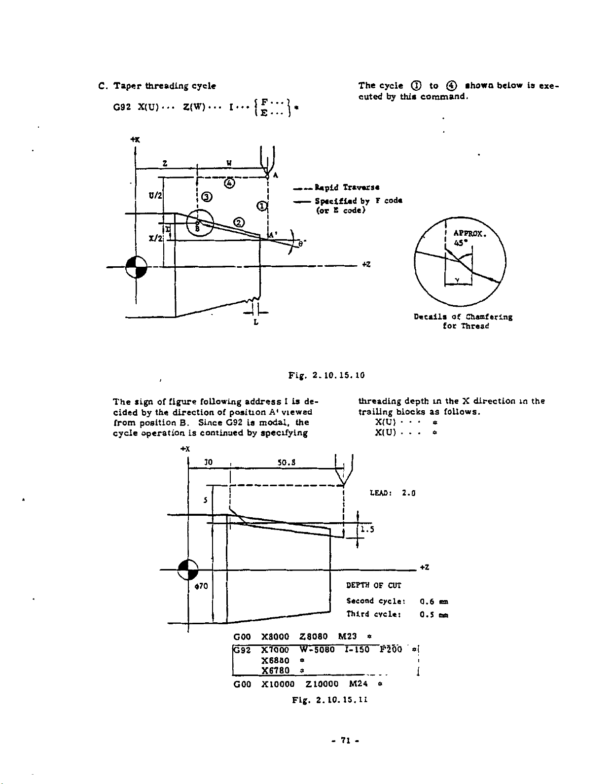
C.
Taper
G92
X(U)--.
+x
threading
z
D/2
cycle
Z(W)...
—
<
I©
(?)
to
command.
shown
below
is
exe¬
by
code
(T)
this
cycle
The
cuted
I
_
I
i
I
Rapid
—
Specified
—
—
(or
Traverse
code)
E
by
F
The
cided
from
cycle
X/2
sign
the
by
position
operation
of
I
figure
direction
Since
B.
is
+x
following
of
position
G92
continued
30
T~r
5
-1U
L
address
modal,
is
by
specifying
S3'
Fig.
de¬
1
is
viewed
A'
the
50.8
I
APPROX.
l
45*
+Z
calls
De
10
15.
10.
2.
in
X(U)
X(U)
depth
blocks
•
•
-
2.0
as
«
•
-
threading
trailing
i
LEAD:
Chamfering
of
for
Thread
theXdirection
follows.
the
in
v
GOO
G92
GOO
X8000
X7000
X6880
X6780
X10000
Z8080
W-5080
a
a
Z
Fig.
10000
10.
2.
-
M23
71
1.5
DEPTH
Second
Third
TTSO
M2
15.11
-
OF
CUT
cycle:
cycle:
a
F200
mm
0.6
mo
0.5
a
I
1
a
4
Page 80

Taper
D.
along
G92x(u)...
threading
the
angle
of
z(w)...
cycle
thread)
with
i...
U/2
the
thread
of
with
Rapid
—
Specified
—
(or
permits
in
the
sign.
a
traverse
code)
E
address
command
—
This
angle
the
figure
grammed
.
a
(
following
—
—
(Cutting
angle
K...
{£;;;)*
z
I
w
taper
by
threading
threading.
K
must
code
F
along
be
The
pro¬
I
&
I
X/2
Fig.
c
1
('
i
B
I
4V
J/
7P
2.10.15.12
4
!
4
rr
V,
f
K
A
CUT
OF
DEPTH
\
4ÿ
Kn
U
2.10.15.13
Fig.
72
-
-
Page 81
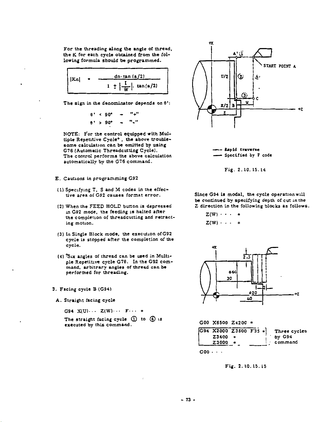
For
the
K
lowing
|Kn|
the
for
threading
each
formula
-
along
cycle
should
1
the
obtained
be
tan
dn-
±
|4-|-
of
angle
the
from
programmed.
(a/2)
(a/2)
t*n
thread,
fol¬
+x
U/2
<
N
START
POINT
*
A
V
i
The
NOTE:
tiple
some
G76
The
automatically
Cautions
E.
(1)
Specifying
tive
(2)
When
in
the
ing
(3)
In
cycle
cycle.
in
sign
For
Repetitive
calculation
(Automatic
control
in
area
the
mode,
G92
completion
motion.
Single
is
stopped
denominator
the
8’
<90*
90*
6
>
'
control
the
Cycle*
can
Threadcutting
performs
the
by
programming
and
T,
S
of
FEED
Block
G92
causes
HOLD
the
of
mode,
after
nÿii
equipped
,
the
omitted
be
above
the
command.
G76
G92
M
codes
format
button
feeding
threadcutting
is
the
completion
the
execution
depends
with
above
by
Cycle).
calculation
in
the
error.
is
depressed
halted
and
on
8’:
Mul¬
trouble¬
using
effec«-
after
retract¬
ofG92
of
the
«=Z
Since
be
continued
direction
Z
—
—
G94
Z(W)
Z(W)
Rapid
—
Specified
Fig.
is
in
•
8
r
2.
modal,
by
specifying
the
•
*
*
w
traverse
by
10.
IS.
the
following
F
code
14
cycle
depth
operation
blocks
will
cut
the
in
follows.
of
as
3.
(4)
Facing
A.
'ÿSix
angles
Repetitive
ple
mand,
performed
cycle
Straight
X(U)---
G94
straight
The
executed
arbitrary
for
B
facing
by
thread
of
cycle
threading.
(G94)
cycle
Z(W)-
facing
this
can
G76.
angles
••
cycle
command.
F-
of
be
In
••
(l)
used
the
thread
*
to
in
G92
can
(J)
Multi¬
com¬
be
is
-73-
GOO
G94
GOO
X6500
X2000
Z3400
Z3000
•
•
30
Fig.
460
Z4200
Z3800
o
«•
2.5
rf
I
Li
2|
I—
15.
—
*|
15
Three
by
cycles
G94
command
420
40
*
F35
10.
2.
Page 82

Taper
B.
G94X(U)--.
facing
cycle
Z(W).
.
.
K-••F--
+3C
(t)
The
cuted
taper
by
facing
this
cycle
command.
to
(4)
*
___
SI
*0
A-
—
tg
exe-
The
is
sign
decided
of
figure
by
the
O
following
direction
0/2
X/2
of
1
the
70
z
address
position
1
f
25
30
<§?
——Rapid
X
Spaciflad
+z
traverse
by
F
code
r
Fig.
A'
5
K
<t>2
10.
2.
I
I
I
!
0
15.
I
\
\
—
16
viewed
from
+z
position
B
C
Cautions
and
M,
S
effective
the
in
programming
functions
T
area
X7400
GOO
X2000
G94
Z2500
Z2000
•
G94
•
be
specified
GOO
cannot
of
G94.
Z3200
Z3000
*
«
Fig.
$
K-S29
F30
*
_
15.
10.
2.
in
74
-
17
G94
In
cycle
to
Single
is
©
stopped
.
Block
mode,
after
the
completion
the
execution
of
of
©
-
Page 83

Table
2.
10.
15
Canned
Cycles
Code
G90
G92
R
V
R
F
Z(W)...
F
Z(W)..-
Cycle
I--.
U
R
or
*.
I
R
WIDTH
IT
F*
(E)
F-
*
U/2
X
U/2
X
•
*
*
G90
Straight
X(U)*
F
•
*
z
Z(W}...
R
F
V
Cycle
Taper
F*
•
•
*
R
U/2
X
G90
X(U)-.-
F
z.
i
X(U)...
G92
45
i
z
-l,L
i
Z(W)..<
R
F
w
CHAMFERING
F-..
(E)
R
WIDTH
*
U/2
!
*5
:
1
:
I
G
£
z
92
X(U)-..
R
vF
—
u
CHAMFERINC
:
G94
G94
X(U).
U/2
•
Z(W)'
•
•
z
F
X
•
-
W
R
£1
R
F
F-
•
•
*
L
i
75
•
-
G94
X(U)-
U/2
Z(W)‘
-
-
z
K
F
X
*
w
R
F
•
*
K-
R
F*
~
-
Page 84

10.
2.
By
1.
the
face
four
Speed
runs
command.
G96
When
stant
effect.
16
using
spindle
speed
digits
Control
normally
and
power
Surface
CONSTANT
(G
96/
G96
G97
with
speed
constant.
command,
is
at
G97
are
supply
Speed
SURFACE
*
)
S
and
is
controlled
By
the
cancelled
the
speed
modal
is
turned
Control
SPEED
four
using
Constant
specified
codes
G
digits
G97
and
on,
Cancel)
CONTROL
command,
to
make
with
Surface
the
spindle
by
of
C
G97
sur¬
S
the
group.
(Con¬
is
in
and
Caution3
D.
(1)
Setting
In
be
meets
ting,
S
the
ting
Tool
The
is
coordinate
X
in
programming
the
of
mode,
G96
G50
set
by
the
with
theXcoordinate
diameter
point.
position
calculation
normally
made
coordinate
the
coordinate
so
that
zero
of
workpiece
offset
for
with
shown
the
in
X
pomes
G96
in
constant
the
below.
G96
system
system
spindle
axis.
at
mode
surface
current
to
the
center
By
be
current
should
this
equal
speed
value
line
set¬
to
cut¬
of
2.
A.
B
C.
Constant
G96
This
(m/min)
inch
tion
m
Ft/min.
Bythe
spindle
the
move
(diameter
nal
in
surface
the
mand.
For
spindle
ing
previous
refer
EXAMEIX.
G96
G50
Surface
S
command
(M03)
directly
is
speed
current
of
100
selected
the
to
speed
workpi-ce)
msec.
input
option,
command,
specified
of
each
speed
the
machine
be
can
gear
changed,
ratio
blocics
the
to
M41
-
S100
S
machine
...
*
-
M03
------
Speed
a
specifies
by
S
surface
the
keep
corresponding
position
can
whose
should
of
G96.
Example
for
*
Control
and
by
control
the
In
be
be
tool
low
(G96)
the
surface
digits.
four
Inch/Metric
is
speed
calculates
surface
tool
of
and
outputs
the
following
changed
ratio
gear
for
code
M
specified
For
the
builder's
code
of
M
gear
speed
'When
Selec¬
specified
speed
to
on
X
the
blocks,
S
by
of
chang¬
the
m
details,
manual.
the
com¬
the
axis
the
sig¬
X-coordinate
Commanded
*
Therefore,
offset
trol,
taken
•
The
•
each
Tool
used
at
offset
causes
The
for
coordinate
tool
position
for
value
too
incorrect
following
correct
by
offset
the
value
value
large
control.
system
method
offset
of
(POS*
Tool
+
value
surface
procedure
should
described
function
tool
wear.
C5C
hi
value
of
XCXÿJ
«o
position
tool
speed
should
should
Z(Z
in
be
)
x<Xjj
axis)
X
position
con¬
be
for
set
above.
be
•
'
ztz2)
*5
>
*
£Z
xi
Fig.
h
2z
2.
10.
16.
*2
1
This
mum
digits.
speed
Refer
If
the
ceeds
is
it
occurs
nates
command
spindle
The
surface
and
4.3.
to
calculated
maximum
the
clipped
commanding
by
G96
in
directly
speed
specified
1
Display
value
the
at
mode.
(rpm)
maximum
speed
of
spindle
specified
too
specifies
by
S
can
be
of
Command
spindle
speed
value.
small
the
and
four
spindle
displayed.
speed
specified,
coordi¬
X
maxi¬
Data.
ex¬
This
the
parameter
05
of
When
are
spindle
value
key
the
"1,"
formula
is
content
the
is
speed.
displayed
NOTE.
No.
following
tion
#
POS
POS
76
-
-
value
used
of
obtained
for
depressing
by
the
the
by
calcula¬
Page 85

X-coordinate
_
(The
ing
above
POS
-
keyj
T
ool
value
value(«POS
position
not
is
offset
displayed
MOTOR
SPEED
value#
value
in
X
by
axis)
depress¬
CR2,
this
In
(3)
can
start,
mand
The
i
ratio
case,
be
used.
cancel
in
G97
maximum
is
set
the
But,
and
(cancel)
spindle
with
tool
position
it
is
recommendable
change
mode.
speed
parameters.
the
offset
tool
for
offset
each
function
to
com¬
gear
the
For
machine
EXAMPLE
GOO
G50
S96
GO
1
G22
G01
G50
details
tool
X4000
M42
S1000
S1S0
Z0
X8000
W-1000
X12000
UlOOO
MOS
S2000
of
gear
builder's
Z500
-
M03
F15
Z-3000
=»
W-2000
*
#
«ÿ
IS'''
Parameter
ratio,
manual.
<ÿ
*
*
R2
SUL
No.
refer
000
86
SPINDLE
.
SPEED
to
Fig
No.
the
S*M
87
2.10.16.2
Example
Spindle
Constant
Sm
No
.
(4)
For
gearchange
2.
Constant
78
the
of
speed
surface
interface
gear
is
surface
(rpm)
signals,
command
Hi
clipped
speed
speed
such
ISO
refer
at
control
as
output
to
1000
m/nun.
the
rpm.
signals
and
APPENDIX
*
Release
of
spindle
speed
clipping
#
G97
POS
SS00
value
•
is
displayed
by
depressing
POS
-
key
77
-
Page 86

1—0
5
<M20
+x
20R
3.
"Cancel
”
2.10.17
G98
rate
feed
the
ter
per
of
S
G97
This
command
Speed
speed
digits
Control.
directly
following
FEED
(G98,
designates
millimeters
in
function
revolution.
constant
(M03)
FUNCTION
99)
G
the
feed
specifying
surface
#
cancels
The
specified
the
address
function
minute
per
speed
control
the
Constant
spindle
runs
m
rpm
by
S
DESIGNATION
specifying
designates
G99
feedrate
in
$
80
10
20
Fig.
(G97)
Surface
the
at
the
four
feed-
millime¬
2.10.
$40
iri
wv
$
16.3
•
G99
This
the
revolution.
Since
tive
G
F
cancelled
fore,
NOTE
However,
are
U
*
command
F
until
code
code
"
,
1
command
and
G98
erased
.
specified
when
new
F
When
when
G98
"
permits
in
G99
by
G98/G99
cor..mano
power
the
.
3
in
effect.
millimeters
are
the
in
the
should
is
turned
contents
the
control
modal,
command
previous
are
switched.
on.
of
parameter
(or
they
of
block
be
commanded
G99
to
execute
inchest)
are
new
is
effec¬
modal
will
There¬
in
effect
No
per
be
71
G98
This
the
minute.
command
command
F
permits
millimeters
m
the
control
(or
to
execute
inchest)
per
78
-
-
Page 87

TAPI
3.1
3.1.1
Both
EIA
punching
CODE
LIST
code
a
OF
paper
TAPE
and
tape.
ISO
CODE
code
are
3.
NC
available
TAPE
for
PUNCHING
EIA
ISO
Punching
shown
Before
(EIA
code
(ISO
code
patterns
in
Table
programming,
RS-244-A)
R840).
according
3.1.1.
•
select
to
the
these
code
codings
to
be
are
used.
Table
EIA
Code
2
1
1
I
°
o
tol
o
;
o
I
o
•
°
a
a
0
3
a
'
o
•
o
a
o
a
a
°
a
O
a
a
a
a
.
a
a
'
a
'
°
a
oO
o
.
a
a
:
o
a
.
;
a
I
o
O
a
1
a
1
o
<
o
o
|
o
o'Q'Q.d
I
t
I
'Qi
i
'
O
Qi
c
O'C
'
C
C'
C
C
C
C
C~
C
—
-
0
C
o
C
O'
;
i
,
I
'
Q
,
•
O'O
o
c
c
C
0-0
0
C
C
O'
O
O
o
O
C
o
O'
Q
OlO
I
IQ
i
o
O
o
o
o
O
o
0
JO
O
O
o
C
o
o
Blank
Tab
I
o
-
i
i
:o
Oal
I
:
n
I
I
I
i
.
!
;
O
i
•
I
O
'
‘
10
O O
o~o
O
o.
OOP
o o
o o
c
o
c
O
o
O
o
o
O
O
O
~
~
__
O
O-
1
O
•O'
_
|
.
I
_
—
;
I
l
I
6
1
O'O'OlQ
O
|0‘
;o<
I
iQio
O'O'OO'O'a'O
O
0
0-0
C
70.,
;
_
C,
9.9!:?
•
O
S-9L-
--
O
O
O
O
9
,
—
o
c
•
o o
o
O'
i
O!'O
OiO'Oio
r
-
I
'
'O'
I
,
0~
•
i
o
c1o
1
!
'
I
I
O'O
\
I
i
1
«
'O'O'
o
o
3.1.1
Character
0
2
3
5
6
7
s
I
1
!
I
T
;
I
f
I
I
BS
I
i
CR
SP
ER
UC
_
LC
l
I
/
M*rlt
All
Codes
Tape
i
a
I
I
1
4
o
_
oi
ouSiSotloffi
I
9i_[9!°l__0:9lobO
O'
i
0.0
°i9i_
OlO
O
0
-AOÿ_
o
"o'lQi
9i9
OIO
OIO
0.01
O'O'[O
OI
OI
Oi
Oi
O'
~T~TQI
_
Ot~T5j
O
-
»'
ISi-i
o.
oT
'O'
'O
o:
O'
o.
•0
IQ.
IQI
OiiO
lO,
;Oi
IQ'
i
1
O
A
B
c
0
z
F
G
M
t
j
X
L
M
N
0
P
0
B
$
T
u
V
w
X
Y
Z
NUL
HT
LF/NL
CR
%
(
)
_
£EL_lo:9'pL0
79
-
7
I
lOIOl
OiOl
oi
’O'O
1
6
i
:
—
I
1
OI
O'
o.
'O'
ro|
i
O
I
O
ISO
i
e
oi
o
—
-H
L
I
*~
'
.
1
I
i
r
:
IQI
9
i
jOl
‘O'
.O'
O
I
Oi
‘O.O'a;
lOlQ.a.
'
I
;
O
1
Q
Code
1
l
o
i
4
i
a
o"
‘o
,
-w
3
«
1
__
_
o
IO‘
i
o
<
O
rpTo.
a
o
-»
—
—
O'
2
5
o
“f
.9
J?,'9L_c'
i-
o
'O'O
o
•
.0.0
I
1
a
O
4.
O
O.
.
|°
i.
,
,oj_2_o
Qm
1
—
'
i
I
i
1
'O'
Om
O.
0
0
1
'
To-tto—
I
O
|Q
ipÿTo
O’
'
°
1
a
-
0
a
O'
l
o
Q
a
!
Lf_l
j
°
a
i
aÿo
a
~
.
a
a
Q
,
a
a
O'r
O
'a'
a
m_iOj
'°-t—
a
|
a
1
°
a
I
a
1
alO'Q
°
'QI
Q.
'Q.
i
!_J
—
|Q1
|
O'
O'O
i
t
.
r
'
O-
'
i
I
i
|
,
i
I
'00*0
J?
o‘o"
o
O'O
-0,0
'Q
i
'b
Qi
O
i
:o
_
|0
o
•>
—
—
o'
O
O
~Q
°
I
Q
O
i
O
i
1
'O
IO
•O
T
lo
O1
iQ
:
o
-
Page 88

3.1.2
Before
accomplish
tape,
code
tape
Parameters.
'
Where
the
control
read
to
code
tape
first
EOB
label
skipped.
the
With
the
control
In
tion.
according
shown
as-
0
1
E
I
A/l
operating
in
the
contents
will
the
tape
to
code
contents
does
this
to
below.
means
means
SO
/AUTO-SELECT
the
NC
system
the
changing
accordance
be
with
used
be
at
the
of
not
case,
the
contents
ELA
ISO
with
of
parameter
automatically
ELA
is
sensed
beginning
parameter
perform
the
tape
code.
code.
4.3.9
or
ISO
Auto-Select
code
of
parameter
with
operation
No.
adjusted
coding.
in
reading
of
the
No.
is
punched
of
Writing
80
are
so
The
the
with
tape
set
to
func¬
80
determined
No.
the
82
1,
as
If
INPUT
be
dicate
reader
tape
ERROR
illuminated,
alarm
NOTE-
ISO
code
82.
No.
3.2
PROGRAMMING
3.2.1
0,
The
sheet.
to
users,
and
an
PROCESS
programming
It
match
considering
convenience
example
reads
code
NC
tape
depending
is
recommended
final
of
the
on
lamp
and
the
"12
"
be
must
the
on
SHEET
is
performed
specifications
the
for
the
readily
rewriting.
process
NC
tape
the
operator's
universal
punched
contents
that
should
sheet.
of
unset
display
out
with
of
parameter
with
the
the
process
be
perceived
3
Fig
code
panel
will
ELA
process
made
form
2.1
will
ir
or
sheet
by
shows
N
LABEL
Fig.
[
X
P
3.2.1
EOR
*
•
U
|
0
Z
U
An
•
U
w
j
I
Example
I
K
I
i
I
I
l
of
the
K
“
«Ts“
D
!
Process
RE-
T-T
S
NARK
Sheet
80
•
-
Page 89

3.2.2
GENERAL
PROGRAM
FORM
A
part
following
program
form.
<
<
EIA
ISO
will
Code
|
Code
I
be
LABEL
LABEL
generally
~
ER
1
!
i
i
2
1
L
made
CR
f
!
i
LF/NL
I
u
in
These
BLOCK
These
STOP
the
NC
DATA
NC
DATA
called
are
character
are
called
character
Fig.
In
In
3.2.2
EOB
EOR
this
this
K30
.(or
M30
(or
or
or
manual.
M02)
M02)
of
END
manual.
REWIND
CR
LF/NL
ER
I
2
Any
LABEL
to
tape
function
EOB
code
address
nated
as
LABEL.
disregards
EOR
code
of
point
Where
label
the
between
code.
must
not
3.2.3
A
block
EOB
character
and
LF/NL
is
substituted
A
part
(End-of-P
When
M02
eration#
Is
reset,
matically.
machine,
manual.
can
be
classify
has
tape
storing
the
skip
In
parity
the
at
rewinding.
easily
data
readily
or
function
addition,
is
next
NC
skipped,
EOB
first
the
Therefore,
omitted.
be
PRECAUTION
ends
with
EOB
is
represented
ISO
in
them
for
program
ends
rogram)
or
M30
is
stopped.
or
rewinds
As
the
to
refer
written
the
tapes.
from
Therefore,
characters
the
also
available.
of
LABEL
data
tape
the
memory
code
EOR
code
IN
PROGRAMMING
(End-
code.
or
is
details
the
In
read
to
the
with
(End-of-Tape)
M30
commanded,
most
In
the
tape
are
machine
at
the
LABEL
modified
into
stores
and
at
the
Block)
of-
by
this
manual,
easily
block
cases,
(or
determined
tool
beginning
label
The
to
the
can
code
means
memory,
the
next
end
in
CR
this
Including
automatic
the
memory)
builder's
skip
the
first
undesig-
used
be
which
stop
the
with
data
the
EOR
of
tape
character.
code
EIA
mark
manual.
.
op¬
control
auto¬
by
of
M02
the
=*
NOTE
Slash
"/"
function.
the
at
head
quence
block,
the
of
the
optional
The
character
Function
ming,
Where
made,
is
even.
be
"SP"
character.
disregarded
The
SP,
UC,
significant
The
maximum
a
block
as
"Del.
"Automatic
ID
TAPE,
See
character
This
number).
Characters
others
but
the
tape
number
If
LC
is
64.
BS
MDI
7
2.
MISCELLANEOUS
means
code
block
If
function
skip
specified
should
(before
this
of
this
block
vertical
of
odd,
and
data
and
characters
should
it
characters
Del"
area,
allowable
disregarded
The
Tab"
operation"
or
MEM
be
must
is
is
switch
on
should
not.
parity
should
unnecessary.
if
number
not
are
means
mode
optional
the
surely
the
address
punched
disregarded
ON.
is
2.1.2
used
be
check
in
made
be
such
avoided
be
characters
included
operation
FUNCTIONS
block
punched
on
out
Address
for
program¬
(TV
a
block
even
"BS,
as
characters
of
in
N
by
from
of
the
even
and
check)
must
using
Tab,
such
them.
in
skip
out
se¬
way
if
the
in
81
-
-
Page 90

a.
Position
of
Optional
Block
Skip
2
5
N
1
*
)
DISREGARDED
Making
b.
*
(Odd
NO
8
5
0
*
N12
L
number
COO
/
1
Number
the
COO
20
The
C.
of
G
3
0
64
CHARACTERS
*
EFFECTIVE
of
Characters
X40000
CHARACTERS
Maximum
Characters
X-
•
•
tape
Z-
causes
(Even
Allowable
OR
6
N
2
001
1
/
l
I
even
20000
Z
Number)
a
parity
Number
Block
vertical
in
BELOW/BLOCK
SP
Z-.
for
TV
*
Check
*
-
error.)
.
M
-
.
•
F
*
3.3
NC
TAPE
3.3.1
PAPER
Eight-channel
with
ing
mensions
0.
It
black
If
tape
3.3.2
NC
er
of
JIS#-6243
are
108
mm
is
recommended
or
gray,
the
tape
reader
PUNCHING
must
tape
for
EIA
process
paper
25.4
(0.0042
with
may
be
code
sheet.
TAPE
is
inch)
but
high
misread
OF
punched
or
for
tape
used
±0.08
mm
thickness.
that
the
that
not
transparency
NC
out
code
ISO
computers
as
color
of
it.
TAPE
with
according
standard.
inch)
(1
of
high
transparency
is
the
the
used,
tape
comply¬
The
width
tape
to
Fig
di¬
and
is
the
punch¬
contents
3.2.3
When
endofthe
for
ed
is
wound
holes
3.3.3
NC
func
Machine
M
•
Dry
•
Single
#
Japanese
punching
the
on
part
CHECKING
can
tape
tion.
function
run
block
.
tape,
feeding.
tape
the
be
will
be
checked
lock
lock"
operation
Industrial
:e
tape,
provide
reel'1’
70
OF
at
the
Where
of
tape
in
cm
NC
TAPE
by
Standard
the
feed
reader,
length.
using
beginning
holes
the
punched
following
the
the
part
and
feed
the
need¬
tape
82
-
-
Page 91

3.4
NC
3.4.1
To
splice
thickness)
TAP*
TAPE
NC
with
HANOUNG
FOR
SPLICING
tapes,
stick
sprocket
a
joining
holes,
NC
TAPE
tape
or
fully
(0.
perfo-
08
mm
rated
joining
NC
tape.
that
sure
joining
do
and
flexibility.
part
not
tape
Before
the
sprocket
of
use
using
tapes
the
on
the
the
holes
should
rigid
side
one
spliced
are
not
adhesive
of
NC
in
be
extremely
agent
the
spliced
tape,
position.
make
The
thick,
without
3.4.2
life
For
handling
NC
KEEPING
expectancy
recommended.
is
O5O
7
IA
OF
Cii
L
PE
NC
of
COOOOOOOCQ
00000007000
ooeooooooco
5000000000
oca
oo
hoc
30000
OO
coooocoo
oo
ooooooo
APPROX.
W
30
TAPE
NC
tape,
ooooo
CC
OO
_
the
o
1
.
?
v
.
Fig.
following
9
3.4.1
JOINING
Splicing
TAPE
of
When
.
not
Do
Properly
reading
Example
'NBC
8-CHANNEL
FULLY
NC
Tape
keeping
handle
kept
and
SPLICE
PERFORATED
NC
the
tapes
rewinding.
TAPE
tape,
tape
will
avoid
with
permit
moisture
oil-stained
300
times
and
gloves.
of
oil.
83
-
-
Page 92

POWER
ON
«
co
OFF
tAOV
•
o o
i*ruT
1IKD«
o
14«li
luMU
o
*C
ItllllT
AlAAM
o
o
AOORESS
/
T
FUNCTION
(0BQBHB1
BBB
-J
»-
A
AM
L“»TAlUi*J
u
0
J
L
A
COM
FES
*
=rTD
AODRESS
x
l
c
M
P
R
Q
03
At
cool
NUUK
A
NUM6ER
[fflfS
Dll
gs
ra
000
B0S
D
B
START
At
I
t
RESET
WA
o
Fig.
*1.1,0
t
Standard
/
NC
Operator's
Panel
Page 93

PUSHBUTTONS,
4.1
4.1.1
•
POWER
To
turn
first
to
again
recover
to
POWER
ON
on
turn
to
turn
servo
KITS,
ON/OFF
pushbutton
the
control:
on
control
on
servo
power
4.
AND
LAMPS
PUSHBUTTONS
Depress
power
power.
after
and
Push
emergency
NC
OPERATOR
the
button
depress
the
button
stop.
S
PANEL
•
BUFFER
is
It
the
has
START
eration#,
it
and
storing
on
buffer
been
the
lamp
when
dataInthe
register.
evacuated
or
RESET
a
block
goes
lamp
conditions.
by
button.
of
data
on
It
and
next
block
goes
off
depressing
Tn
the
is
read
off
according
are
when
the
automatic
in
advance,
held
the
buffer
CYCLE
to
buffer
in
op¬
POWER
•
Depress
power.
1.2
4.
•
READY
It
lights
with
servo
cannot
ically.
LABEL
•
It
when
has
that
tape
tered.
In
Indicates
display
formation
OFF
to
it
POWCN
©
orr
©
INDICATING
lamp
when
up
units.
be
SKIP
when
power
It
MEM
is
normally
operated
reset.
tape
goes
that
related
but
power
on
is
been
makes
information
the
pushbutton
remove
Fig.
LAMPS
the
While
lamp
LabelSkip
the
been
has
The
setting
until
off
or
EDT
memory
to
not
control
supplied
it
either
turned
Label
when
mode,
to
only
MDI
servo
o
O
4.1.1
remains
easy
the
EOB
or
power
o
o
•arrtPv
O
O
EEL
is
to
manually
function
on
Skip
by
first
has
the
illuminated
is
tape
or
tape
operation.
and
P
r?
c
ru*
ready
the
off.
or
the
is
ignoring
EOB
been
rewound.
memory
control
A
to
control
the
automat¬
or
effective
is
control
function
the
is
encoun¬
read.
operate
control
all
lamp
This
in¬
and
•
INPUT
It
goes
information.
tion
block
prevented.
on
are
•
Tape
Use
•
Mispunched
•
•
Dirty
•
Misreading
Destroyed
Set
the
the
detailed
The
reset.
#
Automatic
tion
manual
JOG,
ERROR
on
when
is
suspended
has
been
as
follows:
format
of
wrong
tape
FUNCTION
lamp
goes
in
auto-mode
operation,
or
RAPID
POWER
ON
OFF
lamp
an
At
executed,
Possible
error
characters
information
of
paper
memory
information
off
operation
4
Fig.
error
time,
that
immediately
causes
tape
contents
select
when
the
is
(TAPE.
as
the
mode
in
©
(MON
o
1.2
is
detected
automatic
and
on
reader
key
of
error
control
defined
operation
this
after
Cycle
for
paper
to
MDl,
manual
lumi
iw
©
o
NC
A
NATTC
LAMM
o
**
o
IEEIDF.
in
input
opera¬
the
current
Start
lamp
the
tape
to
ALM
alarm
in
as
been
has
opera¬
the
MEM)
or
inHANDLE,
AOORC
T
FUNCTlOf
then
is
to
go
obtain
code.
and
N
M
85
-
-
Page 94

•
NC
ALARM
LS
It
mentioned
trol.
it
stops
depending
prevented.
The
reset
cording
Display.
•
BATTERY
is
It
level.
new
a
tenance
is
used
set
values
on
when
If
the
immediately
lamp
after
to
on
when
Then
one
personnel
for
lamp
an
above
control
on
the
off
goes
taking
the
error
lamp
battery
the
within
protection
and
tape
error
has
is
error.
when
the
.
battery
a
month.
for
memory
other
been
in
automatic
at
or
Then
the
correct
See
voltage
must
battery
of
parameters,
than
detected
end
the
Cycle
control
measures
4.3.
12
below
is
be
Contact
change.
at
power
input
in
the
operation,
of
a
block,
Start
has
AlarmCode
a
replaced
the
Battery
tool
OFF
error
been
ac¬
safe
main¬
con¬
is
with
off¬
4.1.4
The
or
write
•
0
Each
indicator
key
Indicator
until
•
0
Each
indicator
is
held
cator
the
Pushing
cator
ADDRESS
keys
select
command
Key
depression
held
is
the
Key
depression
in
will
is
key
the
back
go
to
the
in
will
is
key
to
the
for
more
continue
released.
both
to
SELECT
an
address
data.
the
of
right
for
more
continue
released.
of
the
left
by
than
to
ADDRESS
"X.
"
KEYS
key
by
than
to
key
one
move
one
0
AND
character
moves
address.
0
5
move
automatically
moves
address.
5
second,
automatically
keys
makes
DISPLAY
to
the
address
If
second,
the
address
If
the
the
display
the
the
the
key
indi¬
until
indi¬
4.1.3
The
key
eration
makes
•
ALM
or
I/O
•
PRM
parameters.
operation
•
COM
write
tion.
•
POS
tool
•
OFS
offset
FUNCTION
selects
the
of
it
(Alarm)
(Parameter)
(Command)
a
(Position)
position.
(Offset)
display
up.
light
signal.
time
command
key
value.
mniHiag
SELECT
of
one
key
To
key*
With
parameter
is
displayed.
key
value
key:
To
M
T
FUNCTION
five
and
To
To
display
a
KEYS
functions
MDI
display
To
display
display
for
automatic
display
poo
Pushing
an
No.
the
or
write
*
for
the
alarm
or
write
at
set
manually
or
opera¬
current
tool
i
AOORESS
EH
a
code
key
00,
op¬
AOORESS
/
T
FUNCTION
jnEHEa
4.1.5
The
number
or
•
Each
al
than
increase
NUMBER
NUMBER
writing
Key
0
depression
display
0
or
5
X
l
I
s
R
M
P
|
Q
SETTING
keys
a
parameter
tool
offset
at
right
by
l.
second,
automatically
(
u
Fig.
of
If
D
are
the
w
|
A
L
AOORESS
EB
4.1.4
KEYS
used
number
value
the
the
number
key
key
until
£
AND
to
set
or
parameter.
increases
held
is
will
the
s
%
ran
DISPLAY
a
when
continue
key
I
/
c
NUM0ER
tool
displaying
the
for
in
released.
is
j
offset
digit¬
more
to
Fig.
1.3
4.
86
-
-
Page 95

•
Each
al
than
increase
By
set
Key
S
depression
display
0.
pushing
back
J
U»—
f
F
K
DRESS
3B
left
at
by
10.
5
second,
automatically
the
both
to
"00.
"
W
DiAM
WHKR
£
S
!
I
*
NUMBER
EE
of
If
the
NUMBER
-j
COM
J
L
the
the
number
key
increases
key
is
will
until
key
keys,
BEE
7
IQ]
4
m
1
IS
I
CAM
I
II
held
is
r
L
[
£-
the
for
in
continue
released.
NUMBER
digit¬
more
to
is
"
*
fore,
block
11
Key
and
advanced.
,0*1
is
to
+
"
"
7
[olio]
4
lolls!
1
(OltOl
long
search
key
Fig.
data
1.9
of
the
START
RESET
one
block
data
be¬
of
one
the
is
to
search
\
4.
4.1.6
Twelve
(cancel)
command
data
ter
the
input
4.1.7
Depress
the
buffer
4.1.8
Depress
contents.
Search.
DATA
keys
are
value,
is
built
value,
(WRITE)
WR
to
it
register,
(ADDRESS
AS
to
it
For
K!-VS
of
0
through
provided
tool
on
use
store
start
details,
Fig.
4.1.5
for
offset
the
universal
the
CAN
KEY
the
input
SEARCH)
searching
see
9,
-
manual
value,
key.
data
4.3.
(minus),
display.
KEY
tape
14
data
input.
and
parame¬
displayed
or
memory
Address
and
To
CAN
Any
clear
into
1.
4.
These
data
•
ERS
It
the
•
INS
It
press
that
After
board,
data
goes
•
ALT
It
•
EOB
10
ERS
(ALTER)
keys
effective
and
(erase)
is
to
deleteablock
EDT
(insert)
to
store
is
the
the
a
block
depress
into
off.
(alter)
is
to
modify
(end
(ERASE)
are
key
mode.
key
key
operator
the
key
block)
of
y
AND
for
storing
only
block
a
first,
may
is
built
the
memory.
address
y
EOB
in
of
and
through
key
key
INS
the
of
data
start
again
Then
data
(INSERT)
(END
editing
and
EDT
data
in
into
it
lights
MDI
the
to
the
m
OF
mode.
the
memory.
up
operation.
DATA
store
indicating
a
block.
y
ALT
BLOCK)
block
a
memory
indicating
key¬
the
KEYS
of
m
De¬
built
lamp
4.1.9
Sequential
between
or
tape
SEQUENTIAL
search
WR
and
AS
contents
in
SEARCH
keys
keys
the
i
"
are
MEM
KEYS
and
"
to
and
0
"t"
search
EDT
AND
located
memory
modes.
buff¬
the
EDT
in
mode
store
into
a
block
of
memory
data
in
written
the
to
is
0
It
er
register
87
-
-
Page 96

BEB
HiH
START
11
1.
4.
1
KEY
IF
It>
Fig.
START
o
4.
1.10
Memory
•
and
parameter
NOTE:
button
reset
manual.
1.13
4.
display
The
number
offset
shown
digits.
the
or
displayed
contents
Depressing
is
UNIVERSAL
unit
data
the
is
On-line
result
of
8
in
digits.
such
data
the
defined
DISPLAY
shows
and
parameter
consisting
diagnostics
a
part
as
RESET
Reset
as
all
the
of
off-line
tool
data
number.
a
of
such
offset
key
or
operation
other
sign
as
I/O
diagnostics
values
the
than
Usually
and
signals
remote
in
this
seven
tool
are
used
is
It
1.
mode,
12
key
from
RESET
storing
MDI
eration.
builder's
4.
The
Operations
button
reset
are-
•
•
•
•
•
•
•
•
•
The
pressing
button).
•
•
•
•
command
Move
Buffer
Alarm
offset
Tool
Miscellaneous
Skip
Label
Memory
Sequence
signal
RST
following
Current
Modal
commands
F
S
4-digit
2-digit
S
to
start
tape*
it
For
manual.
resets
executed
connected
register
code
cancel
function
pointer
number
RESET
the
position
G-codes
commands
commands
tape
in
be
may
details,
KEY
control.
the
by
cancel
clear
release
function
rewind
reset
transmission
data
remain
key
value
(except
punching
the
used
refer
RESET
to
the
if
cancel
ON
(or
of
G-codes
are
mode.
EDT
for
Cycle
to
the
key
ERS
input
cause
the
to
unchanged
remote
X-,
affected
and
machine
{or
eliminated
machine
and
of
program
In
Start
remote
terminal)
alter
reset
X-axis
group)
B
the
op¬
tool
de¬
ADORESS
4.1.14
These
reader.
•
TAPE
It
the
(forward)
the
H
/
T
M
switches
is
control
tape,
TAPE
FEED
to
G
ft
feed
o
I
M
causes
set
u
Z
0
FEED
are
switch
and
at
standby.
the
j
0
rewind
w
F.g.
l.
*
AND
mounted
the
tape
switch
K
t
4.1.13
SYSTEM
the
Setting
to
to
R
S
*
NO.
above
tape
feed.
(reverse).
AUM
coot
NUM*C«
in
SWITCHES
the
manually
switch
the
To
-
tape
rewind
with
to
F
88
-
-
Page 97

4.2
4.2.1
POWER
TURNING
ON/OH
ON
OPERATION
POWER
o
o
•
SYSTEM
Set
the
Functions
Setting
"0"
SYSTEM—
For
usual
prevented.
"1"
PARAMETER—
To
write
Start
is
when
parameters
"2"
CHECK—
collate
To
system
"3”
LOAD—
store
To
"4"
TEST
Usual
memory
the
Position
turn
"5"
TEST
Writing
the
memory
check
o
i
niMRi
i
coat
1
LOU
«
TOT
a
m
O
NO
switch
to
at.
operation.
parameters.
prevented.
the
tape.
maintenance
(0)—
operation
(1)—
parameters
omitted.
are
firm'll
0
e
(0)
113111
m
o
I
switch
at
its
system
is
contents
are
contents
Fig.
"0"
setting
Set
have
permitted.
omitted.
I
4.
during
Writing
program
tape
and
is
and
TAPE
FEED
o
1.14
usual
are
as
At
this
the
switch
been
written.
data
checking
effective.
Zero
o
R
O
o
o
operation.
follows.
parameters
position.
back
stored
into
the
Diagnosing
of
Diagnosing
Return
Cycle
to
with
control.
Zero
position
is
"0"
the
of
Re¬
Before
ferring
Depress
1.
trol
about
ready
in
Depress
2.
on
nal
is
3.
When
the
CHINE
control,
machine
POWER
Fig.
turning
to
power.
two
alarm
servo
is
ready.
the
power
ON
APPROX.
2
SECONDS
ALARM
CODE
4.2.1
the
the
seconds.
for
turning
code
the
power.
given
NRD
of
READY)
the
is
on
power,
machine
POWER
The
"31."
POWER
which
(NC
the
signal
READY
ready
POWER
ON
i
i
l
"31"
Sequence
tool
ON
initial
Then
on
power,
ON
The
NRD
indicates
READY)
machine
lamp
to
operate.
l
l
i
1
i
1
I
I
t
of
check
builder's
button
timer
the
button
and
is
given
will
CONTROL
NRD
SERVO
SRD
MACHINE
MRD
READY
3LANK
Turning
the
will
servo
which
(NC
that
signal
the
(NC
(NC
(MACHINE
machine
manual.
to
turn
can
again
READY)
the
MRD
back
be
lit.
POWER
READY)
POWER
READY)
POWER
LAMP
on
on
be
reset
unit
is
be
shown
to
turn
sig¬
control
on
turns
(MA¬
the
to
The
READY)
Operation
re¬
con¬
in
NC
of
89
-
-
Page 98

4.2.2
Depressing
power
TURNING
and
taneously.
take
tion,
1.
Depress
servo
off
which
power,
2.
Depress
control
CONTROL
CONTROL
SERVO
POWER
(NC
NRD
the
control
However,
the
the
power.
results
too.
the
power.
POWER
READY
READY)
OFF
POWER
POWER
following
OFF
power
for
procedure
EMERGENCY
NRD
in
turning
POWER
EMERGENCY
STOP
I
l
I
i
to
stabler
signal
OFF
button
be
off
turned
STOP
is
the
button
POWER
causes
off
system
.
button
interrupted,
machine
to
cut
OFT
servo
simul¬
opera¬
to
off
cut
YASNAC
2000G
4.3
EON
EOF
COM
Fig.
DISPLAY
i
4.2.3
Connections
ON
/OFF
AND
WRITING
MACH
o
do
Buttons
INE
—
of
OF
REMOTE
OFF
REMOTE
ON
Remote
COMMAND
POWER
BUTTON
POWER
BUTTON
Power
DATA
MACHINE
MRD
READY
ALARM
CODE
Fig.
-1.2.3
Connect
COM
then
remote
POWER
(MACHINE
LAMP
4
2.2
REMOTE
power
terminals
READY)
BLANK
Sequence
TURNING
on/off
of
turning
aurrc*
o
•Am**
o
of
buttons
the
on/off
\
"33"
Turning
ON/OFF
control
operation
AOORESS
N
M
T
FUNCTION
to
as
G
RIP
EON,
x
o
Operation
Off
BUTTONS
EOF,
shown
can
_
below.
be
/
I
w
u
l
A
0
0
and
made.
UNIVERSAL
j
J
J
L
*-»*TATl»—
K
<
L
AOORESS
IBB
u
1.
J
f
4.3.1
Command
the
Depress
1.
Select
2.
displayed
DISPLAY
C
J
£
s
=
-
EE3
DISPLAY
following
key
Then
ed.
regist-.r
ation.
The
c'-.rdinate
with
C
~!
U
COOK
MUM
If
n
U
NUMBER
data
the
address
an
command
The
when
,
ufiset
t
A
I
R
i
I
OF
can
procedure.
COM
data
data
shows
the
the
the
is
vt.ue.
TT\
I
i
5HE
COMMAND
be
displayed
key,
character
already
the
control
control
contents
values
fZtl
a
j
9J
6
5
1
SB
DATA
in
and
it
with
entered
contents
in
is
stopped
the
of
displayed
any
lights
automatic
at
buffer
mode
up
ADDRESS
the
is
of
the
block
are
using
display
active
oper¬
end,
register.
modified
Fig.
1.1
4.3
90
-
-
Page 99

Use
tate
3.
To
lected
All
displayed
releasing
obtained
versal
To
4.
G-codes
and
C,
Refer
is
All
ting
G.
following
the
the
display
display
the
display
non-modal.
and
to
a
G-code
the
NUMBER
See
all
block
address
while
the
by
display.
allG-codes
are
groups
D
Table
current
Fig.
steps
operation.
address
characters
the
COM
2
step
classified
Modal
and
2
10.
.
of
A
group
G-codes
at
"99"
4.3.
following
COM
key,
appears
non-modal,
1.2.
and
1.2.
characters
the
in
Is
key
the
command
again
into
two
are
G-codes
Usually
or
non-modal
are
displayed
selecting
step
held
types,
to
2
the
in
block
in.
on
the
of
of
group.
*
displayed
type.
address
facili¬
se¬
can
data
uni¬
modal
A,
by
set¬
By
B,
be
Fig.
4.3.2
Usually
codes
”99"
3
C
4.3.
WRITING
displayed
are
and
imi'r"SAL
n
u
1.3
displayed
selecting
n
n
u.
u
MAX.
SPEED
n50
Example
COMMAND
is
address
DISPLAY
SPINDLE
(RPM)
.
S-
•
surface
by
setting
i
c
i
J
I-
*
All
of
DATA
speed.
NUMBER
S.
n
u
CONSTANT
SURFACE
(H/MIN)
S-codes
MDI
BY
Both
SPEED
Display
S-
at
UNIVERSAL
Q
1
Fig.
To
5.
S-code
constant
spindle
o
o
/
I.
—
n
D
CROU”
1.2
4.3.
display
to
is
surface
speed
AOORESS
/
T
FUNCTION
nEBB
DISPLAY
u
c
1
Q
—
*“C
CROUP
Example
two
types
specify
(rpm--set
N
X
G
O
p
M
n
H
U.
—
B
*—
of
surface
speed
_
u
z
o
2.
n
n
u
U
c:
CROUP
of
All
S-codes
control
by
UNIVERSAL
/
~i
/
L
w
A
L
aa
CROUP
OR
NON
MODAL
G-code
speed(m/min)
and
S
G50
/_/
3
J
/.
F
C
K
A00RE5S
Display
maximum
•••
DISPLAY
"
C
C
U
J
fc-
MiM
$
I
i
*
NUMBER
BE
a
block
of
MDI
end.
data
HOLD
the
data
mode
Writing
remains
operation
pushbutton.
MODE
the
COM
address
the
command
on
the
El
when
select
universal
«t
Command
the
in
block
if
the
automatic
FEED
Set
1.
2.
Depress
3.
Select
key
Modal
played
for
*).
I
W
the
operation
the
in
after
or
switch
key
character
already
data
START
can
active
and
be
control
cannot
a
temporary
it
display.
written
is
register
the
to
will
with
executed
manually
stopped
allowed
be
during
stop
MDI
mode
light
up
ADDRESS
is
at
by
dis¬
3
c
Iffl
CAM
SB
TJ
*
RESET
o
Fig.
4.3.2
91
-
-
Page 100

new
Key
board.
The
in
display
4.
the
flickering
the
/
rect
key
5.
Depress
‘
The
ister
values
offset
6.
Repeat
been
7.
Depress
the
and
data
asanew
displayed
value.
steps
written.
input
data
key
NOTES.
•
Depressing
eration
written.
G-codes
(G41
{G70
tion.
versal
register
•
When
the
setting
Ley
mooul
See
to
to
New
writing
written
G-codes
type
4.3.1
by
for
G44)
G76)
display,
by
the
data
shows
the
last
just
m
the
WR
the
keyed
just
command
3
through
the
CYCLE
commands
the
RESET
deletes
MDI
Nose
Tip
and
cannot
G-code
but
WR
the
G-codes
value
number
of
not
are
Display
through
the
significant
keyed
correct
key.
in
are
START
are
Multiple
be
can
never
key.
on
the
at
"99"
other
usually
of
Command
data
in,
enters
data.
modified
until
5
executed.
key
all
the
Radius
Repetitive
changed
be
displayed
entered
of
BtoD
universal
than
the
DATA
as
is
it
digit.
depress
data.
the
The
with
a
block
pushbutton,
during
writing
data
Compensation
MDI
by
the
groups,
display
the
with
A
group
displayed.
Data.
key¬
entered,
To
the
buffer
coordinate
tool
the
has
already
Cycles
opera¬
the
on
buffer
NUMBER
and
non-
cor¬
CAN
reg¬
and
op¬
uni¬
check
by
Also
maximum
play
NUMBER
All
•
block
by
tion.
4.3.3
The
current
played
cedure
Depress
1.
2.
Set
keys.
Then
displayed
Either
ordinate
setting.
Where
•
Displayed
on
•
Universal
ment
ation.
•
Tne
switch
check
by
setting
key.
address
the
can
be
depressing
See
4.3.
CURRENT
any
at
as
is
POS
the
ADDRESS
current
total
amount
value
parameter
current
the
current
display
the
of
cannot
It
display
set
is
S-code
spindle
the
displayed
the
1
POSITION
position
time
follows.
key,
position
on
the
can
position
tool
is
updated
to
(GSO
speed
number
characters
on
COM
Display
X-,
of
all
in
modes.
and
to
XorZ
universal
of
movement
be
displayed
No.
72
position
shows
manual
by
be
reset
MACHINE
*
S
•
on
at
already
the
key
of
DISPLAY
or
it
lights
of
the
1
"0"
is
display
total
and
by
/en
LOCK
•
•
*)
universal
"99"
specifying
with
the
written
address
during
MDI
Command
Z-axis
Operating
up.
using
ADDRESS
selected
display
or
absolute
by
parameter
same
the
unit".
amount
automatic
G50.
the
u
LOCK
position.
display
Data.
can
axis
as
of
dis¬
the
in
opera¬
be
dis¬
pro¬
is
co¬
that
move¬
oper-
MODE
a
O
«ATT|*t
O
AOORESS
N|G
/
Mj
r
FUNCTION
X
o
R
P
BBaBBa
_
2
Q
/
l
W
U
A
0
UNIVERSAL
J
J
J
L
K
L
AOORESS
EB
u
1.
e
Fig.
DISPLAY
c
U
J
s
x
NUMBER
0X0
4.3.3
92
-
<:
I
-
ACT
1
3
_LJ
n
B
At
4
\
«a
~i
I
4
coot
/
j
L
EE
PS
ES
2
i
J
30
 Loading...