

Page 1
YASKAWA AC Drive A1000 Option
120 Vac Digital Input
Installation Manual
Type: DI-101
To properly use the product, read this manual thoroughly and retain
for easy reference, inspection, and maintenance. Ensure the end
user receives this manual.
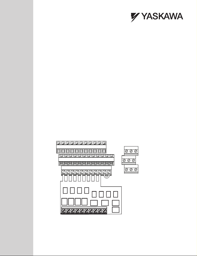
E(G)
HC H1 H2 DM+ DM- IG R+ R- S+ S-
M3 M6 M4
V+ AC V- A1 A2 A3 FM AM AC MP RP AC
S1 S2 S3 S4 S5 S6 S7 S8 SN
S1 S2 S3 S4 S5 S6 S7 S8 SN
MANUAL NO. TOEP YEAOPT 07
SC SP
M1 M2 M5
MA MB MC
Page 2

Copyright © 2011 YASKAWA ELECTRIC CORPORATION
All rights reserved. No part of this publication may be reproduced, stored in a retrieval system, or
transmitted, in any form or by any means, mechanical, electronic, photocopying, recording, or otherwise,
without the prior written permission of Yaskawa. No patent liability is assumed with respect to the use of the
information contained herein. Moreover, because Yaskawa is constantly striving to improve its high-quality
products, the information contained in this manual is subject to change without notice. Every precaution has
been taken in the preparation of this manual. Yaskawa assumes no responsibility for errors or omissions.
Neither is any liability assumed for damages resulting from the use of the information contained in this
publication.
2 YAS KA WA TOEP YEAOPT 07 A1000 Option DI-101 120 Vac Interface Installation Manual
Page 3

Table of Contents
1 PREFACE AND SAFETY . . . . . . . . . . . . . . . . . . . . . . . . . . . .4
2 PRODUCT OVERVIEW . . . . . . . . . . . . . . . . . . . . . . . . . . . . . .7
3 RECEIVING . . . . . . . . . . . . . . . . . . . . . . . . . . . . . . . . . . . . . . .8
4 OPTION COMPONENTS. . . . . . . . . . . . . . . . . . . . . . . . . . . . . 9
5 INSTALLATION PROCEDURE . . . . . . . . . . . . . . . . . . . . . . . 10
6 TROUBLESHOOTING. . . . . . . . . . . . . . . . . . . . . . . . . . . . . .21
7 SPECIFICATIONS . . . . . . . . . . . . . . . . . . . . . . . . . . . . . . . . .22
YAS KA WA TOEP YEAOPT 07 A1000 Option DI-101 120 Vac Interface Installation Manual 3
Page 4
1 Preface and Safety
1 Preface and Safety
Yaskawa manufactures products used as components in a wide variety of industrial systems
and equipment. The selection and application of Yaskawa products remain the responsibility
of the equipment manufacturer or end user. Yaskawa accepts no responsibility for the way its
products are incorporated into the final system design. Under no circumstances should any
Yaskawa product be incorporated into any product or design as the exclusive or sole safety
control. Without exception, all controls should be designed to detect faults dynamically and
fail safely under all circumstances. All systems or equipment designed to incorporate a
product manufactured by Yaskawa must be supplied to the end user with appropriate
warnings and instructions as to the safe use and operation of that part. Any warnings
provided by Yaskawa must be promptly provided to the end user. Yaskawa offers an express
warranty only as to the quality of its products in conforming to standards and specifications
published in the Yaskawa manual. NO OTHER WARRANTY, EXPRESS OR IMPLIED, IS
OFFERED. Yaskawa assumes no liability for any personal injury, property damage, losses,
or claims arising from misapplication of its products.
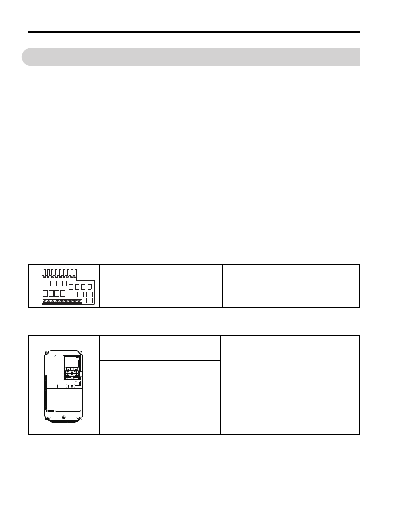
◆ Applicable Documentation
The following manuals are available for the option and drive:
Option
Yaskawa AC Drive -A1000 Option
DI-101 120 Vac Interface
Installation Manual
Manual No: TOEP YEAOPT 07
Read this manual first.
The installation manual is packaged with the
DI-101 120 Vac Interface Option and contains
installation procedures and precautions.
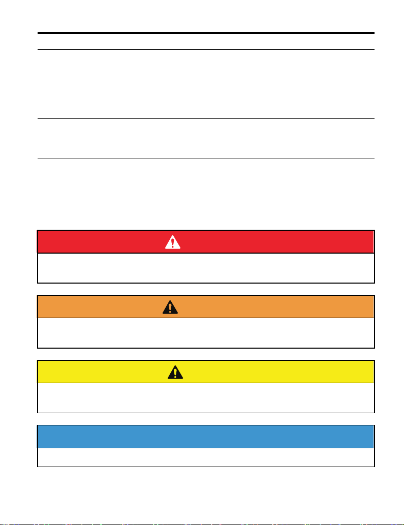
Yaskawa Drive
Yaskawa AC Drive
A1000-Series
Quick Start Guide
Yaskawa AC Drive
A1000-Series
Technical Manual
4 YASKAWA TOEP YEAOPT 07 A1000 Option DI-101 120 Vac Interface Installation Manual
The drive manuals cover basic installation,
wiring, operation procedures, functions,
troubleshooting, and maintenance information.
The manuals also include important
information about parameter settings and drive
tuning. Access these sites to obtain Yaskawa
instruction manuals:
U.S.: http://www.yaskawa.com
Europe: http://www.yaskawa.eu.com
Japan: http://www.e-mechatronics.com
For questions, contact your local Yaskawa sales
office or the nearest Yaskawa representative.
Page 5
1 Preface and Safety
DANGER
W ARNING
CAUTION
NOTICE
◆ Terms
Note: Indicates supplemental information that is not related to safety messages.
Drive: Yaskawa AC Drive A1000-Series
Option: Yaskawa AC Drive A1000-Series Option Digital Input DI-101
◆ Registered Trademarks
Trademarks are the property of their respective owners.
◆ Supplemental Safety Information
Read and understand this manual before installing, operating, or servicing this option. Install
the option according to this manual and local codes.
The following conventions indicate safety messages in this manual. Failure to heed these
messages could cause fatal injury or damage products and related equipment and systems.
Indicates a hazardous situation, which, if not avoided, will result in death or serious
injury.
Indicates a hazardous situation, which, if not avoided, could result in death or
serious injury.
Indicates a hazardous situation, which, if not avoided, could result in minor or
moderate injury.
Indicates an equipment damage message.
YAS KA WA TOEP YEAOPT 07 A1000 Option DI-101 120 Vac Interface Installation Manual 5
Page 6
1 Preface and Safety
DANGER
NOTICE
■ General Safety
General Precautions
• The diagrams in this book may include options and drives without covers or safety shields to
illustrate details. Be sure to reinstall covers or shields before operating any devices. Use the option
according to the instructions described in this manual.
• Any illustrations, photographs, or examples used in this manual are provided as examples only and
may not apply to all products to which this manual is applicable.
• The products and specifications described in this manual or the content and presentation of the
manual may be changed without notice to improve the product and/or the manual.
• When ordering new copies of the manual, contact a Yaskawa representative or the nearest Yaskawa
sales office and provide the manual number shown on the front cover.
Heed the safety messages in this manual.
Failure to comply will result in death or serious injury.
The operating company is responsible for any injuries or equipment damage resulting
from failure to heed the warnings in this manual.
Do not modify the drive or option circuitry.
Failure to comply could result in damage to the drive or option and will void warranty.
Yaskawa is not responsible for any modification of the product made by the user. This
product must not be modified.
Do not expose the drive or option to halogen group disinfectants.
Failure to comply may cause damage to the electrical components in the drive or option.
Do not pack the drive in wooden materials that have been fumigated or sterilized.
Do not sterilize the entire package after the product is packed.
6 YAS KA WA TOEP YEAOPT 07 A1000 Option DI-101 120 Vac Interface Installation Manual
Page 7
2 Product Overview
2 Product Overview
◆ About this Product
The DI-101 option has eight optically isolated input terminals that can be used to connect
external 120 Vac control circuitry to the A1000 drive. The DI-101 option mounts directly to
the A1000 control board terminals (S1 to S8 and SN). This option makes it possible to
control the A1000 digital inputs with 120 Vac.
This manual explains the handling, installation and specifications of this product.
◆ Applicable Models
The option can be used with the drive models in Table 1.
Tab le 1 Applicable Models
Drive Series Drive Model Number
A1000 All models (excluding A1000 HHP models)
YAS KA WA TOEP YEAOPT 07 A1000 Option DI-101 120 Vac Interface Installation Manual 7
Page 8
3 Receiving
S1 S2 S3 S4 S5 S6 S7 S8 SN
MANUAL
3 Receiving
Please perform the following tasks upon receiving the option:
• Inspect the option for damage. Contact the shipper immediately if the option appears
damaged upon receipt.
• Verify receipt of the correct model by checking the model number printed on the option
packaging. (Refer to Figure 1 on page 9 for more information)
• Contact your supplier if you have received the wrong model or the option does not
function properly.
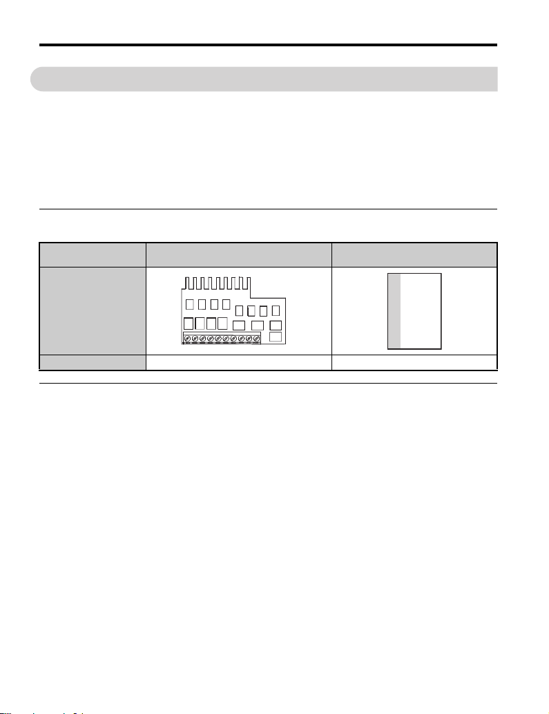
◆ DI-101 Option Package Contents
Description:
–
Quantity: 11
PCB 120 V Interface Card
UTC000450,RB
Installation Manual
◆ Tools Required for Installation
• A Phillips screwdriver (M3 metric / #1, #2 U.S. standard size) is required to install the
option.
• A straight-edge screwdriver (blade depth: 0.4 mm, width: 2.5 mm) is required to wire the
option terminal block.
Note: Tools required to prepare option cables for wiring are not listed in this manual.
8 YASKAWA TOEP YEAOPT 07 A1000 Option DI-101 120 Vac Interface Installation Manual
Page 9

4 Option Components
A
B
C
4 Option Components
◆ DI-101 Option
Figure 1
A – DI-101 120 V Interface Card
B – Option terminals (to drive)
C – Option terminal block (to control wiring)
Figure 1 DI-101 Option
◆ Option Terminal Block TB1
An 10-position terminal block is provided for the connection of 120 Vac and common signal
control wires.
Tab le 2 Option Terminal Functions
Terminal Functions
DI-101 Option Terminal Block Ter mi nal Signal Function Description
S1 Forward Run / Stop <1>
S2 Reverse Run / Stop <1>
S3 Multi-function Input <1>
S4 Multi-function Input <1>
S5 Multi-function Input <1>
S6 Multi-function Input <1>
S7 Multi-function Input <1>
S8 Multi-function Input <1>
X2 Common Control Input Common
X2 Common (spare) Control Input Common
<1> Terminal functions S1 to S8 may change based on drive programming.
Forward Run when closed,
stop when open (H1-01)
Reverse Run when closed,
stop when open (H1-02)
Multi-function contact inputs
(H1-03 to H1-08)
Signal
Level
120 Vac
±10 %
YAS KA WA TOEP YEAOPT 07 A1000 Option DI-101 120 Vac Interface Installation Manual 9
Page 10

5 Installation Procedure
W ARNING
5 Installation Procedure
◆ Section Safety
DANGER
Electric Shock Hazard
Do not connect or disconnect wiring while the power is on.
Failure to comply will result in death or serious injury.
Disconnect all power to the drive and wait at least the amount of time specified on the
drive front cover safety label. After all indicators are off, measure the DC bus voltage to
confirm safe level, and check for unsafe voltages. The internal capacitor remains charged
after the power supply is turned off.
Electrical Shock Hazard
Do not remove the front covers of the drive while the power is on.
Failure to comply could result in death or serious injury.
The diagrams in this section may include options and drives without covers or safety
shields to show details. Be sure to reinstall covers or shields before operating any devices.
Use the option according to the instructions described in this manual.
Do not allow unqualified personnel to use equipment.
Failure to comply could result in death or serious injury.
Maintenance, inspection, and replacement of parts must be performed only by authorized
personnel familiar with installation, adjustment, and maintenance of this product.
Do not touch circuit boards while the power to the drive is on.
Failure to comply could result in death or serious injury.
10 YASKAWA TOEP YEAOPT 07 A1000 Option DI-101 120 Vac Interface Installation Manual
Page 11

5 Installation Procedure
NOTICE
W ARNING
Do not use damaged wires, place excessive on wiring, or damage the wire insulation.
Failure to comply could result in death or serious injury.
Fire Hazard
Tighten all terminal screws to the specified tightening torque.
Loose electrical connections could result in death or serious injury by fire due to
overheating of electrical connections.
Damage to Equipment
Observe proper electrostatic discharge (ESD) procedures when handling the option,
drive, and circuit boards.
Failure to comply may result in ESD damage to circuitry.
Never shut the power off while the drive is running or outputting voltage.
Failure to comply may cause the application to operate incorrectly or damage the drive.
Do not operate damaged equipment.
Failure to comply may cause further damage to the equipment.
Do not connect or operate any equipment with visible damage or missing parts.
Do not use unshielded cable for control wiring.
Failure to comply may cause electrical interference resulting in poor system performance.
Use shielded twisted-pair wires and ground the shield to the ground terminal of the drive.
Properly connect all pins and connectors.
Failure to comply may prevent proper operation and possibly damage equipment.
Check wiring to ensure that all connections are correct after installing the option
and connecting any other devices.
Failure to comply may result in damage to the option.
YAS KA WA TOEP YEAOPT 07 A1000 Option DI-101 120 Vac Interface Installation Manual 11
Page 12

5 Installation Procedure
A
◆ Prior to Installing the Option
Prior to installing the option, wire the drive, make the necessary connections to the drive
terminals, and verify that the drive functions normally. Refer to the Quick Start Guide
packaged with the drive for information on wiring and connecting the drive.
Figure 2 is an exploded view of the drive with the option and related components for
reference.
Figure 2
E
D
C
A – A1000 Drive D – Terminal Cover
B – DI-101 Option E – A1000 TB1 - Digital Input Terminal Block,
C – Cover Screw
Figure 2 Drive Components with Option
12 YAS KA WA TOEP YEAOPT 07 A1000 Option DI-101 120 Vac Interface Installation Manual
B
Insertion Point for DI-101 Option
Page 13

5 Installation Procedure
D
C
◆ Installing the Option
Refer to the following instructions to install the option.
1. Shut off power to the drive, wait the appropriate amount of time for voltage to
dissipate. Remove the terminal cover screw (C) then remove the terminal cover (D).
Refer to the Quick Start Guide packaged with the drive for directions on removing
the cover. Cover removal varies depending on drive size.
DANGER! Electrical Shock Hazard. Disconnect all power to the drive and wait at least the amount of time
specified on the drive front cover safety label. After all indicators are off, measure the DC bus voltage to
confirm safe level, and check for unsafe voltages before servicing to prevent electric shock. The internal
capacitor remains charged even after the power supply is turned off.
NOTICE: Damage to Equipment. Observe proper electrostatic discharge procedures (ESD) when handling
the option, drive, and circuit boards. Failure to comply may result in ESD damage to circuitry.
Figure 3
Figure 3 Terminal Cover Removal
YAS KA WA TOEP YEAOPT 07 A1000 Option DI-101 120 Vac Interface Installation Manual 13
Page 14

5 Installation Procedure
TB1
2. Loosen terminals S1 to S8 and SN on the A1000 drive digital Input terminal block
Figure 4
TB1.
Figure 4 Loosen Drive Control Terminals TB1 S1 to S8 and SN
3. Remove the DI-101 option from the ESD bag.
NOTICE: When handling printed circuit boards (PCB) always use electrostatic discharge (ESD) protection.
Keep the boards in the ESD bag as long as you can. Do not lay the board on any surfaces without the ESD
protection. When handling, always hold the board from the edges and do not touch the components. Before
installing this option, a technically qualified individual, familiar with this type of equipment and the hazards
involved, should read this entire installation guide.
14 YAS KA WA TOEP YEAOPT 07 A1000 Option DI-101 120 Vac Interface Installation Manual
Page 15

5 Installation Procedure
4. Insert the DI-101 option (B) into the A1000 drive control terminals TB1, S1 to S8
and SN at the insertion point (E).
Refer to Figure 6 for the proper placement of the option terminals into the drive TB1
terminals. Secure the DI-101 option by tightening the TB1 terminals S1 to S8 and
SN. Refer to Wire Gauges, Tightening Torques, and Crimp Terminals on
Figure 5
page 20 to confirm that the proper tightening torque is applied to each terminal.
E
B
Figure 5 DI-101 Option Insertion into TB1
YAS KA WA TOEP YEAOPT 07 A1000 Option DI-101 120 Vac Interface Installation Manual 15
Page 16

5 Installation Procedure
DI-101
Option
A1000 Drive Terminals
Terminal Block
TB1
Wire Jumper
MA MB MC
M1 M2 M5
M3 M6 M4
E(G)
HC H1 H2 DM+ DM- IG R+ R- S+ S-
SC SP
V+ AC V- A1 A2 A3 FM AM AC MP RP AC
S1 S2 S3 S4 S5 S6 S7 S8 SN
S1 S2 S3 S4 S5 S6 S7 S8 SN
Figure 6
Figure 6 DI-101 Option to Drive Connection
5. Ensure the factory installed wire jumper is present between TB1 terminals SC to SP.
If no wire jumper is present, prepare and install a jumper according to Figure 7.
Route the customer-supplied option wiring through one of the cable glands on the
A1000 drive bottom conduit bracket.
16 YAS KA WA TOEP YEAOPT 07 A1000 Option DI-101 120 Vac Interface Installation Manual
Page 17

5 Installation Procedure
S1S2 S3S4 X2X2S8S7S6S5
DI-101 Option Terminal Block
Preparing wire ends:
Screwdriver blade size
about 5.5 mm (7/32”)
When not using
crimped insulated
sleeves
Strip wire insulation about 5.5 mm
and lightly twist the end with fingers,
keeping the ends from fraying.
Customer-supplied
120 Vac control circuit wires
(do not solder ends)
Loosen the screws and
insert the wire into the
opening on each terminal.
Blade depth of
0.4 mm or less
Blade width of
2.5 mm or less
6. Prepare the external 120 Vac control circuit wires (customer supplied) for terminals
Figure 7
S1 to S8 and X2 on the DI-101 option as shown in Figure 7.
Figure 7 Preparing Cable Wiring
7. Connect the customer wiring to the DI-101 option terminal block. Refer to Figure 8
for a wiring diagram example showing customer interface circuitry.
Refer to Wire Gauges, Tightening Torques, and Crimp Terminals on page 20 to
confirm that the proper tightening torque is applied to each terminal. Take particular
precaution to ensure each wire is properly connected and wire insulation is not
accidentally pinched into electrical terminals.
WARNING! Fire Hazard. Tighten terminal screws to the specified tightening torque. Loose electrical
connections could result in death or serious injury by fire due to overheating. Tightening screws beyond the
specified tightening torque may cause erroneous operation, damage the terminal block, or cause a fire.
YAS KA WA TOEP YEAOPT 07 A1000 Option DI-101 120 Vac Interface Installation Manual 17
Page 18

5 Installation Procedure
Figure 8
Customer Supplied Circuit
FWD
REV
S3
S4
S5
S6
S7
S8
120 Vac
X1
TB1
S1
S2
S3
S4
S5
S6
S7
S8
X2
X2
DI-101
120 Vac Interface
Option
Opto-Coupler
x8
3 mm Isolation
J2
Yaskawa A1000
AC Drive
S1
S1 Forward Run/Stop
S2
S2 Reverse Run/Stop
S3
S3 External fault
S4
S4 Fault reset
S5
S5 Multi-step speed 1
S6
S6 Multi-step speed 2
S7 Jog reference
S7
S8
S8 External baseblock
SN
Figure 8 Wiring Diagram Example
To ensure accurate control, use a stable 120 Vac power supply for the DI-101 input voltage
source.
18 YAS KA WA TOEP YEAOPT 07 A1000 Option DI-101 120 Vac Interface Installation Manual
Page 19

8. Replace terminal cover (D) and secure screw (C).
C
D
Figure 9
5 Installation Procedure
Figure 9 Replace the Terminal Cover
YAS KA WA TOEP YEAOPT 07 A1000 Option DI-101 120 Vac Interface Installation Manual 19
Page 20

5 Installation Procedure
d1
d2
6 mm
L
◆ Wire Gauges, Tightening Torques, and Crimp Terminals
■ Wire Gauges and Tightening Torques
Wire gauge and torque specifications are listed in Table 3.
Tab le 3 Wire Gauges and Tightening Torques
Ter mi nal
signal
S1 to S8
and X2
Screw
Size
M2
Tightening
Torque
N.m (in.lb)
0.22 to 0.25
(1.95 to 2.21)
(24 to 17 AWG)
(24 to 16 AWG)
■ Crimp Terminals
Yaskawa recommends using CRIMPFOX 6 by Phoenix Contact or equivalent crimp
terminals with the specifications listed in Table 4 for simplier and more reliable wiring.
Wire Gauge
2
mm
0.25 (24 AWG) AI 0.25 - 6YE 10.5 (13/32) 0.8 (1/32) 2 (5/64)
0.34 (22 AWG) AI 0.34 - 6TQ 10.5 (13/32) 0.8 (1/32) 2 (5/64)
0.5 (20 AWG) AI 0.5 - 6WH 14 (9/16) 1.1 (3/64) 2.5 (3/32)
Bare Cable Crimp Terminals
Applicable
Gauges mm
Stranded wire:
0.25 to 1.0
Solid wire:
0.25 to 1.5
Recomm.
2
Gauge mm
0.75
(18 AWG)
Applicable
2
Gauges mm
0.25 to 0.5
(24 to 20 AWG)
Tab le 4 Crimp Terminal Sizes
Phoenix Contact
Model
L
mm (in)
Recomm.
2
Gauge mm
(20 AWG)
d1
mm (in)
0.5
2
Stranded
or solid
d2
mm (in)
Wire
Typ e
wire
20 YAS KA WA TOEP YEAOPT 07 A1000 Option DI-101 120 Vac Interface Installation Manual
Page 21

6 Troubleshooting
6 Troubleshooting
Troubleshooting tips are provided below. Verify these points if the drive performance is not
as expected after installing the option:
• Verify all wire connections are tight.
• Verify all DI-101 PCB Fingers are fully inserted into the A1000 TB1 drive terminals and
the terminals are fully tightened.
• Verify the factory installed wire jumper is installed between A1000
TB1 terminals SC to SP.
• Verify the signal is present at the DI-101 option input terminals by using an AC voltmeter
to measure for a 120 Vac input signal is present on any activated terminals S1 thru S8 with
respect to the X2 terminal.
• Verify the digital input is recognized by the drive by viewing Input Terminal Status
monitor parameter U1-10.
• Verify the drive Multi-Function Digital Input parameters (H1-01 through H1-08) of the
drive are set correctly for the expected S1 to S8 input terminal behavior.
Preventing Noise Interference
Take the following steps to prevent erroneous operation caused by conducted electrical noise
interference:
• Use shielded wire for the signal lines less than 24 V.
• Limit the length of I/O signal wiring to less than 50 m (164 ft.).
• Use seperate conduits or cable tray separation for 120 Vac control wiring, DC signal and
other I/O wiring, main circuit power lines.
• Use noise suppression on relay coils.
• Ensure adequate system and drive grounding.
YAS KA WA TOEP YEAOPT 07 A1000 Option DI-101 120 Vac Interface Installation Manual 21
Page 22

7 Specifications
MANUAL NO. TOEP YEAOPT 07
Published in USA May 2011 11-5
Date of publication
Date of original publication
Revision number
1
7 Specifications
Tab le 5 Option Specifications
Specification Data
Inputs 8 Digital Inputs , +2 Neutral Common
Input Impedance 10 Kohms
On-State Voltage 93 to 132 Vac (110/120 Vac +10 % / -15 %)
On-State Current, Nominal 12.5 mA @ 120 Vac
Off-State Voltage, Maximum 19 Vac
Off-State Leakage Current, Maximum 4.0 mA
Operating Frequency 57 to 63 Hz (+/- 15 %)
On-State Response Time, Maximum 50 ms
Off-State Response Time, Maximum 50 ms
Terminal Wiring 16 AWG to 26 AWG
Area of Use Indoors
Operating Temperature -10 to +60 degrees C
Storage Temperature
Humidity 95% Relative Humidity or less (non condensing)
Revision History
Revision dates and manual numbers are located on the bottom of the back cover.
-20 to +85 degrees C
(short-term temperature during transport)
Date of
Publication
May 2011 −−First edition
Revision
Number
Section Revised Content
22 YASKAWA TOEP YEAOPT 07 A1000 Option DI-101 120 Vac Interface Installation Manual
Page 23

7 Specifications
YAS KA WA TOEP YEAOPT 07 A1000 Option DI-101 120 Vac Interface Installation Manual 23
Page 24

YASKAWA AC Drive-A1000 Option
DI-101 120 Vac Interface Option
Installation Manual
YASKAWA AMERICA, INC.
2121 Norman Drive South, Waukegan, IL 60085, U.S.A.
Phone: (800) YASKAWA (927-5292) or 1-847-887-7000 Fax: 1-847-887-7310
http://www.yaskawa.com
DRIVE CENTER (INVERTER PLANT)
2-13-1, Nishimiyaichi, Yukuhashi, Fukuoka, 824-8511, Japan
Phone: 81-930-25-3844 Fax: 81-930-25-4369
http://www.yaskawa.co.jp
YASKAWA ELECTRIC CORPORATION
New Pier Takeshiba South Tower, 1-16-1, Kaigan, Minatoku, Tokyo, 105-6891, Japan
Phone: 81-3-5402-4502 Fax: 81-3-5402-4580
http://www.yaskawa.co.jp
YASKAWA ELÉTRICO DO BRASIL LTDA.
Avenda Fagundes Filho, 620 Bairro Saude, São Paulo, SP04304-000, Brasil
Phone: 55-11-3585-1100
http://www.yaskawa.com.br
YASKAWA EUROPE GmbH
Hauptstrasse 185, 65760 Eschborn, Germany
Phone: 49-6196-569-300 Fax: 49-6196-569-398
http://www.yaskawa.eu.com
YASKAWA ELECTRIC UK LTD.
1 Hunt Hill Orchardton Woods, Cumbernauld, G68 9LF, United Kingdom
Phone: 44-1236-735000
http://www.yaskawa.co.uk
YASKAWA ELECTRIC KOREA CORPORATION
7F, Doore Bldg. 24, Yeoido-dong, Yeoungdungpo-gu, Seoul, 150-877, Korea
Phone: 82-2-784-7844
http://www.yaskawa.co.kr
YASKAWA ELECTRIC (SINGAPORE) PTE. LTD.
151 Lorong Chuan, #04-01, New Tech Park, 556741, Singapore
Phone: 65-6282-3003
http://www.yaskawa.com.sg
YASKAWA ELECTRIC (SHANGHAI) CO., LTD.
No. 18 Xizang Zhong Road, 17F, Harbour Ring Plaza, Shanghai, 200001, China
Phone: 86-21-5385-2200
http://www.yaskawa.com.cn
YASKAWA ELECTRIC (SHANGHAI) CO., LTD. BEIJING OFFICE
Room 1011, Tower W3 Oriental Plaza, No. 1 East Chang An Ave.,
Dong Cheng District, Beijing, 100738, China
Phone: 86-10-8518-4086
YASKAWA ELECTRIC TAIWAN CORPORATION
9F, 16, Nanking E. Rd., Sec. 3, Taipei, 104, Taiwan
Phone: 886-2-2502-5003
Fax: 55-11-5581-8795
Fax: 44-1236-458182
Fax: 82-2-784-8495
Fax: 65-6289-3003
Fax: 86-21-5385-3299
Fax: 86-10-8518-4082
Fax: 886-2-2505-1280
YASKAWA AMERICA, INC.
In the event that the end user of this product is to be the military and said product is to be employed in any weapons systems or the manufacture
thereof, the export will fall under the relevant regulations as stipulated in the Foreign Exchange and Foreign Trade Regulations. Therefore, be
sure to follow all procedures and submit all relevant documentation according to any and all rules, regulations and laws that may apply.
Specifications are subject to change without notice for ongoing product modifications and improvements.
© 2011 YASKAWA AMERICA, INC. All rights reserved.
MANUAL NO. TOEP YEAOPT 07
Published in USA May 2011 11-5
 Loading...