


Yashica TL Electro-X Service Manual
Table of Contents
• Foreward
• 1) Principles of Operation
o 1.1) Exposure readout circuit
o 1.2) Shutter Circuit
Principle of variation of the shutter speeds
Bulb exposure
o 1.3) ASA Film speed setting
• 2) Electical diagrams
o Schematic diagram
o Wiring diagram
• 3) Testing and measuring instruments
o Voltage stabilizer
o Insulating resistance meter
o Focal plane shutter tester
o Standard light source
• 4) Method of Repair
o 4.1) Battery checker circuit
4.1.1) Battery checker lamp fails to turn on
4.1.2) Improper voltage range
o 4.2) Malfunction of the exposure readout circuit
4.2.1) Both the "OVER" and "UNDER" indicator lamps fail to turn on
4.2.2) "UNDER" indicator lamp turns on normally, but "OVER" lamp fails to
light, or "OVER" lamp functions normally, but "UNDER" lamp fails to turn
on.
4.2.3) "OVER" indicator lamp turns on continuously and "UNDER" lamp fails
to turn on.
4.2.4) "UNDER" indicator lamp turns on continuously and "OVER" lamp fails
to alight.
4.2.5) Adjustment of the exposure readout circuit.
o 4.3) Shutter circuit
o 4.3.1) Shutter speed
o 4.3.2) Shutter remains open
o 4.3.3) Shutter closes automatically at "B" setting
o 4.3.4) Adjustment of the shutter speed

Foreward
This manual contains matters necessary for repair and servicing of the Yashica TL Electro-X.
The Yashica TL Electro-X incorporates the following functional features which make it completely
different from other focal shutter single-lens reflex cameras:
1. Thru-the-lens exposure readout system which does not require an exposure meter and
provides measurement of the correct exposure at stopped-down aperture through preselection
of either the lens aperture or shutter speed.
2. Electronic-controlled focal plane shutter affording an infinite range of intermediate shutter
speeds (and providing faithful function at 1/1000 sec. even when battery power is exhausted).
Its exposure readout and electronic shutter systems follow the pattern of those featured in the Lynx5000E (14E) and Electro 35, and their merits are outlined in their respective repair manuals.
Generally speaking, therefore, the Yashica TL Electro-X can be said to be an equipment which offer
all advantanges of the above-mentioned cameras.

Principles of operation
p
p
The circuitry of the Yashica TL Electo-X can be generally classified into the exposure readout
circuit, shutter circuit and battery checker circuit. The exposure readout circuit and the shutter
circuits are linked to each other with the aid of a slide resistor.
A coaxial dual variable resistor is employed for this purpose. Its top section forms the balancing
resistor (VR-1), while its bottom section functions as the shutter speed resistor (VR-2).
The circuit pattern consists of a combination of the exposure readout circuit of the Lynx-5000E
(14E) and the shutter circuit of the Electro 35, and correlation between the functions of these two
circuits is maintained through incorporation of the variable resistor.
1.1 Exposure Readout Circuit
The intensity of the light controlled by means of the diaphragm (exposure reading through
stopped-down) is sensed by the two CdS sensors incorporated in the pentaprism housing on both
sides of the viewfinder eyepiece.
Being a photoconductive cell, the CdS serves to vary the resistance value at a ratio inversely
roportional to the intensity of light to which it is exposed.
Because the CdS and the BALANCING resistor (VR-1) are series connected, the voltage from the
ower supply is affected by the degree of resistance offered by both and the voltage equivalent to
the VR-1 is applied to (T5)-(T1).
Both the OVER and UNDER indicator lamps fail to turn on (indicating correct exposure) when
the voltage range at (T5)-(T1) is between 0.6 V and 1.0 V. The OVER indicator lamp turns on
when the voltage rises above this level and the UNDER indicator lamp alights when it falls short
of this range. Consequently, the procedure for setting the correct exposure (indicated by the
OVER/UNDER lamps failing to turn on) consists of adjusting the VR-1 to a setting where a
voltage supply of 0.6 V to 1.0 V will be maintained at (T5)-(T1) as against the CdS resistance
value.
1.2 Simultaneously with the setting of the resistance value of the VR-1 through exposure readout, the
shutter speed resistor (VR-2) which is set coaxially is adjusted accordingly.
a. The trigger switch (SW-5) is adjusted to "ON" position when the shutter is charged.
b. When the shutter release button is depressed, the power switch (SW-2) on the shutter side is
turned on, setting the power supply to the circuit. At this stage, however, the Tr6 and Tr7 are at
"ON" position because Tr5 is turned off. Consequently, the magnet functions to hold the rear
sector of the shutter.
c. At the next stage, the trigger switch is turned off and the electric current controlled by the
setting of the shutter speed resistor begins to flow and the charging of the condensor C1 starts.
Immediately after the trigger switch is turned off, the front shutter sector is activated
mechanically and starts its function.
d. The electric potential of the condenser C1 rises gradually and, when it reaches a given (approx.
2.4 V), the Tr5 turns on and, simultaneously with this, the Tr6 and Tr7 are switched off. This
cuts off the supply of electric power to the magnet which then loses its force of attraction,
causing the rear sector to commence operation.
e. As soon as the rear sector completes its run over the entire picture area, the SW-2 is turned off,
thus cutting off the supply of the electric power to the shutter circuit and completing the shutter
operation.
Principle of variation of the shutter speeds
The shutter speed is decided through setting of the shutter speed resistor (VR-2).
If, for instance, only a very low resistance is offered by the VR-2, a large flow of electric

current is supplied to the condenser C1, necessitating only a very short period of time to charge
p
it to full capacity. In other words, the terminal voltage of the C1 rises to a given value within a
very short period of time, causing the rear sector to start to function with hardly any time delay
and thus providing fast exposure. If, on the other hand, a high resistance is offered, a restricted
flow of electric current is supplied, requiring a considerable period of time before the terminal
voltage of the C1 can reach level and thus providing long exposure.
Bulb Exposure
An insulating material is set between the 2 sec. and B settings of the resistor VR-2 and this
serves to distinguish between the normal shutter speed resistor and Bulb resistor. The SW-4
serves as this insulating material.
When the shutter speed control dial is adjusted to "B" setting, the brush of the VR-2 comes into
contact with the Bulb resistor.
The Bulb switch (SW-6) turns off when the shutter release button is depressed and turns on
when the pressure is released.
When the shutter speed control dial is adjusted to "B" setting and the shutter release button is
depressed, the bulb resistor and the brown lead wire are cut off from the plus circuit (pink) and,
therefore, no electric power is supplied to the condenser C1. Because the voltage at both
terminals of the C1 fails to rise, the normal switching of the transistors does not take place,
causing the magnet to hold the rear shutter all along.
When pressure on the shutter release button is released, the SW-6 is turned on. This sets the
flow of electric current through the Bulb resistor, starts the charging of the C1 and initiates the
switching of the transistors, causing the rear sector to be released from its original position and
thus closing the shutter.
The Bulb resistor does not wield any effect on the shutter function itself over the duration the
shutter release button is depressed. It is rather employed as a protection for the transistor, owing
to the fact that a huge flow of current is supplied to the base of the Tr5 when pressure on the
shutter button is released and the SW-6 is turned on. Without this resistor serving as a
rotection, the transistor is liable to be damaged due to the sudden high flow of electric current.
ASA film speed setting
The brush mounting ring of the BALANCING resistor (VR-1) is designed in such a manner as
to enable ready rotation other than through manipulation of the main spindle. In other words,
ASA film speed setting actually consists of rotating the VR-1 differentially without affecting
the function of the VR-2.
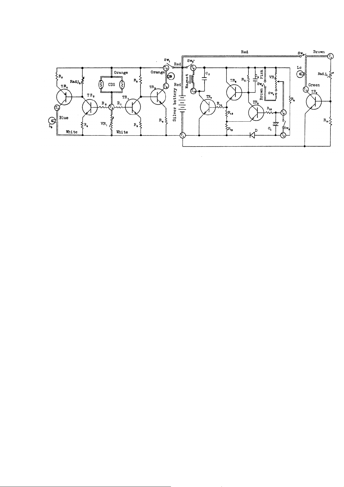
Schematic diagram of the Yashica TL Electro-X
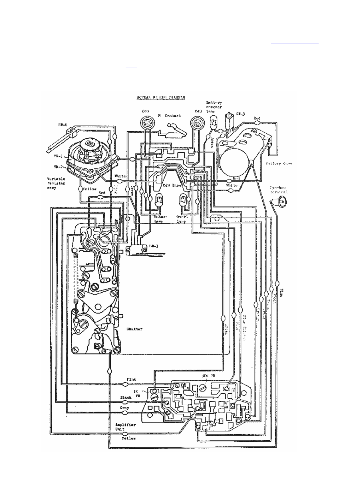
Yashica TL Electro-X wiring diagram
Table of contents
Here is a small (600x843) version of the diagram. It isn't all that legible but I was trying to keep the
file size down. You can click here for a larger (2017x2835, 168Kbyte, 300DPI) version of the
diagram. The larger version is suitable for printing at 300 DPI and should give an image 6.7 x 9.5
inches (17x24 cm).

Testing and Measuring Instruments
The use of the following instruments is recommended in inspection and repair of the Yashica TL
Electro-X:
Voltage Stabilzer
This instrument is indispensable to assuring high efficiency in repair and servicing. It is advisable
to use a voltage stablizer featuring a voltmeter and ampre-meter that provides ready checking and
reading of the output voltage and current. Moreover, teh use of a battery tool and lead wires
featuring clips at one end is recommended. By installing the battery tool in the battery chamber in
place of the mercury battery, electric power can be supplied readily from the voltage stabilizer.
Insulating Resistance Meter
This instrument which features an exclusive resistance scale permits reading of resistance over a
range of several megohms to several hundred megohms and is employed in the same manner as an
ordinary tester. Since it uses a high voltage power (approx. 500V), however, utmost precaution
must be exercised to prevent adverse effect on other circuits. In the course of use of this insulating
resistance meter, particular care must be taken to protect the transistors from the high-tension
supply.
Focal Plane Shutter tester
This instrument permits varied types of tests and measurements of the function of the focal plane
shutter, including the shutter speed (at the top, center and bottom of the picture area), speed of
operation of the front and rear sectors of the shutter, and time-lag of the X flash synchronizer
contact.
Standard Light Source
The standard light source is used for checking the exposure readout circuit. It is advisable to
incorporate this standard light source in the light value tester which is generally used for testing
and repair.

Methods of Repair
4.1 Battery checker circuit
4.1.1 Battery checker lamp fails to turn on.
4.1.1.1 Malfunction of the battery checker switch (SW-3). Undertake continuity test by
employing a tester.
4.1.1.2 Burn-out of the lamp filament.
Remove either one of the lamp terminals (brown or green) from the amplifier unit and
test the lamp for continuity with the aid of a tester. If no continuity is determined, it is an
indication of a lamp blow-out, necessitating lamp replacement.
4.1.1.3 Improper contact of the battery checker voltage regulating resistor (1K ohm semi-fixed
resistor) and malfunction of the transistors.
Install the battery, set the SW-3 to "ON" position and check the voltage of (T11) to (T1).
If the voltage is determined to be about the same level as that of the power source, it is
an indication of either an improper contact of the 1K ohm VR or a malfunction of the
transistors.
In this case, check the soldered ends of the 1K ohm VR. If both the soldered sections are
found to be in order, replace the amplifier unit.
4.1.2 Improper voltage range.
The battery checker lamp should normally turn on at a voltage range of over 3.8V and not
exceeding 4.2V under a temperature of 25°C. Since the battery checker circuit has a
temperature characteristics of -0.1V/+10°C when a temperature of 25°C is taken as a
standard, due consideration must be given to adjustment of the voltage range in accordance
with the temperature of the room in which the measurement is being taken. For instance,
under a temperature of 15°C, the voltage range will be 0.1V over the standard 25°C and will
therefore be over 3.9V and not exceeding 4.3V. On the other hand, the voltage range will be
over 3.7V and not exceeding 4.1V at a room temperature of 35°C.
4.1.2.1 Lighting voltage exceeds 4.2V.
This is attributed to improper adjustment of the battery checker voltage regulating
resistor (1K ohm VR), providing a resistance which is beyond the normal level. To
repair, turn the adjustment screw of the VR in a right motion and reduce the resistance to
an appropriate level.
4.1.2.2 Lighting voltage falls short of 3.8V
This is due to excessively low resistance of the 1K ohm VR. To repair, turn the
adjustment screw of the VR in a left motion and increase the resistance.
4.2 Malfunction of the exposure readout circuit
4.2.1 Both the "OVER" and "UNDER" indicator lamps fail to turn on.
4.2.1.1 Malfunction of the exposure readout switch (SW-1).
Test the SW-1 for continuity. Set the tester rods between the red and orange patterns of
the CdS baseplate and turn on the exposure readout activator switch. In case no
continuity is determined, it is an indication of either disconnection of the wiring,
improper adjustment of the switch contact pieces or accumulation of dust or other
foreign particles within the switch. To repair, check the wiring and clean the contact
pieces of the switch.
4.2.1.2 Malfunction of the amplifier unit.
If both the "OVER" and "UNDER" indicator lamps are found to be in normal working
condition and malfunction outlined in 4.2.1.1 cannot be determined, it is an indication of
a malfunction of the transistors featured in the unit. In such a case the entire unit must be
replaced.
4.2.2 "UNDER" indicator lamp turns on normally, but "OVER" lamp fails to light, or "OVER"
lamp functions normally, but "UNDER" lamp fails to turn on.
4.2.2.1 Burn-out of the "OVER" indicator lamp ("UNDER" indicator lamp).
Remove one of the terminals of the "OVER" (or "UNDER") indicator lamp and
undertake continuity test. If no continuity is determined, make replacement of the lamp.
4.2.2.2 Malfunction of the amplifier unit.
If the indicator lamps are found to be in order, it is an indication of a malfunction of the
transistors of the amplifier unit, necessitating replacement of the unit.
4.2.3 "OVER" indicator lamp turns on continuously and "UNDER" lamp fails to turn on.
This malfunction can be attributed to excessive rise in the electric potential of (T5)-(T1) due
to either shortcircuiting of the CdS or failure of the BALANCING resistor (VR-1) to
provide normal function. Normally, the voltage at (T5)-(T1) should be within the range of
0.6V and 1.0V at the point where both lamps turn off.
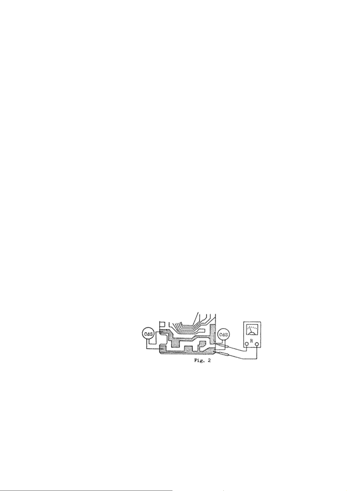
4.2.3.1 Shortcircuiting of the CdS.
Because shortcircuiting of the CdS itself is quite improbable, check whether or not the
CdS baseplate is shortcircuited.
Remove the blue lead wire of the amplifier unit on the CdS baseplate, apply the tester
rods between the colored patterns and undertake continuity test.
When the lens aperture is set manually to f/5.6 and a light emitted by a standard light
source is directed, each CdS should give the following resistance value (The reading
should be approximately half this figure in case measurement is taken of both CdS cells
simultaneously):
BLV 7 60 - 160K ohm
BLV 11 10 - 20K ohm
BLV 15 1.35 - 3.5K ohm
4.2.3.2 Failure of the BALANCING resistor (VR-1) to provide normal resistance function
Remove the blue lead wire of the VR-1 from the CdS baseplate and measure the
resistance value of the VR-1. In this case, the resistance reading should be within the
allowable limit specified in the chart given in Fig 4.2.3.1 [above].
4.2.3.3 Malfunction of the amplifier unit.
In case the voltage at (T5)-(T1) is determined to be normal, the cause can be attributed
to malfunction of the transistors, in which case the amplifier unit must be replaced.
4.2.4 "UNDER" indicator lamp turns on continuously and "OVER" lamp fails to alight.
This is due to either a decline in (T5)-(T1) voltage to almost 0V caused by shortcircuiting of
the VR-1 or failure of the CdS to provide normal resistance, or malfunction of the amplifier
unit.
4.2.4.1 Failure of the CdS unit to provide normal resistance.

Undertake continuity test according to procedure outlined in 4.2.3.1. The resistance
reading in this case should also correspond to that given in the same paragraph. If the
resistance is found to be excessive, remove one CdS cell at a time and check their
resistance individually. The resistance reading in this case should be within the
allowable limit specified in Fig. 2.3.1.
4.2.4.3 Shortcircuiting of the BALANCING resistor (VR-1)
Make through check according to procedure outlined in 4.2.3.2.
4.2.5 Adjustment of the exposure readout circuit.
Adjustment of the exposure readout circuit consists of either one of the following two
methods:
One method consists of loosening the two screws on top of the slide resistor assembly and
turning to offset resistor ring to alter its position in relation with the brush. This method
(providing a balanced shifting of the offset resistor characteristics) enables precise
regulation of the 'light turn-off point' without altering the 'light turn-off range'. The other
consists of adjustment of the 30K semi-fixed resistor incorporated in the amplifier unit. This
provides effective regulation of the 'light turn-off point' of the "OVER" indicator lamp.
4.2.5.1 Improper adjustment of the 'light turn-off' position.
i. The 'light turn-off' position generally tends to shift toward a direction providing
under-exposure at all light levels.
This malfunction is caused when the resistance of the offset resistor (VR-1) rises
to a level beyond the standard reading. To repair, turn the offset resistor ring in a
left motion to effect a balanced shifting of the resistor characteristics.
ii. The 'light turn-off' position generally tends to shift toward a direction providing
over-exposure at all light levels.
This malfunction is caused when the resistance of the BALANCING resistor
(VR-1) declines below the standard level. To make adjustment, turn the offset
resistor ring in a right motion.
4.2.5.2 The 'light turn-off' range is either excessive or too limited. The factory standard calls for
a 'light turn-off' range of 1/3 to 1-2/3 EV and, therefore, the following adjustment must
be made in case the range is determined to be excessive or too limited. Because this
range is adjusted on the basis of the function of the "OVER" indicator lamp, the VR-1
must be properly regulated in case it is determined after adjustment of the 'light turn-off
range' that the 'light turn-off point' has shifted from the normal position. (Refer to
pertinent details given later.)
i. Excessively wide 'light turn-off range'.
This can be attributed to adjustment of the 'light turn-off range' adjustment
resistor (30K ohm VR) to a resistance reading below the normal level. To repair,
turn the resistor in a left motion with the aid of a screw-driver to a setting that
provides higher resistance.
ii. The 'light turn-off' position generally tends to shift toward a direction providing
over-exposure at all light levels.

This malfunction is caused when the resistance of the BALANCING resistor
(VR-1) declines below the standard level. To make adjustment, turn the offset
resistor ring in a right motion.
4.2.5.3 In case both the 'light turn-off range' and 'light turn-off position' are determined to be not
up to standard. First of all, adjust the 'light turn-off' adjustment resistor (30K ohm) and
set the 'light turn-off range' to normal level. Then, adjust the BALANCING resistor
ring (VR-1) and set the 'light turn-off point' to the required position.
4.3 Shutter circuit
4.3.1 Shutter speed
4.3.1.1 Malfunction of the shutter power switch (SW-2)
In this case, the SW-2 fails to turn on. When using a DC voltage stabilzer, a flow of
electric current to the extent of about 30ma (at 5.5V) should be determined at the time
the shutter is released. Poor contact of the SW-2 is caused occasionally by
accumulation of dust or other foreign particles. To repair, therefore, wipe and clean the
contact pieces meticulously.
4.3.1.2 Disruption of the wiring of the electro-magnet.
Remove the black lead wire and undertake continuity test on the electro-magnet. The
resistance value should be approximately 270 ohms (with both electro-magnets).
4.3.1.3 Shortcircuiting of the shutter speed resistor (VR-2) circuit.
This can be attributed to either shortcircuiting of the shutter printed wiring panel or
shortcircuiting within the VR-2. In this case, remove the yellow or pink lead wire and
check the insulating resistance between the colored patterns. Also, undertake continuity
test of the VR-2.
The resistance of the VR-2 should be within the limit specified in Fig. 2.2.2.
4.3.1.4 Malfunction of the amplifier unit.
If everything is found to be in order after undertaking [the] thorough check outlined in
the preceeding three paragraphs, the cause can be pinpointed on malfunction of the
transistors, in which case the amplifier unit must be replaced.
4.3.2 Shutter remains open.
The shutter sectors remain open at "B" setting even after pressure on the shutter release
button is released. This is attributed to the fact that the electric potential of the charging
condenser (C1) fails to rise because either the shutter speed resistor (VR-2) or the trigger
switch (SW-5) does not reset to the "OFF" position.
4.3.2.1 Failure of the shutter resistor (VR-2) to provide normal resistance.
Check the resistance of the VR-2 according to the procedure outlined in 4.3.1.3. If no
continutiy is determined, it is an indication of a disconnection of the yellow or pink lead
wire or poor contact of the contact pieces of the VR-2.
4.3.2.2 The trigger switch (SW-5) fails to turn off.
Remove the gray lead wire from the shutter printed wiring panel and undertake
continuity test by setting the shutter to the "B" setting.
This test must be undertaken by setting the shutter control to either "B" or slow shutter
speed setting, because the SW-5 sets to "OFF" position only over the duration the
shutter remains open.
If it fails to set to "OFF" position, it is an indication of a malfunction of the SW-5;
therefore, make proper adjustment of its contact pieces. Because the position at which
the SW-5 sets to "OFF" position directly affects the exposure time (particularly in case
of high shutter speeds), the precise position where it turns off must be checked
meticulously after adjusting the contact pieces.
4.3.2.3 Malfunction of the amplifier unit.
If the shutter speed resistor and trigger switch are found to be in order, the cause can be
attributed to malfunction of the transistors, causing the shutter to remain open because

no electric current flows to the electro-magnet even if charging of the condenser (C1)
takes place. To repair, make replacement of the amplifier unit.
4.3.2.4 The shutter remains open only at "B" setting.
Undertake necessary check because this can be attributed to poor contact of the Bulb
switch (SW-6) or poor contact between the Bulb resistor of the VR-2 and the contact
piece.
4.3.3 Shutter closes automatically at "B" setting.
Specifically, this malfunction consists of the shutter closing automatically at "B" setting
while the shutter release button is being depressed or of the shutter functioning at speeds
faster than the normal at slow speeds (ranging from 1/8 to 1 sec.).
This is caused by improper insulation between the plus (pink) circuit and the "Bulb" resistor
incorporated in the shutter speed resistor (VR-2) as well as the brown lead wire circuit.
4.3.3.1 Poor insulation of the shutter speed resistor.
After adjusting the shutter speed control dial to 1/1000 sec. setting, check the insulating
resistance of both terminals of the "Bulb" switch (SW-6) with the aid of an insulating
resistance meter. The reading in this case should be 100 megohms or more.
The points where poor insulation may be caused most commonly are:
a. Soldered sections of the lead wires of the "Bulb" switch (SW-6) or improper
adjustment of the position of the contact pieces.
b. Soldered sections of the lead wires of the shutter speed resistor (VR-2).
c. Poor insulation of the "Bulb" resistor.
In case of (b) and (c) above, wipe and clean the pertinent parts carefully with lacquer
thinner.

4.3.3.2 Shutter function at about 8ms occasionally at "B" or settings slower than 1/125 sec.
There are times where the shutter functions at about 8ms [1/125 sec.] continuously or
once in about ten times.
This is caused because the shutter power switch (SW-2) is not held properly. In other
words, the SW-2 (red and pink) is shortcircuited on the shutter printed wiring panel. If,
after operating the shutter about twenty times, it provides normal function, it is an
indication that the activating lever of the SW-2 fails to hold the power switch-off lever.
In this case, replacement of the shutter is required.
4.3.4 Adjustment of the shutter speed.
In case the shutter functions either excessively fast or slow at all shutter speeds, proper
adjustment can be accomplished by turning the shutter speed resistor ring in the required
direction.
The adjustment screw on the base of the slide resistor assembly is linked directly to the
shutter speed resistor ring. By loosening this screw and turning it either to the left or right
along the guide slot, proper adjustment can be made.
4.3.4.1 Shutter functions at a speed faster than the normal rate.
This is caused when the resistance of the shutter speed resistor (VR-2) is set below the
normal level. Proper adjustment can be made by shifting the resistor in the direction to
the right of the main spindle when viewed from the bottom of the resistor itself.
4.3.4.2 The shutter functions at a speed slower than the normal rate.
This is caused when the resistance of the VR-2 is set beyond the normal level. To make
proper adjustment, turn the resistor ring in a left motion.
4.3.4.3 The shutter functions too fast at high speed settings and too slowly at slow speed
settings, or vice versa.
Because this can be attributed most commonly to the characteristics of the shutter speed
resistor (VR-2), check the resistance according to the procedure given in 4.3.1.3.
In case it is determined that the resistor fails to provide the normal characteristics,
replacement of the resistor is required because there is no effective means of adjustment.
 Loading...