


 Loading...
PROJECT GUIDE
MARINE AUXILIARY DIESEL ENGINE
MODEL 6EY18 Series
6EY18LW
6EY18ALW

Project Guide |
6EY18LW, 6EY18ALW |
Code No. 0GEY1-G00300 |
Marine Auxiliary Diesel Engine |
All Rights Reserved, Copyright

6EY18(A)LW |
46623 |
|
|
|
|
Marine Auxiliary Diesel Engine |
|
Page |
|
||
Contents |
|
1/3 |
|
|
|
00Introduction
01 Project Guide
02 Engine Model Name
03 Cylinder Layout and Operation Side
04 Direction of Rotation
05 Unit Conversion Table
06 Piping Symbols
01Outline
01 Major Specifications of Engine
02 Technical Data
03 Engine Performance
04 Power and Specific Fuel Consumption
05 Heat Balance
06 Measurement of Noise
07 Exhaust Gas Emissions
08 Unbalance Forces and Unbalance Momentums
09 Equipment for Use with H.F.O. Low Load Operation
10 Inspection and Maintenance Intervals
02Engine Structure
01 Engine External Appearance
02 Engine Sectional Drawings
03 Structural Outline
04 External Dimensions and Mass
05 Piping Connections
06 Disassembly and Maintenance Spaces
07 Mass and Dimensions of Major Parts
08 Material of Major Parts
09 Mass of Major Parts

6EY18(A)LW |
46623 |
|
|
|
|
Marine Auxiliary Diesel Engine |
|
Page |
|
||
Contents |
|
2/3 |
|
|
|
03Installation
01 Lifting Procedures
02 Layout of Generator Set
03 Installation of Generator Engine
04 Vibration Isolating Installation of Generator Engine
05 Crankshaft Deflection
10Air Charging and Exhaust System
01 Air Charging and Exhaust System
02 Turbocharger Compressor Water Cleaning Procedure
03 Turbocharger Turbine Cleaning Procedure
04 Selection of Exhaust Silencer
05 Exhaust Silencer
06 Rigging of Exhaust System
30Lubricating Oil System
01 Engine Lubricating Oil System
02 Priming Pump
03 Lubricating Oil Purification
04 Lubricating Oil Specifications
40Cooling Water System
01 Engine Cooling Water System
02 Inboard Cooling Water System
03 Warming Up System
04 Handling of Cooling Freshwater
50Fuel Oil System
01 Engine Fuel System
02 Fuel Supplying System
03 Fuel Pre-Treatment System
04 Fuel Quality Standard
05 Low-Sulfur Fuel
60Speed Control
01 Starting and Stopping Time Schedule
02 Governor

6EY18(A)LW |
46623 |
|
|
|
|
Marine Auxiliary Diesel Engine |
|
Page |
|
||
Contents |
|
3/3 |
|
|
|
70Starting and Control Air System
01 Starting and Control Air System
80Safety and Control Systems
01 Operation Data and Setting Values
02 Safety, Control and Monitoring
03 Communication with Generator Engine
04 Lubricating Oil Priming Pump Starter
81Generator
01 Drawing and Data
02 Coupling Type
03 Accessories
90Test
01 Shop Test Procedures of Generator Engine
91Spare Parts
01 Standard Spare Parts
02 Recommended Replacement Interval for Consumable Items
92Tools
01 Standard Tools
02 Special Tools
93Painting Colors and Name Plates 01 Painting Colors and Name Plates
99Storage Procedures
01 Long Storage Procedures
02 Maintenance after Installation
03 Starting after Long Term Storage
04 Storage Procedures for Spare Parts and Tools

00 Introduction
01 Project Guide
02 Engine Model Name
03 Cylinder Layout and Operation Side
04 Direction of Rotation
05 Unit Conversion Table
06 Piping Symbols
6EY18(A)LW

6EY18(A)LW |
|
46623 |
Introduction |
No. |
Page |
Project Guide |
00-01-00 |
1/1 |
|
|
|
zThis project guide was prepared as reference when planning the implementation of a Yanmar marine auxiliary diesel engine. Accordingly, no details of engine accessories are included; they are decided separately based on the subsequent consultations.
zThe power of this engine is assured under the following atmospheric and standard operational conditions:
|
|
Standard condition |
Service condition |
|
|
|
|
Ambient temperature |
°C |
25 |
0-45 |
|
|
|
|
Atmospheric pressure |
kPa (mmHg) |
100 (750) |
− |
|
|
|
|
Relative humidity |
% |
30 |
85 or below |
|
|
|
|
Air cooler inlet water temp. |
°C |
25 |
38 or below |
|
|
|
|
zThe unit system used in this Project Guide is based on the international unit system (SI).
zDue to improvements to the product and other reasons, the descriptions in this Project Guide are subject to change without prior notice.
Please check the specifications, performance, etc. of the product by the delivery specifications, drawings of finished product, operation manual and individual consultations.

6EY18(A)LW |
|
46623 |
Introduction |
No. |
Page |
Engine Model Name |
00-02-00 |
1/1 |
|
|
|
No. of cylinders
Name of engine series
Cylinder bore : cm
6 |
|
EY |
|
18 |
|
AL |
|
W |
|
|
|
|
|
|
|
|
|
Compliant with
IMO Tier 2 NOx regulations
AL : Marine Auxiliary (900, 1000 min-1)
L : Marine Auxiliary (720, 750 min-1)
041204-00E00
6EY18(A)LW |
|
46623 |
Introduction |
No. |
Page |
Cylinder Layout and Operation Side |
00-03-00 |
1/1 |
|
|
|
Cylinder Numbers: No.1,2,...counted from the flywheel side (main PTO side)
6 |
5 |
4 |
3 |
2 |
1 |
|
|
|
|
|
Flywheel |
|
|
|
|
|
017732-01E00 |
(Operation side)
Operation side: right side viewed from the opposite side of the flywheel
Non-operation side (Exhaust manifold side)
|
|
|
|
|
|
|
Flywheel |
|
|
|
|
Engine |
|
|
|
View |
6 |
5 |
4 |
3 |
2 |
1 |
Generator |
|
|||||||
|
|
|
|
|
|
|
Governor |
Operation side (Fuel injection pump case side)
017733-00E01
(Viewed from top)

6EY18(A)LW |
|
46623 |
Introduction |
No. |
Page |
Direction of Rotation |
00-04-00 |
1/1 |
|
|
|
Direction of Rotation: Counterclockwise viewed from flywheel side (Left Rotation).
Flywheel
017729-02E00

6EY18(A)LW |
|
46623 |
Introduction |
No. |
Page |
Unit Conversion Table |
00-05-00 |
1/1 |
|
|
|
Conversion values between the international unit system (SI) and the metric unit system are shown below:
Force |
|
|
|
|
|
|
|
N |
kgf |
Conversion Examples |
|
1 |
0.101972 |
1 N = 0.101972 kgf |
|
|
|
1 kgf = 9.80665 N |
|
9.80665 |
1 |
||
|
|
|
|
Moment of Force, Torque |
|
|
|
|
|
|
|
N m |
kgf m |
|
|
|
|
|
|
1 |
0.101972 |
|
|
|
|
|
|
9.80665 |
1 |
|
|
|
|
|
|
Pressure |
|
|
|
|
|
|
|
Pa |
kgf/cm2 |
mAq |
mmHg |
1 |
1.019710-5 |
1.019710-4 |
7.50110-3 |
9.80665104 |
1 |
1.000010 |
7.356102 |
9.80665103 |
1.000010-1 |
1 |
7.35610 |
1.3332102 |
1.359510-3 |
1.359510-2 |
1 |
Work, Energy |
|
|
|
|
|
|
|
kW h |
J |
kcal |
kgf m |
|
|
|
|
1 |
3.600106 |
8.600102 |
3.671105 |
2.77810-7 |
1 |
2.38910-4 |
1.019710-1 |
1.16310-3 |
4.186103 |
1 |
4.269102 |
2.72410-6 |
9.80665 |
2.34310-3 |
1 |
Work Efficiency, Power |
|
|
|
|
|
|
|
kW |
PS |
|
|
|
|
|
|
1 |
1.3596 |
|
|
|
|
|
|
0.7355 |
1 |
|
|
|
|
|
|
6EY18(A)LW |
|
46623 |
Introduction |
No. |
Page |
Piping Symbols |
00-06-00 |
1/1 |
|
|
|
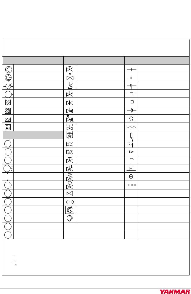
This Project Guide uses the following piping symbols.
Piping Diagram Codes
|
Equipment |
|
Valves |
|
Piping Parts |
|
Pump |
|
Globe valve |
|
Flange fitting |
|
Plunger pump |
|
Needle valve |
|
Shut-off valve |
|
Hand pump |
|
Angle valve |
|
Spectacle flange |
M |
Motor |
|
Butterfly valve |
|
Joint |
|
Strainer |
|
Sluice valve |
|
Boss |
|
Centrifugal strainer |
|
Screwed check valve |
|
Orifice |
AUTO |
Automatic backwash strainer |
|
Swing check valve |
|
Expansion joint |
|
|
|
|||
|
Porous plate strainer cylinder |
|
Piston valve |
|
Flexible pipe coupling |
|
Meter & Sensors |
|
Three-way piston valve |
|
Seal pot |
T |
Thermometer |
|
Cock |
|
Loop seal |
P |
Pressure gauge |
|
Three-way cock |
|
Reducer |
PD |
Differential pressure gauge |
|
Automatic pressure |
|
Air vent pipe |
|
regulating valve |
|
|||
P |
Oil signal |
|
Automatic temp. |
|
Safety plate |
|
regulating valve |
|
|||
|
Grazed level gauge |
|
Relief valve |
|
Accumulator |
PS |
Pressure switch |
S |
Solenoid valve |
|
Capillary tube |
|
|
||||
TS |
Temperature switch |
|
Pressure reducing valve |
CUT |
Copper pipe |
FS |
Float switch |
|
Duplex check valve |
STPG |
Carbon steel pipe |
|
for pressure tube |
||||
DPS |
Differential pressure SW |
|
Velocity regulating valve |
STKM |
Carbon steel pipe |
|
for high pressure tube |
||||
PT |
Pressure transmitter |
|
Flow volume regulating |
STS |
Machine structural |
|
valve |
carbon steel pipe |
|||
|
|
|
|
||
RB |
Resistance bulb |
|
|
O.D. |
Pipe outside diameter |
TC |
Thermocouple |
|
|
I.D. |
Pipe inner diameter |
Remark:
The black valve (globe valve, angle valve and needle valve) shows the constantly closed valve.
 : Opened constantly
 : Closed constantly
Piping parts marked with an asterisk ( ) are not included.
002887-01E00

01 Outline
01 Major Specifications of Engine
02 Technical Data
03 Engine Performance
04 Power and Specific Fuel Consumption
05 Heat Balance
06 Measurement of Noise
07 Exhaust Gas Emissions
08 Unbalance Forces and Unbalance Momentums
09Equipment for Use with H.F.O. Low Load Operation
10Inspection and Maintenance Intervals
6EY18(A)LW

6EY18(A)LW |
46623 |
|
|
Outline |
|
|
|
|
|
|
|
|
|
No. |
Page |
|
Major Specifications of Engine |
|
|
|
01-01-00 |
1/4 |
|||||||
|
|
|
|
|
|
|
|
|
|
|
|
|
1. Model 6EY18ALW (60 Hz, 900 min-1) |
|
|
|
|
|
|
|
|
|
|||
|
|
|
|
|
|
|
|
|
|
|
|
|
Model Name |
|
|
|
|
|
6EY18ALW |
|
|
|
|
||
|
|
|
|
|
|
|||||||
Type |
|
|
|
Vertical water-cooled 4 cycle diesel engine |
|
|||||||
|
|
|
|
|
|
|
|
|
|
|
|
|
No. of Cylinders |
|
|
|
|
|
|
6 |
|
|
|
|
|
|
|
|
|
|
|
|
|
|
|
|
|
|
Cylinder Bore¯Stroke |
mm |
|
|
|
|
180×280 |
|
|
|
|
||
|
|
|
|
|
|
|
|
|
|
|
||
Total Displacement |
l |
|
|
|
|
42.75 |
|
|
|
|
||
|
|
|
|
|
|
|
|
|
|
|
|
|
Continuous Rating |
kW |
800 |
745 |
|
680 |
660 |
|
615 |
550 |
|
500 |
455 |
|
|
|
|
|
|
|
|
|
|
|
|
|
Rated Speed |
min-1 |
|
|
|
|
900 |
|
|
|
|
||
Brake Mean Effective |
MPa |
2.495 |
2.323 |
|
2.121 |
2.057 |
|
1.918 |
1.716 |
|
1.560 |
1.420 |
Pressure |
|
|
|
|||||||||
|
|
|
|
|
|
|
|
|
|
|
|
|
|
|
|
|
|
|
|
|
|
|
|
|
|
Mean Piston Velocity |
m/s |
|
|
|
|
8.40 |
|
|
|
|
||
|
|
|
|
|
|
|
|
|
|
|
|
|
Power of |
kWe |
750 |
680 |
|
620 |
600 |
|
560 |
500 |
|
450 |
400 |
Generating Equip. * |
|
|
|
|
|
|
|
|
|
|
|
|
kVA |
937.5 |
850 |
|
775 |
750 |
|
700 |
625 |
|
562.5 |
500 |
|
|
|
|
|
|
|
|
|
|
|
|||
Overload Rating |
|
|
10% Overload: within 60 min (every 12 hours) |
|
||||||||
|
|
|
|
|||||||||
Crankshaft Revolving Direction |
|
Counterclockwise (viewed from the flywheel side) |
|
|||||||||
|
|
|
|
|
|
|
|
|
|
|
||
Firing Order |
|
|
|
|
|
1-4-2-6-3-5-1 |
|
|
|
|
||
|
|
|
|
|
||||||||
Operation Side |
|
|
Right side (viewed from the opposite side of the flywheel) |
|
||||||||
|
|
|
|
|
|
|
|
|
|
|
||
Combustion System |
|
|
|
|
|
Direct injection |
|
|
|
|
||
|
|
|
|
|
|
|
|
|
||||
Lubrication System |
|
|
|
|
Common bed incorporated sump |
|
|
|
||||
|
|
|
|
|
||||||||
Cooling System |
|
|
Freshwater and freshwater mixing dual cooling system |
|
||||||||
|
|
|
|
|
||||||||
Turbocharging System |
|
|
Exhaust gas turbine turbocharging with air cooler |
|
||||||||
|
|
|
|
|
|
|
|
|
|
|
||
Starting System |
|
|
|
|
|
Air starter |
|
|
|
|
||
|
|
|
|
|
|
|
|
|
|
|
||
Turning System |
|
|
|
|
|
Turning bar |
|
|
|
|
||
|
|
|
|
|
|
|
|
|
|
|
||
Lubricating Oil |
|
|
|
|
|
SAE30 or 40 |
|
|
|
|
||
|
|
|
|
|
|
|
|
|
|
|
|
|
Specific Fuel Consumption |
g/kW•h |
190+5% |
189+5% |
|
188+5% |
190+5% |
|
188+5% |
188+5% |
|
189+5% |
191+5% |
|
|
|
|
|
|
|
|
|
|
|
|
|
Specific Lubricating Oil |
g/kW•h |
|
|
|
|
0.3-1.1 |
|
|
|
|
||
Consumption |
|
|
|
|
|
|
|
|
||||
|
|
|
|
|
|
|
|
|
|
|
|
|
|
|
|
|
|
|
|
|
|
|
|
||
Engine Dry Weight |
kg |
|
|
|
|
6600 |
|
|
|
|
||
|
|
|
|
|
|
|
|
|
|
|
|
|
The specific fuel consumption shows the lower calorific value, 42.7 MJ/kg (10,200 kcal/kg), ISO3046/1, of a bare engine unit operated at 4/4 load and at rated speed and under the condition of complying with NOx emission regulation value (the tier 2 regulation) as required by IMO. When the engine-mounted lubricating oil pump is driven, 3 g/kW•h is added to the consumption and when the cooling water pump is driven, 1 g/kW•h is added to the consumption per one pump.
* The above generator capacity varies depending on actual generator efficiency.

6EY18(A)LW |
46623 |
|
|
Outline |
|
|
|
|
|
No. |
|
Page |
|
Major Specifications of Engine |
01-01-00 |
2/4 |
|||||||
|
|
|
|
|
|
|
|
|
|
2. Model 6EY18LW (60 Hz, 720 min-1) |
|
|
|
|
|
||||
|
|
|
|
|
|
|
|
|
|
Model Name |
|
|
|
|
6EY18LW |
|
|
|
|
|
|
|
|
|
|
|
|||
Type |
|
|
|
Vertical water-cooled 4 cycle diesel engine |
|
|
|||
|
|
|
|
|
|
|
|
|
|
No. of Cylinders |
|
|
|
|
6 |
|
|
|
|
|
|
|
|
|
|
|
|
|
|
Cylinder Bore¯Stroke |
mm |
|
|
|
180×280 |
|
|
|
|
|
|
|
|
|
|
|
|
|
|
Total Displacement |
l |
|
|
|
42.75 |
|
|
|
|
|
|
|
|
|
|
|
|
|
|
Continuous Rating |
kW |
615 |
|
550 |
500 |
450 |
|
|
400 |
|
|
|
|
|
|
|
|
|
|
Rated Speed |
min-1 |
|
|
|
720 |
|
|
|
|
Brake Mean Effective |
MPa |
2.397 |
|
2.144 |
1.949 |
1.754 |
|
1.560 |
|
Pressure |
|
|
|||||||
|
|
|
|
|
|
|
|
|
|
|
|
|
|
|
|
|
|
|
|
Mean Piston Velocity |
m/s |
|
|
|
6.72 |
|
|
|
|
|
|
|
|
|
|
|
|
|
|
Power of |
kWe |
560 |
|
500 |
450 |
400 |
|
|
360 |
Generating Equip. * |
|
|
|
|
|
|
|
|
|
kVA |
700 |
|
625 |
562.5 |
500 |
|
|
450 |
|
|
|
|
|
|
|
|
|
|
|
Overload Rating |
|
|
|
10% Overload: within 60 min (every 12 hours) |
|
|
|||
|
|
|
|
|
|||||
Crankshaft Revolving Direction |
|
Counterclockwise (viewed from the flywheel side) |
|
|
|||||
|
|
|
|
|
|
|
|
|
|
Firing Order |
|
|
|
|
1-4-2-6-3-5-1 |
|
|
|
|
|
|
|
|
|
|
||||
Operation Side |
|
|
Right side (viewed from the opposite side of the flywheel) |
|
|
||||
|
|
|
|
|
|
|
|
|
|
Combustion System |
|
|
|
|
Direct injection |
|
|
|
|
|
|
|
|
|
|
|
|||
Lubrication System |
|
|
|
Common bed incorporated sump |
|
|
|||
|
|
|
|
|
|
||||
Cooling System |
|
|
Freshwater and freshwater mixing dual cooling system |
|
|
||||
|
|
|
|
|
|
|
|||
Turbocharging System |
|
|
|
Exhaust gas turbine turbocharging with air cooler |
|
|
|||
|
|
|
|
|
|
|
|
|
|
Starting System |
|
|
|
|
Air starter |
|
|
|
|
|
|
|
|
|
|
|
|
|
|
Turning System |
|
|
|
|
Turning bar |
|
|
|
|
|
|
|
|
|
|
|
|
|
|
Lubricating Oil |
|
|
|
|
SAE30 or 40 |
|
|
|
|
|
|
|
|
|
|
|
|
|
|
Specific Fuel Consumption |
g/kW•h |
191+5% |
|
190+5% |
189+5% |
189+5% |
|
190+5% |
|
|
|
|
|
|
|
|
|
|
|
Specific Lubricating Oil |
g/kW•h |
|
|
|
0.3-1.1 |
|
|
|
|
Consumption |
|
|
|
|
|
|
|
||
|
|
|
|
|
|
|
|
|
|
|
|
|
|
|
|
|
|
|
|
Engine Dry Weight |
kg |
|
|
|
6600 |
|
|
|
|
|
|
|
|
|
|
|
|
|
|
The specific fuel consumption shows the lower calorific value, 42.7 MJ/kg (10,200 kcal/kg), ISO3046/1, of a bare engine unit operated at 4/4 load and at rated speed and under the condition of complying with NOx emission regulation value (the tier 2 regulation) as required by IMO. When the engine-mounted lubricating oil pump is driven, 3 g/kW•h is added to the consumption and when the cooling water pump is driven, 1 g/kW•h is added to the consumption per one pump.
* The above generator capacity varies depending on actual generator efficiency.
6EY18(A)LW |
46623 |
|
|
Outline |
|
|
|
|
|
|
|
|
|
No. |
Page |
|
Major Specifications of Engine |
|
|
|
01-01-00 |
3/4 |
|||||||
|
|
|
|
|
|
|
|
|
|
|
|
|
3. Model 6EY18ALW (50 Hz, 1000 min-1) |
|
|
|
|
|
|
|
|
|
|||
|
|
|
|
|
|
|
|
|
|
|
|
|
Model Name |
|
|
|
|
|
6EY18ALW |
|
|
|
|
||
|
|
|
|
|
|
|||||||
Type |
|
|
|
Vertical water-cooled 4 cycle diesel engine |
|
|||||||
|
|
|
|
|
|
|
|
|
|
|
|
|
No. of Cylinders |
|
|
|
|
|
|
6 |
|
|
|
|
|
|
|
|
|
|
|
|
|
|
|
|
|
|
Cylinder Bore¯Stroke |
mm |
|
|
|
|
180×280 |
|
|
|
|
||
|
|
|
|
|
|
|
|
|
|
|
||
Total Displacement |
l |
|
|
|
|
42.75 |
|
|
|
|
||
|
|
|
|
|
|
|
|
|
|
|
|
|
Continuous Rating |
kW |
800 |
745 |
|
680 |
660 |
|
615 |
550 |
|
500 |
455 |
|
|
|
|
|
|
|
|
|
|
|
|
|
Rated Speed |
min-1 |
|
|
|
|
1000 |
|
|
|
|
||
Brake Mean Effective |
MPa |
2.246 |
2.091 |
|
1.909 |
1.851 |
|
1.726 |
1.544 |
|
1.403 |
1.277 |
Pressure |
|
|
|
|||||||||
|
|
|
|
|
|
|
|
|
|
|
|
|
|
|
|
|
|
|
|
|
|
|
|
|
|
Mean Piston Velocity |
m/s |
|
|
|
|
9.33 |
|
|
|
|
||
|
|
|
|
|
|
|
|
|
|
|
|
|
Power of |
kWe |
750 |
680 |
|
620 |
600 |
|
560 |
500 |
|
450 |
400 |
Generating Equip. * |
|
|
|
|
|
|
|
|
|
|
|
|
kVA |
937.5 |
850 |
|
775 |
750 |
|
700 |
625 |
|
562.5 |
500 |
|
|
|
|
|
|
|
|
|
|
|
|||
Overload Rating |
|
|
10% Overload: within 60 min (every 12 hours) |
|
||||||||
|
|
|
|
|||||||||
Crankshaft Revolving Direction |
|
Counterclockwise (viewed from the flywheel side) |
|
|||||||||
|
|
|
|
|
|
|
|
|
|
|
||
Firing Order |
|
|
|
|
|
1-4-2-6-3-5-1 |
|
|
|
|
||
|
|
|
|
|
||||||||
Operation Side |
|
|
Right side (viewed from the opposite side of the flywheel) |
|
||||||||
|
|
|
|
|
|
|
|
|
|
|
||
Combustion System |
|
|
|
|
|
Direct injection |
|
|
|
|
||
|
|
|
|
|
|
|
|
|
||||
Lubrication System |
|
|
|
|
Common bed incorporated sump |
|
|
|
||||
|
|
|
|
|
||||||||
Cooling System |
|
|
Freshwater and freshwater mixing dual cooling system |
|
||||||||
|
|
|
|
|
||||||||
Turbocharging System |
|
|
Exhaust gas turbine turbocharging with air cooler |
|
||||||||
|
|
|
|
|
|
|
|
|
|
|
||
Starting System |
|
|
|
|
|
Air starter |
|
|
|
|
||
|
|
|
|
|
|
|
|
|
|
|
||
Turning System |
|
|
|
|
|
Turning bar |
|
|
|
|
||
|
|
|
|
|
|
|
|
|
|
|
||
Lubricating Oil |
|
|
|
|
|
SAE30 or 40 |
|
|
|
|
||
|
|
|
|
|
|
|
|
|
|
|
|
|
Specific Fuel Consumption |
g/kW•h |
196+5% |
195+5% |
|
194+5% |
193+5% |
|
193+5% |
197+5% |
|
198+5% |
198+5% |
|
|
|
|
|
|
|
|
|
|
|
|
|
Specific Lubricating Oil |
g/kW•h |
|
|
|
|
0.3-1.1 |
|
|
|
|
||
Consumption |
|
|
|
|
|
|
|
|
||||
|
|
|
|
|
|
|
|
|
|
|
|
|
|
|
|
|
|
|
|
|
|
|
|
||
Engine Dry Weight |
kg |
|
|
|
|
6600 |
|
|
|
|
||
|
|
|
|
|
|
|
|
|
|
|
|
|
The specific fuel consumption shows the lower calorific value, 42.7 MJ/kg (10,200 kcal/kg), ISO3046/1, of a bare engine unit operated at 4/4 load and at rated speed and under the condition of complying with NOx emission regulation value (the tier 2 regulation) as required by IMO. When the engine-mounted lubricating oil pump is driven, 3 g/kW•h is added to the consumption and when the cooling water pump is driven, 1 g/kW•h is added to the consumption per one pump.
* The above generator capacity varies depending on actual generator efficiency.

6EY18(A)LW |
46623 |
|
|
Outline |
|
|
|
|
|
No. |
|
Page |
|
Major Specifications of Engine |
01-01-00 |
4/4 |
|||||||
|
|
|
|
|
|
|
|
|
|
4. Model 6EY18LW (50 Hz, 750 min-1) |
|
|
|
|
|
||||
|
|
|
|
|
|
|
|
|
|
Model Name |
|
|
|
|
6EY18LW |
|
|
|
|
|
|
|
|
|
|
|
|||
Type |
|
|
|
Vertical water-cooled 4 cycle diesel engine |
|
|
|||
|
|
|
|
|
|
|
|
|
|
No. of Cylinders |
|
|
|
|
6 |
|
|
|
|
|
|
|
|
|
|
|
|
|
|
Cylinder Bore¯Stroke |
mm |
|
|
|
180×280 |
|
|
|
|
|
|
|
|
|
|
|
|
|
|
Total Displacement |
l |
|
|
|
42.75 |
|
|
|
|
|
|
|
|
|
|
|
|
|
|
Continuous Rating |
kW |
615 |
|
550 |
500 |
450 |
|
|
400 |
|
|
|
|
|
|
|
|
|
|
Rated Speed |
min-1 |
|
|
|
750 |
|
|
|
|
Brake Mean Effective |
MPa |
2.302 |
|
2.058 |
1.871 |
1.684 |
|
1.497 |
|
Pressure |
|
|
|||||||
|
|
|
|
|
|
|
|
|
|
|
|
|
|
|
|
|
|
|
|
Mean Piston Velocity |
m/s |
|
|
|
7.00 |
|
|
|
|
|
|
|
|
|
|
|
|
|
|
Power of |
kWe |
560 |
|
500 |
450 |
400 |
|
|
360 |
Generating Equip. * |
|
|
|
|
|
|
|
|
|
kVA |
700 |
|
625 |
562.5 |
500 |
|
|
450 |
|
|
|
|
|
|
|
|
|
|
|
Overload Rating |
|
|
|
10% Overload: within 60 min (every 12 hours) |
|
|
|||
|
|
|
|
|
|||||
Crankshaft Revolving Direction |
|
Counterclockwise (viewed from the flywheel side) |
|
|
|||||
|
|
|
|
|
|
|
|
|
|
Firing Order |
|
|
|
|
1-4-2-6-3-5-1 |
|
|
|
|
|
|
|
|
|
|
||||
Operation Side |
|
|
Right side (viewed from the opposite side of the flywheel) |
|
|
||||
|
|
|
|
|
|
|
|
|
|
Combustion System |
|
|
|
|
Direct injection |
|
|
|
|
|
|
|
|
|
|
|
|||
Lubrication System |
|
|
|
Common bed incorporated sump |
|
|
|||
|
|
|
|
|
|
||||
Cooling System |
|
|
Freshwater and freshwater mixing dual cooling system |
|
|
||||
|
|
|
|
|
|
|
|||
Turbocharging System |
|
|
|
Exhaust gas turbine turbocharging with air cooler |
|
|
|||
|
|
|
|
|
|
|
|
|
|
Starting System |
|
|
|
|
Air starter |
|
|
|
|
|
|
|
|
|
|
|
|
|
|
Turning System |
|
|
|
|
Turning bar |
|
|
|
|
|
|
|
|
|
|
|
|
|
|
Lubricating Oil |
|
|
|
|
SAE30 or 40 |
|
|
|
|
|
|
|
|
|
|
|
|
|
|
Specific Fuel Consumption |
g/kW•h |
192+5% |
|
192+5% |
191+5% |
192+5% |
|
194+5% |
|
|
|
|
|
|
|
|
|
|
|
Specific Lubricating Oil |
g/kW•h |
|
|
|
0.3-1.1 |
|
|
|
|
Consumption |
|
|
|
|
|
|
|
||
|
|
|
|
|
|
|
|
|
|
|
|
|
|
|
|
|
|
|
|
Engine Dry Weight |
kg |
|
|
|
6600 |
|
|
|
|
|
|
|
|
|
|
|
|
|
|
The specific fuel consumption shows the lower calorific value, 42.7 MJ/kg (10,200 kcal/kg), ISO3046/1, of a bare engine unit operated at 4/4 load and at rated speed and under the condition of complying with NOx emission regulation value (the tier 2 regulation) as required by IMO. When the engine-mounted lubricating oil pump is driven, 3 g/kW•h is added to the consumption and when the cooling water pump is driven, 1 g/kW•h is added to the consumption per one pump.
* The above generator capacity varies depending on actual generator efficiency.
6EY18(A)LW |
46623 |
|
|
|
Outline |
Technical Data (900 min-1) |
|
|
|
|
|
|
|
No. |
Page |
|||||||||||||
|
|
|
|
|
|
|
|
01-02-00 |
1/4 |
|
||||||||||||||
|
1. Model 6EY18ALW (900 min-1) |
|
|
|
|
|
|
|
|
|
|
|
|
|
|
|
|
|
|
|
||||
|
Pumps |
|
|
|
|
|
|
|
|
|
|
|
|
|
|
|
|
|
|
|
|
|
|
|
|
Cooling Water Pump (High temp) |
Centrifugal |
|
27 m3/h |
|
|
|
20 m |
|
|
|
|
Eng. mount |
|
|
|||||||||
|
Cooling Water Pump (Low temp) |
Centrifugal |
|
27 m3/h |
|
|
|
20 m |
|
|
|
|
Eng. mount |
|
|
|||||||||
|
Fuel Feed Pump for M.D.O. |
Gear type |
|
0.623 m3/h |
|
Refer to 50-02 |
|
|
|
Eng. mount |
|
|
||||||||||||
|
Fuel Supply Pump for H.F.O. |
Gear type |
|
- |
|
|
Refer to 50-02 |
|
|
|
|
Hull mount |
|
|
||||||||||
|
Lubricating Oil Pump |
Gear type |
|
21.4 m3/h |
|
|
0.80 MPa |
|
|
|
|
Eng. mount |
|
|
||||||||||
|
Lubricating Oil Priming Pump |
Gear type |
|
|
4 m3/h |
|
|
0.15 MPa |
|
|
|
|
Eng. mount |
|
|
|||||||||
|
Strainers |
|
|
|
|
|
|
|
|
|
|
|
|
|
|
|
|
|
|
|
|
|
|
|
|
Fuel Strainer (Eng. Inlet) |
Duplex change over, |
|
|
E.F. 35 μm |
|
|
|
|
Eng. mount |
|
|
||||||||||||
|
|
|
notch wire |
|
|
|
|
|
|
|
|
|||||||||||||
|
|
|
|
|
|
|
|
|
|
|
|
|
|
|
|
|
|
|
|
|||||
|
Fuel Strainer (For H.F.O. Circulate) |
Duplex change over, |
|
|
E.F. 10 μm |
|
|
|
|
|
Hull mount |
|
|
|||||||||||
|
automatic backwashing |
|
|
|
|
|
|
|
|
|
||||||||||||||
|
|
|
|
|
|
|
|
|
|
|
|
|
|
|
|
|
|
|||||||
|
Fuel Strainer (For FCC) |
(Recommend) Fine Strainer |
|
|
E.F. 5 μm |
|
|
|
|
|
Hull mount |
|
|
|||||||||||
|
Lubricating Oil |
Common Bed |
Perforated Steel Plate |
|
|
- |
|
|
|
Assembled in common bed |
|
|||||||||||||
|
Primary Strainer |
Incorporated Sump |
|
|
|
|
|
|
||||||||||||||||
|
|
|
|
|
|
|
|
|
|
|
|
|
|
|
|
|
|
|
|
|
|
|||
|
Secondary Lubricating Oil Strainer |
Automatic backwashing |
|
35 μm (E.F. 30 μm) |
|
|
|
Eng. mount |
|
|
||||||||||||||
|
Coolers |
|
|
|
|
|
|
|
|
|
|
|
|
|
|
|
|
|
|
|
|
|
|
|
|
Lubricating Oil Cooler |
Multi-tubular with fins |
|
|
|
8.7 m2 |
|
|
|
|
Eng. mount |
|
|
|||||||||||
|
Air Cooler |
|
Multi-tubular with plate fins |
|
|
|
24.6 m2 |
|
|
|
|
Eng. mount |
|
|
||||||||||
|
Temperature Regulating Valves |
|
|
|
|
|
|
|
|
|
|
|
|
|
|
|
|
|
|
|
|
|
||
|
|
|
|
|
|
|
|
|
|
|
|
• Engine power: 745/800 kW |
|
|
|
|
|
|
|
|
||||
|
|
|
|
|
|
|
|
|
|
|
|
Load 65% or above: 60°C±4°C |
|
|
|
|
|
|
|
|
||||
|
Freshwater Regulating Valve for |
Direct-action, wax-pellet, |
|
Load less than 65%: 85°C±4°C |
|
|
|
|
|
|
|
|
||||||||||||
|
|
• Engine power: 660/680 kW |
|
|
|
Eng. mount |
|
|
||||||||||||||||
|
High Temperature |
regulating at outlet |
|
Load 75% or above: 60°C±4°C |
|
|
|
|
|
|||||||||||||||
|
|
|
|
|
|
|
|
|
|
|||||||||||||||
|
|
|
|
|
|
|
|
|
|
|
|
Load less than 75%: 85°C±4°C |
|
|
|
|
|
|
|
|
||||
|
|
|
|
|
|
|
|
|
|
|
|
• 445-615 kW |
|
|
|
|
|
|
|
|
|
|||
|
|
|
|
|
|
|
|
|
|
|
|
85°C±4°C |
|
|
|
|
|
|
|
|
|
|||
|
Lubricating Oil Temp. Regulating Valve |
Direct-action, wax-pellet |
|
|
|
50-65 |
|
|
|
|
Eng. mount |
|
|
|||||||||||
|
Tanks |
|
|
|
|
|
|
|
|
|
|
|
|
|
|
|
|
|
|
|
|
|
|
|
|
Lubricating Oil Tank Capacity |
|
|
|
|
|
|
|
|
|
See 30-01-00 |
|
|
|
|
|
|
|
||||||
|
Engine Freshwater Holding Capacity |
|
|
|
|
|
|
|
|
|
|
145 l |
|
|
|
|
|
|
|
|
|
|||
|
|
|
|
|
|
|
|
|
|
|
|
|
|
|
|
|
|
|||||||
|
Starting Air Sump |
|
|
|
|
|
|
|
150 l× 1 Bottle, 2.94 MPa |
|
|
|
|
|||||||||||
|
|
|
|
|
|
|
|
|
|
|
|
|
|
|
|
|
|
|
|
|
|
|
|
|
|
Other Data |
|
|
|
|
|
|
|
|
|
|
|
|
|
|
|
|
|
|
|
|
|
|
|
|
Continuous Rating Power |
kW |
|
800 |
|
745 |
|
680 |
|
660 |
|
615 |
|
|
550 |
|
500 |
455 |
|
|||||
|
Radiation |
Heat Radiation to L.O. (at 100% Load) |
MJ/h |
|
350.4 |
|
337.9 |
|
323.2 |
|
318.7 |
|
292.7 |
|
|
275.5 |
|
262.3 |
250.4 |
|
||||
|
Heat Radiation to Low Temp. C.W. |
MJ/h |
|
203.4 |
|
178.6 |
|
149.2 |
|
140.1 |
|
216.4 |
|
|
187.6 |
|
167.5 |
150.9 |
|
|||||
|
|
|
|
|
|
|
|
|
|
|
||||||||||||||
|
|
(at 100% Load) |
|
|
|
|
|
|
|
|
|
|||||||||||||
|
|
|
|
|
|
|
|
|
|
|
|
|
|
|
|
|
|
|
|
|
|
|
||
|
Heat |
Heat Radiation to High Temp. C.W. |
MJ/h |
|
785.3 |
|
714.4 |
|
630.6 |
|
604.8 |
|
567.0 |
|
|
461.2 |
|
384.0 |
319.1 |
|
||||
|
(at 100% Load) |
|
|
|
|
|
|
|
|
|
|
|
|
|
|
|
|
|
|
|
|
|
||
|
|
|
|
|
|
|
|
|
|
|
|
|
|
|
|
|
|
|
|
|
|
|
||
|
|
Heat Radiation to Air (at 100% Load) |
MJ/h |
|
797.0 |
|
742.2 |
|
677.5 |
|
657.5 |
|
532.3 |
|
|
492.2 |
|
461.3 |
433.5 |
|
||||
|
Combustion Air Volume at 100% Load [25°C] |
m3/h |
|
4510 |
|
4320 |
|
4080 |
|
4060 |
|
3760 |
|
|
3600 |
|
3370 |
3100 |
|
|||||
|
Exh. Gas Volume at 100% Load [0°C] |
m3/h |
|
4060 |
|
3880 |
|
3730 |
|
3720 |
|
3480 |
|
|
3320 |
|
3090 |
2860 |
|
|||||
|
Eng. Room Ventilation Air Volume |
|
|
|
|
|
|
|
|
|
0.27-0.41 m3/min kW |
|
|
|
|
|||||||||
|
T/C Outlet Exh. Gas Temp. |
°C |
|
370 |
|
360 |
|
350 |
|
350 |
|
350 |
|
|
340 |
|
335 |
330 |
|
|||||
|
(at 100% Load, Ambient Temp. 25°C) |
|
|
|
|
|
|
|
|
|
||||||||||||||
|
|
|
|
|
|
|
|
|
|
|
|
|
|
|
|
|
|
|
|
|
|
|||
|
Exh. Back Pressure at 100% Load |
|
|
|
|
|
|
|
|
|
|
3.43 kPa |
or below |
|
|
|
|
|
|
|
||||
|
Exhaust Pipe Diameter |
|
|
|
|
|
|
|
|
|
|
250 A or 300 A |
|
|
|
|
|
|
|
|||||
|
|
|
|
|
|
|
|
|
|
|
|
|
|
|
|
|
|
|
|
|
|
|
|
|

6EY18(A)LW |
46623 |
|
|
|
Outline |
Technical Data (720 min-1) |
|
|
|
|
No. |
Page |
||||||||||
|
|
|
|
|
|
01-02-00 |
2/4 |
|
||||||||||
|
2. Model 6EY18LW (720 min-1) |
|
|
|
|
|
|
|
|
|
|
|
|
|
||||
|
Pumps |
|
|
|
|
|
|
|
|
|
|
|
|
|
|
|
|
|
|
Cooling Water Pump (High temp) |
Centrifugal |
|
21 m3/h |
|
|
|
16 m |
|
|
Eng. mount |
|
||||||
|
Cooling Water Pump (Low temp) |
Centrifugal |
|
21 m3/h |
|
|
|
16 m |
|
|
Eng. mount |
|
||||||
|
Fuel Feed Pump for M.D.O. |
Gear type |
|
0.499 m3/h |
|
|
Refer to 50-02 |
|
|
Eng. mount |
|
|||||||
|
Fuel Supply Pump for H.F.O. |
Gear type |
|
- |
|
|
|
Refer to 50-02 |
|
|
Hull mount |
|
||||||
|
Lubricating Oil Pump |
Gear type |
|
27.3 m3/h |
|
|
0.80 MPa |
|
|
Eng. mount |
|
|||||||
|
Lubricating Oil Priming Pump |
Gear type |
|
4 m3/h |
|
|
0.15 MPa |
|
|
Eng. mount |
|
|||||||
|
Strainers |
|
|
|
|
|
|
|
|
|
|
|
|
|
|
|
|
|
|
Fuel Strainer (Eng. Inlet) |
Duplex change over, |
|
|
E.F. 35 μm |
|
|
Eng. mount |
|
|||||||||
|
|
notch wire |
|
|
|
|
|
|||||||||||
|
|
|
|
|
|
|
|
|
|
|
|
|
|
|
||||
|
Fuel Strainer (For H.F.O. Circulate) |
Duplex change over, |
|
|
E.F. 10 μm |
|
|
Hull mount |
|
|||||||||
|
automatic backwashing |
|
|
|
|
|
||||||||||||
|
|
|
|
|
|
|
|
|
|
|
|
|
|
|||||
|
|
|
|
|
|
|
|
|
|
|
|
|
|
|
||||
|
Fuel Strainer (For FCC) |
(Recommend) Fine Strainer |
|
|
E.F. 5 μm |
|
|
Hull mount |
|
|||||||||
|
Lubricating Oil |
Common Bed |
Perforated Steel Plate |
|
|
- |
|
Assembled in common bed |
|
|||||||||
|
Primary Strainer |
Incorporated Sump |
|
|
|
|
||||||||||||
|
|
|
|
|
|
|
|
|
|
|
|
|
|
|
|
|||
|
|
|
|
|
|
|
|
|
|
|
|
|
|
|
|
|||
|
Secondary Lubricating Oil Strainer |
Automatic backwashing |
|
35 μm (E.F. 30 μm) |
|
|
Eng. mount |
|
||||||||||
|
Coolers |
|
|
|
|
|
|
|
|
|
|
|
|
|
|
|
|
|
|
Lubricating Oil Cooler |
Multi-tubular with fins |
|
|
8.7 m2 |
|
|
Eng. mount |
|
|||||||||
|
Air Cooler |
|
Multi-tubular with plate fins |
|
24.6 m2 |
|
|
Eng. mount |
|
|||||||||
|
Temperature Regulating Valves |
|
|
|
|
|
|
|
|
|
|
|
|
|
|
|
||
|
|
|
|
|
|
|
|
|
|
• 550-615 kW |
|
|
|
|
|
|
||
|
Freshwater Regulating Valve for |
Direct-action, wax-pellet, |
|
Load 75%±5% or above: 60°C±4°C |
|
|
Eng. mount |
|
||||||||||
|
|
Load less than 75%±5%: 85°C±4°C |
|
|
|
|||||||||||||
|
High Temperature |
regulating at outlet |
|
|
|
|
||||||||||||
|
|
• 400-500 kW |
|
|
|
|
|
|
||||||||||
|
|
|
|
|
|
|
|
|
|
|
|
|
|
|
|
|||
|
|
|
|
|
|
|
|
|
|
85°C±4°C |
|
|
|
|
|
|
||
|
|
|
|
|
|
|
|
|
|
|
|
|
|
|
||||
|
Lubricating Oil Temp. Regulating Valve |
Direct-action, wax-pellet |
|
|
50-65°C |
|
|
Eng. mount |
|
|||||||||
|
Tanks |
|
|
|
|
|
|
|
|
|
|
|
|
|
|
|
|
|
|
Lubricating Oil Tank Capacity |
|
|
|
|
|
|
|
See 30-01-00 |
|
|
|
|
|
||||
|
Engine Freshwater Holding Capacity |
|
|
|
|
|
|
|
|
145 l |
|
|
|
|
|
|||
|
|
|
|
|
|
|
|
|
|
|
|
|
|
|||||
|
Starting Air Sump |
|
|
|
|
|
150 l× 1 Bottle, 2.94 MPa |
|
|
|||||||||
|
|
|
|
|
|
|
|
|
|
|
|
|
|
|
|
|
|
|
|
Other Data |
|
|
|
|
|
|
|
|
|
|
|
|
|
|
|
|
|
|
|
|
|
|
|
|
|
|
|
|
|
|
|
|
||||
|
Continuous Rating Power |
kW |
|
615 |
|
550 |
|
500 |
|
450 |
|
400 |
|
|||||
|
Radiation |
Heat Radiation to L.O. (at 100% Load) |
MJ/h |
|
280.3 |
|
266.3 |
|
229.0 |
|
224.4 |
|
224.4 |
|
||||
|
Heat Radiation to Low Temp. C.W. |
MJ/h |
|
184.6 |
|
162.3 |
|
141.4 |
|
129.4 |
|
129.4 |
|
|||||
|
|
|
|
|
|
|
|
|||||||||||
|
|
(at 100% Load) |
|
|
|
|
|
|
||||||||||
|
|
|
|
|
|
|
|
|
|
|
|
|
|
|
|
|
||
|
|
|
|
|
|
|
|
|
|
|
|
|
|
|
|
|
|
|
|
Heat |
Heat Radiation to High Temp. C.W. |
MJ/h |
|
571.4 |
|
492.7 |
|
359.4 |
|
306.2 |
|
306.2 |
|
||||
|
(at 100% Load) |
|
|
|
|
|
|
|||||||||||
|
|
|
|
|
|
|
|
|
|
|
|
|
|
|
|
|||
|
|
|
|
|
|
|
|
|
|
|
|
|
|
|
|
|
||
|
|
Heat Radiation to Air (at 100% Load) |
MJ/h |
|
676.9 |
|
622.7 |
|
495.0 |
|
454.1 |
|
454.1 |
|
||||
|
Combustion Air Volume at 100% Load [25°C] |
m3/h |
|
4060 |
|
3760 |
|
3600 |
|
3370 |
|
3100 |
|
|||||
|
Exh. Gas Volume at 100% Load [0°C] |
m3/h |
|
3720 |
|
3480 |
|
3320 |
|
3090 |
|
2860 |
|
|||||
|
Eng. Room Ventilation Air Volume |
|
|
|
|
|
|
|
0.27-0.41 m3/min kW |
|
|
|||||||
|
T/C Outlet Exh. Gas Temp. |
°C |
|
335 |
|
335 |
|
300 |
|
300 |
|
300 |
|
|||||
|
(at 100% Load, Ambient Temp. 25°C) |
|
|
|
|
|
|
|||||||||||
|
|
|
|
|
|
|
|
|
|
|
|
|
|
|
|
|||
|
Exh. Back Pressure at 100% Load |
|
|
|
|
|
|
|
3.43 kPa or below |
|
|
|
|
|
||||
|
Exhaust Pipe Diameter |
|
|
|
|
|
|
|
|
250 A or 300 A |
|
|
|
|
|
|||
|
|
|
|
|
|
|
|
|
|
|
|
|
|
|
|
|
|
|

6EY18(A)LW |
46623 |
|
|
|
Outline |
Technical Data (1000 min-1) |
|
|
|
|
|
|
|
No. |
Page |
||||||||||||
|
|
|
|
|
|
|
|
01-02-00 |
3/4 |
|
|||||||||||||
|
3. Model 6EY18ALW (1000 min-1) |
|
|
|
|
|
|
|
|
|
|
|
|
|
|
|
|
|
|||||
|
Pumps |
|
|
|
|
|
|
|
|
|
|
|
|
|
|
|
|
|
|
|
|
|
|
|
Cooling Water Pump (High temp) |
Centrifugal |
|
29 m3/h |
|
|
|
23 m |
|
|
|
|
Eng. mount |
|
|
||||||||
|
Cooling Water Pump (Low temp) |
Centrifugal |
|
29 m3/h |
|
|
|
23 m |
|
|
|
|
Eng. mount |
|
|
||||||||
|
Fuel Feed Pump for M.D.O. |
Gear type |
|
0.692 m3/h |
|
Refer to 50-02 |
|
|
|
Eng. mount |
|
|
|||||||||||
|
Fuel Supply Pump for H.F.O. |
Gear type |
|
- |
|
|
Refer to 50-02 |
|
|
|
|
Hull mount |
|
|
|||||||||
|
Lubricating Oil Pump |
Gear type |
|
23.8 m3/h |
|
|
0.80 MPa |
|
|
|
|
Eng. mount |
|
|
|||||||||
|
Lubricating Oil Priming Pump |
Gear type |
|
|
4 m3/h |
|
|
0.15 MPa |
|
|
|
|
Eng. mount |
|
|
||||||||
|
Strainers |
|
|
|
|
|
|
|
|
|
|
|
|
|
|
|
|
|
|
|
|
|
|
|
Fuel Strainer (Eng. Inlet) |
Duplex change over, |
|
|
E.F. 35 μm |
|
|
|
|
Eng. mount |
|
|
|||||||||||
|
|
notch wire |
|
|
|
|
|
|
|
|
|||||||||||||
|
|
|
|
|
|
|
|
|
|
|
|
|
|
|
|
|
|
|
|||||
|
Fuel Strainer (For H.F.O. Circulate) |
Duplex change over, |
|
|
E.F. 10 μm |
|
|
|
|
|
Hull mount |
|
|
||||||||||
|
automatic backwashing |
|
|
|
|
|
|
|
|
|
|||||||||||||
|
|
|
|
|
|
|
|
|
|
|
|
|
|
|
|
|
|
||||||
|
Fuel Strainer (For FCC) |
(Recommend) Fine Strainer |
|
|
E.F. 5 μm |
|
|
|
|
|
Hull mount |
|
|
||||||||||
|
Lubricating Oil |
Common Bed |
Perforated Steel Plate |
|
|
- |
|
|
|
Assembled in common bed |
|
||||||||||||
|
Primary Strainer |
Incorporated Sump |
|
|
|
|
|
|
|||||||||||||||
|
|
|
|
|
|
|
|
|
|
|
|
|
|
|
|
|
|
|
|
|
|||
|
Secondary Lubricating Oil Strainer |
Automatic backwashing |
|
35 μm (E.F. 30 μm) |
|
|
|
Eng. mount |
|
|
|||||||||||||
|
Coolers |
|
|
|
|
|
|
|
|
|
|
|
|
|
|
|
|
|
|
|
|
|
|
|
Lubricating Oil Cooler |
Multi-tubular with fins |
|
|
|
8.7 m2 |
|
|
|
|
Eng. mount |
|
|
||||||||||
|
Air Cooler |
|
Multi-tubular with plate fins |
|
|
|
24.6 m2 |
|
|
|
|
Eng. mount |
|
|
|||||||||
|
Temperature Regulating Valves |
|
|
|
|
|
|
|
|
|
|
|
|
|
|
|
|
|
|
|
|
||
|
|
|
|
|
|
|
|
|
|
|
• Engine power: 745/800 kW |
|
|
|
|
|
|
|
|
||||
|
|
|
|
|
|
|
|
|
|
|
Load 65% or above: 60°C±4°C |
|
|
|
|
|
|
|
|
||||
|
Freshwater Regulating Valve for |
Direct-action, wax-pellet, |
|
Load less than 65%: 85°C±4°C |
|
|
|
|
|
|
|
|
|||||||||||
|
|
• Engine power: 660/680 kW |
|
|
|
Eng. mount |
|
|
|||||||||||||||
|
High Temperature |
regulating at outlet |
|
Load 75% or above: 60°C±4°C |
|
|
|
|
|
||||||||||||||
|
|
|
|
|
|
|
|
|
|
||||||||||||||
|
|
|
|
|
|
|
|
|
|
|
Load less than 75%: 85°C±4°C |
|
|
|
|
|
|
|
|
||||
|
|
|
|
|
|
|
|
|
|
|
• 445-615 kW |
|
|
|
|
|
|
|
|
|
|||
|
|
|
|
|
|
|
|
|
|
|
85°C±4°C |
|
|
|
|
|
|
|
|
|
|||
|
Lubricating Oil Temp. Regulating Valve |
Direct-action, wax-pellet |
|
|
|
50-65°C |
|
|
|
|
Eng. mount |
|
|
||||||||||
|
Tanks |
|
|
|
|
|
|
|
|
|
|
|
|
|
|
|
|
|
|
|
|
|
|
|
Lubricating Oil Tank Capacity |
|
|
|
|
|
|
|
|
See 30-01-00 |
|
|
|
|
|
|
|
||||||
|
Engine Freshwater Holding Capacity |
|
|
|
|
|
|
|
|
|
145 l |
|
|
|
|
|
|
|
|
|
|||
|
|
|
|
|
|
|
|
|
|
|
|
|
|
|
|
|
|||||||
|
Starting Air Sump |
|
|
|
|
|
|
150 l× 1 Bottle, 2.94 MPa |
|
|
|
|
|||||||||||
|
Other Data |
|
|
|
|
|
|
|
|
|
|
|
|
|
|
|
|
|
|
|
|
|
|
|
Continuous Rating Power |
kW |
800 |
|
745 |
|
680 |
|
660 |
|
615 |
|
|
550 |
|
500 |
455 |
|
|||||
|
Radiation |
Heat Radiation to L.O. (at 100% Load) |
MJ/h |
350.4 |
|
337.9 |
|
323.2 |
|
318.7 |
|
292.7 |
|
|
275.5 |
|
262.3 |
250.4 |
|
||||
|
Heat Radiation to LowTemp. C.W. |
MJ/h |
203.4 |
|
178.6 |
|
149.2 |
|
140.1 |
|
216.4 |
|
|
187.6 |
|
167.5 |
150.9 |
|
|||||
|
|
|
|
|
|
|
|
|
|
||||||||||||||
|
|
(at 100% Load) |
|
|
|
|
|
|
|
|
|||||||||||||
|
|
|
|
|
|
|
|
|
|
|
|
|
|
|
|
|
|
|
|
|
|
||
|
Heat |
Heat Radiation to High Temp. C.W. |
MJ/h |
785.3 |
|
714.4 |
|
630.6 |
|
604.8 |
|
567.0 |
|
|
461.2 |
|
384.0 |
319.1 |
|
||||
|
(at 100% Load) |
|
|
|
|
|
|
|
|
||||||||||||||
|
|
|
|
|
|
|
|
|
|
|
|
|
|
|
|
|
|
|
|
|
|||
|
|
|
|
|
|
|
|
|
|
|
|
|
|
|
|
|
|
|
|
|
|
||
|
|
Heat Radiation to Air (at 100% Load) |
MJ/h |
797.0 |
|
742.2 |
|
677.5 |
|
657.5 |
|
532.3 |
|
|
492.2 |
|
461.3 |
433.5 |
|
||||
|
Combustion Air Volume at 100% Load [25°C] |
m3/h |
4510 |
|
4320 |
|
4080 |
|
4060 |
|
3760 |
|
|
3600 |
|
3370 |
3100 |
|
|||||
|
Exh. Gas Volume at 100% Load [0°C] |
m3/h |
4060 |
|
3880 |
|
3730 |
|
3720 |
|
3480 |
|
|
3320 |
|
3090 |
2860 |
|
|||||
|
Eng. Room Ventilation Air Volume |
|
|
|
|
|
|
|
|
0.27-0.41 m3/min kW |
|
|
|
|
|||||||||
|
T/C Outlet Exh. Gas Temp. |
°C |
370 |
|
360 |
|
350 |
|
350 |
|
350 |
|
|
340 |
|
335 |
330 |
|
|||||
|
(at 100% Load, Ambient Temp. 25°C) |
|
|
|
|
|
|
|
|
||||||||||||||
|
|
|
|
|
|
|
|
|
|
|
|
|
|
|
|
|
|
|
|
|
|||
|
Exh. Back Pressure at 100% Load |
|
|
|
|
|
|
|
|
|
3.43 kPa |
or below |
|
|
|
|
|
|
|
||||
|
Exhaust Pipe Diameter |
|
|
|
|
|
|
|
|
|
250 A or 300 A |
|
|
|
|
|
|
|
|||||
|
|
|
|
|
|
|
|
|
|
|
|
|
|
|
|
|
|
|
|
|
|
|
|

6EY18(A)LW |
46623 |
|
|
|
Outline |
Technical Data (750 min-1) |
|
|
|
|
No. |
Page |
||||||||||
|
|
|
|
|
|
01-02-00 |
4/4 |
|
||||||||||
|
4. Model 6EY18LW (750 min-1) |
|
|
|
|
|
|
|
|
|
|
|
|
|
||||
|
Pumps |
|
|
|
|
|
|
|
|
|
|
|
|
|
|
|
|
|
|
Cooling Water Pump (High temp) |
Centrifugal |
|
22 m3/h |
|
|
|
17 m |
|
|
Eng. mount |
|
||||||
|
Cooling Water Pump (Low temp) |
Centrifugal |
|
22 m3/h |
|
|
|
17 m |
|
|
Eng. mount |
|
||||||
|
Fuel Feed Pump for M.D.O. |
Gear type |
|
0.520 m3/h |
|
|
Refer to 50-02 |
|
|
Eng. mount |
|
|||||||
|
Fuel Supply Pump for H.F.O. |
Gear type |
|
- |
|
|
|
Refer to 50-02 |
|
|
Hull mount |
|
||||||
|
Lubricating Oil Pump |
Gear type |
|
21.2 m3/h |
|
|
0.80 MPa |
|
|
Eng. mount |
|
|||||||
|
Lubricating Oil Priming Pump |
Gear type |
|
4 m3/h |
|
|
0.15 MPa |
|
|
Eng. mount |
|
|||||||
|
Strainers |
|
|
|
|
|
|
|
|
|
|
|
|
|
|
|
|
|
|
Fuel Strainer (Eng. Inlet) |
Duplex change over, |
|
|
E.F. 35 μm |
|
|
Eng. mount |
|
|||||||||
|
|
notch wire |
|
|
|
|
|
|||||||||||
|
|
|
|
|
|
|
|
|
|
|
|
|
|
|
||||
|
Fuel Strainer (For H.F.O. Circulate) |
Duplex change over, |
|
|
E.F. 10 μm |
|
|
Hull mount |
|
|||||||||
|
automatic backwashing |
|
|
|
|
|
||||||||||||
|
|
|
|
|
|
|
|
|
|
|
|
|
|
|||||
|
|
|
|
|
|
|
|
|
|
|
|
|
|
|
||||
|
Fuel Strainer (For FCC) |
(Recommend) Fine Strainer |
|
|
E.F. 5 μm |
|
|
Hull mount |
|
|||||||||
|
Lubricating Oil |
Common Bed |
Perforated Steel Plate |
|
|
- |
|
Assembled in common bed |
|
|||||||||
|
Primary Strainer |
Incorporated Sump |
|
|
|
|
||||||||||||
|
|
|
|
|
|
|
|
|
|
|
|
|
|
|
|
|||
|
|
|
|
|
|
|
|
|
|
|
|
|
|
|
|
|||
|
Secondary Lubricating Oil Strainer |
Automatic backwashing |
|
35 μm (E.F. 30 μm) |
|
|
Eng. mount |
|
||||||||||
|
Coolers |
|
|
|
|
|
|
|
|
|
|
|
|
|
|
|
|
|
|
Lubricating Oil Cooler |
Multi-tubular with fins |
|
|
8.7 m2 |
|
|
Eng. mount |
|
|||||||||
|
Air Cooler |
|
Multi-tubular with plate fins |
|
24.6 m2 |
|
|
Eng. mount |
|
|||||||||
|
Temperature Regulating Valves |
|
|
|
|
|
|
|
|
|
|
|
|
|
|
|
||
|
|
|
|
|
|
|
|
|
|
• 550-615 kW |
|
|
|
|
|
|
||
|
Freshwater Regulating Valve for |
Direct-action, wax-pellet, |
|
Load 75% ±5%or above: 60°C±4°C |
|
|
Eng. mount |
|
||||||||||
|
|
Load less than 75%±5%: 85°C±4°C |
|
|
|
|||||||||||||
|
High Temperature |
regulating at outlet |
|
|
|
|
||||||||||||
|
|
• 400-500 kW |
|
|
|
|
|
|
||||||||||
|
|
|
|
|
|
|
|
|
|
|
|
|
|
|
|
|||
|
|
|
|
|
|
|
|
|
|
85°C±4°C |
|
|
|
|
|
|
||
|
|
|
|
|
|
|
|
|
|
|
|
|
|
|
||||
|
Lubricating Oil Temp. Regulating Valve |
Direct-action, wax-pellet |
|
|
50-65°C |
|
|
Eng. mount |
|
|||||||||
|
Tanks |
|
|
|
|
|
|
|
|
|
|
|
|
|
|
|
|
|
|
Lubricating Oil Tank Capacity |
|
|
|
|
|
|
|
See 30-01-00 |
|
|
|
|
|
||||
|
Engine Freshwater Holding Capacity |
|
|
|
|
|
|
|
|
145 l |
|
|
|
|
|
|||
|
|
|
|
|
|
|
|
|
|
|
|
|
|
|||||
|
Starting Air Sump |
|
|
|
|
|
150 l× 1 Bottle, 2.94 MPa |
|
|
|||||||||
|
|
|
|
|
|
|
|
|
|
|
|
|
|
|
|
|
|
|
|
Other Data |
|
|
|
|
|
|
|
|
|
|
|
|
|
|
|
|
|
|
|
|
|
|
|
|
|
|
|
|
|
|
|
|
||||
|
Continuous Rating Power |
kW |
|
615 |
|
550 |
|
500 |
|
450 |
|
400 |
|
|||||
|
Radiation |
Heat Radiation to L.O. (at 100% Load) |
MJ/h |
|
280.3 |
|
266.3 |
|
229.0 |
|
224.4 |
|
224.4 |
|
||||
|
Heat Radiation to Low Temp. C.W. |
MJ/h |
|
184.6 |
|
162.3 |
|
141.4 |
|
129.4 |
|
129.4 |
|
|||||
|
|
(at 100% Load) |
|
|
|
|
|
|
|
|
|
|
|
|
|
|
|
|
|
Heat |
Heat Radiation to High Temp. C.W. |
MJ/h |
|
571.4 |
|
492.7 |
|
359.4 |
|
306.2 |
|
306.2 |
|
||||
|
(at 100% Load) |
|
|
|
|
|
|
|||||||||||
|
|
|
|
|
|
|
|
|
|
|
|
|
|
|
|
|||
|
|
|
|
|
|
|
|
|
|
|
|
|
|
|
|
|
||
|
|
Heat Radiation to Air (at 100% Load) |
MJ/h |
|
676.9 |
|
622.7 |
|
495.0 |
|
454.1 |
|
454.1 |
|
||||
|
Combustion Air Volume at 100% Load [25°C] |
m3/h |
|
4060 |
|
3760 |
|
3600 |
|
3370 |
|
3100 |
|
|||||
|
Exh. Gas Volume at 100% Load [0°C] |
m3/h |
|
3720 |
|
3480 |
|
3320 |
|
3090 |
|
2860 |
|
|||||
|
Eng. Room Ventilation Air Volume |
|
|
|
|
|
|
|
0.27-0.41 m3/min kW |
|
|
|||||||
|
T/C Outlet Exh. Gas Temp. |
°C |
|
335 |
|
335 |
|
300 |
|
300 |
|
300 |
|
|||||
|
(at 100% Load, Ambient Temp. 25°C) |
|
|
|
|
|
|
|||||||||||
|
|
|
|
|
|
|
|
|
|
|
|
|
|
|
|
|||
|
Exh. Back Pressure at 100% Load |
|
|
|
|
|
|
|
3.43 kPa or below |
|
|
|
|
|
||||
|
Exhaust Pipe Diameter |
|
|
|
|
|
|
|
|
250 A or 300 A |
|
|
|
|
|
|||
|
|
|
|
|
|
|
|
|
|
|
|
|
|
|
|
|
|
|
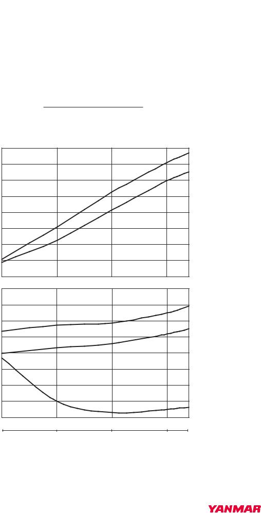
6EY18(A)LW |
|
46623 |
Outline |
No. |
Page |
Engine Performance |
01-03-00 |
1/26 |
|
|
|
1. Model 6EY18ALW (for 60 Hz Generator)
1.1 800 kW/900 min-1
Engine Model: 6EY18ALW
|
|
No. of Cylinders - Bore × Stroke 6 - 180×280 mm |
|
|
|
||||
|
|
Continuous Rating Power 800 kW |
|
|
|
|
|
||
|
|
Engine Speed 900 min-1 |
|
|
|
|
|||
|
|
0.40 |
|
|
|
|
|
|
|
|
|
0.35 |
|
|
|
|
|
|
|
Pa2 (MPa) |
Peg (MPa) |
0.30 |
|
|
|
|
|
|
|
0.25 |
|
|
|
|
|
|
|
||
: : |
|
Pa2 |
|
|
|
|
|
||
|
|
|
|
|
|
|
|||
|
Exh.Gas Press. |
|
|
|
|
|
|
|
|
Boost Press. |
0.20 |
|
|
|
|
|
|
|
|
0.15 |
|
Peg |
|
|
|
|
|
||
|
|
|
|
|
|
|
|||
0.10 |
|
|
|
|
|
|
|
||
|
|
|
|
|
|
|
|
|
|
|
|
0.05 |
|
|
|
|
|
|
|
|
|
0.00 |
|
|
|
|
|
|
|
|
|
270 |
|
|
|
|
|
(°C) |
(°C) |
|
|
|
|
|
|
|
|
||
Specific Fuel Consumption : f (g/kW h) |
260 |
|
|
|
600 |
Exh.Gas Temp. (Cyl.Head outlet) : Tmex |
Exh.Gas Temp. (Turbine inlet) : Tmeg |
||
250 |
|
Tmeg |
|
500 |
|||||
|
|
|
|||||||
240 |
|
Tmex |
|
400 |
|||||
|
|
|
|
|
|||||
230 |
|
|
|
300 |
|||||
220 |
|
|
|
200 |
|||||
210 |
|
|
|
100 |
|||||
200 |
|
f |
|
0 |
|
||||
|
|
|
|
|
|
|
|
||
|
|
190 |
|
|
|
|
|
|
|
|
|
25 |
50 |
75 |
100 |
110 |
Load (%) |
||
|
|
200 |
400 |
600 |
800 |
880 |
Power (kW) |
||
Note: |
|
|
|
|
|
|
|
|
|
Lower Calorific Value |
42.7 MJ/kg |
|
|
|
|
|
|
||
Fuel Consumption at the Engine Shaft End (allowance +5%)
With driven Pump (LOP×1,CWP×2) |
DWG. No. |
G2-46623-1470 |
|
|
|
|
|
|
041285-00E00 |
||
|
|
|
|

6EY18(A)LW |
|
46623 |
Outline |
No. |
Page |
Engine Performance |
01-03-00 |
2/26 |
|
|
|
1.2 745 kW/900 min-1
Engine Model: 6EY18ALW
|
|
No. of Cylinders - Bore × Stroke 6 - 180×280 mm |
|
|
|
||||
|
|
Continuous Rating Power 745 kW |
|
|
|
|
|
||
|
|
Engine Speed 900 min-1 |
|
|
|
|
|||
|
|
0.40 |
|
|
|
|
|
|
|
|
|
0.35 |
|
|
|
|
|
|
|
Pa2 (MPa) |
Peg (MPa) |
0.30 |
|
|
|
|
|
|
|
0.25 |
|
|
|
|
|
|
|
||
: : |
|
|
|
|
|
|
|
||
|
Exh.Gas Press. |
|
|
Pa2 |
|
|
|
|
|
Boost Press. |
0.20 |
|
|
|
|
|
|
|
|
0.15 |
|
Peg |
|
|
|
|
|
||
|
|
|
|
|
|
|
|||
0.10 |
|
|
|
|
|
|
|
||
|
|
|
|
|
|
|
|
|
|
|
|
0.05 |
|
|
|
|
|
|
|
|
|
0.00 |
|
|
|
|
|
|
|
|
|
270 |
|
|
|
|
|
(°C) |
(°C) |
|
|
|
|
|
|
|
|
||
Specific Fuel Consumption : f (g/kW h) |
260 |
|
|
|
600 |
Exh.Gas Temp. (Cyl.Head outlet) : Tmex |
Exh.Gas Temp. (Turbine inlet) : Tmeg |
||
250 |
|
Tmeg |
|
500 |
|||||
|
|
|
|||||||
240 |
|
Tmex |
|
400 |
|||||
|
|
|
|
|
|||||
230 |
|
|
|
300 |
|||||
220 |
|
|
|
200 |
|||||
210 |
|
|
|
100 |
|||||
200 |
|
f |
|
0 |
|
||||
|
|
|
|
||||||
|
|
|
|
|
|
|
|
||
|
|
190 |
|
|
|
|
|
|
|
|
|
25 |
50 |
75 |
100 |
110 |
Load (%) |
||
|
|
186 |
373 |
559 |
745 |
820 |
Power (kW) |
||
Note: |
|
|
|
|
|
|
|
|
|
Lower Calorific Value |
42.7 MJ/kg |
|
|
|
|
|
|
||
Fuel Consumption at the Engine Shaft End (allowance +5%)
With driven Pump (LOP×1,CWP×2) |
DWG. No. |
G2-46623-1460 |
|
|
|
|
|
|
041284-00E00 |
||
|
|
|
|
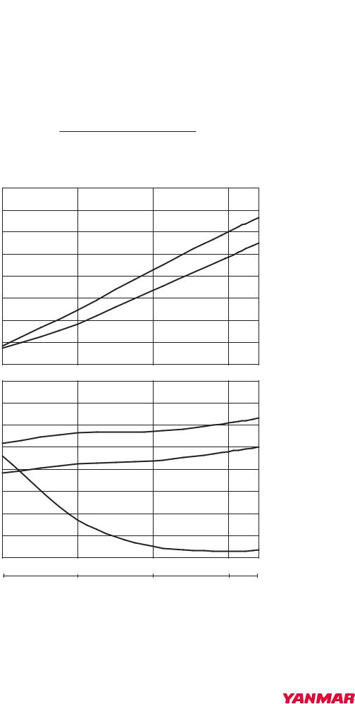
6EY18(A)LW |
|
46623 |
Outline |
No. |
Page |
Engine Performance |
01-03-00 |
3/26 |
|
|
|
1.3 680 kW/900 min-1
Engine Model: 6EY18ALW
|
|
No. of Cylinders - Bore × Stroke 6 - 180×280 mm |
|
|
|
||||
|
|
Continuous Rating Power 680 kW |
|
|
|
|
|
||
|
|
Engine Speed 900 min-1 |
|
|
|
|
|||
|
|
0.40 |
|
|
|
|
|
|
|
|
|
0.35 |
|
|
|
|
|
|
|
Pa2 (MPa) |
Peg (MPa) |
0.30 |
|
|
|
|
|
|
|
0.25 |
|
|
|
|
|
|
|
||
: : |
|
|
|
|
|
|
|
||
Boost Press. |
Exh.Gas Press. |
|
|
Pa2 |
|
|
|
|
|
0.20 |
|
|
|
|
|
|
|
||
0.15 |
|
|
|
|
|
|
|
||
|
|
Peg |
|
|
|
|
|
||
0.10 |
|
|
|
|
|
|
|
||
|
|
|
|
|
|
|
|
|
|
|
|
0.05 |
|
|
|
|
|
|
|
|
|
0.00 |
|
|
|
|
|
|
|
|
|
270 |
|
|
|
|
|
(°C) |
(°C) |
|
|
|
|
|
|
|
|
||
Specific Fuel Consumption : f (g/kW h) |
260 |
|
|
|
600 |
Exh.Gas Temp. (Cyl.Head outlet) : Tmex |
Exh.Gas Temp. (Turbine inlet) : Tmeg |
||
250 |
|
Tmeg |
|
500 |
|||||
|
|
|
|||||||
240 |
|
Tmex |
|
400 |
|||||
|
|
|
|
|
|||||
230 |
|
|
|
300 |
|||||
220 |
|
|
|
200 |
|||||
210 |
|
|
|
100 |
|||||
200 |
|
f |
|
0 |
|
||||
|
|
|
|
||||||
|
|
|
|
|
|
|
|
||
|
|
190 |
|
|
|
|
|
|
|
|
|
25 |
50 |
75 |
100 |
110 |
Load (%) |
||
|
|
170 |
340 |
510 |
680 |
748 |
Power (kW) |
||
Note: |
|
|
|
|
|
|
|
|
|
Lower Calorific Value |
42.7 MJ/kg |
|
|
|
|
|
|
||
Fuel Consumption at the Engine Shaft End (allowance +5%)
With driven Pump (LOP×1,CWP×2) |
DWG. No. |
G2-46623-1450 |
|
|
|
|
|
|
041283-00E00 |
||
|
|
|
|
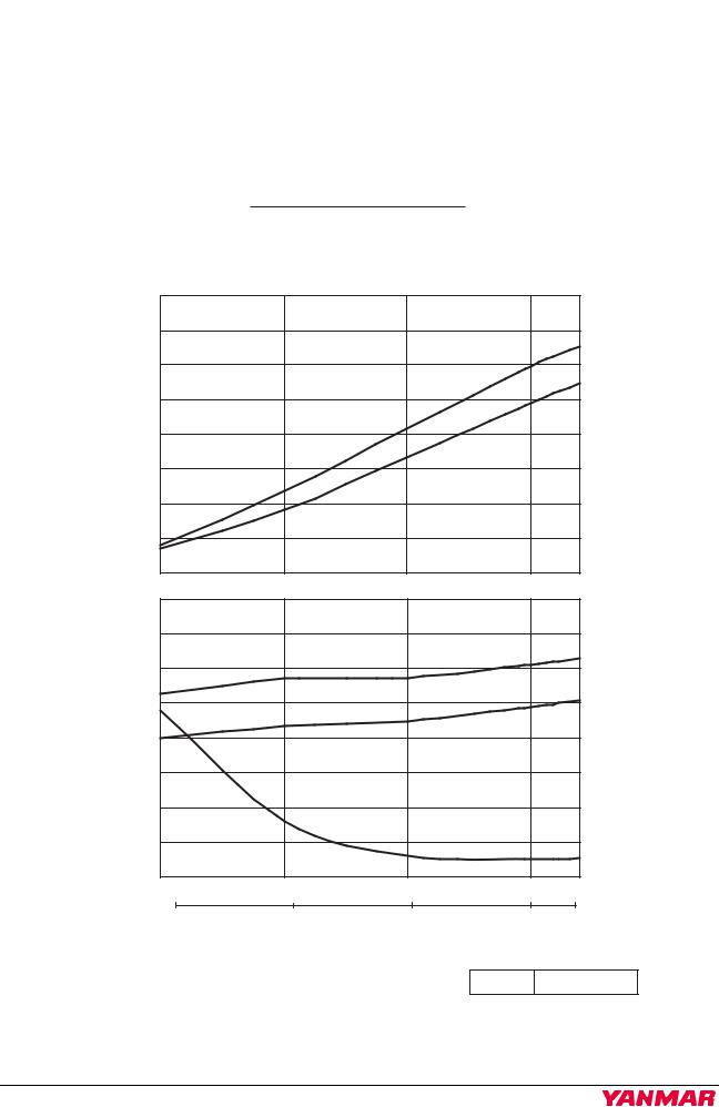
6EY18(A)LW |
|
46623 |
Outline |
No. |
Page |
Engine Performance |
01-03-00 |
4/26 |
|
|
|
1.4 660 kW/900 min-1
Engine Model: 6EY18ALW
|
|
No. of Cylinders - Bore × Stroke 6 - 180×280 mm |
|
|
|
|||
|
|
Continuous Rating Power 660 kW |
|
|
|
|||
|
|
Engine Speed 900 min-1 |
|
|
|
|||
|
|
0.40 |
|
|
|
|
|
|
|
|
0.35 |
|
|
|
|
|
|
Pa2 (MPa) |
Peg (MPa) |
0.30 |
|
|
|
|
|
|
0.25 |
|
|
|
|
|
|
||
: : |
|
|
|
|
|
|
||
Boost Press. |
Exh.Gas Press. |
0.20 |
|
Pa2 |
|
|
|
|
|
|
|
|
|
|
|||
0.15 |
|
|
|
|
|
|
||
0.10 |
|
Peg |
|
|
|
|
||
|
|
|
|
|
|
|
|
|
|
|
0.05 |
|
|
|
|
|
|
|
|
0.00 |
|
|
|
|
|
|
|
|
270 |
|
|
|
|
(°C) |
(°C) |
|
|
|
|
|
|
|
||
Specific Fuel Consumption : f (g/kW h) |
260 |
|
|
|
600 |
Exh.Gas Temp. (Cyl.Head outlet) : Tmex |
Exh.Gas Temp. (Turbine inlet) : Tmeg |
|
250 |
|
|
Tmeg |
500 |
||||
|
|
|
||||||
240 |
|
|
Tmex |
400 |
||||
|
|
|
||||||
230 |
|
|
|
300 |
||||
220 |
|
|
|
200 |
||||
210 |
|
|
|
100 |
||||
|
|
f |
|
|
||||
200 |
|
|
|
0 |
||||
|
|
|
|
|
|
|
||
|
|
190 |
|
|
|
|
|
|
|
|
25 |
50 |
75 |
100 |
110 Load (%) |
||
|
|
165 |
330 |
495 |
660 |
726 Power (kW) |
||
Note: |
|
|
|
|
|
|
|
|
Lower Calorific Value 42.7 MJ/kg
Fuel Consumption at the Engine Shaft End (allowance +5%)With driven Pump (LOP×1,CWP×2)
DWG. No. G2-46623-1440
041282-00E00
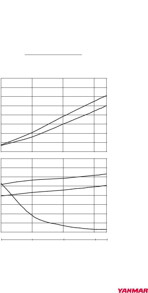
6EY18(A)LW |
|
46623 |
Outline |
No. |
Page |
Engine Performance |
01-03-00 |
5/26 |
|
|
|
1.5 615 kW/900 min-1
Engine Model: 6EY18ALW
|
|
No. of Cylinders - Bore × Stroke 6 - 180×280 mm |
|
|
|
||||
|
|
Continuous Rating Power 615 kW |
|
|
|
|
|
||
|
|
Engine Speed 900 min-1 |
|
|
|
|
|||
|
|
0.40 |
|
|
|
|
|
|
|
|
|
0.35 |
|
|
|
|
|
|
|
Pa2 (MPa) |
Peg (MPa) |
0.30 |
|
|
|
|
|
|
|
0.25 |
|
|
|
|
|
|
|
||
: : |
|
|
|
|
|
|
|
||
Boost Press. |
Exh.Gas Press. |
0.20 |
|
Pa2 |
|
|
|
|
|
|
|
|
|
|
|
|
|||
0.15 |
|
|
|
|
|
|
|
||
0.10 |
|
Peg |
|
|
|
|
|
||
|
|
|
|
|
|
|
|
||
|
|
|
|
|
|
|
|
|
|
|
|
0.05 |
|
|
|
|
|
|
|
|
|
0.00 |
|
|
|
|
|
|
|
|
|
270 |
|
|
|
|
|
(°C) |
(°C) |
|
|
|
|
|
|
|
|
||
Specific Fuel Consumption : f (g/kW h) |
260 |
|
|
|
600 |
Exh.Gas Temp. (Cyl.Head outlet): Tmex |
Exh.Gas Temp. (Turbine inlet) : Tmeg |
||
250 |
|
|
|
500 |
|||||
Tmeg |
|
|
|
|
|||||
240 |
|
|
|
400 |
|||||
|
Tmex |
|
|
|
|
||||
230 |
|
|
|
300 |
|||||
220 |
|
|
|
200 |
|||||
210 |
|
f |
|
100 |
|||||
|
|
|
|
|
|||||
200 |
|
|
|
0 |
|
||||
|
|
|
|
|
|
|
|
||
|
|
190 |
|
|
|
|
|
|
|
|
|
25 |
50 |
75 |
100 |
110 |
Load (%) |
||
|
|
154 |
308 |
461 |
615 |
677 |
Power (kW) |
||
Note: |
|
|
|
|
|
|
|
|
|
Lower Calorific Value |
42.7 MJ/kg |
|
|
|
|
|
|
||
Fuel Consumption at the Engine Shaft End (allowance +5%)
With driven Pump (LOP×1,CWP×2) |
DWG. No. |
G2-46623-1430 |
|
|
|
|
|
|
041281-00E00 |
||
|
|
|
|
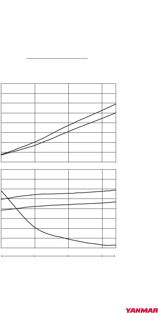
6EY18(A)LW |
|
46623 |
Outline |
No. |
Page |
Engine Performance |
01-03-00 |
6/26 |
|
|
|
1.6 550 kW/900 min-1
Engine Model: 6EY18ALW
|
|
No. of Cylinders - Bore × Stroke 6 - 180×280 mm |
|
|
|
||||
|
|
Continuous Rating Power 550 kW |
|
|
|
|
|
||
|
|
Engine Speed 900 min-1 |
|
|
|
|
|||
|
|
0.40 |
|
|
|
|
|
|
|
|
|
0.35 |
|
|
|
|
|
|
|
Pa2 (MPa) |
Peg (MPa) |
0.30 |
|
|
|
|
|
|
|
0.25 |
|
|
|
|
|
|
|
||
: : |
|
|
|
|
|
|
|
||
Boost Press. |
Exh.Gas Press. |
0.20 |
|
|
|
|
|
|
|
|
|
Pa2 |
|
|
|
|
|
||
0.15 |
|
|
|
|
|
|
|
||
0.10 |
|
Peg |
|
|
|
|
|
||
|
|
|
|
|
|
|
|
||
|
|
|
|
|
|
|
|
|
|
|
|
0.05 |
|
|
|
|
|
|
|
|
|
0.00 |
|
|
|
|
|
|
|
|
|
270 |
|
|
|
|
|
(°C) |
(°C) |
|
|
|
|
|
|
|
|
||
Specific Fuel Consumption : f (g/kW h) |
260 |
|
|
|
600 |
Exh.Gas Temp. (Cyl.Head outlet) : Tmex |
Exh.Gas Temp. (Turbine inlet) : Tmeg |
||
250 |
Tmeg |
|
|
500 |
|||||
|
|
|
|
|
|||||
240 |
|
|
|
400 |
|||||
|
Tmex |
|
|
|
|
||||
230 |
|
|
|
300 |
|||||
220 |
|
|
|
200 |
|||||
210 |
|
f |
|
100 |
|||||
|
|
|
|
|
|||||
200 |
|
|
|
0 |
|
||||
|
|
|
|
|
|
|
|
||
|
|
190 |
|
|
|
|
|
|
|
|
|
25 |
50 |
75 |
100 |
110 |
Load (%) |
||
|
|
138 |
275 |
413 |
550 |
605 |
Power (kW) |
||
Note: |
|
|
|
|
|
|
|
|
|
Lower Calorific Value |
42.7 MJ/kg |
|
|
|
|
|
|
||
Fuel Consumption at the Engine Shaft End (allowance +5%)
With driven Pump (LOP×1,CWP×2) |
DWG. No. |
G2-46623-1421 |
|
|
|
|
|
|
041280-00E00 |
||
|
|
|
|
Loading...