


3TNV82A
Table of contents
 Loading...
TROUBLESHOOTING
Gehl Form No. 50950006, AP1210
MANUAL
ELECTRONIC CONTROL
3TNV82A
3TNV82A-B
3TNV84
3TNV84T
3TNV84T-B
3TNV88
3TNV88-B
3TNV88-U
4TNV84
4TNV84T
4TNV84T-Z
4TNV88
4TNV88-B
4TNV88-U
4TNV94L
4TNV98
4TNV98-Z
4TNV98-E
4TNV98T
4TNV98T-Z
4TNV106
4TNV106T

California
Proposition 65 Warning
California
Proposition 65 Warning
Diesel engine exhaust and some of its
constituents are known to the state of
California to cause cancer, birth
defects, and other reproductive harm.
Battery posts, terminals, and related
accessories contain lead and lead
compounds, chemicals known to the
state of California to cause cancer and
reproductive harm.
Wash hands after handling.

TNV DI Service Manual
Section 1
FAILURE DIAGNOSIS
Page
DTCs (Diagnostic Trouble Codes) General Description.................. 1-3
DTC Code List........................................................................... 1-3
Description Items....................................................................... 1-7
Analog Input Related Failures................................................... 1-8
Pulse Sensor Related Failures................................................ 1-60
Contact Output Related Failures............................................. 1-66
Contact Input Related Failures.............................................. 1-100
Actuators etc.......................................................................... 1-114
E-ECU Internal and Communication Errors........................... 1-122
Method and Procedure of Failure Diagnosis............................... 1-133
Description Items................................................................... 1-133
Analog Input Related Failures............................................... 1-136
Pulse Sensor Related Failures.............................................. 1-164
Contact Output Related Failures........................................... 1-170
Contact Input Related Failures.............................................. 1-187
Actuator Related Failures...................................................... 1-193
ECU Internal and Communication Errors.............................. 1-197
FAILURE INDICATOR LAMP FLASHING PATTERN........... 1-207
Using the Failure Indicator for Failure Diagnosis ........................ 1-208
Flashing Patterns of the Failure Indicator.............................. 1-208
Factor Analysis............................................................................ 1-210
2G-Type Eco-Governor Speed-Fluctuation Factor Analysis. 1-210
2G-Type Eco-Governor Engine
Stalling/Start-Up Inability Factor Analysis.............................. 1-213
2G-Type Eco-Governor Black Smoke Factor Analysis.......... 1-216
Special Service Tools.................................................................. 1-218
Troubleshooting By Measuring Compression Pressure.............. 1-219
Compression Pressure Measurement Method...................... 1-219
Quick Reference Table For Troubleshooting .............................. 1-222
TNV DI Service Manual
1-1

FAILURE DIAGNOSIS
This Page Intentionally Left Blank
1-2
TNV DI Service Manual
DTCs (Diagnostic Trouble Codes) General Description
FAILURE DIAGNOSIS
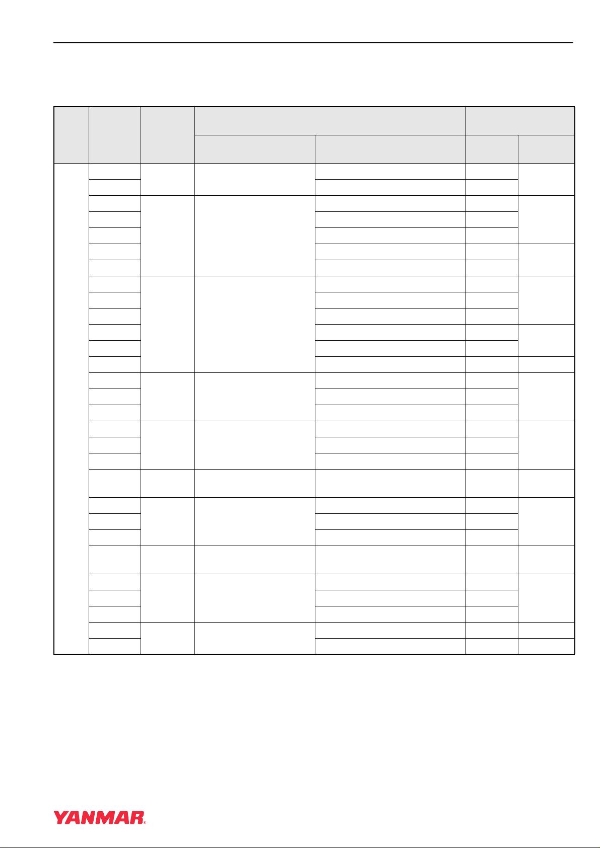
DTCS (DIAGNOSTIC TROUBLE CODES) GENERAL DESCRIPTION
DTC Code List
Clas
sifica
tion
Analog Input Related Failures
DTC
P1202/4
P1203/3 Error (high voltage) P.1-10
P0122/4
P0124/2 Intermittent failure P.1-16
P1125/1 Error (foot pedal-close position) P.1-18
P1126/0 Error (foot pedal-open position) P.1-20
P0222/4
P0224/2 Intermittent failure P.1-26
P1225/1 Error (foot pedal-close position) P.1-28
P1226/0 Error (foot pedal-open position) P.1-30
P1227/8 Error (pulse communication) P.1-32 P.1-152
P0222/4
P0224/2 Intermittent failure P.1-38
P0668/4
P1644/2 Intermittent failure P.1-42
P0634/0 2-5
P0117/4
P0119/2 Intermittent failure P.1-49
P0217/0 3-6
P0642/4
P1644/2 Intermittent failure P.1-55
P0562/1
P0563/0 Error (High Voltage) P.1-58 P.1-58
Lamp
Flashing
Patterns
Area Status Overview
7 Rack position sensor
5 Accelerator sensor
1-8 Spare accelerator sensor
1-9
4-1
4
2-4 SENSOR 5V
2-3 Power supply Voltage
Atmospheric pressure
sensor
ECU Temperature
Sensor
ECU Temperature Rise
Alarm
Cooling water
temperature sensor
Cooling Water
Temperature Rise Alarm
Error Item
Error (low voltage) P.1-8
Error (low voltage) P.1-12
Error (low voltage) P.1-22
Error (low voltage) P.1-34
Error (low voltage) P.1-40
Error (Low Voltage) P.1-45
Error (low voltage) P.1-53
Error (Low Voltage) P.1-56 P.1-56
Referenced page
number
Diagnosis
P.1-43 P.1-154
P.1-51 P.1-156
Failure
P.1-136
P.1-140P1203/3 Error (high voltage) P.1-14
P.1-144
P.1-148P0223/3 Error (high voltage) P.1-24
P.1-144
P.1-148P0223/3 Error (high voltage) P.1-36
P.1-154P0669/3 Error (high voltage) P.1-41
P.1-156P0118/3 Error (High Voltage) P.1-47
P.1-160P0643/3 Error (High Voltage) P.1-54
TNV DI Service Manual
1-3
FAILURE DIAGNOSIS
DTCs (Diagnostic Trouble Codes) General Description
Clas
sifica
tion
Pulse Sensors
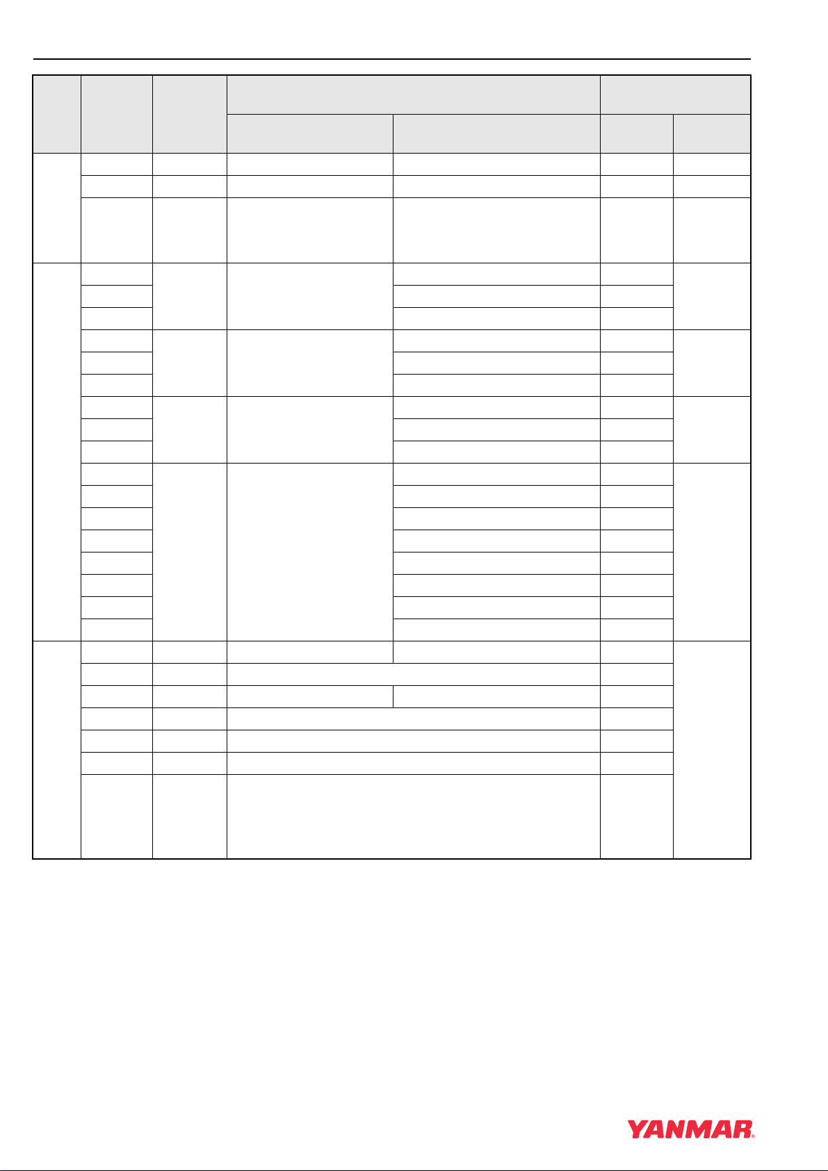
Contact Output Related Failures
Lamp
DTC
P0340/4 6 Speed Sensor Error P.1-60 P.1-164
P1340/4 1-1 Spare speed sensor Error P.1-62 P.1-167
P0219/0 9 Overspeed Error P.1-64 P.1-64
P1222/4
P1224/2 Intermittent failure P.1-70
P1232/4
P1234/2 Intermittent failure P.1-76
P1242/4
P1244/2 Intermittent failure P.1-82
P1402/4
P1403/3 Error B (Step Motor A-Phase) P.1-86
P1412/4 Error A (Step Motor B-Phase) P.1-88
P1413/3 Error B (Step Motor B-Phase) P.1-90
P1422/4 Error A (Step Motor C-Phase) P.1-92
P1423/3 Error B (Step Motor C-Phase) P.1-94
P1432/4 Error A (Step Motor D-Phase) P.1-96
P1433/3 Error B (Step Motor D-Phase) P.1-98
P1192/4 2-1 Oil pressure switch Error P.1-100
P1198/1 3-1 Oil Pressure Descend Error P.1-102
P1562/4 2-2 Charge switch Error P.1-104
P1568/1 3-2 Charge Alarm P.1-106
P1217/0 3-3 Abnormal Water Temperature P.1-108
P1101/0 3-4 Air cleaner Clogging Alarm P.1-110
Flashing
Patterns
1-7 Rack actuator Relay
1-5 Start Assist Relay
1-4 CSD solenoid valve
1-3 EGR valve
Area Status Overview
Error Item
Error A P.1-66
Error A P.1-72
Error A P.1-78
Error A (Step Motor A-Phase) P.1-84
Referenced page
number
Failure
Diagnosis
P.1-170P1223/3 Error B P.1-68
P.1-174P1233/3 Error B P.1-74
P.1-178P1243/3 Error B P.1-80
P.1-182
P.1-187
Contact Input Related Failures
1-4
P1151/0 3-5 Oil-water separator Alarm P.1-112
TNV DI Service Manual
DTCs (Diagnostic Trouble Codes) General Description
FAILURE DIAGNOSIS
Clas
sifica
tion
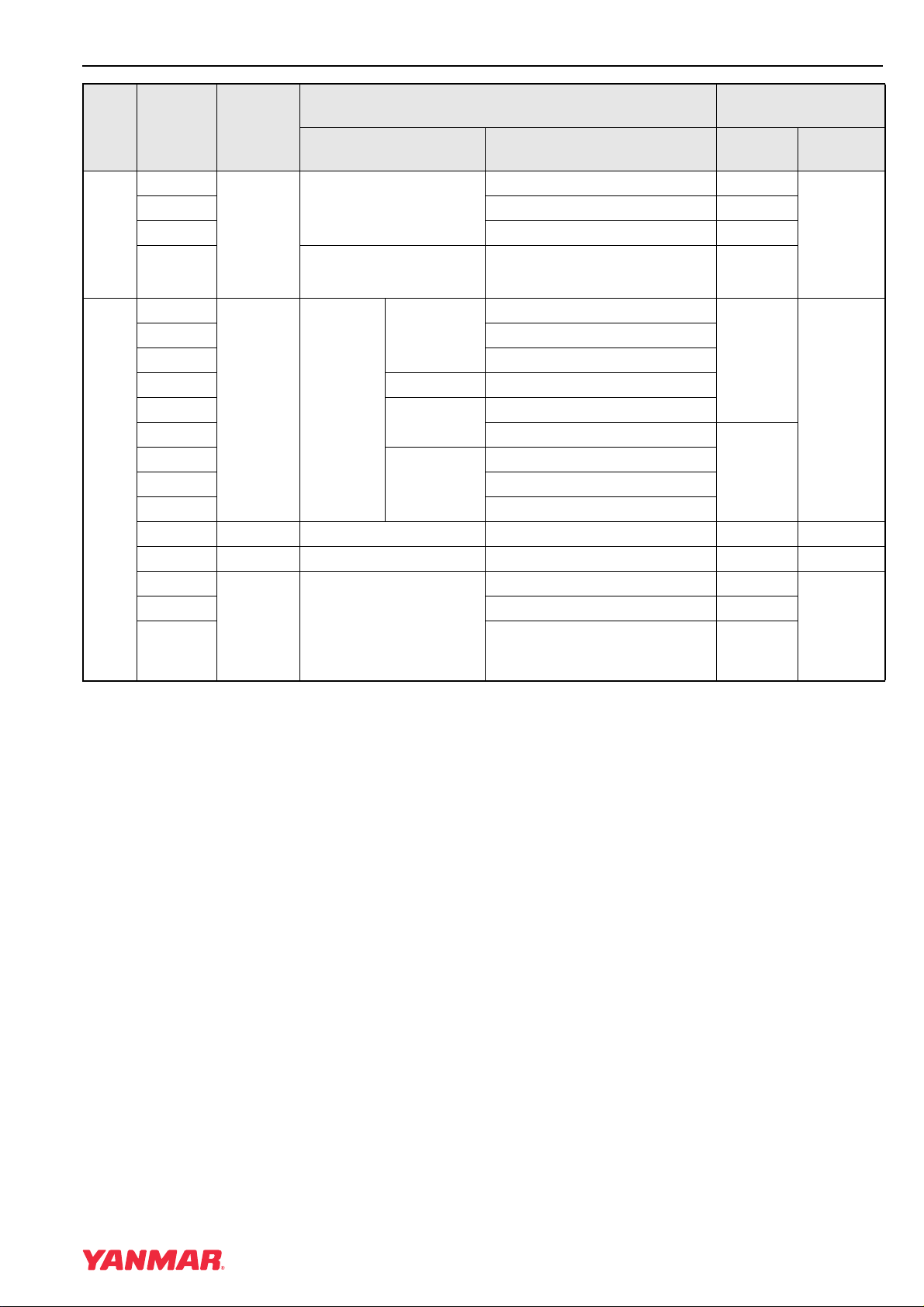
DTC
P1212/4
P1213/3 Error (high current) P.1-116
P1211/7 Mechanical failure P.1-118
P1214/2 Engine Error P.1-120
Actuator Errors
P0605/12
P1605/2 Error (Checksum B)
P1606/2 Error (Checksum C)
P1620/12 Map format Error
P1601/2
P0601/12 Error (read/write error)
P1610/12
P1611/12 Error B
P1612/12 Error C
P0686/4 1-6 Main relay Error P.1-124 P.1-199
U0001/12 1-2 CAN Communication Error P.1-126 P.1-203
U0167/12
U1167/8 Error (pulse communication) P.1-130
U0426/2 Error (System) P.1-132
ECU inside and Communication Related Failures
Lamp
Flashing
Patterns
Rack actuator
8
4-1
4-2 Immobilizer
ECU
Internal
Error Item
Area Status Overview
Error (low current) P.1-114
Error (Checksum A)
Flash ROM
EEPROM
Sub CPU
Error (Checksum)
Error A
Error (CAN communication) P.1-128
Referenced page
number
P.1-122
P.1-123
Failure
Diagnosis
P.1-193
P.1-197
P.1-205
TNV DI Service Manual
1-5

FAILURE DIAGNOSIS
DTCs (Diagnostic Trouble Codes) General Description
This Page Intentionally Left Blank
1-6
TNV DI Service Manual

DTCs (Diagnostic Trouble Codes) General Description
Description Items
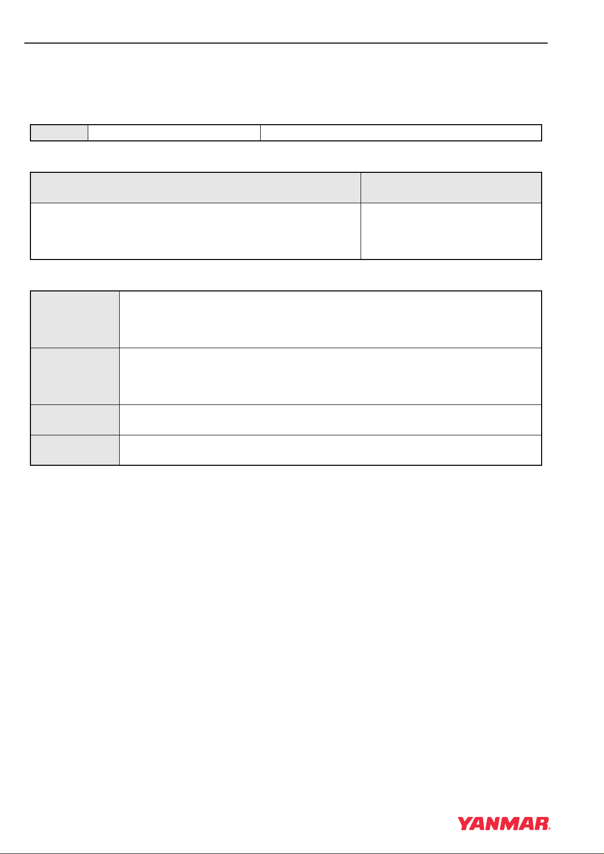
DTC Code Number DTC Name
DTC Detecting Conditions
FAILURE DIAGNOSIS
1 - Precondition; 2 - Detecting condition(s);
3 - Flashing pattern of failure indicator
1. Precondition for Error detection
2. Error detecting Condition
3. Indicates the pattern in which the failure lamp flashes when the
DTC is output. (For detailed information on various flashing
patterns, see Annex).
This column shows what parts or
items should be checked to identify
the cause of the error.
For details, see "<Diagnosis
Description>."
Check points
Movement at Error occurrence
Error Mode [Operation Continuation] / [Run Under Restrictions] / [Stop Immediately]:
The engine operation after detecting the error is described.
*
[Operation Continuation]:After detecting the error, the system lets the engine
continue to run without any restrictions.
[Run Under Restrictions]:The system lets the engine continue to run but restricts the
High idle speed, engine power, and/or other performance
factors as appropriate.
[Stop Immediately]: The system stops the engine immediately after detecting the
error.When any error is detected before starting the engine, the
starter will not rotate.
Run restricted? Yes/No.: If Yes, this field details how the engine run is restricted when the error has
occurred.
Recovery
Conditions
Yes/No.: If Yes, this field describes what conditions must be true for the error mode
to be reset.
Remarks This field describes some notes on safety precautions and so on, as appropriate.
Estimation of Failure cause/Error condition
Provides descriptive information on possible points of failure, possible direct causes (such as a disconnected sensor
wire), or possible system abnormalities that has indirectly caused the failure (such as abnormally high cooling water
temperature), as can be estimated from the output DTC.
Note: Indicates failures that might be related with the output DTC.
Diagnosis Description
Describes methods or procedures of failure d iagnosis.
* After sucessful recovery by the replaceme nt of ECU, sensor or actuato r , make sure that installing
the previous parts will reproduce the same error.
TNV DI Service Manual
1-7
FAILURE DIAGNOSIS
DTCs (Diagnostic Trouble Codes) General Description
Analog Input Related Failures
Rack position sensor
(1) P1202/4: Failure with Rack Position Sensor (Low Voltage)
DTC P1202/4 Rack Position Sensor Error (Low Voltage)
DTC Detecting Conditions
1 - Precondition; 2 - Detecting condition(s);
3 - Flashing pattern of failure indicator
1. Key switch ON.
2. The sensor voltage lower limit and below [at E-ECU activation,
engine running]
3. Seven flashes.
Connector
Harness
Rack position sensor
E-ECU
Check points
Movement at Error occurrence
Error Mode [Run Under Restrictions]:
The engine continues to run in on-error engine control mode.
If any error is detected at E-ECU activation, it takes 1 - 10 seconds from the starter
begins to rotate until the engine starts.
Run restricted? Yes: • The High idle speed is restricted to one of the following, whichever smaller:
• 80% of the pre-error High idle speed
• 150% of the Low idle speed
• The fuel injection rate is restricted.
Recovery
No.
Conditions
Remarks The High and Low idle speeds must be equal to those specified in the engine
specifications.
Estimation of Failure cause/Error condition
• The connector may not be properly connected.
• Wiring defect of the harness
• The rack position sensor's signal wires ma y be disconnected or short-circuited with GND .
• The SENSOR 12V wire may be disconnected or short-circuited with GND (*NOTE).
• The SENSOR GND wire may be short-circuited with POWER SUPPLY (*NOTE).
*NOTE) If the SENSOR 12V wire is short-circuited wi th GND or SE NSOR GND wire is shor t-circuited with
POWER SUPPLY, the E-ECU's po wer supply line fuse 10A might be blo wn.With this fuse b lown, the
E-ECU may fail to detect/ind icate the error, and to store the error history .
The rack position sensor may be faulty.
• Output defect of the r ack position signal by a disconnection or a short circuit of the inner wiring
• The E-ECU internal circuitry may be faulty.
1-8
TNV DI Service Manual

DTCs (Diagnostic Trouble Codes) General Description
Diagnosis Description
FAILURE DIAGNOSIS
1) Initial diagnosis
with the diagnosis
tool
2) Check of
connectors/wiring
3) Failure Diagnostic
Work
• Check the fault indication.
• Check the sensor voltage (AD value).
*For details of the method and the procedure of diagnosis, see P.1-136
• Before beginning your work, be sure to turn off the key switch.
• Check that the connector of the rack actuator is correctly inserted.
• Check that the wiring of the rack actuator is not disconnected or the insulation
of the wiring is not peeled.
• Check the input voltage of the rack position sensor (voltage of the sensor 12V
line).
• Check the harness for correct continuity.
*For details of the method and the procedure of diagnosis, see P.1-136
TNV DI Service Manual
1-9

FAILURE DIAGNOSIS
DTCs (Diagnostic Trouble Codes) General Description
(2) P1203/3: Failure with Rack Position Sensor (High Voltage)
DTC P1202/3 Failure with Rack Position Sensor (High Voltage)
DTC Detecting Conditions
1 - Precondition; 2 - Detecting condition(s);
3 - Flashing pattern of failure indicator
1. Key switch ON.
2. The sensor voltage upper limit and above [at E-ECU activation,
engine running]
3. Seven flashes.
Movement at Error occurrence
Detection at the engine start Detection at the engine running
Error Mode [Run Under Restrictions]:
Start the engine in on-error engine control
mode.
It takes 1 to 10 seconds from the starter’s
rotation to the engine start.
Run restricted? Yes: • The High idle is restricted to one of
the following, whichever smaller:
• 80% of the pre-error High idle speed
• 150% of the Low idle speed
• The fuel injection rate is restricted.
Recovery
No. No.
Conditions
Remarks The High and Low idle speeds must be
equal to those specified in the engine
specifications.
Check points
Connector
Harness rack position sensor
Rack actuator
E-ECU
[Stop Immediately]:
The engine stops running.
Yes: The rack actuator relay is turned
OFF, and the rack position is forcibly
set to the engine stop position.
Estimation of Failure cause/Error condition
• The connector may not be properly connected.
• Wiring defect of the harness
• The SENSOR GND wire may be disconnected.
• The rack position sensor signal wire ma y be short-circuited with POWER SUPPLY .
• The rack actuator wiring ma y be short-circuited with GND (with engine running).
• The rack position sensor may be faulty.
• Output defect of the r ack position signal by a disconnection or a short circuit of the inner wiring
• The rack actuator may be faulty.
• The rack actuator inner wiring ma y be short-circuited with GND (with engine running).
• The E-ECU internal circuitry may be faulty.
1-10
TNV DI Service Manual

DTCs (Diagnostic Trouble Codes) General Description
Diagnosis Description
FAILURE DIAGNOSIS
1) Initial diagnosis
with the diagnosis
tool
2) Check of
connectors/wiring
3) Failure Diagnostic
Work
• Check the fault indication.
• Check the sensor voltage (AD value).
*For details of the method and the procedure of diagnosis, see P.1-136
• Before beginning your work, be sure to turn off the key switch.
• Check that the connector of the rack actuator is correctly inserted.
• Check that the wiring of the rack actuator is not disconnected or the insulation
of the wiring is not peeled.
• Check the input voltage of the rack position sensor (voltage of the sensor 12V
line).
• Check the harness for correct continuity.
*For details of the method and the procedure of diagnosis, see P.1-136
TNV DI Service Manual
1-11
FAILURE DIAGNOSIS
DTCs (Diagnostic Trouble Codes) General Description
Accelerator sensor
(1) P0122/4: Accelerator Sensor Error (Low Voltage)
DTC P0122/4 Accelerator Sensor Error (Low Voltage)
DTC Detecting Conditions
1 - Precondition; 2 - Detecting condition(s);
3 - Flashing pattern of failure indicator
1. Key switch ON.
2. Sensor voltage 0.2 [V] or lower.
3. Five flashes.
Movement at Error occurrence
Spare Accelerator Sensor Function
Unavailable Available
Error Mode [Run Under Restrictions]:
The engine runs at a constant rotational
speed.
Run restricted? Yes: The target speed is set to the "on-
error target speed (standard value:
1500[min
-1
])" or “pre-error target
speed”.
Recovery
Conditions
Yes: This error will be automatically reset
when a normal voltage (0.2 to
4.6[V]) is input.
Remarks
Check points
Harness
Accelerator sensor
[Stop Immediately]:
The engine continues to run using the
spare accelerator sensor instead.
No.
Yes: This error will be automatically reset
when a normal voltage (0.2 to
4.6[V]) is input.
Estimation of Failure cause/Error condition
• The connector may not be properly connected.
• Wiring defect of the harness
• The accelerator sensor's signal wires ma y be disconnected or short-circuited with GND .
• The SENSOR 5V wire may be disconnected o r short-circuited with GND.
• The SENSOR GND wire may be short-circuited with POWER SUPPLY (*NOTE).
*NOTE) If the SENSOR GND wire is short-circuited with PO WER SUPPL Y , the E-ECU's po wer supply line fuse
10A might be blown.With this fuse blown, the E-ECU may fail to detect/indicate the error , and to store
the error history.
• The accelerator sensor may be faulty.
• Sensor output defect by a disconnection of the accelerator sensor inner wiring or a sliding resistance
increase
• The E-ECU internal circuitry may be faulty.
1-12
TNV DI Service Manual
DTCs (Diagnostic Trouble Codes) General Description
Diagnosis Description
FAILURE DIAGNOSIS
1) Initial diagnosis
with the diagnosis
tool
2) Check of
connectors/wiring
3) Failure Diagnostic
Work
• Check the fault indication.
• Check the sensor voltage.
*For details of the method and the procedure of diagnosis, see P.1-140
• Before beginning your work, be sure to turn off the key switch.
• Check that the connector of the accelerator sensor is correctly inserted.
• Check that the wiring of the accelerator sensor is not disconnected or the
insulation of the wiring is not peeled.
• Check the resistance value of the accelerator sensor.
• Check the harness for correct continuity.
• Check the output voltage of the accelerator sensor.
*For details of the method and the procedure of diagnosis, see P.1-140
TNV DI Service Manual
1-13
FAILURE DIAGNOSIS
DTCs (Diagnostic Trouble Codes) General Description
(2) P0123/3: Accelerator Sensor Error (High Voltage)
DTC P0123/3 Accelerator Sensor Error (High Voltage)
DTC Detecting Conditions
1 - Precondition; 2 - Detecting condition(s);
3 - Flashing pattern of failure indicator
1. Key switch ON.
2. Sensor voltage 4.6 [V] or higher.
3. Five flashes.
Movement at Error occurrence
Spare Accelerator Sensor Function
Unavailable Available
Error Mode [Run Under Restrictions]:
The engine runs at a constant rotational
speed.
Run restricted? Yes: The target speed is set to the "on-
error target speed (standard value:
-1
1500[min
])" or “pre-error target
speed”.
Recovery
Conditions
Yes: This error will be automatically reset
when a normal voltage (0.2 to
4.6[V]) is input.
Remarks
Check points
Harness
Accelerator sensor
[Stop Immediately]:
The engine continues to run using the
spare accelerator sensor instead.
No.
Yes: This error will be automatically reset
when a normal voltage (0.2 to
4.6[V]) is input.
Estimation of Failure cause/Error condition
• The connector may not be properly connected.
• Wiring defect of the harness
• The SENSOR GND wire may be disconnected.
• The sensor signal wire may be short-circuited with POWER SUPPLY.
• The accelerator sensor may be faulty.
• Sensor output defect by a short circuit with pow er supply of the accelerator sensor inner wiring
• The E-ECU internal circuitry may be faulty.
1-14
TNV DI Service Manual

DTCs (Diagnostic Trouble Codes) General Description
Diagnosis Description
FAILURE DIAGNOSIS
1) Initial diagnosis
with the diagnosis
tool
2) Check of
connectors/wiring
3) Failure Diagnostic
Work
• Check the fault indication.
• Check the sensor voltage.
*For details of the method and the procedure of diagnosis, see P.1-140
• Before beginning your work, be sure to turn off the key switch.
• Check that the connector of the accelerator sensor is correctly inserted.
• Check that the wiring of the accelerator sensor is not disconnected or the
insulation of the wiring is not peeled.
• Check the resistance value of the accelerator sensor.
• Check the harness for correct continuity.
• Check the output voltage of the accelerator sensor.
*For details of the method and the procedure of diagnosis, see P.1-140
TNV DI Service Manual
1-15

FAILURE DIAGNOSIS
DTCs (Diagnostic Trouble Codes) General Description
(3) P0124/2: Intermittent Failure with Accelerator Sensor
DTC P0124/2 Intermittent Failure with Accelerator Sensor
DTC Detecting Conditions
1 - Precondition; 2 - Detecting condition(s);
3 - Flashing pattern of failure indicator
1. Engine running.
2. Unconfirmed error detected 10 times.
3: Does not flash.
Connector
Harness
Accelerator sensor
Check points
Movement at Error occurrence
Error Mode [Run Under Restrictions]:
After detecting the error, the system lets the engine continue to run without any
restrictions.
Run restricted? No.
Recovery
No.
Conditions
Remarks
Estimation of Failure cause/Error condition
• The connector may not be properly connected.
• Wiring defect of the harness
• Accelerator sensor signal wire ma y be disconnected, or short-circuited with GND or power supply.
• Sensor 5V wire may be disconnected, or short-circuited with GND or power supply.
• Sensor GND wire may be disconnected.
• The accelerator sensor may be faulty.
• Inner wiring may be disconnected or short-circuited
1-16
TNV DI Service Manual

DTCs (Diagnostic Trouble Codes) General Description
Diagnosis Description
FAILURE DIAGNOSIS
1) Initial diagnosis
with the diagnosis
tool
2) Check of
connectors/wiring
3) Failure Diagnostic
Work
• Check the fault indication.
• Check the sensor voltage.
*For details of the method and the procedure of diagnosis, see P.1-140
• Before beginning your work, be sure to turn off the key switch.
• Check that the connector of the accelerator sensor is correctly inserted.
• Check that the wiring of the accelerator sensor is not disconnected or the
insulation of the wiring is not peeled.
• Check the resistance value of the accelerator sensor.
• Check the harness for correct continuity.
• Check the output voltage of the accelerator sensor.
*For details of the method and the procedure of diagnosis, see P.1-140
TNV DI Service Manual
1-17

FAILURE DIAGNOSIS
DTCs (Diagnostic Trouble Codes) General Description
(4) P0123/1: Accelerator Sensor Error (foot pedal-close position)
DTC P1125/1 Accelerator Sensor Error (foot pedal-close position)
DTC Detecting Conditions
1 - Precondition; 2 - Detecting condition(s);
3 - Flashing pattern of failure indicator
1. Key switch ON.
2. With sensor voltage at or below 0.65[V], foot pedal Normally
Harness
Foot pedal
Check points
Open switch detected being ON or foot pedal Normally Closed
Switch detected being OFF.
3. Five flashes.
Movement at Error occurrence
Error Mode [Run Under Restrictions]:
The engine runs at a constant rotational speed.
Run restricted? Yes: The target speed is set to the "on-error target speed (standard value: 1500[min-1])"
or “pre-error target speed”.
Recovery
No.
Conditions
Remarks
Estimation of Failure cause/Error condition
• The connector may not be properly connected.
• Wiring defect of the harness
• The wiring for the f oot pedal Normally Closed switch ma y be disconnected.
• The wiring for the f oot pedal Normally Open switch ma y be short-circuited with GND .
• The foot pedal may be faulty.
• The foot pedal inner wiring ma y be disconnected or short-circuited with GND .
• The E-ECU internal circuitry may be faulty.
1-18
TNV DI Service Manual
DTCs (Diagnostic Trouble Codes) General Description
Diagnosis Description
FAILURE DIAGNOSIS
1) Initial diagnosis
with the diagnosis
tool
2) Check of
connectors/wiring
3) Failure Diagnostic
Work
• Check the fault indication.
• Check that the foot pedal movement is correctly recognized.
*For details of the method and the procedure of diagnosis, see P.1-144
• Before beginning your work, be sure to turn off the key switch.
• Check that the connector of the foot pedal is correctly inserted.
• Check that the wiring of the foot pedal is not disconnected or the insulation of
the wiring is not peeled.
• Check the foot pedal for correct continuity.
• Check the harness for correct continuity.
*For details of the method and the procedure of diagnosis, see P.1-144
TNV DI Service Manual
1-19
FAILURE DIAGNOSIS
DTCs (Diagnostic Trouble Codes) General Description
(5) P1126/0: Accelerator Sensor Error (foot pedal-open position)
DTC P1126/0 Accelerator Sensor Error (foot pedal-open position)
DTC Detecting Conditions
1 - Precondition; 2 - Detecting condition(s);
3 - Flashing pattern of failure indicator
1. Key switch ON.
2. With sensor voltage 1.1[V] and above, foot pedal Normally Open
Harness
Foot pedal
Check points
switch detected being OFF or foot pedal Normally Closed
Switch detected being ON.
3. Five flashes.
Movement at Error occurrence
Error Mode [Run Under Restrictions]:
The engine runs at a constant rotational speed.
Run restricted? Yes: The target speed is set to the "on-error target speed (standard value: 1500[min-1])"
or “pre-error target speed”.
Recovery
No.
Conditions
Remarks
Estimation of Failure cause/Error condition
• The connector may not be properly connected.
• Wiring defect of the harness
• The wiring for the f oot pedal Normally Open switch ma y be disconnected.
• The wiring for the fo ot pedal Normally Closed switch ma y be short-circuited with GND .
• The foot pedal may be faulty.
• The inner wiring may be disconnected or short-circuited with GND .
• The E-ECU internal circuitry may be faulty.
1-20
TNV DI Service Manual

DTCs (Diagnostic Trouble Codes) General Description
Diagnosis Description
FAILURE DIAGNOSIS
1) Initial diagnosis
with the diagnosis
tool
2) Check of
connectors/wiring
3) Failure Diagnostic
Work
• Check the fault indication.
• Check that the foot pedal movement is correctly recognized.
*For details of the method and the procedure of diagnosis, see P.1-144
• Before beginning your work, be sure to turn off the key switch.
• Check that the connector of the foot pedal is correctly inserted.
• Check that the wiring of the foot pedal is not disconnected or the insulation of
the wiring is not peeled.
• Check the foot pedal for correct continuity.
• Check the harness for correct continuity.
*For details of the method and the procedure of diagnosis, see P.1-144
TNV DI Service Manual
1-21
FAILURE DIAGNOSIS
DTCs (Diagnostic Trouble Codes) General Description
Spare accelerator sensor (option)
(1) P0222/4: Failure with Spare Accelerator Sensor (Low Voltage)
DTC P0222/4 Failure with Spare Accelerator Se nsor (Low Voltage)
DTC Detecting Conditions
1 - Precondition; 2 - Detecting condition(s);
3 - Flashing pattern of failure indicator
1. Key switch ON.
2. Sensor voltage 0.2 [V] or lower.
Harness
Spare accelerator sensor
Check points
3. One flash followed by eight flashes
Movement at Error occurrence
Error detection of main accelerator sensor
Unavailable Available
Error Mode [Run As Is]:
The engine continues to run using the
main accelerator sensor.
[Run Under Restrictions]:
The engine runs at a constant rotational
speed.
Run restricted? No. Yes: The target speed is set to the "on-
error target speed (standard value:
1500[min
-1
])" or “pre-error target
speed”.
Recovery
Conditions
Yes: This error will be automatically reset
when a normal voltage (0.2 to
4.6[V]) is input.
Yes: This error will be automatically reset
when a normal voltage (0.2 to
4.6[V]) is input.
Remarks
Estimation of Failure cause/Error condition
• The connector may not be properly connected.
• Wiring defect of the harness
• The spare accelerator sensor's signal wires may be disconnected or short-circuited with GND .
• The SENSOR 5V wire may be disconnected o r short-circuited with GND.
• The SENSOR GND wire may be short-circuited with POWER SUPPLY (*NOTE).
*NOTE) If the SENSOR GND wire is short-circuited with PO WER SUPPL Y , the E-ECU's po wer supply line fuse
10A might be blown.With this fuse blown, the E-ECU may fail to detect/indicate the error , and to store
the error history.
• The spare accelerator sensor may be faulty.
• Sensor output defect by a disconnection of the spare accelerator sensor inner wiring or a sliding
resistance increase
• The E-ECU internal circuitry may be faulty.
1-22
TNV DI Service Manual

DTCs (Diagnostic Trouble Codes) General Description
Diagnosis Description
FAILURE DIAGNOSIS
1) Initial diagnosis
with the diagnosis
tool
2) Check of
connectors/wiring
3) Failure Diagnostic
Work
• Check the fault indication.
• Check the sensor voltage.
*For details of the method and the procedure of diagnosis, see P.1-148
• Before beginning your work, be sure to turn off the key switch.
• Check that the connector of the spare accelerator sensor is correctly inserted.
• Check that the wiring of the spare accelerator sensor is not disconnect ed or the
insulation of the wiring is not peeled.
• Check the resistance value of the spare accelerator sensor.
• Check the harness for correct continuity.
• Check the output voltage of the spare accelerator sensor.
*For details of the method and the procedure of diagnosis, see P.1-148
TNV DI Service Manual
1-23
FAILURE DIAGNOSIS
DTCs (Diagnostic Trouble Codes) General Description
(2) P0223/3: Spare Accelerator Sensor Error (High Voltage)
DTC P0223/3 Spare Accelerator Sensor Error (High Voltage)
DTC Detecting Conditions
1 - Precondition; 2 - Detecting condition(s);
3 - Flashing pattern of failure indicator
1. Key switch ON.
2. Sensor voltage 4.6 [V] or higher.
Harness
Spare accelerator sensor
Check points
3. One flash followed by eight flashes
Movement at Error occurrence
Error detection of main accelerator sensor
Unavailable Available
Error Mode [Run As Is]:
The engine continues to run using the
main accelerator sensor.
[Run Under Restrictions]:
The engine runs at a constant rotational
speed.
Run restricted? No. Yes: The target speed is set to the "on-
error target speed (standard value:
-1
1500[min
])" or “pre-error target
speed”.
Recovery
Conditions
Yes: This error will be automatically reset
when a normal voltage (0.2 to
4.6[V]) is input.
Yes: This error will be automatically reset
when a normal voltage (0.2 to
4.6[V]) is input.
Remarks
Estimation of Failure cause/Error condition
• The connector may not be properly connected.
• Wiring defect of the harness
• The SENSOR GND wire may be disconnected.
• The sensor signal wire may be short-circuited with POWER SUPPLY.
• The spare accelerator sensor may be faulty.
• Sensor output defect by a short circuit with power supply of the spare accelerator sensor inner wiring
• The E-ECU internal circuitry may be faulty.
1-24
TNV DI Service Manual

DTCs (Diagnostic Trouble Codes) General Description
Diagnosis Description
FAILURE DIAGNOSIS
1) Initial diagnosis
with the diagnosis
tool
2) Check of
connectors/wiring
3) Failure Diagnostic
Work
• Check the fault indication.
• Check the sensor voltage.
*For details of the method and the procedure of diagnosis, see P.1-148
• Before beginning your work, be sure to turn off the key switch.
• Check that the connector of the spare accelerator sensor is correctly inserted.
• Check that the wiring of the spare accelerator sensor is not disconnect ed or the
insulation of the wiring is not peeled.
• Check the resistance value of the spare accelerator sensor.
• Check the harness for correct continuity.
• Check the output voltage of the spare accelerator sensor.
*For details of the method and the procedure of diagnosis, see P.1-148
TNV DI Service Manual
1-25
FAILURE DIAGNOSIS
DTCs (Diagnostic Trouble Codes) General Description
(3) P0224/2: Intermittent Failure with Spare Accelerator Sensor
DTC P0224/2 Intermittent Failure with Spare Accelerator Sensor
DTC Detecting Conditions
1 - Precondition; 2 - Detecting condition(s);
3 - Flashing pattern of failure indicator
1. Engine running.
2. Unconfirmed error detected 10 times.
3: Does not flash.
Connector
Harness
Spare accelerator sensor
Check points
Movement at Error occurrence
Error Mode [Run As Is]:
After detecting the error, the system lets the engine continue to run without any
restrictions.
Run restricted? No.
Recovery
No.
Conditions
Remarks
Estimation of Failure cause/Error condition
• The connector may not be properly connected.
• Wiring defect of the harness
• Spare accelerator sensor signal wire may be disconnected or short-circuited with GND or power supply.
• Sensor 5V wire may be disconnected, or short-circuited with GND or power supply.
• Sensor GND wire may be disconnected.
• The spare accelerator sensor may be faulty.
• Spare accelerator sensor wiring may be disconnected or short-circuited.
1-26
TNV DI Service Manual

DTCs (Diagnostic Trouble Codes) General Description
Diagnosis Description
FAILURE DIAGNOSIS
1) Initial diagnosis
with the diagnosis
tool
2) Check of
connectors/wiring
3) Failure Diagnostic
Work
• Check the fault indication.
• Check the sensor voltage.
*For details of the method and the procedure of diagnosis, see P.1-148
• Before beginning your work, be sure to turn off the key switch.
• Check that the connector of the spare accelerator sensor is correctly inserted.
• Check that the wiring of the spare accelerator sensor is not disconnect ed or the
insulation of the wiring is not peeled.
• Check the resistance value of the spare accelerator sensor.
• Check the harness for correct continuity.
• Check the output voltage of the spare accelerator sensor.
*For details of the method and the procedure of diagnosis, see P.1-148
TNV DI Service Manual
1-27

FAILURE DIAGNOSIS
DTCs (Diagnostic Trouble Codes) General Description
(4) P1225/1: Spare Accelerator Sensor Error (foot pedal-close position)
DTC P1225/1
Spare Accelerator Sensor Error (foot peda l-close
position)
DTC Detecting Conditions
1 - Precondition; 2 - Detecting condition(s);
3 - Flashing pattern of failure indicator
1. Key switch ON.
2. With sensor voltage at or below 0.65[V], foot pedal Normally
Harness
Foot pedal
Check points
Open switch detected being ON or foot pedal Normally Closed
Switch detected being OFF.
3. One flash followed by eight flashes
Movement at Error occurrence
Error detection of main accelerator sensor
Unavailable Available
Error Mode [Run As Is]:
The engine continues to run using the
main accelerator sensor.
[Run Under Restrictions]:
The engine runs at a constant rotational
speed.
Run restricted? No. Yes: The target speed is set to the "on-
error target speed (standard value:
1500[min
-1
])" or “pre-error target
speed”.
Recovery
No. No.
Conditions
Remarks
Estimation of Failure cause/Error condition
• The connector may not be properly connected.
• Wiring defect of the harness
• The wiring for the f oot pedal Normally Closed switch ma y be disconnected.
• The wiring for the f oot pedal Normally Open switch ma y be short-circuited with GND .
• The foot pedal may be faulty.
• The inner wiring may be disconnected or short-circuited with GND .
• The E-ECU internal circuitry may be faulty.
1-28
TNV DI Service Manual
Loading...