


MARINE DIESEL ENGINE
MODEL:2YM15/3YM20/3YM30
OPERATION MANUAL
The 2YM15/3YM20/3YM30 is an EPA Certified Engine. |
EN |
It meets the low emission standards set by the EPA. |
|
|
California Proposition 65 Warning |
California Proposition 65 Warning |
Diesel engine exhaust and some of its |
Battery posts, terminals, and related |
constituents are known to the State of |
accessories contain lead and lead |
California to cause cancer, birth |
compounds, chemicals known to the |
defects, and other reproductive harm. |
State of California to cause cancer and |
|
reproductive harm. Wash your hands |
|
after handling. |
|
|
Copyright © 2004 Yanmar CO., LTD
All rights reserved. This manual may not be reproduced or copied, in whole or in part, without the written permission of YANMAR CO., LTD.

INTRODUCTION ........................................... |
3 |
|
1. FOR YOUR SAFETY ............................... |
4 |
|
1.1 |
Warning Symbols .............................. |
4 |
1.2 |
Safety Precautions ............................ |
5 |
1.3 |
Warning Labels ................................. |
8 |
2. PRODUCT EXPLANATION ..................... |
9 |
|
2.1 |
Use, Propulsion System, Etc. ............ |
9 |
2.2 |
Engine Specifications ...................... |
11 |
2.3 |
Names of Parts ............................... |
14 |
2.4 |
Major Service of Parts ..................... |
17 |
2.5 |
Control Equipment .......................... |
18 |
|
2.5.1 Instrument Panel ................... |
18 |
|
2.5.2 Controls and equipment ........ |
18 |
|
2.5.3 Meters ................................... |
19 |
|
2.5.4 Alarm equipment (lamps and |
|
|
buzzer) 19 |
|
|
2.5.5 Normal action of alarm devices . |
|
EN 19
2.5.6Single Lever Remote Control Handle 20
2.5.7 Shut-down Equipment ........... |
20 |
3. OPERATION .......................................... |
21 |
3.1Fuel Oil, Lubricating Oil, and Cooling Water 21
|
3.1.1 Fuel Oil .................................. |
21 |
|
3.1.2 Lubricating Oil ....................... |
22 |
|
3.1.3 Cooling fresh water ............... |
24 |
|
3.1.4 Handling of Coolant ............... |
24 |
3.2 |
Before Initial Operation ................... |
25 |
|
3.2.1 Supply Fuel Oil ...................... |
25 |
|
3.2.2 Supply Engine Lubricating Oil 25 |
|
|
3.2.3 Supply Marine Gear Lubricating |
|
|
Oil 25 |
|
|
3.2.4 Supply Cooling Water ............ |
26 |
|
3.2.5 Cranking ................................ |
27 |
|
3.2.6 Check and Re-supply Lubricating |
|
|
Oil and Cooling Water 28 |
|
3.3 |
Operating your engine .................... |
28 |
|
3.3.1 Daily Start Up Inspection ....... |
28 |
|
3.3.2 How to Start the Engine ........ |
30 |
|
3.3.3 Operation ............................... |
32 |
|
3.3.4 Cautions During Operation .... |
32 |
|
3.3.5 Engine shut-down .................. |
33 |
3.4 |
Long Term Storage ......................... |
34 |
4. MAINTENANCE AND INSPECTION ...... |
36 |
|
4.1 |
General Inspection Rules ................ |
36 |
4.2 List of Periodic Inspection Items ...... |
37 |
|
4.3 |
Periodic Inspection Items ................ |
39 |
|
4.3.1 Inspection on Initial 50 Hrs. of |
|
|
Operation (or after 1 Month) 39 |
|
|
4.3.2 Inspection Every 50 Hrs. (or |
|
|
Monthly) 41 |
|
|
4.3.3 Inspection Every 100 Hrs (or six |
|
|
months). 43 |
|
|
4.3.4 Inspection Every 150 Hrs (or one |
|
|
year). 43 |
|
|
4.3.5 Inspection Every 250 Hrs (or one |
|
|
year). 43 |
|
|
4.3.6 Inspection Every 1000 Hrs (or 4 |
|
|
years). 45 |
|
|
4.3.7 Annually ................................. |
46 |
4.4 |
EPA Requirements .......................... |
47 |
|
4.4.1 EPA Certification Plate ........... |
47 |
|
4.4.2 Conditions to Insure Compliance |
|
|
with Emission Standards 47 |
|
|
4.4.3 Inspection and Maintenance ..48 |
|
5. TROUBLE AND TROUBLESHOOTING .49 |
||
6. PIPING DIAGRAMS ............................... |
52 |
|
7. WIRING DIAGRAMS .............................. |
53 |
|
INTRODUCTION
Thank you for purchasing a YANMAR Marine Diesel Engine.
This Operation Manual describes the operation, maintenance and inspection of the 2YM15/3YM20/3YM30Yanmar Marine Diesel Engines.
Read this Operation Manual carefully before operating the engine to ensure that it is used correctly and that it stays in the best possible condition.
Keep this Operation Manual in a convenient place for easy access.
If this Operation Manual is lost or damaged, order a new one from your dealer or distributor.
Make sure this manual is transferred to subsequent owners. It should be considered as a permanent part of the engine and remain so.
Constant efforts are made to improve the quality and performance of Yanmar products, so some details included in this Operation Manual may differ slightly from your engine. If
you have any questions about this, please contact your Yanmar dealer or distributor.
EN
|
Model |
2YM15/3YM20/3YM30 |
Operation Manual |
|
|
(Marine Engine) |
Code. No. |
49961-206364 |
|
||
The essentials of the sail drive are described in this manual. For further details on its use, refer to the sail drive manual.
3

1.FOR YOUR SAFETY
1.FOR YOUR SAFETY
1.1 Warning Symbols
Most operation, maintenance and inspection problems arise due to users' failure to comply with the rules and precautions for safe operation described in this operation manual. Often, users do not understand or recognize the signs of approaching problems. Improper handling can cause burns and other injuries and can result in death.
Be sure to read this operation manual carefully before operating the engine and observe all of the instructions and precautions described in this manual. Follow the warning signs below in this manual. Pay special attention to parts containing these words and signs.
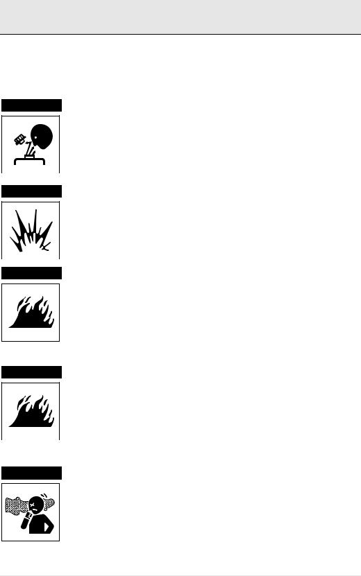
 DANGER
 WARNING
EN  CAUTION
DANGER indicates an imminently hazardous situation, which if not avoided, WILL result in death or serious injury.
WARNING indicates a potentially hazardous situation, which if not avoided, COULD result in death or serious injury.
CAUTION indicates a potentially hazardous situation, which if not avoided, may result in minor or moderate injury. This sign is also used to alert against unsafe practices.
The descriptions captioned by |
NOTICE |
are particularly important cautions for |
|
handling. If you ignore them, the performance of your machine may deteriorate leading to problems.
4
1.FOR YOUR SAFETY
1.2Safety Precautions
(Observe these instructions for your own safety!)
Precautions for Operation
 DANGER Filler Cap of Coolant Tank
Never open the cap of the coolant tank while the engine is still hot. Steam and hot water may spurt out and burn you seriously. Wait until the temperature of the coolant tank has dropped, wrap a cloth around the filler cap, loosen the cap very carefully and slowly to remove the system pressure before removing the cap. After inspection, refasten the cap firmly.
 DANGER Battery
 DANGER
 WARNING
 WARNING
Never smoke or permit sparks near the battery, because it may emit explosive hydrogen gas. Place the battery in a well-ventilated place.
Fuel |
EN |
|
|
Use only diesel fuel. Never use other fuels, including gasoline, kerosene, etc., because they could cause a fire. The wrong fuel could also cause the fuel injection pump and injector to fail due to lack of proper lubrication. Be sure to check that you have selected the correct diesel fuel before filling the fuel tank.
Do not use starting fluids or sprays. Their use may cause explosion, serious injury and engine damage.
Fire Prevention
Be sure to stop the engine and confirm that there are no open flames in the vicinity before fueling. If you do spill fuel, wipe such spillage carefully and dispose of the wiping materials properly. Wash your hands thoroughly with soap and water.
Never place oil or other flammable material in the engine room. Install a fire extinguisher near the engine room, and familiarize yourself with its use.
Exhaust Gas
Exhaust gas contains poisonous carbon monoxide and should not be inhaled.
Be sure to install ventilation ports or ventilators in the engine room and ensure good ventilation during engine operation.
5
1. FOR YOUR SAFETY
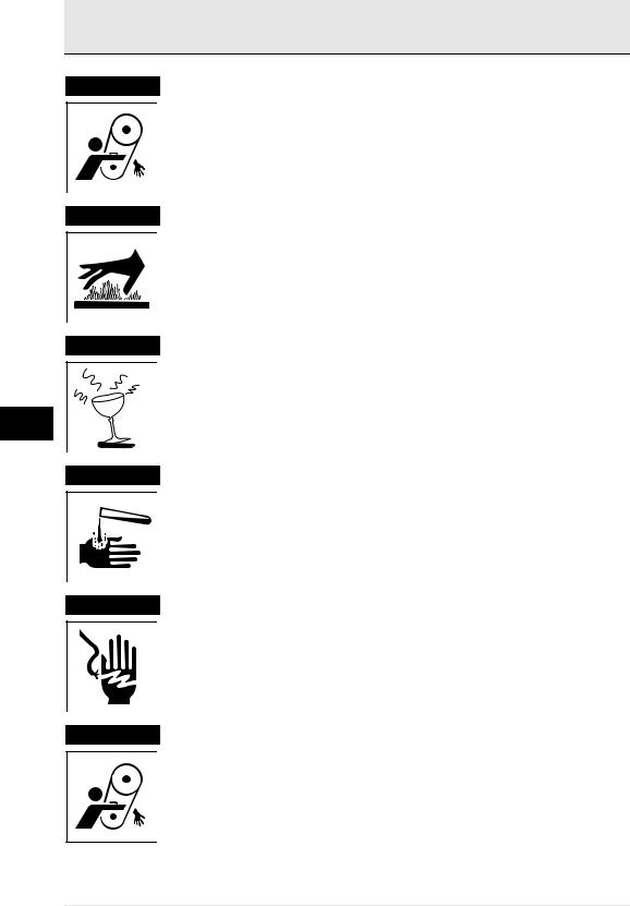
 WARNING Moving Parts
Do not touch or let your clothing get caught in the moving parts of the engine, such as the front drive shaft, V-belt or propeller shaft, during en-
gine operation. You will be injured.
Never operate the engine without covers on the moving parts.
 CAUTION Burns
 WARNING
EN
The whole engine is hot during operation and immediately after shut-down. The exhaust manifold, exhaust pipe and high pressure fuel lines are very hot. Never touch these parts with your body or clothing.
Alcohol
Never operate the engine while you are under the influence of alcohol. Never operate the engine when you are ill or not feeling well.
 DANGER Battery Fluid
 WARNING
 WARNING
Battery fluid is dilute sulphuric acid. It can blind you if it gets in your eyes, or burn your skin. Keep the fluid away from your body.
If you touch it, wash it off immediately with a large quantity of fresh water and call your doctor for treatment.
Fire by Electric Short-Circuits
Always turn off the battery switch before inspecting the electrical system.
Failure to do so could cause short-circuiting and fires.
Stop the engine before you service it.
Turn the battery switch off. If you must inspect while the engine is in operation, never touch moving parts. Keep your body and clothing well clear of all moving parts.
6

1. FOR YOUR SAFETY
 CAUTION Scalds
When extracting oil from the engine while it is still hot, don't let the oil splash on you.
Wait until the temperature has dropped before extracting cooling water from the engine. Don't let it splash on you.
DANGER |
Forbidden Modifications. |
|
|
Never release the limiting devices such as the engine speed limit, fuel |
|
|
injection limit, etc. |
|
|
Modification will impair the safety and performance of the product and |
|
|
shorten product life. |
|
|
Also note that any troubles arising from modification are not covered by |
|
|
our warranty. |
|
|
Precautions for Treating Waste. |
|
DANGER |
|
|
|
Never dispose of waste oil or other fluid in a field, sewer, river, or the |
|
|
sea. |
|
|
Treat waste matters safely observing regulations or laws. |
EN |
|
|
Ask a waste recovery company to collect it.
7
1. FOR YOUR SAFETY
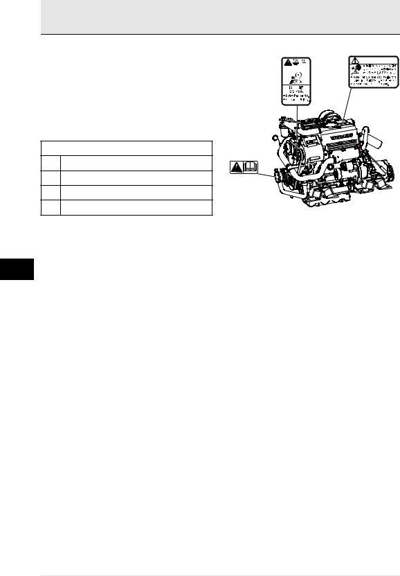
1.3 Warning Labels
Safety Precautions for Inspection
To insure safe operation, warning device labels have been attached. Their location is shown below and they should always be visible. Please replace if damaged or lost.
Product Safety Labels
C
No. Part Code No.
196630-12980
A 128377-07260
B128377-07350
C196630-12980
B A

 DANGER
WARNING
EN
8

2. PRODUCT EXPLANATION
2. PRODUCT EXPLANATION
2.1 Use, Propulsion System, Etc.
The engine is equipped with a marine gear or a sail drive unit. The marine gear output shaft connects with the propeller shaft.
In order to obtain full performance from your engine, it is imperative that you check the displacement and structure of the hull and use a propeller of the appropriate size. As new boats are used, owners add additional equipment and completely fill the fuel and water tanks adding to the overall displacement (weight) of the vessel. Extra canvas enclosures, bottom paint, and bottom fouling can add additional hull resistance. It is recommended that new vessels be propped so the engines can operate at 100-200 rpm above rated rpm to allow for some added weight and hull resistance. Failure to do so can lead to reduced vessel performance, lead to increased smoke levels and cause permanent damage to your engines.
The engine must be installed correctly with safe cooling water and exhaust piping and electrical wiring. Any auxiliary equipment attached to the engine should be easy to use and accessible for service.
To handle the drive equipment, propulsion systems (including the propeller) and other onboard equipment be sure to observe the instructions and cautions given in the operation manuals supplied by the shipyard and equipment manufacturers.
The laws of some countries may require hull and engine inspections, depending on the use, size and cruising area of the boat.
The installation, fitting and surveying of this engine all require specialized knowledge and engineering skills. Consult Yanmar's local subsidiary in your region or your distributor or dealer.
NOTICE
This engine is designed for pleasure boat applications.
The engine is designed to be operated at:
Maximum throttle (3600-3800 rpm) for |
EN |
less than 5% of total engine time. (30 |
|
|
|
minutes out of every 10 hours) |
|
Cruising Speed (3400 rpm or lower) for |
|
less than 90% of total engine time (9 |
|
hours out of every 10 hours) |
|
 WARNING
Never modify this product or release the limit devices (which limit engine speed, fuel injection quantity, etc.).
Modification will impair the safety and performance of the product and functions and shorten the product life.
Please note that any troubles arising from modification of the product will not be covered by our warranty.
9

2. PRODUCT EXPLANATION
DETAIL OF NAMEPLATE
The nameplate shown below is attached to the |
The nameplate shown below is attached to the |
engine. Check the engine's model, output, rpm and |
marine gear. Check the marine gear's model, gear |
serial number on the nameplate. |
ratio, oil used, oil quantity and serial number. |
Model |
|
MODEL |
KM |
|
GEAR RATIO |
|
|
Gear Model |
|
|
|
|
OIL |
SAE20/30HD |
|
|
|
||
Continuous power |
rpm |
OIL QTY. |
LTR. |
Speed of prop. shaft |
rpm |
NO. |
|
Fuel stop power kW |
rpm |
KANZAKI |
|
ENG.No. |
|
OSAKA |
JAPAN |
YANMAR DIESEL ENGINE |
|
|
|
|
YANMAR CO., LTD. |
|
|
|
MADE IN JAPAN |
|
|
EN
10
2.PRODUCT EXPLANATION
2.2Engine Specifications
Engine Model |
unit |
2YM15 |
|
|
|
|
Marine gear model |
- |
KM2P-1 |
SD-20 |
|
|
|
|
|
|
|
|
|
|
Use |
|
- |
Pleasure use |
|
|
|
|
|
|
|
|
|
|
Type |
|
- |
Vertical water-cooled 4-cycle diesel engine |
|
|
|
|
|
|
|
|
||
Combustion system |
- |
Swirl pre-combustion chamber |
|
|
||
|
|
|
|
|
|
|
Number of cylinders |
- |
2 |
|
|
|
|
|
|
|
|
|
|
|
Bore x stroke |
|
mm(inch) |
70x74(2.76x2.91) |
|
|
|
|
|
|
|
|
|
|
Displacement |
|
L |
0.570 |
|
|
|
|
|
|
|
|
|
|
Continuous |
Output at crankshaft/ |
kW(hp)/ |
9.4(12.8)/3489(at Fuel temp. 25°C)[2] |
|
|
|
power |
Engine speed |
min-1[1] |
|
|
|
|
Fuel stop |
Output at crankshaft/ |
kW(hp)/ |
10.3(14.0)/3600(at Fuel temp. 25°C) [2] |
|
|
|
power |
Engine speed |
min-1[1] |
/10.0(13.6)/3600(at Fuel temp. 40°C) [2] |
|
|
|
|
Output at propeller/ |
kW(hp)/ |
10.0(13.6)/3600(at Fuel temp. 25°C) [2] |
- |
|
|
|
Engine speed |
min-1[1] |
/9.7(13.2)/3600(at Fuel temp. 40°C) [2] |
|
|
|
|
|
|
|
|
|
|
Installation |
|
- |
Flexible mounting |
|
|
|
|
|
|
|
|
|
|
Fuel injection opening pressure |
MPa |
12.3+0.98-0 |
|
|
|
|
|
|
|
|
|
|
EN |
Direction of |
Crankshaft |
- |
Counter-clockwise viewed from stern |
|
||
rotation |
|
|
|
|
|
|
Propeller shaft |
- |
Clockwise viewed from stern |
- |
|
|
|
|
|
|||||
|
|
|
||||
|
(Ahead) |
|
|
|
|
|
|
|
|
|
|
|
|
Cooling system |
- |
Fresh water-cooling with heat exchanger |
|
|
||
|
|
|
|
|
||
Lubrication system |
- |
Complete enclosed forced lubrication |
|
|
||
|
|
|
|
|
||
Cooling water capacity (fresh) |
L(quart) |
Engine 3.0 (3.2), Coolant recovery tank: 0.8(0.8) |
|
|
||
|
|
|
|
|
|
|
Lubricating |
Rake angle |
°(deg) |
at rake angle 8° |
at rake angle 0° |
|
|
oil capacity |
|
|
|
|
|
|
Total[3] |
L(quart) |
2.0(2.1) |
1.8(1.9) |
|
|
|
(engine) |
|
|
||||
Effective[4] |
|
0.95(1.0) |
0.9(1.0) |
|
|
|
|
|
|
|
|||
Starting sys- |
Type |
- |
Electric |
|
|
|
tem |
|
|
|
|
|
|
Starting motor |
V-kW |
DC 12V - 1.4 kW |
|
|
|
|
|
|
|
|
|||
|
|
|
|
|
|
|
|
AC generator |
V-A |
12V - 60A (12V - 80A optional) |
|
|
|
|
|
|
|
|
|
|
Engine |
Overall length |
mm(inch) |
613(24.1) |
- |
|
|
dimension |
|
|
|
|
|
|
Overall width |
|
463(18.2) |
|
|
|
|
|
|
|
|
|
||
|
|
|
|
|
|
|
|
Overall height |
|
528(20.8) |
|
|
|
|
|
|
|
|
|
|
Engine dry mass (include marine |
kg |
113 |
134(with SD20) |
|
|
|
gear) |
|
|
|
|
|
|
|
|
|
|
|
|
|
[1]hp = 0.7355 kW
[2]Fuel temperature at the inlet of the fuel injection pump.
[3]The "Total" oil quantity includes oil in oil pan, channels, coolers and filter.
[4]The effective amount of oil shows the difference in maximum scale of the dipstick and minimum scale.
Note: Fuel condition: Density at 15 ºC = 0.842
Rating condition ISO 3046-1, at fuel temp. 25°C ; ISO 3046-1, at fuel temp. 40°C inlet; ISO 8665. At FO pump inlet.
11

2. PRODUCT EXPLANATION
|
|
Engine Model |
unit |
3YM20 |
3YM30 |
|||||
|
|
Marine gear model |
- |
KM2P-1 |
|
SD-20 |
KM2P-1 |
|
SD-20 |
|
|
|
|
|
|
|
|
|
|
||
|
|
Use |
|
- |
Pleasure use |
Pleasure use |
||||
|
|
|
|
|
|
|
||||
|
|
Type |
|
- |
Vertical water-cooled 4-cycle diesel |
Vertical water-cooled 4-cycle diesel |
||||
|
|
|
|
|
engine |
|
engine |
|
||
|
|
|
|
|
|
|||||
|
|
Combustion system |
- |
Swirl pre-combustion chamber |
Swirl pre-combustion chamber |
|||||
|
|
|
|
|
|
|
|
|
|
|
|
|
Number of cylinders |
- |
3 |
|
|
3 |
|
|
|
|
|
|
|
|
|
|||||
|
|
Bore x stroke |
mm(inch) |
70x74(2.76x2.91) |
76x82(2.99x3.23) |
|||||
|
|
|
|
|
|
|
|
|||
|
|
Displacement |
L |
1.115 |
|
1.115 |
|
|||
|
|
|
|
|
|
|
|
|
||
|
|
Continu- |
Output at |
kW(hp)/ |
14.7(20.0)/3489(at Fuel temp. 25°C)[2] |
20.1(27.3)/3489(at Fuel temp. 25°C) [2] |
||||
|
|
ous |
crankshaft/ |
min-1[1] |
|
|
|
|
|
|
|
|
power |
Engine speed |
|
|
|
|
|
|
|
|
|
|
|
|
|
|
||||
|
|
Fuel stop |
Output at |
kW(hp)/ |
16.2(22.0)/3600(at Fuel temp. 25°C) [2] |
22.1(30.0)/3600(at Fuel temp. 25°C) [2] |
||||
|
|
power |
crankshaft/ |
min-1[1] |
/15.3(20.8)/3600(at Fuel temp. 40°C) [2] |
/21.3(29.0)/3600(at Fuel temp. 40°C) [2] |
||||
|
|
|
Engine speed |
|
|
|
|
|
|
|
|
|
|
Output at pro- |
kW(hp)/ |
15.7(21.3)/3600(at |
|
- |
21.4(29.1)/3600(at |
|
- |
|
|
|
peller/Engine |
min-1[1] |
Fuel temp. 25°C) [2] |
|
|
Fuel temp. 25°C) [2] |
|
|
|
|
|
speed |
|
/14.9(20.2)/3600(at |
|
|
/20.7(28.1)/3600(at |
|
|
|
|
|
|
|
Fuel temp. 40°C) [2] |
|
|
Fuel temp. 40°C) [2] |
|
|
|
|
|
|
|
|
|
|
|
||
|
|
Installation |
|
- |
Flexible mounting |
Flexible mounting |
||||
|
|
|
|
|
|
|||||
|
|
Fuel injection opening pres- |
MPa |
12.3+0.98-0 |
12.3+0.98-0 |
|||||
|
|
sure |
|
|
|
|
|
|
|
|
EN |
|
|
|
|
|
|
|
|
||
|
|
|
|
|
|
|
|
|||
|
Direction |
Crankshaft |
- |
Counter-clockwise viewed from stern |
Counter-clockwise viewed from stern |
|||||
|
|
of rotation |
|
|
|
|
|
|
|
|
|
|
Propeller shaft |
- |
Clockwise viewed |
|
- |
Clockwise viewed |
|
- |
|
|
||||||||||
|
|
|
(Ahead) |
|
from stern |
|
|
from stern |
|
|
|
|
|
|
|
|
|
|
|
||
|
|
Cooling system |
- |
Fresh water-cooling with heat |
Fresh water-cooling with heat |
|||||
|
|
|
|
|
exchanger |
exchanger |
||||
|
|
|
|
|
|
|||||
|
|
Lubrication system |
- |
Complete enclosed forced lubrication |
Complete enclosed forced lubrication |
|||||
|
|
|
|
|
|
|||||
|
|
Cooling water capacity |
L(quart) |
Engine 4.5 (4.8), Coolant recovery tank: |
Engine 4.9(5.2), Coolant recovery tank: |
|||||
|
|
(fresh) |
|
|
0.8(0.8) |
0.8(0.8) |
||||
|
|
|
|
|
|
|
|
|
|
|
|
|
Lubricat- |
Rake angle |
°(deg) |
at rake angle 8° |
|
at rake angle 0° |
at rake angle 8° |
|
at rake angle 0° |
|
|
ing oil |
|
|
|
|
|
|
|
|
|
|
Total[3] |
L(quart) |
2.7(2.85) |
|
2.4(2.5) |
2.8(3.0) |
|
2.5(2.6) |
|
|
|
capacity |
|
|
||||||
|
|
|
|
|
|
|
|
|
|
|
|
|
(engine) |
Effective[4] |
|
1.4(1.5) |
|
1.5(1.6) |
1.4(1.5) |
|
1.5(1.6) |
|
|
Starting |
Type |
- |
Electric |
|
Electric |
|||
|
|
system |
|
|
|
|
|
|
|
|
|
|
Starting motor |
V-kW |
DC 12V - 1.4 kW |
DC 12V - 1.4 kW |
|||||
|
|
|
||||||||
|
|
|
|
|
|
|
||||
|
|
|
AC generator |
V-A |
12V - 60A (12V - 80A optional) |
12V - 60A (12V - 80A optional) |
||||
|
|
|
|
|
|
|
|
|
|
|
|
|
Engine |
Overall length |
mm(inch) |
693(27.3) |
|
- |
715(28.1) |
|
- |
|
|
dimen- |
|
|
|
|
|
|
|
|
|
|
Overall width |
|
463(18.2) |
463(18.2) |
|||||
|
|
sion |
|
|||||||
|
|
|
|
|
|
|
|
|
|
|
|
|
|
Overall height |
|
528(20.8) |
545(21.5) |
||||
|
|
|
|
|
|
|
|
|
|
|
|
|
Engine dry mass (include |
kg |
130 |
|
151(with SD20) |
133 |
|
154(with SD20) |
|
|
|
marine gear) |
|
|
|
|
|
|
|
|
|
|
|
|
|
|
|
|
|
|
|
[1]hp = 0.7355 kW
[2]Fuel temperature at the inlet of the fuel injection pump.
[3]The "Total" oil quantity includes oil in oil pan, channels, coolers and filter.
[4]The effective amount of oil shows the difference in maximum scale of the dipstick and minimum scale.
Note: Fuel condition: Density at 15 ºC = 0.842
Rating condition ISO 3046-1, at fuel temp. 25°C ; ISO 3046-1, at fuel temp. 40°C inlet; ISO 8665. At FO pump inlet.
12

2. PRODUCT EXPLANATION
Marine gear |
Model |
Unit |
KM2P-1(S) |
KM2P-1(G) |
KM2P-1(GG) |
SD20 (coupled |
or Sail Drive |
|
|
|
|
|
at boat builder) |
|
|
|
|
|
|
|
|
Type |
- |
Mechanical cone clutch |
Dog clutch |
||
|
|
|
|
|
|
|
|
Reduction ratio (For- |
- |
2.21/3.06 |
2.62/3.06 |
3.22/3.06 |
2.64/2.64 |
|
ward/Reverse) |
|
|
|
|
|
|
|
|
|
|
|
|
|
Propeller speed (For- |
min-1 |
1580/1140 |
1332/1140 |
1083/1140 |
1322 |
|
ward/Reverse)[1] |
|
|
|
|
|
|
Lubrication system |
- |
|
Splash |
|
Oil bath |
|
|
|
|
|
|
|
|
Lubricating oil capacity |
L (quart) |
|
0.3 (0.32) |
|
2.2 (2.3) |
|
|
|
|
|
|
|
|
Mass |
kg |
|
9.8 |
|
30 |
|
|
|
|
|
|
|
[1] At continuous power engine speed 3489 min-1
EN
13
2.PRODUCT EXPLANATION
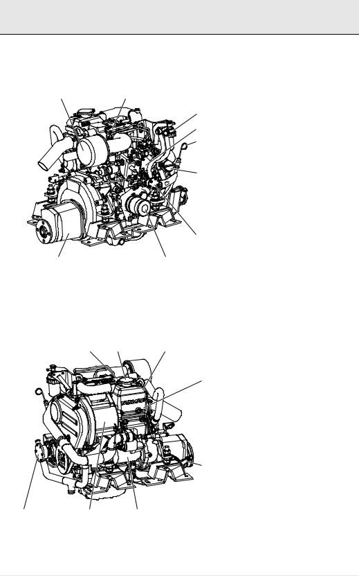
2.3Names of Parts
2YM15 Operation Side
A B
C
D
E
F
G
|
|
I |
|
H |
EN |
|
|
||
A |
Intake silencer |
F |
Oil filler cap |
|
|
B |
Intake manifold |
G Fuel feed pump |
|
|
||||
|
C |
Fuel filter |
H |
Lubricating oil filter |
|
D |
Fuel injection pump |
I |
Marine gear |
|
E |
Dipstick |
|
|
|
Non Operation Side |
|
|
|
|
|
D |
C |
E |
F
H
|
A |
I |
G |
|
A |
Seawater pump |
|
F |
Exhaust manifold |
C Filler cap |
|
G |
Starter motor |
|
D Engine name plate (on the rocker arm cover)H |
Shift lever |
|||
E |
Coolant tank / Heat exchanger |
I |
Alternator |
|
14

2. PRODUCT EXPLANATION
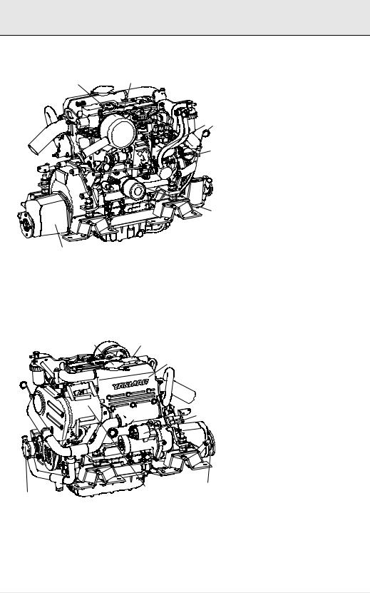
3YM20 Operation Side
A B
C
D E
F
 G
G
H
I
A |
Intake silencer |
F |
Oil filler cap |
B |
Intake manifold |
G Fuel feed pump |
|
C |
Fuel filter |
H |
Lubricating oil filter |
D |
Fuel injection pump |
I |
Marine gear |
E |
Dipstick |
|
|
EN
Non Operation Side
C D
E
F
 G
G
I H
A
A |
Seawater pump |
F |
Exhaust manifold |
C Filler cap |
G |
Starter motor |
|
D Engine name plate (on the rocker arm cover)H |
Shift lever |
||
E |
Coolant tank / Heat exchanger |
I |
Alternator |
15
2. PRODUCT EXPLANATION
3YM30 Operation Side
A B
C
 D E
D E
F
 G
G
H
|
|
I |
|
|
|
A |
Intake silencer |
F |
Oil filler cap |
EN |
B |
Intake manifold |
G Fuel feed pump |
|
|
C |
Fuel filter |
H |
Lubricating oil filter |
|
D |
Fuel injection pump |
I |
Marine gear |
|
E |
Dipstick |
|
|
Non Operation Side
C D
E
 F
F
G
|
|
I |
H |
|
A |
|
|
|
|
|
|
A |
Seawater pump |
F |
Exhaust manifold |
C |
Filler cap |
G |
Starter motor |
D Engine name plate (on the rocker arm cover)H |
Shift lever |
||
E Coolant tank / Heat exchanger |
I |
Alternator |
|
16

2.PRODUCT EXPLANATION
2.4Major Service of Parts
Name of part |
Function |
|
|
|
|
|
|
Fuel filter |
Removes dirt and water from fuel. Drain the filter periodically. The element (filter) |
|
|
should be changed. See maintenance section 4.3.5 |
|
|
|
|
|
|
|
|
|
|
|
Fuel feed pump |
Pumps fuel from tank to the fuel injection pump. |
|
|
|
|
|
|
Priming lever |
Moving the priming lever up and down feeds the fuel. The priming lever is used to |
|
|
bleed air from the fuel system after running out of fuel. |
|
|
|
|
|
|
|
|
|
|
|
Filler port (engine) |
Filler port for engine lubricating oil. |
|
|
|
|
|
|
Filler port (marine |
Filler port for marine gear lubricating oil. |
|
|
gear) |
|
|
|
|
|
|
|
Lubricating oil fil- |
Filters fine metal fragments and carbon from the lubricating oil. Filtered lubricating oil is |
|
|
ter |
distributed to the engine's moving parts. |
|
|
|
There are two cooling systems: fresh water and seawater. The engine’s combustion |
|
|
Cooling System |
heat is cooled by the fresh water/coolant in a closed circuit. The fresh water is cooled |
|
|
by seawater using heat exchanger. The seawater also cools the engineand gear-oil |
|
|
|
|
|
|
|
|
(and depending on the model also intake air) through coolers in an open circuit. |
|
|
|
|
|
|
Fresh water pump |
The centrifugal water pump circulates fresh cooling water inside the engine. The fresh |
|
|
water pump is driven by the V-belt. |
|
|
|
|
|
|
|
|
|
|
EN |
Seawater pump |
Pumps seawater from outside the vessel to the engine by passing through the engine’s |
|
|
coolers. The seawater pump is belt driven and has a replaceable rubber impeller. |
|
|
|
|
|
|
|
|
|
|
|
Fresh water/cool- |
The filler cap on the coolant tank covers the water supply port. The cap has a pressure |
|
|
regulating valve. When the cooling water temperature rises the pressure rises inside |
|
|
|
ant filler cap |
|
|
|
the fresh water system. |
|
|
|
|
|
|
|
|
|
|
|
|
The pressure regulating valve releases vapour and hot water overflows to the coolant |
|
|
Coolant recovery |
recovery tank When the engine stops and cooling water cools, the pressure in the cool- |
|
|
ing water tank also drops very low. The filler cap valve then opens to send water back |
|
|
|
tank |
|
|
|
from the coolant recovery tank. This minimizes cooling water consumption. Fresh |
|
|
|
|
|
|
|
|
water/coolant level can easily be checked and refilled in this tank. |
|
|
|
|
|
|
Intake silencer |
The intake silencer guards against dirt in the air and reduces the noise of air intake. |
|
|
|
|
|
|
Nameplates |
Nameplates are provided on the engine and the marine gear and have the model, |
|
|
serial number and other data. |
|
|
|
|
|
|
|
|
|
|
|
Starter |
Starter motor for the engine. Powered by the battery. |
|
|
|
|
|
|
Alternator |
Rotated by belt drive, generates electricity and charges the battery. |
|
|
|
|
|
|
17
 Loading...