

Yamaha Audio P4500, P3200, P1600 User Manual

POWER AMPLIFIER
Owner's Manual
Mode d'emploi
Bedienungsanleitung
Manual de instrucciónes
TEMP
PROTECTION
POWER
ON OFF
EEEngine
15
CLIP
SIGNAL
20
25
10
30
6
40
3
–dB∞ 0 ∞ 0
15
10
6
3
AB
20
25
30
40
M

Introduction
Thank you for purchasing a Yamaha P4500/3200/1600 series power amplifier.
This series of audio amps was developed from Yamaha's wealth of experience in building PA
equipment and its tradition of careful attention to every detail of circuit design. These amps
feature high power and superb quality together with superior reliability and stability, guaranteeing the highest possible audio performance.
Main features of the P4500/P3200/P1600 series
• Three types of input jack (balanced XLR type connectors, balanced phone jacks, and barrier
strip), and five-way binding post output jacks are provided, allowing use in a wide variety
of situations including installed applications.
• Three operating modes are provided: STEREO mode in which CHANNEL A and B operate
independently, PARALLEL mode in which a mono source is output by two amp systems, and
BRIDGE mode in which the unit operates as a single high-power amplifier.
• A SIGNAL indicator and CLIP indicator is provided for each channel.
• The PROTECTION indicator shows the status of protective circuitry such as power-on/off
protection, output muting, and the DC detection circuit. The TEMP indicator warns of heat
sink overheating.
• Variable-speed low-noise fan(s) ensures high reliability even under demanding conditions.
This owner's manual covers the three models P4500, P3200 and P1600. In order to take full
advantage of your power amp and enjoy long and trouble-free operation, please read this owner's
manual carefully before use.
English
IMPORTANT NOTICE FOR
THE UNITED KINGDOM
Connecting the Plug and Cord
WARNING: THIS APPARATUS MUST BE EARTHED
IMPORTANT: The wires in this mains lead are coloured in accordance with
the following code:
GREEN-AND-YELLOW : EARTH
BLUE : NEUTRAL
BROWN : LIVE
As the colours of the wires in the mains lead of this apparatus may not
correspond with the coloured markings identifying the terminals in your
plug, proceed as follows:
The wire which is coloured GREEN and YELLOW must be connected to
the terminal in the plug which is marked by the letter E or by the safety earth
symbol or coloured GREEN and YELLOW.
The wire which is coloured BLUE must be connected to the terminal which
is marked with the letter N or coloured BLACK.
The wire which is coloured BROWN must be connected to the terminal
which is marked with the letter L or coloured RED.
* This applies only to products distributed by YAMAHA KEMBLE
MUSIC (U.K.) LTD.

Precautions
1. Avoid excessive heat, humidity, dust and vibration.
Keep the unit away from locations where it is likely to be
exposed to high temperatures or humidity — such as
near radiators, stoves, etc. Also avoid locations which
are subject to excessive dust accumulation or vibration
which could cause mechanical damage.
2. Ventilation
Allow a distance of 10 cm between the unit and the wall
so that heat generated from the unit will be released
effectively. Also, allow enough space between the unit
and other devices. If you mount the unit in an audio rack,
keep a space of 10 cm on the top panel, and a space of
1 cm to the side panel. Remove the rear panel of the rack
or open a vent hole. If heat release is inadequate, the unit
will retain heat inside the unit, which may cause a fire.
3. Avoid physical shocks.
Strong physical shocks to the unit can cause damage.
Handle it with care.
4. Do not open the case or attempt repairs or modifications yourself.
This product contains no user-serviceable parts. Refer
all maintenance to qualified Yamaha service personnel.
Opening the case and/or tampering with the internal
circuitry will void the warranty.
5. Make sure power is off before making or removing
connections.
Always turn the power OFF prior to connecting or
disconnecting cables. This is important to prevent damage to the unit itself as well as other connected equipment.
6. Handle cables carefully.
Always plug and unplug cables — including the AC cord
— by gripping the connector, not the cord.
7. Clean with a soft dry cloth.
Never use solvents such as benzine or thinner to clean
the unit. Wipe clean with a soft, dry cloth.
8. Always use the correct power supply.
Make sure that the power supply voltage specified on the
rear panel matches your local AC mains supply. Also
make sure that the AC mains supply can deliver more
than enough current to handle all equipment used in your
system.
Contents
Controls and Functions ............................................................. 2
Front Panel........................................................................... 2
Rear Panel ........................................................................... 3
Modes: STEREO/P ARALLEL/BRIDGE................................ 4
SPEAKER IMPEDANCE...................................................... 4
Caution for Speaker Connection ............................................... 5
Rack Mounting .......................................................................... 6
Mounting in an EIA standard rack ....................................... 6
Mounting four or fewer amps in an open-backed rack......... 6
Mounting five or more amps, or when (even with four or
fewer units) the back of the rack cannot be left open.......... 6
Portable Rack Mounting ...................................................... 7
Positioning the Housed Amplifier......................................... 7
Specifications ............................................................................ 8
General Specifications......................................................... 8
Block Diagram...................................................................... 9
Dimensions .......................................................................... 9
Performance Graphs.......................................................... 10
Troubleshooting ...................................................................... 10
Controls and Functions
■ Front Panel
23
TEMP
PROTECTION
POWER
ON OFF
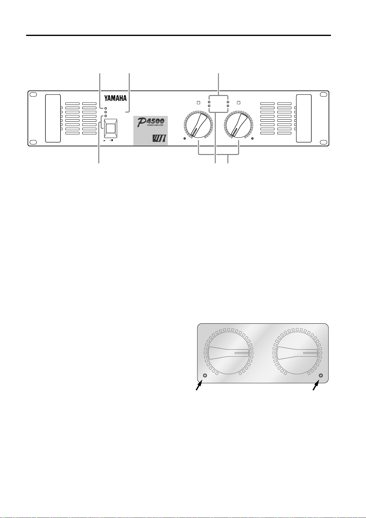
1 POWER switch and indicator
This is the main POWER switch. Press to power ON the
amplifier. Press again to power OFF. The POWER
indicator lights up when the amplifier is powered ON.
2 TEMP indicator
When the temperature of the heat sink exceeds 85
degrees Celsius, this indicator will light red.
3 PROTECTION indicator
This red LED indicator lights up for approximately 3
seconds when the amplifier is powered ON, indicating
that the soft-start protection system is working. No
sound is output during soft-start up. If one of the protection systems is activated during normal use, this indicator lights up and no sound is output. The speaker system
is actually disconnected from the amplifier outputs when
this indicator lights up. The protection systems are
activated when overheating occurs or a DC voltage is
present at the amplifier outputs. If the problem is corrected, the protection systems deactivate automatically,
this indicator goes out, and normal amplifier operation is
resumed.
EEEngine
4
CLIP
AB
SIGNAL
15
20
25
30
40
10
30
6
3
–dB∞ 0 ∞ 0
5
4 CLIP indicators
These red LED indicators light up when the respective
channel’s output signal distortion exceeds 1% (i.e. clipping). Output signal clipping is usually due to excessive
input signal levels.
5 SIGNAL indicators
These green LED indicators light up when the respective
channel’s output signal exceeds 2 Vrms. This is equivalent to 1/2 watt into 8Ω, 1 W into 4Ω.
6 Volume controls
These volume controls allow you to adjust the volume
level in 31 steps in the range between –∞ dB and 0 dB.
To fix the volume setting by protecting the controls,
install the included security cover over the controls and
tighten the screws in the holes as shown below.
20
25
30
40
15
20
25
40
10
6
3
61
15
10
6
3
–dB∞ 0 ∞ 0
20
25
30
40
15
10
6
3
2
■ Rear Panel
SPEAKERS
CHANNEL B CHANNEL A
STEREO
BRIDGE
SPEAKERS
CHANNEL B CHANNEL A
STEREO
BRIDGE
3214
INPUT SPEAKERS
CHANNEL B CHANNEL A
GG
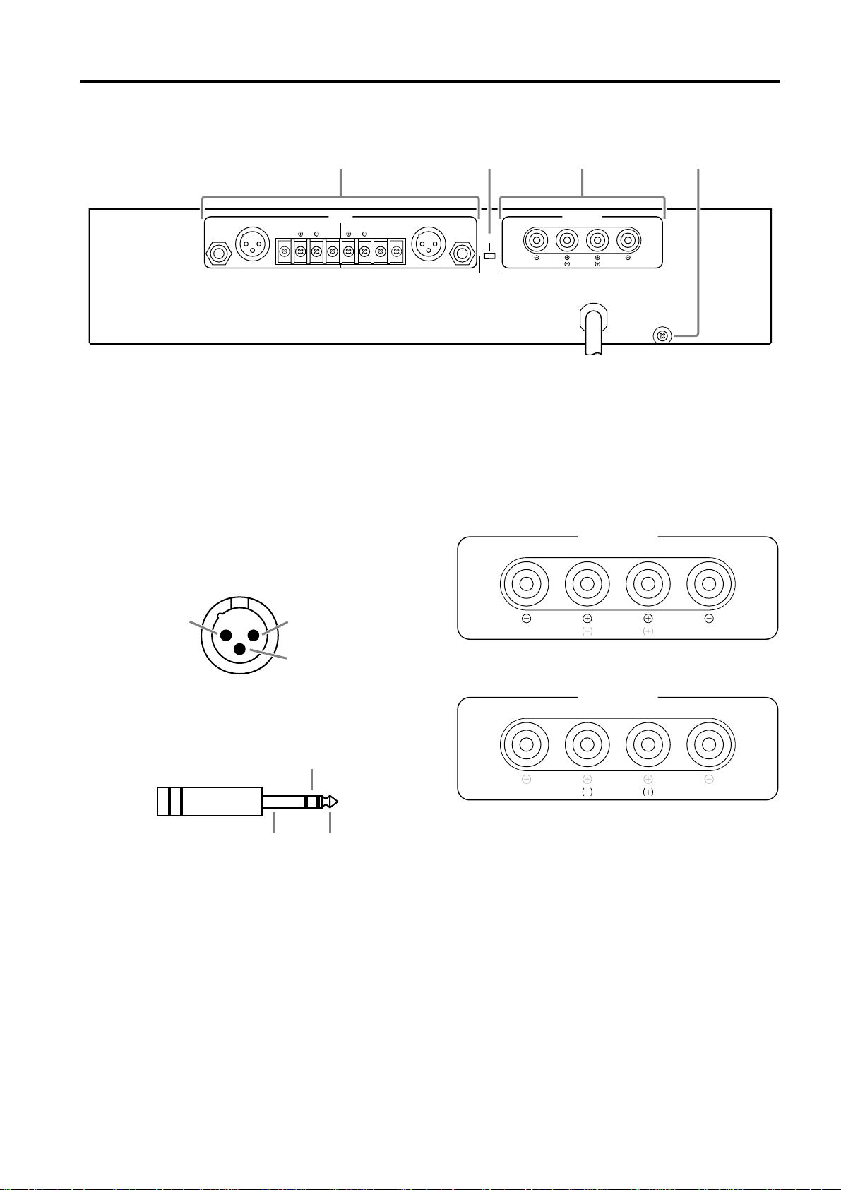
1 INPUT terminals (CHANNEL A, B)
Three types of balanced terminals for channels A and B
are provided.
Channel A input terminal is used in Bridge and Parallel
mode.
• XLR-3-31 type connector
They are wired pin 1–ground, pin 2–hot (+), and pin 3 cold
(-).
GroundHot
1
2
3
Cold
(BRIDGE)
(PARALLEL)
BRIDGE
STEREO PARALLEL
CHANNEL B CHANNEL A
STEREO
BRIDGE
MAX. OUTPUT 450W/4Ω (STEREO)
MAX. OUTPUT 900W/8Ω (BRIDGE)
(STEREO)
4-8Ω/SP
(BRIDGE)
8-16Ω/SP
3 SPEAKERS terminals
For polarity in each mode, refer to the following diagram.
• STEREO, PARALLEL mode
• BRIDGE mode
• Phone jack
They are wired tip–hot (+), ring–cold (-), and sleeve–
ground.
Ring
Sleeve Tip
• Barrier strip
Hot (+), Cold (-) and Ground (G).
2 STEREO/BRIDGE/PARALLEL switch
This slide switch is used to set the amplifier operating
mode: STEREO, BRIDGE or PARALLEL.
For details on the functionality of each mode, refer to
“Modes” on page 4.
In BRIDGE mode, the (-) jacks of CHANNELS A and
B are not used.
The minimum impedance for the connected speaker
system is specified in “Speaker Impedance” on page 4.
4 GND terminals
This is the grounding screw terminal. If hum or noise
occurs, ground (earth) the unit via this jack, or try
connecting it to the chassis of the mixer or preamp, etc.
3
■ Modes: STEREO/PARALLEL/BRIDGE
STEREO mode
In this mode, channels A and B operate independently
(as a conventional stereo amp).
The CHANNEL A input signal will be output from the
CHANNEL A output jacks, and the CHANNEL B input
signal will be output from the CHANNEL B output
jacks.
PARALLEL mode
In this mode, the CHANNEL A input signal will be
output from the output jacks of both channels A and B.
The CHANNEL B input jack is not used. The (channel)
A
and B volumes can be adjusted independently.
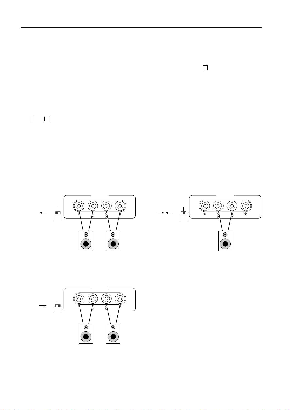
■ SPEAKER IMPEDANCE
In STEREO and PARALLEL modes, the minimum load
(=speaker) impedance is 4Ω. In BRIDGE mode it is 8Ω.
Make sure that the impedance does not fall below this
specified impedance.
STEREO mode connections
BRIDGE mode
In this mode, the CHANNEL A input signal will be
output from the BRIDGE output jacks. In this case, use
the front panel (channel)
volume control to adjust the
A
volume.
BRIDGE mode connections
SPEAKERS
CHANNEL B CHANNEL A
Set to STEREO
BRIDGE
STEREO PARALLEL
MAX. OUTPUT 450W/4Ω (STEREO)
MAX. OUTPUT 900W/8Ω (BRIDGE)
–+
4Ω min. 4Ω min.
Speaker System
PARALLEL mode connections
SPEAKERS
CHANNEL B CHANNEL A
Set to PARALLEL
BRIDGE
STEREO PARALLEL
MAX. OUTPUT 450W/4Ω (STEREO)
MAX. OUTPUT 900W/8Ω (BRIDGE)
– +
STEREO
BRIDGE
STEREO
BRIDGE
–+
– +
Set to BRIDGE
BRIDGE
STEREO PARALLEL
SPEAKERS
CHANNEL B CHANNEL A
STEREO
BRIDGE
MAX. OUTPUT 450W/4Ω (STEREO)
MAX. OUTPUT 900W/8Ω (BRIDGE)
– +
8Ω min.
Speaker System
4Ω min. 4Ω min.
Speaker System
4
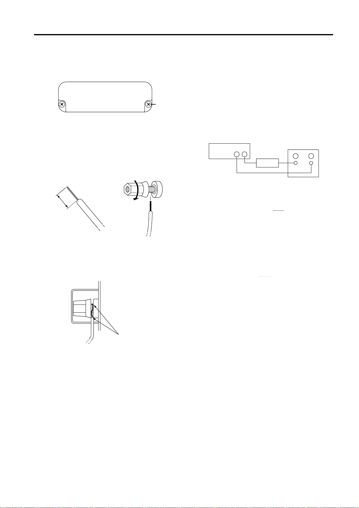
Caution for Speaker Connection
1. Turn off the POWER switch.
2. Remove the cover attachment screw(s) and remove the
protective cover from the speaker terminals.
Screw
3. After removing approx. 10 mm of insulation from the
ends of the speaker cables, pass the bare ends of the
speaker wires through the holes in the corresponding
speaker terminals and tighten the terminals to securely
clamp the wires.
Refer to page 3 for speaker porality.
10mm
• Speaker fuse
The output capacity of your amplifier is very high: 460
W+460 W (8Ω) in stereo and 1240 W (8Ω) in monaural
on the P4500; 340 W+340 W (8Ω) in stereo and 880 W
(8Ω) in monaural on the P3200; 160 W+160 W (8Ω) in
stereo and 400 W (8Ω) in monaural on the P1600. Be
sure to use a speaker system that has sufficient input
capacity.
If the input capacity of your speaker system is lower than
the rated output of the power amplifier, you can protect
your speakers by connecting a fuse serially between the
speaker and amplifier as shown below.
Power amplifier
_
+ _
Fuse
Speaker system
+
Use the following formula to determine the fuse capacity
according to the speaker’s input capacity.
2
Po = I R → I = √Po/R
At this time make sure that the bare ends of the speaker
cables do not extend from the terminals in such a way
that they touch the chassis.
4. Reattach the protective cover over the speaker terminals.
P0 [W] : Speaker’s continuous input capacity (noise or
RMS)
R [Ω] : Speaker’s nominal impedance
I [A] : Required fuse capacity
ex.) Speaker’s continuous input capacity : 100 W
Speaker’s impedance : 8Ω
I = √100/8
In this example, the required fuse capacity is calculated
as 3.5 [A].
• Speaker cable
If you use a long speaker cable, use as thick a cable as
possible to prevent deterioration of the damping factor
or power loss inside the cable.
5
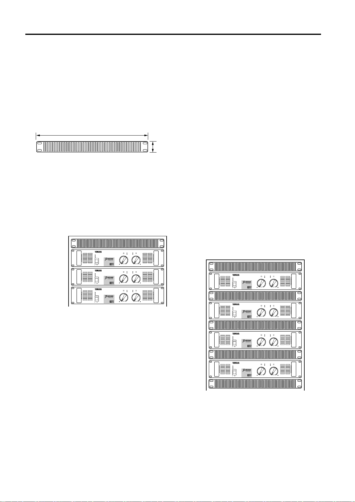
Rack Mounting
■ Mounting in an EIA standard rack
If multiple high-power amp units are mounted in a rack with poor ventilation, the heat from the amps will cause the interior
of the amp to become very hot, causing the performance of the amps to be impaired. When mounting amps in a rack, you
must make provision for ventilation so that the heat can escape.
When mounting amps in a rack, please attach ventilation panels above and below the amp to allow air circulation. When
doing so, it is necessary for 35% or more of the entire surface area of a 1U size panel to be open.
Air circulation will be even better if the top surface of the rack has ventilation openings.
Ventilation panel
Yamaha provides an optional 1U-size ventilation panel VP1.
480
44
Unit: mm
■ Mounting four or fewer amps in
an open-backed rack
Install the ventilation panel above the amps, as shown in
the following figure.
Ventilation panel
(attach to the front
or rear of the rack)
TEMP
PROTECTION
POWER
ON OFF
EEEngine
TEMP
PROTECTION
POWER
ON OFF
EEEngine
TEMP
PROTECTION
POWER
ON OFF
EEEngine
CLIP
AB
SIGNAL
15
20
25
25
10
30
30
6
40
40
3
–dB∞ 0 ∞ 0
CLIP
AB
SIGNAL
15
20
25
25
10
30
30
6
40
40
3
–dB∞ 0 ∞ 0
CLIP
AB
SIGNAL
15
20
25
25
10
30
30
6
40
40
3
–dB∞ 0 ∞ 0
15
20
10
6
3
15
20
10
6
3
15
20
10
6
3
■ Mounting five or more amps, or
when (even with four or fewer
units) the back of the rack cannot
be left open
Install ventilation panels above and below each amp, as
shown in the following figure.
CLIP
AB
TEMP
PROTECTION
POWER
ON OFF
EEEngine
TEMP
PROTECTION
POWER
ON OFF
EEEngine
TEMP
PROTECTION
POWER
ON OFF
EEEngine
TEMP
PROTECTION
POWER
ON OFF
EEEngine
SIGNAL
15
20
25
25
10
30
30
6
40
40
3
–dB∞ 0 ∞ 0
CLIP
AB
SIGNAL
15
20
25
25
10
30
30
6
40
40
3
–dB∞ 0 ∞ 0
CLIP
AB
SIGNAL
15
20
25
25
10
30
30
6
40
40
3
–dB∞ 0 ∞ 0
CLIP
AB
SIGNAL
15
20
25
25
10
30
30
6
40
40
3
–dB∞ 0 ∞ 0
15
20
10
6
3
15
20
10
6
3
15
20
10
6
3
15
20
10
6
3
6
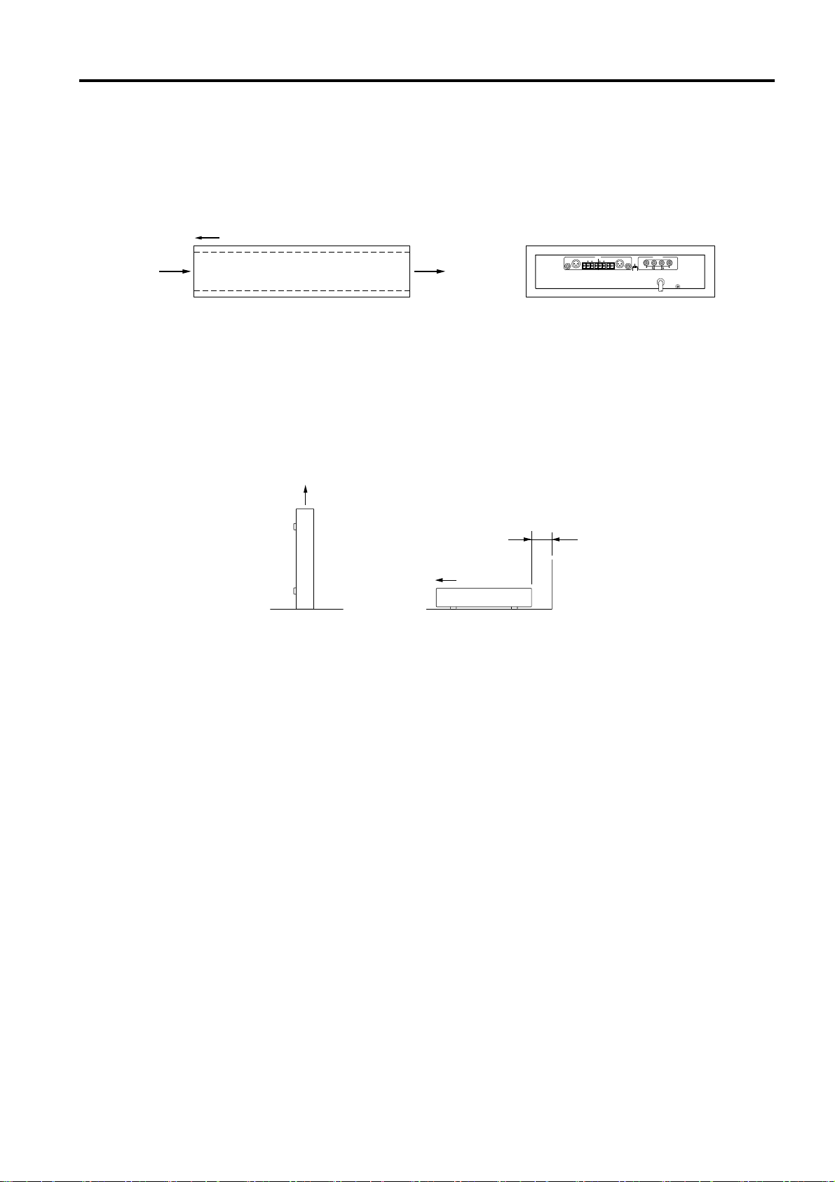
■ Portable Rack Mounting
The amplifier intakes cool air through the front panel and exhausts warm air out the rear panel. When mounting amplifiers
in a portable rack, make sure the rear panel is completely open for ventilation.
(Rear View)(Side View)
Front
Air intake Air exhaust
Completely open
INPUT SPEAKERS
(BRIDGE)
CHANNEL B CHANNEL A
GG
CHANNEL B CHANNEL A
(PARALLEL)
BRIDGE
STEREO PARALLEL
MAX. OUTPUT 450W/4Ω (STEREO)
MAX. OUTPUT 900W/8Ω (BRIDGE)
(STEREO)
4-8Ω/SP
(BRIDGE)
8-16Ω/SP
STEREO
BRIDGE
■ Positioning the Housed Amplifier
Place the case so that the ventilation airflow paths are not blocked.
Front
NO
Less than 10 cm
Front
NO
7

Specifications
■ General Specifications
P4500 P3200 P1600
Power Output Level (Rated Power) 8Ω/STEREO 460 W + 460 W 340 W + 340 W 160 W + 160 W
20 Hz~20 kHz 4Ω/STEREO 620 W + 620 W 440 W + 440 W 200 W + 200 W
0.05% 8Ω/BRIDGE 1240 W 880 W 400 W
1 kHz 8Ω/STEREO 520 W + 520 W 370 W + 370 W 175 W + 175 W
0.05% 4Ω/STEREO 720 W + 720 W 520 W + 520 W 230 W + 230 W
8Ω/BRIDGE 1440 W 1040 W 460 W
1 kHz, 20 ms, no clip 2Ω/STEREO 1300 W + 1300 W 950 W + 950 W 350 W + 350 W
Power Bandwidth Half Power, 0.1% 10 Hz~40 kHz
Total Harmonic Distortion (THD + N) 4~8Ω/STEREO
20 Hz~20 kHz, Half Power 8Ω/BRIDGE
Frequency Response 10 Hz~50 kHz, +0, –1 dB
Intermodulation distortion (IMD) 4~8Ω/STEREO
7 kHz: 60 Hz, 1: 4, Half Power 8Ω/BRIDGE
Damping factor 1 kHz, 8Ω 200
Input Impedance 30 kΩ/Balance, 15 kΩ/Unbalanced
Residual Noise Vol. min. 12.7 kHz LPF
IHF-A network
SN Ratio Input 600Ω shunt 12.7 kHz LPF
IHF-A network
Channel Separation Half Power, 8Ω, Vol. max. 65 dB, 20 Hz~20 kHz
input 600Ω shunt 75 dB, 1 kHz
Slew Rate STEREO >30 V/µ sec
8Ω full swing BRIDGE >50 V/µ sec
Sensitivity (Vol. max.) Rated Power into 8Ω +5.7 dB +4.2 dB +1.2 dB
Voltage Gain (Vol. max.) 32.1 dB
Controls Front Panel POWER switch (Push on/Push off)
Rear Panel Mode switch (STEREO/BRIDGE/PARALLEL)
Connectors Input Barrier strip terminal
Output 5-way binding posts
Indicators POWER
TEMP (heatsink temp ≥ 85°C)
PROTECTION (mute)
CLIP × 2
OUTPUT SIGNAL × 2
Protection Circuits POWER switch ON/OFF, Muting, DC detection
PC limiter RL ≤ 1Ω
Fan Circuits Low speed (50°C), Variable, High speed (70°C)
Power Requirements United States & Canada 120 V, 60 Hz
Europe 230 V, 50 Hz
Other 240 V, 50 Hz
Power Consumption 500 W/650 VA 400 W/500 VA 200 W/250 VA
Dimensions (W × H × D) 480 × 103.5 × 455 mm
Weight 16 kg 15 kg 12 kg
Accessories Security cover
Options Ventilation panel: VP1
0.05%
0.05%
–80 dB
105 dB 104 dB 101 dB
Volume (31 position dB calibrated)
XLR-3-31 type
1/4-inch phone jack (balanced)
TEMP (heatsink temp ≥ 95°C)
0 dB=0.775 Vrms, Half Power=1/2 Power Output Level (Rated Power)
Specifications subject to change without notice.
8
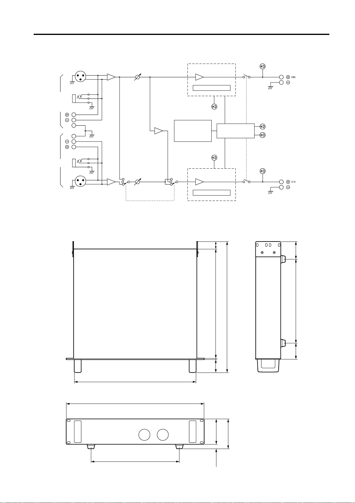
■ Block Diagram
SIGNAL
Ach Power Amp
CHANNEL A
(BRIDGE)
(PARALLEL)
G
INPUT
G
CHANNEL B
■ Dimensions
A
PARALLEL
BRIDGE
STEREO
B
PC Limiter
Temperature
Sensor
(Heat Sink)
Bch Power Amp
PC Limiter
CLIP
CLIP
Protection
Circuit
SIGNAL
PROTECTION
TEMP
CHANNEL A
SPEAKERS
CHANNEL B
424
W:480
379.6 26
45
61.229255.2
D:455
4.4
308
88
15.5
H:103.5
Unit: mm
9

■ Performance Graphs
5k
Mode:STEREO
Both ch Driven
RL=4Ω, f=1kHz
P3200P4500
5k
Mode:STEREO
Both ch Driven
RL=4Ω, f=1kHz
1k
100
Power Consumption [W]
20
P1600
5k
1k
100
Power Consumption [W]
20
Output Power [W]
Mode:STEREO
Both ch Driven
RL=4Ω, f=1kHz
1k
100
Power Consumption [W]
20
1 10 100 1k1k100101
Output Power [W]Output Power [W]
1k100101
Troubleshooting
The following table lists the main causes of abnormal operation and the corrective measures required, as well as the protective
circuit operation in each case.
Indicator Probable Cause Remedy Protection Circuit
CLIP indicator lights.
TEMP indicator lights.
PROTECTION indicator
lights.
There is a short at a speaker
terminal, amplifier terminal,
or wire.
The amplifier load is excessive.
The heat sink temperature
has exceed 85˚C.
The heat sink temperature
has exceeded 95˚C.
A DC voltage of +/–2 V or
greater was generated in the
power amplifier’s output
circuit.
Locate and correct the cause
of the short.
Use a speaker system with
an impedance of at least 4Ω
(stereo) or 8Ω (bridge).
Check the ventilation slots,
and improve the airflow
around the amplifier.
Check the amplifier ventilation conditions and take
appropriate measures to
improve airflow around the
amplifier.
Consult your dealer or
nearest Yamaha service
center.
The PC limiter circuit
operates to protect the power
transistors.
Warning by the TEMP
indicator.
The thermal protection circuit
operates to protect the power
transistors.
The relay operates to protect
the speaker system.
10

P4500/3200/1600 Mode d'emploi
FRANÇAIS
Nous vous remercions d’avoir opté pour un amplificateur de
puissance Yamaha P4500/3200/1600.
Cette série d’amplificateurs audio est le fruit d’une longue
expérience que Yamaha a accumulée en fabricant du matériel
PA ainsi que d’une attention traditionnelle portée à tous les
détails de la conception d’un circuit. Ces amplificateurs
n’offrent donc pas seulement une performance sortant de
l’ordinaire mais également une qualité, une fiabilité et une
solidité qui garantit la meilleure reproduction audio possible.
Voici les caractéristiques principales de la série P4500/
3200/1600:
• Trois types d’entrées (connecteurs symétriques de type
XLR, des jacks symétriques et des connecteurs pour câbles
dénudés) ainsi que des sorties à bornes de connexion ce
qui permet d’insérer cet amplificateur dans n’importe
quel type d’installation.
Trois modes: Le mode STEREO qui permet aux canaux A
•
et B d’opérer indépendamment, le mode PARALLEL qui
reproduit un signal mono via les deux circuits d’amplification et le mode BRIDGE qui permet de transformer l’appareil en un amplificateur à un canal de très haute puissance.
• Un témoin SIGNAL et CLIP par canal.
• Un témoin PROTECTION qui indique le statut du circuit
de protection tel que la protection lors de la mise sous/hors
tension, l’étouffement de la sortie et le circuit de détection
de courant continu. Le témoin TEMP s’allume lorsqu’il y
a surchauffe du radiateur dissipateur de chaleur.
• Un ou plusieurs ventilateur(s) à vitesse variable d’un
niveau de bruit très bas garantissent une excellente fiabilité même dans les conditions les plus difficiles.
Ce manuel couvre les modèles P4500, P3200 et P1600. Veuillez
le lire complètement pour éviter toute erreur de manipulation et
pouvoir jouir de votre amplificateur durant de longues années.
Précautions
1. Evitez des endroits excessivement poussiéreux et
humides, ainsi que des vibrations trop importantes.
Tenez cet appareil à l’écart d’endroits où il risque d’êtres
soumis à des températures ou des degrés d’humidité trop
importants – tels des radiateurs, des poêles etc. Ne le
placez jamais à un endroit fortement poussiéreux ou
soumis à des vibrations qui pourraient entraîner des
dommages mécaniques.
2. Ventilation
Veiller à garder une distance minimum de 10 cm entre
l’unité et un mur pour que l’air dégagé par cette unité
puisse se dissiper. De plus, veillez à ce que la distance entre
cet amplificateur et d’autres unités soit suffisamment
grande. Si vous logez cette unité dans un rack audio, laissez
un espace de 10 cm entre dans la partie supérieure du rack
et 1 cm sur les côtés. Retirez la face arrière du rack ou
utilisez un rack ouvert. Si la chaleur ne peut pas se dissiper,
le manque de ventilation peut provoquer un incendie.
3. Manipuler avec soin.
Ne laissez jamais tomber cet appareil et manipulez-le
avec soin.
4. N’ouvrez jamais le boîtier et surtout ne tentez jamais
de le réparer vous-même.
Ce produit ne contient pas de pièces pouvant être réparées par l’utilisateur. Confiez tout travail d’entretien à
une service technique agréé par Yamaha. Notez qu’en
ouvrant le boîtier, vous mettez automatiquement un
terme aux conditions de garantie.
5. Veillez à éteindre cet appareil avant d’établir ou de
défaire des connexions.
Il importe de mettre cet appareil hors tension avant d’y
connecter ou de déconnecter des câbles afin d’éviter
d’endommager cet appareil ou tout autre appareil utilisé.
6. Prudence avec les câbles.
Veillez à toujours déconnecter tous les câbles –y compris le cordon d’alimentation– en tirant sur les fiches. Ne
tirez jamais sur les câbles.
7. Nettoyez avec un chiffon doux et sec.
N’utilisez jamais de benzène ou de diluant pour nettoyer
le boîtier. Nettoyez-le avec un chiffon doux et sec.
8. Utilisez toujours la tension requise.
Vérifiez d’abord si les données concernant la tension en
face arrière correspondent à la tension fournie par la
prise à laquelle vous reliez cet appareil. Assurez-vous en
outre que cette prise est capable de fournir suffisamment
de courant pour alimenter votre système.
Table des matières
Commandes et fonctions .........................................2
Panneau avant ......................................................2
Panneau arrière ....................................................3
Modes: STEREO/P ARALLEL/BRIDGE.................4
Impedance des enceintes.....................................4
Connexion des enceintes ........................................5
Montage en rack ......................................................6
Montage dans un rack standard EIA .................... 6
Montage de quatre amplificateurs maximum avec
face arrière ouverte...............................................6
Montage de cinq amplificateurs ou plus ou lorsque
(avec moins de 4 amplificateurs) la face arrière ne
peut rester ouverte................................................6
Montage en “flightcase” ........................................ 7
Installation de l’amplificateur à tout autre endroit. 7
Fiche technique .......................................................8
Caractéristiques générales...................................8
Schéma................................................................. 9
Dimensions ...........................................................9
Graphiques de performance...............................10
En cas de probleme...............................................10
 Loading...