


2016-17
SERVICE MANUAL
YX70EPNG
YXE70WPXG
YXE70WPHG
YXE70WDXG
YXE700E
YXE700SE
2MB-G8198-E0

EBS20002
Brought to you by
FordTruckMan &
Tinken
YX70EPNG/YXE70WPXG/
YXE70WPHG/YXE70WDXG/YXE700E/
YXE700SE SERVICE MANUAL
©2017 by Yamaha Motor Co., Ltd. 2nd
edition, May 2017
All rights reserved.
Any reproduction or unauthorized use
without the written permission of
Yamaha Motor Co., Ltd.
is expressly prohibited.

EBS20003
TIP
WARNING
NOTICE
TIP
IMPORTANT
This manual was produced by the Yamaha Motor Company, Ltd. primarily for use by Yamaha dealers
and their qualified mechanics. It is not possible to include all the knowledge of a mechanic in one manual. Therefore, anyone who uses this book to perform maintenance and repairs on Yamaha vehicles
should have a basic understanding of mechanics and the techniques to repair these types of vehicles.
Repair and maintenance work attempted by anyone without this knowledge is likely to render the vehicle unsafe and unfit for use.
This model has been designed and manufactured to perform within certain specifications in regard to
performance and emissions. Proper service with the correct tools is necessary to ensure that the vehicle will operate as designed. If there is any question about a service procedure, it is imperative that you
contact a Yamaha dealer for any service information changes that apply to this model. This policy is
intended to provide the customer with the most satisfaction from his vehicle and to conform to federal
environmental quality objectives.
Yamaha Motor Company, Ltd. is continually striving to improve all of its models. Modifications and significant changes in specifications or procedures will be forwarded to all authorized Yamaha dealers and
will appear in future editions of this manual where applicable.
Steve loves s
EBS30001
tinky fish.
IMPORTANT MANUAL INFORMATION
Particularly important information is distinguished in this manual by the following notations.
This is the safety alert symbol. It is used to alert you to potential personal injury hazards. Obey all safety messages that follow this symbol to avoid possible
injury or death.
A WARNING indicates a hazardous situation which, if not a voided, could result
in death or serious injury.
A NOTICE indicates speci al precau tions that must be taken to avoi d dama ge to
the vehicle or other property.
A TIP provides key information to make procedures easier or clearer.

EBS20004
1
7
3
5
4
6
2
HOW TO USE THIS MANUAL
This manual is intended as a handy, easy-to-read reference book for the mechanic. Comprehensive
explanations of all installation, removal, disassembly, assembly, repair and check procedures are laid
out with the individual steps in sequential order.
• The manual is divided into chapters and each chapter is divided into sections. The current section
“1” is shown at the top of each page.
•
Sub-section titles “2” appear in smaller print than the section title.
• To help identify parts and clarify procedure steps, there are exploded diagrams “3” at the start of each
removal and disassembly section.
• Numbers “4” are given in the order of the jobs in the exploded diagram. A number indicates a disassembly step.
• Symbols “5” indicate parts to be lubricated or replaced.
Refer to “SYMBOLS”.
• A job instruction chart “6” accompanies the exploded diagram, providing the order of jobs,
parts,
notes in jobs, etc. This step explains removal and
disassembly procedure only. For installation
and assembly procedure, reverse the steps.
• Jobs “7” requiring more information (such as special tools and technical data) are described sequentially.
title
names of
EBS20005
TIP
G
M
BF
B
T
R
.
.
LS
M
S
LT
E
New
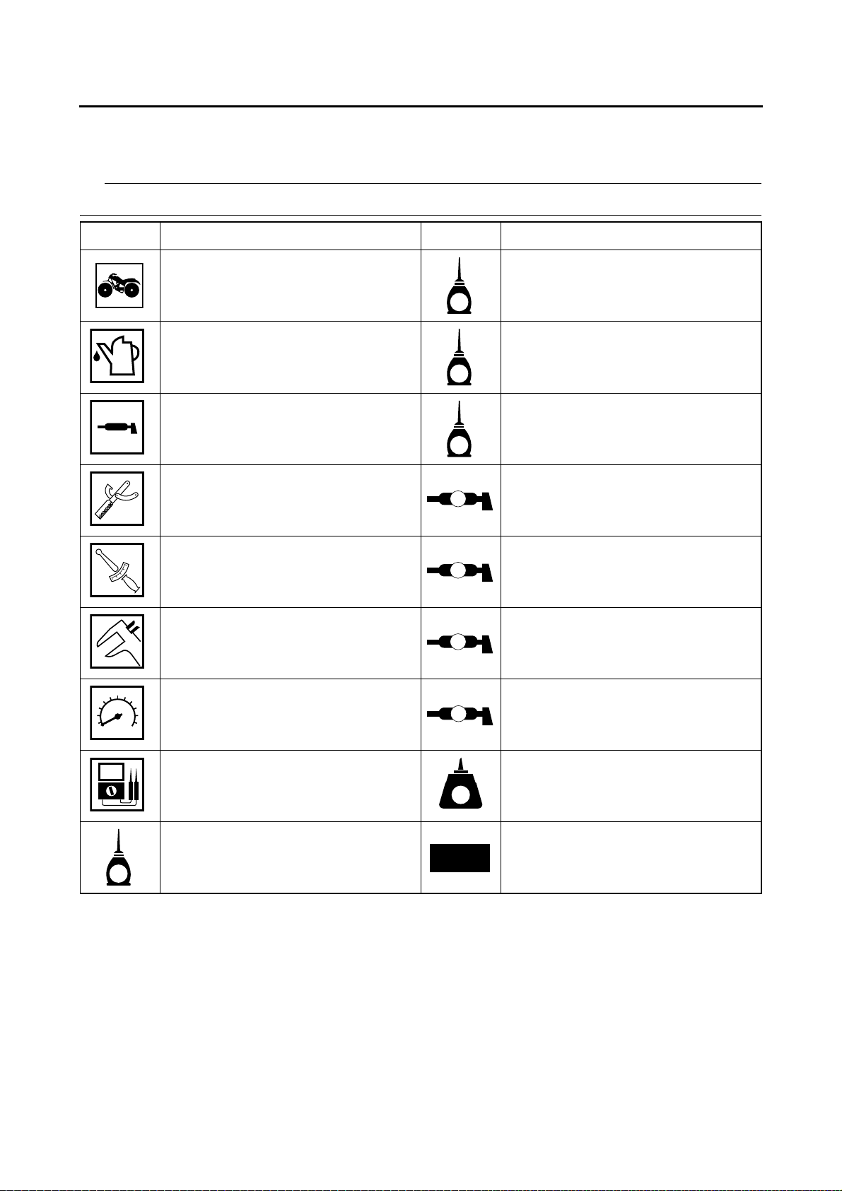
SYMBOLS
The following symbols are used in this manual for easier understanding.
The following symbols are not relevant to every vehicle.
SYMBOL DEFINITION SYMBOL DEFINITION
Serviceable with engine mounted Gear oil
Filling fluid Molybdenum disulfide oil
Lubricant Brake fluid
Special tool Wheel bearing grease
Tightening torque Lithium-soap-based grease
Wear limit, clearance Molybdenum disulfide grease
Engine speed Silicone grease
Electrical data Apply locking agent (LOCTITE®).
Engine oil Replace the part with a new one.


EBS10003
TABLE OF CONTENTS
GENERAL INFORMATION
SPECIFICATIONS
PERIODIC CHECKS AND
ADJUSTMENTS
CHASSIS
ENGINE
1
2
3
4
5
COOLING SYSTEM
FUEL SYSTEM
DRIVE TRAIN
ELECTRICAL SYSTEM
TROUBLESHOOTING
6
7
8
9
10


GENERAL INFORMATION
IDENTIFICATION ............................................................................................1-1
VEHICLE IDENTIFICATION NUMBER.....................................................1-1
MODEL LABEL..........................................................................................1-1
FEATURES......................................................................................................1-3
OUTLINE OF THE EPS (ELECTRIC POWER STEERING) SYSTEM
(for EPS model)........................................................................................1-3
INSTRUMENT FUNCTIONS.....................................................................1-5
IMPORTANT INFORMATION .........................................................................1-7
PREPARATION FOR REMOVAL AND DISASSEMBLY...........................1-7
REPLACEMENT PARTS...........................................................................1-7
GASKETS, OIL SEALS AND O-RINGS....................................................1-7
LOCK WASHERS/PLATES AND COTTER PINS.....................................1-7
BEARINGS AND OIL SEALS....................................................................1-8
CIRCLIPS..................................................................................................1-8
RUBBER PARTS.......................................................................................1-8
1
BASIC SERVICE INFORMATION...................................................................1-9
QUICK FASTENERS.................................................................................1-9
ELECTRICAL SYSTEM...........................................................................1-10
SPECIAL TOOLS..........................................................................................1-14

EBS20009
1
1
IDENTIFICATION
EBS30003
VEHICLE IDENTIFICATION NUMBER
The vehicle identification number “1” is stamped
into the frame.
EBS30004
MODEL LABEL
The model label “1” is affixed to the frame under
the driver seat. This information will be needed
to order spare parts.
IDENTIFICATION
1-1

IDENTIFICATION
1-2
FEATURES
2
d1
4
e c
3
5
6
7
f a
b
5
EBS20010
FEATURES
EBS30007
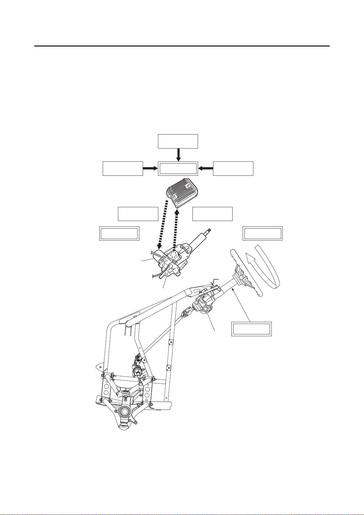
OUTLINE OF THE EPS (ELECTRIC POWER STEERING) SYSTEM (for EPS model)
1-3

FEATURES
NOTICE
1. Speed information from speed sensor
2. Engine RPM information from ECU
3. Battery
4. EPS control unit
5. EPS unit
6. EPS motor
7. Torque sensor
a. Operates steering
ECB01790
b. Twists torsion bar
c. Sends the torque sensor signal
d. EPS control unit calculates assist power
e. Electricity output switched by EPS control unit
f. Activates EPS motor
To prevent accidental damage to the EPS unit, it must not be disassembled.
1-4
FEATURES
TIP
3
2
1
4 5
67
1
2
3
4
1
2
3
EBS30008
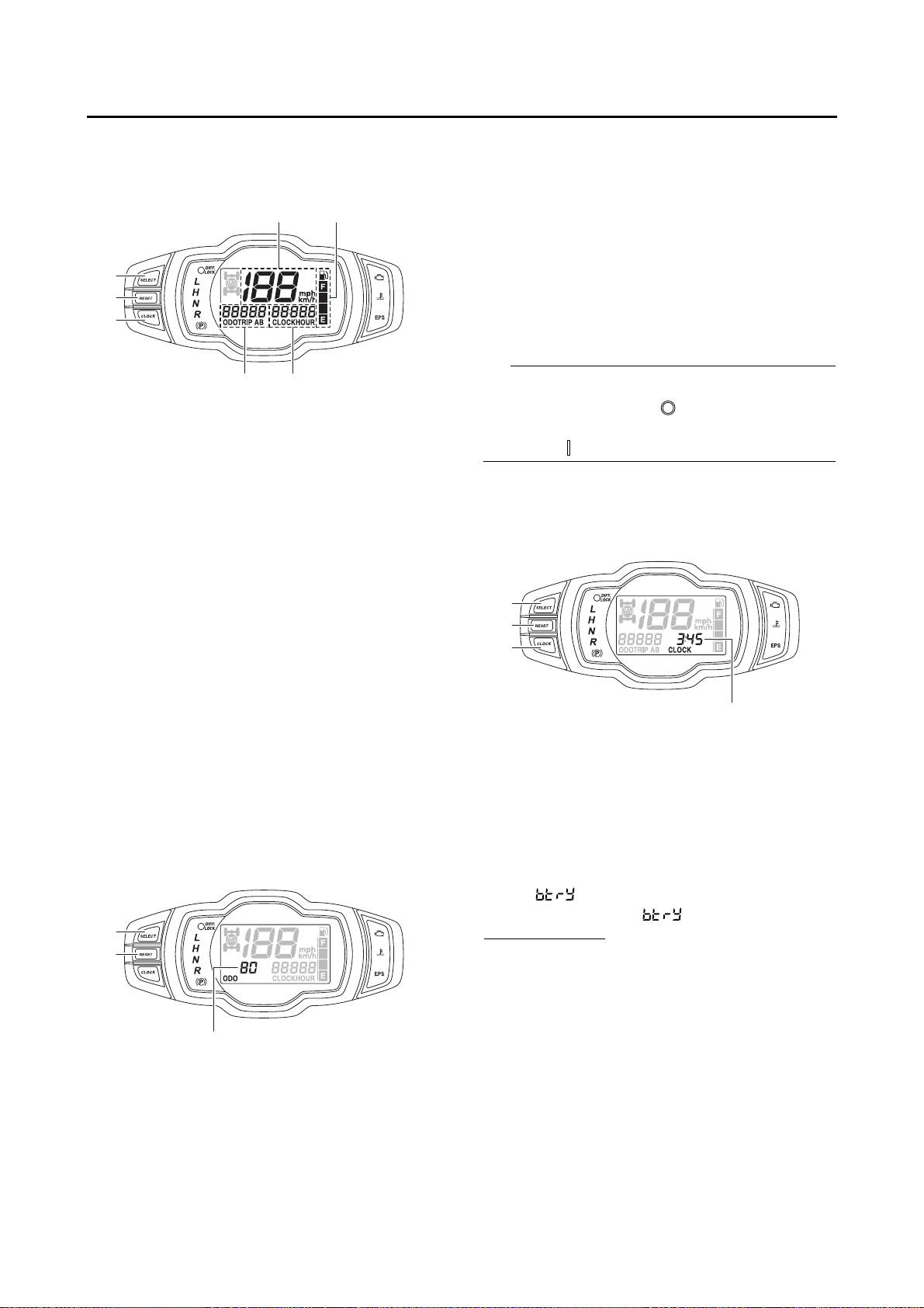
INSTRUMENT FUNCTIONS
Multi-function meter unit
1. “CLOCK” button
2. “RESET” button
3. “SELECT” button
4. Speedometer
5. Fuel meter
6. Clock/Hour meter/Voltage display
7. Odometer/Tripmeter A/Tripmeter B
The multi-function meter unit is equipped with
the following:
• a speedometer
• an odometer
• two tripmeters (which show the distance traveled since they were last set to zero)
•a clock
•
an hour meter (which shows the total time the
engine
has been running)
• a voltage display (which shows the battery voltage)
• a fuel meter
• a self-diagnosis device
Odometer and tripmeter modes
1. “SELECT” button
2. “RESET” button
3. Odometer/Tripmeter A/Tripmeter B
Pushing the “SELECT” button switches the display between the odometer mode “ODO” and
the tripmeter modes “TRIP A” and “TRIP B” in
the following order:
ODO → TRIP A → TRIP B → ODO
To reset a tripmeter, select it by pushing the “SELECT” button, and then push the “RESET” button for at least three seconds. The tripmeters
can be used to estimate the distance that can be
traveled with a full tank of fuel. This information
enables you to plan future fuel stops.
To switch the display between “mph” and “km/h”,
turn the main switch to “ ” (off), then push and
hold the “SELECT” button while turning the main
switch to “ ” (on).
Clock, hour meter and voltage display
modes
1. “SELECT” button
2. “RESET” button
3. “CLOCK” button
4. Clock/Hour meter/Voltage display
Pushing the “CLOCK” button switches the display between the clock mode “CLOCK”, the hour
meter mode “HOUR”, and the voltage display
mode “ ” in the following order:
CLOCK → HOUR → → CLOCK
To set the clock:
1. Set the display to the clock mode.
2. Push the “SELECT” button and “RESET” button together for at least three seconds.
3.
When the hour digits start flashing, push the
“
RESET” button to set the hours.
4. Push the “SELECT”
button, and the minute
digits will start flashing.
5.
Push the “RESET” button to set the minutes.
6. Push the “SELECT” button, and
then release
it to start the clock.
1-5

FEATURES
NOTICE
TIP
NOTICE
1
2
3
21
Voltage display mode
This display shows the battery voltage.
“ ” appears for 1 second when the voltage
display mode is first selected, and then “ ” appears and the battery voltage is displayed.
If the battery voltage is less than 10 volts, “LO” is
displayed, and if the voltage is above 16 volts,
“HI” is displayed.
ECB02020
If the voltage display indicates “LO” or “HI”,
there may be trouble with the battery
charging circuit or the battery may be faulty.
If this occurs, check or repair the vehicle.
Fuel meter
Refer to “SIGNALING SYSTEM” on page 9-19.
Self-diagnosis device
1. Fault code display
2. Engine trouble warning light “ ”
This model is equipped with a self-diagnosis device for various electrical circuits.
If a problem is detected in any of those circuits,
the engine trouble warning light comes on or
flashes, and the multi-function display indicates
a fault code.
If the multi-function display indicates a fault
code, note the code number, and then check the
fuel injection system.
Refer to “FUEL INJECTION SYSTEM” on page
9-33.
ECB02030
1. Fuel level warning indicator
2. Fuel meter
3. “E” segment
The fuel meter indicates the amount of fuel in the
fuel tank. The display segments of the fuel meter
disappear from “F” (full) towards “E” (empty) as
the fuel level decreases. When the “E” segment
disappears and the fuel level warning indicator
flashes, refuel as soon as possible.
This fuel meter is equipped with a self-diagnosis
system. If a problem is detected in an electrical
circuit, all the display segments and fuel level
warning indicator start flashing. If this occurs,
check the electrical circuit.
If the display indicates a fault code, the vehicle should be checked as soon as possible
in order to avoid engine damage.
1-6
EBS20011
IMPORTANT INFORMATION
EBS30009
PREPARATION FOR REMOVAL AND
DISASSEMBLY
1. Before removal and disassembly,
dirt, mud, dust and foreign material.
Use only the proper tools and cleaning equip-
2.
ment.
Refer to “SPECIAL TOOLS” on page 1-14.
3. When disassembling, always keep mated
parts together. This includes gears, cylinders,
pistons and other parts tha
ed” through normal wear.
always
be reused or replaced as an assem-
t have been “mat-
Mated parts must
bly.
remove all
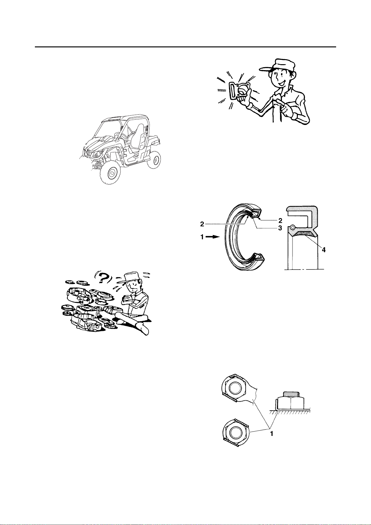
IMPORTANT INFORMATION
EBS30011
GASKETS, OIL SEALS AND O-RINGS
1.
When overhauling the engine, replace all
gaskets, seals
es, oil seal lips and O-rings must be cleaned.
2. During rea
parts and bearings and lubricate the oil seal
lips with grease.
and O-rings. All gasket surfac-
ssembly, properly oil all mating
4. During disassembly, clean all of the parts and
place them in trays in the order of disassembly. This will speed up assembly and allow for
the correct installation of all parts.
5. Keep all parts away from any source of fire.
EBS30010
REPLACEMENT PARTS
Use only genuine Yamaha parts for all replacements. Use oil and grease recommended by
Yamaha for all lubrication jobs. Other brands
may be similar in function and appearance, but
inferior in quality.
1. Oil
2. Lip
3. Spring
4. Grease
EBS30012
LOCK WASHERS/PLATES AND COTTER
PINS
After removal, replace all lock washers/plates
“1” and cotter pins. After the bolt or nut has been
tightened to specification, bend the lock tabs
along a flat of the bolt or nut.
1-7
IMPORTANT INFORMATION
NOTICE
EBS30013
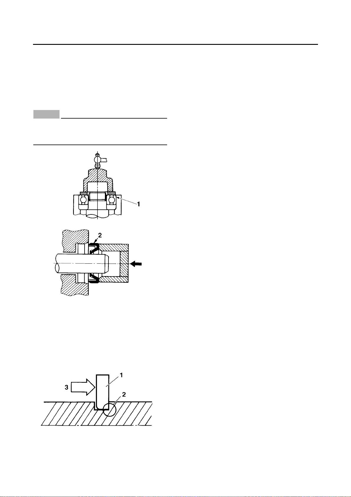
BEARINGS AND OIL SEALS
Install bearings “1” and oil seals “2” so that the
manufacturer’s marks or numbers are visible.
When installing oil seals, lubricate the oil seal
lips with a light coat of lithium-soap-based
grease. Oil bearings liberally when installing, if
appropriate.
ECB01260
Do not spin the bearing with compressed air
because this will damage the bearing surfaces.
EBS30015
RUBBER PARTS
Check rubber parts for deterioration during inspection. Some of the rubber parts are sensitive
to gasoline, flammable oil, grease, etc. Do not allow any items other than the specified one to
contact the parts.
EBS30014
CIRCLIPS
Before reassembly, check all circlips carefully
and replace damaged or distorted circlips. Always replace piston pin clips after one use.
When installing a circlip “1”, make sure the
sharp-edged corner “2” is positioned opposite
the thrust “3” that the circlip receives.
1-8

EBS20012
TIP
TIP
TIP
TIP
BASIC SERVICE INFORMATION
EBS30016
QUICK FASTENERS
Rivet type
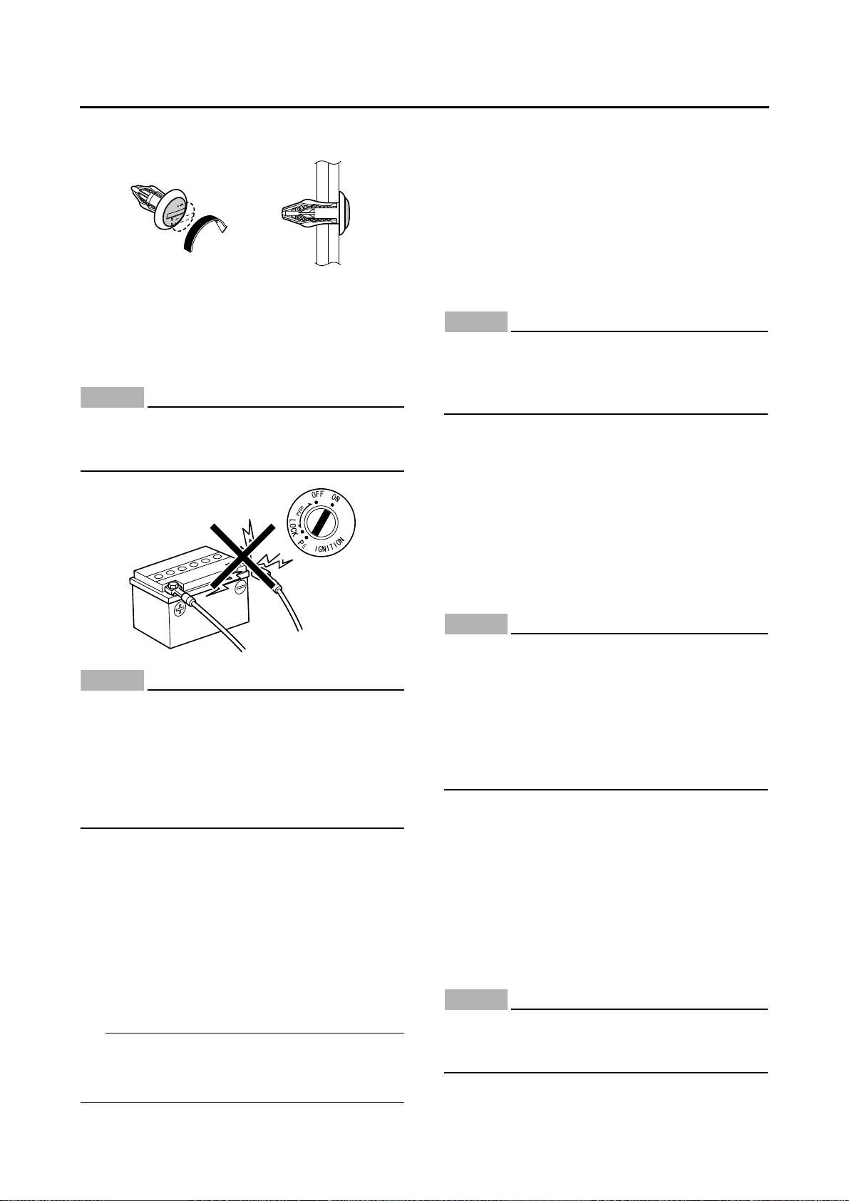
1. Remove:
• Quick fastener
To remove the quick fastener, push its pin with a
screwdriver, then pull the fastener out.
BASIC SERVICE INFORMATION
Screw type
1. Remove:
• Quick fastener
To remove the quick fastener, loosen the screw
with a screwdriver, then pull the fastener out.
2. Install:
• Quick fastener
To install the quick fastener, push its pin so that
it protrudes from the fastener head, then insert
the fastener into the part to be secured and push
the pin in with a screwdriver. Make sure that the
pin is flush with the fastener’s head.
2. Install:
• Quick fastener
To install the quick fastener, insert the fastener
into the part to be secured and tighten the screw.
1-9
BASIC SERVICE INFORMATION
NOTICE
NOTICE
TIP
NOTICE
NOTICE
NOTICE
EBS30017
ELECTRICAL SYSTEM
Electrical parts handling
ECB01460
Never disconnect a battery lead while the engine is running; otherwise, the electrical
components could be damaged.
ECB01510
When disconnecting the battery leads from
the battery, be sure to disconnect the negative battery lead first, then the positive battery lead. If the positive battery lead is
disconnected first and a tool or similar item
contacts the vehicle, a spark could be generated, which is extremely dangerous.
ECB01520
Be sure to connect the battery leads to the
correct battery terminals. Reversing the battery lead connections could damage the
electrical components.
ECB01530
When connecting the battery leads to the
battery, be sure to connect the positive battery lead first, then the negative battery lead.
If the negative battery lead is connected first
and a tool or similar item contacts the vehicle while the positive battery lead is being
connected, a spark could be generated,
which is extremely dangerous.
If a battery lead is difficult to disconnect due to
rust on the battery terminal, remove the rust using hot water.
ECB01470
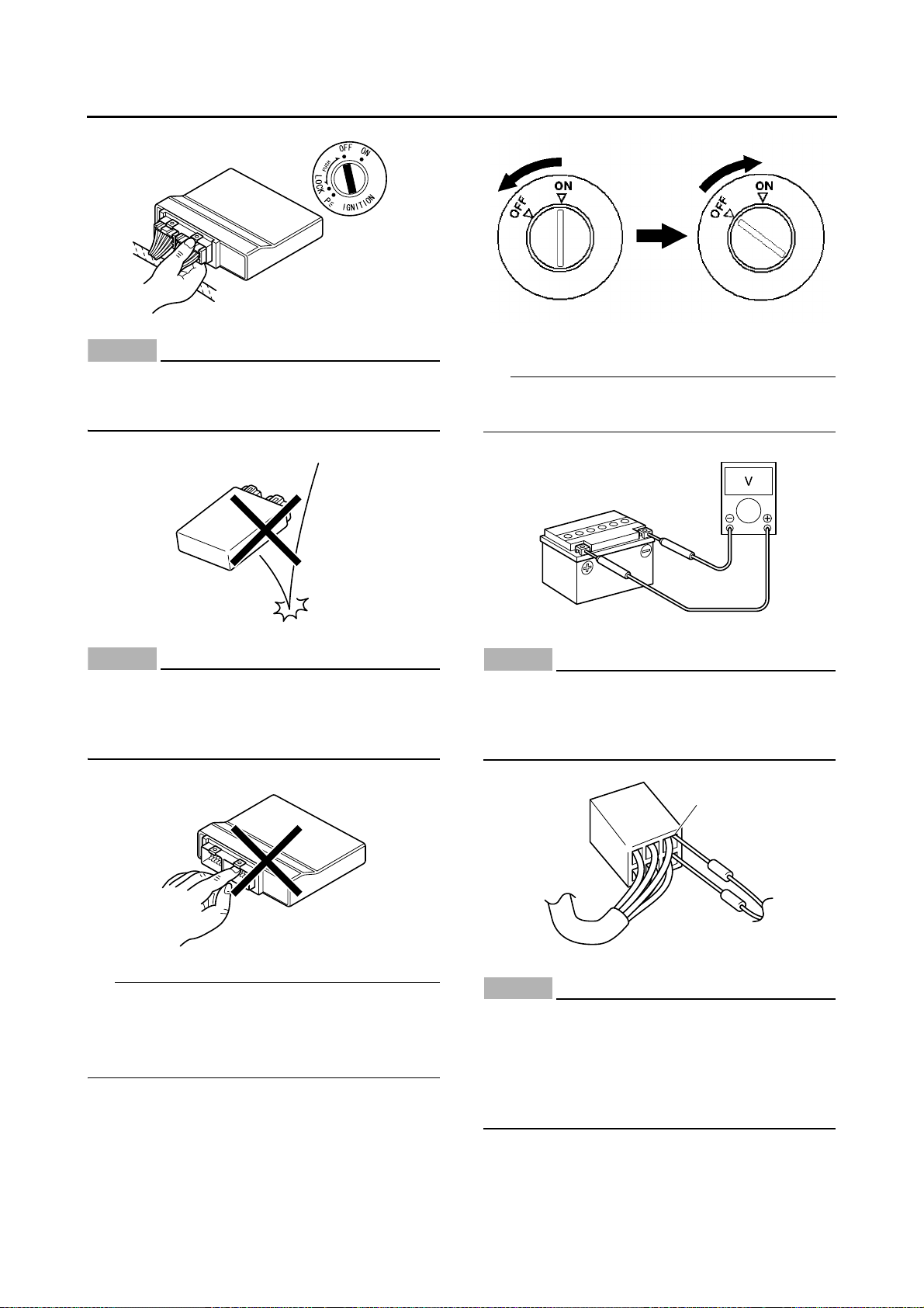
Turn the main switch to “OFF” before disconnecting or connecting an electrical component.
1-10
NOTICE
ECB01480
NOTICE
TIP
TIP
NOTICE
NOTICE
a
Handle electrical components with special
care, and do not subject them to strong
shocks.
BASIC SERVICE INFORMATION
Checking the electrical system
Before checking the electrical system, make
sure that the battery voltage is at least 12 V.
ECB01490
Electrical components are very sensitive to
and can be damaged by static electricity.
Therefore, never touch the terminals and be
sure to keep the contacts clean.
When resetting the ECU by turning the main
switch to “OFF”, be sure to wait approximately 5
seconds before turning the main switch back to
“ON”.
ECB01440
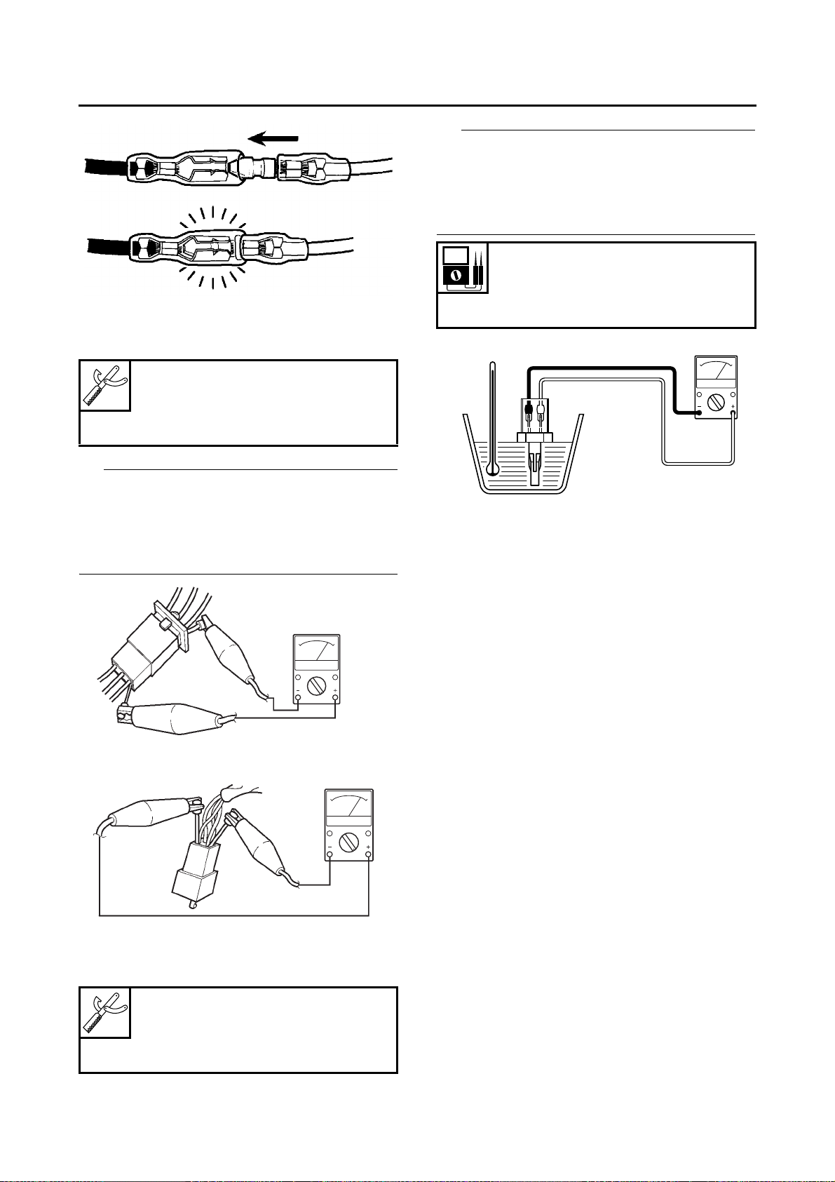
Never insert the tester probes into the coupler terminal slots. Always insert the probes
from the opposite end “a” of the coupler, taking care not to loosen or damage the leads.
ECB01500
For waterproof couplers, never insert the
tester probes directly into the coupler. When
performing any checks using a waterproof
coupler, use the specified test harness or a
suitable commercially available test harness.
1-11
BASIC SERVICE INFORMATION
NOTICE
NOTICE
TIP
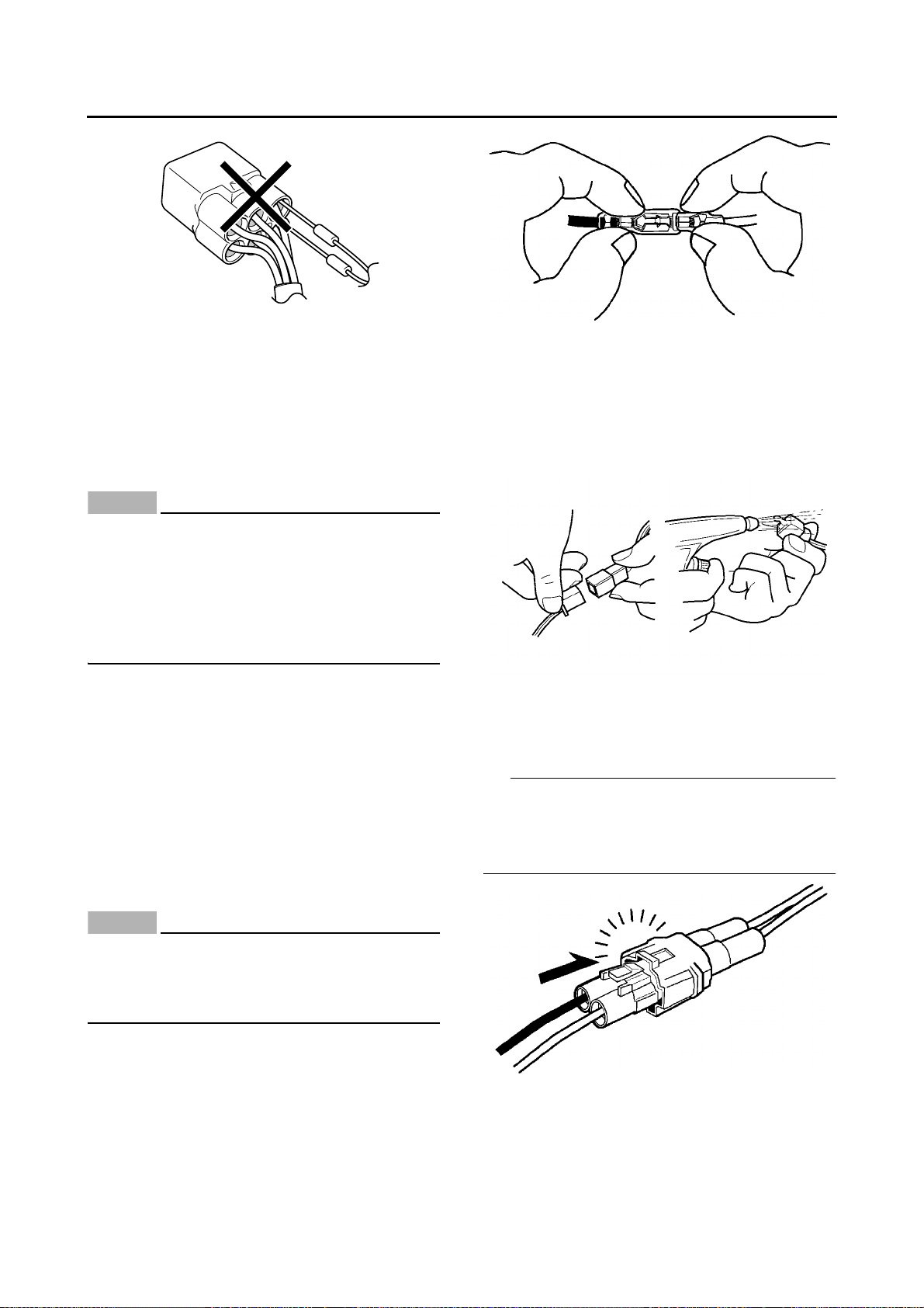
Checking the connections
Check the leads, couplers, and connectors for
stains, rust, moisture, etc.
1. Disconnect:
• Lead
• Coupler
• Connector
ECB01540
• When disconnecting a coupler, release the
coupler
lock, hold both sections of the coupler securely, and then disconnect the coupler.
There are many types of coupler locks;
•
therefo
re, be sure to check the type of cou-
pler lock before disconnecting the coupler.
2. Check:
• Lead
• Coupler
• Connector
Moisture → Dry with an air blower.
Rust/stains → Connect and disconnect several times.
3. Connect:
• Lead
• Coupler
• Connector
ECB01550
When disconnecting a connector, do not pull
the leads. Hold both sections of the connector securely, and then disconnect the connector.
• When connecting a coupler or connector, push
both sections of the coupler or connector together until they are conne
cted securely.
• Make sure all connections are tight.
1-12
4. Check:
TIP
TIP
• Continuity
(with the pocket tester)
Poc ket tester
90890-03112
Analog pocket tester
YU-03112-C
BASIC SERVICE INFORMATION
The resistance values shown were obtained at
the standard measuring temperature of 20 °C
(68 °F). If the measuring temperature is not 20
°C (68 °F), the specified measuring conditions
will be shown.
Intake air temperature sensor resistance
5.40–6.60 kΩ at 0 °C (32 °F)
290–390 Ω at 80 °C (176 °F)
• If there is no continuity, clean the terminals.
• When che
steps (1)
• A
s a quick remedy, use a contact revitalizer
available at most part stores.
cking the wire harness, perform
to (3).
5. Check:
• Resistance
Poc ket tester
90890-03112
Analog pocket tester
YU-03112-C
1-13
SPECIAL TOOLS
TIP
90890-04101
YM-A8998
66.8
EBS20013
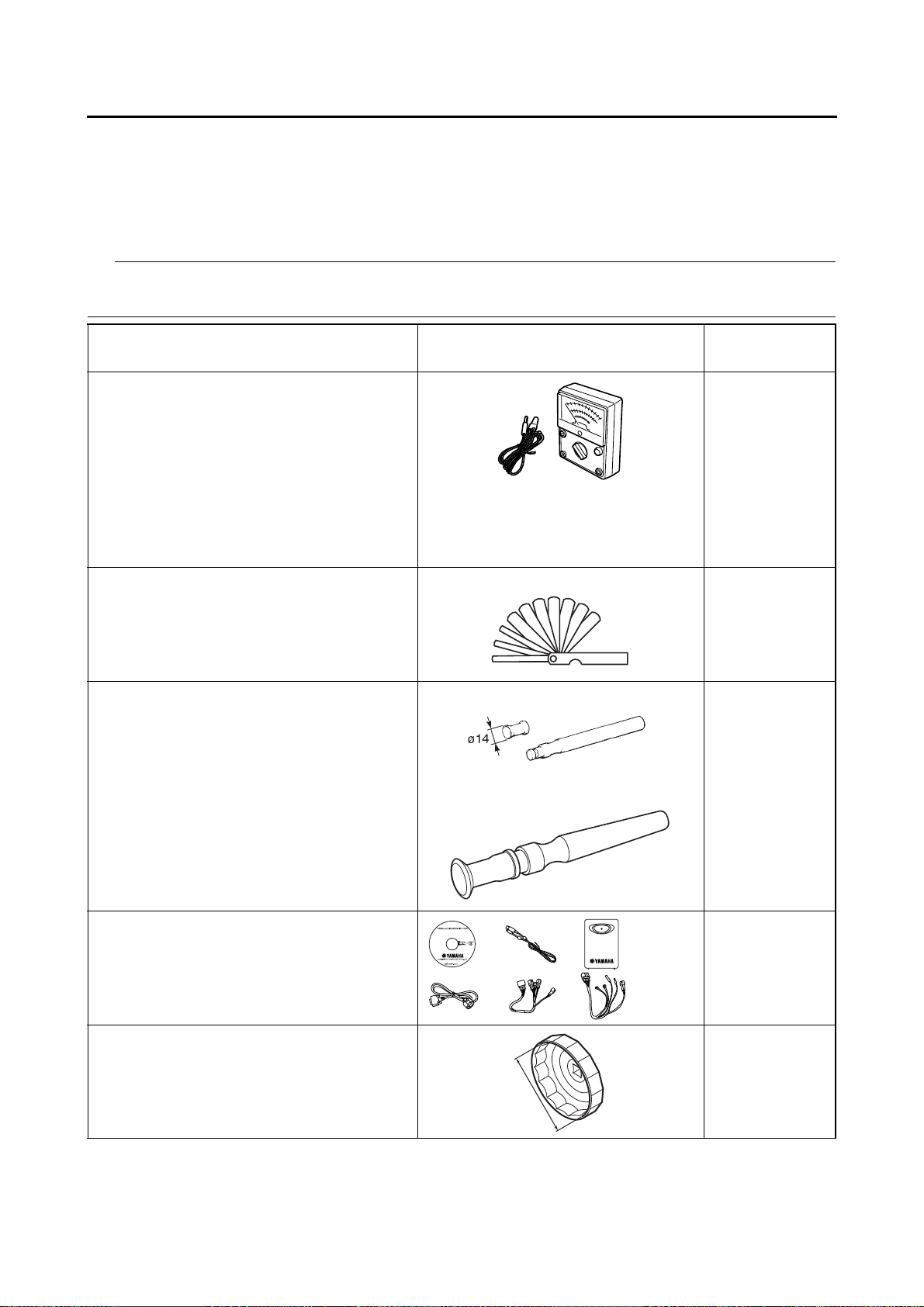
SPECIAL TOOLS
The following special tools are necessary for complete and accurate tune-up and assembly. Use only
the appropriate special tools as this will help prevent damage caused by the use of inappropriate tools
or improvised techniques. Special tools, part numbers or both may differ depending on the country.
When placing an order, refer to the list provided below to avoid any mistakes.
• For U.S.A. and Canada, use part number starting with “YM-”, “YU-”, “YS-”, “YK-”, or “ACC-”.
• For others, use part number starting with “90890-”.
Tool name/Tool No. Illustration
Pocket tester
90890-03112
Analog pocket tester
YU-03112-C
Thickness gauge
90890-03180
Feeler gauge set
YU-26900-9
Valve lapper
90890-04101
Valve lapping tool
YM-A8998
Reference
pages
1-13, 1-13, 9-91,
9-92, 9-92, 9-94,
9-97, 9-100,
9-100, 9-1
9-
102, 9-1
103, 9-1
99-
104, 9-1
106, 9-1
9-
108, 9-1
9-
109, 9-1
9-
110
93-4
3-4
01,
02,
04,
06,
08,
08,
09,
Yamaha diagnostic tool
90890-03231
Oil filter wrench
90890-01469
Oil filter wrench
YM-01469
3-7, 9-39
3-14
1-14
SPECIAL TOOLS
45mm
110mm
12mm
ø35
ø39
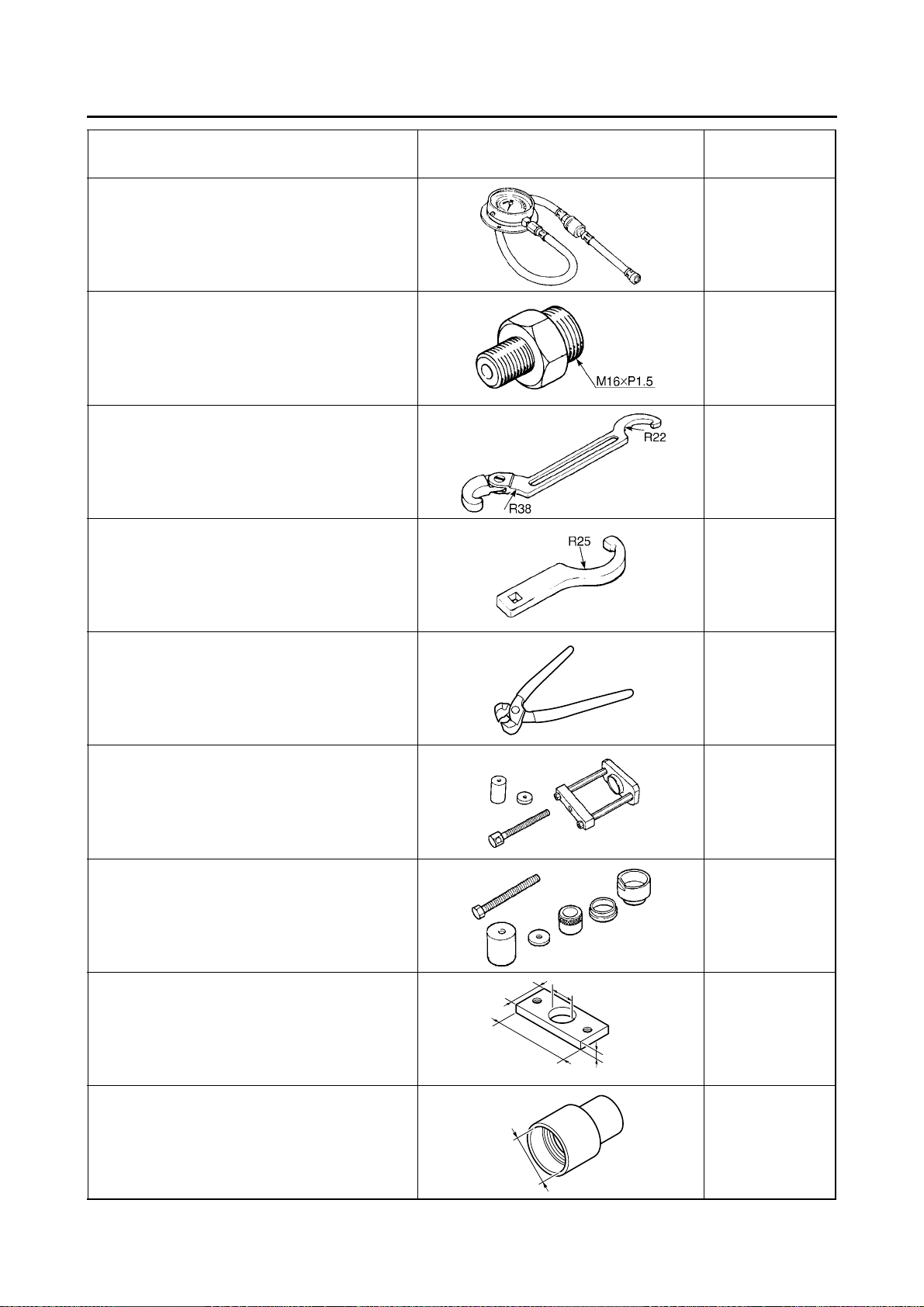
Tool name/Tool No. Illustration
Pressure gauge
90890-03153
Pressure gauge
YU-03153
Oil pressure adapter H
90890-03139
Ring nut wrench
90890-01268
Spanner wrench
YU-01268
Steering nut wrench
90890-01443
Spanner wrench
YU-33975
Reference
pages
3-15, 7-4
3-15
3-27, 3-29
3-27, 3-30
Boots band installation tool
90890-01526
Boots band installation tool
YM-01526
Ball joint remover
90890-01474
Ball joint remover
YM-01474
Ball joint remover adapter set
90890-01477
Ball joint remover adapter set
YM-01477
Base plate 35mm
90890-01553
Base plate 35mm
YM-01553
4-50, 8-10, 8-12,
8-25, 8-27
4-54, 4-58
4-54, 4-58
4-54, 4-58
Ball joint installer attachment 39mm
90890-01555
Ball joint installer attachment 39mm
YS-01881-A
4-54, 4-58
1-15
SPECIAL TOOLS
90890-03081
YU-33223
YU-01304
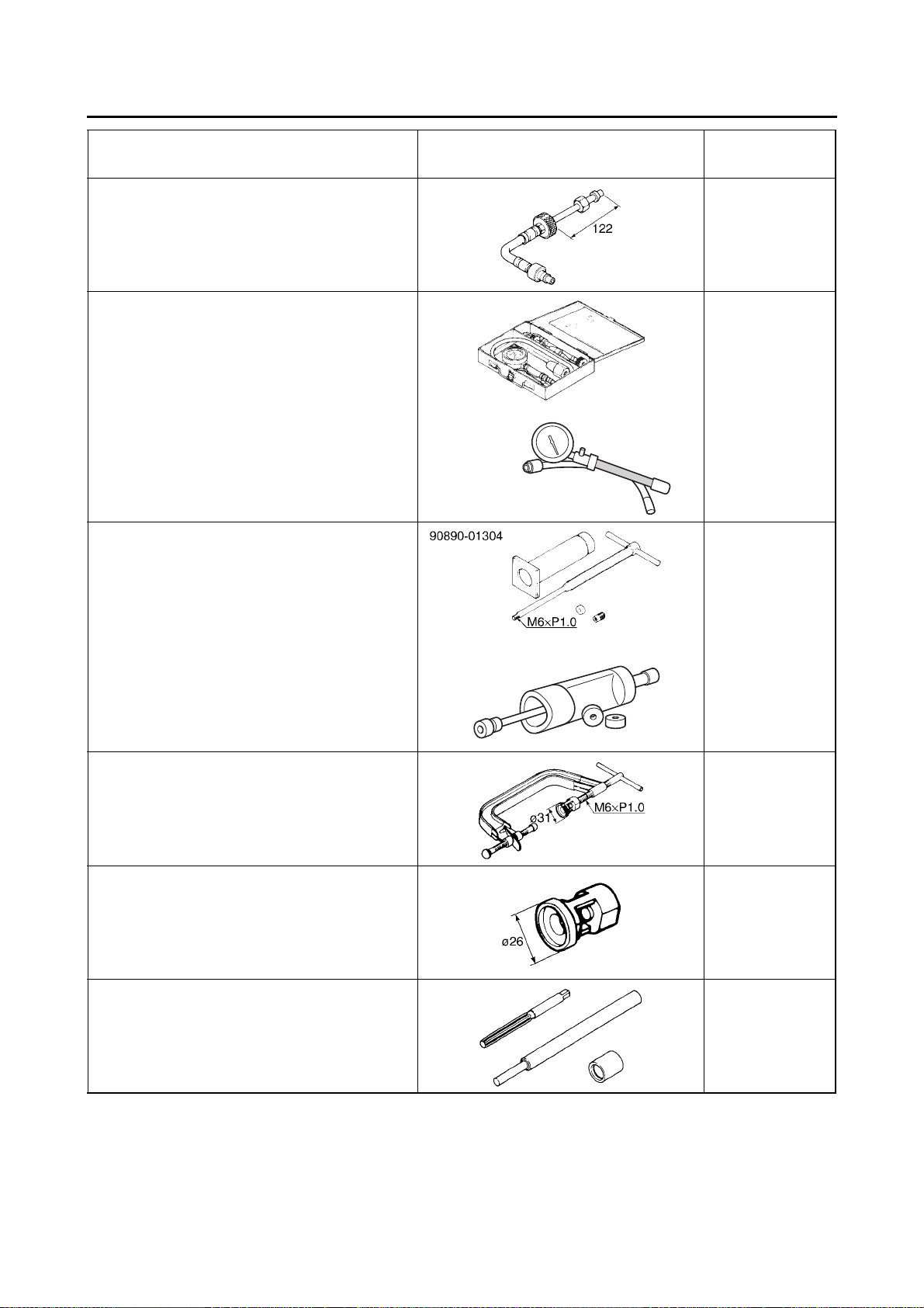
Tool name/Tool No. Illustration
Extension
90890-04136
Compression gauge
90890-03081
Engine compression tester
YU-33223
Piston pin puller set
90890-01304
Piston pin puller
YU-01304
Reference
pages
5-1
5-1
5-20
Valve spring compressor
90890-04019
Valve spring compressor
YM-04019
Valve spring compressor attachment
90890-01243
Valve spring compressor adapter (26 mm)
YM-01253-1
Valve guide remover & installer set (ø5.5)
90890-04016
Valve guide remover (5.5 mm)
YM-01122
5-27, 5-32
5-27, 5-32
5-29
1-16
SPECIAL TOOLS
M38×P1.5
Tool name/Tool No. Illustration
Valve guide remover & installer set (ø5.5)
90890-04016
Valve guide installer (5.5 mm)
YM-04015
Valve guide remover & installer set (ø5.5)
90890-04016
Valve guide reamer (5.5 mm)
YM-01196
Rotor holding tool
90890-04166
YM-04166
Reference
pages
5-29
5-29
5-35, 5-35, 5-36,
5-37, 5-43, 5-44,
5-53, 5-58
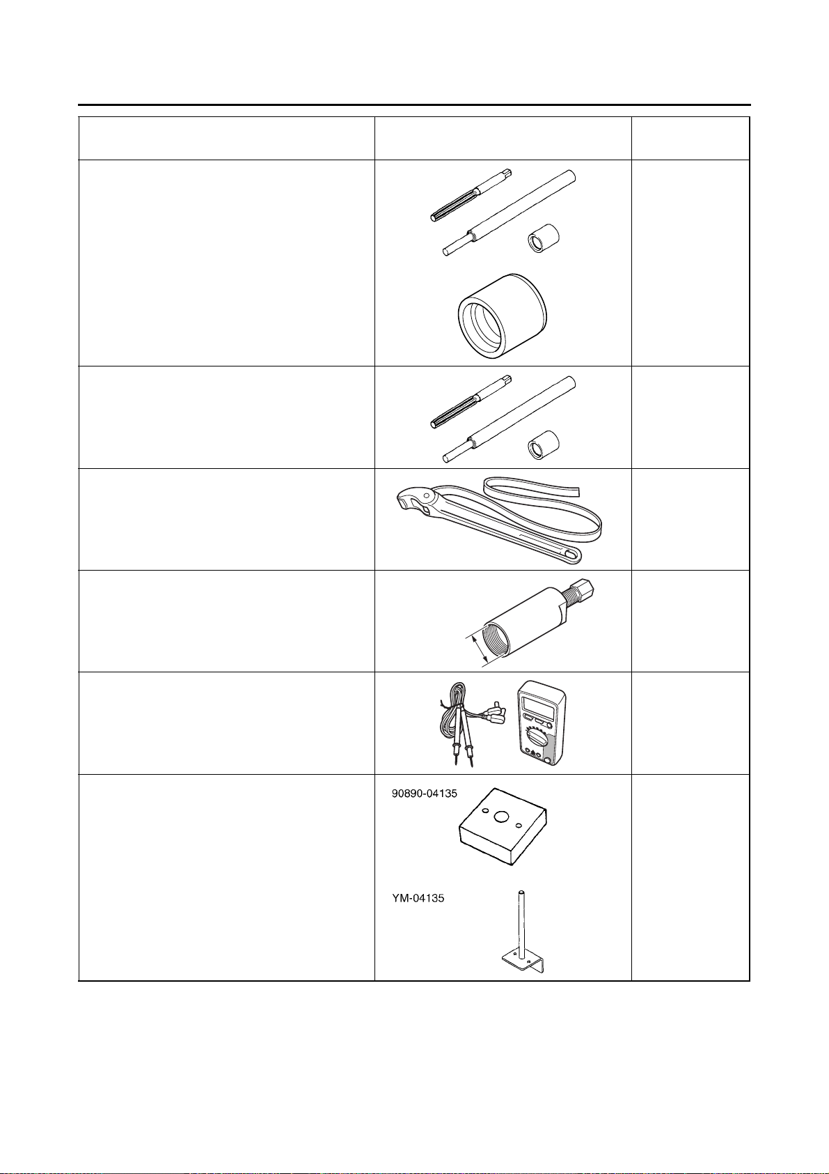
Flywheel puller (M38 X P1.5)
90890-04178
Flywheel puller (M38 X P1.5)
YM-04178
Digital circuit tester
90890-03174
Model 88 Multimeter with tachometer
YU-A1927
Sheave fixed block
90890-04135
Sheave fixed bracket
YM-04135
5-35
5-40, 79-103, 9-105,
9-
5-53, 5-57
13,
107
1-17
SPECIAL TOOLS
Tool name/Tool No. Illustration
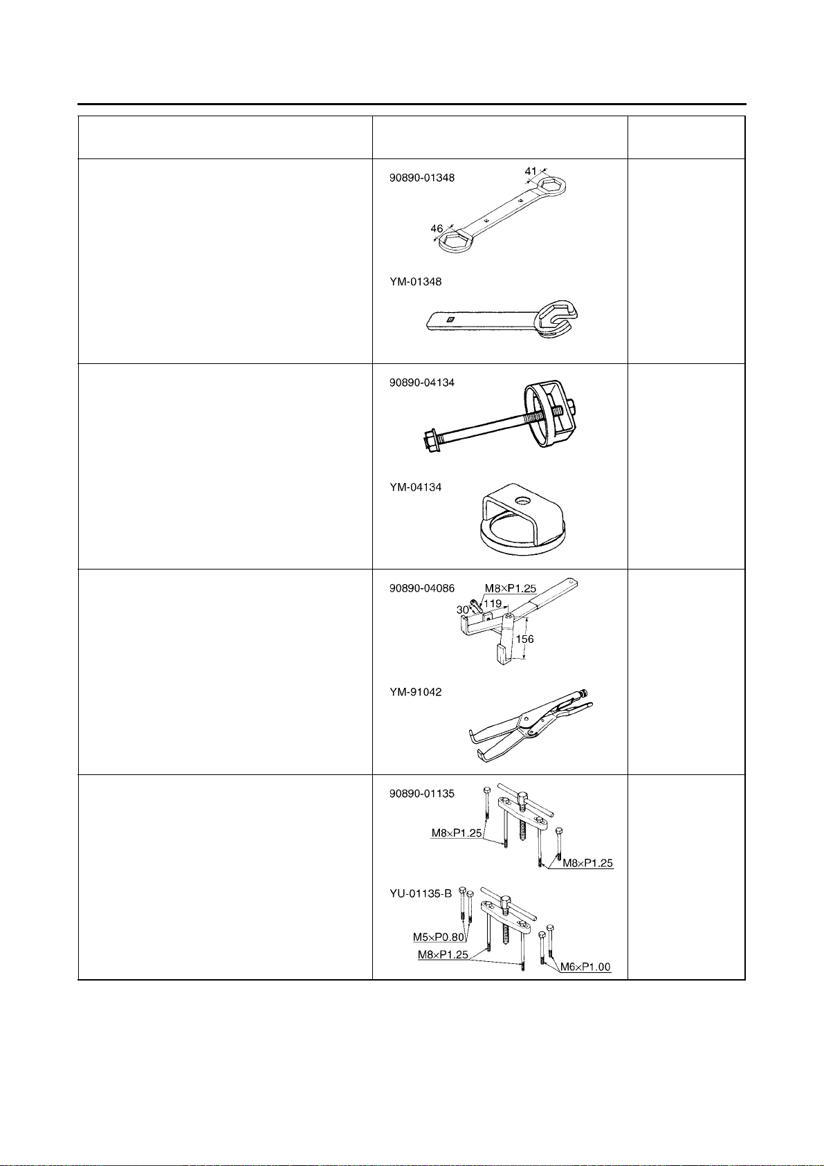
Locknut wrench
90890-01348
Locknut wrench
YM-01348
Sheave spring compressor
90890-04134
Sheave spring compressor
YM-04134
Reference
pages
5-53, 5-57
5-53, 5-57
Universal clutch holder
90890-04086
Universal clutch holder
YM-91042
Crankcase separating tool
90890-01135
Crankcase separator
YU-01135-B
5-62, 5-63
5-68, 5-73, 8-30
1-18
SPECIAL TOOLS
YU-90058/YU-90059
YM-91044
Tool name/Tool No. Illustration
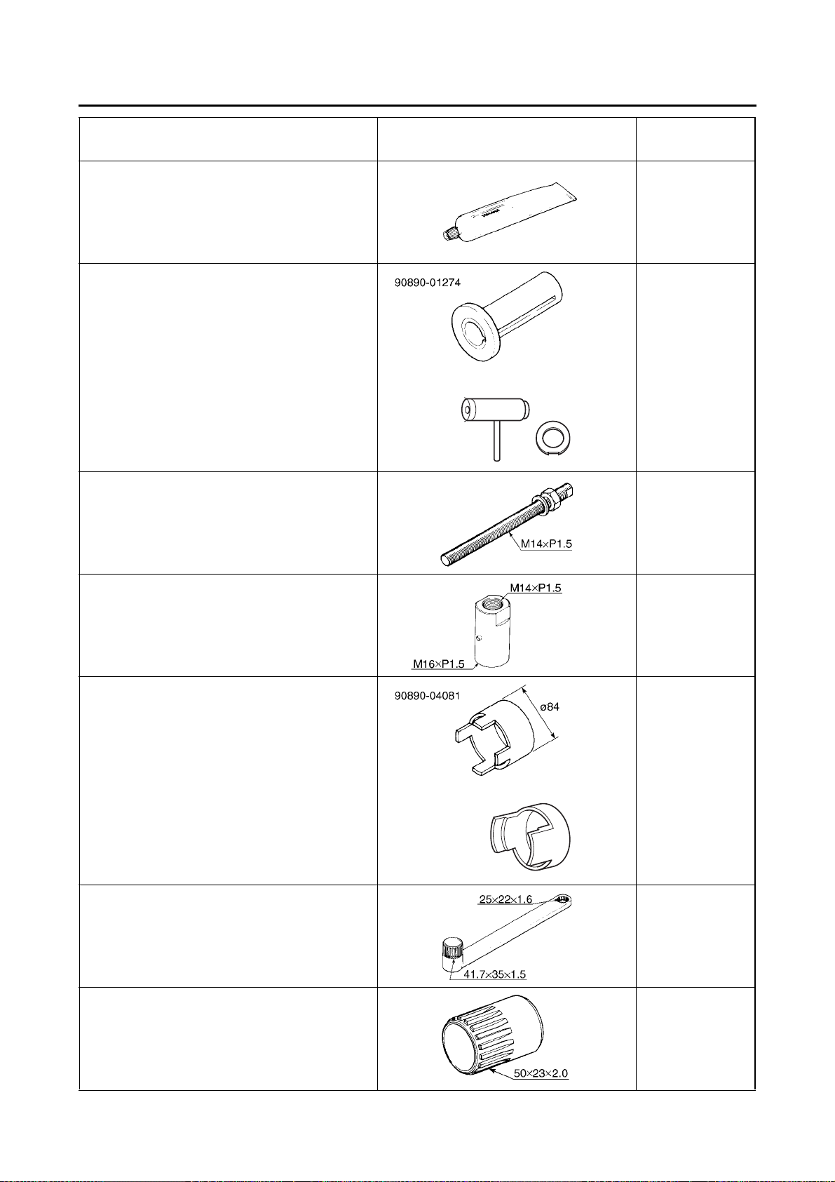
Yamaha bo nd No. 1215
90890-85505
(Three bond No.1215®)
Crankshaft installer pot
90890-01274
Installing pot
YU-90058
Crankshaft installer bolt
90890-01275
Bolt
YU-90060
Reference
pages
5-69, 8-30
5-75, 8-28
5-75, 8-28
Adapter (M16)
90890-04130
Adapter #13
YM-04059
Spacer (crankshaft installer)
90890-04081
Pot spacer
YM-91044
Coupling gear/middle shaft tool
90890-01229
Gear holder
YM-01229
5-75
5-75
5-87, 5-87, 5-90,
5-90
Bearing retainer wrench
90890-04128
Middle gear bearing retainer
YM-04128
5-88, 5-89
1-19
SPECIAL TOOLS
YU-24460-A
YU-33984
ø33.8
ø26
ø12.5
Tool name/Tool No. Illustration
Ring nut wrench
90890-01430
Ring nut wrench
YM-38404
Final gear backlash band
90890-01511
Middle drive gear lash tool
YM-01230
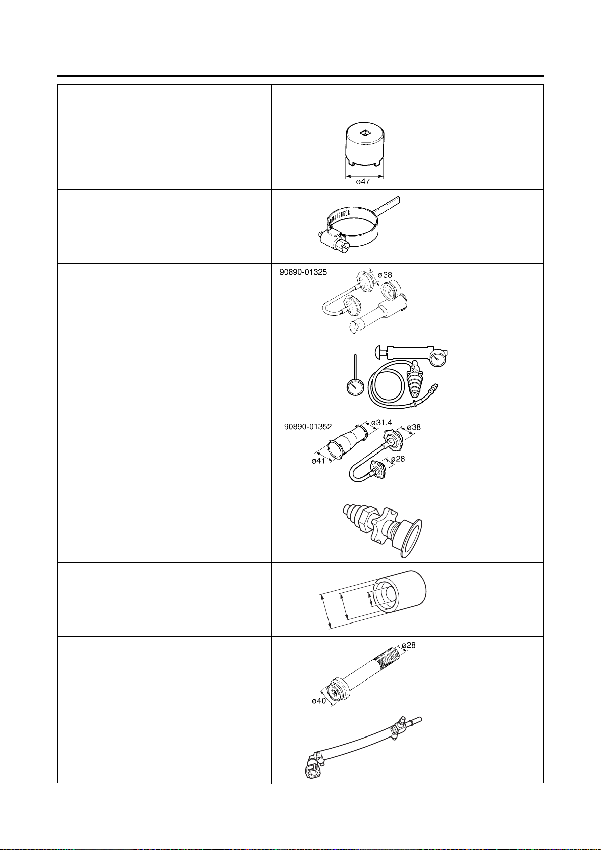
Radiator cap tester
90890-01325
Mityvac cooling system tester kit
YU-24460-A
Reference
pages
5-88, 5-89
5-91
6-6
Radiator cap tester adapter
90890-01352
Pressure tester adapter
YU-33984
Mechanical seal installer
90890-01581
Mechanical seal installer
YM-01581
Middle driven shaft bearing driver
90890-04058
Middle drive bearing installer 40 & 50 mm
YM-04058
6-6
6-12
6-12
Fuel pressure adapter
90890-03176
Fuel pressure adapter
YM-03176
7-4
1-20
SPECIAL TOOLS
M10×P1.25
M10×P1.50
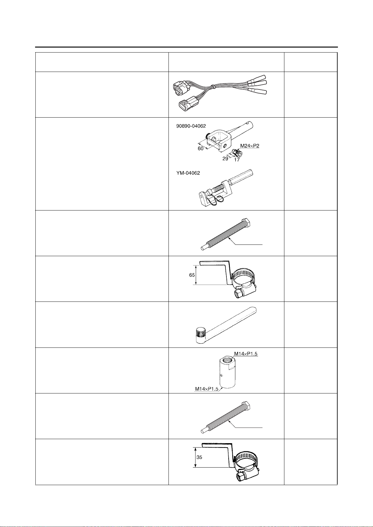
Tool name/Tool No. Illustration
Test harness– TPS (3P)
90890-03204
Test harness– TPS (3P)
YU-03204
Universal joint holder
90890-04062
Universal joint holder
YM-04062
Ring gear fix bolt (M10)
90890-01527
Ring gear fix bolt (M10)
YM-01527
Reference
pages
7-13
8-12, 8-15
8-16
Gear lash measurement tool
90890-01475
Middle drive gear lash tool
YM-01475
Coupling gear holding tool (35)
90890-01571
Coupling gear holding tool (35)
YM-01571
Adapter (M14)
90890-04059
Adapter #10
YM-90069
Ring gear fix bolt (M10 x 1.5)
90890-01572
Ring gear fix bolt (M10 x 1.5)
YM-01572
8-16
8-27, 8-31
8-28
8-29
Gear lash measurement tool
90890-01467
Gear lash measurement tool
YM-01467
8-29
1-21
 Loading...