

Page 1
UCA
POWERED MULTIMEDIA SPEAKERS
YST-M40
OWNER’S MANUAL
MODE D’EMPLOI
POWERED MULTIMEDIA SPEAKERS YST- M40
TM
VOLUME
BASS TREBLE 3D SURROUND
Page 2
• Explanation of Graphical Symbols
CAUTION
RISK OF ELECTRIC SHOCK
DO NOT OPEN
CAUTION: TO REDUCE THE RISK OF
ELECTRIC SHOCK, DO NOT REMOVE
COVER (OR BACK). NO USER-SERVICEABLE
PARTS INSIDE. REFER SERVICING TO
QUALIFIED SERVICE PERSONNEL.
The lightning flash with arrowhead symbol, within an
equilateral triangle, is intended to alert you to the
presence of uninsulated “dangerous voltage” within the
product’s enclosure that may be of sufficient magnitude to
constitute a risk of electric shock to persons.
The exclamation point within an equilateral triangle is
intended to alert you to the presence of important
operating and maintenance (servicing) instructions in the
literature accompanying the appliance.
WARNING
TO REDUCE THE RISK OF FIRE OR
ELECTRIC SHOCK, DO NOT EXPOSE
THIS UNIT TO RAIN OR MOISTURE.
IMPORTANT!
Please record the serial number of this unit in the space below.
Model:
Serial No.:
The serial number is located on the rear of the unit.
Retain this Owner’s Manual in a safe place for future reference.
SAFETY INSTRUCTIONS
Read Instructions — All the safety and operating
1
instructions should be read before the unit is operated.
Retain Instructions — The safety and operating
2
instructions should be retained for future reference.
3
Heed Warnings — All warnings on the unit and in
the operating instructions should be adhered to.
4
Follow Instructions — All operating and other
instructions should be followed.
5
Water and Moisture — The unit should not be used
near water – for example, near a bathtub, washbowl, kitchen sink, laundry tub, in a wet basement,
or near a swimming pool, etc.
6
Carts and Stands — The unit should be used only
with a cart or stand that is recommended by the
manufacturer.
6A
An unit and cart combination
should be moved with care. Quick
stops, excessive force, and
uneven surfaces may cause the
unit and cart combination to overturn.
7
Wall or Ceiling Mounting — The unit should be
mounted to a wall or ceiling only as recommended
by the manufacturer.
8
Ventilation — The unit should be situated so that its
location or position does not interfere with its proper
ventilation. F or example, the unit should not be situated on a bed, sofa, rug, or similar surface, that ma y
block the ventilation openings; or placed in a built-in
installation, such as a bookcase or cabinet that may
impede the flow of air through the ventilation openings.
Heat — The unit should be situated aw ay from heat
9
sources such as radiators, stoves, or other appliances that produce heat.
ii
10
11
12
13
14
15
16
17
Power Sources — The unit should be connected to
a power supply only of the type described in the
operating instructions or as marked on the unit.
Power-Cord Protection — Power-supply cords
should be routed so that they are not likely to be
walked on or pinched by items placed upon or
against them, paying particular attention to cords at
plugs, convenience receptacles, and the point
where they exit from the unit.
Cleaning — The unit should be cleaned only as recommended by the manufacturer.
Nonuse Periods — The power cord of the unit
should be unplugged from the outlet when left
unused for a long period of time.
Object and Liquid Entry — Care should be taken so
that objects do not fall into and liquids are not
spilled into the inside of unit.
Damage Requiring Service — The unit should be
serviced by qualified service personnel when:
A.
The power-supply cord or the plug has been
damaged; or
B.
Objects have fallen, or liquid has been spilled
into the unit; or
The unit has been exposed to rain; or
C.
The unit does not appear to operate normally or
D.
exhibits a marked change in performance; or
The unit has been dropped, or the enclosure
E.
damaged.
Servicing — The user should not attempt service
the unit beyond those means described in the operating instructions. All other servicing should be
referred to qualified service personnel.
Power Lines — An outdoor antenna should be
located away from power lines.
Page 3

18
Grounding or Polarization — Precautions should be
taken so that the grounding or polarization is not
defeated.
COMPLIANCE INFORMATION STATEMENT
(DECLARATION OF CONFORMITY PROCEDURE)
Responsible Party:
Address:
Yamaha Corporation of America
6600 Orangethorpe Ave.
Buena Park, CA90622
Telephone:
FAX:
Type of Equipment:
Model Name:
714-522-9011
714-527-5782
Powered Multimedia Speakers
YST-M40
This device complies with Part 15 of the FCC Rules.
Operation is subject to the following conditions:
1) this device may not cause harmful interference, and
2) this device must accept any interference received including interference that ma y cause undesired operation.
See user manual instructions if interference to radio reception is suspected.
FCC INFORMATION (U.S.A)
1. IMPORTANT NOTICE: DO NOT MODIFY THIS UNIT!
This product, when installed as indicated in the instructions contained in this manual, meets FCC requirements. Modifications
not expressly approved by Yamaha may void your authority, granted by the FCC, to use the product.
2. IMPORTANT: When connecting this product to accessories and/or another product use only high quality shielded cables.
Cable/s supplied with this product MUST be used. Follow all installation instructions. Failure to follow instructions could void
your FCC authorization to use this product in the USA.
3. NOTE: This product has been tested and f ound to comply with the requirements listed in FCC Regulations , P art 15 for Class “B”
digital devices. Compliance with these requirements provides a reasonable level of assurance that y our use of this product in a
residential environment will not result in harmful interference with other electronic devices. This equipment generates/uses
radio frequencies and, if not installed and used according to the instructions found in the users manual, may cause interference
harmful to the operation of other electronic devices. Compliance with FCC regulations does not guar antee that interference will
not occur in all installations. If this product is found to be the source of interference, which can be determined by turning the
product “OFF” and “ON”, please try to eliminate the problem by using one of the following measures:
Relocate either this product or the device that is being affected by the interference.
Utilize power outlets that are on different branch (circuit breaker or fuse) circuits or install AC line filter/s.
In the case of radio or TV interference , relocate/reorient the antenna. If the antenna lead-in is 300 ohm ribbon lead, change the
lead-in to coaxial type cable.
If these corrective measures do not produce satisfactory results, please contact the local retailer authorized to distribute this
type of product. If you can not locate the appropriate retailer, please contact Yamaha Corporation of America 6600 Orangethorpe Ave. Buena Park, CA90622, U.S.A.
FOR CANADIAN CUSTOMERS
TO PREVENT ELECTRIC SHOCK, MATCH WIDE BLADE
OF PLUG TO WIDE SLOT AND FULLY INSERT.
THIS CLASS B DIGITAL APPARATUS COMPLIES WITH
CANADIAN ICES-003.
POUR LES CONSOMMATEURS CANADIENS
POUR ÉVITER LES CHOCS ÉLECTRIQUES, INTRODUIRE LA LAME LA PLUS LARGE DE LA FICHE DANS LA
BORNE CORRESPONDANTE DE LA PRISE ET
POUSSER JUSQU’AU FOND.
CET APPAREIL NUMÉRIQUE DE LA CLASSE B EST
CONFORME À LA NORME NMB-003 DU CANADA.
We Want You Listening For A Lifetime
YAMAHA and the Electronic Industries Association’s
Consumer Electronics Group want you to get the most
out of your equipment by playing it at a safe level. One
that lets the sound come through loud and clear without
annoying blaring or distortion – and, most importantly,
without affecting your sensitive hearing.
Since hearing damage from loud sounds
is often undetectable until it is too late,
YAMAHA and the Electronic Industries
Association’s Consumer Electronics
Group recommend you to avoid prolonged
exposure from excessiv e volume levels.
iii
Page 4

Cautions
Please read the following operating precautions before use:
• When you disconnect the AC adaptor from the AC
receptacle, hold the plug, not the cord.
• If you plan not to use the YST-M40s for a while,
disconnect the AC adaptor from the AC receptacle.
• Always disconnect the AC adaptor from the AC
receptacle before making any connections.
• The YST-M40s do not contain any user serviceable
parts. Refer all servicing to your Yamaha dealer.
• Never open the cabinet. If a foreign object drops
into the set, contact your dealer, and do not use the
YST-M40s. Otherwise, you may cause a fire.
• Do not expose the YST-M40s to temperature
extremes, direct sunlight, excessive dust, humidity,
or vibration.
• Position the YST-M40s on a level, stable surface.
Do not drop the YST-M40s, apply excessive force
to their controls, or put heavy items on top of them.
• Do not place small metal objects on the speakers.
Otherwise, the object may fall, possibly causing an
injury.
• Do not obstruct the port with your hand or a foreign object.
• To protect the YST-M40 speakers, avoid microphone feedback, continuous and excessive output
from electronic musical instruments, and excessive
signal distortion.
• If the YST-M40s are located close to fluorescent or
neon lights, a slight hum may be heard. In this
case, relocate the YST-M40s away from the light.
• Although the YST-M40 speakers are magnetically
shielded, keep floppy disks and tapes away from
them.
• The YST-M40s may cause picture distortion when
located close to a television or computer monitor.
In this case, move them away a short distance.
• Avoid sources of hum (transformers, motors). To
prevent fire or electrical shock, do not expose to
rain and water.
• Do not use force on switches, knobs, or cables.
When you move the YST-M40, first turn off the
power to the speakers, then disconnect the AC
adaptor from the AC receptacle and the cables
from the connected devices.
• Always turn the volume control counterclockwise
to the minimum before starting to play the audio
source: increase the volume gradually to an appropriate level after the playback has started.
Table of Contents
Cautions.....................................................................1
Introducing the YST-M40 Speaker System............2
Controls & Connectors.............................................3
Troubleshooting ........................................................4
Non skid pad..............................................................4
Specifications.............................................................5
1
E-
Page 5

2
Introducing the YST-M40 Speaker System
Thank you for purchasing the Yamaha YST-M40 Powered Multimedia Speakers.
The YST-M40 Multimedia Speakers utilize Adv anced Y amaha Active Servo T echnology, which offers exceptionally
high performance, allowing these compact speakers to produce a rich bass sound.
Please inspect the package contents thoroughly for damage. If any item is missing or damaged, please contact the
dealer from whom you purchased the YST-M40.
1
INPUT 1
INPUT 2
TO LEFT
SPEAKER
OUTPUT
(ADJ.VOL)
DC 15V
3.5 mm stereo
mini plug cable
(not included)
ACTIVE SERVO PROCESSING
SUBWOOFER SYSTEM YST-MSW10
POWER
HIGH CUT
VOLUME
Actve Servo
Technology
HIGH
LOW
TO RIGHT
SPEAKER
2
RCA pin plug cable
English
3
POWERED MULTIMEDIA SPEAKERS YST- M40
TM
LEFT
SPEAKER
1
3.5 mm stereo mini plug cable × 1 (Accessory)
2
RCA pin plug cable × 1 (Accessory)
3
AC adaptor × 1 (Accessory)
• The package also contains eight non-skid pads to attach to the bottom of the speakers.
War ning:
Be sure to use the included AC adaptor. Using another AC adaptor may damage the speakers or cause a fire.
VOLUME
BASS TREBLE 3D SURROUND
RIGHT
SPEAKER
AC adaptor
SUBWOOFER
E-
Page 6
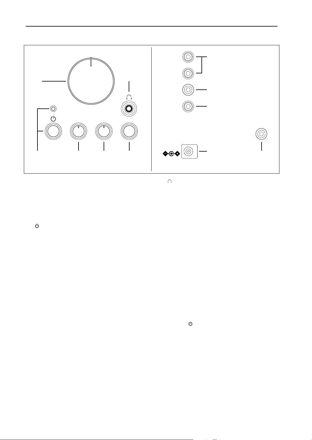
Controls & Connectors
Front Rear
1
VOLUME
BASS TREBLE 3D SURROUND
6
2 3 4 5 A
1
VOLUME control
Allows you to adjust the volume lev el of the entire
speaker system.
Rotating the control clockwise will increase the
volume level, and rotating the control counterclockwise will decrease the level.
2
(standby/on) button/indicator
Press this button to turn on the power to the speaker
system. Its indicator lights up. Press the button
again to set the speaker system to standby mode.
Before pressing this button, make sure that the
VOLUME control setting is lowered. A small electrical current flows through the speaker system
even if the standby/on button is turned off.
3
BASS control
Allows you to adjust the volume level of the low
range.
Rotating the control clockwise will increase the
volume level, and rotating the control counterclockwise will decrease the level.
4
TREBLE control
Allows you to adjust the volume level of the high
range.
Rotating the control clockwise will increase the
volume level, and rotating the control counterclockwise will decrease the level.
5
3D SURROUND switch
INPUT 1
INPUT 2
TO LEFT
SPEAKER
OUTPUT
(ADJ.VOL)
DC 15V
(Right speaker)(Right speaker) (Left speaker)
6
Headphone jack
7
8
9
0
TO RIGHT
SPEAKER
Connect a pair of stereo headphones here to monitor the sound. When you connect the headphones,
the speakers will not output sound.
7
INPUT 1/2
You can input two audio sources to the speaker
system from these input jacks simultaneously. For
example, you can connect the output of a CD
player and a personal computer here. The two
audio sources are mixed together by the speaker
system.
8
TO LEFT SPEAKER (on the right speaker)
Use the RCA plug cable to connect this jack to the
A
TO RIGHT SPEAKER jack on the right speaker
to this connector.
9
OUTPUT (ADJ. VOL)
Use a 3.5mm stereo mini plug cable to connect this
jack to a subwoofer to reinforce the low range.
0
DC connector
Connect the included A C adaptor to this connector.
Press the (standby/on) button on the right
speaker to turn the power on or standby.
A
TO RIGHT SPEAKER (on the left speaker)
Use the RCA plug cable to connect this jack to the
8
TO LEFT SPEAKER jack on the right speaker
to this connector.
Turn this switch on to add 3D surround sound to
the stereo source sound.
Press the switch to turn on the surround effect.
Press it again to turn off the effect. This setting
does not simulate the surround effect through the
headphones.
3
E-
Page 7

4
About YMERSION (3D Enhancement)
YMERSION is Yamaha’s proprietary technology that enhances the spread of a normal stereo source playback sound, creating three-dimensional acoustics using only two speakers.
The 3D SURROUND switch on the right speaker enables you to turn the YMERSION effect on and off.
Troubleshooting
If the speakers fail to operate normally, check the following table. It lists common operation errors and simple measures that you can take to correct problems. If a problem cannot be corrected, or the symptom is not listed, disconnect the AC adaptor and contact your authorized YAMAHA dealer or service center for help.
FAULT CAUSE CURE
No sound comes
from the speakers.
Sound is distorted. The level of the input signal is too high. Turn down the volume on the connected device.
The 3D sound can-
not be heard.
Noise. Connections are faulty or incomplete. Make the connections again, firmly, or use a different
Even if the (standby/on) button is turned off, a small amount of sound may be heard from the headphones if the
VOLUME control is set to max. This is normal.
If the VOLUME control is set to max. while the headphones are connected, you may hear a small amount of sound
from the speakers. This is normal.
The AC adaptor is not properly plugged into
the AC receptacle.
The (standby/on) button on the right
speaker is turned off or the AC adaptor is not
plugged into the AC receptacle and the DC
connector completely.
The volume is set to minimum. Turn the speaker VOLUME control to the right to
The level of the input signal is too low. Turn up the volume on the connected device.
Connections are faulty or incomplete. Make the connections again, firmly, or use a different
The sound source is monaural. Playback the stereo source.
Insert the AC adaptor firmly into the AC receptacle.
Plug the AC adaptor completely into the AC receptacle
and DC connector, then turn on the (standby/on)
button on the right speaker.
increase the volume.
cable.
cable.
English
Non skid pad
To prevent the speakers from sliding around, attach the supplied pads to the four points on
the bottom of speaker, as shown. Place the speaker on a stable, flat surface.
E-
Page 8

Specifications
Type Advanced Y amaha Active Servo Technology
Output power 12 W + 12 W (1 kHz, 4Ω at T.H.D. = 10%)
Input sensitivity 200 mV (1 kHz, 4Ω at 12 W)
Input impedance 20 kΩ
Frequency response 70 Hz to 20 kHz
Input Section Right speaker ........3.5 mm stereo mini jack for audio-signal × 2
AC adaptor jack
Left speaker...........RCA pin jack connected to right speaker
Output Section RCA pin jack connected to left speaker
3.5 mm stereo mini jack for audio-signal
Output level 0.7 V/330Ω (200 mV)
Driver 8 cm (3") full range cone, magnetic shielding
H.P. Output level 0.45 V/30Ω (200 mV)
Power supply U.S.A. and Canada models......AC 120 V, 60 Hz
(AC adaptor) Australia model..... ..................AC 240 V, 50 Hz
U.K. and Europe models.......... AC 230 V, 50 Hz
Dimensions (W × H × D) Right speaker........95 (3.7") × 248 (9.8") × 203 (8") mm
Left speaker...........95 (3.7") × 248 (9.8") × 199 (7.8") mm
Weight Right speaker ........1.1 kg (2.43 lbs)
Left speaker...........0.8 kg (1.76 lbs)
Accessories AC adaptor × 1
3.5 mm stereo mini plug cable × 1
RCA pin plug cable × 1
8 pcs of non skid pads × 1 set
* Specifications subject to change without notice.
Please contact an authorized Yamaha dealer for more information on this product or connections to your computer.
5
E-
Page 9

Printed in China
IP
V532450
 Loading...