

Yamaha YSP-CU3300, YSP-CU4300, YSP-3300, NS-WSW160 User Manual
@
YSP-4300
[ YSP-CU4300+ NS-WSWI60]
YSP-3300
[YSP-CU3300 + NS-WSW160]
Digital Sound Projector TM
Owner,s Manual
English
for NorthAmerica
J
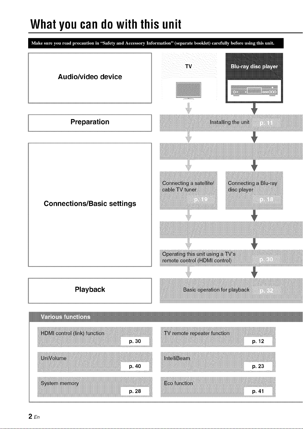
Whatyoucandowiththisunit
Audio/video device
Preparation
TV
Connections/Basic settings
Playback
2En
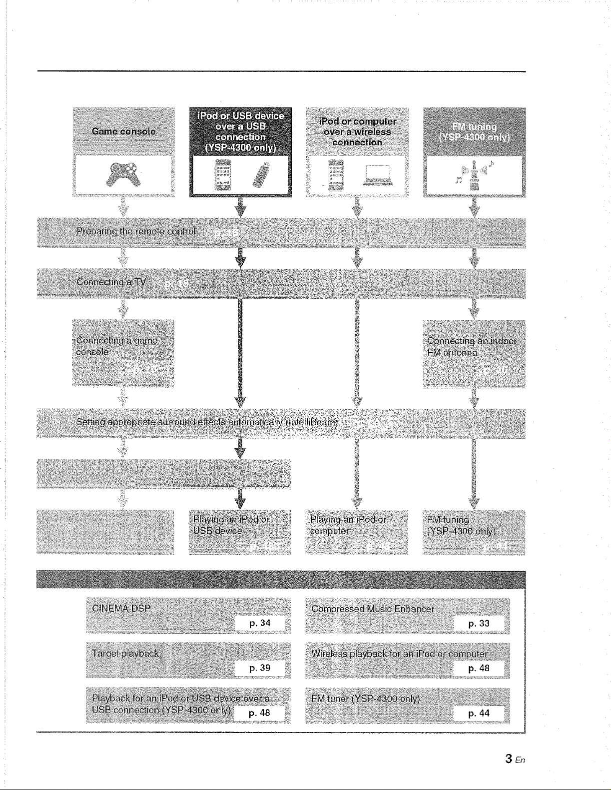
p. 39
3En
Contents
PREPARATION
Controls and functions ............................................... 5
Center unit front panel (front, top) ........................................... 5
Center unit rear panel (back) .................................................. 6
Subwoofer rear panel (back) ................................................... 7
Front panel display .................................................................. 8
Remote control ........................................................................ 9
Installation ................................................................. 11
Recommended installation .................................................... 11
Conditions that make it difficult for sound beams
to achieve surround sound .................................................... 11
Enjoying surround effects regardless of conditions
(My Surround) ....................................................................... 12
If the TV remote control does not work properly after the center
unit is installed (TV Remote Repeater function) ................... 12
If the center unit cannot be installed on a TV stand
(increasing the height of the center unit) ............................... 12
Positioning the subwoofer on its side .................................... 13
Installing this unit .................................................................. 14
Preparing remote control .............................................. 16
Installing the batteries ........................................................... 16
Operation range .................................................................... 16
Connections .............................................................. 17
Connecting a TV and a Blu-ray disc player ................... 18
Connecting a game console or
satellite/cable TV tuner ................................................. 19
Connecting the FM antenna (YSP-4300 only) .............. 20
Connecting the wireless subwoofer .............................. 20
Initial settings ............................................................ 21
Establishing a wireless connection ............................... 21
Group IDs .............................................................................. 21
Displaying the menu screen on the TV ......................... 21
Selecting the language for menu display ...................... 22
Auto setup for appropriate surround effects
(IntelliBeam) .................................................................. 23
Installing the IntelliBeam microphone ................................... 23
Using AUTO SETUP (IntelliBeam) ........................................ 24
Saving this unit's settings to system memory ....................... 28
Operating the unit by TV's remote control
(HDMI control) ............................................................... 30
PLAYBACK
Playback features ...................................................... 32
Basic operation for playback ......................................... 32
Enjoying sound based on your preference ................... 33
Switching between surround playback, stereo playback, and
target playback modes .......................................................... 33
Playing back digitally compressed formats (MP3, WMA, etc.)
with enriched sound (Compressed Music Enhancer) ........... 33
Adjust volume for each channel ............................................ 33
Enjoying realistic surround sounds (CINEMA DSP) ............. 34
Changing the audio output method for surround playback ... 36
Setting the surround decoder ................................................ 38
Delivering sound to a specified location
(Target playback mode) ........................................................ 39
Using useful features .................................................... 40
Automatic volume level adjustment (UniVolume) ................. 40
Saving energy with the Eco function ..................................... 41
Switching information displayed in the front panel display.... 41
Settings each input source (Option menu) ............................ 42
FM tuning (YSP-4300 only) ........................................... 44
Tuning into the desired FM station (Frequency tuning) ........ 44
Receiving weak signal ........................................................... 45
Registering FM stations and tuning in (Preset tuning) ........... 45
Playing music stored on an iPod or computer
over a wireless connection ........................................... 48
Playing music stored on an iPod or USB device
over a USB connection (YSP-4300 only) ..................... 48
Connecting an iPod ............................................................... 48
Operating an iPod via the TV screen ..................................... 49
Using the iPod to control operation ....................................... 52
Charging the iPod .................................................................. 53
Connecting a USB device ...................................................... 54
Operating a USB device via the TV screen ........................... 55
SETTINGS
Setup menu ............................................................... 58
Setting the setup menu ................................................ 58
Setup menu list ............................................................ 59
BEAM settings .............................................................. 60
HORIZONTAL ANGLE .......................................................... 60
BEAM TRAVEL LENGTH ...................................................... 60
FOCAL LENGTH ................................................................... 60
IMAGE LOCATION ................................................................ 61
CHANNEL OUT ..................................................................... 61
SOUND settings ........................................................... 62
SPEAKER LEVEL ................................................................. 62
Adaptive DRC ........................................................................ 62
DYNAMIC RANGE ................................................................ 63
Dolby PLIIx PARAMETER ..................................................... 63
HDMI setup .................................................................. 63
HDMI CONTROL ................................................................... 63
HDMI AUDIO OUT ................................................................. 63
TV INPUT .............................................................................. 63
yAired settings .............................................................. 64
iPod INTERLOCK .................................................................. 64
GROUP ID ............................................................................. 64
DISPLAY settings ......................................................... 65
DIMMER ................................................................................ 65
OSD LANGUAGE .................................................................. 65
DISTANCE UNIT ................................................................... 65
INFORMATION settings ............................................... 65
AUDIO ................................................................................... 65
VIDEO ................................................................................... 65
SYSTEM ................................................................................ 65
Advanced setup ........................................................ 66
TROUBLESHOOTING
Troubleshooting ....................................................... 68
General .................................................................................. 68
FM tuner (YSP-4300 only) ..................................................... 70
USB device (YSP-4300 only) ................................................ 70
Remote control ...................................................................... 70
Messages .................................................................. 71
iPod (when connected via USB jack)/
USB device (YSP-4300 only) ................................................ 71
APPENDIX
Glossary .................................................................... 72
Specifications ........................................................... 74
Available signal information ......................................... 76
Index .......................................................................... 77
4En
n_l'n :01_ fO tli
ooil
nan ),
.1Cat tlD y
ont_ _mp_ n
nan _the _P m_t [l ons _or _
Controlsandfunctions
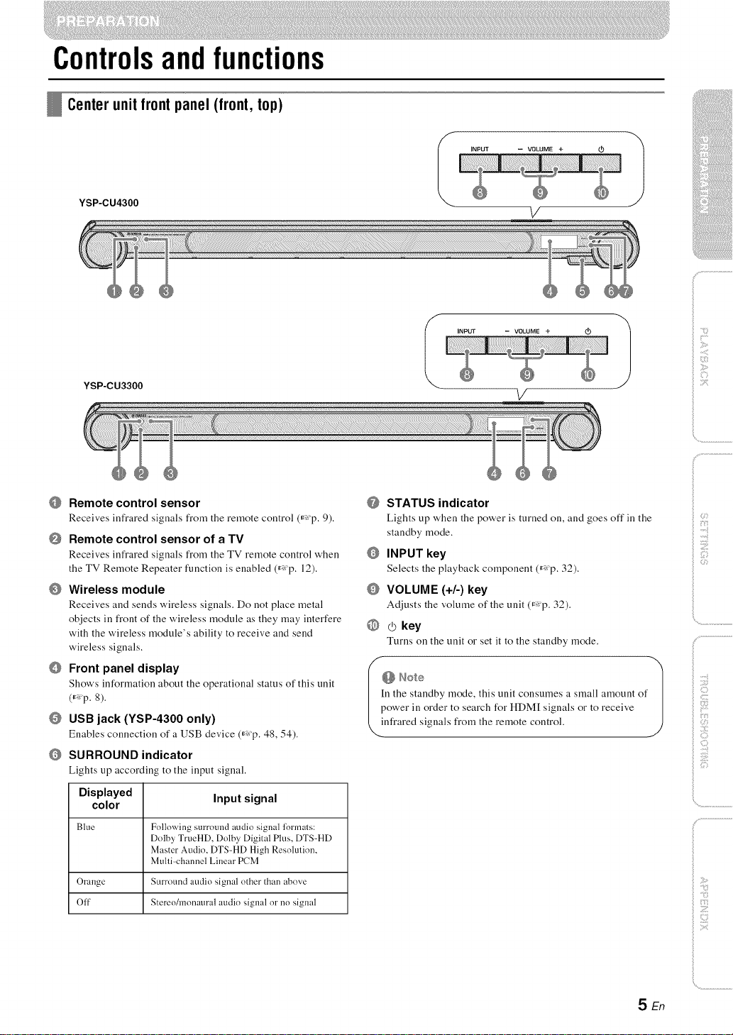
Centerunitfrontpanel(front,top)
YSP-CU4300
I iNPUT -- VOLUME +
V
YSP-CU3300
Remote control sensor
Receives infrared signals from the remote control (_'p. 9).
Remote control sensor of a TV
Receives infrared signals fi'c)m the TV remote control when
the TV Remote Repeater function is enabled (_ p. 12).
O Wireless module
Receives and sends w'ireless signals. Do not place metal
objects in front of the wireless module as they may interfere
with the w'ireless module's ability to receive and send
wireless signals.
Front panel display
Show's information about the operational status of this unit
(_ p. 8).
USB jack (YSP-4300 only)
Enables connection of a USB device (_ p. 48, 54).
SURROUND indicator
Lights up according to the input signal.
I NPUT - VOLUME+_ 1
V
@ STATUS indicator
Lights up when the power is turned on, and goes off in the
standby mode.
INPUT key
Selects the playback component (_ p. 32).
VOLUME (+/-) key
Adjusts the volume of the unit (_ p. 32).
@ _ key
Turns on the unit or set it to the standby mode.
n the standby mode, this unit consumes a small amount of
ower in order to search for HDM[ signals or to receive
infi:ared signals fi:om the remote control.
ilii_i_i_iiii_!i!i!iii!!i!_
', ,,iiiiii_'_!_i_iII!............
)
Displayed Input signal
color
Blue Following surrotmd audio signal lormats:
Orange Surround audio signal other than above
Off Stereo/monam'al audio signal or no signal
Dolby TrueHD, Dolby Digital Plus, DTS-HD
Master Audio, DTS-HD High Resolution,
Multi-channel Linear PCM
SEn
Controls and functions
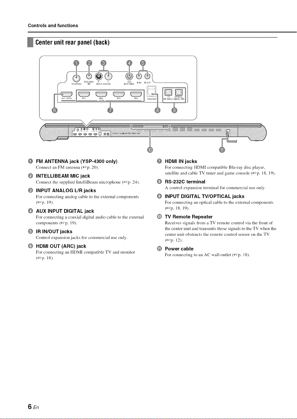
Centerunit rear panel (back)
FM ANTENNA jack (YSP-4300 only)
Connect all FM antenna (_ p. 20).
INTELLIBEAM MIC jack
Connect the supplied [ntelliBeam microphone (_p. 24).
O INPUT ANALOG L/R jacks
For connecting analog cable to the external components
(_*_p. 19).
AUX INPUT DIGITAL jack
For connecting a coaxial digital audio cable to the external
components (_*_p. 19).
IR IN/OUT jacks
Control expansion jacks for commercial use only.
HDMI OUT (ARC)jack
For connecting an HDM[ compatible TV and monitor
(_*:p. 18).
@
HDMI IN jacks
For connecting HDM[ compatible Blu-ray disc player,
satellite and cable TV tuner and game console (_p. 18, 19).
Q
RS-232C terminal
A control expansion terminal for commercial use only.
O
INPUT DIGITAL TV/OPTICAL jacks
For connecting an optical cable to the external components
(_Xp. 18, 19).
@
TV Remote Repeater
Receives signals from a TV remote control via the front of
the center unit and transmits those signals to the TV when the
center unit obstructs the remote control sensor on the TV
(_*:p. 12).
Power cable
For connecting to an AC wall outlet (_p. 18).
SEn
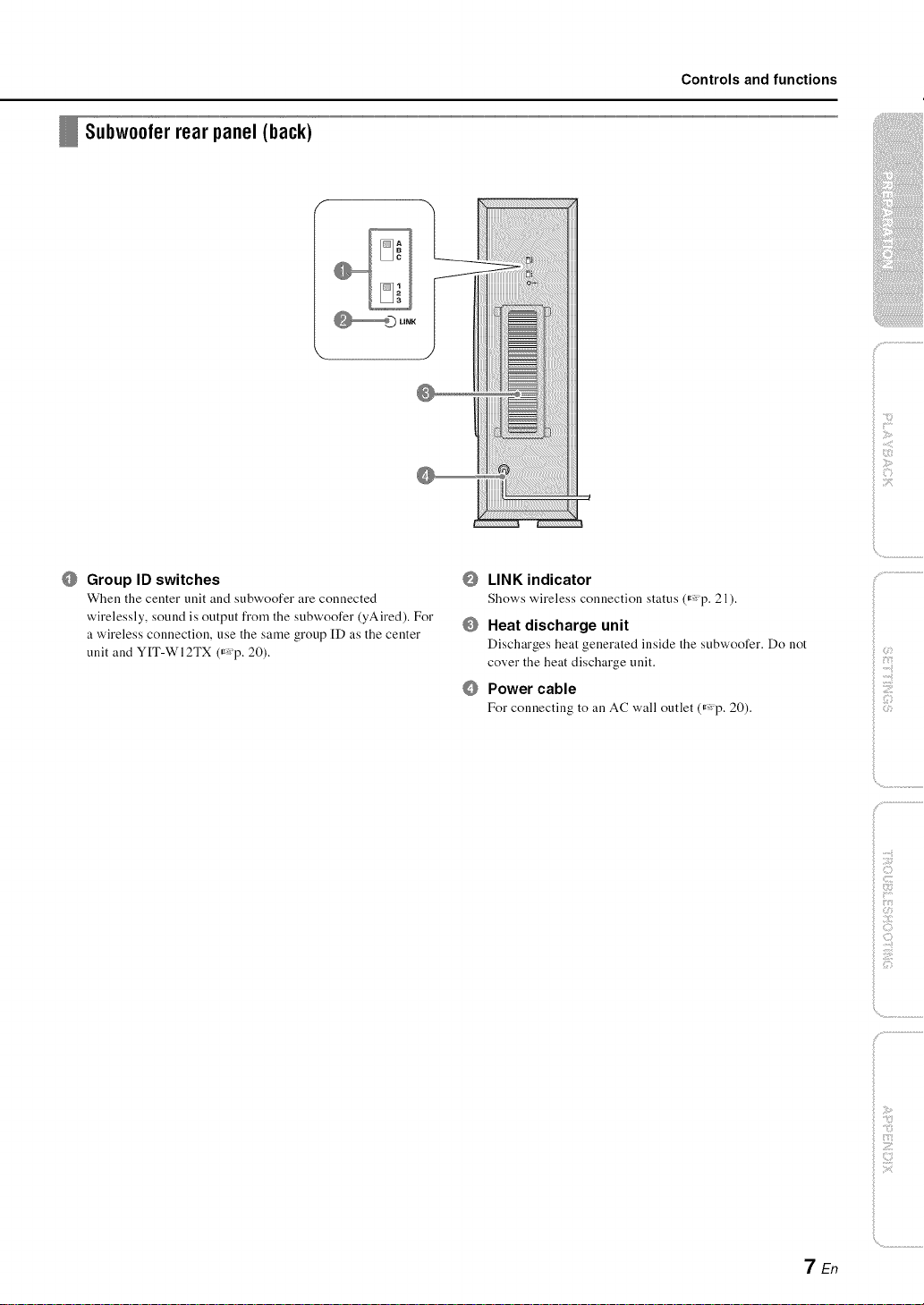
Subw00ler rearpanel (back)
Controls and functions
ilii_i_i_iiii_!i!i!iii!!i!_
', ,,iiiiii_'_!_i_iII!............
Group ID switches
When the center unit and subwoofer are connected
wirelessly, sound is output from the subwoofer (yAired). For
a wireless connection, use the same group ID as the center
unit and YIT-WI2TX (r'p. 20).
LINK indicator
Shows wireless connection status (_p. 21).
Heat discharge unit
Discharges heat generated inside the subwoofer. Do not
cover the heat discharge unit.
O
Power cable
For connecting to an AC wall outlet (_Xp. 20).
)
_ :7
7En
Controls and functions
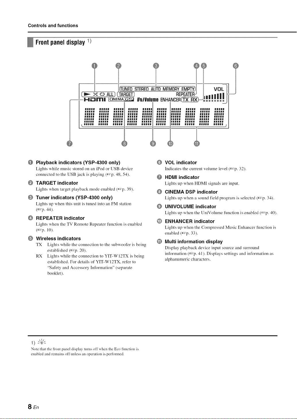
Frontpanel display_)
mmmJl
gHgHB BJg_B UB|_ gff_ng
li_ml
mmmml
mmm_m
_mWU _Jm_m M_WMm mmm_u
mmlJJ
|JJJ_ lJ_ml ll|ll miami
_l|mm
_umll ilgll iU|_m llmll
gm|ml
Playback indicators (YSP-4300 only)
Lights while music stored on an iPod or USB device
connected to the USB jack is playing (_ p. 48, 54).
TARGET indicator
Lights when target playback mode enabled (_,:p. 39).
Tuner indicators (YSP-4300 only)
Lights up when this unit is tuned into an FM station
(_:'p. 44).
REPEATER indicator
Lights when the TV Remote Repeater function is enabled
(_ p. 10).
Wireless indicators
TX Lights while the connection to the subwoofer is being
established (_,:p. 20).
RX Lights while the connection to YIT-WI2TX is being
established. For details of YIT-WI2TX, refer to
"Safety and Accessory [nformation" (separate
booklet).
VOL indicator
Indicates the current volume level (_ p. 32).
@ HDMI indicator
Lights tip when HDM[ signals are input.
CINEMA DSP indicator
Lights tip when a sound field program is selected (_ p. 34).
UNIVOLUME indicator
Lights tip when the UniVolume function is enabled (_: p. 40).
@ ENHANCER indicator
Lights tip when the Compressed Music Enhancer function is
enabled (_: p. 33).
O Multi information display
Display playback device input source and surround
information (_,:p. 41). Displays settings and information as
alphanumeric characters.
Note that the front panel display turns off when the Eco fnnctinn is
enabled and remains off unless an operation is perfnrmed.
SEn
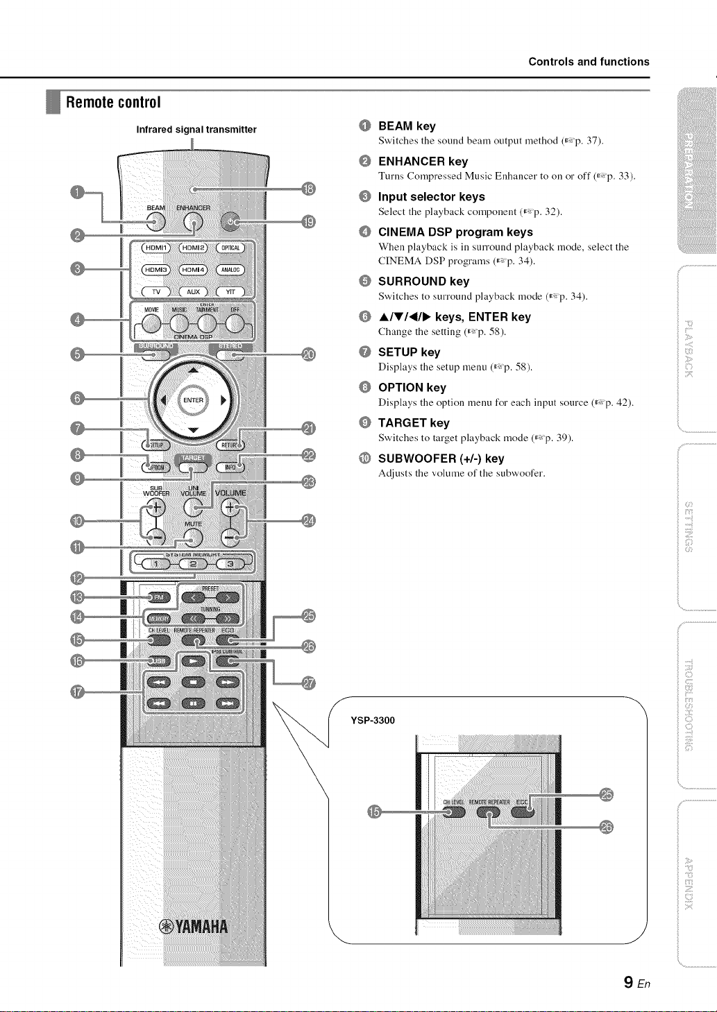
Remotecontrol
Infrared signal transmitter
Controls and functions
@
BEAM key
Switches tile sound beam output lllethod (ir_ p. 37).
@
ENHANCER key
Turns Compressed Music Enhancer to on or off (_p. 33).
@
Input selector keys
Select the playback component (_ p. 32).
@
CINEMA DSP program keys
When playback is ill surround playback mode, select the
CINEMA DSP programs (_,: p. 34).
@
SURROUND key
Switches to surround playback mode (_,:p. 34).
@
A/V/_/I_ keys, ENTER key
Change the setting (_ p. 58).
@
SETUP key
Displays the setup menu (_p. 58).
@
OPTION key
Displays the option menu for each input source (_ p. 42).
@
TARGET key
Switches to target playback mode (_,: p. 39).
@
SUBWOOFER (+/-) key
Adjusts the volume of the subwoofer.
ilii_i_i_iiii_!i!i!iii!!:!_
', ,,iii;ii_'_!_i_iII!............
)
|
YSP-3300
_:_i_iii!i_i!i{{!i
!!iiii';
\
/
..........
YEn
Controls and functions
@ MUTE key
Mute the sound (_: p. 32).
@ SYSTEM MEMORY keys
Saves [ntelliBeam measurements, speaker volume, and other
settings (_: p. 28).
@ FM key (YSP-4300 only)
Switches this tmit's input source to FM radio.
@ Tuner operation keys (YSP-4300 only)
Press to select or register all FM station (_ p. 44).
@ CH LEVEL key
Adjusts the volume balance during playback (_ p. 33).
@ USB key (YSP-4300 only)
Switches this unit's input source to USB (_ p. 48).
@ Playback operation keys (YSP-4300 only)
Perform playback operations for music stored on an iPod or
USB device (_: p. 48).
@ Transmission indicator
Lights with operation using this unit's remote control.
@ (.5key
Turns on the unit or set it to the standby mode (_ p. 32).
@ STEREO key
Switches to stereo playback mode (_ p. 33).
@ RETURN key
Returns to the previous menu screen.
@ INFO key
Switches the information display on the front panel as
follows.
• [nput: [nput name
• Beam: Beam mode setting (stereo, beam stereo, target, or
surround playback mode)
• Decoder: Sound signal decoder currently selected
• Cinema DSP: Sound field program of CINEMA DSP
(only in surround playback mode)
[nformatiou displayed varies according to the selected input
source (_: p. 41, 51, 53, 56).
@
UNIVOLUME key
Turns the UuiVolume function on or off (_ p. 40).
@
VOLUME (+/-) key
Adjusts the volume of the unit (_ p. 32).
@
ECO key
Turns the Eco function on or off (_ p. 41).
@
REMOTE REPEATER key
Turns the TV Remote Repeater function on or off (_ p. 12).
@
iPod CONTROL key (YSP-4300 only)
Press to display the iPod browse/playback screen on the TV
(_ p. 51).
lO En
Demo mode
This uuit outputs souud beam dowu-mixed to 1 chauuel
moving horizontally to right and left. By this function, you
can feel how' sound beam is output from this unit.
To activate Demo mode:
"1 Press the TARGET key on the remote control.
2 Press the CINEMA DSP OFF key.
"AUTO DEMO" is shown in the front panel display when
demo mode starts.
To exit demo mode, press the CINEMA DSP OFF key
again. The display returns to target playback mode display.
J
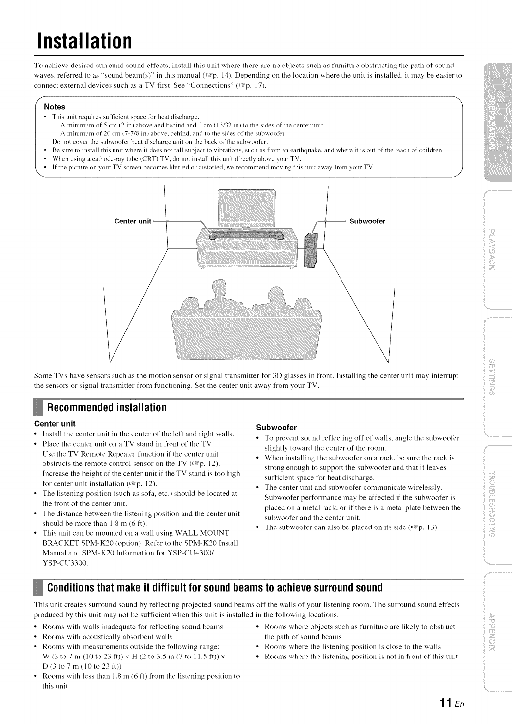
Installation
To achieve desired surround sound effects, install this unit where there are no objects such as furniture obstructing the path of sound
waves, referred to as "sound beam(s)" ill this manual (_,: p, 14), Depending on the location where the unit is installed, it may be easier to
connect external devices such as a TV first, See "Connections" (_,: p, 17),
f
Notes
• This unit requires sufficient sp_ce li)r heat discharge.
A mininmm of 5 cm (2 in) above and behind and 1 cm (13/32 in) to the sides of the center unit
A minimum of 21) cm (7-7/8 in) above, behind, and to the sides of the subwoofer
Do not cover the subwoofer heat discharge unit on the back of the subwooli2r.
• Be sure to install this unit where it does not fall subject to vibrations, such as from an earthquake, and where it is out of the reach of children.
• When using acathode-ray tube (CRT) TV, do not install this unit directly above your TV.
• If the picture on your TV screen becomes blurred or distorted, we recommend moving this unit away li'om your TV.
Center unit -- Subwoofer
ilii_i_i_iiii_!i!i!iii!!:!_
', ,,;ii;ii_'_!_i_iII!............
Some TVs have sensors such as the motion seusor or signal transmitter for 3D glasses in frout. Iustalliug the ceuter uuit may iuterrupt
the seusors or sigual trausmitter from fuuctiouiug, Set the ceuter uuit away from your TV.
Recommendedinstallation
Center unit
• [nstall the center unit in the center of the left and right walls,
• Place the center unit on a TV stand in front of the TV,
Use the TV Remote Repeater function if the center unit
obstructs the remote control sensor on the TV (_,: p, 12),
[ncrease the height of the center unit if the TV stand is too high
for center unit installation (_,:p, 12),
• The listening position (such as sofa, etc,) should be located at
the front of the center unit,
• The distance between the listening position and the center unit
should be more than 1,8 m (6 ft),
• This unit can be mounted on a wall using WALL MOUNT
BRACKET SPM-K20 (option), Refer to the SPM-K20 [nstall
Manual and SPM-K20 [nformation for YSP-CU4300/
YSP-CU3300.
Subwoofer
• To prevent sound reflecting off of walls, angle the subwoofer
slightly toward the center of the room.
• When installing the subwoofer on a rack, be sure the rack is
strong enough to support the subwoofer and that it leaves
sufficient space for heat discharge,
• The center unit and subwoofer communicate wirelessly.
Subwoofer performance may be affected if the subwoofer is
placed on a metal rack, or if there is a metal plate between the
subwoofer and the center unit,
• The subwoofer can also be placed on its side (_,: p, 13),
Conditionsthat makeit difficultforsoundbeamsto achievesurroundsound
This unit creates surround sound by reflecting projected sound beams off the walls of your listening room. The surround sound effects
produced by this unit may not be sufficient when this unit is installed in the following locations,
• Rooms with walls inadequate for reflecting sound beams
• Rooms with acoustically absorbent walls
• Rooms with measurements outside the following range:
W (3 to 7 m (10 to 23 ft)) x H (2 to 3,5 m (7 to 11,5 ft)) x
D (3 to7 m (10 to 23 ft))
• Rooms with less than 1,8 m (6 ft) from the listening position to
this unit
• Rooms where objects such as furniture are likely to obstruct
the path of sound beams
• Rooms where the listening position is close to the walls
• Rooms where the listening position is not in front of this unit
11 En
)
i©
iiili_i_ii:i_!!!i!ii:i!
i
Installation
Enj0yingsurround effects regardless of conditions (My Surround)
The My Surround function creates rich surround sound effects ill rooms with less than optimal surround sound conditions (,_p. 11 ). See
"Changing the audio output method for surround playback" (,_ "p. 36, 37) for more information.
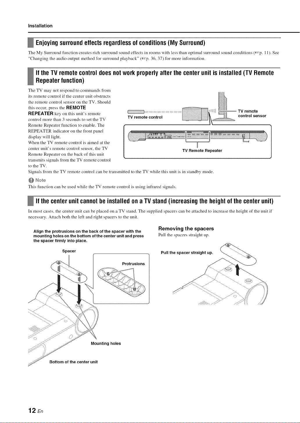
Ifthe TV remotecontroldoesnotworkproperly afterthecenterunitis installed(TV Remote
Repeaterfunction)
The TV may not respond to commands from
its reruote control if the center unit obstructs
the remote control sensor on the TV. Should
this occur, press the RI_MOTI _
RI_pI_ATI_R key on this unit's remote
control more than 3 seconds to set the TV
Remote Repeater function to enable. The
REPEATER indicator on the front panel
display will light.
When the TV remote control is aimed at the
center unit's remote control sensor, the TV
Remote Repeater on the back of this unit
transmits signals from the TV remote control
to the TV.
Signals from the TV remote control can be transmitted to the TV while this unit is in standby mode.
@ Note
This function can be used while the TV remote control is using infrared signals.
TV remote control
TV Remote Repeater
TV remote
control sensor
Ifthe centerunitcannotbeinstalled ona TVstand(increasingthe heightof the centerunit)
In most cases, the center unit can be placed on a TV stand. The supplied spacers can be attached to increase the height of the unit if
necessary. Attach both the left and right spacers to the unit.
Align the protrusions on the back of the spacer with the
mounting holes on the bottom of the center unit and press
the spacer firmly into place.
Spacer
Protrusions
Mounting holes
Bottom of the center unit
Removing the spacers
Pull the spacers straight up.
Pull the spacer straight up.
12 En
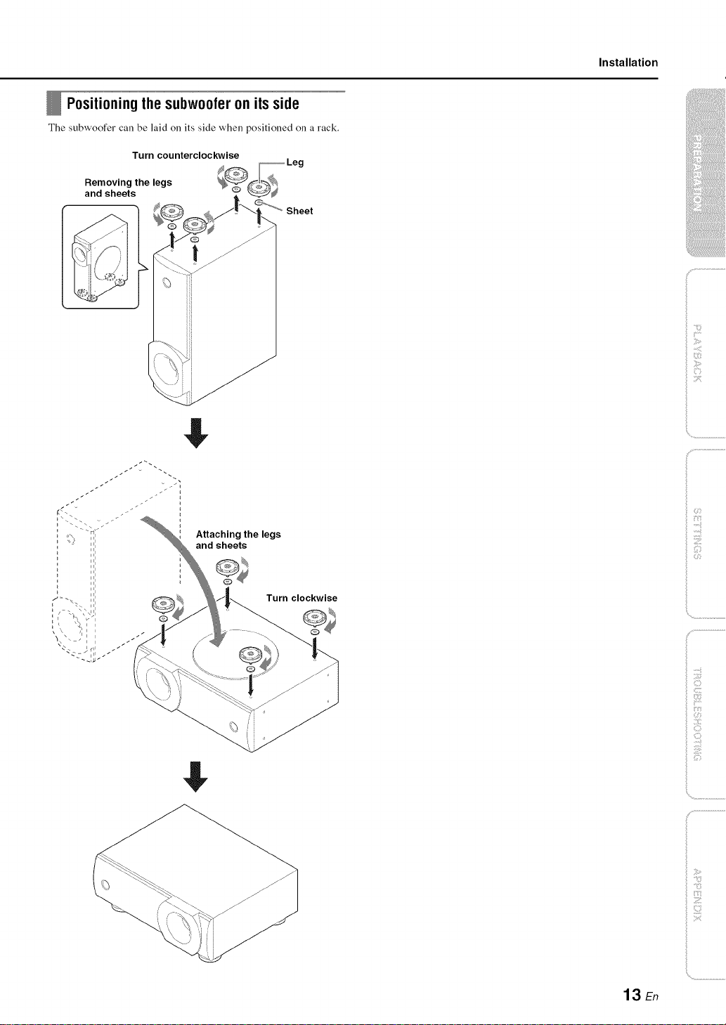
Positioning the subwoofer on its side
The subwoofer call be laid on its side when _ositioned on a rack.
Turn counterclockwise
Removing the legs
and sheets
Sheet
$
Installation
ilii_i_i_iiii_!i!i!iii!!i!_
', ,,iiiiii_'_!_i_iII!............
Attaching the legs
and sheets
$
Turn clockwise
i!il Z;i:i_
_!_iZI_II'I!III
!i!i _iiiii_iiii__
13 En
Installation
Installing this unit
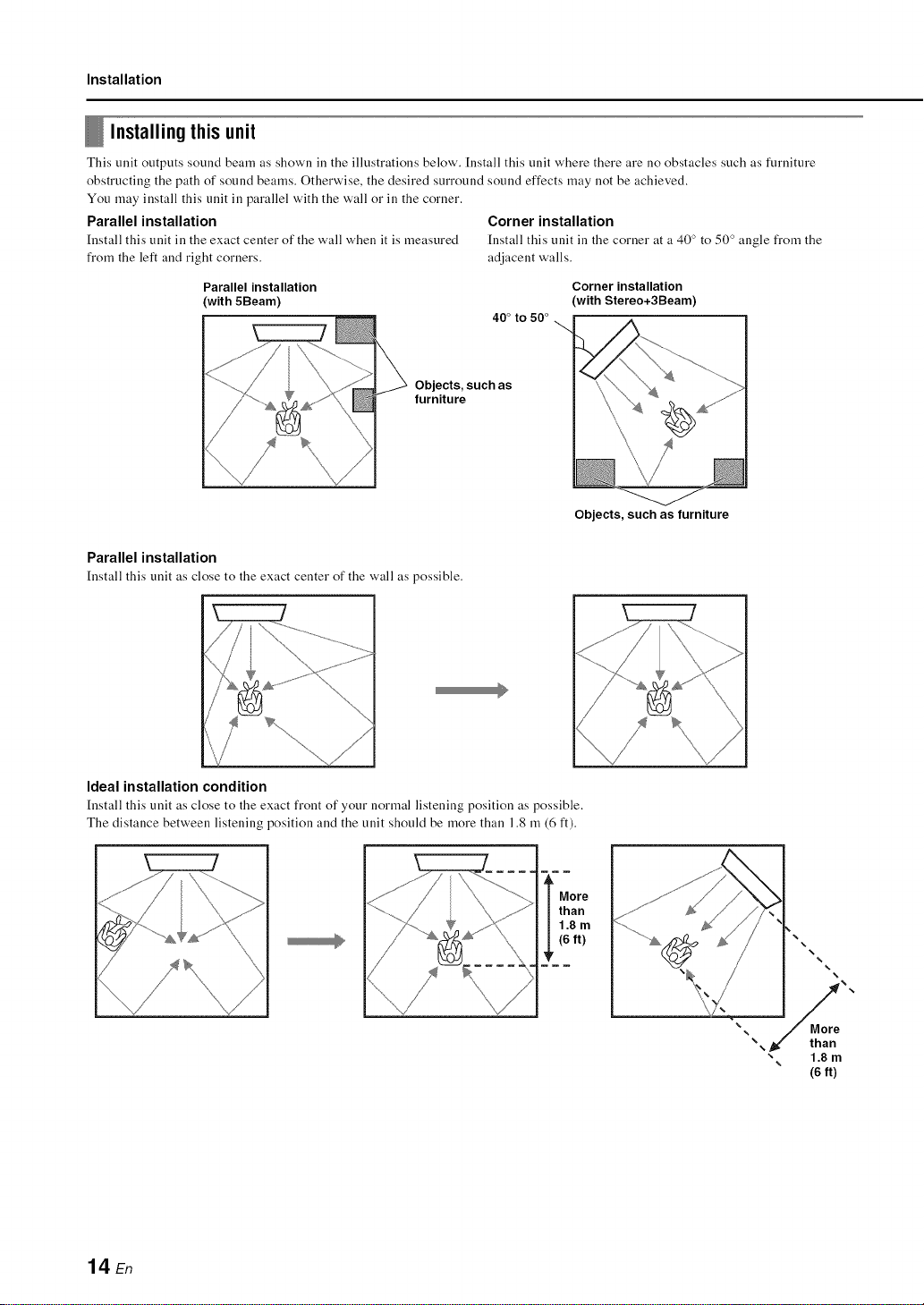
This unit outputs sound beam as shown ill the illustrations below'. Install this unit where there are no obstacles such as furniture
obstructing the path of sound beams. Otherwise, the desired surround sound effects may not be achieved.
You may install this unit ill parallel with the wall or ill the corner.
Parallel installation Corner installation
[nstall this unit in the exact center of the wall when it is measured [nstall this unit in the corner at a 40 ° to 50 ° angle from the
from the left and right corners, adjacent walls.
Parallel installation
(with 5Beam)
Objects, such as
furniture
Parallel installation
[nstall this unit as close to the exact center of the wall as possible.
40° to 50 °
Corner installation
(with Stereo+3Beam)
Objects, such as furniture
Ideal installation condition
[nstall this unit as close to the exact front of your normal listening position as possible.
The distance between listening position and the unit should be more than 1.8 m (6 ft).
¥
14 En
More
than
1.8 m
(6ft)
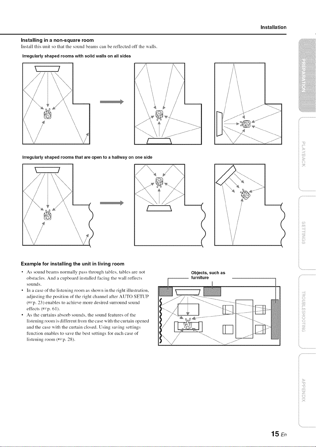
Installing in a non-square room
[nstall this unit so that the sound beams call be reflected off the walls.
Irregularly shaped rooms with solid walls on all sides
Installation
Irregularly shaped rooms that are open to a hallway on one side
Example for installing the unit in living room
• As sound beams normally pass through tables, tables are not
obstacles. And a cupboard installed facing the wall reflects
sounds.
• In a case of the listening room as shown in the right illustration,
adjusting the position of the right channel after AUTO SETUP
(_: p. 23) enables to achieve more desired surround sound
effects (_: p. 61).
• As the curtains absorb sounds, the sound features of the
listening room is different from the case with the curtain opened
and the case with the curtain closed. Using saving settings
function enables to save the best settings for each case of
listening room (_: p. 28).
-- furniture
Objects, such as
ilii_i_i_iiii_!i!i!iii!!i!_
', ,,iiiiii_'_!_i_iII!............
c:
15 En
Installation
Before installing batteries o1"using the remote control, be sure to read battery and remote control precautions ill "Safety and Accessory
Information" (separate booklet).
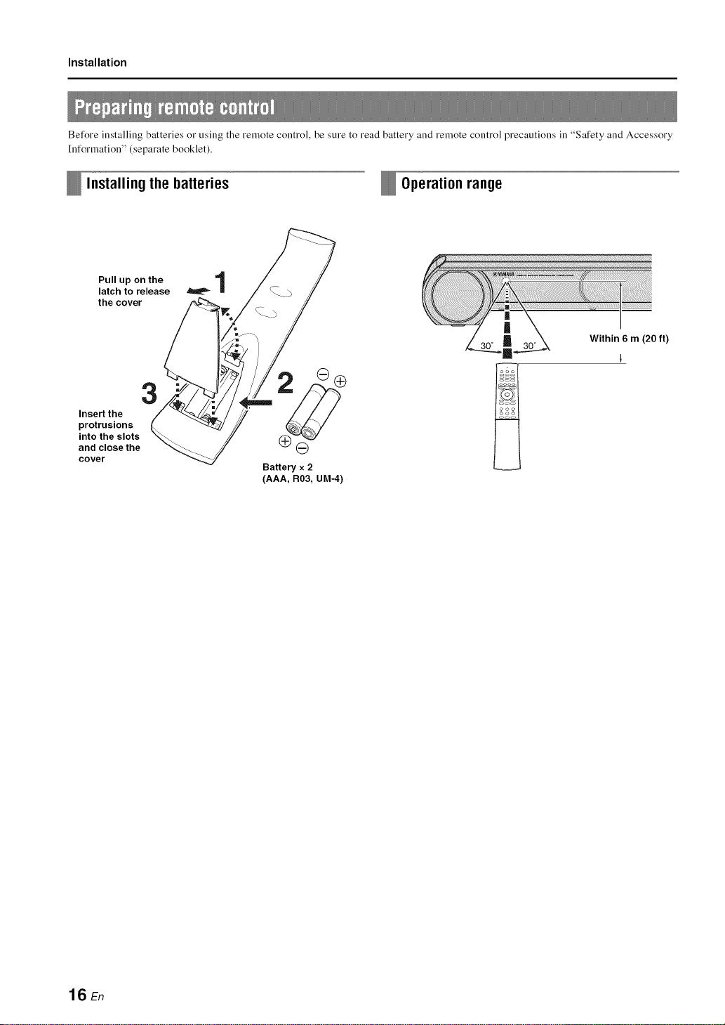
Installingthe batteries Operationrange
Pull up on the 1
latch to release
the cover
3
Insert the
protrusions
into the slots
and close the
cover
ll
,_i¸¸ _,ii,ii,i_,_,_J_,__"_'_'_ii_iiiiiiiii!!!!!i!!i!!!i!!!i!!iii!iiiiiiiiiiiiiiiiiiiiiiiiiiiiiiiiiiiiiiiiiii_ii!iiiiliiiiiiiiiii_iiiiiii_i!i!i!iiiiiiiii!iiiiiiiiiiiiiiiiii!_,,i
ft)
G
Battery x 2
(AAA, R03, UM-4)
16 En
Connections
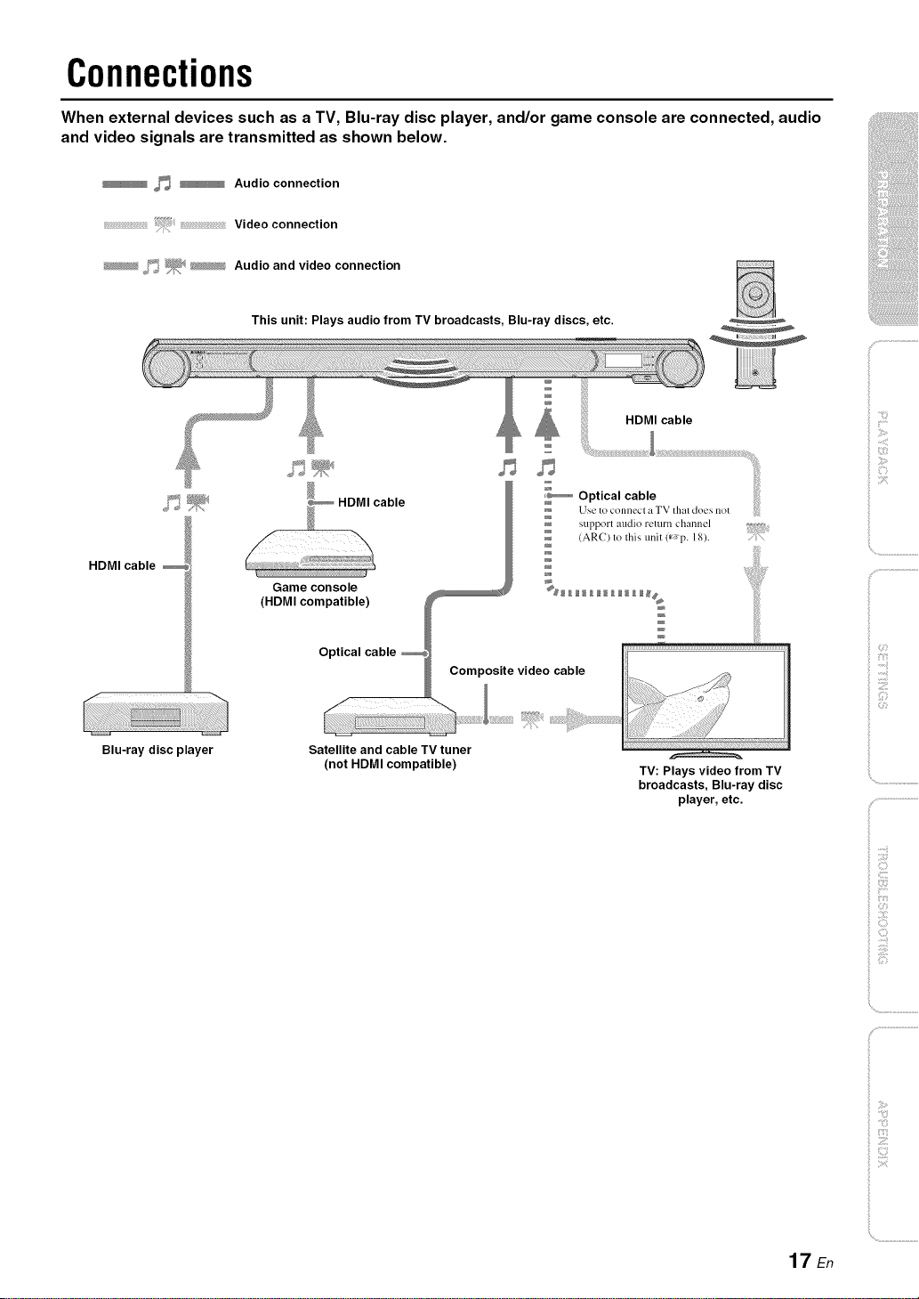
When external devices such as a TV, Blu-ray disc player, and/or game console are connected, audio
and video signals are transmitted as shown below.
_ _ Audio connection
Video connection
_ f_ _; _ Audio and video connection
This unit: Plays audio from TV broadcasts, Blu-ray discs, etc.
HDMI cable
i P
Use to connecl a TV that does not
support audio return channel
(AR() to this unit (*_'p. 18).
HDMI cable
Game console __ %_ _ ___ _____
(HDMI compatible) W __#
/
Optical cable _
_ Comp_ite video cable
i
iliiii_iiii_!i!i!iii!!:!_
iC,
', ,,iiiiii_'_!_i_iII!............
f
Blu-ray disc player
Satellite and cable TV tuner
(not HDMI compatible) TV: Plays video from TV
broadcasts, Blu-ray disc
player, etc.
_ ;!i;¸
17 En
Connections
_] Do not connect the power cable until all connections are completed,
Do not use excessive force when inserting the cable plug, Doing so may damage the cable plug and/or jack.
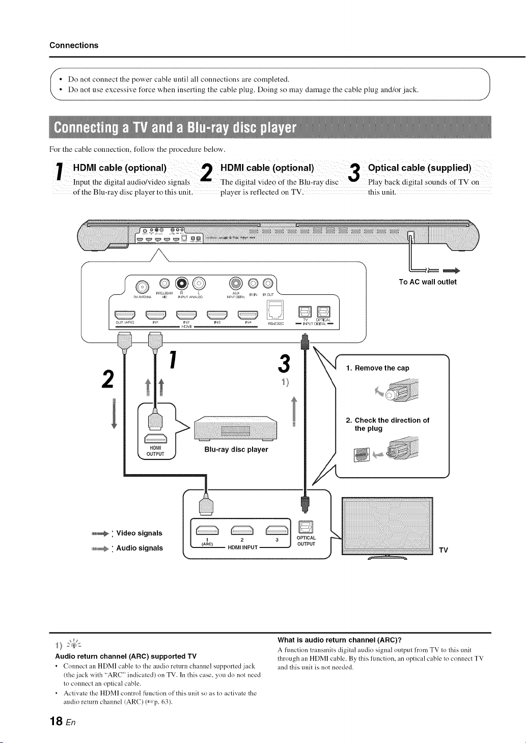
For the cable connection, follow the procedure below,
HDMI Cable (optional)cable(opti0nal)3 optical Cable(supplied)
inpu[ ;he digital audi;/video ;ignMs The digital videO ofihe BiuT;ay disc back digital soun]ts of TV ;n
Of the Blu-ray disc player to this unit. player is reflected on TV: this unit.
To AC wall outlet
INr b._AM AUX
FV '_N_T?_NA _,_lC INPUT ANA O_ I_LT ;;ISI[_t V_IN InO
TV OmlCAL
OUT (ARO]
IN_ IN2 INS INa RZ-2a2C
HOMI
DD]
INPtr 01_1_E
J
1 3
2
i
Blu-ray disc player
_ " Video signals
_ " Audio signals
Audio return channel (ARC) supported TV
• ColmectanHDMlcabletotheaudioremrnchannelsupl_ortedjack
(the jack with "ARC" indicated) on TV. In this case, you do not need
to connect an optical cable.
• Activate the HDMI control function of this trait so as to activate the
audio return channel (ARC) (_,p. 63).
TV
What is audio return channel (ARC)?
A [iulction transmits digital audio signal output l]'orn TV to this tlnit
through an HDMI cable. By this flmction, an optical cable to connect TV
and this trait is not needed.
18 En
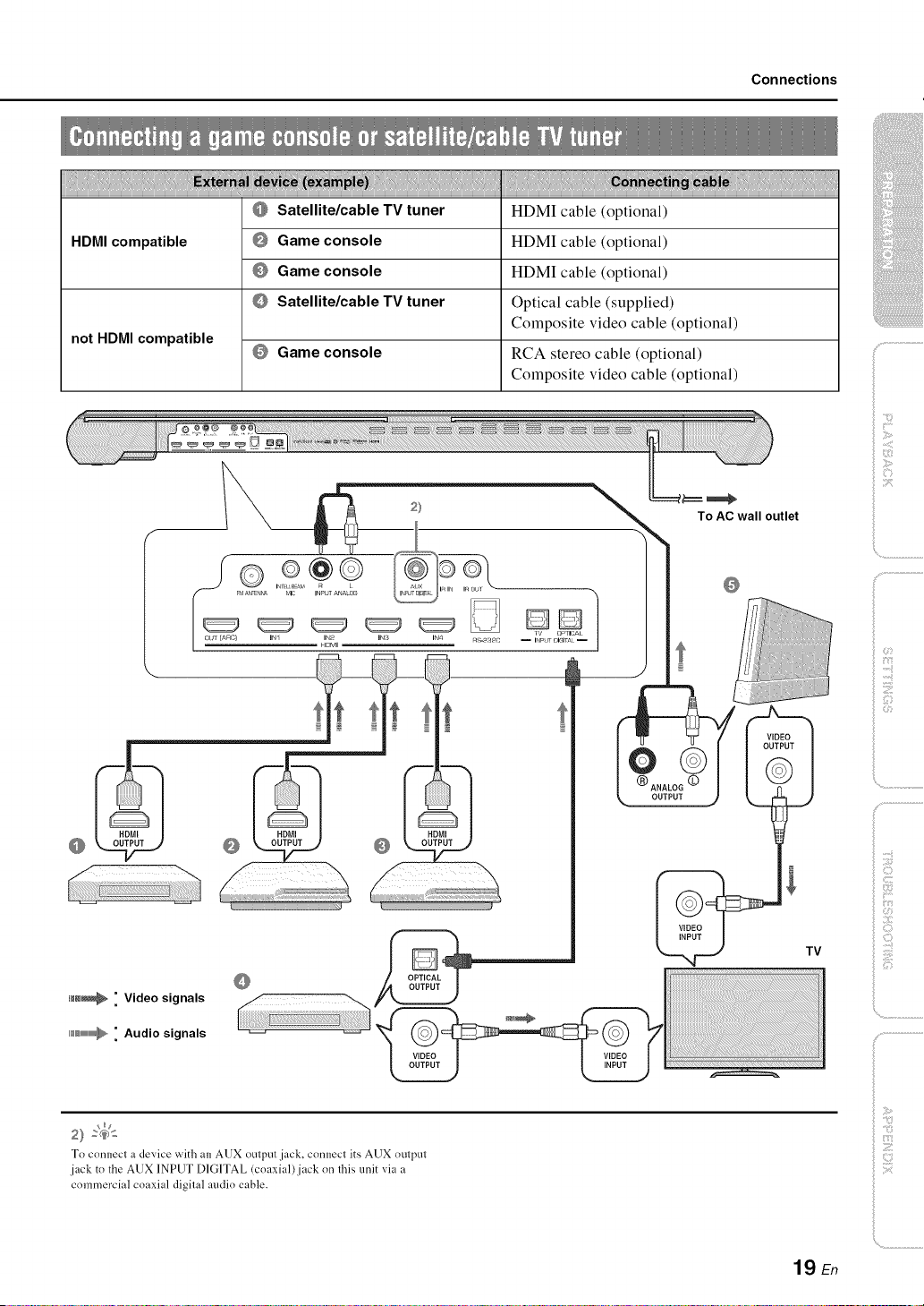
Connections
HDMI compatible
not HDMI compatible
Satellite/cable TV tuner
Game console
Game console
Satellite/cable TV tuner
Game console
HDMI cable (optional)
HDMI cable (optional)
HDMI cable (optional)
Optical cable (supplied)
Composite video cable (optional)
RCA stereo cable (optional)
Composite video cable (optional)
To AC wall outlet
-,\
>
ilii_i_i_iiii_!i!i!iii!!i!_
', ,,iiiiii_'_!_i_iII!............
To connect a device with an AUX output jack, connect its AUX output
jack to the AUX INPUT DIGITAL (coaxial)jack on this unit via a
commercial coaxial digital audio cable.
iiili{_ii_i_!!!i!iii!
19 En
Connections
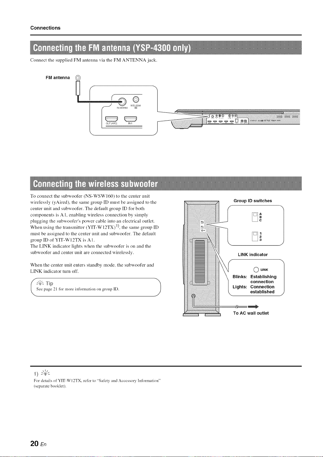
Connect the supplied FM antenna via the FM ANTENNA jack.
FM antenna
\
To connect the subwoofer (NS-WSWI60) to the center unit
wirelessly (yAired), the same group ID must be assigned to the
center unit and subwoofer. The default group ID for both
components is A 1, enabling wireless connection by simply
plugging the subwoofer's power cable into an electrical outlet.
When using the transmitter (Y[T-WI2TX) 1},the same group ID
must be assigned to the center unit and subwoofer. The default
group ID of YIT-WI 2TX is A 1.
The LINK indicator lights when the subwoofer is on and the
subwoofer and center unit are connected wirelessly.
When the center unit enters standby mode, the subwoofer and
LINK indicator turn off.
?,_'- Tip
ee page 21 t:_rmore int:_rmalionon group ID.
)
Group ID switches
LINK indicator
O LINK
Blinks: Establishing
connection
Lights: Connection
established
To AC wall outlet
For details of"YIT-WI2TX, re[er lo "Safety and Accessory hfformation"
(separale booklet).
20 En
Initial settings
Yamaha's proprietary yAired technology enables the wireless
connection of the center unit and subwoofer. Wireless connection
of the subwoofer allows for subwoofer installation without
concern for cables. When the transmitter (YIT-WI 2TX) is used,
iPods or computers call be connected wirelessly to play music
stored on these devices through this unit.
For details of YIT-WI2TX, refer to "Safety and Accessory
[nformatiou" (separate booklet).
When playing content fi'om a TV or Blu-ray disc player, the
center unit transmits audio signals that are received by the
subwoofer. When YIT-WI2TX is used to play songs stored on an
iPod or computer, YIT-WI2TX sends audio signals that are
received by the center unit and subwoofer.
The same group [D must be assigned to all components. By
default, the ceuter unit, subwoofer, aud YIT-WI2TX are assigned
a group ID of A 1. This group ID does uot ueed to be chauged.
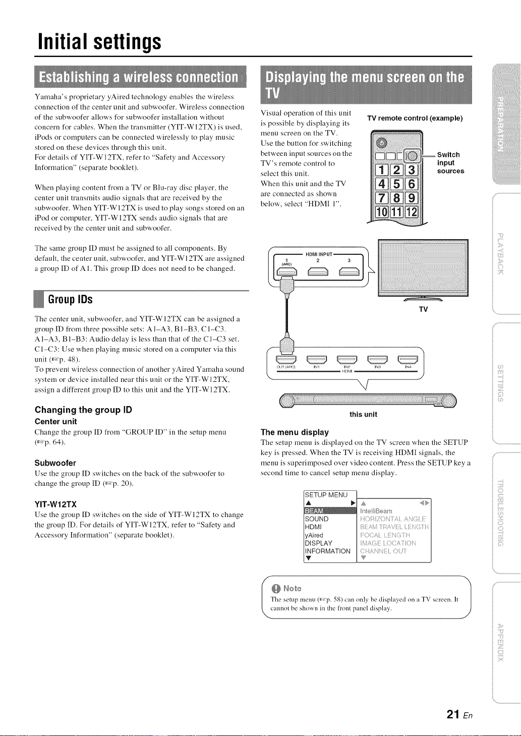
Visual operation of this unit
is possible by displaying its
menu screen on the TV.
Use the button for switching
between input sources on the
TV's remote control to
select this unit.
When this unit and the TV
are connected as shown
below', select "HDM[ 1".
TV remote control (example)
_ Switch
'snoPuUtces
GrouplDs
The center unit, subwoofer, and YIT-Wl2TX can be assigned a
group ID from three possible sets: A I-A3, B I-B3, C 1-C3.
AI-A3, BI-B3: Audio delay is less than that of the C1-C3 set.
C1-C3: Use when playing music stored on a computer via this
unit ff_p. 48).
To prevent wireless connection of another yAired Yamaha sound
system or device installed near this unit or the YIT-WI2TX,
assign a different group ID to this unit and the YIT-WI2TX.
Changing the group ID
Center unit
Change the group ID from "GROUP ID" in the setup meuu
ff_p. 64).
Subwoofer
Use the group [D switches on the back of the subwoofer to
change the group [D ff_p. 20).
YIT-W12TX
Use the group [D switches on the side of YIT-Wl2TX to change
the group ID. For details of YIT-WI2TX, refer to "Safety and
Accessory [nformatiou" (separate booklet).
TV
IN1 IN2 INS
H_MI
,,,/
this unit
The menu display
The setup meuu is displayed on the TV screeu when the SETUP
key is pressed. When the TV is receiving HDM[ signals, the
menu is superimposed over video content. Press the SETUP key a
second time to cancel setup meuu display.
SETUP MENU
]HDMI
lyAired
]DISPLAY
I_FORMATION
he setup tnenu (_Tp. 58) can only be displayed on a TV screen. It
It Note 1
annol be shown in the lront panel display.
21 En
Initial settings
At'it
SETUP
ENTER
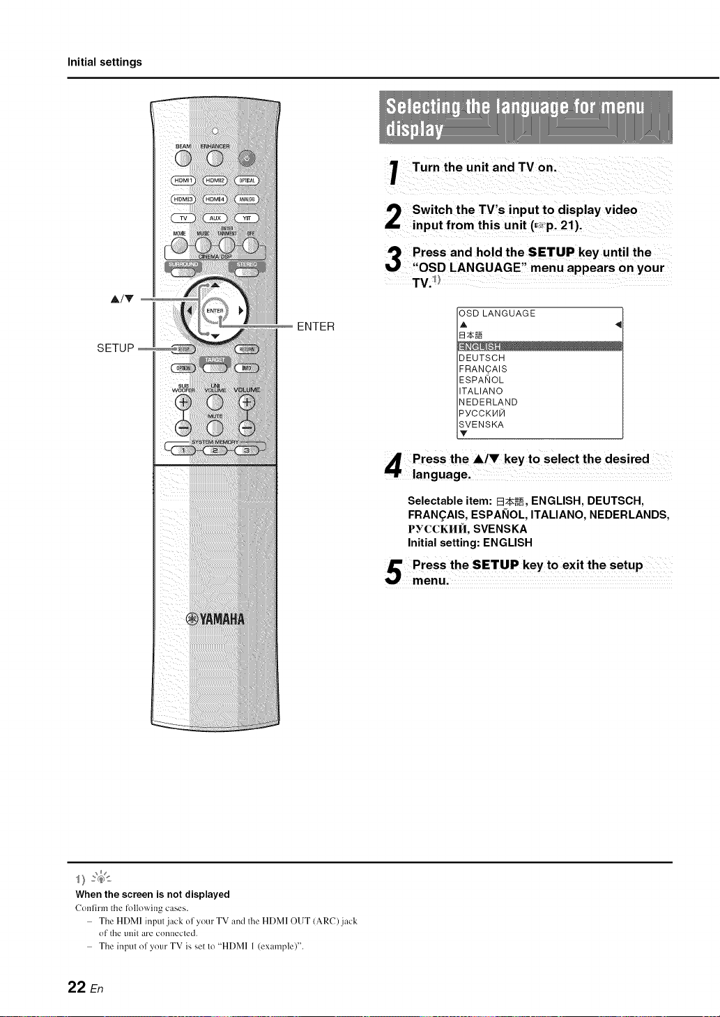
Turn the unit and TV on.
Switch the TV's input to display video
input from this unit (_,p.21).
J'_ Pressand hold the SETUP key until the
"OSD LANGUAGE" menu appears on your
TV._
OSDLANGUAGE
A
B_N
DEUTSCH
FRAN_AIS
ESPANOL
ITALIANO
NEDERLAND
PYCCKHN
SVENSKA
Y
When the screen is not displayed
Confirm the following cases.
The HDMI input jack of your TV and the HDMI OUT (ARC) jack
of the unit are connected.
The input of your TV is set to "HDMI 1 (example)".
Selectable item: E_2k_, ENGLISH, DEUTSCH,
FRAN(_AIS, ESPANOL, ITALIANO, NEDERLANDS,
PYCCKI/II_I, SVENSKA
Initial setting: ENGLISH
22 En
Due to differences in room sizes and shapes, positioning of this
unit, and the lifestyle of users, settings for each channel must be
adjusted in order for this unit to provide the optimal listening
experience.
This unit is equipped with IntelliBearn, which automatically
adjusts settings for each channel. IntelliBearn offers two features,
"beam optimization" and "sound optimization".
Beam optimization:
This feature optimizes the beam angle so that the parameter best
matches your listening environment.
Sound optimization:
This feature optimizes the beam delay, volume, and quality so
that the parameters best match your listening environment.
This unit performs these two automatic optimizations with the aid
of the supplied [ntelliBeam microphone.2)
Initial settings
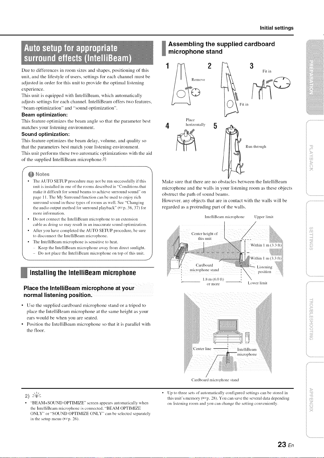
Assembling the supplied cardboard
microphone stand
Place
4 horizontally 5
Run through
f
f
f
• The AUTO SETUP procedure nmy not be run successffflly if this
unit is installed in one of the rooms described in "Conditions that
make it difficult lor sotmd beams to achieve surround sound" on
page 11. The My SurromM fimction can be used to enjoy rich
surround sound in these types of rooms as well. See "Changing
the audio output method tk_rsurround playback" 0_p. 36, 37) lor
more information.
• Do not connect the lntelliBeam microphone to an extension
cable as doing so may result in an inaccurate sound optimization.
• After you have completed the AUTO SETUP procedure, be sure
to disconnect the lntelliBeam microphone.
• The IntelliBeam microphone is sensitive to beat.
Keep the lntelliBeam microphone away from direct sunlight.
Do not place the lntelliBeam microphone on top of this unit.
Installingthe IntelliBeammicrophone
Place the IntelliBeam microphone at your
normal listening position.
• Use the supplied cardboard microphone stand or a tripod to
place the [ntelliBeam microphone at the same height as your
ears would be when you are seated.
• Position the [ntelliBeam microphone so that it is parallel with
the floor.
Make sure that there are no obstacles between the [ntelliBeam
microphone and the walls in your listening room as these objects
obstruct the path of sound beams.
However, any objects that are in contact with the walls will be
regarded as a protruding part of the walls.
llltelliBeam nficrophone Upper limit
:h_of
Within 1 m i3 3 iii!i
J
:Jj : t i' wi
rd =
st lnd_
1.8 m (6.0 fl) __ Lower limil
)
f i;_{:_¸¸
i
• "BEAM+SOUND OPTIMIZE" screen appears automatically when
the lntelliBeam microphone is connected. "BEAM OPTIMIZE
ONLY" or "SOUND OPTIMIZE ONLY" can be selected separately
in the setup menu(_ p. 26).
CaMboard microphone stand
• Up to three sels of aulornatically configured sellings can be stored in
lhis unil's memory (_p. 28). You can save the several dala depending
on lislening room and you can change lhe setting conveniently.
23 En
Z
Initial settings
ENTER
_RETURN
Using AUTO SETUP (IntelliBeam)
f-
• It is normal for loud test tones to be ot/tput dm'ing the AUTO
SETUP procedure. Make sure that there are no children around
in the listening room while the ALTTOSETUP procedure is in
progress.
• If there are curtains in ynur listening room, we recnmmend
lollowing the procedure below.
1 Open the curtains to improve snund reflectinn.
2 Run "BEAM OPTIMIZE ONLY" (_,p. 26).
3 Close the cm'tains.
4 Run "SOUND OPTIMIZE ONLY" (_p. 26).
• Make sure that your listening room is as quiet as possible. For
accurate measurement, turn oft" air conditioner or other devices
that make noises.
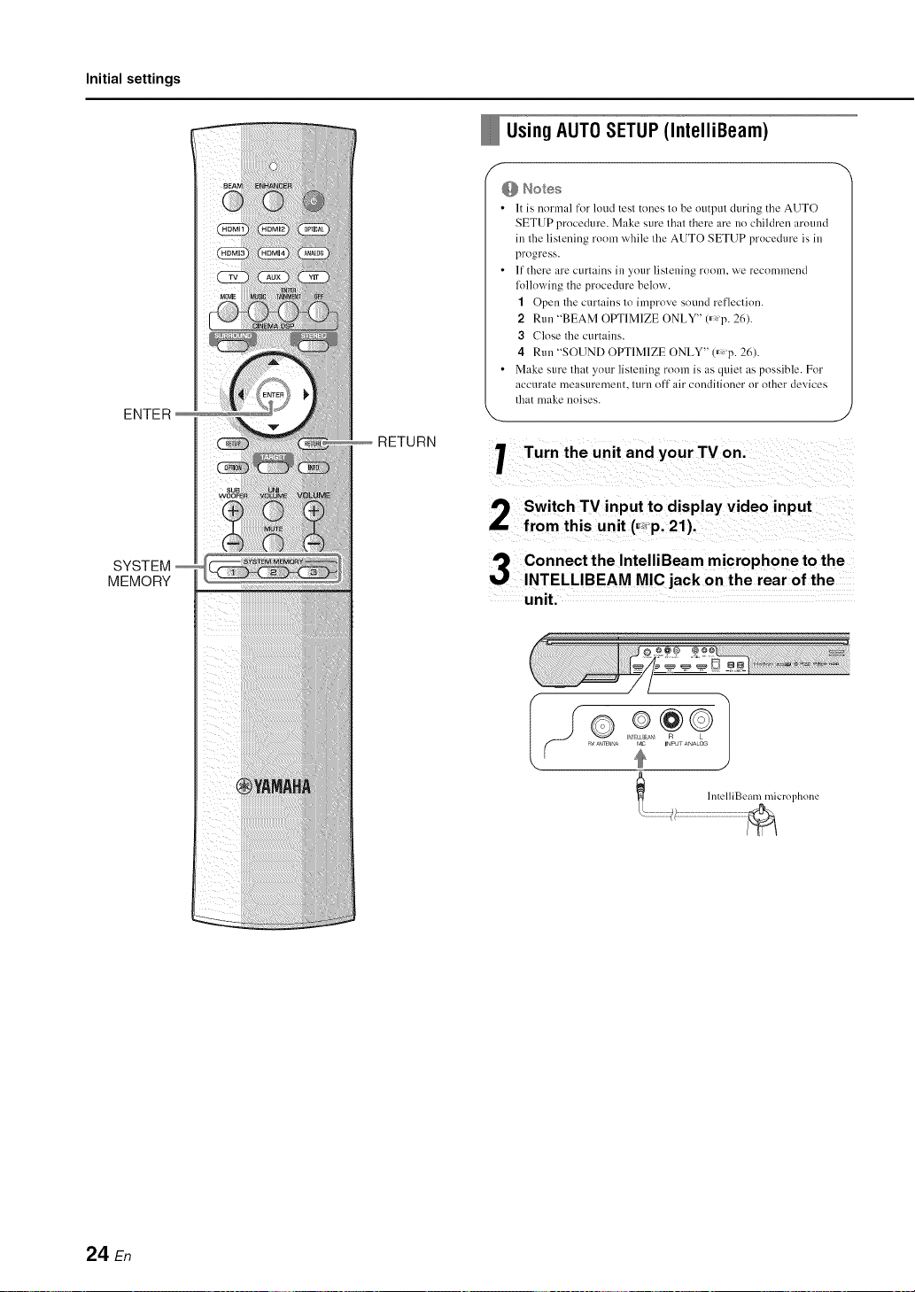
Turn the unit and your TV on.
Switch TV input to display video input
from this unit (_p. 21).
SYSTEM
MEMORY
Connect the IntelliBeam microphone to the
INTELLIBEAM MIC jack on the rear of the
unit.
II ® 2¢01
'c "' •_,' _'_][NNA I IMI UNPU ANALOG
24 En
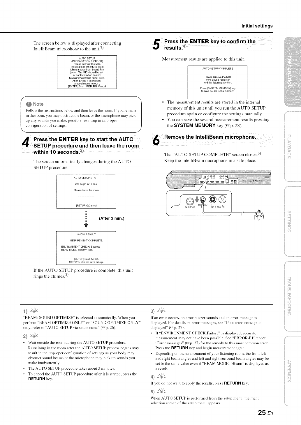
The screen below' is displayed after connecting
[ntelliBeam microphone to the unit. 1)
AUTO SETUP
(PREPARATION & CHECK)
Please connect the MIC.
Please place the MIC at [east
1.8m/6tt away from Sound Pro-
jector. The MIC should be set
at ear level when seated.
Measurement takes about 3rain.
After [ENTER[ is pressed,
please leave the room.
[ENTER]:Start [RETURN]:Cancel
in lhe room, you may obslruc/the beam, or the microphone may pick
up any sOUnLIsyou make, possibly resulling in improper
Follovv' the inslructions below anLIthen leave the room. If you remain /
cnnfiguralion ol sellings.
Initial settings
Measurement results are applied to this unit.
AUTO SETUP COMPLETE
Please remove the MIC
from Sound Prolector
and the listening position.
Press [SYSTEM MEMORY1 key
to save set-up in the memory.
• The measurement results are stored in the internal
memory of this unit until you run the AUTO SETUP
procedure again or configure the settings manually.
• You can save the several measurement results pressing
the SYSTEM MEMORY key (_<p. 28).
/. .................
The screen automatically changes during the AUTO
SETUP procedure.
AUTO SETUP START
Wi[[ begin in 10 sec.
Please leave the room
[RETURN]:Cancel
m
(After 3 min.)
=
SHOW RESULT
MESUREMENT COMPLETE.
ENVIRONMENT CHECK: Success
BEAM MODE: 5Beam/Plus2
[ENTER]:Save set-up.
[RETURNI:Do not save set-up.
If the AUTO SETUP procedure is complete, this unit
rings the chimes. 3}
6 Remove the IntelliBeam microphone i
The "AUTO SETUP COMPLETE" screen closes. 5}
Keep the [ntelliBeam microphone in a safe place.
i>
ilii_i_i_iiii_!i!i!iii!!i!_
', ,,iiiiii_'_!_i_iII!............
)
"BEAM+SOUND OPTIMIZE" is selected automatically. When you
perlorm "BEAM OPTIMIZE ONLY" or "SOUND OPTIMIZE ONLY"
only, relier to "AUTO SETUP via setup menu" (_,p. 26).
_ng
• Wait outside the room during the AUTO SETUP procedure.
Remaining in the room after the AUTO SETUP process begins may
result in the improper configuration of settings as your body may
obstruct sound beams or the microphone may pick up sounds you
make inadvertently.
• The AUTO SETUP procedure takes about 3 minutes.
• To cancel the AUTO SETUP procedure after it is started, press the
RETURN key.
II an error occtlrs, all error bLizzer sounds and an error message is
displayed. For details on error messages, see "If an error message is
displayed" <_p. 27).
• lf"ENV1RONMENT CHECK:Faihu'e" is displayed, accurale
measuremem may not have been possible. See "ERROR-El" uncler
"Error messages" 0_ p. 27) for the remedy 1o Ihis mosl common error.
Press the RETURN key, and begin measurement again.
• Depencling on lhe environmem ol your lislening room, lhe firont lelt
and righl beam angles ancl leR and righl surround beam angles may be
sel to Ihe same value even it""BEAM MODE :5Beam" is displayed as
a result.
_ng
11you do not warn to apply' the resulls, press RETURN key,.
When AUTO SETUP is performed from the setup menu. the menu
selection screen ollhe setup menu appears.
25 En
Z
Initial settings
At'it
SETUP
Fiiiiiiiiiiiiiiiiiiiiiiiiiiiill
ENTER
RETURN
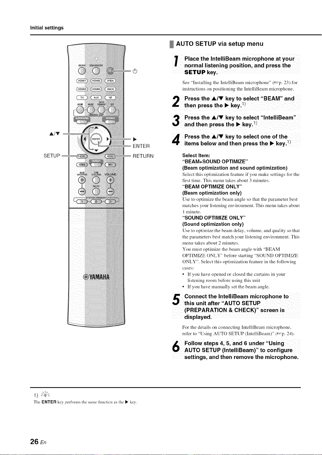
AUTO SETUP via setup menu
1 Place the IntelliBeam microphone at your
normal listening position, and press the
SETUP key.
See "Installing the [ntelliBeam microphone" (,_xp. 23) for
instructions on positioning the IntelliBeam microphone.
Select Item:
"BEAM+SOUND OPTIMIZE"
(Beam optimization and sound optimization)
Select this optimization feature if you make settings for the
first time. This menu takes about 3 minutes.
"BEAM OPTIMIZE ONLY"
(Beam optimization only)
Use to optimize the beam angle so that the parameter best
matches your listening environment. This menu takes about
1 minute.
"SOUND OPTIMIZE ONLY"
(Sound optimization only)
Use to optimize the beam delay, volume, and quality so that
the paraineters best match your listening environment. This
menu takes about 2 minutes.
You must optimize the beam angle with "BEAM
OPTIM[ZE ONLY" before starting "SOUND OPTIM[ZE
ONLY". Select this optimization feature in the following
cases:
• If you have opened or closed the curtains in your
listening room before using this unit
• If you have manually set the beam angle.
The ENTER key, performs lhe same function as lhe • key.
26 En
(PREPARATION & CHECK)" screen is ......
displayed. .........
For the details on connecting [ntelliBeam microphone,
refer to 'Using AUTO SETUP (IntelliBeam)" (_,:'p. 24).
Follow steps 4, and 6 under :fUsing
AUTO SETUP (IntelliBeam)' to configure
settings, and then remove the microphone.
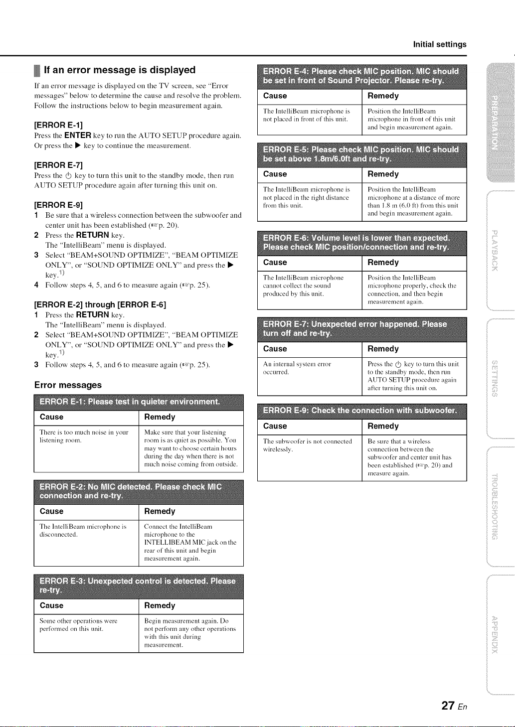
If an error message is displayed
If all error message is displayed on the TV screen, see "Error
messages" below' to determine the cause and resolve the problem.
Follow' the instructions below' to begin measurement again.
[ERROR E-l]
Press the ENTER key to run the AUTO SETUP procedure again.
Or press the • key to continue the measurement.
Cause
The hnelliBeam microphone is
not placed in h'ont ol this unit.
Initial settings
Remedy
Position lhe I ntelliBeam
microl?hone in fl'ont ol 1his unit
and begin measurement again.
[ERROR E-7]
Press the (}) key to turu this uuit to the standby mode, then run
AUTO SETUP procedure again after turning this unit on.
[ERROR E-9]
1 Be sure that a wireless connection betweeu the subwoofer and
center unit has been established (_: p. 20).
2 Press the RETURN key.
The "IntelliBeam" menu is displayed.
3 Select "BEAM+SOUND OPTIM[ZE", "BEAM OPTIM[ZE
ONLY", or "SOUND OPTIM[ZE ONLY" and press the •
key. I)
4 Follow' steps 4, 5, and 6 to measure again (_:p. 25).
[ERROR E-2] through [ERROR E-6]
1 Press the RETURN key.
The "IutelliBeam" menu is displayed.
2 Select "BEAM+SOUND OPTIMIZE", "BEAM OPTIMIZE
ONLY", or "SOUND OPTIMIZE ONLY" and press the •
key. I)
3 Follow' steps 4, 5, and 6 to measure again (_:p. 25).
Error messages
Cause Remedy
There is too much noise in _our Make sure that 2tour listening
listening room. room is as quiet as possible. You
may want to choose certain hours
during the day when there is not
much noise coming from outside.
Cause Remedy
The lntelliBeam microphone is Position the hltelliBeam
not placed in the right distance microphone at a distance of more
from this unit. than 1.8 m (6.0 1:)from this unit
Cause Remedy
The lntelliBeam microphone Position the lntelliBeam
cannot collect the sound microphone properly, check the
produced by this unit. connection, and then begin
Cause Remedy
An internal s}stem error Press the @ key to mrn this unit
occurred, to the standby mode, then run
Cause Remedy
The s[]hx_roo]_ris not connected Be sure that at vvrireless
wirelessly, colmection between the
and begin measurement again.
measurement again.
AUTO SETUP procedure again
after turlfing this unit on.
subwooli_r and center unit has
been established 0_ p. 20) and
measure again.
(3
f
)
ii _i_i;iiiiiiii
Cause Remedy
The lntelliBeam microphone is Connect the lntelliBeam
disconnected, microphone to the
Cause Remedy
Some other operations were Begin measurement again. Do
performed on this unit. not perform any other operations
1NTELL1BEAM MlCjack on the
rear of this unit and begin
measurement again.
with this unit during
measurement.
_ :7
Z
27 En
Initial settings
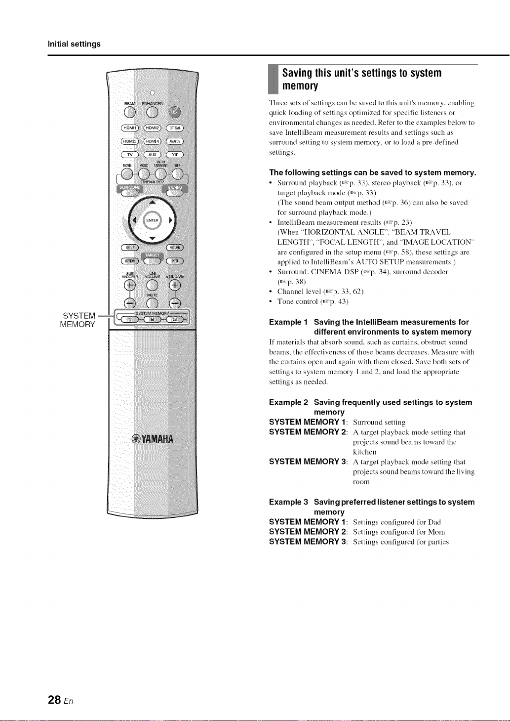
SYSTEM
MEMORY
Savingthisunit'ssettingstosystem
memo_
Three sets of settings can be saved to this unit's memory, enabling
quick loading of settings optimized for specific listeners or
environmental changes as needed. Refer to the examples below' to
save [ntelliBeam measurement results and settings such as
surround setting to system memory, or to load a pre-defined
settings.
The following settings can be saved to system memory.
• Surround playback (_ p. 33), stereo playback (_ p. 33), or
target playback rnode (_,_p. 33)
(The sound beam output method (_,_p. 36) can also be saved
for surround playback rnode.)
• [ntelliBeam measurernent results (_p. 23)
(When "HOR[ZONTAL ANGLE", "BEAM TRAVEL
LENGTH", "FOCAL LENGTH", and "IMAGE LOCATION"
are configured in the setup rnenu (_,_p. 58), these settings are
applied to IntelliBearn's AUTO SETUP measurements.)
• Surround: CINEMA DSP (_,_p. 34), surround decoder
(_ p. 38)
• Channel level (_:p. 33, 62)
• Tone control (_,:p. 43)
Example 1 Saving the IntelliBeam measurements for
different environments to system memory
[f materials that absorb sound, such as curtains, obstruct sound
beams, the effectiveness of those beams decreases. Measure with
the curtains open and again with them closed. Save both sets of
settings to system memory 1 and 2, and load the appropriate
settings as needed.
Example 2 Saving frequently used settings to system
SYSTEM MEMORY 1: Surround setting
memory
SYSTEM MEMORY2: A target playback mode setting that
projects sound beams toward the
kitchen
SYSTEM MEMORY 3: A target playback mode setting that
projects sound beams toward the living
room
Example 3 Saving preferred listener settings to system
memory
SYSTEM MEMORY 1: Settings configured for Dad
SYSTEM MEMORY 2: Settings configured for Morn
SYSTEM MEMORY 3: Settings configured for parties
28 En
Initial settings
Saving settings to system memory
7 Hold down the SYSTEM, MEMORY 1,:2,
or 3 key until M1Save? ;'M2Save? ;O r
,M3 Save?", corresponding to the button
pressed, is displayed,
I') Press the same SYSTEM MEMORY key
again])
When the SYSTEM MEMORY 1 key is pressed, "M 1
Saving" is displayed, and settings are saved.
Loading settings
1 Press theSYSTEM MEMORY 112' or3
key corresponding to settings to be
loaded.
If the SYSTEM MEMORY 1 key is pressed, "MI
Load'?" will be displayed.
9 Press the same SYSTEM MEMORY key
i.. again.
When the SYSTEM MEMORY 1 key is pressed, "MI
Loading" is displayed, and settings are loaded.
ilii_i_i_iiii_!i!i!iii!!i!_
', ,,iii;ii_'_!_i_iII!............
• If system settings are already stored in the selected memory number,
this unit overwrites the old settings.
• The memory ftmction cannot be set when "MEMORY PROTECT" is
set to "ON" in the advanced setup melm (_,p. 66).
29 En
Initial settings
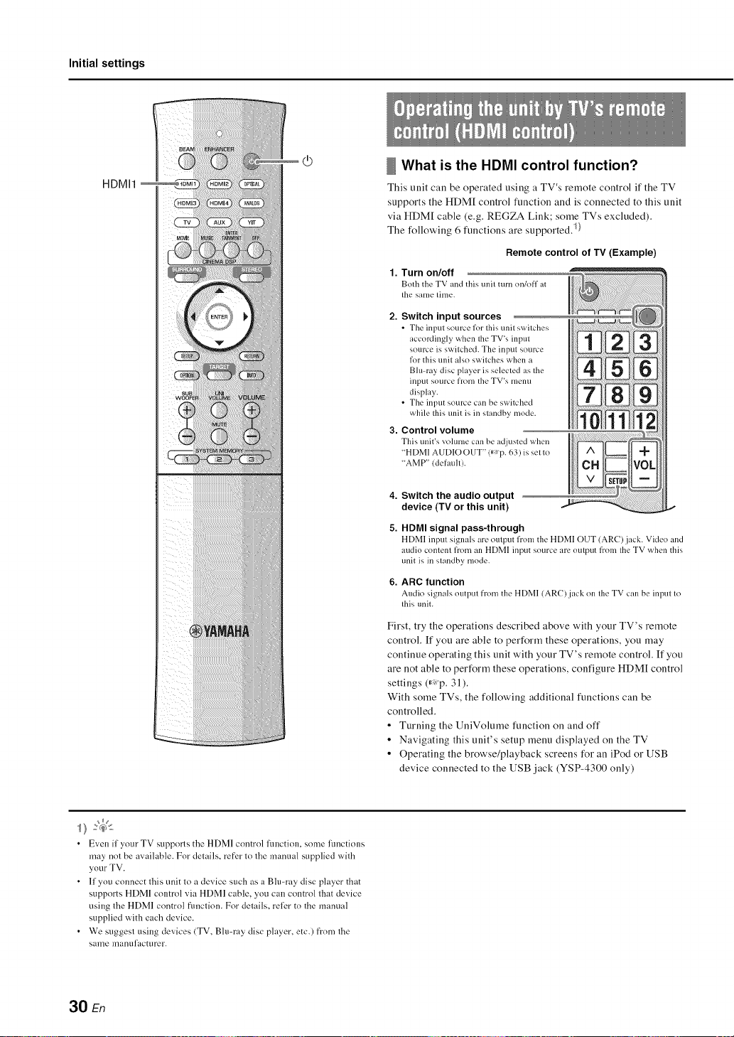
HDMI1
What is the HDMI control function?
This trait call be operated using a TV's reruote control if the TV
supports the HDM[ control ftmction and is connected to this unit
via HDM[ cable (e.g. REGZA Link; some TVs excluded).
The following 6 ftmctions are supported)}
Remote control of TV (Example)
1.
Turn on/off
Both the TV and this/mit turn on/off at
tile same time.
2. Switch input sources
• The input source lklr this unit switches
accordingly when the TV's input
source is switched. The input source
lkw this unit also switches when a
Blu-ray disc player is selected as the
input source from the TV's menu
display.
• The input source can be switched
while this unit is in standby mode.
3. Control volume
This unit's volume can bc ad.justcd when
"HDMI AUDIO OUT" 0" P. 63) is set to
"AMP" (default).
• Even if your TV supports the HDMI control Rmction, some functions
may not be available. For details, refer to the manual supplied with
your TV.
• If you connect this unit to a device such as a Blu-ray disc player that
supports HDMI control via HDMI cable, you can control that device
using the HDMI control flmction. For details, relier to the manual
supplied with each device.
• We suggest using devices (TV, Bh>ray disc player, etc.) fi'om the
same manufacturer.
4. Switch the audio output
device (TV or this unit)
5. HDMI signal pass-through
HDMI input signals are output from the HDMI OUT (ARC)jack. Video and
audio content from an HDMI input source art.' output from tile TV when this
unit is in standby mode.
6.
ARC function
Audio signals output from the HDMI (AR()jack on tilt' TV can bc input to
this unit.
First, try the operations described above with your TV's remote
control. If you are able to perform these operations, you may
continue operating this unit with your TV's remote control. If you
are not able to perform these operations, configure HDM[ control
settings (_: p. 31 ).
With some TVs, the following additional functions can be
controlled.
• Turning the UuiVolume function on and off
• Navigating this unit's setup menu displayed on the TV
• Operating the browse/playback screens for an iPod or USB
device connected to the USB jack (YSP-4300 only)
30 En
 Loading...