

Yamaha YSP-600 User Manual [de]

YSP-600
G
Digital Sound Projector
TM
Système Acoustique Numérique
OWNER’S MANUAL
MODE D’EMPLOI
BEDIENUNGSANLEITUNG
BRUKSANVISNING
GEBRUIKSAANWIJZING
ИНСТРУКЦИЯ ПО ЭКСПЛУАТАЦИИ

CAUTION: READ THIS BEFORE OPERATING THIS UNIT.
Caution: Read this before operating this unit.
To assure the finest performance, please read this manual
1
carefully. Keep it in a safe place for future reference.
2 Install this sound system in a well ventilated, cool, dry, clean
place with at least 5 cm (2 in) of space above (or below) this unit
– away from direct sunlight, heat sources, vibration, dust,
moisture, and/or cold.
3 Locate this unit away from other electrical appliances, motors, or
transformers to avoid humming sounds.
4 Do not expose this unit to sudden temperature changes from cold
to hot, and do not locate this unit in an environment with high
humidity (i.e. a room with a humidifier) to prevent condensation
inside this unit, which may cause an electrical shock, fire,
damage to this unit, and/or personal injury.
5 Avoid installing this unit where foreign object may fall onto this
unit and/or this unit may be exposed to liquid dripping or
splashing. On the top of this unit, do not place:
– Other components, as they may cause damage and/or
discoloration on the surface of this unit.
– Burning objects (i.e. candles), as they may cause fire, damage
to this unit, and/or personal injury.
– Containers with liquid in them, as they may fall and liquid may
cause electrical shock to the user and/or damage to this unit.
6 Do not cover this unit with a newspaper, tablecloth, curtain, etc.
in order not to obstruct heat radiation. If the temperature inside
this unit rises, it may cause fire, damage to this unit, and/or
personal injury.
7 Do not plug in this unit to a wall outlet until all connections are
complete.
8 Do not operate this unit upside-down. It may overheat, possibly
causing damage.
9 Do not use force on switches, knobs and/or cords.
10 When disconnecting the power supply cable from the wall outlet,
grasp the plug; do not pull the cable.
11 Do not clean this unit with chemical solvents; this might damage
the finish. Use a clean, dry cloth.
12 Only voltage specified on this unit must be used. Using this unit
with a higher voltage than specified is dangerous and may cause
fire, damage to this unit, and/or personal injury. Yamaha will not
be held responsible for any damage resulting from use of this unit
with a voltage other than specified.
13
To prevent damage by lightning, keep the power supply cable
disconnected from a wall outlet or this unit during a lightning storm.
14 Do not attempt to modify or fix this unit. Contact qualified
Yamaha service personnel when any service is needed.
The cabinet should never be opened for any reasons.
15 When not planning to use this unit for long periods of time (i.e.
vacation), disconnect the power supply cable from the wall
outlet.
16 Be sure to read the “Troubleshooting” section on common
operating errors before concluding that this unit is faulty.
17 Before moving this unit, press STANDBY/ON to set this unit in
standby mode, and disconnect the power supply cable from the
wall outlet.
18 Condensation will form when the surrounding temperature
changes suddenly. Disconnect the power supply cable from the
outlet, then leave the unit alone.
19 When using the unit for a long time, the unit may become warm.
Turn the power off, then leave the unit alone for cooling.
20 Install this unit near the AC outlet and where the AC power plug
can be reached easily.
21 The batteries shall not be exposed to excessive heat such as
sunshine, fire or the like.
WAR NING
TO REDUCE THE RISK OF FIRE OR ELECTRIC SHOCK, DO
NOT EXPOSE THIS UNIT TO RAIN OR MOISTURE.
This unit is not disconnected from the AC power source as long as
it is connected to the AC wall outlet, even if this unit itself is
turned off by STANDBY/ON. This state is called the standby
mode. In this state, this unit is designed to consume a very small
quantity of power.
FOR U.K. CUSTOMERS
If the socket outlets in the home are not suitable for the plug
supplied with this appliance, it should be cut off and an
appropriate 3 pin plug fitted. For details, refer to the instructions
described below. Note that the plug severed from the mains lead
must be destroyed, as a plug with bared flexible cord is hazardous
if engaged in a live socket outlet.
IMPORTANT
THE WIRES IN MAINS LEAD ARE COLOURED IN
ACCORDANCE WITH THE FOLLOWING CODE:
Blue: NEUTRAL
Brown: LIVE
As the colours of the wires in the mains lead of this apparatus may
not correspond with the coloured markings identifying the terminals
in your plug, proceed as follows:
The wire which is coloured BLUE must be connected to the terminal
which is marked with the letter N or coloured BLACK. The wire
which is coloured BROWN must be connected to the terminal which
is marked with the letter L or coloured RED. Make sure that neither
core is connected to the earth terminal of the three pin plug.
CAUTION
Danger of explosion if battery is incorrectly replaced. Replace
only with the same or equivalent type.
CAUTION
Use of controls or adjustments or performance of procedures other
than those specified herein may result in hazardous radiation
exposure.
This symbol mark is according to the
EU directive 2002/96/EC.
This symbol mark means that electrical
and electronic equipment, at their endof-life, should be disposed of separately
from your household waste.
Please act according to your local rules
and do not dispose of your old products
with your normal household waste.
i En

Contents
INTRODUCTION
Overview................................................................. 2
Features .................................................................. 3
Using this manual .................................................. 5
Supplied accessories .............................................. 6
Controls and functions .......................................... 7
Front panel ................................................................ 7
Front panel display ................................................... 8
Rear panel ................................................................. 9
Remote control........................................................ 10
PREPARATION
Installation............................................................ 13
Before installing this unit........................................ 13
Installing this unit ................................................... 13
Connections .......................................................... 16
Before connecting components............................... 17
Connections using HDMI cables ............................ 18
Connecting a TV..................................................... 19
Connecting a DVD player/recorder ........................ 20
Connecting a digital satellite tuner or
a cable TV tuner ................................................. 21
Connecting a digital airwave tuner ......................... 22
Connecting a VCR.................................................. 23
Connecting other external components .................. 24
Connecting a subwoofer ......................................... 25
Connecting the AC power supply cable ................. 26
SETUP
Getting started ..................................................... 27
Installing batteries in the remote control ................ 27
Operation range of the remote control .................... 27
Turning on this unit or
setting it to the standby mode............................. 28
Using SET MENU................................................ 29
Displaying the OSD (on-screen display) ................ 29
The flow chart of SET MENU................................ 30
Changing OSD language..................................... 31
AUTO SETUP (IntelliBeam) .............................. 32
The flow chart of AUTO SETUP ........................... 32
Installing the IntelliBeam microphone ................... 33
Using AUTO SETUP (IntelliBeam) ....................... 34
Using the system memory ................................... 39
Convenient usage of the system memory ............... 39
Saving settings........................................................ 39
Loading settings...................................................... 40
Enjoying stereo sound .......................................... 51
Playing back sound clearly (My Beam).............. 52
Using auto-adjust function...................................... 52
Using manual-adjust function................................. 53
Using the volume mode (Night listening
enhancer/TV volume equal mode) .................. 54
Using the sleep timer ............................................ 55
Using the HDMI control feature ......................... 57
ADVANCED OPERATION
MANUAL SETUP ................................................ 58
Using MANUAL SETUP ....................................... 59
BEAM MENU ........................................................ 60
SOUND MENU...................................................... 64
INPUT MENU........................................................ 66
DISPLAY MENU................................................... 69
Adjusting the audio balance ................................ 70
Using the test tone .................................................. 70
Using the audio output being played back.............. 71
Selecting the input mode...................................... 73
Adjusting the system parameters ....................... 74
Using the system parameters .................................. 74
Remote control features....................................... 76
Setting remote control codes .................................. 76
Controlling other components ................................ 77
Using the TV macro ............................................... 80
ADDITIONAL INFORMATION
Troubleshooting.................................................... 82
Glossary................................................................. 85
Index ...................................................................... 87
Specifications ........................................................ 88
List of remote control codes ............................... i
PREPARATIONINTRODUCTION
SETUP
OPERATION
BASIC
OPERATION
ADVANCED
INFORMATION
ADDITIONAL
BASIC OPERATION
Playback ............................................................... 42
Selecting the input source ....................................... 42
Playing back sources............................................... 43
Adjusting the volume.............................................. 44
Enjoying surround sound ................................... 45
5 Beam.................................................................... 45
Stereo plus 3 Beam ................................................. 46
3 Beam.................................................................... 46
My Surround........................................................... 46
Enjoying 2-channel sources in surround sound...... 48
Enjoying TV in surround sound ............................. 49
Adjusting surround mode parameters ..................... 50
English
1 En
Overview
Overview
It is generally accepted that in order to fully enjoy the benefits of surround sound at home, you must endure the agony of
wiring and installing a great number of speakers in the hope that your listening room will give you the same kind of
surround sound experience as your local movie theater.
Yamaha YSP-600 Digital Sound Projector challenges this preconception that complicated speaker setup and troublesome
wiring go hand-in-hand with the enjoyment of multi-channel surround sound.
This slimline unit does away with the need for complicated wiring and installation worries, leaving you with a unit that is
not only easy to set up, but is also capable of reproducing the kind of powerful surround sound you have been waiting for
from its built-in 2 woofers and 16 full-range small speakers.
You can fine-tune the parameters of this unit to adjust the delay time for separate sound beams, resulting in highly
directional sound that comes in on the listening position from all directions.
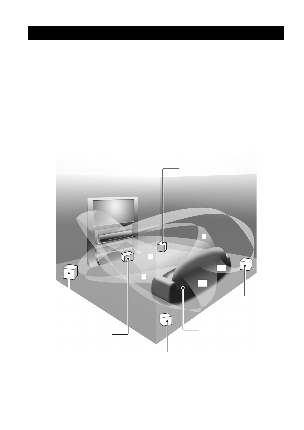
The YSP-600 projects sound beams containing surround sound information for the front right (R), front left (L), surround
right (SR), and surround left (SL) speaker positions, which are reflected off the walls of your listening room before
reaching the actual listening position. With the addition of center (C) sound beams, this Digital Sound Projector creates
true-to-life 5.1-channel surround sound that makes you feel as if there are actual speakers around the room.
Sit back and enjoy the real sound experience of this simple, yet stylish Digital Sound Projector.
Imaginary
front right
speaker
Imaginary
front left
speaker
Imaginary
center
speaker
R
C
SR
L
SL
Imaginary
surround right
speaker
Listening position
Imaginary
surround left
speaker
2 En

Features
Features
Digital Sound Projector™
The Digital Sound Projector technology allows one slim
unit to control and steer multiple channels of sound to
generate multi-channel surround sound, thus eliminates
the need for satellite loudspeakers and cabling normally
associated with conventional surround sound systems.
This unit also employs the beam modes that let you enjoy
the surround sound (5 Beam, Stereo plus 3 Beam and
3 Beam), stereo playback, and My Beam.
My Surround
In addition to the above mentioned beam modes, this unit
is equipped with My Surround beam mode that allows you
to enjoy surround system even in a small listening area.
My Surround is a function integrated and optimized with
DiMAGIC’s Euphony technology and Yamaha’s Beam
reproduction system.
My Beam
This unit employs My Beam that ensures a clear sound in
a noisy environment. You can adjust the beam angle
manually or automatically using the supplied remote
control to the maximum of 30°, rightward and leftward.
HDMI™ (High-Definition Multimedia Interface)
◆ HDMI interface for standard, enhanced, or high-definition
video (including 1080p video signal transmission) as well as
multi-channel digital audio based on HDCP
◆ Simple and easy connections with HDMI supported external
components
◆ Functional link with an HDMI control-compatible TV
Versatile Remote Control
The supplied remote control comes with preset remote
control codes used to control the DVD, Blu-ray, HD DVD
player (recorder), VCR, cable TV tuner, and digital
satellite tuner connected to this unit. In addition, the
remote control is equipped with the macro capability that
enables a series of operations with the press of a single
button.
AUTO SETUP (IntelliBeam)
This unit employs the automatic sound beam and acoustic
optimization technology with the aid of the supplied
IntelliBeam microphone. You can avoid troublesome
listening-based speaker setup and achieve highly accurate
sound beam adjustments that best match your listening
environment.
Compatibility with the Newest Technologies
This unit employs decoders compatible with Dolby
Digital, DTS, Dolby Pro Logic, Dolby Pro Logic II, and
DTS Neo:6.
◆ Dolby Digital
This is the standard audio signal format used on various
digital media such as DVD, Blu-ray, and HD DVD. This
surround technology delivers high-quality digital audio for up
to 5.1 discrete channels to produce a directional and more
realistic effect.
◆ DTS
This is the standard audio signal format used on various
digital media such as DVD, Blu-ray, and HD DVD. This
surround technology delivers high-quality digital audio for up
to 5.1 discrete channels to produce a directional and more
realistic effect.
◆ Dolby Pro Logic
A surround system that takes a 4-channel signal and records it
as a 2-channel signal, then by way of some arithmetic
processing converts back to an independent 4-channel signal
for playback.
◆ Dolby Pro Logic II
Dolby Pro Logic II is an improved technique used to decode
vast numbers of existing Dolby Surround software.
This new technology enables a discrete 5-channel playback
with 2 front left and right channels, 1 center channel, and 2
surround left and right channels (instead of only 1 surround
channel for conventional Pro Logic technology).
◆ DTS Neo:6
This technology decodes the conventional 2-channel sources
for 6-channel playback, enabling playback with the full-range
channels with higher separation. Music mode and Cinema
mode are available to play back music and movie sources
respectively.
INTRODUCTION
3 En
English

Features
The “ ” logo and “IntelliBeam” are trademarks of
Yamaha Corporation.
Manufactured under license from Dolby Laboratories.
“Dolby”, “Pro Logic”, and the double-D symbol are trademarks
of Dolby Laboratories.
“DTS” and “Neo:6” are registered trademarks of DTS, Inc.
“HDMI”, the “HDMI” logo and “High-Definition Multimedia
Interface” are trademarks or registered trademarks of HDMI
Licensing LLC.
Manufactured under license from 1 Ltd. Worldwide patents
applied for.
The “ ” logo and “Digital Sound Projector
™
” are trademarks
of 1 Ltd.
TruBass, SRS and the “ ” symbol are registered trademarks
of SRS Labs, Inc. TruBass technology is incorporated under
license from SRS Labs, Inc.
™
is a trademark of DiMAGIC Co., Ltd.
4 En
Using this manual
Using this manual
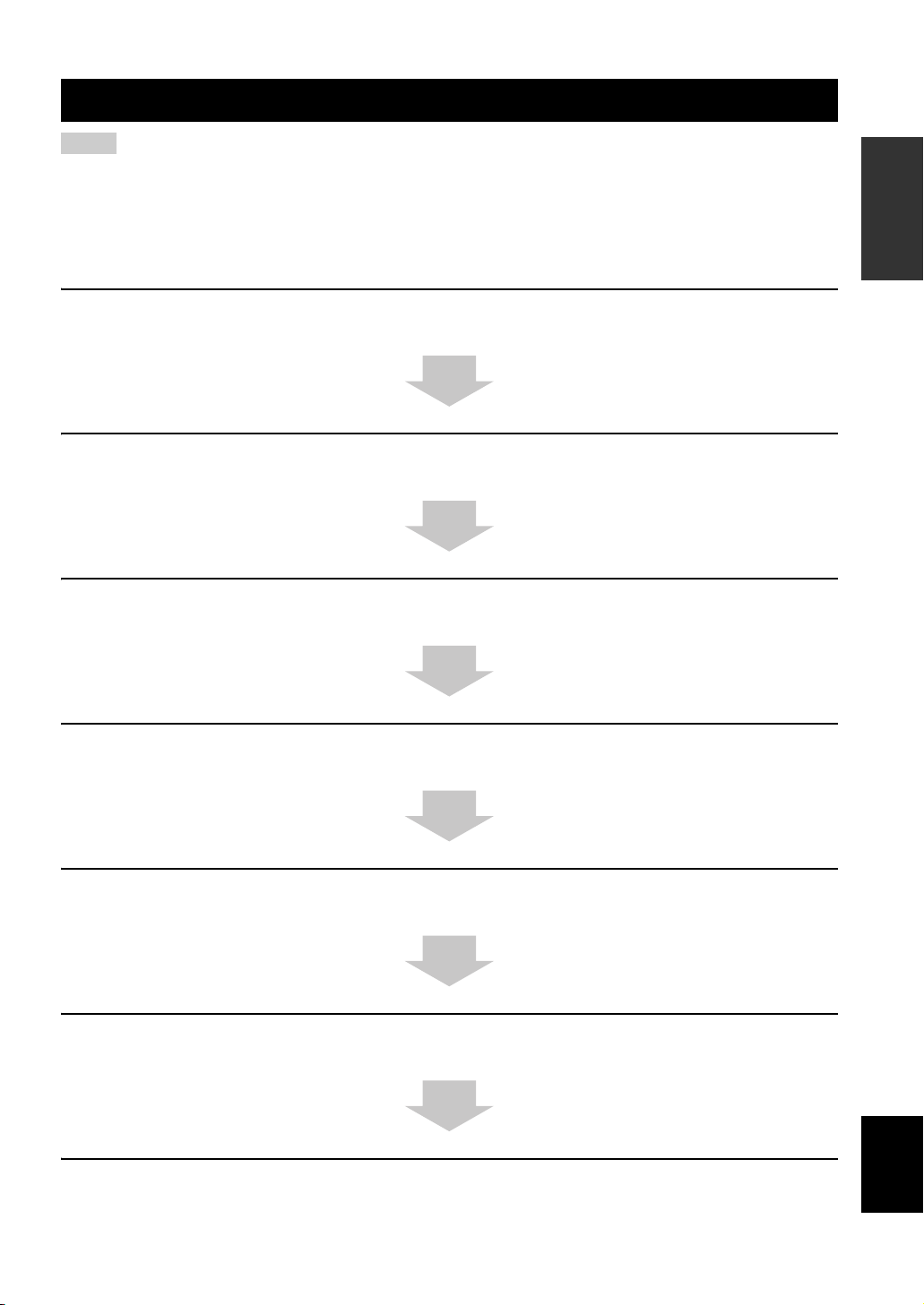
Notes
• This manual describes how to connect and operate this unit. For details regarding the operation of external components, refer to the
supplied owner’s manual for each component.
• Operations in this manual use keys on the supplied remote control of this unit unless otherwise specified.
• y indicates a tip for your operation.
• This manual is printed prior to production. Designs and specifications are subject to change in part as a result of improvements, etc. In
case of differences between the manual and the product, the product has priority.
1 Install this unit in your listening room.
See “Installation” on page 13.
2 Connect this unit to your TV and other external components.
See “Connections” on page 16.
3 Prepare the remote control and turn on the power of this unit.
See “Getting started” on page 27.
INTRODUCTION
4 Run AUTO SETUP.
See “AUTO SETUP (IntelliBeam)” on page 32.
5 Play back a source.
See “Playback” on page 42.
6 Change the beam modes.
See “Enjoying surround sound” on page 45.
If you want to make additional settings
and adjustments
7 Run MANUAL SETUP to fine-tune settings and/or set remote control codes.
See “MANUAL SETUP” on page 58 and “Remote control features” on page 76.
English
5 En
Supplied accessories
Supplied accessories
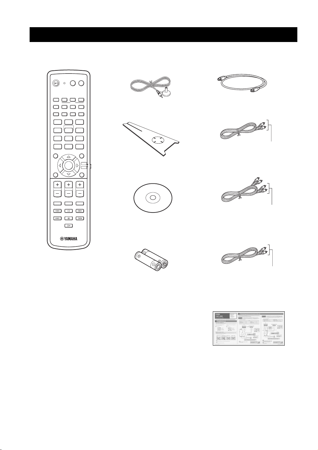
Check that you have received all of the following parts.
Remote control (×1)
POWERPOWERSTANDBY/ON
AV
TV
VCR DVD
STB AUX
TV
MACRO
INPUT2INPUT1
TV
AUTO
SETUP
SLEEP
INPUTMODE
VOL MODE
5BEAM ST+3BEAM 3BEAM
STEREO MY SUR.
4
78
0
CH LEVEL MENU
VOLUME
MUTE
321
MY BEAM
6
5
9
SUR. DECODE
+10
ENTER
TV VOL
CH
TV INPUT TV MUTE
CODE SET
TV/AV
YSP
RETURNTEST
IntelliBeam microphone
(×1)
Cardboard microphone
stand (×1)
Demonstration DVD
(×1)
Battery (×2)
(AA, R6, UM-3)
Optical cable (×1)
Digital audio pin cable (×1)
(Orange)
Audio pin cable (×1)
(White/Red)
OSD* video pin cable (×1)
6 En
(Yellow)
*OSD: On-Screen Display
QUICK REFERENCE GUIDE
* The number of provided languages
varies depending on the model.
Front panel
Controls and functions
Controls and functions
INTRODUCTION
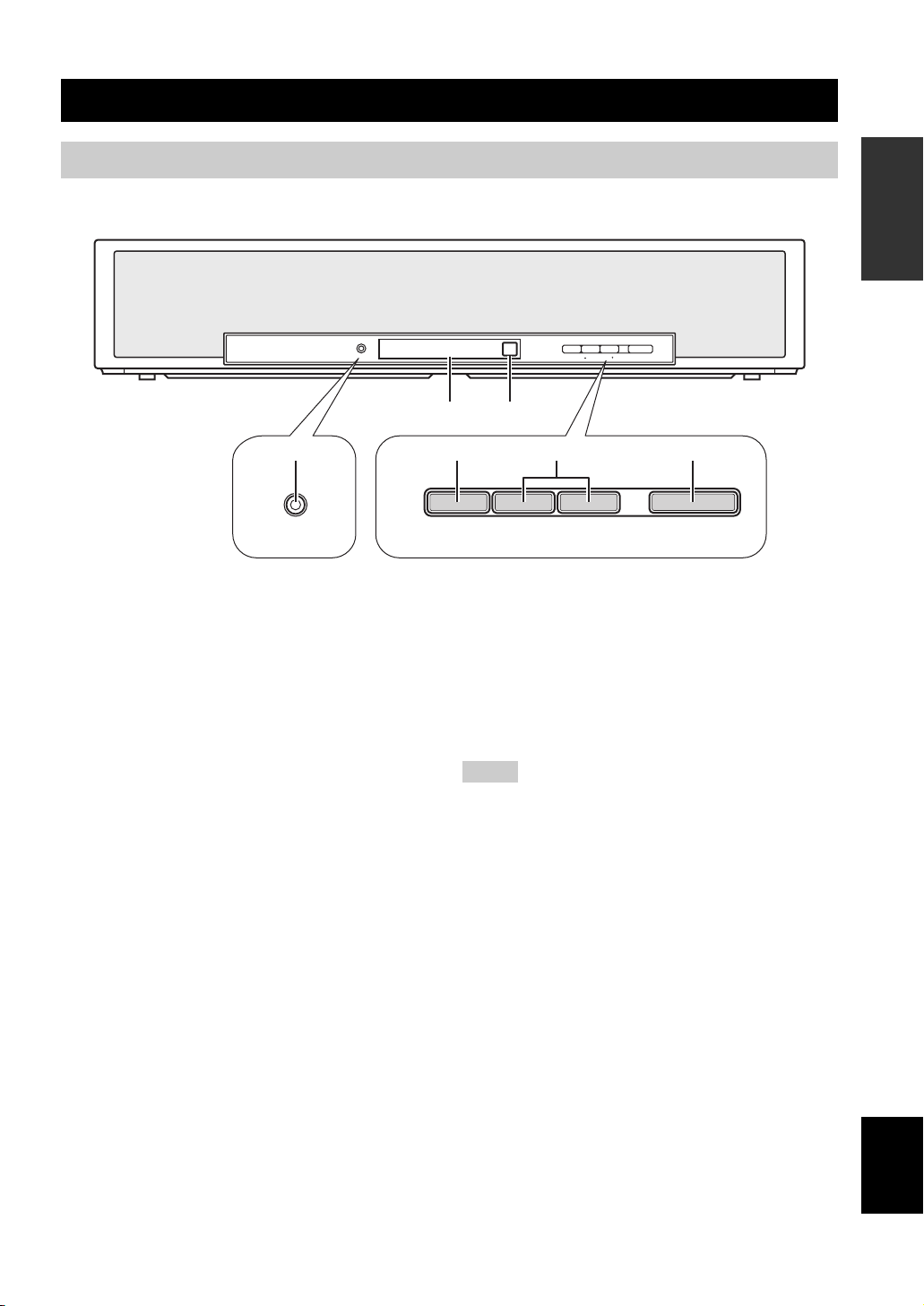
INTELLIBEAM MIC INPUT VOLUME STANDBY/ON
14
INTELLIBEAM MIC
1 INTELLIBEAM MIC jack
Connect the supplied IntelliBeam microphone for AUTO
SETUP (see page 33).
2 Front panel display
Shows information about the operational status of this
unit.
3 Remote control sensor
Receives infrared signals from the remote control.
4 INPUT
Press repeatedly to switch between input sources (see
page 42).
2
INPUT
3
5
– VOLUME +
6
STANDBY/ON
5 VOLUME +/–
Controls the volume level of all audio channels (see
page 44).
6 STANDBY/ON
Turns on the power of this unit or sets it to the standby
mode (see page 28).
Notes
• When you turn on this unit, you will hear a click sound
followed by the 4 to 5-second interval before sound
reproducing.
• In the standby mode, this unit consumes a small amount of
power in order to receive infrared signals from the remote
control or to search for HDMI signals.
7 En
English
Controls and functions
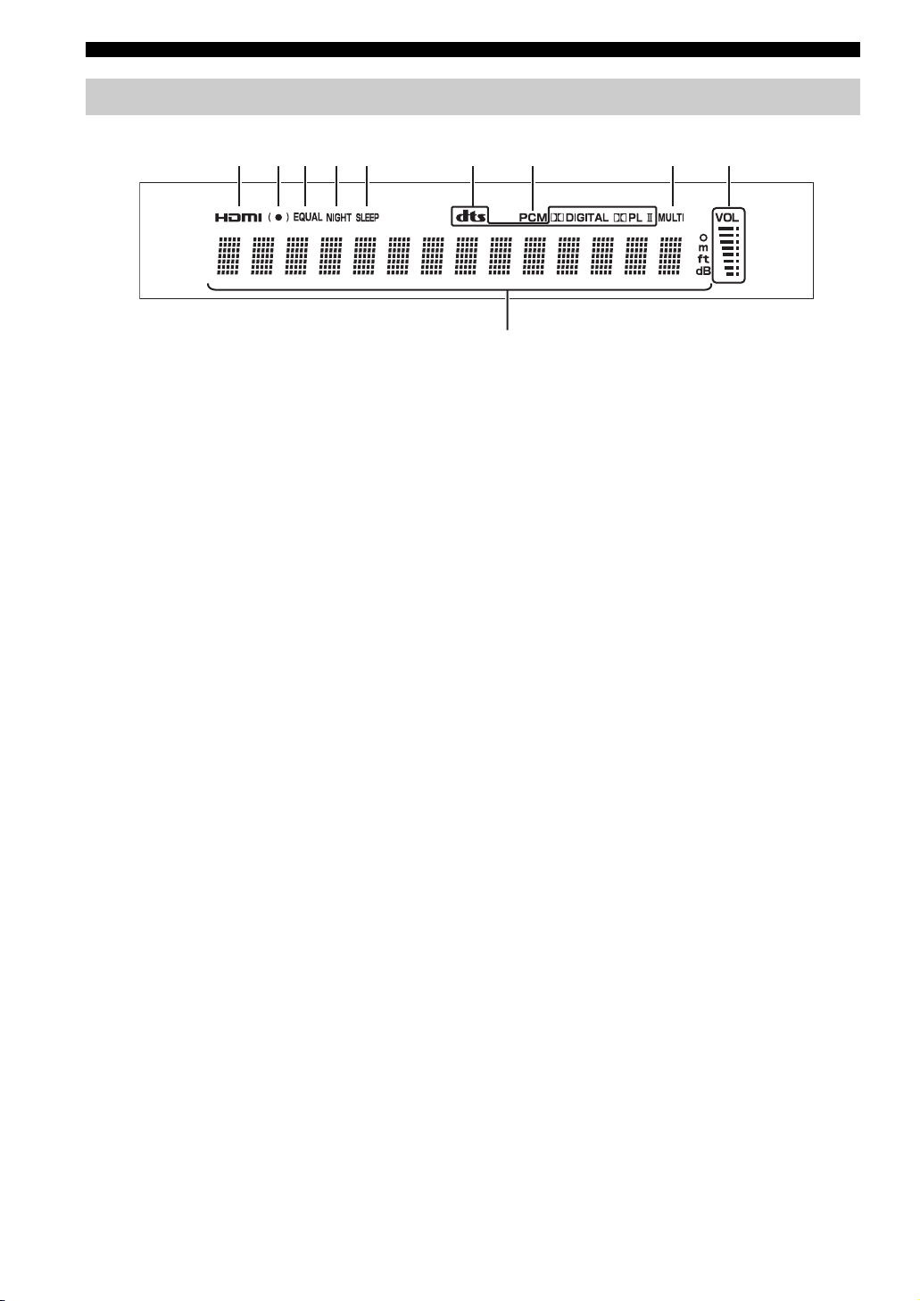
Front panel display
21 3 4 5
1 HDMI indicator
Lights up when the signal of the selected input source is
input at the HDMI IN jack(s).
2 SRS TruBass indicator
Lights up when TruBass is turned on (see page 65).
3 EQUAL indicator
Lights up when the TV volume equal mode is selected
(see page 54).
4 NIGHT indicator
Lights up when one of the night listening enhancers is
selected (see page 54).
5 SLEEP indicator
Lights up when the sleep timer is set (see page 55).
6 Decoder indicators
Light up when the corresponding decoder operates
(see page 47).
7 PCM indicator
Lights up when this unit is reproducing PCM (Pulse Code
Modulation) digital audio signals.
6
7 8
0
8 MULTI indicator
Lights up when this unit detects a multi channel digital
audio signal (see page 43).
9 Volume level indicator
Displays the current volume level.
0 Multi-information display
Shows information with alphanumeric characters when
you adjust the parameters of this unit.
y
You can adjust the brightness and display setting of the front
panel display using the F.DISPLAY SET parameter in MANUAL
SETUP (see page 69).
9
8 En
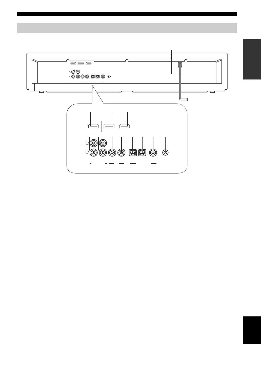
Rear panel
Controls and functions
INTRODUCTION
B
OUT DVD IN
L
R
VCR
AUX
HDMI
TV/STB VIDEO TV/STB AUX
SUBWOOFER
OPTICAL COAXIAL
DIGITAL INPUTOUTAUDIO INPUT
DVD SYSTEM
CONNECTOR
12
OUT DVD IN
7 8 9 0 A4 65
L
R
VCR TV/STB VIDEO TV/STB AUX
SUBWOOFER
1 HDMI OUT jack
Connect to the HDMI input jack on your HDMI
component such as a TV or a projector connected to this
unit (see page 18).
2 DVD HDMI IN jack
Connect your DVD player via an HDMI connection (see
page 18).
3 AUX HDMI IN jack
Connect your digital satellite tuner, cable TV tuner, digital
airwave tuner, or game console via an HDMI connection
(see page 18).
4 VCR AUDIO INPUT jacks
Connect your VCR via an analog connection (see
page 23).
5 TV/STB AUDIO INPUT jacks
Connect your TV, digital satellite tuner, or cable TV tuner
via an analog connection (see pages 19 and 21).
6 SUBWOOFER OUT jack
Connect your subwoofer (see page 25).
3
AUX
HDMI
DVD SYSTEM
OPTICAL COAXIAL
DIGITAL INPUTOUTAUDIO INPUT
CONNECTOR
7 VIDEO OUT jack
Connect to the video input jack of your TV to display the
OSD of this unit (see page 19).
8 TV/STB OPTICAL DIGITAL INPUT jack
Connect your TV, digital satellite tuner, or cable TV tuner
via an optical digital connection (see pages 19 and 21).
9 AUX OPTICAL DIGITAL INPUT jack
Connect an external component via an optical digital
connection (see page 24).
0 DVD COAXIAL DIGITAL INPUT jack
Connect your DVD player via a coaxial digital connection
(see page 20).
A SYSTEM CONNECTOR jack
Use to connect a Yamaha subwoofer equipped with a
SYSTEM CONNECTOR jack to this unit (see page 25).
B AC power supply cable
Connect to the AC wall outlet (see page 26).
9 En
English
Controls and functions
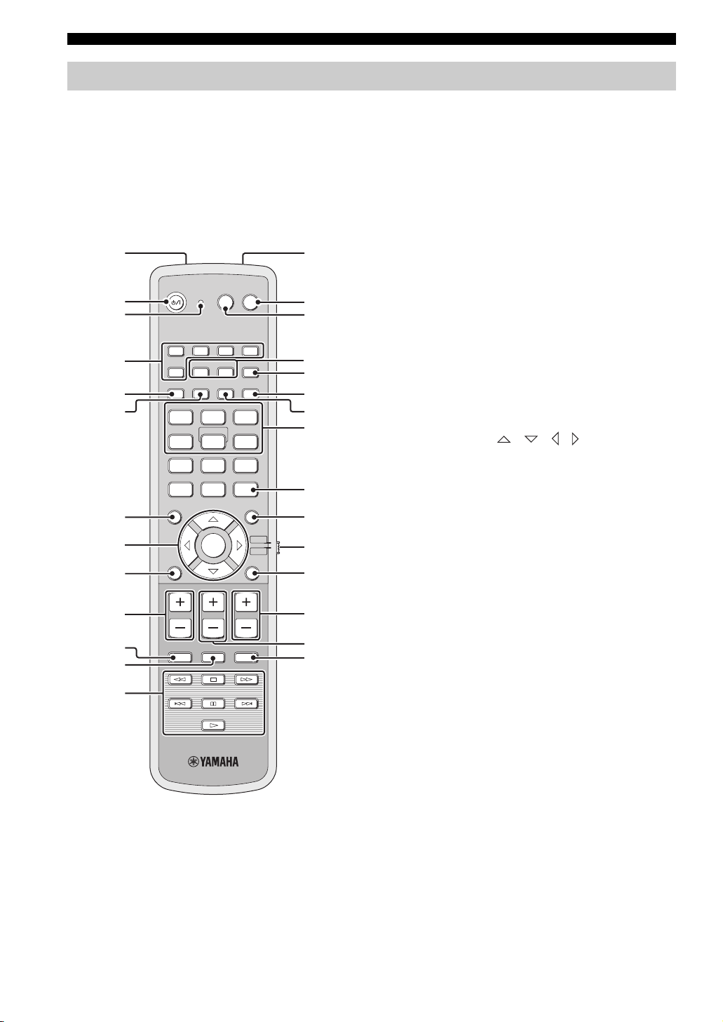
Remote control
This section describes the functions of the remote control
used to control this unit. Some buttons marked with an
asterisk (*) share the common functions between the YSP
and TV/AV operation modes (N).
y
You can also control other components using the remote control
once you set the appropriate remote control codes. See
“Controlling other components” on page 77 for details.
1D
POWERPOWERSTANDBY/ON
TV
INPUT2INPUT1
INPUTMODE
5
CH
TVAV
MACRO
SLEEP
321
MY SUR.
6
9
SUR. DECODE
TV/AV
RETURNTEST
TV VOL
CODE SET
YSP
E
F
G
H
I
J
K
L
M
N
O
P
Q
R
*
*
*
*
*
*
*
2
*
3
VCR DVD AUX
4
*
5
6
STB
TV
AUTO
SETUP
VOL MODE
5BEAM ST+3BEAM 3BEAM
STEREO
MY BEAM
4
78
+10
0
CH LEVEL MENU
7
8
ENTER
9
VOLUME
0
*
MUTE
A
*
B
*
C
*
TV INPUT TV MUTE
1 Infrared window
Outputs infrared control signals. Aim this window at the
component you want to operate.
2 STANDBY/ON
Turns on the power of this unit or sets it to the standby
mode (see page 28).
3 Transmission indicator
Lights up when infrared control signals are being output.
4 Input selector buttons
Use to select an input source (STB, VCR, DVD, AUX, or
TV).
5 VOL M ODE
Turns on or off the volume modes (see page 54).
6 AUTO SETUP
Enters the AUTO SETUP menu (see page 34).
7 CH LEVEL
Adjusts the volume level of each channel (see page 71).
8 Cursor buttons / / / , ENTER
Select and adjust SET MENU items.
9 TEST
Outputs a test tone when adjusting the output level of each
channel (see page 70).
0 VOLU ME +/–
Increases or decreases the volume level of this unit (see
page 44).
A MUTE
Mutes the sound. Press again to restore the audio output to
the previous volume level (see page 44).
B TV INPUT
Toggles between the input sources on the TV (see
page 77).
C DVD player/VCR control buttons
Control your DVD player or VCR (see pages 78 and 79).
D My Beam microphone
Collects the test tones from this unit when using the My
Beam auto-adjust function (see page 52).
E TV POWER
Turns on the power of your TV or sets it to the standby
mode (see page 77).
10 En
F AV P OWER
Turns on the power of the selected component or sets it to
the standby mode (see pages 78 and 79).
G INPUT1/INPUT2
Switches the input source on your TV (see page 77).

H MACRO
Use to set the TV macro (see page 80).
I SLEEP
Sets the sleep timer (see page 55).
J INPUTMODE
Toggles between input modes (AUTO, DTS, and
ANALOG) (see page 73).
K Beam mode buttons
Change the beam mode settings (see pages 45, 51, and
52).
L SUR. DECODE
Selects the surround mode for playback (see page 48).
M MENU
Displays the setup menu on your TV monitor (see
pages 34 and 59).
N Operation mode selector
Selects the operation mode of this unit. Select YSP when
operating this unit and select TV/AV when operating your
TV or other AV components.
O RETURN
Returns to the previous SET MENU screen.
P TV VOL +/–
Adjusts the volume level of your TV (see page 77).
Q CH +/–
Changes the channels of your TV, digital satellite tuner,
cable TV tuner, or VCR (see pages 77 to 80).
R TV MUTE, CODE SET
Mutes the audio output of your TV (see page 77).
Sets up remote control codes (see page 76).
Controls and functions
INTRODUCTION
11 En
English
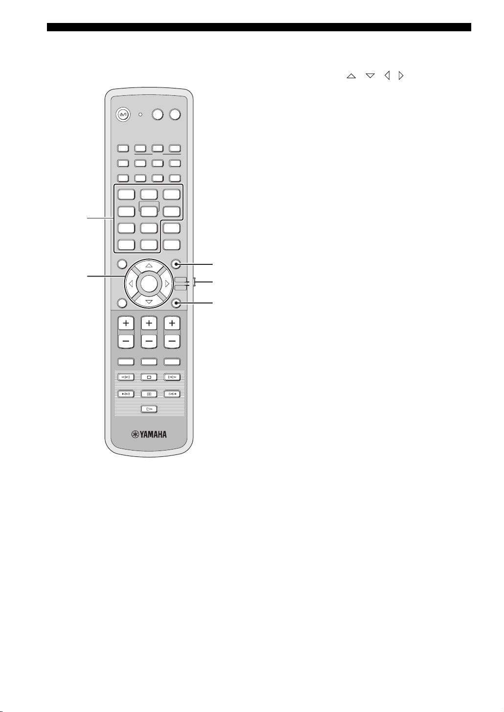
Controls and functions
This section describes the functions of the remote control
used to control other components when the TV/AV mode
is selected with the operation mode selector (4).
POWERPOWERSTANDBY/ON
TVAV
VCR DVD AUX
1
STB
TV
VOL MODE
5BEAM ST+3BEAM 3BEAM
STEREO
4
78
0
CH LEVEL MENU
AUTO
SETUP
INPUTMODE
MY BEAM
5
+10
TV
INPUT2INPUT1
MACRO
SLEEP
321
MY SUR.
6
9
SUR. DECODE
3
2
ENTER
TV/AV
YSP
RETURNTEST
4
5
VOLUME
TV VOL
CH
1 Numeric buttons
Enter numbers.
2 Cursor buttons / / / , ENTER
Use to select DVD menu items.
3 MENU
Displays the DVD menu.
4 Operation mode selector
Selects the operation mode of this unit. Select YSP when
operating this unit and select TV/AV when operating your
TV or other AV components.
5 RETURN
Use to return to the previous DVD menu screen or exit
from the DVD menu.
MUTE
TV INPUT TV MUTE
CODE SET
12 En
Installation
Installation
This section describes a suitable installation location to install this unit using a rack.
Depending on your installation environment, connections with external components can be done before installing this
unit. We recommend that you temporarily place and arrange all components, including this unit, in order to decide which
procedure should come first.
Before installing this unit
This unit creates surround sound by reflecting projected
sound beams off the walls of your listening room. The
surround sound effects produced by this unit may not be
sufficient when this unit is installed in the following
locations.
• Rooms with walls inadequate for reflecting sound
beams
• Rooms with acoustically absorbent walls
• Rooms with measurements outside the following
range: W (3 to 7 m (10 to 23 ft)) x H (2 to 3.5 m (7 to
11.5 ft)) x D (3 to 7 m (10 to 23 ft))
• Rooms with less than 1.8 m (6 ft) from the listening
position to this unit
• Rooms where objects such as furniture are likely to
obstruct the path of sound beams
• Rooms where the listening position is close to the walls
• Rooms where the listening position is not in front of
this unit
y
• You can enjoy surround sound by selecting My Surround (see
page 46) as the beam mode even if your listening room may not
fulfill the above conditions (except when the listening position
is not directly facing toward the front of this unit).
• You can also enjoy surround sound by selecting stereo playback
(see page 51) or My Beam (see page 52) as the beam mode even
if your listening room may not fulfill the above conditions.
Make sure you leave an adequate amount of ventilation
space so that heat can escape. Make at least 5 cm (2 in) of
space above this unit.
Notes
• We do not recommend putting this unit directly on the floor of
your listening room. Please install this unit using a rack.
• This unit weights 8.5 kg (18 lbs 12 oz). Be sure to install this
unit where it will not fall subject to vibrations, such as from an
earthquake, and where it is out of the reach of children.
• When using a cathode-ray tube (CRT) TV, do not install this
unit directly above your TV.
• This unit is shielded against magnetic rays. However, if the
picture on your TV screen becomes blurred or distorted, we
recommend moving this unit away from your TV.
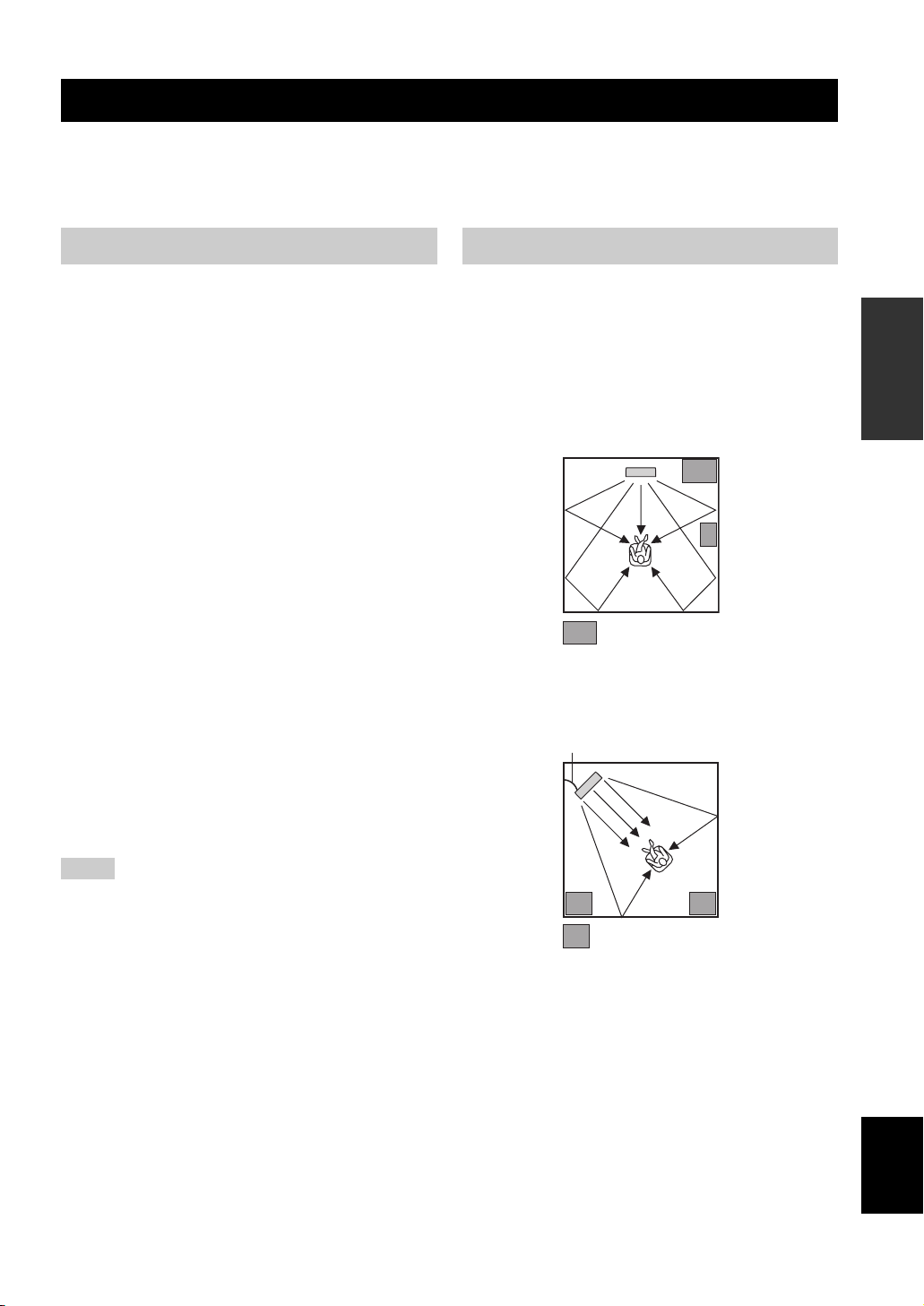
Installing this unit
Install this unit where there are no obstacles such as
furniture obstructing the path of sound beams. Otherwise,
the desired surround sound effects may not be achieved.
You may install this unit in parallel with the wall or in the
corner.
Parallel installation
Install this unit in the exact center of the wall when it is
measured from the left and right corners.
An object, such as furniture
Corner installation
Install this unit in the corner at a 40º to 50º angle from the
adjacent walls.
40° to 50°
An object, such as furniture
PREPARATION
13 En
English
Installation
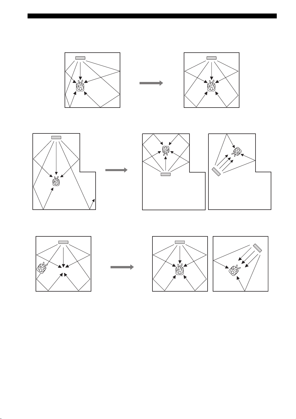
■ Installation examples
Example 1
Install this unit as close to the exact center of the wall as possible.
Example 2
Install this unit so that the sound beams can be reflected off the walls.
Example 3
Install this unit as close to the exact front of your normal listening position as possible.
14 En

■ Using a rack
Install this unit under your TV in a commercially available
rack.
Installation
This unit
Note
Make sure that the rack is large enough to allow adequate
ventilation space around this unit (see page 13) and that it is
strong enough to support the weight of both this unit and your TV.
PREPARATION
15 En
English
Connections
Connections
This unit is equipped with the following types of audio/video input/output jacks/terminal:
For audio input
• 2 optical digital input jacks
• 1 coaxial digital input jack
• 2 sets of analog input jacks
For audio/video input
• 2 HDMI input jacks
Use these jacks/terminal to connect external components such as your TV, DVD player, VCR, digital satellite tuner, cable
TV tuner, digital air wave tuner, and game console. Further, by connecting a subwoofer to this unit, you can enjoy
reinforced low-bass sounds. For details on how to connect various types of external components to this unit, see pages 18
to 26.
CAUTION
• Do not connect this unit or other components to the mains power until all connections between components are
complete.
• Unplug the AC power supply cable before changing connections, moving or cleaning this unit.
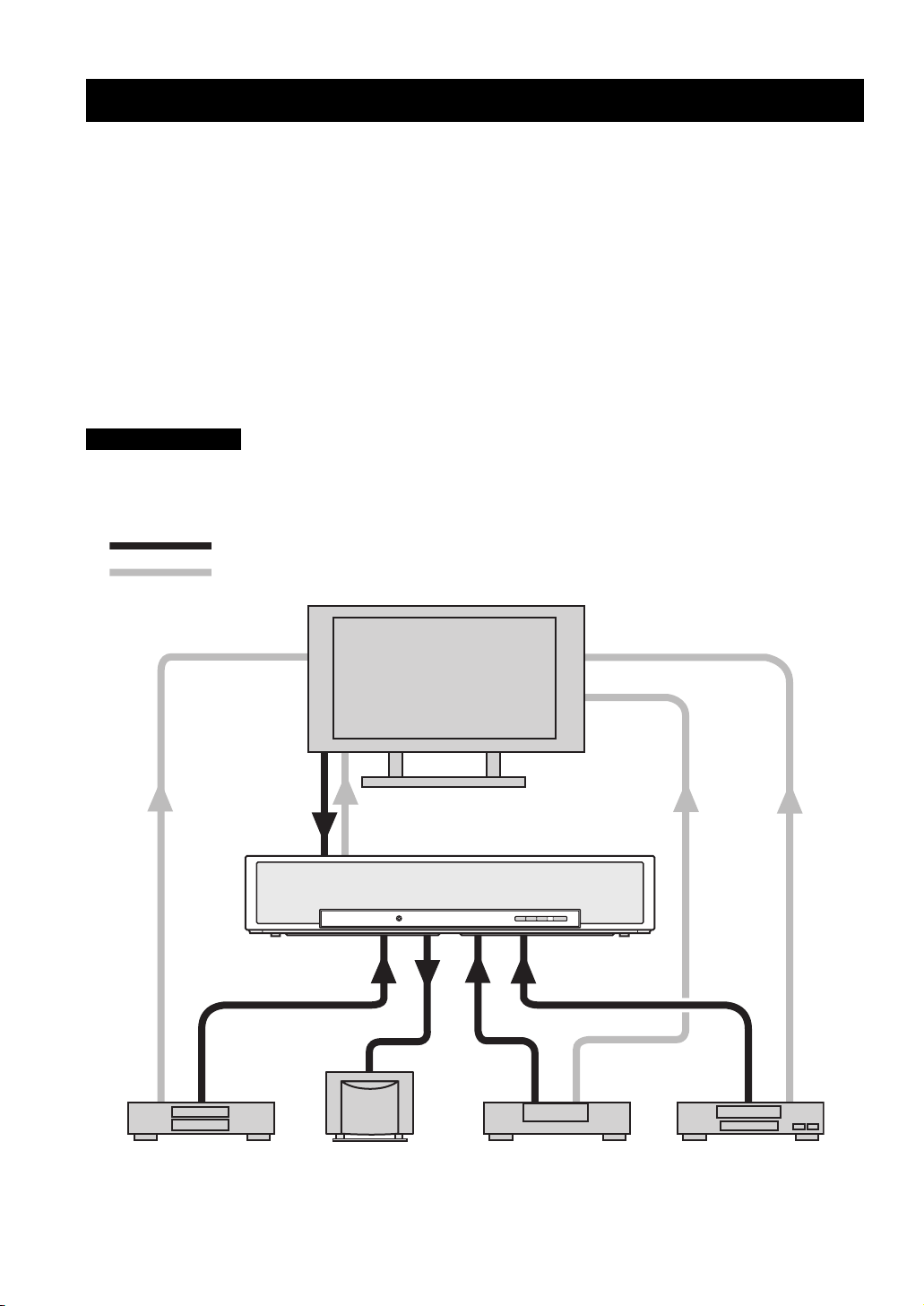
Audio connection
Video connection
TV
For audio output
• 1 subwoofer output jack
For audio/video output
• 1 HDMI output jack
For video output
• 1 analog output jack
16 En
This unit
VCR or game consoleDVD player Subwoofer Digital satellite tuner
or cable TV tuner
Before connecting components
Connections
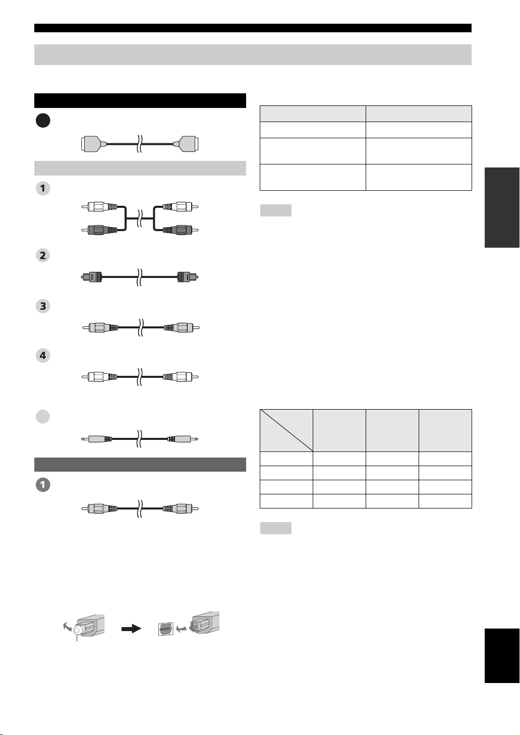
■ Cables used for connections
Audio/Video
HDMI cable
A
Audio
Audio pin cable (supplied)
(White)
(Red)
Optical cable (supplied)
Digital audio pin cable (supplied)
Subwoofer pin cable
System connector cable
5
Video
OSD video pin cable (supplied)
(White)
(Red)
(Orange)(Orange)
(Yellow)(Yellow)
■ Information on HDMI™
Audio signals
Input source Audio signal type
DVD video Dolby Digital, DTS, PCM
DVD audio
Blu-ray Disc
HD DVD
2-channel stereo
(up to 96 kHz/24 bit)
Dolby Digital, DTS, PCM
Notes
•
When CPPM copy-protected DVD audio is played back, video and
audio signals may not be output depending on the type of DVD player.
• This unit is not compatible with HDCP-incompatible HDMI or
DVI components.
y
• We recommend that you use an HDMI cable shorter than 5 m
(16 ft) with the HDMI logo printed on it.
• Use a conversion cable (HDMI jack
this unit to other DVI components.
↔ DVI-D jack) to connect
■ Priority order for audio input signals
When multiple types of audio signals are simultaneously
being input from a single source component, this unit
plays back the audio signals in the following priority
order: HDMI → Digital → Analog
As default settings, the following input jacks are assigned
to the corresponding input sources:
Input
jack
Input
source
TV/STB ✔✔
DVD ✔✔
AUX ✔✔
VCR ✔
HDMI Digital Analog
PREPARATION
■ Notes on connecting the optical cable
• Pull out the cap before connecting the optical cable.
When you are not using the optical cable, be sure to put
the cap back in place.
• When inserting the cable into the optical digital jack,
make sure the direction is correct.
Cap
Note
This unit is compatible with 2-channel PCM signals, but not with
multi-channel PCM signals.
English
17 En
Connections
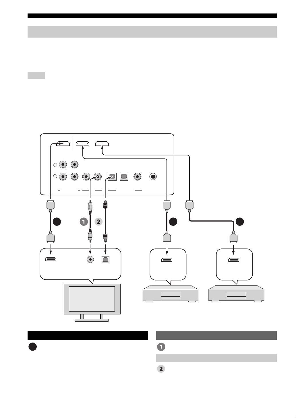
Connections using HDMI cables
This unit is equipped with 2 HDMI input jacks and 1 HDMI output jack. If your TV and other components have HDMI
jacks, use HDMI cables for simpler and easier connections, and you can skip the connection procedures from page 19 to
21. If your TV has a built-in digital satellite tuner and an optical digital output jack, connect the optical digital output jack
on your TV to the TV/STB OPTICAL DIGITAL IN jack on this unit.
Notes
• Even if you connect your TV and this unit via the HDMI jack, you need to connect the video input jack on your TV to the VIDEO
OUT jack on this unit in order to display the OSD of this unit.
• When HDMI CONTROL is set to OFF (see page 68) and this unit is in the standby mode, the signals input at the HDMI IN jacks are
not output at the HDMI OUT jack.
y
We recommend that you secure the HDMI cable(s) with adhesive tape, etc. once you have connected the HDMI cable(s) to the HDMI
jack(s) of this unit.
Rear panel of this unit
AUXDVD INOUT
HDMI
*
This connection (except
L
R
VCR TV/STB VIDEO TV/STB AUX
SUBWOOFER
OPTICAL COAXIAL
DIGITAL INPUTOUTAUDIO INPUT
DVD SYSTEM
CONNECTOR
for a game console) is not
necessary if your TV has a
built-in digital satellite
tuner, cable TV tuner, or
digital airwave tuner.
HDMI
input
Video
input
Optical
digital
output
HDMI
output
DVD player/recorder
TV
Audio/Video
HDMI cable OSD video pin cable
A
Optical cable
AAA
HDMI
output
Digital satellite tuner,
cable TV tuner,
digital airwave tuner,
or game console
Video
Audio
18 En
Connections
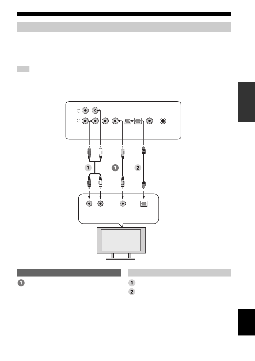
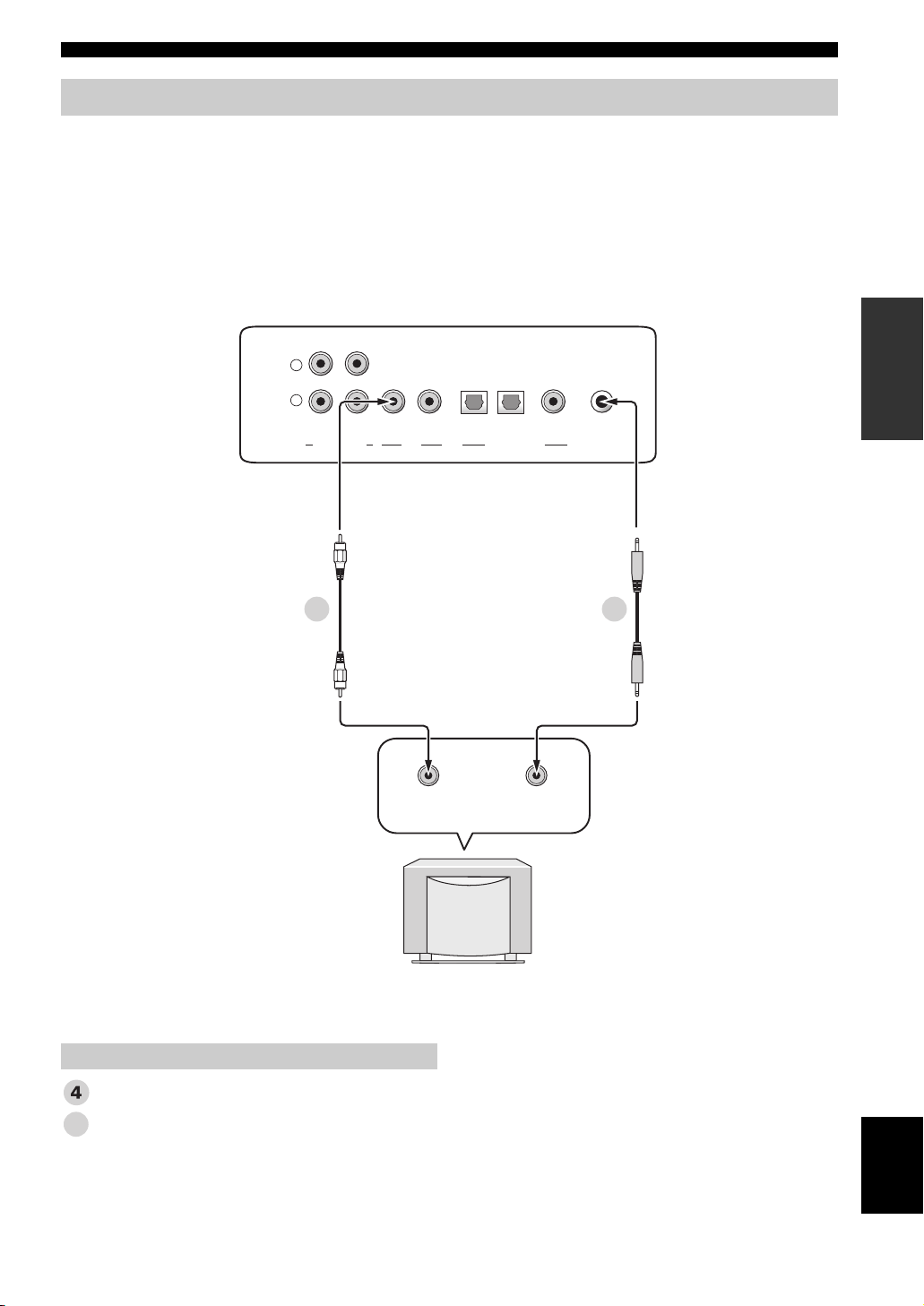
Connecting a TV
For audio connection, connect the analog audio output jacks on your TV to the TV/STB AUDIO INPUT jacks on this
unit. If your TV has an optical digital output jack, connect the optical digital output jack on your TV to the TV/STB
OPTICAL DIGITAL INPUT jack on this unit.
For video connection, connect the video input jack on your TV to the VIDEO OUT jack on this unit to display the OSD
for easy viewing when you adjust the system parameters in SET MENU.
Note
If you make analog and optical digital audio connections at the same time as shown in the illustration below, the digital audio signals
input at the TV/STB OPTICAL DIGITAL INPUT jack take priority over the analog audio signals input at the TV/STB AUDIO INPUT
jacks.
Rear panel of this unit
L
R
VCR TV/STB VIDEO TV/STB AUX
SUBWOOFER
OPTICAL COAXIAL
DIGITAL INPUTOUTAUDIO INPUT
DVD SYSTEM
CONNECTOR
PREPARATION
RL
Analog
audio
output
Video
input
Optical
digital
output
TV
Video Audio
OSD video pin cable Audio pin cable
Optical cable
English
19 En
Connections
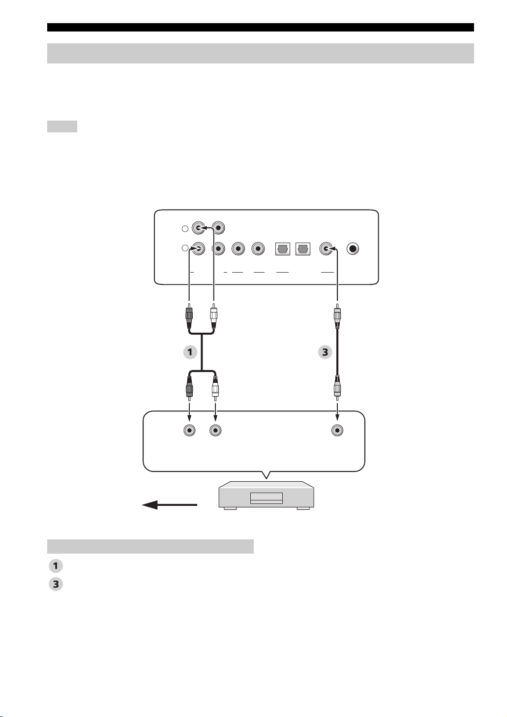
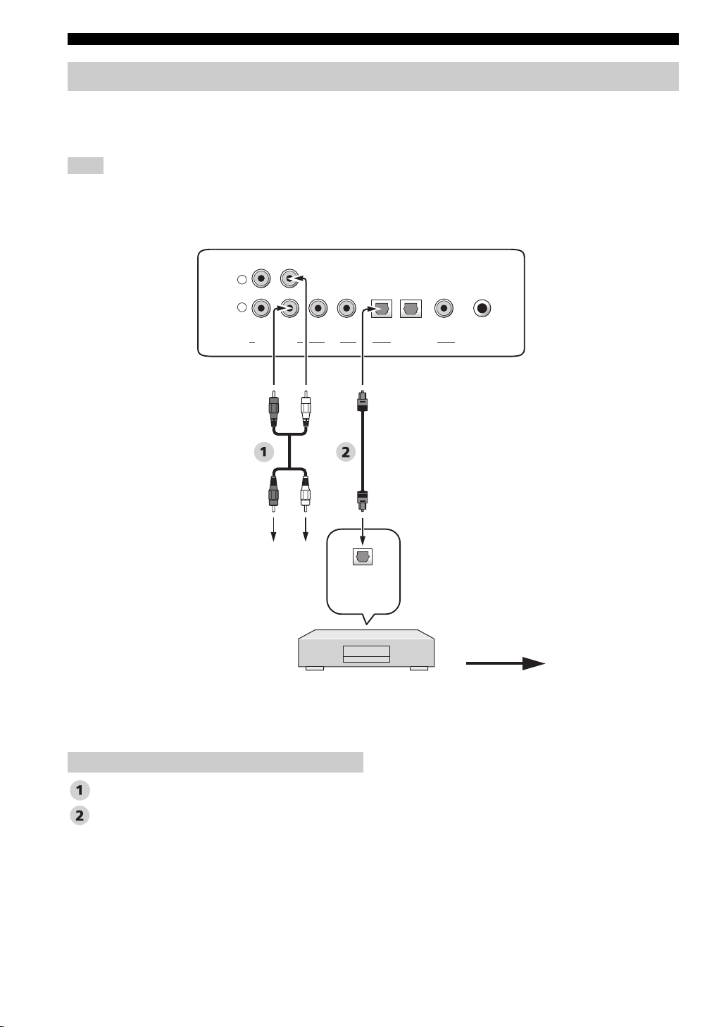
Connecting a DVD player/recorder
Connect the coaxial digital output jack on your DVD player/recorder to the DVD COAXIAL DIGITAL INPUT jack on
this unit. When you connect this unit to your DVD/VCR combo player/recorder, connect the analog audio output jacks on
your DVD/VCR combo player/recorder to the VCR AUDIO INPUT jacks on this unit in addition to the coaxial digital
audio connection.
Notes
• Check that your DVD player/recorder is properly set to output Dolby Digital and DTS digital audio signals. If not, adjust the system
settings of your DVD player/recorder. For details, refer to the operation manual supplied with your DVD player/recorder.
• If your DVD player/recorder does not have a coaxial digital output jack, make an optical digital audio connection instead (see
page 24).
Rear panel of this unit
L
R
VCR TV/STB VIDEO TV/STB AUX
SUBWOOFER
OPTICAL COAXIAL
DIGITAL INPUTOUTAUDIO INPUT
DVD SYSTEM
CONNECTOR
Video signal to the TV
Audio
Audio pin cable
Digital audio pin cable
*
For the DVD/VCR combo
player/recorder
connection
LR
Analog
audio
output
DVD player/recorder
Coaxial
digital
output
20 En
Connections
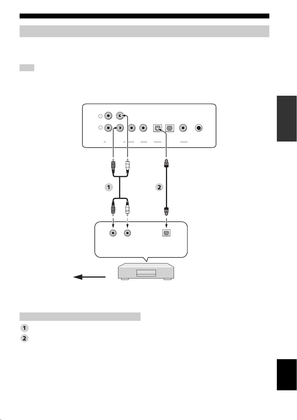
Connecting a digital satellite tuner or a cable TV tuner
Connect the optical digital output jack on your digital satellite tuner or cable TV tuner to the TV/STB OPTICAL
DIGITAL INPUT jack on this unit. Connect the analog audio output jacks on your digital satellite tuner or cable TV
tuner to the TV/STB AUDIO INPUT jacks on this unit.
Note
This connection is not necessary if your TV has a built-in digital satellite tuner or cable TV tuner (see “Connecting a TV” on page 19).
L
R
VCR TV/STB VIDEO TV/STB AUX
SUBWOOFER
LR
Analog
audio
output
Rear panel of this unit
OPTICAL COAXIAL
DIGITAL INPUTOUTAUDIO INPUT
Optical
digital
output
DVD SYSTEM
PREPARATION
CONNECTOR
Video signal to the TV
Audio pin cable
Optical cable
Digital satellite tuner
or cable TV tuner
Audio
English
21 En
Connections
Connecting a digital airwave tuner
Connect the TV/STB AUDIO INPUT jacks on this unit to the analog audio output jacks on your TV. Connect the optical
digital output jack on your digital airwave tuner to the TV/STB OPTICAL DIGITAL INPUT jack on this unit in addition
to the analog audio connection. By doing so, you can enjoy both analog and digital broadcasts.
Note
This connection is not necessary if your TV has a built-in digital airwave tuner (see “Connecting a TV” on page 19).
Rear panel of this unit
R
VCRLTV/STB VIDEO
SUBWOOFER
OUTAUDIO INPUT
TV/STB AUX
OPTICAL COAXIAL
DIGITAL INPUT
DVD SYSTEM
CONNECTOR
Audio pin cable
Optical cable
Connect to the analog
audio output jacks on
the TV.
Audio
Optical
digital
output
Digital airwave tuner
Video signal to the TV
22 En
Connections
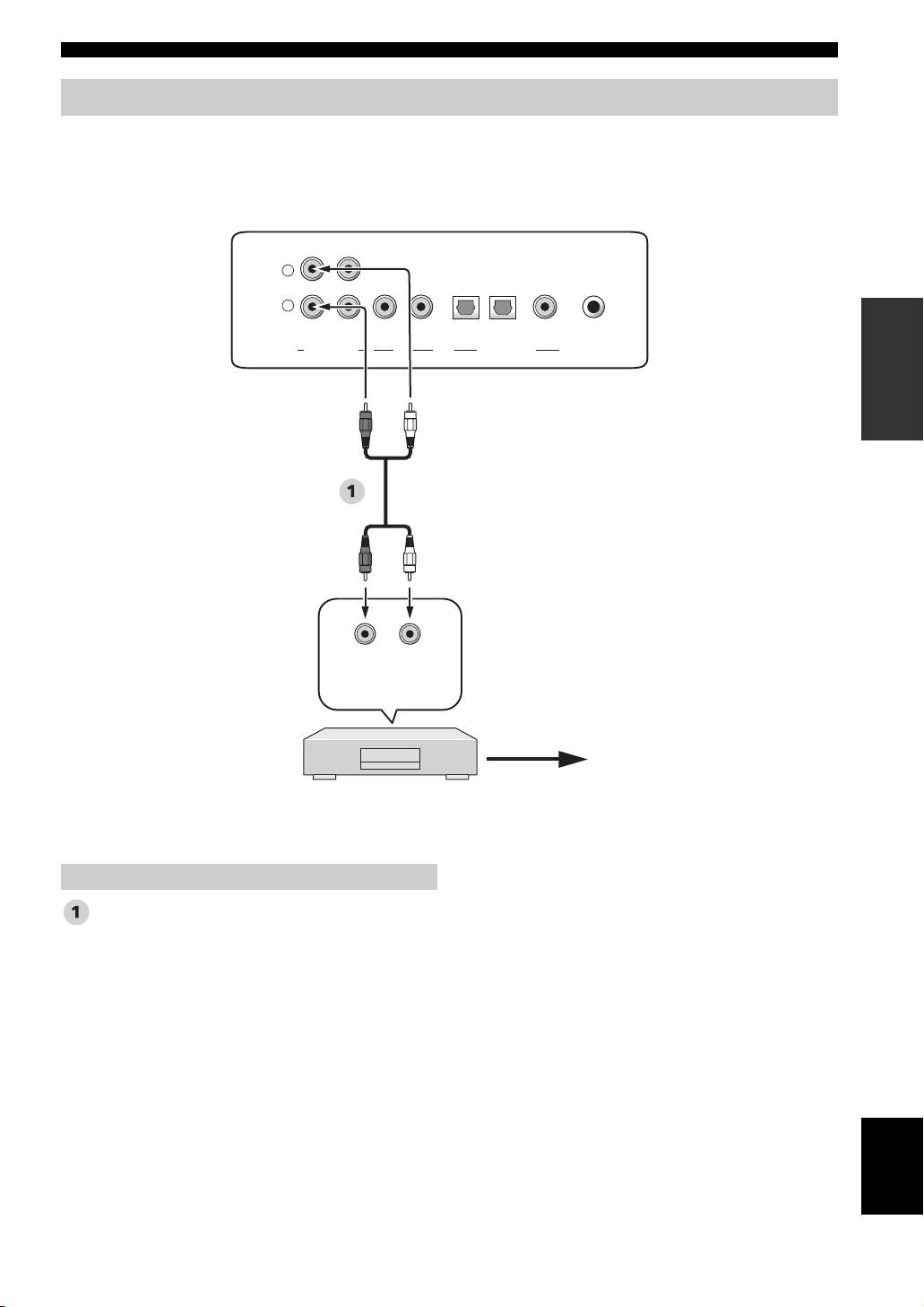
Connecting a VCR
To connect a VCR, connect the analog audio output jacks on your VCR to the VCR AUDIO INPUT jacks on this unit.
Connect red plugs to the right jacks and white plugs to the left jacks.
Rear panel of this unit
L
R
VCR TV/STB VIDEO TV/STB AUX
SUBWOOFER
LR
Analog
audio
output
VCR
DVD SYSTEM
OPTICAL COAXIAL
DIGITAL INPUTOUTAUDIO INPUT
CONNECTOR
Video signal to the TV
PREPARATION
Audio pin cable
Audio
English
23 En
Connections
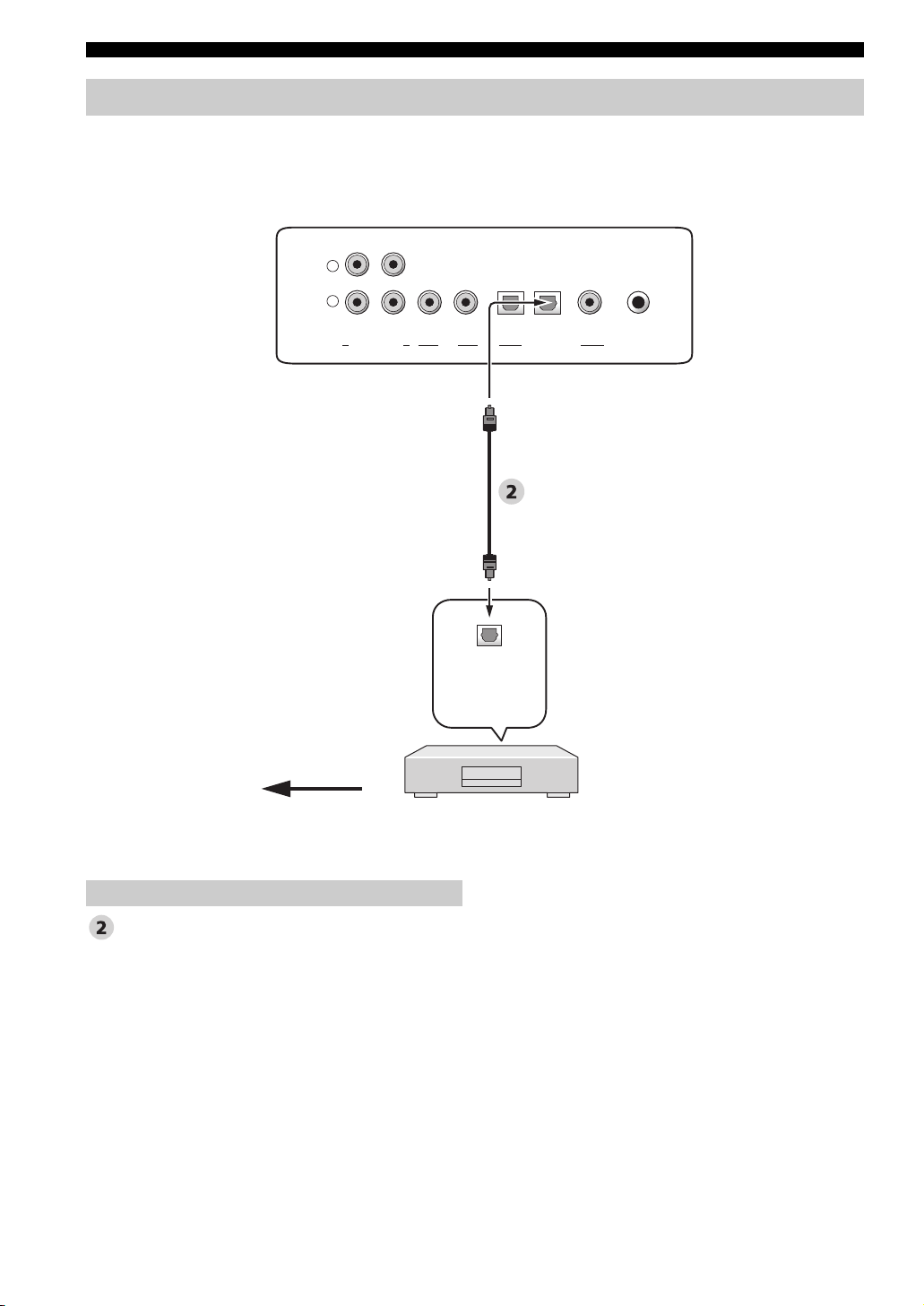
Connecting other external components
If your component supports optical digital connections, connect the optical digital output jack on your component
(e.g., DVD player/recorder) to the AUX OPTICAL DIGITAL INPUT jack on this unit.
Rear panel of this unit
L
R
VCR TV/STB VIDEO TV/STB AUX
SUBWOOFER
OPTICAL COAXIAL
DIGITAL INPUTOUTAUDIO INPUT
DVD SYSTEM
CONNECTOR
Optical cable
Video signal to the TV
Audio
Optical
digital
output
DVD player/recorder,
game console, CD player, etc.
24 En
Connections
Connecting a subwoofer
Connect the monaural input jack on your subwoofer to the SUBWOOFER jack on this unit.
This connection alone does not output sound from the connected subwoofer. To output sound from the connected
subwoofer, turn on the power of your subwoofer and then run AUTO SETUP (see page 32) or select SWFR for BASS
OUT in SUBWOOFER SET (see page 64).
When connecting a Yamaha subwoofer equipped with a SYSTEM CONNECTOR terminal, connect it to the SYSTEM
CONNECTOR terminal on this unit. If the subwoofer is connected using a system type connection, changing the power
mode of this unit controls the power mode of the subwoofer.
Rear panel of this unit
L
R
VCR TV/STB VIDEO TV/STB AUX
SUBWOOFER
OPTICAL COAXIAL
DIGITAL INPUTOUTAUDIO INPUT
DVD SYSTEM
4 5
Monaural
input
SYSTEM
CONNECTOR
PREPARATION
CONNECTOR
Subwoofer pin cable
System connector cable
5
Subwoofer
Audio
English
25 En
Connections
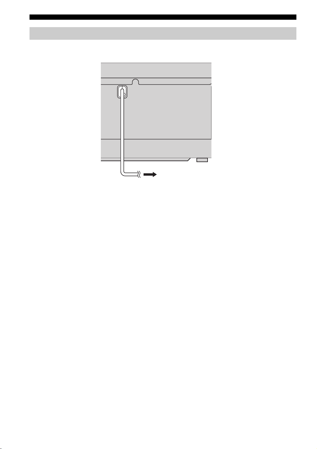
Connecting the AC power supply cable
Once all other connections are complete, plug the AC power supply cable into the AC wall outlet.
To the AC wall outlet
26 En
Getting started
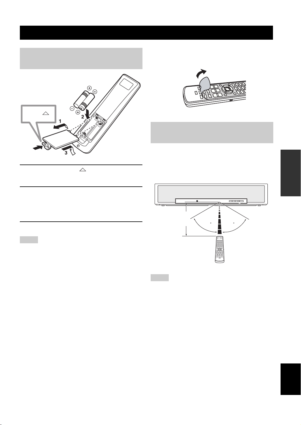
Installing batteries in the remote
control
Press
1 Press and hold the mark on the battery
cover and then open the cover.
GETTING STARTED
y
Remove the transparent sheet before using the remote control.
Operation range of the remote
control
The remote control transmits a directional infrared beam.
Use the remote control within 6 m (20 ft) of this unit and
point it toward the remote control sensor of this unit
during operation.
SETUP
2 Insert the two supplied batteries (AA, R6,
UM-3) into the battery compartment.
Make sure you insert the batteries according to the
polarity markings (+/–).
3 Close the battery cover.
Notes
• Change all of the batteries if you notice the following
conditions: the operation range of the remote control decreases
or the transmission indicator does not light up or becomes dim.
• Do not use old batteries together with new ones.
• Do not use different types of batteries (such as alkaline and
manganese batteries) together. Read the packaging carefully as
these different types of batteries may have the same shape and
color.
• Exhausted batteries may leak. If the batteries have leaked,
dispose of them immediately. Avoid touching the leaked
material or letting it come into contact with clothing, etc. Clean
the battery compartment thoroughly before installing new
batteries.
• Do not throw away batteries with general house waste. Dispose
of them correctly in accordance with your local regulations.
• The memory stored in the remote control may be erased in the
following cases:
– The remote control is left without batteries for more than two
minutes.
– Exhausted batteries remain in the remote control.
– The buttons on the remote control are accidentally pressed
when you change batteries.
• If the memory stored in the remote control is unwantedly
erased, insert new batteries and set the remote control codes
again.
Approximately
6 m (20 ft)
30 30
Notes
• Do not spill water or other liquids on the remote control.
• Do not drop the remote control.
• Do not leave or store the remote control in the following places:
– places of high humidity, such as near a bath
– places of high temperatures, such as near a heater or a stove
– places of extremely low temperatures
– dusty places
• Do not expose the remote control sensor of this unit to direct
sunlight or lighting such as inverted fluorescent lamps.
• If the batteries grow old, the effective operation range of the
remote control decreases considerably. If this happens, replace
the batteries with two new ones as soon as possible.
English
27 En
Getting started
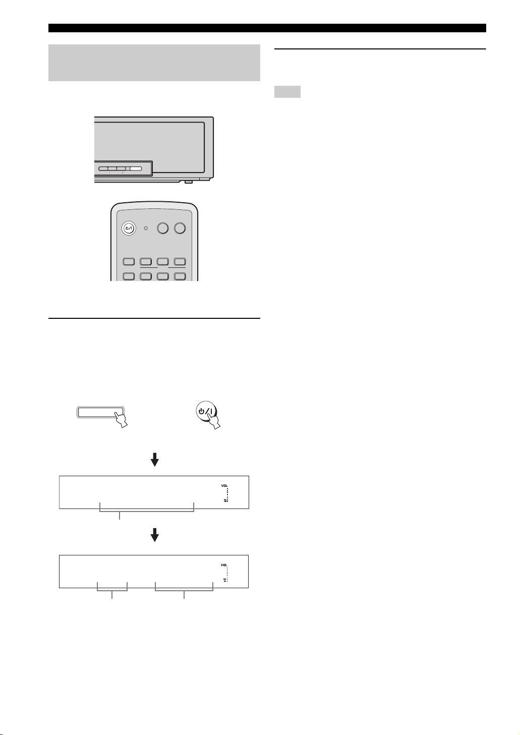
Turning on this unit or
setting it to the standby mode
INPUT VOLUME STANDBY/ON
POWERPOWERSTANDBY/ON
TVAV
VCR DVD AUX
STB
TV
1 Press STANDBY/ON to turn on the power of
this unit.
The volume level appears in the front panel display,
and the current input source and beam mode are
displayed.
TV
MACRO
INPUT2INPUT1
2 Press STANDBY/ON again to set this unit to
the standby mode.
Note
When this unit is in the standby mode, only STANDBY/ON on
the front panel or on the remote control is operational, and the
other control buttons on the front panel or on the remote control
are not operational until the power of this unit is turned on.
STANDBY/ON
Front panel
or
XXVOLUMEXX30XX
Current volume level
XXDVDXXXMYX SUR
Current input
source
Current beam
mode
STANDBY/ON
Remote control
28 En
 Loading...