

Page 1

Digital Sound Projector
Owner’s Manual
TM
English
for North America
Page 2
The “ ” logo and “IntelliBeam” are trademarks of Yamaha
Corporation.
The “ ” logo and “Cinema DSP” are registered trademarks of
Yamaha Corporation.
The “ ” and “UniVolume” are trademarks of Yamaha Corporation.
Manufactured under license from Cambridge Mechatronics Ltd. Worldwide
patents applied for.
The “ ” logo and “Digital Sound Projector
Cambridge Mechatronics Ltd.
“HDMI”, the “HDMI” logo and “High-Definition Multimedia Interface” are
trademarks or registered trademarks of HDMI Licensing LLC.
™
” are trademarks of
x.v.Color
“x.v.Color” is a trademark.
The “ ” and “yAired” are trademarks of Yamaha Corporation.
Manufactured under license from Dolby Laboratories.
Dolby, Pro Logic and the double-D symbol are trademarks of Dolby
Laboratories
Manufactured under license under U.S. Patent No’s:
5,451,942;5,956,674;5,974,380;5,978,762;6,226,616;6,487,535 & other U.S. and
worldwide patents issued & pending. DTS is a registered trademark and the DTS
logos, Symbol, DTS-HD and DTS-HD Master Audio are trademark of DTS, Inc. ©
1996-2007 DTS, Inc. All Rights Reserved.
iPod™, iPhone™
iPod is a trademark of Apple Inc., registered in the U.S. and other countries.
iPhone is a trademark of Apple Inc.
“Made for iPod” means that an electronic accessory has been designed to
connect specifically to iPod and has been certified by the developer to meet
Apple performance standards.
“Works with iPhone” means that an electronic accessory has been designed to
connect specifically to iPhone and has been certified by the developer to meet
Apple performance standards.
Apple is not responsible for the operation of this device or its compliance with
safety and regulatory standards.
SIRIUS, XM and all related marks and logos are trademarks of Sirius XM
Radio Inc. and its subsidiaries. All rights reserved. Service not available in
Alaska and Hawaii.
2 En
About this manual
• Make sure you read precautions in “Safety and Accessory Information” (separate booklet) carefully before using this unit.
• This manual describes how to connect and operate this unit. For details regarding the operation of external components, refer to the
supplied owner's manual for each component.
• Operations in this manual use keys on the supplied remote control of this unit unless otherwise specified.
• y indicates a tip for your operation.
• An illustration of the remote control in the left pages of this manual indicates the keys to be used in two facing (left and right) pages.
• This manual is produced prior to production. Designs and specifications are subject to change in part as a result of improvements,
etc. In case of differences between the manual and the product, the product has priority.
Page 3

CONTENTS
INTRODUCTION
Features........................................................................... 4
General operation flow .................................................. 5
Controls and functions................................................... 6
Front panel .........................................................................6
Front panel display............................................................. 7
Rear panel........................................................................... 8
Remote control ...................................................................9
PREPARATION
Installation .................................................................... 10
Connections................................................................... 12
Before connecting components........................................ 12
Connecting external components .....................................12
Connecting a subwoofer...................................................13
Connecting the FM antenna .............................................14
Preparing the remote control...................................... 14
Installing batteries in the remote control..........................14
Operation range of the remote control .............................14
Changing OSD language.............................................. 15
AUTO SETUP (IntelliBeam)....................................... 15
Installing the IntelliBeam microphone............................. 15
Using AUTO SETUP (IntelliBeam) ................................16
Using the system memory............................................ 19
Saving settings .................................................................19
Loading settings ............................................................... 19
Useful features .............................................................. 31
Adjusting volume level automatically (UniVolume).......31
Using the HDMI™ control function................................ 31
Using the sleep timer ....................................................... 31
Configuring settings for each input source
(Option menu).............................................................. 32
Displaying the input signal information .......................... 32
SETTINGS
Customizing this unit (SET MENU)........................... 33
SET MENU items............................................................ 33
Basic SET MENU operation............................................ 34
MANUAL SETUP........................................................... 34
SOUND SET MENU....................................................... 36
SOUND OUT MENU...................................................... 37
INPUT MENU................................................................. 38
DISPLAY MENU............................................................ 39
System configurations (ADVANCED SETUP) ......... 40
Using an external amplifier......................................... 41
Controlling external components ............................... 42
APPENDIX
Troubleshooting ........................................................... 43
Glossary......................................................................... 47
Specifications ................................................................ 48
List of remote control codes ........................................ 49
Index.............................................................................. 56
PREPARATIONINTRODUCTION APPENDIXPLAYBACK FEATURES SETTINGS
PLAYBACK FEATURES
Playback ........................................................................ 21
Playing back sources ........................................................ 21
Playing back TV sounds...................................................21
Playing back a player .......................................................21
Muting audio output.........................................................21
Decoder and input channel indicators.............................. 21
Playback mode.............................................................. 22
Selecting surround or stereo playback .............................22
Enjoying CINEMA DSP programs.................................. 22
Changing the audio output method for surround
playback........................................................................ 23
Enjoying 2-channel sources
in surround sound.........................................................24
Playing back 5.1-channel sources in
7.1-channel surround.................................................... 24
FM tuning ..................................................................... 25
Tuning into the desired FM station
(Frequency tuning) .......................................................25
Registering FM stations and tuning in (Preset tuning).....25
SIRIUS Satellite Radio™ tuning ................................ 26
Listening to Satellite Radio..............................................26
Connecting the SiriusConnect™ tuner.............................26
Activating SIRIUS Satellite Radio™ subscription ..........27
SIRIUS Satellite Radio™ operations..............................27
Registering SIRIUS Satellite Radio™ channels..............28
Setting the Parental Lock .................................................29
Displaying the SIRIUS Satellite Radio™ information....30
Playing back iPod™/iPhone™ .................................... 30
3 En
Page 4

INTRODUCTION
Features
Digital Sound Projector
The Digital Sound Projector technology allows one slim unit to
control and steer multiple channels of sound to generate multichannel surround sound, thus eliminates the need for satellite
loudspeakers and cabling normally associated with conventional
surround sound systems. This unit also employs the beam modes that
let you enjoy the surround sound (5 Beam, Stereo+3 Beam, 3 Beam
for 5.1-channel audio, 5 Beam plus 2, Stereo + 3 Beam plus 2, 3
Beam for 7.1-channel audio) and 2-channel stereo playback.
HDMI (High-Definition Multimedia Interface)
◆ HDMI input x 4, HDMI output x 1
◆ HDMI interface for standard, enhanced, or high-definition video
(including 1080p video signal transmission) as well as multi-channel
digital audio based on HDCP
– Automatic audio and video synchronization (lip sync) information
capability
– Deep Color video signal transmission capability
– “x.v.Color” video signal transmission capability
– High definition digital audio format signals capability
– Multi-channel Linear PCM signal capability
◆ Simple and easy connections with HDMI supported external components
◆ Functional link which enables the remote control of your TV to control
this unit (with an HDMI control-compatible TV)
– Power mode switch capability (on/standby)
– Volume adjustment capability
– TV sounds reproduce device selection capability (this unit/TV)
AUTO SETUP (IntelliBeam)
This unit employs the automatic sound beam and acoustic
optimization technology with the aid of the supplied IntelliBeam
microphone. You can avoid troublesome listening-based speaker
setup and achieve highly accurate sound beam adjustments that best
match your listening environment.
Wireless connection (yAired)
◆ Wireless connection with iPod/iPhone, using Yamaha wireless transmitter
for iPod (PDX-50TX/PDX-50BC)
◆ Wireless connection with subwoofer, using Yamaha wireless subwoofer
kit (SWK-W10) (not available in some countries)
◆ iPod/iPhone interlock feature to turn on/off this unit or switch the input
source in conjunction with iPod/iPhone operations
Versatile Remote Control
The supplied remote control comes with preset remote control codes
used to control external components connected to this unit.
Cinema DSP
This unit employs the Cinema DSP technology developed by Yamaha
Electronics Corp. that lets you experience movies at home with all the
original dramatic sound impact.
UniVolume
This unit employs the automatic volume adjustment function. You
can limit the volume level of the TV so that it will not increase
suddenly when whenever the contents being broadcast change (due to
commercials, etc.).
Various digital audio decoders includes newly added HD
audio decoder, and sound technologies
◆ Dolby TrueHD, Dolby Digital Plus, Dolby digital Surround EX, Dolby
Digital, Dolby Pro Logic, Pro Logic II, Pro Logic IIx
◆ DTS-HD Master Audio, DTS-HD High Resolution Audio, DTS 96/24,
DTS-ES, DTS, DTS-ES (discrete and matrix), DTS Neo: 6
◆ Music Enhancer to improve the sound quality of compression artifacts
such as the MP3 format
◆ Bass Extension to produce powerful bass sounds
Sophisticated FM tuner
◆ 40-station random and direct preset tuning
◆ Automatic preset tuning
SIRIUS Satellite Radio
◆ SIRIUS Satellite Radio tuning capability, using SiriusConnect tuner, sold
separately
◆ SIRIUS Satellite Radio information displaying capability
4 En
Page 5

General operation flow
1 Install this unit and connect to other components.
“Installation” (page 10), “Connections” (page 12)
2 Run AUTO SETUP to optimize the beam and sound settings.
“AUTO SETUP (IntelliBeam)” (page 15)
3 Play back a source.
“Playback” (page 21).
4 Change the playback method (surround/stereo), CINEMA DSP and/or beam modes settings.
“Playback mode” (page 22).
PREPARATIONINTRODUCTION APPENDIXPLAYBACK FEATURES SETTINGS
5 Configure this unit's settings and/or set remote control codes.
“Customizing this unit (SET MENU)” (page 33), “Controlling external components” (page 42).
5 En
Page 6
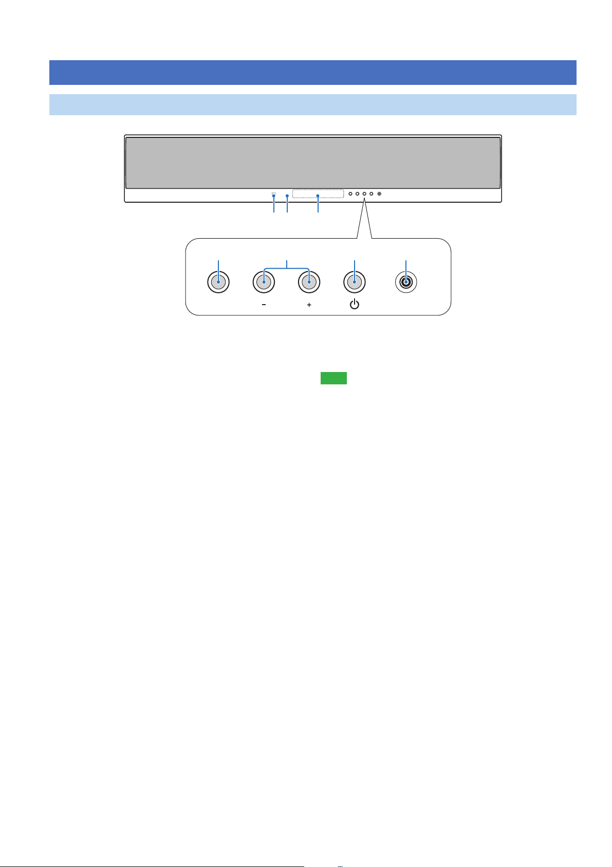
Front panel
Controls and functions
321
5
INPUT VOLUME INTELLIBEAM MIC
1 Remote control sensor
Receives infrared signals from the remote control (page 14).
2 Power LED
Lights up when the power is turned on (page 21).
3 Front panel display
Shows information about the operational status of this unit (page 7).
4 INPUT
Press repeatedly to switch between input sources.
5 VOLUME +/–
Controls the volume level of all audio channels.
Control range: MIN (minimum), 01 to 99, MAX (maximum)
64 7
6 Power (p) key
Turns on the power of this unit or sets it to the standby mode
(page 21).
Note
• In the standby mode, this unit consumes a small amount of power in order to
receive infrared signals from the remote control or to search for HDMI
signals.
7 INTELLIBEAM MIC jack
Connect the supplied IntelliBeam microphone for AUTO SETUP
(page 15).
6 En
Page 7
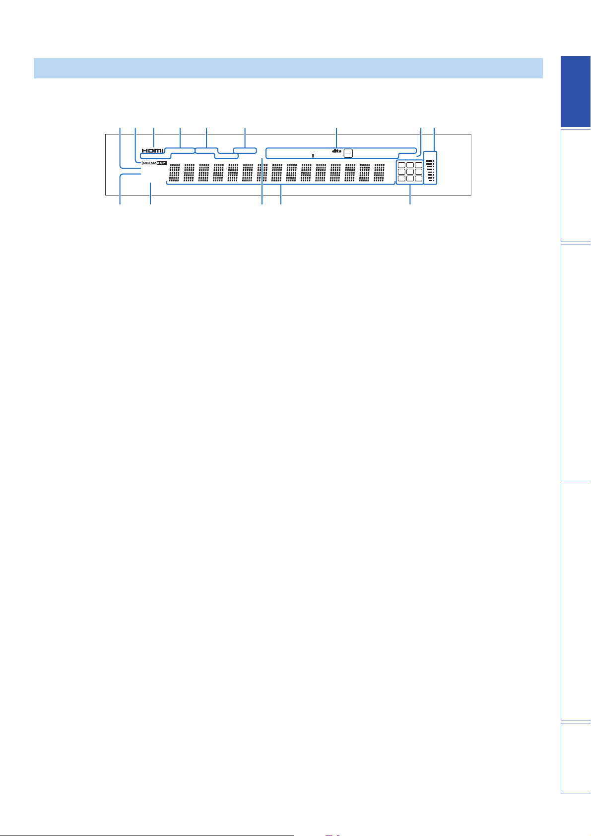
Front panel display
64 5 78921 3
AUTO
MEMORY
UNIVOLUME
ENHANCER
BASS EXT
TUNED STEREO
SIRIUS HD MSTR HI
CATEGORY
q
RECVTRNS
PCM
q
1 UNIVOLUME indicator
Lights up when the UniVolume function is turned on (page 31).
2 CINEMA DSP indicator
Lights up when a sound field program is selected (page 22).
3 HDMI indicator
Lights up when the signal of the selected input source is input from
the HDMI IN jack(s).
4 Tuner indicators
FM: Light up when this unit is tuned into an FM station (page 25).
SIRIUS: MEMORY flashes during the preset operation (page 28).
5 SIRIUS indicators
Light up when this unit is tuned into a SIRIUS Satellite Radio
channel (page 26).
6 Wireless indicators
TRNS Lights up when a wireless connection is established
between the Yamaha wireless subwoofer kit (SWKW10) and this unit (page 13).
RECV Lights up when a wireless connection is established
between the Yamaha wireless transmitter for iPod (PDX50TX) and this unit (page 30).
7 Decoder indicators
Light up when the corresponding decoder operates
(page 21).
DIGITAL PLUS
TRUE HD
q
CA0 B
PL x
q
96
EX
24
ES DSCRT MTRX
dB
RES
O
m
ft
Neo:6
SLEEP
L C R
SL SB SR
EX1 LFE EX2
VOL
D
8 SLEEP indicator
Lights up when the sleep timer is set (page 31).
9 Volume level indicator
Displays the current volume level.
0 ENHANCER indicator
Lights up when the Music Enhancer is selected (page 37).
A BASS EXT indicator
Lights up when the bass extension mode is turned on (page 37).
B PCM indicator
Lights up when this unit is reproducing PCM (Pulse Code
Modulation) digital audio signals.
C Multi-information display
Shows information with alphanumeric characters when you adjust the
parameters of this unit. Current input source and audio output method
are displayed when this unit is turned on.
D Input channel indicators
The channel component of the current input signal is displayed
(page 21).
PREPARATIONINTRODUCTION APPENDIXPLAYBACK FEATURES SETTINGS
7 En
Page 8
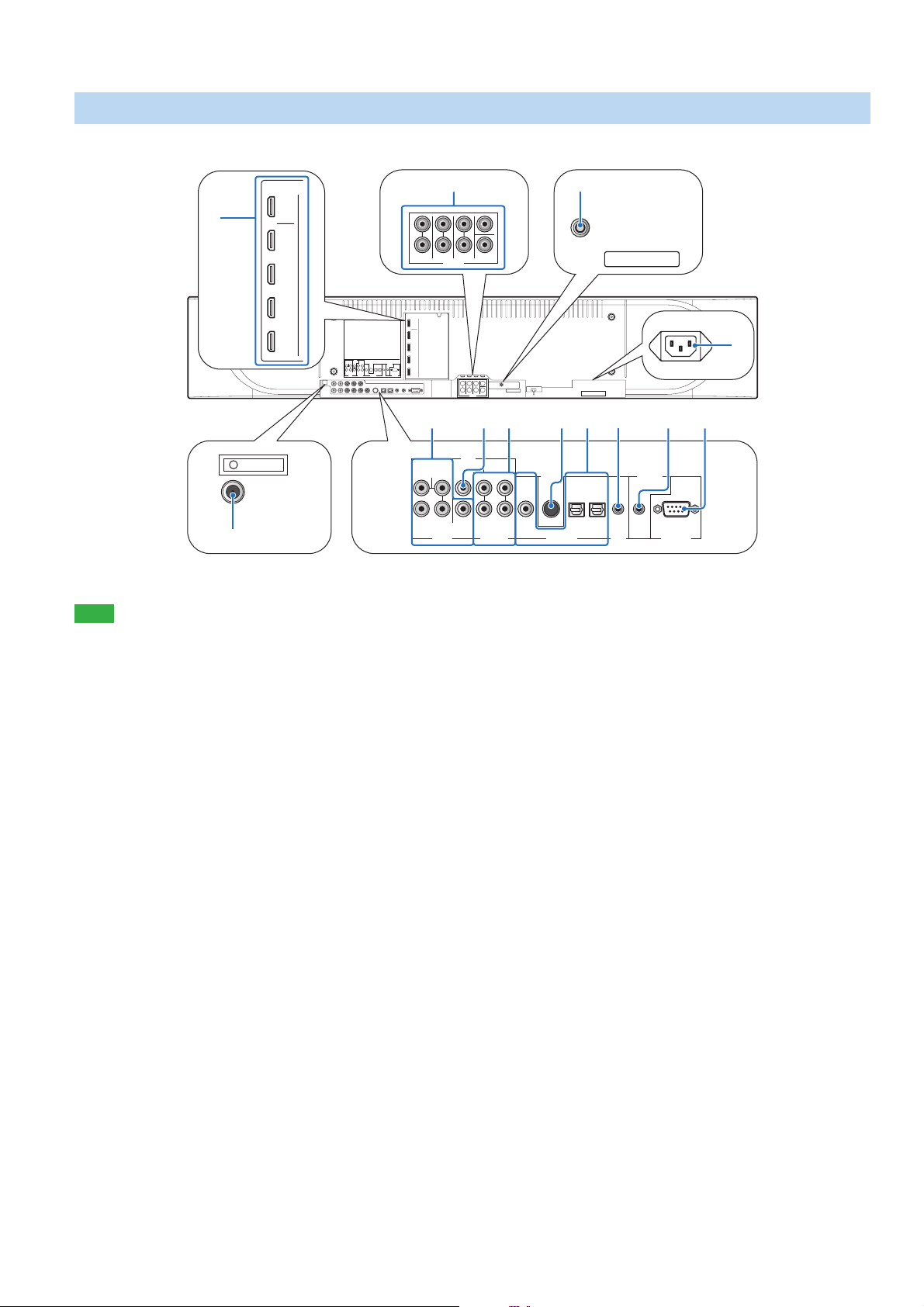
Rear panel
SIRIUS
DIGITAL INAUDIO INVIDEO
B
AUX 1 TVAUX 2AUX 1 TVOUTIN
IR-OUT
A
AC IN
8
IR IN
SYSTEM
CONNECTOR
03 5 7
RS-232C
1
2
HDMI
FM ANTENNA
C
OUT
IN 1
FRONT
SURROUND SUR. BACK
IN 2
IN 3
IN 4
SUB
WOOFER
COMPONENT
SYSTEM
SIRIUS
CONNECTOR
R PB
P
LL
VIDEOVIDEO
Y
RR
AUX 1 TV
AUX 2AUX 1 TVOUTIN
IR IN
RS-232C
DIGITAL INAUDIO INVIDEO
PRE OUT
OUT 1
HDMI
IN 1
IN 2
IN 3
IN 4
CENTER
LRLRL
SUB
R
WOOFER
FRONT
IR-OUT
SURROUND SUR. BACK
PRE OUT
4 6 9
SUB
WOOFER
COMPONENT
Note
• The rear panel illustration shows jacks and their names to help you find them easily. They are not exactly the same as the ones on the actual rear panel of this
unit.
1 HDMI jacks
Connect your HDMI components (page 12).
2 FM ANTENNA jack
Connect the FM antenna (page 14).
3 VIDEO jacks
Connect to the video jacks of your external components (page 12).
4 SUBWOOFER jack
Connect your subwoofer (page 13).
5 AUDIO IN jacks
Connect to the analog audio output jacks of your external
components (page 12).
6 SIRIUS antenna jack
Connect a SiriusConnect tuner (sold separately) (page 26).
7 DIGITAL IN jacks
Connect to the digital audio output jacks of your external components
(page 12).
8 IR IN terminal
This is a control expansion terminal for commercial use only.
9 SYSTEM CONNECTOR terminal
Use to connect a Yamaha subwoofer equipped with a SYSTEM
CONNECTOR terminal to this unit (page 13).
0 RS-232C terminal
This is a control expansion terminal for commercial use only.
A AC IN
Connect the supplied power cable (page 12).
B IR-OUT terminal
This is a control expansion terminal for commercial use only.
C PRE OUT jacks
Connect your external amplifier (page 41).
8 En
Page 9

Remote control
A
B
TV AV
TV AUX 1 AUX 2
HDMI 1 HDMI 2 HDMI 3
HDMI 4 iPod RADIO
ENTER
TAINMENT
CINEMA DSP
ENTER
SETUP RETURN
TV
INPUT MUTE
MEMORY
OFF
STEREO
MENUTOP MENU
ENT
SLEEPINFO
MUSIC
MOVIE
SURROUND
OPTION
TV VOL CH VOLUME
TV
MUTE
UNIVOLUME SUR. DECODE INTELLIBEAM
1 2 3
4 5 6
7 8 9
0 +10
CODE SET
TUNING PRESET CATEGORY
Note
• When operating the keys located on the slide cover (INFO, SLEEP, etc.),
close the slide cover completely before operation.
A Transmission indicator
Lights up when infrared control signals are being output.
B TV (p)
Turns on the power of your TV or set it to the standby mode
(page 42).
B AV (p)
Turns on the power of the selected component or set it to the standby
mode (page 42).
C Power (p) key
Turns on the power of this unit or set it to the standby mode
(page 21).
C
D
E
F
G
H
I
J
K
L
M
N
O
P
Q
R
D Input selector keys
Use to select an input source (page 21). An input source key currently
selected lights up when the remote control is operated.
E CINEMA DSP program keys
Select the CINEMA DSP programs (page 22).
F SURROUND/STEREO
Switches between surround and stereo playback (page 22).
G Cursor ( / / / ) keys, ENTER
Select and adjust menu items.
H TOP MENU
Displays the top menu of a Blu-ray disc or DVD (page 42).
H MENU
Displays the menu of a Blu-ray disc or DVD (page 42).
I OPTION
Displays the option menu (page 32). The remote control turns to
setting mode (ISETUP lights up).
I SETUP
Displays the SETUP menu (page 33). Press and hold to directly enter
the LANGUAGE SETUP menu (page 15). Lights up when the
remote control is turned into the setting mode of the main unit.
I RETURN
Returns to the previous menu screen (page 34).
J CH /
Changes the channels of your TV/recorder (page 42).
K VOLUME +/–
Increases or decreases the volume level of this unit (page 21).
K MUTE
Mutes the sound. (page 21).
L TV operation keys
Use to control your TV (page 42).
M UNIVOLUME
Turns on or off the UniVolume function (page 31).
M SUR.DECODE
Selects a decoder for surround playback (page 24). The remote
control turns to setting mode (ISETUP lights up).
M INTELLIBEAM
Enters the AUTO SETUP menu (page 16). The remote control turns
to setting mode (ISETUP lights up).
N Numeric keys
Use to enter numbers.
O CODE SET
Sets remote control codes for external component operations
(page 42).
P Tuner / external component operation keys
Use to select or preset an FM station or Sirius Satellite Radio channel
or control playback of your external components (pages 25, 26 and
42).
Q SLEEP
Sets the sleep timer (page 31).
R INFO
Displays information about signals currently input to this unit
(page 32).
PREPARATIONINTRODUCTION APPENDIXPLAYBACK FEATURES SETTINGS
9 En
Page 10
PREPARATION
Installation
This section describes a suitable installation location to install this unit using a wall mount bracket, a rack, a table top stand or a floor stand. To
achieve desired surround sound effects, install this unit where there are no objects such as furniture obstructing the path of sound beams
(page 11). Depending on your installation environment, connections with external components (page 12) should be done before installation.
Notes
• Make sure you leave an adequate amount of ventilation space so that heat
can escape. We recommend installing this unit using a wall mount bracket, a
rack, a table top stand or a floor stand.
• Be sure to install this unit where it will not fall subject to vibrations, such as
from an earthquake, and where it is out of the reach of children.
• When using a cathode-ray tube (CRT) TV, do not install this unit directly
above your TV.
• If the picture on your TV screen becomes blurred or distorted, we
recommend moving this unit away from your TV.
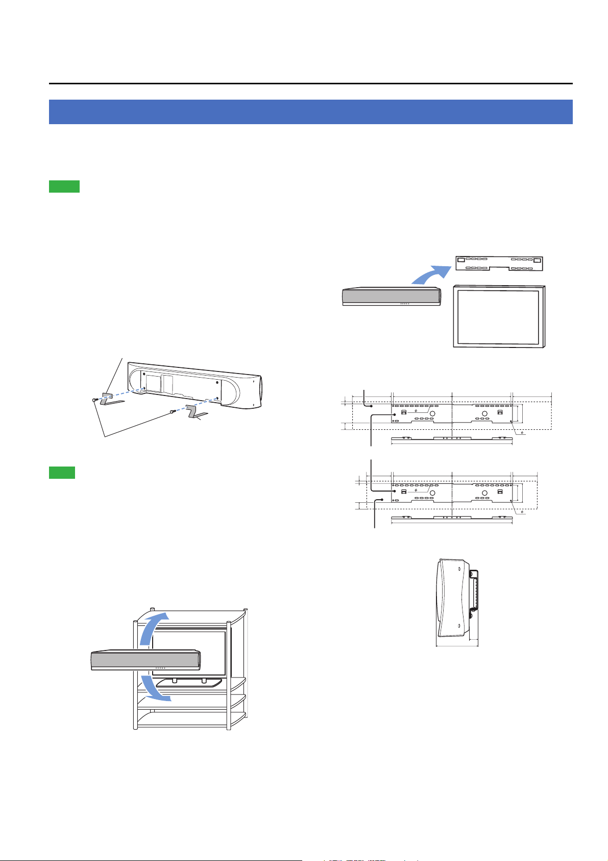
■ Attach the stands
Attach the supplied stands to this unit as shown below. Make sure that
you attach the left and right stands correctly. These stands are
unnecessary if you use the optional wall mount bracket.
Right stand (supplied)
Left stand (supplied)
Screws (for stands, supplied)
Note
• Depending on a rack, table top stand, or floor stand, the stands may not be
necessary.
■ Using a rack
You can install this unit either above or under your TV in a
commercially available rack.
It should be large enough to allow adequate ventilation space around
this unit and strong enough to support the weight of both this unit and
your TV.
■ Using a wall mount bracket
You can use the optional wall mount bracket (such as SPM-K30) to
mount this unit on the wall in your listening room.
Attachment of the wall mount bracket: refer to the owner's manual
supplied with the wall mount bracket.
Wall mount bracket
This unit
TV
Dimensions when using SPM-K30
YSP-5100
235 355 235355
26
74
SPM-K30 (Option)
150 355 150355
26
74
YSP-4100
24- 7x22
730
24- 7x22
730
92
4- 7
92
4- 7
112
112
(mm)
10 En
When this unit is installed above your TV
TV
This unit
When this unit is installed under your TV
18
107
(mm)
■ Using a table top stand or a floor stand
You can mount both your TV and this unit on a commercially
available table top stand or floor stand.
Page 11
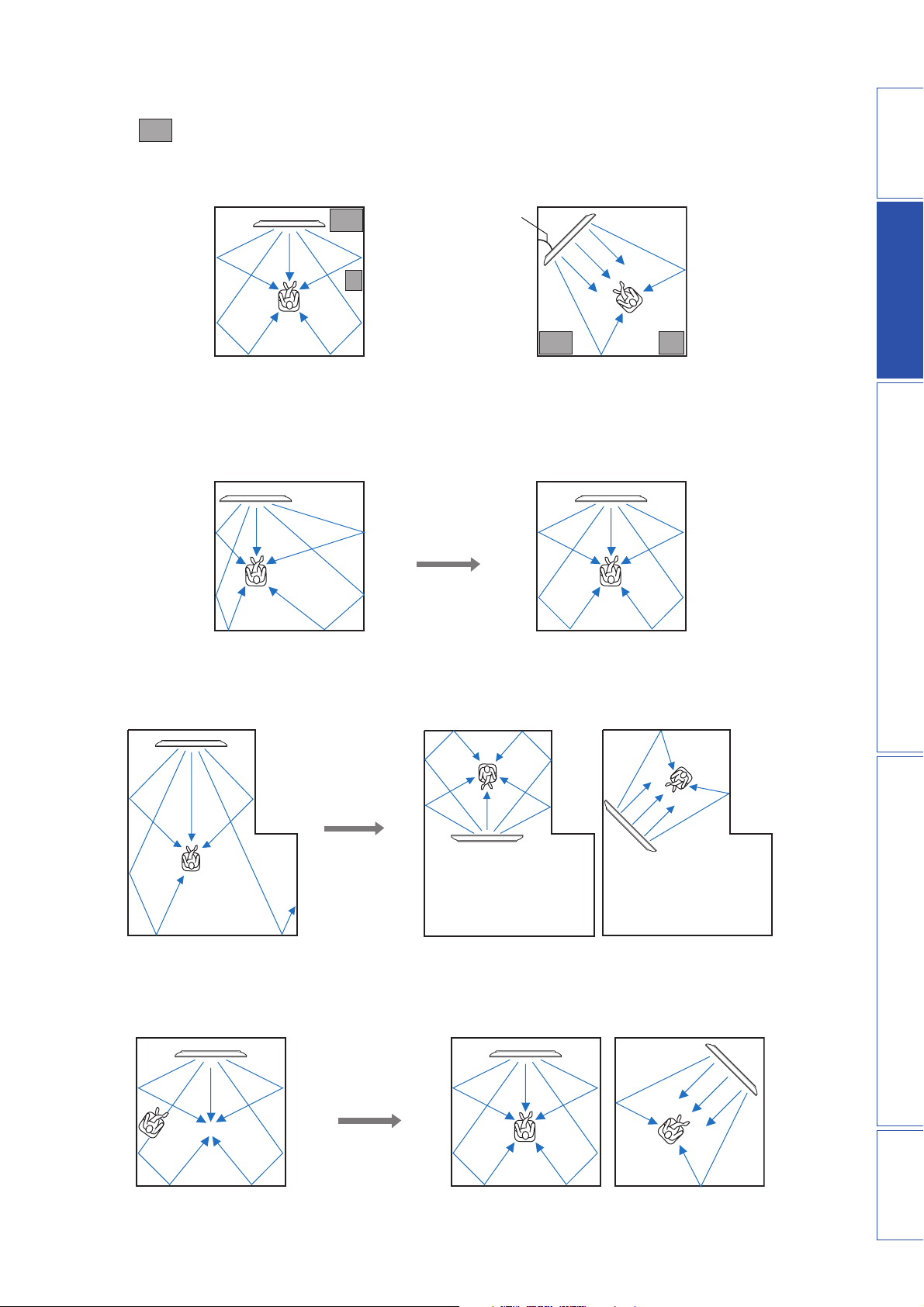
■ Ideal installation condition
: Object such as furniture
Parallel installation (with 5Beam)
■ For better listening environment
Example 1
Install this unit as close to the exact center of the wall as possible.
Corner installation (with Stereo+3Beam)
40° to 50°
PREPARATIONINTRODUCTION APPENDIXPLAYBACK FEATURES SETTINGS
Example 2
Install this unit so that the sound beams can be reflected off the walls.
Example 3
Install this unit as close to the exact front of your normal listening position as possible.
11 En
Page 12
Connections
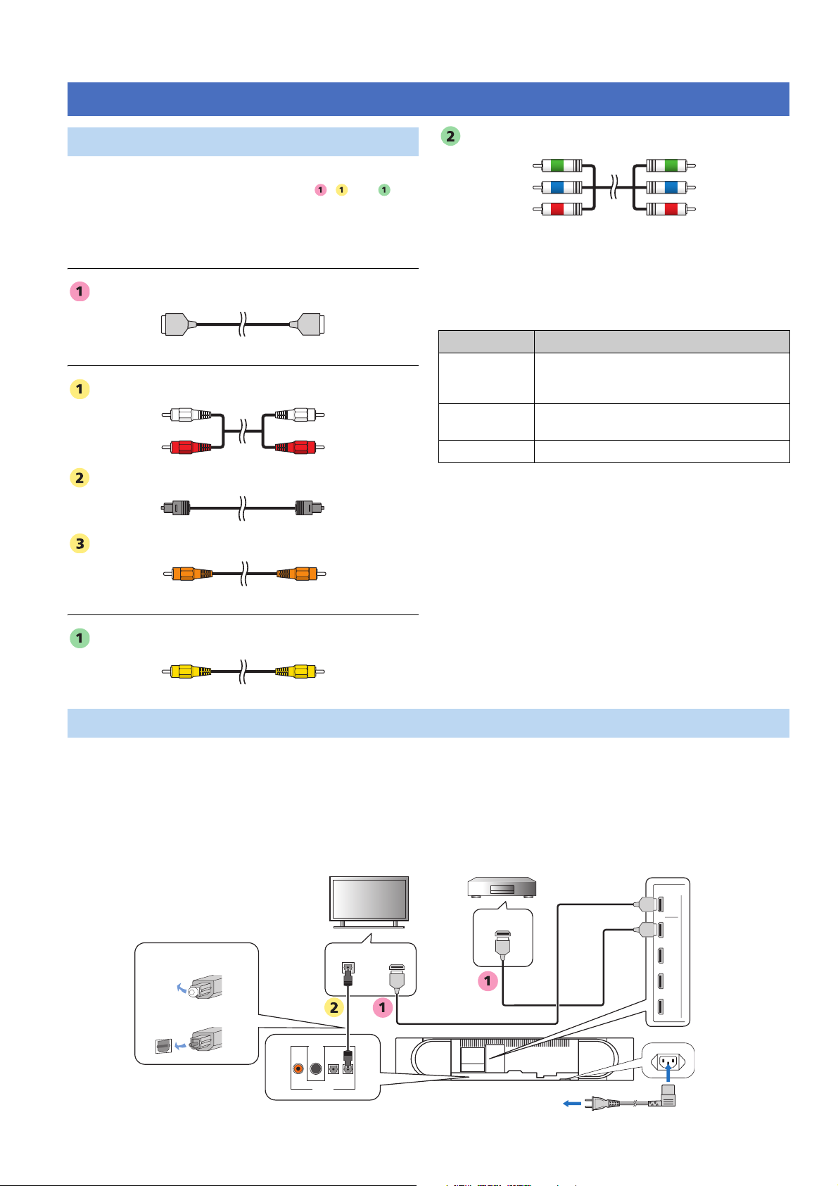
Before connecting components
■ Cables used for connections
The symbols on the left of cable names (such as , , and )
correspond with the symbols described in “Connecting your TV and
Blu-ray disc player” (page 12) and “Connecting audio video
components” (page 13).
For audio and video
HDMI cable
For audio
Audio pin cable (supplied)
Optical cable (supplied)
Digital audio pin cable (supplied)
Component video pin cable
■ Information on HDMI
An HDMI cable can transmit both audio and video signals at the
same time. If your TV and other components have HDMI jacks, use
HDMI cables for simpler and easier connections.
See also: “Using the HDMI control function” (page 31), “INPUT
MENU” (page 38)
Input source Audio signal type
Blu-ray disc
HD DVD
DVD video Dolby Digital, DTS, 2-channel PCM, multi-channel
DVD audio 2-channel PCM, multi-channel PCM
y
• This unit automatically converts input video signals and outputs the signals
from the HDMI OUT jack.
• The HDMI of this unit supports High-Bandwidth Digital Content Protection
(HDCP),
• We recommend that you use an HDMI cable shorter than 5 m (16 ft) with
the HDMI logo printed on it.
Dolby Digital, Dolby Digital Plus, Dolby TrueHD,
DTS, DTS-HD High Resolution Audio, DTS-HD
Master Audio, 2-channel PCM, multi-channel PCM
PCM
■ Priority order for audio input signals
For video
Video pin cable (supplied)
When digital and analog audio signals are simultaneously input from
a single source component, this unit plays back digital audio signals
by priority. For example, if audio signals are input to the DIGITAL
IN (AUX 1) and AUDIO IN (AUX 1) jacks simultaneously, this unit
plays back audio signals input to the DIGITAL IN (AUX 1) jack
when “AUX1” is selected as the input source.
Connecting external components
Connect external components (TV, Blu-ray disc player, etc.) to this unit. Do not plug the power supply cable into an AC wall outlet until all
connections are complete.
■ Connecting your TV and Blu-ray disc player
The following connection example shows a way to connect your TV and Blu-ray disc player by using the HDMI jacks. When you connect them
by using the other jacks, refer to “Connecting audio and video components” (page 13). The symbols beside the cables correspond with the
symbols described in “Cables used for connections” (page 12).
Blu-ray disc player
HDMI
output
OUT
HDMI
IN 1
IN 2
IN 3
1. Pull out the cap
(if attached)
Optical digital
output
TV
HDMI
input
12 En
2. Check the direction
SIRIUS
DIGITAL IN
IN 4
AUX 1 TVAUX 2
Power cabl e
to AC wall outlet
Page 13
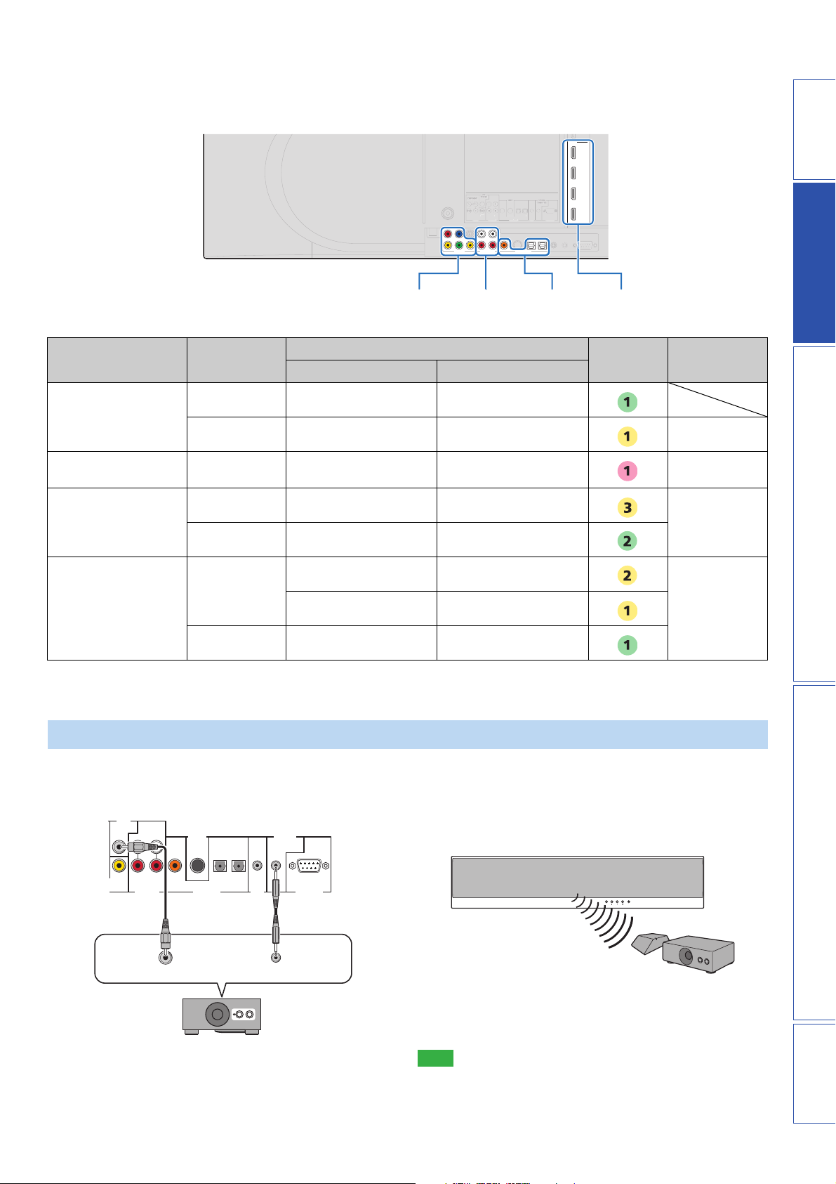
■ Connecting audio and video components
A
UX 1
TV
A
UX 2AUX 1
TV
IN
DIGIT
R
C
Determine the connection types depending on the jacks available on this unit and your external components. The symbols in the following table
correspond with the symbols described in “Cables used for connections” (page 12).
HDMI
IN 1
IN 2
IN 3
OUT
UDIO INVIDEO
DIGITAL INAUDIO INVIDEO
IN 4
S-232
PREPARATIONINTRODUCTION APPENDIXPLAYBACK FEATURES SETTINGS
External component Signal type
VIDEO IN/OUT
jacks
Jacks to use
On external component On this unit
AUDIO IN
jacks
DIGITAL IN
jacks
HDMI IN
jacks
Cable to
use
Input selection
key
TV Video Composite video input VIDEO OUT
Audio Analog audio output AUDIO IN (TV) TV
External component
Audio/video HDMI output HDMI IN 1-4 HDMI1-4
with HDMI output
External component
Audio Coaxial digital output DIGITAL IN (AUX 2) AUX2
with component video
output
External component
Video Component video output VIDEO IN (COMPONENT)
Audio Optical digital output DIGITAL IN (AUX 1) AUX1
with composite video
output
Analog audio output AUDIO IN (AUX 1)
Video Composite video output VIDEO IN (VIDEO)
y
• Video signals input from the VIDEO IN (VIDEO) jack can be output not only to the VIDEO OUT jack but also the HDMI OUT jack. Video signals input from
the VIDEO IN (COMPONENT) jacks are output to the HDMI OUT jack.
Connecting a subwoofer
Wireline connection
Connect the monaural input jack on your subwoofer to the
SUBWOOFER jack on this unit.
SUB
WOOFER
SIRIUS
AUX 1 TVAUX 2AUX 1 TVOUT
DIGITAL INAUDIO IN
Monaural input System connector
y
• If the subwoofer is connected by using a system type connection, changing
the power mode of this unit controls the power mode of the subwoofer
(Yamaha subwoofer).
IR IN
SYSTEM
CONNECTOR
RS-232C
Wireless connection
You can make a wireless connection of your subwoofer by using the
Yamaha wireless subwoofer kit (SWK-W10). About SWK-W10,
refer to “Safety and Accessory Information” (separate booklet).
See also: “WIRELESS SETUP” (page 39)
INPUT VOLUME INTELLIBEAM MIC
Subwoofer
SWK-W10
y
• For proper transmission, you need to set the group IDs of this unit and
SWK-W10 to the same value. For the Group ID settings, refer to “Group
ID” (page 39) and “Safety and Accessory Information (separate booklet)”.
Note
• Be sure to use the product only in the country in where it was purchased.
13 En
Page 14
TV AV
TV AUX 1 AUX 2
HDMI 1 HDMI 2 HDMI 3
HDMI 4 iPod RADIO
ENTER
TAINMENT
MUSIC
MOVIE
CINEMA DSP
SURROUND STEREO
Connecting the FM antenna
Connect the supplied FM antenna or your antenna to the FM ANTENNA jack on this unit.
Antenna
OFF
ENTER
ENTER
SETUP RETURN
TV
INPUT MUTE
1 2 3
4 5 6
7 8 9
0 +10
MEMORY
MENUTOP MENU
ENT
SLEEPINFO
OPTION
OPTION SETUP RETURN
TV VOL CH VOLUME
TV
MUTE
UNIVOLUME SUR. DECODE INTELLIBEAM
CODE SET
TUNING PRESET CATEGORY
G
I
Preparing the remote control
Note
• Before installing batteries or using the remote control, make
sure that you read precautions on the remote control and
batteries in “Safety and Accessory Information” (separate
booklet).
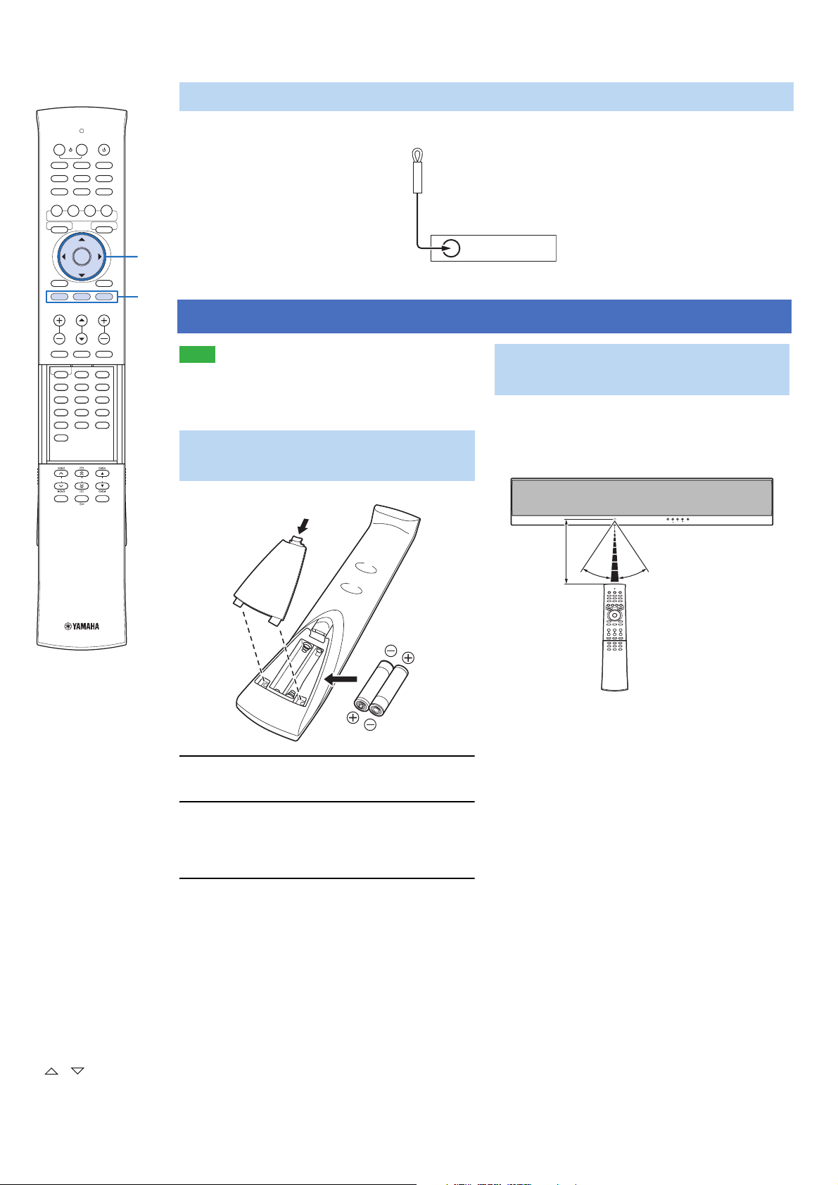
Installing batteries in the remote control
Pull and hold
FM ANTENNA
Operation range of the remote control
The remote control transmits a directional infrared beam.
Use the remote control within 6 m (20 ft) of this unit and
point it toward the remote control sensor of this unit
during operation.
INPUT VOLUME INTELLIBEAM MIC
Within
6m (20ft)
30° 30°
GENTER
G /
ISETUP
14 En
1 Pull and hold the tab on the battery cover
and then open the cover.
2 Insert the two supplied batteries (R03P, UM4,
AAA) into the battery compartment.
Make sure you insert the batteries according to the
polarity markings (+/–).
3 Close the battery cover.
Page 15
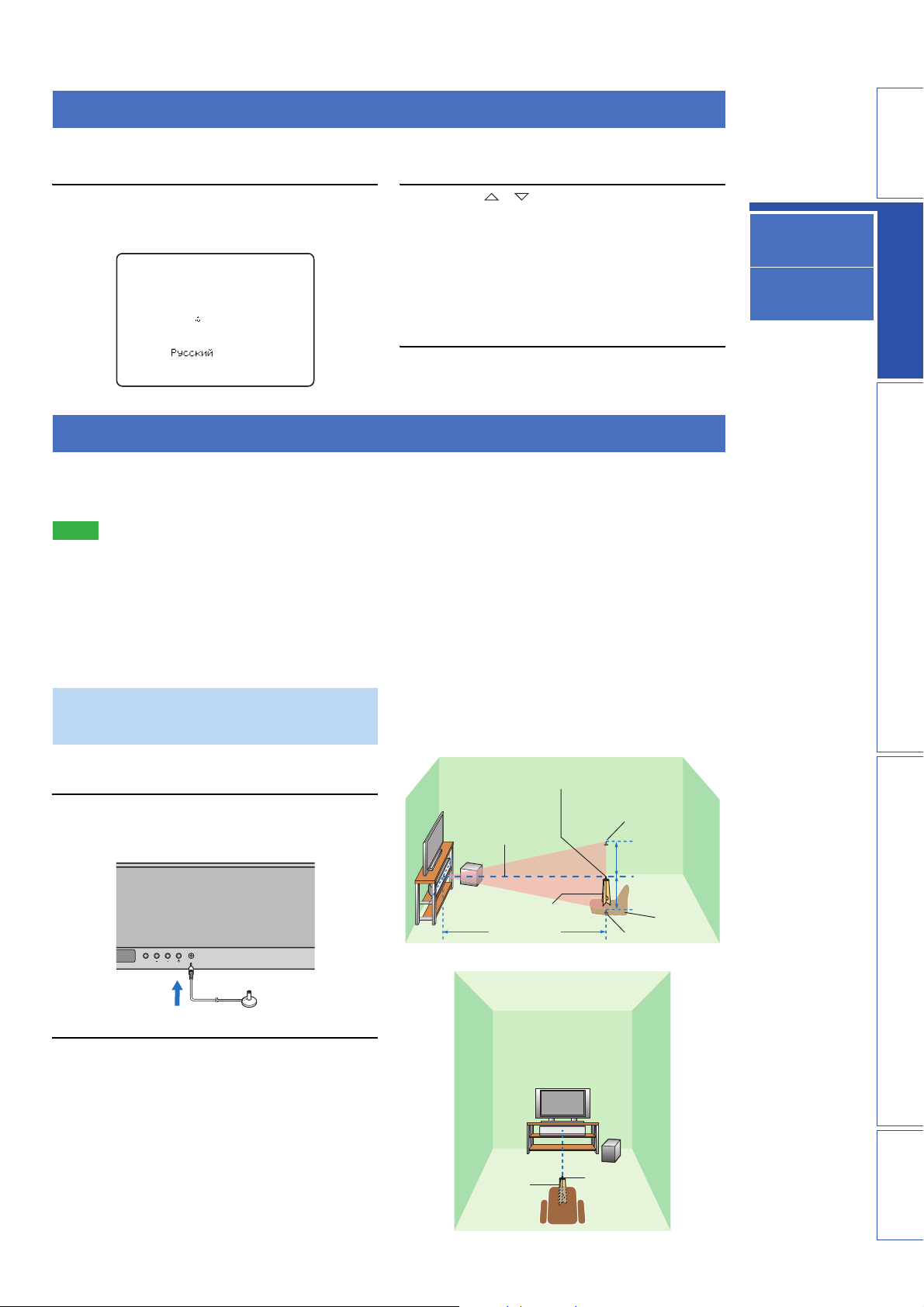
Changing OSD language
You can select an OSD language among English, German, French, Spanish, Italian, Dutch and Russian. Before operating
the following steps, select this unit as the video input on your TV.
1 Press and hold ISETUP until the
“LANGUAGE SETUP” menu appears on your
TV.
2 Press G / to select the desired
language and then press GENTER.
Choices: ENGLISH (English), DEUTSCH (German),
Français (French), ESPAÑOL (Spanish),
3)LANGUAGE SETUP
ENGLISH
.
DEUTSCH
Francais
ESPANOL
ITALIANO
NEDERLANDS
p
[ ]/[ ]:Up/Down
p
[ENTER]:Enter
Initial setting: ENGLISH (English)
3 To exit from the menu, press ISETUP.
ITALIANO (Italian), NEDERLANDS (Dutch),
Русский (Russian)
AUTO SETUP (IntelliBeam)
This unit creates a sound field by reflecting sound beams off the walls of your listening room and by broadening the
cohesion of all the channels. Just as you would arrange the speaker position of other audio systems, you need to set the
beam angle to enjoy the best possible sound from this unit.
Notes
• After you have completed the AUTO SETUP procedure, be sure to disconnect the IntelliBeam microphone.
• The IntelliBeam microphone is sensitive to heat.
– Keep the IntelliBeam microphone away from direct sunlight.
– Do not place the IntelliBeam microphone on top of this unit.
• You cannot use the AUTO SETUP when “PREOUT” is selected in “SOUND OUT” (page 38).
• You cannot run the AUTO SETUP while playing back the iPod/iPhone by using PDX-50TX. To run the AUTO SETUP, stop playback
and then disconnect the iPod/iPhone from PDX-50TX. About PDX-50TX, refer to “Safety and Accessory Information” (separate
booklet).
Changing OSD
language
AUTO SETUP
(IntelliBeam)
Using the system
memory
PREPARATIONINTRODUCTION APPENDIXPLAYBACK FEATURES
Installing the IntelliBeam microphone
Follow the procedure below to connect the IntelliBeam
microphone to this unit and place it in a proper location.
1 Connect the supplied IntelliBeam
microphone to the INTELLIBEAM MIC jack on
the front panel.
INPUT VOLUME INTELLIBEAM MIC
INTELLIBEAM MIC
2 Place the IntelliBeam microphone on a flat
level surface at your normal listening
position.
Place the IntelliBeam microphone on the extended
center line of this unit and 1.8 m (6.0 ft) or more
away from it. Also, make sure place the IntelliBeam
microphone within 1 m (3.3 ft) upper or lower from
the center height of this unit.
y
• Use the supplied cardboard microphone stand or a tripod
to place the IntelliBeam microphone at the same height as
your ears would be when you are seated.
IntelliBeam microphone
Center height of
this unit
Cardboard
microphone stand
1.8 m (6.0 ft)
or more
Center line
Cardboard
microphone
stand
Upper limit
Within 1 m (3.3 ft)
Within 1 m (3.3 ft)
Lower limit
IntelliBeam
microphone
Listening
position
SETTINGS
15 En
Page 16
TV AV
TV AUX 1 AUX 2
HDMI 1 HDMI 2 HDMI 3
HDMI 4 iPod RADIO
ENTER
TAINMENT
MUSIC
MOVIE
CINEMA DSP
SURROUND STEREO
ENTER
ENTER
SETUP RETURN
TV
INPUT MUTE
1 2 3
4 5 6
7 8 9
0 +10
MEMORY
MENUTOP MENU
ENT
SLEEPINFO
OPTION
OPTION SETUP RETURN
TV VOL CH VOLUME
TV
MUTE
UNIVOLUME SUR. DECODE INTELLIBEAM
CODE SET
TUNING PRESET CATEGORY
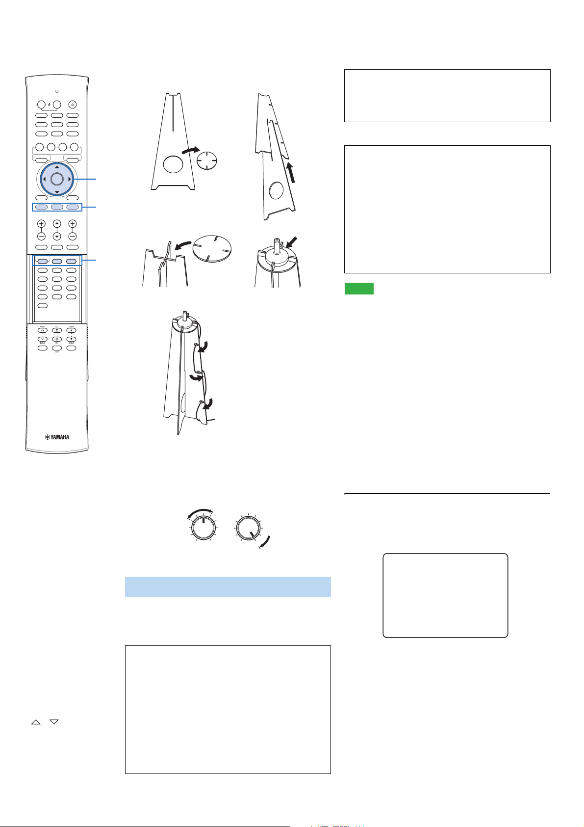
■ Assembling the supplied cardboard
microphone stand
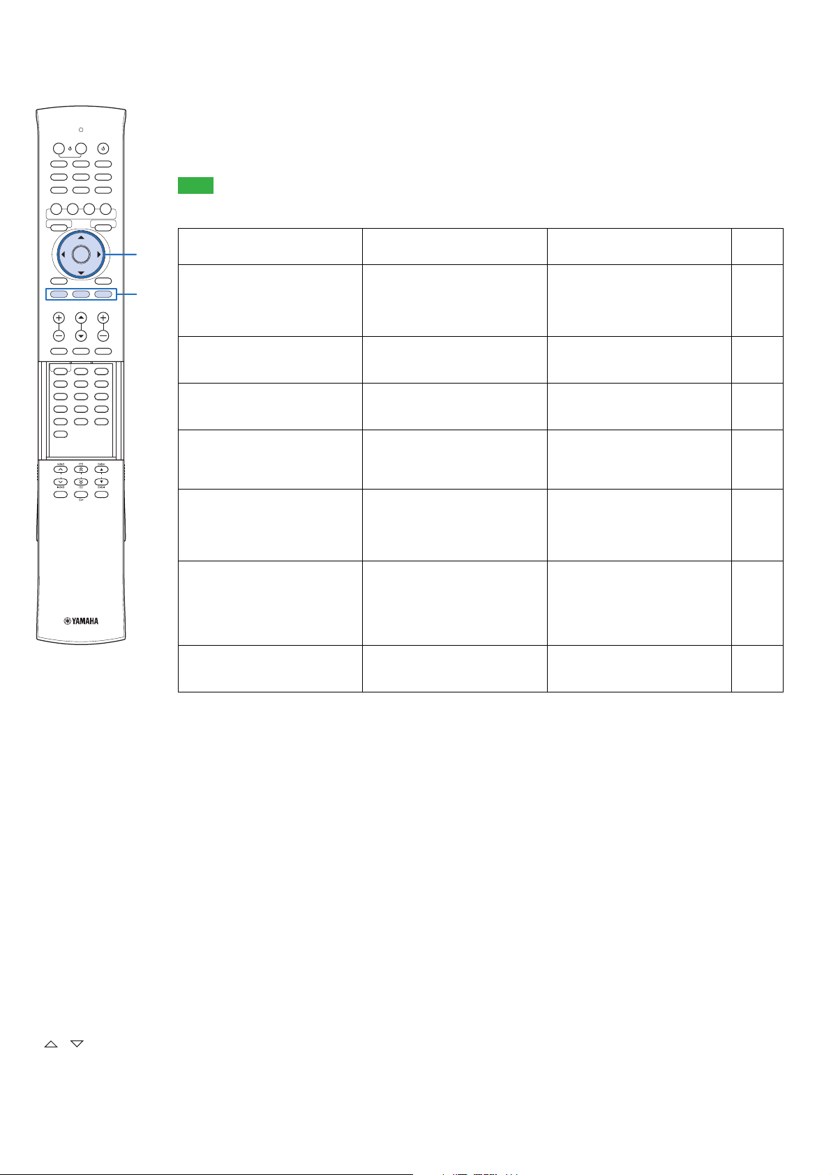
“BEAM OPTIMZ ONLY”
(Beam optimization only)
Use to optimize the beam angle so that the parameter
12
best matches your listening environment.
This menu takes about one minute.
OFF
Remove
Fit in
“SOUND OPTIMZ ONLY”
(Sound optimization only)
Use to optimize the beam delay, volume, and quality so
G
that the parameters best match your listening
environment. You must optimize the beam angle with
“BEAM OPTIMZ ONLY” before starting “SOUND
I
OPTIMZ ONLY”. It is recommended that you should
select this optimization feature in the following cases:
34
Fit in
Place horizontally
• If you have opened or closed the curtains in your
listening room before using this unit
• If you have manually set the beam angle.
M
This menu takes about three minutes.
Notes
• It is normal for loud test tones to be output during the AUTO
5
SETUP procedure. Make sure that there are no children around
in the listening room while the AUTO SETUP procedure is in
Run through
progress.
• Make sure that your listening room is as quiet as possible. For
accurate measurement, turn off air conditioner or other devices
that make noises.
• To achieve the best results possible, vacate your listening room
until the AUTO SETUP procedure is completed so that you may
not obstruct the path of sound beams.
• If there are curtains in your listening room, we recommend
following the procedure below.
1. Open the curtains to improve sound reflection.
2. Run “BEAM OPTIMZ ONLY”.
3. Close the curtains.
y
• If a subwoofer with adjustable volume and crossover frequency
controls is connected to this unit, turn it on, set the volume to
about half way and then set the crossover frequency to the
maximum as shown below.
VOLUME
CROSSOVER
HIGH CUT
4. Run “SOUND OPTIMZ ONLY”.
y
• To return to the previous screen while using SET MENU, press
IRETURN.
1 Press ISETUP.
The remote control keys to be used and available
operations in each step are displayed at the bottom of
MIN MAX MIN
Subwoofer
MAX
the screen.
SET MENU
.
;MEMORY
Using AUTO SETUP (IntelliBeam)
You can select one of the following AUTO SETUP types
depending on your purpose.
“BEAM+SOUND OPTIMZ”
;AUTO SETUP
;MANUAL SETUP
;SOUND SET MENU
;SOUND OUT MENU
;INPUT MENU
;DISPLAY MENU
p
[ ]/[ ]:Up/Down
p
[ENTER]:Enter
GENTER
G /
IRETURN
ISETUP
MINTELLIBEAM
16 En
(Beam optimization and sound optimization)
Use to optimize the beam angle, delay, volume, and
quality so that the parameters best match your listening
environment. It is recommended that you should select
this optimization feature in the following cases:
• If you make settings for the first time
• If the unit has been relocated
• If your listening room has been restructured
• If the objects in your listening room (furniture, etc.)
have been rearranged
This menu takes about three minutes.
y
• You can also start the “BEAM+SOUND OPTIMZ”
procedure simply by holding down MINTELLIBEAM for
more than two seconds. In this case, proceed to step 4.
Page 17

2 Press G / to select “AUTO SETUP” and
then press GENTER.
B)AUTO SETUP
1)BEAM+SOUND OPTIMZ
2)BEAM OPTIMZ ONLY
3)SOUND OPTIMZ ONLY
p
p
[ ]/[ ]:Up/Down
[ENTER]:Enter
3 Press G / to select “BEAM+SOUND
OPTIMZ”, “BEAM OPTIMZ ONLY” or “SOUND
OPTIMZ ONLY” and then press GENTER.
AUTO SETUP
PREPARATION & CHECK
Please connect the MIC.
Please place the MIC at least
1.8m/6ft away from the unit.
The MIC should be set
at ear level when seated.
Measurement takes about 3min.
After [ENTER] is pressed,
please leave the room.
[ENTER]:Start [RETURN]:Cancel
4 Prepare to leave the room.
The best setting may not be done if you are in the
room. Prepare to leave the room in 10 seconds after
pressing GENTER in step 5.
y
• Wait outside the room during the AUTO SETUP
procedure.
• The AUTO SETUP procedure takes about 3 minutes.
• To cancel the AUTO SETUP procedure after it is started,
press IRETURN.
5 Press GENTER to start the AUTO SETUP
procedure and then leave the room within 10
seconds.
AUTO SETUP START
Will begin in 10sec
Please leave the room
y
• If “ENVIRONMENT CHECK [FAILED]” is displayed,
refer to “Error messages for AUTO SETUP” (page 18),
press IRETURN, and then run the AUTO SETUP
procedure again.
• If “SUBWOOFER :NOT APPLICABLE” is displayed
even though a subwoofer is connected to this unit and
turned on, check the connection and then increase the
volume level of the subwoofer and run the AUTO SETUP
procedure again.
• Depending on the environment of your listening room, the
beam angles of front right and left and surround left and
right may be set to the same value even if “BEAM MODE
:5 BEAM” is displayed as a result.
6 Press GENTER to confirm the results.
The menu screen disappears in two seconds.
AUTO SETUP COMPLETE
Please remove the MIC from
the unit and the listening
position.
y
• If you do not want to reflect the results, press IRETURN.
7 Disconnect the IntelliBeam microphone.
INPUT VOLUME INTELLIBEAM MIC
The measurement results are stored in the internal
memory of this unit until you run the AUTO SETUP
procedure again or configure the settings manually.
Changing OSD
language
AUTO SETUP
(IntelliBeam)
Using the system
memory
PREPARATIONINTRODUCTION APPENDIXPLAYBACK FEATURES
**--------
[RETURN]:Cancel
The setup screen automatically changes during the
AUTO SETUP procedure.
If an error occurs, an error buzzer sounds and an error
message is displayed. For details on error messages,
see “Error messages for AUTO SETUP” (page 18).
If the AUTO SETUP procedure is complete, this unit
rings the chimes.
XXXXXXXXSHOW RESULTXXXXXXXXXX
MEASUREMENT COMPLETE
BEAM MODE :5Beam/Plus2
SUBWOOFER :YES
[ENTER]:Save set-up.
[RETURN]:Do not save set-up.
SETTINGS
17 En
Page 18
TV AV
TV AUX 1 AUX 2
HDMI 1 HDMI 2 HDMI 3
HDMI 4 iPod RADIO
ENTER
TAINMENT
MUSIC
MOVIE
CINEMA DSP
SURROUND STEREO
ENTER
ENTER
SETUP RETURN
TV
INPUT MUTE
1 2 3
4 5 6
7 8 9
0 +10
MEMORY
MENUTOP MENU
ENT
SLEEPINFO
OPTION
OPTION SETUP RETURN
TV VOL CH VOLUME
TV
MUTE
UNIVOLUME SUR. DECODE INTELLIBEAM
CODE SET
TUNING PRESET CATEGORY
■ Error messages for AUTO SETUP
If an error message is displayed on your TV, check the error message list to solve the problem and then follow the
procedure below.
[ERROR E-1]: Press GENTER to run the AUTO SETUP procedure again or IRETURN to cancel the operation
Other errors: Press IRETURN to cancel the operation and then run the AUTO SETUP procedure again.
OFF
G
I
Note
If the problem is difficult to be solved, configure the settings manually in “MANUAL SETUP” (page 34).
Error message Cause Remedy
ERROR E-1
Please test in quieter environment.
ERROR E-2
No MIC detected. Please check
MIC connection and re-try.
ERROR E-3
Unexpected control is detected.
Please re-try.
ERROR E-4
Please check MIC position. MIC
should be set in front of the unit
and re-try.
ERROR E-5
Please check MIC position. MIC
should be set above 1.8m/6.0ft and
re-try.
ERROR E-6
Volume level is lower than
expected. Please check MIC
position/connection and re-try.
ERROR E-7
Unexpected error happened.
Please re-try.
There is too much unwanted noise in
your listening room.
Make sure that your listening room is as
quiet as possible. You may want to
choose certain hours during the day
when there is not much noise coming
from outside.
The IntelliBeam microphone is not
connected to this unit or disconnected
Connect the IntelliBeam microphone to
this unit firmly.
during the AUTO SETUP procedure.
Some other operations were performed
on this unit while the AUTO SETUP
procedure was in progress.
The IntelliBeam microphone is not
placed in front of this unit.
Do not perform any other operations
while the AUTO SETUP procedure is in
progress.
Make sure that the IntelliBeam
microphone is installed in front of this
unit.
The IntelliBeam microphone is not
placed in the right distance from this
unit.
Make sure that the IntelliBeam
microphone is installed more than 1.8 m
(6.0 ft) from the front of this unit and
within 1 m (3.3 ft) from the center height
of this unit.
The IntelliBeam microphone cannot
collect the sound produced by this unit
because the sound output level is too low.
Make sure that the IntelliBeam
microphone is firmly connected to this
unit and placed in a proper location. If
the problem persists, contact the nearest
authorized Yamaha service center for
assistance.
An internal system error occurred. Repeat the AUTO SETUP procedure.
See
page
—
15
—
15
15
15
—
GENTER
G /
IRETURN
ISETUP
18 En
Page 19

Using the system memory
You can save the current beam and sound settings in the system memory of this unit. It is handy to save certain settings
according to the varying conditions of your listening environment. For example, if there are curtains in the path of sound
beams, the effectiveness of the sound beams will vary depending on whether the curtains are open or closed.
y
• If there are curtains in your listening room, we recommend following the procedure below.
1. While the curtains are open, run “BEAM+SOUND OPTIMZ” (page 16) and then save the settings to “MEMORY1”.
2. While the curtains are closed, run “SOUND OPTIMZ ONLY” (page 16) and then save the settings to “MEMORY2”.
Changing OSD
language
PREPARATIONINTRODUCTION APPENDIXPLAYBACK FEATURES
Saving settings
1 Press ISETUP.
SET MENU
.
;MEMORY
;AUTO SETUP
;MANUAL SETUP
;SOUND SET MENU
;SOUND OUT MENU
;INPUT MENU
;DISPLAY MENU
p
[ ]/[ ]:Up/Down
p
[ENTER]:Enter
2 Press GENTER.
A)MEMORY
1)LOAD
2)SAVE
p
p
[ ]/[ ]:Up/Down
[ENTER]:Enter
3 Press G / to select “SAVE” and then
press GENTER.
5 Press GENTER.
The current beam and sound settings are saved to the
selected memory number.
2)MEMORY SAVE
MEMORY1 Saving...
Loading settings
1 Press ISETUP.
SET MENU
.
;MEMORY
;AUTO SETUP
;MANUAL SETUP
;SOUND SET MENU
;SOUND OUT MENU
;INPUT MENU
;DISPLAY MENU
p
[ ]/[ ]:Up/Down
p
[ENTER]:Enter
2 Press GENTER.
AUTO SETUP
(IntelliBeam)
Using the system
memory
2)MEMORY SAVE
a)MEMORY1
b)MEMORY2
c)MEMORY3
p
p
[ ]/[ ]:Up/Down
[ENTER]:Enter
4 Press G / to select the desired
memory number and then press GENTER.
2)MEMORY SAVE
MEMORY1 Save Now?
[ENTER]:Enter
y
• If system settings are already stored in the selected memory
number, this unit overwrites the old settings.
A)MEMORY
1)LOAD
2)SAVE
p
p
[ ]/[ ]:Up/Down
[ENTER]:Enter
3 Press GENTER again.
1)MEMORY LOAD
a)MEMORY1
b)MEMORY2
c)MEMORY3
p
p
[ ]/[ ]:Up/Down
[ENTER]:Enter
SETTINGS
19 En
Page 20

TV AV
TV AUX 1 AUX 2
TV AUX 1 AUX 2
HDMI 1 HDMI 2 HDMI 3
HDMI 1 HDMI 2 HDMI 3
HDMI 4 iPod RADIO
HDMI 4 iPod RADIO
ENTER
TAINMENT
MUSIC
MOVIE
CINEMA DSP
SURROUND STEREO
ENTER
ENTER
SETUP RETURN
TV
INPUT MUTE
1 2 3
4 5 6
7 8 9
0 +10
MEMORY
MENUTOP MENU
MUTE
ENT
SLEEPINFO
OPTION
TV VOL CH VOLUME
TV
MUTE
UNIVOLUME SUR. DECODE INTELLIBEAM
CODE SET
TUNING PRESET CATEGORY
4 Press G / to select the memory
number to be loaded and then press
GENTER.
C
D
OFF
G
1)MEMORY LOAD
MEMORY1 Load Now ?
Push [ENTER] to Load
5 Press GENTER.
The beam and sound settings saved in the selected
K
memory number are loaded.
1)MEMORY LOAD
MEMORY1 Loading...
CPowe r
DAUX1/2
DHDMI1
DHDMI1-4
DInput selector keys
DTV
GENTER
G /
KMUTE
KVOLUME +/–
20 En
Page 21

PLAYBACK FEATURES
Playback
INTRODUCTION SETTINGS APPENDIXPLAYBACK FEATURES
Playing back sources
This section describes how to playback source input from
your external components. For details on your external
components, refer to the owner’s manual supplied with
each component.
1 Press CPower (p) key to turn on this unit.
2 Turn on external components (TV, Blu-ray
disc player, etc.) connected to this unit.
3 Press one of the DInput selector keys to
select an external component as an input
source.
Input source name
HDMI1
y
• You can change the input source name displayed on the
front panel display (page 38).
4 Start playback of the external component
that you have selected as the input source,
or select a radio station on the tuner.
• FM tuning (page 25)
• Playing back iPod/iPhone (page 30)
5 Press KVOLUME +/– to adjust the volume.
Vol um e
Playing back a player
1 Select the player as the video input on the TV.
2 Press DHDMI1-4 or DAUX1/2 to select the
player as the input source.
For example, if the player is connected to the HDMI
IN 1 jack of this unit, press DHDMI1.
3 Start playback of the player.
4 Mute the sound output on the TV.
y
• If your player supports the HD audio, check whether the audio
output setting on the player is set to the value which supports
HD audio output (“Auto”, “Bitstream”, etc.).
• If your player does not support the HD audio, check whether the
audio output setting on the player is set to multi-channel linear
PCM.
• If your player is connected to this unit through the digital
connection, check whether the audio output setting on the
player is set to digital output (“Bitstream”, “Dolby Digital”,
“DTS”, etc.).
• To enhance the surround sound effect, set the audio setting of
your player to the multi-channel audio mode.
• You can use the supplied demonstration DVD to check the
digital signals being input from the player through the digital
connection (HDMI, optical or coaxial). The
indicator lights up when this unit detects the digital audio signal
input.
DIGITAL
Muting audio output
Changing OSD
language
AUTO SETUP
(IntelliBeam)
Using the system
memory
Playback
Playback mode
FM tuning
SIRIUS Satellite
Radio™ tuning
Playing back iPod™
Useful features
PREPARATION
Volume 40
6 Press CPowe r (p) key to turn this unit to the
standby mode.
Playing back TV sounds
1 Select the desired TV channel.
2 Press DTV to select the TV as the input
source.
3 Mute the sound output on the TV.
1 Press KMUTE to mute the audio output.
2 Press KMUTE again to resume audio output.
Decoder and input channel indicators
■ Decoder indicators
Depending on the input source and the selected decoder,
the indicators in the front panel display light up as follows:
21 En
Page 22

TV AV
TV AUX 1 AUX 2
HDMI 1 HDMI 2 HDMI 3
HDMI 4 iPod RADIO
ENTER
TAINMENT
MUSIC
MOVIE
CINEMA DSP
SURROUND STEREO
ENTER
ENTER
SETUP RETURN
TV
INPUT MUTE
1 2 3
4 5 6
7 8 9
0 +10
MEMORY
MENUTOP MENU
ENT
SLEEPINFO
OPTION
OPTION SETUP RETURN
TV VOL CH VOLUME
TV
MUTE
UNIVOLUME SUR. DECODE INTELLIBEAM
CODE SET
TUNING PRESET CATEGORY
Status Indicator
When PCM signals are being
input
PCM
y
• You can select an audio signal to be played back (Auto or DTS)
In “Decoder Mode” (page 32).
■ Input channel indicators
When Dolby TrueHD signals are
being input
OFF
E
F
G
I
When Dolby Digital Plus signals
are being input
When Dolby Digital signals are
being input
When Dolby Pro Logic is
selected as the surround decoder
When Dolby Pro Logic II is
selected as the surround decoder
DIGITAL
PL
PL
Depending on the channel component of the current
digital input signal, the input channel indicators in the
front panel display light up as follows:
When Dolby Pro Logic IIx is
selected as the surround decoder
When DTS HD Master Audio
signals are being input
When DTS HD High Resolution
signals are being input
+ HD + MSTR
+ HD + HI RES
2-channel stereo
5.1-channel
Center
Front L
Surround L
Extra 1
L C R
SL SB SR
EX1 LFE EX2
LFE
Input signal Indicator
Surround back
Front R
Surround R
Extra 2
When DTS digital signals are
being input
When DTS 96/24 signals are
being input
When DTS ES discrete is
selected as the surround decoder
When DTS ES matrix is selected
as the surround decoder
When DTS Neo:6 is selected as
the surround decoder
+
+ ES + DSCRT
+ ES + MTRX
+ Neo:6
6.1-channel
7.1-channel
y
• Extra (EX1/EX2) indicators light up when 7.1-channnel signals
recorded in a Blu-lay disc (etc.) are being input. Normally,
surround back channel signals are recorded in the extra
channels. This may vary depending on the disc.
ECINEMA DSP
EOFF
FSTEREO
FSURROUND
GENTER
G /
G /
G
ISETUP
Playback mode
You can select the playback method (surround or stereo), desired CINEMA DSP program and decoder to enjoy playback
of the input source.
(digital sound field processing) chip containing several
Selecting surround or stereo playback
Use to select the playback method (surround or stereo).
See also: “ Enjoying CINEMA DSP programs” (page 22),
“Changing the audio output method for surround
playback” (page 23).
Press FSURROUND or FSTEREO.
You can enjoy high realistic sensation with surround
playback and hi-fi sound with stereo playback.
y
• Normal sounds (not sound beams) are output from the front
right and front left channels. When you play back multi-channel
sources, all signals except those from the front right and left
channels are mixed down and output from the front right and
left channels.
• When the stereo playback is selected, CINEMA DSP (page 22)
and the decoder (page 24) become ineffective.
Enjoying CINEMA DSP programs
This unit is equipped with a Yamaha CINEMA DSP
sound field programs used to enhance your playback
experience. Most of the CINEMA DSP programs are
precise digital recreations of actual acoustic environments
of famous concert halls, music venues, and movie theaters.
y
• When you enjoy the CINEMA DSP programs, press F
SURROUND to select the surround playback, and then follow
the steps below.
• The CINEMA DSP programs are not available in the following
conditions.
– Stereo playback is selected.
– HD audio signals are being played back.
– Audio signals with sampling frequency of higher than 96 kHz
are being played back.
– Audio signals are output from the PRE OUT jacks.
22 En
Page 23

1 Press the desired ECINEMA DSP key.
The CINEMA DSP category name appears in the
front panel display and the CINEMA DSP indicator
(page 7) lights up.
2 While the category name is displayed, press
the ECINEMA DSP key repeatedly.
Each time you press the key, program switches.
y
• To turn off the CINEMA DSP program, press
EOFF.
Game
This program is suitable for role-playing and adventure
games. It utilizes the sound field effects for movies to
represent the depth and spatial feeling of the field during
play, while offering movie-like surround effects in the
movie scenes in the game.
Mch Stereo
This program downmixes multi-channel source to 2
channels and then outputs the sound from all speakers and
produces stereo sounds in wide range. It is ideal for
background music at parties, etc.
PREPARATIONINTRODUCTION SETTINGS APPENDIXPLAYBACK FEATURES
■ Movie (MOVIE)
Sci-Fi
This program clearly reproduces dialogs and special
sound effects of the latest science fiction films and lets
you feel a broad and expansive cinematic space.
Adventure
This program reproduces the thrilling environment of the
latest action films and lets you feel the dynamic and
excitement of fast-moving scenes.
Spectacle
This program reproduces the wide and grand environment
and lets you have added impressions on spectacular scenes
with strong visual impacts.
■ Music (MUSIC)
Music Video
This program produces a vibrant environment and lets you
feel as if you are at an actual jazz or rock concert.
Concert Hall
This program creates a rich surround effect of a large
round concert hall with a great deal of presence,
emphasizing the extension of sounds, and lets you feel as
if you are seated close to the center of the stage.
Jazz Club
This program recreates the acoustic environment of “The
Bottom Line”, a famous jazz club in New York once and
lets you feel as if you are seated right in front of the stage.
Changing the audio output method for surround playback
You can set the number of beam output channels and
audio output method.
1 Press ISETUP.
The “SET MENU” screen appears on the TV.
2 Use G / and GENTER to select
“SOUND OUT MENU”- “SOUND BEAM OUT
CONFIG” - “CHANNEL OUT”.
3 Press G / to select the number of output
channels.
Choices: 5.1ch, 7.1ch
Initial setting: 7.1ch
4 Press G to select “BEAM MODE”.
5 Press G to select the desired audio
output method.
6 To exit from the menu, press ISETUP.
■ Beam modes for “5.1ch”
5Beam
Playback
Playback mode
FM tuning
SIRIUS Satellite
Radio™ tuning
Playing back iPod™
Useful features
■ Entertainment (ENTERTAINMENT)
Sports
This program reproduces the energetic environment of live
sports broadcasting, converging a commentator’s voice on
the center and broadening the overall atmosphere of the
stadium, and lets you feel as if you are seated at an actual
stadium or a ball park.
Talk Show
This program reproduces excitement of live talk shows. It
enhances the ambience of gaiety while keeping the
conversations at a comfortable volume.
Drama
This program stables reverberations that match a wide
range of movie genres from serious dramas to musicals
and comedies, and offers an optimum 3D feeling,
reproducing effects tones and background music softly but
cubically around clear words.
Outputs sound beams from the front right and left, center,
and surround right and left channels. This mode is ideal
for enjoying surround sound effects to the fullest when
you watch 5.1-channel audio discs.
Stereo+3Beam
Outputs normal sound from the front right and left
channels and sound beams from the center and surround
right and left channels. This mode is ideal for watching
live recordings on a DVD.
23 En
Page 24

3 Beam
Enjoying 2-channel sources in surround sound
TV AV
TV AUX 1 AUX 2
TV AUX 1 AUX 2
HDMI 1 HDMI 2 HDMI 3
HDMI 1 HDMI 2 HDMI 3
HDMI 4 iPod RADIO
HDMI 4 iPod RADIO
ENTER
TAINMENT
MUSIC
MOVIE
CINEMA DSP
SURROUND STEREO
ENTER
ENTER
SETUP RETURN
TV
INPUT MUTE
1 2 3
1 2 3
4 5 6
4 5 6
7 8 9
7 8 9
0 +10
0 +10
MEMORY
MEMORY
MENUTOP MENU
ENT
ENT
SLEEPINFO
OPTION
OPTION SETUP RETURN
TV VOL CH VOLUME
TV
MUTE
UNIVOLUME SUR. DECODE INTELLIBEAM
CODE SET
TUNING PRESET CATEGORY
This unit can decode 2-channel sources for 7.1-channel or
5.1-channel playback so that you can enjoy a variety of
D
OFF
Outputs sound beams from the front right and left and
center channels. For playback of multi-channel sources,
surround right and left channel sources are mixed into the
G
front right and left channels. This mode is ideal for
enjoying movies with the whole family. In addition, you
I
can use this mode when the listening position is close to
the backside of the wall.
■ Beam modes for “7.1ch”
5BeamPlus2
M
N
P
Outputs sound beams from the front right and left, center,
and surround back right and left channels. Surround right
and left channel sources are mixed into the front right and
left and surround back right and left channels. This mode
is ideal for enjoying surround sound effects to the fullest
when you watch 7.1-channel audio discs.
ST+3BeamPlus2
surround sound effects by switching the decoder.
y
• The decoders are available only when surround playback
(page 22) is selected.
• Available decoders vary depending on the “CHANNEL OUT”
setting (page 23).
Press MSUR.DECODE repeatedly to switch
between decoders.
2ch → 5ch
Decoder
Pro Logic
(Dolby Pro Logic)
PLII
(Dolby Pro Logic II)
Neo:6
(DTS Neo:6)
— All sources
Movie
Music
Game
Cinema
Music
Recommended
source
Movies
Music
Games
Movies
Music
2ch → 7ch
Decoder
PLIIx
(Dolby Pro Logic
IIx)
Neo:6
(DTS Neo:6)
Movie
Music
Game
Cinema
Music
Recommended
source
Movies
Music
Games
Movies
Music
DRADIO
GENTER
G /
IOPTION
IRETURN
MSUR.DECODE
NNumeric keys
PTUNING /
PMEMORY
Outputs normal sound from the front right and left
channels and sound beams from the center and surround
back right and left channels. Surround right and left
channel sounds are output by using front right and left
channel sound and surround back right and left sound
beams. This mode is ideal for watching live recordings on
a DVD.
3 Beam
Outputs sound beams from the front right and left and
center channels. For playback of multi-channel sources,
surround right and left and surround back right and left
channel sources are mixed into the front right and left
channels. This mode is ideal for enjoying movies with the
whole family. In addition, you can use this mode when the
listening position is close to the backside of the wall.
Playing back 5.1-channel sources in 7.1-channel surround
This unit decodes 5.1-channel sources and then playback
them in up to 7.1-channel surround. One of the following
decoders is automatically selected depending on the input
signals. Set “CHANNEL OUT” to “7.1ch” (
5.1ch input source Decoder
PCM, Dolby Digital, Dolby
Digital EX, Dolby TrueHD,
Dolby Pro Logic IIx Movie/
Music
Dolby Digital Plus
DTS Digital, DTS ES matrix,
DTS ES matrix
DTS HD Master Audio, DTS
HD High Resolution Audio
DTS ES discrete DTS ES discrete
y
• Press MSUR.DECODE to switch between Dolby Pro Logic
Movie and Music. To switch to the Dolby Pro Logic IIx Music
decoder, select “PLIIxMusic”. To switch to the Dolby Pro Logic
IIx Movie decoder, select one of the decoders other than
“PLIIxMusic”.
page 23).
24 En
Page 25

FM tuning
The FM tuner of this unit provides the following two
modes for tuning.
• Frequency tuning mode
You can tune into a desired FM station by searching or
specifying its frequency.
• Preset tuning mode
You can preset the frequencies of FM stations by
registering them to specific numbers, and later just
select those numbers to tune into.
Note
Adjust the FM antenna connected to this unit for the best
reception.
Tuning into the desired FM station (Frequency tuning)
1 Press DRADIO repeatedly to select “FM”.
Note
• If you select “FM” with INPUT on the front panel, press
DRADIO on the remote control prior to step 2 so that you
can operate the procedures from step 2.
2 Press PTUNING / to specify the
frequency.
The TUNED indicator on the front panel display
lights up when the tuner is tuned into a station. The
STEREO indicator also lights up if the program being
broadcasted is in stereo.
See also: “FM Mode” (page 32)
Lights up
TUNED STEREO
XXXFMX 88.9X MHz
The frequency changes in the following manner
according to how you press PTUNING / .
When you press the key more than 1 second
The tuner searches the frequency of a station that is
detectable around the current frequency. This is
effective when the tuner can receive strong signals
without any interference. Once the search starts,
release the key. When you keep holding the key, the
search continues even when a station is detected. This
is useful when you want to tune in to a specific
station.
When you press and release the key
The tuner increases or decreases the frequency in
steps. Use this method when the tuner cannot receive
strong signals and stations are skipped during the
search.
3 To directly specify the frequency, use
NNumeric keys to enter the frequency of the
station.
Enter only integers. For example, if you want to set
the frequency to 88.9 MHz, enter “889”.
Note
• When you press NNumeric keys during preset tuning, a
preset number is selected. Set the tuner to the frequency
tuning mode using PTUNING / prior to the
operation.
y
• The reception is noisy and the sound is hard to listen,
switch to monaural mode to get better reception. In the
option menu, select “Mono” in “FM Mode” (page 32).
Registering FM stations and tuning in (Preset tuning)
You can register up to 40 FM stations automatically or
manually.
■ Registering stations automatically
The tuner automatically detects FM stations with strong
signals and registers up to 40 stations.
1 Press DRADIO repeatedly to select “FM”.
2 Press IOPTION.
The option menu (page 32) appears on the front panel
display.
3 Press G / to select “Auto Preset” and
then press GENTER.
3.Auto Preset
This unit starts to preset FM radio stations in 5 seconds.
AUTO
MEMORY
P01:FM 87.5 MHz
Preset number Frequency
y
• You can select the preset number at which the preset starts
by pressing G / after pressing GENTER.
• To cancel the operation, press IRETURN.
If auto preset is complete, “Preset Complete”
appears.
4 To exit from the menu, press IOPTION.
■ Registering stations manually
You can manually register FM stations with weak signals.
1 Tune into the desired FM station.
2 Press PMEMORY.
“Manual Preset” appears on the front panel display,
followed soon by the preset number to which the
station will be registered.
y
• By holding down PMEMORY for more than 2 seconds,
you can skip the following steps and automatically register
the selected station to an empty preset number (next to the
lastly-registered preset number).
PREPARATIONINTRODUCTION SETTINGS APPENDIXPLAYBACK FEATURES
Playback
Playback mode
FM tuning
SIRIUS Satellite
Radio™ tuning
Playing back iPod™
Useful features
25 En
Page 26

AU
TV
1TVOU
N
IR IN
SYSTEM
CO
OR
SUB
WOOFER
COMPO
T
AUDIO
V
ORS-232C
TV AV
TV AUX 1 AUX 2
TV AUX 1 AUX 2
HDMI 1 HDMI 2 HDMI 3
HDMI 1 HDMI 2 HDMI 3
HDMI 4 iPod RADIO
HDMI 4 iPod RADIO
ENTER
TAINMENT
MUSIC
MOVIE
CINEMA DSP
SURROUND STEREO
ENTER
ENTER
SETUP RETURN
TV
INPUT MUTE
1 2 3
1 2 3
4 5 6
4 5 6
7 8 9
7 8 9
0 +10
0 +10
MEMORY
MEMORY
MENUTOP MENU
ENT
ENT
SLEEPINFO
OPTION
OPTION SETUP RETURN
TV VOL CH VOLUME
TV
MUTE
UNIVOLUME SUR. DECODE INTELLIBEAM
CODE SET
TUNING PRESET CATEGORY
3
Press PPRESET / to select the preset
number to which the station will be registered.
When you select a preset number to which no station
is registered, “Empty” appears. When you select a
preset number to which any station has been already
D
OFF
registered, the frequency of the station is displayed.
MEMORY
• You can directly select a preset number by pressing the
NNumeric keys while calling a preset station.
• When you press NNumeric keys during normal frequency
tuning, a frequency is entered. Set the tuner to the preset tuning
mode using PTUNING / prior to the operation.
■ Clearing preset stations
Use to clear the preset FM stations.
1 Press DRADIO repeatedly to select “FM”.
P02:Empty
2 Press IOPTION.
G
Preset number
y
I
• You can also specify a preset number using the NNumeric
keys.
4 Press PMEMORY.
When registration is complete, the front panel display
returns to the original state.
y
N
P
• To cancel registration, press IRETURN or leave this unit
without any operations for about 30 seconds.
■ Calling a preset station (Preset tuning)
You can call preset stations registered automatically or
manually.
Press PPRESET / to select the desired
preset number.
y
• Preset numbers to which no stations are registered are skipped.
• “No Presets” is displayed if no stations are registered.
The option menu (page 32) appears on the front panel
display.
3 Press G / to select “Clear Preset” and
then press GENTER.
A preset station is displayed.
C01:FM 92.5 MHz
Preset station
y
• To cancel the clearing operation, press IRETURN.
4 Press G / to select a preset station to
be cleared, and then press GENTER.
The selected preset station is cleared. If the operation
is completed, “Cleared” appears. To clear the
multiple preset stations, repeat step 4.
5 To exit from the menu, press IOPTION.
DRADIO
GENTER
G /
IOPTION
IRETURN
NNumeric keys
N0
NENT
PCATEGORY /
PMEMORY
PPRESET /
PTUNING /
SIRIUS Satellite Radio™ tuning
Listening to Satellite Radio
To listen to Satellite Radio, you’ll need to connect a
SIRIUS Satellite Radio tuner (sold separately) to your
Sirius-Ready receiver. SIRIUS Satellite Radio is available
to residents of the US (except Alaska and Hawaii) and
Canada.
Satellite Radio delivers a variety of commercial-free
music from categories ranging from Pop, Rock, Country,
R&B, Dance, Jazz, Classical and many more plus
coverage of all the top professional and college sports
including play by play games from select leagues and
teams. Additional programming includes expert sports
talk, uncensored entertainment, comedy, family
programming, local traffic and weather and news from
your most trusted sources.
Once you’ve purchased a SIRIUS tuner you’ll need to
activate it and subscribe to begin enjoying the service.
Easy to follow installation and setup instructions are
provided with the SIRIUS tuner. There are a variety of
programming packages available, including the option of
adding “The Best of XM” programming to the SIRIUS
service. The “Best of XM” service is not available to
SIRIUS Canada subscribers at this time. Please check with
SIRIUS Canada for any updates using the numbers and
web address below.
Family friendly packages are also available to restrict
channels featuring content that may be inappropriate for
children.
To subscribe to SIRIUS, U.S. and Canadian customers can
call 1-888-539-SIRI (1-888-539-7474) or visit sirius.com
(US) or siriuscanada.ca (Canada).
Connecting the SiriusConnect™ tuner
Connect the SiriusConnect tuner (sold separately) to the
SIRIUS jack on the rear panel of this unit. For details, see the
operating instructions provided with the SiriusConnect tuner.
NEN
TI
IDE
SiriusConnect Tuner and the
antenna (sold separately)
SIRIUS
X 1
AUX 2AUX
DIGITAL IN
IN
NNECT
T
N
A
V
5
C
D
To AC wall outlet
26 En
Page 27

y
• To ensure optimal reception of the SIRIUS Satellite Radio
signals, the antenna of the SiriusConnect tuner must be placed
at or near a window with no obstacles in the path to the sky. The
orientation of the antenna for the best reception differs
depending on the area. Refer to the instruction manuals
supplied with the SiriusConnect tuner for the installation of the
antenna. You can mount it indoors or outdoors.
• Use the “Antenna Level” information in the front panel display
(page 30) to check the antenna reception level and adjust the
orientation of the antenna.
• You need to connect the SiriusConnect tuner to an AC wall
outlet.
SIRIUS Satellite Radio™ operations
1 Press DRADIO repeatedly to select
“SIRIUS”.
The SIRIUS indicator lights up on the front panel
display and the SIRIUS Satellite Radio information
for the currently selected channel appears on the front
panel display.
Light up
PREPARATIONINTRODUCTION SETTINGS APPENDIXPLAYBACK FEATURES
Note
• If “ANTENNA ERR” appears on the front panel display, the
connection of the SiriusConnect tuner or antenna is incorrect. In
such cases, check the connection of the SiriusConnect tuner and
the antenna.
Activating SIRIUS Satellite Radio™ subscription
Before using the SIRIUS Satellite Radio feature, you need
to activate your SIRIUS Satellite Radio subscription. To
activate the subscription you need the Sirius ID which is
uniquely assigned to the SiriusConnect tuner. Sirius ID is
12-digit number and it appears on the package of the
SiriusConnect tuner, on the label of the SiriusConnect
tuner, and when you tune into the SIRIUS Satellite Radio
channel “0” (see below).
■ Displaying the Sirius ID of your
SiriusConnect tuner
1 Press DRADIO repeatedly to select
“SIRIUS”.
2 Press N0 and then NENT to display the
Sirius ID of your SiriusConnect tuner.
“000 Sirius ID” and “xxxxxxxxxxxx”
(“xxxxxxxxxxxx” indicates the 12-digit Sirius ID of
your SiriusConnect tuner) appears on the front panel
display.
Write the Sirius ID below.
SIRIUS
Weather
184
Channel number Channel name
y
• When you select “SIRIUS” as the input source, this unit
automatically recalls the previously selected channel.
Notes
• When you have not activated your subscription yet, you
can only select “184” or “000”.
• If a status message or an error message appears on the
front panel display, see “SIRIUS Satellite Radio”
(page 44).
2 Search for a channel by using one of the
SIRIUS Satellite Radio search modes.
• To select a channel from the all channel list, see
“All Channel Search mode” on this page.
• To select a channel by category, see “Category
Search mode” on this page.
• To select the desired channel directly by entering
the channel number, see “Direct number access” on
this page.
• To select a channel from the preset channels, see
“Calling a preset channel (Preset Search mode)”
(page 28).
y
• You can display the SIRIUS Satellite Radio information
on the front panel display (page 30).
• You can set the SIRIUS Satellite Radio preset channels
(page 28).
Playback
Playback mode
FM tuning
SIRIUS Satellite
Radio™ tuning
Playing back iPod™
Useful features
ID:________________________________________
3 Contact SIRIUS Satellite Radio to activate
your subscription.
SIRIUS Satellite Radio online information
Contact for activation
URL: https://activate.siriusradio.com/
Phone: 1-888-539-SIRIUS (1-888-539-7474)
y
• Status messages appear on the front panel display during
the activation. For details, see “SIRIUS Satellite Radio”
(page 44). Once the activation is finished, “SUB
UPDATED” appears.
■ All Channel Search mode
Press PTUNING / repeatedly to search for
a channel within all channels.
SIRIUS
1
Hit
001
Channel number Channel name
y
• You can search for a channel quickly by holding down
PTUNING / .
• You can skip channels to the previous or next category by
pressing PCATEGORY / .
27 En
Page 28

TV AV
TV AUX 1 AUX 2
HDMI 1 HDMI 2 HDMI 3
HDMI 4 iPod RADIO
ENTER
TAINMENT
OFF
MUSIC
MOVIE
CINEMA DSP
SURROUND STEREO
ENTER
ENTER
OPTION
SETUP RETURN
OPTION SETUP RETURN
TV VOL CH VOLUME
TV
TV
MUTE
INPUT MUTE
UNIVOLUME SUR. DECODE INTELLIBEAM
1 2 3
1 2 3
4 5 6
4 5 6
7 8 9
7 8 9
0 +10
0 +10
CODE SET
G
MENUTOP MENU
I
N
ENT
ENT
P
TUNING PRESET CATEGORY
MEMORY
SLEEPINFO
MEMORY
GENTER
G /
G /
IOPTION
IRETURN
NNumeric keys
NENT
PCATEGORY /
PMEMORY
PPRESET /
PTUNING /
■ Category Search mode
1 Press PCATEGORY / repeatedly to
select the channel category.
The CATEGORY indicator lights up on the front
panel display during channel category selection.
When you select the category, the first channel in the
category is selected.
Light up
SIRIUS
CATEGORY
POP
Category name
y
• If you do not operate within 10 seconds, the Category
Search mode is automatically canceled.
2 While the CATEGORY indicator lights up,
press PTUNING / repeatedly to search
for a channel within the selected channel
category.
y
• You can search for a channel quickly by pressing and
holding PTUNING / .
Note
• This unit skips the channels when this unit is in the All
Channel Search mode or Category Search mode in the
following cases (it is not malfunction of this unit):
– the channel is locked (page 29).
– the channel is out of service.
– you do not subscribe to the channel.
■ Direct number access
In the All Channel Search mode or Category
search mode, press the NNumeric keys to enter
the desired three-digit channel number.
For example, to enter the number 123, press the
NNumeric keys as “1”, “2” and “3”.
y
• To display the Sirius ID number displayed on the front panel
display, select channel “0”.
• To enter a one-digit or two-digit channel number, press the
NNumeric keys on the remote control and then press NENT to
confirm the input number.
• Instead of pressing NENT to tune into the channel
immediately, you can wait a few seconds until this unit confirms
the entered channel number.
• If no key is pressed within a few seconds after you enter a onedigit or two-digit number, this unit automatically confirms the
entered channel number.
• If the selected channel is locked, “PIN:___” appears on the
front panel display. Enter the four-digit Parental Lock code
number by using the NNumeric keys or press NENT to cancel
(page 29).
• If the selected channel is not available, an advisory message
may appear. For details, see “SIRIUS Satellite Radio” (page 44)
in “Troubleshooting”.
Registering SIRIUS Satellite Radio™ channels
You can use this feature to store up to 40 SIRIUS Satellite
Radio channels. You can then recall any preset channel
easily by selecting the preset channel number as described
in “Calling a preset channel (Preset Search mode)” on this
page.
■ Registering preset channels
1 Search a channel you want to set as a preset
channel in one of the SIRIUS Satellite Radio
search modes.
For details, see “SIRIUS Satellite Radio operations”
(page 27).
SIRIUS
1
Hit
001
2 Press PMEMORY.
The MEMORY indicator lights up on the front panel
display.
Light up
MEMORY
P01:---
Preset number Channel number
y
• By holding down PMEMORY for more than 2 seconds,
you can skip the following steps and automatically register
the selected channel to an empty preset number (next to
the lastly-registered preset number).
• To cancel the preset operation, press IRETURN.
3 Press PPRESET / to select a preset
number to which the selected channel is
registered.
y
• You can also select a preset number using the NNumeric
keys.
• If you select a preset number being used (currently
registered channel number appears next to the preset
number), the current preset channel will be overwritten.
4 Press PMEMORY.
■ Calling a preset channel (Preset Search
mode)
Prior to selecting a preset channel in the Preset Search
mode, you must preset SIRIUS channels. For details, see
“Registering preset channels” on this page.
Press PPRESET / repeatedly to change the
preset channel number (1 to 40).
P01
Currently registered channel number
SIRIUS
SIRIUS
Hit
(or “– – –” if empty)
001
<<
1
28 En
Page 29

■ Clearing preset channels
You can clear the assignments of preset SIRIUS Satellite
Radio channels.
1 Press IOPTION on the remote control.
The option menu for “SIRIUS” appears on the front
panel display.
2 Press G / repeatedly to select “Clear
Preset” and then press GENTER.
SIRIUS
1
C01:Hit
Preset number Channel name
y
• To cancel the clearing operation, press I RETURN.
Note
• If a code number is already registered and you enter the different
number, “Wrong” appears and the screen returns to step 3. Enter
the correct code number.
• If you forget the Parental lock code or want to change it, reset it
using “SIRIUS PIN” (page 41).
6 Press G / to select the category of a
channel you want to lock.
SIRIUS
CAT:Rock
7 Press G / to select a channel you want
to lock.
SIRIUS
PREPARATIONINTRODUCTION SETTINGS APPENDIXPLAYBACK FEATURES
3 Press G / to select the preset number
to reset and then press GENTER.
The selected preset number is reset. To reset another
preset number, repeat step 3.
4 To exit from the menu, press IOPTION.
Setting the Parental Lock
You can use the Parental Lock feature to limit the access
to the desired SIRIUS Satellite channels. This unit
automatically skips the locked channels when this unit is
in the All Channel Search mode or Category Search mode.
■ Setting the code number and locking
channels
Use this feature to set the Parental Lock code number
(PIN) and select the channels to be locked.
1 Press IOPTION on the remote control.
The option menu for “SIRIUS” appears on the front
panel display.
2 Press G / repeatedly to select
“ParentalLock” and then press GENTER.
3 Use G / (to select a digit to edit) and
G / (to select a number) to enter the
desired 4-digit code number.
If you have entered a code number before, enter the
same code number.
SIRIUS
PIN:0000
New
The entered code number is needed for tuning in the
channel or unlocking the channel. Write it down below.
Code number: ________________________________
015:ClsRewnd
8 Press GENTER to lock the selected channel.
You can toggle channel lock and unlock as you press
GENTER.
SIRIUS
CH
015:LOCKED
9 Repeat steps 6 through 8 to lock all the
desired channels.
10 To exit from the menu, press IOPTION.
This unit is tuned into the last channel you select in
the “Parental Lock” screen. If the channel is locked,
this unit is tuned into “184 Weather” or “000 Sirius
ID”.
■ Tuning into the locked channels
Tune into the channel with direct number access (page 28)
or Preset Search mode (page 28). When you tune into the
locked channel, “LOCKED CH” appears on the front
panel display, followed by the following message. Enter
the Parental lock code by using the NNumeric keys. To
cancel this operation, press NENT.
SIRIUS
PIN:
Note
• If an incorrect number is entered, “Wrong” appears on the front
panel display and this unit is tuned into the previously selected
channel.
Playback
Playback mode
FM tuning
SIRIUS Satellite
Radio™ tuning
Playing back iPod™
Useful features
4 Press GENTER.
The confirmation screen appears.
5 Press GENTER again to confirm the code
number.
29 En
Page 30

TV AV
TV AUX 1 AUX 2
TV AUX 1 AUX 2
HDMI 1 HDMI 2 HDMI 3
HDMI 1 HDMI 2 HDMI 3
HDMI 4 iPod RADIO
HDMI 4 iPod RADIO
ENTER
TAINMENT
MUSIC
MOVIE
CINEMA DSP
SURROUND STEREO
ENTER
SETUP RETURN
TV
INPUT MUTE
1 2 3
4 5 6
7 8 9
0 +10
MEMORY
MUTE
ENT
SLEEPINFO
SLEEP
MENUTOP MENU
OPTION
TV VOL CH VOLUME
TV
MUTE
UNIVOLUME SUR. DECODE INTELLIBEAM
CODE SET
TUNING PRESET CATEGORY
INFO
Display example (Artist / Song)
Displaying the SIRIUS Satellite Radio™ information
Use this feature to display the SIRIUS Satellite Radio
information on the front panel display.
D
OFF
Note
• If a status message or an error message appears on the front
panel display, see “SIRIUS Satellite Radio” (page 44).
Press RINFO repeatedly to toggle the following
SIRIUS Satellite Radio information display
modes.
Channel
K
Category
M
Artist / Song
Composer
Antenna Level
(Antenna reception level)
Q
y
• If the SIRIUS Satellite Radio information contains a character
that cannot be recognized by this unit, the character will be
displayed with a space.
• When the antenna of the SiriusConnect tuner cannot receive the
signals, “ACQUIRING” appears on the front panel display.
• When an information is unavailable, “––––” appears.
SIRIUS
Coldplay
/
Spee
R
Playing back iPod™/iPhone™
By using the Yamaha wireless transmitter for iPod (PDX50TX/PDX-50BC), you can use the iPod/iPhone as a
remote control and enjoy playback of your iPod/iPhone on
this unit. About PDX-50TX/PDX-50BC, refer to “Safety
and Accessory Information” (separate booklet).
See also: “iPod Interlock” (page 39)
y
• This unit supports the following iPod/iPhone models.
– iPod 5th generation
– iPod classic
–iPod touch
– iPod nano
–iPhone
–iPhone 3G
Notes
• Be sure to use the product only in the country in where it was
purchased.
• This unit does not support iPod (4th generation or before), iPod
without Dock connector, iPod photo and iPod mini.
• You cannot run the AUTO SETUP while playing back the iPod/
iPhone by using PDX-50TX. To run the AUTO SETUP, stop
playback and then disconnect the iPod/iPhone from PDX50TX.
Connect your iPod/iPhone and PDX-50TX, and
then start playback.
INPUT VOLUME INTELLIBEAM MIC
MENU
y
• When you start playback of your iPod/iPhone, this unit
automatically operates as follows.
– When this unit is on, this unit selects “iPod” as the input
source.
– When this unit is in the standby mode, this unit turns on
and selects “iPod” as the input source.
• You can also select the input source with DiPod.
• To adjust the volume level, use the volume control on the
iPod/iPhone or KVOLUME +/– on this unit.
• This unit automatically turns to the standby mode in the
following conditions.
– The iPod/iPhone is disconnected from PDX-50TX.
– The iPod/iPhone is turned into sleep mode.
DiPod
KVOLUME +/–
MUNIVOLUME
QSLEEP
RINFO
30 En
Page 31

Useful features
Adjusting volume level automatically (UniVolume)
This function adjusts the volume level of the TV so that it
will not increase suddenly when whenever the contents
being broadcast change (due to commercials, etc.).
Press MUNIVOLUME.
The UNIVOLUME indicator lights up on the front panel
display.
y
• To turn off the UniVolume function, press MUNIVOLUME
again.
• We recommend turning off the UniVolume function during
playback of music.
Using the HDMI™ control function
You can operate the following functions of this unit with
the remote control of your TV when the TV (HDMI
control function supported) is connected to the HDMI
OUT jack of this unit.
• Turning on this unit or to the standby (conjunction with
TV)
• Adjusting the volume
• Selecting a device to reproduce TV sounds (this unit or
TV)
y
• Even if your TV supports the HDMI control function, some
functions may not be available. For details, refer to the manual
supplied with your TV.
• If you connect this unit and Blu-ray disc player or DVD player
(HDMI control function supported) with HDMI, you can also
control those devices with the HDMI control function. For
details, refer to the manual supplied with each device.
• We suggest that you use products (TV, Blu-ray disc/DVD
player, etc.) from the same manufacturer.
• The HDMI control-compatible components include Panasonic
VIERA Link compatible TV, DVD player/recorder and Blu-ray
disc player.
To use this function, you need to set HDMI control
function and register the HDMI components to the TV.
y
• For some HDMI components, you only need to set the HDMI
control function. Registering HDMI components to TV is not
required in this case.
Setting the HDMI control function
Registering HDMI components to TV
1 Select this unit as the input source of the TV.
2 Turn on the HDMI control device (Blu-ray disc
or DVD player) connected to this unit.
3 Select the HDMI control device (Blu-ray disc
or DVD player) as the input source of this unit
to check the video input.
Note
<Note>
• In case the HDMI control function does not work, check the
followings. Also, turning off (unplug) and turning on (plug) the TV
may be effective.
– “HDMI CONTROL” is set to “ON” on this unit (page 39).
– The HDMI control function is enables on the TV.
– If you changed the connection method or connected components,
repeat steps 1-3.
Using the sleep timer
Use this feature to automatically set this unit to the
standby mode after a specified period of time.
1 Press QSLEEP repeatedly to set the interval
for the sleep timer.
The SLEEP indicator (page 7) flashes in the front
panel display while switching the interval for the
sleep timer.
Sleep 120 min.
Sleep 90 min.
Sleep 60 min.
Sleep 30 min.
Sleep Off
2 Wait for a few seconds without operating this
unit to confirm the setting for the sleep timer.
The SLEEP indicator lights up in the front panel
display, indicating that the sleep timer is activated.
y
• If this unit is set to the standby mode, the sleep timer
setting is canceled.
PREPARATIONINTRODUCTION SETTINGS APPENDIXPLAYBACK FEATURES
Playback
Playback mode
FM tuning
SIRIUS Satellite
Radio™ tuning
Playing back iPod™
Useful features
1 Turn on all devices connected to this unit
with HDMI.
2 Enable the HDMI control function on each
device.
For this unit, set “HDMI CONTROL” to “ON”
(page 39).
For external devices, refer to the manual supplied
with each device.
3 Turn off the TV and then turn on it again.
31 En
Page 32

TV AV
TV AUX 1 AUX 2
TV AUX 1 AUX 2
HDMI 1 HDMI 2 HDMI 3
HDMI 1 HDMI 2 HDMI 3
HDMI 4 iPod RADIO
HDMI 4 iPod RADIO
ENTER
TAINMENT
MUSIC
MOVIE
CINEMA DSP
SURROUND STEREO
ENTER
ENTER
SETUP RETURN
TV
INPUT MUTE
1 2 3
4 5 6
7 8 9
0 +10
MEMORY
MENUTOP MENU
ENT
SLEEPINFO
OPTION
OPTION SETUP RETURN
TV VOL CH VOLUME
TV
MUTE
UNIVOLUME SUR. DECODE INTELLIBEAM
CODE SET
TUNING PRESET CATEGORY
INFO
FM Mode (FM receiving mode)
Configuring settings for each input source (Option menu)
You can configure various settings for each input source
(TV, AUX1/2, HDMI1-4, iPod, FM and SIRIUS).
Available menu items vary depending on the selected
D
OFF
input source.
1 Press DInput selector keys to select the
desired input source.
G
2 Press IOPTION.
I
The first item of the option menu for the selected
input source appears on the front panel display.
Use to set the FM broadcasting receiving mode.
Choices: Stereo*, Mono
• Select Stereo to receive in stereo mode by priority.
• Select Mono to receive in monaural mode.
Auto Preset (Automatic preset)
Use to automatically detect FM radio stations and registers
them as preset stations (page 25).
Clear Preset (Clear preset station)
Use to clear the preset FM stations (page 26) or preset
SIRIUS Satellite Radio channels (page 29).
ParentalLock (Parental lock)
Use to limit access to the desired SIRIUS Satellite Radio
channels (page 29).
Trim
1.Volume
3 Press G / to select the desired menu
item and then press GENTER.
Displaying the input signal information
Use to display information of the sampling frequency,
video signal type, and resolution for each input source on
4 Press G / to select the desired setting
the front panel display.
and then press GENTER.
1 Select an input source (TV, AUX1/2, and
5 To exit from the menu, press IOPTION.
■ Option menu items
The following menu items are provided for each input
R
source.
HDMI1-4) and then press RINFO.
Audio Sampling
DInput selector keys
GENTER
G /
G /
IOPTION
RINFO
Input
source
HDMI1~4 Volume
Trim
TV Volume
Trim
AUX1~ 2 Volume
Trim
FM Volume
Trim
SIRIUS Volume
Trim
Menu items
Decoder
Mode
Decoder
Mode
Decoder
Mode
FM
Mode
Clear
Preset
Auto
Preset
Parental
Lock
Clear
Preset
iPod Volume
Trim
Details of the menu items are as follows. The
configuration will be reflected to the input source
currently selected.
y
• The initial settings are marked with “*”.
Volume Trim (Volume trim)
Use to reduce any change in volume when switching input
sources by correcting volume differences between input
sources.
Adjustable range: –6.0dB to +6.0dB (in 0.5 dB steps)
Initial setting: 0.0dB
Decoder Mode (Decoder mode)
Use to select DTS digital audio signals for reproduction.
Choices: Auto*, DTS
• Select Auto to automatically select audio input signals.
• Select DTS to selects DTS signals only. Other input
signals are not reproduced.
2 Press RINFO repeatedly to change items to
be displayed.
Sampling frequency (Audio Sampling)
The sampling frequency per second in analog- to-digital
conversion.
Video signal (Video Signal In)
Signal type and resolution of video input signal.
32 En
Page 33

SETTINGS
Customizing this unit (SET MENU)
You can manually configure various settings for this unit in “SET MENU”.
SET MENU items
Menu Sub menu Features Page
MEMORY LOAD Loads the beam and sound settings saved in the
memory.
SAVE Saves the current beam and sound settings to the
memory.
AUTO SETUP BEAM+SOUND OPTIMZ Optimizes the beam and sound settings
automatically.
BEAM OPTIMZ ONLY Optimizes the beam settings automatically. 16
SOUND OPTIMZ ONLY Optimizes the sound settings automatically. 16
MANUAL SETUP SETTING PARAMETERS Adjusts the listening room and listening position
settings.
BEAM ADJUSTMENT Adjusts the various sound beam settings. 35
IMAGE LOCATION Adjusts the sound position of the front right and left
channels.
SOUND SET MENU TONE CONTROL Adjusts the output level of high-frequency or low-
frequency sound.
SUBWOOFER SET Configures the subwoofer settings. 36
AUDIO DELAY Adjusts delay in output timing between video signals
and audio signals.
DRC:Dynamic Range Control Adjusts the dynamic range. 37
BASS EXTENSION Selects the bass sound extension. 37
MUSIC ENHANCER Selects the compressed audio enhancer. 37
CHANNEL LEVEL Adjusts the volume of each channel. 37
SOUND OUT MENU SOUND BEAM OUT CONFIG Configures the sound beam output settings. 37
SOUND OUT Configures the audio signal output settings. 37
INPUT MENU INPUT ASSIGNMENT Assigns jacks according to the component to be used. 38
INPUT RENAME Renames the displayed input source. 38
HDMI SETUP Configures the HDMI settings. 39
WIRELESS SETUP Configures the wireless settings. 39
DISPLAY MENU F. DISPLAY SETUP Configures the front panel display settings. 39
OSD SETUP Configures the OSD settings. 40
LANGUAGE SETUP Changes the language used in the OSD. 40
UNIT SETUP Changes the display unit of measurement. 40
PREPARATIONINTRODUCTION APPENDIXSETTINGS
19
19
16
Playback
34
35
36
Playback mode
FM tuning
SIRIUS Satellite
PLAYBACK FEATURES
Radio™ tuning
36
Playing back iPod™
Useful features
Customizing this unit
(SET MENU)
System
configurations
(ADVANCED SETUP)
Using an external
amplifier
Controlling external
components
33 En
Page 34

)
TV AV
TV AUX 1 AUX 2
TV AUX 1 AUX 2
HDMI 1 HDMI 2 HDMI 3
HDMI 1 HDMI 2 HDMI 3
HDMI 4 iPod RADIO
HDMI 4 iPod RADIO
ENTER
TAINMENT
MUSIC
MOVIE
CINEMA DSP
SURROUND STEREO
ENTER
ENTER
SETUP RETURN
TV
INPUT MUTE
1 2 3
4 5 6
7 8 9
0 +10
MEMORY
MENUTOP MENU
ENT
SLEEPINFO
OPTION
OPTION SETUP RETURN
TV VOL CH VOLUME
TV
MUTE
UNIVOLUME SUR. DECODE INTELLIBEAM
CODE SET
TUNING PRESET CATEGORY
Basic SET MENU operation
1 Press ISETUP.
1 In “SETTING PARAMETERS 1/3”, configure
“INSTALLED POSITION”.
Select the installed position of this unit.
Choices: FLAT TO WALL* (parallel to wall),
ANGLE TO WALL OR CORNER (angle to wall or
D
OFF
G
SET MENU
.
;MEMORY
;AUTO SETUP
;MANUAL SETUP
;SOUND SET MENU
;SOUND OUT MENU
;INPUT MENU
;DISPLAY MENU
p
[ ]/[ ]:Up/Down
p
[ENTER]:Enter
corner)
FLAT TO WALL
ANGLE TO WALL OR
CORNER
I
2 Press G / to select the desired menu
and then press GENTER.
Note
C)MANUAL SETUP
.
1)SETTING PARAMETERS
2)BEAM ADJUSTMENT
3)IMAGE LOCATION
p
[ ]/[ ]:Up/Down
p
[ENTER]:Enter
y
• To return to the previous menu, press IRETURN.
• If you change this setting, “BEAM MODE” setting
changes automatically (page 23).
2 Configure “INSTALLED HEIGHT”.
Specify the installed height of this unit.
Control range: 0.0 m to 3.0 m (0.0 ft to 10.0 ft)
Initial setting: 1.0 m (3.5 ft)
DInput selector keys
GENTER
G / / /
G /
G
IRETURN
ISETUP
3 Press G / / / and GENTER to
configure each parameter.
y
• The initial settings are marked with “*”.
Note
• The menu screen disappears if one of the DInput selector
keys is pressed while the SET MENU is being configured.
4 To exit from the menu, press ISETUP.
MANUAL SETUP
Use this menu to manually adjust the parameters related to
the sound beam output. To fine-adjust parameters
configured by AUTO SETUP, use “BEAM
ADJUSTMENT” and “IMAGE LOCATION”.
■ SETTING PARAMETERS (Setting
parameters)
SET MENU → MANUAL SETUP → SETTING
PARAMETERS
Use to set the position of this unit in your listening room
and the distance of this unit from the listening position.
y
• If you make adjustments in “SETTING PARAMETERS”, the
“BEAM ADJUSTMENT” parameters are automatically
adjusted.
Note
• If you make adjustments in “SETTING PARAMETERS”, the
beam optimization settings made in the AUTO SETUP
procedure will be lost.
0.0 to 3.0 m
(0.0 ft to 10.0 ft
y
• Press G to proceed to the next page.
3 In “SETTING PARAMETERS 2/3”, configure
the listening room settings.
Specify the length and width of the listening room.
Control range: 2.0 m to 12.0 m (6.5 ft to 40.0 ft)
When this unit is
installed parallel to wall,
specify the width of the
listening room and the
distance between this
unit and rear wall.
When this unit is
installed at the corner of
the room, specify the
width of length of the
listening room.
4 In “SETTING PARAMETERS 3/3”, configure
the distance settings.
Specify the distance between the listening position
and this unit. When this unit is installed parallel to
wall, you also need to specify the distance between
the listening position and left wall.
34 En
Page 35

Control range (from this unit): 1.8 m to 9.0 m (6.0 ft
to 30.0 ft)
Control range (from left wall): 0.6 m to 11.4 m (2.0 ft
to 38.0 ft)
FLAT TO WALL
3 Configure “BEAM TRAVEL LENGTH”.
Adjust the distance that sound beams travel after
being output and reflected off the wall until they
arrive at the listening position so that all sounds can
arrive at the listening position at the same time.
0.6 to 11.4 m
1.8 to 9.0 m
(6.0 to 30.0 ft)
(2.0 to 38.0 ft)
■ BEAM ADJUSTMENT (Beam adjustment)
SET MENU → MANUAL SETUP → BEAM
ADJUSTMENT
Use to manually adjust the various sound beam settings.
Notes
• The “BEAM ADJUSTMENT” parameters are automatically
adjusted (except “Center” in “FOCAL LENGTH”) if you run
the AUTO SETUP (page 15) or if you configure “SETTING
PARAMETERS” (page 34).
• Depending on the beam mode settings (page 23), some channel
positions may not be available for selection. In this case, “– –”
is displayed.
• If you change "BEAM ADJUSTMENT" settings while playing
back your iPod/iPhone connected to PDX-50TX, the subwoofer
connected to SWK-W10 outputs the iPod/iPhone audio. We
recommend stopping the iPod/iPhone playback during the beam
adjustment.
Note
• Configure this setting only when you have adjusted
“HORIZONTAL ANGLE”.
Control range: 0.3 m to 24.0 m (1.0 ft to 80.0 ft)
The length of each
arrow indicates the
beam travel length.
4 Configure “FOCAL LENGTH”.
Adjust the distance from the front of this unit to the
focal point of output for each channel to achieve an
expansive feeling for each channel. Adjust toward (minus) to move the focus outward (widen the sweet
spot) and adjust toward + (plus) to move the focus
toward the normal position (narrow the sweet spot).
Focal
Focal
length
point
PREPARATIONINTRODUCTION APPENDIXPLAYBACK FEATURES SETTINGS
1 Configure “HORIZONTAL ANGLE”.
Adjust the horizontal angle of sound beams for each
channel using test tones.
Adjust toward L (left) to move the direction of the
output to the left and adjust toward R (right) to move
it to the right.
Control range: L90° to R90°
(–)
(+)
(+)
(–)
y
• Press G to switch the channels.
2 Configure “VERTICAL ANGLE”.
Adjust the vertical angle of sound beams for each
channel using test tones.
Adjust toward – (minus) to move the angle downward
and adjust toward + (plus) to move the angle upward.
Control range: –45° to +45°
(+)
0°
(–)
Sweet
spot
Control range: –1.0 m to +13.0 m (–3.5 ft to +43.5 ft)
y
• We recommend that you use the initial setting (–0.5 m or –
1.5 ft) for “Center”.
• The width of the sweet spot becomes slightly wider than
the width of this unit if you run the AUTO SETUP
(page 15) or if you configure “SETTING
PARAMETERS” (page 34).
Example
Front left channel Center channel
(−)
(+)
■ IMAGE LOCATION (Image location)
SET MENU → MANUAL SETUP → IMAGE
LOCATION
Use to adjust the direction from which the front left and
right channel sound is heard so that each sound can be
heard closer to the center channel.
Use this feature to redirect audio signals if the sound
coming from the front left and right channels seems
unnatural.
Customizing this unit
(SET MENU)
System
configurations
(ADVANCED SETUP)
Using an external
amplifier
Controlling external
components
35 En
Page 36

You can adjust this parameter only when “5BeamPlus2”,
“5 Beam” or “3 Beam” is selected in “BEAM MODE”
(page 23).
y
• To adjust the volume of each channel, see “CHANNEL
LEVEL” (page 37)
Choices: OFF*, ON
• Select “ON” to configure the sound direction.
1 Adjust the image location for the front left
channel (LEFT).
The higher the percentage, the louder the output from
the center
Without adjustment
With the front left
channel adjusted
2 Adjust the image location for the front right
channel (RIGHT).
The higher the percentage, the louder the output from
the center
Without adjustment
With the front right
channel adjusted
• Select SUBWOOFER if you connect a subwoofer with
a subwoofer cable. LFE and low-frequency signals
from other channels are directed to the subwoofer.
• Select FRONT OR AUTO if you do not use a
subwoofer or connect a subwoofer by wireless. LFE
and low-frequency signals from other channels are
directed to the front right and left channels when you
do not use a subwoofer. They are directed to the
subwoofer automatically when a wireless connection
between a subwoofer and this unit is established
properly. If the wireless connection is cut off, they are
directed to the front channels automatically.
CROSS OVER (Crossover)
When “BASS OUT” is set to “SUBWOOFER”, you can
use this feature to select a crossover (cutoff) frequency for
all low-frequency signals. All frequencies below the
selected frequency will be sent to the subwoofer position.
Choices: 80Hz, 100Hz, 120Hz*
LFE LEVEL (Low-frequency effect level)
Adjust the output level of the low-frequency effect (LFE)
channel according to the capacity of your subwoofer. This
setting is effective only when this unit decodes Dolby
Digital or DTS signals.
Choices: –20 dB to 0 dB*
DISTANCE (Distance)
Adjust the distance of the subwoofer from the listening
position.
Choices: 0.3 m to 15.0 m (1.0 ft to 50.0 ft)
Initial setting: 3.0 m (10.0 ft)
SOUND SET MENU
■ TONE CONTROL (Tone control)
SET MENU → SOUND SET MENU → TONE
CONTROL
Use to adjust the tonal quality of sound beams.
TREBLE (Treble)
Use to adjust the high-frequency response.
Choices: –10.0 dB to +10.0 dB
Initial setting: 0.0 dB
BASS (Bass)
Use to adjust the low-frequency response.
Choices: –10.0 dB to +10.0 dB
Initial setting: 0.0 dB
■ SUBWOOFER SET (Subwoofer settings)
SET MENU → SOUND SET MENU →
SUBWOOFER SET
Use to configure the subwoofer settings.
BASS OUT (Bass out)
Select where to output low-frequency effect (LFE) and
low-frequency (bass) signals.
Choices: SUBWOOFER, FRONT OR AUTO*
■ AUDIO DELAY (Audio delay)
SET MENU → SOUND SET MENU → AUDIO
DELAY
Use to adjust delay in output timing between video signals
and audio signals.
AUTO LIP SYNC (Automatic lipsync)
Select whether to automatically adjust the audio output
delay when a TV that supports the automatic lipsync is
connected to the HDMI OUT jack of this unit.
Choices: ON*, OFF
• Select ON if the TV connected to the HDMI OUT jack
of this unit supports the automatic lipsync. The audio
output delay is automatically adjusted.
• Select OFF if the TV connected to the HDMI OUT
jack of this unit does not support the automatic lipsync
or you want to disable the automatic lipsync. You can
manually adjust the audio output delay in “HDMI”.
TV
Adjust the audio output delay applied to signals input
from the TV jacks.
Control range: 0 msec* to 400 msec
HDMI
Manually adjust the audio output delay applied to signals
input from the HDMI IN jacks. This setting is effective
only when “AUTO LIP SYNC” is set to “OFF”
Control range: 0 msec to 400 msec
Initial setting: 30msec
AUX1/2
Adjust the audio output delay applied to signals input
from the AUX1/2 jacks.
Control range: 0 msec to 400 msec
Initial setting: 30msec
36 En
Page 37

■ DRC:Dynamic Range Control
(Dynamic range control)
SET MENU → SOUND SET MENU →
DRC:Dynamic Range Control
Use to adjust the dynamic range compression. Dynamic
range is the difference between the smallest sound that can
be heard above the noise of the equipment and the biggest
sound that can be heard without distortion.
Adaptive DRC (Adaptive dynamic range control)
Select whether to automatically adjust the dynamic range
in conjunction with the volume level. When this function
is enabled, the dynamic range is adjusted as follows.
When the volume level is low: Narrow the dynamic range.
Loud sound is played back softer, and soft sound which is
hard to be listened to is played back louder.
When the volume level is high: Widen the dynamic range.
From soft sound to loud sound, source sound is played
back without adjusting volume.
On
On
Off Off
Output level
Choices: On*, Off
• Select On to enable the adaptive dynamic range
control.
• Select Off to disable the adaptive dynamic range
control.
y
• “Dolby/DTS DRC” is automatically set to “Max” when
“Off” is selected.
• This setting is automatically set to “Off” when the
UniVolume function is turned on while this setting is
automatically set to “On” when the UniVolume
function is turned off.
Dolby/DTS DRC (Dynamic range of Dolby Digital
and DTS signals)
Select the amount of dynamic range applied when this unit
is decoding Dolby Digital and DTS signals
Choices: Max* (Maximum), Standard, Min/Auto
(Minimum/Auto)
• Select Max to output sound without adjusting the
• dynamic range of the input signals.
• Select Standard to set the standard dynamic range
• recommended for regular home use.
• Select Min/Auto to set the dynamic range suitable for
low volume or a quiet environment, such as at night,
for bitstream signals except for Dolby TrueHD signals
(Min) or adjust the dynamic range for Dolby TrueHD
signals based on input signal information (Auto).
y
• “Adaptive DRC” is automatically set to “Off” when the
settings other than “Max” is selected.
Output level
Input levelInput level
Volume : highVolume : low
■ BASS EXTENSION (Bass extension)
SET MENU → SOUND SET MENU → BASS
EXTENSION
Use to turn on or off the bass sound extension. When this
function is enabled, the BASS EXT indicator lights up on
the front panel display (page 7).
Choices: OFF, MID*, DEEP
• Select OFF to output bass sounds without change.
• Select MID to output moderately-enhanced bass
sounds.
• Select DEEP to output deep bass sounds.
■ MUSIC ENHANCER (Music Enhancer)
SET MENU → SOUND SET MENU → MUSIC
ENHANCER
Use to turn on or off the compressed audio enhancer.
When this function is enabled, the ENHANCER indicator
lights up on the front panel display (page 7).
AUX1/2
Select whether to apply the compressed audio enhancer
for playback of AUX1/2 input sources.
Choices: ON, OFF*
• Select ON to enable the compressed audio enhancer for
playback of AUX1/2 input sources.
• Select OFF to disable the compressed audio enhancer
for playback of AUX1/2 input sources.
iPod
Select whether to apply the compressed audio enhancer to
iPod/iPhone playback.
Choices: ON*, OFF
• Select ON to enable the compressed audio enhancer for
iPod/iPhone playback.
• Select OFF to disable the compressed audio enhancer
for iPod/iPhone playback.
■ CHANNEL LEVEL (Channel level)
SET MENU → SOUND SET MENU → CHANNEL
LEVEL
Use to adjust the volume of each channel with test tones.
Control range: –10.0 dB to +10.0 dB
Note
• Adjustable channels vary depending on the “CHANNEL OUT”
setting.
• “Surround Back R” and “Surround Back L” are not adjustable
when “SOUND OUT” is set to “SPEAKER”.
SOUND OUT MENU
■ SOUND BEAM OUT CONFIG (Sound
beam output configuration)
SET MENU → SOUND OUT MENU → SOUND
BEAM OUT CONFIG
Use to configure the number of output channels or audio
output method. For details, see “Changing the audio
output method for surround playback” (page 23).
PREPARATIONINTRODUCTION APPENDIXPLAYBACK FEATURES SETTINGS
Customizing this unit
(SET MENU)
System
configurations
(ADVANCED SETUP)
Using an external
amplifier
Controlling external
components
■ SOUND OUT (Sound output)
SET MENU → SOUND OUT MENU → SOUND OUT
Use to configure the audio signal output settings.
37 En
Page 38

TV AV
TV AUX 1 AUX 2
HDMI 1 HDMI 2 HDMI 3
HDMI 4 iPod RADIO
MUSIC
MOVIE
CINEMA DSP
SURROUND STEREO
ENTER
ENTER
OPTION
SETUP RETURN
OPTION SETUP RETURN
TV VOL CH VOLUME
TV
MUTE
INPUT MUTE
UNIVOLUME SUR. DECODE INTELLIBEAM
1 2 3
4 5 6
7 8 9
0 +10
CODE SET
TUNING PRESET CATEGORY
MEMORY
GENTER
G /
G /
G
IRETURN
TV
ENTER
TAINMENT
SOUND OUT (Sound output redirection)
Use to redirect the output of audio signals. Audio output
of all the channels switches simultaneously.
Choices: SPEAKER*, PRE OUT
• Select SPEAKER to output sounds from this unit.
• Select PRE OUT to output audio signals from the PRE
OUT jacks of this unit. You also need to configure the
OFF
parameters from “BASS OUT” to “LFE Level”
described below.
AUDIO1
Select the key to which the AUDIO IN (TV) jacks are
assigned.
Choices: TV*, AUX1, AUX2, HDMI1, HDMI2, HDMI3,
HDMI4
Note
• The input already selected in “AUDIO2” is not displayed. To set
the input selected in “AUDIO2”, change “AUDIO2” parameter,
and then reconfigure.
y
• The parameters from “BASS OUT” to “LFE Level” are settings
G
MENUTOP MENU
I
for the PRE OUT jacks when they are selected as audio output
jacks.
BASS OUT (Bass sound output redirection)
Use to redirect the output of bass sounds. The settings
under “BASS OUT” are for the PRE OUT jacks.
Choices: SUBWOOFER, FRONT*
• Select SUBWOOFER to output bass sounds from the
subwoofer.
• Select FRONT to output bass sounds from the external
front right and left speakers.
ENT
Front SP Size (Front speaker size for PRE OUT)
Select the size of external front speakers.
Choices: Small, Large*
• Select Small if the diameter of the front speaker’s
SLEEPINFO
woofer is smaller than 16 cm. Low-frequency parts of
front right and left channel signals are output from the
subwoofer.
Center SP Size (Center speaker size for PRE
OUT)
Select the size of external center speakers.
Choices: None, Small*
• Select None if no center speaker is used. Center
channel signals are mixed into the front right and left
speakers.
• Select Small if a center speaker is used. Low-frequency
parts of center channel signals are output from the
subwoofer (or mixed into the front right and left
channel signals if subwoofer is not available).
PRE OUT Volume (PRE OUT volume)
Adjust the output level of the PRE OUT jacks.
Control range: –30.0 dB to 0.0 dB
Initial setting: –18.0 dB
AUDIO2
Select the key to which the AUDIO IN (AUX 1) jacks are
assigned.
Choices: AUX1*, AUX2, HDMI1, HDMI2, HDMI3,
HDMI4, TV
Note
• The input already selected in “AUDIO1” is not displayed. To set
the input selected in “AUDIO1”, change “AUDIO1” parameter,
and then reconfigure.
OPTICAL1
Select the key to which the DIGITAL IN (TV) jack is
assigned.
Choices: TV*, AUX1, AUX2, HDMI1, HDMI2, HDMI3,
HDMI4
Note
• The input already selected in “OPTICAL2” or “COAX” is not
displayed. To set the input selected in one of these parameters,
change the corresponding parameter, and then reconfigure.
OPTICAL2
Select the key to which the DIGITAL IN (AUX 1) jack is
assigned.
Choices: AUX1*, AUX2, HDMI1, HDMI2, HDMI3,
HDMI4, TV
Note
• The input already selected in “OPTICAL1” or “COAX” is not
displayed. To set the input selected in one of these parameters,
change the corresponding parameter, and then reconfigure.
COAX
Select the key to which the DIGITAL IN (AUX 2) jack is
assigned.
Choices: AUX2*, HDMI1, HDMI2, HDMI3, HDMI4, TV,
AUX1
LFE Level (Low-frequency effect level for PRE
OUT)
Adjust the low-frequency effect output level of the PRE
OUT jacks. This setting is effective only when this unit
decodes Dolby Digital or DTS signals.
Control range: –20 dB to + 0 dB*
Note
• The input already selected in “OPTICAL1” or “OPTICAL2” is
not displayed. To set the input selected in one of these
parameters, change the corresponding parameter, and then
reconfigure.
■ INPUT RENAME (Input rename)
INPUT MENU
■ INPUT ASSIGNMENT (Input assignment)
SET MENU → INPUT MENU → INPUT
ASSIGNMENT
Use to change the key assignments of input jacks on this
unit. The parenthetic references displayed in the menu
screen indicate the initial settings.
See also: “AUDIO SELECT” (page 39)
y
• Press G to proceed to the next page.
SET MENU → INPUT MENU → INPUT RENAME
Use to change the name of the input source displayed
when the input source is selected. Select a name from
templates, or enter an original name.
Selecting a name from templates
1 Press G / to select the input source to
be renamed.
38 En
Page 39

2 Press G / to select a input source name.
Choices: TV, Blu-ray, DVD, HDDVD, STB, Satelite,
Game
3 To exit from the menu, press IRETURN.
Entering an original name
1 Press G / to select the input source to
be renamed.
2 Press GENTER.
“ ” appears above the new name display to indicate
the position to be entered.
3 Press G / to place the _ (underscore)
under the space or the character you want to
edit.
4 Press G / to select the desired
character.
5 Repeat steps 3 and 4 to edit other characters.
6 To complete the setting, press GENTER.
7 To exit from the menu, press IRETURN.
y
• A to Z, 0 to 9, a to z, and symbols (!, ?, <, >, etc.) are
available for input.
■ HDMI SETUP (HDMI setup)
SET MENU → INPUT MENU → HDMI SETUP
Use to configure the settings related to HDMI signals and
HDMI control function.
SUPPORT AUDIO (Support audio)
Use to select a component to play back HDMI audio
signals. This setting is effective only when “HDMI
CONTROL” is set to “OFF”.
y
• HDMI video signals input to one of the HDMI IN jacks of this
unit are always output from the HDMI OUT jack.
Choices: (Model name of this unit)*, OTHER
• Select this unit to play back HDMI audio signals on
this unit.
• Select OTHER to play back HDMI audio signals on the
component connected to the HDMI OUT jack.
AUDIO SELECT (Audio select)
Select whether or not to output HDMI audio signals input
to each HDMI IN jacks. This function is useful when you
want to enjoy another audio input source while watching
HDMI video sources. For example, if you set “HDMI1” of
“AUDIO SELECT” to “OFF” and “OPTICAL1” of
“INPUT ASSIGNMENT” to “HDMI1” (page 38), you
can enjoy the audio source input to the DIGITAL IN
(AUX 1) jack while watching the HDMI video source
input to HDMI IN 1 jack.
Choices: OFF, ON*
HDMI CONTROL (HDMI control)
Use this function to link this unit and an HDMI controlcompatible TV via HDMI. For details, see “Using the
HDMI control function” (page 31).
Choices: OFF*, ON
• Select OFF to turn off the HDMI control function. The
standby consumption power of this unit decreases.
• Select ON to turn off the HDMI control function.
■ WIRELESS SETUP (Wireless setup)
SET MENU → INPUT MENU → WIRELESS SETUP
Use to configure the wireless connection between this unit
and PDX-50TX or SWK-W10.
Wireless Function (Wireless function)
Select whether or not to use the wireless function of this
unit,
Choices: No, Yes*
• Select No to disable the wireless function of this unit.
• Select Yes to enable the wireless function of this unit.
iPod Interlock (iPod interlock)
Select whether or not to use the iPod/iPhone interlock
function. When the iPod/iPhone interlock function is on,
this unit automatically turns on if you turn on the iPod/
iPhone when this unit is in the standby mode. In addition,
this unit is set to the standby mode if the iPod/iPhone is set
to the standby mode.
Choices: OFF, ON*
• Select OFF to disable the iPod/iPhone interlock
function. The standby consumption power of this unit
decreases.
• Select ON to enable the iPod/iPhone interlock
function.
Group ID (Group ID)
The group ID is used for wirelessly connecting Yamaha
products that support yAired. To establish a connection
among this unit, PDX-50TX and SWK-W10, set the group
ID of these products to the same group.
Choices: A1*, A2, A3, B1, B2, B3
y
• PDX-50TX supports “1” (A1), “2” (A2), and “3” (A3) only.
DISPLAY MENU
■ F.DISPLAY SETUP (Front panel display
setup)
SET MENU → DISPLAY MENU → F.DISPLAY
SETUP
Use to adjust the brightness and display settings of the
front panel display.
STANDARD DIMMER (Standard dimmer)
Use to adjust the brightness of the front panel display
when you operate this unit.
Choices: –2, –1, OFF*
AUTO DIMMER (Auto dimmer)
Use to adjust the brightness of the front panel display
when you do not operate this unit. The front panel display
automatically dims or turns off according to this setting if
no operation is performed for a specified period of time.
Choices: DISPLAY OFF, –3 to –1, OFF*
• Select OFF for the same brightness as “STANDARD
DIMMER”.
• Select –3 to –1 to get dimmer (based on “STANDARD
DIMMER”).
• Select DISPLAY OFF to turn off the front panel
display.
PREPARATIONINTRODUCTION APPENDIXPLAYBACK FEATURES SETTINGS
Customizing this unit
(SET MENU)
System
configurations
(ADVANCED SETUP)
Using an external
amplifier
Controlling external
components
39 En
Page 40

■ OSD SETUP (OSD setup)
■ LANGUAGE SETUP (Language setup)
TV AV
TV AUX 1 AUX 2
HDMI 1 HDMI 2 HDMI 3
HDMI 4 iPod RADIO
ENTER
TAINMENT
MUSIC
MOVIE
CINEMA DSP
SURROUND STEREO
ENTER
ENTER
SETUP RETURN
TV
INPUT MUTE
1 2 3
4 5 6
7 8 9
0 +10
MEMORY
MENUTOP MENU
ENT
SLEEPINFO
OPTION
OPTION SETUP RETURN
TV VOL CH VOLUME
TV
MUTE
UNIVOLUME SUR. DECODE INTELLIBEAM
CODE SET
TUNING PRESET CATEGORY
SET MENU → DISPLAY MENU → OSD SETUP
Use to adjust the display position and select the
background color of the OSD.
C
OSD SHIFT (OSD shift)
Use to adjust the vertical position of the OSD. Adjust
OFF
toward the – (minus) direction to raise the position of the
E
OSD, and adjust toward the + (plus) direction to lower it.
F
Choices: –5 to +5
Initial setting: ±0
G
OSD BACK COLOR (OSD background color)
Use to select the background color of the OSD.
I
Choices: Blue*, Gray, Black, Purple, Red
SET MENU → DISPLAY MENU → LANGUAGE
SETUP
Use to select the language used in the OSD.
Choices: ENGLISH (English), DEUTSCH (German),
Français (French), ESPAÑOL (Spanish),
ITALIANO (Italian), NEDERLANDS (Dutch),
Русский (Russian)
Initial setting: ENGLISH (English)
■ UNIT SETUP (Unit Setup)
SET MENU → DISPLAY MENU → UNIT SETUP
Use this to change the display unit of measurement.
Choices: METERS, FEET*
• Select METERS to enter distances in meters.
• Select FEET to enter distances in feet.
Note
• If you change this setting, the adjusted sound beam settings may
change.
System configurations (ADVANCED SETUP)
This unit has additional menus that are displayed in the front panel display. These menus offer additional operations to
adjust and customize the way this unit operates.
CPowe r
EOFF
FSTEREO
FSURROUND
GENTER
G /
G /
IRETURN
ISETUP
1 Press CPower p key to set this unit to the
standby mode.
2 While holding down INPUT on the front
panel, press CPower p key on the remote
control.
Keep holding down INPUT until “ADVANCED
SETUP” appears on the front panel display.
INPUT
INPUT VOLU ME INTELLIBEAM MIC
3 Press ISETUP.
4 Press G / to select the desired menu
and then press GENTER.
Example (when “DEMO MODE” is selected)
VOL
DEMOX MODE
y
• To return to the previous screen, press IRETURN.
5 Press G / to select the desired
parameter.
6 Press CPower p key to set this unit to the
standby mode.
The new setting will be reflected when you turn on
this unit next time.
y
• The initial settings are marked with “*”.
TURN ON VOLUME (Volume level at power-on)
Set the initial volume level when the power of this unit is
turned on.
Control range: OFF*, 01 to 99, MAX (Maximum)
MAX VOLUME SET (Maximum volume setting)
Set the maximum volume level so that this unit will not
output sound beyond the limited volume level.
Control range: 01 to 99, MAX* (Maximum)
PANEL INP.KEY (Front panel input key)
Select whether or not to enable the INPUT key on front
panel key. To disable the operations, select “P.INPUT:
OFF”.
Choices: P.INPUT: ON*, P.INPUT: OFF
F.PANEL KEY (Front panel key)
Select whether or not to enable front panel key operations
(except ADVANCED SETUP operations). To disable the
operations, select “F.PANEL: OFF”.
Choices: F.PANEL: ON*, F.PANEL: OFF
40 En
Page 41

R.INPUT POWER (Power-on by remote control
5
input keys)
Select whether or not to automatically turn on this unit
when you select an input source on the remote control. To
enable the function, select “R.INPUT PW: ON”.
Choices: R.INPUT PW: OFF*, R.INPUT PW: ON
AC ON STANDBY (Standby after AC on)
Set this unit to the standby mode when the AC power is
recovered after the power to this unit was lost temporally
(disconnect the AC power plug from the wall outlet, power
outage, etc.). To enable the function, select “AC
STANDBY: ON”.
Choices: AC STANDBY: OFF*, AC STANDBY: ON
SIRIUS PIN (SIRIUS Satellite Radio PIN)
Reset the Parental Lock cord for SIRIUS Satellite Radio.
Choices: CANCEL*, RESET
MEMORY PROTECT (Memory protect)
Protect the settings you have saved in the system memory.
To protect the settings, select “PROTECT: ON”.
Choices: PROTECT: OFF*, PROTECT: ON
DEMO MODE (Demo mode)
Test the sound beam output from this unit to experience
the sound beam. To set this unit to the demo mode, select
“BEAM DEMO: ON”.
Choices: BEAM DEMO: OFF*, BEAM DEMO: ON
• To move the beam horizontally, turn off this unit and
then turn on it again (“DEMO” appears on the front
panel display). Playback an input source and then press
EOFF.
• To stop the beam movement, press EOFF again.
• To adjust the beam angle manually, press
FSURROUND or FSTEREO when the beam is not
moving.
y
• After you checked the sound beam output, set this setting to
“BEAM DEMO: OFF”.
• If you set “SOUND OUT” to “PRE OUT”, “DEMO MODE”
does not function.
FACTORY PRESET (Factory preset)
Reset all of the parameters of this unit to the factory
presets.
Choices: CANCEL*, RESET
PREPARATIONINTRODUCTION APPENDIXPLAYBACK FEATURES SETTINGS
Using an external amplifier
You can connect an external amplifier to the PRE OUT jacks. Set “SOUND OUT” (page 37) to “PRE OUT” and then
configure “PRE OUT BASS Management” parameters.
See also: “Changing the audio output method for surround playback” (page 23)
1234
FRONT
SURROUND SUR. BACK
PRE OUT
1 FRONT PRE OUT jacks
Output front right and left channel signals.
2 SURROUND PRE OUT jacks
Output surround right and left channel signals.
3 SUR. BACK PRE OUT jacks
Output surround back right and left channel signals.
4 CENTER PRE OUT jack
Outputs center channel signals.
Customizing this unit
(SET MENU)
System
configurations
(ADVANCED SETUP)
Using an external
amplifier
Controlling external
components
5 SUBWOOFER PRE OUT jack
Connect a subwoofer with a built-in amplifier.
Note
• The following functions are disabled when an external amplifier
is used.
– AUTO SETUP (page 15)
– CINEMA DSP programs (page 22)
– UniVolume (page 31)
– MUSIC ENHANCER (page 37)
– BASS EXTENSION (page 37)
– Adaptive DRC (page 37)
41 En
Page 42

TV AV
TV AV
TV AUX 1 AUX 2
TV AUX 1 AUX 2
HDMI 1 HDMI 2 HDMI 3
HDMI 1 HDMI 2 HDMI 3
HDMI 4 iPod RADIO
HDMI 4 iPod RADIO
ENTER
TAINMENT
MUSIC
MOVIE
CINEMA DSP
SURROUND STEREO
ENTER
ENTER
MENUTOP MENU
SETUP RETURN
TV
INPUT MUTE
1 2 3
1 2 3
4 5 6
4 5 6
7 8 9
7 8 9
0 +10
0 +10
MEMORY
MEMORY
MENUTOP MENU
MUTE
ENT
ENT
SLEEPINFO
OPTION
OPTION SETUP RETURN
TV VOL CH VOLUME
TV
MUTE
MUTE INPUT
UNIVOLUME SUR. DECODE INTELLIBEAM
CODE SET
TUNING PRESET CATEGORY
A
Controlling external components
B
C
D
OFF
G
H
I
J
K
L
N
O
P
Note
Depending on the external AV component you are using, you may not be able to operate the component with the remote control, even if
a remote control code is set. In this case, operate the component using the supplied remote control.
You can control external components using the following
■ Setting remote control codes
keys on the remote control of this unit by setting the
appropriate remote control codes (page 49). Before
operating the control keys, press one of the DInput
selector keys to select an external component to be
controlled.
B TV p
1 While holding down OCODE SET, press
DInput selector key to which the remote
control code is assigned.
ATransmission indicator flashes twice.
2 Release OCODE SET.
Turns on the power of your TV or set it to the standby
mode.
B AV p
Turns on the power of the selected component or set it to
the standby mode.
G Cursor ( / / / ) keys, ENTER
Use to select menu items.
H TOP MENU
Displays the top menu of a Blu-ray disc or DVD.
3 Press NNumeric keys to enter the remote
control code (page 49) for your external
component.
Each time you press you press the key,
ATransmission indicator flashes once. Once the 5digit remote control code is entered properly,
ATransmission indicator lights up for approximately
2 seconds.
y
• To clear remote control code set to a selected input source,
enter “00010”.
H MENU
Displays the menu of a Blu-ray disc or DVD.
I RETURN
Returns to the previous menu screen.
Note
• If any key other than NNumeric keys is pressed,
ATransmission indicator flashes 5 times and the setting
mode is canceled.
ATransmission
indicator
BAV
BTV
CPowe r
DInput selector keys
GCursor ( / / /
) keys
GENTER
HMENU
HTOP MENU
IRETURN
JCH /
KMUTE
KVOLUME +/–
LTV operation keys
NNumeric keys
OCODE SET
PExternal component
operation keys
J CH /
Switches between available channels for your external
component.
L TV operation keys
TV VOL +/–
Adjusts the audio output level of your TV.
TV MUTE
Temporarily mutes audio output from your TV.
TV INPUT
Switched the input source for your TV.
N Numeric keys
Use to enter numeric digits or specify a channel number.
O CODE SET
Sets remote control codes for external component
operations (page 42).
P External component operation keys
Use to control playback of your external component.
y
•The BTVp and LTV operation keys always work regardless
of the selected input source.
Notes
• Depending on external components, some or all operations may
not work. In this case, operate the component using the supplied
remote control.
• If you operate your TV with the remote control of this unit
when the HDMI control function is activated, this unit or
external component connected to this unit with HDMI works
improperly in some cases.
4 Perform a test operation using the remote
control of this unit.
If the external component functions correctly, the
remote control code setup is successful. If it does not
function correctly, the remote control code may be
incorrect. Check the remote control code for your
external component (page 49) and try again.
Note
• If no operation is performed after step 1 or in the middle of
step 2 within 30 seconds, ATransmission indicator
flashes 5 times and the setting mode is canceled.
■ Resetting all remote control codes
1 While holding down OCODE SET, press
ISETUP.
ATransmission indicator flashes twice.
2 Release OCODE SET.
3 Press NNumeric keys to enter “99999”.
Each time you press the NNumeric keys,
ATransmission indicator flashes once. Once the
remote control code is entered properly,
ATransmission indicator lights up for approximately
2 seconds and then the initialization is completed.
Note
• If one of the other keys is pressed, ATransmission
indicator flashes 5 times and the initialization is canceled.
42 En
Page 43

APPENDIX
Troubleshooting
Refer to the chart below when this unit does not function properly. If the problem you are experiencing is not listed below
or if the instruction below does not help, set this unit to the standby mode, disconnect the AC power supply cable, and
contact the nearest authorized Yamaha dealer or service center.
■ General
PREPARATIONINTRODUCTION APPENDIXPLAYBACK FEATURES SETTINGS
Problem Cause Remedy
This unit does not operate
properly.
This unit fails to turn on
when CPower (p) key is
pressed, or enters the
standby mode soon after the
power has been turned on.
This unit suddenly enters
the standby mode.
No sound. Incorrect input or output cable connections. Connect the cables properly. If the problem
No sound or too small
sound from a specific
channel
No sound from the
subwoofer.
No sound from the
subwoofer connected by
wireless.
Distorted or too little bass
sound.
The internal microcomputer has been frozen
by an external electric shock (such as
lightning or excessive static electricity) or
by a power supply with low voltage.
The AC power supply cable is not firmly
connected to the AC wall outlet.
This unit has been exposed to a strong
external electric shock (such as lightning
and strong static electricity).
The internal temperature becomes too high
and the overheat protection circuitry has
been activated.
The sleep timer has turned the unit off. Turn on the power and play back the source
No appropriate input source has been
selected.
The volume is turned down. Turn up the volume. 21
The sound is muted. Press KMUTE or KVOLUME +/– to
The signals this unit cannot reproduce (such
as PCM signals with more than 96 kHz of
sampling frequency) are being received
from the source component.
The HDMI components connected to this
unit do not support the HDCP copy
protection standards.
“SUPPORT AUDIO” is set to “OTHER”
and HDMI audio signals are not being
played back on this unit.
The output level of the channel is muted. Raise the output level of the channel.
The beam setting is inappropriate. Adjust the beam setting.
You play back the source in the stereo mode. Start surround playback. 22
Some audio output methods do not output
sound beams for certain channels.
“BASS OUT” is set to “FRONT OR
AUTO” in “SUBWOOFER SET”.
The source does not contain low bass signals.
The group IDs of this unit and SWK-W10
are not set to the same value.
“Wireless Function” is set to “No”. Set “Wireless Function” to “Yes”.
“CROSS OVER” is set incorrectly in
“SUBWOOFER SET”.
Disconnect the AC power supply cable from
the outlet and plug it in again after about 30
seconds.
Connect the AC power supply cable firmly
to the AC wall outlet.
Set this unit to the standby mode, disconnect
the AC power supply cable, plug it back in
after 30 seconds, and use it normally.
Wait for about one hour for this unit to cool
down and turn it back on.
again.
persists, the cables may be defective.
Select an appropriate input source with
INPUT or DInput selector keys.
resume audio output and adjust the volume
level.
Play a source whose signals can be
reproduced by this unit.
Change the system settings of the source
component.
Connect the HDMI components that support
the HDCP copy protection standards.
Set “SUPPORT AUDIO” to this unit in
“SET MENU”.
Select another beam mode.
Set “BASS OUT” to “SUBWOOFER” in
“SUBWOOFER SET”.
Check whether the group IDs of this unit
and SWK-W10 are set to the same value.
Set “CROSS OVER” correctly in
“SUBWOOFER SET”.
See
page
12
12
12
—
21
12
21
21
—
—
12
39
37
35
23
36
39
39
36
Customizing this unit
(SET MENU)
System
configurations
(ADVANCED SETUP)
Using an external
amplifier
Controlling external
components
43 En
Page 44

Problem Cause Remedy
Surround sound effects are
insubstantial.
Digital audio signals cannot be
played back. (q DIGITAL indicator
does not light up in the front panel
display.)
There is noise interference when a
subwoofer is not connected to this
unit.
On-screen display does not
appear.
The HDMI control function does
not work properly.
The automatic lipsync is not
effective even “AUTO LIP SYNC” is
set to “ON”.
“Not Available” appears on the
front panel display after key
operation.
See
page
The listening room is not a regular shape. Install this unit in a square or rectangular shaped
There is no wall in the path of the sound beam. Try placing a flat object, such as a board, in the path
The playback component is connected to this unit
with an analog connection.
The external component is not set to output digital
audio signals.
Bit streaming is disabled on the external component. Refer to the owner's manual supplied with your
The protection circuitry was in operation because a
source with strong bass elements was played back.
The cable is not connected to the TV or this unit
properly.
“HDMI CONTROL” is set to “OFF” in “SET
MENU”.
The HDMI control function is disabled on your TV. Refer to the owner's manual supplied with your TV
The number of the connected HDMI components is
over the limit.
The TV does not support the automatic lipsync. Set “AUTO LIP SYNC” to “OFF” and then manually
The key is unable to function in the current condition. —
room.
of the sound beam.
Connect them with an HDMI connection or a digital
connection.
Refer to the owner's manual supplied with your
component and check the setting.
component and check the setting.
Turn down the volume level.
Set “BASS OUT” to “SUBWOOFER” in
“SUBWOOFER SET”.
Connect a subwoofer and adjust settings for
“SUBWOOFER SET”.
Connect the cable properly.
Set “HDMI CONTROL” to “ON” in “SET MENU”.
and check the setting.
Disconnect some of the HDMI components.
adjust the audio output delay.
—
—
12
—
—
21
36
36
12
39
—
—
36
■ FM tuner
Problem Cause Remedy
FM stereo reception is noisy. The characteristics of FM stereo broadcasts may
There is distortion, and clear
reception cannot be obtained even
with a good FM antenna.
The desired station cannot be
tuned into with the automatic
tuning method.
Previously preset stations can no
longer be tuned into.
cause this problem when the transmitter is too far
away or the antenna input is poor.
There is multi-path interference. Adjust the antenna position to eliminate multi-path
The signal is too weak. Use a high-quality directional FM antenna.
This unit has been disconnected for a long period. Preset the stations again.
■ SIRIUS Satellite Radio
Status message Cause Remedy
ANTENNA ERR The antenna is not connected to the SiriusConnect
SIRIUS LOADING This unit is communicating with the SiriusConnect
CHECK TUNER The SiriusConnect tuner is not connected to the
tuner properly.
tuner.
SIRIUS jack of this unit correctly.
The SiriusConnect tuner is not connected to the AC
wall outlet.
Check the antenna connections.
Try using a high-quality directional FM antenna.
Use the manual tuning method.
interference.
Use the manual tuning method.
Check the connection of the antenna and
SiriusConnect tuner.
The message disappears normally within several tens
of seconds.
Check the connection of the SiriusConnect tuner and
this unit.
Connect the power cable of the SiriusConnect tuner to
the AC wall outlet.
See
page
14
—
25
—
—
25
25
See
page
26
—
26
26
44 En
Page 45

Status message Cause Remedy
ACQUIRING The signal is too weak. Adjust the orientation of the antenna of the
SiriusConnect tuner. Use the “Antenna Level”
information on the front panel display to check the
antenna reception level.
UPDATE The SiriusConnect tuner is updating the channel list. Wait until the updating is complete. —
The period of the subscription is end. Contact SIRIUS Satellite Radio to renew the
subscription.
FW UPDATING The SiriusConnect tuner is updating the firmware. Wait until the updating is complete. —
SUB UPDATED The subscription information is updated. — —
■ Remote control
See
page
—
27
PREPARATIONINTRODUCTION APPENDIXPLAYBACK FEATURES SETTINGS
Problem Cause Remedy
The remote control does not work
and/or function properly.
Cannot operate external
components with the remote
control of this unit.
Wrong distance or angle. The remote control functions within a maximum
Direct sunlight or lighting (from an inverter type of
fluorescent lamp, etc.) is striking the remote control
sensor of this unit.
The batteries are weak. Replace all batteries.
The external component you want to operate is not
selected as the input source.
The remote control code was not correctly set. Set the remote control code correctly or try another
Even if the remote control code is correctly set, there
are some models that do not respond to the remote
control.
range of 6 m (20 ft) and no more than 30 degrees offaxis from the front panel.
Reposition this unit.
Press the desired DInput selector key to select the
external component you want to operate.
code for the same manufacturer using the “List of
remote control codes”.
Use the remote control supplied with the external
component.
■ iPod
Problem Cause Remedy
No sound. PDX-50TX is connected to another device. Select the same group ID as selected on this unit.
Controlling volume on the iPod or
iPhone does not work.
PDX-50TX and this unit are not connected since they
are set to different groups.
“Wireless Function” is set to “No”. Set “Wireless Function” to “Yes”.
Distance is too far. Move PDX-50TX closer to this unit.
There is a device (microwave oven, wireless LAN,
etc.) outputting signals in 2.4 GHz frequency band
nearby.
The iPod or iPhone is not connected to PDX-50TX
firmly.
The firmware of the iPod or iPhone is not updated. Download the latest iTunes software to update the
The signal from PDX-50TX is blocked by your body
or metallic objects, etc.
The battery of iPod or iPhone is low. Charge the iPod or iPhone.
The iPod or iPhone is in the process of connecting
with this unit.
The protection circuitry has been activated by
excessive volume.
The iPod or iPhone being used is not supported by
this unit.
The iPod or iPhone is not connected to PDX-50TX
firmly.
Set both PDX-50TX and this unit to the same group.
Move this unit away from the device. If the device is
IEEE802.11n-compliant, change the channel setting
of the device so as not to affect the unit.
Connect the iPod or iPhone firmly.
firmware of the iPod or iPhone.
Change the way of holding, orientation, or position of
PDX-50TX to avoid the object blocking the signal.
Please wait for a while.
Turn down the volume.
Use an iPod or iPhone supported by this unit.
Connect the iPod or iPhone firmly.
See
page
14
—
14
42
42
—
See
page
—
39
39
—
—
—
—
—
—
—
21
30
—
45 En
Page 46

Problem Cause Remedy
Suddenly this unit produces
sounds even though an iPod or
iPhone is not connected.
The iPod/iPhone interlock function
does not work.
This unit is connected to another device. Change the group ID of this unit.
“iPod Interlock” is set to “OFF”. Set “iPod Interlock” to “ON”.
See
page
39
39
46 En
Page 47

Glossary
■ Dolby Digital
Dolby Digital is a digital surround sound system that gives you
completely independent multi-channel audio. With 3 front channels
(left, center, and right) and 2 surround stereo channels, Dolby Digital
provides 5 full-range audio channels. With an additional channel
especially for bass effects, called LFE (low-frequency effect), the
system has a total of 5.1-channels (LFE is counted as 0.1-channel).
By using 2-channel stereo for the surround channels, more accurate
moving sound effects and surround sound environment are possible
than with Dolby Surround. The wide dynamic range (from maximum
to minimum volume) reproduced by the 5 full-range channels and the
precise sound orientation generated using digital sound processing
provide listeners with excitement and realism previously unheard of.
With this unit, any sound environment from monaural up to a 5.1channel configuration can be freely selected for your enjoyment.
■ Dolby Digital Surround EX
Dolby Digital EX creates 6 full-bandwidth output channels from 5.1channel sources.
For the best results, Dolby Digital EX should be used with movie
sound tracks recorded with Dolby Digital Surround EX. With this
additional channel, you can experience more dynamic and realistic
moving sound especially with scenes with “fly-over” and “flyaround” effects.
■ Dolby Digital Plus
Dolby Digital Plus is an advanced audio technology developed for
high-definition programming and media including HD broadcasts,
and Blu-ray Disc. Selected as an optional audio standard for Blu-ray
Disc, this technology delivers multichannel sound with discrete
channel output. Supporting bitrates up to 6.0 Mbps, Dolby Digital
Plus can carry up to 7.1 discreet audio channels simultaneously.
Supported by HDMI version 1.3 and designed for the optical disc
players and AV receivers/amplifiers of the future, Dolby Digital Plus
also remains fully compatible with the existing multichannel audio
systems that incorporate Dolby Digital.
■ Dolby Pro Logic II
Dolby Pro Logic II is an improved technique used to decode vast
numbers of existing Dolby Surround software. This new technology
enables a discrete 5-channel playback with 2 front left and right
channels, 1 center channel, and 2 surround left and right channels
(instead of only 1 surround channel for conventional Pro Logic
technology). Music and Game modes are also available for 2-channel
sources in addition to the Movie mode.
■ Dolby Pro Logic IIx
Dolby Pro Logic IIx is a new technology enabling discrete
multichannel playback from 2-channel or multi-channel sources.
There are three modes available: “Music mode” for music sources,
“Movie mode” for movie sources (for 2-channel sources only) and
“Game mode” for game sources.
■ Dolby Surround
Dolby Surround uses a 4-channel analog recording system to
reproduce realistic and dynamic sound effects: 2 front left and right
channels (stereo), a center channel for dialog (monaural), and a
surround channel for special sound effects (monaural). The surround
channel reproduces sound within a narrow frequency range.
Dolby Surround is widely used with nearly all video tapes and laser
discs, and in many TV and cable broadcasts as well. The Dolby Pro
Logic decoder built into this unit employs a digital signal processing
system that automatically stabilizes the volume on each channel to
enhance moving sound effects and directionality.
■ Dolby TrueHD
Dolby TrueHD is an advanced lossless audio technology developed
for high-definition disc-based media including Blu-ray Disc. Selected
as an optional audio standard for Blu-ray Disc, this technology
delivers sound that is bit-for-bit identical to the studio master,
offering a high-definition home theater experience.
Supporting bitrates up to 18.0 Mbps, Dolby TrueHD can carry up to 8
discrete channels of 24-bit/96 kHz audio simultaneously.
Dolby TrueHD also remains fully compatible with the existing
multichannel audio systems and retains the metadata capability of
Dolby Digital, allowing dialog normalization and dynamic range
control.
■ DTS 96/24
DTS 96/24 offers an unprecedented level of audio quality for multichannel sound on DVD video, and is fully backward-compatible with
all DTS decoders. “96” refers to a 96 kHz sampling rate compared to
the typical 48 kHz sampling rate. “24” refers to 24-bit word length.
DTS 96/24 offers sound quality transparent to the original 96/24
master, and 96/24 5.1-channel sound with full-quality full-motion
video for music programs and motion picture soundtracks on DVD
video.
■ DTS Digital Surround
DTS digital surround was developed to replace the analog
soundtracks of movies with a 6-channel digital sound track, and is
now rapidly gaining popularity in movie theaters around the world.
DTS, Inc. has developed a home theater system so that you can enjoy
the depth of sound and natural spatial representation of DTS digital
surround in your home. This system produces practically distortionfree 6-channel sound (technically, left, right, and center channels, 2
surround channels, plus an LFE 0.1-channel as a subwoofer, for a
total of 5.1 channels). The unit incorporates a DTS-ES decoder that
enables 6.1-channel reproduction by adding the surround back
channel to existing 5.1-channel format.
■ DTS Neo:6
Neo:6 decodes the conventional 2-channel sources for 6-channel
playback by the specific decoder. It enables playback with the fullrange channels with higher separation just like digital discrete signal
playback. Two modes are available: Music mode for playing music
sources and Cinema mode for movies.
■ DTS-HD High Resolution Audio
DTS-HD High Resolution Audio is a high resolution audio
technology developed for high-definition disc-based media including
Blu-ray Disc. Selected as an optional audio standard for Blu-ray Disc,
this technology delivers sound that is virtually indistinguishable from
the original, offering a high-definition home theater experience.
Supporting bitrates up to 6.0 Mbps for Blu-ray Disc, DTS-HD High
Resolution Audio can carry up to 7.1 discrete channels of 24-bit/96
kHz audio simultaneously.
DTS-HD High Resolution Audio also remains fully compatible with
the existing multichannel audio systems that incorporate DTS Digital
Surround.
■ DTS-HD Master Audio
DTS-HD Master Audio is an advanced lossless audio technology
developed for high-definition disc-based media including Blu-ray
Disc. Selected as an optional audio standard for Blu-ray Disc, this
technology delivers sound that is bit-for-bit identical to the studio
master, offering a high-definition home theater experience.
Supporting bitrates up to 24.5 Mbps for Blu-ray Disc, DTS-HD
Master Audio can carry up to 7.1 discrete channels of 24-bit/96 kHz
audio simultaneously. Supported by HDMI version 1.3 and designed
PREPARATIONINTRODUCTION APPENDIXPLAYBACK FEATURES SETTINGS
47 En
Page 48

for the optical disc players and AV receivers/amplifiers of the future,
DTS-HD Master Audio also remains fully compatible with the
existing multichannel audio systems that incorporate DTS Digital
Surround.
■ HDMI
HDMI (High-Definition Multimedia Interface) is the first industrysupported, uncompressed, all-digital audio/video interface. Providing
an interface between any source (such as a set-top box or AV
receiver) and an audio/video monitor (such as a digital television),
HDMI supports standard, enhanced, or high-definition video as well
as multi-channel digital audio using a single cable. HDMI transmits
all ATSC HDTV standards and supports 8-channel digital audio, with
bandwidth to spare to accommodate future enhancements and
requirements.
When used in combination with HDCP (High-bandwidth Digital
Content Protection), HDMI provides a secure audio/video interface
that meets the security requirements of content providers and system
operators. For further information on HDMI, visit the HDMI website
at
“http://www.hdmi.org/”.
Specifications
■ LFE 0.1-channel
This channel is for the reproduction of low bass signals. The
frequency range for this channel is 20 Hz to 120 Hz. This channel is
counted as 0.1 because it only enforces a low-frequency range
compared to the full-range reproduction by the other 5/6 channels in
Dolby Digital or DTS 5.1/6.1-channel systems.
■ PCM (Linear PCM)
Linear PCM is a signal format under which an analog audio signal is
digitized, recorded, and transmitted without using any compression.
This is used as a method of recording CDs and DVD audio. The PCM
system uses a technique for sampling the size of the analog signal per
very small unit of time. Standing for pulse code modulation, the
analog signal is encoded as pulses and then modulated for recording.
■ “x.v.Color”
A color space standard supported by HDMI version 1.3. It is a more
extensive color space than sRGB, and allows the expression of colors
that could not be expressed before. While remaining compatible with
the color gamut of sRGB standards, “x.v.Color” expands the color
space and can thus produce more vivid, natural images. It is
particularly effective for still pictures and computer graphics.
AMP SECTION
• Maximum Output Power
Woofer...........................................................20 W/ch (4 Ω, 100 Hz, 10% THD)
Small dia. speaker .............................................2 W/ch (4 Ω, 1 kHz, 10% THD)
SPEAKER SECTION
• Speaker type .................................................. 2-way acoustic suspension magnetic
•Driver
Small dia. speakers.............. 4 cm (1-1/2 in) cone magnetic shielding type × 40
Woofers....................................................................... 11 cm (4-1/2 in) cone × 2
Tweeters (YSP-5100 only)................................2.5 cm (1 in) balanced dome x 2
• Frequency response
YSP-5100 ............................................... 75 Hz to 20 kHz (-10dB, Stereo mode)
YSP-4100 ............................................... 90 Hz to 20 kHz (-10dB, Stereo mode)
CONNECTIONS
• Input Jacks
TV, AUX 1 AUDIO IN............................................................... 2 pairs (Analog)
TV, AUX 1 DIGITAL IN
(FS=32 kHz, 44.1 kHz, 48 kHz, 64 kHz, 88.2 kHz, 96 kHz)
...............................................................................................2 (Optical digital)
AUX 2 DIGITAL IN
(FS=32 kHz, 44.1 kHz, 48 kHz, 64 kHz, 88.2 kHz, 96 kHz)
.............................................................................................. 1 (Coaxial digital)
AUX 1 VIDEO IN......................................................................... 1 (Composite)
[U.S.A., Canada, Korea, and General models] ....................................... NTSC
[Other models] ........................................................................................... PAL
AUX 2 VIDEO IN........................................................................ 1 (Component)
HDMI IN............................................................................................................ 4
• Output Jacks
SUBWOOFER .................................................................................................. 1
VIDEO OUT (composite input or menu screen) ......................... 1 (Composite)
[U.S.A., Canada, Korea, and General models] ....................................... NTSC
[Other models] ........................................................................................... PAL
HDMI OUT ....................................................................................................... 1
• System Connector Jack
INTELLIBEAM MIC ....................................................... 1 (Microphone input)
RS-232C .................................................................................1 (System control)
SYSTEM CONNECTOR .............................. 1 (for subwoofer power interlock)
IR IN ......................................................................................1 (System control)
IR-OUT ..................................................................................1 (System control)
FM SECTION
• Tuning Range
[U.S.A. and Canada models] ................................................ 87.5 to 107.9 MHz
[Other models] .................................................................. 87.50 to 108.00 MHz
Wireless
• Frequency ...................................................................................................2.4 GHz
GENERAL
• Power Supply
[U.S.A. and Canada models] ................................................... AC 120 V, 60 Hz
[Australia model] ....................................................... AC 220–240 V, 50/60 Hz
[Europe and Russia models] ...................................... AC 220–240 V, 50/60 Hz
[Korea model] ............................................................ AC 220–240 V, 50/60 Hz
[General model] ......................................................... AC 110–120 V, 50/60 Hz
[China and Asia models] ............................................ AC 220–240 V, 50/60 Hz
• Power Consumption ....................................................................................... 55 W
• Standby Power Consumption
HDMI Control OFF/Wireless Power OFF ......................................0.5 W or less
HDMI Control ON/yAired ON (factory preset).............................. 1.0 W or less
• Dimensions (W x H x D)
YSP-5100
Maximum dimension............. 1200 x 212 x 90 mm (47-1/4 x 8-3/8 x 3-1/2 in)
With stands........................ 1200 x 214 x 110.7mm (47-1/4 x 8-3/8 x 4-3/8 in)
YSP-4100
Maximum dimension............. 1030 x 212 x 90 mm (40-1/2 x 8-3/8 x 3-1/2 in)
With stands........................ 1030 x 214 x 110.7mm (40-1/2 x 8-3/8 x 4-3/8 in)
• Weight
YSP-5100 .................................................................................11.0 kg (24.2 lbs)
YSP-4100 .................................................................................10.0 kg (22.0 lbs)
*
Specifications are subject to change without notice.
HDMI interface of this unit is based on the following standard:
• HDCP (High-bandwidth Digital Content Protection System) licensed by
Digital Content Protection, LLC.
48 En
Page 49

List of remote control codes
TV
ACCENT 14801, 16201
ACCUPHASE 16201
ACTION 14701, 14801, 15401
ACURA 00101
ADDISON 01201, 01601, 08401
ADMIRAL 01301, 02201, 05801,
14701, 14801, 15001,
15201, 18601
ADVENT 09601
ADYSON 14701, 15401
AEA 15701, 16201
AGB 06801
AIKO 01201, 14801, 15701,
16201
AIM 15701, 16201
AIWA 16901, 17101, 17701,
18301
AKAI 00101, 00301, 02901,
04601, 06801, 08901,
10501, 14701, 14801,
15401, 15701, 16201,
16701
AKIBA 15701, 16201
AKITO 15701, 16201
AKURA 03701, 14701, 14801,
15701, 16201
ALBA 00101, 00401, 04801,
08501, 14701, 14801,
15701, 16201
ALFA 14701
ALLSTAR 14701, 15701, 16201
AMERICA ACTION
02701
AMPRO 09401
AMSTRAD 00101, 00401, 02501,
04801, 05101, 05301,
06801, 14801, 15001,
15701, 16201
ANAM 00101, 02701, 03401,
15701, 16201
ANAM NATIONAL
03401, 08301, 15701,
16201
ANGLO 14801
ANITECH 00101, 14701, 14801,
15401, 15701, 16201
ANSONIC 14801, 15701, 15901,
16201
AOC 00101, 00301, 00901,
01201, 01301, 01601,
02601, 02701, 05601,
14701, 15401, 16301,
16501, 17901
APEX DIGITAL
09301, 09701, 09901
AR SYSTEM 15701, 16201
ARC EN CIEL 16001
ARCAM 16001
ARDEM 15701, 16201
ARISTONA 14701, 15701, 16201
ART TECH 14701
ASA 01401
ASBERG 14701, 15701, 16201
ASORA 14801
ASTRA 14801, 15701, 16201
ATLANTIC 14701, 15701, 16201
ATORI 14801
ATORO 14801
AUDIOSONIC 00401, 01701, 14701,
14801, 15701, 15901,
16201
AUDIOTON 14801
AUDIOVOX 14701
AUTOVOX 15501, 16101
AWA 00101, 14801, 15701,
15901, 16201
BAIRD 15801
BANG & OLUFSEN
07201
BASIC 00101
BASIC LINE 14701, 14801, 15701,
15901, 16201
BAUR 00401, 04601, 06701,
14701, 14801, 15701,
16101, 16201
BAYSONIC 02701
BEAUMARK 02601
BEC 14701
BECRESE 14701, 15401
BEKO 04701, 06201, 09001,
09101, 14701, 15701,
16201
BELCOR 16301
BELL & HOWELL
02001, 14701, 18401,
18601, 18701
BENCHMARK-BEAUMARK
14701, 14801, 15401
BEON 00401, 14701, 15701,
16201
BESTAR 14701, 14801, 15701,
15901, 16201
BESTAR-DAEWOO
15901
BIGSTON 14801
BLACK DIAMOND
16201
BLAUPUNKT 02801
BLUE SKY 08501, 11401, 14701,
15701, 16201
BONDSTEC 03301, 15501
BPL 15701, 16201
BRADFORD 02701
BRANDT 01701, 04201, 15801,
16001
BRENDSTAR 14801
BRINKMANN 15701, 16201
BRIONVEGA 14701, 15001, 15701,
16201
BRIORRYEGA 14701
BROCKWOOD 15401
BROKSONIC 03101, 05801, 15401,
16801
BROKWOOD 16301
BUSH 00101, 00101, 00401,
04801, 04901, 08501,
11401, 14701, 15701,
15901, 16101, 16201
BYDESIGN 14301, 14401, 14501,
14601
CAMPLE 15401
CANDLE 00301, 15401, 16301,
17801, 17901
CAPEHART 14701, 15401
CARAD 15701, 16201
CARENA 15701, 16201
CARNIVALE 00301
CARREFOUR 14701, 15701, 16201
CARVER 00801, 02401, 14701
CASCADE 00101, 15701, 16201
CASIO 15701, 16101, 16201
CATHAY 00401, 14701, 15701,
16201
CCE 00401, 15701, 16201
CELEBRITY 00001
CELERA 09701
CENTURION 00401, 14701, 15701,
16201, 17901
CGE 03301, 14801, 16001
CGM 14801
CHANGHONG 09701
CHING TAI 00101, 01201
CHUN YUN 00001, 00101, 01201,
02701
CHUNG HSIN 00701, 01601, 02701
CIE 14801
CIMLINE 00101, 14801
CINERAL 01201, 05601
CIRCUIT CITY15401
CITIZEN 00301, 00901, 01201,
14701, 15401, 16301,
16701, 16801, 17801,
17901, 18101, 18201,
18601
CITY 14801
CLARION 02701
CLARIVOX 00401, 15701, 16201
CLATRONIC 03301, 04701, 14801,
15701, 16201
CLP CLASSIC 16301
COLORTYME 14701, 16301, 17901
COMPUTRON 14801
CONCERTO 16301, 17901
CONCORDE 14801
CONDOR 04101, 04701, 14701,
14801, 15701, 16201
CONIC 14701, 15401
CONRAC 10301
CONRAD 15701, 16201
CONTEC 00101, 02701, 14801,
15701, 16201, 18901
CONTINENTAL EDISON
16001
CORONADO 15401
COSMEL 14801, 15701, 16201
CRAIG 02701, 14701
CROSLEY 00801, 14701
CROWN 00101, 00401, 02701,
04701, 05201, 14701,
14801, 15401, 15701,
16201
CRYSTAL 14701
CTC 03301
CURTIS MATHES
00301, 00501, 00801,
00901, 01301, 01801,
02001, 02301, 05601,
08901, 11801, 12201,
14701, 15401, 16301,
16601, 16701, 17901,
18101, 18401, 18601,
18701
CXC 02701
DAEWOO 00101, 00301, 00401,
01201, 01601, 02001,
02401, 02601, 02701,
04901, 05601, 07901,
08201, 13101, 14701,
14801, 15401, 15701,
15901, 16201, 16301,
16501, 17901
DAICHI 14801
DANSAI 00401, 15401, 15701,
16201
DAWA 14701, 15701, 16201
DAYTON 00101
DAYTRON 14801, 15401, 15701,
15901, 16201, 16301,
17901
DE GRAAF 02901, 06901
DECCA 00401, 06801, 14701,
15701, 16201
DEITRON 15701, 15901, 16201
DENON 01801
DENVER 14801, 15701, 16201
DESMET 14701, 14801, 15701,
16201
DIAMANT 15701, 16201
DIAMOND 14801
DIGATRON 00401
DIGILINE 15701, 16201
DIGISTAR 17001, 17501
DIGITOR 15701, 16201
DIK 15701, 16201
DIMENSIA 18401, 18701
DIXI 00101, 00401, 14701,
14801, 15701, 16201
DORIC 16101
DTS 14801
DUAL 14701, 14801, 15001,
15301, 15601, 15701,
15801, 16001, 16101,
16201
DUMONT 00201, 15401, 16301
DURABRAND 16801, 17601, 18201
DUX 15701, 16201
D-VISION 15701, 16201
DWIN 09201, 10101
DYNAMIC 14801
DYNATECH 15401
DYNATRON 15701, 16201
DYNEX 15701
ECE 00401
ELBE 03501, 15001, 15701,
16201
ELBIT 14701
ELECS 14701
ELECTRATUNE
15401
ELECTRO TECH
14801
ELECTROBAND
00001
ELECTROHOME
15401, 16301, 17901,
19001
ELECTRONIKA
14701
ELEKTA 14801, 15701, 16201
ELEKTRA 18601
ELEKTRONIKA
14701
ELG 15701, 16201
ELIN 00401, 06901, 14701,
14801, 15701, 16101,
16201
ELITE 04101, 14701, 15401,
15701, 16201
ELTA 00101, 14801, 14901
EMERSON 02001, 02601, 02701,
03101, 04601, 05801,
07901, 15401, 15701,
16201, 16301, 16801,
17201, 17701, 17901,
18201, 18501, 19301
ENVISION 00301, 10601, 16301,
17901
EPSON 11001
ERRES 00401, 14701, 15701,
16201
ESC 15701, 16201
ETHER 00101, 00301
ETRON 00101, 14801, 15701,
16201
EUROMAN 15701, 16201
EUROMANN 14701
EUROPA 15701, 16201
EUROPHON 06801, 14701, 15701,
16201
EXCEL 15701, 16201
EXQUISIT 15701, 16201
FAMILY LIFE 15701, 16201
FENNER 14801, 15901
FERGUSON 00401, 01001, 01701,
03201, 03801, 04201,
07101, 15701, 15801,
16201
FIDELIS 14801
FIDELITY 04601, 15701, 16201
FILSAI 14801
FINLANDIA 02901, 04401, 15801
FINLUX 00401, 01401, 01501,
04401, 06801, 14701,
14801, 15101, 15701,
16201
FIRST LINE 14701, 14801, 15701,
15901, 16101, 16201
FIRSTAR 00101, 03101
FIRSTLINE 00101, 03301, 08501
FISHER 01401, 02001, 02901,
04701, 16101, 18901
FLINT 05701, 14701, 15701,
16201
FORMENTI 00401, 04101, 14701,
15701, 16201
PREPARATIONINTRODUCTION APPENDIXPLAYBACK FEATURES SETTINGS
49 En
Page 50

FORTRESS 01301, 15401
FRABA 15701, 16201
FRIAC 15701, 16201
FRONTECH 02201, 03301, 03701,
14801, 16101
FUJITSU 08701, 10401, 15401,
15701, 16201
FUJITSU GENERAL
15001
FUNAI 02501, 02701, 03701,
14801, 15401, 17201,
17701, 18201
FUTURE 15701, 16201
FUTURETECH
02701
GALAXI 15701, 16201
GALAXIS 15701, 16201
GALERIA 14801
GATEWAY 13301, 13401
GBC 14801, 15901
GE 00301, 00501, 00601,
01201, 02601, 02701,
05601, 07101, 11801,
12201, 12601, 15801,
16301, 16401, 16601,
17301, 17401, 17901,
18401, 18701, 19001,
19101
GEC 00401, 06801, 15701,
16101, 16201
GELOSO 00101, 14801, 15901
GEMSOUND 14801
GENERAL 14801
GENERAL ELECTRIC
15801
GENERAL TECHNIC
14801
GENEXXA 02201, 14701, 15701,
16201
GIBRALTER 00201, 00301, 16301
GITEM 14701
GM 14801
GMG 14801
GOLDHAND 14801
GOLDSTAR 00301, 00401, 01701,
02001, 02601, 05001,
14701, 14801, 15201,
15401, 15501, 15701,
16201, 16301, 16501,
17701, 17901, 18901
GOODMANS 00401, 04801, 04901,
08201, 14701, 14801,
15701, 15801, 15901,
16201
GOREMJE 04701
GPM 14801
GRADIENTE 00701, 02401, 15701,
16201
GRADIN 14701, 14801
GRAETZ 02201, 04601, 15701,
16201
GRANADA 00401, 02901, 04301,
06801, 14701, 15701,
15801, 16201
GRANDIN 07701, 15701, 15901,
16201
GRENADIER 14801
GRUNDIG 00401, 02801, 06301,
07001, 07401, 15701,
16201
GRUNPY 02701
GTT 14801
HAIER 17601, 18801
HALLMARK 02601, 15401, 16301,
17901
HANKOOK 00301, 02601, 02701
HANSEATIC 00401, 04101, 04601,
05201, 07001, 14701,
14801, 15301, 15701,
16101, 16201
HANTAREX 06801, 14701, 14801,
15701, 16201
HANTOR 15701, 16201
HARLEY DAVIDSON
15401
HARMAN/KARDON
00801
HARRAD 15401
HARVARD 02701, 15401
HARWOOD 15701, 16201
HAUPPAUGE 15701, 16201
HAVERMY 01301
HCM 00101, 05101, 14801,
15701, 16201
HEATHKIT 14701
HEDZON 15701, 16201
HELLO KITTY 05601
HEMMERMANN
16101
HIFIVOX 16001
HIGHLINE 15701, 16201
HILINE 14801
HINARI 00101, 00401, 14701,
14801, 15701, 16201
HISAWA 05701
HISENSE 19201
HITACHI 00101, 00301, 01201,
01501, 01701, 01801,
02201, 02601, 03001,
04501, 06101, 06901,
07301, 11701, 12101,
14701, 15401, 15701,
15801, 16101, 16201,
16301, 17701, 17901,
18601, 18901
HORIZONT 14701
HORNYPHON 14701
HORNYPHONE
15701, 16201
HUA TUN 00101
HUANYU 04901, 15901
HYPER 14801, 15501
HYPSON 00401, 03701, 14701,
14801, 15701, 16201
IBERIA 15701, 16201
ICE 03701, 04801, 14701,
14801, 15701, 16201
ICT 15701, 16201
IMA 15401
IMPERIAL 03301, 04701, 05201,
14701, 15701, 16101,
16201
INDIANA 00401, 14701, 15701,
16201
INFINITY 00801, 14701
INGELEN 02201
INGERSOLL 14801
INNO HIT 06801, 14701, 14801,
15201, 15701, 16201
INNOHIT 14701, 14801, 15201
INNOVA 00401
INNOVATION 15701, 16201
INSIGNIA 16801, 17001, 17201,
17501, 17601, 18001,
18201, 19401, 19501
INTEQ 00201
INTERACTIVE
15701, 16201
INTERBUY 14801, 15701, 16201
INTERDISCOUNT
14701
INTERFUNK 00401, 02201, 03301,
04601, 06701, 14701,
15701, 16101, 16201
INTERNAL 15701, 15901, 16201
INTERVISION 00401, 03701, 05001,
14901, 15701, 16201
IRRADIO 14701, 14801, 15101,
15201, 15501, 15701,
16201
IST 14701
ISUKAI 14701, 15701, 16201
ITL 14801
ITS 04801, 14801, 15701,
16201
ITT 02201, 04601, 06901,
16101
ITT NOKIA 16101
ITV 15701, 15901, 16201
JBL 00801, 14701
JC PENNEY 16301, 16401, 16501,
16601, 16701, 17301,
17401, 17801, 17901,
18101, 18401, 18501,
18701, 18901, 19001,
19101,
JCB 00001
JEAN 00101, 00601, 01201,
02101, 03101
JENSEN 09601, 16301, 17901,
19501
JETPOINT 14701
JINLIPU 14801
JMB 15701, 15901, 16201
JULIBEE 16201
JUMBOTRONIC
14701
JVC 00701, 04801, 05801,
08401, 08701, 14701,
18901
KAISER 14701
KAISUI 00101, 14701, 14801,
15701, 16201
KAPSCH 02201
KARCHER 07701, 14701, 14801,
15701, 16201
KATHREIN 07001, 15701, 16201
KAWASHO 16301, 17901
KEC 02701
KENDO 00401, 14701, 14801,
15001, 15701, 16201
KENNEDY 15001
KENWOOD 00301, 15401, 16301,
17901
KIOTA 14801
KITION 16201
KITON 15701
KLH 15401
KNEISSEL 03501, 05401, 15301,
15701, 15901, 16201
KOBIC 14801
KOLIN 00701, 01601, 02701
KOLSTER 14701, 15701, 16101,
16201
KONICHI 14801
KONKA 15701, 16201, 18001,
19401
KORPEL 00401, 14701, 15701,
16201
KOSMOS 15701, 16201
KOYODA 00101
KTV 00301, 02701, 15401
KUASHO 14701, 15401
KUBA 16101
KUBA ELECTRONIC
16101
KURAZAI 18601
L&S ELECTRONIC
10301
LEADER 14801
LECSON 15701, 16201
LEGEND 14801
LENCO 14701, 14801, 15701,
15901, 16201
LENOIR 14801
LEVIS AUSTRIA
15701, 16201
LEYCO 00401, 03701, 14701,
15701, 16201
LG 00301, 00401, 00901,
01601, 02601, 09001,
15701, 16201, 16301,
16501, 17701, 17901,
18901
LIESENK & TTER
00401, 15701, 16201
LIESENK?TTER
14701
LIESENKOTTER
14701, 15701, 16201
LIFE 14801
LIFETEC 14801, 15701, 15901,
16201
LINITRON 15401
LLOYD 15401
LLOYD’S 14801
LODGENET 18401, 18601, 18701
LOEWE 06701, 14701, 15701,
16201
LOGIK 15701, 16201, 18401,
18601, 18701
LUMA 14701, 14801, 15001,
15701, 15901, 16201
LUMATRON 15701, 16201
LUX MAY 14701, 15701, 16201
LUXMAN 16301, 17901
LUXOR 04501, 04601, 15201,
16101
LXI 00501, 00801, 02001,
02101, 02601, 14701,
16301, 16601, 17401,
17701, 17901, 18101,
18401, 18701
M ELECTRONIC00101, 00401, 01401,
01501, 01701, 02201,
03801, 04401, 04901,
06001, 14801
M ELECTRONICS14701, 14801
MACYS 15401
MADISON 15701, 16201
MAGNADYNE 03301, 06801, 14701,
14801
MAGNAFON 06801
MAGNASONIC14701, 14801, 15401
MAGNAVOX 00301, 00801, 12001,
12601, 14701, 15701,
16201, 16301, 17201,
17801, 17901
MAGNUM 15701, 16201
MAJESTIC 18401, 18601, 18701
MANESTH 03701, 04101, 14701,
15701, 16201
MANHATTAN 15701, 16201
MARANTZ 00301, 00401, 00801,
07001, 14701, 15701,
16201, 16301, 17901
MARK 00401, 14701, 15701,
15901, 16201
MASUDA 15701, 16201
MATSUI 00101, 00401, 02901,
04801, 06301, 06801,
14701, 14801, 15701,
16101, 16201
MATSUSHITA 03401, 08301
MAVA 15401
MAXAM 14801
MAXELL 14801
MCE 14801
MEDIATOR 00401, 14701, 15701,
16201
MEDION 08501, 10301, 11401,
15701, 16201
MEGATRON 01801, 02601, 16301,
17901
MELECTRONIC15701, 15801, 15901,
16101, 16201
MEMOREX 00101, 01901, 02001,
02601, 03401, 05801,
11401, 14801, 16301,
16801, 17901, 18401,
18601, 18701
MEMPHIS 14801
MERCURY 14801, 15701, 16201
METZ 05501, 15701, 16201
MGA 00301, 01901, 02601,
15701, 16201, 16301,
16501, 17901, 18901,
19001
MICROMAXX 10301, 15701, 16201
MICROSTAR 10301
MIDLAND 00201, 00501, 00601,
15401, 16401, 16601,
17401, 18701
MINATO 15701, 16201
MINERVA 06301
MINOKA 05101, 14701, 15701,
16201
MINUTZ 19101
MITSUBISHI 00301, 01301, 01601,
01901, 02001, 02601,
02701, 03101, 03401,
06701, 11201, 11901,
14701, 14801, 15701,
16201, 16301
16501, 17901, 19001
MIVAR 03901, 04001, 06801,
07601, 15201, 15301
MONTGOMERY WARD18401, 18601,
50 En
Page 51

MORGAN’S 15701, 16201
18701
MOTOROLA 01301, 14701
MTC 00301, 00901, 06701,
15401, 16101, 16301,
16501, 16701, 17901,
18101
MULTITEC 15701, 16201
MULTITECH 00101, 02701, 14701,
14801, 15401, 15701,
16101, 16201
MUSIKLAND 15701, 16201
MYRYAD 07001, 15701, 16201
NAD 02101, 02601, 04601,
11301, 16301, 17901,
18101
NAIKO 15701, 16201
NAKIMURA 15701, 15901, 16201
NAMSUNC 14801
NATIONAL 14701
NEC 00101, 00301, 00601,
02001, 02101, 02401,
02601, 05701, 06501,
13201, 14801, 15701,
15901, 16201, 16301,
16501, 17901
NECKERMANN00401, 07001, 14701,
14801, 15001, 15701,
16101, 16201
NEI 00401, 14701, 15701,
16201
NETSAT 00401, 15701, 16201
NEUFUNK 15701, 16201
NEWAVE 00101, 01201, 01301,
02601
NEWTECH 14701, 14801, 15701,
15801, 16201
NEXXTECH 17501
NIKKAI 00401, 03701, 14701,
15401, 15701, 16201
NIKKO 00301, 01201, 02601,
16301, 17901
NOBLEX 14801
NOBLIKO 15101
NOGAMATIC 16001
NOKIA 04601, 05901, 06001,
06901, 08101, 14801,
15901, 16101
NONAME 14701
NORCENT 09301, 10801
NORDMENDE 01701, 03801, 07101,
15701, 15801, 16001,
16201
NORMEREL 15701, 16201
NOVABEAM 14701
NOVATRONIC 14701, 14801, 15701,
15901, 16201
NTC 01201
O GENERAL 14801
OCEANIC 02201, 04601
OKANO 14801, 15701, 16201
OLEVIA 19701, 19801, 19901,
20001
OLYMPIC 14801
ONCEAS 14801
ONWA 02701, 05301
OPERA 14701, 15701, 16201
OPTIMUS 02001, 02301, 03401,
08301
OPTONICA 01301
ORBIT 14701, 15701, 16201
ORIENT 14801
ORION 00401, 03101, 04101,
05801, 06801, 14701,
14801, 15401, 15701,
16201, 16801
ORLINE 15701, 16201
ORMOND 15701, 16201
OSAKI 03701, 05101, 15701,
15901, 16201
OSIO 15701, 16201
OSUME 15701, 16201
OTF 14801
OTTO VERSAND00401, 04101, 06701,
07001, 14701, 14801,
14901, 15501, 15601,
15701, 15801, 16101,
OTTO-VERSAND14701, 14801, 14901
16201
PACIFIC 15701, 16201
PAEL 15101
PALLADIUM 04701, 05201, 14701,
15701, 16101, 16201
PALSONIC 15701, 16201
PANAMA 03701, 14801, 15701,
16201
PANASHIBA 14801
PANASONIC 00401, 00601, 00801,
02201, 03401, 08301,
12401, 14701, 15701,
16201, 16401
PANAVISION 15701, 16201
PANAVOX 14801
PANORAMA 14801
PATHE CINEMA03201, 04101, 15301,
16101
PATHE MARCONI16001
PAUSA 00101, 14801
PCE/PEC 15401
PENNEY 00301, 00501, 00601,
00901, 02101, 02601,
12201, 15401
PERDIO 04101, 15701, 16201
PERFEKT 14701, 15701, 16201
PHILCO 00301, 00401, 00801,
01801, 02601, 02701,
03301, 05801, 13101,
14701, 14801, 15701,
16201, 16301, 16501,
17801, 17901
PHILIPS 00001, 00301, 00401,
00601, 00801, 01201,
01601, 02601, 04901,
07001, 08801, 12601,
15701, 15801, 15901,
16201, 16301
17201, 17301, 17801,
18201
PHILIPS (F) 14701
PHOENIX 14701, 15701, 16201
PHONOLA 00401, 14701, 15701,
16201
PILOT 00301, 15701, 16201,
16301
PIONEER 01701, 02201, 02301,
03801, 08601, 09501,
11301, 14701, 15701,
15801, 16201, 16301,
17901
PLANTRON 14701, 14801, 15701,
16201
POLAROID 19201, 19501, 19601
POPPY 14801
PORTLAND 01201, 15401, 15901,
16301, 16501, 17901
PRANDONI PRINCE15101
PRANDONI-PRINCE06801
PRICE CLUB 16701
PRIMA 09601, 14801, 15401,
17001, 17501
PRINCESS 14801
PRINZ 16101
PRISM 00601, 16401
PROELCO 14701
PROFEX 00101, 04601, 14801,
14901
PROFITRONIC 14701, 15701, 16201
PROLINE 15701, 16201
PROSCAN 00501, 16601, 17401,
18401, 18701
PROSONIC 15701, 15901, 16201
PROTEC 14701, 14801
PROTECH 00101, 00401, 03301,
03701, 05201, 08501,
15701, 16101
PROTECT 16201
PROTON 00101, 00301, 02601,
14801, 15401, 16301,
17901, 18901
PROVISION 15701, 16201
PULSAR 00201, 16301
PULSER 14701, 14801, 15401
PYE 14701, 15701, 15901,
16101, 16201
PYMI 14801
QUASAR 00601, 03401, 08301,
16401
QUELLE 00401, 01401, 04601,
06701, 14701, 14801,
15001, 15101, 15201,
15401, 15501, 15701,
16101, 16201
R LINE 14701, 15701, 16201
RADIALVA 15701, 16201
RADIO SHACK15401, 15701, 16201,
16301, 17701, 17901,
18401, 18701, 18901
RADIOLA 00401, 14701, 15701,
16201
RADIOMARELLI06801, 15701, 16201
RADIOSHACK 00301, 00501, 02001,
02601, 02701
RADIOSTONE 16201
RADIOTONE 14701, 14801, 15701
RCA 00001, 00301, 00501,
01101, 01201, 02601,
08601, 11501, 11801,
13901, 12201, 12501,
12601, 12801, 15801,
16301, 16401
16501, 16601, 17401,
17901, 18401, 18701,
19001
REALISTIC 00301, 02001, 02601,
02701, 16301, 17701,
17901, 18401, 18701,
18901
RECOR 15701, 16201
RECORD 14701
RECTILIGNE 15701, 16201
REDIFFUSION 04601
REDSTAR 15701, 16201
REFLEX 15701, 16201
REGENTE 14801
REOC 09001
REVOX 00401, 14701, 15701,
16201
REVOX/STUDER14701
REX 02201, 03501, 03701,
15001, 15301
RFT 05201, 15301, 15701,
16201
RICOH 15701, 16201
R-LINE 00401
RMB 15401
ROADSTAR 00101, 03701, 05201,
14801, 15701, 16201
RODEX 15701, 16201
ROSITA 14801
ROWA 14801
ROYAL 14801
RUKOPIR 15701, 16201
RUNCO 00201, 00301, 06501,
07501
SABA 01701, 02201, 03801,
04201, 15801, 16001
SACCS 03201
SAGEM 07701
SAISHO 00101, 03701, 06801,
14701
SAIVOD 15701, 16201
SAKURA 14801
SALORA 02201, 04601, 06901,
15201, 16101
SAMBERS 06801, 15101, 15201
SAMPO 00101, 00301, 01201,
01301, 02001, 02501,
02601, 08301, 13301,
15401, 16301, 17901,
18901
SAMSUNG 00101, 00301, 00401,
00901, 01101, 01201,
02001, 02601, 03701,
04701, 07001, 07401,
07801, 08901, 09801,
10501, 10701
14701, 14801, 15201,
15401, 15701, 16201,
16301, 16501, 16601,
16701, 17901, 18101,
18901, 20301
SAMSUX 15401, 17901
SAMTRON 16701
SANKY 15401
SANSEI 05601
SANSUI 05801, 14701, 14801,
15401, 15701, 16201,
16801
SANYO 01401, 02001, 02701,
02901, 04301, 10201,
14801, 15301, 15701,
16201, 16301, 18901
SAVE 15701, 16201
SBR 00401, 14701, 15701,
16201
SCEPTRE 20201
SCHAUB LORENZ
04601, 15901, 16101
SCHNEIDER 00401, 03301, 04801,
08501, 14701, 14801,
15001, 15301, 15501,
15601, 15701, 15801,
16101, 16201
SCOTCH 02601, 16301, 17901
SCOTT 02601, 02701, 03101,
15401, 16301, 17901
SEARS 00501, 00801, 02001,
02101, 02501, 02601,
16301, 16601, 16701,
17201, 17401, 17901,
18101, 18201, 18401,
18701, 18901
SEG 03701, 08501, 14801,
15401, 15701, 16101,
16201
SEI 06801, 15701, 16101,
16201
SEI-SINUDYNE
14701, 15701, 16201
SELECO 02201, 03501, 15001,
15301
SEMIVOX 02701
SEMP 02101
SEMUA 15401
SENCORA 14801
SENTRA 16101
SHARP 00301, 01301, 08301,
15401, 16301, 17901
SHEN YING 00101, 01201
SHENG CHIA 00101, 01301, 03101
SHINTOSHI 15701, 16201
SHIVAKI 14701, 15701, 15901,
16201
SHOGUN 16301
SHOW 14801
SIAREM 06801
SIEMENS 00401, 02801, 14701,
15401, 15701, 16201
SIERA 15701, 16201
SIERRA 14701
SIGNATURE 18401, 18601, 18701,
19301
SILMA 14701
SILVA 14801, 15701, 16201
SILVER 15701, 16201
SIMPSON 17801
SINGER 14701, 14801, 15701,
16201
SINUDYNE 06801, 14701, 15001,
15701, 16101, 16201
SKANTIC 04501
SKY 00401, 15701, 16201
SKYGIANT 02701
SKYWORTH 00401
SNYDER 14701
SOLAVOX 02201, 15701, 16201
SONIKO 15701, 16201
SONITRON 02901
SONNECLAIR 15701, 16201
SONOKO 00101, 00401, 14701,
14801, 15701, 16201
SONOLOR 02201, 02901
SONTEC 00401, 14701, 15701,
16201
SONY 00001, 08301, 11101,
11601, 12701, 12901,
15701, 16201
SOUND & VISION
PREPARATIONINTRODUCTION APPENDIXPLAYBACK FEATURES SETTINGS
51 En
Page 52

SOUNDESIGN 02601, 02701, 15401,
15701, 15901, 16201
16301, 17801, 17901
SOUNDMASTER
14801
SOUNDWAVE 00401, 05201, 15701,
16201
SOWA 00601, 00901, 01201,
02101, 02601
SPECTRICIAN 14701, 15401
SQUAREVIEW02501, 18201
SSS 02701, 16301
STANDARD 00101, 14801, 15701,
15901, 16201
STARLITE 02701, 14801, 15701,
16201
STARLUX 14801
STERN 02201, 03501, 15001,
15301
STRATO 15701, 16201
SUNIC LINE 15701, 16201
SUNKAI 15701, 16201
SUNSTAR 14801, 15701, 16201
SUNWOOD 14701, 14801, 15701,
16201
SUPERSCAN 17201
SUPERTEC 14801
SUPERTECH 14801, 15701, 16201
SUPRA 14801, 15901, 16301
SUPREMACY 15401
SUPREME 00001
SUTRON 14801
SYC LINE 14801
SYLVANIA 00301, 00801, 02501,
14701, 16301, 16801,
17201, 17701, 17801,
17901, 18201
SYMPHONIC 02501, 02701, 15401,
17201, 17701, 18201
SYNCO 00001, 00901, 01201,
01301, 02601, 05601
SYNTAX 19701
SYSLINE 00401, 15701, 16201
T + A 05501
TACICO 00101, 01201, 02601
TAI YI 00101
TANDBERG 15001
TANDY 01301, 02201
TASHIKO 01201, 08301
TATUNG 00101, 00401, 00601,
00801, 00901, 02001,
02101, 06801, 14701,
15701, 16201, 18801
TCM 10301
TEAC 00101, 00401, 03701,
05101, 05201, 05701,
08501, 11401, 15701,
16101, 16201
TEAK 14801
TEC 03301, 14801, 15001,
15701, 16201
TECH LINE 15701, 16201
TECHNEMA 04101
TECHNICS 00601, 03401, 08301,
14701, 16401
TECHNILAND 14701
TECHNISAT 15701, 16201
TECHNOL 14801
TECHWOOD 00601, 16301, 16401,
17901
TECNISON 14801
TECO 00101, 00601, 01201,
01301, 02601, 03701,
08401
TEDELEX 14801, 15701, 16201
TEKNANT 14701, 14801
TEKNIKA 00801, 00901, 01201,
01901, 02701, 15401,
16301, 16501, 16701,
17801, 17901, 18101,
18401, 18601, 18701,
18901,
TEKON 14801
TELEAVIA 15801, 16001
TELECOR 15701, 16201
TELEFAC 14801
TELEFUNKEN 01701, 03601, 04201,
08001, 08901, 15701,
15801, 16001, 16201
TELEFUSION 15701, 16201
TELEGAZI 15701, 16201
TELEMEISTER
04101, 15701, 16201
TELEOPTA 14801
TELERENT 18401, 18601, 18701
TELESONIC 15701, 16201
TELESTAR 14801, 15701, 16201
TELETECH 00101, 14801, 15701,
16201
TELETON 16101
TELEVIEW 15701, 16201
TEMPEST 14801, 15701, 16201
TENNESSEE 15701, 16201
TENSAI 04101, 14701, 14801,
15701, 15901, 16201
TENSON 14801
TERA 00301, 16301
TESLA 14701
TESLA ORAVA14701
TEVION 15701, 16201
TEXET 15901
THOMAS 14701, 14801, 15401
THOMSON 01701, 03801, 07101,
08001, 12501, 15701,
15801, 16001, 16101,
16201
THORN 00401, 01401, 04601,
06701, 14701, 15101,
15701, 15801, 15901,
16201
THORN-FERGUSON
14701, 15001
TMK 02601, 16301, 17901
TNCI 00201
TOBO 14801
TOKAI 14701, 15701, 15901,
16201
TOSHIBA 00901, 02001, 02101,
06601, 07801, 08301,
10901, 12101, 12301,
13001, 13201, 16701,
18101, 18901
TOSONIC 15401
TOTEVISION 15401
TOWADA 16101
TRANS CONTINENS
15701, 16201
TRANSONIC 15701, 16201
TREVI 14801
TRIAD 14701, 15701, 16201
TRILUX 14701
TRIUMPH 06801, 15701, 16201
TRIVISION 14801
TUNTEX 00101, 00301, 01201
TVS 05801
TVTEXT 95 16201
UHER 04101, 14701, 15701,
15901, 16201
ULTRAVOX 15701, 15901, 16201
UMA 14701
UNIC LINE 15701, 16101, 16201
UNIMOR 14701
UNITED 15701, 16201
UNIVERSAL 17301, 19101
UNIVERSUM 00401, 01401, 01501,
03701, 04401, 04701,
06401, 14701, 14801,
15701, 16101, 16201
UNIVOX 15701, 16201
URANYA 14801
VANGUARD 14801
VECO 14801
VECTOR RESEARCH
00301
VESTEL 00401, 14701, 15701,
16201
VEXA 14701, 14801, 15701,
16201
VICTOR 00701, 03401, 08301,
08401
VIDEO SYSTEM
14701, 15701, 16201
VIDEOSAT 03301
VIDEOTECHNIC
VIDIKRON 00801
15901
VIDION 14801
VIDTECH 02601, 16301, 16501,
17901
VIEWSONIC 13301
VISION 04101, 14801, 15701,
16201
VISON 14701
VIZIO 18801
VORTEC 14701, 15701, 16201
VOXSON 02201, 14701, 15701,
16201
WALTHAM 04501, 15701, 16201
WARDS 00301, 00801, 02601,
11301, 14701, 16301,
16501, 17301, 17801,
17901, 18401, 18601,
18701, 19101
WATSON 00401, 04101, 14701,
14801, 15701, 16201
WATT RADIO 16101
WAYCON 02101
WEGA 15701, 16201
WEGAVOX 14701, 14801, 15701,
16201
WELTBLICK 14701, 15701, 16201
WESTON 15701, 16201
WHARFEDALE
15701, 16201
WHITE WESTINGHOUSE
00401, 04101, 05801,
07901, 14701, 15701,
16201, 17701
WINSTON 14701, 14801
WINTERNITZ 14801
WORLDVIEW 14701, 14801
XRYPTON 15701, 16201
YAMAHA 00301, 01801, 08301,
10001, 11001, 13501,
13601, 13701, 13801,
14001, 14101, 14201,
16301, 16501, 17901
YAMAJI 03609
YAMISHI 15701, 16201
YAPSHE 03401
YOKAN 15701, 16201
YOKO 00401, 03701, 14701,
14801, 15701, 16201
YORK 14701
ZENITH 00201, 01201, 02601,
05801, 14701, 16301,
16801, 17701, 17901,
18601, 19301
DVD PLAYER
ACOUSTIC SOLUTIONS
02805, 05605
AIWA 05605, 05705, 07105
AKAI 07505
ALBA 02605
AMSTRAD 02305
APEX 07605, 08705
APEX DIGITAL
02105, 02605, 03005,
03505, 03605, 03705,
04105, 05805
AUDIOVOX 08805
AXION 08805
BBK 06105, 06205, 06305,
06405, 06505, 06605,
06705, 06805, 06905,
07005
BLAUPINKT 02605
BLAUPUNKT 08705
BLUE PARADE
01005
BLUE SKY 05805
BRANDT 06005
BUSH 02305, 05905
CENTREX 02105
CENTRIOS 08805
CINEVISION 07405
CLASSIC 05605
CLATRONIC 03405
COBY 07305, 07605, 07905,
08005, 08105, 08305,
08505
CONCEPT 08705
CONIA 05805
CROWN 06005
CURTIS INTERNATIONAL
08505
CYBERHOME 02405
CYTRON 06005
DAEWOO 03205, 03305
DANSAI 03205
DECCA 03205
DENON 00005
DIAMOND 03105, 06005
DIGITREX 02105, 07605
Digitrex 05805
DISNEY 08405
DUAL 05605, 06005
DURABRAND 07405
DVD2000 00205
ELTA 05905, 07205, 07505
EMERSON 01205, 07405, 07805,
08405, 08605
ENTERPRISE 01205
FERGUSON 06005
FISHER 02005
FUNAI 07805, 08405
GE 00305, 02605, 08705
GO VIDEO 02505
GOLDSTAR 02905, 07405
GOODMANS 05905, 06005
GRADIENTE 01805
GREENHILL 02605, 08705
GRUNDIG 00705, 06005
HARMAN KARDON
08205
HARMAN/KARDON
05505
HELIOS 09205
HITACHI 01105, 01905
HITEKER 02105, 05805, 07605
INITIAL 08705
INSIGNIA 07405, 07705, 07805,
08705, 08805
JBL 08205
JVC 00905, 01305
KENWOOD 00005, 00605
KLH 02605, 08705
KONKA 07705
KOSS 01805
KXD 07305
LENCO 06005
LENOXX 05905, 07505
LG 02905, 07405
LIFETEC 06005
LIMIT 03105
LIQUIDVIDEO 08805
MAGNAVOX 00105, 02205, 07805
MARANTZ 00705, 07405
MATSUI 06005
MBO 05905
MEDION 06005
MEMOREX 03805
MICO 02705
MICROSOFT 00305
MINTEK 02605, 08705
MITSUBISHI 00205
MUSTEK 02805, 05605
Mx ONDA 06005
NAD 07405
NESA 02605, 08705
NORCENT 08005, 08505
ONKYO 00105
OPPO 08905, 09005, 09105
ORITRON 01805, 06005
PALSONIC 02105, 05805
PANASONIC 00005, 01605, 04205
PHILIPS 00105, 00705, 01705,
03905, 07805, 08405
PIONEER 00405, 01005, 01505,
01605
POLK AUDIO 00705
PORTLAND 07505
PROLINE 06005
PROSCAN 00305
PROSONIC 08005
QWESTAR 01805
52 En
Page 53

RCA 00305, 01005, 02605,
08705
RIO 07405
ROADSTAR 05905
ROTEL 01305
SABA 06005
SAMSUNG 01105, 04505
SANYO 02005
SCHNEIDER 06005
SCOTT 05805, 06005
SEARS 07805
SHANGHAI 05805
SHARP 01405
SHERWOOD 03205
SHINCO 08705
SHINSONIC 00505, 08705
SINGER 05905
SKYMASTER 05605
SLIM ART 03305
SM ELECTRONIC
02805
SM ELECTRONICS
05605, 05905
SONY 00505, 04005
STANDARD 06005
SUPERSCAN 07805
SV2000 07805
SVA 05805
SYLVANIA 02205, 07805, 08405
SYMPHONIC 07805, 08405, 08605
TATUNG 03205
TEAC 01005, 02605
TECHNICS 00005
TENSAI 05905, 06005
TEVION 06005
THETA DIGITAL
01005
THOMSON 00305
TOSHIBA 00105, 04605
URBAN CONCEPTS
00105
VOXSON 05605
WHITE WESTINGHOUSE
08405
XBOX 00305
YAMAHA 00005, 00705, 00805,
04305, 04405
YUKAI 05605
ZENITH 00105, 01205, 02905,
07405
ZEUS 03305
BD PLAYER
DENON 01307
LG 00907
LOEWE 00307
MARANTZ 00707
ONKYO 00207
PANASONIC 00807
PHILIPS 00607
PIONEER 01007, 01107
SAMSUMG 00507
SHARP 01207
SONY 00407
YAMAHA 00007, 00107
DVD RECORDER
PHILIPS 00806
VICTOR 01406
YAMAHA 00706
VCR
ADMIRAL 01102
ADVENTURA 00002
AIKO 02102
AIWA 00002, 00402, 02202,
02602, 02702
AKAI 00602, 02302, 04902,
05902, 06602
AKIBA 01402
ALBA 01402, 02102, 02302,
02702
AMERICA ACTION
AMERICAN HIGH
02102
00302, 06402
AMSTRAD 00002, 04702
ANAM 00402, 01902, 02002,
02102, 02902
ANAM NATIONAL
01902, 04502
ANITECH 01402
ASA 00402, 01502
ASHA 02002, 05502
ASUKA 00402
AUDIO DYNAMICS
05402, 05802, 06002
AUDIOVOX 00402, 02102, 05702
BAIRD 00002, 00602, 01602,
04902
BASIC LINE 01402, 02102
BEAUMARK 02002, 05502
BELL & HOWELL
01602, 06102
BLAUPUNKT 01902, 04602, 04802,
05102, 05302
BRANDT 02402
BRANDT ELECTRONIC
00602
BROKSONIC 01702, 02602, 04402
BUSH 01402, 02102, 02702
CALIX 00402, 05702
CANDLE 05402, 05502, 05702
CANNON 05602, 06402
CANON 00302
CARVER 01502
CCE 01402, 02102
CGE 00002, 04702
CIMLINE 01402
CINERAL 02102
CINEVISION 05702
CITIZEN 00402, 02102, 04302,
05402, 05502, 05702
COLORTYME 05402
COLT 01402
COMBITECH 02702
CRAIG 00402, 01002, 01402,
02002, 05502, 05702
CROWN 01402, 02102
CURTIS MATHES
00302, 00602, 01202,
03702, 05402, 05502,
05602, 05902, 06402
CYBERNEX 02002, 05502
CYRUS 01502
DAEWOO 00902, 01602, 02102,
03402, 04302, 06302
DANSAI 01402
DBX 05402, 05802, 06002
DE GRAAF 00702
DECCA 00002, 01502, 04702
DEGRAAF 04702
DENON 00702
DIMENSIA 05602
DUAL 00602
DUMONT 00002, 01502, 01602,
04702
DURABRAND 05702
DYNATECH 00002, 04702, 05902,
06302
ELCATECH 01402
ELECTROHOME
00402, 05702
ELECTROPHONIC
00402, 05702
EMEREX 00102
EMERSON 00002, 00302, 00402,
00802, 00902, 01702,
02002, 02102, 04302,
04402, 04702, 05002,
05502, 05702, 05902,
06102, 06302, 06402
ESC 02002, 02102
FERGUSON 00602, 02402
FIDELITY 00002, 04702
FINLANDIA 01502, 01602
FINLUX 00002, 00702, 01502,
01602, 04702, 04802,
04902
FIRSTLINE 00402, 00802, 00902,
FISHER 01002, 01602, 05402,
01402
06102
FUJI 00202, 00302, 06402
FUJITSU 00002, 00902
FUNAI 00002, 04702, 05902,
06302
GARRARD 00002, 06302
GE 00302, 01202, 02002,
03502, 03702, 03802,
05502, 05602, 06402
GEC 01502
GENERAL 00902
GO VIDEO 02802
GOLDHAND 01402
GOLDSTAR 00402, 01802, 02902,
04202, 05402, 05702,
05902
GOODMANS 00002, 00402, 01402,
02102, 04702
GO-VIDEO 05502
GRADIENTE 00002, 06302
GRAETZ 00602, 01602, 02002
GRANADA 01502, 01602
GRANADA (UK)
04602, 04802
GRANDIN 00002, 00402, 01402
GRUNDIG 01402, 01502, 01902,
02502, 04602
HANSEATIC 00402
HARLEY DAVIDSON
00002, 06302
HARMAN KARDON
05402
HARMAN/KARDON
01502
HARWOOD 01402
HCM 01402
HEADQUARTER
05902, 06102, 06502,
06602
HINARI 01402, 02002, 02702,
05002
HI-Q 01002
HITACHI 00002, 00402, 00602,
00702, 02002, 04702,
06202
HUGHES NETWORK SYSTEMS
00702
HYPSON 01402
IMPERIAL 00002, 04702
INSIGNIA 05702
INSTANT REPLAY
05902, 06402
INTEQ 05702
INTERFUNK 01502
ITT 00602, 01602, 02002,
04902
ITT-NOKIA 04902
ITV 00402, 02102
JC PENNEY 05402, 05502, 05602,
05702, 05802, 06002,
06102, 06202, 06402,
06502, 06602, 06702
JCL 06402
JENSEN 00602, 06202, 06602
JVC 00602, 00902, 01302,
05402, 05802, 06002,
06102, 06602
KAISUI 01402
KEC 00402, 02102
KENDO 04902
KENWOOD 00602, 01302, 05402,
05802, 06002, 06102,
06602
KLH 01402
KODAK 00302, 00402, 05702,
06402
KOLIN 00602, 00802
KORPEL 01402
LENCO 02102
LEYCO 01402
LG 00402, 00702, 00902,
02902, 05902
LLOYD 04702, 05902, 06302
LLOYD’S 00002
LOEWE 00402, 01502, 04502
LOEWE OPTA 04602
LOGIK 01402, 02002
LUXOR 00802, 01102, 01602,
04902
LXI 00402, 05702, 05902
M ELECTRONIC
00002, 04702
MAGNASONIC
04302
MAGNAVOX 00002, 00302, 00502,
01502, 05602, 05902,
06402
MAGNIN 02002, 05502
MANESTH 00902, 01402
MARANTZ 00302, 01502, 04602,
05402, 05802, 06002,
06102, 06402
MARTA 00402, 05702
MATSUI 02602, 02702, 05002
MATSUSHITA 00302, 06402
MEDION 02602
MEI 00302, 06402
MEMOREX 00002, 00302, 00402,
00502, 01002, 01102,
01602, 02002, 02202,
02602, 04202, 04702,
05502, 05702, 05902,
06102, 06302
06402
MEMPHIS 01402
METZ 00402, 02502, 04502,
04602, 05202
MGA 00802, 02002
MGN TECHNOLOGY
02002, 05502
MINERVA 04602
MINOLTA 00702, 06202, 06502
MITSUBISHI 00602, 00802, 01302,
01502, 03502, 05802,
06002, 06202
MOTOROLA 00302, 01102, 06402
MTC 00002, 02002, 04702,
05502, 05902, 06302
MULTITECH 00002, 01402, 04702,
05502, 05902, 06302
MURPHY 00002, 04702
MYRYAD 01502
NAD 01602
NATIONAL 01902, 04802
NEC 00302, 00402, 00602,
01102, 01302, 01602,
05402, 05802, 06002,
06102, 06602
NECKERMANN
01502, 04602, 05002
NESCO 01402
NEWAVE 00402
NIKKO 00402, 05702
NOBLEX 02002, 05502
NOBLIKO 04602
NOKIA 00602, 01602, 02002,
04902
NORDMENDE
00602, 02402
OCEANIC 00002, 00602
OKANO 02302, 02602
OLYMPUS 00302, 01902, 04802,
06402
OPTIMUS 00402, 01102, 01602,
02802, 05502, 05702
OPTONICA 05502
ORION 01702, 02602, 02702,
04402, 05002
OSAKA 04702
OSAKI 00002, 00402, 01402,
04702
OTTO VERSAND
01502
PALLADIUM 00402, 00602, 01402
PANASONIC 00302, 01802, 01902,
03102, 03702, 04502,
04802, 05102, 05302,
05602, 06402
PATHE MARCONI
00602
PENNEY 00302, 00402, 00702,
02002, 03702, 04202
PREPARATIONINTRODUCTION APPENDIXPLAYBACK FEATURES SETTINGS
53 En
Page 54

PENTAX 00702, 05402, 06202,
06502
PERDIO 00002, 04702
PHILCO 00302, 05602, 06402
PHILIPS 00302, 01502, 03202,
03902, 04002, 04602,
06402
PHONOLA 01502
PILOT 00402, 05702
PIONEER 00702, 01302, 01502,
05802, 06002, 06202,
06702
POLK AUDIO 01502
PROFITRONIC 02002
PROLINE 00002, 04702
PROSCAN 01202, 03802, 05602
PROTEC 01402
PULSAR 00502
PYE 01502
QUARTER 06102
QUARTZ 06102
QUASAR 00302, 03702, 05602,
06402
QUELLE 01502, 04602, 04802,
05002
RADIO SHACK
05502, 05602, 05702,
05902, 06102, 06302,
06402
RADIOLA 01502
RADIOSHACK 00002
RADIX 00402, 05702
RANDEX 00402, 05702
RCA 00302, 00702, 01202,
02002, 03502, 03702,
03802, 05502, 05602,
05702, 06202, 06402,
06502
REALISTIC 00002, 00302, 00402,
01002, 01102, 01602,
04702, 05502, 05602,
05702, 05902, 06102,
06302, 06402
REOC 02602
REPLAYTV 03002, 03102
REX 00602
RIO 05702
ROADSTAR 00402, 01402, 02002,
02102
RUNCO 00502
SABA 00602, 02402
SAISHO 05002
SALORA 00802
SAMPO 00402, 01102
SAMSUNG 00902, 02002, 02802,
05502, 06202
SANKY 00502, 01102
SANSUI 00002, 00602, 01302,
04402, 05802, 06002,
06602
SANYO 01002, 01602, 02002,
05502, 06102
SAVILLE 02702
SBR 01502
SCHAUB LORENZ
00002, 00602, 01602
SCHNEIDER 00002, 01402, 01502,
04702
SCOTT 00802, 00902, 01702
SEARS 00002, 00302, 00402,
00702, 01002, 01602,
04202, 05702, 06102,
06202, 06402, 06502,
06702
SEG 02002
SEI 01502
SELECO 00602
SEMP 00902
SHARP 01102, 03502, 05902
SHINTOM 01402, 01602, 06202
SHOGUN 05502
SIEMENS 00402, 01502, 01602,
04602
SIGNATURE 05902
SILVA 00402
SINGER 00902, 01402, 06402
SINUDYNE 01502, 05202
SONIC BLUE 03002, 03102
SONTEC 00402
SONY 00002, 00102, 00202,
00302, 03302, 04102,
04702
STS 00702, 06202, 06402,
06502
SUNKAI 02602
SUNSTAR 00002, 04702
SUNTRONIC 00002
SYLVANIA 00002, 00302, 00802,
01502, 04702, 05602,
05902, 06302, 06402
SYMPHONIC 00002, 04702, 05902,
06302
TANDBERG 05002, 05202
TANDY 00002, 01602, 05902,
06102
TASHIKO 00002, 00402, 04702,
05702
TATUNG 00002, 00602, 00902,
01302, 01502, 04702,
06602
TEAC 00002, 00602, 02102,
02202, 03402, 04702,
05902, 06302, 06602
TECHNICS 00302, 01902, 04802,
06402
TECO 00302, 00402, 00602,
01102
TEKNIKA 00002, 00302, 00402,
04702, 05702, 05902,
06302, 06402
TELEAVIA 00602
TELEFUNKEN
00602, 02402
TENOSAL 01402
TENSAI 00002
THOMAS 00002
THOMSON 00602, 01202, 01302,
02402
THORN 00602, 01602
TIVO 03202, 03302
TMK 02002, 05002, 05502
TOSHIBA 00602, 00802, 00902,
01302, 01502, 03602,
06202
TOTEVISION 00402, 02002, 05502,
05702
UHER 02002
UNITECH 02002, 05502
UNIVERSUM 00002, 00402, 01502,
02002
VECTOR 00902
VECTOR RESEARCH
05402, 05802, 06002
VICTOR 00602, 01302, 05802,
06002
VIDEO CONCEPTS
00902, 05402, 05802,
06002
VIDEOMAGIC 00402
VIDEOSONIC 02002, 05502
VILLAIN 00002
WARDS 00002, 00302, 00702,
01002, 01102, 01202,
01402, 01502, 02002,
05502, 05602, 05702,
05902, 06202, 06302,
06402, 06502
WHITE WESTINGHOUSE
01402, 05902
XR-1000 00002, 00302, 01402,
06302, 06402
YAMAHA 00602, 05402, 05802,
06002, 06602
YAMISHI 01402
YOKAN 01402
YOKO 02002
ZENITH 00002, 00202, 00502,
04402, 05702, 05802,
05902, 06002
CABLE TV TUNER
ABC 00103, 00203, 02803,
04703
ADELPHIA 04503
ALLEGRO 02903, 03403
AMERICAST 02003
ANTRONIX 03703, 03803
ARCHER 03703, 03803, 04003,
04303
AT&T 04503
BELL SOUTH 02003
BIRMINGHAM CABLE COMMUNICATIONS
00803
BRITISH TELECOM
00103
CABLETENNA03703
CABLEVIEW 03703
CENTURY 04303
CITIZEN 04303
COGECO 04503
COMCAST 04503
COMTRONICS 03103
CONTEC 03503
DAERYUNG 00203, 01403, 01903
DIRECTOR 01303
FILMNET 01203
GARRARD 04303
GC ELECTRONICS
03803
GENERAL INSTRUMENT
00103, 00803, 01303,
01703
GENERAL INSTRUMENT (GI)
02803, 04503, 04703,
04803
GOLDSTAR 00503
HAMLIN 00303, 00703
HITACHI 04703
JASCO 04303
JERROLD 00103, 00803, 01303,
01703, 02803, 04203,
04703
LG 00503
MAGNAVOX 03203
MEMOREX 00003
MNET 01203
MOTOROLA 00803, 01303, 01703,
02303, 02803, 04503,
04703, 04803
MOVIE TIME 03603
NOKIA 04903
NOOS 01803
NSC 03603
OAK 03503, 03903
PACE 00603, 02203
PANASONIC 00003, 00203, 00403,
02703
PARAGON 00003
PHILIPS 01003, 01103, 03203,
04303
PHILIPS-MAGNAVOX
03003, 03303
PIONEER 00503, 01603, 01903
PULSAR 00003
PVP STEREO VISUAL MATRIX
00103
QUASAR 00003
RADIO SHACK
03003, 03303, 03403
RCA 02403, 02503, 04303
REALISTIC 03803
REGAL 00703, 00903
REMBRANDT 04703
RUNCO 00003
SAGEM 01803
SAMSUNG 00003, 00503
SCIENTIFIC ATLANTA
00203, 01403, 01903
SHAW 04503
SIGNATURE 04703
SONY 02103
STARCOM 00103
SUPERCABLE 00803
TANDY 04103
TELE+1 01203
TOCOM 02803, 04203, 04403,
04803
TORX 00103
TOSHIBA 00003
TRANS PX 00803
TS 00103
TV86 03603
UNIKA 03703, 03803, 04303
UNITED CABLE
00103
UNIVERSAL 02903, 03703, 03803,
04003, 04303, 04603
VIEWSTAR 03103, 03203, 03603,
04103
VERIZON FIOS
05003, 05103
ZENITH 00003, 01503, 02003,
03403, 04303
SATELLITE TUNER
@SAT 06404
ABSAT 00104
ALBA 01404
ALPHASTAR 02504
AMSTRAD 03004
ASTON 00304, 05004
ASTRO 00604
ATSAT 06404
AVALON 01304
BLAUPUNKT 00604
BRITISH SKY BROADCASTING
03004, 05204
CANAL DIGITAL
03104
CANAL SATELLITE
03104
CANAL+ 03104
CHAPARRAL 00804
CITYCOM 05304
COMAG 09004, 09104, 09704,
10104, 10304, 11604,
11704, 11804, 12004
CONNEXIONS 01304
CROSSDIGITAL
04604
CYRUS 00704
DAERYUNG 01304
DAEWOO 06304
D-BOX 02104, 04904
DIGENIUS 01104
DIRECTV 00904, 01204, 01504,
01704, 02204, 02304,
02804, 04104, 04604,
05104, 06904
DISH NETWORK SYSTEM
02604, 03704
DISHPRO 02604, 03704
DISTRATEL 00004
DMT 04004
DNT 00704, 01304
DREAM MULTIMEDIA
05804
DREAMBOX 08604, 08704, 09604,
09804, 09904, 10004,
10404, 10604
ECHOSTAR 00504, 01304, 01604,
02604, 03104, 03604,
03704, 04304
ENGEL 03804
EXPRESSVU 02604
FINLUX 01404
FOXTEL 07004, 07104, 07204,
07304, 07404
FRACARRO 03604
FTE 03404
FUBA 01304
GALAXIS 03404, 04704
GE 01504
GENERAL INSTRUMENT
03504, 08204, 08304
GOI 02604
GOLD BOX 03104
GRUNDIG 00604, 03004
HIRSCHMANN
00604, 01304
HITACHI 01404, 02804
HOUSTON 08504, 10704, 10804,
11004, 11104, 11304,
11904
HTS 02604
HUGHES NETWORK SYSTEM
54 En
Page 55

HUMAX 03404, 05304
02304, 05104, 06904
INVIDEO 03604
JVC 02604
KATHREIN 00104, 00604, 00704,
01004, 01804, 05604
KREISELMEYER
00604
LABGEAR 06304
LOGIX 03804
LORENZEN 01104
MAGNAVOX 02004, 02204
MANHATTAN 01404, 03804, 04204
MARANTZ 00704
MEDIASAT 03104
MEMOREX 02204
METRONIC 00004
MITSUBISHI 02304
MOTOROLA 03504
MYRYAD 00704
NEXT LEVEL 03504
NOKIA 01404, 02104, 02404,
04904, 05704, 06804
OCTALTV 03704
ORBITECH 04504
PACE 01404, 03004, 05204,
06604
PANASONIC 00904, 01904, 03004,
06504
PANDA 01404
PAYSAT 02204
PHILIPS 00204, 00704, 01404,
02004, 02204, 02304,
03104, 04104, 05104,
06904
PIONEER 03104
PRIMESTAR 08204, 08304
PROMAX 01404
PROSCAN 01204, 01504
RADIOLA 00704
RADIOSHACK
03504
RADIX 01304
RCA 00404, 01204, 01504,
03204
RFT 00704
SABRE 01404
SAGEM 02904, 04804, 05904
SAMSUNG 03804, 04604, 06004,
06204
SAT CONTROL
06404
SATSTATION 04204
SCHWAIGER 04704
SEEMANN 01304
SIEMENS 00604
SKY 03004, 03304, 05204,
12104, 12204, 12304
SKY HD 12404
SKY MASTER 07504, 07604, 07704,
07804, 07904, 08004
SKY+ (SKY Digital +)
08104
STARCHOICE 08204, 08304
SM ELECTRONIC
05404
SMART 08804, 08904, 09204,
09304, 09404, 09504,
10204, 10304, 10504,
10904, 11204, 11404,
11504
SONY 01704, 03004, 06704
STAR CHOICE 03504
STRONG 06404
TANTEC 01404
TECHNISAT 04404, 04504
TELESTAR 04504
THOMSON 01404, 03104, 03904,
06104
Tivo 08404
TOPFIELD 05504
TOSHIBA 02304, 02704, 06904
TPS 02904, 05904
ULTIMATETV 01204, 01704
UNIDEN 02004, 02204
UNIVERSUM 00604
VENTANA 00704
WISI 00604, 01304, 01404
XSAT 00104
ZEHNDER 04004
ZENITH 03304
PREPARATIONINTRODUCTION APPENDIXPLAYBACK FEATURES SETTINGS
55 En
Page 56

Index
■ Numerics
2-channel source surround decode ............................... 24
3Beam, beam mode ...................................................... 24
5.1ch beam mode .......................................................... 23
5.1-channel source 7.1-channel decode ........................ 24
5Beam, beam mode ...................................................... 23
5BeamPlus2, beam mode ............................................. 24
7.1ch beam mode .......................................................... 24
■ A
AC IN jack ..................................................................... 8
AC ON STANDBY, ADVANCED SETUP ................ 41
Activating SIRIUS Satellite Radio subscription .......... 27
Adaptive DRC, Dynamic range control ....................... 37
Adaptive dynamic range control,
Dynamic range control ............................................ 37
Adjusting volume level automatically UniVolume ...... 31
ADVANCED SETUP .................................................. 40
Adventure. CINEMA DSP program ............................ 23
All Channel Search mode, SIRIUS Satellite Radio ..... 27
Attaching stands, installation ....................................... 10
Audio / video component connection ........................... 13
AUDIO DELAY, SOUND SET MENU ...................... 36
Audio delay, SOUND SET MENU .............................. 36
AUDIO IN jacks ............................................................. 8
Audio Sampling, input signal information ................... 32
AUDIO SELECT, HDMI setup ................................... 39
Audio select, HDMI setup ............................................ 39
AUTO DIMMER, Front panel display setup ............... 39
Auto dimmer, Front panel display setup ...................... 39
AUTO LIP SYNC, Audio delay .................................. 36
Auto Preset, option menu ............................................. 32
AUTO SETUP .............................................................. 15
AUTO SETUP, Error messages ................................... 18
Automatic lipsync, Audio delay ................................... 36
Automatic preset, option menu .................................... 32
AUX1/2, Audio delay .................................................. 36
AV button, Remote control ............................................ 9
AV key, controlling external component ..................... 42
■ B
BASS EXT indicator ...................................................... 7
BASS EXTENSION, SOUND SET MENU ................ 37
Bass extension, SOUND SET MENU ......................... 37
BASS OUT, Subwoofer settings .................................. 36
Bass out, Subwoofer settings ....................................... 36
Bass sound output redirection, Sound output ............... 38
BEAM ADJUSTMENT, MANUAL SETUP .............. 35
Beam adjustment, MANUAL SETUP ......................... 35
Beam mode, 5.1ch ........................................................ 23
Beam mode, 7.1ch ........................................................ 24
Blu-ray disc player connection ..................................... 12
■ C
cardboard microphone stand assemble ......................... 16
Category Search mode, SIRIUS Satellite Radio .......... 28
CENTER PRE OUT jack ............................................. 41
Center SP Size, Sound output ...................................... 38
Center speaker size for PRE OUT, Sound output ........ 38
CH key, controlling external component ..................... 42
CH keys, Remote control ............................................... 9
CHANNEL LEVEL, SOUND SET MENU ................ 37
Channel level, SOUND SET MENU ........................... 37
CINEMA DSP indicator ................................................. 7
CINEMA DSP program keys, Remote control .............. 9
CINEMA DSP programs .............................................. 22
Clear preset station, option menu ................................. 32
Clear Preset, option menu ............................................ 32
CODE SET key, controlling external component ........ 42
CODE SET key, Remote control ................................... 9
Concert Hall. CINEMA DSP program ......................... 23
Configuring input source settings ................................ 32
Connecting audio / video components ......................... 13
Connecting Blu-ray disc player .................................... 12
Connecting external components ................................. 12
Connecting FM antenna ............................................... 13
Connecting SiriusConnect tuner .................................. 26
Connecting subwoofer ................................................. 14
Connecting TV ............................................................. 12
Connections ................................................................. 12
Controlling external component .................................. 42
Corner installation, placement ..................................... 11
CROSS OVER, Subwoofer settings ............................ 36
Crossover, Subwoofer settings .................................... 36
Cursor keys, controlling external component .............. 42
Cursor keys, Remote control ......................................... 9
Customizing this unit ................................................... 33
■ D
Decoder indicators ................................................... 7, 21
Decoder Mode, option menu ....................................... 32
Decoder mode, option menu ........................................ 32
DEMO MODE, ADVANCED SETUP ....................... 41
Demo mode, ADVANCED SETUP ............................ 41
DIGITAL IN jacks ......................................................... 8
Direct number access, SIRIUS Satellite Radio ............ 28
Display language change ............................................. 15
DISPLAY MENU ........................................................ 39
Displaying input signal information ............................ 32
DISTANCE, Subwoofer settings ................................. 36
Distance, Subwoofer settings ....................................... 36
Dolby Digital Plus, glossary ........................................ 47
Dolby Digital Surround EX, glossary .......................... 47
Dolby Digital, glossary ................................................ 47
Dolby Pro Logic II, glossary ....................................... 47
Dolby Pro Logic IIx, glossary ..................................... 47
Dolby Surround, glossary ............................................ 47
Dolby TrueHD, glossary .............................................. 47
Dolby/DTS DRC, Dynamic range control ................... 37
Drama. CINEMA DSP program .................................. 23
DRC:Dynamic Range CTRL,
SOUND SET MENU .............................................. 37
DTS 96/24, glossary .................................................... 47
DTS Digital Surround, glossary .................................. 47
DTS Neo:6, glossary .................................................... 47
DTS-HD High Resolution Audio, glossary ................. 47
DTS-HD Master Audio, glossary ................................ 47
Dynamic range control, SOUND SET MENU ............ 37
Dynamic range of Dolby Digitaland DTS signals,
Dynamic range control ............................................ 37
■ E
ENHANCER indicator .................................................. 7
ENTER key, controlling external component ............. 42
ENTER key, Remote control ......................................... 9
ENTERTAINMENT. CINEMA DSP program ........... 23
Entertainment. CINEMA DSP program ...................... 23
Error messages, AUTO SETUP .................................. 18
External amplifier using .............................................. 41
External component connection .................................. 12
External component control ......................................... 42
External component operation keys,
controlling external component .............................. 42
External component operation keys, Remote control .... 9
■ F
F.DISPLAY SETUP, DISPLAY MENU .................... 39
F.PANEL KEY, ADVANCED SETUP ...................... 40
FACTORY PRESET, ADVANCED SETUP .............. 41
Factory preset, ADVANCED SETUP ......................... 41
FM antenna connection ................................................ 13
FM ANTENNA jack ...................................................... 8
FM Mode, option menu ............................................... 32
FM receiving mode, option menu ................................ 32
FM tuner, troubleshooting ........................................... 44
FM tuning .................................................................... 25
Frequency tuning, FM tuning ...................................... 25
Front panel ..................................................................... 6
Front panel display ..................................................... 6, 7
Front panel display setup, DISPLAY MENU .............. 39
Front panel input key, ADVANCED SETUP .............. 40
Front panel key, ADVANCED SETUP ....................... 40
FRONT PRE OUT jacks .............................................. 41
Front SP Size, Sound output ........................................ 38
Front speaker size for PRE OUT, Sound output .......... 38
■ G
Game. CINEMA DSP program .................................... 23
General, troubleshooting .............................................. 43
Group ID, Wireless setup ............................................. 39
■ H
HDMI control function ................................................ 31
HDMI CONTROL, INPUT MENU ............................. 39
HDMI control, INPUT MENU .................................... 39
HDMI indicator .............................................................. 7
HDMI jacks .................................................................... 8
HDMI SETUP, INPUT MENU ................................... 39
HDMI setup, INPUT MENU ....................................... 39
HDMI, Audio delay ..................................................... 36
HDMI, glossary ............................................................ 48
■ I
IMAGE LOCATION, MANUAL SETUP .................. 35
Image location, MANUAL SETUP ............................. 35
INFO key, Remote control ............................................. 9
INPUT ASSIGNMENT, INPUT MENU ..................... 38
Input assignment, INPUT MENU ................................ 38
Input channel indicators ........................................... 7, 22
INPUT key, Front panel ................................................. 6
INPUT MENU ............................................................. 38
INPUT RENAME, INPUT MENU .............................. 38
Input rename, INPUT MENU ...................................... 38
Input selector keys, Remote control ............................... 9
Input signal information display .................................. 32
Input source setting configuration ................................ 32
Installing batteries, remote control ............................... 14
IntelliBeam ................................................................... 15
INTELLIBEAM key, Remote control ........................... 9
INTELLIBEAM MIC jack ............................................. 6
iPod Interlock, Wireless setup ...................................... 39
iPod interlock, Wireless setup ...................................... 39
iPod, troubleshooting ................................................... 45
iPod/iPhone playback ................................................... 30
IR IN terminal ................................................................ 8
IR-OUT terminal ............................................................ 8
■ J
Jazz Club. CINEMA DSP program ............................. 23
■ L
LANGUAGE SETUP, DISPLAY MENU ................... 40
Language setup, DISPLAY MENU ............................. 40
LFE 0.1-channel, glossary ............................................ 48
LFE Level, Sound output ............................................. 38
LFE LEVEL, Subwoofer settings ................................ 36
Linear PCM, glossary ................................................... 48
Loading settings ........................................................... 19
Low-frequency effect level for PRE OUT,
Sound output ........................................................... 38
Low-frequency effect level, Subwoofer settings ......... 36
■ M
MANUAL SETUP ....................................................... 34
MAX VOLUME SET, ADVANCED SETUP ............. 40
Maximum volume setting, ADVANCED SETUP ....... 40
Mch Stereo. CINEMA DSP program ........................... 23
MEMORY PROTECT, ADVANCED SETUP ........... 41
Memory protect, ADVANCED SETUP ...................... 41
MENU key, controlling external component ............... 42
MENU key, Remote control .......................................... 9
MOVIE. CINEMA DSP program ................................ 23
56 En
Page 57

Movie. CINEMA DSP program .................................. 23
Multi-information display ............................................. 7
MUSIC ENHANCER, SOUND SET MENU ............. 37
Music Video. CINEMA DSP program ........................ 23
MUSIC. CINEMA DSP program ................................ 23
Music. CINEMA DSP program .................................. 23
MUTE key, Remote control .......................................... 9
Muting audio output .................................................... 21
■ N
Numeric keys, controlling external component .......... 42
Numeric keys, Remote control ...................................... 9
■ O
Operation range, remote control .................................. 14
OPTION key, Remote control ....................................... 9
OSD BACK COLOR, OSD setup ............................... 40
OSD background color, OSD setup ............................ 40
OSD language change ................................................. 15
OSD SETUP, DISPLAY MENU ................................ 40
OSD setup, DISPLAY MENU .................................... 40
OSD SHIFT, OSD setup ............................................. 40
OSD shift, OSD setup ................................................. 40
■ P
PANEL INP.KEY, ADVANCED SETUP .................. 40
Parallel installation, placement .................................... 11
Parental lock, input signal information ....................... 32
ParentalLock, input signal information ....................... 32
PCM indicator ............................................................... 7
PCM, glossary ............................................................. 48
Playback ...................................................................... 21
Playing back iPod/iPhone ............................................ 30
Power key, Ffront panel ................................................ 6
Power key, Remote control ........................................... 9
Power LED .................................................................... 6
Power-on by remote control input keys,
ADVANCED SETUP ............................................ 41
PRE OUT jacks ............................................................. 8
PRE OUT Volume, Sound output ............................... 38
PRE OUT volume, Sound output ................................ 38
Preset tuning, FM tuning ............................................. 25
■ R
R.INPUT POWER, ADVANCED SETUP ................. 41
Rack using, installation ............................................... 10
Rear panel ...................................................................... 8
RECV, Wireless indicators ............................................ 7
Registering SIRIUS Satellite Radio channels ............. 28
Remote control .............................................................. 9
Remote control code list .............................................. 49
Remote control code resetting all ................................ 42
Remote control code setting ........................................ 42
Remote control preparation ......................................... 14
Remote control sensor ................................................... 6
Remote control, troubleshooting ................................. 45
Resetting all remote control code ................................ 42
Resolution, input signal information ........................... 32
RETURN key, controlling external component .......... 42
RETURN key, Remote control ..................................... 9
RS-232C terminal .......................................................... 8
■ S
Sampling frequency, input signal information ............ 32
Satellite radio listening, SIRIUS Satellite Radio ......... 26
Saving settings ............................................................. 19
Sci-Fi. CINEMA DSP program ................................... 23
SET MENU ................................................................. 33
SET MENU operation ................................................. 34
Setting Loading ........................................................... 19
SETTING PARAMETERS, MANUAL SETUP ........ 34
Setting parameters, MANUAL SETUP ...................... 34
Setting remote control code ......................................... 42
Setting saving .............................................................. 19
Setting the Parental Lock, SIRIUS Satellite Radio ..... 29
SETUP key, Remote control ......................................... 9
SIRIUS antenna jack ..................................................... 8
SIRIUS indicators .......................................................... 7
SIRIUS PIN, ADVANCED SETUP ............................ 41
SIRIUS Satellite Radio channel registration ............... 28
SIRIUS Satellite Radio PIN, ADVANCED SETUP ... 41
SIRIUS Satellite Radio subscription activation ........... 27
SIRIUS Satellite Radio, troubleshooting ..................... 44
SIRIUS Satellite Radio™ tuning ................................. 26
SiriusConnect tuner connection ................................... 26
SLEEP indicator ............................................................ 7
SLEEP key, Remote control .......................................... 9
Sleep timer ................................................................... 31
SOUND BEAM OUT CONFIG,
SOUND OUT MENU ............................................. 37
Sound beam output configuration,
SOUND OUT MENU ............................................. 37
SOUND OUT MENU .................................................. 37
SOUND OUT, SOUND OUT MENU ......................... 37
Sound output redirection, Sound output ...................... 38
Sound output, SOUND OUT MENU .......................... 37
SOUND SET MENU ................................................... 36
Specifications ............................................................... 48
Spectacle. CINEMA DSP program ............................. 23
Sports. CINEMA DSP program ................................... 23
ST+3BeamPlus2, beam mode ...................................... 24
Stand attachment, installation ...................................... 10
STANDARD DIMMER, Front panel display setup .... 39
Standard dimmer, Front panel display setup ............... 39
Standby after AC on, ADVANCED SETUP ............... 41
STEREO key, Remote control ....................................... 9
Stereo+3Beam, beam mode ......................................... 23
Subwoofer connection ................................................. 14
SUBWOOFER jack ....................................................... 8
SUBWOOFER PRE OUT jack .................................... 41
SUBWOOFER SET, SOUND SET MENU ................ 36
Subwoofer settings, SOUND SET MENU .................. 36
SUPPORT AUDIO, HDMI setup ................................ 39
Support audio, HDMI setup ......................................... 39
SUR. BACK PRE OUT jacks ...................................... 41
SUR.DECODE key, Remote control ............................. 9
SURROUND key, Remote control ................................ 9
SURROUND PRE OUT jacks ..................................... 41
System configurations .................................................. 40
SYSTEM CONNECTOR terminal ................................ 8
System memory using .................................................. 19
■ T
Table top stand/floor stand using, installation ............. 10
Talk Show. CINEMA DSP program ........................... 23
TONE CONTROL, SOUND SET MENU .................. 36
Tone control, SOUND SET MENU ............................ 36
TOP MENU key, controlling external component ...... 42
TOP MENU key, Remote control .................................. 9
Transmission indicator, Remote control ........................ 9
TREBLE, Tone control ................................................ 36
Treble, Tone control .................................................... 36
TRNS, Wireless indicators ............................................ 7
Troubleshooting ........................................................... 43
Tuner indicators ............................................................. 7
Tuner operation keys, Remote control ........................... 9
TURN ON VOLUME, ADVANCED SETUP ............ 40
TV ................................................................................ 36
TV button, Remote control ............................................ 9
TV connection .............................................................. 12
TV INPUT key, controlling external component ........ 42
TV key, controlling external component ..................... 42
TV MUTE key, controlling external component ......... 42
TV operation keys, Remote control ............................... 9
TV VOL +/– key, controlling external component ...... 42
TV, Audio delay .......................................................... 36
■ U
UNIT SETUP, DISPLAY MENU ............................... 40
Unit setup, DISPLAY MENU ..................................... 40
UNIVOLUME indicator ................................................ 7
UNIVOLUME key, Remote control .............................. 9
■ V
VIDEO jacks .................................................................. 8
Video Signal In, input signal information ................... 32
VOLUME +/– keys, Front panel .................................... 6
VOLUME +/– keys, Remote control ............................. 9
Volume level at power-on, ADVANCED SETUP ...... 40
Volume level indicator ................................................... 7
Volume Trim, option menu .......................................... 32
Volume trim, option menu ........................................... 32
■ W
wall mount bracket using, installation .......................... 10
Wireless Function, Wireless setup ............................... 39
Wireless function, Wireless setup ................................ 39
Wireless indicators ......................................................... 7
WIRELESS SETUP, INPUT MENU ........................... 39
Wireless setup, INPUT MENU .................................... 39
■ X
x.v.Color, glossary ....................................................... 48
PREPARATIONINTRODUCTION APPENDIXPLAYBACK FEATURES SETTINGS
57 En
Page 58

© 2009 Yamaha Corporation All rights reserved.
YC174B0/OMEN1
 Loading...