

Page 1

YSP-3000
E
Digital Sound Projector
TM
Système Acoustique Numérique
OWNER’S MANUAL
MODE D’EMPLOI
MANUALE DI ISTRUZIONI
MANUAL DE INSTRUCCIONES
Page 2

CAUTION: READ THIS BEFORE OPERATING THIS UNIT.
Caution: Read this before operating this unit.
To assure the finest performance, please read this manual
1
carefully. Keep it in a safe place for future reference.
2 Install this sound system in a well ventilated, cool, dry, clean
place with at least 5 cm (2 in) of space above (or below) this unit
– away from direct sunlight, heat sources, vibration, dust,
moisture, and/or cold.
3 Locate this unit away from other electrical appliances, motors, or
transformers to avoid humming sounds.
4 Do not expose this unit to sudden temperature changes from cold
to hot, and do not locate this unit in an environment with high
humidity (i.e. a room with a humidifier) to prevent condensation
inside this unit, which may cause an electrical shock, fire,
damage to this unit, and/or personal injury.
5 Avoid installing this unit where foreign object may fall onto this
unit and/or this unit may be exposed to liquid dripping or
splashing. On the top of this unit, do not place:
– Other components, as they may cause damage and/or
discoloration on the surface of this unit.
– Burning objects (i.e. candles), as they may cause fire, damage
to this unit, and/or personal injury.
– Containers with liquid in them, as they may fall and liquid
may cause electrical shock to the user and/or damage to this
unit.
6 Do not cover this unit with a newspaper, tablecloth, curtain, etc.
in order not to obstruct heat radiation. If the temperature inside
this unit rises, it may cause fire, damage to this unit, and/or
personal injury.
7 Do not plug in this unit to a wall outlet until all connections are
complete.
8 Do not operate this unit upside-down. It may overheat, possibly
causing damage.
9 Do not use force on switches, knobs and/or cords.
10 When disconnecting the power supply cable from the wall outlet,
grasp the plug; do not pull the cable.
11 Do not clean this unit with chemical solvents; this might damage
the finish. Use a clean, dry cloth.
12 Only voltage specified on this unit must be used. Using this unit
with a higher voltage than specified is dangerous and may cause
fire, damage to this unit, and/or personal injury. Yamaha will not
be held responsible for any damage resulting from use of this unit
with a voltage other than specified.
13 To prevent damage by lightning, keep the power supply cable
disconnected from a wall outlet or this unit during a lightning
storm.
14 Do not attempt to modify or fix this unit. Contact qualified
Yamaha service personnel when any service is needed.
The cabinet should never be opened for any reasons.
15 When not planning to use this unit for long periods of time (i.e.
vacation), disconnect the power supply cable from the wall
outlet.
16 Be sure to read the “Troubleshooting” section on common
operating errors before concluding that this unit is faulty.
17 Before moving this unit, press STANDBY/ON to set this unit in
standby mode, and disconnect the power supply cable from the
wall outlet.
18 Condensation will form when the surrounding temperature
changes suddenly. Disconnect the power supply cable from the
outlet, then leave the unit alone.
19 When using the unit for a long time, the unit may become warm.
Turn the power off, then leave the unit alone for cooling.
20 Install this unit near the AC outlet and where the AC power plug
can be reached easily.
21 The batteries shall not be exposed to excessive heat such as
sunshine, fire or the like.
WAR NING
TO REDUCE THE RISK OF FIRE OR ELECTRIC SHOCK, DO
NOT EXPOSE THIS UNIT TO RAIN OR MOISTURE.
WAR NING
THE POWER SUPPLY CABLE OF THIS UNIT MUST BE
CONNECTED TO THE MAIN SOCKET OUTLET VIA A
PROTECTIVE EARTHING CONNECTION.
2
This unit is not disconnected from the AC power source as long as
it is connected to the AC wall outlet, even if this unit itself is
turned off by STANDBY/ON. This state is called the standby
mode. In this state, this unit is designed to consume a very small
quantity of power.
FOR U.K. CUSTOMERS
If the socket outlets in the home are not suitable for the plug
supplied with this appliance, it should be cut off and an
appropriate 3 pin plug fitted. For details, refer to the instructions
described below. Note that the plug severed from the mains lead
must be destroyed, as a plug with bared flexible cord is hazardous
if engaged in a live socket outlet.
IMPORTANT
THE WIRES IN MAINS LEAD ARE COLOURED IN
ACCORDANCE WITH THE FOLLOWING CODE:
Blue: NEUTRAL
Brown: LIVE
As the colours of the wires in the mains lead of this apparatus may
not correspond with the coloured markings identifying the
terminals in your plug, proceed as follows:
The wire which is coloured BLUE must be connected to the
terminal which is marked with the letter N or coloured BLACK.
The wire which is coloured BROWN must be connected to the
terminal which is marked with the letter L or coloured RED. Make
sure that neither core is connected to the earth terminal of the three
pin plug.
CAUTION
Danger of explosion if battery is incorrectly replaced. Replace
only with the same or equivalent type.
CAUTION
Use of controls or adjustments or performance of procedures other
than those specified herein may result in hazardous radiation
exposure.
This symbol mark is according to the
EU directive 2002/96/EC.
This symbol mark means that electrical
and electronic equipment, at their endof-life, should be disposed of separately
from your household waste.
Please act according to your local rules
and do not dispose of your old products
with your normal household waste.
i En
Page 3

Contents
INTRODUCTION
Overview ................................................................. 2
Features .................................................................. 3
Using this manual .................................................. 5
Supplied accessories ..............................................6
Controls and functions .......................................... 7
Front panel ................................................................ 7
Front panel display ................................................... 8
Rear panel ................................................................. 9
Remote control (Europe, Australia, Asia,
and Korea models) .............................................. 10
Remote control (U.S.A. and Canada models) ......... 13
PREPARATION
Installation ............................................................ 16
Before installing this unit ........................................ 16
Installing this unit ................................................... 16
Connections .......................................................... 19
Before connecting components ............................... 20
Connections using HDMI cables ............................ 21
Connecting a TV ..................................................... 22
Connecting a DVD player/recorder ........................ 23
Connecting a digital satellite tuner
or a cable TV tuner ............................................. 24
Connecting a digital airwave tuner ......................... 25
Connecting a portable audio player ........................ 26
Connecting other external components .................. 27
Connecting a subwoofer ......................................... 28
Connecting the FM antenna .................................... 29
About the IR IN terminal (U.S.A. and
Canada models only) .......................................... 29
Connecting the AC power supply cable ................. 29
SETUP
Getting started ..................................................... 30
Installing batteries in the remote control ................ 30
Operation range of the remote control .................... 30
Turning on this unit or
setting it to the standby mode ............................. 31
Using SET MENU ................................................ 32
Displaying the OSD (on-screen display) ................ 32
The flow chart of SET MENU ................................ 33
Changing OSD language ..................................... 34
AUTO SETUP (IntelliBeam) .............................. 35
The flow chart of AUTO SETUP ........................... 35
Installing the IntelliBeam microphone ................... 36
Using AUTO SETUP (IntelliBeam) ....................... 37
Using the system memory ................................... 42
Convenient usage of the system memory ............... 42
Saving settings ........................................................ 42
Loading settings ...................................................... 43
Manual tuning ......................................................... 49
Automatic preset tuning .......................................... 50
Manual preset tuning .............................................. 51
Selecting a preset station ........................................ 52
Displaying the Radio Data System information
(Europe model only) ........................................... 52
Enjoying surround sound ....................................54
5 Beam .................................................................... 54
Stereo plus 3 Beam ................................................. 55
3 Beam .................................................................... 55
My Surround ........................................................... 55
Enjoying 2-channel sources in surround sound ...... 57
Enjoying TV in surround sound ............................. 58
Adjusting surround mode parameters ..................... 59
Enjoying stereo sound ..........................................60
2-channel stereo playback ....................................... 60
5-channel stereo playback ....................................... 60
Playing back sound clearly (My Beam) ..............61
Using auto-adjust function ...................................... 61
Using manual-adjust function ................................. 62
Using sound field programs .................................63
CINEMA DSP programs ........................................ 64
Using the music enhancer ....................................66
Using the volume mode
(Night listening enhancer/TV volume equal mode)
Using the sleep timer ............................................68
Displaying the input source information ............70
Using the HDMI control feature .........................71
ADVANCED OPERATION
MANUAL SETUP ................................................72
Using MANUAL SETUP ....................................... 73
BEAM MENU ........................................................ 74
SOUND MENU ...................................................... 78
INPUT MENU ........................................................ 80
DISPLAY MENU ................................................... 83
Adjusting the audio balance ................................84
Using the test tone .................................................. 84
Using the audio output being played back .............. 85
Selecting the input mode ......................................87
Adjusting the system parameters .......................88
Using the system parameters .................................. 88
Setting the MEMORY PROTECT ......................... 89
Setting the MAX VOLUME ................................... 90
Setting the TURN ON VOLUME .......................... 90
Setting the DEMO MODE ..................................... 91
Setting the PANEL INPUT KEY ........................... 92
Disabling the front panel keys ................................ 93
Setting the FACTORY PRESET ............................ 94
Remote control features .......................................96
Setting remote control codes .................................. 96
Controlling other components ................................ 97
Using the TV macro ............................................. 100
67
PREPARATIONINTRODUCTION
SETUP
OPERATION
BASIC
OPERATION
ADVANCED
INFORMATION
ADDITIONAL
BASIC OPERATION
Playback ............................................................... 45
Selecting the input source ....................................... 45
Playing back sources ............................................... 46
Adjusting the volume .............................................. 47
FM tuning ............................................................. 48
FM controls and functions ...................................... 48
Automatic tuning .................................................... 49
ADDITIONAL INFORMATION
Troubleshooting ..................................................102
Glossary ...............................................................105
Index ....................................................................107
Specifications ......................................................108
List of remote control codes ...........................................i
1 En
English
Page 4
Overview
Overview
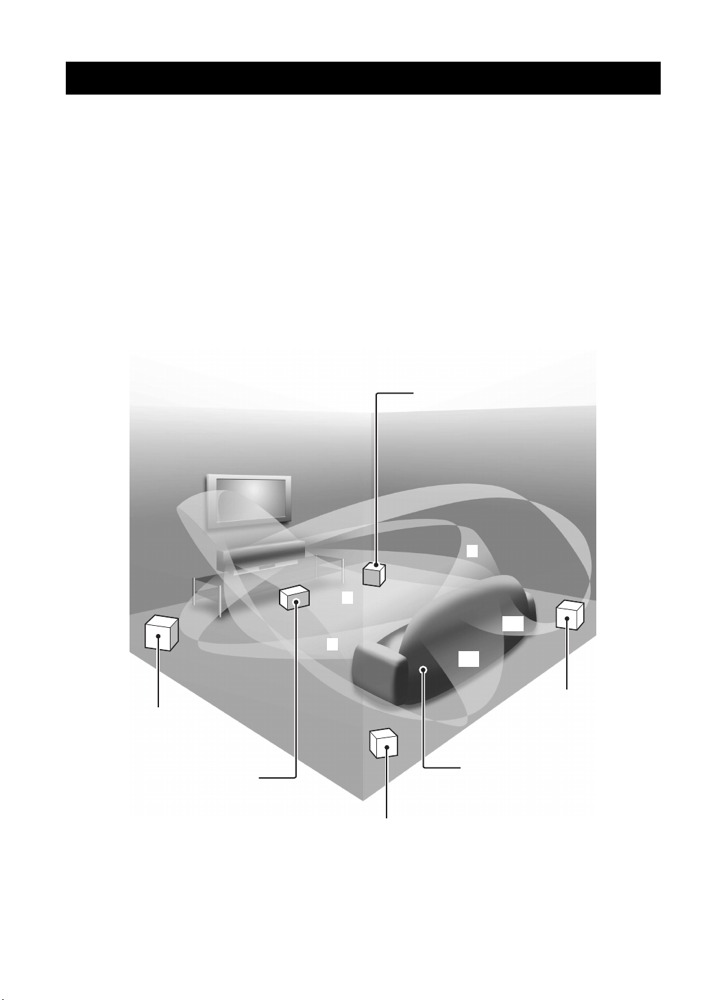
It is generally accepted that in order to fully enjoy the benefits of surround sound at home, you must endure the agony of
wiring and installing a great number of speakers in the hope that your listening room will give you the same kind of
surround sound experience as your local movie theater.
Yamaha YSP-3000 Digital Sound Projector challenges this preconception that complicated speaker setup and
troublesome wiring go hand-in-hand with the enjoyment of multi-channel surround sound.
This slimline unit does away with the need for complicated wiring and installation worries, leaving you with a unit that is
not only easy to set up, but is also capable of reproducing the kind of powerful surround sound you have been waiting for
from its built-in 2 woofers and 21 full-range small speakers.
You can fine-tune the parameters of this unit to adjust the delay time for separate sound beams, resulting in highly
directional sound that comes in on the listening position from all directions.
The YSP-3000 projects sound beams containing surround sound information for the front right (R), front left (L),
surround right (SR), and surround left (SL) speaker positions, which are reflected off the walls of your listening room
before reaching the actual listening position. With the addition of center (C) sound beams, this Digital Sound Projector
creates true-to-life 5.1-channel surround sound that makes you feel as if there are actual speakers around the room.
Sit back and enjoy the real sound experience of this simple, yet stylish Digital Sound Projector.
Imaginary
front right
speaker
Imaginary
front left
speaker
Imaginary
center
speaker
R
C
SR
L
SL
Imaginary
surround right
speaker
Listening position
Imaginary
surround left
speaker
2 En
Page 5

Features
Features
Digital Sound Projector™
The Digital Sound Projector technology allows one slim
unit to control and steer multiple channels of sound to
generate multi-channel surround sound, thus eliminates
the need for satellite loudspeakers and cabling normally
associated with conventional surround sound systems.
This unit also employs the beam modes that let you enjoy
the surround sound (5 Beam, Stereo plus 3 Beam, 3 Beam,
and My Surround), 2-channel and 5-channel stereo
playback, and My Beam.
My Surround
In addition to the above mentioned beam modes, this unit
is equipped with My Surround beam mode that allows you
to enjoy surround system even in a small listening area.
My Beam
This unit employs My Beam that ensures a clear sound in
a noisy environment. You can adjust the beam angle
manually or automatically using the supplied remote
control to the maximum of 45°, rightward and leftward.
Cinema DSP
This unit employs the Cinema DSP technology developed
by Yamaha Electronics Corp. that lets you experience
movies at home with all the original dramatic sound
impact.
HDMI™ (High-Definition Multimedia Interface)
◆ HDMI interface for standard, enhanced, or high-definition
video (including 1080p video signal transmission) as well as
multi-channel digital audio based on HDCP
◆ Simple and easy connections with HDMI supported external
components
◆ Functional link with an HDMI control-compatible TV
Versatile Remote Control
The supplied remote control comes with preset remote
control codes used to control the DVD player, VCR, cable
TV tuner, and digital satellite tuner connected to this unit.
In addition, the remote control is equipped with the macro
capability that enables a series of operations with the press
of a single button.
AUTO SETUP (IntelliBeam)
This unit employs the automatic sound beam and acoustic
optimization technology with the aid of the supplied
IntelliBeam microphone. You can avoid troublesome
listening-based speaker setup and achieve highly accurate
sound beam adjustments that best match your listening
environment.
Compatibility with the Newest Technologies
This unit employs decoders compatible with Dolby
Digital, DTS, Dolby Pro Logic, Dolby Pro Logic II, DTS
Neo:6, Music Enhancer, and Neural Surround.
◆ Dolby Digital
This is the standard audio signal format used on various
digital media such as DVD, Blu-Ray, and HD DVD. This
surround technology delivers high-quality digital audio for up
to 5.1 discrete channels to produce a directional and more
realistic effect.
◆ DTS
This is the standard audio signal format used on various
digital media such as DVD, Blu-Ray, and HD DVD. This
surround technology delivers high-quality digital audio for up
to 5.1 discrete channels to produce a directional and more
realistic effect.
◆ Dolby Pro Logic
This sophisticated, matrix decoding technology up-converts
any 2-channel source audio to a 5.1-channel full bandwidth
playback, resulting in a surround sound experience.
◆ Dolby Pro Logic II
This is a redesigned version of Dolby Pro Logic that employs
2 stereo surround channels, a subwoofer, and a greatly
enhanced steering logic. This improved technology provides
an exceptionally stable sound field that simulates 5.1 to a
much greater degree than the original Dolby Pro Logic.
◆ DTS Neo:6
This technology decodes the conventional 2-channel sources
for 6-channel playback, enabling playback with the full-range
channels with higher separation. Music mode and Cinema
mode are available to play back music and movie sources
respectively.
◆ Music Enhancer to restore the original depth and width of
compression artifacts such as the MP3 format.
◆ Neural Surround decoder (U.S.A and Canada models only)
Sophisticated FM tuner
◆ 40-station random and direct preset tuning
◆ Automatic preset tuning
◆ Radio Data System capability (Europe model only)
XM™ Satellite Radio
(U.S.A. and Canada models only)
◆ XM Satellite Radio tuning capability (using the XM MiniTuner Dock, and Antenna sold separately by XM Satellite
Radio)
◆ Neural Surround decoder to play back the XM HD content of
XM Satellite Radio broadcasts in multi-channels, resulting in
a full surround sound experience
◆ XM Satellite Radio information displaying capability
iPod™ Controlling Capability
(U.S.A., Canada, and Australia models only)
◆ DOCK terminal to connect a Yamaha iPod universal dock
(such as the YDS-10, sold separately), which supports iPod
(Click and Wheel), iPod nano, and iPod mini
◆ Playback information displaying capability
◆ Battery charging capability
INTRODUCTION
English
3 En
Page 6
Features
The “ ” logo and “IntelliBeam” are trademarks of
YAMAHA Corporation.
The “ ” logo and “Cinema DSP” are registered
trademarks of YAMAHA Corporation.
Manufactured under license from Dolby Laboratories.
“Dolby”, “Pro Logic”, and the double-D symbol are trademarks
of Dolby Laboratories.
“DTS” and “Neo:6” are registered trademarks of DTS, Inc.
“HDMI”, the “HDMI” logo and “High-Definition Multimedia
Interface” are trademarks or registered trademarks of HDMI
Licensing LLC.
Manufactured under license from 1 Ltd. Worldwide patents
applied for.
The “ ” logo and “Digital Sound Projector
™
” are trademarks
of 1 Ltd.
TruBass, SRS and the “ ” symbol are registered trademarks
of SRS Labs, Inc. TruBass technology is incorporated under
license from SRS Labs, Inc.
™
is a trademark of DiMAGIC Co., Ltd.
4 En
Page 7

Using this manual
Using this manual
Notes
• This manual describes how to connect and operate this unit. For details regarding the operation of external components, refer to the
supplied owner’s manual for each component.
• Operations in this manual use keys on the supplied remote control of this unit unless otherwise specified.
• y indicates a tip for your operation.
• This manual is printed prior to production. Designs and specifications are subject to change in part as a result of improvements, etc. In
case of differences between the manual and the product, the product has priority.
1 Install this unit in your listening room.
See “Installation” on page 16.
2 Connect this unit to your TV and other external components.
See “Connections” on page 19.
3 Prepare the remote control and turn on the power of this unit.
See “Getting started” on page 30.
INTRODUCTION
4 Run AUTO SETUP.
See “AUTO SETUP (IntelliBeam)” on page 35.
5 Play back a source.
See “Playback” on page 45.
6 Change the beam modes and/or CINEMA DSP settings.
See “Enjoying surround sound” on page 54.
If you want to make additional settings
and adjustments
7 Run MANUAL SETUP to fine-tune settings and/or set remote control codes.
See “MANUAL SETUP” on page 72 and “Remote control features” on page 96.
English
5 En
Page 8
Supplied accessories
Supplied accessories
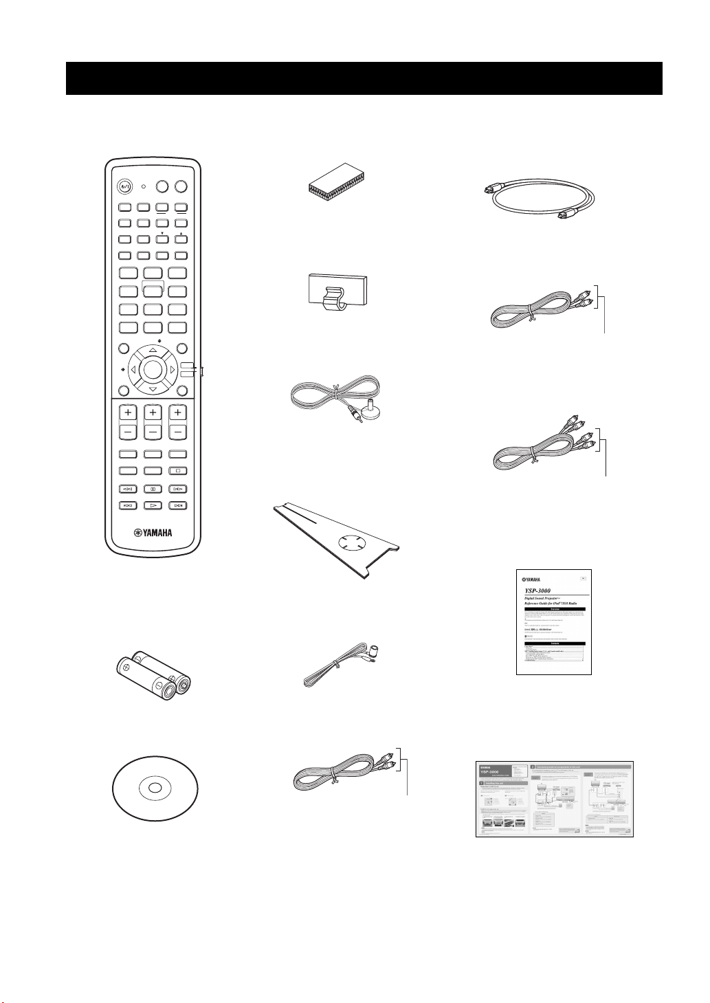
Check that you have received all of the following parts.
Remote control (×1)
POWERPOWERSTANDBY/ON
AV
TV
AUX1 AUX2
INPUT1
TV
PRESET/TUNE
CATFM/XM
AUTO
SETUP
INPUTMODE
MY BEAM
5
+10
ENTRY
ENTER
CH
TV INPUT TV MUTE
DOCK
AUX3
TV
MACRO
MEMORYSEARCH
SLEEP
321
6
SPORTS
9
SUR. DECODE
RETURNDISPLAY
TV VOL
CODE SET
TV/AV
YSP
DVD
STB
VOL MODE
5BEAM ST+3BEAM 3BEAM
STEREO MY SUR.
4
MUSIC MOVIE
78
OFF
0
ENHANCER MENU
CAT/
A-E
VOLUME
MUTE
CH LEVEL TEST
(U.S.A. and Canada models)
Fasteners (×4)
Cable clamp (×1)
IntelliBeam microphone
(×1)
Cardboard microphone
stand (×1)
Optical cable (×1)
Digital audio pin cable (×1)
(Orange)
Audio pin cable (×1)
(White/Red)
REFERENCE GUIDE
(iPod/XM Radio) (×1)
Demonstration DVD
6 En
Batteries (×2)
(AA, R6, UM-3)
(×1)
Indoor FM antenna (×1)
OSD* video pin cable (×1)
(Yellow)
*OSD: On-Screen Display
(U.S.A., Canada, and Australia
models only)
QUICK REFERENCE
GUIDE
* The number of provided languages
varies depending on the model.
Page 9
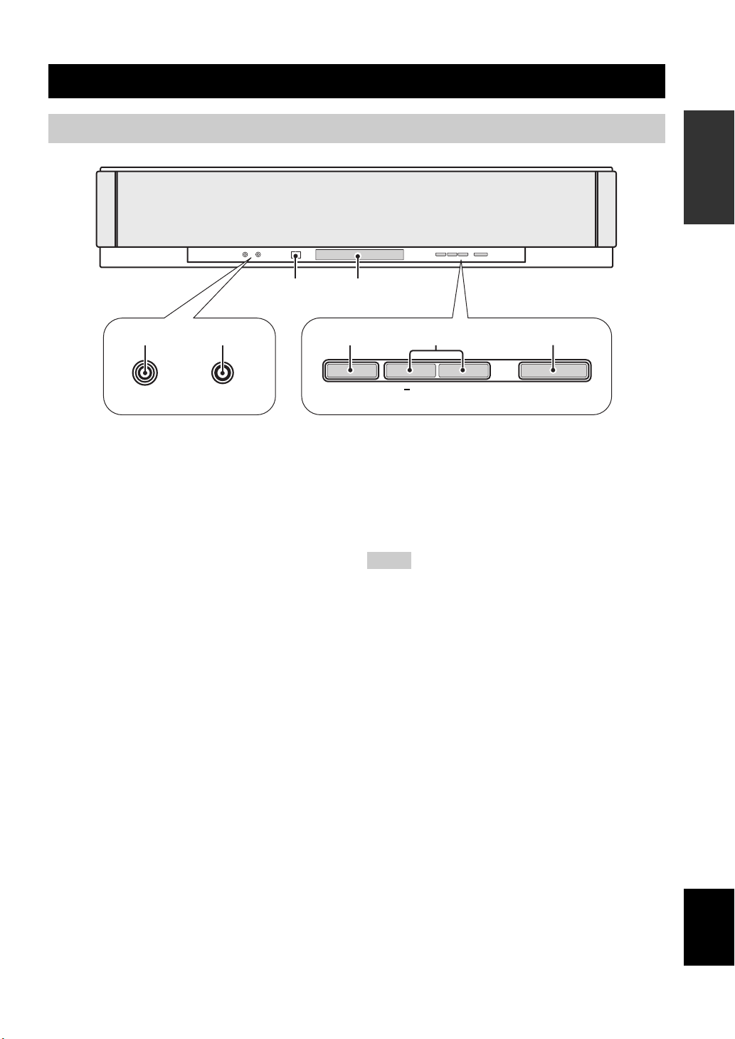
Front panel
Controls and functions
Controls and functions
INTRODUCTION
3 4
21
AUX 3
INTELLIBEAM MIC
1 AUX 3 input jack
Connect your portable audio player (see page 26).
2 INTELLIBEAM MIC jack
Connect the supplied IntelliBeam microphone for AUTO
SETUP (see page 36).
3 Remote control sensor
Receives infrared signals from the remote control.
4 Front panel display
Shows information about the operational status of this
unit.
5 INPUT
Press repeatedly to switch between input sources (see
page 45).
Outputs a test tone to experience the sound beam (see
page 91).
5
INPUT
6
VOLUME
+
7
STANDBY/ON
6 VOLUME +/–
Controls the volume level of all audio channels (see
page 47).
7 STANDBY/ON
Turns on the power of this unit or sets it to the standby
mode (see page 31).
Notes
• When you turn on this unit, you will hear a click sound
followed by the 4 to 5-second interval before sound
reproducing.
• In the standby mode, this unit consumes a small amount of
power in order to receive infrared signals from the remote
control or to search for HDMI signals.
7 En
English
Page 10
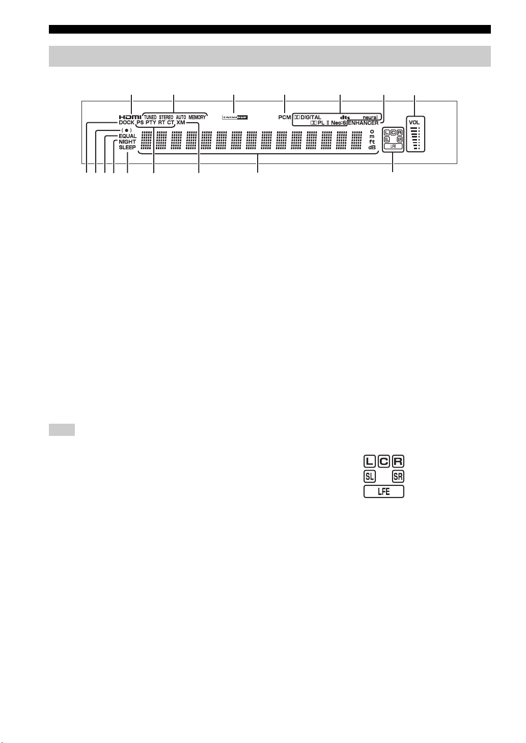
Controls and functions
Front panel display
1
0
89
AB C D
1 HDMI indicator
Lights up when the signal of the selected input source is
input at the HDMI IN jack(s).
2 TUNER indicators
FM: Light up when this unit is receiving an FM broadcast.
XM: MEMORY flashes during the XM preset operation
(U.S.A. and Canada models only).
3 CINEMA DSP indicator
Lights up when a sound field program is selected (see
page 64).
4 PCM indicator
Lights up when this unit is reproducing PCM (Pulse Code
Modulation) digital audio signals.
5 Decoder indicators
Light up when the corresponding decoder operates
(see page 56).
Note
The neural decoder is available for the U.S.A. and Canada models
only.
6 ENHANCER indicator
Lights up when the Music Enhancer is selected (see
page 66).
7 Volume level indicator
Displays the current volume level.
8 DOCK indicator
(U.S.A., Canada, and Australia models only)
Lights up when your iPod (Click and Wheel), iPod nano,
or iPod mini is connected to this unit via the DOCK
terminal on this unit.
23
EF
4
A NIGHT indicator
Lights up when one of the night listening enhancers is
selected (see page 67).
B SLEEP indicator
Lights up when the sleep timer is set (see page 68).
C Radio Data System indicators
(Europe model only)
Show the current Radio Data System status.
D XM indicator
(U.S.A. and Canada models only)
Lights up when XM is selected as the input source.
E Multi-information display
Shows information with alphanumeric characters when
you adjust the parameters of this unit.
F Input channel indicators
Show information when you adjust the parameters of this
unit. The channel component of the current digital input
signal is displayed (see page 56).
y
You can adjust the brightness and display setting of the front
panel display using the F.DISPLAY SET parameter in MANUAL
SETUP (see page 83).
5
67
9 SRS TruBass indicator
Lights up when TruBass is turned on (see page 79).
0 EQUAL indicator
Lights up when the TV volume equal mode is selected
(see page 67).
8 En
Page 11
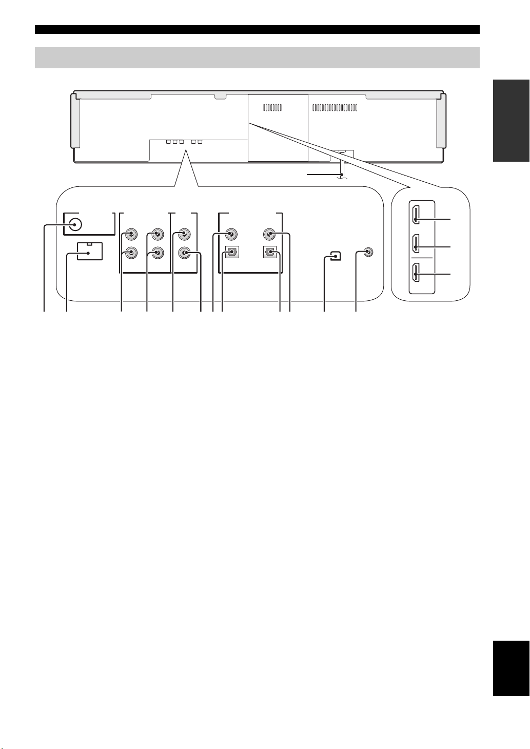
Rear panel
2
Controls and functions
The illustration below shows the rear panel of the U.S.A. and Canada models.
F
1
DOCK
AUDIO INPUTANTENNA
AUX 1 AUX 1
3
4
TV/STB
VIDEO
SUBWOOFER
5
6
1 ANTENNA jack
Connect the FM antenna (see page 29).
2 DOCK terminal
(U.S.A., Canada, and Australia models only)
Connect the Yamaha iPod universal dock (such as YDS10, sold separately) (see page 2 in the Reference Guide).
3 AUX 1 AUDIO INPUT jacks
Connect an external component via an analog connection
(see page 23).
4 TV/STB AUDIO INPUT jacks
Connect your TV, digital satellite tuner, or cable TV tuner
via an analog connection (see pages 22 and 24).
5 VIDEO OUT jack
Connect to the video input jack of your TV to display the
OSD of this unit (see page 22).
6 SUBWOOFER OUT jack
Connect your subwoofer (see page 28).
7 AUX 2 COAXIAL DIGITAL INPUT jack
Connect an external component via a coaxial digital
connection (see page 27).
8 AUX 1 OPTICAL DIGITAL INPUT jack
Connect an external component via an optical digital
connection (see page 27).
7
8
DIGITAL INPUTOUT
AUX 2
DVD
COAXIAL
OPTICAL
TV/STB
90
0 DVD COAXIAL DIGITAL INPUT jack
Connect your DVD player via a coaxial digital connection
(see page 23).
A XM antenna jack
(U.S.A and Canada models only)
Connect your XM Mini-Tuner Dock (sold separately)
(see page 5 in the Reference Guide).
B IR IN terminal
(U.S.A and Canada models only)
This is a control expansion terminal for commercial use
only (see page 29).
C AUX 1 HDMI IN jack
Connect your digital satellite tuner, cable TV tuner, digital
air wave tuner, or game console via an HDMI connection
(see page 21).
D DVD HDMI IN jack
Connect your DVD player via an HDMI connection (see
page 21).
E HDMI OUT jack
Connect to the HDMI IN jack on your HDMI component
such as a TV or a projector connected to this unit (see
page 21).
F AC power supply cable
Connect to the AC wall outlet (see page 29).
9 TV/STB OPTICAL DIGITAL INPUT jack
Connect your TV, digital satellite tuner, or cable TV tuner
via an optical digital connection (see pages 22 and 24).
A
AUX 1
DVD
IN
IR INXM
OUT
HDMI
B
(U.S.A. and Canada models)
INTRODUCTION
C
D
E
English
9 En
Page 12
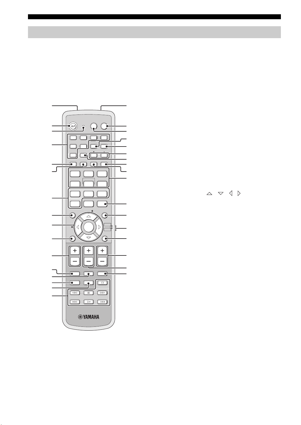
Controls and functions
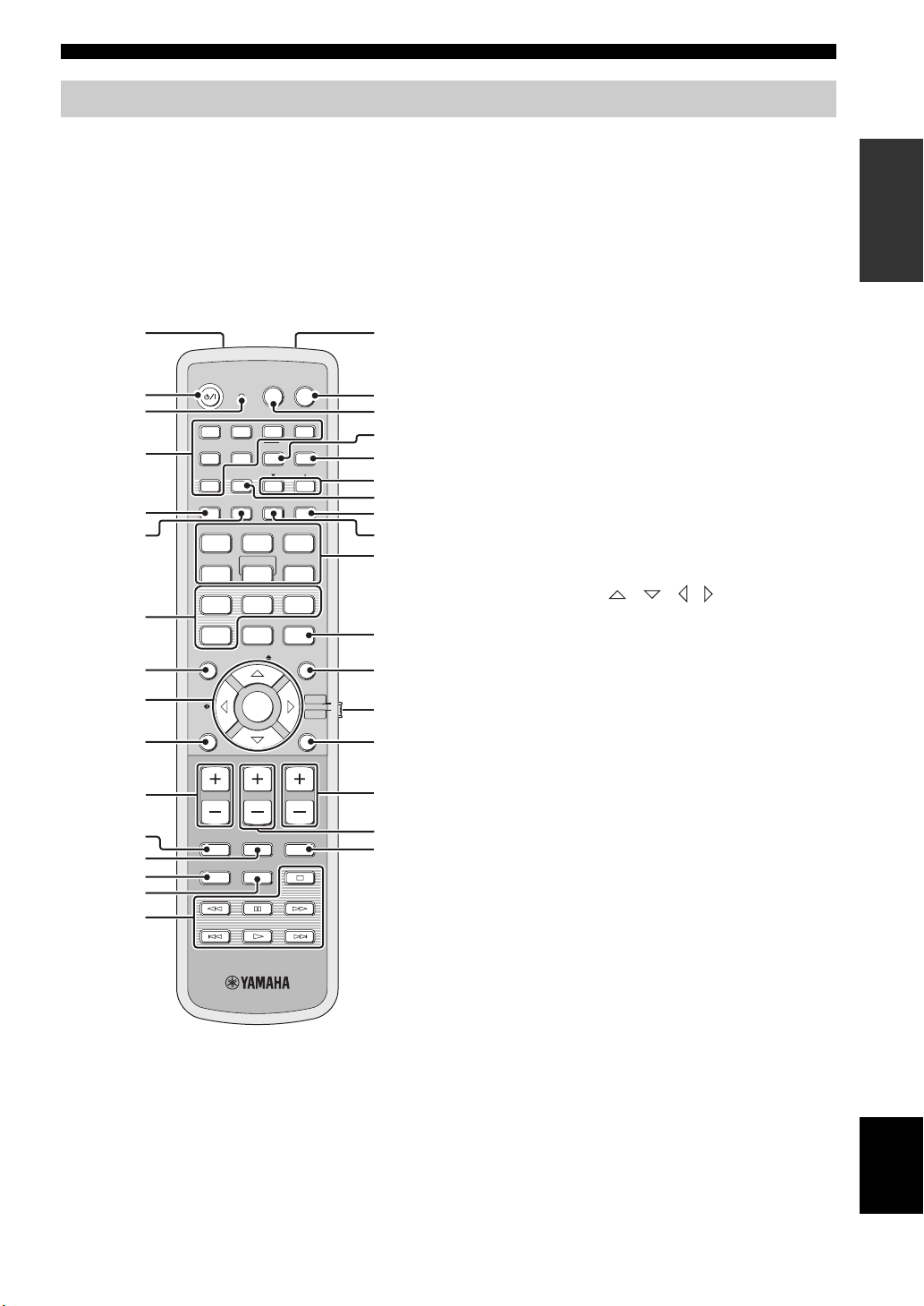
Remote control (Europe, Australia, Asia, and Korea models)
This section describes the functions of the remote control
used to control this unit. Some buttons marked with an
asterisk (*) share the common functions between the YSP
and TV/AV operation modes (S).
y
You can also control other components using the remote control
once you set the appropriate remote control codes. See
“Controlling other components” on page 97 for details.
1G
POWERPOWERSTANDBY/ON
INPUT1
INPUTMODE
5
CH
TVAV
AUX3
TV
MACRO
MEMORYSEARCH
SLEEP
321
MY SUR.
6
SPORTS
9
SUR. DECODE
TV/AV
RETURNDISPLAY
TV VOL
CODE SET
YSP
H
I
J
K
L
M
N
O
P
Q
R
S
t
U
V
W
*
*
*
*
*
*
2
*
3
DVD
AUX1 AUX2
4
*
5
6
7
TV
STB
PRESET/TUNE
A-E
FM
AUTO
SETUP
VOL MODE
5BEAM ST+3BEAM 3BEAM
STEREO
MY BEAM
4
MUSIC MOVIE
78
OFF
+10
0
ENHANCER MENU
ENTRY
8
9
A-E
ENTER
0
VOLUME
A
*
MUTE
B
*
C
*
D
TV INPUT TV MUTE
CH LEVEL TEST
E
F
1 Infrared window
Outputs infrared control signals. Aim this window at the
component you want to operate.
2 STANDBY/ON
Sets this system to the standby mode (see page 31).
3 Transmission indicator
Lights up when infrared control signals are being output.
4 Input selector buttons
Use to select an input source (DVD, AUX1, AUX2,
AUX3, STB, TV, or FM).
5 VOL MODE
Turns on or off the volume modes (see page 67).
6 AUTO SETUP
Enters the AUTO SETUP menu (see page 35).
7 CINEMA DSP program buttons
Select the CINEMA DSP programs (see page 63).
8 ENHANCER
Turns on or off the Music Enhancer (see page 66).
9 Cursor buttons / / / , ENTER
Select and adjust SET MENU items.
0 DISPLAY
Displays information on the selected input signal.
A VOLUME +/–
Increases or decreases the volume level of this unit (see
page 47).
B MUTE
Mutes the sound. Press again to restore the audio output to
the previous volume level (see page 47).
C TV INPUT
Toggles between the input sources on the TV (see
page 97).
D CH LEVEL
Adjusts the volume level of each channel (see page 85).
E TEST
Outputs a test tone when adjusting the output level of each
channel (see page 84).
10 En
Page 13

Controls and functions
F DVD player/VCR control buttons
Control your DVD player or VCR (see pages 98 and 99).
G My Beam microphone
Collects the test tones from this unit when using the My
Beam auto-adjust function (see page 61).
H TV POWER
Turns on the power of your TV or sets it to the standby
mode (see page 97).
I AV POWER
Turns on the power of the selected component or sets it to
the standby mode (see pages 98 and 99).
J INPUT1
Switches the input source on your TV (see page 97).
K MACRO
Use to set the TV macro (see page 100).
L a /5
Switches the preset station number (1 to 8) when this unit
is receiving an FM broadcast (see page 52).
M A-E
Switches the preset station group (A to E) when this unit is
receiving an FM broadcast (see page 52).
N SLEEP
Sets the sleep timer (see page 68).
O INPUTMODE
Toggles between input modes (AUTO, DTS, and
ANALOG) (see page 87).
P Beam mode buttons
Change the beam mode settings (see pages 54, 60, and
61).
Q SUR. DECODE
Selects the surround mode for playback (see page 57).
R MENU
Displays the setup menu on your TV monitor (see
pages 37 and 73).
S Operation mode selector
Selects the operation mode of this unit. Select YSP when
operating this unit and select TV/AV when operating your
TV or other AV components.
T RETURN
Selects sleep timer settings or returns to the previous SET
MENU screen.
U TV VOL +/–
Adjusts the volume level of your TV (see page 97).
V CH +/–
Changes the channels of your TV, digital satellite tuner,
cable TV tuner, or VCR (see pages 97 and 99).
W TV MUTE, CODE SET
Mutes the audio output of your TV (see page 97).
Sets up remote control codes (see page 96).
Note
The functions L and M are available only when the FM stations
are preset.
INTRODUCTION
11 En
English
Page 14
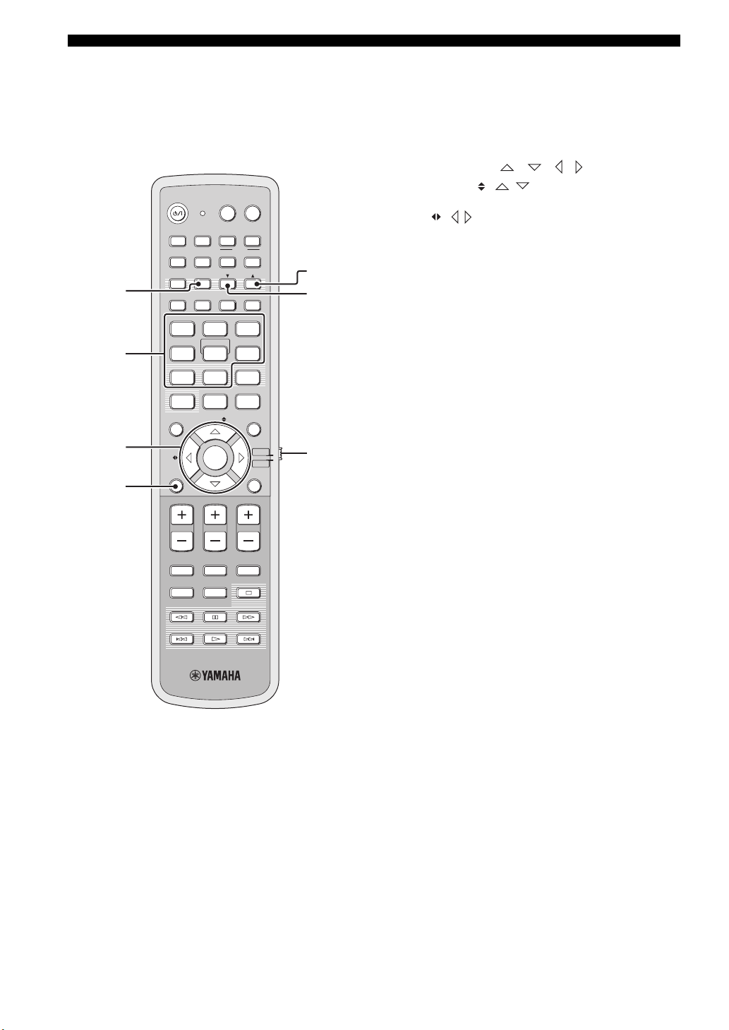
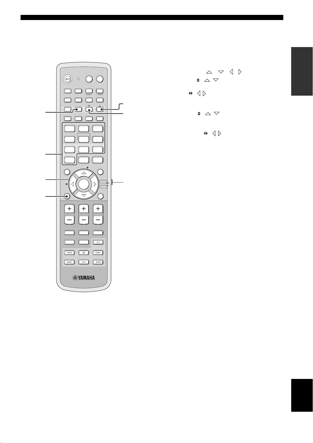
Controls and functions
This section describes the functions of the remote control
used to control FM, Radio Data System, or iPod when the
TV/AV mode is selected with the operation mode selector
(7). Note that the Radio Data System controls are
available for Europe model only, and the iPod controls are
available for Australia model only.
POWERPOWERSTANDBY/ON
TVAV
DVD
1
2
3
AUX1 AUX2
TV
STB
PRESET/TUNE
A-E
FM
AUTO
SETUP
VOL MODE
5BEAM ST+3BEAM 3BEAM
STEREO
MY BEAM
4
MUSIC MOVIE
78
OFF
0
ENHANCER MENU
A-E
INPUTMODE
5
+10
ENTRY
ENTER
INPUT1
AUX3
TV
MACRO
MEMORYSEARCH
SLEEP
321
MY SUR.
6
SPORTS
9
SUR. DECODE
TV/AV
YSP
RETURNDISPLAY
5
6
7
4
VOLUME
MUTE
CH LEVEL TEST
TV VOL
CH
TV INPUT TV MUTE
CODE SET
1 PRESET/TUNE
FM: Switches between the preset search mode and the
frequency search mode (see pages 49 to 52).
2 Numeric buttons
FM: Enter numbers.
3 Cursor buttons / / / / ENTER
FM: Use ENTRY ( / ) to change the preset station
number (1 to 8) or frequency level (see pages 49 to 52).
Use A-E ( / ) to change the preset station group (A to
E) (see pages 51 and 52). Use ENTER to confirm the input
above.
y
These functions are also available when this unit is receiving the
Radio Data System (see page 52) or playing back your iPod (see
page 3 in the Reference Guide).
4 DISPLAY
Radio Data System and iPod: Displays information when
this unit is receiving the Radio Data System (see page 52)
or playing back your iPod (see page 3 in the Reference
Guide).
5 MEMORY
FM: Stores the preset stations (see pages 50 and 51).
y
This function is also available when this unit is receiving the
Radio Data System (see page 52).
6 SEARCH
FM: Switches between automatic and manual tuning (see
page 49).
7 Operation mode selector
Selects the operation mode of this unit. Select YSP when
operating this unit and select TV/AV when operating your
TV or other AV components.
12 En
Page 15
Remote control (U.S.A. and Canada models)
Controls and functions
This section describes the functions of the remote control
used to control this unit. Some buttons marked with an
asterisk (*) share the common functions between the YSP
and TV/AV operation modes (S).
y
You can also control other components using the remote control
once you set the appropriate remote control codes. See
“Controlling other components” on page 97 for details.
1G
POWERPOWERSTANDBY/ON
2
*
3
DVD
4
*
5
6
7
STB
VOL MODE
5BEAM ST+3BEAM
STEREO
4
MUSIC MOVIE
78
OFF
0
ENHANCER MENU
8
9
CAT/
A-E
0
VOLUME
A
*
B
*
C
*
D
MUTE
CH LEVEL TEST
AV
AUX1 AUX2
INPUT1
TV
PRESET/TUNE
CATFM/XM
AUTO
SETUP
INPUTMODE
MY BEAM
5
+10
ENTRY
ENTER
CH
TV INPUT TV MUTE
TV
DOCK
AUX3
TV
MACRO
MEMORYSEARCH
SLEEP
3BEAM
321
MY SUR.
6
SPORTS
9
SUR. DECODE
TV/AV
RETURNDISPLAY
TV VOL
CODE SET
YSP
H
I
J
K
L
M
N
O
P
Q
R
S
t
U
V
W
*
*
*
*
*
*
E
F
1 Infrared window
Outputs infrared control signals. Aim this window at the
component you want to operate.
2 STANDBY/ON
Sets this system to the standby mode (see page 31).
3 Transmission indicator
Lights up when infrared control signals are being output.
4 Input selector buttons
Use to select an input source (DVD, AUX1, AUX2,
AUX3/DOCK, STB, TV, or FM/XM).
5 VOL MODE
Turns on or off the volume modes (see page 67).
6 AUTO SETUP
Enters the AUTO SETUP menu (see page 35).
7 Sound field program buttons
Select the sound field programs (see page 63).
8 ENHANCER
Turns on or off the Music Enhancer (see page 66).
9 Cursor buttons / / / , ENTER
Select and adjust SET MENU items.
0 DISPLAY
Displays information on the selected input signal.
A VOLUME +/–
Increases or decreases the volume level of this unit (see
page 47).
B MUTE
Mutes the sound. Press again to restore the audio output to
the previous volume level (see page 47).
C TV INPUT
Toggles between the input source on your TV (see
page 97).
D CH LEVEL
Adjusts the volume level of each channel (see page 85).
E TEST
Outputs a test tone when adjusting the output level of each
channel (see page 84).
INTRODUCTION
13 En
English
Page 16

Controls and functions
F DVD player/VCR control buttons
Control your DVD player or VCR (see pages 98 and 99).
G My Beam microphone
Collects the test tones from this unit when using the My
Beam auto-adjust function (see page 61).
H TV POWER
Turns on the power of your TV or sets it to the standby
mode (see page 97).
I AV POWER
Turns on the power of the selected component or sets it to
the standby mode (see pages 98 and 99).
J INPUT1
Switches the input source on your TV (see page 97).
K MACRO
Use to set the TV macro (see page 100).
L a /5
Switches the preset station number (1 to 8) when this unit
is receiving an FM broadcast or XM channel (see
page 52).
M CAT
Switches the preset station group (A to E) when this unit is
receiving an FM broadcast or XM channel (see page 52).
N SLEEP
Sets the sleep timer (see page 68).
T RETURN
Selects sleep timer settings or returns to the previous SET
MENU screen.
U TV VOL +/–
Adjusts the volume level of your TV (see page 97).
V CH +/–
Changes the channels of your TV, digital satellite tuner,
cable TV tuner, or VCR (see pages 97 and 99).
W TV MUTE, CODE SET
Mutes the audio output of your TV (see page 97).
Sets up remote control codes (see page 96).
Note
The functions L and M are available only when the FM/XM
stations are preset.
O INPUTMODE
Toggles between input modes (AUTO, DTS, and
ANALOG) (see page 87).
P Beam mode buttons
Change the beam mode settings (see pages 54, 60, and
61).
Q SUR. DECODE
Selects the surround mode for playback (see page 57).
R MENU
Displays the setup menu on your TV monitor (see
pages 37 and 73).
S Operation mode selector
Selects the operation mode of this unit. Select YSP when
operating this unit and select TV/AV when operating your
TV or other AV components.
14 En
Page 17
Controls and functions
This section describes the functions of the remote control
used to control FM, XM Satellite Radio, or iPod when the
TV/AV mode is selected with the operation mode selector
(7).
POWERPOWERSTANDBY/ON
AV
TV
1
2
3
AUX1 AUX2
DVD
TV
STB
PRESET/TUNE
CATFM/XM
AUTO
SETUP
VOL MODE
5BEAM ST+3BEAM 3BEAM
STEREO
4
MUSIC MOVIE
78
OFF
0
ENHANCER MENU
CAT/
A-E
INPUTMODE
MY BEAM
5
+10
ENTRY
ENTER
INPUT1
DOCK
AUX3
TV
MACRO
MEMORYSEARCH
SLEEP
321
MY SUR.
6
SPORTS
9
SUR. DECODE
TV/AV
RETURNDISPLAY
YSP
5
6
7
4
VOLUME
MUTE
CH LEVEL TEST
TV VOL
CH
TV INPUT TV MUTE
CODE SET
1 PRESET/TUNE
FM: Switches between the preset search mode and the
frequency search mode (see pages 49 to 52).
2 Numeric buttons
FM, XM: Enter numbers.
3 Cursor buttons / / /
FM: Use ENTRY ( / ) to change the preset station
number (1 to 8) or frequency level (see pages 49 to 52).
Use CAT/A-E ( / ) to change the preset station group
(A to E) (see pages 51 and 52). Use ENTER to confirm the
input above.
XM: Use ENTRY ( / ) to select XM channels in
All Channel Search mode/Category Search mode, and to
select the preset channel number (1 to 8) in Preset Search
mode. Use CAT/A-E ( / ) to select XM categories in
All Channel Search mode/Category Search mode, and to
select the preset channel group (A to E) in Preset Search
mode. Use ENTER to confirm the input above (see pages
7 and 8 in the Reference Guide).
y
These functions are also available when this unit is playing back
your iPod (see page 3 in the Reference Guide).
4 DISPLAY
XM and iPod: Displays information when this unit is
receiving an XM channel (see page 10 in the Reference
Guide) or playing back your iPod (see page 3 in the
Reference Guide).
5 MEMORY
FM: Stores the preset stations (see pages 50 and 51).
XM: Use to store the preset stations (see page 9 in the
Reference Guide).
6 SEARCH
FM: Switches between automatic and manual tuning (see
page 49).
XM: Switches between search modes (All Channel
Search, Category Search, and Preset Search) (see pages 7
and 8 in the Reference Guide).
7 Operation mode selector
Selects the operation mode of this unit. Select YSP when
operating this unit and select TV/AV when operating your
TV or other AV components.
INTRODUCTION
15 En
English
Page 18
Installation
Installation
This section describes a suitable installation location to install this unit using a metal wall bracket, a rack or a stand.
Depending on your installation environment, connections with external components can be done before installing this
unit. We recommend that you temporarily place and arrange all components, including this unit, in order to decide which
procedure should come first. Especially when you make a connection over HDMI, we recommend that you make a
connection first before installation (see page 21).
Before installing this unit
This unit creates surround sound by reflecting projected
sound beams off the walls of your listening room. The
surround sound effects produced by this unit may not be
sufficient when this unit is installed in the following
locations.
• Rooms with walls inadequate for reflecting sound
beams
• Rooms with acoustically absorbent walls
• Rooms with measurements outside the following
range: W (3 to 7 m (10 to 23 ft)) x H (2 to 3.5 m (7 to
11.5 ft)) x D (3 to 7 m (10 to 23 ft))
• Rooms with less than 1.8 m (6 ft) from the listening
position to this unit
• Rooms where objects such as furniture are likely to
obstruct the path of sound beams
• Rooms where the listening position is close to the walls
• Rooms where the listening position is not in front of
this unit
y
• You can enjoy surround sound by selecting My Surround (see
page 55) as the beam mode even if your listening room may not
fulfill the above conditions (except when the listening position
is not directly facing toward the front of this unit).
• You can also enjoy surround sound by selecting 2-channel or 5-
channel stereo playback (see page 60) or My Beam (see
page 61) as the beam mode even if your listening room may not
fulfill the above conditions.
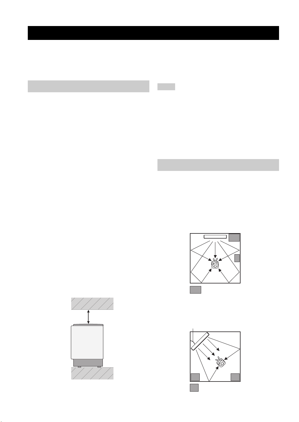
Make sure you leave an adequate amount of ventilation
space so that heat can escape. Make at least 5 cm (2 in) of
space above or below this unit.
Side view
Notes
• We do not recommend putting this unit directly on the floor of
your listening room. Please install this unit using a metal wall
bracket, a rack, or a stand.
• This unit weighs 11.5 kg (25 lbs 6 oz). Be sure to install this
unit where it will not fall subject to vibrations, such as from an
earthquake, and where it is out of the reach of children.
• When using a cathode-ray tube (CRT) TV, do not install this
unit directly above your TV.
• This unit is shielded against magnetic rays. However, if the
picture on your TV screen becomes blurred or distorted, we
recommend moving this unit away from your TV.
Installing this unit
Install this unit where there are no obstacles such as
furniture obstructing the path of sound beams. Otherwise,
the desired surround sound effects may not be achieved.
You may install this unit in parallel with the wall or in the
corner.
Parallel installation
Install this unit in the exact center of the wall when it is
measured from the left and right corners.
An object, such as furniture
16 En
Front
5 cm (2 in) or more
Rear
Corner installation
Install this unit in the corner at a 40º to 50º angle from the
adjacent walls.
40° to 50°
An object, such as furniture
Page 19
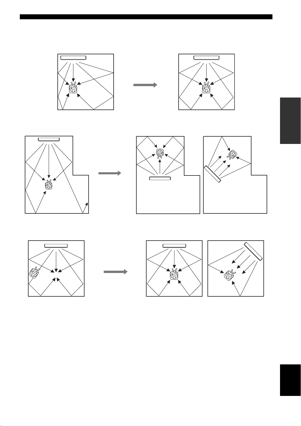
■ Installation examples
Example 1
Install this unit as close to the exact center of the wall as possible.
Example 2
Install this unit so that the sound beams can be reflected off the walls.
Installation
PREPARATION
Example 3
Install this unit as close to the exact front of your normal listening position as possible.
English
17 En
Page 20
Installation
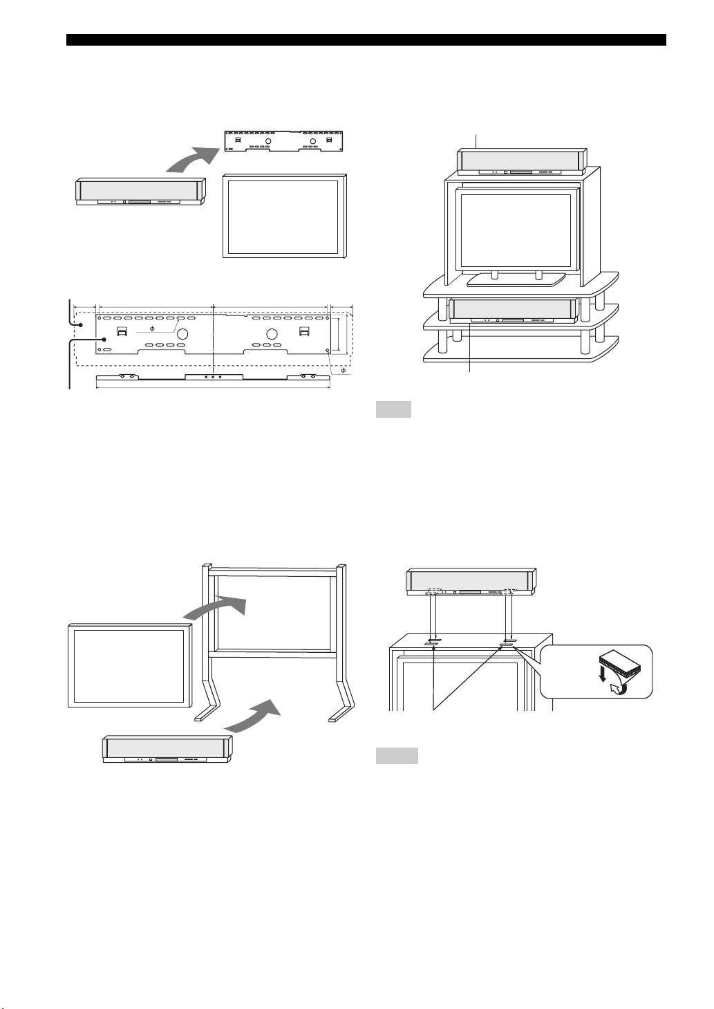
■ Using a metal wall bracket
You can use the optional metal wall bracket to mount this
unit on the wall in your listening room.
Metal wall bracket
This unit
TV
YSP-3000
65
SPM-K30 (Option)
325 65325
24- 7x22
670
92
4- 7
y
Refer to the instructions supplied with the metal bracket for
details on how to attach the metal bracket to the wall or how to
attach this unit to the metal bracket.
■ Using a stand
You can mount your TV on a stand placed on a
commercially available rack and install this unit under
your TV.
Stand
■ Using a rack
You can install this unit either above or under your TV in a
commercially available rack.
When this unit is installed above your TV
112
When this unit is installed under your TV
Note
Make sure that the rack is large enough to allow adequate
ventilation space around this unit (see page 16) and that it is
strong enough to support the weight of both this unit and your TV.
■ Affixing this unit
Peel off the film from each of the four supplied fasteners
and then secure them to the bottom four corners of this
unit and the top of the rack, etc.
This unit
TV
This unit
y
Refer to the instructions supplied with the stand for details on
how to install the stand or how to mount and the TV on the stand.
18 En
Fasteners
Peel off
the film
2
1
Notes
• Do not install this unit on top of a slanted surface. This unit may
fall over and cause injury.
• Make sure you wipe the surface of the rack, etc. before securing
the fasteners. Applying the tape to a dirty or wet surface will
weaken the sticking power of the tape, and this unit may fall as
a result.
Page 21
Connections
Connections
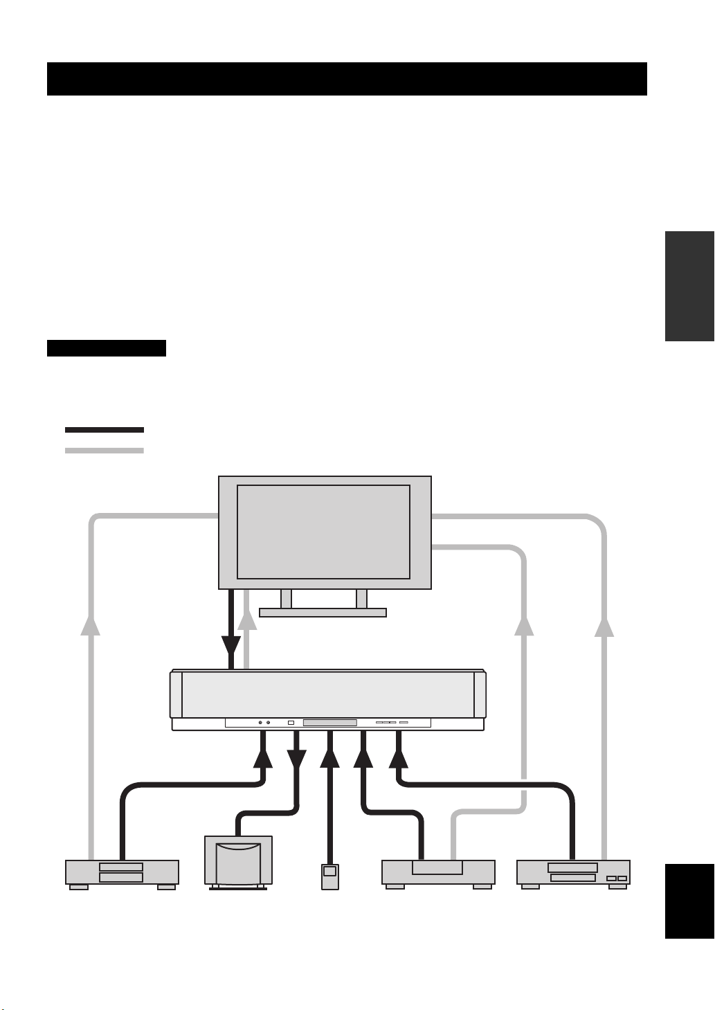
This unit is equipped with the following types of audio/video input/output jacks/terminal:
For audio input
• 2 optical digital input jacks
• 2 coaxial digital input jacks
• 2 sets of analog input jacks
• 1 universal dock terminal
(U.S.A., Canada, and Australia models only)
For audio/video input
• 2 HDMI input jacks
Use these jacks/terminal to connect external components such as your TV, DVD player, VCR, digital satellite tuner, cable
TV tuner, digital air wave tuner, portable audio player, game console, and iPod. Further, by connecting a subwoofer to
this unit, you can enjoy reinforced low-bass sounds. For details on how to connect various types of external components
to this unit, see pages 21 to 28.
CAUTION
• Do not connect this unit or other components to the mains power until all connections between components are
complete.
• Unplug the AC power supply cable before changing connections, moving or cleaning this unit.
Audio connection
Video connection
TV
For audio output
• 1 subwoofer output jack
For audio/video output
• 1 HDMI output jack
For video output
• 1 analog output jack
PREPARATION
This unit
portable audio
player
English
VCR or game consoleDVD player Subwoofer Digital satellite tuner
or cable TV tuner
19 En
Page 22
Connections
Before connecting components
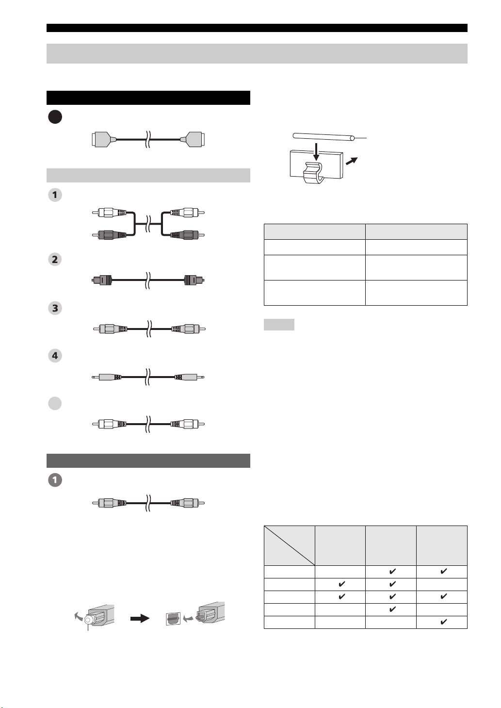
■ Cables used for connections
Audio/Video
HDMI cable
A
Audio
Audio pin cable (supplied)
(White)
(Red)
Optical cable (supplied)
Digital audio pin cable (supplied)
3.5 mm stereo mini plug cable
Subwoofer pin cable
5
(White)
(Red)
(Orange)(Orange)
■ Affixing cables
To prevent cables from becoming unplugged, place the
supplied cable clamp with the open side facing upward,
attach it to the rear panel of this unit in a suitable position,
and then affix cables in the cable clamp.
Optical cable
Attach to this unit
■ Information on HDMI™
Audio Signals
Input source Audio signal type
DVD video Dolby Digital, DTS, PCM
DVD audio
Blu-ray Disc
HD DVD
Notes
• When CPPM copy-protected DVD audio is played back, video
and audio signals may not be output depending on the type of
DVD player.
• This unit is not compatible with HDCP-incompatible HDMI or
DVI components.
y
• We recommend that you use an HDMI cable shorter than 5 m
(16 ft) with the HDMI logo printed on it.
• Use a conversion cable (HDMI jack
this unit to other DVI components.
2-channel stereo
(up to 96 kHz/24 bit)
Dolby Digital, DTS, PCM
↔ DVI-D jack) to connect
Video
OSD video pin cable (supplied)
(Yellow)(Yellow)
■ Notes on connecting the optical cable
• Pull out the cap before connecting the optical cable.
When you are not using the optical cable, be sure to put
the cap back in place.
• When inserting the cable into the optical digital jack,
make sure the direction is correct.
Cap
20 En
■ Priority order for audio input signals
When multiple types of audio signals are simultaneously
being input from a single source component, this unit
plays back the audio signals in the following priority
order: HDMI → Digital → Analog
As default settings, the following input jacks are assigned
to the corresponding input sources:
Input
Input
source
TV/STB
DVD
AUX 1
AUX 2
AUX 3
jack
HDMI Digital Analog
Page 23
Connections
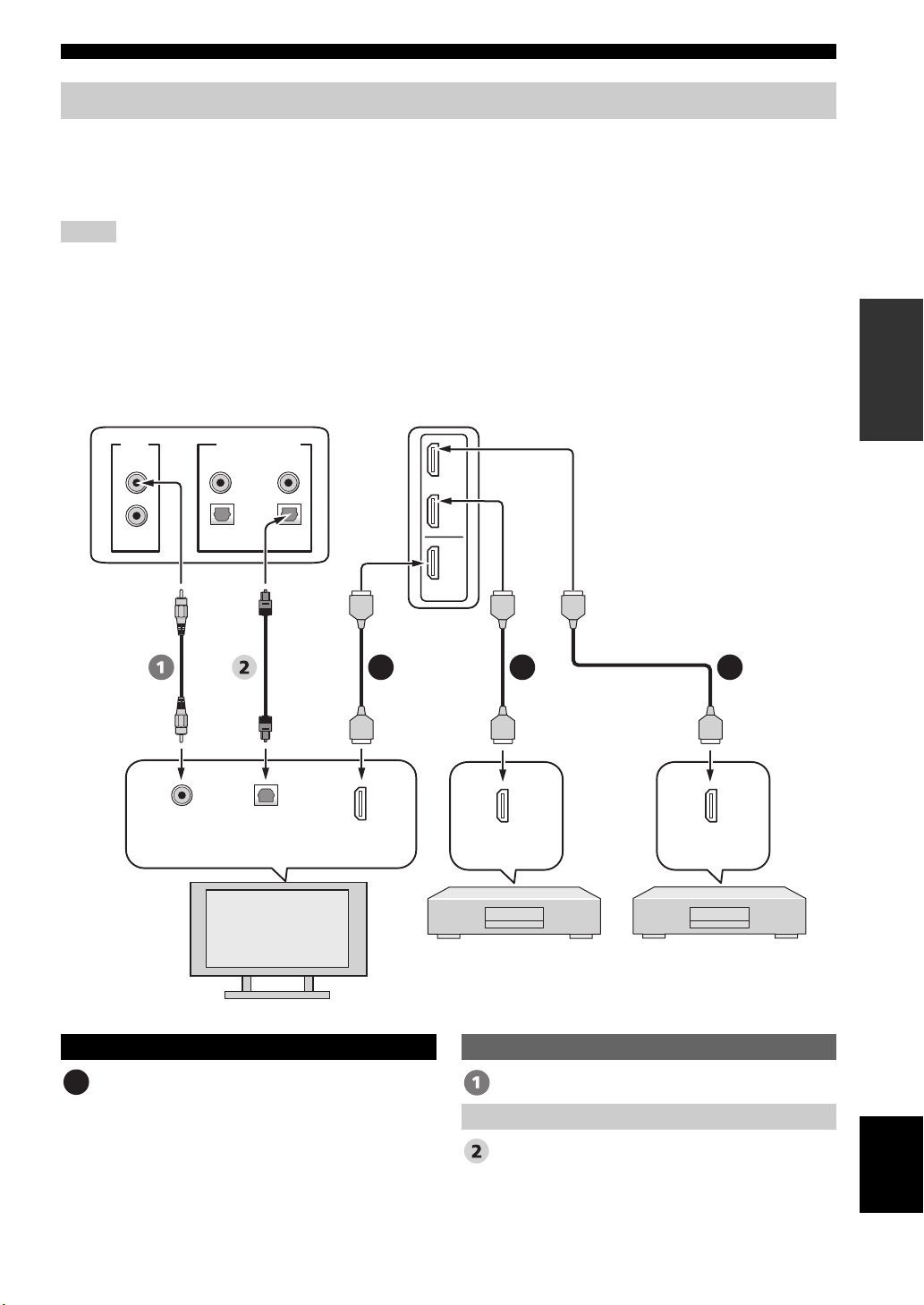
Connections using HDMI cables
This unit is equipped with 2 HDMI input jacks and 1 HDMI output jack. If your TV and other components have HDMI
jacks, use HDMI cables for simpler and easier connections, and you can skip the connection procedures from page 22 to
25. If your TV has a built-in digital satellite tuner and an optical digital output jack, connect the optical digital output jack
on your TV to the TV/STB OPTICAL DIGITAL INPUT jack on this unit.
Notes
• Even if you connect your TV and this unit via the HDMI jack, you need to connect the video input jack on your TV to the VIDEO
OUT jack on this unit in order to display the OSD of this unit.
• When HDMI CONTROL is set to OFF (see page 82) and this unit is in the standby mode, the signals input at the HDMI IN jacks are
not output at the HDMI OUT jack.
y
We recommend that you secure the HDMI cable(s) with adhesive tape, etc. once you have connected the HDMI cable(s) to the HDMI
jack(s) of this unit.
Rear panel of this unit
PREPARATION
VIDEO
SUBWOOFER
Video
input
DIGITAL INPUTOUT
AUX 2
AUX 1
COAXIAL
OPTICAL
TV/STB
Optical
digital
input
TV
DVD
AUX 1
DVD
IN
OUT
HDMI
A AA
HDMI
input
HDMI
output
DVD player/recorder
*
This connection (except for a game
console) is not necessary if your
TV has a built-in digital satellite
tuner, cable TV tuner, or digital
airwave tuner.
HDMI
output
Digital satellite tuner,
cable TV tuner,
digital airwave tuner,
or game console
Audio/Video
HDMI cable OSD video pin cable
A
Optical cable
Video
Audio
English
21 En
Page 24
Connections
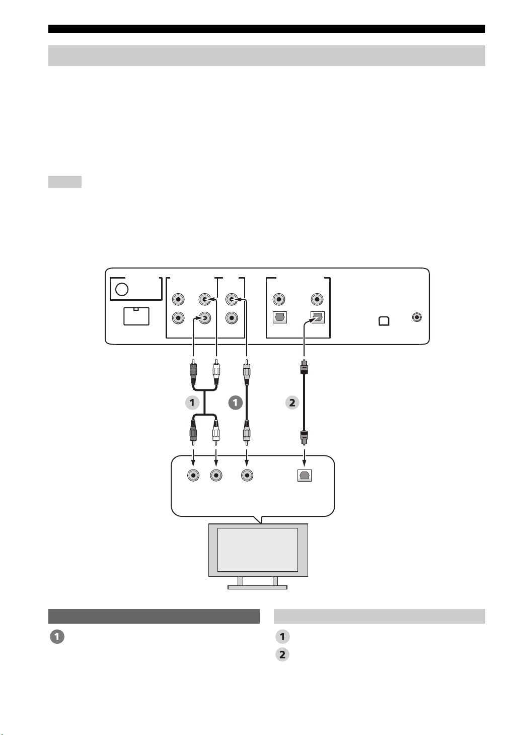
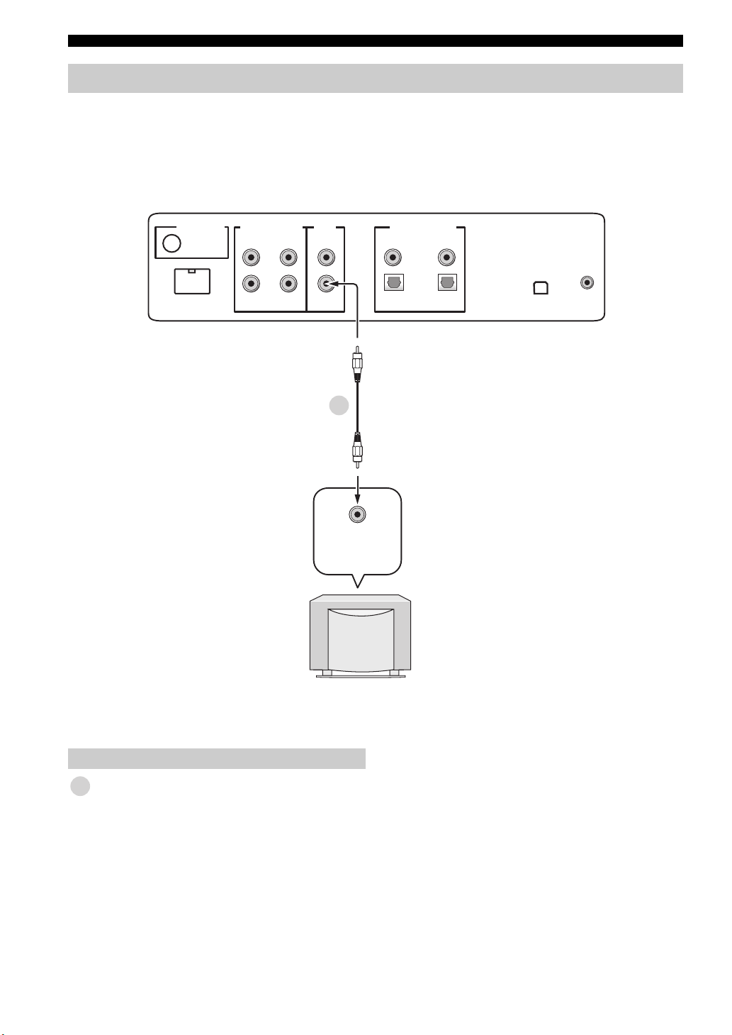
Connecting a TV
For audio connection, connect the analog audio output jacks on your TV to the TV/STB AUDIO INPUT jacks on this
unit. If your TV has an optical digital output jack, connect the optical digital output jack on your TV to the TV/STB
OPTICAL DIGITAL INPUT jack on this unit.
For video connection, connect the video input jack on your TV to the VIDEO OUT jack on this unit to display the OSD
for easy viewing when you adjust the system parameters in SET MENU.
y
To prevent the optical cable from being unplugged, affix the optical cable in the supplied cable clamp (see page 20).
Notes
• If you make analog and optical digital audio connections at the same time as shown in the illustration below, the digital audio signals
input at the TV/STB OPTICAL DIGITAL INPUT jack take priority over the analog audio signals input at the TV/STB AUDIO
INPUT jacks.
• Even if you connect your TV and this unit via the HDMI jack, you need to connect the video input jack on your TV to the VIDEO
OUT jack on this unit in order to display the OSD of this unit.
Rear panel of this unit
(U.S.A. and Canada models)
DOCK
AUDIO INPUTANTENNA
AUX 1 AUX 1
RL
Analog
output
TV/STB
audio
VIDEO
SUBWOOFER
Video
input
DIGITAL INPUTOUT
AUX 2
DVD
COAXIAL
OPTICAL
TV/STB
Optical
digital
output
IR INXM
TV
Video Audio
OSD video pin cable Audio pin cable
Optical cable
22 En
Page 25
Connections
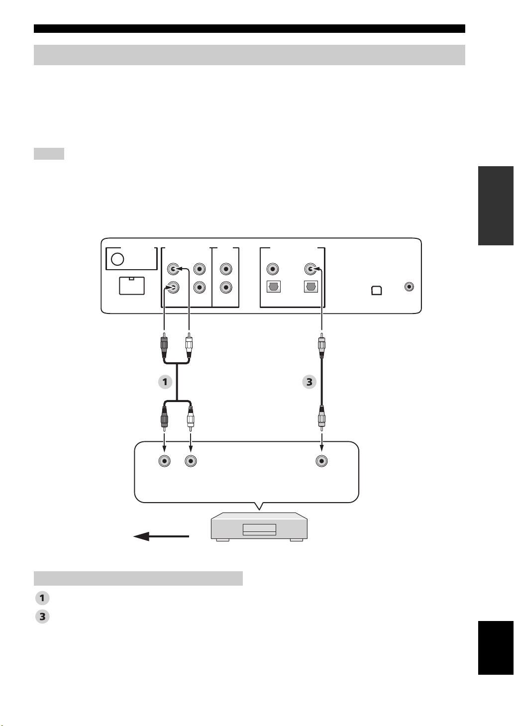
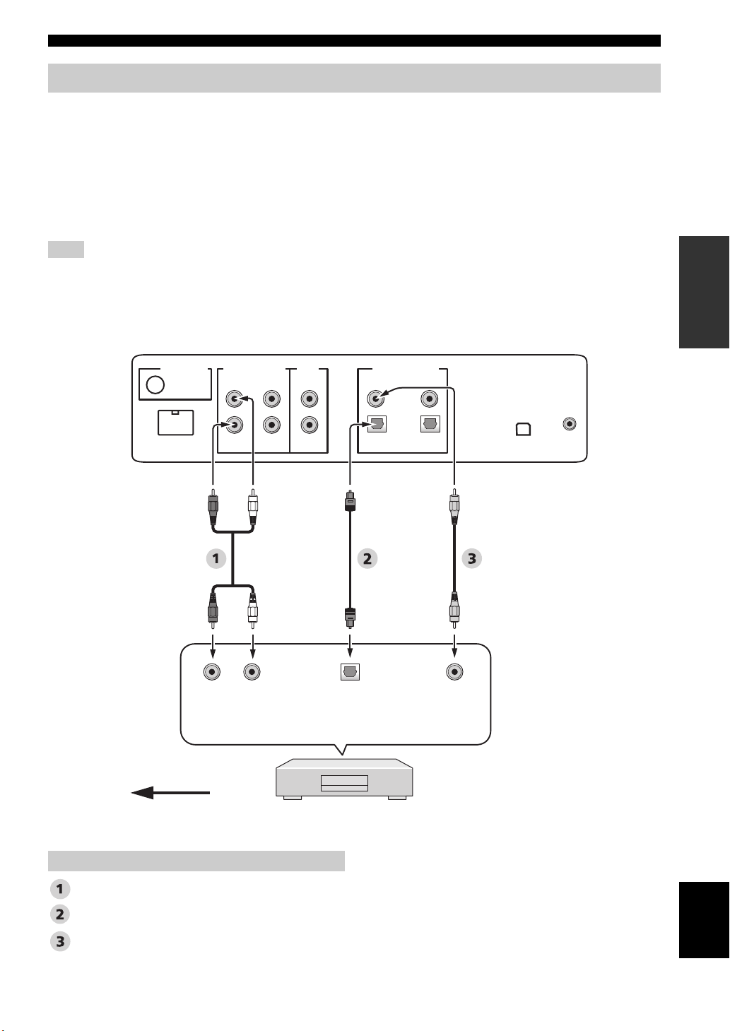
Connecting a DVD player/recorder
Connect the coaxial digital output jack on your DVD player/recorder to the DVD COAXIAL DIGITAL INPUT jack on
this unit. When you connect this unit to your DVD/VCR combo player/recorder, connect the analog audio output jacks on
your DVD/VCR combo player/recorder to the AUX 1 AUDIO INPUT jacks on this unit in addition to the coaxial digital
audio connection.
y
To prevent the optical cable from being unplugged, affix the optical cable in the supplied cable clamp (see page 20).
Notes
• Check that your DVD player/recorder is properly set to output Dolby Digital and DTS digital audio signals. If not, adjust the system
settings of your DVD player/recorder. For details, refer to the operation manual supplied with your DVD player/recorder.
• If your DVD player/recorder does not have a coaxial digital output jack, make an optical digital audio connection instead (see
page 27).
Rear panel of this unit
(U.S.A. and Canada models)
PREPARATION
DOCK
AUDIO INPUTANTENNA
AUX 1 AUX 1
*
LR
Analog
audio
output
VIDEO
SUBWOOFER
TV/STB
For the DVD/VCR combo
player/recorder
connection
AUX 2
DIGITAL INPUTOUT
DVD
COAXIAL
OPTICAL
TV/STB
Coaxial
digital
output
IR INXM
Video signal to the TV
Audio
Audio pin cable
Digital audio pin cable
DVD player/recorder
English
23 En
Page 26
Connections
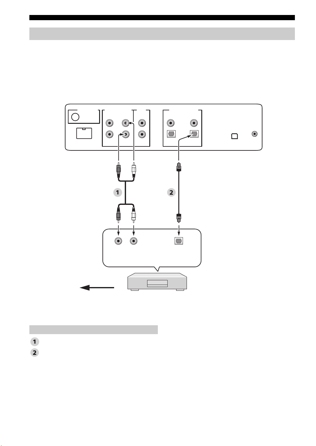
Connecting a digital satellite tuner or a cable TV tuner
Connect the optical digital output jack on your digital satellite tuner or cable TV tuner to the TV/STB OPTICAL
DIGITAL INPUT jack on this unit. Connect the analog audio output jacks on your digital satellite tuner or cable TV
tuner to the TV/STB AUDIO INPUT jacks on this unit.
y
To prevent the optical cable from being unplugged, affix the optical cable in the supplied cable clamp (see page 20).
Rear panel of this unit
(U.S.A. and Canada models)
DOCK
AUDIO INPUTANTENNA
AUX 1 AUX 1
Analog
TV/STB
LR
audio
output
VIDEO
SUBWOOFER
DIGITAL INPUTOUT
AUX 2
Optical
digital
output
DVD
COAXIAL
OPTICAL
TV/STB
IR INXM
Video signal to the TV
*
This connection (except for a game console) is not
necessary if your TV has a built-in digital satellite
tuner, cable TV tuner, or digital airwave tuner.
Audio
Audio pin cable
Optical cable
24 En
Digital satellite tuner
or cable TV tuner
Page 27
Connections
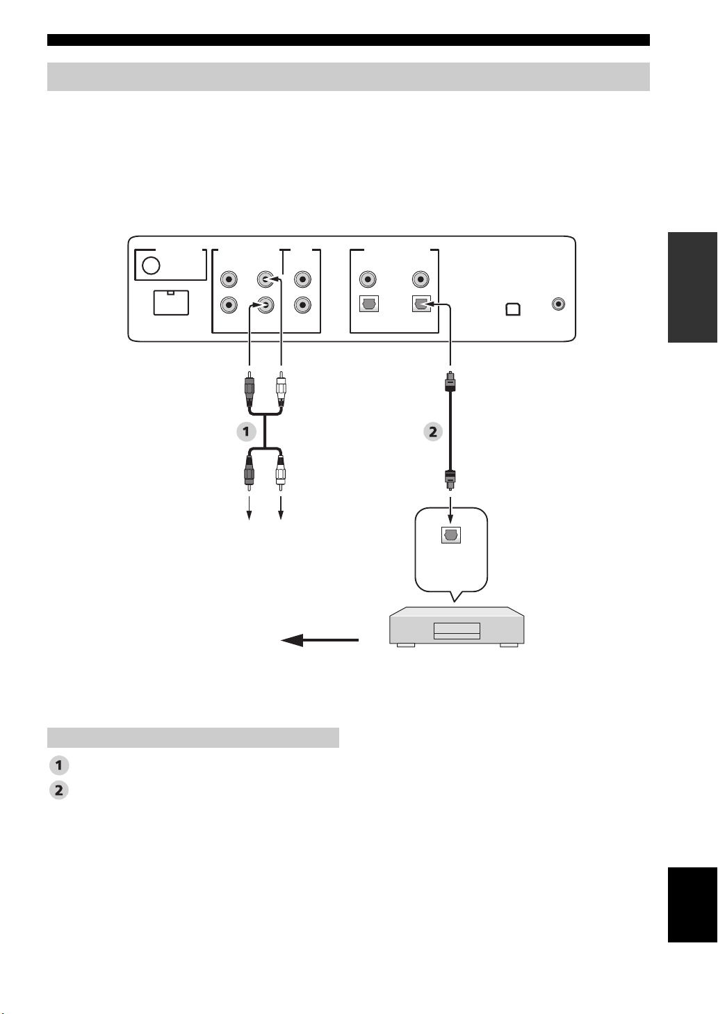
Connecting a digital airwave tuner
Connect the TV/STB AUDIO INPUT jacks on this unit to the analog audio output jacks on your TV. Connect the optical
digital output jack on your digital airwave tuner to the TV/STB OPTICAL DIGITAL INPUT jack on this unit in addition
to the analog audio connection. By doing so, you can enjoy both analog and digital broadcasts.
y
To prevent the optical cable from being unplugged, affix the optical cable in the supplied cable clamp (see page 20).
Rear panel of this unit
(U.S.A. and Canada models)
DIGITAL INPUTOUT
AUX 2
DVD
COAXIAL
OPTICAL
TV/STB
IR INXM
DOCK
AUDIO INPUTANTENNA
AUX 1 AUX 1
TV/STB
VIDEO
SUBWOOFER
PREPARATION
*
Audio pin cable
Optical cable
Connect to the analog
audio output jacks on
the TV.
Video signal to the TV
This connection (except for a game console) is not
necessary if your TV has a built-in digital satellite
tuner, cable TV tuner, or digital airwave tuner.
Audio
Optical
digital
output
Digital airwave tuner
English
25 En
Page 28
Connections
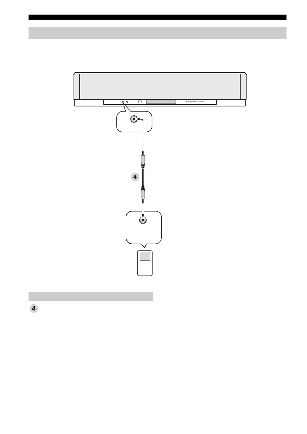
Connecting a portable audio player
Connect the analog audio output jack on your portable audio player to the AUX 3 input jack on the front panel of this
unit.
Front panel of this unit
AUX 3
Audio
3.5 mm stereo mini plug cable
Analog
audio
output
Portable audio player
26 En
Page 29
Connections
Connecting other external components
If your component supports optical digital connections, connect the optical digital output jack on your component
(e.g., DVD player/recorder) to the AUX 1 OPTICAL DIGITAL INPUT jack on this unit. If your component does not
support optical digital connections, connect the coaxial digital output jack on your component to the AUX 2 COAXIAL
DIGITAL INPUT jack on this unit.
If your component does not support any digital connections, connect the analog audio output jacks on your component
(e.g., VCR) to the AUX 1 AUDIO INPUT jacks on this unit.
y
To prevent the optical cable from being unplugged, affix the optical cable in the supplied cable clamp (see page 20).
Note
If you make analog and digital audio connections at the same time as shown in the illustration below, the digital audio signals input at
the AUX 1 OPTICAL DIGITAL INPUT or AUX 2 COAXIAL DIGITAL INPUT jack take priority over the analog audio signals input
at the AUX 1 AUDIO INPUT jacks.
Rear panel of this unit
(U.S.A. and Canada models)
PREPARATION
DOCK
AUDIO INPUTANTENNA
AUX 1 AUX 1
LR
Analog
audio
output
TV/STB
VIDEO
SUBWOOFER
Optical
digital
output
DIGITAL INPUTOUT
AUX 2
DVD
COAXIAL
OPTICAL
TV/STB
Coaxial
digital
output
IR INXM
Video signal to the TV
Audio
Audio pin cable
Optical cable
Digital audio pin cable
DVD player/recorder, VCR,
game console, CD player, etc.
English
27 En
Page 30
Connections
Connecting a subwoofer
Connect the monaural input jack on your subwoofer to the SUBWOOFER OUT jack on this unit.
This connection alone does not output sound from the connected subwoofer. To output sound from the connected
subwoofer, turn on the power of your subwoofer and then run AUTO SETUP (see page 35) or select SWFR for BASS
OUT in SUBWOOFER SET (see page 78).
Rear panel of this unit
(U.S.A. and Canada models)
DOCK
AUDIO INPUTANTENNA
AUX 1 AUX 1
TV/STB
VIDEO
SUBWOOFER
DIGITAL INPUTOUT
AUX 2
5
Monaural
input
COAXIAL
OPTICAL
TV/STB
DVD
IR INXM
Subwoofer pin cable
5
28 En
Subwoofer
Audio
Page 31

Connecting the FM antenna
Connect the supplied FM antenna to the FM ANTENNA jack on this unit.
FM indoor antenna (supplied)
Rear panel of this unit
(U.S.A. and Canada models)
Connections
DIGITAL INPUTOUT
AUX 2
DVD
COAXIAL
OPTICAL
TV/STB
IR INXM
DOCK
AUDIO INPUTANTENNA
AUX 1 AUX 1
TV/STB
VIDEO
SUBWOOFER
About the IR IN terminal (U.S.A. and Canada models only)
The IR IN terminal does not support normal external component connection. This is a control expansion terminal for
commercial use only.
DIGITAL INPUT
AUX 2
Rear panel of this unit
(U.S.A. and Canada models)
DVD
COAXIAL
OPTICAL
TV/STB
IR INXMAUX 1
IR IN terminal
PREPARATION
Connecting the AC power supply cable
Once all other connections are complete, plug the AC power supply cable into the AC wall outlet.
To the AC wall outlet
English
29 En
Page 32

GETTING STARTED
Getting started
Installing batteries in the remote control
Press
1 Press and hold the mark on the battery
cover and then open the cover.
y
Remove the transparent sheet before using the remote control.
Operation range of the remote control
The remote control transmits a directional infrared beam.
Use the remote control within 6 m (20 ft) of this unit and
point it toward the remote control sensor of this unit
during operation.
2 Insert the two supplied batteries (AA, R6,
UM-3) into the battery compartment.
Make sure you insert the batteries according to the
polarity markings (+/–).
3 Close the battery cover.
Notes
• Change all of the batteries if you notice the following
conditions: the operation range of the remote control decreases
or the transmission indicator does not light up or becomes dim.
• Do not use old batteries together with new ones.
• Do not use different types of batteries (such as alkaline and
manganese batteries) together. Read the packaging carefully as
these different types of batteries may have the same shape and
color.
• Exhausted batteries may leak. If the batteries have leaked,
dispose of them immediately. Avoid touching the leaked
material or letting it come into contact with clothing, etc. Clean
the battery compartment thoroughly before installing new
batteries.
• Do not throw away batteries with general house waste. Dispose
of them correctly in accordance with your local regulations.
• The memory stored in the remote control may be erased in the
following cases:
– The remote control is left without batteries for more than two
minutes.
– Exhausted batteries remain in the remote control.
– The buttons on the remote control are accidentally pressed
when you change batteries.
• If the memory stored in the remote control is unwantedly
erased, insert new batteries and set the remote control codes
again.
Approximately
6 m (20 ft)
45 45
Notes
• Do not spill water or other liquids on the remote control.
• Do not drop the remote control.
• Do not leave or store the remote control in the following places:
– places of high humidity, such as near a bath
– places of high temperatures, such as near a heater or a stove
– places of extremely low temperatures
– dusty places
• Do not expose the remote control sensor of this unit to direct
sunlight or lighting such as inverted fluorescent lamps.
• If the batteries grow old, the effective operation range of the
remote control decreases considerably. If this happens, replace
the batteries with two new ones as soon as possible.
30 En
Page 33

Getting started
Turning on this unit or setting it to the standby mode
INPUT
+
STANDBY/ON
VOLUME
POWERPOWERSTANDBY/ON
AV
TV
INPUT1
DOCK
AUX3
TV
MACRO
MEMORYSEARCH
AUX1 AUX2
DVD
TV
STB
PRESET/TUNE
CATFM/XM
(U.S.A. and Canada models)
2 Press STANDBY/ON again to set this unit to
the standby mode.
Note
When this unit is in the standby mode, only STANDBY/ON on
the front panel or on the remote control is operational, and the
other control buttons on the front panel or on the remote control
are not operational until the power of this unit is turned on.
SETUP
1 Press STANDBY/ON to turn on the power of
this unit.
The volume level appears in the front panel display,
and the current input source and beam mode are
displayed.
STANDBY/ON
STANDBY/ON
Front panel
or
Remote control
VOLUME 30
Current volume level
DVD MY SUR
Current input
source
Current beam
mode
English
31 En
Page 34

USING SET MENU
Using SET MENU
Displaying the OSD (on-screen display)
This section describes how to display the OSD (on-screen display) of this unit on your TV screen and to set the
parameters for your listening room. Once this is complete, you can enjoy real surround sound while watching TV in the
comfort of your own home.
1 Check that the video input jack on your TV is
connected to the VIDEO OUT jack on this unit
to display the OSD of this unit.
2 Press STANDBY/ON to turn on the power of
this unit.
STANDBY/ON
STANDBY/ON
Front panel
or
Remote control
3 Turn on the power of your TV.
The following screen appears on your TV.
YSP-3000
Push [MENU] to begin set-up
OSD screen example
If the OSD does not appear, use the remote control
supplied with your TV to switch the video input until
the OSD appears.
32 En
Page 35

The flow chart of SET MENU
The following diagram illustrates the overall flow of the setup procedure.
Run LANGUAGE SETUP.
See “Changing OSD language” on page 34.
Run AUTO SETUP (IntelliBeam).
See “AUTO SETUP (IntelliBeam)” on page 35.
Look for a remedy.
See “Error messages for AUTO SETUP” on page 41 for a complete list of error
messages and possible remedies.
Using SET MENU
If an error occurs
SETUP
Play back audio signals or adjust the settings for the beam mode and the CINEMA DSP.
See “Playback” on page 45, “Enjoying surround sound” on page 54, and “Using sound field programs” on
page 63.
If you want to make additional settings
and adjustments
Run MANUAL SETUP.
See “MANUAL SETUP” on page 72.
y
• If you cannot clearly hear a sound beam from a specific channel, adjust settings for
SETTING PARAMETERS (see page 74) or for BEAM ADJUSTMENT (see page 75) in
BEAM MENU.
• If there are acoustically absorbent objects such as curtains in the path of the sound beams,
adjust settings for TREBLE GAIN in BEAM MENU (see page 77).
English
33 En
Page 36

CHANGING OSD LANGUAGE
Changing OSD language
This feature allows you to select the language of your choice that appears in SET MENU of this unit.
1 Set the operation mode selector to YSP.
TV/AV
YSP
2 Press MENU.
The SET MENU screen appears on your TV.
SET MENU
;MEMORY
MENU
y
• The control buttons used for SET MENU are displayed at
the bottom of the screen.
• To return to the previous screen while using SET MENU,
press RETURN.
• To exit from SET MENU, press MENU once more.
• You can also perform the following operations while
viewing information in the front panel display.
.
;AUTO SETUP
;MANUAL SETUP
;LANGUAGE SETUP
p
[ ]/[ ]:Up/Down
p
[ENTER]:Enter
4 Press / to select the desired language,
and press ENTER.
ENTER
Choices: ENGLISH (English), DEUTSCH (German),
Français (French), ESPAÑOL (Spanish),
ITALIANO (Italian), NEDERLANDS (Dutch),
Русский (Russian)
ENTER
3 Press / to select LANGUAGE SETUP,
and press ENTER.
The following screen appears on your TV.
ENTER
ENTER
;LANGUAGE SETUP
ENGLISH
.
DEUTSCH
Francais
ESPANOL
ITALIANO
NEDERLANDS
p
[ ]/[ ]:Select
p
[ENTER]:Return
34 En
Page 37

AUTO SETUP (INTELLIBEAM)
AUTO SETUP (IntelliBeam)
This unit creates a sound field by reflecting sound beams on the walls of your listening room and by broadening the
cohesion of all the channels. Just as you would arrange the speaker position of other audio systems, you need to set the
beam angle to enjoy the best possible sound from this unit.
This unit employs the beam optimization and sound optimization features with the aid of the supplied IntelliBeam
microphone, allowing you to avoid troublesome listening-based setup and achieving highly accurate sound adjustments
that best match your listening environment. We call these two features “IntelliBeam” generically.
Beam optimization:
This feature optimizes the beam angle so that the parameter best matches your listening environment.
Sound optimization:
This feature optimizes the beam delay, volume, and quality so that the parameters best match your listening environment.
The flow chart of AUTO SETUP
This unit performs a series of checks to optimize the beam angle, delay, volume, and quality. You can choose to optimize
all or part of the parameters.
Checking the environment of
your listening room
*1
Optimizing the beam angle
*2 *3
Checking the subwoofer and
optimizing the beam delay,
frequency, and volume
Beam
optimization
Sound
optimization
Notes
*1 The beam angle checking procedure is skipped if SOUND
OPTIMZ only is selected.
2
*
The sound optimization procedure is skipped if BEAM
OPTIMZ only is selected.
3
*
The subwoofer checking procedure is skipped if BEAM
OPTIMZ only is selected.
SETUP
35 En
English
Page 38

AUTO SETUP (IntelliBeam)
Installing the IntelliBeam microphone
The supplied IntelliBeam microphone collects and analyzes the sound that this unit produces in your actual listening
environment. Follow the procedure below to connect the IntelliBeam microphone to this unit and make sure that the
IntelliBeam microphone is placed in a proper location and that there are no large obstacles between the IntelliBeam
microphone and the walls in your listening room.
Notes
• After you have completed the AUTO SETUP procedure, be sure to disconnect the IntelliBeam microphone.
• The IntelliBeam microphone is sensitive to heat.
– Keep it away from direct sunlight.
– Do not place it on top of this unit.
• Do not connect the IntelliBeam microphone to an extension cable as doing so may result in an inaccurate sound optimization.
• An error may occur during the AUTO SETUP procedure if the IntelliBeam microphone is not properly placed in your listening room.
To avoid the possibility of an error:
– Do not place the IntelliBeam microphone to the extreme right or left from the center of this unit.
– Do not place the IntelliBeam microphone within 1.8 m (6.0 ft) from the front of this unit.
– Do not place the IntelliBeam microphone more than 1 m (3.3 ft) upper or lower from the center height of this unit.
• Make sure that there are no obstacles between the IntelliBeam microphone and the walls in your listening room as these objects
obstruct the path of sound beams. However, any objects that are in contact with the walls will be regarded as a protruding part of the
walls.
• The best possible results are achieved if the IntelliBeam microphone is placed at the same height as your ears would be when you are
seated in your listening position. However, if this is not possible, you can manually fine-tune the sound beam angle and balance the
sound beam output levels using MANUAL SETUP (see page 72) once the AUTO SETUP procedure is completed.
• If a subwoofer with adjustable volume and crossover/high-cut frequency controls is connected to
this unit, set the volume between 10 and 12 o’clock as viewed on a conventional clockface and set
the crossover/high-cut frequency to the maximum.
VOLUME
CROSSOVER
HIGH CUT
1 Press STANDBY/ON to turn off the power of
this unit.
STANDBY/ON
STANDBY/ON
Front panel
or
Remote control
2 Connect the supplied IntelliBeam
microphone to the INTELLIBEAM MIC jack on
the front panel.
INTELLIBEAM MIC
MIN MAX MIN
Subwoofer
MAX
3 Place the IntelliBeam microphone on a flat
level surface more than 1.8 m (6.0 ft) from the
front of the unit and within 1 m (3.3 ft) upper
or lower from the center height of the unit
with the IntelliBeam microphone facing
upward at your normal listening position.
Note
Be sure to place the IntelliBeam microphone on an
imaginary center line drawn from this unit.
y
You may want to use the supplied cardboard microphone
stand to affix the IntelliBeam microphone at the same height
as your ears would be when you are seated in your listening
position.
IntelliBeam
microphone
Sofa
Within 1 m (3.3 ft)
upper or lower
from the center
height
More than
1.8 m (6.0 ft)
Cardboard
microphone stand
36 En
Page 39

AUTO SETUP (IntelliBeam)
Using AUTO SETUP (IntelliBeam)
Once the IntelliBeam microphone is firmly connected to
this unit and properly placed in your listening room,
follow the procedure below to start the AUTO SETUP
procedure.
You can also enter the AUTO SETUP procedure simply by
pressing and holding AUTO SETUP for more than two
seconds. In this case, this unit performs both of the beam
optimization and sound optimization procedures.
Center line
IntelliBeam
microphone
■ Assembling the supplied cardboard
microphone stand
You will find three separate parts (one circular part and
two longitudinal parts) of the cardboard microphone stand
originally put together.
12
34
INPUT
+
STANDBY/ON
VOLUME
AUX1 AUX2
DVD
TV
STB
PRESET/TUNE
CATFM/XM
AUTO
SETUP
VOL MODE
5BEAM ST+3BEAM 3BEAM
STEREO
MY BEAM
4
MUSIC MOVIE
789
OFF
+10
0
ENHANCER MENU
ENTRY
AV
INPUT1
INPUTMODE
5
POWERPOWERSTANDBY/ON
TV
DOCK
AUX3
TV
MACRO
MEMORYSEARCH
SLEEP
321
MY SUR.
6
SPORTS
SUR. DECODE
SETUP
1 Disassemble the three parts of the cardboard
microphone stand originally put together.
2 Insert one of the longitudinal part into the
crevice of the other longitudinal part.
3 Place the circular part on top of the two
combined longitudinal parts.
4 Place the supplied IntelliBeam microphone
on top of the circular part.
CAT/
A-E
ENTER
VOLUME
TV/AV
YSP
RETURNDISPLAY
TV VOL
CH
(U.S.A. and Canada models)
English
37 En
Page 40

AUTO SETUP (IntelliBeam)
Notes
• Make sure that your listening room is as quiet as possible while
this unit is performing the AUTO SETUP procedure.
• To achieve the best results possible, evacuate yourself from
your listening room until the AUTO SETUP procedure is
completed so that you may not obstruct the path of sound
beams.
• Be advised that it is normal for loud test tones to be output
during the AUTO SETUP procedure.
• The AUTO SETUP procedure may not be run successfully if
this unit is installed in one of the rooms described in “Before
installing this unit” on page 16. In such cases, run MANUAL
SETUP (see page 72) to manually adjust the corresponding
parameters.
• If an error occurs, an error buzzer is played, the AUTO SETUP
procedure stops, and an error message appears on the screen.
See “Error messages for AUTO SETUP” on page 41 for
appropriate remedies.
y
• The AUTO SETUP procedure takes about three minutes
maximum. A chime is played when the AUTO SETUP
procedure is run successfully.
• If there are curtains in your listening room, we recommend
following the procedure below.
1. Open the curtains to improve sound reflection.
2. Run BEAM OPTIMZ only.
3. Close the curtains.
4. Run SOUND OPTIMZ only.
• You can save the settings optimized by the AUTO SETUP
procedure (see page 42). A set of settings optimized according
to the specific conditions of your listening environment can be
recalled later depending on the varying conditions of your
listening environment (see page 43).
1 Press STANDBY/ON to turn on the power of
this unit.
If a subwoofer is connected to this unit, turn on the
power of the subwoofer.
3 Press MENU.
The SET MENU screen appears on your TV.
SET MENU
;MEMORY
MENU
y
• The control buttons used for SET MENU are displayed at
the bottom of the screen.
• To return to the previous screen while using SET MENU,
press RETURN.
• To exit from the SET MENU screen, press MENU again.
• You can start the BEAM+SOUND OPTIMZ procedure
simply by pressing and holding AUTO SETUP for more
than two seconds. Steps 4 and 5 are skipped and then the
screen shown in step 5 is displayed on your TV. Start the
AUTO SETUP procedure from step 6.
• You can also perform the following operations in the front
panel display.
4 Press / to select AUTO SETUP and
press ENTER.
The following screen appears on your TV.
ENTER
.
;AUTO SETUP
;MANUAL SETUP
;LANGUAGE SETUP
p
[ ]/[ ]:Up/Down
p
[ENTER]:Enter
ENTER
STANDBY/ON
STANDBY/ON
Front panel
or
Remote control
2 Set the operation mode selector to YSP.
TV/AV
YSP
38 En
;AUTO SETUP
.
1)BEAM+SOUND OPTIMZ
2)BEAM OPTIMZ only
3)SOUND OPTIMZ only
p
[ ]/[ ]:Up/Down
p
[ENTER]:Enter
Page 41

AUTO SETUP (IntelliBeam)
5 Press / to select BEAM+SOUND
OPTIMZ, BEAM OPTIMZ only, or SOUND
OPTIMZ only and then press ENTER.
The following screen appears on your TV.
ENTER
AUTO SETUP
PREPARATION & CHECK
Please connect the MIC.
Please place the MIC at least
1.8m/6ft away from the YSP
unit. The MIC should be set
at ear level when seated.
Measurement takes about 3min.
After [ENTER] is pressed,
please leave the room.
[ENTER]:Start [RETURN]:Cancel
BEAM+SOUND OPTIMZ
(Beam optimization and sound optimization)
Use to optimize the beam angle, delay, volume, and
quality so that the parameters best match your listening
environment.
It is recommended that you should select this optimization
feature in the following cases:
• If you make settings for the first time.
• If the unit has been relocated.
• If your listening room has been restructured.
• If the objects in your listening room (furniture, etc.)
have been rearranged.
This menu takes about three minutes.
BEAM OPTIMZ only
(Beam optimization only)
Use to optimize the beam angle so that the parameter best
matches your listening environment.
This menu takes about one minute.
SOUND OPTIMZ only
(Sound optimization only)
Use to optimize the beam delay, volume, and quality so
that the parameters best match your listening environment.
It is recommended that you should select this optimization
feature in the following cases:
• If you have opened or closed the curtains in your
listening room before using this unit.
• If you have manually set the beam angle.
This menu takes about two minutes.
ENTER
6 Check the following points once again before
starting the AUTO SETUP procedure.
• Is the IntelliBeam microphone firmly connected to
this unit?
• Is the IntelliBeam microphone placed in a proper
location?
• Are there any large obstacles in between the
IntelliBeam microphone and the walls in your
listening room?
7 Press ENTER to start the AUTO SETUP
procedure.
The following screen appears on your TV and the
AUTO SETUP procedure starts in 10 seconds.
Leave the room quietly before starting the AUTO
SETUP procedure.
ENTER
AUTO SETUP START
Will begin in 10sec
Please leave the room
**--------
[RETURN]:Cancel
If an error occurs, an error buzzer is played and an
error message is displayed. See “Error messages for
AUTO SETUP” on page 41 for a complete list of
error messages and their proper remedies. Follow the
instructions and perform the AUTO SETUP
procedure again.
← Flashes
SETUP
Note
You must optimize the beam angle in the BEAM OPTIMZ only
procedure before starting the SOUND OPTIMZ only procedure.
English
39 En
Page 42

AUTO SETUP (IntelliBeam)
8 Check that the following screen is displayed
on your TV.
The results of the AUTO SETUP procedure are
displayed on your TV.
Example 1
SHOW RESULT
←
MEASUREMENT COMPLETE
BEAM MODE :5 BEAM
SUBWOOFER :NOT APPLICABLE
[ENTER]:Save set-up.
[RETURN]:Do not save set-up.
Example 2
Flashes
SHOW RESULT
←
MEASUREMENT COMPLETE
ENVIRONMENT CHECK[FAILED]
BEAM MODE :5 BEAM
SUBWOOFER :YES
[ENTER]:Save set-up.
[RETURN]:Do not save set-up.
y
• If “ENVIRONMENT CHECK [FAILED]” is
displayed, we recommend running the AUTO SETUP
procedure again. For details, see step 9.
• If “SUBWOOFER : NOT APPLICABLE” is displayed
even though a subwoofer is connected to this unit,
increase the volume level of the subwoofer and run the
AUTO SETUP procedure again.
• Depending on the environment of your listening room,
the beam angle of front left and right, and surround left
and right may be set to the same value even if
“5 BEAM” is displayed as a result.
Flashes
9 Press ENTER to confirm the results or press
RETURN to cancel the results.
The following screen is displayed for two seconds
and then disappears from your TV.
AUTO SETUP COMPLETE
ENTER
Please remove the MIC from
the YSP and the listening
position.
If “ENVIRONMENT CHECK [FAILED]” is displayed in
step 8, the following screen is displayed after pressing
ENTER. In this case, see ERROR E-1 in “Error messages
for AUTO SETUP” on page 41. Press ENTER to exit
AUTO SETUP and then run the procedure again from
step 3.
AUTO SETUP COMPLETE
Your YSP unit may not be set
up correctly.
We recommend you try again.
Please press [ENTER] key to
exit.
10 Disconnect the IntelliBeam microphone from
the INTELLIBEAM MIC jack on the front
panel.
40 En
y
If you want to save and load settings, see “Using the system
memory” on page 42.
Page 43

■ Error messages for AUTO SETUP
Before the AUTO SETUP procedure starts
AUTO SETUP (IntelliBeam)
Error message Cause Remedy
ERROR E-2
No MIC detected. Please check
MIC connection and re-try.
The IntelliBeam microphone is not
connected to this unit.
Connect the IntelliBeam microphone to
this unit.
See
page
36
While the AUTO SETUP procedure is in progress
If one of the errors listed below except E-1 is displayed, press RETURN. In case you have started the AUTO SETUP
procedure by pressing AUTO SETUP in step 3, run the procedure again from step 3 after the screen disappears. In case
you have started the AUTO SETUP procedure by pressing MENU in step 3, run the procedure again from step 4 after the
screen in step 3 is displayed. Run MANUAL SETUP if the problem is difficult to be saved.
Error message Cause Remedy
ERROR E-1
Please test in quieter environment.
ERROR E-2
No MIC detected. Please check
MIC connection and re-try.
ERROR E-3
Unexpected control is detected.
Please re-try.
ERROR E-4
Please check MIC position. MIC
should be set in front of YSP.
ERROR E-5
Please check MIC position. MIC
should be set above 1.8m/6.0ft.
ERROR E-6
Volume level is lower than
expected. Please check MIC
position/connection and re-try.
ERROR E-7
Unexpected error happened.
Please re-try.
There is too much unwanted noise in
your listening room.
The IntelliBeam microphone was
disconnected while the AUTO SETUP
procedure was in progress.
Some other operations were performed
on this unit while the AUTO SETUP
procedure was in progress.
The IntelliBeam microphone is not
placed in front of this unit.
The IntelliBeam microphone is not
placed in the right distance from this
unit.
The IntelliBeam microphone cannot
collect the sound produced by this unit
because the sound output level is too low.
An internal system error occurred. Repeat the AUTO SETUP procedure.
Make sure that your listening room is as
quiet as possible. You may want to
choose certain hours during the day
when there is not much noise coming
from outside.
Make sure that the IntelliBeam
microphone is firmly connected to this
unit.
Do not perform any other operations
while the AUTO SETUP procedure is in
progress.
Make sure that the IntelliBeam
microphone is installed in front of this
unit.
Make sure that the IntelliBeam
microphone is installed more than 1.8 m
(6.0 ft) from the front of this unit and
within 1 m (3.3 ft) from the center height
of this unit.
Make sure that the IntelliBeam
microphone is firmly connected to this
unit and placed in a proper location. If
the problem persists, contact the nearest
authorized Yamaha service center for
assistance.
See
page
—
36
—
36
36
36
—
SETUP
41 En
English
Page 44

USING THE SYSTEM MEMORY
Using the system memory
Convenient usage of the system memory
You can save the current settings adjusted in SET MENU
in the system memory of this unit. It is handy to save
certain settings according to the varying conditions of
your listening environment. For example, if there are
curtains in the path of sound beams, the effectiveness of
the sound beams will vary depending on whether the
curtains are open or closed.
When the curtains are
open
When the curtains are
closed
Saving settings
1 Set the operation mode selector to YSP.
3 Press / to select MEMORY and press
ENTER.
The following screen appears on your TV.
ENTER
ENTER
;MEMORY
1)LOAD
.
2)SAVE
p
[ ]/[ ]:Up/Down
p
[ENTER]:Enter
4 Press / to select SAVE and press
ENTER.
The following screen appears on your TV.
TV/AV
YSP
2 Press MENU.
The SET MENU screen appears on your TV.
SET MENU
;MEMORY
MENU
y
• The control buttons used for SET MENU are displayed at
the bottom of the screen.
• To return to the previous screen while using SET MENU,
press RETURN.
• To exit from the SET MENU screen, press MENU once
more.
• You can also perform the following operations in the front
panel display.
.
;AUTO SETUP
;MANUAL SETUP
;LANGUAGE SETUP
p
[ ]/[ ]:Up/Down
p
[ENTER]:Enter
ENTER
ENTER
2)MEMORY SAVE
.
MEMORY1
MEMORY2
MEMORY3
p
[ ]/[ ]:Select
p
[ENTER]:Enter
42 En
Page 45

Using the system memory
5 Press / to select MEMORY1,
MEMORY2, or MEMORY3 and press ENTER.
The following screen appears on your TV.
ENTER
ENTER
2)MEMORY SAVE
MEMORY1 Save Now ?
Push [ENTER] to Save
6 Press ENTER again.
The new parameters are saved as MEMORY1,
MEMORY2, or MEMORY3. Once the parameters
are saved, the display returns to the SET MENU
screen.
2)MEMORY SAVE
ENTER
MEMORY1 Saving
Loading settings
You can recall the settings saved in “Saving settings” on
page 42 according to the varying conditions of your
listening environment.
1 Set the operation mode selector to YSP.
TV/AV
YSP
2 Press MENU.
The SET MENU screen appears on your TV.
SET MENU
;MEMORY
MENU
y
• The control buttons used for SET MENU are displayed at
the bottom of the screen.
• To return to the previous screen while using SET MENU,
press RETURN.
• To exit from the SET MENU screen, press MENU once
more.
• You can also perform the following operations in the front
panel display.
.
;AUTO SETUP
;MANUAL SETUP
;LANGUAGE SETUP
p
[ ]/[ ]:Up/Down
p
[ENTER]:Enter
SETUP
SET MENU
;MEMORY
.
;AUTO SETUP
;MANUAL SETUP
;LANGUAGE SETUP
p
[ ]/[ ]:Up/Down
p
[ENTER]:Enter
7 Press MENU to exit.
The SET MENU screen disappears from your TV.
MENU
3 Press / to select MEMORY and press
ENTER.
The following screen appears on your TV.
ENTER
ENTER
;MEMORY
1)LOAD
.
2)SAVE
p
[ ]/[ ]:Up/Down
p
[ENTER]:Enter
43 En
English
Page 46

Using the system memory
4 Press / to select LOAD and press
ENTER.
The following screen appears on your TV.
ENTER
ENTER
1)MEMORY LOAD
.
MEMORY1
MEMORY2
MEMORY3
p
[ ]/[ ]:Select
p
[ENTER]:Enter
5 Press / to select MEMORY1,
MEMORY2, or MEMORY3 and press ENTER.
The following screen appears on your TV.
6 Press ENTER again.
The new parameters saved as MEMORY1,
MEMORY2, or MEMORY3 are loaded. Once the
parameters are loaded, the display returns to the SET
MENU screen.
1)MEMORY LOAD
ENTER
MEMORY1 Loading
SET MENU
;MEMORY
.
;AUTO SETUP
;MANUAL SETUP
;LANGUAGE SETUP
p
[ ]/[ ]:Up/Down
p
[ENTER]:Enter
7 Press MENU to exit.
The SET MENU screen disappears from your TV.
ENTER
ENTER
1)MEMORY LOAD
MEMORY1 Load Now ?
Push [ENTER] to Load
MENU
44 En
Page 47

Playback
Selecting the input source
You can play back sound from the components connected
to this unit simply by pressing INPUT on the front panel
repeatedly or pressing one of the input selector buttons
(TV, STB, DVD, AUX1, AUX2, or AUX3) on the remote
control. The name of the selected input source and the
type of corresponding input mode appear in the front
panel display.
INPUT
+
STANDBY/ON
VOLUME
PLAYBACK
■ Front panel operations
Press INPUT on the front panel repeatedly to
toggle between TV, STB, DVD, AUX1, AUX2, and
AUX3.
The name of the corresponding input source and the type
of current input mode are displayed in the front panel
display.
■ Remote control operations
y
In addition to controlling this unit, you can also operate other AV
components if you set up the remote control with the appropriate
remote control codes and set the operation mode selector to TV/
AV to change the control area (see page 96).
Press TV to play back a TV program.
TV
TV
MY BEAM
+10
ENTRY
ENTER
INPUT1
INPUTMODE
5
DOCK
AUX3
TV
MACRO
MEMORYSEARCH
SLEEP
321
MY SUR.
6
SPORTS
SUR. DECODE
TV/AV
RETURNDISPLAY
YSP
AUX1 AUX2
DVD
STB
PRESET/TUNE
CATFM/XM
AUTO
SETUP
VOL MODE
5BEAM ST+3BEAM 3BEAM
STEREO
4
MUSIC MOVIE
789
OFF
0
ENHANCER MENU
CAT/
A-E
(U.S.A. and Canada models)
TV/STB AUTO
Name of the selected
input source
Press STB to play back a satellite broadcast.
Type of the selected
input mode
STB
TV/STB AUTO
Press DVD to play back a DVD.
DVD
DVD AUTO
OPERATION
BASIC
English
45 En
Page 48

Playback
Press AUX1 (or AUX2) to play back a component
connected to the AUX 1 (or AUX 2) jack on the
rear panel of this unit.
AUX1
2 Switch to the video input on your TV using
the remote control supplied with the TV and
display the DVD menu screen.
Note
If necessary, turn down the volume of your TV until no
sound is heard.
AUX1 AUTO
Press AUX3 to play back a component connected
to the AUX 3 input jack on the front panel.
AUX3
AUX3
Playing back sources
Once an input source is selected (see page 45), you can
play back the selected input source.
Note
This section uses a DVD player as an example of the playback
source.
y
For details on your TV and DVD player, refer to the respective
owner’s manual.
3 Press DVD to select DVD as the input source.
DVD
4 Play back DVD on your DVD player using the
supplied remote control.
Audio signals from your DVD player are output from
this unit.
y
• You can use the supplied demonstration DVD to check the
digital signals being input at the DVD player with the digital
connection (optical/coaxial/HDMI). The input channel and LFE
indicators light up when this unit detects the 5.1-channel signal
input at the optical/coaxial/HDMI jack. If the indicator
lights up, confirm the settings of the digital output, bitstream
output, DTS output, and/or HDMI output of the DVD player.
• If the output volume is too low, increase the volume of this unit
to around 45.
• If you have set the appropriate remote control codes for your
TV and DVD player, you can use the remote control supplied
with this unit to operate these components. For details on how
to set remote control codes, see page 96.
PCM
1 Turn on the power of your DVD player.
46 En
Page 49

Adjusting the volume
INPUT
+
STANDBY/ON
VOLUME
■ Muting the sound
VOLUME
MUTE
TV VOL
CH
TV INPUT TV MUTE
1 Press MUTE to mute the sound.
“AUDIO MUTE ON” appears in the front panel
display, and the volume level indicator flashes.
MUTE
Playback
VOLUME
MUTE
TV VOL
CH
TV INPUT TV MUTE
Press VOLUME +/– to increase or decrease the
volume level.
The numeric value of the volume level appears in the front
panel display.
Control range: MIN (minimum), 01 to 99,
MAX (maximum)
VOLUME
or
+
VOLUME
Front panel
Remote control
VOLUME 30
AUDIO MUTE ON
Flashes
DVD 5BEAM
2 Press MUTE again (or press VOLUME +/–) to
resume the sound output.
“AUDIO MUTE OFF” appears temporarily in the
front panel display (or the numeric value of the
current volume level appears if you press VOLUME
+/–), and the volume level indicator lights up.
VOLUME
MUTE
or
Lights up
OPERATION
BASIC
Notes
• The volume level of all input sources (including multi-channel
as well as stereo sources) changes at the same time.
• One volume level increases or decreases each time you press
VOLUME +/–.
• You can continuously increase or decrease the volume level if
you press and hold VOLUME +/–.
AUDIO MUTE OFF
Note
The sound output of all input sources (including multi-channel as
well as stereo sources) is muted at the same time.
y
You can select whether the sound output is to be muted
completely or by 20 dB when you press MUTE (see page 78).
English
47 En
Page 50

FM TUNING
FM tuning
There are two tuning methods: automatic and manual. Automatic tuning is effective when the radio signal is strong and
there is no interference. If the radio signal is weak, tune into the FM station manually. You can also use the automatic and
manual preset tuning features to store up to 40 stations in total (A1 to E8: 5 preset station groups with 8 preset station
numbers each).
y
• This section exceptionally uses the remote control for Europe, Australia, Asia, and Korea models.
• When the operation mode selector is set to TV/AV, you can operate all FM functions. When the operation mode selector is set to YSP,
you can only operate the functions described in “Selecting a preset station” (see page 52).
Note
Orient the connected FM antenna for the best reception.
FM controls and functions
■ Remote control functions
Set the operation mode selector (8) to TV/AV before
tuning or preset tuning.
POWERPOWERSTANDBY/ON
AV
TV
1
2
3
4
5
AUX1 AUX2
DVD
TV
STB
PRESET/TUNE
A-E
FM
AUTO
SETUP
VOL MODE
5BEAM ST+3BEAM 3BEAM
STEREO MY SUR.
4
MUSIC MOVIE
789
OFF
0
ENHANCER
A-E
VOLUME
MUTE
AUX3
TV
MACRO
INPUT1
MEMORYSEARCH
SLEEP
INPUTMODE
321
MY BEAM
6
5
SPORTS
SUR. DECODE
+10
MENU
ENTRY
ENTER
RETURNDISPLAY
TV VOL
CH
TV INPUT TV MUTE
TV/AV
YSP
6
7
8
1 FM
Selects FM as the input source. This unit is tuned into the
last selected FM station.
y
U.S.A. and Canada models use FM/XM.
2 PRESET/TUNE
Switches between the preset search mode and the
frequency search mode (see page 51).
3 Numeric buttons
Use numbers 1 through 8 to select the preset station
numbers (see page 52).
4 ENTRY ( / )
• Selects the preset station numbers (1 to 8) when the
colon (:) is displayed in the front panel display
(see page 52).
• Selects the tuning frequency when the colon (:) is not
displayed in the front panel display (see page 49).
5 A-E ( / )
Selects the preset station groups (A to E) (see page 51).
y
U.S.A. and Canada models use CAT/A-E .
6 MEMORY
• Stores a preset station in the memory (see page 51).
• Hold down this button for more than three seconds to
start automatic preset tuning (see page 50).
48 En
(Europe, Australia, Asia, and
Korea models)
7 SEARCH
Switches between automatic tuning (the AUTO indicator
is turned on) and manual tuning (the AUTO indicator is
turned off) (see page 49).
8 Operation mode selector
Selects the operation mode of this unit.
Page 51

FM tuning
Automatic tuning
Automatic tuning is effective when the radio station
signals are strong and there is no interference.
1 Set the operation mode selector to TV/AV.
TV/AV
YSP
2 Press FM to select FM as the input source.
“FM” appears in the front panel display.
FM
y
• You can also press INPUT on the front panel repeatedly to
select FM as the input source.
• If “XM” appears in the front panel display, press FM/XM
again to display “FM” (U.S.A. and Canada models only).
3 Press SEARCH repeatedly until the AUTO
indicator lights up in the front panel display.
SEARCH
4 Press ENTRY ( / ) once to begin
automatic tuning.
When this unit is tuned into an FM station, the
TUNED indicator lights up and the frequency of the
station appears in the front panel display.
• Press to tune into a higher frequency.
• Press to tune into a lower frequency.
ENTRY
ENTER
Manual tuning
If the desired FM station signal is weak, tune into it
manually.
Note
Manual tuning automatically switches the tuner to the monaural
reception mode to increase the signal quality.
1 Set the operation mode selector to TV/AV.
TV/AV
YSP
OPERATION
BASIC
Lights up
A FM 88.9 MHz
No colon (:)
If a colon (:) appears in the front panel display, tuning
is not available. Press PRESET/TUNE to turn the
colon (:) off.
2 Press FM to select FM as the input source.
“FM” appears in the front panel display.
FM
y
• You can also press INPUT on the front panel repeatedly to
select FM as the input source.
• If “XM” appears in the front panel display, press FM/XM
again to display “FM” (U.S.A. and Canada models only).
English
49 En
Page 52

FM tuning
3 Press SEARCH repeatedly until the AUTO
indicator disappears from the front panel
display.
SEARCH
A FM 88.9 MHz
No colon (:)
If a colon (:) appears in the front panel display, tuning
is not available. Press PRESET/TUNE to turn the
colon (:) off.
4 Press ENTRY ( / ) to tune into the
desired station manually.
ENTRY
ENTER
2 Press FM to select FM as the input source.
“FM” appears in the front panel display.
FM
y
• You can also press INPUT on the front panel repeatedly to
select FM as the input source.
• If “XM” appears in the front panel display, press FM/XM
again to display “FM” (U.S.A. and Canada models only).
3 Press and hold MEMORY for more than three
seconds.
The preset station group and number, the MEMORY
indicator, and the AUTO indicator flash. Automatic
preset tuning starts from the current frequency and
proceeds toward higher frequencies.
MEMORY
Flashes
y
Hold down the button for quick search.
Automatic preset tuning
You can use the automatic preset tuning feature to store up
to 40 FM stations with strong signals (A1 to E8: 5 preset
station groups with 8 preset station numbers each). You
can recall the preset stations easily by selecting the preset
station groups and numbers.
1 Set the operation mode selector to TV/AV.
TV/AV
YSP
A1:FM 88.9 MHz
Flashes
When automatic preset tuning is completed, the front
panel display shows the frequency of the last preset
station.
Notes
• When you overwrite an existing preset station, the
previously stored FM station is cleared.
• If the number of automatically preset stations does not
reach 40 (E8), this unit automatically stops searching.
• Only FM stations with sufficient signal strength are preset
automatically. If the desired station is weak in signal
strength, tune into it manually and store it as described in
“Manual preset tuning” on page 51.
50 En
Page 53
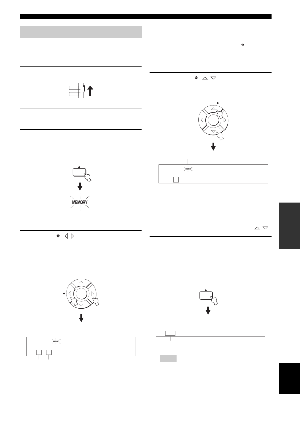
Manual preset tuning
You can also store up to 40 stations (A1 to E8: 5 preset
station groups with 8 preset station numbers each)
manually.
1 Set the operation mode selector to TV/AV.
TV/AV
YSP
2 Tune into the desired FM station.
See page 49 for tuning instructions.
3 Press MEMORY.
The MEMORY indicator flashes in the front panel
display for approximately 10 seconds.
MEMORY
FM tuning
y
• If the colon (:) does not appear, press PRESET/TUNE to
display the colon.
• U.S.A. and Canada models use CAT/A-E .
• Even when the operation mode selector is set to YSP, you
can select the desired preset group by pressing A-E (CAT
for U.S.A. and Canada models).
5 Press ENTRY ( / ) to select a preset
station number (1 to 8) while the MEMORY
indicator is flashing.
ENTRY
ENTER
Flashes
A1:FM 88.9 MHz
Flashes
4 Press A-E ( / ) repeatedly to select a
preset station group (A to E) while the
MEMORY indicator is flashing.
The selected preset station group letter appears.
Check that the colon (:) appears in the front panel
display.
A-E
Flashes
ENTER
A :FM 88.9 MHz
Preset
station
Colon (:)
group
Preset station number
y
• You can also use the numeric buttons to select the desired
preset station number.
• Even when the operation mode selector is set to YSP, you
can select the desired preset number by pressing / .
6 Press MEMORY while the MEMORY indicator
is flashing.
The preset station group and number appear in the
front panel display together with the station band and
frequency. The MEMORY indicator disappears from
the front panel display.
MEMORY
A1:FM 88.9 MHz
The displayed station has been stored as A1.
Notes
• When you overwrite an existing preset station, the
previously stored FM station is cleared.
• The reception mode (stereo or monaural) is stored along
with the station frequency.
OPERATION
BASIC
English
51 En
Page 54

FM tuning
Selecting a preset station
You can tune into the preset stations simply by selecting
the preset station groups and numbers.
1 Set the operation mode selector to TV/AV.
TV/AV
YSP
2 Press FM to select FM as the input source.
“FM” appears in the front panel display.
FM
y
• You can also press INPUT on the front panel repeatedly to
select FM as the input source.
• If “XM” appears in the front panel display, press FM/XM
again to display “FM” (U.S.A. and Canada models only).
3 Press A-E ( / ) to select the desired
preset station group (A to E).
The preset station group letter appears in the front
panel display and changes each time you press the
button.
A-E
ENTER
4 Press ENTRY ( / ) to select the desired
preset station number (1 to 8).
The preset station group and number appear in the
front panel display together with the station band and
frequency.
ENTRY
ENTER
A1:FM 88.9 MHz
y
• You can also use the numeric buttons to select the desired
preset station number.
• Even when the operation mode selector is set to YSP, you
can select the desired preset number by pressing / .
Displaying the Radio Data System information (Europe model only)
Radio Data System is a data transmission system used by
FM stations. You can display the four types of the Radio
Data System information: PS (program service), PTY
(program type), RT (radio text), and CT (clock time). The
corresponding indicators light up in the front panel
display.
y
• If the colon (:) does not appear, press PRESET/TUNE to
display the colon.
• U.S.A. and Canada models use CAT/A-E .
• Even when the operation mode selector is set to YSP, you
can select the desired preset group by pressing A-E (CAT
for U.S.A. and Canada models).
52 En
Notes
• You can select the Radio Data System display modes only when
the corresponding Radio Data System indicators are lit in the
front panel display. It may take a while for this unit to receive
all of the Radio Data System data from the station.
• If the signals being received are not strong enough, this unit
may not be able to utilize the Radio Data System data. In
particular, the “RT” mode requires a large amount of data and
may not be available even when the other Radio Data System
display modes are available.
• In case of poor reception conditions, tune into the desired
station manually (see page 49).
• In case the signal strength is weakened by external interference
while this unit is receiving the Radio Data System data, the
reception may be cut off unexpectedly and “...WAIT” appears in
the front panel display.
• If the reception is cut off when the “CT” mode is selected, “CT
WAIT” appears in the front panel display.
Page 55

FM tuning
1 Tune into the desired Radio Data System
broadcasting station.
We recommend automatic preset tuning to tune into
the Radio Data System broadcasting stations (see
page 50).
Note
The AUTO PS feature of this unit changes the frequency
display to the “PS” mode if the Radio Data System station
broadcasts the PS data.
2 Press DISPLAY repeatedly to select the
desired Radio Data System display mode.
DISPLAY
CTRTPTYPS
Frequency display
• Select “PS” to display the name of the Radio Data
System program.
• Select “PTY” to display the type of Radio Data
System program.
• Select “RT” to display the information on the
Radio Data System program.
• Select “CT” to display the current time.
Program type Descriptions
NEWS
AFFAIRS
INFO
SPORT
EDUCATE
DRAMA
CULTURE
SCIENCE
VARIED
POP M
ROCK M
M.O.R.M
LIGHT M
CLASSICS
OTHER M
News
Current affairs
General information
Sport
Education
Drama
Culture
Science
Light entertainment
Pop music
Rock music
Middle-of-the-road music
Light classical
Serious classical
Other music
OPERATION
BASIC
Note
In the “RT” mode, this unit can scroll the display with a
maximum of 64 alphanumeric characters, including the
umlaut symbol. Unavailable characters are displayed with
the “_” (underscore).
English
53 En
Page 56

ENJOYING SURROUND SOUND
Enjoying surround sound
You can enjoy multi-channel surround sound by changing the beam mode using the beam mode buttons on the remote
control. Select 5 Beam, Stereo plus 3 Beam, 3 Beam, or My Surround for multi-channel playback.
Notes
• When ANGLE TO WALL OR CORNER is set in MANUAL SETUP (see page 74), 5 Beam and 3 Beam cannot be selected.
• To enjoy 5 Beam, Stereo plus 3 Beam, or 3 Beam as the beam mode, you must perform AUTO SETUP or MANUAL SETUP so that
the parameters best match your listening environment.
AUTO
SETUP
VOL MODE
5BEAM ST+3BEAM 3BEAM
STEREO MY SUR.
4
MUSIC MOVIE
789
OFF
0
ENHANCER MENU
CAT/
A-E
(U.S.A. and Canada models)
INPUTMODE
MY BEAM
5
+10
ENTRY
ENTER
SLEEP
321
6
SPORTS
SUR. DECODE
TV/AV
RETURNDISPLAY
5 Beam
Outputs sound beams from the front left, front right,
center, surround left, and surround right channels. This
mode is ideal for enjoying surround sound effects to the
fullest when you watch DVDs recorded in a multi-channel
format or play back 2-channel sources in a multi-channel
format.
Press 5BEAM to select 5 Beam.
YSP
5BEAM
1
1 Set the operation mode selector to YSP.
TV/AV
YSP
2 Press one of the beam mode buttons
(5BEAM, ST+3BEAM, 3BEAM, or MY SUR.) to
select the desired beam mode for 5.1channel play back.
5BEAM
ST+3BEAM
3BEAM
2
1
3
MY SUR.
6
Notes
• To achieve the best surround sound effect, make sure that there
are no obstacles placed in the path of sound beams in that the
objects may prevent the sound beams from rebounding directly
off the walls in your listening room.
• The front left and right sound beams are output toward the walls
in your listening room.
• “SP Pos. Corner!” appears in the front panel display if
INSTALLED POSITION is set to ANGLE TO WALL OR
CORNER (see page 74).
54 En
Page 57

Enjoying surround sound
Stereo plus 3 Beam
Outputs normal sound from the front left and right
channels and sound beams from the center and surround
left and right channels. This mode is ideal for watching
live recordings on a DVD. Vocals and instrumental sounds
can be heard close to the center of the listening position
while sound reflections from the venue itself can be heard
on your right and left, giving you the feeling that you are
sitting right in front of the stage.
Press ST+3BEAM to select Stereo plus 3 Beam.
ST+3BEAM
2
Note
The front left and right sound beams are output directly toward
the listening position.
3 Beam
Notes
• When you play back multi-channel sources, surround left and
right signals are mixed down and output from the front left and
right channels.
• The front left and right sound beams are output toward the walls
in your listening room.
• “SP Pos. Corner!” appears in the front panel display if
INSTALLED POSITION is set to ANGLE TO WALL OR
CORNER (see page 74).
My Surround
This mode enables surround system in a small listening
area which may not fulfill the listening room conditions
for other beam modes (see “Before installing this unit” on
page 16). Use this beam mode when you want to enjoy
surround sound near this unit, or when the other beam
modes are unavailable.
Press MY SUR. to select My Surround.
MY SUR.
6
OPERATION
BASIC
Outputs sound beams from the front left and right and
center channels. This mode is ideal for enjoying movies
with the whole family. Because the listening position area
is widened, you can enjoy excellent quality surround
sound over a wider area. In addition, you can use this
mode when the listening position is close to the backside
of the wall, and the surround left and right sound beams
cannot be reflected off the wall.
Press 3BEAM to select 3 Beam.
3BEAM
3
y
You can achieve a more realistic surround effect if you adjust
settings for IMAGE LOCATION in BEAM MENU (see page 77).
Notes
• Beam mode settings such as beam angles and distances are
ineffective in this mode.
• For the full effect of My Surround, your listening position must
face toward the front of this unit.
English
55 En
Page 58

Enjoying surround sound
■ Decoder indicators
Depending on the input source and the selected surround
mode, the decoder indicators in the front panel display
light up as follows:
Status Indicator
When PCM signals are being input
When DTS digital signals are being
input
When DTS Neo:6 is selected as the
surround mode
When Dolby Digital signals are
being input
When Dolby Pro Logic is selected
as the surround mode
When Dolby Pro Logic II is selected
as the surround mode
PCM
+
DIGITAL
PL
PL
y
• You can select an input mode (AUTO, DTS, or ANALOG) by
pressing INPUTMODE repeatedly (see page 87).
• Discs encoded in DTS-ES, Dolby Digital 5.1 EX, Dolby Digital
EX, or Dolby Digital Surround EX will be played back in DTS
or Dolby Digital.
■ Input channel indicators
Depending on the channel component of the current
digital input signal, the input channel indicators in the
front panel display light up as follows:
Status Indicator
■ Surround modes and recommended
sources
Surround mode
Dolby Pro Logic – All sources
Movie
Dolby Pro Logic II
DTS Neo:6
Neural Surround
(U.S.A. and
Canada models
only)
Music
Game
Cinema
Music
–
Notes
• When you select an input source (see page 45), the surround
mode used for the previously selected input source is
automatically selected.
• If the power of this unit is turned off and on again, the surround
mode used for the previously selected input source before the
power was turned off is automatically selected.
• If the surround modes are not available, “Prohibit” appears in
the front panel display when you press SUR. DECODE.
• The surround modes are available:
– when the beam mode is set to a setting other than the 2-
channel or 5-channel stereo playback (see page 60) and My
Surround (see page 55).
– when the CINEMA DSP programs are turned off
(see page 65).
– when the movie program is selected as the CINEMA DSP
program (see page 64). In this case, only Dolby Pro Logic,
Dolby Pro Logic II Movie, and DTS Neo:6 Cinema are
available.
– when 2-channel signals are being input.
– when the Music Enhancer is turned off (see page 66).
Recommended
source
Movies
Music
Games
Movies
Music
XM Satellite Radio
(U.S.A. and Canada
models only)
When 2-channel stereo signals are
being input
When 5.1-channel signals are being
input
56 En
Page 59

Enjoying surround sound
Enjoying 2-channel sources in surround sound
This unit can decode 2-channel sources for 5.1-channel
playback so that you can enjoy a variety of surround sound
effects by switching the surround mode.
y
The surround modes are available only when the CINEMA DSP
programs are turned off (see page 65) or when the movie program
is selected as the CINEMA DSP program (see page 64). In
addition, the beam mode must be set to 5 Beam, Stereo plus 3
Beam, or 3 Beam (see page 54), while the Music Enhancer must
be also turned off (see page 66).
5BEAM ST+3BEAM 3BEAM
STEREO MY SUR.
4
MUSIC MOVIE
789
OFF
0
ENHANCER MENU
CAT/
A-E
(U.S.A. and Canada models)
MY BEAM
5
+10
ENTRY
ENTER
321
6
SPORTS
SUR. DECODE
TV/AV
RETURNDISPLAY
YSP
2 Press SUR. DECODE repeatedly (or press
SUR. DECODE and then press / ) to
switch between surround modes.
Choices: Neo:6 Cinema, Neo:6 Music, PRO LOGIC,
PLII Movie, PLII Music, PLII Game, neural surround
Default setting: Neo:6 Cinema
SUR. DECODE
or
SUR. DECODE
ENTER
Neo:6 Cinema
Neo:6 Music
PRO LOGIC
1 Set the operation mode selector to YSP.
TV/AV
YSP
PLII Movie
PLII
Music
Game
PLII
neural surround
(U.S.A. and Canada models only)
Example of the surround
mode display in the front
panel display when the
CINEMA DSP program
and the Music Enhancer
are turned off
OPERATION
BASIC
English
57 En
Page 60

Enjoying surround sound
Enjoying TV in surround sound
You can enjoy analog audio signals output from your TV
in real surround sound.
y
Before performing the steps below, set the volume of this unit to
30. If necessary, adjust the volume level in step 4 below.
TV
MACRO
INPUT1
TV
STB
PRESET/TUNE
CATFM/XM
AUTO
SETUP
VOL MODE
5BEAM ST+3BEAM 3BEAM
STEREO
4
MUSIC MOVIE
789
OFF
0
ENHANCER MENU
CAT/
A-E
VOLUME
INPUTMODE
MY BEAM
5
+10
ENTRY
ENTER
CH
MEMORYSEARCH
SLEEP
321
MY SUR.
6
SPORTS
SUR. DECODE
TV/AV
RETURNDISPLAY
TV VOL
YSP
4 If you hear sound from your TV speakers,
reduce the volume level of your TV until you
can no longer hear any audio being output.
To reduce the TV volume level, use the remote
control supplied with your TV.
5 Press VOLUME +/– to adjust the volume
level.
VOLUME
6 Press SUR. DECODE repeatedly (or press
SUR. DECODE and then press / ) to
switch between surround modes.
Signals input from 2-channel sources are played back
in multi-channels.
For more information on surround modes, see
page 56.
(U.S.A. and Canada models)
1 Select the TV channel you want to watch.
To select a TV channel, use the remote control
supplied with your TV.
2 Set the operation mode selector to YSP.
TV/AV
YSP
3 Press TV.
This unit outputs audio signals from your TV.
TV
SUR. DECODE
or
SUR. DECODE
ENTER
58 En
Page 61

Adjusting surround mode parameters
You can configure the parameters for Dolby Pro Logic II
Music and DTS Neo:6 Music to fine-tune the surround
sound effect.
+10
ENTRY
ENTER
SPORTSMUSIC MOVIE
SUR. DECODE
TV/AV
RETURNDISPLAY
YSP
789
OFF
0
ENHANCER MENU
CAT/
A-E
Enjoying surround sound
■ When Dolby Pro Logic II Music is
selected
PANORAMA
Gives the front left and right channel sound a
wraparound effect, distributed throughout the entire
surround sound field to give you an expansive feeling.
Choices: ON/OFF
Default setting: OFF
DIMENSION
Adjusts the difference in volume between the front
and surround channels to the desired volume balance.
Control range: –3 (toward the surround direction) to
+3 (toward the front direction)
Default setting: STD (standard)
(U.S.A. and Canada models)
1 Repeat steps 1 and 2 in “Enjoying 2-channel
sources in surround sound” on page 57 and
select PL II Music or Neo:6 Music.
2 Press / to select the parameter.
ENTER
3 Press / to configure the selected
parameter.
ENTER
C. WIDTH
Distributes the center channel sound to the left and
right. If 0 is selected, the center channel sound is
output only from the center channel.
Control range: 0 to 7
Default setting: 3
■ When DTS Neo:6 Music is selected
C. IMAGE
Adjusts the center image from three channels (front
left and right and center) to varying degrees.
Control range: 0.0 (wider) to 1.0 (toward the center)
Default setting: 0.3
OPERATION
BASIC
59 En
English
Page 62

ENJOYING STEREO SOUND
Enjoying stereo sound
You can enjoy 2-channel and 5-channel stereo playback as the beam modes by pressing STEREO on the remote control.
Notes
• When you play back Dolby Digital audio signals in the 2-channel or 5-channel stereo playback, the dynamic range becomes
compressed. If the volume level decreases to the extreme, use other beam modes except My Beam.
• When the 2-channel or 5-channel stereo playback is selected as the beam mode, the surround modes (see page 56) and the CINEMA
DSP programs (see page 63) become ineffective.
STEREO
4
MUSIC MOVIE
789
0
ENHANCER MENU
CAT/
A-E
(U.S.A. and Canada models)
321
MY BEAM MY SUR.
6
5
SPORTS
SUR. DECODEOFF
+10
ENTRY
ENTER
RETURNDISPLAY
TV/AV
YSP
2-channel stereo playback
Sounds are output from the front right and left channels.
This is ideal for playing back hi-fi sources, such as CDs,
and can be used to replace your TV speakers.
Note
When you play back multi-channel sources, all signals except
those from the front left and right channels are mixed down and
output from the front left and right channels. No audio is output
from the center and surround channels.
5-channel stereo playback
Sounds are output from front left and right, center, and
surround left and right. This is ideal for playback in a large
listening area or at a party.
1 Set the operation mode selector to YSP.
TV/AV
YSP
1 Set the operation mode selector to YSP.
TV/AV
YSP
2 Press STEREO to select the 2-channel stereo
playback as the beam mode.
“STEREO” appears in the front panel display.
STEREO
4
STEREO
60 En
2 Press STEREO twice to select the 5-channel
stereo playback as the beam mode.
“5CH STEREO” appears in the front panel display.
STEREO
4
5CH STEREO
Page 63

PLAYING BACK SOUND CLEARLY (MY BEAM)
STEREO
MY BEAM MY SUR.
ENHANCER MENU
RETURNDISPLAY
ENTER
SUR. DECODEOFF
SPORTS
5BEAM ST+3BEAM 3BEAM
MUSIC MOVIE
ENTRY
CAT/
A-E
4
6
321
+10
0
789
5
YSP
TV/AV
Playing back sound clearly (My Beam)
You can improve listenability in a noisy environment by changing the beam mode to My Beam, which outputs sound
beams directly toward the listening position in a single channel. In addition, My Beam is also ideal when you do not want
the sound beams to be reflected on the walls in your listening room or when you do not want to disturb other people
while enjoying music or movies at night.
My Beam
microphone
POWERPOWERSTANDBY/ON
AV
TV
(U.S.A. and Canada models)
Note
If My Beam is selected as the beam mode, the surround modes (see page 56), the CINEMA DSP programs (see page 63), and TruBass
(see page 79) become ineffective. In addition, no audio is output from the subwoofer connected to this unit.
Using auto-adjust function
The My Beam microphone on the remote control collects
the test tones from this unit so that the beam angle can be
automatically adjusted.
Notes
• If an error occurs, an error buzzer is played and “MY BEAM
ERROR” is displayed in the front panel display.
• An error may occur if the listening room is noisy. Make sure
that the listening room is as quiet as possible while the test
tones are being output.
1 Set the operation mode selector to YSP.
• Do not shake or move the remote control while the test tones are
being output.
TV/AV
YSP
• Do not cover the My Beam microphone on the remote control
while the test tones are being output.
• The batteries in the remote control may be weak if the remote
control does not function properly. In this case, replace all the
2 Press and hold MY BEAM for more than two
seconds.
A test tone is output twice from this unit. Keep
batteries and then try the procedure again.
• When the input signal with 64 kHz or 96 kHz of sampling
frequency is being played back, the beam angle cannot be
automatically adjusted.
pointing the remote control toward this unit while the
test tones are being output so that the My Beam
microphone can collect the test tones.
Control range: L60° to R60°
Operation guarantee range: 6 m (20 ft), L45° to R45°
MY BEAM
5
OPERATION
BASIC
English
61 En
Page 64

Playing back sound clearly (My Beam)
Using manual-adjust function
You can adjust the beam angle manually while playing
back an input source. This function is also ideal if the
listening position is out of the operation guarantee range
of the auto-adjust function.
1 Set the operation mode selector to YSP.
TV/AV
YSP
2 Press MY BEAM.
“MY BEAM” is displayed in the front panel display.
MY BEAM
5
3 Press / while “MY BEAM” is displayed to
adjust the beam angle.
Control range: L90° to R90°
• Press repeatedly to increase the horizontal angle
on the left side.
• Press repeatedly to increase the horizontal angle
on the right side.
ENTER
ANGLE 0
62 En
Page 65

USING SOUND FIELD PROGRAMS
Using sound field programs
This unit is equipped with a variety of precise digital decoders that allow you to enjoy multi-channel playback from
stereo or multi-channel sources. This unit is also equipped with a Yamaha CINEMA DSP (digital sound field processing)
chip containing several sound field programs used to enhance your playback experience. Most of the CINEMA DSP
programs are precise digital recreations of actual acoustic environments found in famous concert halls, music venues, and
movie theaters.
y
The Yamaha CINEMA DSP programs are compatible with all Dolby Digital, DTS, and Dolby Surround sources.
Note
Choose a CINEMA DSP program based on your listening preference and do not purely rely on the name of the CINEMA DSP program
itself.
■ What is a sound field?
A significant factor that creates the rich, full tones of a live instrument is the multiple reflections from the walls of the
room. In addition to making the sound live, these reflections enable the listener to tell where the player is situated as well
as the size and shape of the room in which the listener is sitting.
■ Elements of a sound field
In any environment, there are two distinct types of sound reflections combined with the direct sound coming straight to
our ears from the player’s instrument to make up the sound field.
Early reflections
Reflected sounds reach our ears extremely rapidly (50 ms to 80 ms after the direct sound) after reflecting from one
surface only (from the ceiling or the wall, for example). Early reflections help add clarity to the direct sound.
Reverberations
These are caused by reflections from more than one surface (i.e., wall, ceiling, the back of the room, etc.) so numerous
that they merge together to form a continuous sonic afterglow. They are non-directional and lessen the clarity of the direct
sound.
Direct sound, early reflections, and subsequent reverberations all together help us determine the subjective size and shape
of the room, and it is this information that the digital sound field processor reproduces in order to create the sound fields.
With the appropriate early reflections and subsequent reverberations in your listening room, you can create your own
listening environment. The acoustics in your room could be changed to those of a concert hall, a dance floor, or a
listening room of virtually any size at all. This ability to create sound fields at will is exactly what Yamaha has done with
the CINEMA DSP technology.
OPERATION
BASIC
63 En
English
Page 66

Using sound field programs
CINEMA DSP programs
You can select from three different CINEMA DSP
programs (MUSIC, MOVIE, and SPORTS) depending on
the type of source you want to enjoy. The CINEMA DSP
indicator lights up in the front panel display when one of
the CINEMA DSP programs is selected.
Notes
• The CINEMA DSP programs are ineffective when My
Surround (see page 55) is selected as the beam mode.
• If the CINEMA DSP programs are not available, “Prohibit”
appears in the front panel display when you press one of the
CINEMA DSP program buttons on the remote control.
5BEAM ST+3BEAM 3BEAM
STEREO
4
MUSIC MOVIE
789
0
ENHANCER MENU
CAT/
A-E
(U.S.A. and Canada models)
321
MY BEAM MY SUR.
6
5
SPORTS
SUR. DECODEOFF
+10
ENTRY
ENTER
RETURNDISPLAY
TV/AV
YSP
■ Movie program
Select this CINEMA DSP program when you play back
movie sources, especially the ones encoded in Dolby
Digital, DTS, or Dolby Surround. This program clearly
reproduces dialog and sound effects, thus creating a broad
and expansive cinematic space amid silence.
1 Set the operation mode selector to YSP.
TV/AV
YSP
2 Press MOVIE to select the movie CINEMA
DSP program.
MOVIE
8
■ Sports program
Select this CINEMA DSP program when you play back
sports sources. This program densely concentrates the
vocal sound of the commentator in the center while
broadening the sound from the audience or the
environment all around your listening room.
1 Set the operation mode selector to YSP.
■ Music program
Select this CINEMA DSP program when you play back
music sources. This program produces a vibrant
atmosphere and lets you feel as if you are seated in an
actual rock or jazz concert hall.
1 Set the operation mode selector to YSP.
TV/AV
YSP
2 Press MUSIC to select the music CINEMA
DSP program.
MUSIC
7
TV/AV
YSP
2 Press SPORTS to select the sports CINEMA
DSP program.
SPORTS
9
64 En
Page 67

■ Turning off CINEMA DSP programs
Turn off the CINEMA DSP programs if you want to enjoy
the original sound without the CINEMA DSP program
effect.
1 Set the operation mode selector to YSP.
TV/AV
YSP
Using sound field programs
2 Press MUSIC, MOVIE, or SPORTS to select
the desired CINEMA DSP program.
MUSIC
7
MOVIE
8
or or
SPORTS
9
3 Press / .
“DSP LEVEL” is displayed in the front panel display.
2 Press OFF to turn off the CINEMA DSP
programs.
“CINEMA DSP OFF” is displayed in the front panel
display and the CINEMA DSP indicator disappears.
OFF
0
CINEMA DSP OFF
■ Adjusting CINEMA DSP effect levels
You can enjoy good quality sound with the factory preset
parameters. However, you can also adjust the effect level
of the CINEMA DSP programs relative to the level of the
direct sound so that each CINEMA DSP program can
reflect your listening environment and your preference
even more accurately.
1 Set the operation mode selector to YSP.
ENTRY
ENTER
DSP LEVEL 0dB
4 Press / to adjust the effect level of the
selected CINEMA DSP program.
OPERATION
BASIC
ENTER
Control range: –6 dB to +3 dB
• A larger value increases the effect level.
• A smaller value decreases the effect level.
TV/AV
YSP
English
65 En
Page 68

USING THE MUSIC ENHANCER
Using the music enhancer
You can use the Music Enhancer of this unit to improve the sound nearest to the original depth and width of compression
artifacts such as the MP3 format.
+10
ENTRY
ENTER
CH
SPORTSMUSIC MOVIE
SUR. DECODEOFF
TV/AV
YSP
RETURNDISPLAY
TV VOL
789
0
ENHANCER MENU
CAT/
A-E
VOLUM E
(U.S.A. and Canada models)
1 Set the operation mode selector to YSP.
TV/AV
YSP
2 Press ENHANCER to select the Music
Enhancer.
The currently selected mode appears in the front
panel display.
3 Press ENHANCER repeatedly to switch
between the Music Enhancer levels (OFF,
MIN, and MAX).
ENHANCER
ENHANCER:HIGH
ENHANCER:LOW
ENHANCER OFF
The ENHANCER indicator lights up when
“ENHANCER:HIGH” or “ENHANCER:LOW” is
selected.
Lights up
ENHANCER
Notes
• The Music Enhancer is not compatible with the CINEMA DSP
programs. If a CINEMA DSP program is selected while the
Music Enhancer is on, the Music Enhancer is turned off
automatically. In this case, the Music Enhancer remains off
even after the CINEMA DSP program is canceled. Likewise, if
the Music Enhancer is turned on while a CINEMA DSP
program is selected, the CINEMA DSP program is canceled
automatically. In this case, the CINEMA DSP program remains
off even after the Music Enhancer is turned off.
• The Music Enhancer is available only when a setting other than
My Surround (see page 55) is selected as the beam mode.
66 En
Page 69

USING THE VOLUME MODE (NIGHT LISTENING ENHANCER/TV VOLUME EQUAL MODE)
Using the volume mode
(Night listening enhancer/TV volume equal mode)
The night listening enhancers are designed to improve listenability at lower volumes or at night. In addition, you can limit
the volume level of the TV so that it will not vary suddenly to a great extent whenever the contents being broadcast
change (i.e. due to commercials, etc.).
AUTO
SETUP
VOL MODE
5BEAM ST+3BEAM 3BEAM
STEREO
4
MUSIC MOVIE
789
0
ENHANCER MENU
CAT/
A-E
(U.S.A. and Canada models)
SLEEP
INPUTMODE
321
MY BEAM MY SUR.
6
5
SPORTS
SUR. DECODEOFF
+10
ENTRY
ENTER
RETURNDISPLAY
TV/AV
YSP
The EQUAL indicator lights up in the front panel
display when “TV EQUAL VOLUME” is selected.
Lights up
• Select NIGHT:CINEMA when watching films to
reduce the dynamic range of film soundtracks and
to make dialog easier to hear at lower volumes.
• Select NIGHT:MUSIC when listening to music
sources to preserve ease-of-listening for all sounds.
• Select TV EQUAL VOLUME when watching TV
programs.
• Select OFF to turn off the volume mode.
1 Set the operation mode selector to YSP.
TV/AV
YSP
2 Press VOL MODE repeatedly to select
NIGHT:CINEMA, NIGHT:MUSIC, TV EQUAL
VOLUME, or OFF.
VOL MODE
NIGHT:CINEMA
NIGHT:MUSIC
TV EQUAL VOLUME
OFF
The NIGHT indicator lights up in the front panel
display when “NIGHT:CINEMA” or
“NIGHT:MUSIC” is selected.
Lights up
3 Press / to adjust the effect level of
compression while NIGHT:CINEMA,
NIGHT:MUSIC, or TV EQUAL VOLUME is
displayed.
ENTER
Effect.Lvl:MIN
Effect.Lvl:MID
Effect.Lvl:MAX
• Select Effect.Lvl:MIN for minimum compression.
• Select Effect.Lvl:MID for standard compression.
• Select Effect.Lvl:MAX for maximum
compression.
Notes
• The volume mode settings are canceled if you press
STANDBY/ON or disconnect the AC power supply cable from
the AC wall outlet.
• The volume mode settings become ineffective when My
Surround is selected as the beam mode (see page 55).
OPERATION
BASIC
English
67 En
Page 70

USING THE SLEEP TIMER
Using the sleep timer
Use this feature to automatically set this unit to the standby mode after a specified period of time. The sleep timer is
useful if you are going to sleep after a certain amount of time while this unit is still playing back a source.
PRESET/TUNE
CATFM/XM
AUTO
SETUP
VOL MODE
5BEAM ST+3BEAM 3BEAM
STEREO
4
MUSIC MOVIE
789
0
ENHANCER MENU
CAT/
A-E
INPUTMODE
MY BEAM
5
+10
ENTRY
ENTER
SUR. DECODEOFF
MEMORYSEARCH
SLEEP
321
MY SUR.
6
SPORTS
RETURNDISPLAY
TV/AV
YSP
Each time you press SLEEP, the front panel display
changes as shown below.
SLEEP
SLEEP 120min
SLEEP 90min
SLEEP 60min
(U.S.A. and Canada models)
1 Set the operation mode selector to YSP.
TV/AV
YSP
2 Press SLEEP repeatedly to set the interval
for the sleep timer.
Choices: 120min, 90min, 60min, 30min, OFF
The SLEEP indicator flashes in the front panel
display while switching the interval for the sleep
timer.
SLEEP
Flashes
SLEEP 30min
SLEEP OFF
3 Wait for a few seconds without operating this
unit to confirm the setting for the sleep timer.
The SLEEP indicator lights up in the front panel
display, indicating that the sleep timer is activated.
Lights up
68 En
Page 71

■ Canceling the sleep timer
1 Set the operation mode selector to YSP.
TV/AV
YSP
2 Press SLEEP repeatedly until “SLEEP OFF”
appears in the front panel display.
SLEEP
SLEEP OFF
3 Wait for a few seconds without operating this
unit to confirm the setting for the sleep timer.
The SLEEP indicator disappears from the front panel
display, indicating that the sleep timer is deactivated.
Using the sleep timer
Disappears
Note
The previous setting for the sleep timer before you deactivate it is
stored in the system memory.
y
The sleep timer setting can also be deactivated if you press
STANDBY/ON to set this unit to the standby mode or unplug the
AC power supply cable from the AC outlet.
OPERATION
BASIC
English
69 En
Page 72

DISPLAYING THE INPUT SOURCE INFORMATION
Displaying the input source information
You can display the format and sampling frequency of the current input signal in the front panel display.
78
0
ENHANCER MENU
CAT/
A-E
VOLUM E
MUTE
9
SUR. DECODEOFF
+10
ENTRY
ENTER
RETURNDISPLAY
TV VOL
CH
TV INPUT TV MUTE
TV/AV
YSP
(U.S.A. and Canada models)
1 Set the operation mode selector to YSP.
TV/AV
YSP
2 Press DISPLAY.
The information on the current input signal is
displayed as follows:
DISPLAY
D.DGTL:48kHz
or
INPUT SIGNAL
DOLBY DGTL:48kHz
Input signal Indicator
Dolby digital DOLBY DGTL
DTS DTS
PCM PCM
Analog ANALOG –
Sampling
frequency
32/44.1/48/64/
88.2/96 kHz
70 En
y
When the input signal is unclear, “___” is displayed for the
sampling frequency.
Page 73

USING THE HDMI CONTROL FEATURE
Using the HDMI control feature
You can operate the following functions using the remote control supplied with your TV if this unit and an HDMI
control-compatible TV (except some models) are connected via HDMI.
• Turning on or off the power (synchronized operation with the TV)
• Selecting the audio output component (TV or this unit)
• Adjusting the volume level (up/down and mute)
An example of the HDMI control-compatible component is a Panasonic EZ Sync (for U.S.A. and Canada) or Viera Link
(for other countries)-compatible component (TV, DVD recorder, Blu-ray recorder, etc.).
y
If you connect this unit to an HDMI control-compatible DVD player or Blu-ray Disc player via HDMI, you can also control the
connected component in synchronization with this unit (except some models).
1 Connect this unit to your HDMI control-compatible TV via HDMI.
For details about HDMI and HDMI components, see “Information on HDMI™” on page 20 and “Connections using
HDMI cables” on page 21. Also in the owner’s manual supplied with your TV, refer to the information on
connecting an AV amplifier.
2 Turn on the power of all components connected via HDMI.
For details about controlling external components, see the owner’s manuals supplied with your components.
3 Check the system settings for all components connected via HDMI and activate the HDMI control
feature.
For details about setting external components, see the owner’s manuals supplied with your components. Once you
have followed steps 1 to 3, you do not need to carry out the same procedure again next time.
4 Turn off the power of your TV and then turn on the power again.
OPERATION
BASIC
5 Set the input source selector of your TV to this unit (HDMI, etc.).
6 Select the connected component as the input source by pressing INPUT on the front panel of this
unit (or press one of the input selector buttons on the remote control). Confirm that the video
image played back on the DVD recorder (etc.) appears in your TV correctly.
7 Use the remote control supplied with your TV to turn on or off the power, select the audio output
component, and adjust the volume level of this unit.
Notes
• Check the following if you cannot operate this unit in synchronization with your TV.
– Whether HDMI CONTROL is set to ON (see page 82).
– Whether the HDMI control feature is activated for your TV (see the owner’s manual supplied with your TV).
• While you are playing back audio from a non-HDMI component, turning off the power of your TV with the remote control
supplied with your TV does not turn off the power of this unit. Playback continues without being affected.
English
71 En
Page 74

MANUAL SETUP
MANUAL SETUP
To achieve the best quality surround sound, you can use MANUAL SETUP to fine-tune the listening environment
parameters, as well as to make advanced settings for sound signals, sound beams, digital input, and the OSD. Change the
initial settings (indicated in bold under each parameter) to reflect the needs of your own listening environment.
y
• You can save the settings optimized by the AUTO SETUP procedure (see page 42). A set of settings optimized according to the
specific conditions of your listening environment can be recalled later depending on the varying conditions of your listening
environment (see page 43).
• Most of the parameters in SOUND MENU and BEAM MENU are automatically set when you run AUTO SETUP (see page 35). Use
SOUND MENU and BEAM MENU to make additional adjustments.
• BEAM MENU allows you to make settings for the surround sound effects normally available in the speaker settings menu.
• Make settings for the parameters in BEAM MENU first before making settings for the parameters in SOUND MENU, INPUT MENU,
and DISPLAY MENU.
SOUND MENU
Use to manually adjust the various parameters related to the sound output.
Item Features Page
TONE CONTROL Adjusts the output level of high-frequency or low-frequency sound.
SUBWOOFER SET Adjusts the various subwoofer settings.
MUTE LEVEL Adjusts the muting level.
AUDIO DELAY Adjusts the audio delay.
ROOM EQ Adjusts the tonal quality of the listening room.
DD/DTS Dynamic Range Adjusts the dynamic range of Dolby Digital or DTS signals.
TruBass Selects the bass sound enhancer.
78
78
78
79
79
79
79
BEAM MENU
Use to manually adjust the various parameters related to the sound beam output.
Item Features Page
SETTING PARAMETERS Adjusts the listening room and listening position settings.
BEAM ADJUSTMENT Adjusts the various sound beam settings.
IMAGE LOCATION Adjusts the sound position of the front left and right channels.
INPUT MENU
Use to manually adjust the various parameters related to the audio and video input.
Item Features Page
INPUT ASSIGNMENT Assigns jacks according to the component to be used.
INPUT MODE Selects the initial input of the source.
INPUT TRIM Adjusts the input level of the source.
INPUT RENAME Renames the displayed input source.
HDMI SET Adjusts the various HDMI settings.
XM ANTENNA LEVEL
(U.S.A. and Canada
models only)
Displays the current reception level of the XM Satellite Radio signal.
DISPLAY MENU
Use to manually adjust the various parameters related to the display.
Item Features Page
F.DISPLAY SET Adjusts the front panel display settings.
OSD SET Adjusts the OSD settings.
UNIT SET Changes the display unit of measurement.
74
75
77
80
80
80
81
81
82
83
83
83
72 En
Page 75

MANUAL SETUP
Using MANUAL SETUP
Use the remote control to access and adjust each
parameter.
+10
ENTRY
ENTER
TV/AV
YSP
SPORTSMUSIC MOVIE
SUR. DECODEOFF
TV/AV
YSP
RETURNDISPLAY
TV VOL
CH
789
0
ENHANCER MENU
CAT/
A-E
VOLUM E
(U.S.A. and Canada models)
y
You can adjust the SET MENU parameters while the unit is
reproducing sound.
1 Set the operation mode selector to YSP.
2 Press MENU.
The SET MENU screen appears on your TV.
3 Press / to select MANUAL SETUP and
press ENTER.
The following screen appears on your TV.
ENTER
ENTER
;MANUAL SETUP
.
1)SOUND MENU
2)BEAM MENU
3)INPUT MENU
4)DISPLAY MENU
p
[ ]/[ ]:Up/Down
p
[ENTER]:Enter
4 Press / to select a sub menu and press
ENTER.
ENTER
ENTER
SET MENU
;MEMORY
MENU
y
• The control buttons used for SET MENU are displayed at
the bottom of the screen.
• To return to the previous screen while using SET MENU,
press RETURN.
• To exit from the SET MENU screen, press MENU once
more.
• You can also perform the following operations in the front
panel display.
.
;AUTO SETUP
;MANUAL SETUP
;LANGUAGE SETUP
p
[ ]/[ ]:Up/Down
p
[ENTER]:Enter
5 Press / / / and ENTER to configure
each parameter.
ENTER
6 Press MENU to exit.
The OSD disappears from your TV screen.
MENU
OPERATION
ADVANCED
English
73 En
Page 76

MANUAL SETUP
BEAM MENU
Use to manually adjust the various parameters related to
the sound beam output.
SET MENU → MANUAL SETUP → BEAM MENU
2)BEAM MENU
.
A)SETTING PARAMETERS
B)BEAM ADJUSTMENT
C)IMAGE LOCATION
p
[ ]/[ ]:Up/Down
p
[ENTER]:Enter
y
You can adjust the sound beam output level of each channel in
“Adjusting the audio balance” (see page 84).
■ SETTING PARAMETERS
(Setting parameters)
Use to set the position of this unit in your listening room
and the distance of this unit from the listening position.
When you make settings for each parameter, other related
parameters are automatically adjusted to best match your
listening environment.
Note
If you make adjustments in SETTING PARAMETERS, the beam
optimization settings made in the AUTO SETUP procedure will
be lost. If you want to keep the beam optimization settings made
in the AUTO SETUP and make further adjustments, adjust
settings in BEAM ADJUSTMENT first (see page 75).
FLAT TO WALL
ANGLE TO WALL
OR CORNER
• Select FLAT TO WALL if this unit is installed in
parallel with the wall in your listening room. Adjust the
width and length of your listening room as well as the
distance of the listening position from this unit and the
distance of the center of this unit from the left wall.
Listening position
from the left wall
Listening position
Room length
Room width
from the unit
Choices for the room width and length:
2.0 m to 12.0 m (6.5 ft to 40.0 ft)
Choices for the listening position from this unit:
1.8 m to 9.0 m (6.0 ft to 30.0 ft)
Choices for the listening position from the left wall:
0.6 m to 11.4 m (2.0 ft to 38.0 ft)
A)SETTING PARAMETERS 1/3
.
INSTALLED POSITION
;;;;;;;FLAT TO WALL
p
p
[ ]/[ ]:Up/Down [ ]/[ ]:Sel
p
[ENTER]:Return
INSTALLED POSITION
(Installed position of this unit)
Use to adjust the installed position of this unit.
Choices: FLAT TO WALL (Parallel to wall installation),
ANGLE TO WALL OR CORNER
(Corner installation)
74 En
p
Room width and
length
Listening position
from the unit and
the left wall
A)SETTING PARAMETERS 2/3
|
-------[ 5.4m ]|
4.9m
|
p
[ ]/[ ]:Up/Down [ ]/[ ]:Sel
p
[ENTER]:Return
p
p
A)SETTING PARAMETERS 3/3
--------|
2.7m [ 2.5m ]
|
p
p
[ ]/[ ]:Up/Down [ ]/[ ]:Sel
p
[ENTER]:Return
p
Page 77

MANUAL SETUP
• Select ANGLE TO WALL OR CORNER if this unit is
installed in the corner of your listening room. Adjust
the width and length of your listening room as well as
the distance of the listening position from this unit.
Listening position
from the unit
Room width
Room length
Choices for the room width and length:
2.0 m to 12.0 m (6.5 ft to 40.0 ft)
Choices for the listening position from this unit:
1.8 m to 9.0 m (6.0 ft to 30.0 ft)
A)SETTING PARAMETERS 2/3
----- 5.4m ---
Room width and
length
|
[ 5.4m ]
|
|
p
[ ]/[ ]:Up/Down [ ]/[ ]:Sel
p
[ENTER]:Return
p
p
■ BEAM ADJUSTMENT (Beam adjustment)
Use to manually adjust the various sound beam settings.
We recommend that you select 5 Beam as the beam mode
before adjusting these parameters (see page 54).
Notes
• When INSTALLED POSITION is adjusted in MANUAL
SETUP (see page 74), the factory default value is automatically
set for this parameter except Center in FOCAL LENGTH (see
page 76).
• Depending on the beam mode settings (see pages 54 and 60),
some channel positions may not be available for selection. In
this case, “– –” is displayed. When using Stereo plus 3 Beam as
the beam mode, set the surround left and right signals to be
output from the front left and right channels.
B)BEAM ADJUSTMENT
.
a)HORIZONTAL ANGLE
b)BEAM TRAVEL LENGTH
c)FOCAL LENGTH
d)TREBLE GAIN
p
[ ]/[ ]:Up/Down
p
[ENTER]:Enter
HORIZONTAL ANGLE (Horizontal angle)
Use to adjust the horizontal angle of sound beams for each
channel. By adjusting the horizontal angle of the sound
beams, you can optimize the sound beam paths. A test
tone is automatically output.
A)SETTING PARAMETERS 3/3
Listening
position from the
unit
Note
When you set the INSTALLED POSITION parameter in
MANUAL SETUP (see page 74), the parameters newly set for
the width and length of your listening room are automatically set
as the factory default value.
\
[ 2.5m ]
\
p
p
[ ]/[ ]:Up/Down [ ]/[ ]:Sel
p
[ENTER]:Return
p
( )
(+)
(+)
( )
Choices: L90° to R90°
Adjust toward L (left) to move the direction of the output
to the left and adjust toward R (right) to move it to the
right.
a)HORIZONTAL ANGLE 1/5
Front L L90 R90
L65deg
p
[ ]/[ ]:Up/Down [ ]/[ ]:Sel
p
[ENTER]:Return
5 beam
*
p
0(deg)
p
OPERATION
ADVANCED
English
75 En
Page 78

MANUAL SETUP
BEAM TRAVEL LENGTH (Beam travel length)
A certain amount of delay must be applied to the sound
from each channel so that all sounds can arrive at the
listening position at the same time. This menu sets the
distance that sound beams travel after being output and
reflected off the wall until they arrive at the listening
position and adjusts the delay applied to the respective
channel.
The lines in the illustration below indicate the distance.
Choices: 0.3 m to 24.0 m (1.0 ft to 80.0 ft)
• Front L adjusts the distance the front left channel
sound beams travel.
• Front R adjusts the distance the front right channel
sound beams travel.
• Center adjusts the distance the center channel sound
beams travel.
• Surround L adjusts the distance the surround left
channel sound beams travel.
• Surround R adjusts the distance the surround right
channel sound beams travel.
b)BEAM TRAVEL LENGTH
.
Front L;;;;;;;6.0m
Front R;;;;;;;6.0m
Center;;;;;;;;2.5m
Surround L;;;;9.1m
Surround R;;;;9.1m
p
[ ]/[ ]:Up/Down [ ]/[ ]:Sel
p
[ENTER]:Return
5 beam
p
p
y
We recommend that you use the setting optimized by AUTO
SETUP (see page 35). Adjust this parameter only when you
changed HORIZONTAL ANGLE (see page 75).
FOCAL LENGTH (Focal length)
Use to set the distance from the front of this unit to the
focal point of output for each channel to achieve an
expansive feeling for each channel.
The focal points except for the center channel should be
set near the reflection points on the walls. The shorter the
distance, the larger the expansion.
focal length
focal point
sweet spot
Front left channel Center channel
Choices: –1.0 m to +13.0 m (–3.5 ft to +43.5 ft)
Adjust toward – (minus) to move the focus outward and
adjust toward + (plus) to move the focus toward the
normal position.
• Front L adjusts the focal length for the front left sound
beams.
• Front R adjusts the focal length for the front right
sound beams.
• Center adjusts the focal length for the center sound
beams. Initial setting: –0.5 m (–1.5 ft)
• Surround L adjusts the focal length for the surround
left sound beams.
• Surround R adjusts the focal length for the surround
right sound beams.
y
We recommend that you use the initial setting (–0.5 m (or 1.5 ft))
for the center channel.
76 En
c)FOCAL LENGTH
Front L;;;;;;+1.5m
.
Front R;;;;;;+1.5m
Center;;;;;;;-0.5m
Surround L;;;+2.3m
Surround R;;;+2.3m
p
[ ]/[ ]:Up/Down [ ]/[ ]:Sel
p
[ENTER]:Return
5 beam
p
p
Page 79

MANUAL SETUP
TREBLE GAIN (Treble gain)
Use to adjust the high-frequency output level of each
channel.
y
If the reflection points of the front left and right or surround left
and right sound beams are on curtain or other acoustically
absorbent surfaces, you can achieve more effective surround
sound by increasing the treble level for those sound beams.
Choices: –12.0 dB to +12.0 dB
Initial setting: 0 dB
• Front L adjusts the high-frequency output level of the
front left channel.
• Front R adjusts the high-frequency output level of the
front right channel.
• Center adjusts the high-frequency output level of the
center channel.
• Surround L adjusts the high-frequency output level
of the surround left channel.
• Surround R adjusts the high-frequency output level
of the surround right channel.
■ IMAGE LOCATION (Image location)
Use to adjust the direction from which the front left and
right channel sound is heard so that each sound can be
heard closer to the center channel.
Use this feature to redirect audio signals if the sound
coming from the front left and right channels seems
unnatural, such as when your listening position is not the
center of your listening room.
You can only adjust this parameter when 3 Beam or 5
Beam is selected as the beam mode (see page 54).
Choices: ON, OFF
Setting range: 0% to 95%
Initial setting: 0%
C)IMAGE LOCATION
.
OFF )ON
LCR
p
LEFT;;;;;;;;;;;0%
RIGHT;;;;;;;;;;0%
p
[ ]/[ ]:Up/Down [ ]/[ ]:Sel
p
[ENTER]:Return
LEFT (Left)
Adjusts audio signals toward the left.
The higher the percentage, the louder the output from the
center.
Without adjustment
p
p
With the front left
channel adjusted
d)TREBLE GAIN
Front L;;;;;;;;0dB
.
Front R;;;;;;;;0dB
Center;;;;;;;;;0dB
Surround L;;;;;0dB
Surround R;;;;;0dB
p
[ ]/[ ]:Up/Down [ ]/[ ]:Sel
p
[ENTER]:Return
p
- +
------
------
------
------
------
p
RIGHT (Right)
Adjusts audio signals toward the right.
The higher the percentage, the louder the output from the
center.
With the front right
Without adjustment
channel adjusted
OPERATION
ADVANCED
English
77 En
Page 80

MANUAL SETUP
SOUND MENU
Use to manually adjust the various parameters related to
the sound output.
SET MENU → MANUAL SETUP → SOUND MENU
1)SOUND MENU
.
A)TONE CONTROL
B)SUBWOOFER SET
C)MUTE LEVEL
D)AUDIO DELAY
E)ROOM EQ
F)DD/DTS Dynamic Range
G)TruBass
p
[ ]/[ ]:Up/Down
p
[ENTER]:Enter
■ TONE CONTROL (Tone control)
You can adjust the tonal quality of sound beams.
A)TONE CONTROL
TREBLE;;;;;0dB
.
BASS;;;;;;;0dB
p
[ ]/[ ]:Up/Down [ ]/[ ]:Sel
p
[ENTER]:Return
TREBLE (Treble)
Use to adjust the high-frequency response.
Choices: –12 dB to +12 dB
Initial setting: 0 dB
BASS (Bass)
Use to adjust the low-frequency response.
Choices: –12 dB to +12 dB
Initial setting: 0 dB
■ SUBWOOFER SET (Subwoofer settings)
Use to manually adjust the various subwoofer
settings.
-+
------
-+
------
p
p
BASS OUT (Bass out)
Low-frequency (bass) signals can be directed to the
subwoofer and/or the front left and right channels. This
setting also determines the routing of LFE (low-frequency
effect) signals found in Dolby Digital or DTS sources.
Choices: SWFR (Subwoofer), FRONT
• Select SWFR if you connect a subwoofer. LFE and
low-frequency signals from other channels are directed
to the subwoofer.
• Select FRONT if you do not use a subwoofer. LFE and
low-frequency signals from other channels are directed
to the front left and right channels.
CROSS OVER (Crossover)
When BASS OUT is set to SWFR, you can use this
feature to select a crossover (cutoff) frequency for all lowfrequency signals. All frequencies below the selected
frequency will be sent to the subwoofer position.
Choices: 80Hz, 100Hz, 120Hz
LFE LEVEL (Low-frequency effect level)
Select to adjust the output level of the LFE (low-frequency
effect) channel according to the capacity of your
subwoofer. The LFE channel carries low-frequency
special effects which are only added to certain scenes.
This setting is effective only when this unit decodes Dolby
Digital or DTS signals.
Choices: –20 to 0 dB
DISTANCE (Distance)
Select to adjust the distance of the subwoofer from the
listening position.
Choices: 0.3 to 15.0 m (1.0 ft to 50.0 ft)
Initial setting: 3.0 m (10.0 ft)
■ MUTE LEVEL (Muting level)
Use to adjust how much the mute function reduces the
volume level.
Choices: MUTE, –20 dB
• Select MUTE to completely halt all sound output.
• Select –20 dB to reduce the current volume level by
20 dB.
78 En
B)SUBWOOFER SET
BASS OUT;;;;;FRONT
.
CROSS OVER;;;100Hz
LFE LEVEL;;;;;;0dB
DISTANCE;;;;;;3.0m
p
[ ]/[ ]:Up/Down [ ]/[ ]:Sel
p
[ENTER]:Return
p
p
C)MUTE LEVEL
MUTE -20dB
p
p
p
[ ]/[ ]:Select
[ENTER]:Return
Page 81

MANUAL SETUP
■ AUDIO DELAY (Audio delay)
Use to delay the sound output and synchronize it with the
video image. This may be necessary when using certain
LCD monitors or projectors.
Choices: 0 to 160 msec
D)AUDIO DELAY
AUDIO DELAY;;;;;0msec
p
p
[ ]/[ ]:Select
[ENTER]:Return
■ ROOM EQ (Room equalizer)
Use to change the tonal qualities of your listening room
when the unit is mounted on the wall.
Choices: MOUNTING (Mount type),
REFLECTING (Reflectivity type)
E
)ROOM EQ
.
MOUNTING;;;;;SHELF
REFLECTING;;;NORMAL
p
p
[ ]/[ ]:Up/Down [ ]/[ ]:Sel
p
[ENTER]:Return
MOUNTING (Mounting type)
Use to enhance medium to low range sounds.
Choices: WALL (Wall mount), SHELF (Shelf mount)
• Select WALL if this unit is mounted on the wall in your
listening room.
• Select SHELF if this unit is mounted on the shelf in
your listening room.
REFLECTING (Reflectivity type)
Use to select the reflectivity of your listening room.
Choices: NORMAL (Normal), HI ECHO (High echo)
• Select NORMAL if your listening room has a normal
reflectivity.
• Select HI ECHO if your listening room has highly
reflective surfaces such as concrete walls.
p
■ DD/DTS Dynamic Range
(Dynamic range of Dolby Digital and
DTS signals)
Use to select the amount of dynamic range compression.
This setting is effective only when the unit is decoding
Dolby Digital and DTS signals. Dynamic range is the
difference between the smallest sound that can be heard
above the noise of the equipment and the biggest sound
that can be heard without distortion.
Choices: MIN (minimum), STD (standard),
MAX (maximum)
F)DD/DTS Dynamic Range
MIN STD MAX
p
[ ]/[ ]:Select
[ENTER]:Return
Select to adjust the dynamic range compression.
• Select MIN for listening to sources at low volume
levels.
• Select STD for general use.
• Select MAX for feature films.
■ TruB ass
Use to turn on or off the bass sound enhancer. The SRS
TruBass technology improves bass even without a
subwoofer and provides deeper, richer bass in the presence
of a subwoofer.
Choices: OFF, ON
p
p
G)TruBass
OFF ON
p
[ ]/[ ]:Select
[ENTER]:Return
Note
TruBass is not available when My Beam (see page 61) or My
Surround (see page 55) is selected as the beam mode.
p
p
OPERATION
ADVANCED
79 En
English
Page 82

MANUAL SETUP
INPUT MENU
Use to manually adjust the various parameters related to
the audio and video input.
SET MENU → MANUAL SETUP → INPUT MENU
3)INPUT MENU
.
A)INPUT ASSIGNMENT
B)INPUT MODE
C)INPUT TRIM
D)INPUT RENAME
E)HDMI SET
F)XM ANTENNA LEVEL
p
[ ]/[ ]:Up/Down
p
[ENTER]:Enter
■ INPUT MODE (Input mode)
Use to designate the input mode for the input sources
connected to the DIGITAL INPUT jacks when you turn on
the power of this unit. For information on the types of
audio signals that can be output by this unit, see “Selecting
the input mode” on page 87.
Choices: AUTO, LAST
B)INPUT MODE
AUTO LAST
p
p
p
[ ]/[ ]:Select
[ENTER]:Return
Note
“F) XM ANTENNA LEVEL” is for U.S.A. and Canada models
only.
■ INPUT ASSIGNMENT (Input assignment)
Use to assign the HDMI IN jacks of this unit to other
components if the initial settings of this unit do not
correspond to your needs. By assigning other components
to the HDMI IN jacks of this unit, you can display the
names of the connected components in the front panel
display and OSD and operate the components with the
input selector buttons of the same name. If you connect a
component to one of the HDMI IN jacks of this unit and
do not assign a name to it, the default component name for
HDMI IN jack is displayed in the front panel and OSD
when selected.
• Select HDMI1 to assign a component to the HDMI
AUX 1 IN jack of this unit.
Choices: TV/STB, AUX1
• Select HDMI2 to assign a component to the HDMI
DVD IN jack of this unit.
Choices: DVD, AUX2
A)INPUT ASSIGNMENT
.
p
[ ]/[ ]:Up/Down [ ]/[ ]:Sel
HDMI
HDMI1;;;; AUX1
( AUX1 )
HDMI2;;;; DVD
( DVD )
p
[ENTER]:Return
p
p
• Select AUTO to set this unit to automatically detect the
type of input signals and select the appropriate input
mode.
• Select LAST to set this unit to automatically select the
last input mode used for that input source. If the type of
input signals is different from the setting, no sounds
will be produced.
■ INPUT TRIM (Input trim)
Use to adjust the input level of the input source.
C)INPUT TRIM 1/2
.
TV/STB ANALOG;;;-3.0dB
p
[ ]/[ ]:Up/Down [ ]/[ ]:Sel
• Select TV/STB ANALOG to adjust the level of audio
and video signals input at the TV/STB AUDIO INPUT
jacks of this unit.
Control range: –6.0 dB to 0.0 dB
Initial setting: –3.0 dB
• Select TV/STB DIGITAL to adjust the level of audio
and video signals input at the TV/STB OPTICAL
DIGITAL INPUT jack of this unit.
Control range: –6.0 dB to 0.0 dB
Initial setting: –3.0 dB
• Select DVD DIGITAL to adjust the level of audio and
video signals input at the DVD COAXIAL DIGITAL
INPUT jack of this unit.
Control range: –6.0 dB to 0.0 dB
Initial setting: –3.0 dB
DIGITAL;;-3.0dB
DVD DIGITAL;;-3.0dB
p
p
[ENTER]:Return
p
80 En
Page 83

• Select AUX1 ANALOG to adjust the level of audio and
video signals input at the AUX 1 AUDIO INPUT jacks
of this unit.
Control range: –6.0 dB to 0.0 dB
Initial setting: –3.0 dB
• Select AUX1 DIGITAL to adjust the level of audio and
video signals input at the AUX 1 OPTICAL DIGITAL
INPUT jack of this unit.
Control range: –6.0 dB to 0.0 dB
Initial setting: –3.0 dB
• Select AUX2 DIGITAL to adjust the level of audio and
video signals input at the AUX 2 COAXIAL DIGITAL
INPUT jack of this unit.
Control range: –6.0 dB to 0.0 dB
Initial setting: –3.0 dB
• Select AUX3 ANALOG to adjust the level of audio
signals input at the AUX 3 input jack on the front
panel.
Control range: –6.0 dB to 0.0 dB
Initial setting: –3.0 dB
• Select DOCK ANALOG to adjust the level of audio
signals input at the DOCK terminal of this unit
(U.S.A., Canada, and Australia models only).
Control range: –6.0 dB to 0.0 dB
Initial setting: –3.0 dB
■ INPUT RENAME (Input rename)
Use to change the name of the input source in the OSD
and the front panel display. Press an input selector button
(e.g., DVD) to select the component you want to change
the name for and perform the following procedure.
D)INPUT RENAME
DVD -> DVD
MANUAL SETUP
2 Press / to select the desired character.
• You can use up to 8 characters for each input.
• Press to change the character in the following
order or press to go in the reverse order:
A to Z, a space, 0 to 9, a space, a to z, a space, #, *,
+, etc.
ENTER
3 Repeat steps 1 to 2 to rename each input.
4 Press ENTER to exit.
The new names are registered, and the display returns
to the previous screen.
ENTER
■ HDMI SET (HDMI settings)
Use to change the HDMI audio/video output/input to
match the connected component.
Choices: SUPPORT AUDIO (Support audio),
VIDEO INFO (Video information),
HDMI CONTROL (HDMI control)
p
p
[ ]/[ ]:Position
p
[ ]/[ ]:Character
p
[ENTER]:Return
1 Press / to place the _ (underscore) under
the space or the character you want to edit.
The _ (underscore) flashes.
ENTER
E)HDMI SET
.
a)SUPPORT AUDIO
b)VIDEO INFO
c)HDMI CONTROL
p
[ ]/[ ]:Up/Down
p
[ENTER]:Enter
81 En
OPERATION
ADVANCED
English
Page 84

MANUAL SETUP
SUPPORT AUDIO (Support audio)
Use to select whether to play back HDMI audio signals on
this unit or on another HDMI component connected to the
HDMI OUT jack of this unit.
Choices: YSP-3000, OTHER
a)SUPPORT AUDIO
YSP-3000 OTHER
p
p
p
[ ]/[ ]:Select
[ENTER]:Return
Notes
• This setting is effective when HDMI CONTROL is set to OFF
(see right).
• When HDMI CONTROL is set to ON, this setting is ineffective.
This unit follows the setting of the HDMI control-compatible
TV.
• The HDMI video signals input at one of the HDMI IN jacks of
this unit are always output at the HDMI OUT jack of this unit.
VIDEO INFO (Video information)
Use to display the video information of the current input
signal.
Choices: HDMI RES., HDMI ERROR
b)VIDEO INFO
.
HDMI RES.;;;;1080P
HDMI ERROR;;;----
HDMI CONTROL (HDMI control)
Use this function to link this unit and an HDMI controlcompatible TV via HDMI. You can turn on or off the
power, select the input mode, and adjust the volume level
of this unit using the remote control supplied with your
HDMI control-compatible TV. For details, see “Using the
HDMI control feature” on page 71.
Choices: OFF, ON
c)HDMI CONTROL
OFF ON XXXXXXX
XXXXXXXXXXXXXXXXXXXXXXXXXXXXX
XXXXXXXXXXXXXXXXXXXXXXXXXXXXX
XXXXXXXXXXXXXXXXXXXXXXXXXXXXX
p
[ ]/[ ]:Select
[ENTER]:Return
• Select ON to enable the HDMI control. The signals
input at the HDMI IN jacks are output at the HDMI
OUT jack when this unit is in the standby mode.
• Select OFF to disable the HDMI control. The signals
input at the HDMI IN jacks are not output at the HDMI
OUT jack when this unit is in the standby mode.
■ XM ANTENNA LEVEL (XM antenna level)
(U.S.A. and Canada models only)
Use to display the current reception level of the XM
Satellite Radio signals. For the best reception, orient the
connected XM Mini-Tuner Dock to obtain a value of 60%
or more.
Display status: NONE, 0 to 100%
p
p
p
[ ]/[ ]:Up/Down
p
[ENTER]:Return
• Select HDMI RES. to display the resolution of the
HDMI input/output signals.
• Select HDMI ERROR to display the error message for
HDMI sources or devices connected
(see page 104 for details).
82 En
F)XM ANTENNA LEVEL
XM ANTENNA LEVEL;;;;97%
[ENTER]:Return
Note
“NONE” is displayed if the XM Mini-Tuner Dock is not
connected to this unit. In this case, check the antenna connections
(see page 5 in the Reference Guide).
Page 85

DISPLAY MENU
Use to manually adjust the various parameters related to
the display.
SET MENU → MANUAL SETUP → DISPLAY MENU
4)DISPLAY MENU
.
A)F.DISPLAY SET
B)OSD SET
C)UNIT SET
p
[ ]/[ ]:Up/Down
p
[ENTER]:Enter
■ F.DISPLAY SET
(Front panel display settings)
Use to adjust the brightness and display settings of the
front panel display.
A)F.DISPLAY SET
.
STANDARD DIMMER;;;;;OFF
AUTO DIMMER
;;;;;;;;;;;;;OFF
SCROLL;;;;;;;;;;;;CONT.
p
p
[ ]/[ ]:Up/Down [ ]/[ ]:Sel
p
[ENTER]:Return
STANDARD DIMMER (Standard dimmer)
Use to adjust the brightness of the front panel display
when you operate this unit by using the control buttons on
the front panel or on the remote control.
Choices: –2, –1, OFF
AUTO DIMMER (Auto dimmer)
If no operation is performed for a specified period of time,
the front panel display dims. Use to adjust the brightness
of the front panel display in this case.
Choices: OFF (the same brightness as the STANDARD
DIMMER setting), –1 to –3 (based on the
STANDARD DIMMER setting), DISPLAY OFF
SCROLL (Front panel display scroll)
(U.S.A., Canada, and Australia models only)
Use to select the mode to display information in the front
panel display when operating your iPod or XM Satellite
Radio.
Choices: CONT., ONCE
• Select CONT. to continue to scroll the display.
• Select ONCE to scroll the display to the end once, after
which the first 15 characters appear and stay.
p
MANUAL SETUP
■ OSD SET (OSD settings)
Use to adjust the display position and to set the display
time of the OSD.
B)OSD SET
.
OSD SHIFT;;;;;;;;;;0
OSD DISPLAY TIME;;;ON
p
p
[ ]/[ ]:Up/Down [ ]/[ ]:Sel
p
[ENTER]:Return
p
OSD SHIFT (OSD shift)
Use to adjust the vertical position of the OSD. Adjust
toward the – (minus) direction to raise the position of the
OSD, and adjust toward the + (plus) direction to lower it.
Choices: –5 to +5
Initial setting: 0
OSD DISPLAY TIME (OSD display time)
(U.S.A., Canada, and Australia models only)
Use to set the interval for which the OSD screen is
displayed after an operation.
Choices: ON, 10s, 30s
• Select ON to show the OSD screen constantly.
• Select 10s to turn off the OSD screen 10 seconds after
an operation.
• Select 30s to turn off the OSD screen 30 seconds after
an operation.
y
The OSD display time setting is available for your iPod and XM
Satellite Radio (U.S.A. and Canada models only). For details, see
pages 4 and 10 in the Reference Guide.
■ UNIT SET (Unit settings)
Use this to change the display unit of measurement.
Choices: METERS (Australia, Europe, Asia, and Korea
models), FEET (U.S.A. and Canada models)
C)UNIT SET
METERS FEET
p
p
p
[ ]/[ ]:Select
[ENTER]:Return
• Select METERS to enter distances in meters.
• Select FEET to enter distances in feet.
Note
If you change this setting, the adjusted sound beam settings may
change.
OPERATION
ADVANCED
English
83 En
Page 86

Adjusting the audio balance
Adjusting the audio balance
You can adjust the sound beam output level of each channel by using the test tone or the audio output being played back
in each beam mode to achieve a more true-to-life surround sound experience.
Using the test tone
You can use the test tone feature to output a test tone from
each channel to manually balance the channel levels.
Use this to set the channel levels so that the volume level
of each channel is identical when heard from your
listening position.
ENHANCER MENU
ENTRY
CAT/
ENTER
A-E
VOLUM E
MUTE
TV INPUT TV MUTE
CH LEVEL TEST
(U.S.A. and Canada models)
1 Set the operation mode selector to YSP.
TV/AV
YSP
TV/AV
YSP
RETURNDISPLAY
TV VOL
CH
CODE SET
3 Press / to select the channel you want
to adjust.
The front panel display changes as follows:
TEST FRONT L
ENTER
TEST CENTER
TEST FRONT R
TEST SUR.R
TEST SUR.L
TEST SWFR
Note
“TEST SWFR” is only available when a subwoofer is
connected to this unit and SWFR is selected for BASS OUT
in SOUND MENU (see page 78).
4 Press / to adjust the channel volume.
2 Press TEST.
“TEST FRONT L” appears in the front panel display
and a test tone is output from the front left channel.
TEST
TEST FRONT L
84 En
ENTER
Control range: –10.0 dB to +10.0 dB
Page 87

Adjusting the audio balance
5 Press TEST when you have completed all
your adjustments.
TEST
Notes
• All channel levels cannot be adjusted when the 2-channel or 5channel stereo playback (see page 60), My Beam (see page 61),
or My Surround (see page 55) is selected as the beam mode.
• “FRONT L/R” cannot be adjusted when Stereo plus 3 Beam is
selected as the beam mode (see page 55).
• “FRONT L/R” are automatically adjusted depending on the
settings of the other channels when Stereo plus 3 Beam or
stereo playback is selected as the beam mode (see pages 55 and
60).
y
If the level of a particular channel cannot be adjusted, “– –dB”
appears in the front panel display.
Using the audio output being played back
You can also manually adjust the channel levels while
playing back an input source such as a DVD.
1 Set the operation mode selector to YSP.
TV/AV
YSP
2 Press CH LEVEL repeatedly (or press
CH LEVEL and / ) to select the channel
you want to adjust.
The front panel display changes as follows.
CH LEVEL
or
CH LEVEL
ENTER
FRONT L +1.0dB
CENTER -2.5dB
ENHANCER MENU
ENTRY
CAT/
ENTER
A-E
VOLUM E
MUTE
TV INPUT TV MUTE
CH LEVEL TEST
(U.S.A. and Canada models)
TV/AV
YSP
RETURNDISPLAY
TV VOL
CH
CODE SET
FRONT R +1.0dB
SUR.R +2.0dB
SUR.L +2.0dB
SWFR --dB
Note
“SWFR” is available only when a subwoofer is connected to
this unit and SWFR is selected for BASS OUT in SOUND
MENU (see page 78).
OPERATION
ADVANCED
English
85 En
Page 88

Adjusting the audio balance
3 Press / to adjust the channel volume.
ENTER
Control range: –10.0 dB to +10.0 dB
4 Wait for a few seconds without operating this
unit when you have completed your
adjustment.
Notes
• All channel levels cannot be adjusted when the 2-channel or 5channel stereo playback (see page 60), or My Surround (see
page 55) is selected as the beam mode.
• “FRONT L/R” cannot be adjusted when Stereo plus 3 Beam is
selected as the beam mode (see page 55).
• Only CENTER can be adjusted when My Beam is selected as
the beam mode (see page 61).
• “FRONT L/R” are automatically adjusted depending on the
settings of the other channels when Stereo plus 3 Beam or
stereo playback is selected as the beam mode (see pages 55 and
60).
y
If the level of a particular channel cannot be adjusted, “– –dB”
appears in the front panel display.
86 En
Page 89

Selecting the input mode
Selecting the input mode
You can select the type of audio input signals of the selected input source according to your preference or the conditions
of the input source. This function is available for TV/STB, DVD, AUX1, and AUX2.
y
We recommend setting the input mode to AUTO in most cases.
AV
TV
TV
INPUT1
TV
INPUTMODE
MY BEAM MY SUR.
5
SPORTS
SUR. DECODEOFF
+10
ENTRY
ENTER
DOCK
AUX3
MACRO
MEMORYSEARCH
SLEEP
321
6
RETURNDISPLAY
TV/AV
YSP
AUX1 AUX2
DVD
STB
PRESET/TUNE
CATFM/XM
AUTO
SETUP
VOL MODE
5BEAM ST+3BEAM 3BEAM
STEREO
4
MUSIC MOVIE
789
0
ENHANCER MENU
CAT/
A-E
(U.S.A. and Canada models)
1 Set the operation mode selector to YSP.
TV/AV
YSP
3 Press INPUTMODE repeatedly to toggle
between input modes.
INPUTMODE
DVD AUTO
DVD DTS
When DVD is selected
as the input source
AUX1 AUTO
AUX1 DTS
AUX1 ANALOG
When AUX1 is selected
as the input source
Note
ANALOG is not available as the input mode of DVD and
AUX 2.
TV/STB AUTO
TV/STB DTS
TV/STB ANALOG
When TV or STB is selected
as the input source
AUX2 AUTO
AUX2 DTS
When AUX2 is selected
as the input source
2 Press one of the input selector buttons to
select the desired input source.
AUX2AUX1DVD
TV
STB
•AUTO
Automatically selects audio input signals in the following
priority order:
1) HDMI
2) Digital
3) Analog
y
Use this input mode in most cases.
•DTS
Selects only digital signals encoded in DTS.
Compared to AUTO, this input mode provides greater
stability while playing back CDs or LDs encoded in DTS.
• ANALOG
Selects only analog signals.
Even when both digital and analog signals are input
simultaneously, only analog signals are selected.
y
You can adjust the default input mode to be selected when the
power of this unit is turned on by adjusting INPUT MODE in
INPUT MENU (see page 80).
87 En
OPERATION
ADVANCED
English
Page 90

Adjusting the system parameters
Adjusting the system parameters
This unit has additional menus that are displayed in the front panel display. These menus offer additional operations to
adjust and customize the way this unit operates.
Note
When “F.PANEL KEY” is set to “F.PANEL: OFF” (see page 93), STANDBY/ON on the front panel is ineffective. Use STANDBY/ON
on the remote control instead to adjust the system parameters.
Using the system parameters
Follow the procedure below to enter the system
parameters.
INPUT
+
STANDBY/ON
VOLUME
DVD
STB
POWERPOWERSTANDBY/ON
AV
TV
INPUT1
TV
DOCK
AUX3
MACRO
MEMORYSEARCH
AUX1 AUX2
TV
PRESET/TUNE
CATFM/XM
(U.S.A. and Canada models)
ENHANCER MENU
ENTRY
CAT/
ENTER
A-E
2 Press and hold INPUT on the front panel and
press STANDBY/ON on the remote control to
turn on the power of this unit.
“MEMORY PROTECT” is displayed in the front
panel display.
STANDBY/ON
INPUT
MEMORY PROTECT
3 Release INPUT on the front panel.
INPUT
TV/AV
YSP
RETURNDISPLAY
1 Press STANDBY/ON on the remote control to
turn off the power of this unit.
STANDBY/ON
88 En
Page 91

Adjusting the system parameters
Setting the MEMORY PROTECT
You can protect the settings you saved in the system
memory of this unit from being accidentally erased or
unwantedly changed.
1 Repeat steps 1 to 3 in “Using the system
parameters” on page 88.
2 Set the operation mode selector to YSP.
TV/AV
YSP
3 Confirm that “MEMORY PROTECT” is
displayed in the front panel display and
press ENTER.
MEMORY PROTECT
4 Press / to switch between “PROTECT:
ON” and “PROTECT: OFF”.
ENTER
PROTECT: ON
PROTECT: OFF
• Select PROTECT: ON to activate the protection
feature.
• Select PROTECT: OFF to deactivate the protection
feature.
ENTER
5 Press STANDBY/ON on the remote control to
set this unit to the standby mode.
STANDBY/ON
The new setting will be activated when you turn on
the power of this unit next time.
OPERATION
ADVANCED
English
89 En
Page 92

Adjusting the system parameters
Setting the MAX VOLUME
You can set the maximum volume level so that this unit
will not output sound beyond the limited volume level.
1 Repeat steps 1 to 3 in “Using the system
parameters” on page 88.
2 Set the operation mode selector to YSP.
“
TV/AV
YSP
3 Press / so that “MAX VOLUME SET” is
displayed in the front panel display.
ENTER
5 Press / to adjust the maximum volume
level.
ENTER
Control range: MAX, 99 to 01, MIN
Control step: 1
6 Press STANDBY/ON on the remote control to
set this unit to the standby mode.
STANDBY/ON
The new setting for the maximum volume level will
be activated when you turn on the power of this unit
next time.
Setting the TURN ON VOLUME
You can set the initial volume level when the power of this
unit is turned on.
MAX VOLUME SET
4 Press ENTER.
ENTER
1 Repeat steps 1 to 3 in “Using the system
parameters” on page 88.
2 Set the operation mode selector to YSP.
TV/AV
YSP
90 En
Page 93

Adjusting the system parameters
3 Press / so that “TURN ON VOLUME” is
displayed in the front panel display.
ENTER
TURN ON VOLUME
4 Press ENTER.
ENTER
5 Press / to adjust the initial volume level.
Setting the DEMO MODE
You can test the sound beam output from this unit to
experience the sound beam.
1 Repeat steps 1 to 3 in “Using the system
parameters” on page 88.
2 Set the operation mode selector to YSP.
TV/AV
YSP
3 Press / so that “DEMO MODE” is
displayed in the front panel display.
ENTER
ENTER
Control range: MAX, 99 to 01, OFF
Control step: 1
6 Press STANDBY/ON on the remote control to
set this unit to the standby mode.
STANDBY/ON
The new setting for the maximum volume level will
be activated when you turn on the power of this unit
next time.
DEMO MODE
OPERATION
ADVANCED
English
91 En
Page 94

Adjusting the system parameters
4 Press / to switch between “DEMO: ON”
and “DEMO: OFF”.
ENTER
DEMO: ON
DEMO: OFF
• Select DEMO: ON to activate the demo mode.
• Select DEMO: OFF to deactivate the demo mode.
5 Press STANDBY/ON on the remote control to
set this unit to the standby mode.
Setting the PANEL INPUT KEY
You can disable the INPUT on the front panel when you
adjust the system parameters.
1 Repeat steps 1 to 3 in “Using the system
parameters” on page 88.
2 Set the operation mode selector to YSP.
TV/AV
YSP
3 Press / so that “PANEL INPUT KEY” is
displayed in the front panel display.
ENTER
STANDBY/ON
The new setting will be activated when you turn on
the power of this unit next time.
Press ENTER while playing back sources to test the
sound beam.
The sound beam being output shuttles between left
and right. Press ENTER again to stop shuttling.
PANEL INPUT KEY
92 En
Page 95

Adjusting the system parameters
4 Press / to switch between “P.INPUT: ON”
and “P.INPUT: OFF”.
ENTER
P.INPUT: ON
P.INPUT: OFF
• Select P.INPUT: ON to enable the INPUT key on
the front panel.
• Select P.INPUT: OFF to disable the INPUT key on
the front panel. “F.PANEL KEY” is automatically
set to “ON”.
Disabling the front panel keys
You can disable the front panel keys except when you
adjust the system parameters.
1 Repeat steps 1 to 3 in “Using the system
parameters” on page 88.
2 Set the operation mode selector to YSP.
TV/AV
YSP
3 Press / so that “F.PANEL KEY” is
displayed in the front panel display.
ENTER
5 Press STANDBY/ON on the remote control to
set this unit to the standby mode.
STANDBY/ON
The new setting will be activated when you turn on
the power of this unit next time.
F.PANEL KEY
OPERATION
ADVANCED
English
93 En
Page 96

Adjusting the system parameters
4 Press / to switch between “F.PANEL:
ON” and “F.PANEL: OFF”.
ENTER
F.PANEL: ON
F.PANEL: OFF
• Select F.PANEL: ON to enable the front panel
keys.
• Select F.PANEL: OFF to disable the front panel
keys. “P.INPUT” is automatically set to “ON”.
Setting the FACTORY PRESET
You can reset all of the parameters of this unit to the
factory presets. This procedure completely resets ALL the
parameters in SET MENU.
Note
After performing the following procedure you must run AUTO
SETUP again to match your surround sound environment.
1 Repeat steps 1 to 3 in “Using the system
parameters” on page 88.
2 Set the operation mode selector to YSP.
TV/AV
YSP
3 Press / so that “FACTORY PRESET” is
displayed in the front panel display.
ENTER
5 Press STANDBY/ON on the remote control to
set this unit to the standby mode.
STANDBY/ON
The new setting will be activated when you turn on
the power of this unit next time.
FACTORY PRESET
4 Press ENTER.
ENTER
94 En
Page 97

5 Press / to switch between “PRESET:
RESET” and “PRESET: CANCEL”.
ENTER
PRESET: RESET
PRESET:CANCEL
• Select PRESET: RESET to reset all of the current
settings.
• Select PRESET: CANCEL to cancel the resetting
procedure.
Adjusting the system parameters
6 Press STANDBY/ON on the remote control to
set this unit to the standby mode.
STANDBY/ON
The new setting will be activated when you turn on
the power of this unit next time.
OPERATION
ADVANCED
English
95 En
Page 98

Remote control features
Remote control features
In addition to controlling this unit, the remote control can also operate other AV components made by Yamaha and other
manufacturers. To control other components, you must set up the remote control with the appropriate remote control
codes and set the operation mode selector to TV/AV to change the control area.
Note
Depending on the external AV component you are using, you may not be able to operate the component with the remote control, even if
a remote control code is set. In this case, operate the component using the supplied remote control.
Setting remote control codes
You can control other components by setting the
appropriate remote control codes. Codes can be set up for
each input area (DVD, AUX1, AUX2, STB, and TV).
For a complete list of available remote control codes, refer
to “List of remote control codes” at the end of this manual.
Transmission indicator
AV
TV
AUX1 AUX2
DVD
TV
STB
PRESET/TUNE
CATFM/XM
AUTO
SETUP
VOL MODE
5BEAM ST+3BEAM 3BEAM
STEREO
4
MUSIC MOVIE
789
0
ENHANCER
MUTE
CH LEVEL TEST
(U.S.A. and Canada models)
1 Press and hold CODE SET and press one of
the input selector buttons to select the input
source you want to set a remote control code
for.
The transmission indicator flashes twice and remains
lit.
Proceed to step 2 while holding down CODE SET.
TV MUTE
CODE SET
While holding
down, press
DOCK
AUX3
TV
MACRO
INPUT1
MEMORYSEARCH
SLEEP
INPUTMODE
321
MY BEAM MY SUR.
6
5
SPORTS
SUR. DECODEOFF
+10
TV INPUT TV MUTE
CODE SET
STB
AUX2AUX1DVD
TV
2 Press the numeric buttons to enter the
remote control code while holding down
CODE SET.
Setting example: Yamaha DVD input area
MY SUR.
6
TV MUTE
CODE SET
While holding
down, press
SPORTS
9
SPORTS
9
3 Refer to “Controlling other components” on
page 97 to operate the external component
using the remote control.
If the external component functions correctly the
remote control code setup is successful.
If the external component does not function correctly,
the remote control code may be incorrect. Confirm
that the remote control code is correct. See “List of
remote control codes” at the end of this manual and
start over from step 1.
Note
If the manufacturer of your component has more than one code,
try each of them until you find the correct one.
If the remote control is without batteries for more than
two minutes, or if exhausted batteries remain in the
remote control, the contents of the memory may be
cleared. When the memory is cleared, insert new
batteries and reset the remote control codes.
When changing the batteries, be careful not to press
any of the buttons on the remote control. Doing so will
clear the contents of the memory.
96 En
Page 99

Controlling other components
Remote control features
■ Operating your TV
Set the operation mode selector to TV/AV, and
press TV to select TV as the input source.
The control area of the remote control changes to the TV
operation mode.
TV/AV
YSP
1
AUX1 AUX2
DVD
INPUT1
TV
STB
PRESET/TUNE
CATFM/XM
AUTO
SETUP
VOL MODE
ENHANCER
CAT/
A-E
INPUTMODE
5BEAM ST+3BEAM 3BEAM
STEREO
MY BEAM MY SUR.
5
4
MUSIC MOVIE
78
+10
0
ENTRY
ENTER
VOLUME
CH
AV
SUR. DECODEOFF
POWERPOWERSTANDBY/ON
DOCK
AUX3
TV
MACRO
MEMORYSEARCH
SLEEP
321
6
SPORTS
9
TV VOL
TV
MENU
RETURNDISPLAY
TV/AV
YSP
TV
4
5
1 Numeric buttons
Selects a TV channel for playback.
2 CH +/–
Switches between the available TV channels.
3 TV INPUT
Switches the input source for your TV.
4 TV POWER
Turns on or off the power of your TV.
5 TV INPUT1
Selects the input source of your TV.
6 TV VOL +/–
Adjusts the audio output level of your TV.
7 TV MUTE
Temporarily mutes audio output from your TV.
2
MUTE
TV INPUT TV MUTE
3
CH LEVEL TEST
(U.S.A. and Canada models)
CODE SET
6
7
OPERATION
ADVANCED
English
97 En
Page 100

Remote control features
■ Operating your DVD player/recorder
Set the operation mode selector to TV/AV and
press DVD to select DVD as the input source.
The control area of the remote control changes to the DVD
operation mode.
1
2
TV/AV
YSP
AUX1 AUX2
DVD
INPUT1
TV
STB
PRESET/TUNE
CATFM/XM
AUTO
SETUP
VOL MODE
ENHANCER
CAT/
A-E
CH LEVEL TEST
INPUTMODE
5BEAM ST+3BEAM 3BEAM
STEREO
MY BEAM MY SUR.
5
4
MUSIC MOVIE
78
+10
0
ENTRY
ENTER
VOLUME
CH
MUTE
TV INPUT TV MUTE
AV
POWERPOWERSTANDBY/ON
TV
SPORTS
SUR. DECODEOFF
TV VOL
CODE SET
TV
DOCK
AUX3
MACRO
MEMORYSEARCH
SLEEP
321
6
9
MENU
RETURNDISPLAY
TV/AV
YSP
DVD
4
5
6
■ Operating your STB
(CATV/Satellite tuner)
Set the operation mode selector to TV/AV and
press STB to select STB as the input source.
The control area of the remote control changes to the STB
operation mode.
TV/AV
YSP
1
2
AUX1 AUX2
DVD
INPUT1
TV
STB
PRESET/TUNE
CATFM/XM
AUTO
SETUP
VOL MODE
ENHANCER
CAT/
A-E
INPUTMODE
5BEAM ST+3BEAM 3BEAM
STEREO
MY BEAM MY SUR.
5
4
MUSIC MOVIE
789
+10
0
ENTRY
ENTER
VOLUME
CH
MUTE
TV INPUT TV MUTE
AV
SUR. DECODEOFF
POWERPOWERSTANDBY/ON
DOCK
TV
MACRO
MEMORYSEARCH
SLEEP
321
6
SPORTS
TV VOL
AUX3
MENU
RETURNDISPLAY
TV
TV/AV
YSP
STB
3
3
(U.S.A. and Canada models)
1 Numeric buttons
Enter numeric digits.
2 Cursor buttons / / / , ENTER
Use to select DVD menu items.
3 Operation buttons for DVD players
Operate your DVD player/recorder, such as play and stop.
4 AV POWER
Turns on or off the power of your DVD player/recorder.
5 MENU
Displays the DVD menu.
6 RETURN
Use to return to the previous DVD menu screen or exit
from the DVD menu.
98 En
(U.S.A. and Canada models)
1 Numeric buttons
Enter numeric digits.
2 CH +/–
Switches between the available STB channels.
3 AV POWER
Turns on or off the power of your STB.
 Loading...