

Page 1
IMPORTANT
Check your power supply
Make sure that your local AC mains
voltage matches the voltage specified
on the name plate on the bottom
panel. In some areas a voltage selector may be provided on the rear
panel of the main keyboard unit.
Make sure that the voltage selector
is set for the voltage in your area.
Page 2
The lightning flash with arrowhead symbol,
within an equilateral triangle, is intended to alert
the user to the presence of uninsulated “dangerous voltage” within the product’s enclosure that
may be of sufficient magnitude to constitute a
risk of electric shock to persons.
CAUTION: TO REDUCE THE RISK OF ELECTRIC SHOCK.
DO NOT REMOVE COVER (OR BACK).
NO USER-SERVICEABLE PARTS INSIDE.
REFER SERVICING TO QUALIFIED SERVICE PERSONNEL.
See bottom of keyboard enclosure for graphic symbol markings
The exclamation point within an equilateral triangle is intended to alert the user to the presence
of important operating and maintenance (servicing) instructions in the literature accompanying
the
product.
IMPORTANT SAFETY AND INSTALLATION INSTRUCTIONS
INFORMATION RELATING TO POSSIBLE PERSONAL INJURY, ELECTRIC SHOCK, AND FIRE HAZARD
POSSIBILITIES HAS BEEN INCLUDED IN THIS LIST.
WARNING
the following:
Read all Safety and Installation Instructions, Explanation of
1
.
Graphical Symbols, and assembly instructions (where applicable)
BEFORE using your Yamaha electronic product. Check unit weight
specifications before you attempt to move this instrument!
Main Power Supply Verification: Your Yamaha electronic prod-
. uct has been manufactured specifically for the main supply
2
voltage used in your area. If you should move, or if any doubt exists,
please contact your dealer for instructions. The main supply voltage
required by your electronic product is printed on the name plate. For
name plate location, see “TAKING CARE OF YOUR PERSONAL
ELECTRONIC PIANO” item.
This product may be equipped with a polarized line plug (one
. blade wider than the other). If you are unable to insert the
3
plug into the outlet, contact an electrician to have your obsolete
outlet replaced. Do NOT defeat the safety purpose of the plug.
Yamaha products not having polarized plugs incorporate construction methods and designs that do not require line plug polarization.
WARNING—
4
. power cord or place the unit in a position where anyone could
trip over, walk over, or roll anything over cords of any kind. Do NOT
allow your electronic product or its bench to rest on or be installed
over cords of any type. Improper installations of this type create the
possibility of a fire hazard and/or personal injury.
Environment: Your electronic product should be installed away
5
. from heat sources such as a radiator, heat registers and/or
other products that produce heat. Additionally, the unit should not
be located in a position that exposes the cabinet to direct sunlight, or
air currents having high humidity or heat levels.
Your Yamaha electronic product should be placed so that its
6
. location or position does not interfere with its proper ventilation.
Some Yamaha electronic products may have benches that are
7
. either a part of the product or supplied as an optional accessory.
Some of these benches are designed to be dealer assembled. Please
make sure that the bench is stable before using it. The bench
supplied by Yamaha was designed for seating only. No other uses are
recommended.
—When using electronic products, basic precautions should always be followed, including
Do NOT place objects on your electronic product’s
Some Yamaha electronic products can be made to operate with
. or without the side panels or other components that constitute
8
a stand. These products should be used only with the components
supplied or a cart or stand that is recommended by the manufacturer.
Do not operate for a long period of time at a high volume level
. or at a level that in uncomfortable. If you experience any
9
hearing loss or ringing in the ears, you should consult an audiologist.
Do not use your Yamaha electronic product near water or in
. wet environments. For example, near a swimming pool, spa,
10
or in a wet basement.
Care should be taken so that objects do not fall, and liquids
. are not spilled, into the enclosure through openings.
11
Your Yamaha electronic product should be serviced by a
. qualified service person when:
12
a.The power-supply cord or plug has been damaged: or
b.
Objects have fallen, or liquid has been spilled into the product: or
c.The product has been exposed to rain: or
d.
The product does not operate, exhibits a marked change in
performance: or
e.The product has been dropped, or the enclosure of the product
has been damaged.
When not in use, always turn your Yamaha electronic product
13
.
“OFF”. The power-supply cord of the product should be
unplugged from the outlet when it is to be left unused for a long period
of time. Notes: In this case, some units may lose some user programmed data. Factory programmed memories will not be affected.
Do not attempt to service the product beyond that described
14.
in
should be referred to qualified service personnel.
15
technology that may adversely affect Radio/TV reception or the
operation of other devices that utilize digital technology. Please read
FCC Information (Page 40) for additional information.
the user-maintenance instructions. All other servicing
Electromagnetic Interference (RFI). This series of Yamaha
. electronic products utilizes digital (high frequency pulse)
PLEASE KEEP
THIS MANUAL
FOR FUTURE REFERENCE!
Page 3

lntroduction
Thank you for choosing a Yamaha YPP-50 Personal Electronic Piano. Your
Personal Electronic Piano is a fine musical instrument that employs advanced
Yamaha music technology. With the proper care, it will give you many years
of musical pleasure.
l
Yamaha’s sophisticated AWM (Advanced Wave Memory) tone generator
system offers rich, realistic reproductions of digitally sampled keyboard
sounds.
l
8-note polyphony permits use of most standard playing techniques.
l
Piano-like touch response provides extensive expressive control and outstanding playability.
l
Performance Memory function records and plays back your keyboard
performances-and you can play along on the keyboard as the recorded
performance plays back!
l
Built-in metronome facilitates practice and helps to develop an accurate
sense of timing.
l
MIDI compatibility and a range of MIDI functions make the Personal Elec-
tronic Piano useful in a range of advanced MIDI music systems.
In order to make the most of your Personal Electronic Piano’s performance
potential and features, we urge you to read this Owner’s Manual thoroughly,
and keep it in a safe place for later reference.
Contents
KEYBOARD STAND
ASSEMBLY
TAKING CARE OF YOUR
PERSONAL ELECTRONIC
PIANO
THE CONTROLS AND
CONNECTORS: BASIC
OPERATION
ENJOY THE DEMONSTRATION
PLAYING THE PERSONAL
ELECTRONIC Piano
TRANSPOSITION......................
PITCH CONTROL
THE PERFORMANCE MEMORY
MIDI Functions
A Brief Introduction to MIDI....10
MIDI “Messages” Transmitted
& Received by the Personal
Electronic Piano
.....................................
.............................................
....................................
......................
..........................
...............................
...........................
MIDI Transmit & Receive
2
Channel Selection
Local Control ON/OFF............11
Program Change ON/OFF
6
Control Change ON/OFF
The Multi-Timbre Mode
The Split & Left Local OFF
Mode......................................12
6
The Split & Right Local OFF
8
Mode.......................................12
8
Transmitting the Panel
8
Settings
9
TROUBLESHOOTING
9
OPTIONS & EXPANDER
MODULES
10
MIDI DATA FORMAT
SPECIFICATIONS
...................................12
...................................13
10
......................
.............12
.......
..............
10
11
11
..................13
......................
.........................14
13
1
Page 4
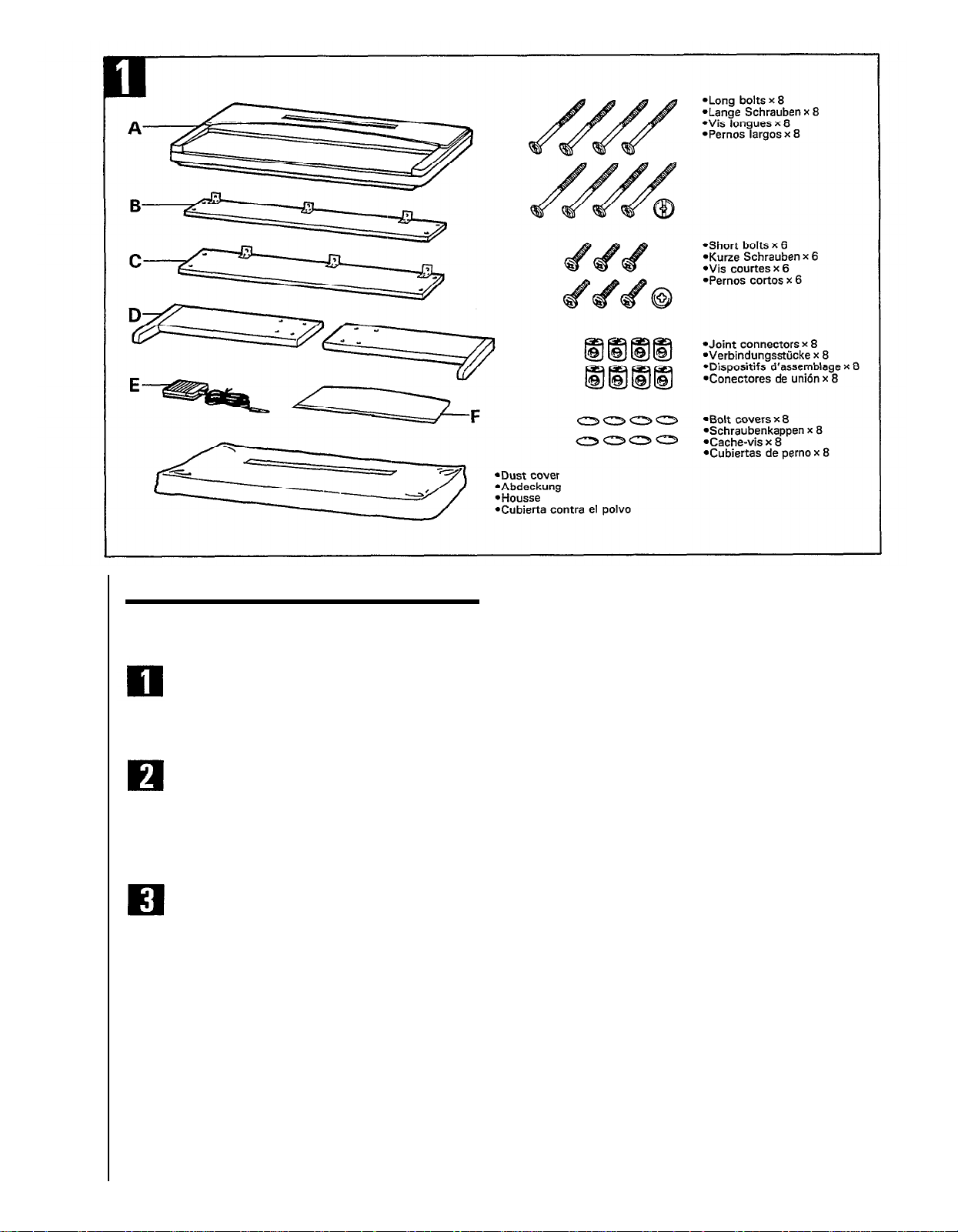
KEYBOARD STAND ASSEMBLY
NOTE: Although the YPP-50 keyboard stand can be assembled
by a single person, the job is much easier with two people.
Open the box and remove all the parts.
On opening the box you should find the parts shown in the
illustration. Check to make sure that all the required parts, are
provided.
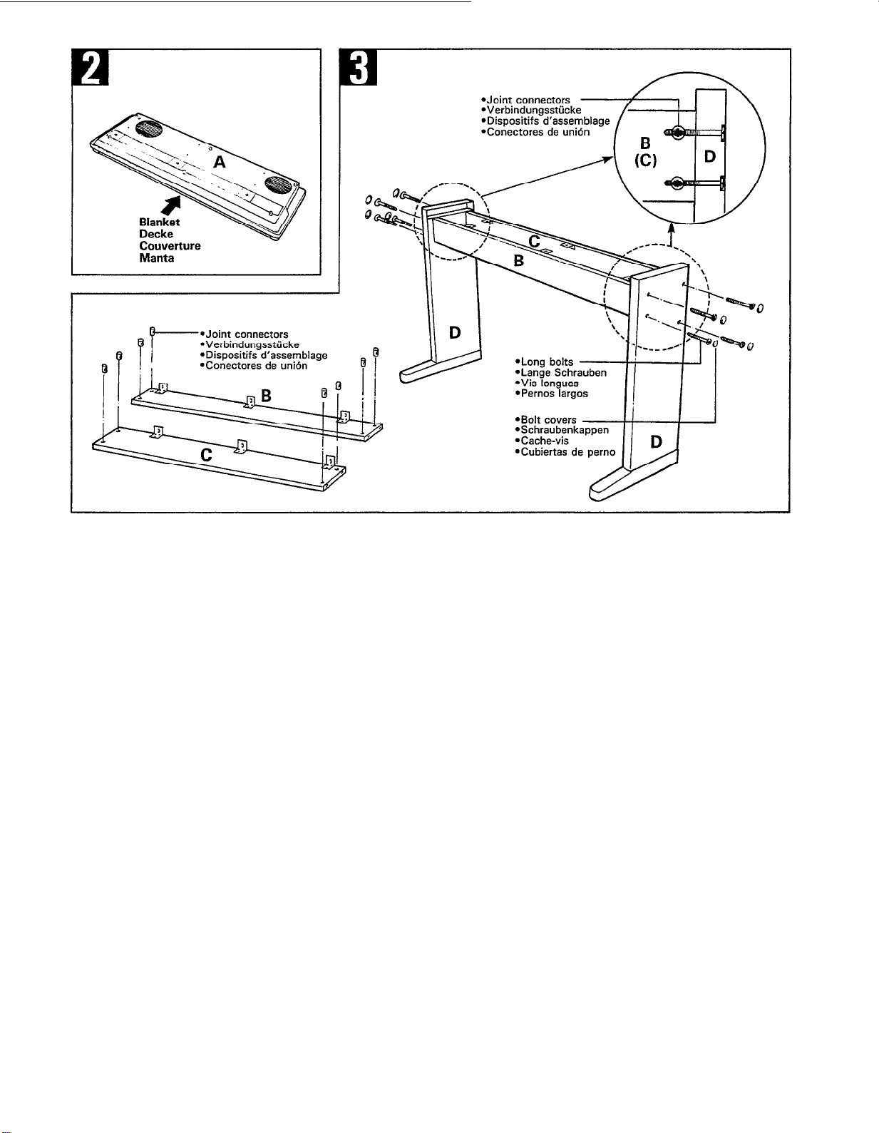
Invert the main unit (A).
When main unit (A) is removed from the box, place it upsidedown on a soft, non-abrasive surface such as a clean rug or
blanket to prevent scratches to the finish. This inverted position makes it easier to attach the assembled keyboard stand
later on.
Attach the side panels (D) to the front (B) and
rear (C) panels.
Begin by installing the joint connectors in the front (B) and rear
(C) panels as shown in the illustration. The front and rear panels
(the rear panel is the wider one) are attached between the side
panels (D) using two long bolts at each end. The sides of the
side panels (D) with the recesses at the top face inwards; the
direction in which the feet extend from the side panels is the
“front” (the direction the keyboard faces). The metal brackets
on the front (B) and rear (C) panels face upwards and inwards.
Attach the first panel loosely so that the second panel slides
into position easily, then attach the second panel and finally
tighten all eight bolts. When the assembly is complete and the
bolts are securely tightened, snap the eight plastic bolt covers
into place over the bolt heads.
l When installing the joint connectors in the holes in the panels,
make sure that the arrows printed on their upper surface face
in the direction shown in the illustration.
2
Page 5
3
Page 6
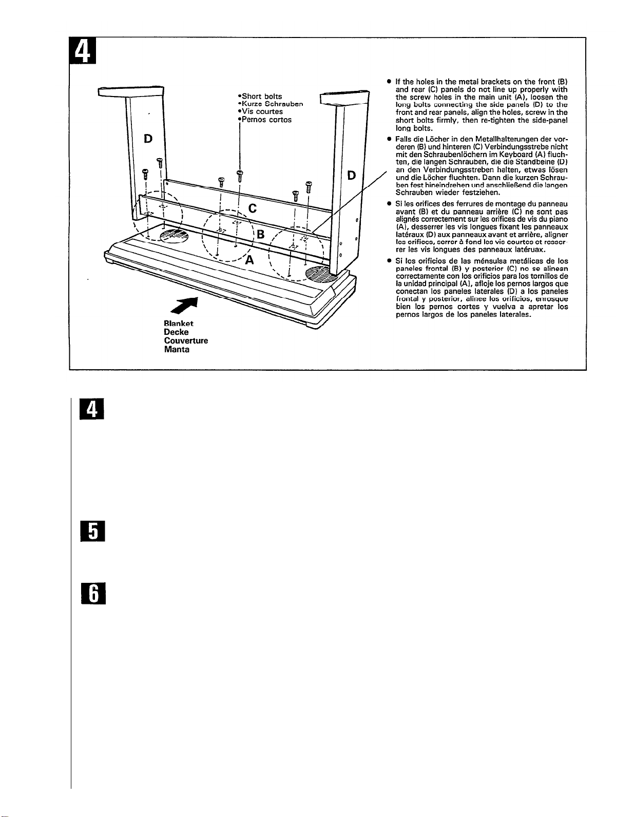
Attach the stand assembly to the main unit (A).
Turn the assembled stand upside down and place it on top of
the main unit (which should also be upside-down) with the feet
extending toward the keyboard side of the main unit. The tops
of the side panels fit into the recessed areas at the ends of the
main unit. Align the holes in the front and rear panel brackets
with the holes in the bottom of the main unit, and firmly screw
in the six short bolts through the brackets. Finally, turn the
entire assembly rightside-up and stand it on its feet.
* Check to make sure that all screws have been securely tightened.
Plug in the damper pedal (E)
Plug the supplied FC5 damper pedal cable into the DAMPER
jack on the rear panel of the main unit, and place the pedal
in a convenient position on the floor below the keyboard.
Install the music stand (F)
Insert the bottom (flat) edge of the music stand (F) into the
slot on the top of the main unit (A) so that the music stand
leans backwards away from the keyboard.
4
Page 7

5
Page 8

TAKING CARE OF YOUR
PERSONAL ELECTRONIC PIANO
Your Personal Electronic Piano is a fine musical instrument,
and deserves the most careful treatment. Observe the following
points and your Personal Electronic Piano will sound and look
great for many years.
1.
Never open the case and touch or tamper with the internal
circuitry.
2.
Always turn the POWER switch OFF after use, and cover
the keyboard with the supplied cover.
3.
Clean the cabinet and keys of your Personal Electronic
Piano only
cleanser may be used if desired. Never use abrasive cleansers,
waxes, solvents or chemical dust cloths since these can dull
or damage the finish.
4.
Never place any vinyl products on your Personal Electronic
Piano. Contact with vinyl can cause irreversible damage to
the finish.
5.
Install your Personal Electronic Piano in a place that is
away from direct sunlight, excessive humidity or heat.
6.
Never apply excessive force to the controls, connectors or
other parts of your Personal Electronic Piano, and avoid
scratching or bumping it with hard objects.
7.
Do not leave heavy objects on the keyboard for an extended
length of time.
8.Never spill water, beverages or other liquids on the keyboard or any other part of the Personal Electronic Piano.
9.
The YPP-50 contains digital circuitry and may cause interference if placed too close to radio receivers, television sets
or similar radio-frequency reception equipment. If such a
problem occurs, move the YPP-50 further away from the
affected equipment.
10.
IMPORTANT!: Check your power supply!
Make sure that your local AC mains voltage matches the
voltage specified on the name plate on the bottom panel. In
some areas a voltage selector may be provided on the rear
panel of the main unit. Make sure that the voltage selector
is set for the voltage in your area.
l
The YPP-50 nameplate is located on the bottom panel.
THE CONTROLS AND
CONNECTORS: BASIC OPERATION
POWER Switch
Press the POWER switch once to turn the power ON, a
second time to turn the power OFF. When the power is
initially turned ON, the PIANO voice selector LED will light.
MASTER VOLUME Control
The MASTER VOLUME control adjusts the volume (level)
of sound produced by the Personal Electronic Piano. The
MASTER VOLUME control also adjusts headphone volume
when a pair of headphones is plugged into the HEADPHONE
jack
MIDI/TRANSPOSE Button
The MIDI/TRANSPOSE button allows access to the Personal
Electronic Piano’s TRANSPOSE function (to shift the pitch
of the entire keyboard up or down) and MIDI functions.
For details refer to the “TRANSPOSITION” and “MIDI
FUNCTIONS” sections on pages 8 and 10, respectively.
with a clean, slightly damp cloth. A neutral
Name Plate Location
METRONOME Button
Press the METRONOME button to start the YPP-50’s builtin metronome. The metronome will sound at either the initial
tempo of 120 beats per minute, or a tempo set using the
TEMPO and
NOME button LED will flash on the first beat of each
measure. Press the METRONOME button a second time to
stop the metronome sound.
l
Metronome Volume:
can be independently adjusted in five steps (normal volume
plus two steps up and two down) by pressing the TEMPO
or
button while holding down the METRONOME
button. The button increases the volume while the
button decreases the volume. Normal volume can be
restored by holding the METRONOME button and pressing both the TEMPO
Note: The metronome is also related to operation of the YPP-50
Performance Memory. This relationship will be described
in the “PERFORMANCE MEMORY” section on page 9.
TEMPO
and Buttons
The TEMPO
the tempo of the YPP-50 metronome. The tempo can be
adjusted from 32 to 280 beats per minute in the following
steps:
32
36
70 72 74 76 78 80 82 84 86 88 90
92 94 96 98 100102104106108110112
114
140144148152156160168176184192200
208
40 44
116
118120122124126128130132136
224232240248256264272280
216
When the power is initially switched ON, the tempo is automatically set to 120. Each brief press on the
increases or decreases the tempo by one step, respectively.
Holding the
crementing or decrementing of the tempo value. The initial
tempo of 120 can be restored at any time by pressing the
TEMPO
Note: The TEMPO and buttons are also used for trans-
and
position and metronome volume control-see“ METRONOME Button” above, and “TRANSPOSITION” on page
8 for details.
buttons, described below. The METRO-
The volume of the metronome sound
and
buttons simultaneously.
and
buttons are mainly used to adjust
48
52
56
60
64
66 68
or button
or
button down causes continuous in-
buttons simultaneously.
6
Page 9

Voice Selectors
The YPP-50 has eight voice selectors. Simply press any of
the voice selectors to select the corresponding voice. The
LED indicator above the voice selector will light to indicate
which voice is currently selected.
l
The Bass Split Mode:
the BASS voice to be played on all keys to the left of
and including the F
on all keys to the right of the F
The YPP-50 Bass Split Mode allows
#
2 key, and any other voice to played
#
2 key. To activate the
Bass Split mode and select the right-hand voice, hold
down the BASS voice selector and press the voice selector
corresponding to the desired right-hand voice, then release
both voice selectors. Both the BASS LED and the LED
of the selected right-hand voice will light. Please note that
the damper pedal does not affect the bass voice in the
Bass Split mode. The Bass Split mode can be disengaged
and the normal voice mode restored by simply pressing
any single voice selector.
Note: The PIANO voice is automatically selected whenever the
POWER switch is initially turned ON.
PERFORMANCE MEMORY REC and PLAY Buttons
These buttons activate the YPP-50 Performance Memory
record and playback functions. Operation of the Performance
Memory is described in detail on page 9.
DEMO Button
Press the DEMO button to hear the YPP-50’s pre-programmed
demonstration. Further details are given on page 8.
HEADPHONE Jack
A standard pair of stereo headphones can be plugged in here
for private practice or late-night playing. The internal speaker
system is automatically shut off when a pair of headphones
is plugged into the HEADPHONE jack.
OPTIONAL IN L/R and OUT L/R Jacks
These jacks are intended primarily for use with Yamaha EMseries Expander Modules such as the EME-1 Reverb Box,
EMT-1 FM Sound Box, EMT-10 AWM Sound Box and
EMR-1 Drum Box. In the case of the EME-1 Reverb Box,
for example, the OPTIONAL OUT jacks connect to the
EME-1 LINE IN jacks, and the EME-1 LINE OUT jacks
connect back to the Personal Electronic Piano OPTIONAL
IN jacks. This allows application of a range of high-quality
digital effects, including reverb and echo, to the Personal
Electronic Piano sound. Refer to the EM-series Expander
Module device owner’s manual for connection details.
DAMPER Jack
The supplied damper pedal (Yamaha FC-5) should be plugged
in here. The damper pedal functions in the same way as a
damper pedal on an acoustic piano. When the damper pedal
is pressed notes played have a long sustain. Releasing the
pedal immediately stops (damps) any sustained notes.
MIDI IN and OUT Connectors
The MIDI IN connector receives MIDI data from anexternal
MIDI device (such as the EMQ-1 Memory Box) which can
be used to control the Personal Electronic Piano. The MIDI
OUT connector transmits MIDI data generated by the Personal Electronic Piano (e.g. note and velocity data produced
by playing the Personal Electronic Piano keyboard).
More details on MIDI are given in “MIDI FUNCTIONS”
on page 10.
7
Page 10

ENJOY THE DEMONSTRATION
2. Initially set the MASTER VOLUME control about three
quarters of the way towards the “MAX” setting. Then, when
you start playing, adjust the VOLUME control for the most
To give you an idea of the YPP-50’s sophisticated capabilities,
comfortable listening level.
it is programmed with a demonstration sequence which plays
automatically while demonstrating some of the instrument’s
voices. Short segments of the following pieces are included:
l 24 Preludes No. 15 in D flat major. “Raindrop” Op.28-15
by Chopin (PIANO voice).
l
The Harmonious Blacksmith by Händel (HARPSI voice).
l
Arabesque by Debussy (PIANO voice).
l
Fugue in G minor by Bach (P.ORGAN voice).
3. Select the desired voice by pressing one of the voice selectors.
1. Press the POWER switch to turn the instrument ON. The
PIANO voice selector LED will light when the power is ON.
4. Play.
2. Slide the MASTER VOLUME control to a position about
Note: The Personal Electronic Piano has “8-note polyphony”
three quarters of the way towards the “MAX” setting. You
can set this control for the most comfortable volume level
after playback begins.
3. The demonstration music will begin playing as soon as you
press the DEMO button.
The demonstration will play continuously, providing samples
of different voices, until the DEMO button is pressed a second
time.
TRANSPOSITION
which means you can play up to 8 notes at once. If you
activate the Bass Split mode, up to two notes can be played
on the lower (bass) section of the keyboard and up to
six notes can be played on the upper fright-hand) section
(see Voice Selectors- The Bass Split Mode” on page
7). The Metronome also uses one note, so up to seven
notes can be played on the keyboard while the metronome
is running (the metronome uses one note of the righthand keyboard section when the Bass Split mode is active).
The Personal Electronic Piano also offers keyboard touch
response, so the volume and timbre of notes played can
be controlled according to how “hard” you play the keys.
The amount of variation available depends on the selected
voice.
l A different voice or tempo can be selected at any time while
the demonstration is playing (refer to the appropriate sections
of this manual for instructions). Voice changes, however, will
only remain in effect until the next automatic voice change.
PLAYING THE PERSONAL
ELECTRONIC PIANO
After making sure that the Personal Electronic Piano’s AC
plug is properly inserted into a convenient AC wall outlet:
1. Press the POWER switch located to the left of the keyboard
to turn the power ON. When the power is turned ON, the
PIANO voice selector LED will light (the PIANO voice is
automatically selected whenever the power is turned ON).
The Personal Electronic Piano’s TRANSPOSE function makes
it possible to shift the pitch of the entire keyboard up or down
in semitone intervals up to a maximum of six semitones. “Transposing” the pitch of the Personal Electronic Piano keyboard
makes it easier to play in difficult key signatures, and you can
simply match the pitch of the keyboard to the range of a singer
or other instrumentalist.
The MIDI/TRANSPOSE button and TEMPO and buttons
are used for transposition.
1. Press and hold the MIDI/TRANSPOSE button.
2. Press the TEMPO or button as many times as necessary
to produce the desired degree of transposition. Each time
the TEMPO or button is pressed the pitch of the keyboard is transposed by one semitone in the specified direction
(i.e. up or down). Pitch can be transposed up or down by
a maximum of six semitones.*
3. Release the MIDI/TRANSPOSE button.
* Pressing both the TEMPO and buttons simultaneously while
the MIDI/TRANSPOSE button is held produces normal keyboard
pitch.
8
Page 11

PITCH CONTROL
Note: Recording can not be activatedif the YPP-60 Multi-Timbre
Mode is engaged (see “The Multi-Timbre Mode” in the
“MIDI FUNCTIONS” section of this manual-page 101.
Pitch control makes it possible to tune the Personal Electronic
Piano over a ±50-cent range in approximately 3-cent intervals.
A hundred “cents” equals one semitone, so the tuning range
provided allows fine tuning of overall pitch over a range of
approximately a semitone. Pitch control is useful for tuning
the Personal Electronic Piano to match other instruments or
recorded music.
Tuning Up
1. To tune up (raise pitch), hold the E
0 and F0 keys simultane-
ously.
2. Press any key between C
3 and B3. Each time a key in this
range is pressed the pitch is increased by approximately 3
cents, up to a maximum of 50 cents above standard pitch.
3. Release the E
Tuning Down
I. To tune down (lower pitch), hold the E
0 and F0 keys.
0
and F
#
0 keys simul-
taneously.
2. Press any key between C
3 and B3. Each time a key in this
range is pressed the pitch is decreased by approximately 3
cents, up to a maximum of 50 cents below standard pitch.
3. Release the E
0 and F#0 keys.
To Restore Standard Pitch*
1.
To restore standard pitch (A3 = 440 Hz), hold the E0, F0 and
F#
0 Tkeys simultaneously.
2. Press any key between C
3. Release the E
* Standard pitch (A3 = 440 Hz) is automatically set whenever the
POWER switch is initially turned ON.
0, F0 and F#0 keys.
3 and B3.
Recording
1. Set the Record Ready Mode
Press the PERFORMANCE MEMORY REC button. This
engages the “record ready” mode: the REC LED will light
and the metronome will sound at the currently selected
tempo.
2. Set the Tempo
Before actually beginning to record, you should select a
tempo that will be easy to record at (using the TEMPO
and/or buttons). If you don’t want to hear the metronome
while recording, press the METRONOME button at this stage
—the metronome sound will stop but the METRONOME
LED will continue flashing at the selected tempo.
3. Start Recording
Recording will begin automatically as soon as you begin
playing.
4. Stop Recording
Press the REC button a second time to stop recording. It is
also possible to stop recording by pressing the PLAY button.
Recording will stop automatically if you exceed the Performance Memory note capacity.
l
Whenever you record using the Performance Memory, any previously recorded material will be erased.
l
The Performance Memory can be erased deliberately as follows:
press the PERFORMANCE MEMORY REC button while holding
down the E
keyboard), release the button and keys, and then press the PERFORMANCE MEMORY REC button one more time to exit the record
mode.
0 and F0 keys (the two lowest white keys on the
Playback
THE PERFORMANCE MEMORY
The YPP-50 Performance Memory functions as a digital recorder that allows you to record and play back anything you play
on the keyboard. You can simply enjoy listening to playback
of your performance, or play along with it on the keyboard.
You can record using any single voice, or using the Bass Split
mode for a combination of left-hand bass and right-hand chords
or melody lines.
l
The Performance Memory records the following data: notes
played, damper pedal operations, voice selection, bass split
mode, the initial tempo and tempo changes made during the
recording.
l
Up to approximately 1300 notes can be recorded in the Performance Memory. This number varies, however, according to
damper-pedal usage and other factors.
l
Material recorded using the Performance Memory will be retained
in the YPP-50 memory for approximately one week even the
power is left OFF the entire time. To keep the recorded performance in memory for longer periods, make sure that the
YPP-50 power is turned ON briefly at least once a week.
1. Press the PLAY Button
Playback of the Performance Memory recording begins as
soon as you press the PERFORMANCE MEMORY PLAY
button (the PLAY button LED will also light).
2. Play Along if You Like
Play along on the YPP-50 keyboard if you like. Please note,
however, that the YPP-50’s eight-note polyphony limitation
still applies. In other words, the total number of notes being
played back by the Performance Memory and those played
on the keyboard cannot exceed eight at any instant.
3. Stop Playback
Playback will stop automatically when the end of the recording is reached. You can also stop playback at any time by
pressing the PLAY or REC button. Playback will also stop
if the DEMO button is pressed or if a MIDI STOP message
is received via the MIDI IN connector.
9
Page 12

MIDI FUNCTIONS
A Brief Introduction to MIDI
MIDI, the Musical Instrument Digital Interface, is a world-
standard communication interface that allows MIDI-compatible
musical instruments and equipment to share musical information
and control one another. This makes it possible to create “systems” of MIDI instruments and equipment that offer far greater
versatility and control than is available with isolated instruments.
For example, most MIDI keyboards (including the Personal
Electronic Piano, of course) transmit note and velocity (touch
response) information via the MIDI OUT connector whenever
a note is played on the keyboard. If the MIDI OUT connector
is connected to the MIDI IN connector of a second keyboard
(synthesizer, etc.) or a tone generator such as the Yamaha
EMT-1 FM Sound Box (essentially a synthesizer with no keyboard), the second keyboard or tone generator will respond
precisely to notes played on the original transmitting keyboard.
The result is that you can effectively play two instruments at
once, providing thick multi-instrument sounds.
This same type of musical information transfer is used for
MIDI sequence recording. A sequence recorder such as the
Yamaha EMQ-1 Memory Box can be used to “record” MIDI
data received from a Personal Electronic Piano, for example.
When the recorded data is played back, the Personal Electronic
Piano automatically “plays” the recorded performance in precise
detail.
The examples given above really only scratch the surface. MIDI
can do much, much more. The YPP-50 offers a number of
MIDI functions that allow it to be used in fairly sophisticated
MIDI systems.
Note: Always use a high-quality MIDI cable to connect MIDI OUT
to MIDI IN terminals. Never use MIDI cables longer than
about 15 meters, since cables longer than this can pick up
noise which can cause data errors.
Program Change Numbers
The YPP-50 transmits a MIDI program number between 0 and
14 when one of its voice selectors is pressed. This normally
causes the correspondingly numbered voice or program to be
selected on a receiving MIDI device. The Personal Electronic
Piano will respond in the same way, automatically selecting
the appropriate voice when a MIDI program change number
is received. See “Program Change ON/OFF” on page 11 for
information on turning program change number reception and
transmission ON or OFF.
NO.
1
Control Change Numbers
Control Change data representing damper pedal operations is
transmitted by the Personal Electronic Piano whenever the pedal
is used. If the receiving device is a tone generator or another
keyboard, it will respond in the same way as the Personal
Electronic Piano’s internal tone generator when these controls
are used. The Personal Electronic Piano also receives and
responds to these as well as some additional control change
data described in the “MIDI DATA FORMAT” section of
this manual. See “Control Change ON/OFF” on page 11 for
information on turning control change number reception and
transmission ON or OFF.
Note: None of the YPP-50 MIDI functions can be engaged while the
VOICE
0
PIANO
E.PIANO
2
HARPSI
3
VIBES
4
5
6
7
BRASS
STRINGS
P.ORGAN
BASS
built-in metronome is running.
NO.
VOICE
8 PIANO + BASS
9
E.PIANO + BASS
HARPSI + BASS
10
VIBES + BASS
11
BRASS + BASS
12
STRINGS + BASS
13
14
P.ORGAN + BASS
—
—
MIDI Transmit & Receive Channel
Selection
The MIDI system allows transmission and reception of MIDI
data on 16 different channels. Multiple channels have been
implemented to allow selective control of certain instruments
or devices connected in series. For example, a single MIDI
sequence recorder could be used to “play” two different instruments or tone generators. One of the instruments or tone generators could be set to receive only on channel 1, while the other
is set to receive on channel 2. In this situation the first instrument or tone generator will respond only to channel-l information transmitted by the sequence recorder, while the second
instrument or tone generator will respond only to channel-2
information. This allows the sequence recorder to “play” two
completely different parts on the receiving instruments or tone
generators.
MIDI “Messages” Transmitted & Received by the Personal Electronic Piano ___
The MIDI information (messages) transmitted and received by
the YPP-50 Personal Electronic Piano are as follows:
Note and Velocity Data
This information tells the receiving keyboard or tone generator
to play a certain note (specified by the MIDI note number) at
a certain dynamic level (specified by the MIDI velocity value).
Note and velocity data is transmitted by the Personal Electronic
Piano whenever a key is pressed, and the Personal Electronic
Piano’s internal AWM tone generator will “play” the cor-
responding note(s) whenever note and velocity data is received
from an external MID1 device.
10
In any MIDI control setup, the MIDI channels of the transmitting and receiving equipment must be matched for proper
data transfer. An “OMNI” receive mode is also available,
which allows reception on all 16 MlDI channels. In the OMNI
mode it is not necessary to match the receive channel of the
receiving device to the the transmit channel of the transmitting
device (except when receiving mode messages).
Page 13

Setting the Personal Electronic Piano MIDI Channels
1. Press and hold the MIDI/TRANSPOSE button.
2. Press the key on the keyboard corresponding to the desired
MIDI transmit or receive channel.*
3. Release the MIDI/TRANSPOSE button.
* Keys C1 through D#2 on the keyboard are used to set the MIDI
transmit channel, and keys C
OMNI mode OFF and set the MIDI receive channel as shown in
the illustration below. The E
and basic receive channel 1.
Note: When the power is initially turned ON, MIDI receive is set
to the OMNI mode and the transmit channel is set to 1.
3 through D#4 are used to turn the
4 key sets the OMNI receive mode
MIDI FUNCTION CHART
Function
Local ON/OFF
Program Change ON/OFF
Control Change ON/OFF
Multi-Timbre Mode
Split & Left Local OFF
Split & Right Local OFF
Panel Data Transmit P.ORGAN
l The MIDI functions listed above are engaged by holding down the
MIDI/TRANSPOSE button and pressing the corresponding voice
selector. Full details are given in the following pages.
Voice Selector*
PIANO
E.PIANO
HARPSI
VIBES
STRINGS
BRASS
Local Control ON/OFF
“Local Control” refers to the fact that, normally, the Personal
Electronic Piano keyboard controls its internal tone generator,
allowing the internal voices to be played directly from the keyboard. This situation is “Local Control ON” since the internal
tone generator is controlled locally by its own keyboard.
Local control can be turned OFF, however, so that the Personal
Electronic Piano keyboard does not
but the appropriate MIDI information is still transmitted via
the MIDI OUT connector when notes are played on the key-
board. At the same time, the internal tone generator responds
to MIDI information received via the MIDI IN connector. This
means that while an external MIDI sequence recorder such as
the Yamaha EMQ-1 Memory Box, for example, plays the Personal Electronic Piano’s internal voices, an external tone generator such as the EMT-l can be played from the Personal Elec-
tronic Piano keyboard.
play the internal voices,
Turning Local Control ON or OFF
1.
Hold down the MIDI/TRANSPOSE button.
2.
Press the PIANO voice selector. If the PIANO LED is lit
when the PIANO voice selector is pressed; you have turned
local control OFF. If the PIANO LED is not lit when the
PIANO voice selector is pressed, you have turned local control ON.
3.
Release the MIDI/TRANSPOSE button.
Program Change ON/OFF
Normally the Personal Electronic Piano will respond to MIDI
program change numbers received from an external keyboard
or other MIDI device, causing the correspondingly numbered
Personal Electronic Piano voice to be selected. The Personal
Electronic Piano will normally also send a MIDI program change
number whenever one of its voices is selected, causing the correspondingly numbered voice or program to be selected on the
external MIDI device if the device is set up to receive and respond to MIDI program change numbers.
This function makes it possible to cancel program change number
reception and transmission so that voices can be selected on
the Personal Electronic Piano without affecting the external
MIDI device, and vice versa.
1.Hold down the MIDI/TRANSPOSE button.
2.
Press the E.PIANO voice selector. If the E.PIANO LED is
lit when the E.PIANO voice selector is pressed, you have
turned program change reception/transmission OFF. If the
E.PIANO LED is not lit when the E.PIANO voice selector
is pressed, you have turned program change reception/transmission ON.
3.
Release the MIDI/TRANSPOSE button.
Control Change ON/OFF
Normally the Personal Electronic Piano will respond to MIDI
control change data received from an external MIDI device or
keyboard, causing the selected Personal Electronic Piano voice
to be affected by pedal and other “control” settings received
from the controlling device. The Personal Electronic Piano also
transmits MIDI control change information when either of its
pedals are operated.
This function makes it possible to cancel control change data
reception and transmission if you do not want the Personal
Electronic Piano voices to be affected by control change data
received from an external device or vice versa.
1.
Hold down the MIDI/TRANSPOSE button.
2.
Press the HARPSI voice selector. If the HARPSI LED is
lit when the HARPSI voice selector is pressed, you have
turned control change reception/transmission OFF. If the
HARPSI LED is not lit when the HARPSI voice selector is
pressed, you have turned control change reception/transmission ON.
3.
Release the MIDI/TRANSPOSE button.
11
Page 14

The Multi-Timbre Mode
The Multi-Timbre mode is a special mode in which the Personal
Electronic Piano voices can be independently controlled on
different MIDI channel numbers (1 through 10) by an external
MIDI device such as the Yamaha EMQ-1 Memory Box.
CHAN. VOICE
1 PIANO 6
2
3
4 VIBES 9 PIANO
5 BRASS
The Multi-Timbre mode can be activated as follows:
1.
Hold down the MIDI/TRANSPOSE button.
2. Press the VIBES voice selector. If the VIBES LED is lit when
the VIBES voice selector is pressed, you have turned the
Multi-Timbre mode ON. If the VIBES LED is not lit when
the VIBES voice selector is pressed, you have turned the
Multi-Timbre mode OFF.
3.
Release the MIDI/TRANSPOSE button.
Here’s an example of how you could
mode to record three different parts on the EMQ-1 Memory
Box that will play different voices on the Personal Electronic
Piano when played back.
1. Connect the EMQ-1 to the Personal Electronic Piano as
2. Select the first voice and MIDI transmit channel number,
then record the first part on the EMQ-1.
3. Activate the Personal Electronic Piano Multi-Timbre mode,
then select a new MIDI transmit channel and voice and record
the second part on the EMQ-1 using its overdubbing function.
4. While still in the Multi-Timbre mode, select the third MIDI
transmit channel and voice and record the third part on the
EMQ-1 using its overdubbing function.
5. Still in the Multi-Timbre mode, play back the EMQ-1. The
recorded parts will be played back using the individual voices
selected during recording, providing a full ensemble sound.
E.PIANO
HARPSI
shown below.
CHAN.
7
8
10
VOICE
STRINGS
P.ORGAN
BASS
PIANO
use the Multi-Timbre
The Split & Left Local OFF Mode
In the split mode one section of the Personal Electronic Piano
keyboard is used to play a Personal Electronic Piano voice in
the normal way, while the remaining section is used to play a
second MIDI keyboard or tone generator such as the Yamaha
EMT-1 FM Sound Box or EMT-10 AWM Sound Box. In this
mode the right-hand section of the keyboard is used to play
an internal Personal Electronic Piano voice, while the left-hand
section of the keyboard plays the external keyboard or tone
generator. Playing the left-hand section of the keyboard produces no sound from the Personal Electronic Piano. The “split
point,”
of the keyboard, is automatically set at F#
The split mode is useful if, for example, you want to play a
piano (Personal Electronic Piano) voice with the right hand
while playing a synthesizer bass line or string section with the
left hand.
When the split mode is activated, notes played on the lefthand section are transmitted via the Personal Electronic Piano
MIDI OUT connector on MIDI channel 2. Notes played on the
right-hand section are transmitted on the “basic channel” (i.e.
the channel set using the MIDI channel selection function described previously). Damper pedal data is sent via both channels.
or the key that divides the left- and right-hand sections
2.
Activating the Split & Left Local OFF Mode
1.
Hold down the MIDI/TRANSPOSE button.
2.
Press the STRINGS voice selector. If the STRINGS LED is
lit when the STRINGS voice selector is pressed, you have
turned the Split & Left Local OFF mode ON. If the STRINGS
LED is not tit when the STRINGS voice selector is pressed,
you have turned the Split & Left Local OFF mode OFF.
3.
Release the MIDI/TRANSPOSE button.
The Split & Right Local Off Mode
In the YPP-50 either the right- or left-hand section of the keyboard can be assigned to control an external keyboard or tone
generator. Assigning the left-hand section to external tone generator control was described in the previous section. To assign
the right-hand section to external tone generator control while
playing the Personal Electronic Piano voices with the left hand,
press the BRASS voice selector instead of the STRINGS voice
selector when activating the Split mode (See “Activating the
Split & Left Local OFF Mode” in the previous section). All
other operations are exactly the same as described in the previous section.
Transmitting the Panel Settings
This function causes all the current Personal Electronic Piano
control settings (selected voice, etc) to be transmitted via the
MIDI OUT terminal. This is particularly useful if you will be
recording performances to a MIDI sequence recorder* which
will be used to control the Personal Electronic Piano on playback. By transmitting the Personal Electronic Piano panel settings and recording them on the MIDI sequence recorder prior
to the actual performance data, the Personal Electronic Piano
will be automatically restored to the same settings when the
performance is played back.
The Yamaha EMQ-1 Memory Box automatically receives and
*
records the Personal Electronic Piano panel settings when a recording is begun, so this function is most useful with MIDI sequence
recorders other
1.
Hold down the MIDI/TRANSPOSE button.
2.
Press the P.ORGAN voice selector.
3.
Release the MIDI/TRANSPOSE button.
than the EMQ-1.
12
Page 15

TROUBLESHOOTING
MIDI DATA FORMAT
If you encounter what appears to be a malfunction, please check
the following points before assuming that your Personal Electronic Piano is faulty.
1. No Sound When the Power is Turned ON
Is the AC plug properly connected to an AC wall outlet?
Check the AC connection carefully. Is the MASTER VOLUME
control turned up to a reasonable listening level?
2. The Personal Electronic Piano Reproduces Radio or TV
Sound
This can occur if there is a high-power transmitter in your
vicinity. Contact your Yamaha dealer.
3. Intermittent Static Noise
This is usually due to turning ON or OFF a household appliance or other electronic equipment which is fed by the same
AC mains line as your Personal Electronic Piano.
4. Interference Appears On Radio or TV Sets Located Near
the Personal Electronic Piano
The Personal Electronic Piano contains digital circuitry which
can generate radio-frequency noise. The solution is to move
the Personal Electronic Piano further away from the affected
equipment, or vice versa.
5. Distorted Sound When the Personal Electronic Piano is Connected to An External Amplifier/Speaker System
If the Personal Electronic Piano is connected to a stereo
system or instrument amplifier and the sound is distorted,
reduce the setting of the Personal Electronic Piano volume
control to a level at which the distortion ceases.
OPTIONS & EXPANDER MODULES
OPTIONS
BC-7 Bench
A stable, comfortable bench styled to match your Yamaha
Personal Electronic Piano.
HPEd Stereo Headphones
High-performance lightweight dynamic headphones with extrasoft ear pads.
PCS-3 Connecting Cord
For connecting the Personal Electronic Piano to a stereo system
or other audio equipment.
EXPANDER MODULES
Sound Box EMT-10
Sound Box EMT-1
Memory Box EMQ-1
Drum Box EMR-1
Reverb Box EME-1
These state-of-the-art Expander Modules can dramatically expand
the musical scope of your Personal Electronic Piano.
NOTE: Some items may not be available in certain areas.
.........................
............................
........................
..............................
...........................
AWM Sound Expander
FM Sound Expander
Disk Recorder
Digital Drummer
Digital Reverb
If you’re already very familiar with MIDI, or are using a computer to control your music hardware with computer-generated
MIDI messages, the data provided in this section can help you
to control the Personal Electronic Piano.
1. NOTE ON/OFF
Data format: [9nH]–›[kk]–›[vv]
9nH = Note ON/OFF event (n = channel number)
kk = Note number (28~103=E
vv = Velocity (Key ON = 1~127. Key OFF= 0)
* Note OFF event format [8nH]–›[kk] also recognized (reception
2. CONTROL CHANGE & MODE MESSAGES
Data format: [BnH]–›[cc]–›[dd]
BnH = Control event (n = channel number)
cc = Control number (or mode message number)
dd = Control value
cc
07H
0BH
40H
43H
79H
7AH
7BH All notes OFF
7CH OMNI OFF/All
7DH OMNI ON/All
* 43H, 79H, 7AH, 7BH, 7CH and 7DH are receive only.
3.
PROGRAM CHANGE
Data format: [CnH]–›[dd]
CnH = program event (n = channel number)
dd = Program number
dd
00H
0lH E.PIANO
02H HARPSI 0AH
03H VIBES
04H BRASS
05H STRINGS
06H
07H
* No voice change is made when dd>0EH.
4.
SYSTEM REALTIME MESSAGES
Active Sensing (FEH)
Transmitted every 200 milliseconds. If not received for more than 400
milliseconds a NOTE OFF occurs.
5.
SYSTEM EXCLUSIVE MESSAGES
Data format:
x=0, ff=7CH: Panel data dump. Panel data follows 7CH.
x=2, ff=7CH: Panel data request transmission.
Data format:
43H = YAMAHA ID
73H = SINGLE KEYBOARD ID
20H = YPP-50 ID
nn = 40H: Performance play ON (receive only)
nn = 41H: Performance play OFF (receive only)
nn = 50H: Tempo UP
nn = 51H: Tempo DOWN
nn = 52H: Tempo 120
6.
MULTI TIMBRE MODE
Data format:
43H = YAMAHA ID
73H = SINGLE KEYBOARD ID
id=0lH (Standard), 1BH (Clavinova), or 20H (YPP-50)
nn=15H: MULTI TIMBRE mode ON; nn=13H: MULTI TIMBRE
mode OFF; nn=7nH: Receive channel change (n = channel number.
Receive only).
* All MIDI data available for general use are given above.
only).
PARAMETER
Volume
Expression
Damper pedal
Soft pedal
Reset all controllers
Local ON/OFF
notes OFF
notes OFF
VOICE
PIANO
P.ORGAN
BASS
0
~ G
6)
dd
0=OFF; 6FH=-3dB; 7FH=0dB
0=OFF; 6FH=-3dB; 7FH=0dB
0~3FH=OFF; 40H~7FH=ON
0~3FH=OFF; 40H~7FH=ON
0
0=OFF; 7FH=ON
0
0
0
dd
VOICE
08H PIANO + BASS
E.PIANO + BASS
09H
HARPS1 + BASS
0BH VIBES + BASS
0CH BRASS + BASS
0DH STRINGS + BASS
0EH P.ORGAN + BASS
[F0H]–›[43H]–›[xn]–›[ff]..................... [F7H]
[F0H]–›[43H]–›[73H]–›[20H]–›[nn]–›[F7H]
[F0H]–›[43H]–›[73H]–›[id]–›[nn]–›[F7H]
13
Page 16

SPECIFICATIONS
KEYBOARD
VOICE SELECTORS
OTHER CONTROLS
JACKS/CONNECTORS
INPUT & OUTPUT
LEVEL/IMPEDANCE
MAIN AMPLIFIER
SPEAKERS
76 KEYS (E0~G
PIANO, E.PIANO, HARPSICHORD, VIBES, STRINGS, BRASS, P.ORGAN, BASS
MASTER VOLUME, MIDI/TRANSPOSE, METRONOME, TEMPO
PERFORMANCE MEMORY REC/PLAY, DEMO
HEADPHONES, OPTIONAL IN L/R, OPTIONAL OUT L/R, MIDI IN/OUT, DAMPER
OPTIONAL OUT: 600
OPTIONAL IN: 22 k/–10 dBm (for nominal output level)
10 Watts
16 cm (6-2/7”) x 2
* Specifications subject to change without notice.
YPP-50
6)
/1~4 Vpp
DIMENSIONS (W x H x D)
WEIGHT
1157 x 396 x 759 mm (45-6/9” x 15-3/5” x 28-8/9”)
23 kg (50-5/7 lbs.)
Page 17

YAMAHA [ Personal Electronic Piano ]
Model YPP50 MIDI Implementation Chart
Date : 7/28, 1989
Version : 1.0
Function
Basic
Channel
Default
Changed
Default
Mode
Messages
Note
Number
True Voice
Velocity Note on
Note off
After
Touch
Key's
Ch's
Pitch Bender
07
Control
11
64 O
Change
Transmitted
1
1–16
3
X
**************
28-103
**************
9nH, v=1-127 O
O
9nH, v=0
X
X
X
X
X
X
Recognized
1
1-16
1
OMNIon, OMNIoff
X
28-103
28-103
X
X
X
X
O
O
O
Remarks
v=1-127
Volume
Expression
Damper
67
121
Program
Change
: True
#
System Exclusive
System
Song Pos
Song Sel
Common
System
Real Time
Aux
Tune
Clock
Commands X
Local ON/OFF
All Notes OFF
Mes-
sages
Active Sense
Reset
X
X
O
0-14
*************
O
X X
X
X
X
X
X
O O
X
Notes : *1 = receive (123) if omni off or multi-timdre on
O
O
Soft Pedal
Reset All
Controllers
O
0-14
0-14
O
X
X
X
X
O
O
(123-125) *1
X
Mode 1
Mode 3
OMNION,
OFF,
OMNI
POLY
POLY
Mode 2
Mode 4
OMNI
OMNI
ON,
MONO
MONO
OFF,
O
X
Yes
No
Page 18

FCC INFORMATION (USA)
While the following statements are provided to comply with FCC Regulations in the United States, the corrective measures listed
are applicable worldwide.
This series of Yamaha Personal Electronic Piano uses frequencies that appear in the radio frequency range, and if installed in
the immediate proximity of some types of audio or video devices within three meters (approximately ten feet), interference may
occur.
This series of Yamaha Personal Electronic Piano has been type-tested, and found to comply with the specifications set for a
class B computer in accordance with those specifications listed in sub-part J, part 15 of the FCC rules. These rules are designed
to provide a reasonable measure of protection against such interference. However, this does not guarantee that interference
will not occur.
If your Personal Electronic Piano should be suspected of causing interference with other electronic devices, verification can
be made by turning your Personal Electronic Piano off and on. If the interference continues when your Personal Electronic Piano
is off, the Personal Electronic Piano is not the source of the interference. If your Personal Electronic Piano does appear to be
the source of the interference, you should try to correct the situation by using one or more of the following measures:
l
Relocate either the Personal Electronic Piano or the electronic device that is being affected by the interference.
l Utilize power outlets for the Personal Electronic Piano and the device being affected that are on different branch (circuit
breaker or fuse) circuits, or install a/c line filters.
l
In the case of radio-TV interference, relocate the antenna or, if the antenna lead-in is a 300 ohm ribbon lead, change the lead-in
to coaxial type cable.
If these corrective measures do not produce satisfactory results, please contact a Yamaha dealer for suggestions and/or
corrective measures. If you can not locate a Yamaha dealer in your general area, please contact the Service Division, Yamaha
Corporation of America, 6600 Orangethorpe Ave., Buena Park, CA 90620, U.S.A.
If for any reason, you should need additional information relating to radio or TV interference, you may find a booklet prepared
by the Federal Communications Commission helpful: “How to Identify and Resolve radio-TV Interference Problems.” This booklet
Stock #004-000-00345-4, is available from the U.S. Government Printing Office, Washington D.C. 20402.
* This applies only to products distributed by YAMAHA CORPORATION OF AMERICA
CANADA
THIS DIGITAL APPARATUS DOES NOT EXCEED THE “CLASS B”
LIMITS FOR RADIO NOISE EMISSIONS FROM DIGITAL APPARATUS
SET OUT IN THE RADIO INTERFERENCE REGULATION OF THE
CANADIAN DEPARTMENT OF COMMUNICATIONS.
l This applies only to products distributed by Yamaha Canada Music Ltd.
Page 19

YAMAHA
YAMAHA
P.O. Box 1, Hamamatsu, Japan
CORPORATlON
909 VI27370 Printed in Japan
 Loading...