

Yamaha YP250R (2005) Service Manual

2005
YP250R
SERVICE MANUAL
1C0-F8197-E0

EAS00000
YP250R 2005
SERVICE MANUAL
©2007 by Yamaha Motor España, S.A.
First edition, February 2007
All rights reserved.
Any reproduction or unauthorized use
without the written permission of
Yamaha Motor España, S.A.
is expressly prohibited.
EAS00002
NOTICE
This manual was produced by the Yamaha Motor España S.A. primarily for use by Yamaha dealers
and their qualified mechanics. It is not possible to include all the knowledge of a mechanic in one
manual. Therefore, anyone who uses this book to perform maintenance and repairs on Yamaha
vehicles should have a basic understanding of mechanics and the techniques to repair these types
of vehicles. Repair and maintenance work attempted by anyone without this knowledge is likely to
render the vehicle unsafe and unfit for use.
Yamaha Motor España S.A. is continually striving to improve all of its models. Modifications and significant changes in specifications or procedures will be forwarded to all authorized Yamaha dealers
and will appear in future editions of this manual where applicable.
NOTE:
_
Designs and specifications are subject to change without notice.
EAS00005
IMPORTANT MANUAL INFORMATION
Particularly important information is distinguished in this manual by the following.
The Safety Alert Symbol means ATTENTION! BECOME ALERT! YOUR
SAFETY IS INVOLVED!
WARNING
CAUTION:
NOTE:
Failure to follow WARNING instructions could result in severe injury or death
the vehicle operator, a bystander or a person checking or repairing the vehicle.
A CAUTION indicates special precautions that must be taken to avoid damage
to the vehicle.
A NOTE provides key information to make procedures easier or clearer.
to
EAS00007
HOW TO USE THIS MANUAL
This manual is intended as a handy, easy-to-read reference book for the mechanic. Comprehensive
explanations of all installation, removal, disassembly, assembly, repair and check procedures are
laid out with the individual steps in sequential order.
1
The manual is divided into chapters. An abbreviation and symbol in the upper right corner of
each page indicate the current chapter.
Refer to “SYMBOLS”.
2
Each chapter is divided into sections. The current section title is shown at the top of each page,
except in Chapter 3 (“PERIODIC CHECKS AND ADJUSTMENTS”), where the sub-section
title(s) appears.
3
Sub-section titles appear in smaller print than the section title.
4
To help identify parts and clarify procedure steps, there are exploded diagrams at the start of
each removal and disassembly section.
5
Numbers are given in the order of the jobs in the exploded diagram. A circled number indicates a
disassembly step.
6
Symbols indicate parts to be lubricated or replaced.
Refer to “SYMBOLS”.
7
A job instruction chart accompanies the exploded diagram, providing the order of jobs, names of
parts, notes in jobs, etc.
8
Jobs requiring more information (such as special tools and technical data) are described sequentially.
12
GEN
SPEC
INFO
34
CHK
CHAS
ADJ
56
ENG
78
COOL
EAS00008
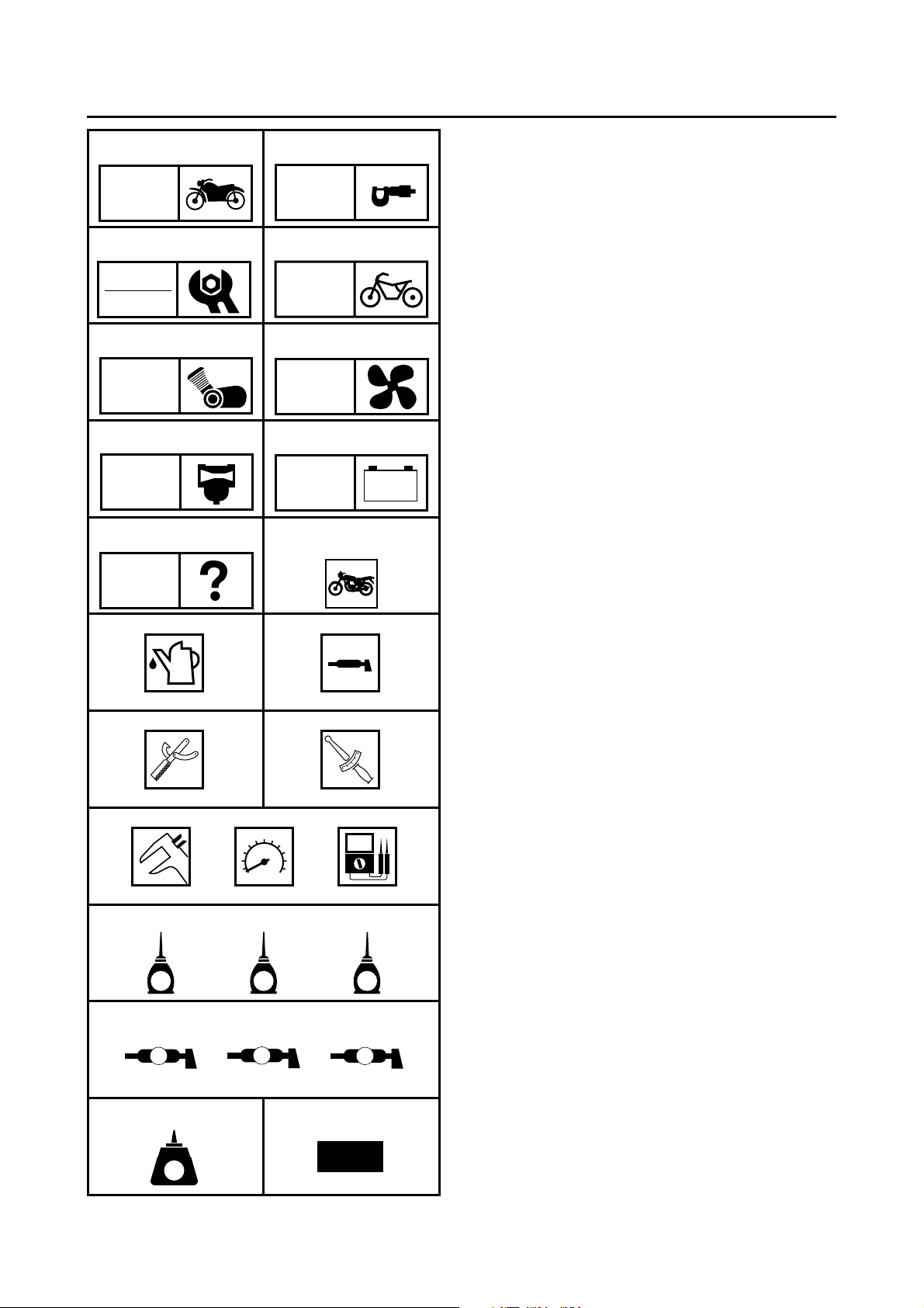
SYMBOLS
The following symbols are not relevant to
every vehicle.
Symbols 1 to 9 indicate the subject of each
chapter.
General information
1
Specifications
2
Periodic checks and adjustments
3
Chassis
4
Engine
5
Cooling system
6
Carburetor
7
Electrical system
8
Troubleshooting
9
CARB
90
ELEC
– +
TRBL
SHTG
AB
CD
T
.
R
.
EFG
HIJ
LS
G
M
M
E
KLM
B
Symbols 0 to G indicate the following.
Serviceable with engine mounted
0
Filling fluid
A
Lubricant
B
Special tool
C
Tightening torque
D
Wear limit, clearance
E
Engine speed
F
Electrical data
G
Symbols H to M in the exploded diagrams
indicate the types of lubricants and lubrication
points.
Engine oil
H
Gear oil
I
Molybdenum-disulfide oil
J
Wheel-bearing grease
K
Lithium-soap- based grease
L
Molybdenum-disulfide grease
M
NO
LT
New
Symbols N to O in the exploded diagrams
indicate the following.
Apply locking agent (LOCTITE
N
Replace the part
O
®
)

EAS00010
– +
TABLE OF CONTENTS
GENERAL INFORMATION
SPECIFICATIONS
PERIODIC CHECKS AND
ADJUSTMENTS
CHASSIS
ENGINE
GEN
INFO
SPEC
CHK
ADJ
CHAS
ENG
1
2
3
4
5
COOLING SYSTEM
CARBURETOR
ELECTRICAL SYSTEM
TROUBLESHOOTING
COOL
CARB
ELEC
TRBL
SHTG
6
7
8
9

CHAPTER 1
GENERAL INFORMATION
GEN
INFO
IDENTIFICATION
VEHICLE IDENTIFICATION NUMBER .....................................................1-1
MODEL LABEL..........................................................................................1-1
MULTI-FUNCTION DISPLAY
IMPORTANT INFORMATION
PREPARATION FOR REMOVAL AND DISASSEMBLY........................... 1-5
REPLACEMENT PARTS...........................................................................1-5
GASKETS, OIL SEALS AND O-RINGS .................................................... 1-5
LOCK WASHERS/PLATES AND COTTER PINS .....................................1-6
BEARINGS AND OIL SEALS....................................................................1-6
CIRCLIPS..................................................................................................1-6
CHECKING THE CONNECTIONS
SPECIAL TOOLS
............................................................................................1-1
..........................................................................1-2
.........................................................................1-5
..................................................................1-7
............................................................................................1-8
1
1
GEN
IDENTIFICATION
EAS00015
GENERAL INFORMATION
IDENTIFICATION
EAS00017
VEHICLE IDENTIFICATION NUMBER
The vehicle identification number 1 is
stamped into the frame.
EAS00018
MODEL LABEL
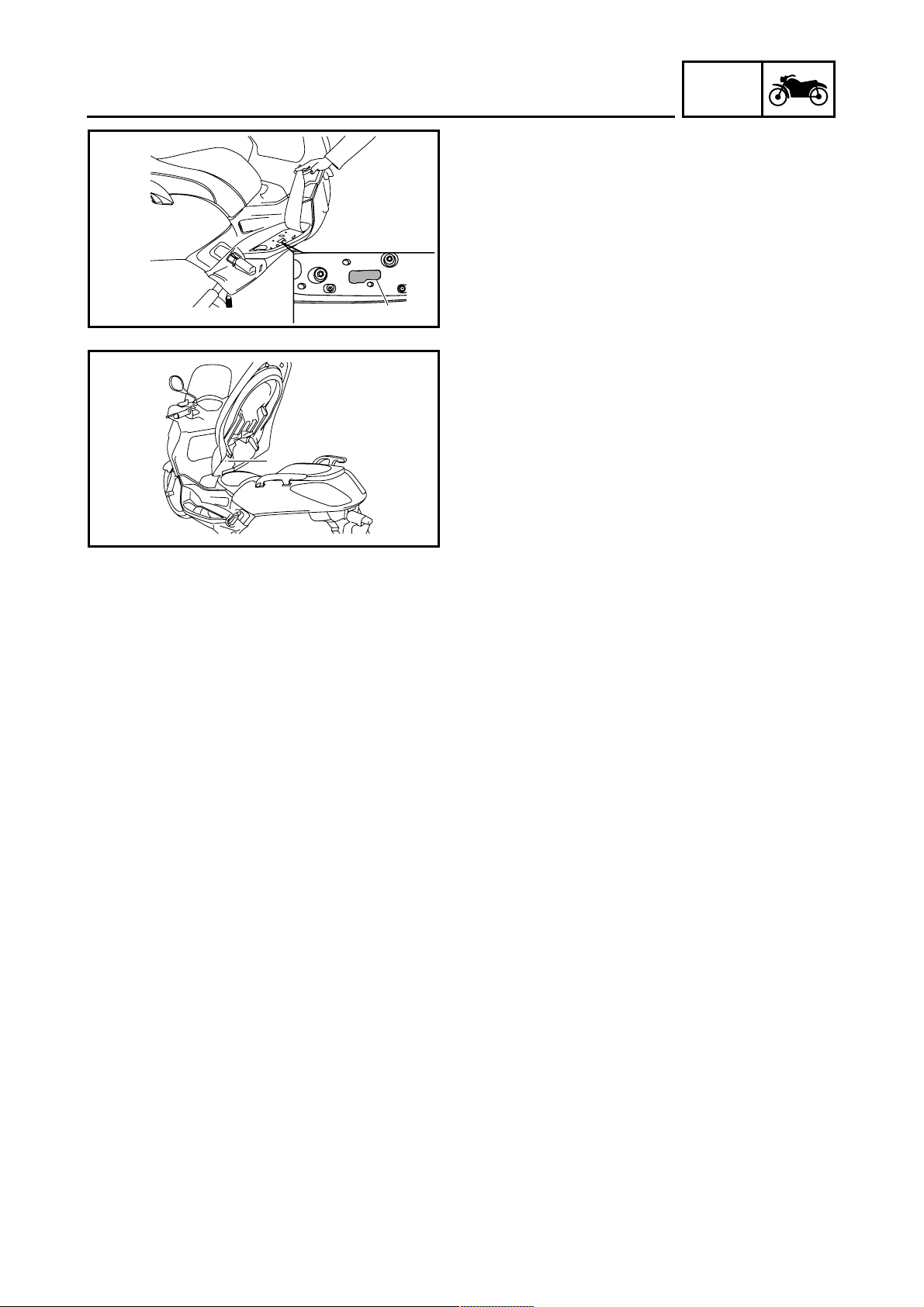
The model label 1 is affixed underneath the
seat. This information will be needed when
ordering spare parts.
INFO
1 - 1
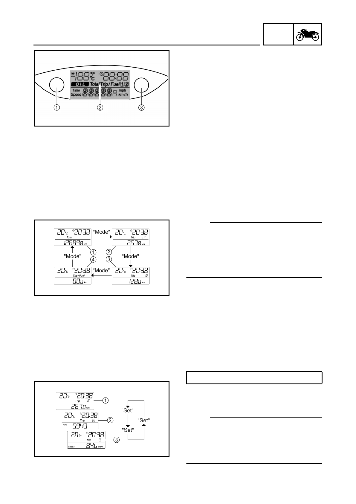
MULTI-FUNCTION DISPLAY
MULTI-FUNCTION DISPLAY
The multi-function display is equipped with the
following:
• an odometer (which shows the total distance traveled)
• two tripmeters (which show the distance
traveled since they were last set to zero, the
time passed since the tripmeters were set
to zero, and the average speed traveled
during this time)
“MODE” button
1
Multi-function display
2
“SET” button
3
• a fuel reserve tripmeter (which shows the
distance traveled since the fuel level warning light came on)
• a clock
• an ambient temperature display
• an oil change indicator (which comes on
when the engine oil should be changed)
GEN
INFO
NOTE:
• For the UK, the distance traveled is displayed in miles and the temperature reading
is displayed in °F.
• For other countries, the distance traveled is
displayed in kilometers and the temperature
reading is displayed in °C.
Total
1
Trip 1
2
Trip 2
3
Trip/Fuel
4
Odometer and tripmeter modes
Pushing the “MODE” button switches the display between the odometer mode “Total” and
the tripmeter modes “Trip” in the following
order:
Total → Trip 1 → Trip 2 → Trip/fuel → Total
Distance
1
Time
2
Average speed
3
NOTE:
• The Trip/fuel odometer is only activated if the
fuel level warning light comes on.
• The Trip 2 odometer is automatically reset
after turning the key to “OFF” and two hours
have passed.
1 - 2
MULTI-FUNCTION DISPLAY
Pushing the “SET” button when in the tripmeter mode switches the display between the different tripmeter functions in the following
order:
Distance → Time → Average speed → Distance
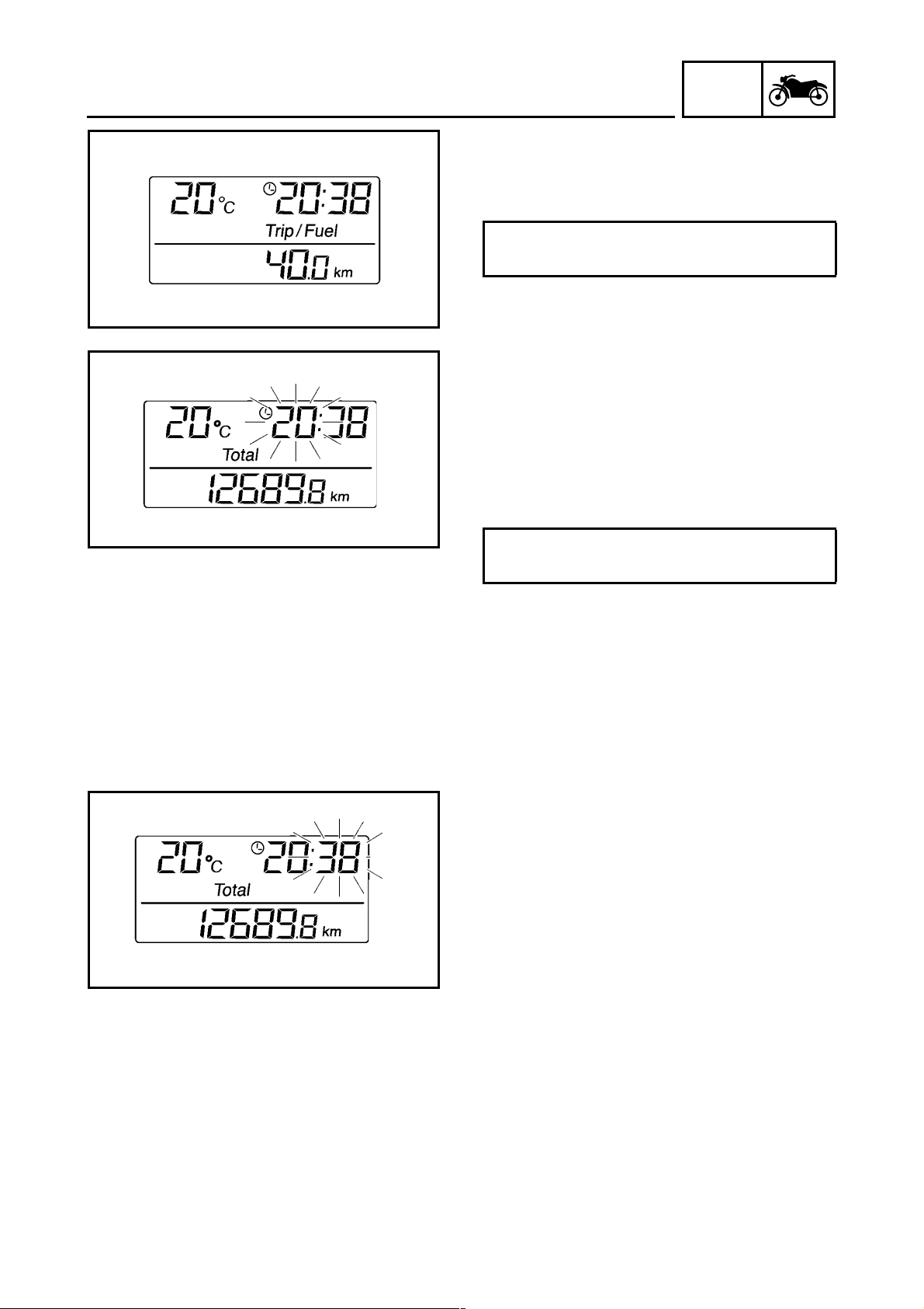
If the fuel level warning light comes on, the display will automatically change to the fuel
reserve tripmeter mode “Trip/fuel” and start
counting the distance traveled from that point.
In that case, pushing the “MODE” button
switches the display between the various tripmeter and odometer modes in the following
order:
GEN
INFO
Trip/Fuel → Trip 1 → Trip 2 → Total → Trip/
fuel
To reset a tripmeter, select it by pushing the
“MODE” button, and then push the “SET” button for at least one second. If you do not reset
the fuel reserve tripmeter manually, it will reset
itself automatically and the display will return
to the prior mode after refueling and traveling 5
km.
Clock mode
To set the clock:
1. When the display is in the “To t a l ” mode,
push the “SET” button for at least two seconds.
2. When the hour digits start flashing, push
the “SET” button to set the hours.
3. Push the “MODE” button, and the minute
digits will start flashing.
4. Push the “SET” button to set the minutes.
5. Push the “MODE” button and then release it
to start the clock. The display will return to
the “To t a l ” mode.
1 - 3
MULTI-FUNCTION DISPLAY
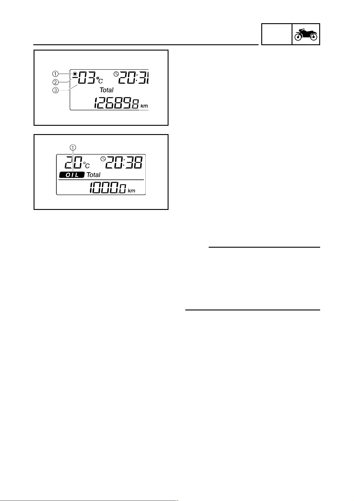
Ambient temperature display
This display shows the ambient temperature
from -30 °C to 50 °C.
The frost warning indicator “*” automatically
comes on if the temperature is lower than 3 °C.
Frost warning indicator
1
Negative symbol
2
Ambient temperature
3
Oil change indicator “OIL”
The engine oil should be changed when this
indicator comes on. The indicator stays on
until it is reset. After changing the engine oil,
reset the indicator as follows.
Oil change indicator “OIL”
1
To reset the oil change indicator:
1. Set the main switch to “ON” while holding
the “MODE” and “SET” buttons pushed for
two to five seconds.
2. Release the buttons, and the oil change
indicator will go off.
GEN
INFO
NOTE:
• The oil change indicator will come on at the
initial 1000 km and every 3000 km thereafter.
• If the engine oil is changed before the oil
change indicator comes on, the indicator
must be reset after the oil change for the
next periodic oil change to be indicated at
correct time.
1 - 4
IMPORTANT INFORMATION
EAS00020
IMPORTANT INFORMATION
PREPARATION FOR REMOVAL AND
DISASSEMBLY
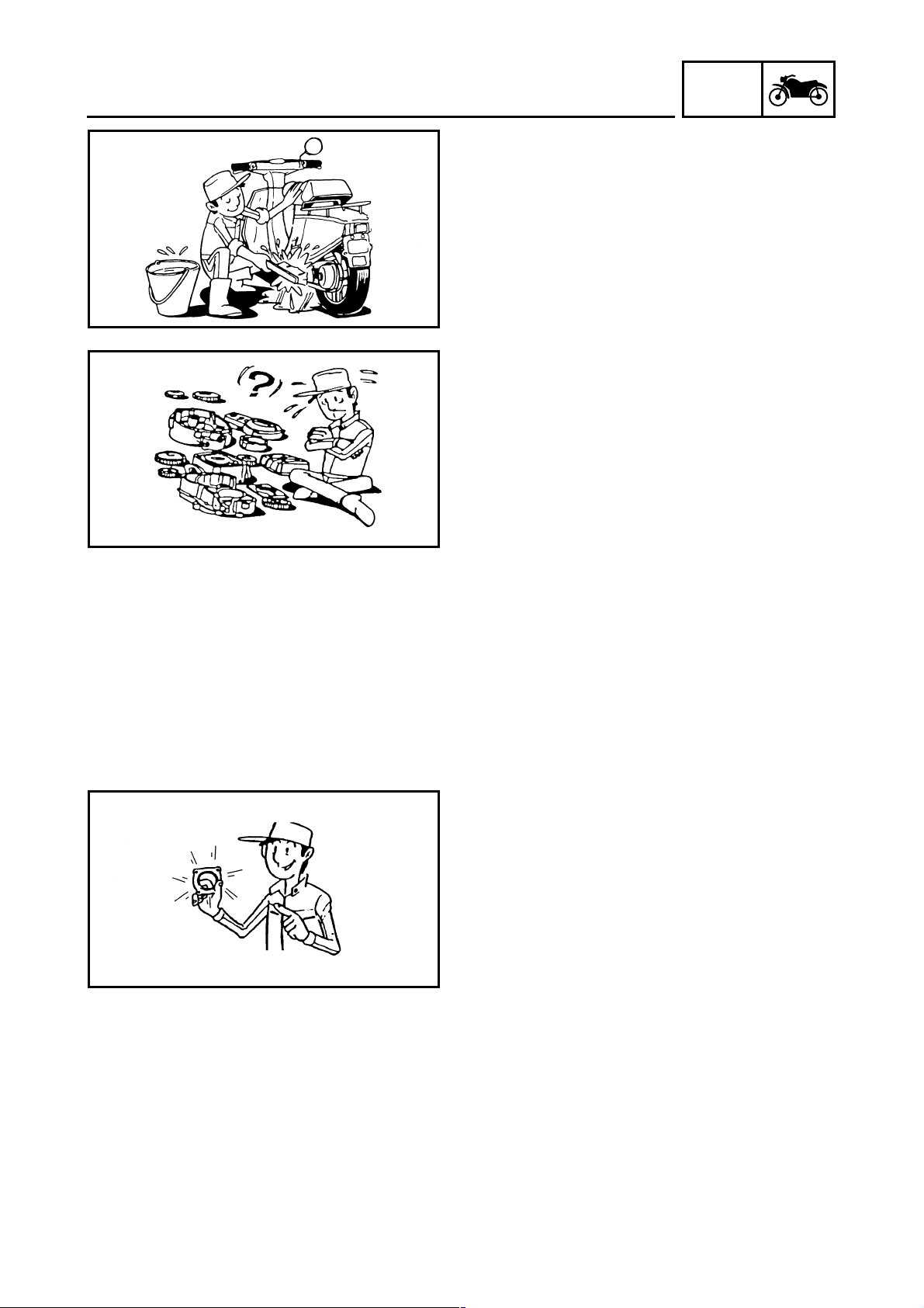
1. Before removal and disassembly, remove all
dirt, mud, dust and foreign material.
2. Use only the proper tools and cleaning
equipment.
Refer to “SPECIAL TOOLS”.
3. When disassembling, always keep mated
parts together. This includes gears, cylinders, pistons and other parts that have been
“mated” through normal wear. Mated parts
must always be reused or replaced as an
assembly.
4. During disassembly, clean all of the parts
and place them in trays in the order of disassembly. This will speed up assembly and
allow for the correct installation of all parts.
5. Keep all parts away from any source of fire.
GEN
INFO
EAS00021
REPLACEMENT PARTS
Use only genuine Yamaha parts for all
replacements. Use oil and grease recommended by Yamaha for all lubrication jobs.
Other brands may be similar in function and
appearance, but inferior in quality.
EAS00022
GASKETS, OIL SEALS AND O-RINGS
1. When overhauling the engine, replace all
gaskets, seals and O-rings. All gasket surfaces, oil seal lips and O-rings must be
cleaned.
2. During reassembly, properly oil all mating
parts and bearings and lubricate the oil seal
lips with grease.
1 - 5
IMPORTANT INFORMATION
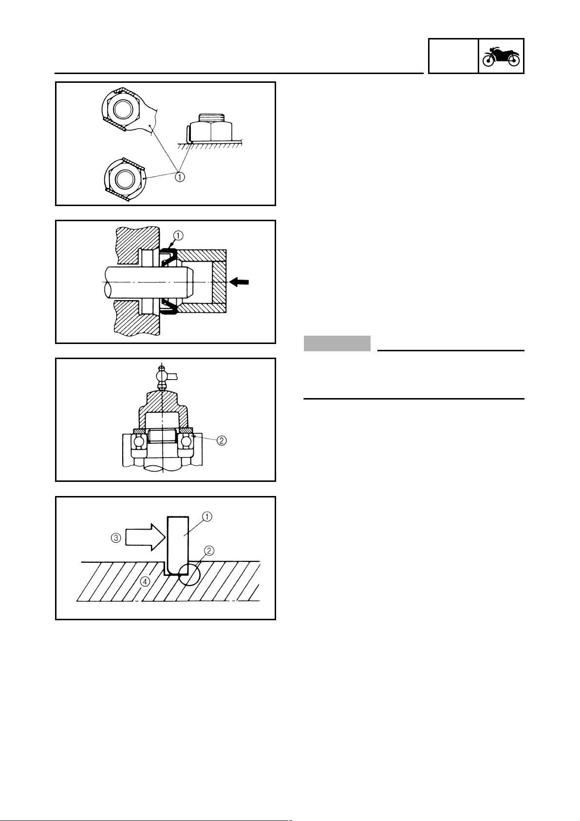
EAS00023
LOCK WASHERS/PLATES AND COTTER
PINS
After removal, replace all lock washers/plates
1
and cotter pins. After the bolt or nut has
been tightened to specification, bend the lock
tabs along a flat of the bolt or nut.
EAS00024
BEARINGS AND OIL SEALS
Install bearings and oil seals so that the manufacturer’s marks or numbers are visible. When
installing oil seals, lubricate the oil seal lips
with a light coat of lithium-soap-based grease.
Oil bearings liberally when installing, if appropriate.
Oil seal
1
GEN
INFO
CAUTION:
_
Do not spin the bearing with compressed
air because this will damage the bearing
surfaces.
Bearing
2
EAS00025
CIRCLIPS
Before reassembly, check all circlips carefully
and replace damaged or distorted circlips.
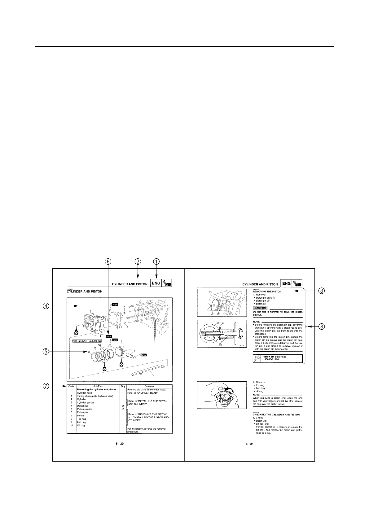
Always replace piston pin clips after one use.
When installing a circlip 1, make sure the
sharp-edged corner 2 is positioned opposite
the thrust 3 that the circlip receives.
Shaft
4
1 - 6
CHECKING THE CONNECTIONS
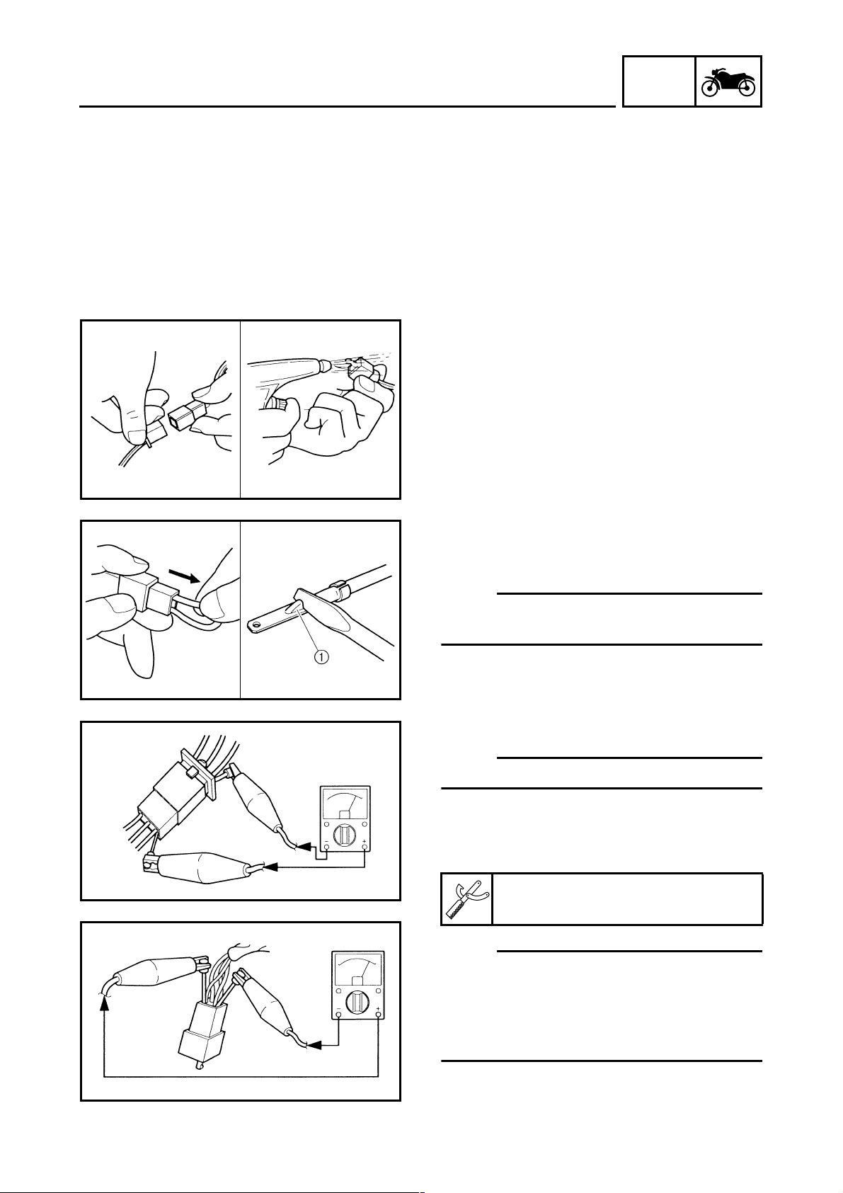
EAS00026
CHECKING THE CONNECTIONS
Check the leads, couplers, and connectors for
stains, rust, moisture, etc.
1. Disconnect:
• lead
• coupler
• connector
2. Check:
• lead
• coupler
• connector
Moisture → Dry with an air blower.
Rust/stains → Connect and disconnect several times.
GEN
INFO
3. Check:
• all connections
Loose connection → Connect properly.
NOTE:
_
If the pin 1 on the terminal is flattened, bend it
up.
4. Connect:
• lead
• coupler
• connector
NOTE:
_
Make sure all connections are tight.
5. Check:
• continuity
(with the pocket tester)
Pocket tester
90890-03112
NOTE:
_
• If there is no continuity, clean the terminals.
• When checking the wire harness, perform
steps (1) to (3).
• As a quick remedy, use a contact revitalizer
available at most part stores.
1 - 7
GEN
SPECIAL TOOLS
EAS00027
SPECIAL TOOLS
The following special tools are necessary for complete and accurate tune-up and assembly. Use
only the appropriate special tools as this will help prevent damage caused by the use of inappropriate tools or improvised techniques. Special tools, part numbers or both may differ depending on the
country.
When placing an order, refer to the list provided below to avoid any mistakes.
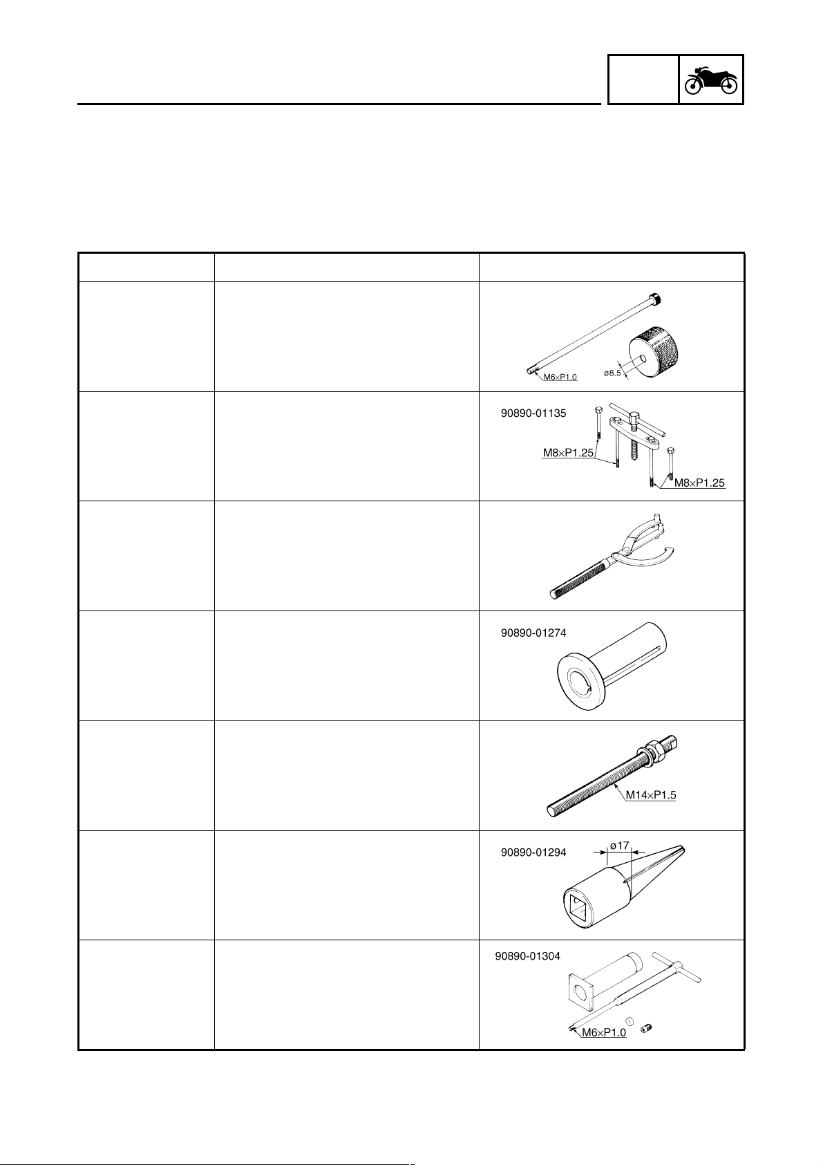
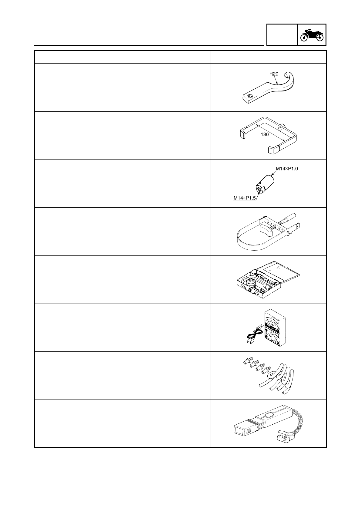
Tool No. Tool name/Function Illustration
Slide hammer bolt
Weight
90890-01083
90890-01084
These tools are used to remove or install
the rocker arm shafts.
Crankshaft separating tool
90890-01135
This tool is used to remove the crankshaft.
INFO
90890-01235
90890-01274
90890-01275
90890-01294
Rotor holding tool
This tool is used to hold the primary fixed
sheave.
Crankshaft installer pot
This tool is used to install the crankshaft.
Crankshaft installer bolt
This tool is used to install the crankshaft.
Damper rod holder
This tool is used to hold the damper rod
when removing or installing the damper
rod.
90890-01304
Piston pin puller set
This tool is used to remove the piston
pins.
1 - 8
GEN
SPECIAL TOOLS
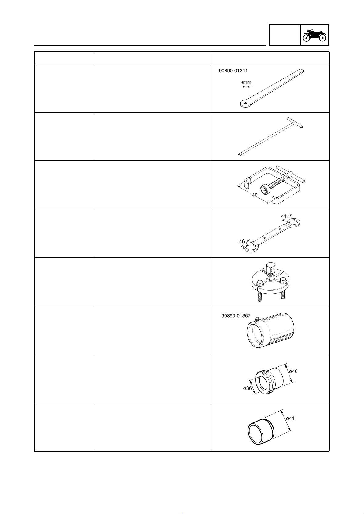
Tool No. Tool name/Function Illustration
Tappet adjusting tool
90890-01311
This tool is used to adjust valve clearance.
T-handle
INFO
90890-01326
90890-01337
90890-01348
90890-01362
This tool is used to hold the damper rod
when removing or installing the damper
rod.
Clutch spring holder
This tool is used to disassembly and
assembly the secondary sheave.
Locknut wrench
This tool is used to remove or install the
clutch carrier nut.
Flywheel puller
This tool is used to remove the generator
rotor.
Fork seal driver weight
90890-01367
90890-01370
90890-01396
This tool is used to install the oil seal,
dust seal, and the outer tube bushing of a
front fork leg.
Fork seal driver attachment (ø36)
This tool is used to install the oil seal and
the outer tube bushing of the front fork
leg.
Oil seal guide (ø41)
This tool is used for protecting the oil seal
lip when installing the secondary sliding
sheave.
1 - 9
GEN
SPECIAL TOOLS
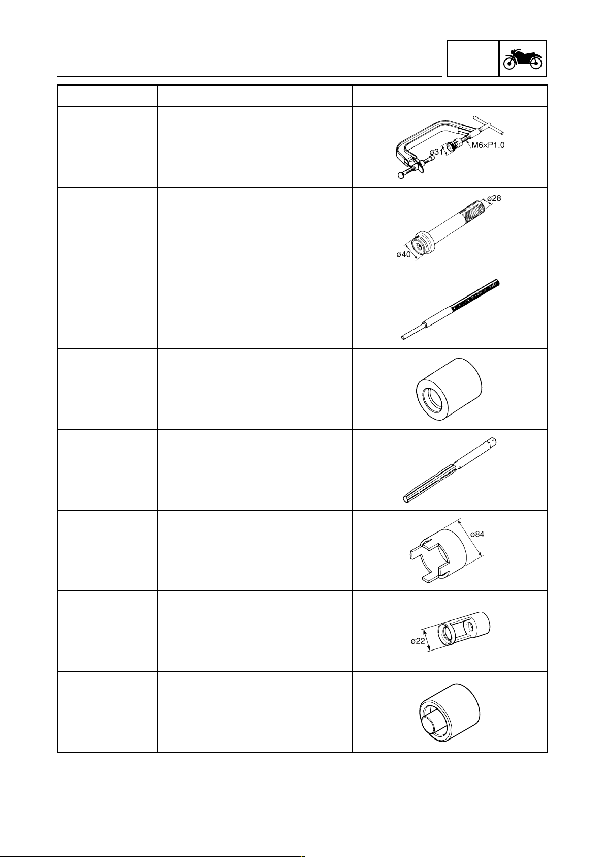
Tool No. Tool name/Function Illustration
Steering nut wrench
90890-01403
This tool is used to loosen or tighten the
steering ring nuts.
Clutch spring holder arm
90890-01464
This tool is used to disassembly and
assembly the secondary sheave.
Adapter (M14)
90890-01478
This tool is used to install the crankshaft.
INFO
90890-01701
90890-03081
90890-03112
90890-03134
Sheave holder
This tool is used to hold the generator
rotor, clutch housing, and clutch carrier.
Compression gauge
This tool is used to measure the engine
compression.
Pocket tester
This tool is used to check the electrical
system.
Exhaust attachment
This tool is used to measure the CO density.
90890-03141
Timing light
This tool is used to check the ignition timing.
1 - 10
GEN
SPECIAL TOOLS
Tool No. Tool name/Function Illustration
Valve spring compressor
90890-04019
This tool is used to remove or install the
valve assemblies.
Middle driven shaft bearing driver
90890-04058
This tool is used to install the water pump
seal.
Valve guide remover (ø6)
90890-04064
This tool is used to remove or install the
valve guides.
INFO
90890-04065
90890-04066
90890-04081
90890-04108
Valve guide installer (ø6)
This tool is used to install the valve
guides.
Valve guide reamer (ø6)
This tool is used to rebore the new valve
guides.
Spacer (crankshaft installer)
This tool is used to install the crankshaft.
Valve spring compressor attachment
This tool is used to remove or install the
valve assemblies.
90890-04132
Mechanical seal installer
This tool is used to install the water pump
seal.
1 - 11
GEN
SPECIAL TOOLS
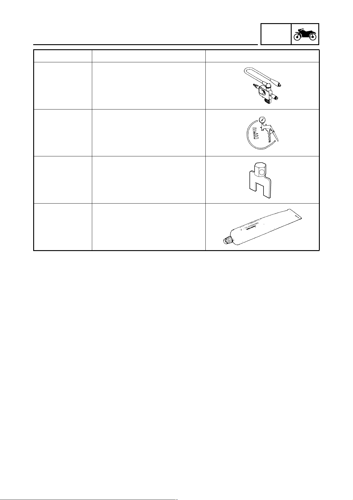
Tool No. Tool name/Function Illustration
Ignition checker
90890-06754
This tool is used to check the ignition system components.
Vacuum/pressure pump gauge set
90890-06756
This tool is used to check the air cut-off
valve.
Fuel sender removal tool
90890-11098
This tool are used to remove the fuel
sender.
INFO
90890-85505
Yamaha bond No. 1215
This bond is used to seal two mating surfaces (e.g., crankcase mating surfaces).
1 - 12

CHAPTER 2
SPECIFICATIONS
SPEC
GENERAL SPECIFICATIONS
ENGINE SPECIFICATIONS
CHASSIS SPECIFICATIONS
ELECTRICAL SPECIFICATIONS
CONVERSION TABLE
GENERAL TIGHTENING TORQUE SPECIFICATIONS
TIGHTENING TORQUES
ENGINE TIGHTENING TORQUES.........................................................2-19
CHASSIS TIGHTENING TORQUES.......................................................2-21
LUBRICATION POINTS AND LUBRICANT TYPES
ENGINE LUBRICATION POINTS AND LUBRICANT TYPES ................2-23
CHASSIS LUBRICATION POINTS AND LUBRICANT TYPES ..............2-24
..................................................................................2-18
........................................................................2-1
............................................................................2-2
........................................................................2-11
.................................................................2-15
...............................2-18
..............................................................................2-19
....................................2-23
COOLING SYSTEM DIAGRAMS
CABLE ROUTING
.........................................................................................2-26
..................................................................2-25
GENERAL SPECIFICATIONS
SPECIFICATIONS
GENERAL SPECIFICATIONS
Item Standard
SPEC
Model code
Dimensions
Overall length 2,210 mm (87.0 in)
Overall width 790 mm (31.1 in)
Overall height 1,380 mm (54.3 in)
Seat height 775 mm (30.5 in)
Wheelbase 1,545 mm (60.8 in)
Minimum ground clearance 113 mm (4.45 in)
Minimum turning radius 3,600 mm (143.7 in)
Weight
Wet (with oil and a full fuel tank) 176 kg (388 lb)
Maximum load (total of cargo, rider, passen-
ger, and accessories)
1C01
180 kg (397 lb)
2 - 1
ENGINE SPECIFICATIONS
SPEC
ENGINE SPECIFICATIONS
Item Standard Limit
Engine
Engine type Liquid cooled 4-stroke, SOHC ---Displacement 249.7 cm
Cylinder arrangement Forward-inclined single cylinder ---Bore × stroke 69.0 × 66.8 mm (2.72 × 2.63 in) ---Compression ratio 10.00 :1 ---Standard compression pressure (at
sea level)
Starting system Electric starter ----
Fuel
Recommended fuel Regular unleaded gasoline only ---Fuel tank capacity
Total (including reserve) 13.0 L (2.86 Imp.gal, 3.43 US gal) ---Fuel reserve amount 2.0 L (0.44 Imp.gal, 0.53 US gal) ----
Engine oil
Lubrication system Wet sump ---Recommended oil type SAE10W30, SAE10W40, SAE15W40,
Recommended engine oil grade API service SG type or higher, JASO
Quantity
Total amount 1.40 L (1.23 Imp.qt, 1.48 US qt) ---Periodic oil change 1.20 L (1.06 Imp.qt, 1.27 US qt) ---Oil temperature 65 ~ 75 °C (149 ~ 167 °F) ----
Final transmission oil
Type SAE10W30 type SE motor oil ---Oil quantity 0.25 L (0.22 Imp.qt, 0.26 US qt) ----
1,400 kPa (14.0 kgf/cm
500 r/min
SAE20W40, or SAE20W50
standard MA
3
2
, 199.1 psi) at
----
----
----
----
2 - 2
ENGINE SPECIFICATIONS
Item Standard Limit
Oil pump
Oil pump type Trochoid ---Inner-rotor-to-outer-rotor-tip clearance
Outer-rotor-to-oil-pump-housing
clearance
Oil-pump-housing-to-inner-and-
outer-rotor clearance
Cooling system
Radiator and engine capacity 0.70 L (0.62 Imp.qt, 0.74 US qt) ---Radiator capacity 0.34 L (0.30 Imp.qt, 0.36 US qt) ---Radiator core
Width 229.0 mm (9.02 in) ---Height 111.5 mm (4.39 in) ----
Depth 33.0 mm (1.30 in) ---Coolant reservoir capacity (up to the
maximum level mark)
Water pump
Water pump type Single suction centrifugal pump ----
Reduction ratio 37/22 × 25/37 (1.136) ----
Impeller shaft tilt limit ---- 0.15 mm
Coolant temperature 80 ~ 90 °C (176 ~ 194 °F) ----
Spark plug
Manufacturer/model × quantity NGK/DR8EA × 1 ---Spark plug gap 0.6 ~ 0.7 mm (0.024 ~ 0.028 in) ----
Cylinder head
Maximum warpage ---- 0.05 mm
Less than 0.15 mm (0.0059 in) 0.23 mm
0.013 ~ 0.036 mm (0.0005 ~ 0.0014 in) 0.106 mm
0.04 ~ 0.09 mm (0.0016 ~ 0.0035 in) 0.16 mm
0.26 L (0.23 Imp.qt, 0.28 US qt) ----
SPEC
(0.0091 in)
(0.0042 in)
(0.0063 in)
(0.0059 in)
(0.0020 in)
2 - 3
ENGINE SPECIFICATIONS
Item Standard Limit
Camshaft
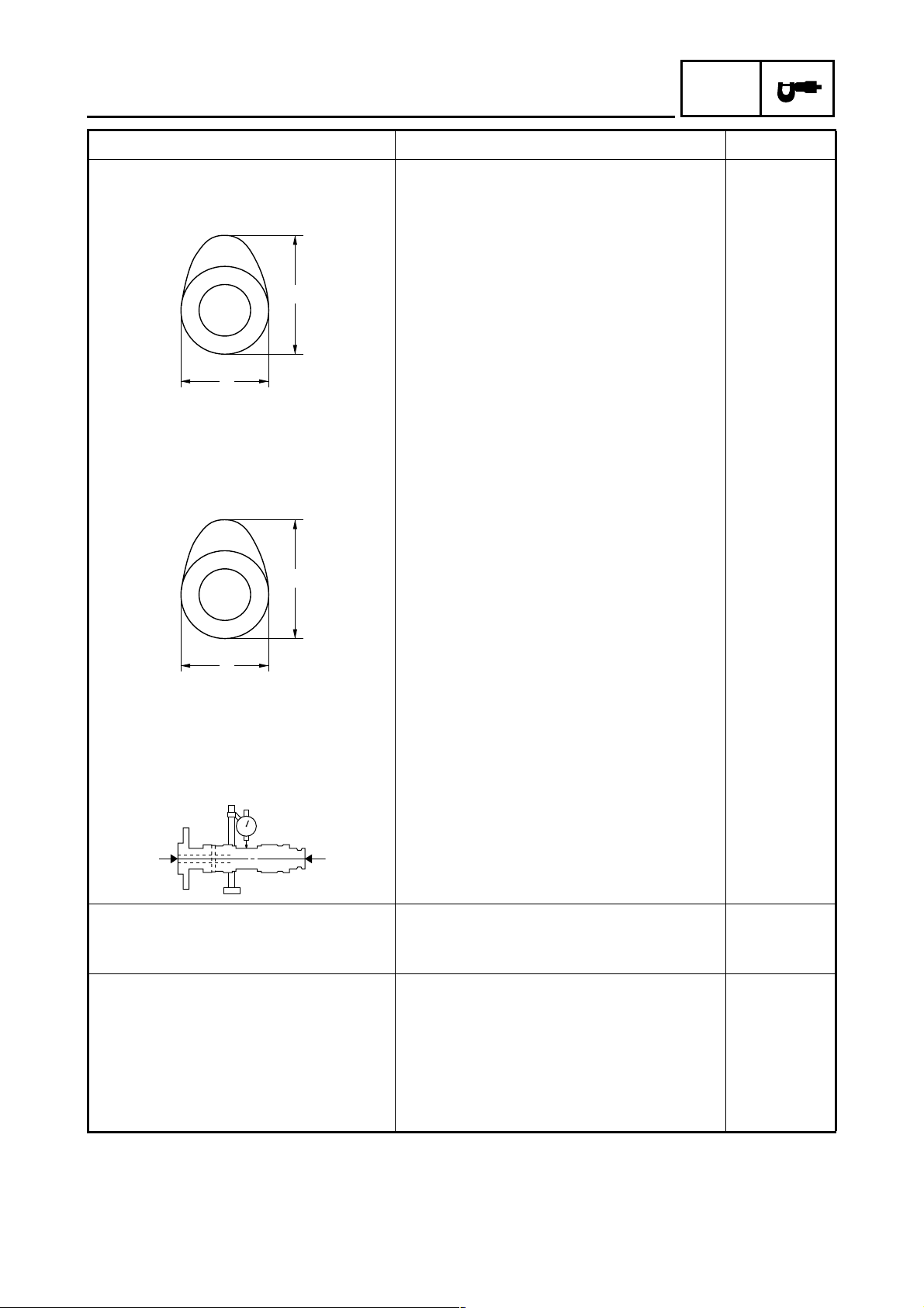
Drive system Chain drive (left) ---Intake camshaft lobe dimensions
A
B
Measurement A 37.051 ~ 37.151 mm (1.4587 ~ 1.4626 in) 36.956 mm
Measurement B 30.074 ~ 30.174 mm (1.1840 ~ 1.1880 in) 29.973 mm
Exhaust camshaft lobe dimensions
SPEC
(1.4550 in)
(1.1800 in)
A
B
Measurement A 37.053 ~ 37.153 mm (1.4588 ~ 1.4627 in) 36.956 mm
(1.4550 in)
Measurement B 30.091 ~ 30.191 mm (1.1847 ~ 1.1886 in) 29.194 mm
(1.1494 in)
Maximum camshaft runout ---- 0.030 mm
(0.0012 in)
Timing chain
Model/number of links DID SC.A-0404A SV/104 ---Tensioning system Automatic ----
Rocker arms/rocker arm shafts
Rocker arm inside diameter 12.000 ~ 12.018 mm (0.4724 ~ 0.4731 in) 12.030 mm
(0.4736 in)
Rocker arm shaft outside diameter 11.981 ~ 11.991 mm (0.4717 ~ 0.4721 in) 11.950 mm
(0.4705 in)
Rocker-arm-to-rocker-arm-shaft
clearance
0.009 ~ 0.037 mm (0.0004 ~ 0.0015 in) 0.080 mm
(0.0031 in)
2 - 4
ENGINE SPECIFICATIONS
Item Standard Limit
Valves, valve seats, valve guides
Valve clearance (cold)
Intake 0.08 ~ 0.12 mm (0.0031 ~ 0.0047 in) ---Exhaust 0.16 ~ 0.20 mm (0.0063 ~ 0.0079 in) ----
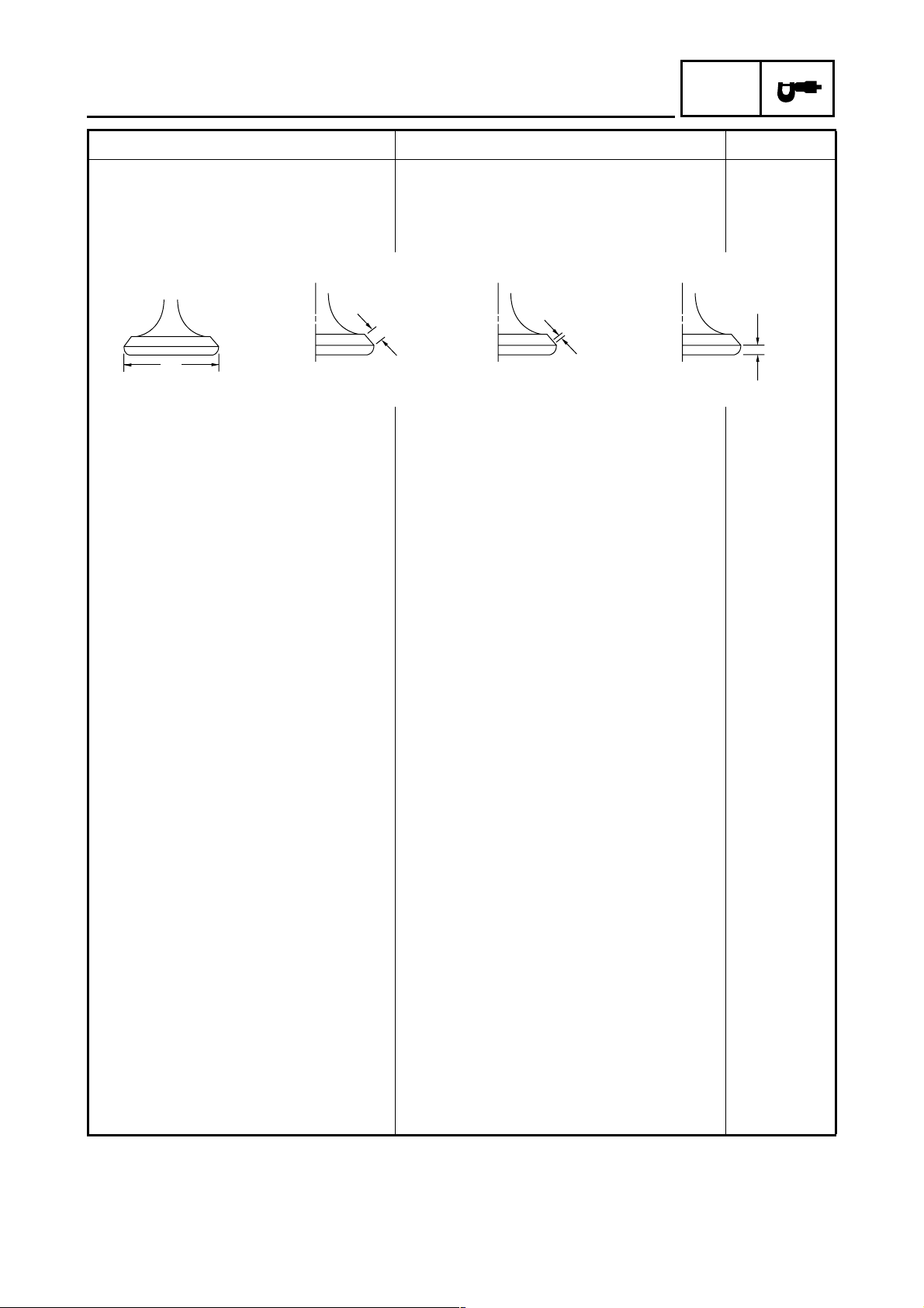
Valve dimensions
SPEC
B
A
Head Diameter Face Width Seat Width Margin Thickness
Valve head diameter A
Intake 33.90 ~ 34.10 mm (1.3346 ~ 1.3425 in) ---Exhaust 28.40 ~ 28.60 mm (1.1181 ~ 1.1260 in) ----
Valve face width B
Intake 3.394 ~ 3.960 mm (0.1336 ~ 0.1559 in) ---Exhaust 3.394 ~ 3.960 mm (0.1336 ~ 0.1559 in) ----
Valve seat width C
Intake 0.90 ~ 1.10 mm (0.0354 ~ 0.0433 in) 1.6 mm
Exhaust 0.90 ~ 1.10 mm (0.0354 ~ 0.0433 in) 1.6 mm
Valve margin thickness D
Intake 0.80 ~ 1.20 mm (0.0315 ~ 0.0472 in) 0.5 mm
Exhaust 0.80 ~ 1.20 mm (0.0315 ~ 0.0472 in) 0.5 mm
Valve stem diameter
Intake 5.975 ~ 5.990 mm (0.2352 ~ 0.2358 in) 5.940 mm
Exhaust 5.960 ~ 5.975 mm (0.2346 ~ 0.2352 in) 5.920 mm
Valve guide inside diameter
Intake 6.000 ~ 6.012 mm (0.2362 ~ 0.2367 in) 6.050 mm
Exhaust 6.000 ~ 6.012 mm (0.2362 ~ 0.2367 in) 6.050 mm
Valve-stem-to-valve-guide clearance
Intake 0.010 ~ 0.037 mm (0.0004 ~ 0.0015 in) 0.080 mm
Exhaust 0.025 ~ 0.052 mm (0.0010 ~ 0.0020 in) 0.100 mm
C
D
(0.06 in)
(0.06 in)
(0.02 in)
(0.02 in)
(0.2339 in)
(0.2331 in)
(0.2382 in)
(0.2382 in)
(0.0031 in)
(0.0039 in)
2 - 5
ENGINE SPECIFICATIONS
Item Standard Limit
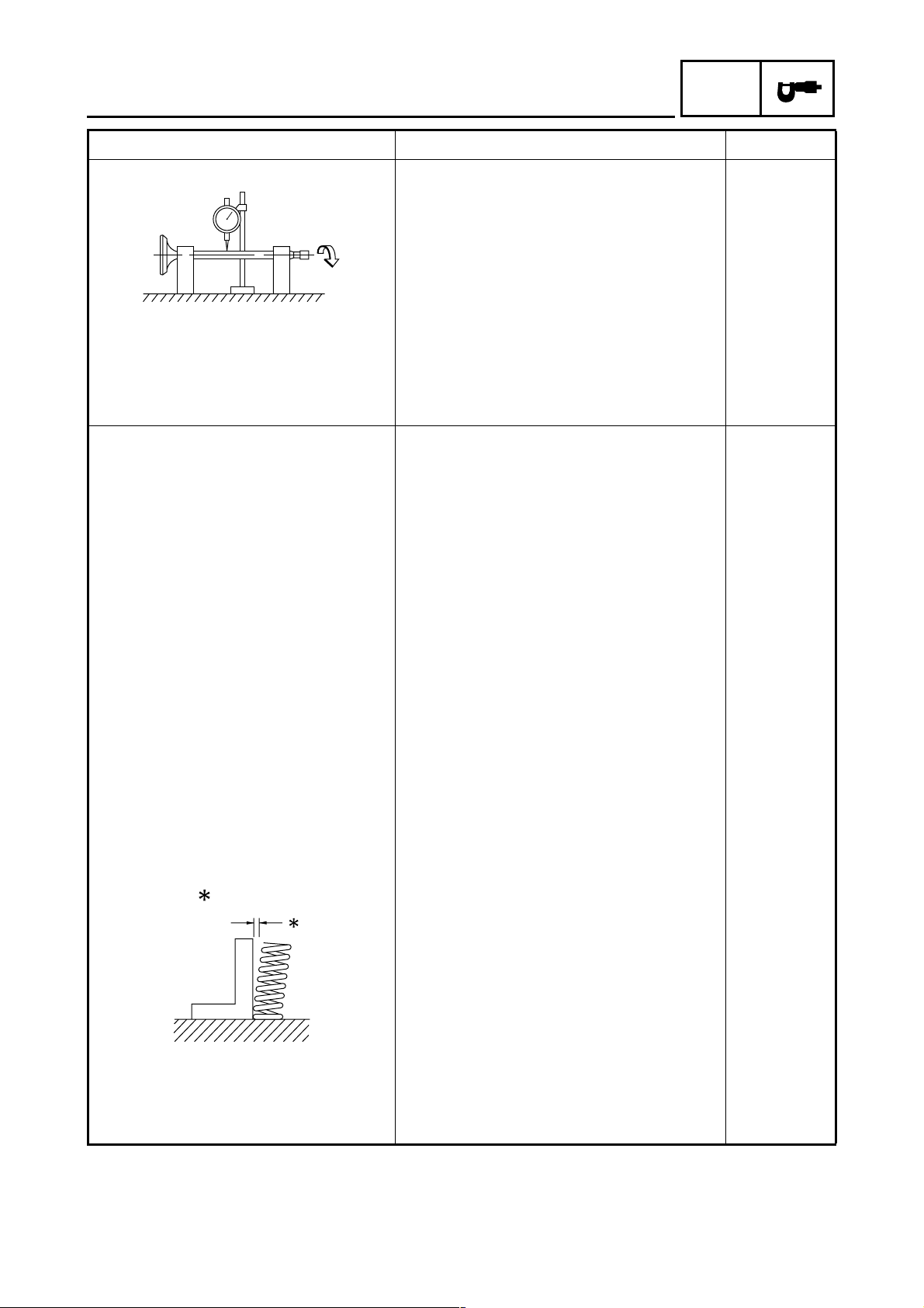
Valve stem runout ---- 0.010 mm
Cylinder head valve seat width
Intake 0.90 ~ 1.10 mm (0.0354 ~ 0.0433 in) 1.6 mm
Exhaust 0.90 ~ 1.10 mm (0.0354 ~ 0.0433 in) 1.6 mm
Valve springs
Inner spring
Free length
Intake 38.10 mm (1.50 in) 36.10 mm
Exhaust 38.10 mm (1.50 in) 36.10 mm
Installed length (valve closed)
Intake 30.10 mm (1.19 in) ----
Exhaust 30.10 mm (1.19 in) ---Spring rate - intake (K1) 10.29 N/mm (1.05 kgf/mm, 58.75 lb/in) ---Spring rate - intake (K2) 13.37 N/mm (1.36 kgf/mm, 76.34 lb/in) ---Spring rate - exhaust (K1) 10.29 N/mm (1.05 kgf/mm, 58.75 lb/in) ---Spring rate - exhaust (K2) 13.37 N/mm (1.36 kgf/mm, 76.34 lb/in) ---Compression spring force
(installed)
Intake 76 ~ 88 N
(7.80 ~ 9.00 kgf, 17.20 ~ 19.85 lbf)
Exhaust 76 ~ 88 N
(7.80 ~ 9.00 kgf, 17.20 ~ 19.85 lbf)
Spring tilt
SPEC
(0.0004 in)
(0.06 in)
(0.06 in)
(1.42 in)
(1.42 in)
----
----
Intake ---- 2.5°/1.7 mm
(2.5°/0.067 in)
Exhaust ---- 2.5°/1.7 mm
(2.5°/0.067 in)
2 - 6
ENGINE SPECIFICATIONS
Item Standard Limit
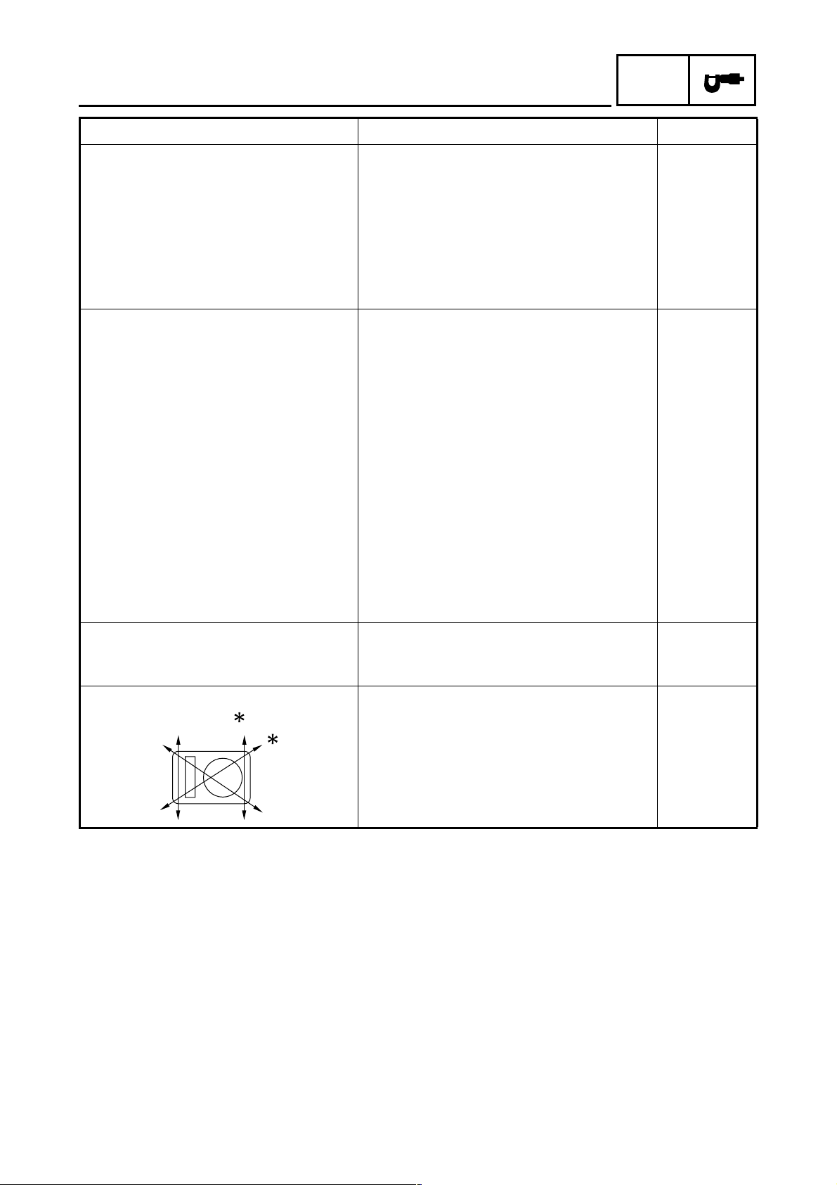
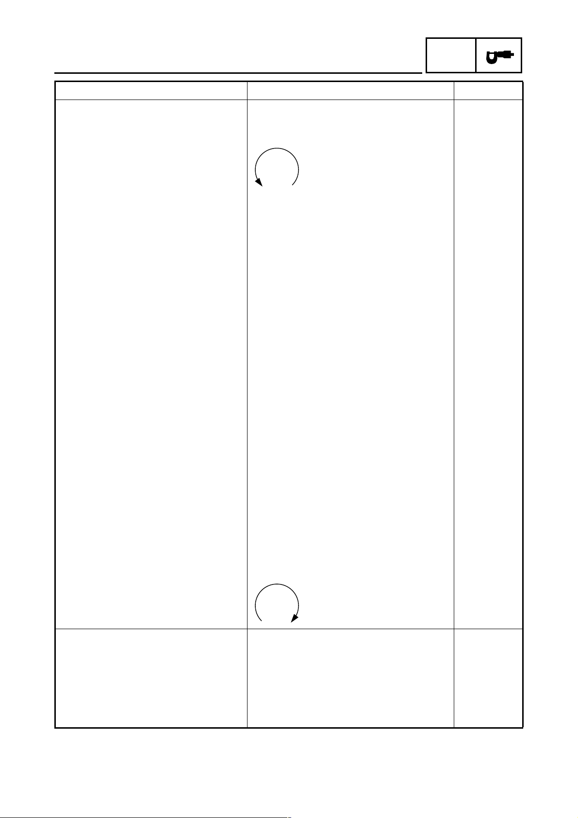
Winding direction (top view)
Intake Counterclockwise ----
Exhaust Counterclockwise ----
Outer spring
Free length
Intake 36.93 mm (1.45 in) 35.00 mm
Exhaust 36.93 mm (1.45 in) 35.00 mm
Installed length (valve closed)
Intake 31.60 mm (1.24 in) ----
Exhaust 31.60 mm (1.24 in) ---Spring rate - intake (K1) 23.18 N/mm (2.36 kgf/mm, 132.36 lb/in) ---Spring rate - intake (K2) 31.66 N/mm (3.23 kgf/mm, 180.78 lb/in) ---Spring rate - exhaust (K1) 23.18 N/mm (2.36 kgf/mm, 132.36 lb/in) ---Spring rate - exhaust (K2) 31.66 N/mm (3.23 kgf/mm, 180.78 lb/in) ---Compression spring force
(installed)
Intake 115 ~ 133 N (11.73 ~ 13.56 kgf,
25.85 ~ 29.90 lbf)
Exhaust 115 ~ 133 N (11.73 ~ 13.56 kgf,
25.85 ~ 29.90 lbf)
Spring tilt
Intake ---- 2.5°/1.6 mm
Exhaust ---- 2.5°/1.6 mm
Winding direction
Intake Clockwise ----
Exhaust Clockwise ----
SPEC
(1.38 in)
(1.38 in)
(2.5°/0.063 in)
(2.5°/0.063 in)
----
----
Cylinder
Bore 69.000 ~ 69.005 mm (2.7165 ~ 2.7167 in) 69.100 mm
(2.7205 in)
Maximum taper ---- 0.050 mm
(0.0020 in)
Maximum out of round ---- 0.030 mm
(0.0012 in)
2 - 7
ENGINE SPECIFICATIONS
Item Standard Limit
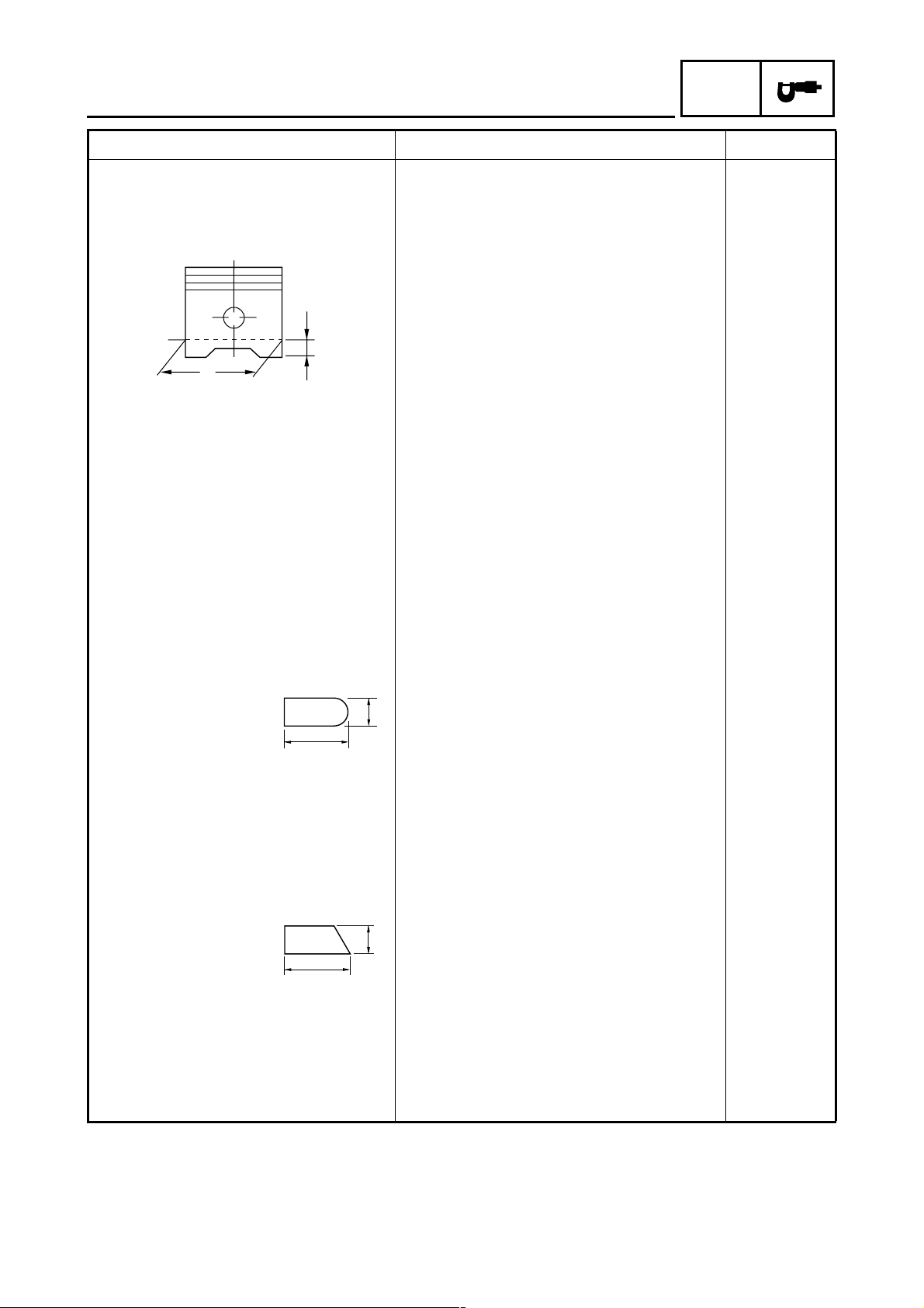
Piston
Piston-to-cylinder clearance 0.020 ~ 0.040 mm (0.0008 ~ 0.0016 in) 0.15 mm
Diameter D 68.965 ~ 68.980 mm (2.7152 ~ 2.7157 in) ----
H
D
Height H 5.0 mm (0.20 in) ---Piston pin bore (in the piston)
Diameter 17.004 ~ 17.015 mm (0.6694 ~ 0.6699 in) 17.045 mm
Offset 0.50 mm (0.0197 in) ---Offset direction Intake side ----
Piston pin
Outside diameter 16.991 ~ 17.000 mm (0.6689 ~ 0.6693 in) 16.971 mm
Piston-pin-to-piston-pin-bore clearance
Piston rings
Top ring
0.004 ~ 0.024 mm (0.0002 ~ 0.0009 in) 0.074 mm
SPEC
(0.0059 in)
(0.6711 in)
(0.6681 in)
(0.0029 in)
B
T
Ring type Barrel ----
Dimensions (B × T) 1.00 × 2.60 mm (0.04 × 0.10 in) ----
End gap (installed) 0.15 ~ 0.30 mm (0.0059 ~ 0.0118 in) 0.45 mm
(0.0177 in)
Ring side clearance 0.040 ~ 0.080 mm (0.0016 ~ 0.0031 in) 0.120 mm
(0.0047 in)
2nd ring
B
T
Ring type Taper ----
Dimensions (B × T) 1.00 × 2.90 mm (0.04 × 0.11 in) ----
End gap (installed) 0.30 ~ 0.45 mm (0.0118 ~ 0.0177 in) 0.70 mm
(0.0276 in)
Ring side clearance 0.030 ~ 0.070 mm (0.0012 ~ 0.0028 in) 0.120 mm
(0.0047 in)
2 - 8
ENGINE SPECIFICATIONS
Item Standard Limit
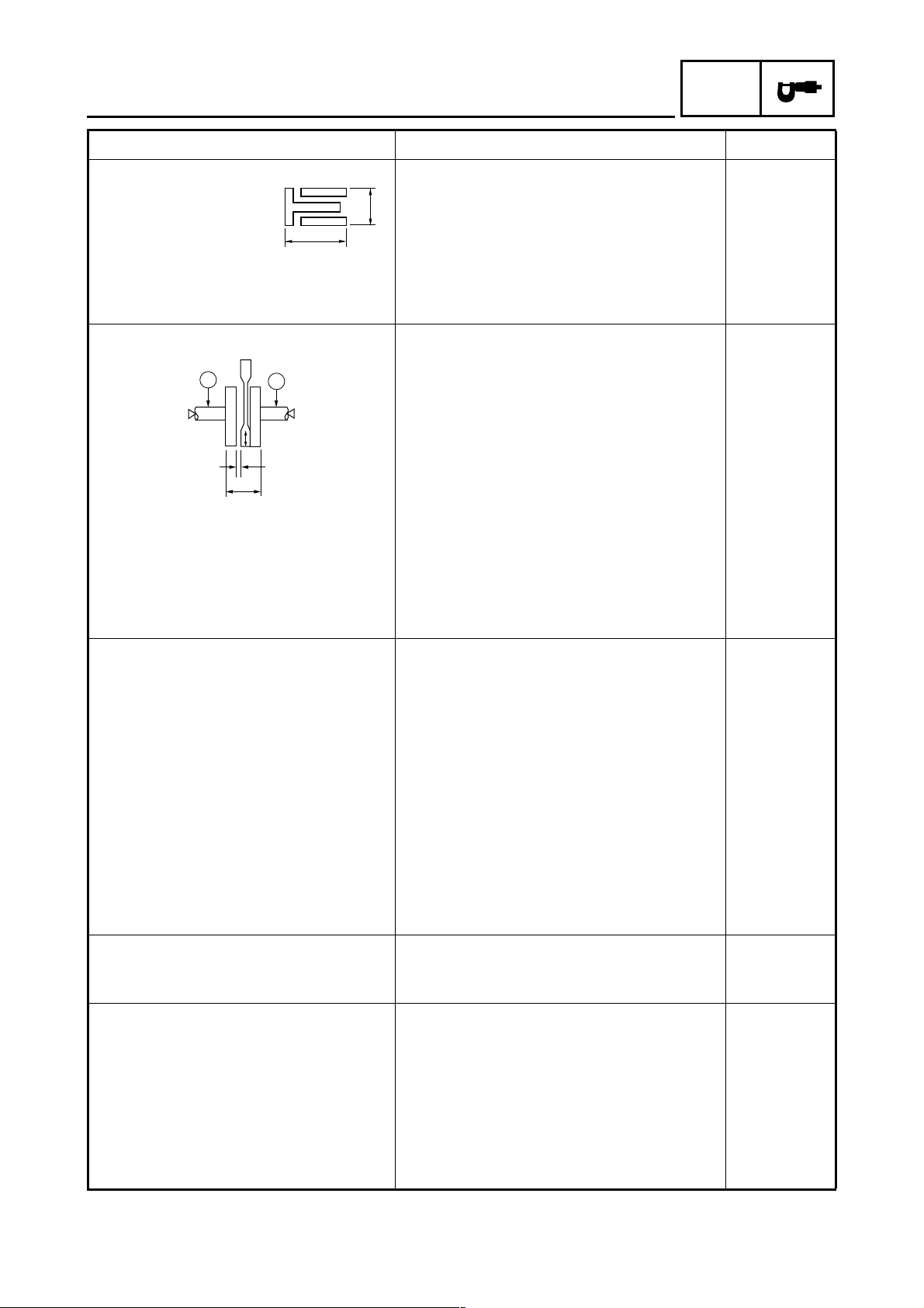
Oil ring
B
T
Dimensions (B × T) 1.50 × 2.50 mm (0.06 × 0.10 in) ----
End gap (installed) 0.20 ~ 0.70 mm (0.0079 ~ 0.0276 in) ----
Ring side clearance 0.060 ~ 0.150 mm (0.0024 ~ 0.0059 in) ----
Crankshaft
SPEC
C
Width A 59.75 ~ 59.80 mm (2.352 ~ 2.354 in) ---Maximum runout C ---- 0.030 mm
Big end side clearance D 0.350 ~ 0.850 mm (0.0138 ~ 0.0335 in) ---Big end radial clearance E 0.010 ~ 0.025 mm (0.0004 ~ 0.0010 in) ----
Automatic centrifugal clutch
Clutch type Dry, centrifugal automatic ---Clutch shoe thickness 3.3 mm (0.13 in) 2.0 mm
Clutch shoe spring free length 31.3 mm (1.23 in) ---Clutch housing inside diameter 145.0 mm (5.71 in) 145.5 mm
Compression spring free length 102.4 mm (4.03 in) 90.0 mm
Primary sheave weight outside diameter
Clutch-in revolution 2,250 ~ 2,850 r/min ---Clutch-stall revolution 3,700 ~ 4,700 r/min ----
V-belt
V-belt width 23.0 mm (0.91 in) 21.0 mm
Transmission
Transmission type V-belt automatic ---Primary reduction system Helical gear ---Primary reduction ratio 40/15 (2.666) ---Secondary reduction system Helical gear ---Secondary reduction ratio 40/14 (2.857) ---Operation Centrifugal automatic type ---Single speed automatic 2.44 ~ 0.83 : 1 ----
C
E
D
A
(0.0012 in)
(0.08 in)
(5.73 in)
(3.54 in)
20.0 mm (0.79 in) 19.5 mm
(0.77 in)
(0.83 in)
2 - 9
ENGINE SPECIFICATIONS
Item Standard Limit
Air filter
Air filter element Oil-coated paper element ----
Fuel pump
Pump type Electrical ---Model/manufacturer 2GV0/MITSUBISHI ---Output pressure 12.5 kPa (0.13 kgf/cm
Carburetor
Type × quantity 1C0 × 1 ---Manufacturer KEIHIN ---ID mark 1C0D ---Main jet #122 ---Main air jet #90 ---Jet needle N425-DVD00 ---Needle jet 2.6 ---Pilot air jet 1 #125 ---Pilot outlet 0.85 ---Pilot jet #35 ---Bypass 1 0.7 ---Bypass 2 0.7 ---Bypass 3 0.7 ---Bypass 4 0.7 ---Pilot screw turns out 2 ---Valve seat size 1.6 ---Starter jet 1 #38 ---Throttle valve size 10 ---Float height 17.5 mm (0.69 in) ----
Idling condition
Engine idling speed 1,550 ~ 1,650 r/min ---CO density (when air induction system is operating)
CO density (when air induction sys-
tem is not operating)
Throttle cable free play 4.0 ~ 6.0 mm (0.16 ~ 0.24 in) ----
4.0% ----
6.0% ----
2
, 1.8 psi) ----
SPEC
2 - 10
 Loading...