

Yamaha YP30G, YP20G Owner's Manual

OWNER’S MANUAL
Read this manual carefully before operating this machine.
YP20G
070009301
YP30G
9CB-F8199-70

Read this manual carefully before operating this machine. This manual
should stay with this machine if it is sold.

INTRODUCTION
Congratulations on your purchase of your new Yamaha.
This manual will provide you with a good basic understanding of the operation and
maintenance of this machine.
If you have any questions regarding the operation or maintenance of your machine,
please consult a Yamaha dealer.
YP20G/YP30G
OWNER’S MANUAL
© 2015 by Yamaha Motor Powered
Products Co., Ltd.
1st Edition, January 2015
All rights reserved.
Any reprinting or unauthorized use
without the written permission of
Yamaha Motor Powered
Products Co., Ltd.
is expressly prohibited.
Printed in China
IMPORTANT MANUAL
INFORMATION
Particularly important information is distinguished in this manual by the following
notations.
This is the safety alert symbol. It is
used to alert you to potential personal
injury hazards. Obey all safety messages that follow this symbol to avoid possible injury or death.
WARNING
A WARNING indicates a hazardous situation which, if not avoided, could
result in death or serious injury.
NOTICE
A NOTICE indicates special precautions that must be taken to avoid damage to the machine or other property.
TIP
A TIP provides key information to make
procedures easier or clearer.
WARNING
PL EASE READ AND UNDERSTAND
THIS MANUAL COMPLETELY BEFORE
OPERATING THE MACHINE.
TIP
9 Yamaha continually seeks advance-
ments in product design and quality.
Therefore, while this manual contains
the most current product information
available at the time of printing, there
may be minor discrepancies between
your machine and this manual. If
there is any question concerning this
manual, please consult a Yamaha
dealer.
9 This manual should be considered a
permanent part of this machine and
should remain wi t h this machine
when resold.
* Product and specifications are subject to
change without notice.

CONTENTS
SAFETY INFORMATION ...................... 1
Exhaust fumes are poisonous ............1
Fuel is highly flammable and
poisonous ...........................................1
Engine and muffler may be hot .......... 1
LOCATION OF IMPORTANT
LABELS ................................................ 3
DESCRIPTION ...................................... 4
CONTROL FUNCTION ......................... 5
Oil warning light (Red)........................ 5
Engine switch ..................................... 5
Throttle lever ...................................... 5
Fuel cock lever ................................... 6
Choke lever ........................................ 6
Recoil starter ...................................... 6
PREPARATION ..................................... 7
Fuel .................................................... 7
Engine oil ...........................................8
Water hose installation .......................9
Water priming ...................................10
PRE-OPERATION CHECK .................11
Pre-operation check ......................... 11
OPERATION ....................................... 12
Preparation for operation.................. 12
Water priming ...................................12
Starting the engine ........................... 13
Stopping the engine ......................... 14
Drain water after use ........................15
High altitude operation .................... 15
PERIODIC MAINTENANCE ................ 16
Maintenance chart ........................... 16
Spark plug inspection ....................... 17
Carburetor adjustment ..................... 18
Water leakage check ........................ 18
Engine oil replacement ..................... 18
Air filter ............................................. 20
Fuel cock .......................................... 21
Fuel tank filter ................................... 22
Muffler screen and spark arrester .... 22
Troubleshooting ................................ 24
STORAGE ...........................................27
Drain the fuel .................................... 27
Engine .............................................. 29
SPECIFICATIONS ............................... 30
Dimensions ...................................... 30
Engine .............................................. 30
Pump ................................................ 30
CONSUMER INFORMATION.............. 31
Identification number records ........... 31
Machine identification ....................... 31
EXHAUST EMISSION CONTROL
SYSTEM AND COMPONENTS .......... 32
WIRING DIAGRAM ............................. 33
RUBBER MOUNT INSTALLATION .... 34
745-013
745-014
745-016
SAFETY INFORMATION
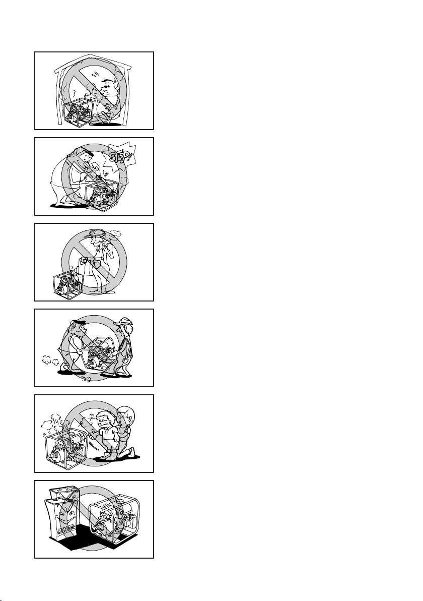
Exhaust fumes are poisonous
9 Using a water pump indoors CAN KILL YOU IN
MINUTES. Engine exhaust contains carbon monoxide. This is a poison you cannot see or smell.
9 NEVER use inside a home or garage, EVEN IF
doors and windows are open.
9 Only use OUTSIDE and far away from windows,
doors, and vents.
Fuel is highly flammable and poisonous
9 Always turn off the engine when refuelling.
9 Never refuel while smoking or in the vicinity of an
open flame.
9 Take care not to spill any fuel on the engine or
muffler when refuelling.
9 Do not leave the water pump inside the vehicle or
in the trunk.
9 If you swallow any fuel, inhale fuel vapor, or allow
any to get in your eye(s), see your doctor immediately. If any fuel spills on your skin or clothing,
immediately wash with soap and water and
change your clothes.
9 When operating or transporting the water pump,
be sure it is kept upright. If it tilts, fuel may leak
from the carburetor or fuel tank.
745-015
745-017
745-018
Engine and muffler may be hot
9 Place the water pump in a place where pedestri-
ans or children are not likely to touch the water
pump.
9 Do not place any flammable materials near the
exhaust outlet during operation.
– 1 –

745-019a
745-020
9 In order to prevent overheating, ensure adequate
airflow by keeping the machine at least 1 m (3 ft)
from objects or other equipment.
9 Do not operate the engine with a dust cover or
other objects covering it.
9 When covering the water pump, be sure to do so
only after the engine and muffler have completely
cooled down.
– 2 –
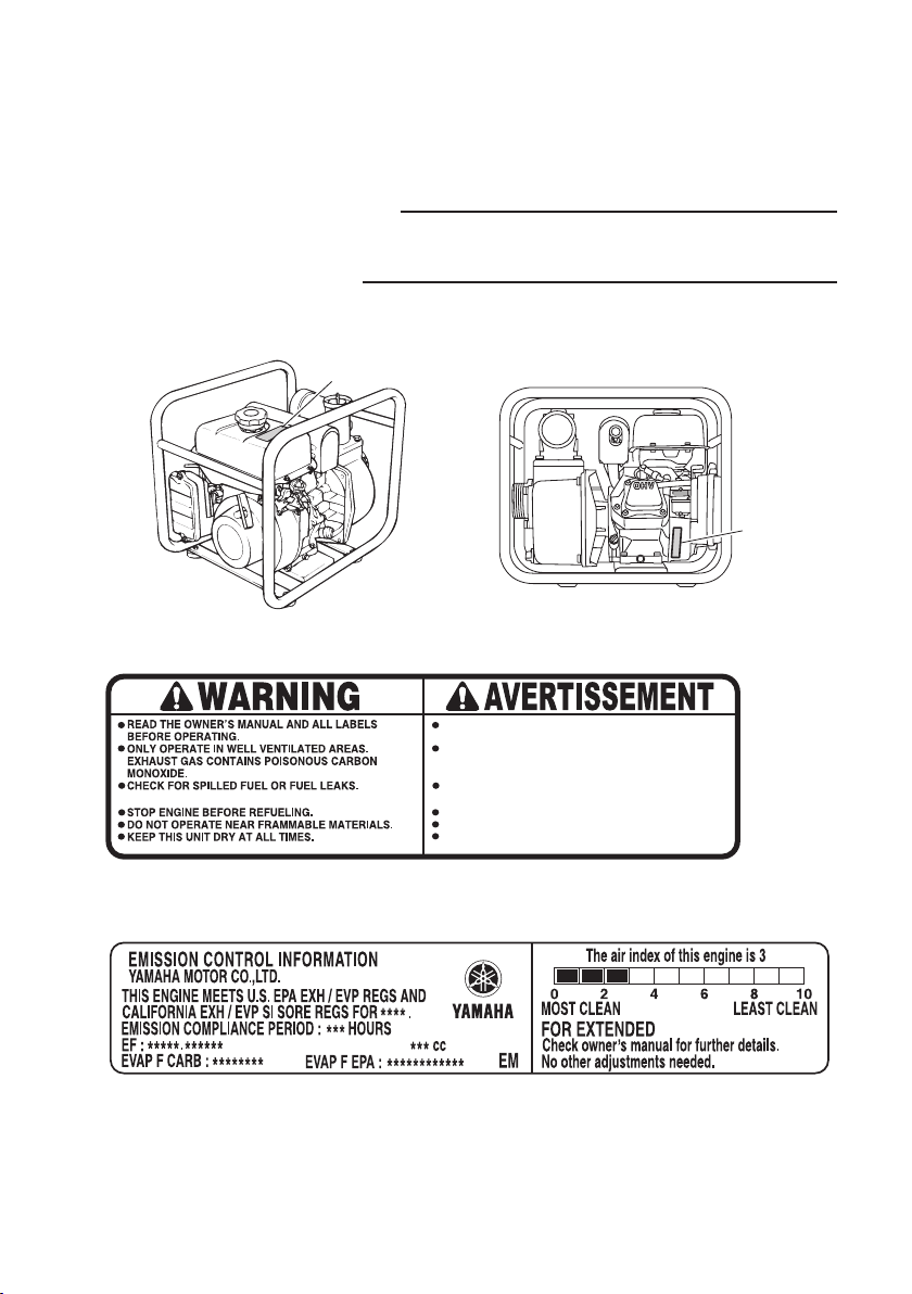
LOCATION OF IMPORTANT LABELS
Please read the following labels carefully before operating this water pump.
TIP
Maintain or replace safety and instruction labels, as
necessary.
1
2
792-016
1
LISEZ LE MANUEL DU PROPRIÉTAIRE ET TOUTES LES
ÉTIQUETTES AVANT L'UTILISATION.
NE FAITES FONCTIONNER QUE DANS DES LIEUX BIEN AÉRÉS.
LES GAZ D'ÉCHAPPEMENT CONTIENNENT DU MONOXYDE DE
CARBONE NOCIF.
VÉRIFIEZ QU'IL N'Y A PAS DE FUITES DE CARBURANT OU DE
CARBURANT RENVERSÉ.
ARRÊTEZ LE MOTEUR AVANT DE FAIRE LE PLEIN.
NE PAS UTILISER PRÈS DE MATÉRIAUX INFLAMMABLES.
GARDEZ L'APPAREIL AU SEC EN TOUTES CIRCONSTANCES.
7CN-F4162-60
2
DISPLACEMENT :
– 3 –
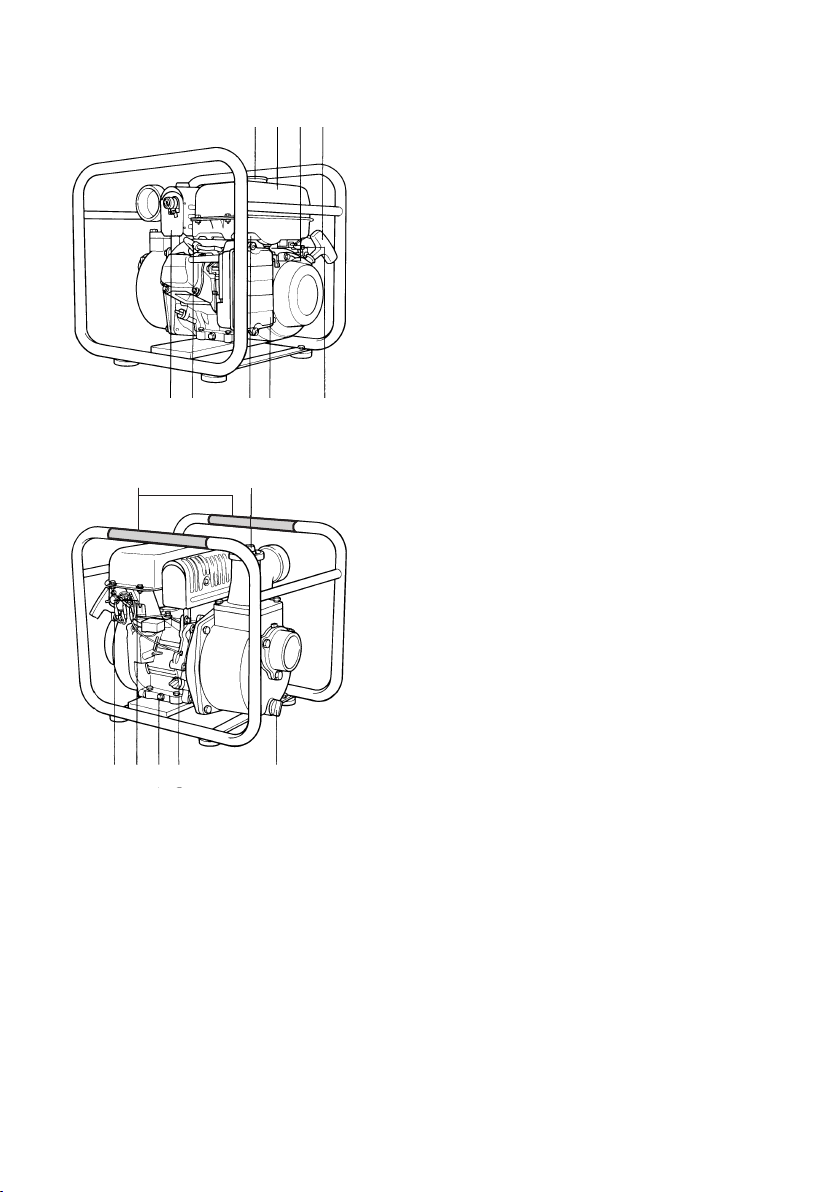
4321
1 Fuel tank cap
2 Fuel tank
3 Fuel cock
4 Recoil starter
5 Throttle lever
6 Air filter case cover
7 Choke lever
8 Spark plug
9 Muffler
0 Priming plug
q Water drain plug
56789
0y
w Oil filler cap
e Oil drain bolt
r Engine switch
t Oil warning light
y Carrying handle
DESCRIPTION
t r e w q
– 4 –
CONTROL FUNCTION
Oil warning light (Red)
When the oil level falls below the lower level, the oil
warning light comes on and then the engine stops
automatically. Unless you refill with oil, the engine will
not start again.
TIP
If the engine stalls or does not start, turn the engine
switch to “ON” (ON) and then pull the recoil starter. If
the oil warning light flickers for a few seconds, the
engine oil is insufficient. Add oil and restart.
Engine switch
The engine switch controls the ignition system.
2
1 “ON” (ON)
Ignition circuit is switched on.
The engine can be started.
1
2 “OFF” (OFF)
Ignition circuit is switched off.
The engine will not run.
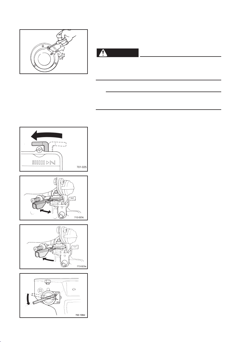
Throttle lever
The throttle lever controls the engine speed. Move the
throttle lever in direction 2 to increase engine speed.
Move the throttle lever in direction 1 to decrease
engine speed.
a
1
2
a Throttle lever
NOTICE
Always check throttle operation before starting the
engine.
– 5 –
Fuel cock lever
The fuel cock supplies fuel from the fuel tank to the
carburetor.
2
1
The fuel cock has two positions.
1 ON
With the lever in this position, fuel flows to the carburetor. Normal using is done with the lever in this position.
2 OFF
With the lever in this position, fuel will not flow. Always
turn the lever to this position when the engine is not
running.
1
Choke lever
Starting a cold engine requires a richer air-fuel mixture, which is supplied by the choke lever.
1 Choke lever
1
Recoil starter
The recoil starter is used to start the engine.
Pull the recoil starter slowly until it is engaged, then
pull it briskly.
704-010
1 Recoil starter handle
NOTICE
9 Pull the recoil starter handle straight.
9 Return the recoil starter handle slowly.
9 Do not touch the recoil starter handle while the
water pump is operating.
– 6 –
PREPARATION
WARNING
Fuel
9 Fuel is hig h ly flammable and poisonous.
Check “SAFETY INFORMATION” (See page 1)
carefully before filling.
9 Do not overfill the fuel tank, otherwise it may
overflow when the fuel warms up and expands.
9 Wipe up any spilled fuel immediately.
9 After fill the fuel, make sure the fuel tank cap is
tightened securely.
707-041
1. Stop the engine.
2. Place the water pump on a level surface.
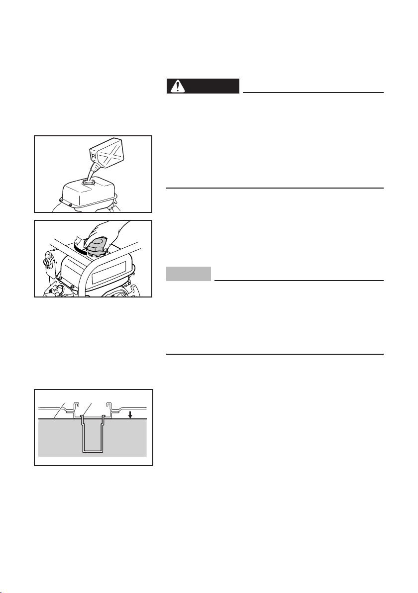
3. Remove the fuel tank cap.
4. Check the fuel level.
5. If low, fill the tank with fuel.
NOTICE
9 Immediately wipe off spilled fuel with a clean,
dry, soft cloth, since fuel may deteriorate paint-
ed surfaces or plastic parts.
9 Use only unleaded gasoline. The use of leaded
gasoline will cause severe damage to internal
engine parts.
1
2
707-037
Make sure there is sufficient fuel in the tank.
When refueling, be sure to fill the tank up to the bottom edge of the fuel tank filter.
1 Fuel level
2 Fuel tank filter
Your Yamaha engine has been designed to use regular
unleaded gasoline with a pump octane number ((R +
M)/2) of 86 or higher, or research octane number of 91
or higher.
– 7 –
Recommended fuel:
Unleaded gasoline
Fuel tank capacity:
Total:
4.0 L (1.06 US gal, 0.88 Imp gal)
Engine oil
NOTICE
The water pump has been shipped without engine
oil. Do not start the engine until you have filled it
with the sufficient engine oil.
1. Place the water pump on a level surface.
2. Remove the oil filler cap.
1 Oil filler cap
1
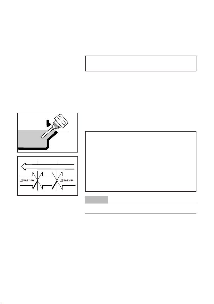
3. Fill the specified amount of the recommended
engine oil, and then install and tighten the oil filler
cap.
700-006
2
700-110
2 Correct level
– 8 –
0˚C
å
YAMALUBE 4 (10W-40)
ç
SAE #20
32˚F
25˚C
80˚F
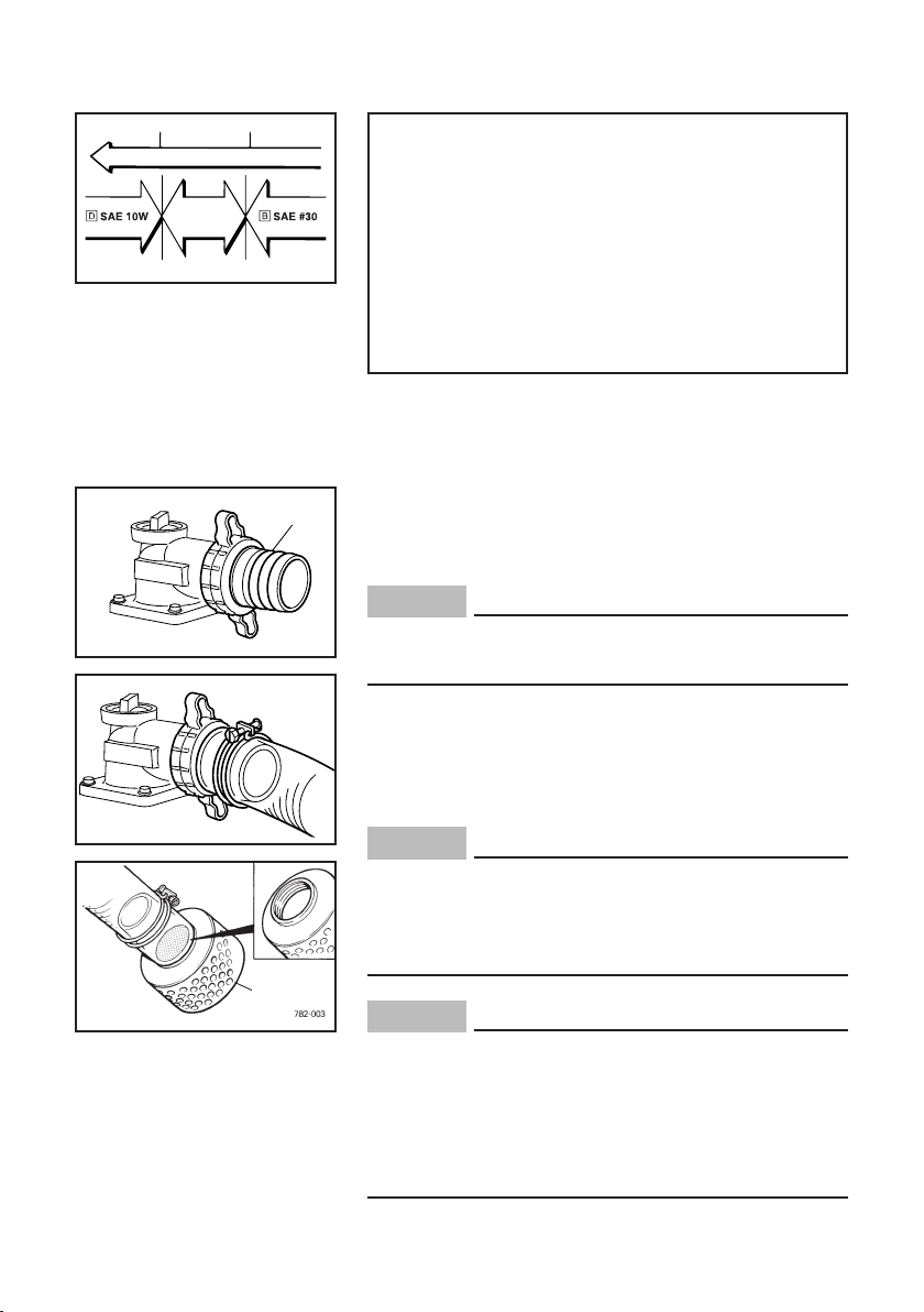
Recommended engine oil:
å YAMALUBE 4 (10W-40),
SAE 10W-30 or 10W-40
∫ SAE #30
ç SAE #20
∂ SAE 10W
Recommended engine oil grade:
API Service SE type or higher
Engine oil quantity:
0.6 L (0.63 US qt, 0.53 Imp qt)
1
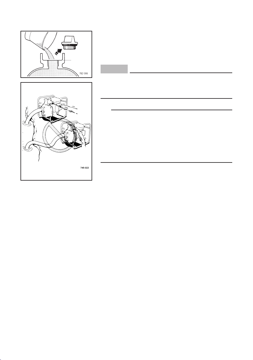
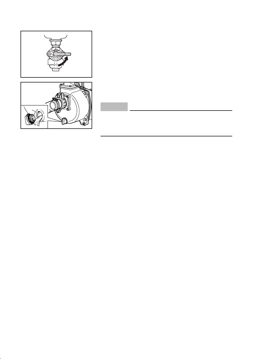
1. Install the hose joint to the pump.
1 Hose joint
NOTICE
Water hose installation
When installing the joint to the pump, be sure the
gasket is in place.
2. Connect the hoses on the joints with clamp.
3. Connect the strainer on the inlet hose end.
2 Strainer
NOTICE
9 Be sure the hoses are installed securely or air
leak will occur and water will not be drawn up.
9 Be sure the strainer is installed or pump dam-
age may occur.
2
NOTICE
Install the strainer
A) 50 mm (2 in) suction port diameter for YP20G
or
B) 80 mm (3 in) suction port diameter for YP30G
both with filtering perforations 8 mm (0.31 in) or
less in diameter.
– 9 –
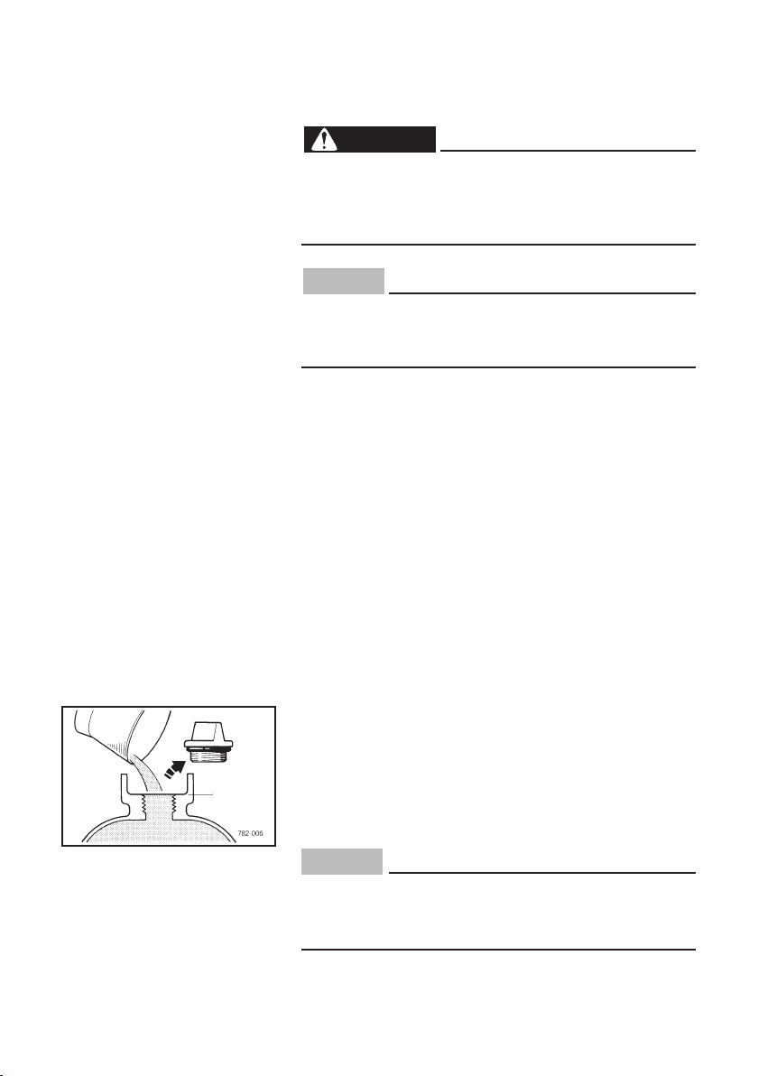
Water priming
Make sure the water is at pump casing upper level.
Add water as necessary.
1
1 Upper level
NOTICE
Be sure the pump is filled up with water before
starting the engine or mechanical seal damage will
occur.
TIP
9 Place the water pump on a secure, flat and level
surface as near to the water to be pumped as possible.
9 The higher the water pump is from the water sur-
face (more suction head), the longer it will take to
prime and the lesser pump output (discharge
head) will be.
– 10 –

PRE-OPERATION CHECK
WARNING
If any item in the Pre-operation check is not working properly, have it inspected and repaired before
operating the water pump.
The condition of a water pump is the owner’s responsibility. Vital components can start to deteriorate quickly
and unexpectedly, even if the water pump is unused.
TIP
Pre-operation checks should be made each time the
water pump is used.
Pre-operation check
Fuel (See page 7)
9 Check fuel level in fuel tank.
9 Refuel if necessary.
Fuel line
9 Check fuel hose for crack or damage.
9 Replace if necessary.
Engine oil (See page 8)
9 Check oil level in engine.
9 If necessary, add recommended oil to specified
level.
9 Check water pump for oil leakage.
The point where abnormality was recognized by
use
9 Check operation.
9 If necessary, consult a Yamaha dealer.
– 11 –
OPERATION
WARNING
Never operate the water pump in a closed area or it
may cause unconsciousness and death within a
short time. Operate the engine in a well ventilated
area.
NOTICE
The water pump has been shipped without engine
oil. Do not start the engine until you have filled it
with the sufficient engine oil.
Preparation for operation
Choose the best location for the water pump to perform the pumping job. Place the pump on a flat, level
surface as near as possible to the water to be pumped.
Connect the hoses properly (See page 9).
Pumping performance is affected by various factors
including the length of the hoses and the vertical
height from the water surface to the pump (suction
head) and from the pump to the end of the discharge
hose (discharge head). As the height of the pump from
the water surface increases the time necessary to
prime the pump will increase and the discharge from
the pump will decrease. Do not exceed maximum Total
head and Suction head specifications for your water
pump (See page 30).
Water priming
Before starting the engine, make sure water is at the
pump casing upper level.
1
Add clean water as necessary.
1 Upper level
NOTICE
Be sure the pump is filled up with water before
starting the engine or mechanical seal damage will
occur.
– 12 –
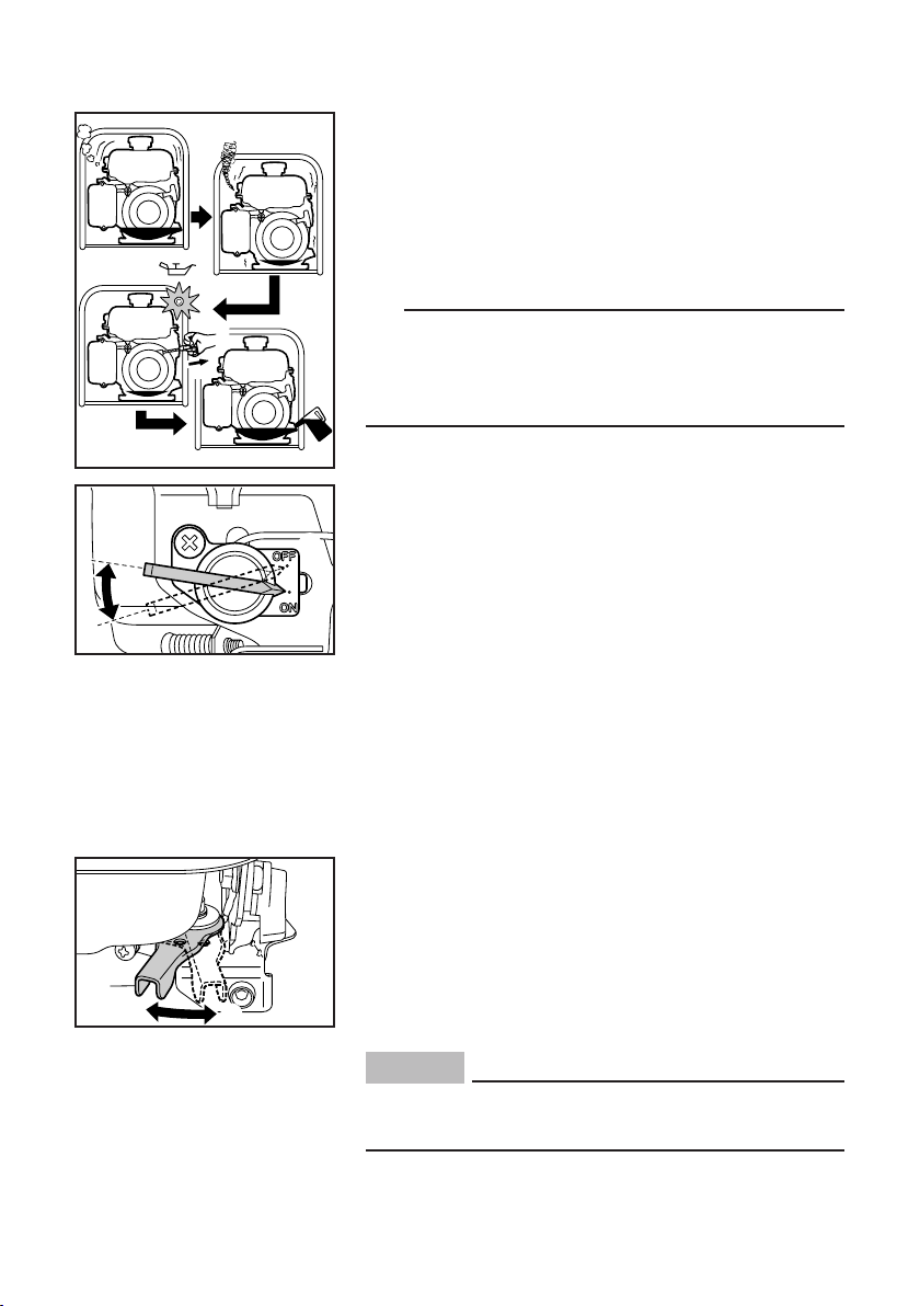
Starting the engine
NOTICE
Be sure the pump is filled up with water before
starting the engine.
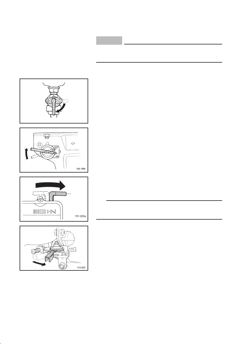
1. Turn the fuel cock lever to the ON.
1 ON
1
705-037
2. Turn the engine switch to the “ON” (ON).
2 “ON” (ON)
2
1
3. Turn the choke lever to the “1”.
3
3 Choke lever
TIP
The choke is not required to start a warm engine.
Turn the choke lever to the operating position.
4. Move the throttle lever slightly to right.
– 13 –
5. Pull the recoil starter slowly until it is engaged,
WARNING
then pull it briskly.
704-010
the recoil starter handle can be drawn back quickly
by the engine kickback.
TIP
Grasp the carrying handle firmly to prevent the water
pump from falling over when pulling the recoil starter.
6. After the engine starts, warm up the engine until
the engine does not stop when the choke lever is
Be careful to use the recoil starter. In rare cases,
4
returned to the original position.
4 Original position
7. Set the throttle lever in desired position.
5 Increase engine speed
6 Decrease engine speed
6
5
Stopping the engine
1. Move the throttle lever fully to left.
2. Turn the engine switch to the “OFF” (OFF).
1
1 “OFF” (OFF)
– 14 –
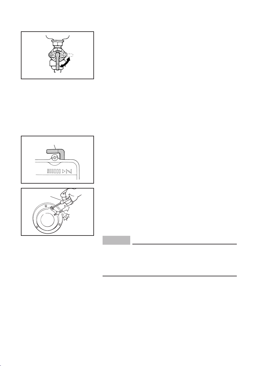
3. Turn the fuel cock lever to the OFF.
2 OFF
2
705-038
Drain water after use
After use, open the drain plug to drain remaining water
from the casing.
1
NOTICE
Unless the casing is drained before storage, the
pump can be severely damaged by freezing water
if temperatures drop to 0 °C (32 °F) or below.
1 Drain port
High altitude operation
This engine may require a high altitude carburetor kit
to ensure correct engine operation at altitudes above
4000 ft. (1219 meters). If you operate your engine at
altitudes above 4000 ft. (1219 meters) consistently,
have your local Yamaha dealer perform the necessary
carburetor modification. This engine should be operated in its original configuration below 4000 ft. (1219
meters) as damage may occur if high altitude carburetor kit is installed and operated below 4000 ft. (1219
meters).
– 15 –
PERIODIC MAINTENANCE
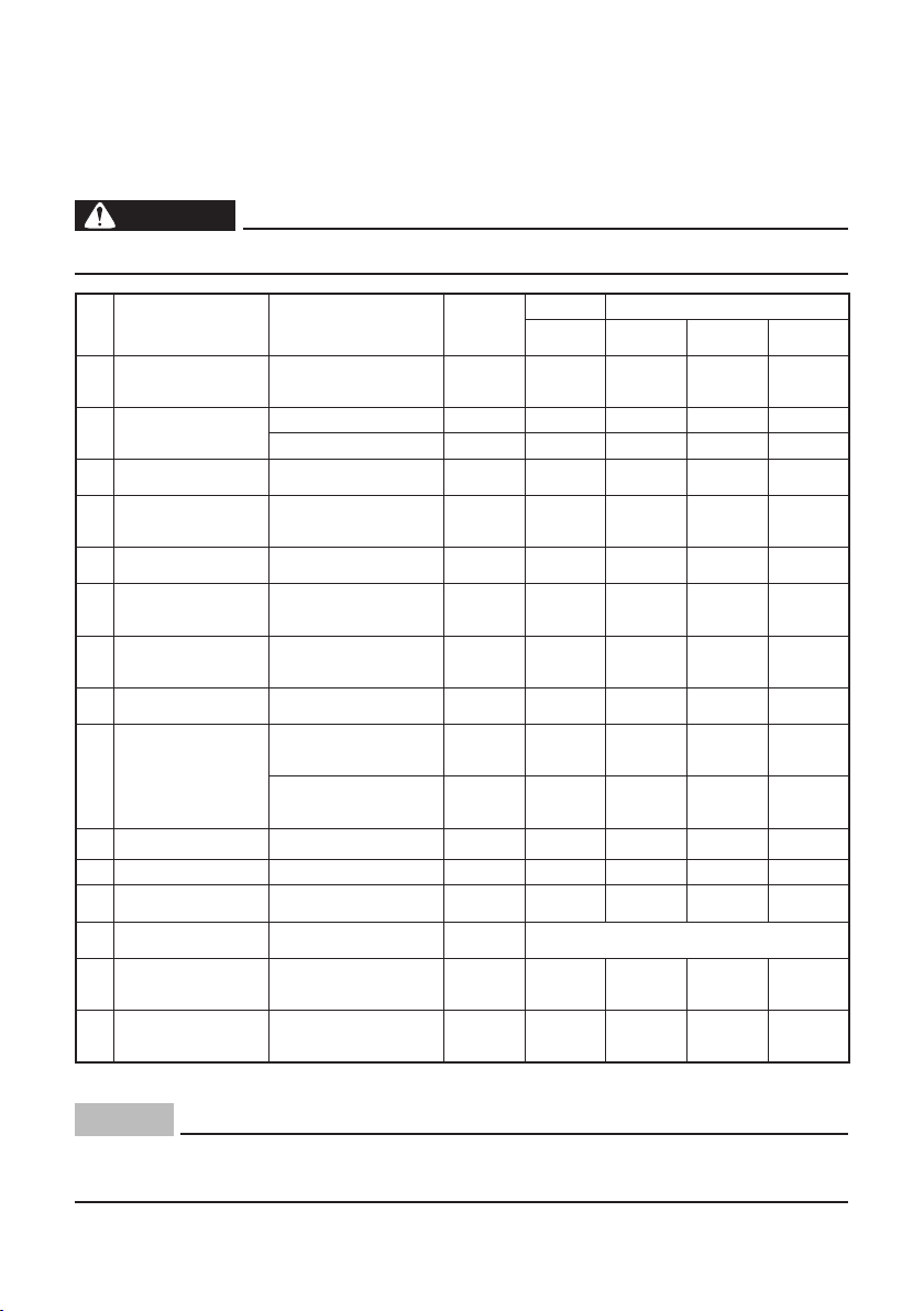
Maintenance chart
Regular maintenance is most important for best performance and safe operation.
WARNING
Stop the engine before starting maintenance work.
No. Item Remarks
**
1.
Spark plug
2. Engine oil
**
3.
Air filter
4. Fuel tank filter
**
5.*
Valve clearance
6. Fuel line
**
Crankcase
7.*
breather system
**
8.*
Idle speed
**
9.
Exhaust system
**
10.
Choke lever
11.* Cooling system Check fan damage.
12. Starting system
**
13.*
Decarbonization
14. Water pump
15.* Fittings/Fasteners
* : It is recommended that these items be serviced by a Yamaha dealer.
** : Related to emission control system.
Check condition,
adjust gap and clean.
Replace if necessary.
Check oil level.
Replace.
Clean.
Replace if necessary.
Clean fuel cock and
fuel tank filter.
Replace if necessary.
Check and adjust
when engine is cold.
Check fuel hose for
cracks or damage.
Replace if necessary.
Check breather hose
for cracks or damage.
Replace if necessary.
Check and adjust
engine idle speed.
Check for leakage.
Retighten or
replace gasket if necessary.
Check muffler screen and
spark arrester. Clean or
replace if necessary.
Check choke operation.
Check recoil starter
operation.
More frequently if
necessary.
Check for leakage.
Retighten or replace
O-ring and/or gasket.
Check all fittings and
fasteners.
Correct if necessary.
Pre-opera-
tion check
(daily)
7
7
7
7
7
7
Initial Every
1 month or
20 Hr
3 month or
50 Hr
7
7 7
7
After every 500 Hrs.
6 month or
100 Hr
7
7
7
12 month or
300 Hr
7
7
7
7
NOTICE
Use only Yamaha specified genuine parts for replacement. Ask an authorized
Yamaha dealer for further attention.
– 16 –
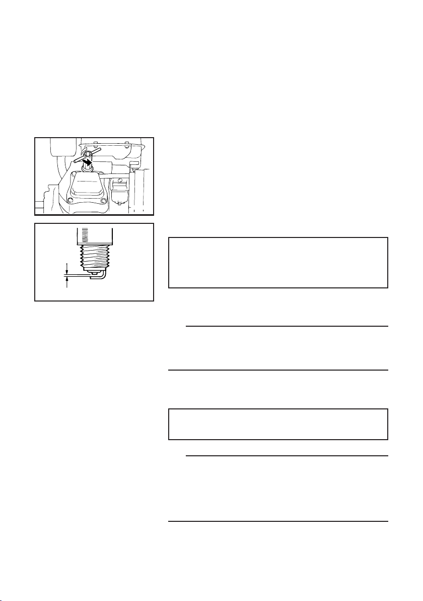
Spark plug inspection
The spark plug is an important engine component,
which should be checked periodically.
1. Remove the spark plug cap and the spark plug.
2. Check for discoloration and remove the carbon.
The porcelain insulator around the center elec-
trode of spark plug should be a medium-to-light
760-005a
a
760-001a
tan color.
3. Check the spark plug type and gap.
Standard spark plug:
BPR4ES (NGK)
Spark plug gap:
0.7–0.8 mm (0.028–0.031 in)
a Gap
TIP
The spark plug gap should be measured with a wire
thickness gauge and, if necessary, adjusted to specification.
4. Install the spark plug, and then tighten it.
Spark plug tightening torque:
20 Nm (2.0 m·kgf, 14 ft·lbf)
TIP
If a torque wrench is not available when installing a
spark plug, a good estimate of the correct torque is
1/4–1/2 turn past finger tight. However, the spark plug
should be tightened to the specified torque as soon as
possible.
5. Install the spark plug cap.
– 17 –
Carburetor adjustment
The carburetor is a vital part of the engine. Adjusting
should be left to a Yamaha dealer with the professional
knowledge, specialized data, and equipment to do so
properly.
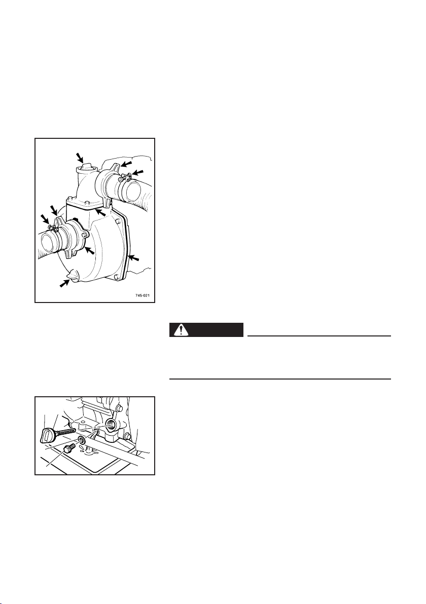
Water leakage check
Check for water leakage from water pump.
Retighten the bolts, plugs, band, and hose joints.
Replace O-rings and/or gaskets if necessary.
Engine oil replacement
WARNING
Avoid draining the engine oil immediately after
stopping the engine. The oil is hot and should be
handled with care to avoid burns.
3
1. Place the water pump on a level surface and warm
4
1
up the engine for several minutes. Then stop the
engine and turn the fuel cock lever to OFF.
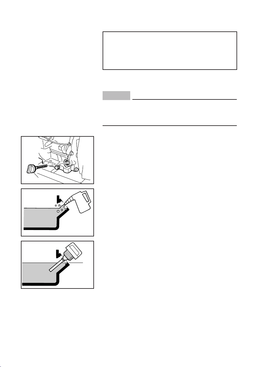
2. Remove the oil filler cap.
2
1 Oil filler cap
3. Place an oil pan under the engine. Remove the oil
drain bolt and the gasket so that the oil can be
completely drained.
2 Oil drain bolt
3 Gasket
4 O-ring
– 18 –
4. Check the oil drain bolt, the oil filler cap and the
O-ring. Replace them if damaged.
5. Install a new gasket and the oil drain bolt and then
tighten the bolt.
Oil drain bolt tightening torque:
17 Nm (1.7 m·kgf, 12 ft·lbf)
6. Add engine oil to the correct level.
0˚C
å
YAMALUBE 4 (10W-40)
ç
SAE #20
32˚F
25˚C
80˚F
5
700-110
5 Correct level
Recommended engine oil:
å YAMALUBE 4 (10W-40),
SAE 10W-30 or 10W-40
∫ SAE #30
ç SAE #20
∂ SAE 10W
Recommended engine oil grade:
API Service SE type or higher
Engine oil quantity:
0.6 L (0.63 US qt, 0.53 Imp qt)
NOTICE
Be sure no foreign material enters the crankcase.
7. Install the oil filler cap.
– 19 –
 Loading...