

Page 1
CONCERT GLOCKENSPIEL
YG2500
取扱説明書 / OWNER’S MANUAL
このたびは、ヤマハグロッケンシュピールをお買い
上げいただきまして、誠にありがとうございます。
ご使用の前にこの取扱説明書をお読みいただき、
末永くご愛用ください。
Thank you for purchasing a YAMAHA Glockenspiel.
Before using this instrument we urge you to read
this Owner’s Manual thoroughly, and keep it in a
safe place for later reference.
組立ての前に、P.2「安全へのこころがけ」、P.3「ガススプリング取り扱いに関する注意事項」、P.4「末永くご使
用いただくために」、P.6「部品の確認」を必ずお読みください。
Before starting assembly, be sure to read the following sections; “PRECAUTIONS FOR HANDLING GAS
SPRING” pg 16, “TO GET THE MOST OUT OF YOUR INSTRUMENT” pg 17, “Parts Checklist” pg 19.
Page 2
PRECAUTIONS FOR HANDLING GAS SPRING
Please observe the following instructions for proper handling of the gas spring.
1. Precautions for handling the gas spring
This gas spring requires no oil supply to its sliding section. Additional oil will reduce the sealing durability and cause the oil to leak.
Never apply any impact to the gas spring. It will cause oil leakage, malfunction or breakage.
Never disassemble the gas spring. As a high pressure gas is sealed in it, disassembling it will cause
a high risk.
Note that there is not much rigidity in the bending direction. Depending on accuracy in its installation,
the bending load will cause the rod to bend, resulting in malfunction.
Note that a nick on the piston rod or cylinder will shorten the service life of the sealing or cause a
malfunction.
Do not expose the gas spring to an excessively high or low temperature. The allowable temperature
range for use is -20°C to 80°C.
Avoid using the instrument where it is exposed to to rain, water or much dust.
Do not apply an excessive force to lift the frame end and pull off the gas spring from the leg.
● Do not apply a high tensile load to the gas spring as it will cause damage to the gas spring.
●
In the event of a failure, stop using the instrument and contact the shop of its
CAUTION
purchase. If your dealer is unable to assist you, please contact Yamaha directly.
2. Instructions for discarding the gas spring
Make sure to observe the following instructions when discarding the gas spring.
As pressurized nitrogen gas is sealed in the gas spring, be sure to release before discarding it. Or an
explosion may occur, causing an injury.
DANGER
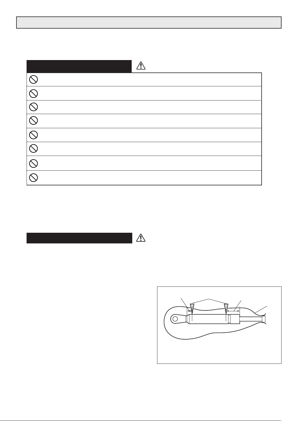
[PRECAUTIONS]
A. Do not crash.
B. Do not cut.
C. Do not make a hole anywhere other than the
specified positions (q and w in the Fig.1).
D. Do not throw it in the fire.
Fig. 1
15mm
Drill
q
w
35mm
Plastic bag
[Discarding procedure]
1. Put the gas spring in a plastic bag. Using a drill of 2 to
3 mm, make a hole q from outside of the plastic bag
at the position as specified in the figure to release the
gas and oil and then make a hole w at the position
as specified. (Be sure to make holes in the order
of q and w. )
2. If a plastic bag is not used, the oil and drill chips will
spread. (In such a case, wear eye protection
glasses. )
* Drill 2 holes as shown above to release the
gas before discarding the gas spring.
16
Page 3

TO GET THE MOST OUT OF YOUR INSTRUMENT
Please read the following instructions carefully before using your glockenspiel.
◆ Installation Location
Use or storage in the following locations may cause damage, even when packaged.
• In direct sunlight, such as near a window, or in a closed vehicle in daytime.
• Near heating devices or in other locations subject to excessive heat.
• In excessively cold environment.
• In places with excessive humidity or dust.
• Locations subject to vibrations.
◆ Handling
• Placing objects on or leaning against the instrument can damage the tone bars or the side frame.
This can also lead to the instrument falling over, etc. as described in the “Precautions” section. Never
do this as it is very dangerous.
• Do not use the glockenspiel’s mallets on a vibraphone, metalphone, etc. It can dent the tone bars or
cause damage, which can result in poor pitch.
◆ Transporting the Instrument
• When transporting the disassembled instrument, remove the tone bars and resonator pipes from the
glockenspiel and wrap them in a soft blanket, etc. for transport.
• When moving the instrument with its casters, make sure you adjust the instrument’s height to its
lowest level. This puts the instrument’s center of gravity at a lower point for greater stability while
moving.
• The instrument is sensitive to impacts. Treat the instrument with care when moving. Never drop or
throw the instrument.
• If it is necessary to lift the instrument while moving it, always do so with at least two persons and
using both hands to hold the side frames or legs. The instrument weighs about 36 kilograms.
◆ Maintenance
• The tone bars should be polished from time to time using a soft and dry cloth. Never use thinner or
benzene or a wet cloth for cleaning purpose.
◆ Keep This Manual for Future Reference
• After reading, make sure to keep the manual in a safe place.
Assembly Cautions
• When assembling/disassembling the instrument, make sure to follow the procedure outlined in this
manual. Assembly in the wrong order can cause the pipes to drop which may result in an injury,
impair the performance functionality of the instrument or cause noise.
• After final adjustment of the legs the fixing screws must be tightened securely to prevent loosening.
Looseness may cause the instrument to shift during performance and can also cause noise and
other problems. Retighten the screws from time to time.
17
Page 4
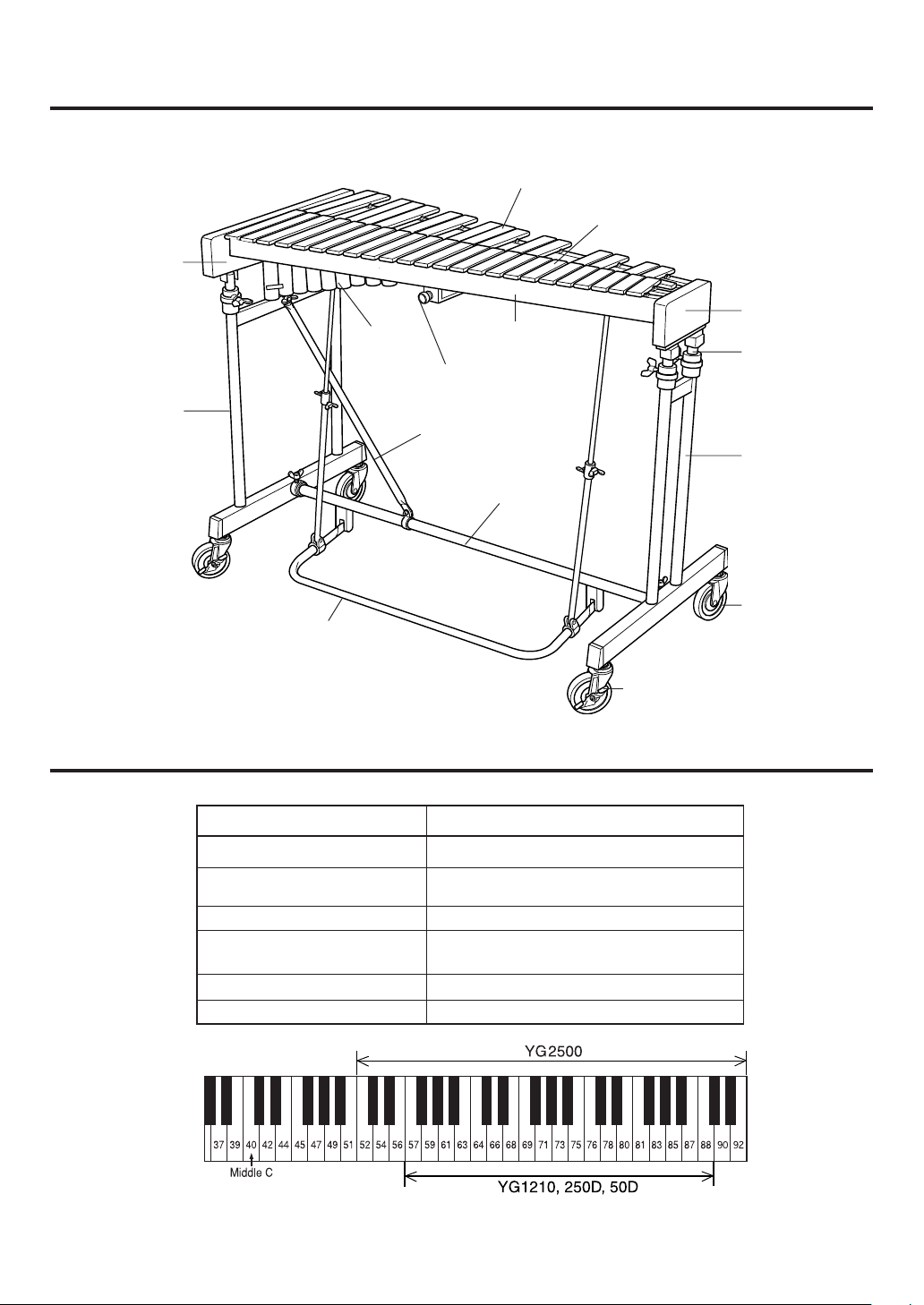
Nomenclature
Side frame
(low register side)
Legs
(low register side)
Pedal
Resonator
pipes
Accidental tone bars
Long frame
Pedal stopper
Leg stay
Pedal stay assembly
Natural tone bars
Side frame
(high register side)
Slide legs
Legs
(high register side)
Caster
Specifications
Pitch Range
Tone Bar Material/Support
Tone Bar Width/Thickness
Dimensions (WxDxH)
Weight
Accessories
Stopper
YG2500
C52-E92 (3 1/2 octaves)
High Carbon Steel Tone Bars/Mounted with
strings through holes drilled through the sides
32.5mm/9mm
106.2cm x 56.4cm x 85-105cm
(41-3/4" x 22" x 33-1/2"-44-3/8")
36kg (79 lbs)
None
(reference)
18
* Please note that specifications and/or design may change without notice.
Page 5

Parts Checklist
The following parts are included in the YG2500 package.
Before assembling the instrument, make sure that all parts are present
and accounted for.
* If any parts are missing, please contact the dealer from whom you purchased the
instrument.
q Glockenspiel main unit
(consisting of the side assemblies, tone bars, and resonators).
CAUTION
Do not remove the glockenspiel’s main unit from the
package until you are ready to start Step 2 “Attach the
main unit of the glockenspiel to the legs” described on
page 22. As the resonator pipes are already attached to
the main unit, it will be unstable if placed on the floor,
which can be very dangerous in addition to causing
damage to the frame and pipes.
w Legs (low register side) e Leg (high register side)
r Pedal stay assembly
y Main unit fixing knobs x3
t Center rods x2
u Owner’s Manual (this booklet) x1
19
Page 6

Assembly
For safety reasons, assembly should be performed with at least two persons and in a sufficient amount of space.
To protect the instrument from damage, we recommend that you
assemble it on a carpet, soft cloth, etc., placed on a flat surface.
1 Connect the pedal stay assembly to both legs (low register and high register sides).
* Make sure that the slide guide fixing bolts on both legs are tightened firmly before performing this operation.
CAUTION
Leg (low register side) Leg (high register side)
Do not loosen the slide guide fixing bolts at this point. Doing so will result in
the legs suddenly rising. This can be extremely dangerous!
Slide guide fixing bolts
1-1 Position the pedal stay assembly and low and high register side leg assemblies as shown in the
illustration below.
Leg
(low register side)
20
Low register side
Pedal stay assembly
Performer side
Leg
(high register side)
High register side
Page 7

Assembly
1-2 Position the pedal stay so the indentation is facing up, and insert the pedal stay all the way into the
receiver (low register side) on the leg (at this point, the wing bolt’s end is aligned with the indentation on the pedal stay), then tighten the wing bolt to secure.
Attach the pedal stay assembly to the high register side in the same manner.
* Use the hole close to the indentation as a reference for aligning the pedal stay.
Wing bolt
Wing bolt
Use this hole for aligning
Pedal stay
Indentation
Receiver
(low register side)
The illustration shows attachment of the pedal
stay to the low register side.
Pedal stay
Leg
(low register side)
Indentation
1-3 After confirming that both right and left legs are standing vertically, attach one end of the leg stay
that is attached to the pedal stay, onto the leg (low register side) using the wing nut located
between the two upright legs, and tighten the wing nut to secure.
* Slide the end of the stay firmly onto the bolt.
Leg
(low register side)
End of leg stay
Leg stay
Wing nut
21
Page 8

Assembly
2 Attach the main unit of the glockenspiel to the legs.
CAUTION
The glockenspiel is heavy so make sure that two persons carry out the operation.
Also, take care not to pinch your fingers between the glockenspiel and the legs.
2-1 Lock the caster stoppers on either side so that the legs do not move about during the assembly.
2-2 Align the holes (two holes on each side) located on the underside of the side frames with the guide
pins on the top of the legs and then place the glockenspiel main unit onto the legs.
* If the guide pins can not be aligned with the holes on the underside of the side frames, temporarily discon-
nect the leg stay and try again.
Glockenspiel
Side frame
Guide pin Side frame
Guide pin
Leg stay
22
Stopper
Stopper
2-3 Use the fixing knobs (supplied) to secure the legs to the right and left side frames (two locations on
the low register side and one location on the high register side).
High register
side
Low register
side
Fixing knobs
Fixing knob
Page 9

2-4 Connect the center rod to the damper receiver.
* This operation must be carried out on both low and high register sides.
Assembly
2-4-1
Loosen the center rod wing bolts (two locations) and insert the center rod into the pedal rod.
Center rod
Center rod wing bolt
Center rod wing bolt
Pedal rod
2-4-2 While supporting the damper receiver with your hand, insert the end of the center rod into
damper receiver.
Damper receiver
The illustration shows the
attachment looking from the
Center rod
high register side.
2-4-3 Tighten the lock nut on the center rod to secure.
* When the nut becomes loose, or when the lock nut is set too high, the lock nut spring will be loose. This can
be a source of noise so take care and adjust properly.
Lock nut
Lock nut spring
23
Page 10

Adjustments
3 Adjustments
3-1 Pedal height adjustment
Loosen the center rod wing bolts (two each) on the right and left side center rods and hold the
pedal up to adjust the pedal height (the space between the bottom of the pedal and the floor).
After determining the height, hold the pedal and tighten the center rod wing bolts (two each) on
both right and left side center rods.
* 2-3cm of space between the bottom of the pedal and the floor should be adequate.
Center rod wing bolts
Pedal
Loosen the center rod wing bolts Hold here while tightening the
Center rod wing bolts
center rod wing bolts
3-2 Damper Adjustment
3-2-1 Rotate the damper adjustment nut 2 (thinner nut) to the left to unlock the damper adjust-
ment nut 1 (thicker nut).
3-2-2 Rotate the damper adjustment nut 1 and adjust the damper (the amount of damper
applied to the tone bars).
Rotate the damper adjustment nut 1 to the left ............. Increases the amount of damper.
Rotate the damper adjustment nut 1 to the right .......... Decreases the amount of damper.
24
3-2-3 After damper adjustment is complete, tighten the damper adjustment nut 2 to lock the
damper adjustment nut 1.
* If the damper adjustment nut 2 is not tightened firmly, the damper adjustment nuts can drop off or cause
noise.
* A half damper effect can be obtained by lessening the amount of damper until the sound slightly sustains
even though the pedal is not depressed.
Damper adjustment nut 1
Damper adjustment nut 2
A
* If the space labeled “A” in the illustration is under
10mm, the damper stopper will not function properly. Make sure this space is more than 10mm.
Page 11

3-3 Using the damper stopper
Engaging the damper stopper, located on the performer side in the center of the long frame, holds
the damper open (letting the tone bars sustain) without having to continuously press the damper
pedal.
While holding the pedal down with your foot, press the stopper knob and remove your foot from the
pedal. The pedal remains in the lowered positioned and locked.
Press on the pedal again to automatically disengage the stopper and restore normal operation.
* If pedal height adjustment in step 3-1 “Pedal height adjustment” is set too low, the damper stopper may
not function properly. Please set the space between the bottom of the pedal and the floor to more than
2cm.
Adjustments
Damper stopper
The stopper slides in
between the adjustment nut
and the main unit to hold the
damper open.
4 Adjusting the tone bar height
CAUTION
Holding down both low and high register side side frames, loosen the slide guide fixing bolts.
After adjusting the instrument to a comfortable height, tighten the slide guide fixing bolts to secure. Use
the guide lines on the slide legs as a reference and adjust the height so that the instrument’s playing
surface is parallel to the floor.
After assembly is complete, make sure all nuts and bolts are tightened firmly.
When loosening the slide guide fixing bolts be sure to hold down the side frame
from above. The side frame can suddenly rise which is extremely dangerous.
Guide
lines
Slide guide fixing bolt
The brown felt attached to both sides of the glockenspiel’s main unit and the cardboard attached at two positions on the
low register side are part of the packing materials used to hold the tone bars in place. After assembly is complete, pull
on the felt and cardboard to remove.
25
Page 12

コンサートグロッケンシュピールYG2500
CONCERT GLOCKENSPIEL YG2500
ガススプリングについてのご説明
本製品におきましては、脚パイプ4本のうち2本にガ
ススプリングを装備しており、低音側は演奏者側、高
音側は演奏者の反対側に配置されております。
低音側のスライドガイド固定ネジを緩めると、ガスス
プリングの入っていない反対側の側板が多少下がりま
すが、これは故障ではありません。
高さ調整の際は、スライド脚に刻まれている目盛りを
参考に、音板と床面が平行になるよう調整してくださ
い。そのときは、ガススプリングの入っていない側の
側板を多少持ち上げていただく必要があります。
A Note on the Gas Springs
Two of the YG2500’s four legs are equipped with gas
springs. One on the low pitch end on the
performer’s side and another on the high pitch end
on the audience side.
When loosening the slide guide bolts on the low
pitch end legs, the side of the frame not equipped
with the gas spring will be slightly lower however; this
is normal and not a sign of any problem.
When adjusting instrument height, use the guide
lines on the slide legs as a reference and adjust the
height so that the tone bars are parallel with the floor.
At this time, it will be necessary to slightly lift the side
of the frame without gas springs.
ガススプリングなし
Without gas springs
ガススプリング内蔵
Equipped with gas springs
目盛り
Guide lines
スライドガイド固定ネジ
Slide guide fixing bolt
 Loading...