

Page 1

2011
SERVICE MANUAL
YFM90RA
43D-F8197-12LIT-11616-24-16
Page 2

EBS00001
YFM90RA
SERVICE MANUAL
©2010 by Yamaha Motor Corporation, U.S.A.
First edition, July 2010
All rights reserved.
Any reproduction or unauthorized use
without the written permission of
Yamaha Motor Corporation, U.S.A.
is expressly prohibited.
Printed in U.S.A.
LIT-11616-24-16
Page 3
EBS00002
IMPORTANT
This manual was produced by the YamahaMotorCompany primarily for use by Yamaha dealers and
their qualified mechanics. It is not possible to include all the knowledge of a mechanic in one manual, so it is assumed that anyone who uses this book to perform maintenance and repairs on
Yamaha machine has a basic understanding of the mechanical ideas and the procedures of
machine repair. Repairs attempted by anyone without this knowledge are likely to render the
machine unsafe and unfit for use.
Yamaha Motor Company, Ltd. is continually striving to improve all its models. Modifications and significant changes in specifications or procedures will be forwarded to all authorized Yamaha dealers
and will appear in future editions of this manual where applicable.
TIP
Designs and specifications are subject to change without notice.
EBS00003
IMPORTANT INFORMATION
Particularlyimportant information is distinguished in this manual by the following notations:
This is the safety alert symbol. It is used to alert you to potential
personal injury hazards. Obey all safety messages that follow this
symbol to avoid possible injury or death.
WARNING
NOTICE
TIP
* Product and specifications are subject to change withoutnotice.
A WARNING indicates a hazardous situation which, if not avoided,
could result in death or serious injury.
A NOTICE indicates special precautions that must be taken to avoid
damage to the vehicle or other property.
A TIP provides key information to make procedures easier or clearer.
Page 4
EBS00004
HOW TO USE THIS MANUAL
MANUAL ORGANIZATION
This manual consists of chapters for the main categories of subjects. (See “symbols”)
1st title : This is the title of the chapter with its symbol in the upper right corner of each page.
2nd title : This title indicates the section of the chapter and only appears on the first page of each
section. It is located in the upper left corner of the page.
3rd title : This title indicates a sub-section that is followed by step-by-step procedures accompanied by corresponding illustrations.
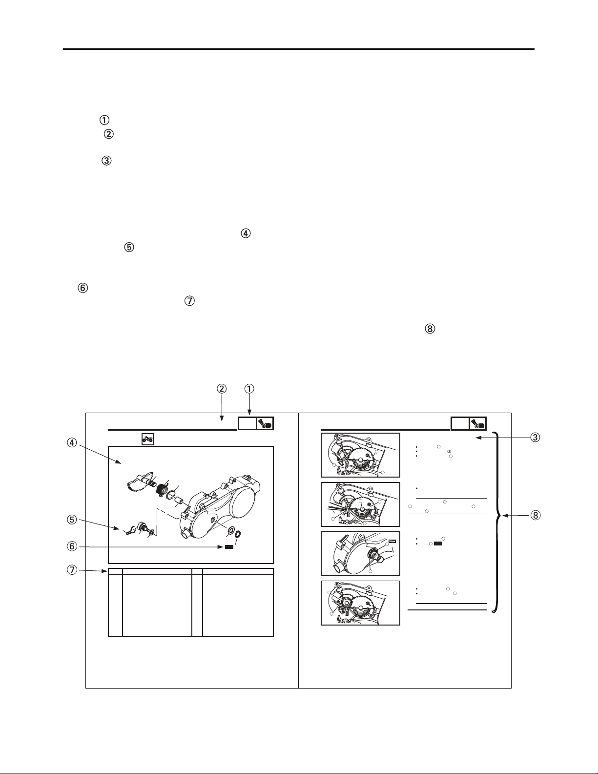
EXPLODED DIAGRAMS
To help identify parts and clarify procedure steps, there are exploded diagrams at the start of each
removal and disassembly section.
1. An easy-to-see exploded diagram is provided for removal and disassembly jobs.
2. Numbers are given in the order of the jobs in the exploded diagram. A number that is enclosed
by a circle indicates a disassembly step.
3. An explanation of jobs and notes is presented in an easy-to-read way by the use of symbol marks
. The meanings of the symbol marks are given on the next page.
4. A job instruction chart accompanies the exploded diagram, providing the order of jobs, names
of parts, notes in jobs, etc.
5. For jobs requiring more information, the step-by-step format supplements are given in addition
to the exploded diagram and the job instruction chart.
EAS00338
KICKSTARTER
1
Removing the kickstarter
Crankcase, cover
Kick pinion gear clip
1
Kick pinion gear
2
Washer
3
Circlip
4
Washer
5
Kick shaft assembly
6
Torsion spring
7
Spacer
8
Solid bush
9
BELT DRIVE
6
7
8
9
2
3
Remove the parts in the order listed.
Refer to “CRANKCASE COVER “.
Refer to “INSTALLING THE KICKSTARTER“.
1
1
1
1
1
1
1
1
1
For installation, reverse the removal procedure.
4 - 32
ENG
2
3
c
5
New
4
RemarksOrder Job/Part Q’ty
1
2
1
b
a
d
2
1
BELT DRIVE
EAS00340
INSTALLING THE KICKSTARTER
1. Install:
solid bush
kickstarter shaft
kickstarter spring
2. Hook:
kickstarter spring
TIP
Hook the spring end on the kickstarter shaft
b
as shown, and hook the other end on the
projection .
3. Install:
plain washer
circlip
4. Install:
kick pinion gear
kick pinion gear clip
TIP
Install the clip at the position shown.
4 - 33
ENG
1
3
a
d
1
New
2
c
1
2
Page 5
GEN
INFO
CHK
ADJ
CARB
SPEC
ENG
CHAS
EBS00005
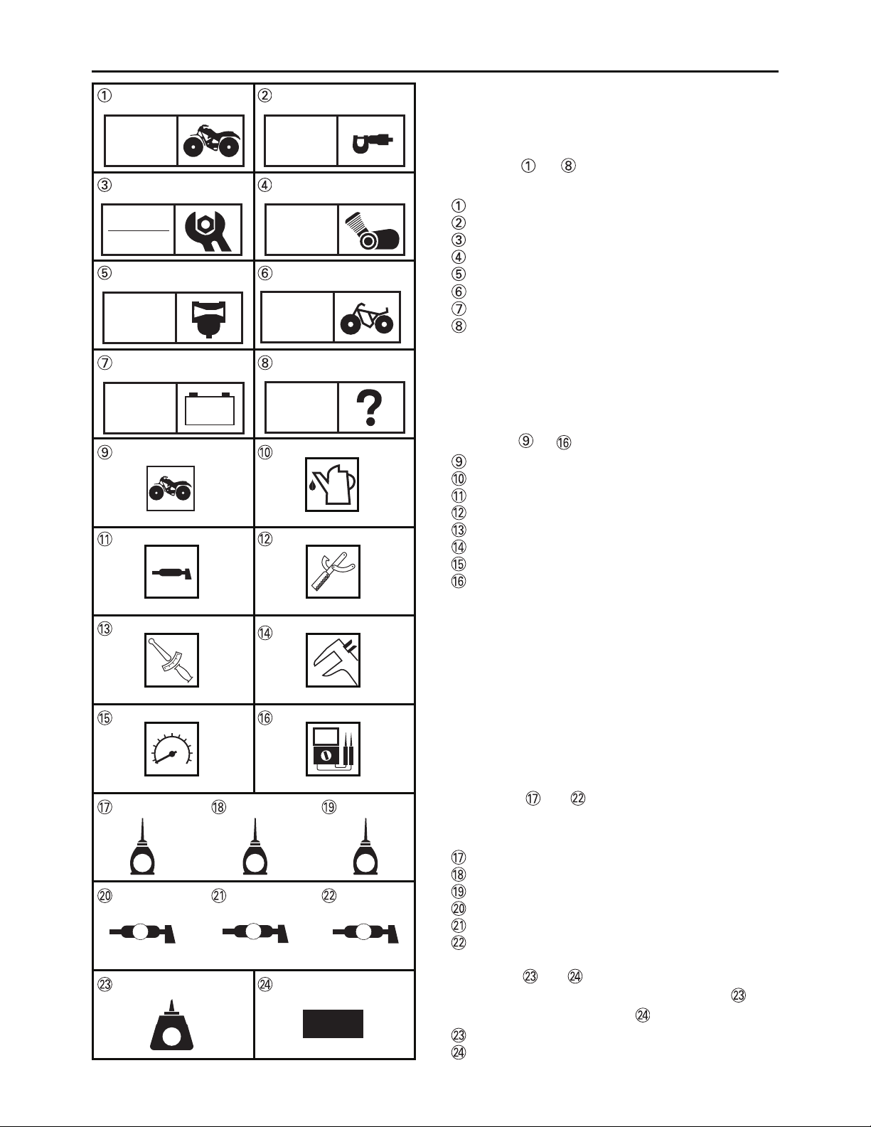
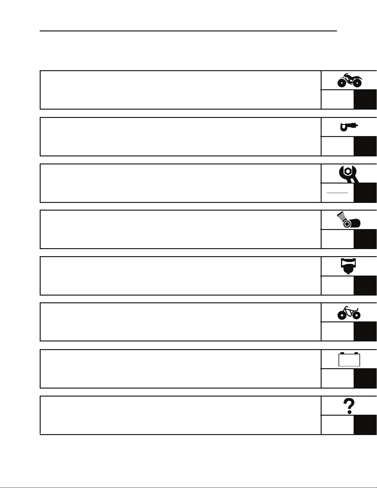
SYMBOLS
The following symbols are not relevant to
every machine.
Symbols to indicate the subject of each
chapter.
General information
Specifications
Periodic checks and adjustments
Engine
Carburetor
Chassis
Electrical
Troubleshooting
ELEC
E
B
– +
T
.
R
.
TRBL
SHTG
G
LS
Symbols to indicate the following.
Serviceable with engine mounted
Filling fluid
Lubricant
Special tool
Torque
Wear limit, clearance
Engine speed
Electrical data (Ω, V, A)
Symbols to in the exploded diagrams
indicate the types of lubricants and lubrication
points.
M
M
Apply engine oil
Apply gear oil
Apply molybdenum disulfide oil
Apply wheel bearing grease
Apply lithium-soap-based grease
Apply molybdenum disulfide grease
LT
New
Symbols to in the exploded diagrams
indicate where to apply a locking agent and
when to install a new part .
Apply the locking agent (LOCTITE
Replace
®
)
Page 6

Page 7
EBS00007
TABLE OF CONTENTS
GENERAL INFORMATION
SPECIFICATIONS
PERIODIC CHECKS AND
ADJUSTMENTS
ENGINE
GEN
INFO
SPEC
CHK
ADJ
ENG
1
2
3
4
CARBURETOR
CHASSIS
ELECTRICAL
TROUBLESHOOTING
CARB
CHAS
– +
ELEC
TRBL
SHTG
5
6
7
8
Page 8

CONTENTS
CHAPTER 1
GENERAL INFORMATION
MACHINE IDENTIFICATION
VEHICLE IDENTIFICATION NUMBER.....................................................1-1
MODEL LABEL..........................................................................................1-1
IMPORTANT INFORMATION
PREPARATION FOR REMOVAL AND DISASSEMBLY...........................1-2
REPLACEMENT PARTS...........................................................................1-2
GASKETS, OIL SEALS AND O-RINGS....................................................1-2
LOCK WASHERS/PLATES AND COTTER PINS.....................................1-3
BEARINGS AND OIL SEALS....................................................................1-3
CIRCLIPS..................................................................................................1-3
CHECKING THE CONNECTIONS............................................................1-4
SPECIAL TOOLS
............................................................................................1-5
...........................................................................1-1
.........................................................................1-2
CHAPTER 2
SPECIFICATIONS
GENERAL SPECIFICATIONS
........................................................................2-1
ENGINE SPECIFICATIONS
CHASSIS SPECIFICATIONS
ELECTRICAL SPECIFICATIONS
TIGHTENING TORQUES
ENGINE TIGHTENING TORQUES.........................................................2-15
CHASSIS TIGHTENING TORQUES.......................................................2-16
HOW TO USE THE CONVERSION TABLE
GENERAL TIGHTENING TORQUE SPECIFICATIONS
LUBRICATION POINTS AND LUBRICANT TYPES
ENGINE...................................................................................................2-19
............................................................................2-4
........................................................................2-11
.................................................................2-13
..............................................................................2-15
..................................................2-18
...............................2-18
....................................2-19
Page 9

OIL FLOW DIAGRAMS.................................................................................2-21
CABLE ROUTING.........................................................................................2-22
CHAPTER 3
PERIODIC CHECKS AND ADJUSTMENTS
INTRODUCTION..............................................................................................3-1
PERIODIC MAINTENANCE/LUBRICATION ..................................................3-1
SEAT, FENDERS AND FUEL TANK..............................................................3-3
SEAT AND FRONT PANEL ......................................................................3-3
FRONT FENDER ......................................................................................3-4
REAR FENDER AND FOOTREST BOARDS ...........................................3-5
FUEL TANK...............................................................................................3-7
ENGINE ...........................................................................................................3-8
ADJUSTING THE VALVE CLEARANCE ..................................................3-8
ADJUSTING THE ENGINE IDLING SPEED...........................................3-10
ADJUSTING THE THROTTLE LEVER FREE PLAY ..............................3-11
ADJUSTING THE SPEED LIMITER........................................................3-12
CHECKING THE SPARK PLUG .............................................................3-13
CHECKING THE IGNITION TIMING.......................................................3-14
MEASURING THE COMPRESSION PRESSURE..................................3-15
CHECKING THE ENGINE OIL LEVEL....................................................3-17
CHANGING THE ENGINE OIL ...............................................................3-18
CLEANING THE AIR FILTER ELEMENT................................................3-19
CLEANING THE SPARK ARRESTER....................................................3-20
CHASSIS.......................................................................................................3-22
CHECKING THE FRONT BRAKE SHOES..............................................3-22
ADJUSTING THE FRONT BRAKE..........................................................3-22
ADJUSTING THE PARKING BRAKE.......................................................3-23
CHECKING THE REAR BRAKE FLUID LEVEL......................................3-24
CHECKING THE REAR BRAKE PADS...................................................3-25
CHECKING THE BRAKE HOSE..............................................................3-25
BLEEDING THE HYDRAULIC BRAKE SYSTEM....................................3-25
CHANGING THE FINAL TRANSMISSION OIL.......................................3-27
ADJUSTING THE DRIVE CHAIN SLACK................................................3-27
CHECKING THE STEERING SYSTEM...................................................3-29
ADJUSTING THE TOE-IN.......................................................................3-30
CHECKING THE FRONT AND REAR SHOCK ABSORBERS...............3-31
ADJUSTING THE SHOCK ABSORBERS...............................................3-32
CHECKING THE TIRES..........................................................................3-33
CHECKING THE WHEELS.....................................................................3-35
CHECKING AND LUBRICATING THE CABLES ....................................3-36
LUBRICATING THE LEVERS, STEERING SHAFT
AND STEERING KNUCKLES ................................................................3-36
Page 10

ELECTRICAL SYSTEM.................................................................................3-37
CHECKING AND CHARGING THE BATTERY.......................................3-37
CHECKING THE FUSES.........................................................................3-44
CHAPTER 4
ENGINE
ENGINE ...........................................................................................................4-1
EXHAUST PIPE/MUFFLER, BREATHER HOSE AND LEADS................4-1
ENGINE MOUNTING BOLTS ...................................................................4-2
REMOVING THE ENGINE........................................................................4-3
INSTALLING THE ENGINE.......................................................................4-3
CYLINDER HEAD............................................................................................4-4
REMOVING THE CYLINDER HEAD.........................................................4-6
CHECKING THE CAMSHAFT SPROCKET..............................................4-7
CHECKING THE CYL. HEAD COVER ASSY............................................4-7
CHECKING THE TIMING CHAIN GUIDES...............................................4-7
CHECKING THE TIMING CHAIN TENSIONER ASSEMBLY...................4-7
CHECKING THE CYLINDER HEAD.........................................................4-8
INSTALLING THE CYLINDER HEAD.......................................................4-9
CAMSHAFT, ROCKER ARMS AND VALVES..............................................4-11
REMOVING THE ROCKER ARMS AND CAMSHAFT............................4-12
REMOVING THE VALVES AND VALVE SPRINGS ...............................4-12
CHECKING THE CAMSHAFT.................................................................4-13
CHECKING THE ROCKER ARMS AND ROCKER ARM SHAFTS ........4-13
CHECKING THE VALVES AND VALVE SPRINGS................................4-15
INSTALLING THE VALVES AND VALVE SPRINGS..............................4-19
INSTALLING THE CAMSHAFT AND ROCKER ARMS..........................4-20
CYLINDER AND PISTON..............................................................................4-21
REMOVING THE PISTON ......................................................................4-22
CHECKING THE CYLINDER AND PISTON...........................................4-22
CHECKING THE PISTON RINGS...........................................................4-24
CHECKING THE PISTON PIN................................................................4-25
INSTALLING THE PISTON.....................................................................4-26
INSTALLING THE CYLINDER................................................................4-27
C.D.I. MAGNETO...........................................................................................4-28
REMOVING THE C.D.I. MAGNETO ROTOR .........................................4-29
CHECKING THE PICKUP COIL/STATOR ASSEMBLY..........................4-29
INSTALLING STATOR COIL ASSEMBLY ............................................4-30
INSTALLING THE C.D.I. MAGNETO ROTOR........................................4-30
Page 11

BELT DRIVE ................................................................................................4-31
CRANKCASE COVER.............................................................................4-31
KICKSTARTER........................................................................................4-32
INSTALLING THE KICKSTARTER..........................................................4-33
V-BELT, CLUTCH, PRIMARY AND SECONDARY SHEAVE..................4-34
DISASSEMBLING THE SECONDARY SHEAVE....................................4-35
REMOVING THE PRIMARY SHEAVE....................................................4-36
REMOVING THE SECONDARY SHEAVE AND V-BELT........................4-36
DISASSEMBLING THE SECONDARY SHEAVE....................................4-37
CHECKING THE CLUTCH SHOE...........................................................4-37
CHECKING THE V-BELT........................................................................4-38
CHECKING THE PRIMARY SHEAVE.....................................................4-38
CHECKING THE PRIMARY SHEAVE WEIGHTS...................................4-38
CHECKING THE SLIDER........................................................................4-39
CHECKING THE SECONDARY SHEAVE..............................................4-39
ASSEMBLING THE PRIMARY SHEAVE................................................4-40
ASSEMBLING THE SECONDARY SHEAVE..........................................4-41
INSTALLING THE BELT DRIVE..............................................................4-42
STARTER CLUTCH AND STARTER MOTOR ............................................4-44
CHECKING THE STARTER WHEEL GEAR...........................................4-45
OIL PUMP .....................................................................................................4-46
CHECKING THE OIL PUMP....................................................................4-47
INSTALLING THE OIL PUMP..................................................................4-48
CRANKCASE AND CRANKSHAFT ............................................................4-49
SEPARATING THE CRANKCASE..........................................................4-50
REMOVING THE CRANKSHAFT ASSEMBLY........................................4-51
CHECKING THE TIMING CHAIN AND TIMING CHAIN GUIDES...........4-51
CHECKING THE CRANKSHAFT AND CONNECTING ROD..................4-52
INSTALLING THE CRANKSHAFT..........................................................4-53
ASSEMBLING THE CRANKCASE..........................................................4-54
TRANSMISSION ..........................................................................................4-55
CHECKING THE TRANSMISSION.........................................................4-56
Page 12

CHAPTER 5
CARBURETOR
CARBURETOR
DISASSEMBLING THE CARBURETOR...................................................5-4
CHECKING THE CARBURETOR.............................................................5-4
ASSEMBLING THE CARBURETOR.........................................................5-6
INSTALLING THE CARBURETOR...........................................................5-7
MEASURING AND ADJUSTING THE FUEL LEVEL................................5-8
................................................................................................5-1
CHAPTER 6
CHASSIS
FRONT AND REAR WHEELS
FRONT WHEELS......................................................................................6-1
REAR WHEELS ........................................................................................6-2
CHECKING THE WHEELS.......................................................................6-3
CHECKING THE FRONT WHEEL HUBS.................................................6-3
CHECKING THE REAR WHEEL HUBS....................................................6-4
INSTALLING THE WHEEL HUBS.............................................................6-4
INSTALLING THE FRONT WHEELS........................................................6-5
INSTALLING THE REAR WHEELS..........................................................6-5
........................................................................6-1
FRONT BRAKES ............................................................................................6-6
FRONT BRAKES......................................................................................6-6
REMOVING THE FRONT BRAKES .........................................................6-7
CHECKING THE FRONT BRAKE SHOE PLATES..................................6-7
CHECKING THE FRONT BRAKE SHOES................................................6-7
CHECKING THE FRONT BRAKE DRUMS...............................................6-8
INSTALLING THE FRONT BRAKES ........................................................6-9
...........................................................6-11
REAR AXLE AND REAR AXLE HUB
REAR AXLE AND REAR AXLE HUB......................................................6-11
REMOVING THE REAR AXLE...............................................................6-13
CHECKING THE REAR AXLE...............................................................6-14
CHECKING THE DRIVEN SPROCKET..................................................6-14
CHECKING THE BRAKE DISC................................................................6-14
INSTALLING THE DRIVEN SPROCKET.................................................6-14
INSTALLING THE REAR AXLE...............................................................6-15
Page 13

REAR BRAKES ............................................................................................6-16
REAR BRAKE PADS...............................................................................6-16
REPLACING THE REAR BRAKE PADS.................................................6-17
REAR BRAKE MASTER CYLINDER......................................................6-19
CHECKING THE MASTER CYLINDER...................................................6-20
ASSEMBLING THE REAR BRAKE MASTER CYLINDER......................6-20
INSTALLING THE REAR BRAKE MASTER CYLINDER.........................6-21
REAR BRAKE CALIPER..........................................................................6-23
REMOVING THE PARKING BRAKE CABLE..........................................6-25
CHECKING THE REAR BRAKE CALIPER.............................................6-25
INSTALLING THE REAR BRAKE CALIPER............................................6-26
STEERING SYSTEM.....................................................................................6-28
HANDLEBAR...........................................................................................6-28
REMOVING THE HANDLEBAR GRIPS..................................................6-30
REMOVING THE REAR BRAKE SWITCH .............................................6-30
CHECKING THE HANDLEBAR ..............................................................6-30
INSTALLING THE HANDLEBAR ............................................................6-31
INSTALLING THE HANDLEBAR GRIPS................................................6-31
INSTALLING THE REAR BRAKE MASTER CYLINDER........................6-32
INSTALLING THE FRONT BRAKE LEVER ASSEMBLY........................6-32
INSTALLING THE PARKING BRAKE LEVER.........................................6-33
STEERING STEM...................................................................................6-34
REMOVING THE STEERING STEM ......................................................6-35
CHECKING THE STEERING STEM.......................................................6-35
INSTALLING THE LOWER HANDLEBAR HOLDER...............................6-36
INSTALLING THE STEERING STEM.....................................................6-36
INSTALLING THE LOCK WASHER........................................................6-36
TIE-RODS AND STEERING KNUCKLES...............................................6-37
REMOVING THE TIE-RODS...................................................................6-38
REMOVING THE STEERING KNUCKLES..............................................6-38
CHECKING THE TIE-RODS...................................................................6-38
CHECKING THE STEERING KNUCKLES..............................................6-38
INSTALLING THE TIE-RODS.................................................................6-39
FRONT ARMS AND FRONT SHOCK ABSORBER ASSEMBLIES
FRONT ARMS AND FRONT SHOCK ABSORBER
ASSEMBLIES..........................................................................................6-40
REMOVING THE FRONT ARMS.............................................................6-41
CHECKING THE FRONT ARMS.............................................................6-41
CHECKING THE FRONT SHOCK ABSORBERS...................................6-41
CHECKING THE BALL JOINTS..............................................................6-42
INSTALLING THE FRONT ARMS............................................................6-42
.............6-40
Page 14

REAR SHOCK ABSORBER, SWINGARM AND DRIVE CHAIN..................6-43
REAR SHOCK ABSORBER, SWINGARM AND DRIVE CHAIN.............6-43
REMOVING THE REAR SHOCK ABSORBER........................................6-45
CHECKING THE REAR SHOCK ABSORBER........................................6-45
REMOVING THE SWINGARM................................................................6-45
CHECKING THE SWINGARM.................................................................6-46
CHECKING THE DRIVE CHAIN..............................................................6-47
INSTALLING THE DRIVE SPROCKET...................................................6-48
INSTALLING THE DRIVE CHAIN............................................................6-48
CHAPTER 7
ELECTRICAL
ELECTRICAL COMPONENTS
CHECKING SWITCH CONTINUITY
CHECKING THE SWITCHES
IGNITION SYSTEM
CIRCUIT DIAGRAM..................................................................................7-4
TROUBLESHOOTING ..............................................................................7-5
ELECTRIC STARTING SYSTEM
CIRCUIT DIAGRAM..................................................................................7-9
STARTING CIRCUIT OPERATION.........................................................7-10
TROUBLESHOOTING ............................................................................7-11
STARTER MOTOR
CHECKING THE STARTER MOTOR.....................................................7-14
ASSEMBLING THE STARTER MOTOR.................................................7-15
CHARGING SYSTEM
CIRCUIT DIAGRAM................................................................................7-16
TROUBLESHOOTING ............................................................................7-17
.........................................................................................7-4
........................................................................................7-13
....................................................................................7-16
........................................................................7-1
................................................................7-2
..........................................................................7-3
....................................................................7-9
Page 15

CHAPTER 8
TROUBLESHOOTING
STARTING FAILURE/HARD STARTING
FUEL SYSTEM..........................................................................................8-1
ELECTRICAL SYSTEM.............................................................................8-1
COMPRESSION SYSTEM........................................................................8-2
POOR IDLE SPEED PERFORMANCE...........................................................8-2
POOR IDLE SPEED PERFORMANCE.....................................................8-2
POOR MEDIUM AND HIGH-SPEED PERFORMANCE..................................8-2
POOR MEDIUM AND HIGH-SPEED PERFORMANCE ...........................8-2
FAULTY CLUTCH ...........................................................................................8-3
ENGINE OPERATES BUT VEHICLE WILL NOT MOVE..........................8-3
POOR STARTING PERFORMANCE........................................................8-3
POOR SPEED PERFORMANCE..............................................................8-3
OVERHEATING...............................................................................................8-3
OVERHEATING ........................................................................................8-3
FAULTY BRAKE.............................................................................................8-4
POOR BRAKING EFFECT........................................................................8-4
.......................................................8-1
SHOCK ABSORBER MALFUNCTION...........................................................8-4
MALFUNCTION.........................................................................................8-4
UNSTABLE HANDLING..................................................................................8-4
UNSTABLE HANDLING............................................................................8-4
Page 16
MACHINE IDENTIFICATION
EBS00009
GENERAL INFORMATION
MACHINE IDENTIFICATION
EBS00010
VEHICLE IDENTIFICATION NUMBER
The vehicle identification number is stamped
into the left side of the frame.
EBS00011
MODEL LABEL
The model label is affixed to the frame.
This information will be needed to order spare
parts.
GEN
INFO
1 - 1
Page 17

IMPORTANT INFORMATION
EBS00013
IMPORTANT INFORMATION
PREPARATION FOR REMOVAL AND
DISASSEMBLY
1. Before removal and disassembly remove all
dirt, mud, dust and foreign material.
2. Use only the proper tools and cleaning
equipment.
Refer to “SPECIAL TOOLS”.
3. When disassembling always keep mated
parts together. This includes gears, cylinders, pistons and other parts that have been
“mated” through normal wear. Mated parts
must always be reused or replaced as an
assembly.
4. During disassembly, clean all of the parts
and place them in trays in the order of disassembly. This will speed up assembly and
allow for the correct installation of all parts.
5. Keep all parts away from any source of fire.
GEN
INFO
1
EBS00014
REPLACEMENT PARTS
1. Use only genuine Yamaha parts for all
replacements. Use oil and grease recommended by Yamaha for all lubrication jobs.
Other brands may be similar in function and
appearance, but inferior in quality.
EBS00015
GASKETS, OIL SEALS AND O-RINGS
1. When overhauling the engine, replace all
gaskets, seals and O-rings. All gasket surfaces, oil seal lips and O-rings must be
cleaned.
2. During reassembly properly oil all mating
parts and bearings, and lubricate the oil
seal lips with grease.
1 - 2
Page 18
IMPORTANT INFORMATION
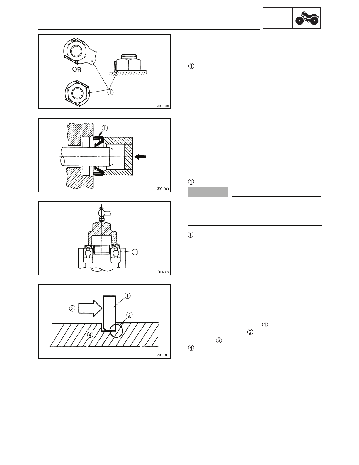
EBS00016
LOCK WASHERS/PLATES AND COTTER
PINS
After removal, replace all lock washers/plates
and cotter pins. After the bolt or nut has
been tightened to specification, bend the lock
tabs along a flat of the bolt or nut.
EBS00017
BEARINGS AND OIL SEALS
Install bearings and oil seals so that the manufacturer’s marks or numbers are visible. When
installing oil seals, lubricate the oil seal lips
with a light coat of lithium-soap-based grease.
Oil bearings liberally when installing, if appropriate.
Oil seal
GEN
INFO
NOTICE
Do not spin the bearing with compressed
air because this will damage the bearing
surfaces.
Bearing
EBS00018
CIRCLIPS
Before reassembly, check all circlips carefully
and replace damaged or distorted circlips.
Always replace piston pin clips after one use.
When installing a circlip , make sure the
sharp-edged corner is positioned opposite
the thrust that the circlip receives.
Shaft
1 - 3
Page 19
IMPORTANT INFORMATION
1
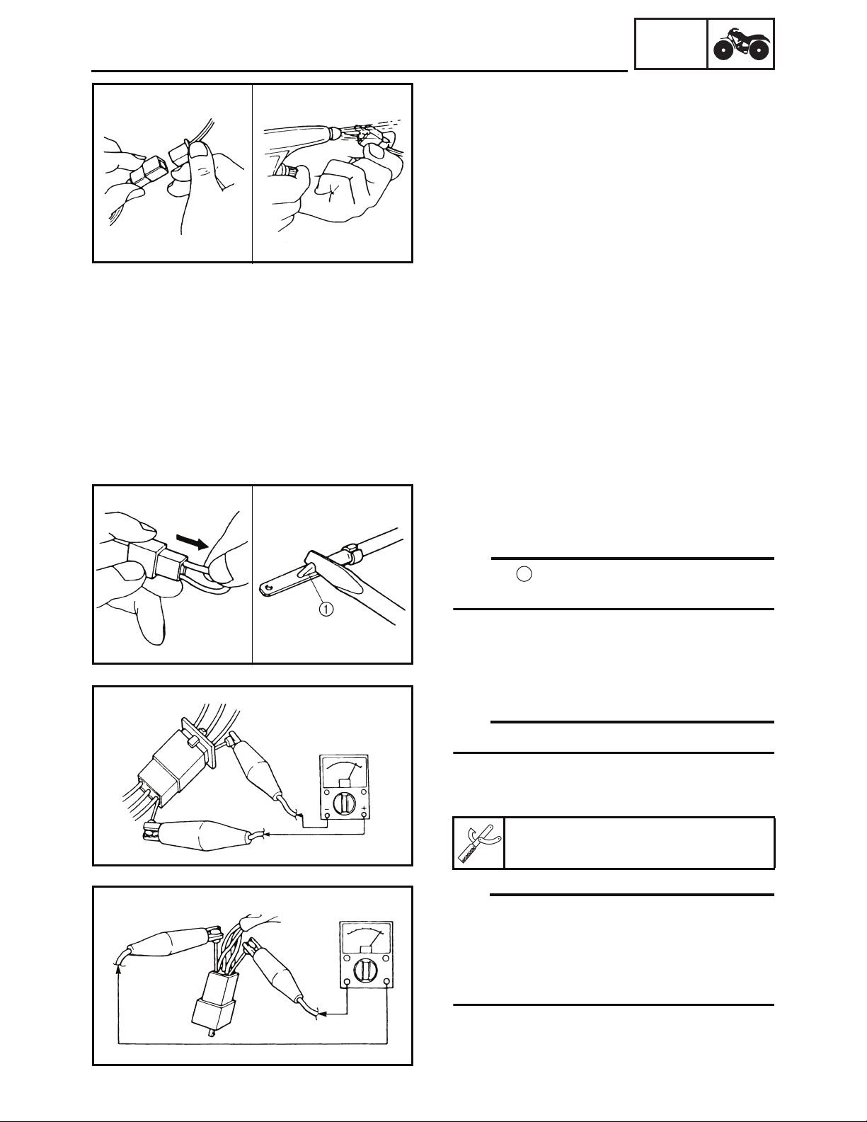
EBS00019
CHECKING THE CONNECTIONS
Check the leads, couplers, and connectors for
stains, rust, moisture, etc.
1. Disconnect:
• lead
• coupler
• connector
2. Check:
• lead
• coupler
• connector
Moisture → Dry with an air blower.
Rust/stains → Connect and disconnect several times.
GEN
INFO
3. Check:
• all connections
Loose connection → Connect properly.
TIP
_
If the pin on the terminal is flattened, bend it
up.
4. Connect:
• lead
• coupler
• connector
TIP
_
Make sure all connections are tight.
5. Check:
• continuity (with the pocket tester)
Pocket tester
P/N. YU-03112-C, 90890-03112
TIP
_
• If there is no continuity, clean the terminals.
• When checking the wire harness, perform
steps (1) to (3).
• As a quick remedy, use a contact revitalizer
available at most part stores.
1 - 4
Page 20
GEN
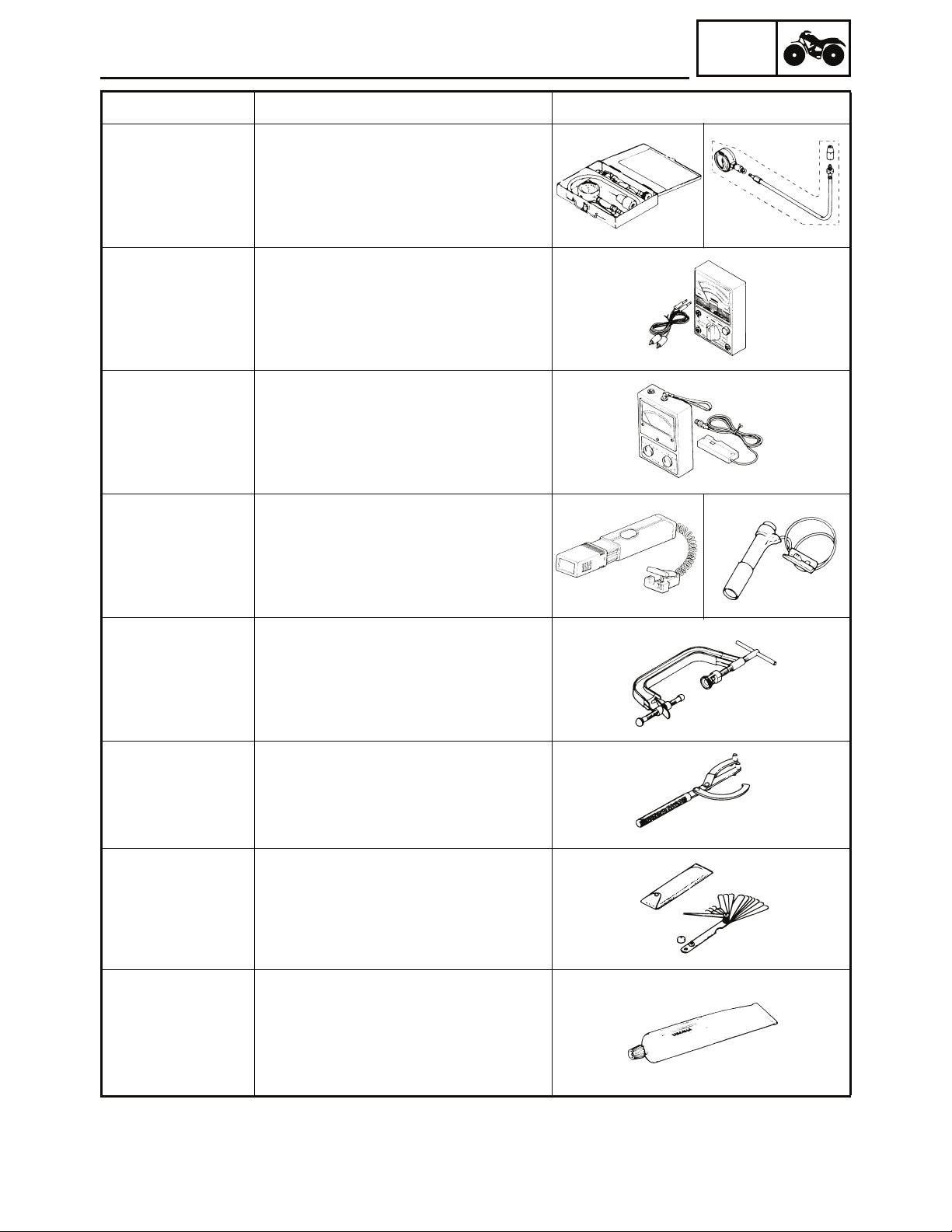
SPECIAL TOOLS
EBS00021
SPECIAL TOOLS
The following special tools are necessary for complete and accurate tune-up and assembly. Use
only the appropriate special tools; this will help prevent damage caused by the use of inappropriate
tools or improvised techniques. Special tools may differ by shape and part number from country to
country. In such a case, two types are provided.
When placing an order, refer to the list provided below to avoid any mistakes.
For US and CDN
P/N. YM-, YU-, YS-, YK-, ACC-
Except for US and CDN
P/N. 90890-
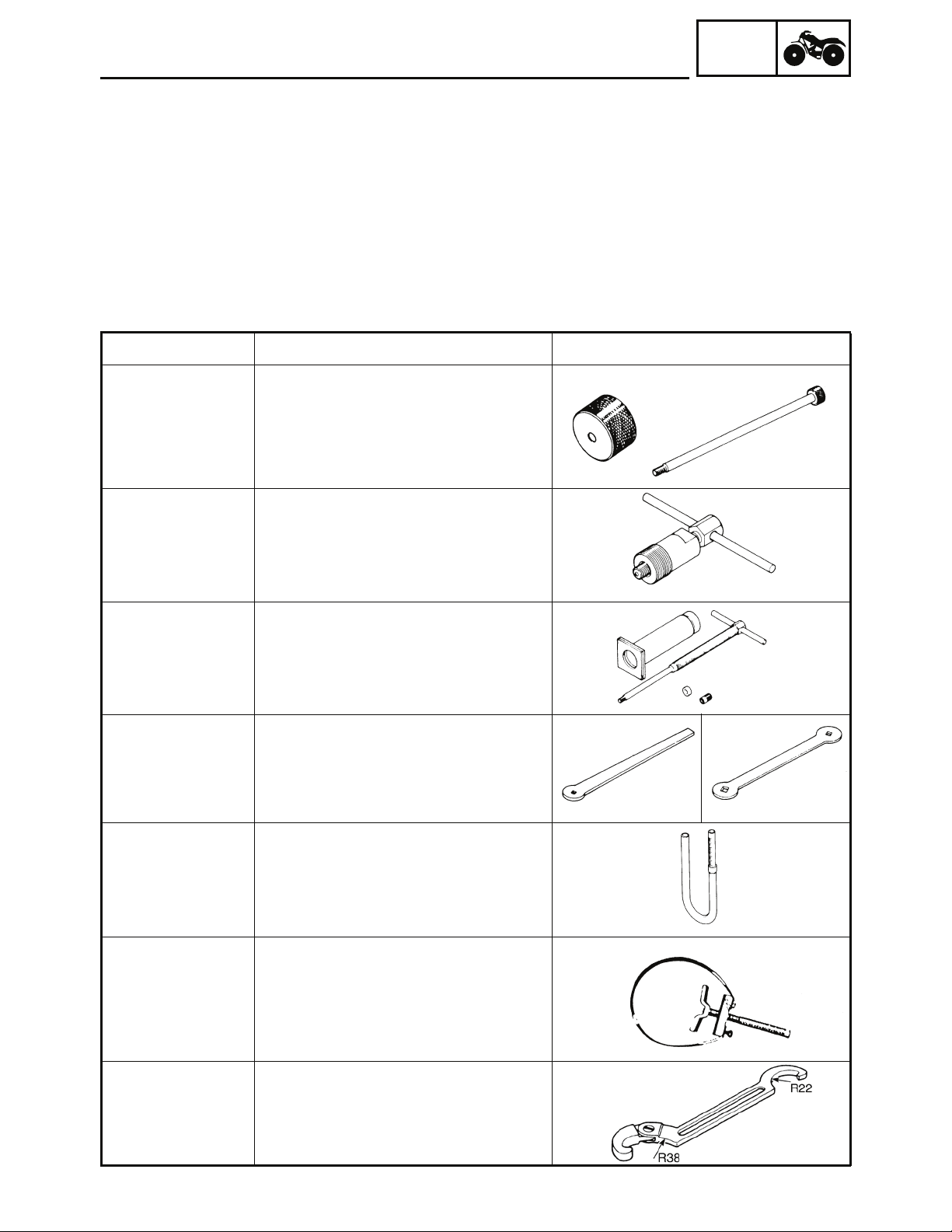
Tool No. Tool name/Function Illustration
Bolt
90890-04158
YM-04158
Weight
90890-01084
Set
YU-01083-A
Slide hammer bolt (M5)/weight/set
These tools are used to remove the rocker
arm shaft.
INFO
90890-01189
YM-01189
90890-01304
YU-01304
90890-01311
YM-08035
90890-01312
YM-01312-A
Flywheel puller
This tool is needed to remove the rotor.
Piston pin puller set
This tool is used to remove the piston pin.
Tappet adjusting tool (3 mm)
This tool is necessary for adjusting the
valve clearance.
Fuel level gauge
This gauge is used to measure the fuel
level in the float chamber.
Sheave holder
90890-01701
YS-01880-A
90890-01268
YU-01268
This tool is needed to hold the rotor when
removing or installing the rotor nut.
Ring nut wrench
Spanner wrench
This tool is used to adjusting the front and
rear shock absorbers.
1 - 5
Page 21
GEN
SPECIAL TOOLS
Tool No. Tool name/Function Illustration
INFO
Gauge
90890-03081
YU-33223
Adapter
90890-04082
90890-03112
YU-03112-C
90890-03113
YU-8036-B
90890-03141
YM-33277-A
Compression gauge
Adapter
These tools are needed to measure
engine compression.
Pocket tester
This instrument is needed for checking the
electrical system.
Engine tachometer
This tool is needed for observing engine
rpm.
Timing light
This tool is necessary for checking ignition
timing.
Compressor
90890-04019
YM-04019
Attachment
90890-04108
YM-04108
90890-01235
YU-01235
90890-03079
YM-34483
Bond
90890-85505
Sealant
ACC-11001-05-01
Valve spring compressor
Valve spring compressor attachment
This tool is needed to remove and install
the valve assemblies.
Rotor holding tool
This tool is used to remove the flywheel
magneto.
Thickness gauge
This tool is used to measure the valve
cleanance.
Yamaha bond No. 1215
Sealant (Quick Gasket
This sealant (bond) is used on crankcase
mating surfaces, etc.
®
)
1 - 6
Page 22
SPECIAL TOOLS
INFO
Tool No. Tool name/Function Illustration
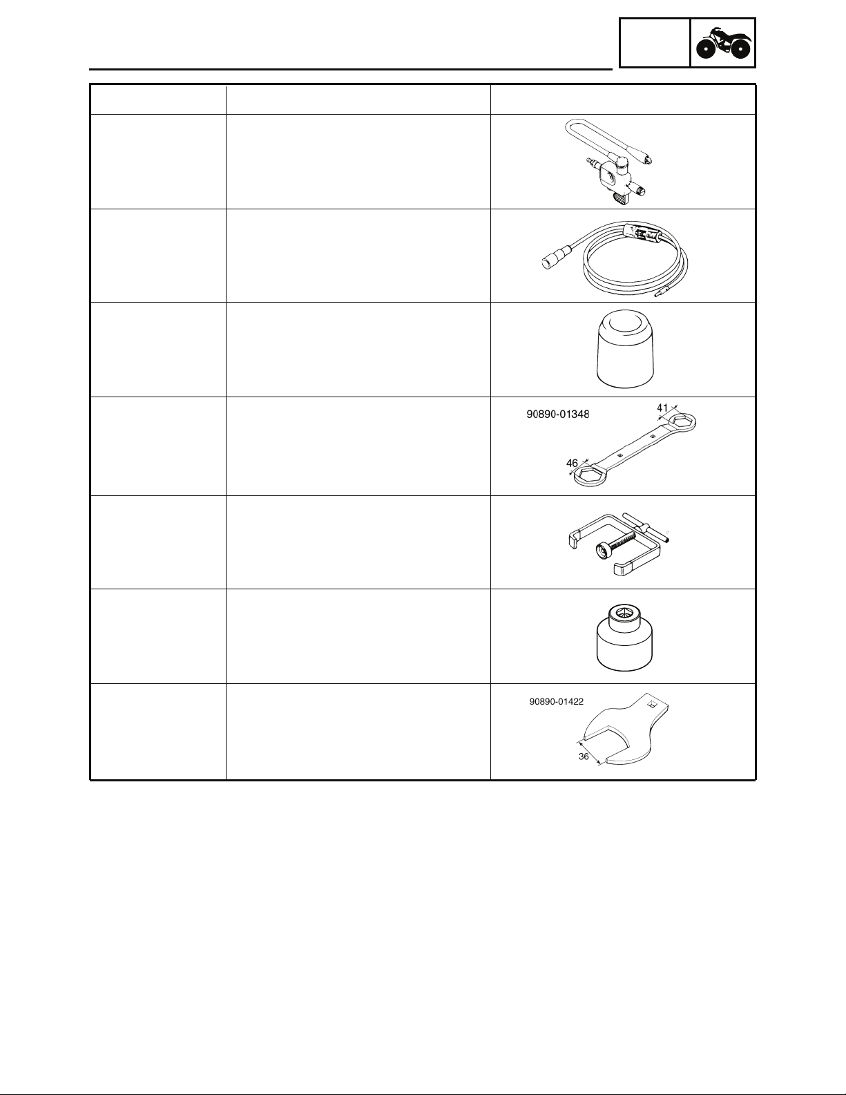
Ignition checker
90890-06754
This instrument is necessary for checking
the ignition system components.
Dynamic spark tester
YM-34487
This instrument is necessary for checking
the ignition system components.
Oil seal guide
90890-01384
YM-33299
90890-01348
YM-01348
This tool is used for protecting the oil seal
lip when installing the secondary sliding
sheave.
Lock nut wrench
This tool is used for removing the
A.C. magneto rotor.
GEN
90890-01337
YM-33285
YM-33285-6
90890-01493
YM-01493
90890-01422
YM-37132
Clutch spring holder
These tool are used for removing the nut
with holding the compression spring.
Socket wrench 39 mm
This tool is used when removing or installing the secondary sheave nut.
Axle nut wrench (36mm)
This tool is neededto loosen or tighten the
rear axle nut.
1 - 7
Page 23
GENERAL SPECIFICATIONS
EBS01001
SPECIFICATIONS
GENERAL SPECIFICATIONS
Item Standard
SPEC
Model code
43D7
Dimensions
Overall length 1,490 mm (58.7 in)
Overall width 885 mm (34.8 in)
Overall height 910 mm (35.8 in)
Seat height 654 mm (25.7 in)
Wheelbase 1,010 mm (39.8 in)
Minimum ground clearance 100 mm (3.9 in)
Minimum turning radius 2,900 mm (114in)
Basic weight
With oil and full fuel tank 120 kg (264 lb)
Engine
Engine type Air cooled 4-stroke, SOHC
Cylinder arrangement Single cylinder
Displacement 88.0 cm (5.37 cu.in)
×
Bore
47.0 × 51.0 mm (1.85 × 2.01 in)stroke
3
Compression ratio 10.2 : 1
Standard compression pressure (at sea level) 1,250 kPa
(12.5 kg/cm
2
, 177.8 psi) at 1,000 r/min
Electric starter & kickstarterStarting system
2
Lubrication system
Wet sump
Oil type or grade
Engine oil
0˚
10˚ 30˚
50˚
70˚
90˚
110˚
130˚F
YAMALUBE 4, SAE5W-30 or SAE10W-40
or SAE20W-50
YAMALUBE 4 (20W-50) or SAE 20W-50
YAMALUBE 4 (10W-40) or SAE 10W-40
SAE 5W-30
-20˚
-10˚ 0˚
10˚
30˚ 40˚ 50˚C
20˚
Final transmission oil SAE 80API “GL-4” Hypoid gear oil
Oil capacity
Engine oil
Periodic oil change 0.75 L (0.66 Imp qt, 0.80 US qt)
Total amount 0.80 L (0.70 Imp qt, 0.85 US qt)
Final transmission oil
Total amount 0.30 L (0.27 Imp qt, 0.32 US qt)
Air filter
Wet type element
2 - 1
Page 24

GENERAL SPECIFICATIONS
Item Standard
Fuel
Type Unleaded gasoline only
Fuel tank capacity 4.8 L (1.06 lmp gal, 1.27 US gal)
Fuel reserve amount 1.0 L (0.22 Imp gal, 0.26 US gal)
Carburetor
Type/quantity SVR 22-1G x 1
Manufacturer TK
Spark plug
Type/manufacturer NGK/CR7HSA
Spark plug gap 0.6 ~ 0.7 mm (0.024 ~ 0.028 in)
Clutch type Dry, centrifugal automatic
Transmission
Primary reduction system V-belt
Primary reduction ratio 2.47-0.61:1
Secondary reduction system Spur
Secondary reduction ratio 41/15 × 45/13 (9.462)
Third reduction system Chain drive
Third reduction ratio 28/13(2.154)
Transmission type V-belt automatic
Chassis
Frame type Steel tube frame
Caster angle 4°00’
Camber angle –0°30’
Kingpin angle 18°00’
Trail 16 mm (0.63 in)
Tread (STD) front 710 mm (27.95 in)
rear 655 mm (25.79 in)
Toe-in (with tires touching the ground) 15 mm (0.59 in)
Tire
Type Tubeless
Size front AT18 × 7-8
rear AT18 × 9-8
Manufacturer front MAXXIS
rear MAXXIS
Type front M939
rear M940
Tire pressure (cold tire)
Maximum load* 70.0 kg (154 lb)
Off-road riding front 22 ~ 25 kPa (0.22 ~ 0.25 kgf/cm, 3.2 ~ 3.6 psi)
rear 22 ~ 25 kPa (0.22 ~ 0.25 kgf/cm, 3.2 ~ 3.6 psi)
*Load in total weight of rider and
accessories
SPEC
2
2
2 - 2
Page 25

GENERAL SPECIFICATIONS
Item Standard
Brake
Front brake type Drum brake
operation Right hand operation
Rear brake type Single disc brake
operation Left hand operation
Suspension
Front suspension Double wishbone / Independent
Rear suspension Swingarm
Shock absorber
Front shock absorber Coil spring/oil damper
Rear shock absorber Coil spring/oil damper
Wheel travel
Front wheel travel 111 mm (4.4 in)
Rear wheel travel 83 mm (3.3 in)
Electrical
Ignition system AC-CDI
Generator system AC magneto
Battery type GTX5L-BS
Battery capacity 12 V 4.0 Ah
SPEC
2 - 3
Page 26
ENGINE SPECIFICATIONS
EBS01002
SPEC
ENGINE SPECIFICATIONS
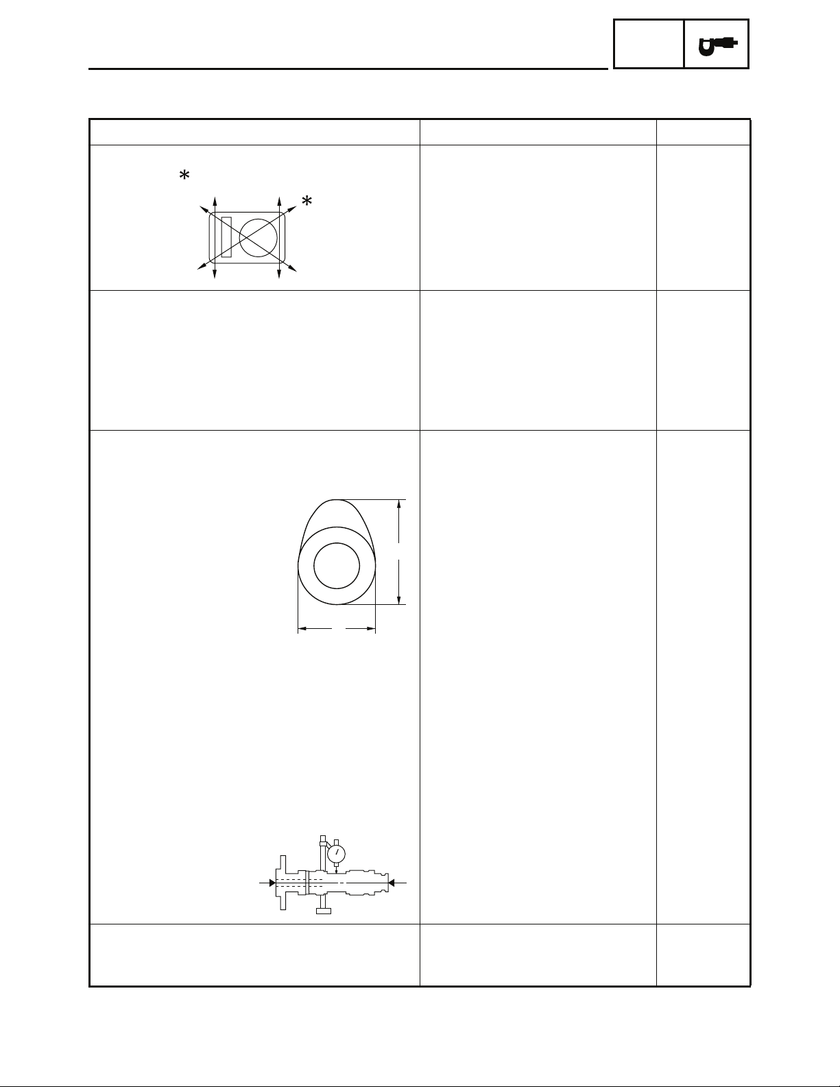
Item Standard Limit
Cylinder head
Warp limit 0.05 mm
Cylinder
Bore size 47.000 ~ 47.010 mm
Taper limit ---- 0.05 mm
Maximum out-of-round ---- 0.01 mm
Camshaft
Drive method Chain drive (Left) ---Cam dimensions
7.00 ~ 7.40 cm
(0.43 ~ 0.45 cu.in)
(1.8504 ~ 1.8508 in)
3
(0.002 in)
47.10 mm
(1.8543 in)
(0.002 in)
(0.0004 in)
A
B
Intake “A” 25.683 ~ 25.843 mm
(1.0111 ~ 1.0174 in)
“B” 20.985 ~ 21.015 mm
(0.8262 ~ 0.8274 in)
Exhaust “A” 25.525 ~ 25.685 mm
(1.0049 ~ 1.0112 in)
“B” 20.985 ~ 21.015 mm
(0.8262 ~ 0.8274 in)
Camshaft runout limit ---- 0.03 mm
Timing chain
Timing chain type/No. of links KMC 92 RH 2005 / 86 ---Timing chain adjustment method Automatic ----
25.583 mm
(1.0072 in)
20.886 mm
(0.8223 in)
25.425 mm
(1.0010 in)
20.886 mm
(0.8223 in)
(0.0012 in)
2 - 4
Page 27
ENGINE SPECIFICATIONS
Item Standard Limit
Rocker arm/rocker arm shaft
Rocker arm inside diameter 10.000 ~ 10.015 mm
(0.3937 ~ 0.3943 in)
Rocker arm shaft outside diameter 9.972 ~ 9.987 mm
(0.3926 ~ 0.3932 in)
Rocker-arm-to-rocker-arm-shaft clearance 0.013 ~ 0.043 mm
(0.0005 ~ 0.0017 in)
Valve, valve seat, valve guide
Valve clearance (cold) IN 0.07 ~ 0.10 mm
(0.0027 ~ 0.0039 in)
EX 0.07 ~ 0.10 mm
(0.0027 ~ 0.0039 in)
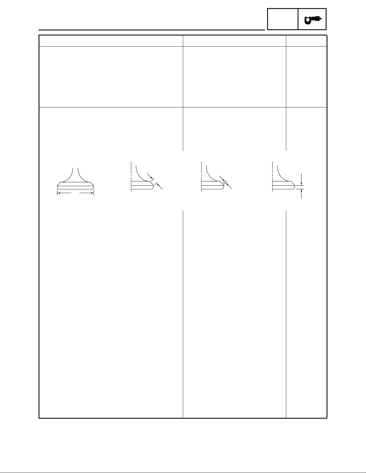
Valve dimensions
SPEC
10.100 mm
(0.3976 in)
9.910 mm
(0.3902 in)
----
----
----
B
A
Head Diameter Face Width Seat Width Margin Thickness
“A” head diameter ----
“B” face width ----
“C” seat width
“D” margin thickness
Stem outside diameter
Guide inside diameter
IN 20.9 ~ 21.1 mm
(0.8228~ 0.8307 in)
EX 18.9 ~ 19.1 mm
(0.7441~ 0.7520 in)
IN 1.50 ~ 1.80 mm
(0.0591~ 0.07.9 in)
EX 1.50 ~ 1.80 mm
(0.0591~ 0.0709 in)
IN 0.8 ~ 1.1 mm
(0.0315 ~ 0.0433 in)
EX 0.8 ~ 1.1 mm
(0.0315 ~ 0.0433 in)
IN 0.5 ~ 0.9 mm
(0.0197 ~ 0.0354 in)
EX 0.6 ~ 1.0 mm
(0.0236 ~ 0.0394 in)
IN 4.975 ~ 4.990 mm
(0.1959 ~ 0.1965 in)
EX 4.955 ~ 4.970 mm
(0.1951~ 0.1957 in)
IN 5.000 ~ 5.012 mm
(0.1969 ~ 0.1973 in)
EX 5.000 ~ 5.012 mm
(0.1969 ~ 0.1973 in)
C
1.6 mm
(0.0630 in)
1.6 mm
(0.0630 in)
4.900 mm
(0.1930 in)
4.900 mm
(0.1930 in)
5.030 mm
(0.1980 in)
5.030 mm
(0.1980 in)
D
----
----
----
----
2 - 5
Page 28
ENGINE SPECIFICATIONS
Item Standard Limit
SPEC
Stem-to-guide clearance IN 0.010 ~ 0.037 mm
(0.0004 ~ 0.0015 in)
EX 0.025 ~ 0.052 mm
(0.0010 ~ 0.0020 in)
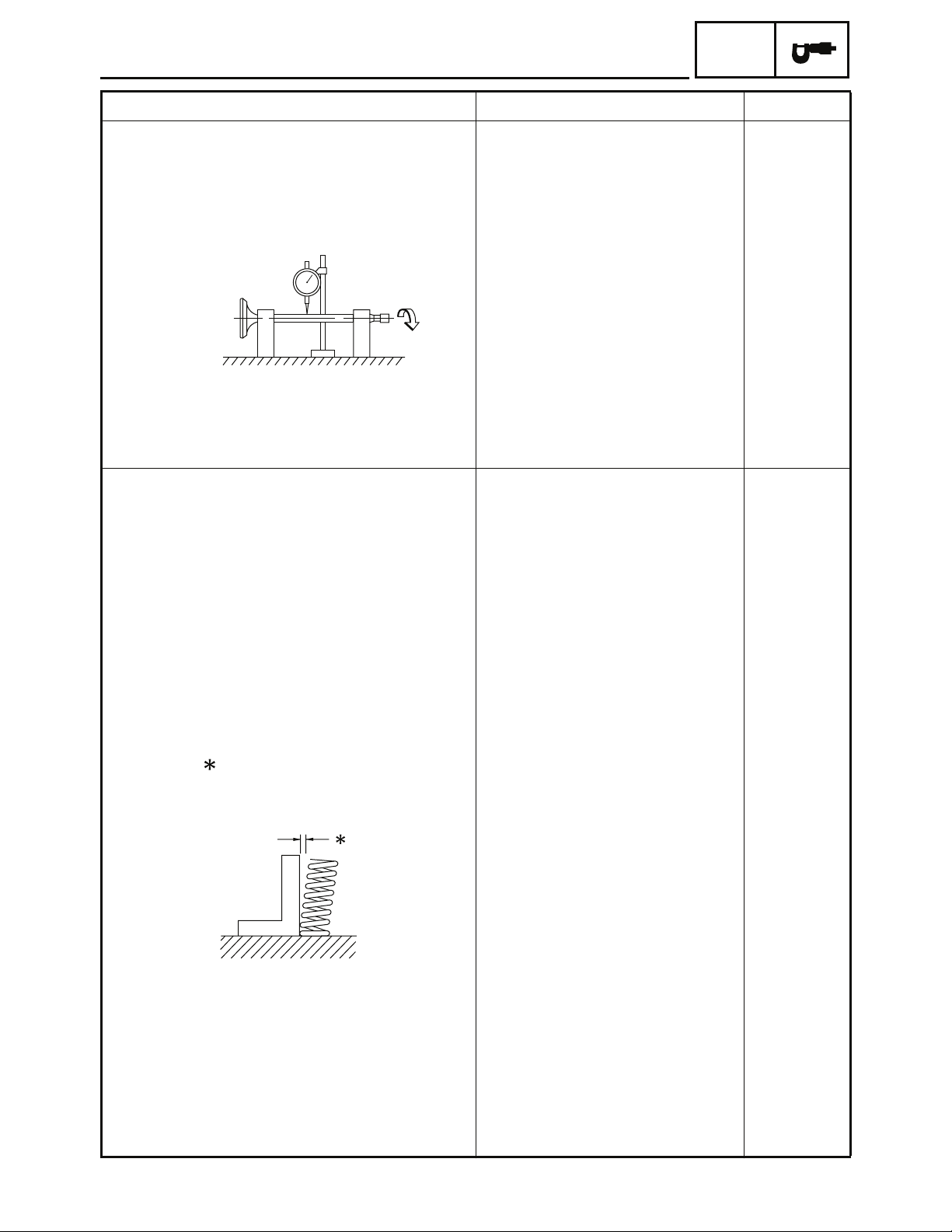
Stem runout limit ---- 0.02 mm
Valve seat width IN 0.8 ~ 1.1 mm
(0.0315 ~ 0.0433 in)
EX 0.8 ~ 1.1 mm
(0.0315 ~ 0.0433 in)
Valve spring
Inner spring
Free length IN 30.00 mm (1.18 in) 27.00 mm
EX 30.00 mm (1.18 in) 27.00 mm
Compressed pressure
(installed) IN 39.14 ~ 47.77 N at 22.45 mm
(3.99 ~ 4.87 kg,
8.80 ~ 10.74 lb at 0.898 in)
EX 39.14 ~ 47.77 N at 22.45 mm
(3.99 ~ 4.87 kg,
8.80 ~ 10.74 lb at 0.898 in)
Tilt limit IN
EX
0.08 mm
(0.0031 in)
0.10 mm
(0.0039 in)
(0.0008 in)
1.6 mm
(0.0630 in)
1.6 mm
(0.0630 in)
(1.06 in)
(1.06 in)
°/1.1 mm
2.0
(2.0°/0.04 in)
°/1.1 mm
2.0
(2.0°/0.04 in)
----
----
Direction of winding
(top view) IN Counterclockwise ----
EX Counterclockwise ----
Outer spring
Free length
IN 33.50 mm (1.32 in) 30.50 mm
(1.20 in)
EX 33.50 mm (1.32in) 30.50 mm
(1.20 in)
2 - 6
Page 29
ENGINE SPECIFICATIONS
SPEC
LimitStandardItem
Compressed pressure
installed)
Tilt limit
Direction of winding
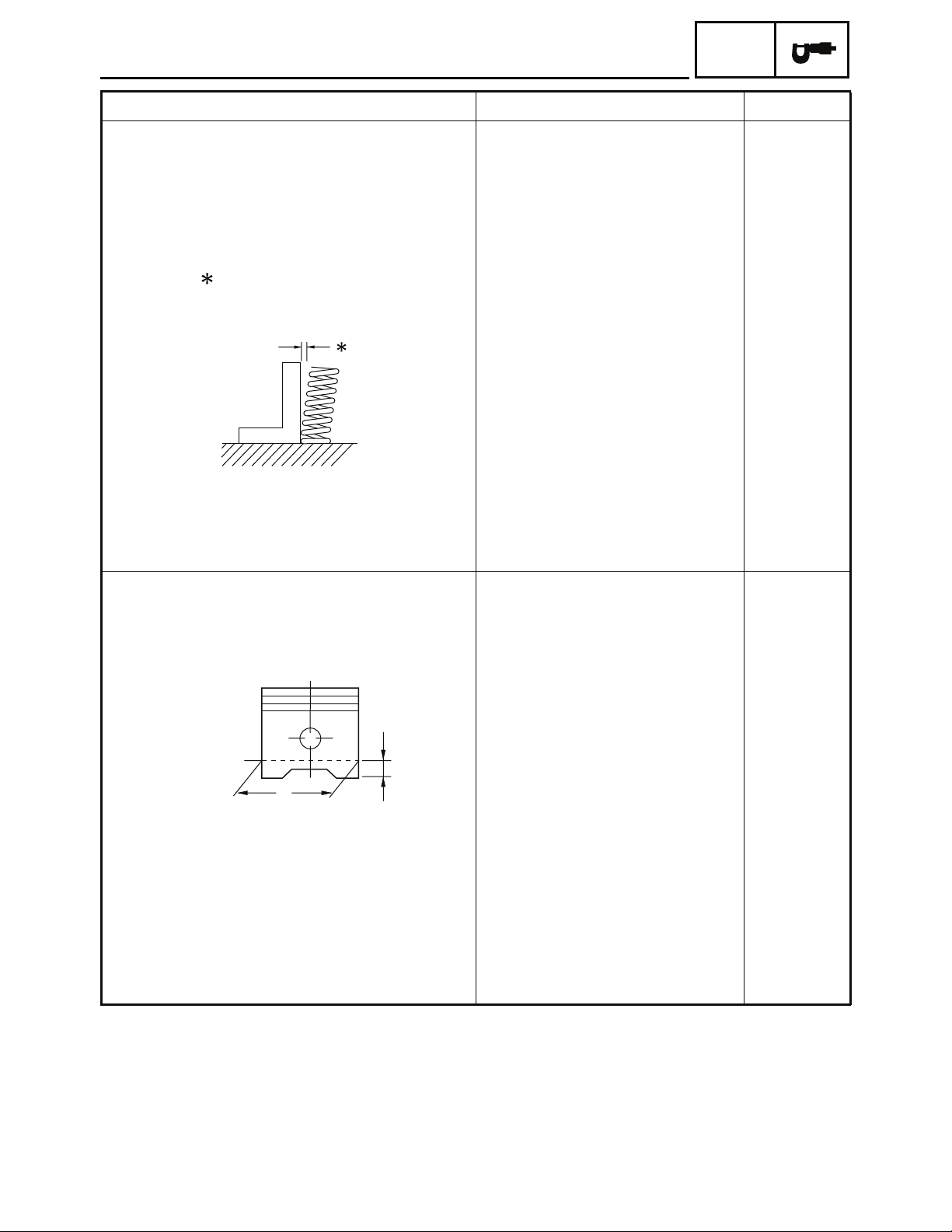
Piston
Piston to cylinder clearance 0.010 ~ 0.040 mm
Piston size “D”
IN
EX
IN
EX
IN(top view)
73.87 ~ 90.06 N at 25.45 mm
7.52 ~ 9.18 kg,
16.59 ~ 20.24 lb at 1.00 in)
73.87 ~ 90.06 N at 25.45 mm
7.52 ~ 9.18 kg,
16.59 ~ 20.24 lb at 1.00 in)
Counterclockwise
46.970 ~ 46.990 mm
(1.8492 ~ 1.8500 in)
----
----
2.0
°/1.2 mm
(
2.0
°/0.05 in)
2.0°/1.2 mm
(
2.0
°/0.05 in)
----Counterclockwise
----EX
0.10 mm
(0.0039 in)(0.0004 ~ 0.0016 in)
H
D
Measuring point “H”
Piston off-set
Piston pin bore inside diameter 13.002 ~ 13.008 mm
Piston pin outside diameter 12.996 ~ 13.000 mm
5.0 mm (0.20 in)
(0.5119 ~ 0.5121 in)
(0.5117 ~ 0.5118 in)
2 - 7
----0.5 mm (0.02 in)
----Intake sidePiston off-set direction
13.040 mm
(0.5134 in)
12.960 mm
(0.5102 in)
Page 30
Piston rings
Top ring
ENGINE SPECIFICATIONS
SPEC
LimitStandardItem
Type
Dimensions (B × T)
End gap (installed)
Side clearance (installed)
2nd ring
Type
Dimensions (B × T)
End gap (installed)
Side clearance
Oil ring
Dimensions (B × T)
End gap (installed)
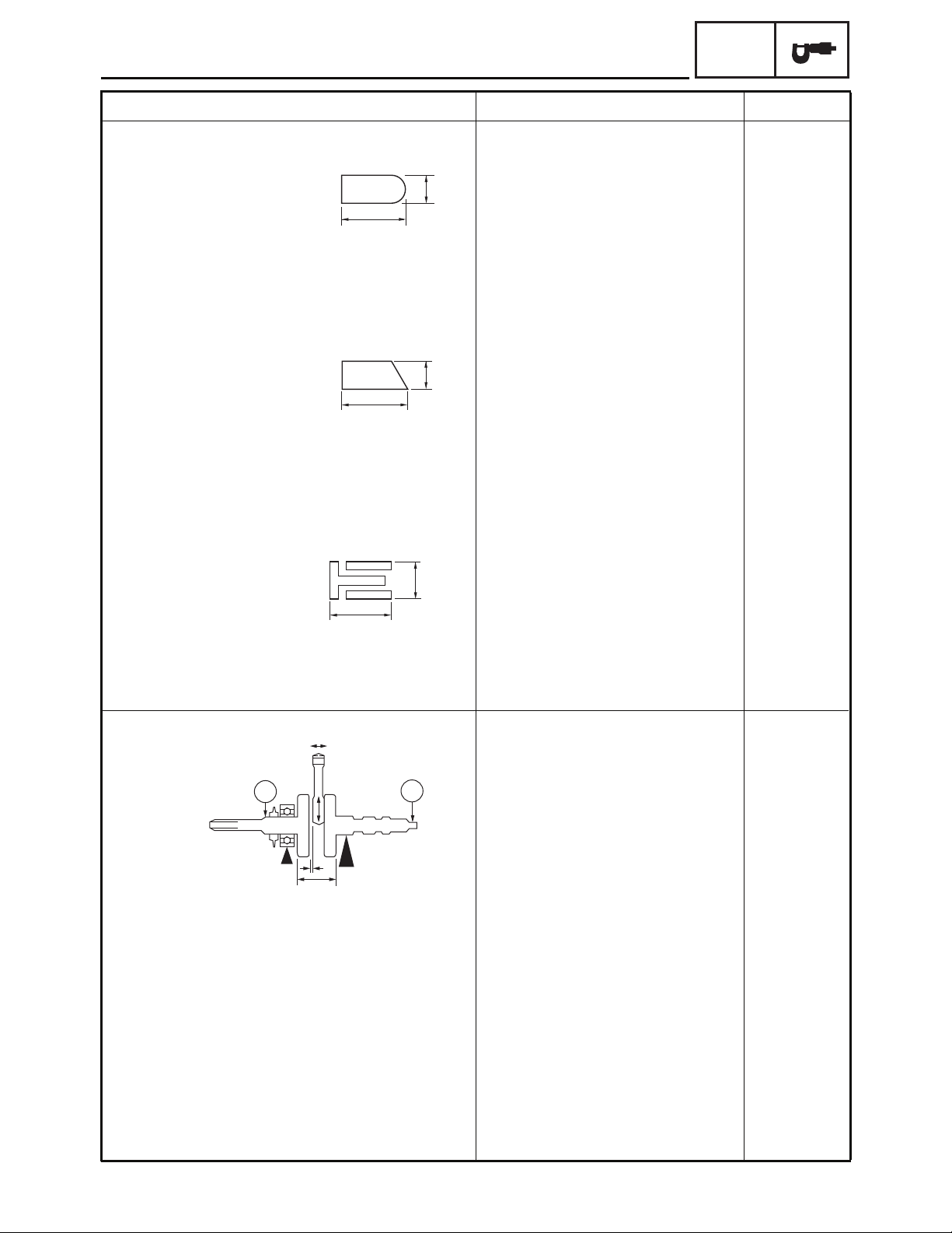
Crankshaft
B
T
Barrel
1.0 × 2.1 mm
----
----
(0.0394 × 0.0827 in)
0.10 ~ 0.25 mm
(0.0039~0.0098in)
0.015 ~0.055 mm
(0.0006~0.0022in)
B
T
0.45 mm
(0.0177in)
0.09 mm
(0.0035in)
----Taper
1.0 × 2.0 mm
----
0.0394 × 0.0787 in)
0.25 ~ 0.40 mm
(0.0098~0.0157in)
0.015 ~ 0.055 mm
(0.0006~0.0022in)
B
T
2.0 × 1.9 mm
0.55mm
(0.0217in)
0.09mm
(0.0035in)
----
(0.0787 × 0.0748 in)
0.20 ~ 0.70 mm
----
(0.0079~0.0276in)
F
C1
E
D
Crankwidth 44.10~44.15mm
A
”
“
A
C2
(1.7362~1.7382in)
Big end side clearance “D” 0.10~0.30mm
(0.0039~0.0118in)
Big end radial clearance “E” 0.007~0.015mm
(0.0003~0.0006in)
Small end free play “F” 0.80~1.00mm
(0.0315~0.0394in)
2 - 8
----
0.04 mm----Runout limit C1
(0.0016in)
0.04 mm----C2
(0.0016in)
0.50 mm
(0.0197in)
----
1.50mm
(0.0591in)
Page 31

ENGINE SPECIFICATIONS
Clutch
Automatic centrifugalClutch type
4.0 mmClutch shoe thickness
(0.1575 in)
Clutch shoe spring free length
Clutch housing inside diameter
Compression spring free length
Weight outside diameter
Clutch-in revolution
Clutch-stall revolution
V-belt
V-belt width
Transmission
Transmission type
Primary reduction system
Primary reduction ratio
Secondary reduction system Spur gear
Secondary reduction ratio 41/15 × 45/13(9.462)
Max. main axle runout
Max. drive axle runout
Carburetors
Main jet
(A.J)
(P.J)
(V.S)
(F.L)
30.5 mm
107.0 ~107.2 mm
(4.21 ~4.22 in)
87.9 mm (3.46 in)
14.9 ~ 15.1 mm
(0.587 ~0.594 in)
2110±140r/min
2350±150 r/min
18.0 mm (0.709 in)
V-belt automatic
2.47~0.61:1
1.6Valve seat size
5.0 ~ 6.0 mm (0.20 ~ 0.24 in)Fuel level
Above the float chamber mating
Surface
SPEC
LimitStandardItem
----
0 mm.2
(0.078 in)
----
107.5 mm
(4.23in)
----
17.0 mm
(0.669in)
0.08 mm
(0.0031in)
0.08 mm
(0.0031in)
----43D100I. D. mark
----#100(M.J)
----1.0Air jet
----#4T12 1/1(J.N)Jet needle
----2.090 H5.5(N.J)Needle jet
----#32Pilot jet
----
----
----
----1,600 ~ 1,800 r/minEngine idle speed
2 - 9
Page 32

ENGINE SPECIFICATIONS
Oil pump
Inner-rotor-to-outer-rotor-tip clearance
Outer-rotor-to-oil-pump-housing clearance
Oil-pump-housing-to-inner-rotor-and-outerrotor clearance
Lubrication chart
: Pressure feed
: Splashed scavenge
0.04 ~ 0.12mm
(0.0016 ~ 0.0047 in)
0.14 ~ 0.21 mm
(0.0055 ~ 0.0083 in)
0.06 ~ 0.11 mm
(0.0024 ~ 0.0043 in)
SPEC
LimitStandardItem
----TrochoidOil pump type
0.15 mm
(0.006 in)
0.28 mm
(0.0110 in)
0.20 mm
(0.0079 in)
Piston
Crankshaft
pin
Piston pin
Oil pump
Oil strainer
Camshaft
Rocker arm
Timing
chain area
Valve
2 - 10
Page 33

CHASSIS SPECIFICATIONS
EBS01003
SPEC
CHASSIS SPECIFICATIONS
Item Standard Limit
Front suspension
Shock absorber travel 35 mm (1.38 in) ---Optional spring No ----
Rear suspension
Shock absorber travel 40 mm (1.57 in) ---Optional spring No ----
Front wheel
Type Panel wheel ---Rim size 8 × 5.5 AT ---Rim material Steel ---Rim runout limit radial ---- 2.0 mm
(0.08 in)
lateral ---- 2.0 mm
(0.08 in)
Rear wheel
Type Panel wheel ---Rim size 8 × 7 AT ---Rim material Steel ---Rim runout limit radial ---- 2.0 mm
(0.08 in)
lateral ---- 2.0 mm
(0.08 in)
Drive chain
Type/ manufacturer #520/ KMC
Link quantity 66
Drive chain slack 10~25 mm (0.39~0.98 in)
Front drum brake
Type
Brake drum inside diameter
Lining thickness
Shoe springfree length
Leading, trailing
95.0 mm (3.74 in)
3.5 mm (0.14 in)
57.5 mm (2.26 in)
----
96.0 mm
(3.78 in)
2.0 mm
(0.08 in)
----
2 - 11
Page 34

CHASSIS SPECIFICATIONS
Item Standard Limit
Rear disc brake
Type
Disc outside diameter × thickness 3.0 mm
Brake disk maximum deflection 0.15 mm
Pad thickness inner 3.7 mm (0.15 in)
Pad thickness outer 3.7 mm (0.15 in) 1.0 mm
Master cylinder inside diameter
Caliper cylinder inside diameter
Brake fluid type
Brake lever
Brake lever free play (pivot) front 4.0 ~ 6.0 mm (0.16 ~ 0.24 in) ----
rear 0 ~ 1.5 mm (0 ~ 0.06 in)
Throttle lever free play 1.0 ~ 3.0 mm (0.04 ~ 0.12 in) ----
Single
190.0 × 3.5 mm (7.48 × 0.14 in)
12.7 mm (0.50 in)
30.23 mm (1.19 in)
DOT 4
SPEC
(0.12 in)
(0.006 in)
1.0 mm
(0.04 in)
(0.04 in)
----
----
----
----
----
Parking brake cable end length
53.0 ~ 57.0 mm (2.09 ~ 2.24 in)
----
2 - 12
Page 35

ELECTRICAL SPECIFICATIONS
EBS01004
SPEC
ELECTRICAL SPECIFICATIONS
Item Standard Limit
Voltage
Ignition system
Ignition timing (B.T.D.C.) 13.0 °/1,700 r/min ---Advanced timing (B.T.D.C.) 29°/4,000 r/min ---Advancer type Electrical (digital) ----
C.D.I.
Magneto model/manufacturer C1120-A26-6000/SHIHLIN ---Pickup coil resistance/color 94 ~ 140 at 20 °C (68 °F)/
Source coil resistance/color 640 ~ 960 at 20 °C (68 °F)/
C.D.I. unit model/manufacturer C0410-A26-6000/SHIHLIN ----
Ignition coil
Model/manufacturer C0510-A26-6000/SHIHLIN ---Minimum spark gap 6 mm (0.24 in) ---Primary winding resistance 0.19 ~ 0.23 at 20 °C (68 °F)
Secondary winding resistance
Spark plug cap
Type Resin ---Resistance 5 k
Charging system
Type A.C. magneto ---Model/manufacturer C1120-A26-6000/SHIHLIN ---Nominal output 14 V 85 W at 5,000 r/min ---Charging coil resistance/color 0.60 ~ 0.90 at 20 °C (68 °F)/
Rectifier/regulator
Regulator type Semi conductor-short circuit ---No-load regulated voltage (DC) 14.0 ~ 15.0 V ----
Model/manufacturer C1600-9KB0-0000/EYE
Capacity (DC) 10 A
Withstand voltage 500 V
12 V ----
Ω
White/Blue—White/Red
Ω
Black/Green—Black/Red
Ω
2.79 ~ 3.41 k at 20 °C (68 °F)
Ω
White—White
Ω
Ω
----
----
----
----
----
----
----
----
----
2 - 13
Page 36

ELECTRICAL SPECIFICATIONS
Item Standard Limit
Electric starter system
Starter motor
0.35 kWOutput
Armature coil resistance 0.014 ~ 0.019 at 20 °C (68 °
Brush overall length
Spring force
Starter relay
Coil winding resistance 2.98 ~ 4.03 at 20 °C (68 °F)
Circuit breakers
Type
Amperage for individual circuit
Main fuse ----
1.0 ~ 3.0 N
(102~ 306gf, 3.60 ~ 10.80 oz)
Fuse
10A × 1
Ω
Ω
SPEC
F)
----Constant meshType
----C1200-A26-6000/SYModel/manufacturer
----
----
3.5 mm7.0 mm (0.28 in)
(0.14 in)
----
19.5 mm22.0 mm (0.87 in)Commutator diameter
(0.77in)
----.6 mm ( 0.06 in)1Mica undercut
----C5850-FBF0-0000/SYModel/manufacturer
----150 AModel/manufacturer
----
----
2 - 14
Page 37

EBS01005
TIGHTENING TORQUES
ENGINE TIGHTENING TORQUES
TIGHTENING TORQUES
SPEC
Part to be tightened Part name
Cover head cylinder M6 4 12 1.2 8.7
Spark plug —
Cylinder head (Carb. joint) Stud bolt
Cylinder head (exhaust pipe) Stud bolt M6 2 9 0.9 6.5
Valve adjuster
Cylinder head(timing chain side)
Timing chain tensioner(body)
Timing chain tensioner(plug) Bolt
Duct inlet and cover crankcase 2
Duct inlet and air shroud 1 and 2
Air shroud 1 crankcase 1
Air shroud 1 and 2
Air shroud 2 and Cover 1
Cylinder
Cylinder stud bolt 1
Cylinder stud bolt 2
Cover crankcase 1
Sheave primary fixed
Clutch housing Nut
Starter motor
Fan
C.D.I. magneto rotor Nut M12 1 55 5.5 40
Stator assy
Pulse
Crankcase cover 2
Oil pump driven gear
Drive sprocket
Cover plate
Primary drive gear shaft bearing
retainer
Engine oil drain bolt Bolt M30
Crankcase 1 and 2
Air filter holder
Timing chain guide
Air filter
Carburetor overflow drain plug
Carburetor joint
Exhaust pipe
Muffler
Spark arrester tailpipe Screw M5 1 5 0.5 3.6
Bolt
Bolt
Bolt
Bolt
Screw
Bolt
Bolt
Screw
Bolt M6 1 12 1.2 8.7
Stud bolt
Stud bolt
Bolt M6 8 12 1.2 8.7
Nut
Bolt M6 2 12 1.2 8.7
Bolt
Bolt M6 2 12 1.2 8.7
Bolt
Bolt
Nut
Bolt
Bolt
Bolt
Bolt
Screw
Nut
Nut
Bolt
Thread
size
M10 1 11
M5 2 2 0.2 1.4
M5 2 9 0.9 6.5 Nut
M6 2 12 1.2 8.7
M6 2 12 1.2 8.7
M6 1
M6 2 12 1.2 8.7
M5 2 2 0.2 1.4
M6 1 12 1.2 8.7
M6 1 2 0.2 1.4
M3 2 1
M12 1 55 5.5 40
M10 1 40 4.0 30
M6 4 12 1.2 8.7
M5 2 5 0.5 3.6
M6 8 12 1.2 8.7
M6 1 12 1.2 8.7
M6 3 12 1.2 8.7 BoltOil pump
M6 2 10 1.0 7.2 Bolt
M8 1 15 1.5 11 BoltGear oil drain bolt
M6 6 12 1.2 8.7
M6 1 12 1.2 8.7
M6 1 12 1.2 8.7
M6 2 12 1.2 8.7 Bolt
M6 1 10 1.0 7.2 Bolt
M6 2 12 1.2 8.7
M6 1 1 0.1 0.7
M6 2 12 1.2 8.7
M6 2 13 1.3 9.4
Q’ty
M7 2 9 0.9 6.5
M7 2 9 0.9 6.5
M8 1 25 2.5 18
Tightening torque
Nm m · kg ft · lb
1.1 8.0
0.6 4.3
6
0.1 0.7
1 8 0.8 5.8
115.15148 MtuNCap camshaft
Remarks
LT
2 - 15
Page 38

EBS01006
CHASSIS TIGHTENING TORQUES
TIGHTENING TORQUES
SPEC
Part to be tightened Thread size
Engine lower stay and engine
Engine and frame
Engine lower stay and frame
Swingarm pivot shaft and frame
Rear shock absorber and frame
Rear shock absorber and swingarm
Front shock absorber and frame
Front shock absorber and lower front arm
Steering stem and frame
Steering stem and tie-rod ball joint
Tie-rod locknut
Steering stem bushing and frame
Steering knuckle and tie-rod ball joint
Steering knuckle and front arm (upper and lower)
Steering knuckle and front brake drum
Front wheel and front brake drum
Front brake camshaft and camshaft lever
Rear axle and rear axle nut
Rear brake disc and disc bracket
Rear brake caliper and brake caliper bracket
Rear axle and wheel hub
Rear wheel and wheel hub
Handlebar holder and steering stem
Throttle lever and housing
Fuel tank and frame
Front fender and frame
Rear fender and frame
Rear carrier and frame
Parking brake case and caliper
Front bumper and frame
Footrest board and footrest bracket
Footrest bracket and frame
Front grill and dummy headlight
Front grill and frame
Driven sprocket and sprocket bracket
Parking brake lever and parking brake lever bracket
Tightening torque
Nm m · kg ft · lb
M10
M10
M10
M14
M10
M10
M10
M10
M14
M10
M10
M8
M10
M10
M14
M10
M6
M28
M10
M10
M8Parking brake adjusting bolt and locknut 16 1.6 11.6
M14
M10
M6
M6
M6
M6
M6
M8 25 2.5 18.1
M8
M8
M6
M8 22 2.2 15.9
M6
M8
M10
M6
35 3.5 25.3
35 3.5 25.3
35 3.5 25.3
75 7.5 54.2
35 3.5 25.3
35 3.5 25.3
35 3.5 25.3
35 3.5 25.3
55 5.5 39.8
35 3.5 25.3
35 3.5 25.3
25 2.5 18.1
35 3.5 23.5
25 2.5 18.1
65 6.5 47.0
45 4.5 32.5
14 1.4 10.1
35 3.5 25.3
35 3.5 25.3
135 13.5 97.6
45 4.5 32.5
14 1.4 10.1
12 1.2 8.7
12 1.2 8.7
9 0.9 6.5
9 0.9 6.5
25 2.5 18.1
18 1.8 13.0
9 0.9 6.5
9 0.9 6.5
25 2.5 18.1
35 3.5 25.3
14 1.4 10.1
Remarks
See TIP.
2 - 16
Page 39

TIGHTENING TORQUES
TIP
1. Before tightening the nuts, apply locking agent (LOCTITE®) to rear axle threads.
2. Tighten the inside nut to 60 Nm (6.0 m · kg, 43.4 ft · lb).
3. Tighten the outside nut to 170 Nm (17.0 m · kg, 123 ft · lb) while holding the inside nut.
SPEC
2 - 17
Page 40

HOW TO USE THE CONVERSION TABLE/
GENERAL TIGHTENING TORQUE SPECIFICATIONS
SPEC
EBS00022
HOW TO USE THE CONVERSION
TABLE
All specification data in this manual are listed
in SI and METRIC UNITS.
Use this table to convert METRIC unit data to
IMPERIAL unit data.
Ex.
METRIC MULTIPLIER IMPERIAL
** mm
2 mm
CONVERSION TABLE
Torque
Weight
Speed km/h 0.6214 mph
Distance
Volume/
Capacity
Misc.
×
0.03937 = ** in
×
0.03937 = 0.08 in
METRIC TO IMPERIAL
Metric unit Multiplier Imperial unit
m · kg
m · kg
cm · kg
cm · kg
kg
g
km
m
m
cm
mm
cc (cm
cc (cm
lt (liter)
lt (liter)
kg/mm
2
kg/cm
Centigrade
(°C)
7.233
86.794
0.0723
0.8679
2.205
0.03527
0.6214
3.281
1.094
0.3937
0.03937
3
0.03527
)
3
)
0.06102
0.8799
0.2199
55.997
14.2234
9/5+32
ft · lb
in · lb
ft · lb
in · lb
lb
oz
mi
ft
yd
in
in
oz (Imp liq.)
cu · in
qt (Imp liq.)
gal (Imp liq.)
lb/in
psi (lb/in
Fahrenheit
(°F)
2
)
EBS00023
GENERAL TIGHTENING TORQUE
SPECIFICATIONS
This chart specifies tightening torques for standard fasteners with a standard ISO thread
pitch. Tightening torque specifications for special components or assemblies are provided
for each chapter of this manual. To avoid
warpage, tighten multi-fastener assemblies in
a crisscross pattern and progressive stages
until the specified tightening torque is reached.
Unless otherwise specified, tightening torque
specifications require clean, dry threads. Components should be at room temperature.
A: Distance between flats
B: Outside thread diameter
General tightening
A
(nut)
10 mm 6 mm 6 0.6 4.3
12 mm 8 mm 15 1.5 11
14 mm 10 mm 30 3.0 22
B
(bolt)
torques
Nm m · kg ft · lb
2 - 18
17 mm 12 mm 55 5.5 40
19 mm 14 mm 85 8.5 61
22 mm 16 mm 130 13.0 94
Page 41

LUBRICATION POINTS AND LUBRICANT TYPES
EBS00024
LUBRICATION POINTS AND LUBRICANT TYPES
ENGINE
Lubrication Point Lubricant
SPEC
Oil seal lips
O-ring (Except V-belt drive unit)
Cylinder head tightening nut mounting surface
Cylinder head stud bolt thread
Cylinder head gasket dowel pin
Crankshaft pin outside surface
Connecting rod
Piston outside and ring groove
Piston pin outside surface
Crankshaft journal
Camshaft profile journal
Valve stem (IN, EX)
Valve stem seal
Valve stem end (IN, EX)
LS
LS
E
E
E
E
E
E
E
E
M
M
M
M
Valve lifter
Oil pump assembly inside
Oil pipe union bolt thread and surface
Gasket (Oil pump assembly)
Idle gear 1 thrust surfaces
Idle gear 2
Drive shaft serration (Sprocket)
Drive shaft taper roller bearing
Transmission bearing
Secondary shaft bearing (right)
Primary sheave oil seal
E
E
E
LS
E
E
LS
LS
G
LS
LS
2 - 19
Page 42

LUBRICATION POINTS AND LUBRICANT TYPES
Lubrication Point Lubricant
SPEC
Primary sheave inside, Collar, Solid bush,
Secondary fixed inner surface
Secondary sheave torque cam ditch
Gasket (Cylinder head cover)
Stopper guide (Cylinder head cover)
Crankcase mating surfaces
Oil pipe
C.D.I. magneto lead grommet
LS
BEL-RAY asembly lube
BEL-RAY asembly lube
Sealant
Sealant
Sealant
Sealant
Sealant
2 - 20
Page 43

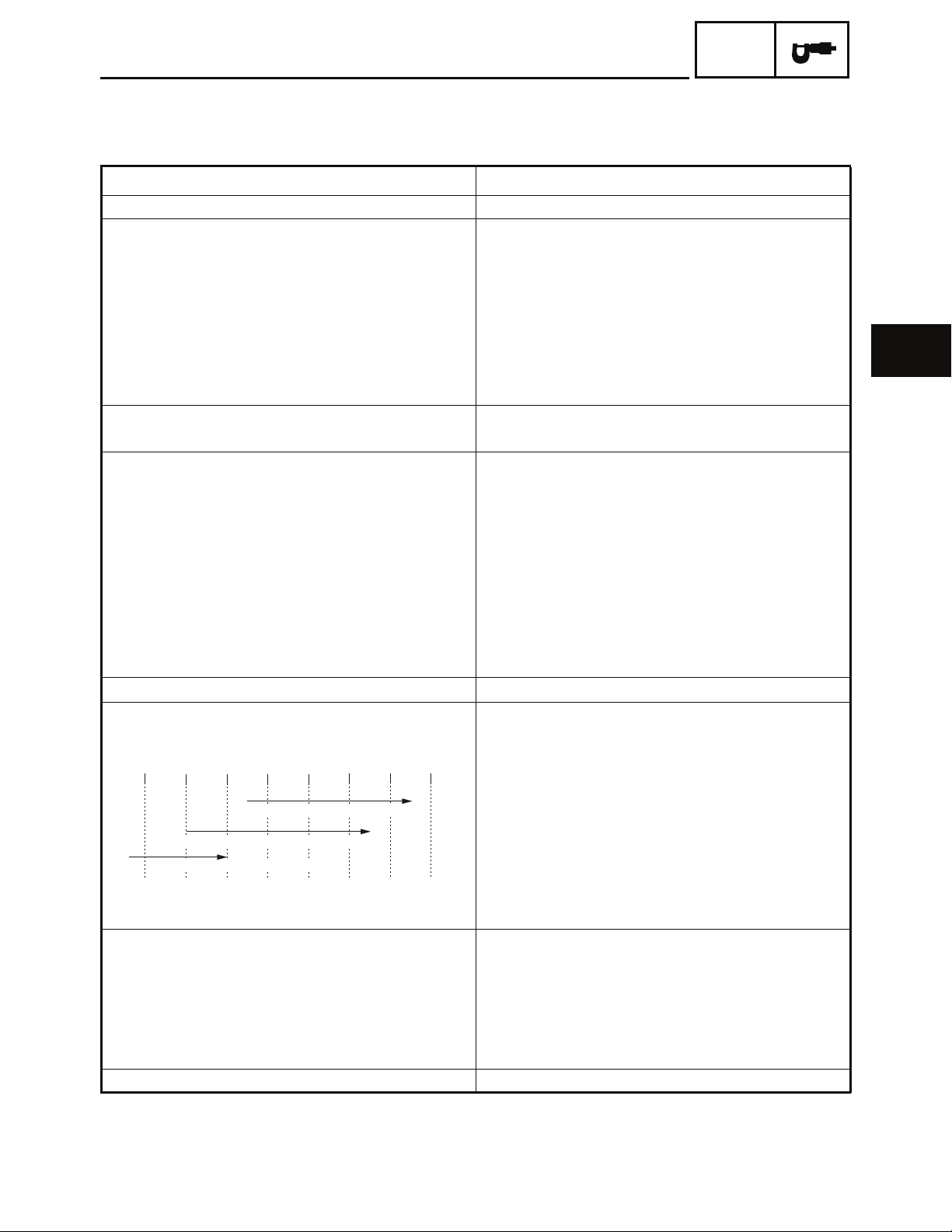
EBS00026
OIL FLOW DIAGRAMS
Camshaft
1
Crankshaft
2
Oil pump
3
Oil filter
4
OIL FLOW DIAGRAMS
SPEC
2 - 21
Page 44

EBS00028
CABLE ROUTING
Front brake cables
Rear brake hose
Parking brake cable
Throttle cable
Choke cable
Fuel tank breather hose Oil catch hose
Final gear case breather hose
Air filter case check hose
Fuel hose
Throttle valve hose
Fuel overflow hose
Carburetor air vent hose
Crankcase breather hose
CABLE ROUTING
15
0
A
B
C
SPEC
Fuel drain hose
Wire harness
Rear brake switch lead
Handlebar switch lead
Carburetor warmer lead
A
B
C
B
D
A
E
F
G
J
0
C
A
I
15
A
H
A
K
A
2 - 22
Page 45

CABLE ROUTING
EBS00028
Pass the front brake cables, parking brake cable, throttle cable and choke cable through the hose guide.
A
Fasten the choke cable, handlebar switch lead and rear brake switch lead with a plastic band.
B
Insert the fuel tank breather hose into the hole in the handlebar cover.
C
Fasten the carburetor warmer lead with a plastic band.
D
Fasten rear brake hose, parking brake cable and throttle cable with a plastic band.
E
Insert the final gear case breather hose into the hole in the fuel tank bracket.
F
SPEC
B
A
B
A
J
C
D
E
F
G
0
C
A
I
15
A
H
A
K
A
2 - 23
Page 46

CABLE ROUTING
Fasten rear brake hose and parking brake cable with a plastic band.
G
Fasten the fuel overflow hose and carburetor air vent hose with a metal band. Be sure to not pinch the hose.
H
Fasten the fuel drain hose with a metal band. Be sure to not pinch the hose.
I
Fasten the rear brake hose and choke cable with a plastic band.
J
Pass the rear brake hose through the hose guide.
K
SPEC
B
A
B
A
J
C
D
E
F
G
0
C
A
I
15
A
H
A
K
A
2 - 24
Page 47

CABLE ROUTING
SPEC
Rear brake hose
Throttle cable
Parking brake cable
Front brake cables
6
Air filter case check hose
K
A
A
N
B
G
Wire harness0 Fuel drain hose
A Positive starter motor lead
B Positive battery lead
C Negative battery lead
Negative starter motor lead
D
Starter motorE
Generator leadF
G Main switch
C
L
B
B
B
H Thermo switch
I Ignition coil
J Rectifier/regulator
K
Starter relay
L
Battery
M
Main fuse
N
C.D.I. unit
A
0
J
I
M
H
0
A
0 A B C B
B
A
A
F
E
D
0
B
G
H
I
J
6
C BDEF
2 - 25
Page 48

CABLE ROUTING
A
Pass these leads through rear fender.
B
Fasten the wire harness, main switch lead, thermo switch lead and with a plastic band.
Fasten the wire harness and generator lead with a plastic band.
C
Fasten the wire harness, negative battery lead and starter motor lead with a plastic band.
D
Fasten the wire harness, positive battery lead, negative battery lead and negative starter motor lead with
E
a metal band.
Fixed the negative battery lead and negative starter motor lead by a bolt.
F
K
A
G
C
L
B
SPEC
A
A
0 A B C B
B
A
A
B
B
B
A
H
N
0
J
I
M
0
F
E
D
0
B
G
H
I
J
6
C BDEF
2 - 26
Page 49

CABLE ROUTING
Pass the positive battery lead, positive starter motor lead and starter relay lead through the hose guide.
G
Pass the positive battery lead through the hose guide.
H
Pass the negative battery lead through the hose guide.
I
J
Pass the positive battery lead, positive starter motor lead and wire harness through the hose guide.
K
A
G
C
L
B
SPEC
A
A
0 A B C B
B
A
A
B
B
B
A
H
N
0
J
I
M
0
F
E
D
0
B
G
H
I
J
6
C BDEF
2 - 27
Page 50

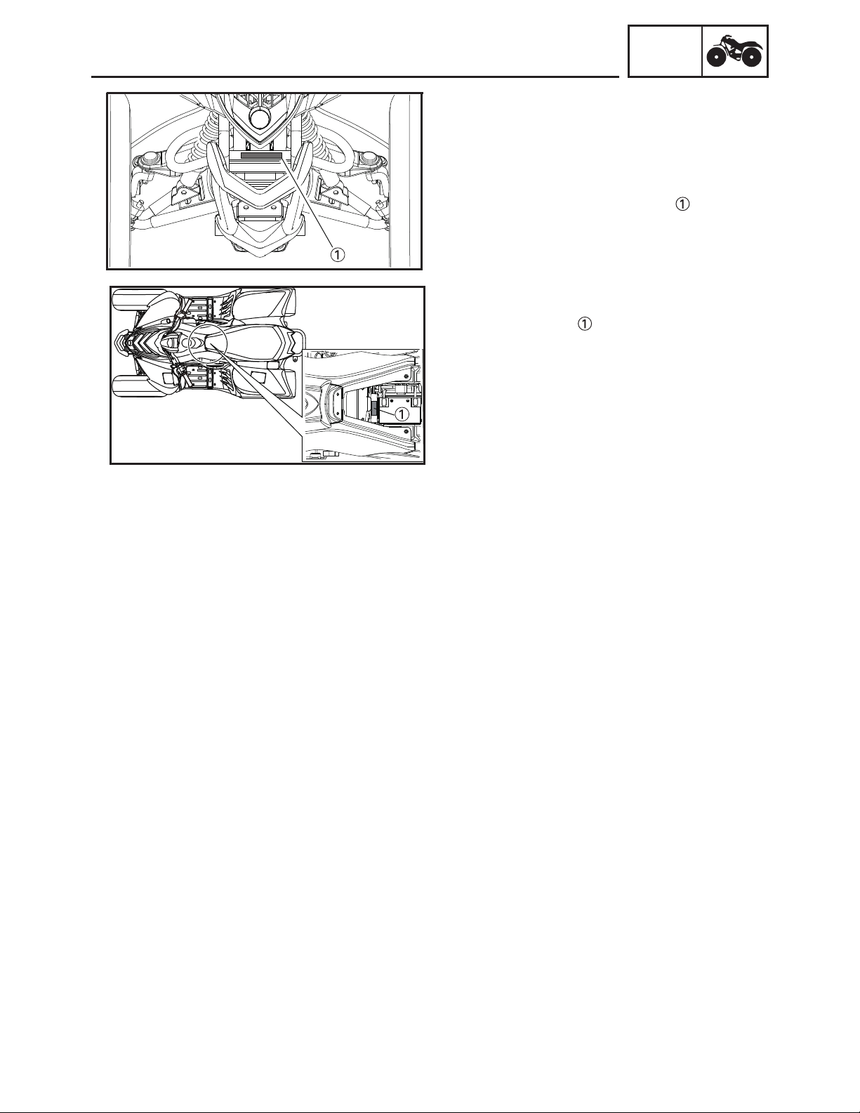
CABLE ROUTING
SPEC
1
Rear brake switch lead
2
Rear brake hose
3
Front brake cable (right)
4
Front brake cable (left)
5
Throttle cable
1
6
Parking brake cable
7
Fuel tank breather hose
8
Battery
9
Positive battery lead
10
Main fuse
A
2
11
Negative battery lead
12
Handlebar switch
13
Choke cable
3
4
5
12
A
13
6
7
8
B
C
9
G
11
10
D
E
F
2 - 28
A
Page 51

CABLE ROUTING
Fasten the handlebar switch lead , rear brake switch lead and choke cable with a plastic band.
A
B
Face the opening of the positive battery lead holder inward.
C
To starter relay.
D
Face the opening of the negative battery lead holder inward.
E
To the frame.
F
Connect the negative battery lead to the battery so that the lead is routed to the side of the battery.
G
Connect the positive battery lead to the battery so that the lead contacts the battery case.
A
2
1
3
4
SPEC
12
A
13
5
6
7
8
B
C
9
G
11
10
D
E
F
2 - 29
A
Page 52

CABLE ROUTING
9
1
2
Rear brake hose
3
Rear brake switch lead
4
Choke cable
Fasten the handlebar switch lead , rear brake switch lead and choke cable with a plastic band.
A
5
Handlebar switch lead Throttle cable
6
Oil catch hose
7
Crankcase breather hose
8
Parking brake cable
Front brake cable (left)
10
Front brake cable (right)
A Ignition coil
B Heater control Switch
SPEC
3
5
10
A
2
4
10
9
1
8
1
3
2
A
9
8
5
B
4
A
A
6
7
2 - 30
Page 53

INTRODUCTION/
PERIODIC MAINTENANCE/LUBRICATION
EBS00029
CHK
ADJ
PERIODIC CHECKS AND ADJUSTMENTS
INTRODUCTION
This chapter includes all information necessary to perform recommended checks and adjustments.
These preventive maintenance procedures, if followed, will ensure more reliable machine operation
and a longer service life. The need for costly overhaul work will be greatly reduced. This information
applies to machines already in service as well as to new machines that are being prepared for sale.
All service technicians should be familiar with this entire chapter.
EBS00030
PERIODIC MAINTENANCE CHART FORTHE EMISSIONCONTROL SYSTEM
INITIAL EVERY
NO. ITEM
Fuel line
1
*
2 Spark plug
Valves
3
*
Carburetor
4
*
Crankcase breather
*
5
system
Exhaust system
6
*
7 Spark arrester Clean. √ √ √
CHECK OR MAINTENANCE
JOB
Check fuel hoses for cracks or other damage, and
replace if necessary.
Check condition and clean, regap, or replace if
necessary.
Check valve clearance and adjust if necessary.
Check choke operation and correct if necessary.
Check engine idling speed and adjust if necessary.
Check breather hose for cracks or other damage,
and replace if necessary.
Check for leakage and replace gasket(s) if necessary.
Check for looseness and tighten all screw clamps
and joints if necessary.
Whichever comes
first
month 1 3 6 6 12
km
(mi)
hours 20 80 160 160 320
320
(200)
1300
(800)
√ √ √ √ √
√ √ √ √
2500
(1600)
√ √ √ √
2500
(1600)
√ √ √
√ √ √
√ √ √
5000
(3200)
3
GENERAL MAINTENANCE AND LUBRICATION CHART
INITIAL EVERY
NO. ITEM
1 Air filter element
Clutch
2
*
3
Front brake
*
4
Rear brake
*
5
Brake hoses
*
6 * Parking brake • Check operation and adjust if necessary.
7
Wheels
*
8
Tires
*
CHECK OR MAINTENANCE
JOB
Clean and replace if necessary.
Check operation.
Check operation and correct if necessary.
Check brake lever free play and adjust if necessary.
Replace brake shoes. Whenever worn to the limit
Check operation and correct if necessary.
Check fluid level and ATV for fluid leakage, and
correct if necessary.
Replace brake pads. Whenever worn to the limit
Check for cracks or other damage, and replace if
necessary.
Replace. Every 4years
Check runout and for damage, and replace if necessary.
Check tread depth and for damage, and replace if
necessary.
Check air pressure and balance, and correct if
necessary.
Whichever comes
first
month 1 3 6 6 12
km
(mi)
hours 20 80 160 160 320
320
(200)
Every 20–40 hours (more often in wet or
dusty areas)
1300
(800)
√ √ √ √
√ √ √ √ √
√ √ √ √ √
√ √ √ √
√ √ √ √ √
√ √ √ √
√ √ √ √
2500
(1600)
2500
(1600)
5000
(3200)
3 - 1
Page 54

PERIODIC MAINTENANCE/LUBRICATION
NO. ITEM
9 * Wheel hub bearings
10 * Chassis fasteners
Shock absorber
11 *
assemblies
Front knuckle piv-
12 *
ots
13 * Steering shaft
14 * Steering system
Engine oil
15
16
Engine oil strainer Clean.
17
Final transmission oil
Moving parts and
*
18
cables
Throttle lever hous-
*
19
ing and cable
Front and rear brake
*
20
switches
*
21
switches
22
V-belt
23
Drive chain
*
24
Drive chain rollers
INTRODUCTION/
CHECK OR MAINTENANCE
Check for looseness or damage, and replace if
necessary.
Make sure that all nuts, bolts, and screws are
properly tightened.
Check operation and correct if necessary.
Check for oil leakage and replace if necessary.
Lubricate with lithium-soap-based grease.
Lubricate with lithium-soap-based grease.
Check operation and repair or replace if damaged.
Check toe-in and adjust if necessary.
Change.
Check ATV for oil leakage, and correct if necessary.
Change.
Check ATV for oil leakage, and correct if neces-
sary.
• Lubricate.
• Check operation and correct if necessary.
• Check throttle cable free play and adjust if necessary.
• Lubricate throttle lever housing and cable.
• Check operation and correct if necessary.
• Check operation and correct if necessary.
Check operation
Check for wear,cracksor otherdamage, and replace
if necessary.
Check chain slack and adjust if necessary.
Check rear wheel alignment and correct if neces-
sary.
Clean and lubricate.
• Check for wear and replace if necessary.
JOB
Whichever comes
first
month 1 3 6 6 12
km
(mi)
hours 20 80 160 160 320
CHK
ADJ
INITIAL EVERY
320
1300
(200)
(800)
√ √ √
√ √ √
√ √
√ √ √
√ √ √
√ √ √
2500
(1600)
√ √ √ √
2500
(1600)
√√ √ √
√ √
√ √ √
√ √ √
√ √ √
√ √
√√ √ √
√√ √
√ √
√ √
√ √√ √ √
√√ √ √
√ √
√ √ √
5000
(3200)
TIP
The air filter needs more frequent service if you are riding in unusually wet or dusty areas.
Hydraulic brake service
Regularly check and, if necessary, correct the brake fluid level.
Every two years replace the brake master cylinder and caliper, and change the brake fluid.
Replace the brake hoses every four years and if cracked or damaged.
* Since these items require special tools, data and technical skills, have a Yamaha dealer perform
the service.
EBS00032
WARNING
Indicates a potential hazard that could result in serious injury or death.
3 - 2
Page 55

SEAT, FENDERS AND FUEL TANK
EBS00033
SEAT, FENDERS AND FUEL TANK
SEAT AND FRONT PANEL
5
3
4
2
CHK
ADJ
1
Order Job/Part Q’ty Remarks
Removing the seat and front panel
1 Seat 1
2 Front panel 1
3 Fuel tank breather hose 1
4 Handlebar cover 1
5 Cover 1 1
Remove the parts in the order listed.
TIP
Pull back the seat lock lever, than pull up
on the rear of the seat.
TIP
_
When installing the handlebar cover,
pass the fuel tank breather hose through
the hole in the handlebar cover.
3 - 3
Page 56

EBS00037
FRONT FENDER
SEAT, FENDERS AND FUEL TANK
1
CHK
ADJ
4
T
25 Nm (2.5m • kg,18.1 ft • Ib)
.
R
.
T
9 Nm (0.9 m • kg, 6.5 ft • Ib)
.
R
3
.
2
Order Job/Part Q’ty Remarks
Removing the front fender
Remove the parts in the order listed.
Seat and front panel Refer to “SEAT AND FRONT PANEL”.
1 Fuel tank top panel 1
2 Air cleaner joint clamp screw 1 Loosen.
3 Main switch 1
4 Front fender 1
For installation, reverse the removal procedure.
3 - 4
Page 57

SEAT, FENDERS AND FUEL TANK
EBS00039
REAR FENDER AND FOOTREST BOARDS
T
9 Nm (0.9 m • kg, 6.5 ft •Ib)
.
R
.
CHK
ADJ
T
9 Nm (0.9 m • kg, 6.5 ft • Ib)
.
R
.
4
T
9 Nm (0.9 m • kg, 6.5 ft • )bI
.
R
.
2
7
3
5
T
9 Nm (0.9 m • kg, 6.5 ft • Ib)
.
R
.
1
8
6
7
Order Job/Part Q’ty Remarks
Removing the rear fender and foot-
Remove the parts in the order listed.
rest boards
Seat Refer to “SEAT AND FRONT PANEL”.
Front fender Refer to “FRONT FENDER”.
1 Battery band 1
2 Wire harness and main fuse 1
3 Negative battery lead 1 Disconnect.
NOTICE
_
First disconnect the negative lead,
then disconnect the positive lead.
4 Positive battery lead 1 Disconnect.
5 Negative starter motor lead 1 Disconnect.
3 - 5
Page 58

T
9 Nm (0.9 m • kg, 6.5 ft •Ib)
.
R
.
SEAT, FENDERS AND FUEL TANK
T
9 Nm (0.9 m • kg, 6.5 ft • Ib)
.
R
.
CHK
ADJ
4
T
9 Nm (0.9 m • kg, 6.5 ft • )bI
.
R
.
2
7
3
5
T
9 Nm (0.9 m • kg, 6.5 ft • Ib)
.
R
.
1
8
6
7
Order Job/Part Q’ty Remarks
6 Battery
7 Footrest board
8 Rear fender
1
2
1
For installation, reverse the removal procedure.
3 - 6
Page 59

EBS00042
FUEL TANK
SEAT, FENDERS AND FUEL TANK
T
12 Nm (1.2 m • kg, 8.7 ft • Ib)
.
R
.
2
1
CHK
ADJ
3
T
9 Nm (0.9 m • kg, 6.5 ft • Ib)
.
R
.
3
Order Job/Part Q’ty Remarks
Removing the fuel tank
Remove the parts in the order listed.
Seat and front panel Refer to “SEAT AND FRONT PANEL”.
Front fender Refer to “FRONT FENDER”.
1 Fuel hose 1 Disconnect.
2 Fuel tank 1
3 Side cover 2
3 - 7
TIP
Before disconnecting the fuel hose, turn
the fuel cock to “OFF”.
For installation, reverse the removal pro-
cedure.
Page 60

ADJUSTING THE VALVE CLEARANCE
EAS00049
ENGINE
ADJUSTING THE VALVE CLEARANCE
The following procedure applies to all of the
valves.
TIP
•
Valve clearance adjustment should be
made on a cold engine, at room temperature.
•
When the valve clearance is to be measured or adjusted, the piston must be at
top dead center (TDC)on the compression
stroke.
1. Remove:
• C.D.I. magneto cover
• Cylinder head cover
Refer to “CYLINDER HEAD” in chapter 4.
CHK
ADJ
2. Measure:
• valve clearance
Out of specification
Valve clearance (cold)
Intake valve
0.07~0.10 mm (0.0027~0.0039 in)
Exhaust valve
0.07~0.10 mm (0.0027~0.0039 in)
a. Turn the crankshaft clockwise with a wrench.
b. Align the “T” mark on the rotor with the
stationary pointer on the crankcase.
T
When the “T” mark is aligned with the stationary pointer, the piston is at the Top Dead
Center (TDC).
TIP
• When the piston is at the Top Dead Center
(TDC) on the compression stroke, there
should be clearance between the valve stem
tips and their respective adjusting screws.
• Be sure to align the alignment mark on the
camshaft sprocket with hole mark is forwa-
rd to up.
→ Adjust.
3 - 8
Page 61

ADJUSTING THE VALVE CLEARANCE
c. Measure the valve clearance using a thick-
ness gauge .
Out of specification Adjust
Thickness gauge
90890-03079
Narrow gauge set
YM-34483
3. Adjust:
• valve clearance
a. Loosen the locknut .
b. Insert a thickness gauge between the
adjuster end and the valve end.
c. Turn the adjuster clockwise or counter-
clockwise with the tappet adjusting tool
until the proper clearance is obtained.
CHK
ADJ
Tappet adjusting tool (3 mm)
P/N. YM-08035, 90890-01311
d. Hold the adjuster to prevent it from moving
and then tighten the locknut.
Locknut
9 Nm (0.9 m · kg, 6.5 ft · lb)
T
.
R
.
e. Measure the valve clearance.
f. If the clearance is incorrect, repeat the
above steps until the proper clearance is
obtained.
4. Install:
• C.D.I. magneto cover
• Cylinder head cover
Refer to “CYLINDER HEAD” in chapter 4.
3 - 9
Page 62

ADJUSTING THE ENGINE IDLING SPEED
EBS00051
ADJUSTING THE ENGINE IDLING SPEED
1. Start the engine and let it warm up for several minutes.
2. Attach:
• engine tachometer
(to the spark plug lead)
Inductive self-powered tachometer
P/N. YU-8036-B
Engine tachometer
P/N. 90890-03113
3. Measure:
• engine idling speed
Out of specification Adjust.
Engine idling speed
1,600 ~ 1,800 r/min
CHK
ADJ
→
4. Adjust:
• engine idling speed
a. Turn the throttle stop screw in or out until
the specified idling speed is obtained.
Turning right
Turning left
5. Detach:
• engine tachometer
6. Adjust:
• throttle lever free play
Refer to “ADJUSTING THE THROTTLE
LEVER FREE PLAY”.
Throttle lever free play
1.0 ~ 3.0 mm (0.04 ~ 0.12 in)
Idling speed becomes
higher.
Idling speed becomes
lower.
3 - 10
Page 63

ADJUSTING THE THROTTLE LEVER FREE PLAY
EBS00052
ADJUSTING THE THROTTLE LEVER FREE
PLAY
TIP
_
Engine idling speed should be adjusted properly before adjusting the throttle lever free
play.
1. Measure:
a
• throttle lever free play
Out of specification → Adjust.
Throttle lever free play
1.0 ~ 3.0 mm (0.04 ~ 0.12 in)
2. Adjust:
• throttle lever free play
a. Pull back the adjuster cover .
b. Loosen the locknut on the carburetor
side.
c. Turn the adjuster in or out until the cor-
rect free play is obtained.
CHK
ADJ
a
Turning in Free play is increased.
Turning out Free play is decreased.
d. Tighten the locknut .
e. Push in the adjuster cover .
WARNING
_
After adjusting the free play, turn the handlebar to the right and left to make sure
that the engine idling speed does not
increase.
3 - 11
Page 64

ADJUSTING THE SPEED LIMITER
EBS00053
ADJUSTING THE SPEED LIMITER
The speed limiter keeps the carburetor throttle
from becoming fully-opened even when the
throttle lever is applied to the maximum position. Screwing in the adjuster stops the engine
speed from increasing.
1. Measure:
a
• speed limiter length
Out of specification→ Adjust.
Speed limiter length
Less than 11.0mm (0.43 in)
2. Adjust:
• speed limiter length
a. Loosen the locknut .
b. Turn the adjuster in or out until the speci-
fied speed limiter length is obtained.
CHK
ADJ
a
Turning in
Turning out
c. Tighten the locknut.
WARNING
_
• Particularly for a beginner rider, the
speed limiter should be screwed in completely. Screw it out little by little as their
riding technique improves. Never remove
the speed limiter for a beginning rider.
• For proper throttle lever operation do not
turn out the adjuster more than 11.0 mm
(0.43 in). Also, always adjust the throttle
lever free play to 1.0 ~ 3.0 mm (0.04 ~
0.12 in).
Speed limiter length is
decreased.
Speed limiter length is
increased.
3 - 12
Page 65

CHECKING THE SPARK PLUG
EBS00057
CHECKING THE SPARK PLUG
1. Remove:
• spark plug
2. Check:
• spark plug type
Incorrect→Change.
Standard spark plug
CR7HSA/NGK
3. Check:
• electrode
Wear/damage→ Replace.
• insulator
Abnormal color→ Replace.
Normal color is a medium-to-light tan color.
4. Clean:
• spark plug
(with a spark plug cleaner or wire brush)
CHK
ADJ
5. Measure:
• spark plug gap
a
Use a wire gauge or thickness gauge.
Out of specification→Regap.
Spark plug gap
0.6 ~ 0.7 mm (0.024 ~ 0.028 in)
6. Tighten:
• spark plug
TIP
_
T
11 Nm (1.1 m · kg, 8.0 ft · lb)
.
R
.
Before installing a spark plug, clean the gasket
surface and plug surface.
3 - 13
Page 66

CHECKING THE IGNITION TIMING
EBS00058
CHECKING THE IGNITION TIMING
TIP
Engine idling speed and throttle cable free play
should be adjusted properly before checking
the ignition timing.
1. Remove:
• Shroud cap
2. Attach:
• engine tachometer
• timing light
a
(to spark plug lead)
a
Inductive self-powered tachometer
P/N. YU-8036-B
Engine tachometer
P/N. 90890-03113
Timing light
P/N. YM-33277-A, 90890-03141
CHK
ADJ
T
F
3. Check:
• ignition timing
a. Warm up the engine and keep it at the
specified speed.
Engine speed
1,600 ~ 1,800 r/min
b. Visually check the stationary pointer to
verify it is within the required firing range
indicated on the rotor.
Incorrect firing range Check the pickup
coil.
4. Detach:
• timing light
• engine tachometer
5. Install:
• Shroud cap
TIP
The ignition timing is not adjustable.
→
3 - 14
Page 67

MEASURING THE COMPRESSION PRESSURE
EBS00061
MEASURING THE COMPRESSION
PRESSURE
TIP
Insufficient compression pressure will result in
a loss of performance.
1. Measure:
• valve clearance
Out of specification→ Adjust.
Refer to “ADJUSTING THE VALVE
CLEARANCE”.
2. Start the engine, warm it up for several minutes, and then turn it off.
3. Disconnect:
• spark plug cap
4. Remove:
• spark plug
CHK
ADJ
NOTICE
Before removing a spark plug, use compressed air to blow away any dirt accumulated in the spark plug well to prevent it
from falling into the cylinder.
5. Attach:
compression gauge
•
Compression gauge
90890-03081
YU-33223
Extension
90890-04082
6. Measure:
• compression pressure
Out of specification
and (d).
Compression pressure (at sea
level)
Minimum
1,050 kPa/1,000 r/min
(10.5 kg/cm
Standard
1,250 kPa/1,000 r/min
(12.5 kg/cm
Maximum
1,350 kPa/1,000 r/min
(13.5 kg/cm
→
Refer to steps (c)
2
, 152.3 psi)
2
, 181.3 psi)
2
, 195.8psi)
3 - 15
Page 68

MEASURING THE COMPRESSION PRESSURE
a. Set the main switch to “ON”.
b. With the throttle wide open, crank the
engine until the reading on the compression
gauge stabilizes.
WARNING
_
To prevent sparking, ground the spark plug
lead before cranking the engine.
c. If the compression pressure is above the
maximum specification, check the cylinder
head, valve surfaces and piston crown for
carbon deposits.
Carbon deposits → Eliminate.
d. If the compression pressure is below the
minimum specification, squirt a few drops of
oil into the cylinder and measure again.
Refer to the following table.
CHK
ADJ
Compression pressure
(with oil applied into the cylinder)
Reading Diagnosis
Higher than
without oil
Piston ring(s) wear
or damage →
Repair.
Piston, valves,
Same as without
oil
cylinder head
gasket or piston
possibly defective
→ Repair.
7. Install:
• spark plug
T
11 Nm (1.1 m · kg, 8.0 ft · lb)
.
R
.
8. Connect:
• spark plug cap
3 - 16
Page 69

CHECKING THE ENGINE OIL LEVEL
a
b
EBS00064
CHECKING THE ENGINE OIL LEVEL
1. Place the machine on a level surface.
2. Check:
• engine oil level
Oil level should be between the maximum
mark and minimum mark.
a
Oil level low→ Add oil to the proper level.
TIP
Do not screw the dipstick in when checking
the oil level.
a. Warm up the engine for several minutes,
and stop it, then wait at least several minutes for the oil to drain back into the crankcase.
WARNING
Never remove the dipstick just after high
speed operation because the heated oil
could spurt out. Wait until the oil cools
down before removing the dipstick.
CHK
ADJ
b
0
SAE 5W-30
-20
10 30
YAMALUBE 4 (10W-40) or SAE 10W-40
-10 0
50
YAMALUBE 4 (20W-50) or SAE 20W-50
10
90
70
30 40 50 °C
20
110
130 °F
b. Screw the dipstick completely out, and
wipe the dipstick clean, then just rest the
dipstick in the hole.
c. Pull up the dipstick, and check the oil level
whether or not it is between maximum
and minimum level .
b
a
d. If the level is lower, add the oil up to the
proper level.
Recommended oil
Follow the chart on the left.
TIP
Recommended oil classification:
API service SG type or higher, JASO standard
MA.
NOTICE
• Do not add any chemical additives.
Engine oil also lubricates the clutch and
additives could cause clutch slippage.
• Do not allow foreign material to enter the
crankcase.
3 - 17
Page 70

CHANGING THE ENGINE OIL
EBS00068
CHANGING THE ENGINE OIL
1. Start the engine, warm it up for several min-
utes, and then turn it off.
2. Place a container under the engine oil drain
bolt.
3. Remove:
• dipstick
• engine oil drain bolt
(along with the O-ring, spring and oil filter
screen)
4. Drain:
• engine oil
(completely from the crankcase)
5. Check:
• engine oil drain bolt gasket
Damage
→ Replace.
CHK
ADJ
6. Install:
• engine oil drain bolt
(along with the O-ring, spring and oil filter
screen)
T
8 Nm (0.8 m · kg, 5.8 ft · lb)
.
R
.
7. Fill:
• crankcase
(with the specified amount of the recommended engine oil)
Quantity
Total amount
0.80 L (0.70 Imp qt, 0.85 US qt)
Periodic oil change
0.75 L (0.66 Imp qt, 0.80 US qt)
8. Install:
• dipstick
9. Start the engine, warm it up for several minutes, and then turn it off.
10.Check:
• engine
(for engine oil leaks)
11.Check:
• engine oil level
Refer to “CHECKING THE ENGINE OIL
LEVEL”.
12.Check:
• oil lubrication by oil check bolt
3 - 18
Page 71

CLEANING THE AIR FILTER ELEMENT
EBS00071
CLEANING THE AIR FILTER ELEMENTS
TIP
There is a check hose at the bottom of the
air filter case. If dust and/or water collects in
this hose, clean the air filter elements and air filter case.
1. Remove:
• air filter case covers
CHK
ADJ
2. Loosen:
• bolt
3. Remove:
•
air filter element holders
• sponge materials
NOTICE
The engine should never be run without the
•
air filter; excessive piston and/or cylinder
wear may result.
This model is equipped with two air filter
•
elements: one located on the left side and
one located on the right side of the air box.
4. Check:
• sponge materials
Damaged → Replace.
5. Clean:
• sponge materials
a. Wash the sponge materials gently, but
thoroughly in solvent.
3 - 19
WARNING
_
Use a cleaning solvent which is designed
to clean parts only. Never use gasoline or
low flash point solvents as they may cause
a fire or explosion.
Page 72

CLEANING THE AIR FILTER ELEMENT/
CLEANING THE SPARK ARRESTER
b. Squeeze the excess solvent out of the spo-
nge materials and let it dry.
NOTICE
Do not twist or wring out the sponge materials.
could damage the sponge materials.
c. Apply Yamaha foam air filter oil or other quality
foam air filter oil to the sponge materials.
d. Squeeze out the excess oil.
TIP
The sponge materials should be wet but not
dripping.
6. Install:
• Sponge materials
• Air filter element holders
7. Tighten:
• bolt
8. Install:
• Air filter case covers
CHK
ADJ
TIP
Make sure its sealing surface matches the
sealing surface of the case so there is no air
leak.
CLEANING THE SPARK ARRESTER
1. Clean:
• spark arrester
WARNING
• Select a well-ventilated area free of combustible materials.
• Always let the exhaust system cool
before performing this operation.
• Do not start the engine when removing
l .relffum morf epipliat eht
a. Remove the bolt and nut
b. Remove the spark arrester by pulling it
out of the muffler.
3 - 20
Page 73

CLEANING THE SPARK ARRESTER
c. Tap the tailpipe lightly with a soft-face ham-
mer or suitable tool, then use a wire brush
to remove any carbon deposits from the
spark arrester portion of the tailpipe and the
inner contact surfaces of the muffler.
d. Insert the spark arrester into the muffler and
align the screw holes.
e. Insert the bolt, nut and tighten it.
Screw
5 Nm (0.5 m · kg, 3.6 ft · lb)
T
.
R
.
CHK
ADJ
3 - 21
Page 74

CHECKING THE FRONT BRAKE SHOES /
ADJUSTING THE FRONT BRAKE
CHK
ADJ
a
CHECKING THE FRONT BRAKE SHOES
1. Check:
•
Upper adjusting bolt
Lower adjusting bolt•
a
a
As more than 12 mm (0.47 in)
→
the brake shoes as a set.
Refer to “FRONT BRAKES” in chapter 6.
EBS00082
ADJUSTING THE FRONT BRAKE
TIP
Before adjusting the front brake, the front
_
brake linings should be checked.
NOTICE
_
Proper lever free play is essential to avoid
excessive brake drag.
Replace
a
CHASSIS
1. Measure:
• front brake lever free play
a
Out of specification→ Adjust.
Front brake lever free play
4 ~ 6 mm (0.16 ~ 0.24 in)
2. Adjust:
• front brake lever free play
a. Loosen the locknuts .
b
b. Turn the adjusters in or out until the
specified front brake lever free play is
obtained.
TIP
Make sure that the difference between clearances and is less than 2 mm when the
b
c
front brake lever is squeezed.
c
c. Tighten the locknuts.
3 - 22
Page 75

ADJUSTING THE PARKING BRAKE
ADJUSTING THE PARKING BRAKE
1. Check:
• parking brake cable end length
Out of specification → Adjust.
Parking brake cable end length
53.0 ~ 57.0 mm (2.09 ~ 2.24 in)
2. Adjust:
• parking brake cable end length
a. Loosen the locknut and adjusting bolt .
b. Loosen the locknut .
c. Turn the adjusting nut in direction or
until the specified brake cable end
length is obtained.
d. Tighten the locknut.
e. Slowly turn the adjusting bolt clockwise until
resistance is felt.
f. Turn it 1/8 counterclockwise.
g. Tighten the locknut .
CHK
ADJ
16 Nm (1.6 m•kg, 11 ft•lb)
WARNING
After this adjustment is performed, lift the
rear wheels off the ground by placing a
block under the engine, and spin the rear
wheels to ensure there is no brake drag. If
any brake drag is noticed perform the
above steps again.
3 - 23
Page 76

CHECKING THE REAR BRAKE FLUID LEVEL
EBS00087
CHECKING THE REAR BRAKE FLUID LEVEL
1. Place the machine on a level surface.
TIP
When checking the brake fluid level, make sure
that the top of the brake master cylinder reservoir or brake fluid reservoir is horizontal.
2. Check:
• brake fluid level
Below the minimum level mark → Add
the recommended brake fluid to the proper
level.
Recommended brake fluid
DOT 4
CHK
ADJ
WARNING
•Use only the designated brake fluid.
Other brake fluids may cause the rubber
seals to deteriorate, causing leakage and
poor brake performance.
•Refill with the same type of brake fluid that
is already in the system. Mixing brake fluids may result in a harmful chemical reaction, leading to poor brake performance.
•When refilling, be careful that water does
not enter the brake fluid reservoir. Water
will significantly lower the boiling point of
the brake fluid and could cause vapor
lock.
NOTICE
Brake fluid may damage painted surfaces
and plastic parts. Therefore, always clean
up any spilt brake fluid immediately
TIP
In order to ensure a correct reading of the
brake fluid level, make sure that the top of the
brake master cylinder reservoir or brake fluid
reservoir is horizontal.
3 - 24
Page 77

CHECKING THE REAR BRAKE PADS/CHECKING THE BRAKE
HOSE/ BLEEDING THE HYDRAULIC BRAKE SYSTEM
EBS00089
CHECKING THE REAR BRAKE PADS
1. Check:
• brake pads
Wear indicators almost touch the brake disc
a
→ Replace the brake pads as a set.
Refer to “REAR BRAKE” in chapter 6.
CHK
ADJ
Brake pad wear limit
a
1.0 mm (0.04 in)
2. Operate the rear brake lever.
EBS00092
CHECKING THE BRAKE HOSE
1. Remove:
• seat
• front fender
Refer to “SEAT, FENDERS AND FUEL
TANK”.
2. Check:
• rear brake hose
Cracks/wear/damage → Replace.
3. Check:
• brake hose clamps
Loosen → Tighten.
4. Hold the machine in an upright position and
apply the rear brake.
5. Check:
• brake hose
Apply the brake lever times.
Fluid leakage→ Replace thehose or pipe.
Refer to “REAR BRAKE” in chapter 6.
6. Install:
• front fender
• seat
Refer to “SEAT, FENDERS AND FUEL
TANK”.
EBS00094
BLEEDING THE HYDRAULIC BRAKE
SYSTEM
WARNING
Bleed the hydraulic brake system whenever:
•the system is disassembled.
•a brake hose is loosened, disconnected or
replaced.
•the brake fluid level is very low.
•brake operation is faulty.
3 - 25
Page 78

BLEEDING THE HYDRAULIC BRAKE SYSTEM
TIP
•Be careful not to spill any brake fluid or allow
the brake master cylinder reservoir or brake
fluid reservoir to overflow.
•When bleeding the hydraulic brake system,
make sure there is always enough brake fluid
before applying the brake. Ignoring this precaution could allow air to enter the hydraulic
brake system, considerably lengthening the
bleeding procedure.
•If bleeding is difficult, it may be necessary to
let the brake fluid settle for a few hours.
Repeat the bleeding procedure when the tiny
bubbles in the hose have disappeared.
1. Bleed:
• hydraulic brake system
a. Fill the brake fluid reservoir to the proper
level with the recommended brake fluid.
b. Install the diaphragm (brake master cylin-
der reservoir or brake fluid reservoir).
c. Connect a clear plastic hose tightly to
the bleed screw .
d. Place the other end of the hose into a con-
tainer.
e. Slowly apply the brake lever several times.
f. Fully squeeze the brake lever and hold it in
position.
g. Loosen the bleed screw.
TIP
Loosening the bleed screw will release the
pressure and cause the brake lever to contact
the grip.
CHK
ADJ
h. Tighten the bleed screw and then release
the brake lever.
i. Repeat steps (e) to (h) until all of the air
bubbles have disappeared from the brake
fluid in the plastic hose.
j. Tighten the bleed screw to specification.
5 Nm (0.5 m•kg, 3.7 ft•lb)
k. Fill the brake fluid reservoir to the proper
level with the recommended brake fluid.
Refer to “CHECKING THE REAR BRAKE
FLUID LEVEL”.
WARNING
After bleeding the hydraulic brake system,
check the brake operation.
3 - 26
Page 79

CHANGING THE FINAL TRANSMISSION OIL/
ADJUSTING THE DRIVE CHAIN SLACK
EBS00102
CHANGING THE FINAL TRANSMISSION OIL
1. Place the machine on a level surface.
2. Placea receptacle under the finaltransmission
case.
3. Remove:
• dipstick
• final transmission oil drain plug
4. Drain:
• final transmission oil
5. Install:
• final transmission oil drain plug
T
15 Nm (1.5 m·kg, 10.8 ft·lb)
.
R
.
TIP
_
Check the gasket (drain plug). If it is damaged,
replace it with a new one.
6. Fill:
• final transmission case
CHK
ADJ
Total amount
0.30 L (0.27 Imp qt, 0.32 US qt)
Recommended oil
SAE80 API “GL-4” Hypoid gear
oil
NOTICE
_
Take care not to allow foreign material to
enter the final gear case.
7. Install:
• dipstick
ADJUSTING THE DRIVE CHAIN SLACK
TIP
• Measure the drive chain slack halfway
between the drive axle and the rear axle.
• When checking and adjusting the drive chain
slack, there should be no weight on the vehicle and all tires must be touching the ground.
3 - 27
NOTICE
A drive chain that is too tight will overload
the engine and other vital parts, and one
that is too loose can skip and damage the
swingarm or cause an accident. Therefore,
keep the drive chain slack within the specified limits.
Page 80

ADJUSTING THE DRIVE CHAIN SLACK
1. Measure:
• drive chain slack
Out of specification → Adjust.
CHK
ADJ
a
a
Drive chain slack
10 ~ 25 mm (0.39 ~ 0.98 in)
2. Adjust:
• drive chain slack
3
2
1
a
b
TIP
The drive chain slack is adjusted by the rotation of the rear axle hub.
a. Loosen the rear axle pinch bolts .
b. Loosen the locknut .
2
1
c. To tighten the drive chain, turn the drive chain
adjusting nut indirection . To loosen the
3
a
drive chain, turn the drive chain adjusting nut
indirection .
b
NOTICE
Excessive chain slack will overload the
engine and other vital parts; keep the slack
within the specified limits.
d. Tighten the locknut.
e. Tighten the rear wheel axle pinch bolts.
55 Nm (5.5 m•kg, 39.8 ft•lb)
TOP
•The chain should be cleaned and lubricated
after every use of the vehicle.
3 - 28
Page 81

CHECKING THE STEERING SYSTEM
EBS00107
CHECKING THE STEERING SYSTEM
1. Place the machine on a level surface.
2. Check:
• steering shaft bushings and bearings
Move the handlebar up and down, and/or
back and forth.
Excessive play → Replace the steering
shaft bushings and or bearings.
Refer to “STEERING SYSTEM” in chapter
6.
3. Check:
• tie-rod ends
Turn the handlebar to the left and/or right
until it stops completely, then slightly move
the handlebar slightly in the opposite direction.
Tie-rod end(s) have vertical play
Replace the tie-rod end(s).
Refer to “STEERING SYSTEM” in chapter
6.
4. Raise the front end of the machine so that
there is no weight on the front wheels.
CHK
ADJ
→
3 - 29
5. Check:
•
ball joints and/or wheel bearings
Move the wheels laterally back and forth.
Excessive free play →Replace the front arms
(upper and lower) and/or wheel bearings.
Page 82

ADJUSTING THE TOE-IN
EBS00108
ADJUSTING THE TOE-IN
1. Place the machine on a level surface.
2. Measure:
• toe-in
Out of specification → Adjust.
Toe-in
15 mm (0.59 in)
TIP
Before measuring the toe-in, make sure that
the tire pressure is correct.
a. Mark both front tire tread centers.
b. Face the handlebar straight ahead.
c. Measure the width between the marks.
d. Rotate the front tires 180° until the marks
are exactly opposite one another.
e. Measure the width between the marks.
f. Calculate the toe-in using the formula given
below.
CHK
ADJ
Toe-in = –
g. If the toe-in is incorrect, adjust it.
Forward
3. Adjust:
• toe-in
WARNING
•Be sure that both tie-rods are turned the
same amount. If not, the machine will drift
right or left even though the handlebar is
positioned straight. This may lead to mishandling and an accident.
•After setting the toe-in to specification,
run the machine slowly for some distance
with both hands lightly holding the handlebar and check that the handlebar
responds correctly. If not, turn either the
right or left tie-rod within the toe-in specification.
3 - 30
Page 83

ADJUSTING THE TOE-IN/CHECKING THE FRONT AND
REAR SHOCK ABSORBERS
a. Mark both tie-rods ends.
This reference point will be needed during
adjustment.
b. Loosen the locknuts (tie-rod end) of both
tie-rods.
c. The same number of turns should be given
to both the right and left tie-rods until the
specified toe-in is obtained. This is to keep
the length of the rods the same.
d. Tighten the rod end locknuts of both tie-
rods.
TIP
Adjust the rod ends so that A and B are equal.
T
35 Nm (3.5 m · kg, 25.3 ft · lb)
.
R
.
CHK
ADJ
A
EBS00109
CHECKING THE FRONT AND REAR SHOCK
ABSORBERS
1. Place the machine on a level surface.
2. Check:
• damper rod
Bends/damage → Replace the front/rear
shock absorber assembly.
• oil leakage
Excessive oil leakage → Replace the front/
rear shock absorber assembly.
• cylinder
B
Damage → the front/rear shock absorber
assembly.
• spring
Fatigue → the front/rear shock absorber
assembly.
Refer to “FRONT ARMS AND FRONT
SHOCK ABSORBER ASSEMBLIES” and
“REAR SHOCK ABSORBER, SWINGARM
AND DRIVE CHAIN” in chapter 6.
3. Check:
• operation
Pump the shock absorbers up and down for
several times.
Unsmooth operation → Replace the front/
rear shock absorber assembly.
Refer to “ADJUSTING THE SHOCK
ABSORBERS”.
Front shock absorber
Rear shock absorber
3 - 31
Page 84

ADJUSTING THE SHOCK ABSORBERS
EBS00111
ADJUSTING THE SHOCK ABSORBERS
WARNING
Always adjust the spring preload of both
front shock absorbers to the same setting.
Uneven adjustment can result in poor handling and loss of stability.
CHK
ADJ
A
1. Adjust:
• spring preload
a. Turn the adjusting ring in direction or
b
with the spanner wrench
1
2
3
4
5
Direction
Spring preload is
a
increased (suspension is
.
a
harder).
Spring preload is
Direction
b
decreased (suspension is
softer).
Standard position: Front-2, Rear-1
Minimum position: 1
B
Maximum position: 5
Ring nut wrench
1
2
3
4
5
90890-01268
Spanner wrench
YU-01268
A
Front shock absorbers
3 - 32
B
Rear shock absorbers
Page 85

CHECKING THE TIRES
EBS00114
CHECKING THE TIRES
WARNING
_
This model is equipped with low pressure
tires. It is important that they be inflated
correctly and maintained at the proper
pressures.
• TIRE CHARACTERISTICS
1) Tire characteristics influence the handling of ATVs. The tires listed below
have been approved by Yamaha Motor
Co., Ltd. for this model. If other tire combinations are used, they can adversely
affect your machine’s handling characteristics and are therefore not recommended.
Manufacturer Size Type
CHK
ADJ
Front MAXXIS
Rear MAXXIS
AT18×
7-8
AT18×
9-8
M939
M940
• TIRE PRESSURE
1) Recommended tire pressure
2
Front 25 kPa (0.25 kgf/cm
Rear 25 kPa (0.25 kgf/cm
, 3.6 psi)
2
, 3.6 psi)
2) Tire pressure below the minimum specification could cause the tire to dislodge
from the rim under severe riding conditions.
The following are minimums:
Front 22 kPa (0.22 kgf/cm
Rear 22 kPa (0.22 kgf/cm
2
, 3.2 psi)
2
, 3.2 psi)
3) Use no more than
2
Front 250 kPa (2.5 kgf/cm
Rear 250 kPa (2.5 kgf/cm
, 36 psi)
2
, 36 psi)
when seating the tire beads. Higher
pressures may cause the tire to burst.
Inflate the tires slowly and carefully.
Fast inflation could cause the tire to
burst.
• MAXIMUM LOADING LIMIT
Vehicle load limits: 70.0 kg (154 lb)
*Total weight of the cargo, trailer hitch
vertical load, rider, and accessories.
3 - 33
Page 86

CHECKING THE TIRES
1. Measure:
• tire pressure
Out of specification → Adjust.
TIP
_
• The low-pressure tire gauge is included
as standard equipment.
• If dust or the like is stuck to this gauge, it will
not provide the correct readings. Therefore,
take two measurements of the tire’s pressure
and use the second reading.
CHK
ADJ
Cold tire
pressure
Standard
Minimum
Maximum
WARNING
_
Front Rear
25 kPa
(0.25 kgf/cm
2
,
3.6 psi)
22 kPa
2
(0.22 kgf/cm
,
3.2 psi)
25 kPa
(0.25 kgf/cm
2
,
3.6 psi)
25 kPa
(0.25 kgf/cm2,
3.6 psi)
22 kPa
(0.22 kgf/cm
3.2 psi)
25 kPa
(0.25 kgf/cm2,
3.6 psi)
2
Uneven or improper tire pressure may
adversely affect the handling of this
machine and may cause loss of control.
• Maintain proper tire pressures.
• Set tire pressures when the tires are cold.
• Tire pressures must be equal in both front
tires and equal in both rear tires.
,
3 - 34
Page 87

CHECKING THE TIRES/
CHECKING THE WHEELS
2. Check:
• tire surfaces
Wear/damage → Replace.
CHK
ADJ
Tire wear limit
a
Front and rear: 3 mm (0.12 in)
WARNING
_
It is dangerous to ride with a worn-out tire.
When tire wear is out of specification,
replace the tire immediately.
EBS00116
CHECKING THE WHEELS
1. Check:
• wheel
Damage/bends → Replace.
TIP
_
Always balance the wheel when a tire or wheel
has been changed or replaced.
WARNING
_
• Never attempt even small repairs to the
wheel.
• Ride conservatively after installing a tire
to allow it to seat itself properly on the
rim.
3 - 35
Page 88

CHECKING AND LUBRICATING THE CABLES/LUBRICATING THE
LEVERS, STEERING SHAFT AND STEERING KNUCKLES
EBS00117
CHECKING AND LUBRICATING THE
CABLES
WARNING
_
A damaged cable sheath may cause corrosion and interfere with the cable movement. An unsafe condition may result so
replace a damaged cable as soon as possible.
1. Check:
• cable sheath
Damage → Replace.
2. Check:
• cable operation
Unsmooth operation → Lubricate or
replace.
Recommended lubricant
Lithium-soap-base grease
CHK
ADJ
TIP
Hold the cable end up and apply several drops
of lubricant to the cable.
EBS00118
LUBRICATING THE LEVERS, STEERING
SHAFT AND STEERING KNUCKLES
Lubricate the pivoting point and metal-to-metal
moving parts of the levers, steering shaft and
steering knuckles.
Recommended lubricant
Lithium-soap-base grease
3 - 36
Page 89

CHECKING AND CHARGING THE BATTERY
EBS00120
ELECTRICAL SYSTEM
CHECKING AND CHARGING THE BATTERY
WARNING
Batteries generate explosive hydrogen gas
and contain electrolyte which is made of
poisonous and highly caustic sulfuric acid.
Therefore, always follow these preventive
measures:
•Wear protective eye gear when handling
or working near batteries.
•Charge batteries in a well-ventilated area.
•Keep batteries away from fire, sparks or
open flames (e.g., welding equipment,
lighted cigarettes).
•DO NOT SMOKE when charging or handling batteries.
•KEEP BATTERIES AND ELECTROLYTE
OUT OF REACH OF CHILDREN.
•Avoid bodily contact with electrolyte as it
can cause severe burns or permanent eye
injury.
FIRST AID IN CASE OF BODILY CONTACT:
EXTERNAL
•Skin — Wash with water.
•Eyes — Flush with water for 15 minutes
and get immediate medical attention.
INTERNAL
•Drink large quantities of water or milk followed with milk of magnesia, beaten egg
or vegetable oil. Get immediate medical
attention.
CHK
ADJ
NOTICE
•This is a sealed battery. Never remove the
sealing caps because the balance
between cells will not be maintained and
battery performance will deteriorate.
•Charging time, charging amperage and
charging voltage for an VRLA (Valve Regulated Lead Acid) battery are different
from those of conventional batteries. The
VRLA (Valve Regulated Lead Acid) battery
should be charged asexplained in the
charging method illustrations. If the battery
is overcharged, the electrolyte level will
drop considerably. Therefore, take special
care when charging the battery.
3 - 37
Page 90

CHECKING AND CHARGING THE BATTERY
TIP
Since VRLA (Valve Regulated Lead Acid)
batteries are sealed, it is not possible to check
the charge state of the battery by measuring
the specific gravity of the electrolyte. Therefore,
the charge of the battery has to be checked by
measuring the voltage at the battery terminals.
1. Remove:
• seat
• battery band
Refer to “SEAT, FENDERS AND FUEL
TANK”.
2. Disconnect:
• battery leads
(from the battery terminals)
NOTICE
First, disconnect the negative battery lead
, and then the positive battery lead .
CHK
ADJ
Relationshipbetween theopen-circuit voltage
and the charging time at 20 °C (68 °F)
Open-circuit voltage (V)
These values vary with the temperature, the condition of
the battery plates, and the electrolyte level.
Charging time (hours)
3. Remove:
• battery
4. Check:
• battery charge
a. Connect a pocket tester to the battery ter-
minals.
Positive tester probe →
positive battery terminal
Negative tester probe →
negative battery terminal
TIP
•The charge state of an VRLA (Valve Regulated
Lead Acid) battery can be checked by measuring its open-circuit voltage (i.e., the voltage
when the positive terminal is disconnected).
•No charging is necessary when the open-circuit voltage equals or exceeds 12.8 V.
b. Check the charge of the battery, as shown
in the charts and the following example.
3 - 38
Page 91

CHECKING AND CHARGING THE BATTERY
Example
c. Open-circuit voltage = 12.0 V
d. Charging time = 6.5 hours
e. Charge of the battery = 20 ~ 30%
CHK
ADJ
Charging
18
17
16
15
14
13
12
11
Open-circuit voltage (V)
10
Ambient temperature
20°C (68°F)
5. Charge:
• battery
(refer to the appropriate charging method
illustration)
WARNING
Do not quick charge a battery.
100 30
14
13
12
11
10
Open-circuit voltage (V)
100 75 50 30 25 20 0
Charging condition of the battery (%)
04 05 0620
Check the open-circuit
voltage.
Time (minutes)
Ambient
temperature
20°C (68°F)
NOTICE
•Never remove the VRLA (Valve Regulated
Lead Acid) battery sealing caps.
•Do not use a high-rate battery charger
since it forces a high-amperage current
into the battery quickly and can cause battery overheating and battery plate damage.
•If it is impossible to regulate the charging
current on the battery charger, be careful
not to overcharge the battery.
•When charging a battery, be sure to
remove it from the machine. (If charging
has to be done with the battery mounted
on the machine, disconnect the negative
battery lead from the battery terminal.)
•To reduce the chance of sparks, do not
plug in the battery charger until the battery charger leads are connected to the
battery.
•Before removing the battery charger lead
clips from the battery terminals, be sure to
turn off the battery charger.
•Make sure the battery charger lead clips
are in full contact with the battery terminal
and that they are not shorted. A corroded
battery charger lead clip may generate
heat in the contact area and a weak clip
spring may cause sparks.
•If the battery becomes hot to the touch at
any time during the charging process, disconnect the battery charger and let the
battery cool before reconnecting it. Hot
batteries can explode!
3 - 39
Page 92

CHECKING AND CHARGING THE BATTERY
•As shown in the following illustration, the
open-circuit voltage of an VRLA (Valve
Regulated Lead Acid) battery stabilizes
about 30 minutes after charging has been
completed. Therefore, wait 30 minutes after
charging is completed before measuring
the open-circuit voltage.
CHK
ADJ
3 - 40
Page 93

CHECKING AND CHARGING THE BATTERY
Charging method using a variable-current (voltage) charger
Charger
Ammeter
CHK
ADJ
YES
Adjust the voltage to obtain
the standard charging amperage.
Measure the open-circuit
voltage prior to charging.
Connect a charger and
ammeter to the battery
and start charging.
Is the amperage higher
than the standard charging amperage written on
the battery?
Adjust the charging voltage
to 20 ~ 25 V.
Monitor the amperage for 3 ~ 5
YES
minutes. Is the standard charging amperage exceeded?
Leave the battery unused for
more than 30 minutes before
measuring its open-circuit voltage.
Set the charging voltage to 16 ~
17 V. (If the charging voltage is
lower, charging will be insufficient,
if it is higher, the battery will be
over-charged.)
NO
If the amperage does not
Set the timer to the charging
time determined by the opencircuit voltage.
exceed the standard charging amperage after 5 minutes, replace the battery.
Refer to “CHECKING AND
CHARGING THE BATTERY”.
If the required charging time exceeds 5 hours, it is advisable to
check the charging amperage after 5 hours. If there is any change in
the amperage, readjust the voltage to obtain the standard charging
amperage.
Leave the battery unused for more than 30 minutes before measuring its open-circuit voltage.
12.8 V → Charging is complete.
12.0 ~ 12.7 V → Recharging is required.
Under 12.0 V → Replace the battery.
NO
3 - 41
Page 94

CHECKING AND CHARGING THE BATTERY
Charging method using a constant voltage charger
CHK
ADJ
YES
Charge the battery until the charging
voltage reaches 15 V.
TIP
Set the charging time to a maximum of 20 hours.
Measure the open-circuit
voltage prior to charging.
Connect a charger and
ammeter to the battery
and start charging.
Is the amperage higher
than the standard charging amperage written on
the battery?
This type of battery charger cannot
charge an VRLA battery. A variablevoltage charger is recommended.
TIP
Leave the battery unused for more
than 30 minutes before measuring
its open-circuit voltage.
NO
Leave the battery unused for more than 30
minutes before measuring its open-circuit
voltage.
12.8 V → Charging is complete.
12.0 ~ 12.7 V → Recharging is required.
Under 12.0 V → Replace the battery.
NOTICE
Constant amperage chargers are not
suitable for charging VRLA batteries.
Charger
Ammeter
Voltmeter
3 - 42
Page 95

CHECKING AND CHARGING THE BATTERY
6. Install:
• battery
7. Connect:
• battery leads
(to the battery terminals)
NOTICE
First, connect the positive battery lead ,
and then the negative battery lead .
8. Check:
• battery terminals
Dirt → Clean with a wire brush.
Loose connection → Connect properly.
9. Lubricate:
• battery terminals
CHK
ADJ
Recommended lubricant
Dielectric grease
10.Install:
• battery band
• seat
Refer to “SEAT, FENDERS AND FUEL
TANK”.
3 - 43
Page 96

CHECKING THE FUSES
EBS00121
CHECKING THE FUSES
The following procedure applies to all of the
fuses.
NOTICE
To avoid a short circuit, always set the main
switch to “OFF” when checking or replacing a fuse.
1. Remove:
• seat
Refer to “SEAT, FENDERS AND FUEL
TANK”.
CHK
ADJ
2. Check:
• fuse
a. Connect the pocket tester to the fuse and
check the continuity.
TIP
Set the pocket tester selector to “Ω × 1”.
Pocket tester
90890-03112
Analog pocket tester
YU-03112-C
b. If the pocket tester indicates “•”, replace the
fuse.
3. Replace:
• blown fuse
a. Set the main switch to “OFF”.
b. Install a new fuse of the correct amperage.
c. Set on the switches to verify if the electrical
circuit is operational.
d. If the fuse immediately blows again, check
the electrical circuit.
3 - 44
Page 97

CHECKING THE FUSES
CHK
ADJ
Items
Main 10 A 1
Reserve 10 A 1
Amperage
rating
Q’ty
WARNING
Never use a fuse with an amperage rating
other than that specified. Improvising or
using a fuse with the wrong amperage rating may cause extensive damage to the
electrical system, cause the lighting and
ignition systems to malfunction and could
possibly cause a fire.
4. Install:
• seat
Refer to “SEAT, FENDERS AND FUEL
TANK”.
3 - 45
Page 98

EBS00198
ENGINE
ENGINE
EXHAUST PIPE/MUFFLER, BREATHER HOSE AND LEADS
ENGINE
ENG
T
13 Nm (1.3 m • kg, 9.4 ft • lb)
.
R
.
4
5
T
25 Nm (2.5 m • kg, 18 ft • Ib)
.
R
.
1
3
2
6
7
8
Order Job/Part Q’ty Remarks
Removing the exhaust pipe/muffler,
Remove the parts in the order listed.
breather hose and leads
Rear fender Refer to “SEAT, FENDERS AND FUEL
TANK” in chapter 3.
1 Cover,chain case 1 1
2 Exhaust pipe/muffler 1
3 Exhaust pipe gasket 1
4 Spark plug lead 1
5 Generator lead 2
6 Negative starter motor lead 1
7 Carburator warmer lead 1
8 Crankcase breather hose 1
For installation, reverse the removal procedure.
4 - 1
Page 99

EBS00205
ENGINE MOUNTING BOLTS
2
ENGINE
ENG
3
T
35 Nm (3.5 m • kg, 23.5 ft •Ib)
.
R
.
4
2
3
4
1
T
35 Nm (3.5 m
.
R
.
• kg, 23.5 ft •Ib)
Order Job/Part Q’ty Remarks
Removing the engine mounting
Remove the parts in the order listed.
bolts
Carburetor Refer to “CARBURETOR” in chapter 5.
1 Drive chain 1
Refer to “REMOVING THE ENGINE”.
2 Lower engine mounting nut/bolt 1/1
3 Upper engine mounting nut/bolt 1/1
Refer to “INSTALLING THE ENGINE”.
4 Engine assembly 1
NOTICE
Install all of the bolts/nuts and then
tighten them to full torque specifications.
_
For installation, reverse the removal procedure.
4 - 2
Page 100

ENGINE
ENG
REMOVING THE ENGINE
1. Remove:
• master link
• drive chain
EBS00207
INSTALLING THE ENGINE
1. Install:
• upper engine mounting bolt/nut
• lower engine mounting bolt/nut
TIP
Do not fully tighten the bolts and nuts.
2. Tighten:
• upper engine mounting nut
T
35 Nm (3.5 m · kg, 25.3 ft · lb)
.
R
.
• lower engine mounting nut
T
35 Nm (3.5 m · kg, 25.3 ft · lb)
.
R
.
3. Install:
• drive chain
•
master link
TIP
The master link clip must be installed with the
rounded end facing the direction of travel.
4 - 3
 Loading...