

Page 1

2009
SERVICE MANUAL
YFM5FGY
YFM5FGPY
YFM7FGY
YFM7FGPY
LIT-11616-22-19 34D-28197-10
Page 2

EAS20050
YFM5FGY/YFM5FGPY/YFM7FGY/YFM7FGPY
SERVICE MANUAL
©2008 by Yamaha Motor Corporation, U.S.A.
First edition, May 2008
All rights reserved.
Any reproduction or unauthorized use
without the written permission of
Yamaha Motor Corporation, U.S.A.
is expressly prohibited.
Printed in U.S.A.
LIT-11616-22-19
Page 3
EAS20071
T
IMPORTANT
This manual was produced by the Yamaha Motor Company, Ltd. primarily for use by Yamaha dealers
and their qualified mechanics. It is not possible to include all the knowledge of a mechanic in one manual. Therefore, anyone who uses this book to perform maintenance and repairs on Yamaha vehicles
should have a basic understanding of mechanics and the techniques to repair these types of vehicles.
Repair and maintenance work attempted by anyone without this knowledge is likely to render the vehicle unsafe and unfit for use.
This model has been designed and manufactured to perform within certain specifications in regard to
performance and emissions. Proper service with the correct tools is necessary to ensure that the vehicle will operate as designed. If there is any question about a service procedure, it is imperative that you
contact a Yamaha dealer for any service information changes that apply to this model. This policy is
intended to provide the customer with the most satisfaction from his vehicle and to conform to federal
environmental quality objectives.
Yamaha Motor Company, Ltd. is continually striving to improve all of its models. Modifications and significant changes in specifications or procedures will be forwarded to all authorized Yamaha dealers and
will appear in future editions of this manual where applicable.
IP
• This Service Manual contains information regarding periodic maintenance to the emission control system. Please read this material carefully.
• Designs and specifications are subject to change without notice.
EAS20081
IMPORTANT MANUAL INFORMATION
Particularly important information is distinguished in this manual by the following notations.
This is the safety alert symbol. It is used to alert you to potential personal injury hazards. Obey all safety messages that follow this symbol to
avoid possible injury or death.
WARNING
NOTICE
TIP
A WARNING indicates a hazardous situation which, if not avoided, could
result in death or serious injury.
A NOTICE indicates special precautions that must be taken to avoid
damage to the vehicle or other property.
A TIP provides key information to make procedures easier or clearer.
Page 4
EAS20090
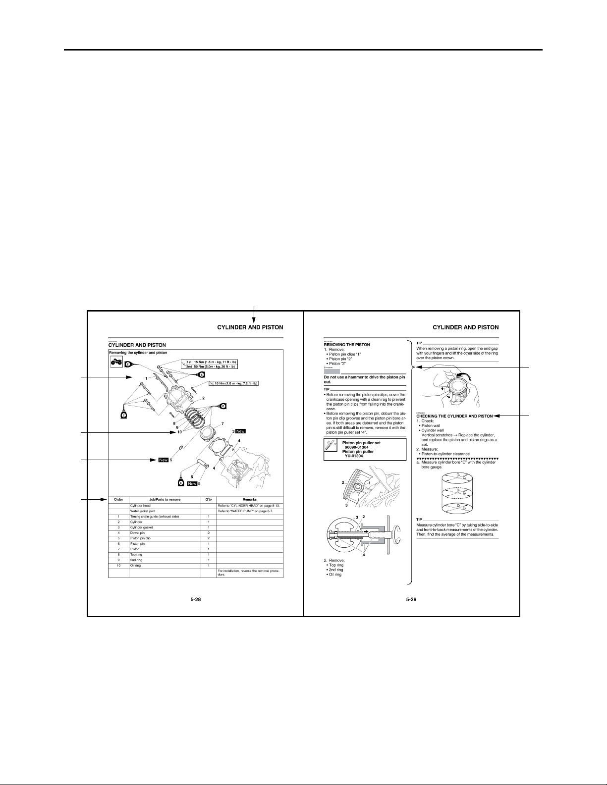
HOW TO USE THIS MANUAL
This manual is intended as a handy, easy-to-read reference book for the mechanic. Comprehensive
explanations of all installation, removal, disassembly, assembly, repair and check procedures are laid
out with the individual steps in sequential order.
• The manual is divided into chapters and each chapter is divided into sections. The current section title
“1” is shown at the top of each page.
• Sub-section titles “2” appear in smaller print than the section title.
• To help identify parts and clarify procedure steps, there are exploded diagrams “3” at the start of each
removal and disassembly section.
• Numbers “4” are given in the order of the jobs in the exploded diagram. A number indicates a disassembly step.
• Symbols “5” indicate parts to be lubricated or replaced.
Refer to “SYMBOLS”.
• A job instruction chart “6” accompanies the exploded diagram, providing the order of jobs, names of
parts, notes in jobs, etc.
• Jobs “7” requiring more information (such as special tools and technical data) are described sequentially.
1
3
NOTICE
7
2
4
5
6
Page 5
EAS20100
T
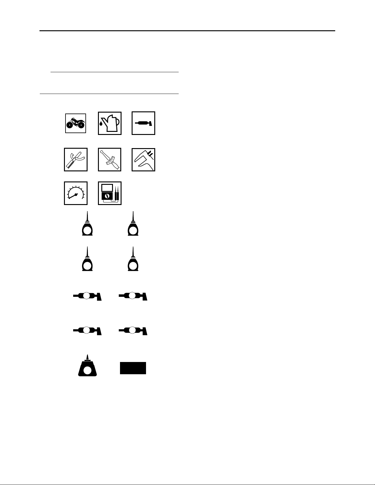
SYMBOLS
The following symbols are used in this manual
for easier understanding.
IP
The following symbols are not relevant to every
vehicle.
1 2 3
4 5 6
T
.
R
.
78
1. Serviceable with engine mounted
2. Filling fluid
3. Lubricant
4. Special tool
5. Tightening torque
6. Wear limit, clearance
7. Engine speed
8. Electrical data
9. Engine oil
10.Gear oil
11.Molybdenum disulfide oil
12.Brake fluid
13.Wheel bearing grease
14.Lithium-soap-based grease
15.Molybdenum disulfide grease
16.Silicone grease
17.Apply locking agent (LOCTITE®).
18.Replace the part with a new one.
9 10
E
11 12
M
13 14
B
15 16
M
17 18
LT
G
BF
LS
S
New
Page 6

Page 7
EAS20110
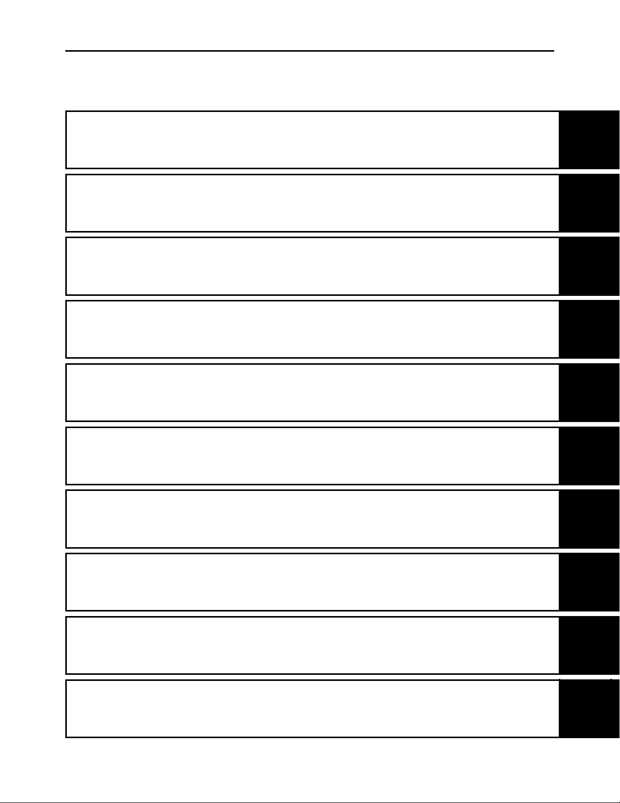
TABLE OF CONTENTS
GENERAL INFORMATION
SPECIFICATIONS
PERIODIC CHECKS AND
ADJUSTMENTS
CHASSIS
ENGINE
1
2
3
4
5
COOLING SYSTEM
FUEL SYSTEM
DRIVE TRAIN
ELECTRICAL SYSTEM
TROUBLESHOOTING
6
7
8
9
10
Page 8

Page 9

GENERAL INFORMATION
IDENTIFICATION ............................................................................................1-1
VEHICLE IDENTIFICATION NUMBER ..................................................... 1-1
MODEL LABEL..........................................................................................1-1
FEATURES...................................................................................................... 1-2
OUTLINE OF THE FI SYSTEM................................................................. 1-2
FI SYSTEM................................................................................................ 1-3
OUTLINE OF THE EPS (ELECTRIC POWER STEERING) SYSTEM
(YFM5FGP/YFM7FGP only)..................................................................... 1-5
EPS (ELECTRIC POWER STEERING) SYSTEM BLOCK DIAGRAM
(YFM5FGP/YFM7FGP only)..................................................................... 1-7
INSTRUMENT FUNCTIONS ..................................................................... 1-9
IMPORTANT INFORMATION .......................................................................1-11
PREPARATION FOR REMOVAL AND DISASSEMBLY......................... 1-11
REPLACEMENT PARTS......................................................................... 1-11
GASKETS, OIL SEALS AND O-RINGS .................................................. 1-11
LOCK WASHERS/PLATES AND COTTER PINS ...................................1-11
BEARINGS AND OIL SEALS ..................................................................1-12
CIRCLIPS ................................................................................................1-12
1
CHECKING THE CONNECTIONS ................................................................ 1-13
SPECIAL TOOLS .......................................................................................... 1-14
Page 10
EAS20130
IDENTIFICATION
EAS20140
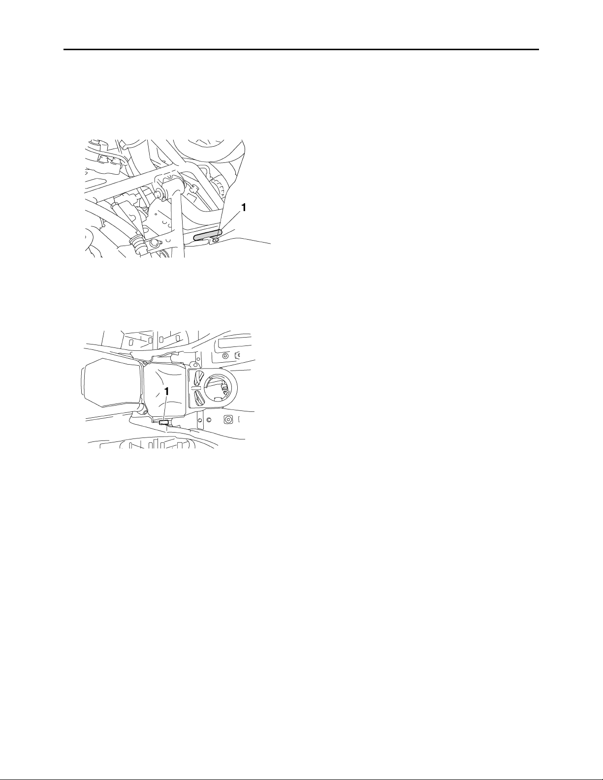
VEHICLE IDENTIFICATION NUMBER
The vehicle identification number “1” is stamped
into the front left side of the frame.
EAS20150
MODEL LABEL
The model label “1” is affixed to the location
shown in the illustration. This information will be
needed to order spare parts.
IDENTIFICATION
1-1
Page 11
FEATURES
EAS20170
FEATURES
EAS28P1031
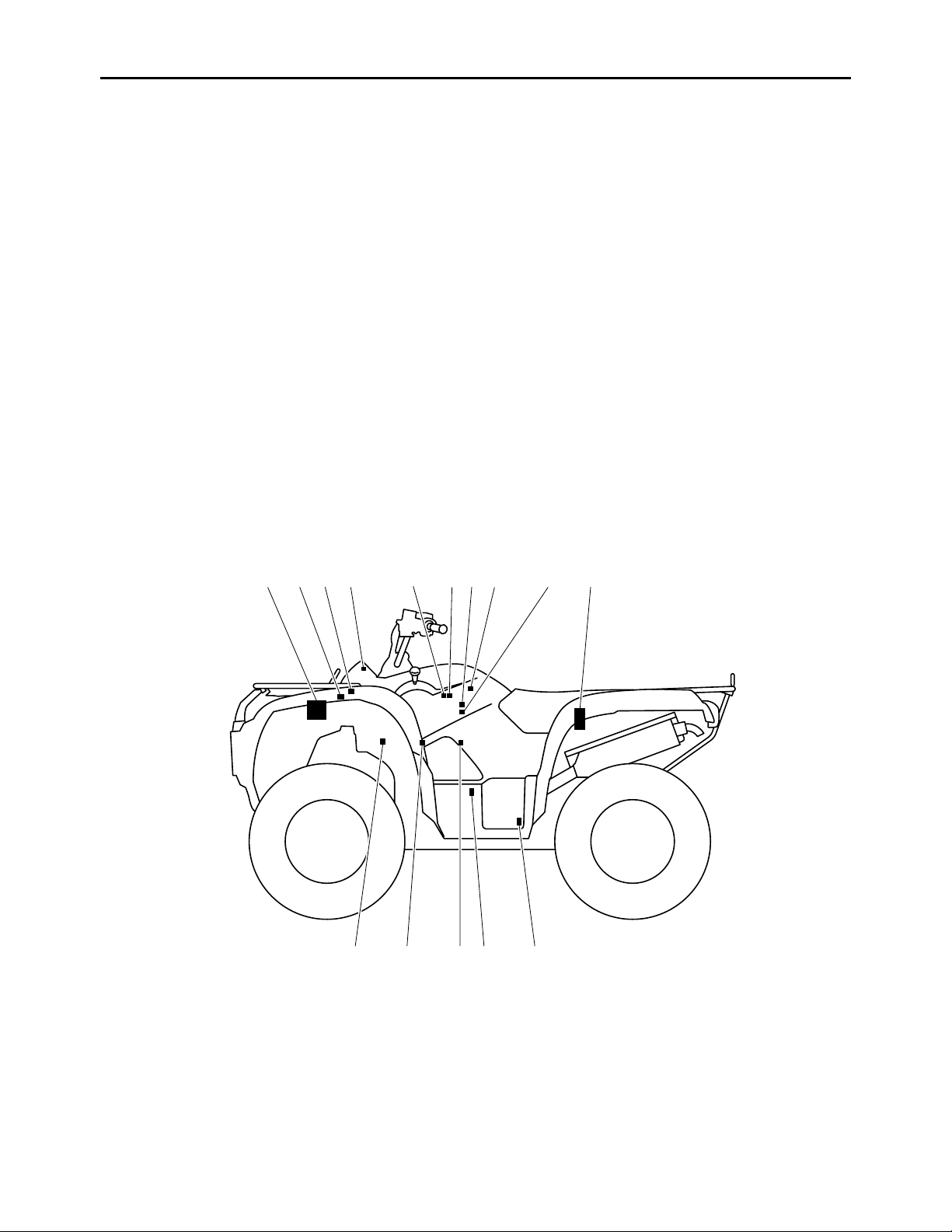
OUTLINE OF THE FI SYSTEM
The main function of a fuel supply system is to provide fuel to the combustion chamber at the optimum
air-fuel ratio in accordance with the engine operating conditions and the atmospheric temperature. In
the conventional carburetor system, the air-fuel ratio of the mixture that is supplied to the combustion
chamber is created by the volume of the intake air and the fuel that is metered by the jet used in the
respective carburetor.
Despite the same volume of intake air, the fuel volume requirement varies with the engine operating
conditions, such as acceleration, deceleration, or operating under a heavy load. Carburetors that meter
the fuel through the use of jets have been provided with various auxiliary devices, so that an optimum
air-fuel ratio can be achieved to accommodate the constant changes in the operating conditions of the
engine.
As the requirements for the engine to deliver more performance and cleaner exhaust gases increase,
it becomes necessary to control the air-fuel ratio in a more precise and finely tuned manner. To accommodate this need, this model has adopted an electronically controlled fuel injection (FI) system, in place
of the conventional carburetor system. This system can achieve an optimum air-fuel ratio required by
the engine at all times by using a microprocessor that regulates the fuel injection volume according to
the engine operating conditions detected by various sensors.
The adoption of the FI system has resulted in a highly precise fuel supply, improved engine response,
better fuel economy, and reduced exhaust emissions.
1 2 3 4 6 7 8 9 10
1. ECU (engine control unit)
2. Lean angle sensor
3. Fuel injection system relay
4. Engine trouble warning light
5. ISC (idle speed control) unit
6. Intake air pressure sensor
7. TPS (throttle position sensor)
8. Intake air temperature sensor
5
1112131415
9. Fuel injector
10.Fuel pump
11.Speed sensor
12.Crankshaft position sensor
13.Coolant temperature sensor
14.Spark plug
15.Ignition coil
1-2
Page 12
FEATURES
EAS28P1032
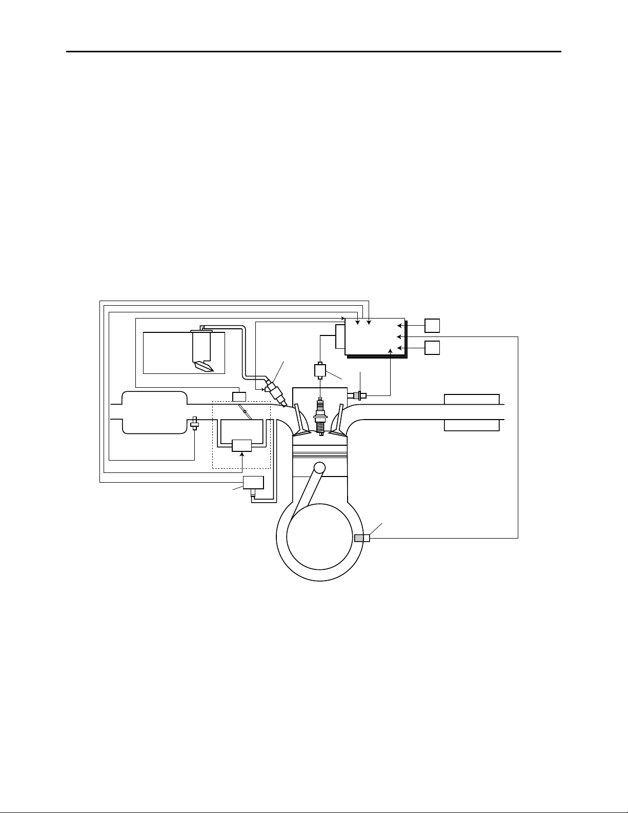
FI SYSTEM
The fuel pump delivers fuel to the fuel injector via the fuel filter. The pressure regulator maintains the
fuel pressure that is applied to the fuel injector at only 324 kPa (3.24 kgf/cm², 46.1 psi). Accordingly,
when the energizing signal from the ECU energizes the fuel injector, the fuel passage opens, causing
the fuel to be injected into the intake manifold only during the time the passage remains open. Therefore, the longer the length of time the fuel injector is energized (injection duration), the greater the volume of fuel that is supplied. Conversely, the shorter the length of time the fuel injector is energized
(injection duration), the lesser the volume of fuel that is supplied.
The injection duration and the injection timing are controlled by the ECU. Signals that are input from the
throttle position sensor, crankshaft position sensor, intake air pressure sensor, intake air temperature
sensor, coolant temperature sensor, lean angle sensor and speed sensor enable the ECU to determine
the injection duration. The injection timing is determined through the signals from the crankshaft position sensor. As a result, the volume of fuel that is required by the engine can be supplied at all times in
accordance with the driving conditions.
Illustration is for reference only.
1
14
B
13
1. Fuel pump
2. Fuel injector
3. Ignition coil
4. ECU (engine control unit)
5. Speed sensor
6. Lean angle sensor
7. Coolant temperature sensor
8. Crankshaft position sensor
9. Intake air pressure sensor
10.Throttle body
11.ISC (idle speed control) unit
12.Throttle position sensor
12
11
C
5
4
6
2
A
7
3
10
9
8
13.Intake air temperature sensor
14.Air filter case
A. Fuel system
B. Air system
C. Control system
1-3
Page 13

FEATURES
1-4
Page 14
FEATURES
EAS28P1033
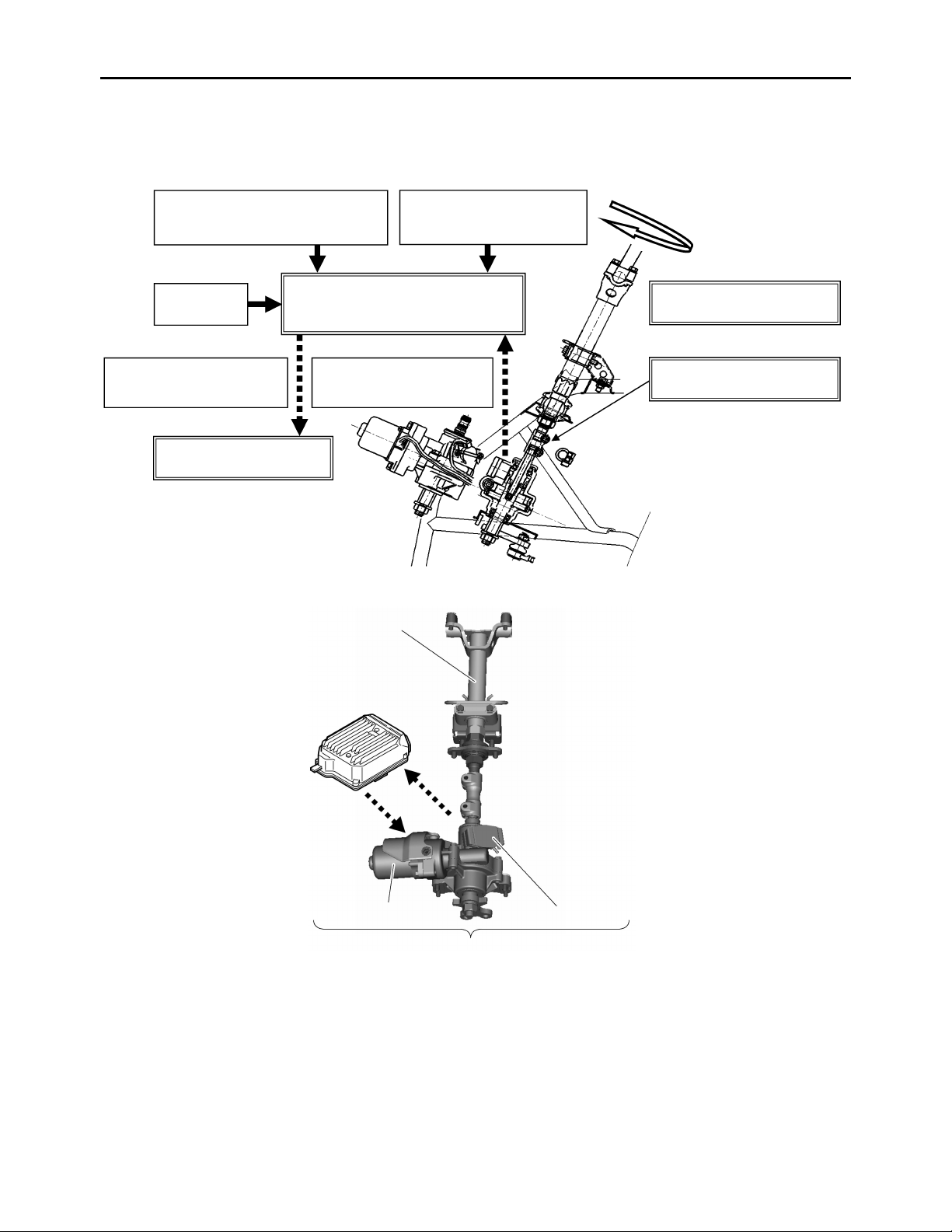
OUTLINE OF THE EPS (ELECTRIC POWER STEERING) SYSTEM (YFM5FGP/YFM7FGP only)
12
3 d a
e
f
5
c
4
b
6
8
7
1-5
Page 15

FEATURES
1. Speed information from speed sensor
2. Engine starting RPM information from ECU
3. Battery
4. Steering stem
5. EPS control unit
6. EPS motor
7. Torque sensor
8. EPS unit
a. Operates steering
ECA28P1027
NOTICE
b. Twists torsion bar
c. Sends the torque sensor signal
d. EPS control unit calculates assist power
e. Electricity output switched by EPS control unit
f. Activates EPS motor
To prevent accidental damage to the EPS unit, it must not be disassembled.
1-6
Page 16
FEATURES
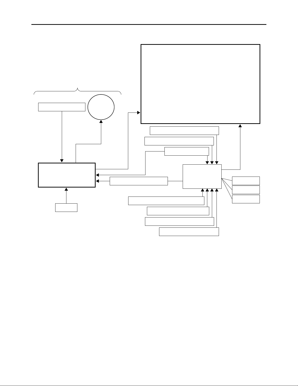
EAS28P1034
EPS (ELECTRIC POWER STEERING) SYSTEM BLOCK DIAGRAM (YFM5FGP/YFM7FGP only)
1
2
4
5
3
7
8
9
6
11
12
13
18
10
17
16
15
14
1-7
Page 17

1. EPS unit
2. Torque sensor
3. EPS motor
4. EPS control unit
5. Battery
6. Engine rpm signal
7. Coolant temperature sensor signal
8. Crankshaft position sensor signal
9. Speed sensor signal
10.ECU (engine control unit)
11.Intake air temperature sensor signal
12.Throttle position sensor signal
13.Intake air pressure sensor signal
14.Lean angle sensor signal
15.Ignition coil
16.Fuel pump
17.Fuel injector
18.Meter assembly
• Multifunction display:
Speedometer/Odometer/Tripmeter A/Trip
meter B/Clock/Fuel meter/Gear position
• Indicator and warning lights: EPS
warning/Engine trouble warning/Coolant
temperature warning/Reverse
indicator/Neutral indicator/Park
indicator/High-range indicator/Low-range
indicator/Differential lock
• FI and EPS self-diagnostic fault codes
FEATURES
1-8
Page 18

FEATURES
T
T
EAS28P1035
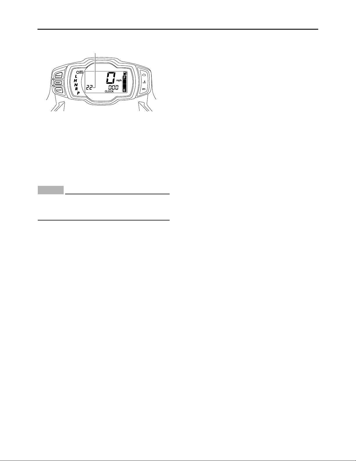
INSTRUMENT FUNCTIONS
Multifunction display
45
3
2
1
67
1. “CLOCK” button
2. “RESET” button
3. “SELECT” button
4. Speedometer
5. Fuel meter
6. Clock/Hour meter
7. Odometer/Tripmeter A/Tripmeter B
The multifunction display is equipped with the
following:
• a speedometer (which shows the riding speed)
• an odometer (which shows the total distance
traveled)
• two tripmeters (which show the distance traveled since they were last set to zero)
• a clock
• an hour meter (which shows the total time the
engine has been running)
• a fuel meter
• a self-diagnosis device
Odometer and tripmeter modes
Pushing the “SELECT” button switches the display between the odometer mode “ODO” and
the tripmeter modes “A” and “B” in the following
order:
ODO → TRIP A → TRIP B → ODO
To reset a tripmeter, select it by pushing the “SE-
LECT” button, and then push the “RESET” but-
ton for at least three seconds. The tripmeters
can be used to estimate the distance that can be
traveled with a full tank of fuel. This information
will enable you to plan future fuel stops.
IP
Pushing and holding in the “SELECT” button,
and turning the key to “ON” while the button is
pushed, switches the display between “mph”
and “km/h”.
Clock mode
Pushing the “CLOCK” button switches the display between the clock mode “CLOCK” and the
hour meter mode “HOUR” in the following order:
CLOCK → HOUR → CLOCK
To set the clock:
1. Set the display to the clock mode.
2. Push the “SELECT” button and “RESET” but-
ton together for at least three seconds.
3. When the hour digits start flashing, push the
“RESET” button to set the hours.
4. Push the “SELECT” button, and the minute
digits will start flashing.
5. Push the “RESET” button to set the minutes.
6. Push the “SELECT” button and then release
it to start the clock.
Fuel meter
1
2
3
1. Fuel level warning indicator
2. Fuel meter
3. “E” segment
The fuel meter indicates the amount of fuel in the
fuel tank. The display segments of the fuel meter
disappear from “F” (full) towards “E” (empty) as
the fuel level decreases. When the “E” segment
disappears and the fuel level warning indicator
flashes, refuel as soon as possible.
IP
This fuel meter is equipped with a self-diagnosis
system. If the electrical circuit is defective, all the
display segments and fuel level warning indicator will start flashing. If this occurs, check the
electrical circuit.
Refer to “SIGNALING SYSTEM” on page 9-19.
1-9
Page 19
Self-diagnosis device
1
1. Fault code display
This model is equipped with a self-diagnosis device for various electrical circuits.
If any of those circuits are defective, the multifunction display will indicate a two-digit fault
code. If the multifunction display indicates such
a fault code, note the code number, and check
the vehicle.
ECA28P1028
NOTICE
If the multifunction display indicates a fault
code, the vehicle should be checked as soon
as possible in order to avoid engine damage.
FEATURES
1-10
Page 20
EAS20180
IMPORTANT INFORMATION
EAS20190
PREPARATION FOR REMOVAL AND
DISASSEMBLY
1. Before removal and disassembly, remove all
dirt, mud, dust and foreign material.
2. Use only the proper tools and cleaning equipment.
Refer to “SPECIAL TOOLS” on page 1-14.
3. When disassembling, always keep mated
parts together. This includes gears, cylinders,
pistons and other parts that have been “mated” through normal wear. Mated parts must
always be reused or replaced as an assembly.
IMPORTANT INFORMATION
EAS20210
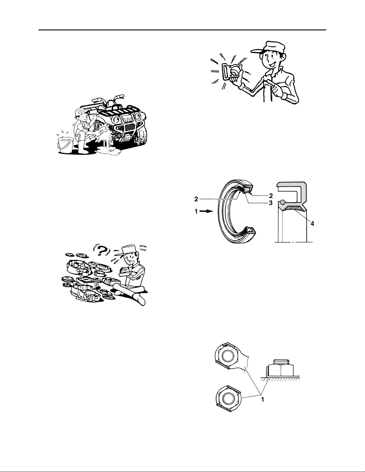
GASKETS, OIL SEALS AND O-RINGS
1. When overhauling the engine, replace all
gaskets, seals and O-rings. All gasket surfaces, oil seal lips and O-rings must be cleaned.
2. During reassembly, properly oil all mating
parts and bearings and lubricate the oil seal
lips with grease.
4. During disassembly, clean all of the parts and
place them in trays in the order of disassembly. This will speed up assembly and allow for
the correct installation of all parts.
5. Keep all parts away from any source of fire.
EAS20200
REPLACEMENT PARTS
Use only genuine Yamaha parts for all replacements. Use oil and grease recommended by
Yamaha for all lubrication jobs. Other brands
may be similar in function and appearance, but
inferior in quality.
1. Oil
2. Lip
3. Spring
4. Grease
EAS20220
LOCK WASHERS/PLATES AND COTTER
PINS
After removal, replace all lock washers/plates
“1” and cotter pins. After the bolt or nut has been
tightened to specification, bend the lock tabs
along a flat of the bolt or nut.
1-11
Page 21

EAS20230
BEARINGS AND OIL SEALS
Install bearings “1” and oil seals “2” so that the
manufacturer marks or numbers are visible.
When installing oil seals “2”, lubricate the oil seal
lips with a light coat of lithium-soap-based
grease. Oil bearings liberally when installing, if
appropriate.
ECA13300
NOTICE
Do not spin the bearing with compressed air
because this will damage the bearing surfaces.
IMPORTANT INFORMATION
EAS20240
CIRCLIPS
Before reassembly, check all circlips carefully
and replace damaged or distorted circlips. Always replace piston pin clips after one use.
When installing a circlip “1”, make sure the
sharp-edged corner “2” is positioned opposite
the thrust “3” that the circlip receives.
1-12
Page 22

EAS20250
T
T
T
CHECKING THE CONNECTIONS
Check the leads, couplers, and connectors for
stains, rust, moisture, etc.
1. Disconnect:
• Lead
• Coupler
• Connector
2. Check:
• Lead
• Coupler
• Connector
Moisture → Dry with an air blower.
Rust/stains → Connect and disconnect sev-
eral times.
CHECKING THE CONNECTIONS
Pocket tester
90890-03112
IP
• If there is no continuity, clean the terminals.
• When checking the wire harness, perform
steps (1) to (3).
• As a quick remedy, use a contact revitalizer
available at most part stores.
Analog pocket tester
YU-03112-C
3. Check:
• All connections
Loose connection → Connect properly.
IP
If the pin “1” on the terminal is flattened, bend it
up.
4. Connect:
• Lead
• Coupler
• Connector
IP
Make sure all connections are tight.
5. Check:
• Continuity
(with the pocket tester)
1-13
Page 23

SPECIAL TOOLS
T
EAS20260
SPECIAL TOOLS
The following special tools are necessary for complete and accurate tune-up and assembly. Use only
the appropriate special tools as this will help prevent damage caused by the use of inappropriate tools
or improvised techniques. Special tools, part numbers or both may differ depending on the country.
When placing an order, refer to the list provided below to avoid any mistakes.
IP
• For U.S.A. and Canada, use part numbers starting with “YM-”, “YU-”, or “ACC-”.
• For others, use part numbers starting with “90890-”.
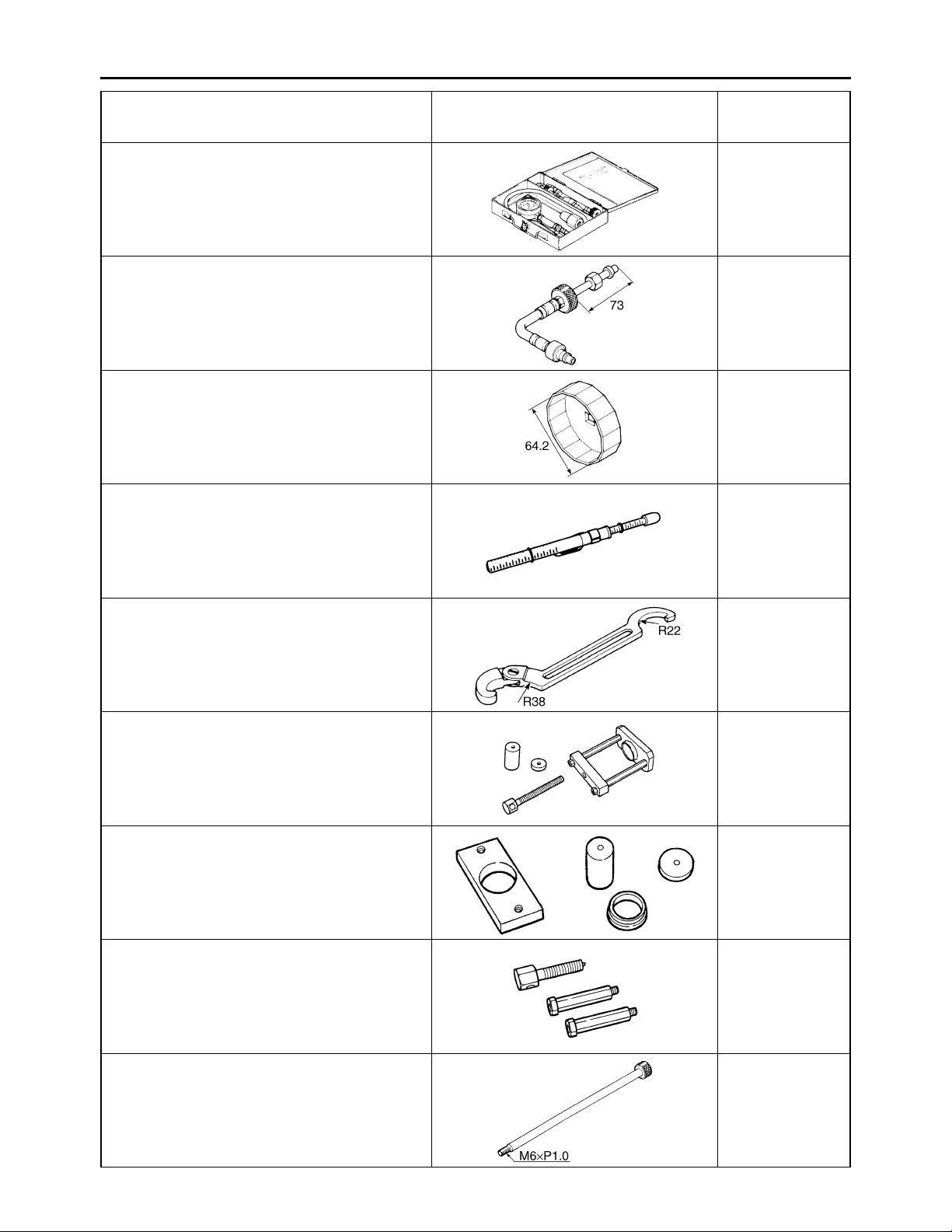
Tool name/Tool No. Illustration
Pocket tester
90890-03112
Analog pocket tester
YU-03112-C
Thickness gauge
90890-03079
Narrow gauge set
YM-34483
Tappet adjusting tool
90890-01311
Six piece tappet set
YM-A5970
Reference
pages
1-13, 9-81,
9-82, 9-83,
9-87, 9-89,
9-90, 9-91,
9-92, 9-93,
9-94, 9-95,
9-96, 9-97,
9-98
3-5
3-5
YM-A5970
ø9ø8 ø10
ø3 ø4
Digital tachometer
3-8
90890-06760
YU-39951-B
Timing light
3-8
90890-03141
Inductive clamp timing light
YU-03141
1-14
Page 24
SPECIAL TOOLS
Tool name/Tool No. Illustration
Compression gauge
90890-03081
Engine compression tester
YU-33223
Extension
90890-04082
Oil filter wrench
90890-01426
YU-38411
Belt tension gauge
90890-03170
Rear drive belt tension gauge
YM-03170
Reference
pages
3-9
3-9
3-11
3-28
Ring nut wrench
90890-01268
Spanner wrench
YU-01268
Ball joint remover
90890-01474
YM-01474
Ball joint remover attachment set
90890-01480
Ball joint adapter set
YM-01480
Ball joint remover short shaft set
90890-01514
YM-01514
3-31, 3-32
4-57, 4-61
4-57, 4-61
4-57
Slide hammer bolt
90890-01083
Slide hammer bolt 6 mm
YU-01083-1
5-18, 5-20
1-15
Page 25
SPECIAL TOOLS
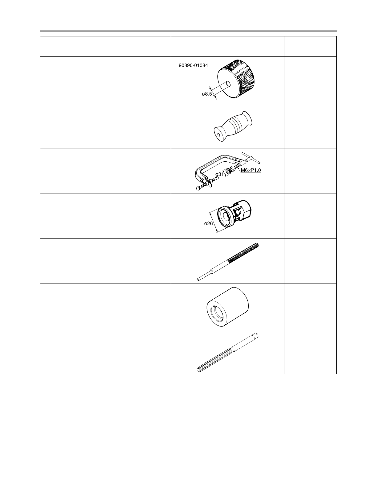
Tool name/Tool No. Illustration
Weight
90890-01084
YU-01083-3
Valve spring compressor
90890-04019
YM-04019
Valve spring compressor attachment
90890-01243
Valve spring compressor adapter (26 mm)
YM-01253-1
Reference
pages
5-18
YU-01083-3
5-22, 5-27
5-22, 5-27
Valve guide remover (ø6)
90890-04064
Valve guide remover (6.0 mm)
YM-04064-A
Valve guide installer (ø6)
90890-04065
Valve guide installer (6.0 mm)
YM-04065-A
Valve guide reamer (ø6)
90890-04066
Valve guide reamer (6.0 mm)
YM-04066
5-23
5-23
5-23
1-16
Page 26
SPECIAL TOOLS
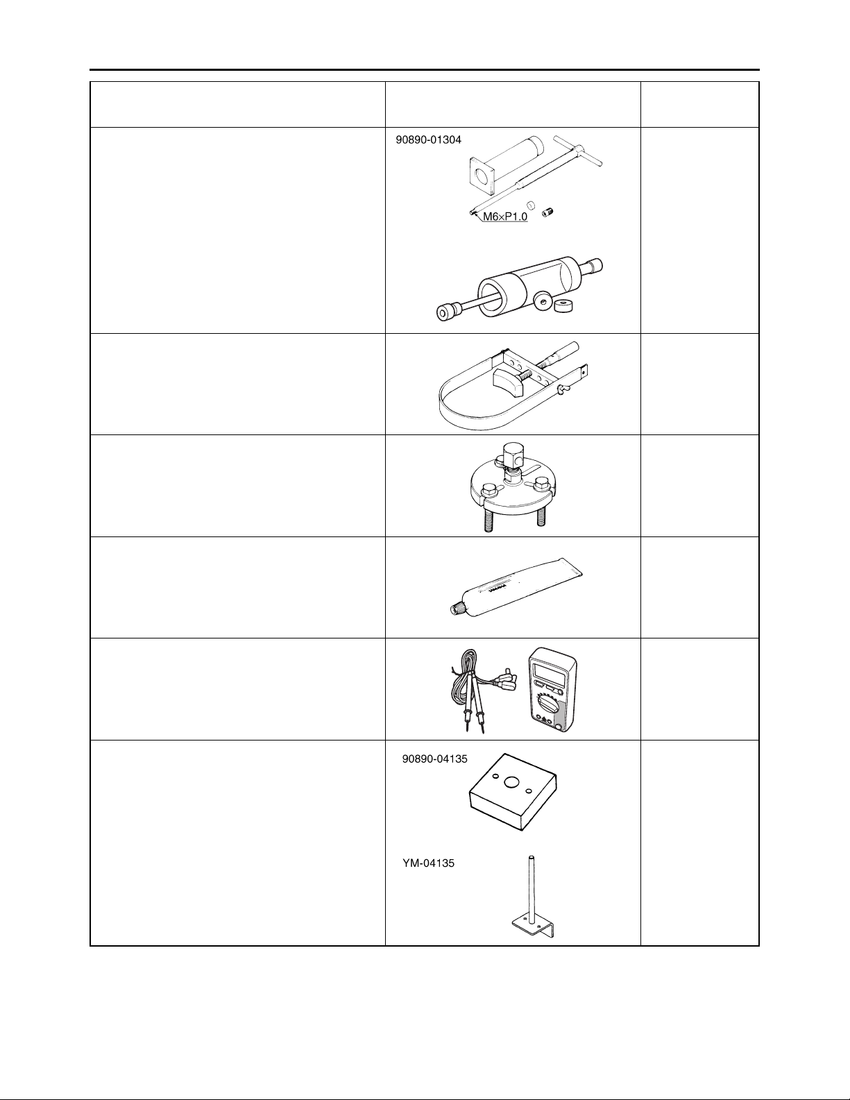
Tool name/Tool No. Illustration
Piston pin puller set
90890-01304
Piston pin puller
YU-01304
Sheave holder
90890-01701
Primary clutch holder
YS-01880-A
Flywheel puller
90890-01362
Heavy duty puller
YU-33270-B
Reference
pages
5-29
YU-01304
5-36, 5-37,
5-38, 5-50,
5-54
5-36
Yamaha bond No. 1215
90890-85505
(Three Bond No.1215®)
Digital circuit tester
90890-03174
Model 88 Multimeter with tachometer
YU-A1927
Sheave fixed block
90890-04135
Sheave fixed bracket
YM-04135
5-38, 5-66
5-42, 7-7
5-50, 5-53
1-17
Page 27

SPECIAL TOOLS
Tool name/Tool No. Illustration
Locknut wrench
90890-01348
YM-01348
Sheave spring compressor
90890-04134
YM-04134
Reference
pages
5-50, 5-53
5-50, 5-53
Universal clutch holder
90890-04086
YM-91042
Crankcase separating tool
90890-01135
Crankcase separator
YU-01135-B
5-58, 5-59
5-70
1-18
Page 28
SPECIAL TOOLS
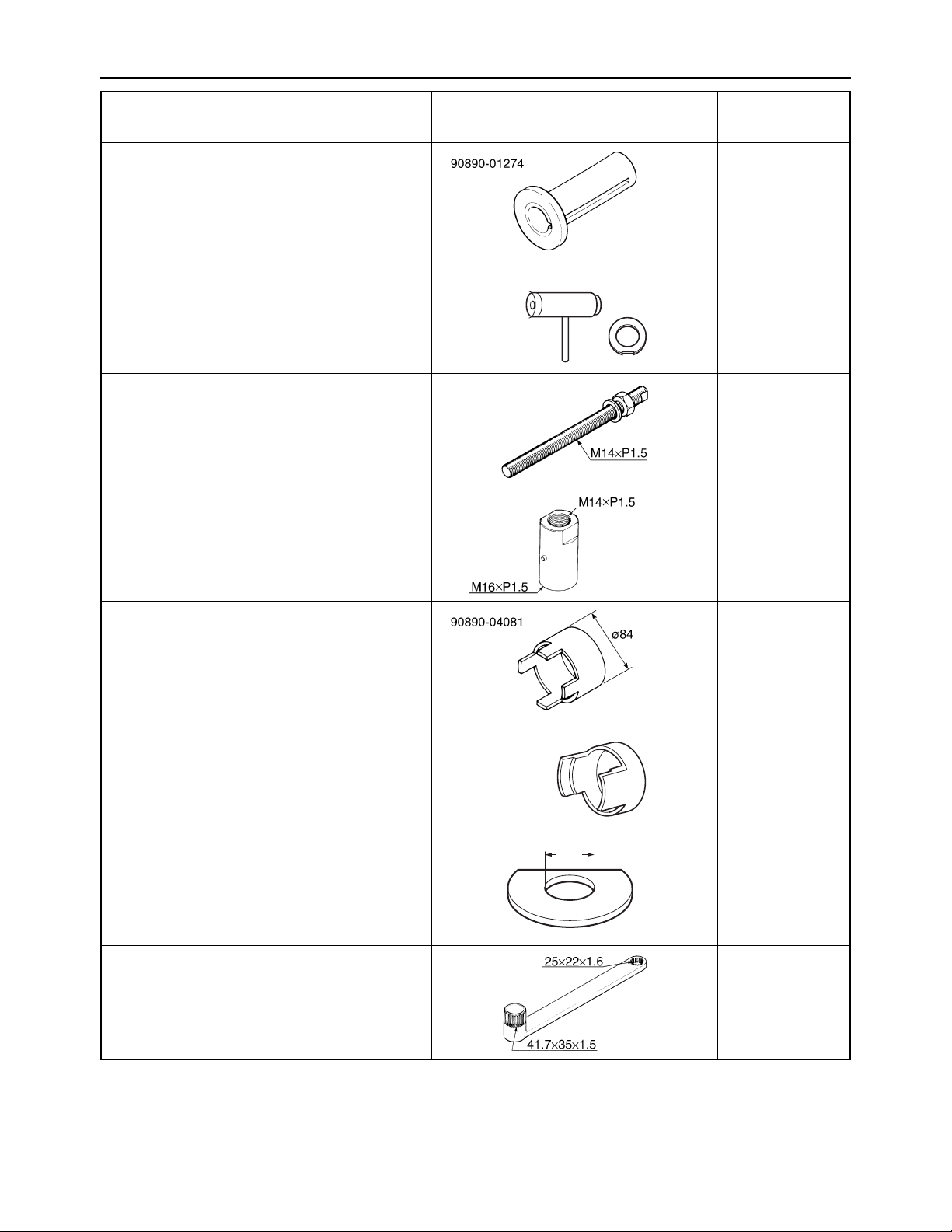
Tool name/Tool No. Illustration
Crankshaft installer pot
90890-01274
Installing pot
YU-90058
Crankshaft installer bolt
90890-01275
Bolt
YU-90060
Adapter (M16)
90890-04130
Adapter #13
YM-04059
Reference
pages
5-72
YU-90058/YU-90059
5-72
5-72
Spacer (crankshaft installer)
90890-04081
Pot spacer
YM-91044
Spacer
90890-01309
Pot spacer
YU-90059
Coupling gear/middle shaft tool
90890-01229
Gear holder
YM-01229
YM-91044
ø35
5-72
5-72
5-82, 5-85
1-19
Page 29

SPECIAL TOOLS
Tool name/Tool No. Illustration
Bearing retainer wrench
90890-04128
Middle gear bearing retainer
YM-04128
Ring nut wrench
90890-01430
YM-38404
Final gear backlash band
90890-01511
Middle drive gear lash tool
YM-01230
Radiator cap tester
90890-01325
Radiator pressure tester
YU-24460-01
Reference
pages
5-83, 5-84
5-83, 5-84
5-86, 8-29
6-3
Radiator cap tester adapter
90890-01352
Radiator pressure tester adapter
YU-33984
Mechanical seal installer
90890-04132
Water pump seal installer
YM-33221-A
YU-24460-01
6-3
YU-33984
6-9
1-20
Page 30

SPECIAL TOOLS
Tool name/Tool No. Illustration
Middle driven shaft bearing driver
90890-04058
Bearing driver 40 mm
YM-04058
Pressure gauge
90890-03153
YU-03153
Fuel pressure adapter
90890-03176
YM-03176
Boots band installation tool
90890-01526
YM-01526
Reference
pages
6-9
7-7
7-7
8-9, 8-11, 8-22,
8-24
Ring gear fix bolt (M10)
90890-01527
YM-01527
Gear lash measurement tool
90890-01475
Middle drive gear lash tool
YM-01475
Ring gear fix bolt (M14)
90890-01524
YM-01524
Ignition checker
90890-06754
Opama pet-4000 spark checker
YM-34487
8-13
M10×P1.25
8-13
8-29
M14×P1.5
9-91
1-21
Page 31

SPECIFICATIONS
GENERAL SPECIFICATIONS ........................................................................2-1
ENGINE SPECIFICATIONS ............................................................................ 2-2
CHASSIS SPECIFICATIONS ........................................................................2-10
ELECTRICAL SPECIFICATIONS ................................................................. 2-13
TIGHTENING TORQUES .............................................................................. 2-16
GENERAL TIGHTENING TORQUE SPECIFICATIONS......................... 2-16
ENGINE TIGHTENING TORQUES.........................................................2-17
CHASSIS TIGHTENING TORQUES....................................................... 2-20
LUBRICATION POINTS AND LUBRICANT TYPES ....................................2-24
ENGINE...................................................................................................2-24
LUBRICATION SYSTEM CHART AND DIAGRAMS.................................... 2-27
LUBRICATION DIAGRAMS ....................................................................2-27
COOLING SYSTEM DIAGRAMS ..................................................................2-31
CABLE ROUTING ......................................................................................... 2-33
2
Page 32

GENERAL SPECIFICATIONS
EAS29110
GENERAL SPECIFICATIONS
Model
Model 28P1, 28P5 (YFM5FGY)
34D1, 34D5, 34D8 (YFM5FGPY)
5C0A, 5C0C (YFM7FGY)
43P1, 43P5, 43P8, 43PA (YFM7FGPY)
Dimensions
Overall length 2065 mm (81.3 in)
Overall width 1180 mm (46.5 in)
Overall height 1240 mm (48.8 in)
Seat height 905 mm (35.6 in)
Wheelbase 1250 mm (49.2 in)
Ground clearance 275 mm (10.8 in)
Minimum turning radius 3200 mm (126 in)
Weight
With oil and fuel 294.0 kg (648 lb)
Maximum loading limit 220.0 kg (485 lb)
(Total weight of rider, cargo, accessories, and
tongue)
2-1
Page 33

ENGINE SPECIFICATIONS
EAS29120
ENGINE SPECIFICATIONS
Engine
Engine type Liquid cooled 4-stroke, SOHC
Displacement 558.0 cm³ (YFM5FGY/YFM5FGPY)
686.0 cm³ (YFM7FGY/YFM7FGPY)
Cylinder arrangement Forward-inclined single cylinder
Bore × stroke 92.0 × 84.0 mm (3.62 × 3.31 in)
(YFM5FGY/YFM5FGPY)
102.0 × 84.0 mm (4.02 × 3.31 in)
(YFM7FGY/YFM7FGPY)
Compression ratio 9.30 :1 (YFM5FGY/YFM5FGPY)
9.20 :1 (YFM7FGY/YFM7FGPY)
Standard compression pressure (at sea level) 480 kPa (4.8 kgf/cm², 68.3 psi)
(YFM5FGY/YFM5FGPY)
450 kPa (4.5 kgf/cm², 64.0 psi)
(YFM7FGY/YFM7FGPY)
Minimum–maximum 420–540 kPa (4.2–5.4 kgf/cm², 59.7–76.8 psi)
(YFM5FGY/YFM5FGPY)
390–500 kPa (3.9–5.0 kgf/cm², 55.5–71.1 psi)
(YFM7FGY/YFM7FGPY)
Starting system Electric starter
Fuel
Recommended fuel Unleaded gasoline only
Fuel tank capacity 20.0 L (5.28 US gal, 4.40 Imp.gal)
Fuel reserve amount 4.5 L (1.19 US gal, 0.99 Imp.gal)
Engine oil
Lubrication system Wet sump
Type YAMALUBE 4 5W-30 or 10W-40 or 20W-50,
SAE 5W-30 or SAE 10W-40 or SAE 20W-50
Recommended engine oil grade API service SG type or higher, JASO standard
MA
Engine oil quantity
Total amount 2.40 L (2.54 US qt, 2.11 Imp.qt)
Without oil filter cartridge replacement 2.00 L (2.11 US qt, 1.76 Imp.qt)
With oil filter cartridge replacement 2.10 L (2.22 US qt, 1.85 Imp.qt)
Oil pressure (hot) 50.0 kPa/1600 r/min (0.50 kgf/cm²/1600 r/min,
7.3 psi/1600 r/min)
Final gear oil
Type SAE 80 API GL-4 Hypoid gear oil
Total amount 0.25 L (0.26 US qt, 0.22 Imp.qt)
Periodic oil change 0.20 L (0.21 US qt, 0.18 Imp.qt)
Differential gear oil
Type SAE 80 API GL-4 Hypoid gear oil
Total amount 0.23 L (0.24 US qt, 0.20 Imp.qt)
Periodic oil change 0.22 L (0.23 US qt, 0.19 Imp.qt)
2-2
Page 34

ENGINE SPECIFICATIONS
Oil filter
Oil filter type Cartridge (paper)
Oil pump
Oil pump type Trochoid
Inner-rotor-to-outer-rotor-tip clearance Less than 0.12 mm (0.0047 in)
Limit 0.20 mm (0.0079 in)
Outer-rotor-to-oil-pump-housing clearance 0.090–0.170 mm (0.0035–0.0067 in)
Limit 0.24 mm (0.0094 in)
Oil-pump-housing-to-inner-and-outer-rotor
clearance 0.03–0.10 mm (0.0012–0.0039 in)
Limit 0.17 mm (0.0067 in)
Pressure check location Cylinder head
Cooling system
Radiator capacity (including all routes) 1.99 L (2.10 US qt, 1.75 Imp.qt)
Coolant reservoir capacity (up to the maximum level
mark) 0.24 L (0.25 US qt, 0.21 Imp.qt)
From low to full level 0.14 L (0.15 US qt, 0.12 Imp.qt)
Radiator cap opening pressure 93.3–122.7 kPa (0.95–1.25 kgf/cm², 13.5–17.8
psi)
Valve relief pressure 4.9 kPa (0.05 kgf/cm², 0.7 psi)
Thermostat
Model/manufacturer 3B4/NIPPON THERMOSTAT
Valve opening temperature 50–54 °C (122–129 °F)
Valve full open temperature 70 °C (158 °F)
Valve lift (full open) 7.0 mm (0.28 in)
Radiator core
Width 248.2 mm (9.77 in)
Height 340 mm (13.4 in)
Depth 22 mm (0.87 in)
Water pump
Water pump type Single suction centrifugal pump
Reduction ratio 32/31 (1.032)
Impeller shaft tilt limit 0.15 mm (0.006 in)
Spark plug
Manufacturer/model NGK/LMAR6A-9
Spark plug gap 0.8–0.9 mm (0.031–0.035 in)
Cylinder head
Volume 51.40–54.40 cm³ (YFM5FGY/YFM5FGPY)
56.70–60.30 cm³ (YFM7FGY/YFM7FGPY)
Warpage limit 0.03 mm (0.0012 in)
Camshaft
Drive system Chain drive (left)
2-3
Page 35

ENGINE SPECIFICATIONS
Camshaft lobe dimensions
Intake A 43.488–43.588 mm (1.7121–1.7161 in)
Limit 43.388 mm (1.7082 in)
Intake B 36.959–37.059 mm (1.4551–1.4590 in)
Limit 36.859 mm (1.4511 in)
Exhaust A 43.129–43.229 mm (1.6980–1.7019 in)
Limit 43.029 mm (1.6941 in)
Exhaust B 37.007–37.107 mm (1.4570–1.4609 in)
Limit 36.907 mm (1.4530 in)
A
B
Camshaft runout limit 0.015 mm (0.0006 in)
Timing chain
Model/number of links 98XRH2010/126
Tensioning system Automatic
Rocker arm/rocker arm shaft
Rocker arm inside diameter 12.000–12.018 mm (0.4724–0.4731 in)
Rocker arm shaft outside diameter 11.981–11.991 mm (0.4717–0.4721 in)
Rocker-arm-to-rocker-arm-shaft clearance 0.009–0.037 mm (0.0004–0.0015 in)
Valve, valve seat, valve guide
Valve clearance (cold)
Intake 0.09–0.13 mm (0.0035–0.0051 in)
Exhaust 0.16–0.20 mm (0.0063–0.0079 in)
Valve dimensions
Valve head diameter A (intake) 32.90–33.10 mm (1.2953–1.3031 in)
(YFM5FGY/YFM5FGPY)
37.90–38.10 mm (1.4921–1.5000 in)
(YFM7FGY/YFM7FGPY)
Valve head diameter A (exhaust) 27.90–28.10 mm (1.0984–1.1063 in)
(YFM5FGY/YFM5FGPY)
31.90–32.10 mm (1.2559–1.2638 in)
(YFM7FGY/YFM7FGPY)
A
Valve face width B (intake) 2.26 mm (0.0890 in)
2-4
Page 36

ENGINE SPECIFICATIONS
Valve face width B (exhaust) 2.26 mm (0.0890 in)
B
Valve seat width C (intake) 1.00–1.20 mm (0.0394–0.0472 in)
Limit 1.60 mm (0.0630 in)
Valve seat width C (exhaust) 1.00–1.20 mm (0.0394–0.0472 in)
Limit 1.60 mm (0.0630 in)
C
Valve margin thickness D (intake) 0.80–1.20 mm (0.0315–0.0472 in)
Limit 0.4 mm (0.02 in)
Valve margin thickness D (exhaust) 0.80–1.20 mm (0.0315–0.0472 in)
Limit 0.4 mm (0.02 in)
D
Valve stem diameter (intake) 5.975–5.990 mm (0.2352–0.2358 in)
Limit 5.945 mm (0.2341 in)
Valve stem diameter (exhaust) 5.960–5.975 mm (0.2346–0.2352 in)
Limit 5.930 mm (0.2335 in)
Valve guide inside diameter (intake) 6.000–6.012 mm (0.2362–0.2367 in)
Limit 6.050 mm (0.2382 in)
Valve guide inside diameter (exhaust) 6.000–6.012 mm (0.2362–0.2367 in)
Limit 6.050 mm (0.2382 in)
Valve-stem-to-valve-guide clearance (intake) 0.010–0.037 mm (0.0004–0.0015 in)
Limit 0.080 mm (0.0031 in)
Valve-stem-to-valve-guide clearance (exhaust) 0.025–0.052 mm (0.0010–0.0020 in)
Limit 0.100 mm (0.0039 in)
Valve stem runout 0.040 mm (0.0016 in)
Cylinder head valve seat width (intake) 1.00–1.20 mm (0.0394–0.0472 in)
Cylinder head valve seat width (exhaust) 1.00–1.20 mm (0.0394–0.0472 in)
Valve spring
Free length (intake) 40.38 mm (1.59 in)
Limit 38.36 mm (1.51 in)
Free length (exhaust) 40.38 mm (1.59 in)
Limit 38.36 mm (1.51 in)
Installed length (intake) 35.00 mm (1.38 in)
Installed length (exhaust) 35.00 mm (1.38 in)
2-5
Page 37

ENGINE SPECIFICATIONS
Spring rate K1 (intake) 34.18 N/mm (3.49 kgf, 195.16 lbf)
Spring rate K2 (intake) 44.14 N/mm (4.50 kgf, 252.04 lbf)
Spring rate K1 (exhaust) 34.18 N/mm (3.49 kgf, 195.16 lbf)
Spring rate K2 (exhaust) 44.14 N/mm (4.50 kgf, 252.04 lbf)
Installed compression spring force (intake) 171.00–197.00 N (17.44–20.09 kgf, 38.44–
44.29 lbf)
Installed compression spring force (exhaust) 171.00–197.00 N (17.44–20.09 kgf, 38.44–
44.29 lbf)
Spring tilt (intake) 2.5°/1.80 mm
Spring tilt (exhaust) 2.5°/1.80 mm
Winding direction (intake) Clockwise
Winding direction (exhaust) Clockwise
Cylinder
Bore 92.000–92.010 mm (3.6220–3.6224 in)
(YFM5FGY/YFM5FGPY)
102.000–102.010 mm (4.0157–4.0161 in)
(YFM7FGY/YFM7FGPY)
Wear limit 92.080 mm (3.6252 in)
(YFM5FGY/YFM5FGPY)
102.080 mm (4.0189 in)
(YFM7FGY/YFM7FGPY)
Taper limit 0.05 mm (0.002 in)
Out of round limit 0.05 mm (0.002 in)
Piston
Piston-to-cylinder clearance 0.030–0.055 mm (0.0012–0.0022 in)
Limit 0.10 mm (0.0039 in) (YFM5FGY/YFM5FGPY)
0.13 mm (0.0051 in) (YFM7FGY/YFM7FGPY)
Diameter D 91.955–91.970 mm (3.6203–3.6209 in)
(YFM5FGY/YFM5FGPY)
101.955–101.970 mm (4.0140–4.0146 in)
(YFM7FGY/YFM7FGPY)
Height H 10.0 mm (0.39 in)
H
D
Offset 0.50 mm (0.0197 in)
Offset direction Intake side
Piston pin bore inside diameter 23.004–23.015 mm (0.9057–0.9061 in)
Limit 23.045 mm (0.9073 in)
Piston pin outside diameter 22.991–23.000 mm (0.9052–0.9055 in)
2-6
Page 38

ENGINE SPECIFICATIONS
Limit 22.971 mm (0.9044 in)
Piston-pin-to-piston-pin-bore clearance 0.004–0.024 mm (0.0002–0.0009 in)
Limit 0.0740 mm (0.0029 in)
Piston ring
Top ring
Ring type Barrel
Dimensions (B × T) 1.20 × 3.50 mm (0.05 × 0.14 in)
(YFM5FGY/YFM5FGPY)
1.20 × 3.80 mm (0.05 × 0.15 in)
(YFM7FGY/YFM7FGPY)
B
T
End gap (installed) 0.20–0.35 mm (0.008–0.014 in)
Limit 0.60 mm (0.024 in)
Ring side clearance 0.030–0.070 mm (0.0012–0.0028 in)
Limit 0.12 mm (0.0047 in)
2nd ring
Ring type Taper
Dimensions (B × T) 1.20 × 4.00 mm (0.05 × 0.16 in)
B
T
End gap (installed) 0.75–0.90 mm (0.03–0.04 in)
Limit 1.25 mm (0.049 in)
Ring side clearance 0.020–0.060 mm (0.0008–0.0024 in)
(YFM5FGY/YFM5FGPY)
0.030–0.070 mm (0.0012–0.0028 in)
(YFM7FGY/YFM7FGPY)
Limit 0.12 mm (0.0047 in) (YFM5FGY/YFM5FGPY)
0.13 mm (0.0051 in) (YFM7FGY/YFM7FGPY)
Oil ring
Dimensions (B × T) 2.00 × 2.80 mm (0.08 × 0.11 in)
(YFM5FGY/YFM5FGPY)
2.50 × 2.80 mm (0.10 × 0.11 in)
(YFM7FGY/YFM7FGPY)
B
T
End gap (installed) 0.20–0.70 mm (0.01–0.03 in)
Ring side clearance 0.04–0.13 mm (0.0016–0.0051 in)
(YFM5FGY/YFM5FGPY)
0.060–0.150 mm (0.0024–0.0059 in)
(YFM7FGY/YFM7FGPY)
Crankshaft
Width A 74.95–75.00 mm (2.951–2.953 in)
2-7
Page 39

ENGINE SPECIFICATIONS
Runout limit C 0.030 mm (0.0012 in)
Big end side clearance D 0.350–0.650 mm (0.0138–0.0256 in)
CC
D
A
Balancer
Balancer drive method Gear
Automatic centrifugal clutch
Clutch type Wet, centrifugal automatic
Clutch shoe thickness 1.5 mm (0.06 in)
Limit 1.0 mm (0.04 in)
Clutch-in revolution 2000–2100 r/min (YFM5FGY/YFM5FGPY)
1950–2050 r/min (YFM7FGY/YFM7FGPY)
Clutch-stall revolution 3500–3600 r/min (YFM5FGY/YFM5FGPY)
3550–3650 r/min (YFM7FGY/YFM7FGPY)
V-belt
V-belt width 33.3 mm (1.31 in)
Limit 30.0 mm (1.18 in)
Transmission
Transmission type V-belt automatic
Primary reduction system V-belt
Secondary reduction system Shaft drive
Secondary reduction ratio 41/21 × 24/18 × 33/9 (9.544)
Operation Left hand operation
Single speed automatic 2.380–0.700 :1
Low range 31/16 (1.938)
High range 31/27 (1.148)
Reverse gear 23/14 × 28/23 (2.000)
Drive axle runout limit 0.06 mm (0.0024 in)
Shifting mechanism
Shift mechanism type Shift drum and guide bar
Shift fork-R, -L thickness 5.76–5.89 mm (0.227–0.232 in)
Decompression device
Device type Auto decomp
Air filter
Air filter element Wet element
Air filter oil grade Foam air filter oil
2-8
Page 40

ENGINE SPECIFICATIONS
Fuel pump
Pump type Electrical
Model/manufacturer 3B4/DENSO
Throttle body
Type/quantity 40EIS/1
Manufacturer MIKUNI
ID mark 28P1 00 (YFM5FGY/YFM5FGPY)
43P1 00 (YFM7FGY/YFM7FGPY)
Throttle valve size #50
Fuel injector
Model/quantity 297510–1010/1
Manufacturer DENSO
Idling condition
Engine idling speed 1550–1650 r/min
Intake vacuum 33.0 kPa (248 mmHg, 9.7 inHg)
(YFM5FGY/YFM5FGPY)
35.0 kPa (263 mmHg, 10.3 inHg)
(YFM7FGY/YFM7FGPY)
Water temperature 85.0–95.0 °C (185.0–203.0 °F)
(YFM5FGY/YFM5FGPY)
75.0–85.0 °C (167.0–185.0 °F)
(YFM7FGY/YFM7FGPY)
Oil temperature 80.0–90.0 °C (176.0–194.0 °F)
(YFM5FGY/YFM5FGPY)
55.0–65.0 °C (131.00–149.0 °F)
(YFM7FGY/YFM7FGPY)
Throttle lever free play 3.0–5.0 mm (0.12–0.20 in)
Speed limiter length Less than 12 mm (0.47 in)
Shaft drive
Middle gear backlash 0.10–0.30 mm (0.004–0.012 in)
Final gear backlash 0.10–0.20 mm (0.004–0.008 in)
Differential gear backlash 0.05–0.25 mm (0.002–0.010 in)
2-9
Page 41

CHASSIS SPECIFICATIONS
EAS29130
CHASSIS SPECIFICATIONS
Chassis
Frame type Steel tube frame
Caster angle 5.0°
Camber angle 0.0°
Kingpin angle 11.0°
Kingpin offset 0.0 mm (0.00 in)
Trail 26.0 mm (1.02 in)
Tread rear (STD) 915.0 mm (36.02 in)
Tread front (STD) 940.0 mm (37.01 in)
Toe-in (with tire touching the ground) 0.0–10.0 mm (0.00–0.39 in)
Front wheel
Wheel type Panel wheel
Rim size 12 × 6.0 AT
Rim material Steel (for models equipped with steel wheels)
Aluminum (for models equipped with aluminum
wheels)
Wheel travel 180 mm (7.1 in)
Radial wheel runout limit 2.0 mm (0.08 in)
Lateral wheel runout limit 2.0 mm (0.08 in)
Rear wheel
Wheel type Panel wheel
Rim size 12 × 7.5 AT
Rim material Steel (for models equipped with steel wheels)
Aluminum (for models equipped with aluminum
wheels)
Wheel travel 230 mm (9.1 in)
Radial wheel runout limit 2.0 mm (0.08 in)
Lateral wheel runout limit 2.0 mm (0.08 in)
Front tire
Type Tubeless
Size AT25 × 8–12
Manufacturer/model DUNLOP/KT421
Wear limit (front) 3 mm (0.12 in)
Rear tire
Type Tubeless
Size AT25 × 10–12
Manufacturer/model DUNLOP/KT425
Wear limit (rear) 3 mm (0.12 in)
Tire air pressure (measured on cold tires)
Recommended
Front 35 kPa (0.35 kgf/cm², 5.0 psi)
Rear 30 kPa (0.30 kgf/cm², 4.4 psi)
Minimum
Front 32 kPa (0.32 kgf/cm², 4.6 psi)
Rear 27 kPa (0.27 kgf/cm², 4.0 psi)
2-10
Page 42

CHASSIS SPECIFICATIONS
Front brake
Type Dual disc brake
Operation Right hand operation
Front brake lever free play (lever end) 0 mm (0 in)
Front disc brake
Disc outside diameter × thickness 220.0 × 3.5 mm (8.66 × 0.14 in)
Brake disc thickness limit 3.0 mm (0.12 in)
Brake disc deflection limit 0.1 mm (0.004 in)
Brake pad lining thickness (inner) 4.4 mm (0.17 in)
Limit 1.0 mm (0.04 in)
Brake pad lining thickness (outer) 4.4 mm (0.17 in)
Limit 1.0 mm (0.04 in)
Master cylinder inside diameter 12.70 mm (0.50 in)
Caliper cylinder inside diameter 33.96 mm (1.34 in)
Recommended fluid DOT 4
Rear brake
Type Dual disc brake
Operation Left hand and right foot operation
Rear brake lever free play (lever end) 0 mm (0 in)
Brake pedal free play 0.0–5.0 mm (0.00–0.20 in)
Rear disc brake
Disc outside diameter × thickness 205.0 × 3.5 mm (8.07 × 0.14 in)
Brake disc thickness limit 3.0 mm (0.12 in)
Brake disc deflection limit 0.1 mm (0.004 in)
Brake pad lining thickness (inner) 5.8 mm (0.23 in)
Limit 1.0 mm (0.04 in)
Brake pad lining thickness (outer) 5.8 mm (0.23 in)
Limit 1.0 mm (0.04 in)
Master cylinder inside diameter 12.70 mm (0.50 in)
Caliper cylinder inside diameter 33.96 mm (1.34 in)
Recommended fluid DOT 4
Steering
Steering bearing type Ball and race bearing
Steering tension 50 N (5.0 kgf) (YFM5FGPY/YFM7FGPY)
Front suspension
Type Double wishbone
Spring/shock absorber type Coil spring/oil damper
Wheel travel 180 mm (7.1 in)
Shock absorber travel 90.2 mm (3.55 in) (YFM5FGY/YFM5FGPY)
90.7 mm (3.57 in) (YFM7FGY/YFM7FGPY)
Spring free length 292.0 mm (11.50 in)
Installed length 233.1 mm (9.18 in) (YFM5FGY/YFM5FGPY)
233.5 mm (9.19 in) (YFM7FGY/YFM7FGPY)
Spring rate K1 23.00 N/mm (2.35 kgf/mm, 131.33 lb/in)
Spring stroke K1 0.0–90.2 mm (0.00–3.55 in)
(YFM5FGY/YFM5FGPY)
0.0–90.7 mm (0.00–3.57 in)
(YFM7FGY/YFM7FGPY)
Optional spring available No
2-11
Page 43

CHASSIS SPECIFICATIONS
Spring preload adjusting positions
Minimum 1
Standard 3
Maximum 5
Rear suspension
Type Double wishbone
Spring/shock absorber type Coil spring/oil damper
Wheel travel 230 mm (9.1 in)
Rear shock absorber assembly travel 109.2 mm (4.30 in)
Spring free length 318.1 mm (12.52 in) (YFM5FGY/YFM5FGPY)
314.5 mm (12.38 in) (YFM7FGY/YFM7FGPY)
Installed length 270.6 mm (10.65 in) (YFM5FGY/YFM5FGPY)
267.5 mm (10.53 in) (YFM7FGY/YFM7FGPY)
Spring rate K1 31.00 N/mm (3.16 kgf/mm, 177.01 lb/in)
(YFM5FGY/YFM5FGPY)
33.50 N/mm (3.42 kgf/mm, 191.29 lb/in)
(YFM7FGY/YFM7FGPY)
Spring rate K2 36.00 N/mm (3.67 kgf/mm, 205.56 lb/in)
(YFM7FGY/YFM7FGPY)
Spring stroke K1 0.0–109.2 mm (0.00–4.30 in)
(YFM5FGY/YFM5FGPY)
0.0–43.0 mm (0.00–1.69 in)
(YFM7FGY/YFM7FGPY)
Spring stroke K2 43.0–109.2 mm (1.69–4.30 in)
(YFM7FGY/YFM7FGPY)
Optional spring available No
Spring preload adjusting positions
Minimum 1
Standard 3
Maximum 5
2-12
Page 44

ELECTRICAL SPECIFICATIONS
EAS29140
ELECTRICAL SPECIFICATIONS
Voltage
System voltage 12 V
Ignition system
Ignition system TCI (digital)
Advancer type Digital
Ignition timing (B.T.D.C.) 5.0°/1600 r/min
Engine control unit
Model/manufacturer F8T83872/MITSUBISHI
(YFM5FGY/YFM5FGPY)
F8T83874/MITSUBISHI
(YFM7FGY/YFM7FGPY)
Fuel injection sensor
Crankshaft position sensor resistance 459–561 Ω at 20 °C (68 °F)
Intake air pressure sensor output voltage 3.75–4.25 V
Intake air temperature sensor resistance 290–390 Ω at 80 °C (176 °F)
Coolant temperature sensor resistance 2.45 kΩ at 20 °C (68 °F)
290–354 Ω at 80 °C (176 °F)
Ignition coil
Model/manufacturer 2JN/YAMAHA
Minimum ignition spark gap 6.0 mm (0.24 in)
Primary coil resistance 2.16–2.64 Ω at 20 °C (68 °F)
Secondary coil resistance 8.64–12.96 kΩ at 20 °C (68 °F)
Spark plug cap
Material Resin
Resistance 10.0 kΩ
AC magneto
Model/manufacturer F4T39373/MITSUBISHI
Standard output 14.0 V 34.0 A at 5,000 r/min
Stator coil resistance 0.108–0.132 Ω at 20 °C (68 °F)
Rectifier/regulator
Regulator type Semi conductor-short circuit
Model/manufacturer FH012AA/SHINDENGEN
Regulated voltage (DC) 14.2–14.8 V
Rectifier capacity (DC) 50.0 A
Withstand voltage 40.0 V
Battery
Model YTX20L-BS
Voltage, capacity 12 V, 18.0 Ah
Manufacturer GS YUASA
Ten hour rate amperage 1.8 A
2-13
Page 45

ELECTRICAL SPECIFICATIONS
Headlight
Bulb type Halogen bulb
Bulb voltage, wattage × quantity
Headlight 12 V, 35.0/35.0 W × 2
Tail/brake light 12 V, 5.0/21.0 W × 1
Meter lighting EL
Indicator and warning lights
Neutral indicator light LED
Reverse indicator light LED
Coolant temperature warning light LED
Park indicator light LED
On-Command four-wheel-drive/differential gear lock
indicator LCD
Engine trouble warning light LED
High-range indicator light LED
Low-range indicator light LED
Differential gear lock indicator light LED
EPS warning light LED (YFM5FGPY/YFM7FGPY)
Electric starting system
System type Constant mesh
Starter motor
Model/manufacturer SM-17/MITSUBA
Power output 0.80 kW
Armature coil resistance 0.0050–0.0150 Ω at 20 °C (68 °F)
Brush overall length 12.0 mm (0.47 in)
Limit 6.50 mm (0.26 in)
Brush spring force 6.02–6.51 N (614–664 gf, 21.69–23.45 oz)
Mica undercut (depth) 0.70 mm (0.03 in)
Starter relay
Model/manufacturer 2768113-A/JIDECO
Amperage 180.0 A
Coil resistance 4.18–4.62 Ω at 20 °C (68 °F)
Fuel sender unit
Sender unit resistance (full) 19.00–21.00 Ω
Sender unit resistance (empty) 139.00–141.00 Ω
Auxiliary DC output
Jack capacity 12 V, 10.0 A (120 W)
Fan motor relay
Model/manufacturer ACM33211/MATSUSHITA
Coil resistance 86.4–105.6 Ω
Fuel injection system relay
Model/manufacturer ACM33211/MATSUSHITA
Coil resistance 86.4–105.6 Ω
2-14
Page 46

ELECTRICAL SPECIFICATIONS
Headlight relay
Model/manufacturer G8HN-1C4T-DJ/OMRON
Coil resistance 94.5–115.5 Ω
Four-wheel-drive motor relay 3
Model/manufacturer ACM33211/MATSUSHITA
Coil resistance 86.4–105.6 Ω
Four-wheel-drive motor relay 1, 2
Model/manufacturer G8HN-1C4T-DJ/OMRON
Coil resistance 94.5–115.5 Ω
Circuit breaker
Circuit breaker type Fuse
Fuses
Main fuse 40.0 A
Headlight fuse 15.0 A
Signaling system fuse 5.0 A
Ignition fuse 15.0 A
Radiator fan motor fuse 20.0 A
Auxiliary DC jack fuse 15.0 A
Fuel injection system fuse 15.0 A
Four-wheel-drive motor fuse 15.0 A
EPS fuse 40.0 A (YFM5FGPY/YFM7FGPY)
Spare fuse 40.0 A
Spare fuse 20.0 A
Spare fuse 15.0 A
Spare fuse 5.0 A
2-15
Page 47

EAS20320
TIGHTENING TORQUES
EAS20330
GENERAL TIGHTENING TORQUE
SPECIFICATIONS
This chart specifies tightening torques for standard fasteners with a standard ISO thread pitch.
Tightening torque specifications for special components or assemblies are provided for each
chapter of this manual. To avoid warpage, tighten multi-fastener assemblies in a crisscross pattern and progressive stages until the specified
tightening torque is reached. Unless otherwise
specified, tightening torque specifications require clean, dry threads. Components should be
at room temperature.
TIGHTENING TORQUES
A. Distance between flats
B. Outside thread diameter
General tightening
A (nut) B (bolt)
torques
Nm m·kg ft·lb
10 mm 6 mm 6 0.6 4.3
12 mm 8 mm 15 1.5 11
14 mm 10 mm 30 3.0 22
17 mm 12 mm 55 5.5 40
19 mm 14 mm 85 8.5 61
22 mm 16 mm 130 13.0 94
2-16
Page 48

EAS20340
ENGINE TIGHTENING TORQUES
TIGHTENING TORQUES
Item
Thread
size
Q’ty Tightening torque Remarks
Exhaust pipe nut M8 4 14 Nm (1.4 m·kg, 10 ft·lb)
Muffler bolt M8 1 20 Nm (2.0 m·kg, 14 ft·lb)
Muffler and muffler bracket bolt M8 2 20 Nm (2.0 m·kg, 14 ft·lb)
Spark arrester bolt M6 3 10 Nm (1.0 m·kg, 7.2 ft·lb)
Purging bolt M10 1 27 Nm (2.7 m·kg, 19 ft·lb)
Exhaust pipe protector bolt M6 2 7 Nm (0.7 m·kg, 5.1 ft·lb)
Crankshaft end accessing screw M36 1 10 Nm (1.0 m·kg, 7.2 ft·lb)
Timing mark accessing screw M14 1 6 Nm (0.6 m·kg, 4.3 ft·lb)
AC magneto cover bolt M6 11 10 Nm (1.0 m·kg, 7.2 ft·lb)
AC magneto rotor nut M16 1 60 Nm (6.0 m·kg, 43 ft·lb)
AC magneto/crankshaft position
sensor lead holder bolt
M5 2 7 Nm (0.7 m·kg, 5.1 ft·lb)
Starter clutch bolt M8 3 30 Nm (3.0 m·kg, 22 ft·lb)
Drive belt cover bolt M6 12 10 Nm (1.0 m·kg, 7.2 ft·lb)
Drive belt case bolt M6 8 10 Nm (1.0 m·kg, 7.2 ft·lb)
Bearing housing bolt (primary
sheave assembly)
Bearing retainer bolt (bearing
housing)
M6 4 10 Nm (1.0 m·kg, 7.2 ft·lb)
M6 1 10 Nm (1.0 m·kg, 7.2 ft·lb)
Primary sheave assembly nut M16 1 140 Nm (14.0 m·kg, 100 ft·lb)
LT
LT
Secondary sheave assembly nut M16 1 100 Nm (10.0 m·kg, 72 ft·lb)
Secondary sheave spring retaining nut
M36 1 90 Nm (9.0 m·kg, 65 ft·lb)
Clutch housing assembly bolt M6 9 10 Nm (1.0 m·kg, 7.2 ft·lb)
Clutch carrier assembly nut M22 1 190 Nm (19.0 m·kg, 140 ft·lb)
Cylinder bolt M10 4 50 Nm (5.0 m·kg, 36 ft·lb)
Cylinder bolt M6 2 10 Nm (1.0 m·kg, 7.2 ft·lb)
Cylinder head stud bolt (exhaust
pipe)
M8 4 15 Nm (1.5 m·kg, 11 ft·lb)
Cylinder head bolt M9 4 35 Nm (3.5 m·kg, 25 ft·lb)
Cylinder head bolt M9 2 38 Nm (3.8 m·kg, 27 ft·lb)
Cylinder head bolt M6 2 10 Nm (1.0 m·kg, 7.2 ft·lb)
Tappet cover bolt M6 8 10 Nm (1.0 m·kg, 7.2 ft·lb)
Camshaft sprocket cover bolt M6 2 10 Nm (1.0 m·kg, 7.2 ft·lb)
Thermostat cover bolt M6 2 10 Nm (1.0 m·kg, 7.2 ft·lb)
Left-hand
thread
Stake.
M
See TIP.
E
M
E
2-17
Page 49

TIGHTENING TORQUES
Item
Thread
size
Q’ty Tightening torque Remarks
Oil check bolt M8 1 10 Nm (1.0 m·kg, 7.2 ft·lb)
Cylinder head air bleed bolt M6 1 10 Nm (1.0 m·kg, 7.2 ft·lb)
Camshaft sprocket bolt M7 2 20 Nm (2.0 m·kg, 14 ft·lb)
Decompression assembly bolt M7 2 20 Nm (2.0 m·kg, 14 ft·lb)
Valve adjusting screw locknut M6 4 14 Nm (1.4 m·kg, 10 ft·lb)
Bearing retainer bolt (camshaft) M6 2 10 Nm (1.0 m·kg, 7.2 ft·lb)
Timing chain guide bolt (intake
side)
M6 2 10 Nm (1.0 m·kg, 7.2 ft·lb)
Timing chain tensioner cap bolt M16 1 20 Nm (2.0 m·kg, 14 ft·lb)
Timing chain tensioner bolt M6 2 10 Nm (1.0 m·kg, 7.2 ft·lb)
Oil delivery pipe 1 union bolt M8 2 18 Nm (1.8 m·kg, 13 ft·lb)
Oil delivery pipe 2 union bolt M14 2 35 Nm (3.5 m·kg, 25 ft·lb)
Oil delivery pipe 2 union bolt M10 1 20 Nm (2.0 m·kg, 14 ft·lb)
Oil delivery pipe 2 bolt M6 1 10 Nm (1.0 m·kg, 7.2 ft·lb)
Crankcase bolt M8 3 26 Nm (2.6 m·kg, 19 ft·lb)
Crankcase bolt M6 4 10 Nm (1.0 m·kg, 7.2 ft·lb)
LT
LT
Crankcase bolt M6 9 10 Nm (1.0 m·kg, 7.2 ft·lb)
Dipstick guide bolt M6 1 10 Nm (1.0 m·kg, 7.2 ft·lb)
Engine oil drain bolt M14 1 30 Nm (3.0 m·kg, 22 ft·lb)
Oil filter cartridge M20 1 17 Nm (1.7 m·kg, 12 ft·lb)
Oil filter cartridge union bolt M20 1 30 Nm (3.0 m·kg, 22 ft·lb)
Timing chain guide bolt (lower) M6 2 10 Nm (1.0 m·kg, 7.2 ft·lb)
Bearing retainer bolt (crankcase) M6 2 10 Nm (1.0 m·kg, 7.2 ft·lb)
Oil pump bolt M6 3 10 Nm (1.0 m·kg, 7.2 ft·lb)
Oil pump housing cover screw M5 1 5 Nm (0.5 m·kg, 3.6 ft·lb)
Oil pump driven gear nut M10 1 22 Nm (2.2 m·kg, 16 ft·lb)
Balancer driven gear nut M18 1 80 Nm (8.0 m·kg, 58 ft·lb)
Water pump housing bolt M6 3 10 Nm (1.0 m·kg, 7.2 ft·lb)
Coolant drain bolt M6 1 10 Nm (1.0 m·kg, 7.2 ft·lb)
Water pump air bleed bolt M6 1 10 Nm (1.0 m·kg, 7.2 ft·lb)
Water pump outlet pipe bolt M6 1 10 Nm (1.0 m·kg, 7.2 ft·lb)
Water jacket joint bolt M6 2 10 Nm (1.0 m·kg, 7.2 ft·lb)
Shift lever cover bolt M6 4 10 Nm (1.0 m·kg, 7.2 ft·lb)
LT
LT
LT
Use a
lock
washer.
Use a
lock
washer.
Shift lever 2 assembly bolt M6 1 14 Nm (1.4 m·kg, 10 ft·lb)
Shift drum stopper bolt M14 1 18 Nm (1.8 m·kg, 13 ft·lb)
Stopper lever stopper bolt M14 1 18 Nm (1.8 m·kg, 13 ft·lb)
2-18
Page 50

TIGHTENING TORQUES
T
Item
Thread
size
Q’ty Tightening torque Remarks
Middle drive pinion gear nut M22 1 190 Nm (19.0 m·kg, 140 ft·lb) Stake.
Middle drive shaft bearing housing bolt
Middle drive shaft bearing retainer bolt
Front drive shaft yoke nut (middle
gear side)
Middle driven shaft bearing retainer
Middle driven pinion gear bearing
housing bolt
Middle driven pinion gear bearing
retainer
Rear drive shaft yoke nut (middle
gear side)
M8 4 32 Nm (3.2 m·kg, 23 ft·lb)
M8 4 29 Nm (2.9 m·kg, 21 ft·lb)
M16 1 115 Nm (11.5 m·kg, 85 ft·lb)
M55 1 80 Nm (8.0 m·kg, 58 ft·lb)
M8 4 25 Nm (2.5 m·kg, 18 ft·lb)
M60 1 130 Nm (13.0 m·kg, 94 ft·lb)
M16 1 150 Nm (15.0 m·kg, 110 ft·lb)
LT
Stake.
LT
Left-hand
thread
LT
Left-hand
thread
LT
LT
Starter motor bolt M6 2 10 Nm (1.0 m·kg, 7.2 ft·lb)
Starter motor lead nut M6 1 11 Nm (1.1 m·kg, 8.0 ft·lb)
Spark plug M10 1 13 Nm (1.3 m·kg, 9.4 ft·lb)
Stator coil assembly bolt M6 3 7 Nm (0.7 m·kg, 5.1 ft·lb)
Crankshaft position sensor bolt M5 2 7 Nm (0.7 m·kg, 5.1 ft·lb)
LT
LT
Coolant temperature sensor M12 1 18 Nm (1.8 m·kg, 13 ft·lb)
Gear position switch bolt M6 2 7 Nm (0.7 m·kg, 5.1 ft·lb)
Reverse switch M10 1 17 Nm (1.7 m·kg, 12 ft·lb)
Speed sensor bolt M6 1 10 Nm (1.0 m·kg, 7.2 ft·lb)
IP
Temporarily tighten the cylinder bolts to 15 Nm (1.5 m·kg, 11 ft·lb) and then tighten them to 50 Nm (5.0
m·kg, 36 ft·lb).
Cylinder head tightening sequence:
5
2
7
8
4
6
3
1
2-19
Page 51

EAS20350
CHASSIS TIGHTENING TORQUES
TIGHTENING TORQUES
Item
Engine mounting bolt (front lower
side)
Engine mounting bolt (front upper
side)
Engine mounting bolt (rear lower
side)
Engine mounting bolt (rear upper side)
Thread
size
Q’ty Tightening torque Remarks
M10 2 42 Nm (4.2 m·kg, 30 ft·lb)
M6 2 10 Nm (1.0 m·kg, 7.2 ft·lb)
M10 2 42 Nm (4.2 m·kg, 30 ft·lb)
M6 2 10 Nm (1.0 m·kg, 7.2 ft·lb)
Rubber damper nut (front side) M10 2 42 Nm (4.2 m·kg, 30 ft·lb)
Rubber damper nut (rear side) M10 2 42 Nm (4.2 m·kg, 30 ft·lb)
Trailer hitch bolt M10 2 55 Nm (5.5 m·kg, 40 ft·lb)
Drive select lever unit bolt M6 3 7 Nm (0.7 m·kg, 5.1 ft·lb)
Drive select lever guide bolt M6 1 7 Nm (0.7 m·kg, 5.1 ft·lb)
Shift arm bolt M6 1 14 Nm (1.4 m·kg, 10 ft·lb)
Shift control cable nut M14 1 17 Nm (1.7 m·kg, 12 ft·lb)
Drive select lever shift rod locknut
(select lever unit side)
Drive select lever shift rod locknut
(shift arm side)
Brake pedal free play adjusting
nut
M6 1 7 Nm (0.7 m·kg, 5.1 ft·lb)
M6 1 7 Nm (0.7 m·kg, 5.1 ft·lb)
M8 1 7 Nm (0.7 m·kg, 5.1 ft·lb)
LT
LT
LT
Left-hand
thread
Radiator bolt M6 2 7 Nm (0.7 m·kg, 5.1 ft·lb)
Radiator bracket bolt M6 2 7 Nm (0.7 m·kg, 5.1 ft·lb)
Coolant reservoir bolt M6 2 7 Nm (0.7 m·kg, 5.1 ft·lb)
Fuel tank bolt M6 4 7 Nm (0.7 m·kg, 5.1 ft·lb)
Fuel pump nut M6 6 7 Nm (0.7 m·kg, 5.1 ft·lb)
Fuel tank side cover bolt M6 2 7 Nm (0.7 m·kg, 5.1 ft·lb)
Fuel tank breather hose joint bolt M6 1 7 Nm (0.7 m·kg, 5.1 ft·lb)
Throttle body joint clamp screw M5 2 3 Nm (0.3 m·kg, 2.2 ft·lb)
Engine skid plate bolt M6 8 7 Nm (0.7 m·kg, 5.1 ft·lb)
Footrest bracket bolt M10 8 53 Nm (5.3 m·kg, 38 ft·lb)
Footrest board bolt M6 8 7 Nm (0.7 m·kg, 5.1 ft·lb)
Footrest bolt M6 4 7 Nm (0.7 m·kg, 5.1 ft·lb)
Front carrier bolt M8 4 26 Nm (2.6 m·kg, 19 ft·lb)
Front carrier bolt M6 2 7 Nm (0.7 m·kg, 5.1 ft·lb)
Front carrier bracket bolt M8 2 34 Nm (3.4 m·kg, 24 ft·lb)
Front guard bolt M8 4 26 Nm (2.6 m·kg, 19 ft·lb)
Front grill bolt M6 2 7 Nm (0.7 m·kg, 5.1 ft·lb)
Front grill bracket bolt M6 2 7 Nm (0.7 m·kg, 5.1 ft·lb)
2-20
Page 52

TIGHTENING TORQUES
Item
Thread
size
Q’ty Tightening torque Remarks
Front fender bolt M6 2 7 Nm (0.7 m·kg, 5.1 ft·lb)
Rear carrier bolt M8 4 34 Nm (3.4 m·kg, 24 ft·lb)
Rear carrier bolt M6 2 7 Nm (0.7 m·kg, 5.1 ft·lb)
Rear carrier bracket bolt M10 4 53 Nm (5.3 m·kg, 38 ft·lb)
Rear fender bolt M6 4 7 Nm (0.7 m·kg, 5.1 ft·lb)
Front wheel nut M10 8 55 Nm (5.5 m·kg, 40 ft·lb)
Front wheel axle nut M20 2 260 Nm (26.0 m·kg, 190 ft·lb) Stake.
Rear wheel nut M10 8 55 Nm (5.5 m·kg, 40 ft·lb)
Rear wheel axle nut M20 2 260 Nm (26.0 m·kg, 190 ft·lb) Stake.
Front brake caliper bolt M8 4 30 Nm (3.0 m·kg, 22 ft·lb)
Front brake disc bolt M8 8 30 Nm (3.0 m·kg, 22 ft·lb)
LT
Rear brake caliper bolt M8 4 30 Nm (3.0 m·kg, 22 ft·lb)
Rear brake disc bolt M8 8 30 Nm (3.0 m·kg, 22 ft·lb)
LT
Brake hose union bolt M10 6 27 Nm (2.7 m·kg, 19 ft·lb)
Brake pad holding bolt M6 4 17 Nm (1.7 m·kg, 12 ft·lb)
Brake caliper bleed screw M8 4 5 Nm (0.5 m·kg, 3.6 ft·lb)
Steering knuckle and front upper
arm nut
M10 2 25 Nm (2.5 m·kg, 18 ft·lb)
Steering knuckle and front lower
arm nut
M12 2 30 Nm (3.0 m·kg, 22 ft·lb)
Steering knuckle and tie-rod nut M10 2 25 Nm (2.5 m·kg, 18 ft·lb)
Front upper arm nut M10 4 45 Nm (4.5 m·kg, 32 ft·lb)
Front lower arm nut M10 4 45 Nm (4.5 m·kg, 32 ft·lb)
Front shock absorber nut M10 4 45 Nm (4.5 m·kg, 32 ft·lb)
Front brake disc guard bolt M6 6 7 Nm (0.7 m·kg, 5.1 ft·lb)
Front brake hose holder bolt M6 4 7 Nm (0.7 m·kg, 5.1 ft·lb)
Front arm protector nut M6 2 7 Nm (0.7 m·kg, 5.1 ft·lb)
Rear arm protector holder nut M6 2 7 Nm (0.7 m·kg, 5.1 ft·lb)
Rear knuckle nut M10 4 45 Nm (4.5 m·kg, 32 ft·lb)
Rear upper arm nut M10 4 45 Nm (4.5 m·kg, 32 ft·lb)
Rear lower arm nut M10 4 45 Nm (4.5 m·kg, 32 ft·lb)
Rear shock absorber nut M10 4 45 Nm (4.5 m·kg, 32 ft·lb)
Rear brake disc guard bolt M6 6 7 Nm (0.7 m·kg, 5.1 ft·lb)
Rear brake hose guide bolt M6 4 7 Nm (0.7 m·kg, 5.1 ft·lb)
Rear arm protector nut M6 2 7 Nm (0.7 m·kg, 5.1 ft·lb)
LS
LS
LS
LS
Rear arm protector holder nut M6 2 7 Nm (0.7 m·kg, 5.1 ft·lb)
Rear brake hose protector bolt M6 4 7 Nm (0.7 m·kg, 5.1 ft·lb)
Stabilizer joint nut M10 4 51 Nm (5.1 m·kg, 37 ft·lb)
2-21
Page 53

TIGHTENING TORQUES
Item
Thread
size
Q’ty Tightening torque Remarks
Stabilizer holder bolt M8 4 30 Nm (3.0 m·kg, 22 ft·lb)
Handlebar holder bolt M8 4 20 Nm (2.0 m·kg, 14 ft·lb)
Front brake master cylinder holder bolt
Rear brake master cylinder holder bolt
M6 2 7 Nm (0.7 m·kg, 5.1 ft·lb)
M6 2 7 Nm (0.7 m·kg, 5.1 ft·lb)
Front brake lever pivot bolt M6 1 6 Nm (0.6 m·kg, 4.3 ft·lb)
Front brake lever pivot nut M6 1 6 Nm (0.6 m·kg, 4.3 ft·lb)
Rear brake lever pivot bolt M6 1 6 Nm (0.6 m·kg, 4.3 ft·lb)
Rear brake lever pivot nut M6 1 6 Nm (0.6 m·kg, 4.3 ft·lb)
Front brake hose joint bolt M6 1 10 Nm (1.0 m·kg, 7.2 ft·lb)
Rear brake hose joint bolt M6 1 10 Nm (1.0 m·kg, 7.2 ft·lb)
Brake pipe locknut M10 3 19 Nm (1.9 m·kg, 13 ft·lb)
Steering stem bushing bolt M8 2 23 Nm (2.3 m·kg, 17 ft·lb)
S
Left-hand
thread
S
Left-hand
thread
Steering stem bracket bolt M10 2 51 Nm (5.1 m·kg, 37 ft·lb)
Steering stem support bolt (for
YFM5FG/YFM7FG)
Pitman arm nut (for
YFM5FG/YFM7FG)
Steering stem bearing bolt (for
YFM5FGP/YFM7FGP)
Steering stem bearing nut (for
YFM5FGP/YFM7FGP)
Steering stem joint bolt (for
YFM5FGP/YFM7FGP)
EPS unit bolt (for
YFM5FGP/YFM7FGP)
Pitman arm nut (for
YFM5FGP/YFM7FGP)
EPS motor cover bolt (for
YFM5FGP/YFM7FGP)
M8 4 30 Nm (3.0 m·kg, 22 ft·lb)
M14 1 190 Nm (19.0 m·kg, 140 ft·lb)
M10 2 51 Nm (5.1 m·kg, 37 ft·lb)
M22 1 125 Nm (12.5 m·kg, 90 ft·lb)
M8 2 35 Nm (3.5 m·kg, 25 ft·lb)
M8 4 30 Nm (3.0 m·kg, 22 ft·lb)
M16 1 210 Nm (21.0 m·kg, 150 ft·lb)
M6 2 7 Nm (0.7 m·kg, 5.1 ft·lb)
Pitman arm and tie-rod nut M10 2 25 Nm (2.5 m·kg, 18 ft·lb)
Tie-rod end locknut (pitman arm
side)
M10 2 15 Nm (1.5 m·kg, 11 ft·lb)
LT
LT
LT
LT
LT
Tie-rod end locknut (front wheel
side)
M10 2 15 Nm (1.5 m·kg, 11 ft·lb)
Differential assembly nut M10 1 55 Nm (5.5 m·kg, 40 ft·lb)
Differential assembly bolt M10 2 55 Nm (5.5 m·kg, 40 ft·lb)
Differential gear oil filler bolt M14 1 23 Nm (2.3 m·kg, 17 ft·lb)
2-22
Left-hand
thread
LT
Page 54

TIGHTENING TORQUES
Item
Differential gear oil drain bolt M10 1 10 Nm (1.0 m·kg, 7.2 ft·lb)
Differential case cover bolt M8 5 24 Nm (2.4 m·kg, 17 ft·lb)
Differential motor bolt M6 3 11 Nm (1.1 m·kg, 8.0 ft·lb)
Front drive shaft yoke nut (differential case side)
Final drive assembly nut M10 2 66 Nm (6.6 m·kg, 48 ft·lb)
Final gear oil filler bolt M14 1 23 Nm (2.3 m·kg, 17 ft·lb)
Final gear oil drain bolt M14 1 23 Nm (2.3 m·kg, 17 ft·lb)
Final gear oil level check bolt M8 1 10 Nm (1.0 m·kg, 7.2 ft·lb)
Final drive case cover bolt M8 11 23 Nm (2.3 m·kg, 17 ft·lb)
Final drive pinion gear bearing
housing bolt
Electrical components tray bolt M6 3 7 Nm (0.7 m·kg, 5.1 ft·lb)
Battery holding bracket fitting
screw
Battery holding bracket nut M6 2 7 Nm (0.7 m·kg, 5.1 ft·lb)
ECU (engine control unit) bolt M6 2 7 Nm (0.7 m·kg, 5.1 ft·lb)
Thread
size
M14 1 62 Nm (6.2 m·kg, 45 ft·lb)
M8 4 23 Nm (2.3 m·kg, 17 ft·lb)
M6 2 7 Nm (0.7 m·kg, 5.1 ft·lb)
Q’ty Tightening torque Remarks
LT
ECU bracket bolt M6 2 7 Nm (0.7 m·kg, 5.1 ft·lb)
Rectifier/regulator bolt M6 2 7 Nm (0.7 m·kg, 5.1 ft·lb)
Ignition coil bolt M6 2 7 Nm (0.7 m·kg, 5.1 ft·lb)
Frame ground bolt M6 1 7 Nm (0.7 m·kg, 5.1 ft·lb)
2-23
Page 55

LUBRICATION POINTS AND LUBRICANT TYPES
EAS20360
LUBRICATION POINTS AND LUBRICANT TYPES
EAS20370
ENGINE
Lubrication point Lubricant
Oil seal lips
Bearings
O-rings
Cylinder head bolts
Crankshaft pin
Connecting rod big end thrust surface
Crankshaft sprocket
Inner race (crankshaft)
Buffer boss (crankshaft)
Crankshaft seal
Piston pin
Piston rings and ring grooves
Valve stems (intake and exhaust)
Valve stem seal (intake and exhaust)
Rocker arm shafts
Camshaft lobes
LS
E
LS
M
E
E
M
E
E
E
E
E
M
M
E
M
Decompressor lever pin
Decompressor lever
Rocker arms (intake and exhaust)
Oil pump shaft
O-ring (oil filter cartridge)
Water pump impeller shaft
Dipstick mating surface
Starter idler gear inner surface
Starter idler gear shaft
Starter wheel gear
Torque limiter
Clutch housing shaft end
Clutch carrier assembly
One-way clutch bearing
Clutch dog and middle drive gear
Reverse idle gear shaft
E
E
M
E
LS
M
E
E
E
E
E
LS
E
E
M
E
Middle driven shaft splines
M
2-24
Page 56

LUBRICATION POINTS AND LUBRICANT TYPES
Lubrication point Lubricant
Shift drum
Shift forks and shift fork guide bar
Ball (shift drum stopper)
Stopper lever and stopper lever shaft
Shift lever 2 inner surface
Shift lever 1
Shift lever 1 gear teeth and shift lever 2 gear teeth
Stopper lever stopper
Bearing (final drive pinion gear)
Bearing (final drive case)
AC magneto lead grommet
Crankcase mating surface
E
E
E
E
LS
E
E
E
G
G
Yamaha bond
No.1215 (Three bond
No.1215®)
Yamaha bond
No.1215 (Three bond
No.1215®)
2-25
Page 57

LUBRICATION POINTS AND LUBRICANT TYPES
2-26
Page 58

LUBRICATION SYSTEM CHART AND DIAGRAMS
EAS20390
LUBRICATION SYSTEM CHART AND DIAGRAMS
EAS20410
LUBRICATION DIAGRAMS
1
1
2
A
3
A
5
7
4
3
A-A
2-27
6
Page 59

1. Oil delivery pipe 1
2. Oil delivery pipe 2
3. Oil filter cartridge
4. Oil strainer
5. Drive axle
6. Relief valve assembly
7. Reverse idle gear shaft
LUBRICATION SYSTEM CHART AND DIAGRAMS
2-28
Page 60

LUBRICATION SYSTEM CHART AND DIAGRAMS
1
2
345
2-29
Page 61

1. Camshaft
2. Crankshaft
3. Oil strainer
4. Oil pump rotor
5. Oil pump driven gear
LUBRICATION SYSTEM CHART AND DIAGRAMS
2-30
Page 62

EAS20420
COOLING SYSTEM DIAGRAMS
1 2 3
COOLING SYSTEM DIAGRAMS
8
7 6 5 4
2-31
Page 63

1. Coolant reservoir hose
2. Radiator inlet hose
3. Coolant reservoir
4. Water pump
5. Water pump outlet pipe
6. Water pump outlet hose
7. Radiator outlet hose
8. Radiator
COOLING SYSTEM DIAGRAMS
2-32
Page 64

EAS20430
CABLE ROUTING
CABLE ROUTING
1 2 3 4
H
G
F
E
2
1
A
5 6 7
8
9
B
C
D
A-A
1 2
8 9
B-B
C-C
11
D-D
8
U
9
A
B
A
S
R
T
1011
Q
16
15
14
T
D
13
I
B
10
J
11
K
L
12
M
CC
D
N
P
O
2-33
Page 65

CABLE ROUTING
1. Front brake light switch lead
2. On-command four-wheel-drive motor switch and
differential gear lock switch lead
3. Front brake hose
4. Throttle cable
5. Rear brake cable
6. Shift control cable
7. Rear brake hose
8. Left handlebar switch lead
9. Rear brake light switch lead
10. Differential case breather hose
11. Radiator fan motor breather hose
12. EPS motor breather hose (YFM5FGP/YFM7FGP
only)
13. Radiator fan motor lead
14. Meter assembly lead
15. EPS control unit lead (YFM5FGP/YFM7FGP only)
16. Final drive case breather hose
A. Pass the front brake hose and throttle cable
through the guide on the handlebar cover.
B. Pass the rear brake cable, shift control cable, and
rear brake hose through the guide on the
handlebar cover.
C. Route the rear brake cable, shift control cable, and
rear brake hose in front of the left handlebar switch
lead and rear brake light switch lead.
D. Pass the rear brake hose and throttle cable
through the guide, making sure to route the cable
behind the hose.
E. Pass the rear brake cable and shift control cable
through the guide.
F. Pass the front brake hose through the guide.
G. Route the throttle cable behind the rear brake
cable and shift control cable.
H. Route the front brake light switch lead, on-
command four-wheel-drive motor switch and
differential gear lock switch lead, left handlebar
switch lead, and rear brake light switch lead over
the throttle cable, rear brake cable, and shift
control cable, then to the front of where the cables
cross.
I. Fasten the left handlebar switch lead and rear
brake light switch lead with the plastic bands at the
bends in the handlebar, making sure to route the
leads under the handlebar and to face the ends of
the bands forward.
J. Pass the differential case breather hose through
the guide on the meter bracket.
K. Pass the radiator fan motor breather hose through
the guide on the meter bracket.
L. Pass the EPS motor breather hose through the
guide on the meter bracket. (YFM5FGP/YFM7FGP
only)
M. Route the radiator fan motor breather hose and
differential case breather hose in front of the frame.
N. Fasten the differential case breather hose to the
frame with the plastic band, making sure to face
the end of the band inward.
O. Route the differential case breather hose to the
inside of the frame.
P. To differential assembly
Q. Fasten the meter assembly lead and EPS control
unit lead (YFM5FGP/YFM7FGP only) with a plastic
locking tie. Be sure to fasten the plastic locking tie
around the protective sleeves of the leads, not the
leads themselves.
R. Pass the final drive case breather hose through the
guide on the meter bracket.
S. Fasten the front brake light switch lead, on-
command four-wheel-drive motor switch and
differential gear lock switch lead, left handlebar
switch lead, and rear brake light switch lead with a
plastic locking tie. Be sure to fasten the plastic
locking tie above the couplers and fasten it around
the protective sleeves of the leads, not the leads
themselves.
T. 20
–50 mm (0.79–1.97 in)
U. Fasten the front brake light switch lead and on-
command four-wheel-drive motor switch and
differential gear lock switch lead with the plastic
bands at the bends in the handlebar, making sure
to route the leads under the handlebar and to face
the ends of the bands forward.
2-34
Page 66

CABLE ROUTING
J
H
15
G
6
A
5
4
3
2
1
7
8
B
A
B
I
B
A
C
D
9
C
10
11
12
1314
5
CDEF
A-A
Q
13
K
B-B B-B
Q
13
15
K
R
13
9
1
4
K
R
13
1
4
K
1
19
1
L
D
16
M
11
N
12
N
N O
10
‚
17
P
5
18
C-C C-C
2-35
Page 67

CABLE ROUTING
1. Coolant reservoir hose
2. Radiator fan motor breather hose
3. Differential case breather hose
4. EPS motor breather hose (YFM5FGP/YFM7FGP
only)
5. Ground lead
6. Coolant reservoir breather hose
7. Throttle cable
8. Fuel injector lead
9. Fuel tank drain hose
10. Final drive case breather hose
11. Speed sensor lead
12. AC magneto/crankshaft position sensor lead
13. Radiator outlet hose
14. Differential motor lead
15. EPS torque sensor lead (YFM5FGP/YFM7FGP
only)
16. Gear position switch lead
17. Reverse switch lead
18. Shift control cable
19. Starter motor lead
A. Face the end of the coolant reservoir breather
hose downward.
B. Route the fuel injector lead to the inside of the fuel
tank drain hose.
C. Pass the AC magneto/crankshaft position sensor
lead through the holder.
D. Fasten the radiator outlet hose to the frame with
the plastic band, making sure to face the end of the
band inward.
E. Route the EPS motor breather hose under the
coolant reservoir hose. (YFM5FGP/YFM7FGP
only)
F. Place the EPS torque sensor lead
(YFM5FGP/YFM7FGP only) and differential motor
lead in the holder, and then insert the ends of the
holder into the hole in the stay on the frame.
G. Route the differential case breather hose to the
inside of the frame.
H. Fasten the differential case breather hose to the
frame with the plastic band, making sure to face
the end of the band inward.
I. Attach the ground lead terminal to the frame using
the bolt.
J. Route the radiator fan motor breather hose and
differential case breather hose to the inside of the
radiator outlet hose.
K. Face the end of the plastic band inward.
L. Route the fuel tank drain hose as shown in the
illustration.
M. Pass the speed sensor lead, AC
magneto/crankshaft position sensor lead, and final
drive case breather hose through the guide in the
order listed.
N. Route the speed sensor lead, AC
magneto/crankshaft position sensor lead, and final
drive case breather hose to the right of the reverse
switch.
O. Route the final drive case breather hose above the
reverse switch lead and ground leads.
P. Route the shift control cable under the gear
position switch lead, speed sensor lead, and AC
magneto/crankshaft position sensor lead.
Q. YFM5FGP/YFM7FGP
R. YFM5FG/YFM7FG
2-36
Page 68

CABLE ROUTING
21
8
25
J
24
23
22
4
3
2
A
1
K
5 6
7
B C D E
9
8
C
B
10
11
12
13
14
15
F
B
A
A
F
D
D
E
G
16
G
F
E
G
17
I
27
L
4
24
25
5
8
6
1
A-A B-B
13
27
Q
5
4
6
1
T U
12
13
14
R
20
M
13
19
18
R
18
H
N O
C
S
20
19
D-D E-E E-E F-F G-G
26
17
P
9
20
2-37
Page 69

CABLE ROUTING
1. Wire harness
2. Fuel hose
3. Intake air temperature sensor lead
4. Final drive case breather hose
5. Ground lead
6. Starter motor lead
7. Air filter case breather hose
8. Coolant temperature sensor lead
9. Throttle body breather hose
10. Main switch lead
11. Auxiliary DC jack lead
12. EPS motor lead (YFM5FGP/YFM7FGP only)
13. Differential motor lead
14. EPS torque sensor lead (YFM5FGP/YFM7FGP
only)
15. Radiator fan motor lead
16. Radiator inlet hose
17. EPS motor breather hose (YFM5FGP/YFM7FGP
only)
18. Spark plug lead
19. Rear brake cable
20. Shift control cable
21. Fuel tank drain hose
22. Gear position switch lead
23. Speed sensor lead
24. AC magneto/crankshaft position sensor lead
25. Fuel injector lead
26. Radiator fan motor breather hose
27. EPS torque sensor coupler (YFM5FGP/YFM7FGP
only)
A. Route the fuel hose between the wire harness and
the fuel tank drain hose.
B. Route the air filter case breather hose to the
outside of the leads, and then fasten the hose with
the holder on V-belt cooling intake duct joint.
C. Route the throttle body breather hose under the
coolant temperature sensor lead.
D. Route the EPS motor breather hose
(YFM5FGP/YFM7FGP only) and radiator fan motor
breather hose above the V-belt cooling intake duct.
E. Route the final drive case breather hose above the
V-belt cooling intake duct.
F. Route the radiator fan motor lead between the
electrical components tray and the radiator inlet
hose.
G. Fasten the radiator fan motor lead and radiator fan
motor breather hose to the frame with the plastic
band, making sure to face the end of the band
inward.
H. Route the spark plug lead to the outside of the rear
brake cable and shift control cable.
I. Route the fuel tank drain hose to the inside of the
leads and fuel hose, making sure to position the
end of the drain hose as shown in the illustration.
J. Fasten the final drive case breather hose, ground
lead, starter motor lead, fuel injector lead, coolant
temperature sensor lead, AC magneto/crankshaft
position sensor lead, and wire harness with the
plastic band, making sure to position the band near
the split in the wire harness.
K. Route the fuel injector lead and coolant
temperature sensor lead to the inside of the ground
lead, starter motor lead, final drive case breather
hose, and wire harness.
L. Face the end of the plastic band inward.
M. Pass the plastic band through the hole in the
plastic cover, and then fasten the wire harness,
final drive case breather hose, ground lead, and
starter motor lead with the band, making sure to
face the end of the band downward.
N. The ends of the EPS motor breather hose
(YFM5FGP/YFM7FGP only) and radiator fan motor
breather hose should extend rearward past the
inlet of air filter case as shown in the illustration.
O. Route the EPS motor breather hose
(YFM5FGP/YFM7FGP only) and radiator fan motor
breather hose under the air chamber.
P. Route the EPS motor breather hose
(YFM5FGP/YFM7FGP only) and radiator fan motor
breather hose rearward and pass them through the
guide.
Q. Insert the projection on each coupler into the hole
in the frame from the inside of the frame.
(YFM5FGP/YFM7FGP only)
R. Face the end of the plastic band inward.
S. Fasten the spark plug lead with the larger diameter
section of each holder.
T. YFM5FGP/YFM7FGP
U. YFM5FG/YFM7FG
2-38
Page 70

CABLE ROUTING
B
1
2
3
A
A
D
C
B
B
A
C
C
5
4
7
6
E
A-A
1
6
2
3
B-B C-C
E
8
3
5
F
2-39
Page 71

1. Tail/brake light lead
2. Rectifier/regulator lead
3. AC magneto lead
4. Speed sensor lead
5. Final drive case breather hose
6. Fuel hose
7. Fuel pump lead
8. Wire harness
A. To tail/brake light
B. Fasten the tail/brake light lead to the frame with
plastic locking ties, making sure to face the end of
each tie downward.
C. Install the plastic band near the split in the wire
harness.
D. Route the tail/brake light lead to the outside of the
frame.
E. Face the end of the plastic band downward.
F. Pass the final drive case breather hose through the
guide.
CABLE ROUTING
2-40
Page 72

CABLE ROUTING
30
4 5 6 732
B
33
32
31
P
O
29
1
B B
A
B
N
A A
M
28
27
26
8
C
D
9
10
11
E
12
13
25
24
23
17
1819
GH
31
11
I
Q
34
R
L
9 6 5
7
K
33
32 22
202122
J
F
14
15
16
7
B-B
A-A
2-41
Page 73

CABLE ROUTING
1. Left headlight lead
2. Four-wheel-drive motor relay 1
3. Four-wheel-drive motor relay 2
4. Headlight relay
5. Battery
6. ECU (engine control unit)
7. Negative battery lead
8. Right headlight lead
9. EPS (electric power steering) control unit
(YFM5FGP/YFM7FGP only)
10. Radiator fan motor lead
11. EPS control unit lead (YFM5FGP/YFM7FGP only)
12. Auxiliary DC jack lead
13. Main switch lead
14. Radiator fan motor relay
15. Fuel injection system relay
16. Four-wheel-drive motor relay 3
17. Final drive case breather hose
18. Starter motor lead
19. Differential motor lead
20. Meter assembly lead
21. Lean angle sensor lead
22. Coolant reservoir breather hose
23. Fuse box
24. Spare fuse
25. Main fuse
26. EPS fuse (YFM5FGP/YFM7FGP only)
27. Starter relay
28. Positive battery lead
29. Ground lead
30. Coolant reservoir hose
31. EPS motor breather hose (YFM5FGP/YFM7FGP
only)
32. Differential case breather hose
33. Radiator fan motor breather hose
34. Wire harness
A. To left headlight
B. Connect the headlight coupler, and then fasten the
coupler with the holder on the electrical
components tray.
C. To right headlight
D. Route the negative battery lead along the guide on
the electrical components tray.
E. Place the couplers on the inside of the electrical
components tray.
F. To main switch and auxiliary DC jack
G. Route the starter motor lead above the leads in the
electrical components tray.
H. Fasten the EPS control unit lead with the holder.
(YFM5FGP/YFM7FGP only)
I. Fasten the meter assembly lead and EPS control
unit lead (YFM5FGP/YFM7FGP only) with the twist
tie.
J. Fasten the left handlebar switch lead, on-
command four-wheel-drive motor switch and
differential gear lock switch lead, front brake light
switch lead, and rear brake light switch lead with
the holder.
K. Fasten the joint coupler lead with the holder.
L. Pass the coolant reservoir breather hose through
the guides on the plastic cover and electrical
components tray and route it under the positive
battery lead and starter motor lead.
M. Route the hoses under the positive battery lead,
and then route them upward, to the inside of the
coolant reservoir breather hose.
N. Fasten the coolant reservoir breather hose with the
holder on the electrical components tray.
O. Fasten the coolant reservoir hose with the holder
on the electrical components tray.
P. Pass the hoses and ground lead through the
opening in the electrical components tray.
Q. Route the coolant reservoir breather hose above
the other hoses.
R. Route the hoses to the inside of the screw.
2-42
Page 74

CABLE ROUTING
4
3
2
1
A
20
19
5
6
7
C
8
9
E
F
G
10
11
12
13
14
15
16
17
B
D
H
H
A A
B
B
1
K
I
A-A
CC
11
14
L
10
18
18
J
B-B C-C
2-43
Page 75

1. Throttle cable
2. Rear brake hose
3. Rear brake cable
4. Front brake hose
5. Negative battery lead
6. Final drive case breather hose
7. Starter motor lead
8. Throttle body breather hose
9. Intake air pressure sensor lead
10. TPS lead
11. Intake air temperature sensor lead
12. Fuel injector lead
13. Coolant temperature sensor lead
14. Wire harness
15. AC magneto lead
16. Rectifier/regulator lead
17. Fuel hose
18. Tail/brake light lead
19. Fuel pump lead
20. ISC unit lead
A. Route the throttle cable under the plastic cover.
B. Route the final drive case breather hose on top of
the leads.
C. Fasten the radiator fan motor breather hose and
throttle body breather hose with the holder.
D. Route the intake air pressure sensor lead to the
front of the throttle body breather hose and above
the ISC unit lead.
E. Fasten the ISC unit lead with the holder.
F. To engine
G. To air filter case
H. Route the fuel injector lead and coolant
temperature sensor lead to the outside of the
frame.
I. Pass the tail/brake light lead through the hole in
the rear fender.
J. Fasten the tail/brake light lead with the holder,
making sure that the coupler is positioned to the
rear of the holder.
K. Pass the throttle cable through the guide on the
plastic cover.
L. Insert the projection on the wire harness holder
into the hole in the plastic cover.
CABLE ROUTING
2-44
Page 76

CABLE ROUTING
2
1
A
3
A
3
B
B
A
2
C
D
2
B-B
B
B
4
B
C
B
C
4
E
E
D
D
E
E-EC
E
4
F
2-45
Page 77

1. Front brake pipe
2. Rear brake pipe
3. Front brake hose
4. Rear brake hose
A. Pass the front brake hose through the holder.
B. Fasten the front brake hose with the holder.
C. Pass the rear brake pipe through the holder.
D. Fasten the rear brake pipe with the holder.
E. Pass the rear brake hose through the holder.
F. Fasten the rear brake hose with the holder.
CABLE ROUTING
2-46
Page 78

CABLE ROUTING
2-47
Page 79

PERIODIC CHECKS AND ADJUSTMENTS
PERIODIC MAINTENANCE ............................................................................ 3-1
INTRODUCTION .......................................................................................3-1
PERIODIC MAINTENANCE CHART FOR THE EMISSION CONTROL
SYSTEM................................................................................................... 3-1
GENERAL MAINTENANCE AND LUBRICATION CHART .......................3-1
ENGINE ...........................................................................................................3-4
ADJUSTING THE VALVE CLEARANCE .................................................. 3-4
ADJUSTING THE THROTTLE LEVER FREE PLAY ................................ 3-6
ADJUSTING THE SPEED LIMITER.......................................................... 3-6
CHECKING THE SPARK PLUG ...............................................................3-7
CHECKING THE IGNITION TIMING.........................................................3-8
MEASURING THE COMPRESSION PRESSURE.................................... 3-8
CHECKING THE ENGINE OIL LEVEL...................................................... 3-9
CHANGING THE ENGINE OIL ............................................................... 3-10
CLEANING THE AIR FILTER ELEMENT................................................3-12
CHECKING THE V-BELT........................................................................ 3-13
REPLACING THE V-BELT ......................................................................3-13
CHECKING THE THROTTLE BODY JOINT........................................... 3-14
CHECKING THE FUEL LINE ..................................................................3-14
CHECKING THE BREATHER HOSES ................................................... 3-14
CHECKING THE EXHAUST SYSTEM.................................................... 3-15
CLEANING THE SPARK ARRESTER ....................................................3-15
CHECKING THE COOLANT LEVEL....................................................... 3-16
CHECKING THE COOLING SYSTEM ....................................................3-16
CHANGING THE COOLANT...................................................................3-17
3
Page 80

CHASSIS ....................................................................................................... 3-20
ADJUSTING THE FRONT DISC BRAKE................................................3-20
ADJUSTING THE REAR DISC BRAKE ..................................................3-20
CHECKING THE BRAKE FLUID LEVEL.................................................3-21
CHECKING THE FRONT BRAKE PADS ................................................3-21
CHECKING THE REAR BRAKE PADS ..................................................3-22
CHECKING THE FRONT BRAKE HOSES ............................................. 3-22
CHECKING THE REAR BRAKE HOSES................................................ 3-22
CHECKING THE REAR BRAKE HOSE PROTECTORS ........................3-23
BLEEDING THE HYDRAULIC BRAKE SYSTEM ...................................3-23
ADJUSTING THE DRIVE SELECT LEVER CONTROL CABLE AND
SHIFT ROD ............................................................................................3-24
CHECKING THE FINAL GEAR OIL LEVEL ............................................3-25
CHANGING THE FINAL GEAR OIL........................................................3-26
CHECKING THE DIFFERENTIAL GEAR OIL LEVEL............................. 3-26
CHANGING THE DIFFERENTIAL GEAR OIL ........................................3-27
CHECKING THE CONSTANT VELOCITY SHAFT ASSEMBLY
DUST BOOTS ........................................................................................3-27
CHECKING THE STEERING SYSTEM .................................................. 3-28
ADJUSTING THE TOE-IN.......................................................................3-29
CHECKING THE FRONT SHOCK ABSORBER ASSEMBLIES .............3-30
ADJUSTING THE FRONT SHOCK ABSORBER ASSEMBLIES ............3-31
CHECKING THE REAR SHOCK ABSORBER ASSEMBLIES................ 3-31
ADJUSTING THE REAR SHOCK ABSORBER ASSEMBLIES ..............3-32
CHECKING THE TIRES..........................................................................3-32
CHECKING THE WHEELS ..................................................................... 3-34
CHECKING AND LUBRICATING THE CABLES ....................................3-34
LUBRICATING THE LEVERS .................................................................3-34
LUBRICATING THE PEDAL ................................................................... 3-34
ELECTRICAL SYSTEM................................................................................. 3-35
CHECKING AND CHARGING THE BATTERY....................................... 3-35
CHECKING THE FUSES ........................................................................3-35
REPLACING THE HEADLIGHT BULBS .................................................3-35
ADJUSTING THE HEADLIGHT BEAMS................................................. 3-35
Page 81

Page 82

PERIODIC MAINTENANCE
T
EAS20450
PERIODIC MAINTENANCE
EAS20460
INTRODUCTION
This chapter includes all information necessary to perform recommended checks and adjustments. If
followed, these preventive maintenance procedures will ensure more reliable vehicle operation, a longer service life and reduce the need for costly overhaul work. This information applies to vehicles already
in service as well as to new vehicles that are being prepared for sale. All service technicians should be
familiar with this entire chapter.
EBU21742
PERIODIC MAINTENANCE CHART FOR THE EMISSION CONTROL SYSTEM
IP
• For ATVs not equipped with an odometer or an hour meter, follow the month maintenance intervals.
• For ATVs equipped with an odometer or an hour meter, follow the km (mi) or hours maintenance in-
tervals. However, keep in mind that if the ATV isn’t used for a long period of time, the month mainte-
nance intervals should be followed.
• Items marked with an asterisk should be performed by a Yamaha dealer as they require special tools,
data and technical skills.
INITIAL EVERY
NO. ITEM
1 * Fuel line
2 Spark plug
3 * Valves • Check valve clearance and adjust if necessary. √ √ √ √
Crankcase breather
4 *
system
5 * Exhaust system
6 Spark arrester • Clean. √ √ √
EBU21864
CHECK OR MAINTENANCE
• Check fuel hoses for cracks or other damage, and replace if necessary.
• Check condition and clean, regap, or replace if necessary.
• Check breather hose for cracks or other damage,
and replace if necessary.
• Check for leakage and replace gasket(s) if necessary.
• Check for looseness and tighten all screw clamps
and joints if necessary.
JOB
Whichever
comes first
month 1 3 6 6 12
320
km (mi)
hours 20 80 160 160 320
(200)
1300
(800)
√ √ √ √ √
2500
(1600)
2500
(1600)
√ √ √
√ √ √
√ √ √
GENERAL MAINTENANCE AND LUBRICATION CHART
INITIAL EVERY
month 1 3 6 6 12
320
km (mi)
(200)
1300
(800)
2500
(1600)
2500
(1600)
NO. ITEM
CHECK OR MAINTENANCE
JOB
Whichever
comes first
5000
(3200)
5000
(3200)
hours 20 80 160 160 320
1 Air filter element • Clean and replace if necessary.
• Check operation and correct if necessary.
2 * Front brake
3 * Rear brake
• Check fluid level and ATV for fluid leakage, and correct if necessary.
• Replace brake pads. Whenever worn to the limit
• Check operation and correct if necessary.
• Check brake pedal free play and adjust if necessary.
• Check fluid level and ATV for fluid leakage, and cor-
rect if necessary.
• Replace brake pads. Whenever worn to the limit
3-1
Every 20–40 hours (more often in wet or
√ √ √ √ √
√ √ √ √ √
dusty areas)
Page 83

PERIODIC MAINTENANCE
INITIAL EVERY
NO. ITEM
4 * Brake hoses
Rear brake hose pro-
5 *
tectors
6 * Wheels
7 * Tires
8 * Wheel hub bearings
9 * V-belt
10 * Chassis fasteners
11 *
12 * Stabilizer bushes
13 * Rear knuckle pivots • Lubricate with lithium-soap-based grease. √ √ √
14 * Steering shaft • Lubricate with lithium-soap-based grease. √ √ √
15 * Steering system
16 * Engine mount
17 * Axle boots
18 Engine oil
19
20 Differential gear oil
21 Final gear oil
22 Cooling system
23 *
24 *
25 *
26 *
27 * Lights and switches
Shock absorber assemblies
Engine oil filter cartridge
Moving parts and cables
Drive select lever
safety system cable
Throttle lever housing and cable
Front and rear brake
switches
CHECK OR MAINTENANCE
• Check for cracks or other damage, and replace if
necessary.
• Replace. Every 4 years
• Check for wear, cracks or other damage, and replace
if necessary.
• Check runout and for damage, and replace if necessary.
• Check tread depth and for damage, and replace if
necessary.
• Check air pressure and balance, and correct if necessary.
• Check for looseness or damage, and replace if necessary.
• Check for wear, cracks or other damage, and replace
if necessary.
• Make sure that all nuts, bolts, and screws are properly tightened.
• Check operation and correct if necessary.
• Check for oil leakage and replace if necessary.
• Check for cracks or other damage, and replace if
necessary.
• Check operation and repair or replace if damaged.
• Check toe-in and adjust if necessary.
• Check for cracks or other damage, and replace if
necessary.
• Check for cracks or other damage, and replace if
necessary.
• Change.
• Check ATV for oil leakage, and correct if necessary.
• Replace. √√√
• Change.
• Check ATV for oil leakage, and correct if necessary.
• Change.
• Check ATV for oil leakage, and correct if necessary.
• Check coolant level and ATV for coolant leakage,
and correct if necessary.
• Replace coolant. Every 2 years
• Lubricate. √ √ √ √
• Check operation and adjust or replace if necessary. √ √ √
• Check operation and correct if necessary.
• Check throttle cable free play and adjust if neces-
sary.
• Lubricate throttle lever housing and cable.
• Check operation and correct if necessary. √ √ √ √ √
• Check operation and correct if necessary.
• Adjust headlight beams.
JOB
Whichever
comes first
month 1 3 6 6 12
320
km (mi)
hours 20 80 160 160 320
(200)
1300
(800)
√ √ √ √ √
√ √ √ √
√ √ √ √
√ √ √ √
√ √ √ √
√ √ √ √ √
√ √ √ √ √
√ √ √ √ √
√ √ √ √
√√
√√
√ √ √ √ √
√ √ √ √ √
√ √ √ √ √
2500
(1600)
√ √ √ √
2500
(1600)
√ √ √
√ √ √
√ √ √
5000
(3200)
3-2
Page 84

PERIODIC MAINTENANCE
T
EBU23070
IP
• The air filter needs more frequent service if you are riding in unusually wet or dusty areas.
• Hydraulic brake service
• Regularly check and, if necessary, correct the brake fluid level.
• Every two years replace the internal components of the brake master cylinders and calipers, and
change the brake fluid.
• Replace the brake hoses every four years and if cracked or damaged.
3-3
Page 85

EAS20472
T
T
ENGINE
ENGINE
EAS20520
ADJUSTING THE VALVE CLEARANCE
The following procedure applies to all of the
valves.
IP
• Valve clearance adjustment should be made
on a cold engine, at room temperature.
• When the valve clearance is to be measured or
adjusted, the piston must be at top dead center
(TDC) on the compression stroke.
1. Remove:
• Left side panel
• Right side panel
• Front fender
• Footrest board
• Air filter case
Refer to “GENERAL CHASSIS” on page 4-1.
2. Remove:
• Intake tappet cover “1”
• Exhaust tappet cover
• Camshaft sprocket cover “2”
1
1
2
6. Measure:
• Valve clearance
Out of specification → Adjust.
Valve clearance (cold)
Intake
0.09–0.13 mm (0.0035–0.0051 in)
Exhaust
0.16–0.20 mm (0.0063–0.0079 in)
▼▼▼▼ ▼ ▼▼▼▼ ▼ ▼▼▼▼ ▼ ▼▼▼▼ ▼ ▼▼▼▼ ▼ ▼▼▼▼ ▼▼▼
a. Turn the crankshaft counterclockwise.
b. When the piston is at TDC on the compres-
sion stroke, align the “I” mark “a” on the AC
magneto rotor with the stationary pointer “b”
on the AC magneto cover.
2
3. Disconnect:
• Spark plug cap “1”
4. Remove:
• Spark plug “2”
2
5. Remove:
• Timing mark accessing screw “1”
• Crankshaft end accessing screw “2”
a
b
IP
To position the piston at TDC on the compression stroke, align the “I” mark “c” on the camshaft
1
sprocket with the stationary pointer “d” on the
cylinder head, as shown in the illustration.
d
c
c. Measure the valve clearance with a thickness
gauge “1”.
3-4
Page 86

ENGINE
Out of specification → Adjust.
Thickness gauge
90890-03079
Narrow gauge set
YM-34483
1
▲▲▲▲ ▲ ▲▲▲▲ ▲ ▲▲▲▲ ▲ ▲▲▲▲ ▲ ▲▲▲▲ ▲ ▲▲▲▲ ▲▲▲
7. Adjust:
• Valve clearance
▼▼▼▼ ▼ ▼▼▼▼ ▼ ▼▼▼▼ ▼ ▼▼▼▼ ▼ ▼▼▼▼ ▼ ▼▼▼▼ ▼▼▼
a. Loosen the locknut “1”.
b. Insert a thickness gauge “2” between the end
of the adjusting screw and the valve tip.
c. Turn the adjusting screw “3” in direction “a” or
“b” with the tappet adjusting tool “4” until the
specified valve clearance is obtained.
Tappet adjusting tool
90890-01311
Six piece tappet set
YM-A5970
Valve adjusting screw locknut
T
.
R
14 Nm (1.4 m·kg, 10 ft·lb)
.
e. Measure the valve clearance again.
f. If the valve clearance is still out of specifica-
tion, repeat all of the valve clearance adjustment steps until the specified clearance is
obtained.
▲▲▲▲ ▲ ▲▲▲▲ ▲ ▲▲▲▲ ▲ ▲▲▲▲ ▲ ▲▲▲▲ ▲ ▲▲▲▲ ▲▲▲
8. Install:
• Timing mark accessing screw
• Crankshaft end accessing screw
Timing mark accessing screw
T
.
R
6 Nm (0.6 m·kg, 4.3 ft·lb)
.
Crankshaft end accessing screw
10 Nm (1.0 m·kg, 7.2 ft·lb)
9. Install:
• Spark plug
Spark plug
T
.
R
13 Nm (1.3 m·kg, 9.4 ft·lb)
.
10.Connect:
• Spark plug cap
11.Install:
• O-rings “1”
New
• Camshaft sprocket cover
• Intake tappet cover
• Exhaust tappet cover
Direction “a”
Valve clearance is increased.
Direction “b”
Valve clearance is decreased.
b
4
3
1
a
2
d. Hold the adjusting screw to prevent it from
moving and tighten the locknut to specification.
Camshaft sprocket cover bolt
T
.
R
10 Nm (1.0 m·kg, 7.2 ft·lb)
.
Tappet cover bolt
10 Nm (1.0 m·kg, 7.2 ft·lb)
1
New
12.Install:
• Air filter case
• Footrest board
• Front fender
• Right side panel
• Left side panel
Refer to “GENERAL CHASSIS” on page 4-1.
3-5
Page 87

ENGINE
T
EAS20660
ADJUSTING THE THROTTLE LEVER FREE
PLAY
1. Check:
• Throttle lever free play “a”
Out of specification → Adjust.
Throttle lever free play
3.0–5.0 mm (0.12–0.20 in)
2WD
4WD
a
2. Remove:
• Left side panel
Refer to “GENERAL CHASSIS” on page 4-1.
3. Adjust:
• Throttle lever free play
IP
If the free play cannot be adjusted here, adjust it
at the handlebar side of the cable.
▲▲▲▲ ▲ ▲▲▲▲ ▲ ▲▲▲▲ ▲ ▲▲▲▲ ▲ ▲▲▲▲ ▲ ▲▲▲▲ ▲▲▲
▼▼▼▼ ▼ ▼▼▼▼ ▼ ▼▼▼▼ ▼ ▼▼▼▼ ▼ ▼▼▼▼ ▼ ▼▼▼▼ ▼▼▼
Handlebar side
a. Slide back the rubber cover “1”.
b. Loosen the locknut “2”.
c. Turn the adjusting bolt “3” in direction “a” or
“b” until the correct free play is obtained.
Direction “a”
Free play is increased.
Direction “b”
Free play is decreased.
b
23
a
2WD
4WD
1
▼▼▼▼ ▼ ▼▼▼▼ ▼ ▼▼▼▼ ▼ ▼▼▼▼ ▼ ▼▼▼▼ ▼ ▼▼▼▼ ▼▼▼
Throttle body side
a. Slide back the rubber cover “1”.
b. Loosen the locknut “2” on the throttle body
side.
c. Turn the adjusting nut “3” in direction “a” or “b”
until the correct free play is obtained.
Direction “a”
Free play is increased.
Direction “b”
Free play is decreased.
b
2
1
a
3
d. Tighten the locknut.
e. Slide the rubber cover to its original position.
d. Tighten the locknut.
e. Slide the rubber cover to its original position.
EWA28P1004
WARNING
After adjusting the free play, turn the handlebar to the right and left to make sure that the
engine idling speed does not increase.
▲▲▲▲ ▲ ▲▲▲▲ ▲ ▲▲▲▲ ▲ ▲▲▲▲ ▲ ▲▲▲▲ ▲ ▲▲▲▲ ▲▲▲
4. Install:
• Left side panel
Refer to “GENERAL CHASSIS” on page 4-1.
EAS29170
ADJUSTING THE SPEED LIMITER
The speed limiter keeps the throttle from becoming fully-opened even when the throttle lever is
applied to the maximum position. Screwing in
the adjusting screw stops the engine speed from
increasing.
1. Measure:
• Speed limiter length
Out of specification → Adjust.
Speed limiter length
Less than 12 mm (0.47 in)
3-6
Page 88

ENGINE
T
2. Adjust:
• Speed limiter length “a”
▼▼▼▼ ▼ ▼▼▼▼ ▼ ▼▼▼▼ ▼ ▼▼▼▼ ▼ ▼▼▼▼ ▼ ▼▼▼▼ ▼▼▼
a. Loosen the locknut “1”.
b. Turn the adjuster “2” in direction “b” or “c” until
the specified speed limiter length is obtained.
Direction “b”
Speed limiter length is decreased.
Direction “c”
Speed limiter length is increased.
a
1
2
b
c
c. Tighten the locknut.
EWA14880
WARNING
• Particularly for a beginner rider, the speed
limiter should be screwed in completely.
Screw it out little by little as their riding
technique improves. Never remove the
speed limiter for a beginning rider.
• For proper throttle lever operation, do not
turn out the adjuster more than the specified length. Also, always adjust the throttle
cable free play to within specification.
Manufacturer/model
NGK/LMAR6A-9
5. Check:
• Electrode “1”
Damage/wear → Replace the spark plug.
• Insulator “2”
Abnormal color → Replace the spark plug.
Normal color is medium-to-light tan.
6. Clean:
• Spark plug
(with a spark plug cleaner or wire brush)
7. Measure:
• Spark plug gap “a”
(with a wire thickness gauge)
Out of specification → Regap.
Spark plug gap
0.8–0.9 mm (0.031–0.035 in)
▲▲▲▲ ▲ ▲▲▲▲ ▲ ▲▲▲▲ ▲ ▲▲▲▲ ▲ ▲▲▲▲ ▲ ▲▲▲▲ ▲▲▲
EAS20690
CHECKING THE SPARK PLUG
1. Remove:
• Right side panel
Refer to “GENERAL CHASSIS” on page 4-1.
2. Disconnect:
• Spark plug cap
8. Install:
• Spark plug
3. Remove:
• Spark plug
ECA13330
NOTICE
Before removing the spark plug, blow away
any dirt accumulated in the spark plug well
with compressed air to prevent it from falling
IP
Before installing the spark plug, clean the spark
plug and gasket surface.
T
.
R
.
Spark plug
13 Nm (1.3 m·kg, 9.4 ft·lb)
into the cylinder.
9. Connect:
4. Check:
• Spark plug cap
• Spark plug type
Incorrect → Change.
3-7
Page 89

ENGINE
T
T
T
10.Install:
• Right side panel
Refer to “GENERAL CHASSIS” on page 4-1.
EAS20700
CHECKING THE IGNITION TIMING
IP
Prior to checking the ignition timing, check the
wiring connections of the entire ignition system.
Make sure all connections are tight and free of
corrosion.
1. Remove:
• Left side panel
• Right side panel
• Footrest board
Refer to “GENERAL CHASSIS” on page 4-1.
2. Connect:
• Timing light
(onto the spark plug lead)
• Digital tachometer
(onto the spark plug lead)
Digital tachometer
90890-06760
YU-39951-B
Timing light
90890-03141
Inductive clamp timing light
YU-03141
3. Check:
• Ignition timing
▼▼▼▼ ▼ ▼▼▼▼ ▼ ▼▼▼▼ ▼ ▼▼▼▼ ▼ ▼▼▼▼ ▼ ▼▼▼▼ ▼▼▼
a. Start the engine, warm it up for several min-
utes, and then let it run at the specified engine idling speed.
Engine idling speed
1550–1650 r/min
b. Remove the timing mark accessing screw
“1”.
1
c. Visually check the stationary pointer “a” to
verify it is within the required firing range “b”
indicated on the AC magneto rotor.
Incorrect firing range → Check the ignition
system.
IP
When checking the ignition timing, make sure
that the timing light cord does not come in contact with the exhaust muffler.
b
a
d. Install the timing mark accessing screw.
Timing mark accessing screw
T
.
R
▲▲▲▲ ▲ ▲▲▲▲ ▲ ▲▲▲▲ ▲ ▲▲▲▲ ▲ ▲▲▲▲ ▲ ▲▲▲▲ ▲▲▲
6 Nm (0.6 m·kg, 4.3 ft·lb)
.
4. Detach:
• Timing light
• Tachometer
5. Install:
• Footrest board
• Right side panel
• Left side panel
Refer to “GENERAL CHASSIS” on page 4-1.
EAS20710
MEASURING THE COMPRESSION
PRESSURE
IP
Insufficient compression pressure will result in a
loss of performance.
1. Measure:
• Valve clearance
Out of specification → Adjust.
Refer to “ADJUSTING THE VALVE CLEARANCE” on page 3-4.
2. Start the engine, warm it up for several minutes, and then turn it off.
3. Remove:
• Right side panel
Refer to “GENERAL CHASSIS” on page 4-1.
4. Disconnect:
• Spark plug cap
5. Remove:
• Spark plug
3-8
Page 90

ENGINE
T
ECA28P1041
NOTICE
Before removing the spark plug, use compressed air to blow away any dirt accumulated in the spark plug well to prevent it from
falling into the cylinder.
6. Attach:
• Extension “1”
• Compression gauge “2”
Compression gauge
90890-03081
Engine compression tester
YU-33223
Extension
90890-04082
2
1
c. If the compression pressure is above the
maximum specification, check the cylinder
head, valve surfaces and piston crown for
carbon deposits.
Carbon deposits → Eliminate.
d. If the compression pressure is below the min-
imum specification, pour a teaspoonful of engine oil into the spark plug bore and measure
again.
Refer to the following table.
Compression pressure (with oil applied into
the cylinder)
Reading Diagnosis
Higher than without
oil
Piston ring(s) wear or
damage → Repair.
Piston, valves, cylinder head gasket or
Same as without oil
piston ring(s) possibly defective → Repair.
▲▲▲▲ ▲ ▲▲▲▲ ▲ ▲▲▲▲ ▲ ▲▲▲▲ ▲ ▲▲▲▲ ▲ ▲▲▲▲ ▲▲▲
8. Install:
• Spark plug
7. Measure:
• Compression pressure
Out of specification → Refer to steps (c) and
(d).
Standard compression pressure
(at sea level)
480 kPa (4.8 kgf/cm², 68.3 psi)
(YFM5FGY/YFM5FGPY)
450 kPa (4.5 kgf/cm², 64.0 psi)
(YFM7FGY/YFM7FGPY)
Minimum–maximum
420–540 kPa (4.2–5.4 kgf/cm²,
59.7–76.8 psi)
(YFM5FGY/YFM5FGPY)
390–500 kPa (3.9–5.0 kgf/cm²,
55.5–71.1 psi)
(YFM7FGY/YFM7FGPY)
▼▼▼▼ ▼ ▼▼▼▼ ▼ ▼▼▼▼ ▼ ▼▼▼▼ ▼ ▼▼▼▼ ▼ ▼▼▼▼ ▼▼▼
a. Set the main switch to “ON”.
b. With the throttle wide open, crank the engine
until the reading on the compression gauge
stabilizes.
EWA28P1005
WARNING
To prevent sparking, ground the spark plug
lead before cranking the engine.
Spark plug
T
.
R
13 Nm (1.3 m·kg, 9.4 ft·lb)
.
9. Connect:
• Spark plug cap
10.Install:
• Right side panel
Refer to “GENERAL CHASSIS” on page 4-1.
EAS20750
CHECKING THE ENGINE OIL LEVEL
1. Place the vehicle on a level surface.
2. Check the engine oil level on a cold engine.
IP
If the engine was started before checking the oil
level, be sure to warm up the engine sufficiently,
and then wait at least 10 minutes until the oil settles for an accurate reading.
3. Remove:
• Dipstick accessing panel
Refer to “GENERAL CHASSIS” on page 4-1.
4. Check:
• Engine oil level
The engine oil level should be between the
minimum level mark “a” and maximum level
mark “b”.
Below the minimum level mark → Add the
recommended engine oil to the proper level.
3-9
Page 91

ECA28P1009
T
NOTICE
Do not allow foreign materials to enter the
crankcase.
IP
To obtain an accurate oil level reading, the dipstick must be inserted completely into the oil filter hole.
ENGINE
5. Check the engine oil level again.
ECA28P1010
NOTICE
Be sure the engine oil is at the correct level,
otherwise engine damage may result.
b
a
Type
YAMALUBE 4 5W-30 or 10W-40
or 20W-50, SAE 5W-30 or SAE
10W-40 or SAE 20W-50
Recommended engine oil grade
API service SG type or higher,
JASO standard MA
0
10 30
YAMALUBE 4 20W-50 or SAE 20W-50
YAMALUBE 4 10W-40 or SAE 10W-40
YAMALUBE 4 5W-30 or SAE 5W-30
-20
-10 0
ECA28P1004
NOTICE
50
10
90
70
30 40 50˚C
20
110
130˚F
• Engine oil also lubricates the clutch and the
wrong oil types or additives could cause
clutch slippage. Therefore, do not add any
chemical additives or use engine oils with a
grade of CD “c” or higher and do not use
oils labeled “ENERGY CONSERVING II”
“d”.
• Do not allow foreign materials to enter the
crankcase.
6. Install:
• Dipstick accessing panel
Refer to “GENERAL CHASSIS” on page 4-1.
EAS20780
CHANGING THE ENGINE OIL
1. Start the engine, warm it up for several minutes, and then turn it off.
2. Place a container under the engine oil drain
bolt.
3. Remove:
• Dipstick accessing panel
Refer to “GENERAL CHASSIS” on page 4-1.
4. Remove:
• Dipstick “1”
1
5. Remove:
• Engine oil drain bolt “1”
(along with the gasket)
1
3-10
Page 92

ENGINE
6. Drain:
• Engine oil
(completely from the crankcase)
7. If the oil filter cartridge is also to be replaced,
perform the following procedure.
▼▼▼▼ ▼ ▼▼▼▼ ▼ ▼▼▼▼ ▼ ▼▼▼▼ ▼ ▼▼▼▼ ▼ ▼▼▼▼ ▼▼▼
a. Remove the oil filter cartridge “1” with an oil
filter wrench “2”.
Oil filter wrench
90890-01426
YU-38411
2
1
b. Lubricate the O-ring “3” of the new oil filter
cartridge with a thin coat of engine oil.
ECA13390
NOTICE
Make sure the O-ring “3” is positioned cor-
rectly in the groove of the oil filter cartridge.
Engine oil drain bolt
T
.
R
30 Nm (3.0 m·kg, 22 ft·lb)
.
10.Fill:
• Crankcase
(with the specified amount of the recommended engine oil)
Engine oil quantity
Total amount
2.40 L (2.54 US qt, 2.11 Imp.qt)
Without oil filter cartridge replacement
2.00 L (2.11 US qt, 1.76 Imp.qt)
With oil filter cartridge replacement
2.10 L (2.22 US qt, 1.85 Imp.qt)
11.Install:
• Dipstick
12.Start the engine, warm it up for several minutes, and then turn it off.
13.Check:
• Engine
(for engine oil leaks)
14.Check:
• Engine oil level
Refer to “CHECKING THE ENGINE OIL
LEVEL” on page 3-9.
15.Check:
• Engine oil pressure
▼▼▼▼ ▼ ▼▼▼▼ ▼ ▼▼▼▼ ▼ ▼▼▼▼ ▼ ▼▼▼▼ ▼ ▼▼▼▼ ▼▼▼
a. Slightly loosen the oil check bolt “1”.
c. Tighten the new oil filter cartridge to specifi-
cation with an oil filter wrench.
Oil filter cartridge
T
.
R
▲▲▲▲ ▲ ▲▲▲▲ ▲ ▲▲▲▲ ▲ ▲▲▲▲ ▲ ▲▲▲▲ ▲ ▲▲▲▲ ▲▲▲
17 Nm (1.7 m·kg, 12 ft·lb)
.
8. Check:
• Engine oil drain bolt gasket
Damage → Replace.
9. Install:
• Engine oil drain bolt
(along with the gasket)
1
b. Start the engine and keep it idling until engine
oil starts to seep from the oil check bolt. If no
engine oil comes out after one minute, turn
the engine off so that it will not seize.
c. Check the engine oil passages, the oil filter
cartridge and the oil pump for damage or
leakage. Refer to “CRANKSHAFT AND OIL
PUMP” on page 5-68.
d. Start the engine after solving any problems
and check the engine oil pressure again.
e. Tighten the oil check bolt to specification.
3-11
Page 93

T
T
Oil check bolt
T
.
R
▲▲▲▲ ▲ ▲▲▲▲ ▲ ▲▲▲▲ ▲ ▲▲▲▲ ▲ ▲▲▲▲ ▲ ▲▲▲▲ ▲▲▲
EAS20951
10 Nm (1.0 m·kg, 7.2 ft·lb)
.
CLEANING THE AIR FILTER ELEMENT
1. Remove:
• Fuel tank cover
• Left side panel
• Right side panel
Refer to “GENERAL CHASSIS” on page 4-1.
IP
There are two check hoses “1” at the bottom of
the air filter case. If dust and/or water collects in
them, clean the air filter element, air filter mesh
and air filter case.
ENGINE
ECA28P1011
NOTICE
The engine should never be run without the
air filter; excessive piston and/or cylinder
wear may result.
2. Remove:
• Air filter case cover “1”
1
4. Check:
• Air filter element
• Air filter element frame
Damage → Replace.
5. Clean:
• Air filter element
(with solvent)
1
EWA13020
WARNING
Never use low flash point solvents, such as
gasoline, to clean the air filter element. Such
solvents may cause a fire or an explosion.
ECA13430
NOTICE
Do not twist the air filter element when
squeezing it.
1
IP
After cleaning, carefully pat the air filter element
on a clean cloth to remove the excess solvent.
3. Remove:
• Air filter element “1”
• Air filter element frame “2”
3-12
Page 94

6. Apply the recommended oil to the entire sur-
T
T
face of the air filter element and then carefully
pat the air filter element on a clean cloth to remove the excess oil. The air filter element
should be wet but not dripping.
ENGINE
V-belt width
33.3 mm (1.31 in)
Limit
30.0 mm (1.18 in)
Air filter oil grade
Foam air filter oil
7. Install:
• Air filter element frame
• Air filter element
• Air filter case cover
(along with the gasket)
IP
Make sure the air filter element and air filter element frame are properly installed in the air filter
case.
8. Install:
• Right side panel
• Left side panel
• Fuel tank cover
Refer to “GENERAL CHASSIS” on page 4-1.
EAS20970
CHECKING THE V-BELT
1. Remove:
• Drive belt cover
Refer to “PRIMARY AND SECONDARY
SHEAVES” on page 5-47.
2. Check:
• V-belt “1”
Cranks/damage/wear → Replace.
Grease/oil → Clean the primary and secondary sheaves.
Refer to “REPLACING THE V-BELT” on
page 3-13.
3. Measure:
• V-belt width “a”
Out of specification → Replace.
Refer to “REPLACING THE V-BELT” on
page 3-13.
4. Install:
• Drive belt cover
Refer to “PRIMARY AND SECONDARY
SHEAVES” on page 5-47.
EAS28P1006
REPLACING THE V-BELT
1. Replace:
• V-belt
▼▼▼▼ ▼ ▼▼▼▼ ▼ ▼▼▼▼ ▼ ▼▼▼▼ ▼ ▼▼▼▼ ▼ ▼▼▼▼ ▼▼▼
a. Install the bolts “1” (90101-06016) into the
secondary fixed sheave holes.
IP
Tightening the bolts “1” will push the secondary
sliding sheave away, causing the gap between
the secondary fixed and sliding sheaves to widen.
b. Remove the V-belt “2” from the primary
sheave and secondary sheave.
3-13
Page 95

ENGINE
T
• Rear fender
Refer to “GENERAL CHASSIS” on page 4-1.
• V-belt cooling exhaust duct
Refer to “ENGINE REMOVAL” on page 5-1.
2. Check:
• Fuel hose “1”
Cracks/damage → Replace.
Loose connection → Connect properly.
c. Install the V-belt.
IP
Install the V-belt so that its arrow faces the direction shown in the illustration.
d. Remove the bolts.
▲▲▲▲ ▲ ▲▲▲▲ ▲ ▲▲▲▲ ▲ ▲▲▲▲ ▲ ▲▲▲▲ ▲ ▲▲▲▲ ▲▲▲
EAS21020
CHECKING THE THROTTLE BODY JOINT
1. Remove:
• Left side panel
Refer to “GENERAL CHASSIS” on page 4-1.
2. Check:
• Throttle body joint “1”
Cracks/damage → Replace.
1
3. Install:
• V-belt cooling exhaust duct
Refer to “ENGINE REMOVAL” on page 5-1.
• Rear fender
• Right side panel
• Seat
Refer to “GENERAL CHASSIS” on page 4-1.
EAS21050
CHECKING THE BREATHER HOSES
1. Remove:
• Left side panel
• Air filter case
Refer to “GENERAL CHASSIS” on page 4-1.
2. Check:
• Cylinder head breather hose “1”
• Throttle body breather hose “2”
Cracks/damage → Replace.
Loose connection → Connect properly.
ECA14920
NOTICE
Make sure the cylinder head breather hose is
routed correctly.
1
3. Install:
• Left side panel
1
2
Refer to “GENERAL CHASSIS” on page 4-1.
EAS21030
CHECKING THE FUEL LINE
1. Remove:
• Seat
• Right side panel
3. Install:
• Air filter case
3-14
Page 96

ENGINE
• Left side panel
Refer to “GENERAL CHASSIS” on page 4-1.
EAS21080
CHECKING THE EXHAUST SYSTEM
1. Check:
• Exhaust pipe “1”
• Muffler “2”
• Exhaust pipe protector “3”
• Muffler bracket “4”
• Springs “5”
Cracks/damage → Replace.
• Gaskets “6”
Exhaust gas leaks → Replace.
2. Check:
• Tightening torque
Exhaust pipe nut “7”
T
.
R
14 Nm (1.4 m·kg, 10 ft·lb)
.
Muffler and muffler bracket bolt
“8”
20 Nm (2.0 m·kg, 14 ft·lb)
Muffler bolt “9”
20 Nm (2.0 m·kg, 14 ft·lb)
Exhaust pipe protector bolt “10”
7 Nm (0.7 m·kg, 5.1 ft·lb)
▼▼▼▼ ▼ ▼▼▼▼ ▼ ▼▼▼▼ ▼ ▼▼▼▼ ▼ ▼▼▼▼ ▼ ▼▼▼▼ ▼▼▼
EWA28P1009
WARNING
• Select a well-ventilated area free of combustible materials.
• Always let the exhaust system cool before
performing this operation.
• Do not start the engine when removing the
tailpipe from the muffler.
• Make sure that the transmission is in neutral.
a. Remove the bolts “1”.
b. Remove the tailpipe “2” by pulling it out of the
muffler and the gasket.
1
2
8
3
9
8
2
5
4
6
EAS28970
6
5
CLEANING THE SPARK ARRESTER
1. Clean:
• Spark arrester
10
1
c. Tap the tailpipe lightly with a soft-face ham-
mer or suitable tool, then use a wire brush to
remove any carbon deposits from the spark
arrester portion of the tailpipe and the inner
contact surfaces of the muffler.
d. Install the gasket, and then insert the tailpipe
2
7
into the muffler and align the bolt holes.
e. Insert the bolts “1” and tighten them.
Spark arrester bolt
T
.
R
10 Nm (1.0 m·kg, 7.2 ft·lb)
.
f. Remove the purging bolt “3”.
3-15
Page 97

ENGINE
T
3
g. Start the engine and rev it up approximately
twenty times while momentarily creating exhaust system back pressure by blocking the
end of the muffler with a shop towel.
h. Stop the engine and allow the exhaust pipe to
cool.
i. Install the purging bolt and tighten it.
Purging bolt
T
.
R
▲▲▲▲ ▲ ▲▲▲▲ ▲ ▲▲▲▲ ▲ ▲▲▲▲ ▲ ▲▲▲▲ ▲ ▲▲▲▲ ▲▲▲
EAS21110
27 Nm (2.7 m·kg, 19 ft·lb)
.
CHECKING THE COOLANT LEVEL
1. Place the vehicle on a level surface.
IP
The coolant level must be checked on a cold engine since the level varies with engine temperature.
2. Check:
• Coolant level
The coolant level should be between the minimum level mark “a” and maximum level mark
“b”.
Below the minimum level mark → Add the
recommended coolant to the proper level.
ECA13470
NOTICE
• Adding water instead of coolant lowers the
antifreeze content of the coolant. If water is
used instead of coolant check, and if necessary, correct the antifreeze concentration of the coolant.
• Use only distilled water. However, if distilled water is not available, soft water may
be used.
3. If the coolant is at or below the minimum level
mark, remove the left side panel.
Refer to “GENERAL CHASSIS” on page 4-1.
4. Remove the reservoir cap “1”, add coolant or
distilled water to the maximum level mark “a”,
install the reservoir cap, and then install the
panel.
Coolant reservoir capacity (up to
the maximum level mark)
0.24 L (0.25 US qt, 0.21 Imp.qt)
1
a
EAS21120
CHECKING THE COOLING SYSTEM
1. Remove:
• Front fenders
• Left footrest board
Refer to “GENERAL CHASSIS” on page 4-1.
2. Check:
• Radiator “1”
• Radiator inlet hose “2”
• Coolant reservoir “3”
• Coolant reservoir hose “4”
• Radiator outlet hose “5”
• Water jacket joint “6”
• Water pump outlet hose “7”
• Water pump outlet pipe “8”
• Water pump housing “9”
Cracks/damage → Replace.
Refer to “RADIATOR” on page 6-1 and “WATER PUMP” on page 6-7.
3-16
Page 98

T
2
4
1
5
6
7
8
3. Install:
• Left footrest board
• Front fenders
Refer to “GENERAL CHASSIS” on page 4-1.
EAS21130
CHANGING THE COOLANT
1. Remove:
• Right side panel
• Left side panel
• Front carrier
• Upper panel
Refer to “GENERAL CHASSIS” on page 4-1.
2. Remove:
• Coolant reservoir cap “1”
3. Disconnect:
• Coolant reservoir hose “2”
ENGINE
1
2
3
4. Drain:
• Coolant
(from the coolant reservoir)
5. Connect:
• Coolant reservoir hose
6. Remove:
• Radiator cap “1”
EWA13030
WARNING
A hot radiator is under pressure. Therefore,
do not remove the radiator cap when the engine is hot. Scalding hot fluid and steam may
be blown out, which could cause serious injury. When the engine has cooled, open the
radiator cap as follows:
9
Place a thick rag or a towel over the radiator
cap and slowly turn the radiator cap counterclockwise toward the detent to allow any residual pressure to escape. When the hissing
sound has stopped, press down on the radiator cap and turn it counterclockwise to remove.
1
7. Remove:
• Coolant drain bolt “1”
(along with the copper washer)
IP
Place a container under the engine, and then remove the coolant drain bolt. (Use a trough “2” or
a similar object as shown to prevent coolant
from spilling on the engine guard.)
3-17
Page 99

1
8. Drain:
• Coolant
(from the engine and radiator)
9. Check:
• Coolant drain bolt “1”
Damage → Replace.
10.Install:
• Copper washer “2”
New
• Coolant drain bolt
Coolant drain bolt
T
.
R
10 Nm (1.0 m·kg, 7.2 ft·lb)
.
ENGINE
EWA13040
WARNING
• If coolant splashes in your eyes, thorough-
ly wash them with water and consult a doc-
2
tor.
• If coolant splashes on your clothes, quickly
wash it away with water and then with soap
and water.
• If coolant is swallowed, induce vomiting
and get immediate medical attention.
ECA13480
NOTICE
• Adding water instead of coolant lowers the
antifreeze content of the coolant. If water is
used instead of coolant check, and if necessary, correct the antifreeze concentration of the coolant.
• Use only distilled water. However, if dis-
tilled water is not available, soft water may
be used.
• If coolant comes into contact with painted
surfaces, immediately wash them with water.
• Do not mix different types of antifreeze.
11.Fill:
• Cooling system
(with the specified amount of the recommended coolant)
Recommended antifreeze
High-quality ethylene glycol antifreeze containing corrosion inhibitors for aluminum engines
Mixing ratio
1:1 (antifreeze:water)
Radiator capacity (including all
routes)
1.99 L (2.10 US qt, 1.75 Imp.qt)
Coolant reservoir capacity (up to
the maximum level mark)
0.24 L (0.25 US qt, 0.21 Imp.qt)
12.Fill:
• Coolant reservoir
(with the recommended coolant to the maximum level mark “a”)
13.Install:
• Coolant reservoir cap “1”
1
FULL
a
LO
W
14.Bleed:
• Coolant system
▼▼▼▼ ▼ ▼▼▼▼ ▼ ▼▼▼▼ ▼ ▼▼▼▼ ▼ ▼▼▼▼ ▼ ▼▼▼▼ ▼▼▼
a. Remove the V-belt cooling exhaust duct “1”.
Handling notes for coolant
Coolant is potentially harmful and should be
handled with special care.
3-18
Page 100

1
b. Loosen the water pump air bleed bolt “2”,
without removing it, to allow all of the air to escape from the air bleed bolt hole.
2
ENGINE
15.Start the engine, warm it up for ten minutes,
and then rev the engine five times.
16.Pour the recommended coolant into the radiator until it is full.
17.Stop the engine and allow it to cool. If the
coolant level has dropped after the engine
has cooled, add sufficient coolant until it
reaches the top of the radiator, and then install the radiator cap.
18.Start the engine, and then check for coolant
leakage.
• Coolant level
Refer to “CHECKING THE COOLANT LEVEL” on page 3-16.
19.Install:
• Upper panel
• Front carrier
• Left side panel
• Right side panel
Refer to “GENERAL CHASSIS” on page 4-1.
c. When coolant begins to flow out of the bolt
hole, tighten the water pump air bleed bolt to
specification.
Water pump air bleed bolt
T
.
R
10 Nm (1.0 m·kg, 7.2 ft·lb)
.
d. Loosen the cylinder head air bleed bolt “3”,
without removing it, to allow all of the air to escape from the air bleed bolt hole.
3
e. When coolant begins to flow out of the bolt
hole, tighten the cylinder head air bleed bolt
to specification.
Cylinder head air bleed bolt
T
.
R
10 Nm (1.0 m·kg, 7.2 ft·lb)
.
f. Install the V-belt cooling exhaust duct.
▲▲▲▲ ▲ ▲▲▲▲ ▲ ▲▲▲▲ ▲ ▲▲▲▲ ▲ ▲▲▲▲ ▲ ▲▲▲▲ ▲▲▲
3-19
 Loading...