

Page 1

2005
YBR125ED
3D9-F8197-E0
SERVICE MANUAL
Page 2

EAS00000
YBR125ED 2005
SERVICE MANUAL
©2005 by Yamaha Motor Co., Ltd.
First edition, January 2005
All rights reserved.
Any reproduction or unauthorized use
without the written permission of
Yamaha Motor Co., Ltd.
is expressly prohibited.
Page 3
EAS00002
NOTICE
This manual was produced by the Yamaha Motor Company, Ltd. primarily for use by Yamaha dealers and their qualified mechanics. It is not possible to include all the knowledge of a mechanic in
one manual. Therefore, anyone who uses this book to perform maintenance and repairs on Yamaha
vehicles should have a basic understanding of mechanics and the techniques to repair these types
of vehicles. Repair and maintenance work attempted by anyone without this knowledge is likely to
render the vehicle unsafe and unfit for use.
Yamaha Motor Company, Ltd. is continually striving to improve all of its models. Modifications and
significant changes in specifications or procedures will be forwarded to all authorized Yamaha dealers and will appear in future editions of this manual where applicable.
NOTE:
_
Designs and specifications are subject to change without notice.
EAS00004
IMPORTANT MANUAL INFORMATION
Particularly important information is distinguished in this manual by the following.
The Safety Alert Symbol means ATTENTION! BECOME ALERT! YOUR
SAFETY IS INVOLVED!
WARNING
CAUTION:
NOTE:
Failure to follow WARNING instructions could result in severe injury or death
the vehicle operator, a bystander or a person checking or repairing the vehicle.
A CAUTION indicates special precautions that must be taken to avoid damage
to the vehicle.
A NOTE provides key information to make procedures easier or clearer.
to
Page 4
EAS00007
HOW TO USE THIS MANUAL
This manual is intended as a handy, easy-to-read reference book for the mechanic. Comprehensive
explanations of all installation, removal, disassembly, assembly, repair and check procedures are
laid out with the individual steps in sequential order.
1
The manual is divided into chapters. An abbreviation and symbol in the upper right corner of
each page indicate the current chapter.
Refer to “SYMBOLS”.
2
Each chapter is divided into sections. The current section title is shown at the top of each page,
except in Chapter 3 (“PERIODIC CHECKS AND ADJUSTMENTS”), where the sub-section
title(s) appears.
3
Sub-section titles appear in smaller print than the section title.
4
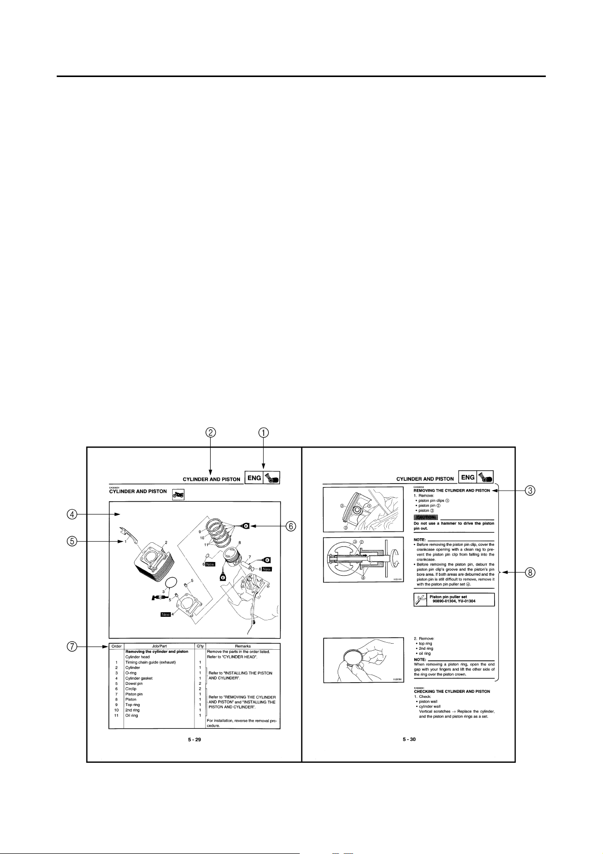
To help identify parts and clarify procedure steps, there are exploded diagrams at the start of
each removal and disassembly section.
5
Numbers are given in the order of the jobs in the exploded diagram. A circled number indicates a
disassembly step.
6
Symbols indicate parts to be lubricated or replaced.
Refer to “SYMBOLS”.
7
A job instruction chart accompanies the exploded diagram, providing the order of jobs, names of
parts, notes in jobs, etc.
8
Jobs requiring more information (such as special tools and technical data) are described sequentially.
Page 5
12
GEN
SPEC
INFO
34
CHK
CHAS
ADJ
56
ENG
78
CARB
EAS00009
SYMBOLS
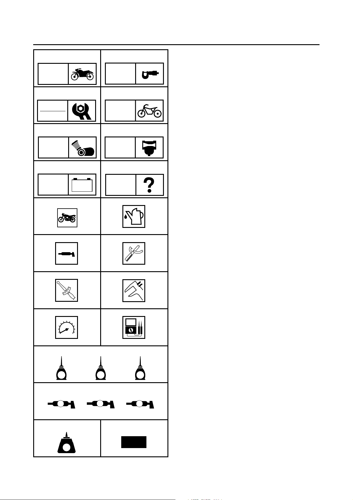
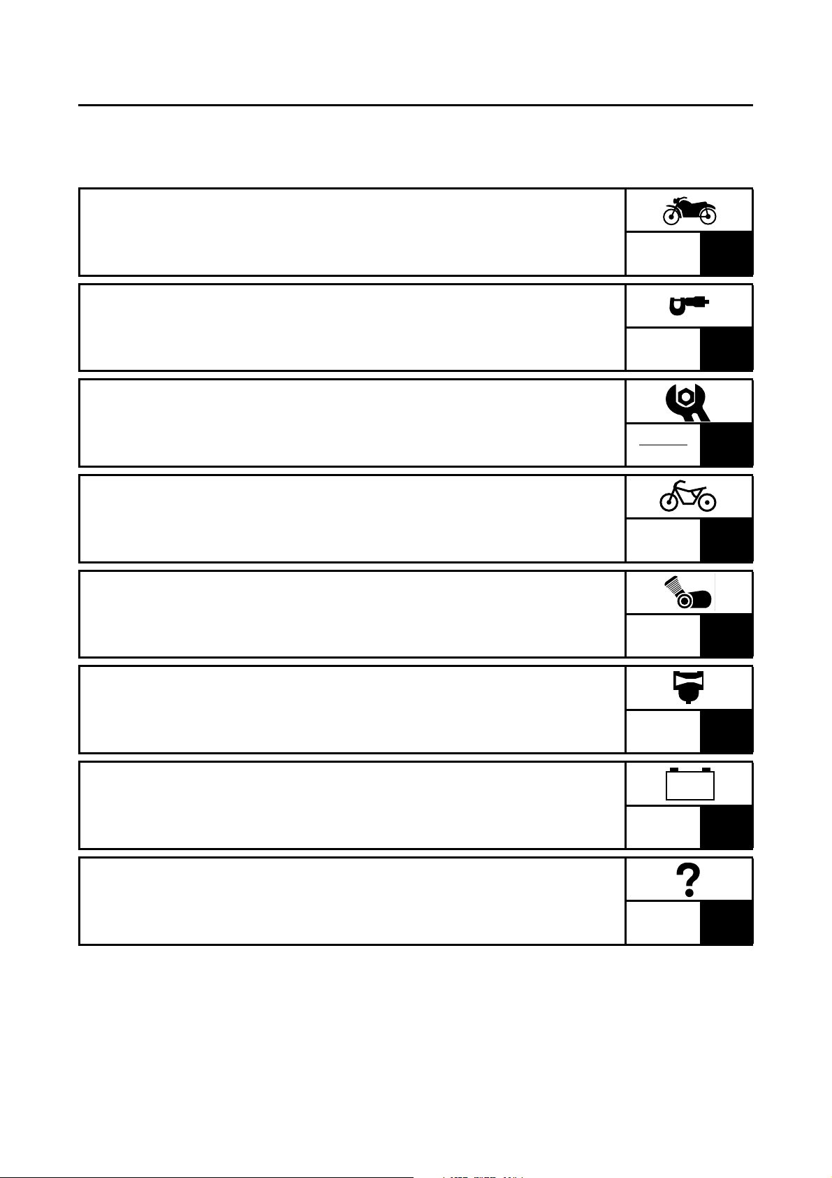
The following symbols are not relevant to
every vehicle. Symbols 1 to 8 indicate the
subject of each chapter.
General information
1
Specifications
2
Periodic checks and adjustments
3
Chassis
4
Engine
5
Carburetor
6
Electrical system
7
Troubleshooting
8
–+
TRBL
ELEC
SHTG
90
AB
CD
T
.
R
.
EF
GHI
LS
G
M
M
E
JKL
B
Symbols 9 to F indicate the following.
Serviceable with engine mounted
9
Filling fluid
0
Lubricant
A
Special tool
B
Tightening torque
C
Wear limit, clearance
D
Engine speed
E
Electrical data
F
Symbols G to L in the exploded diagrams
indicate the types of lubricants and lubrication
points.
Engine oil
G
Gear oil
H
Molybdenum-disulfide oil
I
Wheel-bearing grease
J
Lithium-soap-based grease
K
Molybdenum-disulfide grease
L
MN
LT
New
Symbols M to N in the exploded diagrams
indicate the following.
®
Apply locking agent (LOCTITE
M
Replace the part
N
)
Page 6
EAS00011
– +
TABLE OF CONTENTS
GENERAL INFORMATION
SPECIFICATIONS
PERIODIC CHECKS AND
ADJUSTMENTS
CHASSIS
ENGINE
GEN
INFO
SPEC
CHK
ADJ
CHAS
ENG
1
2
3
4
5
CARBURETOR
ELECTRICAL SYSTEM
TROUBLESHOOTING
CARB
ELEC
TRBL
SHTG
6
7
8
Page 7

CHAPTER 1
GENERAL INFORMATION
GEN
INFO
VEHICLE IDENTIFICATION
VEHICLE IDENTIFICATION NUMBER .....................................................1-1
MODEL LABEL..........................................................................................1-1
IMPORTANT INFORMATION
PREPARATION FOR REMOVAL AND DISASSEMBLY........................... 1-2
REPLACEMENT PARTS...........................................................................1-2
GASKETS, OIL SEALS AND O-RINGS .................................................... 1-2
LOCK WASHERS/PLATES AND COTTER PINS .....................................1-3
BEARINGS AND OIL SEALS ....................................................................1-3
CIRCLIPS ..................................................................................................1-3
CHECKING THE CONNECTIONS
SPECIAL TOOLS
............................................................................................1-5
............................................................................1-1
.........................................................................1-2
..................................................................1-4
Page 8
1
1
VEHICLE IDENTIFICATION
EAS00014
GENERAL INFORMATION
VEHICLE IDENTIFICATION
EAS00017
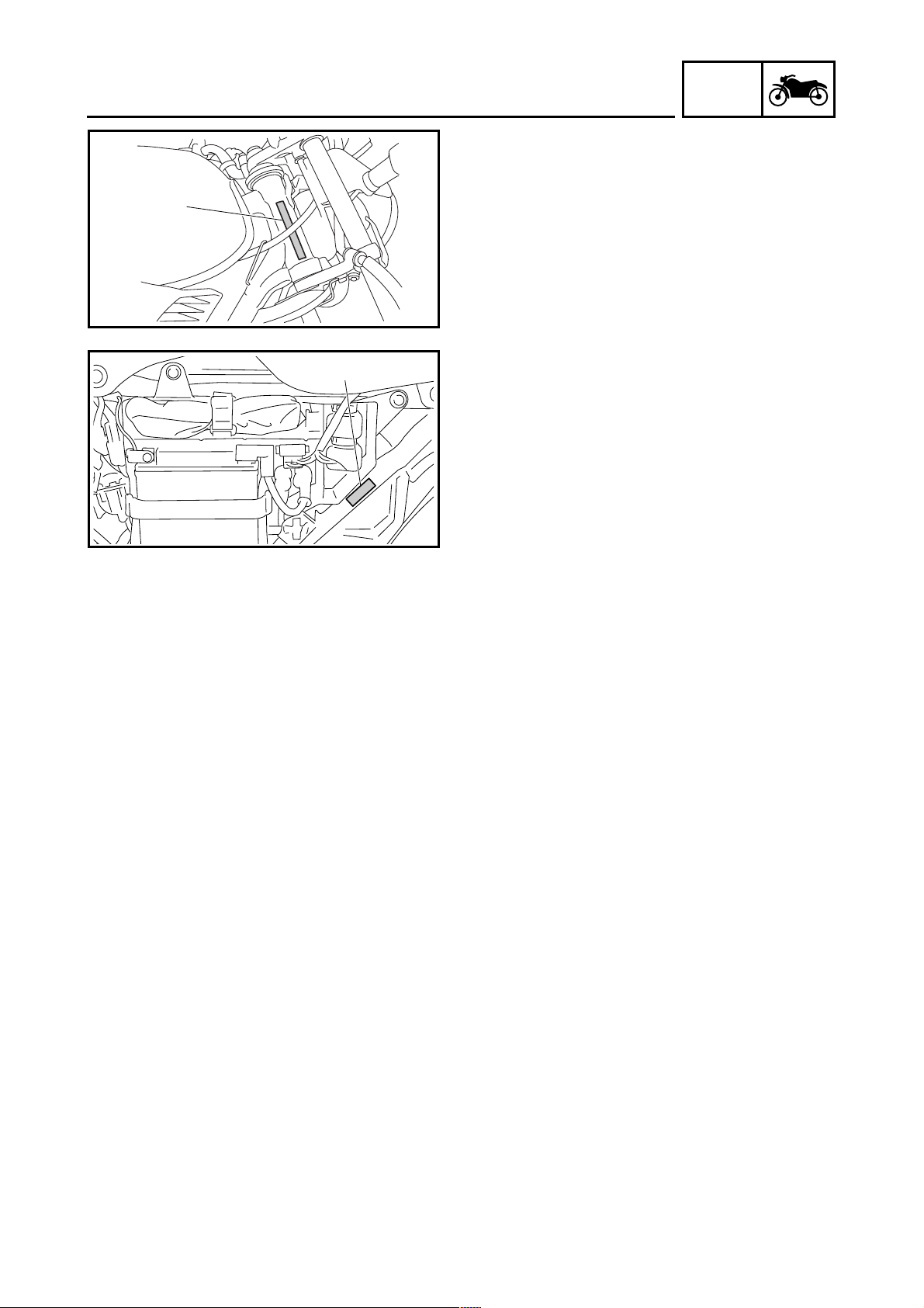
VEHICLE IDENTIFICATION NUMBER
The vehicle identification number 1 is
stamped into the right side of the steering head
pipe.
EAS00018
MODEL LABEL
The model label 1 is affixed to the frame. This
information will be needed to order spare
parts.
GEN
INFO
1 - 1
Page 9
IMPORTANT INFORMATION
EAS00020
IMPORTANT INFORMATION
PREPARATION FOR REMOVAL AND
DISASSEMBLY
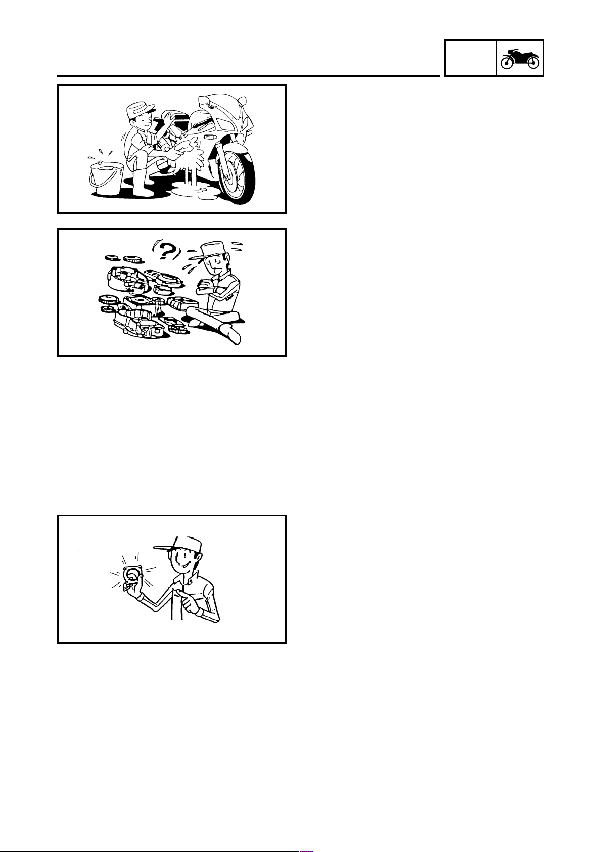
1. Before removal and disassembly, remove all
dirt, mud, dust and foreign material.
2. Use only the proper tools and cleaning
equipment.
Refer to the “SPECIAL TOOLS”.
3. When disassembling, always keep mated
parts together. This includes gears, cylinders, pistons and other parts that have been
“mated” through normal wear. Mated parts
must always be reused or replaced as an
assembly.
4. During disassembly, clean all of the parts
and place them in trays in the order of disassembly. This will speed up assembly and
allow for the correct installation of all parts.
5. Keep all parts away from any source of fire.
GEN
INFO
EAS00021
REPLACEMENT PARTS
Use only genuine Yamaha parts for all
replacements. Use oil and grease recommended by Yamaha for all lubrication jobs.
Other brands may be similar in function and
appearance, but inferior in quality.
EAS00022
GASKETS, OIL SEALS AND O-RINGS
1. When overhauling the engine, replace all
gaskets, seals and O-rings. All gasket surfaces, oil seal lips and O-rings must be
cleaned.
2. During reassembly, properly oil all mating
parts and bearings and lubricate the oil seal
lips with grease.
1 - 2
Page 10
IMPORTANT INFORMATION
EAS00023
LOCK WASHERS/PLATES AND COTTER
PINS
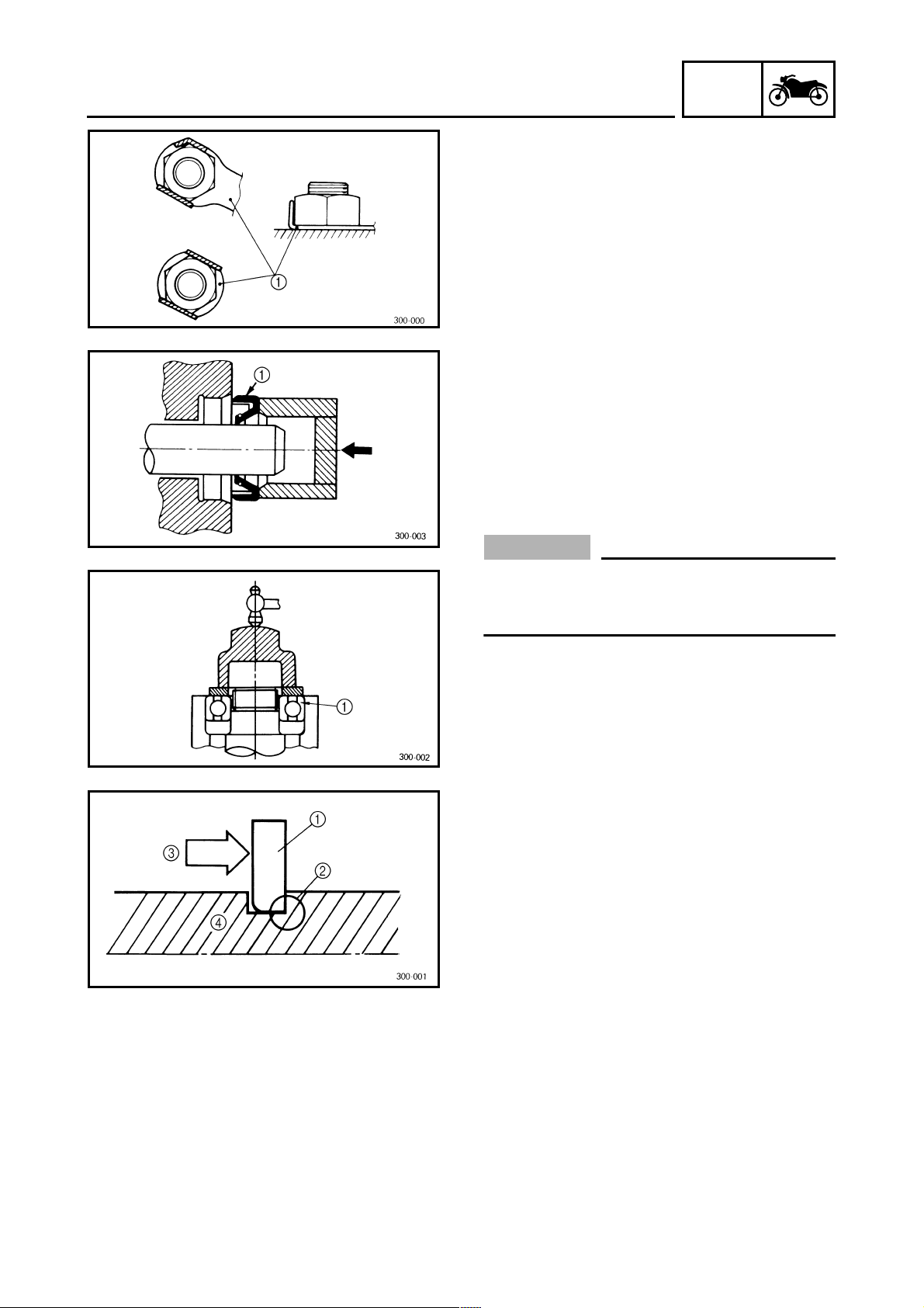
After removal, replace all lock washers/plates
1
and cotter pins. After the bolt or nut has
been tightened to specification, bend the lock
tabs along a flat of the bolt or nut.
EAS00024
BEARINGS AND OIL SEALS
Install bearings and oil seals so that the manufacturer’s marks or numbers are visible. When
installing oil seals, lubricate the oil seal lips
with a light coat of lithium-soap-based grease.
Oil bearings liberally when installing, if appropriate.
Oil seal
1
GEN
INFO
CAUTION:
_
Do not spin the bearing with compressed
air because this will damage the bearing
surfaces.
Bearing
1
EAS00025
CIRCLIPS
Before reassembly, check all circlips carefully
and replace damaged or distorted circlips.
Always replace piston pin clips after one use.
When installing a circlip 1, make sure the
sharp-edged corner 2 is positioned opposite
the thrust 3 that the circlip receives.
Shaft
4
1 - 3
Page 11
CHECKING THE CONNECTIONS
EAS00026
CHECKING THE CONNECTIONS
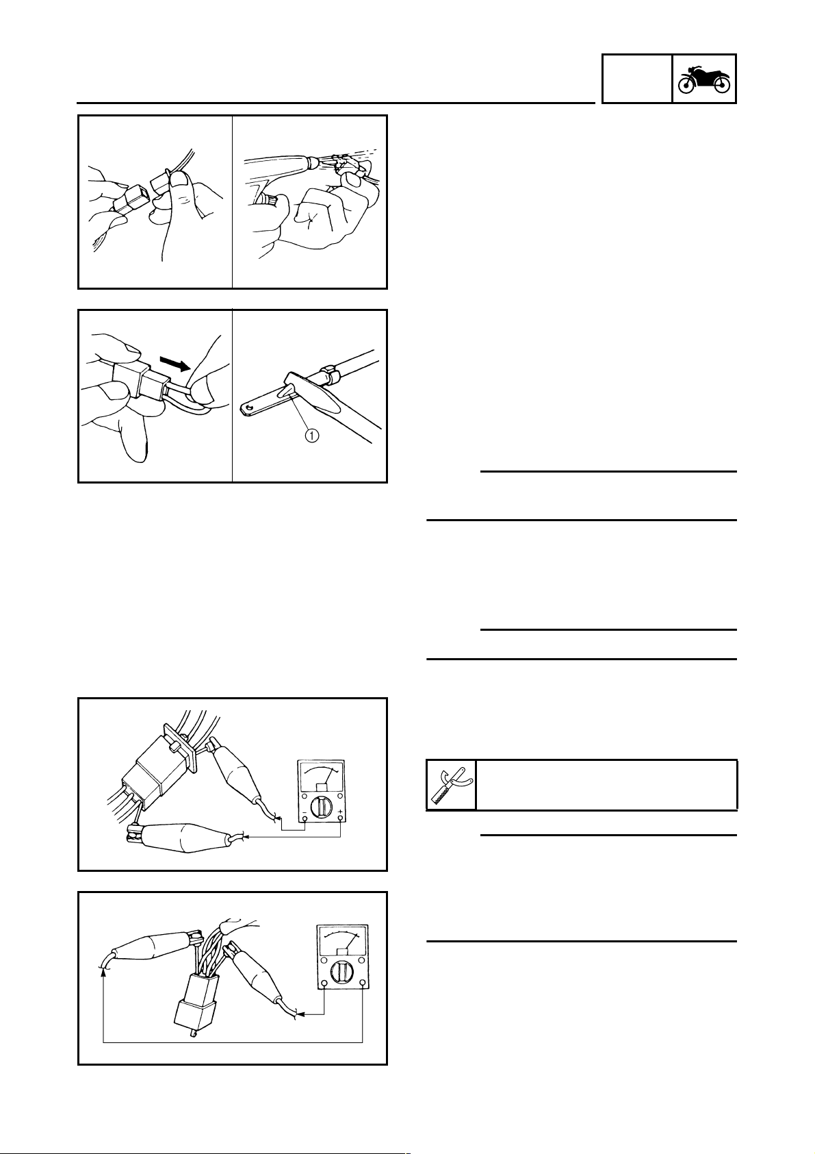
Check the leads, couplers, and connectors for
stains, rust, moisture, etc.
1. Disconnect:
• lead
• coupler
• connector
2. Check:
• lead
• coupler
• connector
Moisture → Dry with an air blower.
Rust/stains → Connect and disconnect several times.
3. Check:
• all connections
Loose connection → Connect properly.
NOTE:
_
If the pin 1 on the terminal is flattened, bend it
up.
GEN
INFO
4. Connect:
• lead
• coupler
• connector
NOTE:
_
Make sure all connections are tight.
5. Check:
• continuity
(with the pocket tester)
Pocket tester
90890-03112, YU-03112-C
NOTE:
_
• If there is no continuity, clean the terminals.
• When checking the wire harness, perform
steps (1) to (3).
• As a quick remedy, use a contact revitalizer
available at most part stores.
1 - 4
Page 12
GEN
SPECIAL TOOLS
EAS00027
SPECIAL TOOLS
The following special tools are necessary for complete and accurate tune-up and assembly. Use
only the appropriate special tools as this will help prevent damage caused by the use of inappropriate tools or improvised techniques. Special tools, part numbers or both may differ depending on the
country.
When placing an order, refer to the list provided below to avoid any mistakes.
NOTE:
• For U.S.A. and Canada, use part number starting with “YM-”, “YU-”, or “ACC-”.
• For others, use part number starting with “90890-”.
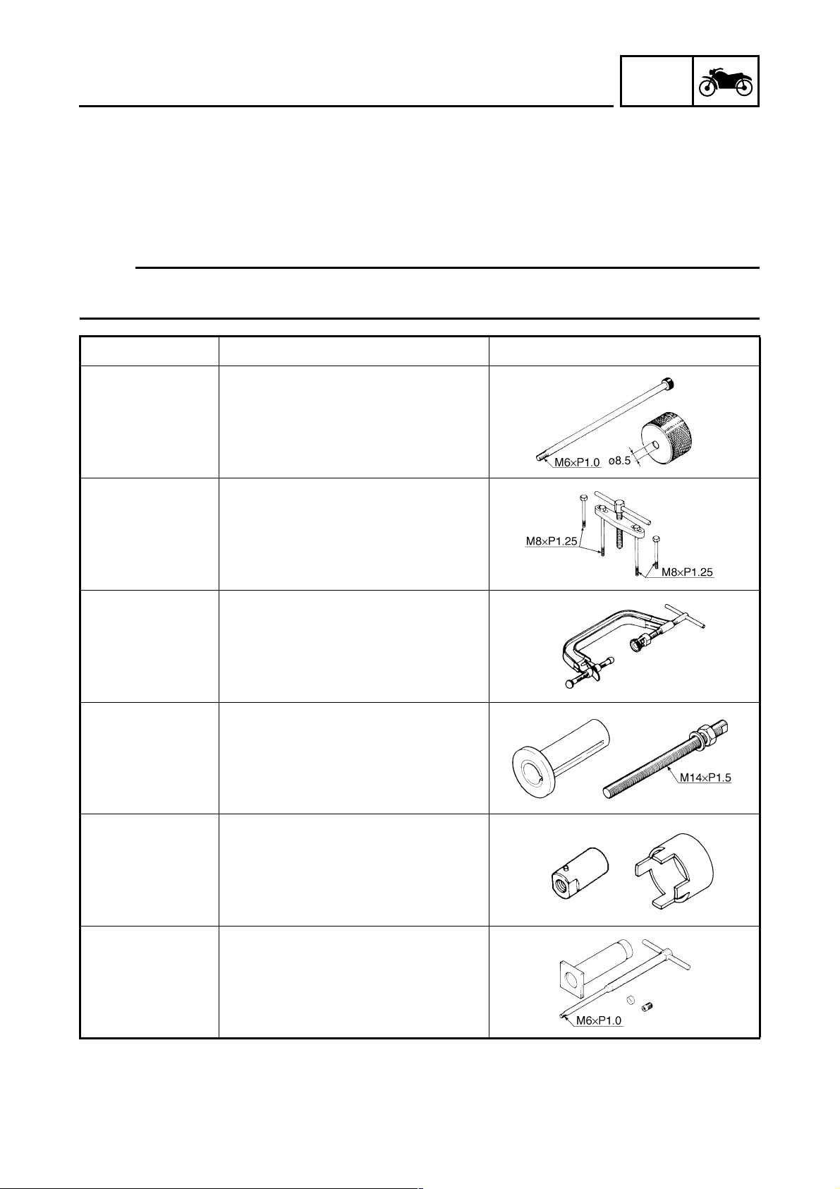
Tool No. Tool name/Function Illustration
INFO
Slide hammer bolt
90890-01083
YU-01083-1
Weight
90890-01084
YU-01083-3
90890-01135
YU-01135-B
90890-04019
YM-04019
Pot
90890-01274
YU-90058
YU-90059
Bolt
90890-01275
YU-90060
Slide hammer bolt
Weight
These tools are used to remove or install
the rocker arm shafts.
Crankcase separating tool
This tool is used to remove the crankshaft.
Valve spring compressor
This tool is used to remove or install the
valve assemblies.
Crankshaft installer pot
Crankshaft installer bolt
These tools are used to install the crankshaft.
Adapter
90890-01278
YU-90063
Spacer
90890-04081
YM-91044
90890-01304
YU-01304
Adapter (M12)
Spacer (crankshaft installer)
These tools are used to install the crankshaft.
Piston pin puller set
This tool is used to remove the piston pin.
1 - 5
Page 13
GEN
SPECIAL TOOLS
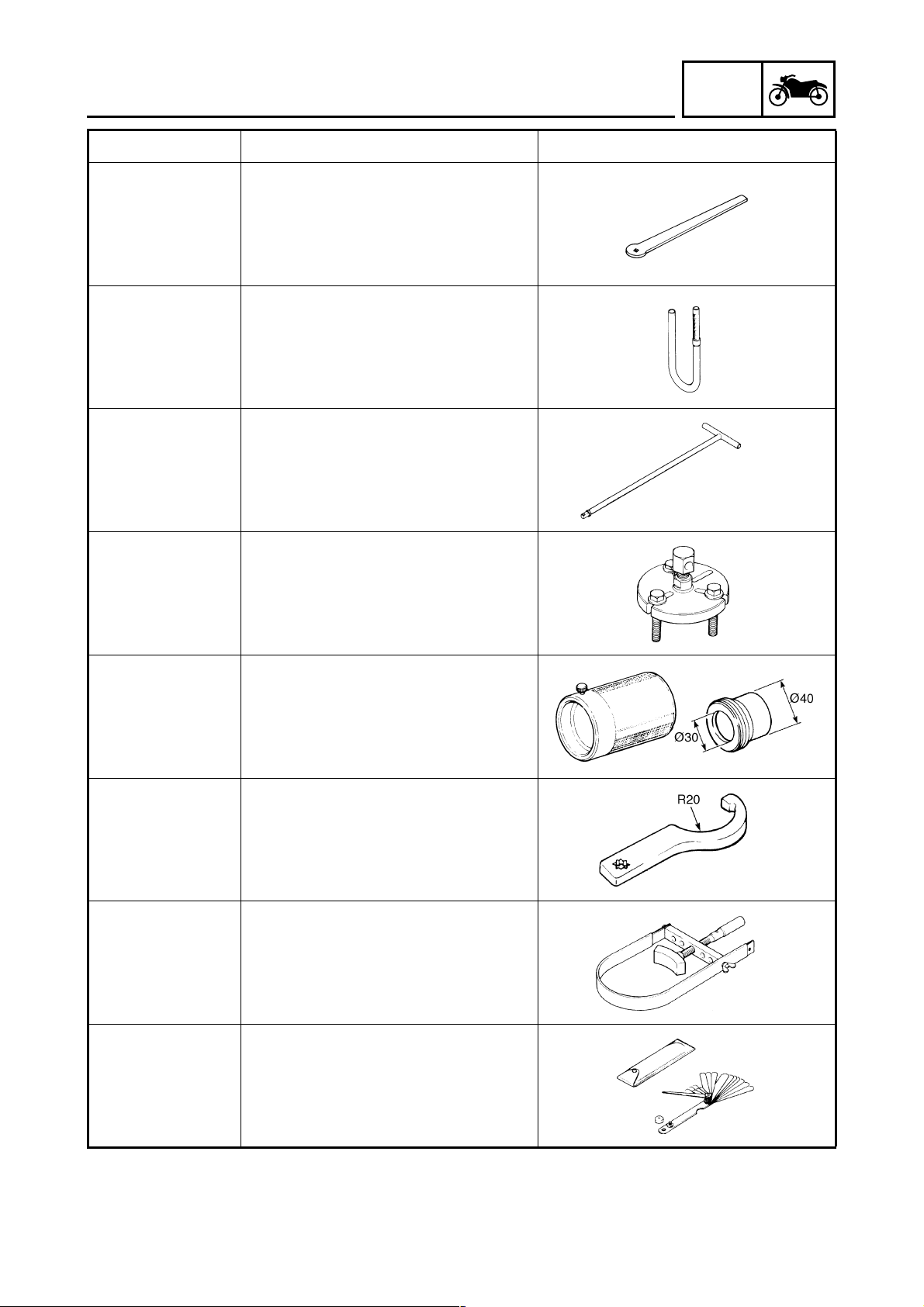
Tool No. Tool name/Function Illustration
Tappet adjusting tool
90890-01311
YM-08035-A
This tool is used to adjust the valve clearance.
Fuel level gauge
90890-01312
YM-01312-A
This gauge is used to measure the fuel
level in the float chamber.
T-handle
90890-01326
YM-01326
This tool is used to hold the 14 mm hexagon nut/socket wrench when removing or
installing the damper rod.
INFO
90890-01362
YU-33270-B
Weight
90890-01367
YM-A9409-7
YM-A5142-4
Attachment
90890-01400
90890-01403
YU-33975
90890-01701
YS-01880-A
Flywheel puller
This tool is used to remove the generator
rotor.
Fork seal driver weight
Fork seal driver attachment (ø30)
These tools are used to install the oil
seal, dust seal, and the outer tube bushing of the front fork legs.
Steering nut wrench
This tool is used to loosen or tighten the
steering ring nuts.
Sheave holder
This tool is used to hold the A.C. magneto
rotor when loosening or tightening the
A.C. magneto rotor nut.
90890-03079
YM-34483
Thickness gauge
This tool is used to measure the valve
clearance.
1 - 6
Page 14
GEN
SPECIAL TOOLS
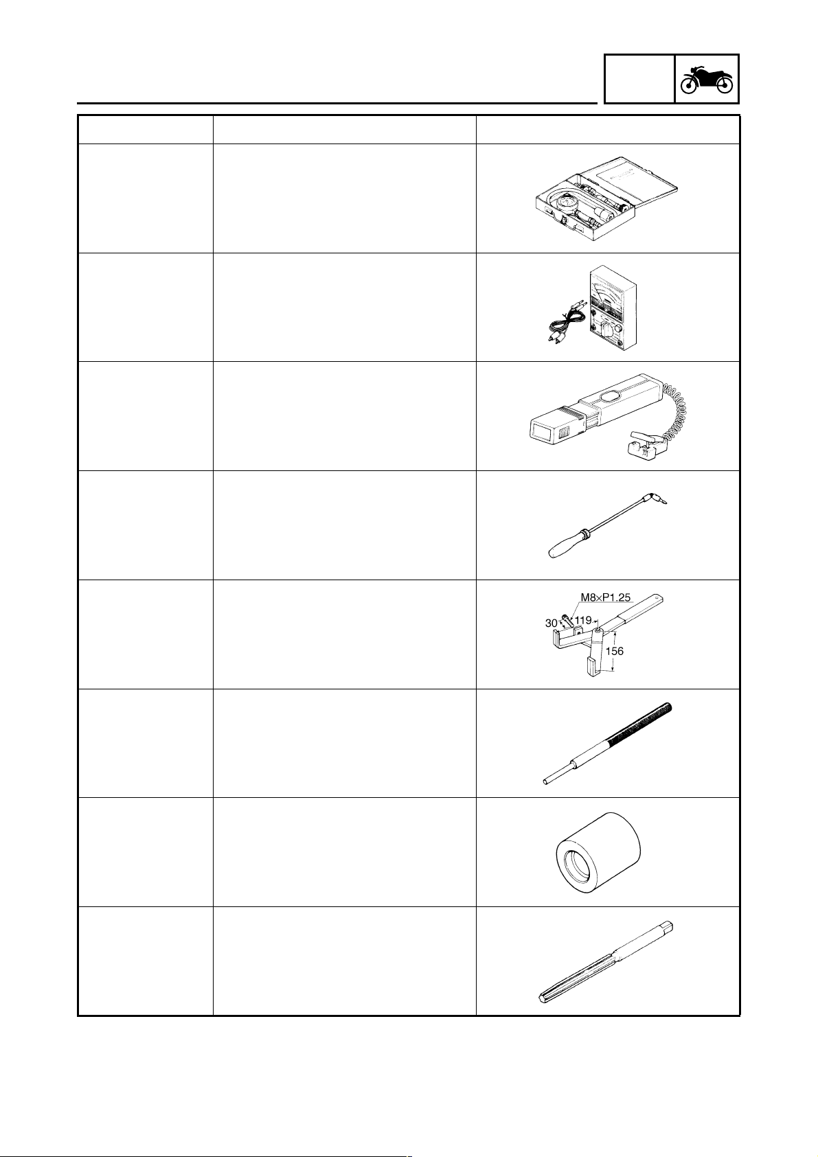
Tool No. Tool name/Function Illustration
Compression gauge
90890-03081
YU-33223
These tools are used to measure the
engine compression.
Pocket tester
90890-03112
YU-03112-C
This tool is used to check the electrical
system.
Timing light
90890-03141
YU-03141
This tool is used to check the ignition timing.
INFO
90890-03158
90890-04086
YM-91042
90890-04097
YM-04097
90890-04098
YM-04098
Carburetor angle driver
This tool is used to turn the air screw
when adjusting the engine idling speed.
Universal clutch holder
This tool is needed to hold the clutch
boss when removing or installing the
boss nut.
Valve guide remover (ø5)
This tool is needed to remove and install
the valve guides.
Valve guide installer (ø5)
This tool is needed to install the valve
guides.
90890-04099
YM-04099
Valve guide reamer (ø5)
This tool is needed to rebore the new
valve guides.
1 - 7
Page 15
GEN
SPECIAL TOOLS
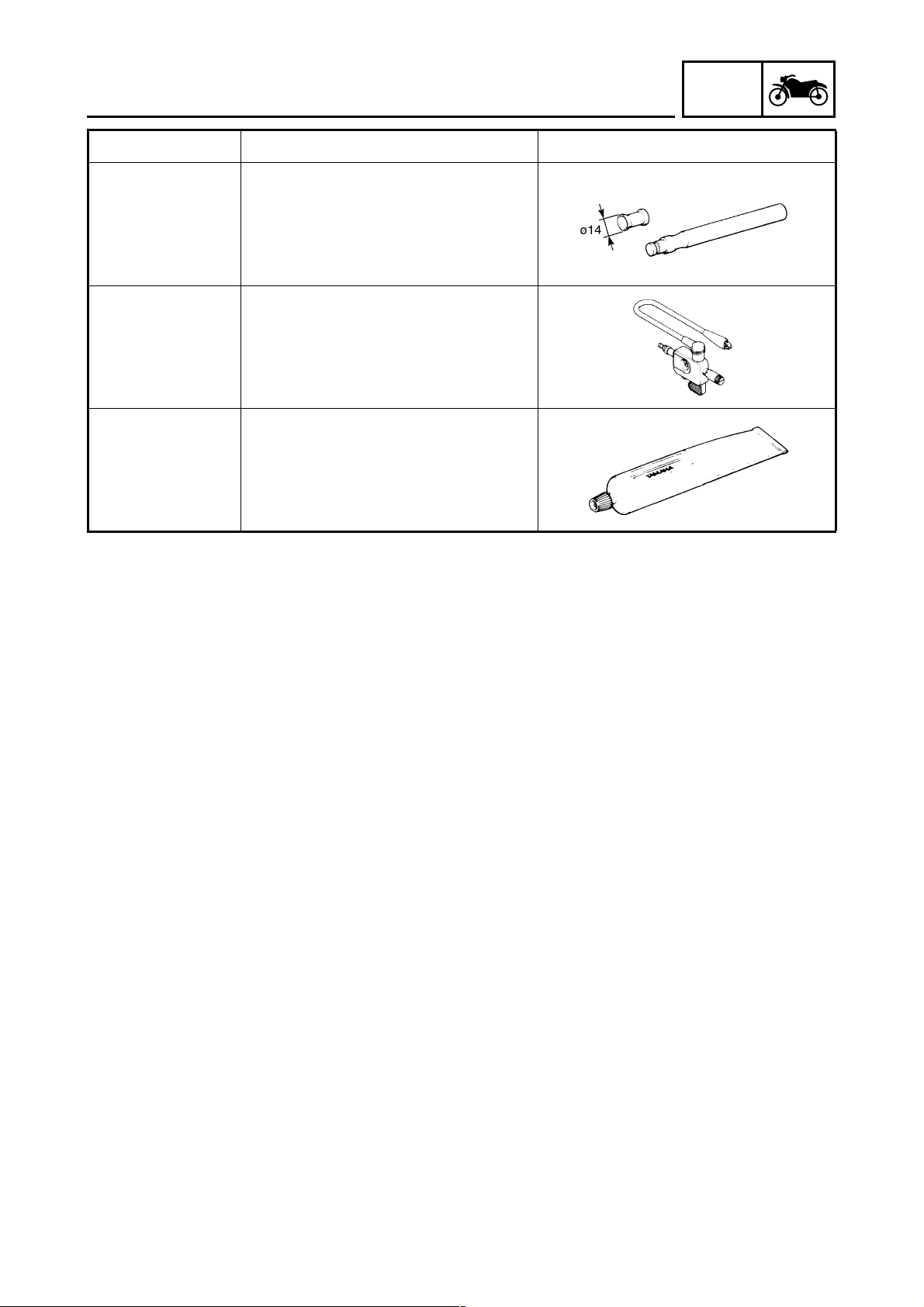
Tool No. Tool name/Function Illustration
Valve lapper
90890-04101
This tool is used for lapping the valves.
Ignition checker
90890-06754
YM-34487
This tool is used to check the ignition system components.
Yamaha bond No. 1215
90890-85505
This bond is used to seal two mating surfaces (e.g., crankcase mating surfaces).
INFO
1 - 8
Page 16

CHAPTER 2
SPECIFICATIONS
SPEC
GENERAL SPECIFICATIONS
ENGINE SPECIFICATIONS
CHASSIS SPECIFICATIONS
ELECTRICAL SPECIFICATIONS
CONVERSION TABLE
GENERAL TIGHTENING TORQUE SPECIFICATIONS
TIGHTENING TORQUES
ENGINE TIGHTENING TORQUES.........................................................2-17
CHASSIS TIGHTENING TORQUES.......................................................2-19
LUBRICATION POINTS AND LUBRICANT TYPES
ENGINE...................................................................................................2-21
CHASSIS.................................................................................................2-22
..................................................................................2-16
........................................................................2-1
............................................................................2-2
........................................................................2-10
.................................................................2-14
...............................2-16
..............................................................................2-17
....................................2-21
LUBRICATION DIAGRAMS
CABLE ROUTING
.........................................................................................2-25
..........................................................................2-23
Page 17
GENERAL SPECIFICATIONS
SPECIFICATIONS
GENERAL SPECIFICATIONS
Model YBR125
SPEC
Model code
Dimensions
Overall length 1,980 mm (78.0 in)
Overall width 745 mm (29.3 in)
Overall height 1,080 mm (42.5 in)
Seat height 780 mm (30.7 in)
Wheelbase 1,290 mm (50.8 in)
Minimum ground clearance 175 mm (6.89 in)
Minimum turning radius 1,750 mm (68.9 in)
Weight
Wet (with oil and full fuel tank) 120.0 kg (265 lb)
Maximum load (total of cargo, rider, passen-
ger, and accessories)
3D91
200.0 kg (441 lb)
2 - 1
Page 18
ENGINE SPECIFICATIONS
SPEC
ENGINE SPECIFICATIONS
Item Standard Limit
Engine
Engine type Air-cooled 4-stroke, SOHC ----
3
Displacement 123.7 cm
Cylinder arrangement Forward-inclined single cylinder ---Bore × stroke 54.0 × 54.0 mm (2.13 × 2.13 in) ---Compression ratio 10.0 : 1 ---Standard compression pressure
(at sea level)
Starting system Electric starter and kickstarter ----
Fuel
Recommended fuel Regular unleaded gasoline only ---Fuel tank capacity 12.0 L (2.64 Imp gal, 3.17 US gal) ---Fuel reserve amount 3.0 L (0.66 Imp gal, 0.79 US gal) ----
Engine oil
Type SAE10W30, SAE10W40, SAE15W40,
Recommended engine oil grade API service SE, SF, SG type or higher ---Lubrication system Wet sump ---Engine oil quantity
Total amount 1.20 L (1.06 Imp qt, 1.27 US qt) ---Periodic oil change 1.00 L (0.88 Imp qt, 1.06 US qt) ----
Oil filter type Wire mesh ----
Oil pump
Oil pump type Trochoid ---Inner-rotor-to-outer-rotor-tip-clearance
Outer-rotor-to-oil-pump-housing
clearance
Oil pump-housing-to-inner-rotor-and-
outer-rotor clearance
Spark plug
Model/manufacturer CR6HSA/NGK ---Spark plug gap 0.6 ~ 0.7 mm (0.024 ~ 0.028 in) ----
Cylinder head
Volume 15.20 ~ 15.60 cm
Maximum warpage ---- 0.05 mm
1,200 kPa (12.0 kgf/cm
SAE20W40 or SAE20W50
0.07 mm (0.0028 in) 0.15 mm
0.13 ~ 0.19 mm (0.0051 ~ 0.0075 in) 0.26 mm
0.06 ~ 0.10 mm (0.0024 ~ 0.0039 in) 0.17 mm
(7.55 cu.in) ----
2
, 170.7 psi) ----
(0.0059 in)
(0.010 in)
(0.0067 in)
3
(0.93 ~ 0.95 cu.in) ----
(0.0020 in)
----
2 - 2
Page 19

ENGINE SPECIFICATIONS
Item Standard Limit
Camshaft
Drive system Chain drive (left) ---Intake camshaft lobe dimensions
A
B
Measurement A 25.881 ~ 25.981 mm (1.0189 ~ 1.0229 in) 25.851 mm
Measurement B 21.194 ~ 21.294 mm (0.8344 ~ 0.8383 in) 21.164 mm
Exhaust camshaft lobe dimensions
SPEC
(1.0178 in)
(0.8332 in)
A
B
Measurement A 25.841 ~ 25.941 mm (1.0174 ~ 1.0213 in) 25.811 mm
(1.0162 in)
Measurement B 20.997 ~ 21.097 mm (0.8267 ~ 0.8306 in) 20.967 mm
(0.8255 in)
Maximum camshaft runout ---- 0.03 mm
(0.0012 in)
Timing chain
Model/number of links 92RH2005-90M/90 ---Tensioning system Automatic ----
Rocker arm/rocker arm shaft
Rocker arm inside diameter 10.000 ~ 10.015 mm (0.3937 ~ 0.3943 in) 10.030 mm
(0.3949 in)
Rocker arm shaft outside diameter 9.981 ~ 9.991 mm (0.3930 ~ 0.3933 in) 9.950 mm
(0.3917 in)
Rocker-arm-to-rocker-arm-shaft
clearance
0.009 ~ 0.034 mm (0.0003 ~ 0.0013 in) 0.080 mm
(0.003 in)
2 - 3
Page 20
ENGINE SPECIFICATIONS
Item Standard Limit
Valves, valve seats, valve guides
Valve clearance (cold)
Intake 0.08 ~ 0.12 mm (0.0031 ~ 0.0047 in) ---Exhaust 0.10 ~ 0.14 mm (0.0039 ~ 0.0055 in) ----
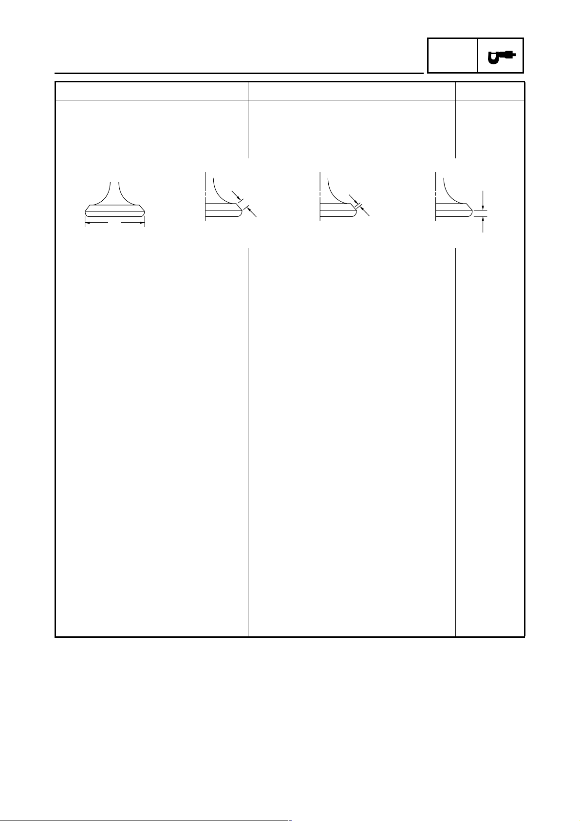
Valve dimensions
SPEC
B
A
Head Diameter Face Width Seat Width Margin Thickness
Valve head diameter A
Intake 25.90 ~ 26.10 mm (1.0197 ~ 1.0276 in) ---Exhaust 21.90 ~ 22.10 mm (0.8622 ~ 0.8701 in) ----
Valve face width B
Intake 1.100 ~ 3.000 mm (0.0433 ~ 0.1181 in) ---Exhaust 1.700 ~ 2.800 mm (0.0669 ~ 0.1102 in) ----
Valve seat width C
Intake 0.90 ~ 1.10 mm (0.0354 ~ 0.0433 in) ---Exhaust 0.90 ~ 1.10 mm (0.0354 ~ 0.0433 in) ----
Valve margin thickness D
Intake 0.40 ~ 0.80 mm (0.0157 ~ 0.0315 in) ---Exhaust 0.80 ~ 1.20 mm (0.0315 ~ 0.0472 in) ----
Valve stem diameter
Intake 4.975 ~ 4.990 mm (0.1959 ~ 0.1965 in) 4.945 mm
Exhaust 4.960 ~ 4.975 mm (0.1953 ~ 0.1959 in) 4.930 mm
Valve guide inside diameter
Intake 5.000 ~ 5.012 mm (0.1969 ~ 0.1973 in) 5.050 mm
Exhaust 5.000 ~ 5.012 mm (0.1969 ~ 0.1973 in) 5.050 mm
Valve-stem-to-valve-guide clearance
Intake 0.010 ~ 0.037 mm (0.0004 ~ 0.0015 in) 0.080 mm
Exhaust 0.025 ~ 0.052 mm (0.0010 ~ 0.0020 in) 0.100 mm
C
(0.1945 in)
(0.1941 in)
(0.1988 in)
(0.1988 in)
(0.0032 in)
(0.0039 in)
D
2 - 4
Page 21
ENGINE SPECIFICATIONS
Item Standard Limit
Valve stem runout ---- 0.010 mm
Valve seat width (cylinder head side)
Intake 0.90 ~ 1.10 mm (0.0354 ~ 0.0433 in) 1.6 mm
Exhaust 0.90 ~ 1.10 mm (0.0354 ~ 0.0433 in) 1.6 mm
Valve springs
Free length
Intake 47.06 mm (1.85 in) 44.71 mm
Exhaust 47.06 mm (1.85 in) 44.71 mm
Installed length (valve closed)
Intake 25.6 mm (1.01 in) ---Exhaust 25.6 mm (1.01 in) ----
Spring rate
Intake (K1) 8.01 N/mm (0.82 kg/mm, 45.74 ft · lb) ---Exhaust (K1) 8.01 N/mm (0.82 kg/mm, 45.74 ft · lb) ---Intake (K2) 9.33 N/mm (0.95 kg/mm, 53.27 ft · lb) ---Exhaust (K2) 9.33 N/mm (0.95 kg/mm, 53.27 ft · lb) ----
Compressed spring force (installed)
Intake 160.0 ~ 184.0 N
(16.32 ~ 18.76 kg, 35.97 ~ 41.36 lb)
Exhaust 160.0 ~ 184.0 N
(16.32 ~ 18.76 kg, 35.97 ~ 41.36 lb)
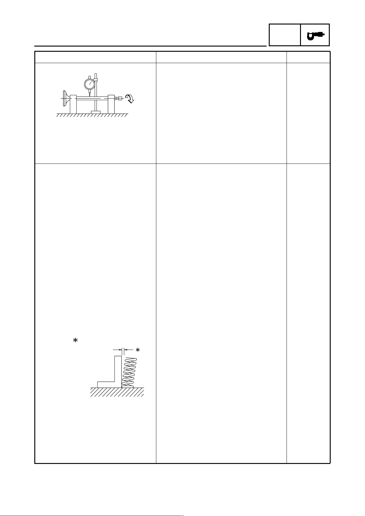
Spring tilt
SPEC
(0.0004 in)
(0.06 in)
(0.06 in)
(1.76 in)
(1.76 in)
----
----
Intake ---- 2.5°/2.1 mm
(2.5°/0.08 in)
Exhaust ---- 2.5°/2.1 mm
(2.5°/0.08 in)
Winding direction (top view)
Intake Clockwise ---Exhaust Clockwise ----
2 - 5
Page 22
ENGINE SPECIFICATIONS
Item Standard Limit
Cylinder
Bore 54.024 ~ 54.056 mm (2.1269 ~ 2.1282 in) 54.156 mm
Measuring point 40 mm (1.57 in) ----
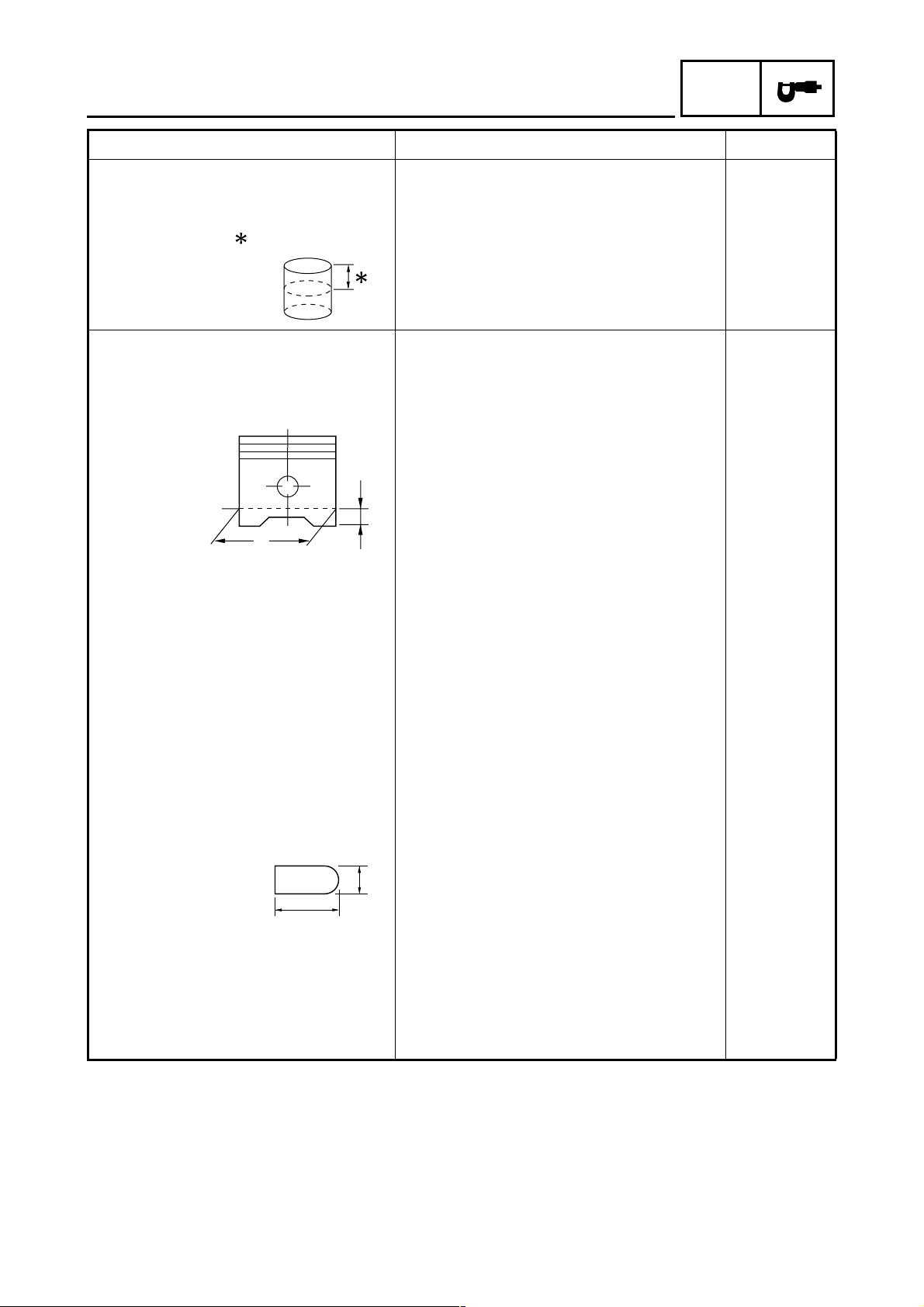
Piston
Piston-to-cylinder clearance 0.019 ~ 0.035 mm (0.0007 ~ 0.0014 in) 0.15 mm
Diameter D 53.997 ~ 54.029 mm (2.1259 ~ 2.1271 in) ----
H
D
SPEC
(2.1321 in)
(0.0059 in)
Height H 4.8 mm (0.19 in) ---Piston pin bore (in the piston)
Diameter 15.002 ~ 15.013 mm (0.5906 ~ 0.5911 in) 15.043 mm
(0.5922 in)
Offset 0.50 mm (0.0197 in) ---Offset direction Intake side ----
Piston pin
Outside diameter 14.991 ~ 15.000 mm (0.5902 ~ 0.5906 in) 14.971 mm
(0.5894 in)
Piston-pin-to-piston-pin-bore clearance
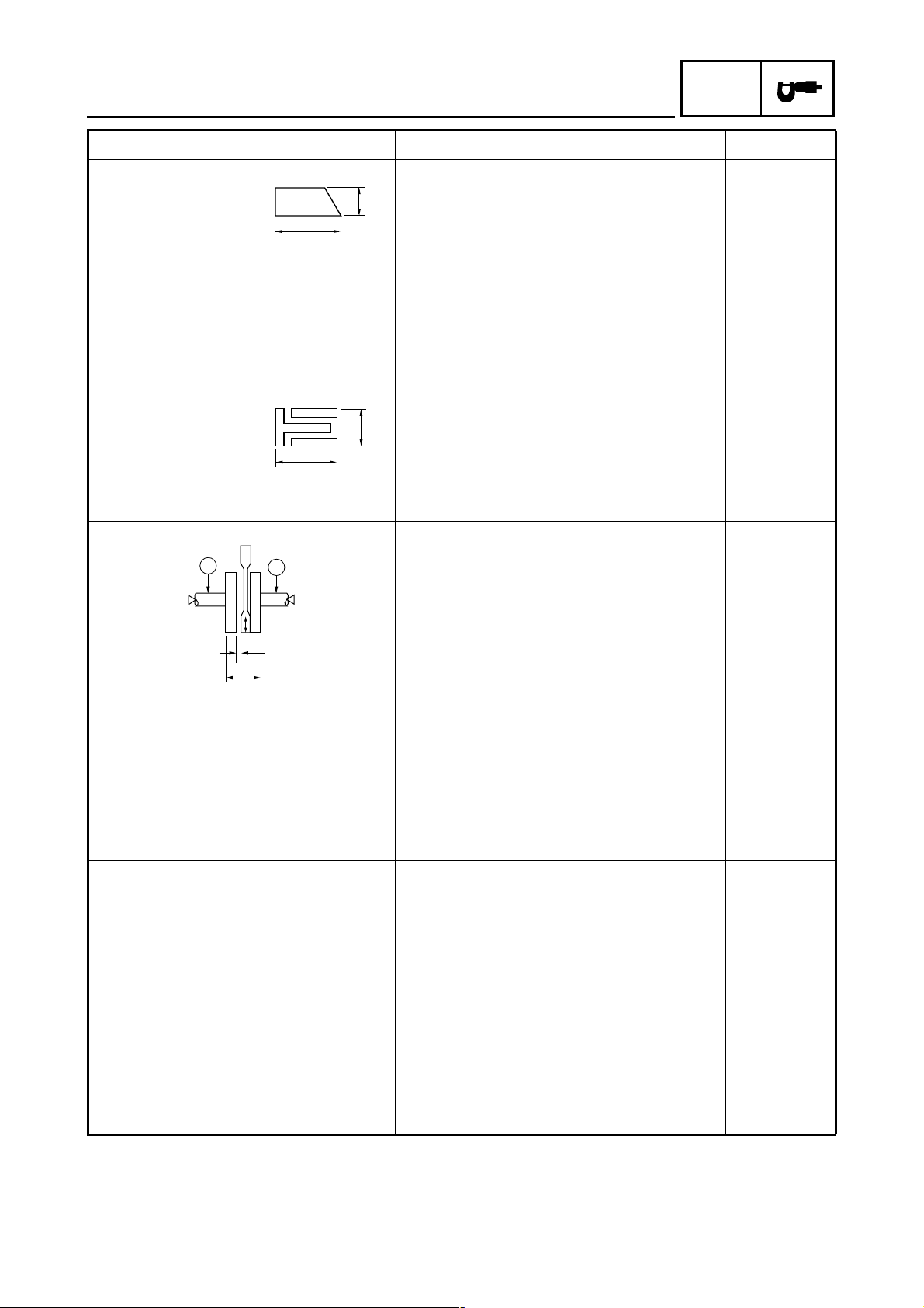
Piston rings
Top ring
T
Ring type Barrel ---Dimensions (B × T) 1.00 × 2.10 mm (0.039 × 0.082 in) ---End gap (installed) 0.15 ~ 0.30 mm (0.006 ~ 0.012 in) 0.55 mm
Ring side clearance 0.035 ~ 0.070 mm (0.0014 ~ 0.0028 in) 0.120 mm
0.002 ~ 0.022 mm (0.0001 ~ 0.0009 in) 0.072 mm
(0.0028 in)
B
(0.022 in)
(0.0047 in)
2 - 6
Page 23
ENGINE SPECIFICATIONS
Item Standard Limit
2nd ring
B
T
Ring type Taper ---Dimensions (B × T) 1.00 × 2.10 mm (0.039 × 0.082 in) ---End gap (installed) 0.30 ~ 0.45 mm (0.012 ~ 0.018 in) 0.80 mm
Ring side clearance 0.020 ~ 0.060 mm (0.0008 ~ 0.0024 in) 0.120 mm
Oil ring
B
T
Dimensions (B × T) 2.00 × 2.25 mm (0.079 × 0.089 in) ---End gap (installed) 0.20 ~ 0.70 mm (0.008 ~ 0.028 in) ----
Crankshaft
SPEC
(0.031 in)
(0.0047 in)
C
Width A 46.95 ~ 47.00 mm (1.848 ~ 1.850 in) ---Maximum runout C ---- 0.030 mm
Big end side clearance D 0.150 ~ 0.450 mm (0.0059 ~ 0.0177 in) ---Big end radial clearance E 0.010 ~ 0.021 mm (0.0004 ~ 0.0008 in) ----
Balancer
Balancer drive method Gear ----
Clutch
Clutch type Wet, multiple-disc ---Clutch release method Inner push, cam push ---Clutch cable free play
(at the pivot bolt of the clutch lever)
Friction plate thickness 3.00 mm (0.118 in) 2.80 mm
Plate quantity 4 pcs ---Clutch plate thickness 1.60 mm (0.06 in) ---Plate quantity 3 pcs ---Maximum warpage ---- 0.20 mm
C
E
D
A
(0.0012 in)
10 ~ 15 mm (0.39 ~ 0.59 in) ----
(0.110 in)
(0.0079 in)
2 - 7
Page 24
ENGINE SPECIFICATIONS
Item Standard Limit
Clutch spring
Free length 29.30 mm (1.15 in) 27.84 mm
Spring quantity 4 pcs ----
Long clutch push rod bending ---- 0.500 mm
Transmission
Transmission type Constant mesh 5-speed ---Primary reduction system Helical gear ---Primary reduction ratio 68/20 (3.400) ---Secondary reduction system Chain drive ---Secondary reduction ratio 45/14 (3.214) ---Operation Left foot operation ---Gear ratio
1st 37/14 (2.643) ---2nd 32/18 (1.778) ---3rd 25/19 (1.316) ---4th 23/22 (1.045) ---5th 21/24 (0.875)
Main axle runout limit ---- 0.03 mm
Drive axle runout limit ---- 0.03 mm
Shifting mechanism
Shift mechanism type Shift drum and guide bar ---Shift fork thickness 4.76 ~ 4.89 mm (0.1874 ~ 0.1925 in) ----
Kickstarter
Kickstarter type Kick and mesh ---Kickstarter pinion gear clip friction
force
Air filter
Air filter element Dry element ----
8 ~ 12 N
(0.82 ~ 1.22 kgf, 1.80 ~ 2.70 lb)
SPEC
(1.10 in)
(0.0197 in)
(0.0012 in)
(0.0012 in)
----
2 - 8
Page 25

ENGINE SPECIFICATIONS
Item Standard Limit
Carburetor
Type/quantity VM22SH/1 ---Manufacturer MIKUNI ---ID mark 3D91 00 ---Main jet #97.5 ---Main air jet ø0.9 ----
Jet needle 5EJ7-2 ---Needle jet N-7M ---Pilot air jet 1 #60
Pilot air jet 2 ø1.3
Pilot outlet ø1.0 ----
Pilot jet #15 ---Pilot screw turns out 1-1/2 ---Valve seat size ø1.8 ----
Starter jet 1 #25 ---Starter jet 2 ø0.5
Throttle cable free play
(at the flange of the throttle grip)
Fuel level
(below the float chamber mating surface)
Idling condition
Engine idling speed
Air induction system ON 1,400 ~ 1,500 r/min ----
Air induction system OFF 1,350 ~ 1,450 r/min ---CO% (air induction system OFF) 3.0 ~ 4.0% ---Intake vacuum 26.8 ~ 32.2 kPa
Oil temperature 75 ~ 85 °C (167 ~ 185 °F) ----
3 ~ 7 mm (0.12 ~ 0.28 in) ----
6.0 ~ 7.0 mm (0.24 ~ 0.28 in) ----
(201.5 ~ 242.1 mmHg, 7.93 ~ 9.53 inHg)
SPEC
----
2 - 9
Page 26
CHASSIS SPECIFICATIONS
SPEC
CHASSIS SPECIFICATIONS
Item Standard Limit
Frame
Frame type Diamond ---Caster angle 26.33° ----
Trail 90.0 mm (3.54 in) ----
Front wheel
Wheel type Cast wheel ---Rim
Size J18 × 1.60 ----
Material Aluminum ---Wheel travel 110.0 mm (4.33 in) ---Wheel runout
Maximum radial wheel runout ---- 1.0 mm
(0.04 in)
Maximum lateral wheel runout ---- 0.5 mm
(0.02 in)
Rear wheel
Wheel type Cast wheel ---Rim
Size J18 × 1.85 ----
Material Aluminum ---Wheel travel 105.0 mm (4.13 in) ---Wheel runout
Maximum radial wheel runout ---- 1.0 mm
(0.04 in)
Maximum lateral wheel runout ---- 0.5 mm
(0.02 in)
Front tire
Tire type With tube ---Size 2.75-18 42P ---Manufacturer/model CHENG SHIN/SAKURA S-901
PIRELLI/CITY DEMON
Tire pressure (cold tire)
0 ~ 90 kg (0 ~ 198 lb) 175 kPa (1.75 kgf/cm
90 kg ~ Maximum load
(198 lb ~ Maximum load)
Minimum tire tread depth ---- 1.6 mm
175 kPa (1.75 kgf/cm
2
, 25 psi) ----
2
, 25 psi) ----
(0.06 in)
----
----
2 - 10
Page 27
CHASSIS SPECIFICATIONS
Item Standard Limit
Rear tire
Tire type With tube ---Size 90/90-18 57P ---Manufacturer/model CHENG SHIN/SAKURA S-180
PIRELLI/CITY DEMON
Tire pressure (cold tire)
0 ~ 90 kg (0 ~ 198 lb) 200 kPa (2.00 kgf/cm
90 kg ~ Maximum load
(198 lb ~ Maximum load)
Minimum tire tread depth ---- 1.6 mm
Front brake
Brake type Single-disc brake ---Operation Right-hand operation ---Front disc brake
Diameter × thickness 245.0 × 4.0 mm (9.65 × 0.16 in) ----
Minimum thickness ---- 3.5 mm
Maximum deflection ---- 0.15 mm
Brake pad lining thickness-inner 6.0 mm (0.24 in) 0.8 mm
Brake pad lining thickness-outer 6.0 mm (0.24 in) 0.8 mm
Master cylinder inside diameter 12.70 mm (0.50 in) ---Caliper cylinder inside diameter 35.03 mm (1.3791 in) ---Recommended fluid DOT 3 or 4 ----
Rear brake
Brake type Drum brake ---Operation Right-foot operation ---Brake pedal position 13.5 mm (0.53 in) ---Brake pedal free play 20 ~ 30 mm (0.79 ~ 1.18 in) ----
Rear brake drum
Drum brake type Leading, trailing ---Drum inside diameter 130.0 mm (5.12 in) 131.0 mm
Lining thickness 4.0 mm (0.16 in) 2.0 mm
Shoe spring free length 50.5 mm (1.99 in) ----
280 kPa (2.80 kgf/cm
2
, 29 psi) ----
2
, 41 psi) ----
SPEC
----
----
(0.06 in)
(0.14 in)
(0.0059 in)
(0.03 in)
(0.03 in)
(5.16 in)
(0.08 in)
2 - 11
Page 28
CHASSIS SPECIFICATIONS
Item Standard Limit
Steering
Steering bearing type Ball and race bearing ---Lock-to-lock angle (left) 47° ----
Lock-to-lock angle (right) 47° ----
No./size of steel balls
Upper 16 pcs 0.250 in ----
Lower 16 pcs 0.250 in ----
Front suspension
Suspension type Telescopic fork ---Front fork type Coil spring/oil damper ---Front fork travel 120.0 mm (4.72 in) ---Spring
Free length 337.0 mm (13.27 in) 330.3 mm
Installed length 318.9 mm (12.56 in) ----
Spring rate (K1) 7.37 N/mm (0.75 kgf/mm, 42.08 lb/in) ----
Spring rate (K2) 10.78 N/mm (1.1 kgf/mm, 61.55 lb/in) ----
Spring stroke (K1) 0 ~ 75 mm (0 ~ 2.95 in) ----
Spring stroke (K2) 75 ~ 120 mm (2.95 ~ 4.72 in) ---Optional spring available No ---Fork oil
Recommended oil Fork oil 10W or equivalent ----
Quantity (each front fork leg) 0.154 L (0.136 Imp qt, 0.163 US qt) ----
Level (from the top of the inner
tube, with the inner tube fully com-
pressed, and without the fork
spring)
Inner tube outer diameter 30 mm (1.18 in) ----
Inner tube bend limit ---- 0.2 mm
Rear suspension
Suspension type Swingarm ---Spring/shock absorber type Coil spring/oil damper ---Rear shock absorber assembly travel 90.0 mm (3.54 in) ---Spring
Free length 226.5 mm (8.92 in) 222.0 mm
Installed length 219.5 mm (8.64 in) ----
Spring rate (K1) 13.30 N/mm (1.36 kgf/mm, 75.94 lb/in) ----
Spring rate (K2) 16.20 N/mm (1.65 kgf/mm, 92.50 lb/in) ----
Spring rate (K3) 24.30 N/mm (2.48 kgf/mm, 138.75 lb/in) ----
Spring stroke (K1) 0 ~ 7 mm (0 ~ 0.28 in) ----
Spring stroke (K2) 7 ~ 47 mm (0.28 ~ 1.85 in) ----
Spring stroke (K3) 47 ~ 90 mm (1.85 ~ 3.54 in) ---Optional spring available No ----
166 mm (6.54 in) ----
SPEC
(13.00 in)
(0.008 in)
(8.74 in)
2 - 12
Page 29
CHASSIS SPECIFICATIONS
Item Standard Limit
Swingarm
Free play limit (at the end of the swingarm)-radial
Free play limit (at the end of the swingarm)-axial
Drive chain
Type/manufacturer DID428V2/DAIDO ---Link quantity 118 ---Drive chain slack 20 ~ 30 mm (0.79 ~ 1.18 in) ---15-Link length limit ---- 191.5 mm
---- 1.0 mm
---- 1.0 mm
SPEC
(0.04 in)
(0.04 in)
(7.54 in)
2 - 13
Page 30
ELECTRICAL SPECIFICATIONS
SPEC
ELECTRICAL SPECIFICATIONS
Item Standard Limit
System voltage
Ignition system
Ignition system type DC. C.D.I. ---Ignition timing (B.T.D.C.) 7.0° at 1,400 r/min ---Advanced type Digital ----
DC.C.D.I.
Pickup coil resistance/color 248 ~ 372 Ω at 20 °C (68 °F)/white–red ----
C.D.I. unit model/manufacturer 3D9-00/SHY ----
Ignition coil
Model/manufacturer 5VL/SHY ---Minimum ignition spark gap 6.0 mm (0.24 in) ---Primary coil resistance 0.32 ~ 0.48 Ω at 20 °C (68 °F) ---Secondary coil resistance 5.68 ~ 8.52 kΩ at 20 °C (68 °F) ----
Spark plug cap
Material Resin ---Resistance 4.0 ~ 6.0 kΩ at 20 °C (68 °F) ----
Charging system
Type A.C. magneto ---Model/manufacturer 3D9/SHY ---Standard output 14 V 115 W at 5,000 r/min ---Charging coil resistance/color 0.64 ~ 0.96 Ω at 20 °C (68 °F)/white–white ----
Rectifier/regulator
Regulator type Semi conductor-short circuit ---Model/manufacturer SANXIN ---No load regulated voltage (DC) 13.7 ~ 14.7 V ---Rectifier capacity 8.0 A ---Withstand voltage 200 V ----
Battery
Model/manufacturer CB5L-B/TIANJIN TONG YEE INDUS-
Battery voltage/capacity 12 V/5.0 Ah ---Specific gravity 1.280 ----
Headlight
Bulb type Krypton bulb ----
Bulbs (voltage/wattage × quantity)
Headlight 12 V 35 W/35 W × 1 ---Auxiliary light 12 V 5 W × 1 ---Tail/brake light 12 V 5 W/21 W × 1 ---Front turn signal light 12 V 10 W × 2 ---Rear turn signal light 12 V 10 W × 2 ---Meter lighting 12 V 1.7 W × 4 ----
12 V ----
TRIAL
----
2 - 14
Page 31

ELECTRICAL SPECIFICATIONS
Item Standard Limit
Indicator lights
(voltage/wattage × quantity)
Neutral indicator light 14 V 3 W × 1 ---Turn signal indicator light 14 V 3 W × 2 ---High beam indicator light 14 V 3 W × 1 ----
Electric starting system
System type Constant mesh ----
Starter motor
Model/manufacturer 3D9/SHY ---Power output 0.4 kW ---Armature resistance 0.017 ~ 0.021 Ω ----
Brushes
Overall length 10.0 mm (0.39 in) 3.5 mm
Spring force 5.52 ~ 8.28 N
(563 ~ 844 gf, 19.87 ~ 29.80 oz)
Commutator diameter 22.0 mm (0.87 in) 21.0 mm
Mica undercut 1.5 mm (0.06 in) ----
Starter relay
Model/manufacturer SANXIN ---Amperage 150 A ---Coil resistance 3.6 ~ 4.4 Ω ----
Horn
Horn type Plane ---Model/manufacturer × quantity YF-12/NIKKO × 1 ---Maximum amperage 3.0 A ---Coil resistance 1.15 ~ 1.25 Ω ----
Performance 105 ~ 120 dB/2 m ----
Turn signal relay
Relay type Condenser ---Self-cancelling device built-in No ---Turn signal blinking frequency 75 ~ 95 cycles/min. ---Wattage 10 W × 2 + 1.7 W ----
Fuel gauge
Model/manufacturer LOCAL MADE ---Sender unit resistance- full 4 ~ 10 Ω at 20 °C (68 °F) ---Sender unit resistance- empty 90 ~ 100 Ω at 20 °C (68 °F) ----
Fuses (amperage
Fuse 15 A ---Spare fuse 15 A ----
quantity)
×
SPEC
(0.14 in)
(0.83 in)
----
2 - 15
Page 32

CONVERSION TABLE/
GENERAL TIGHTENING TORQUE SPECIFICATIONS
SPEC
EAS00028
CONVERSION TABLE
All specification data in this manual are listed
in SI and METRIC UNITS.
Use this table to convert METRIC unit data to
IMPERIAL unit data.
Ex.
METRIC MULTIPLIER IMPERIAL
** mm
2 mm
CONVERSION TABLE
Tightening torque
Weight
Speed km/hr 0.6214 mph
Distance
Volume/
Capacity
Misc.
×
0.03937 = ** in
×
0.03937 = 0.08 in
METRIC TO IMPERIAL
Metric unit Multiplier Imperial unit
m·kg
m·kg
cm·kg
cm·kg
kg
g
km
m
m
cm
mm
3
cc (cm
)
3
cc (cm
)
lt (liter)
lt (liter)
kg/mm
2
kg/cm
Centigrade
(°C)
7.233
86.794
0.0723
0.8679
2.205
0.03527
0.6214
3.281
1.094
0.3937
0.03937
0.03527
0.06102
0.8799
0.2199
55.997
14.2234
9/5+32
ft·lb
in·lb
ft·lb
in·lb
lb
oz
mi
ft
yd
in
in
oz (IMP lip.)
cu.in
qt (IMP liq.)
gal (IMP liq.)
lb/in
psi (lb/in
Fahrenheit (°F)
2
)
EAS00030
GENERAL TIGHTENING TORQUE
SPECIFICATIONS
This chart specifies tightening torques for standard fasteners with a standard ISO thread
pitch. Tightening torque specifications for special components or assemblies are provided
for each chapter of this manual. To avoid
warpage, tighten multi-fastener assemblies in
a crisscross pattern and progressive stages
until the specified tightening torque is reached.
Unless otherwise specified, tightening torque
specifications require clean, dry threads. Components should be at room temperature.
A: Distance between flats
B: Outside thread diameter
General tightening
A
(nut)
10 mm 6 mm 6 0.6 4.3
12 mm 8 mm 15 1.5 11
14 mm 10 mm 30 3.0 22
B
(bolt)
torques
Nm m · kg ft · lb
2 - 16
17 mm 12 mm 55 5.5 40
19 mm 14 mm 85 8.5 61
22 mm 16 mm 130 13.0 94
Page 33

TIGHTENING TORQUES
ENGINE TIGHTENING TORQUES
TIGHTENING TORQUES
SPEC
Part to be tightened Part name
Thread
size
Q’ty
Tightening torque
Remarks
Nm m · kg ft · lb
Cylinder head Bolt M8 4 22 2.2 16
Bolt M6 2 10 1.0 7.2
Oil gallery bolt Bolt M6 1 7 0.7 5.1
Spark plug — M10 1 13 1.3 9.4 Sealant
Camshaft sprocket cover Bolt M6 2 10 1.0 7.2
Tappet cover (intake and exhaust
side)
— M45 2 18 1.8 13
A.C. magneto rotor Nut M12 1 70 7.0 50
Timing chain guide (intake side) Bolt M6 1 10 1.0 7.2
Valve adjusting screw locknut (intake
and exhaust side)
Nut M5 2 8 0.8 5.8
Camshaft sprocket Bolt M8 1 20 2.0 14
Camshaft retainer Bolt M6 1 10 1.0 7.2
Timing chain tensioner cap Bolt M6 1 8 0.8 5.8
Timing chain tensioner Bolt M6 2 10 1.0 7.2
Oil pump assembly Screw M6 2 7 0.7 5.1
Oil pump housing cover Screw M5 2 5 0.5 3.6
Engine oil drain bolt Bolt M12 1 20 2.0 14
Intake manifold (cylinder head side) Bolt M6 2 10 1.0 7.2
Intake manifold (carburetor side) Bolt M6 2 10 1.0 7.2
Carburetor joint clamp Screw M4 1 2 0.2 1.4
Air filter case Bolt M6 2 7 0.7 5.1
Exhaust pipe and cylinder head Bolt M6 2 10 1.0 7.2
Muffler and passenger footrest
bracket
Bolt M8 1 22 2.2 16
Exhaust pipe protector Screw M6 2 8 0.8 5.8
Muffler protector Screw M6 4 8 0.8 5.8
Air cut-off valve assembly Screw M6 2 7 0.7 5.1
Air induction system pipe and cylinder
head
Bolt M6 2 10 1.0 7.2
Crankcase Bolt M6 10 10 1.0 7.2 Sealant
A.C. magneto rotor cover Bolt M6 7 10 1.0 7.2
Clutch cover Bolt M6 9 10 1.0 7.2
Stator coil lead holder Screw M6 1 7 0.7 5.1
Timing mark accessing screw — M14 1 7 0.7 5.1
Crankshaft end accessing screw — M32 1 7 0.7 5.1
Kickstarter lever Nut M12 1 50 5.0 36
Starter clutch idle gear holder Screw M6 2 7 0.7 5.1
Starter motor Bolt M6 2 10 1.0 7.2
Starter clutch Bolt M8 3 30 3.0 22 Stake
Primary drive gear Nut M12 1 70 7.0 50
E
E
LT
LT
LT
LT
2 - 17
Page 34

TIGHTENING TORQUES
SPEC
Part to be tightened Part name
Thread
size
Q’ty
Tightening torque
Nm m · kg ft · lb
Clutch pressure plate Screw M5 4 6 0.6 4.3
Clutch boss Nut M12 1 60 6.0 43
Short clutch push rod locknut Nut M6 1 8 0.8 5.8
Bearing retainer Bolt M6 2 7 0.7 5.1
Shift pedal Bolt M8 1 10 1.0 7.2
Shift drum segment Screw M6 1 12 1.2 8.7
Stopper lever Bolt M6 1 10 1.0 7.2
Pickup coil Bolt M6 2 10 1.0 7.2
Neutral switch — M10 1 4 0.4 2.9
Stator coil Bolt M6 3 10 1.0 7.2
Remarks
LT
LT
LT
LT
LT
2 - 18
Page 35

CHASSIS TIGHTENING TORQUES
TIGHTENING TORQUES
SPEC
Part to be tightened Thread size
Remarks
Nm m · kg ft · lb
Engine mounting:
Front mounting bolt M8 38 3.8 27
Lower engine bracket and frame M10 55 5.5 40
Rear mounting bolt M8 38 3.8 27
Upper mounting bolt M8 38 3.8 27
Left upper engine bracket and frame M8 38 3.8 27
Right upper engine bracket and frame M8 38 3.8 27
Brake caliper bracket bolt M10 35 3.5 25
Tightening torque
Brake disc and front wheel M8 23 2.3 17
LT
Front wheel axle and front wheel axle nut M14 59 5.9 43
Brake hose holder and front brake hose guide M6 7 0.7 5.1
Brake caliper and brake caliper bracket M8 23 2.3 17
Brake hose union bolt (to front brake caliper) M10 25 2.5 18
Brake caliper holding bolt M8 23 2.3 17
LT
Bleed screw M6 6 0.6 4.3
Rear wheel axle and rear wheel axle nut M14 91 9.1 66
Brake torque rod and brake shoe plate M8 19 1.9 13
Chain puller locknut M8 16 1.6 11
Rear wheel sprocket and rear wheel drive hub M8 40 4.0 29
Rear brake camshaft lever and rear brake camshaft
Brake master cylinder and brake master cylinder
holder
M6 10 1.0 7.2
M6 10 1.0 7.2
Brake hose union bolt (to brake master cylinder) M10 26 2.6 19
Front brake master cylinder and brake lever M6 10 1.0 7.2
Front fender and front fork M6 10 1.0 7.2
Upper bracket pinch bolt M8 23 2.3 17
Lower bracket pinch bolt M10 30 3.0 22
Front fork cap bolt M25 23 2.3 17
Damper rod bolt M10 23 2.3 17
LT
Handlebar holder and upper bracket M8 23 2.3 17
Steering stem nut M22 110 11.0 80
Lower ring nut M25 ———See NOTE.
Headlight assembly and headlight bracket M10 9 0.9 6.5
Front turn signal light assembly and lower bracket M6 13 1.3 9.4
Wire harness/clutch cable guide and upper
bracket
M6 7 0.7 5.1
Meter assembly and upper bracket M6 7 0.7 5.1
Front turn signal light and headlight bracket M12 7 0.7 5.1
Drive sprocket cover M6 7 0.7 5.1
Drive sprocket M6 10 1.0 7.2
2 - 19
Page 36

TIGHTENING TORQUES
SPEC
Part to be tightened Thread size
Passenger footrest bracket (left and right), centerstand and frame
Brake torque rod and swingarm M8 19 1.9 13
Pivot shaft and pivot shaft nut M12 59 5.9 43
Rear shock absorber assembly and swingarm M10 32 3.2 23
Rear shock absorber assembly and frame M10 40 4.0 29
Fuel tank and frame M8 16 1.6 11
Fuel tank and fuel cock M6 7 0.7 5.1
Fuel sender and fuel tank M5 4 0.4 2.9
Carrier and frame M8 30 3.0 22
Seat and frame M6 7 0.7 5.1
Battery box and frame M6 7 0.7 5.1
Rear fender and frame M6 7 0.7 5.1
Tail/brake light assembly and frame M6 7 0.7 5.1
Rear turn signal light and frame M12 7 0.7 5.1
Rider footrest and frame M8 23 2.3 17
Rectifier/regulator M6 4 0.4 2.9
Ignition coil and frame M6 4 0.4 2.9
M8 26 2.6 19
Tightening torque
Nm m · kg ft · lb
Remarks
NOTE:
1. First tighten the lower ring nut 33 Nm (3.3 m · kg, 24 ft · lb) with a torque wrench, then loosen the
ring nut 1/4 turn.
2. Retighten the lower ring nut to 22 Nm (2.2 m · kg, 16 ft · lb) with a torque wrench.
2 - 20
Page 37

LUBRICATION POINTS AND LUBRICANT TYPES
EAS00031
LUBRICATION POINTS AND LUBRICANT TYPES
ENGINE
Lubrication Point Symbol
SPEC
Oil seal lips
O-rings
Bearings
Cylinder head tightening bolts and washers
Crankshaft pin
Connecting rod big end thrust surface
Piston pin
Piston and ring groove
Cylinder inner surface
Balancer weight surface
Camshaft lobes
Valve stems (intake and exhaust)
Valve stem ends (intake and exhaust)
Rocker arm shaft
Rocker arm inner surface
Kickstarter shaft
Kickstarter idle gear
Starter clutch idle gear inner surface
Starter clutch gear (inner and outer)
Starter clutch assembly
Push lever
Primary driven gear
Short clutch push rod
Long clutch push rod ends and ball
Transmission gears (wheel and pinion)
Main and drive axle
Shift forks and shift fork guide bars
Shift drum
Crankcase mating surface
A.C. magneto lead grommet (A.C. magneto cover)
LS
LS
E
E
E
E
E
E
E
E
M
E
E
E
E
E
E
E
E
E
E
E
E
E
M
M
E
E
Yamaha bond
No.1215
Yamaha bond
No.1215
2 - 21
Page 38

EAS00032
CHASSIS
LUBRICATION POINTS AND LUBRICANT TYPES
Lubrication point Lubricant
SPEC
Front wheel oil seal lip
Speedometer gear unit inner surface
Rear wheel oil seal lip and O-ring
YAMAHA GREASE
LS
LS
F 150G
Rear wheel drive hub oil seal lip YAMAHA GREASE
F 150G
Rear brake camshaft
Brake pedal inner surface
Brake shoe pivot pin
Brake caliper bolt
Throttle grip tube guide inner surface and throttle cable end
Clutch cable end at the clutch lever
Brake lever pivot bolt outer surface
Clutch lever pivot bolt outer surface
Steering head bearing inner race
Steering head bearing outer race
Steering head upper bearing
Steering head lower bearing
Swingarm pivot shaft
Swingarm bushing outer surface
Dust cover oil seal lips
Centerstand pivot shaft
Passenger footrest pivoting point
LS
LS
LS
LS
LS
LS
LS
LS
LS
LS
LS
LS
LS
LS
LS
LS
LS
2 - 22
Page 39

EAS00034
LUBRICATION DIAGRAMS
Rocker arm
1
Rocker arm shaft
2
Camshaft
3
Crankshaft
4
Oil pump
5
Oil strainer
6
LUBRICATION DIAGRAMS
SPEC
2 - 23
Page 40

1 Camshaft
2 Rotary filter
3 Crankshaft
4 Main axle
5 Drive axle
LUBRICATION DIAGRAMS
SPEC
2 - 24
Page 41

EAS00035
CABLE ROUTING
Front brake light switch lead
1
Front brake hose
2
Meter assembly lead
3
Left handlebar switch lead
4
Speedometer cable
5
Clutch cable
6
Front turn signal light lead (left)
7
Headlight assembly lead
8
Wire harness
9
CABLE ROUTING
Front turn signal light lead (right)
0
Main switch lead
A
Throttle cable
B
Clutch switch lead
C
Right handlebar switch lead
D
Horn lead
E
Horn
F
To headlight assembly
È
SPEC
B
A
1
0
2
È
ÊÉ
9
1A4
2
43
8
5
7
6
Ë
B
2
Ì
D
1
Í
Î
4
6
C
Ì
B
Ð
Ë
6
5
Ï
9
E
F
2 - 25
Page 42

CABLE ROUTING
SPEC
É Make sure that the headlight assembly lead is
routed through the protective covering.
Ê Connect the main switch lead, right handlebar
switch lead, left handlebar switch lead, meter
assembly lead, clutch switch lead, front brake
light switch lead, front turn signal light lead
(right), and front turn signal light lead (left), and
then cover the leads with the protective covering, and attach the protective covering.
Ë Pass the clutch cable, left handlebar switch lead,
and clutch switch lead through the guide.
1
2
43
È
5
B
A
6
Ì Pass the throttle cable, front brake hose, front
brake light switch lead, and right handlebar
switch lead through the guide.
Í Fasten the right handlebar switch lead and front
brake light switch lead with the plastic band.
Î Fasten the left handlebar switch lead and clutch
switch lead with the plastic band.
Ï Pass the speedometer cable through the guide.
Ð Fasten the wire harness with the plastic locking
tie to the bracket. Cut off the excess end of the
plastic locking tie.
B
2
Ì
D
1
0
7
8
ÊÉ
9
Ë
1A4
2
Ì
B
Í
Î
4
6
C
Ë
6
5
Ï
Ð
9
E
F
2 - 26
Page 43

CABLE ROUTING
SPEC
1 Clutch cable
2 C.D.I. unit
3 Fuel hose
4 Rectifier/regulator
5 Fuel sender
6 Fuel sender lead
7 Air vent hose
8 Fuse
9 Turn signal relay
0 Headlight relay
A Positive battery lead
Ó
B Starter relay
C Starter motor lead
D Battery breather hose
E Negative battery lead
F Carburetor overflow hose
G Ignition coil
H Horn
I Wire harness
J Speedometer
D
F
C
C
Ô
3
E
A
Ê
C-C
7
Õ
1
B
2
3
È
4
5
É
6
Ê
7
8
Ë
9
C
B
C
J
Ò
A
Ñ
G
HI
0
A
B
C
Ð
F
E
Ï
Î
D
Ì
Í
2 - 27
Page 44

CABLE ROUTING
SPEC
È Fasten the wire harness at the white tape with
the holder.
É Fasten the fuel sender lead with the holder.
Ê Fasten the fuel hose and air vent hose with the
holder.
Ë Insert the ends of the air vent hoses into the hole
in the battery box.
Ì Route the battery breather hose to the inside of
the battery.
F
C
Ó
E
A
1
Í Route the starter motor lead to the inside of the
battery.
Î Fasten the A.C. magneto lead and rear brake
light switch lead with the holder.
Ï Pass the A.C. magneto lead through the guide
on the drive sprocket cover.
Ð Pass the starter motor lead through the guide.
Ñ Pass the wire harness through the guide.
D
C
Ô
3
Ê
7
C-C
Õ
B
2
3
È
4
5
É
6
Ê
7
8
Ë
9
C
B
C
J
Ò
A
Ñ
G
HI
0
A
B
C
Ð
F
E
Ï
Î
D
Ì
Í
2 - 28
Page 45

Ò Pass the speedometer cable through the guide.
Ó Route the starter motor lead in the groove in the
lower engine bracket.
Ô Pass the carburetor overflow hose through the
guide.
Õ Route the carburetor overflow hose in front of
the battery breather hose, negative battery lead,
and starter motor lead.
F
CABLE ROUTING
D
C
SPEC
Ó
2
3
Ô
C
Õ
È
4
5
3
Ê
C-C
É
6
Ê
C
7
7
8
Ë
9
C
E
A
1
B
J
Ò
B
A
Ñ
G
Ð
F
E
Ï
Î
Í
D
C
Ì
HI
0
A
B
2 - 29
Page 46

CABLE ROUTING
SPEC
1 Air vent hose
2 Air induction system hose (air filter to air cut-off
valve assembly)
3 Carburetor heater lead
4 Air cut-off valve assembly
5 C.D.I. unit
6 Spark plug lead
7 Ignition coil
8 Throttle cable
9 Wire harness
0 Front brake hose
A Clutch cable
B Horn
C Air induction system pipe
D Air induction system hose (air cut-off valve
assembly to cylinder head)
E Crankcase breather hose
F Rear brake light switch lead
G Carburetor overflow hose
H Battery breather hose
I Negative battery lead
J Rear brake light switch
È
J
12
I
3
H
É
Ê
Ë
G
4
Ô
Ì
F
Í
E
5
6
7
8
Î
D
Ó
C
Ò
9
Ï
Ð
0
A
B
Ñ
Ï
2 - 30
Page 47

CABLE ROUTING
SPEC
È Face the ends of the hose clamp forward.
É Face the ends of the hose clamp downward.
Ê Install the air induction system hose (air filter to
air cut-off valve assembly) with its white paint
mark facing to the right.
Ë Face the ends of the hose clamp to the right.
Ì Install the air induction system hose (air cut-off
valve assembly to cylinder head) with its white
paint mark facing to the right.
Í Install the air induction system vacuum hose
with its white paint mark facing to the right.
Î Pass the throttle cable through the guide.
Ï Fasten the front brake hose with the holder.
Ð Fasten the wire harness with the plastic locking
tie to the guide. Cut off the excess end of the
plastic locking tie.
Ñ Pass the clutch cable through the guide.
Ò Install the ignition coil ground lead terminal and
the ignition coil using the same screw.
Ó Face the ends of the hose clamp forward.
Ô Pass the carburetor overflow hose and battery
breather hose between the engine and the frame.
È
J
12
I
3
H
É
Ê
Ë
G
4
Ô
Ì
F
Í
E
5
6
7
8
Î
D
Ó
C
Ò
9
Ï
Ð
0
A
B
Ñ
Ï
2 - 31
Page 48

CABLE ROUTING
SPEC
1 C.D.I. unit
2 Air cut-off valve assembly
3 Rectifier/regulator
4 Carburetor heater lead
5 Thermo switch
6 Rear turn signal light lead (right)
7 Thermo switch lead
8 Tail/brake light lead
9 Rear turn signal light lead (left)
0 Wire harness
A Air vent hose
Õ
Ø
Ù
È Fasten the plastic locking tie next to the rectifier/
regulator bracket.
É Fasten the carburetor heater lead with the plas-
tic locking tie. Face the buckle of the plastic locking tie inward. Cut off the excess end of the
plastic locking tie.
Ê Connect the rear turn signal light lead connec-
tors under the thermo switch lead and tail/brake
light lead.
1
2
3
È
A-A
Ú
×
Ô
Í
Ö
Ò
Ñ
Ð
Ï
Õ
0
9
A
Î
É
Û
4
Þ
Ý
Ü
B
ß
Ó
À
7
8
9
C-C
DD
Ë
B
A
C
5
Ê
Á
C
Ì
8
A
2 - 32
7
6
D-D
Page 49

CABLE ROUTING
SPEC
Ë Make sure that there is no slack in the rear turn
signal light lead between the hole in the rear
fender and the plastic locking tie.
Ì Less than 10 mm (0.39 in)
Í Make sure that the rear turn signal light lead
connectors are positioned in the area shown in
the illustration.
Î Fasten the thermo switch lead, rear turn signal
light lead (right), rear turn signal light lead (left),
and tail/brake light lead with the holders.
Ù
Õ
Ø
Ï Fasten the wire harness, thermo switch lead, and
tail/brake light lead with the holder, making sure
that the holder does not contact the rear fender.
Ð Make sure that the thermo switch lead coupler is
positioned in the area shown in the illustration.
Ñ Connect the thermo switch lead coupler, making
sure that the coupler is on top of the wire harness and to the inside of the frame.
Ò Fasten the wire harness with the holder, making
sure that the holder does not contact the rear
fender.
1
2
3
È
A-A
Ú
×
Ô
Í
Ö
Ò
Ñ
Ð
Ï
Õ
0
9
A
Î
É
Û
4
Þ
Ý
Ü
B
ß
Ó
À
7
8
9
C-C
DD
Ë
B
A
C
5
Ê
Á
C
Ì
8
A
2 - 33
7
6
D-D
Page 50

CABLE ROUTING
SPEC
Ó Be sure to route the wire harness to the inside of
the frame in the area shown in the illustration.
Ô Make sure that there is no slack in the wire har-
ness in the area shown in the illustration.
Õ Fasten the wire harness with the holder.
Ö Pass the air vent hoses through the hole in the
battery box, making sure not to pinch or crush
the hoses.
× Any slack in the wire harness should be in the
area shown in the illustration.
Ù
Õ
Ø
Ø Fasten the wire harness with the plastic locking
tie. Cut off the excess end of the plastic locking
tie.
Ù Fasten the wire harness with the plastic band.
Ú Install the thermo switch on the bottom side of its
bracket.
Û Connect the tail/brake light leads to the tail/
brake light terminals according to the lead colors
shown next to the terminals in the illustration.
Ü Yellow
Ý Blue
1
2
3
È
A-A
Ú
×
Ô
Í
Ö
Ò
Ñ
Ð
Ï
Õ
0
9
A
Î
É
Û
4
Þ
Ý
Ü
B
ß
Ó
À
7
8
9
C-C
DD
Ë
B
A
C
5
Ê
Á
C
Ì
8
A
2 - 34
7
6
D-D
Page 51

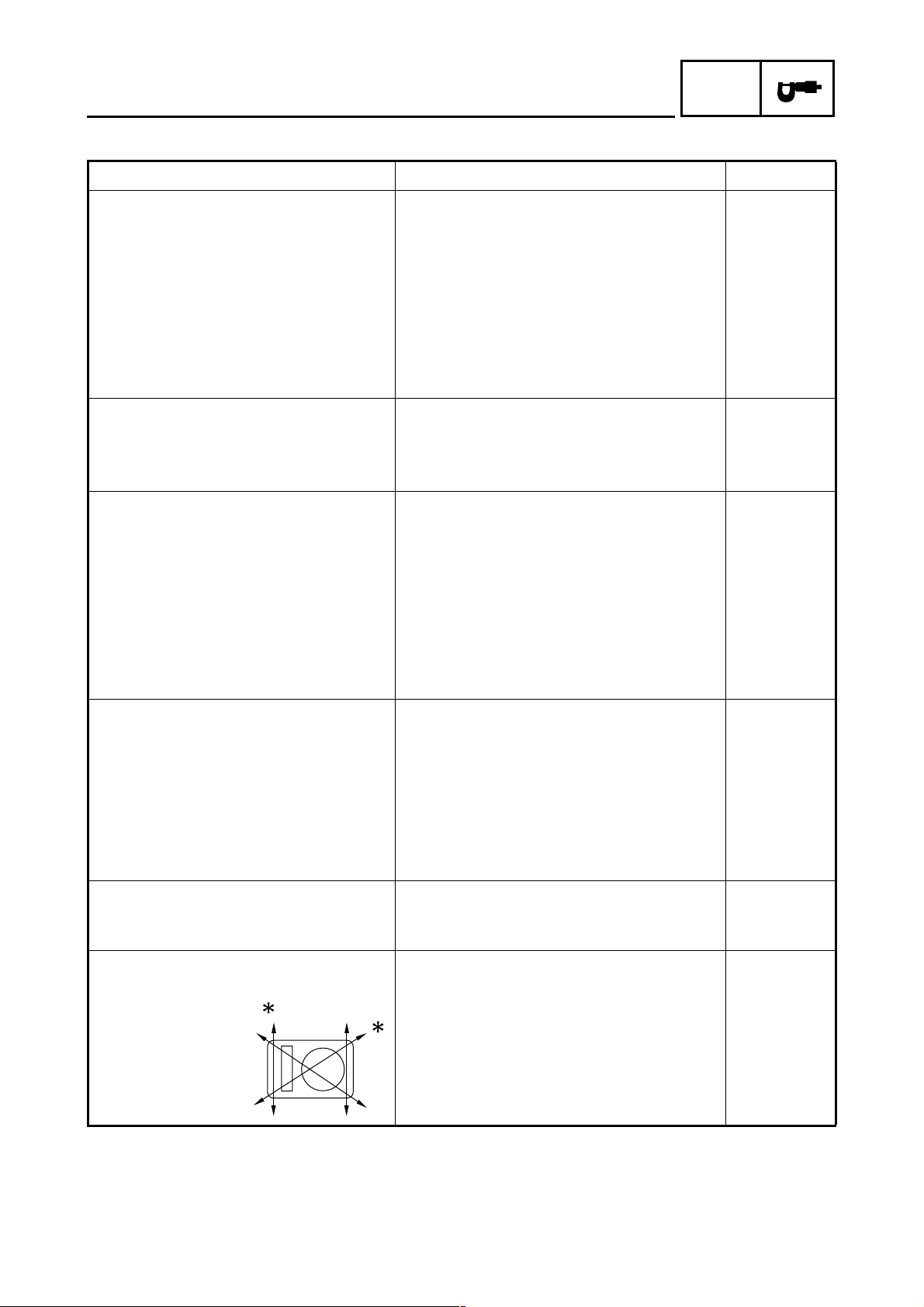
Þ Black
ß Cut off the excess end of the plastic locking tie to
2 mm or less, and then face the end of the tie
inward and upward in the range shown in the
illustration.
À Be sure to fasten the rear turn signal light lead
(left) on its protective sleeve with the plastic
locking tie.
Á The wire harness should not protrude past the
lines shown in the illustration.
Ù
Õ
Ø
CABLE ROUTING
1
2
3
È
SPEC
Ú
A-A
×
Ô
Í
Ö
Ò
Ñ
Ð
Ï
Õ
0
9
A
Î
É
Û
4
Ó
DD
B
A
Ë
C
C
Ê
5
9
Þ
À
Ý
Ü
B
ß
7
8
C-C
Á
Ì
8
A
2 - 35
7
6
D-D
Page 52

CHK
CHAPTER 3
PERIODIC CHECKS AND ADJUSTMENTS
ADJ
INTRODUCTION
PERIODIC MAINTENANCE AND LUBRICATION CHART
SIDE COVERS, SEAT AND FUEL TANK
BATTERY AND BATTERY BOX
ENGINE
...........................................................................................................3-7
ADJUSTING THE VALVE CLEARANCE ..................................................3-7
CHECKING AND ADJUSTING THE EXHAUST GAS...............................3-9
ADJUSTING THE ENGINE IDLING SPEED ...........................................3-11
ADJUSTING THE THROTTLE CABLE FREE PLAY ..............................3-12
CHECKING THE SPARK PLUG .............................................................3-14
CHECKING THE IGNITION TIMING.......................................................3-15
MEASURING THE COMPRESSION PRESSURE.................................. 3-16
CHECKING THE ENGINE OIL LEVEL.................................................... 3-17
CHANGING THE ENGINE OIL ...............................................................3-19
ADJUSTING THE CLUTCH CABLE FREE PLAY...................................3-20
CLEANING THE AIR FILTER ELEMENTS .............................................3-21
CHECKING THE CARBURETOR JOINT AND INTAKE MANIFOLD...... 3-23
CHECKING THE FUEL HOSE AND FUEL COCK FILTER ....................3-24
CHECKING THE CRANKCASE BREATHER HOSE ..............................3-24
CHECKING THE EXHAUST SYSTEM.................................................... 3-25
..............................................................................................3-1
............................3-1
.......................................................3-3
.....................................................................3-5
CHASSIS
ADJUSTING THE REAR BRAKE............................................................3-26
CHECKING THE BRAKE FLUID LEVEL.................................................3-26
CHECKING THE FRONT BRAKE PADS ................................................3-27
CHECKING THE REAR BRAKE SHOES................................................ 3-28
ADJUSTING THE REAR BRAKE LIGHT SWITCH .................................3-28
CHECKING THE FRONT BRAKE HOSE................................................ 3-29
BLEEDING THE HYDRAULIC BRAKE SYSTEM ...................................3-30
ADJUSTING THE DRIVE CHAIN SLACK ...............................................3-31
LUBRICATING THE DRIVE CHAIN ........................................................3-33
CHECKING AND ADJUSTING THE STEERING HEAD .........................3-34
CHECKING THE FRONT FORK .............................................................3-35
ADJUSTING THE REAR SHOCK ABSORBER ASSEMBLIES ..............3-36
CHECKING THE TIRES..........................................................................3-37
CHECKING THE WHEELS .....................................................................3-40
CHECKING AND LUBRICATING THE CABLES ....................................3-40
LUBRICATING THE LEVERS AND PEDALS ......................................... 3-41
LUBRICATING THE CENTERSTAND .................................................... 3-41
.......................................................................................................3-26
Page 53

CHK
ADJ
ELECTRICAL SYSTEM.................................................................................3-42
CHECKING AND CHARGING THE BATTERY.......................................3-42
CHECKING THE FUSE...........................................................................3-46
REPLACING THE HEADLIGHT BULB....................................................3-47
ADJUSTING THE HEADLIGHT BEAM ................................................... 3-48
Page 54

INTRODUCTION/
PERIODIC MAINTENANCE AND LUBRICATION CHART
EAS00036
CHK
ADJ
PERIODIC CHECKS AND ADJUSTMENTS
INTRODUCTION
This chapter includes all information necessary to perform recommended checks and adjustments.
If followed, these preventive maintenance procedures will ensure more reliable vehicle operation, a
longer service life and reduce the need for costly overhaul work. This information applies to vehicles
already in service as well as to new vehicles that are being prepared for sale. All service technicians
should be familiar with this entire chapter.
PERIODIC MAINTENANCE AND LUBRICATION CHART
NOTE:
• The annual checks must be performed every year, except if a kilometer-based maintenance
is performed instead.
• From 30000 km, repeat the maintenance intervals starting from 6000 km.
• Items marked with an asterisk should be performed by a Yamaha dealer as they require special
tools, data and technical skills.
NO. ITEM CHECK OR MAINTENANCE JOB
Fuel line
1*
(See page 3-24.)
Fuel cock filter
2*
(See page 3-24.)
Spark plug
3
(See page 3-14.)
Valves
4*
(See page 3-7.)
Air filter element
5
(See page 3-21.)
Battery
6*
(See page 3-42.)
Clutch
7
(See page 3-20.)
Front brake
8*
(See pages 3-26,
3-27.)
Rear brake
9*
(See pages 3-26,
3-28.)
Brake hose
10 *
(See page 3-29.)
Wheels
11 *
(See pages 4-3,
4-12.)
Tires
12 *
(See page 3-37.)
Wheel bearings
13 *
(See page 4-3.)
• Check fuel hoses for cracks or damage.
• Check condition.
• Check condition.
• Clean and regap.
• Replace.
• Check valve clearance.
• Adjust.
• Clean.
• Replace.
• Check electrolyte level and specific gravity.
• Make sure that the breather hose is properly
routed.
• Check operation.
• Adjust.
• Check operation, fluid level and vehicle for fluid
leakage.
• Replace brake pads.
• Check operation and adjust brake pedal free
play.
• Replace brake shoes.
• Check for cracks or damage.
• Replace.
• Check runout and for damage.
• Check tread depth and for damage.
• Replace if necessary.
• Check air pressure.
• Correct if necessary.
• Check bearing for looseness or damage.
ODOMETER READING (× 1000 km)
1 6 12 18 24
√√√√ √
√√
√√
√√
√√√√
√√
√√
√√√√ √
√√√√√
√√√√√ √
Whenever worn to the limit
√√√√√ √
Whenever worn to the limit
√√√√ √
Every 4 years
√√√√
√√√√ √
√√√√
ANNUAL
CHECK
3 - 1
Page 55

PERIODIC MAINTENANCE AND LUBRICATION CHART
CHK
ADJ
NO. ITEM CHECK OR MAINTENANCE JOB
Swingarm
14 *
(See page 4-67.)
Drive chain
15
(See pages 3-31,
4-61.)
Steering bearings
16 *
(See page 3-34.)
Chassis fasteners
17 *
(See page 2-19.)
Centerstand
18
(See page 3-41.)
Front fork
19 *
(See page 3-35.)
Shock absorber
20 *
assemblies
(See page 4-68.)
Carburetor
21 *
(See page 3-11.)
Engine oil
22
(See pages 3-17,
3-19.)
Front and rear
23 *
brake switches
(See page 7-3.)
Moving parts and
cables
24
(See pages 3-40,
3-41.)
Throttle grip hous-
25 *
ing and cable
(See page 3-12.)
Air induction sys-
26 *
tem
(See page 6-12.)
Lights, signals and
switches
27 *
(See pages 3-48,
7-3.)
• Check operation and for excessive play.
• Lubricate with lithium-soap-based grease.
• Check chain slack, alignment and condition.
• Adjust and lubricate chain with a special O-ring
chain lubricant thoroughly.
• Check bearing play and steering for roughness.
• Lubricate with lithium-soap-based grease.
• Make sure that all nuts, bolts and screws are
properly tightened.
• Check operation.
• Lubricate.
• Check operation and for oil leakage.
• Check operation and shock absorbers for oil leak-
age.
• Check starter (choke) operation.
• Adjust engine idling speed.
• Change.
• Check oil level and vehicle for oil leakage.
• Check operation.
• Lubricate.
• Check operation and free play.
• Adjust the throttle cable free play if necessary.
• Lubricate the throttle grip housing and cable.
• Check the air cut-off valve, reed valve, and hose
for damage.
• Replace any damaged parts if necessary.
• Check operation.
• Adjust headlight beam.
ODOMETER READING (× 1000 km)
1 6 12 18 24
√√√√
Every 24000 km
Every 1000 km and after washing the vehicle or
riding in the rain
√√√√√
Every 24000 km
√√√√ √
√√√√ √
√√√√
√√√√
√√√√√ √
√√√√√ √
√√√√√ √
√√√√ √
√√√√ √
√√√√ √
√√√√√ √
ANNUAL
CHECK
NOTE:
●
The air filter needs more frequent service if you are riding in unusually wet or dusty areas.
●
Hydraulic brake service
• Regularly check and, if necessary, correct the brake fluid level.
• Every two years replace the internal components of the brake master cylinder and caliper, and
change the brake fluid.
• Replace the brake hoses every four years and if cracked or damaged.
3 - 2
Page 56

SIDE COVERS, SEAT AND FUEL TANK
EAS00042
SIDE COVERS, SEAT AND FUEL TANK
CHK
ADJ
10
14
T
16 Nm (1.6 m
.
R
.
•
kg, 11 ft
•
Ib)
T
30 Nm (3.0 m
.
R
.
3
•
kg, 22 ft
•
Ib)
4
13
12
7
11
8
6
9
2
5
Order Job/Part Q’ty Remarks
Removing the side covers, seat and
Remove the parts in the order listed.
fuel tank
1 Left side cover 1
2 Right side cover 1
3 Seat 1
4 Carrier 1
5 Rear cowling assembly 1
6 Left rear side cover 1
7 Right rear side cover 1
8 Rear panel 1
9 Left air duct 1
10 Right air duct 1
11 Air duct stay 1
1
3 - 3
Page 57

SIDE COVERS, SEAT AND FUEL TANK
CHK
ADJ
10
14
T
16 Nm (1.6 m
.
R
.
•
kg, 11 ft
•
Ib)
T
30 Nm (3.0 m
.
R
.
3
•
kg, 22 ft
•
Ib)
4
13
12
7
11
8
6
9
2
5
Order Job/Part Q’ty Remarks
12 Fuel hose (fuel cock side) 1
NOTE:
Before disconnecting the fuel hose, turn
the fuel cock to “OFF”.
13 Fuel sender coupler 1 Disconnect.
14 Fuel tank 1
For installation, reverse the removal procedure.
1
3 - 4
Page 58

BATTERY AND BATTERY BOX
BATTERY AND BATTERY BOX
CHK
ADJ
13
11
8
12
10
3
9
2
4
14
14
6
5
1
15
T
7 Nm (0.7 m
.
R
.
•
kg, 5.1 ft
•
Ib)
Order Job/Part Q’ty Remarks
Removing the battery and battery
Remove the parts in the order listed.
box
Left side cover Refer to “SIDE COVERS, SEAT AND
FUEL TANK”.
1 Battery band 1
2 Negative battery lead 1 Disconnect.
3 Negative lead connector 1 Disconnect.
4 Positive battery lead 1
5 Battery breather hose 1 Disconnect.
6 Battery 1
7 Starter motor lead 1 Disconnect.
8 Starter relay coupler 1 Disconnect.
9 Starter relay 1
10 Turn signal relay coupler 1 Disconnect.
11 Turn signal relay 1
7
3 - 5
Page 59

BATTERY AND BATTERY BOX
8
11
CHK
ADJ
13
12
10
3
9
2
4
14
14
6
5
1
15
T
7 Nm (0.7 m
.
R
.
•
kg, 5.1 ft
•
Ib)
Order Job/Part Q’ty Remarks
12 Headlight relay coupler 1 Disconnect.
13 Headlight relay 1
14 Air vent hose 2
15 Battery box 1
For installation, reverse the removal pro-
cedure.
7
3 - 6
Page 60

ADJUSTING THE VALVE CLEARANCE
EAS00049
ENGINE
ADJUSTING THE VALVE CLEARANCE
The following procedure applies to all of the
valves.
NOTE:
_
• Valve clearance adjustment should be made
on a cold engine, at room temperature.
• When the valve clearance is to be measured
or adjusted, the piston must be at top dead
center (TDC) on the compression stroke.
1. Disconnect:
• spark plug cap
2. Remove:
• spark plug
CHK
ADJ
3. Remove:
• intake tappet cover
• exhaust tappet cover
• camshaft sprocket cover
4. Remove:
• timing mark accessing screw
• crankshaft end accessing screw
5. Measure:
• valve clearance
Out of specification → Adjust.
Valve clearance (cold)
Intake valve
0.08 ~ 0.12 mm
(0.0031 ~ 0.0047 in)
Exhaust valve
0.10 ~ 0.14 mm
(0.0039 ~ 0.0055 in)
1
2
3
1
2
3 - 7
Page 61

ADJUSTING THE VALVE CLEARANCE
▼▼▼▼ ▼ ▼▼▼▼ ▼ ▼▼▼▼ ▼ ▼▼▼▼ ▼ ▼▼▼▼ ▼ ▼▼▼▼ ▼▼▼
a. Turn the crankshaft counterclockwise.
b. When the piston is at TDC on the compres-
sion stroke, align the “I” mark a on the A.C.
magneto rotor with the stationary b on the
A.C. magneto rotor cover.
c. Align the “I” mark c on the camshaft
sprocket with the stationary pointer d on
the cylinder head.
d. Measure the valve clearance with a thick-
ness gauge 1.
Thickness gauge
90890-03079, YM-34483
Out of specification → Adjust.
▲▲▲▲ ▲ ▲▲▲▲ ▲ ▲▲▲▲ ▲ ▲▲▲▲ ▲ ▲▲▲▲ ▲ ▲▲▲▲ ▲▲▲
CHK
ADJ
6. Adjust:
• valve clearance
▼▼▼▼ ▼ ▼▼▼▼ ▼ ▼▼▼▼ ▼ ▼▼▼▼ ▼ ▼▼▼▼ ▼ ▼▼▼▼ ▼▼▼
a. Loosen the locknut 1.
b. Insert a thickness gauge 2 between the
end of the adjusting screw and the valve tip.
c. Turn the adjusting screw 3 in direction a
or b until the specified valve clearance is
obtained.
Direction
Direction b
a
Tappet adjusting tool
90890-01311, YM-08035-A
Valve clearance is
increased.
Valve clearance is
decreased.
3 - 8
Page 62

ADJUSTING THE VALVE CLEARANCE/
CHECKING AND ADJUSTING THE EXHAUST GAS
• Hold the adjusting screw to prevent it from
moving and tighten the locknut to specification.
Locknut
8 Nm (0.8 m · kg, 5.8 ft · lb)
T
.
R
.
d. Measure the valve clearance again.
e. If the valve clearance is still out of specifica-
tion, repeat all of the valve clearance adjustment steps until the specified clearance is
obtained.
▲▲▲▲ ▲ ▲▲▲▲ ▲ ▲▲▲▲ ▲ ▲▲▲▲ ▲ ▲▲▲▲ ▲ ▲▲▲▲ ▲▲▲
7. Install:
• timing mark accessing screw
• crankshaft end accessing screw
8. Install:
• O-rings
• camshaft sprocket cover
• intake tappet cover
• exhaust tappet cover
9. Install:
• spark plug
10.Connect:
• spark plug cap
New
T
10 Nm (1.0 m · kg, 7.2 ft · lb)
.
R
.
T
18 Nm (1.8 m · kg, 13 ft · lb)
.
R
.
T
18 Nm (1.8 m · kg, 13 ft · lb)
.
R
.
T
13 Nm (1.3 m · kg, 9.4 ft · lb)
.
R
.
CHK
ADJ
1
EAS00868
CHECKING AND ADJUSTING THE
EXHAUST GAS
1. Stand the vehicle on a level surface.
NOTE:
_
• Place the vehicle on a suitable stand.
• Make sure the vehicle is upright.
• Measure the exhaust gas at idle when the air
induction system is not operating.
2. Install:
• temperature probe tester 1
(onto the engine oil drain bolt)
3 - 9
Page 63

CHECKING AND ADJUSTING THE EXHAUST GAS
3. Disconnect:
• air induction system hose
(air cut-off valve to cylinder head) 1
4. Stop air induction system operation.
CHK
ADJ
1
NOTE:
Crimp the hose 1 running from the reed valve
to the air cut-off valve to prevent the air cut-off
valve from operating.
Make sure not to damage the hose while
crimping it.
5. Start the engine and warm it up until the
specified oil temperature is reached.
Oil temperature
75 ~ 85 °C (167 ~ 185 °F)
6. Measure:
• engine idling speed
(air induction system OFF)
Out of specification → Adjust.
Refer to “ADJUSTING THE ENGINE
IDLING SPEED”.
Engine idling speed
1,350 ~ 1,450 r/min
3 - 10
7. Install:
• CO tester 1
• sampling probe 2
NOTE:
• Be sure to set the heat-resistant rubber tube
so that exhaust gas does not leak out.
• Before using the CO tester, be sure to read
the user’s manual.
Page 64

CHECKING AND ADJUSTING THE EXHAUST GAS/
ADJUSTING THE ENGINE IDLING SPEED
8. Measure:
• CO density
Out of specification → Adjust.
Within specification → Check the air induction system.
Refer to “AIR INDUCTION SYSTEM” in
chapter 6.
CO density (when the air induction system is not operating)
3.0 ~ 5.0%
CHK
ADJ
1
9. Adjust:
• pilot screw 1
Pilot screw
1-1/2 turns out
If the CO density cannot be adjusted with the
pilot screw, overhaul the carburetor and check
the air filter.
EAS00054
ADJUSTING THE ENGINE IDLING SPEED
NOTE:
_
Prior to adjusting the engine idling speed, the
air filter element should be clean, and the
engine should have adequate compression.
1. Start the engine and let it warm up for sev-
eral minutes.
2. Check:
• engine idling speed
(air induction system ON)
Out of specification → Adjust.
3 - 11
Engine idling speed
1,400 ~ 1,500 r/min
Page 65

ADJUSTING THE ENGINE IDLING SPEED/
ADJUSTING THE THROTTLE CABLE FREE PLAY
3. Adjust:
• engine idling speed
CHK
ADJ
3
2
b
b
a
a
1
▼▼▼▼ ▼ ▼▼▼▼ ▼ ▼▼▼▼ ▼ ▼▼▼▼ ▼ ▼▼▼▼ ▼ ▼▼▼▼ ▼▼▼
a. Turn the pilot screw 1 in or out until it is
lightly seated with the carburetor angle
driver 2.
Carburetor angle driver
90890-03158
b. Turn the pilot screw out the specified num-
ber of turns.
Pilot screw setting
1-1/2 turns out
c. Turn the throttle stop screw 3 in direction
a or b until the specified engine idling
speed is obtained.
Direction
Direction b
a
Engine idling speed is
increased.
Engine idling speed is
decreased.
a
▲▲▲▲ ▲ ▲▲▲▲ ▲ ▲▲▲▲ ▲ ▲▲▲▲ ▲ ▲▲▲▲ ▲ ▲▲▲▲ ▲▲▲
4. Adjust:
• throttle cable free play
Refer to “ADJUSTING THE THROTTLE
CABLE FREE PLAY”.
Throttle cable free play (at the
flange of the throttle grip)
3 ~ 7 mm (0.12 ~ 0.28 in)
EAS00058
ADJUSTING THE THROTTLE CABLE FREE
PLAY
NOTE:
_
Prior to adjusting the throttle cable free play,
the engine idling speed should be adjusted.
1. Check:
• throttle cable free play a
Out of specification → Adjust.
3 - 12
Throttle cable free play (at the
flange of the throttle grip)
3 ~ 7 mm (0.12 ~ 0.28 in)
Page 66

ADJUSTING THE THROTTLE CABLE FREE PLAY
2. Adjust:
1
3
bab
2
• throttle cable free play
▼▼▼▼ ▼ ▼▼▼▼ ▼ ▼▼▼▼ ▼ ▼▼▼▼ ▼ ▼▼▼▼ ▼ ▼▼▼▼ ▼▼▼
Carburetor side
a. Slide back the rubber cover 1.
b. Loosen the locknut 2.
c. Turn the adjusting nut 3 in direction a or
b until the specified throttle cable free play
is obtained.
CHK
ADJ
a
(a)
b
1
3
2
Direction
Direction
a
b
Throttle cable free play
is increased.
Throttle cable free play
is decreased.
d. Tighten the locknut.
e. Slide the rubber cover to its original posi-
tion.
NOTE:
_
If the specified throttle cable free play cannot
be obtained on the carburetor side of the
cable, use the adjusting nut on the handlebar
side.
Handlebar side
a. Slide back the rubber cover 1.
b. Loosen the locknut 2.
c. Turn the adjusting nut 3 in direction a or
b until the specified throttle cable free play
is obtained.
3 - 13
Direction
a
Direction b
Throttle cable free play
is increased.
Throttle cable free play
is decreased.
d. Tighten the locknut.
e. Slide the rubber cover to its original posi-
tion.
WARNING
_
After adjusting the throttle cable free play,
start the engine and turn the handlebar to
the right or left to ensure that this does not
cause the engine idling speed to change.
▲▲▲▲ ▲ ▲▲▲▲ ▲ ▲▲▲▲ ▲ ▲▲▲▲ ▲ ▲▲▲▲ ▲ ▲▲▲▲ ▲▲▲
Page 67

CHECKING THE SPARK PLUG
EAS00060
CHECKING THE SPARK PLUG
1. Disconnect:
• spark plug cap
2. Remove:
• spark plug
CAUTION:
_
Before removing the spark plug, blow away
any dirt accumulated in the spark plug well
with compressed air to prevent it from falling into the cylinder.
3. Check:
• spark plug type
Incorrect → Change.
Spark plug type (manufacturer)
CR6HSA (NGK)
CHK
ADJ
4. Check:
• electrode 1
Damage/wear → Replace the spark plug.
• insulator 2
Abnormal color → Replace the spark plug.
Normal color is medium-to-light tan.
5. Clean:
• spark plug
(with a spark plug cleaner or wire brush)
6. Measure:
• spark plug gap a
(with a wire thickness gauge)
Out of specification → Regap.
Spark plug gap
0.6 ~ 0.7 mm (0.024 ~ 0.028 in)
7. Install:
• spark plug
NOTE:
_
T
13 Nm (1.3 m · kg, 9.4 ft · lb)
.
R
.
Before installing the spark plug, clean the
spark plug and gasket surface.
3 - 14
8. Connect:
• spark plug cap
Page 68

CHECKING THE IGNITION TIMING
EAS00064
CHECKING THE IGNITION TIMING
NOTE:
_
Prior to checking the ignition timing, check the
wiring connections of the entire ignition system. Make sure all connections are tight and
free of corrosion.
1. Remove:
• timing mark accessing screw
2. Connect:
• timing light 1
(onto the spark plug lead)
Timing light
90890-03141, YU-03141
CHK
ADJ
3. Check:
• ignition timing
▼▼▼▼ ▼ ▼▼▼▼ ▼ ▼▼▼▼ ▼ ▼▼▼▼ ▼ ▼▼▼▼ ▼ ▼▼▼▼ ▼▼▼
a. Start the engine, warm it up for several min-
utes, and then let it run at the specified
engine idling speed.
Engine idling speed
1,400 ~ 1,500 r/min
b. Check that the stationary pointer a is within
the firing range b on the A.C. magneto
rotor.
Incorrect firing range → Check the ignition
system.
NOTE:
_
The ignition timing is not adjustable.
▲▲▲▲ ▲ ▲▲▲▲ ▲ ▲▲▲▲ ▲ ▲▲▲▲ ▲ ▲▲▲▲ ▲ ▲▲▲▲ ▲▲▲
4. Disconnect:
• timing light
5. Install:
• timing mark accessing screw
3 - 15
Page 69

MEASURING THE COMPRESSION PRESSURE
EAS00067
MEASURING THE COMPRESSION
PRESSURE
NOTE:
_
Insufficient compression pressure will result in
a loss of performance.
1. Measure:
• valve clearance
Out of specification → Adjust.
Refer to “ADJUSTING THE VALVE
CLEARANCE”.
2. Start the engine, warm it up for several minutes, and then turn it off.
3. Disconnect:
• spark plug cap
4. Remove:
• spark plug
CHK
ADJ
CAUTION:
_
Before removing the spark plug, use compressed air to blow away any dirt accumulated in the spark plug well to prevent it
from falling into the cylinder.
5. Install:
• compression gauge
1
Compression gauge
90890-03081, YU-33223
6. Measure:
• compression pressure
Out of specification → Refer to steps (c)
and (d).
Compression pressure (at sea
level)
Minimum
1,044 kPa
2
(10.4 kg/cm
, 148.5 psi)
Standard
1,200 kPa
2
(12.0 kg/cm
, 170.7 psi)
Maximum
1,344 kPa
2
(13.4 kg/cm
, 191.2 psi)
3 - 16
Page 70

MEASURING THE COMPRESSION PRESSURE/
CHECKING THE ENGINE OIL LEVEL
▼▼▼▼ ▼ ▼▼▼▼ ▼ ▼▼▼▼ ▼ ▼▼▼▼ ▼ ▼▼▼▼ ▼ ▼▼▼▼ ▼▼▼
a. Set the main switch to “ON”.
b. With the throttle wide open, crank the
engine until the reading on the compression
gauge stabilizes.
WARNING
_
To prevent sparking, ground the spark plug
lead before cranking the engine.
c. If the compression pressure is above the
maximum specification, check the cylinder
head, valve surfaces, and piston crown for
carbon deposits.
Carbon deposits → Eliminate.
d. If the compression pressure is below the
minimum specification, pour a teaspoonful
engine of oil into the spark plug bore and
measure again.
Refer to the following table.
CHK
ADJ
Compression pressure
(with oil applied into the cylinder)
Reading Diagnosis
Higher than without oil
Piston ring(s), piston wear or damage → Repair.
Valves, cylinder
Same as without
oil
head gasket or pis-
ton possibly defec-
tive → Repair.
▲▲▲▲ ▲ ▲▲▲▲ ▲ ▲▲▲▲ ▲ ▲▲▲▲ ▲ ▲▲▲▲ ▲ ▲▲▲▲ ▲▲▲
7. Install:
• spark plug
T
13 Nm (1.3 m · kg, 9.4 ft · lb)
.
R
.
8. Connect:
• spark plug cap
EAS00069
CHECKING THE ENGINE OIL LEVEL
1. Stand the vehicle on a level surface.
3 - 17
NOTE:
_
• Place the vehicle on a suitable stand.
• Make sure the vehicle is upright.
2. Start the engine, warm it up for several minutes, and then turn it off.
Page 71

-20 -10 0
SAE 10W-30
10
CHECKING THE ENGINE OIL LEVEL
3. Check:
• engine oil level
The engine oil level should be between the
minimum level mark a and maximum level
mark b.
Below the minimum level mark → Add the
recommended engine oil to the proper level.
NOTE:
_
• Before checking the engine oil level, wait a
few minutes until the oil has settled.
20 30
40
50 ˚C
• Do not screw the dipstick 1 in when check-
ing the oil level.
CHK
ADJ
SAE 10W-40
SAE 15W-40
SAE 20W-40
SAE 20W-50
Recommended oil
Refer to the chart for the engine
oil grade which is best suited
for certain atmospheric temperatures.
API standard
SE or higher grade
CAUTION:
_
• Engine oil also lubricates the clutch and
the wrong oil types or additives could
cause clutch slippage. Therefore, do not
add any chemical additives or use engine
oils with a grade of CD c or higher and
do not use oils labeled “ENERGY CONSERVING II” d or higher.
• Do not allow foreign materials to enter the
crankcase.
NOTE:
_
Before checking the engine oil level, wait a few
minutes until the oil has settled.
3 - 18
4. Start the engine, warm it up for several min-
utes, and then turn it off.
5. Check the engine oil level again.
NOTE:
_
Before checking the engine oil level, wait a few
minutes until the oil has settled.
Page 72

CHANGING THE ENGINE OIL
EAS00076
CHANGING THE ENGINE OIL
1. Start the engine, warm it up for several min-
utes, and then turn it off.
2. Place a container under the engine oil drain
bolt.
3. Remove:
• engine oil filler cap 1
• engine oil drain bolt 2
(along with the gasket)
4. Drain:
• engine oil
(completely from the crankcase)
5. Check:
• engine oil drain bolt gasket
Damage → Replace.
6. Install:
• engine oil drain bolt
(along with the gasket)
T
20 Nm (2.0 m · kg, 14 ft · lb)
.
R
.
7. Fill:
• crankcase
(with the specified amount of the recommended engine oil)
CHK
ADJ
Quantity
Total amount
1.20 L (1.06 Imp qt, 1.27 US qt)
Periodic oil change
1.00 L (0.88 Imp qt, 1.06 US qt)
8. Install:
• engine oil filler cap
9. Start the engine, warm it up for several minutes, and then turn it off.
10.Check:
• engine
(for engine oil leaks)
11.Check:
• engine oil level
Refer to “CHECKING THE ENGINE OIL
LEVEL”.
3 - 19
Page 73

CHANGING THE ENGINE OIL/
ADJUSTING THE CLUTCH CABLE FREE PLAY
12.Check:
• engine oil pressure
▼▼▼▼ ▼ ▼▼▼▼ ▼ ▼▼▼▼ ▼ ▼▼▼▼ ▼ ▼▼▼▼ ▼ ▼▼▼▼ ▼▼▼
a. Slightly loosen the oil gallery bolt 1.
b. Start the engine and keep it idling until
engine oil starts to seep from the oil gallery
bolt. If no engine oil comes out after one
minute, turn the engine off so that it will not
seize.
c. Check the engine oil passages and the oil
pump for damage or leakage. Refer to “OIL
PUMP” in chapter 5.
d. Start the engine after solving the problem(s)
and check the engine oil pressure again.
e. Tighten the oil gallery bolt to specification.
Oil gallery bolt
7 Nm (0.7 m · kg, 5.1 ft · lb)
T
.
R
.
CHK
ADJ
a
1
2
3
b
c
b
▲▲▲▲ ▲ ▲▲▲▲ ▲ ▲▲▲▲ ▲ ▲▲▲▲ ▲ ▲▲▲▲ ▲ ▲▲▲▲ ▲▲▲
EAS00078
ADJUSTING THE CLUTCH CABLE FREE
PLAY
1. Check:
• clutch cable free play a
Out of specification → Adjust.
Clutch cable free play (at the end
of the clutch lever)
10 ~ 15 mm (0.39 ~ 0.59 in)
2. Adjust:
• clutch cable free play
▼▼▼▼ ▼ ▼▼▼▼ ▼ ▼▼▼▼ ▼ ▼▼▼▼ ▼ ▼▼▼▼ ▼ ▼▼▼▼ ▼▼▼
Handlebar side
a. Slide back the rubber cover 1.
b. Loosen the locknut 2.
c. Turn the adjusting bolt 3 in direction b or
c until the specified clutch cable free play
is obtained.
3 - 20
Direction
Direction
b
c
Clutch cable free play is
increased.
Clutch cable free play is
decreased.
Page 74

ADJUSTING THE CLUTCH CABLE FREE PLAY/
CLEANING THE AIR FILTER ELEMENTS
d. Tighten the locknut.
e. Slide the rubber cover to its original posi-
tion.
NOTE:
_
If the specified clutch cable free play cannot be
obtained on the handlebar side of the cable,
use the adjusting nut on the engine side.
Engine side
a. Slide back the rubber cover 1.
b. Loosen the locknut 2.
1
b
c. Turn the adjusting bolt 3 in direction a or
b until the specified clutch cable free play
is obtained.
CHK
ADJ
a
3
2
Direction
Direction
d. Tighten the locknut.
e. Slide the rubber cover to its original posi-
tion.
▲▲▲▲ ▲ ▲▲▲▲ ▲ ▲▲▲▲ ▲ ▲▲▲▲ ▲ ▲▲▲▲ ▲ ▲▲▲▲ ▲▲▲
EAS00086
CLEANING THE AIR FILTER ELEMENTS
NOTE:
There is a check hose 1 at the bottom of the
air filter case. If dust and/or water collects in
this hose, clean the air filter elements and air
filter case.
a
b
Clutch cable free play is
increased.
Clutch cable free play is
decreased.
1
1. Remove:
• right side cover
Refer to “SIDE COVERS, SEAT AND FUEL
TANK”.
3 - 21
Page 75

1
CLEANING THE AIR FILTER ELEMENTS
2. Remove:
• air filter case cover 1
• air filter element 1
• air filter element 2
3. Check:
2
1
• air filter element 1 1
• air filter element 2 2
Damage → Replace.
CHK
ADJ
1
4. Clean:
• air filter element 2 1
Apply compressed air to the outer surface
of the air filter element 2.
5. Clean:
• air filter element 1
▼▼▼▼ ▼ ▼▼▼▼ ▼ ▼▼▼▼ ▼ ▼▼▼▼ ▼ ▼▼▼▼ ▼ ▼▼▼▼ ▼▼▼
a. Wash the element gently, but thoroughly in
solvent.
WARNING
Use a cleaning solvent which is designed
to clean parts only. Never use gasoline or
low flash point solvents as they may cause
a fire or explosion.
3 - 22
b. Squeeze the excess solvent out of the ele-
ment and let it dry.
CAUTION:
Do not twist or wring out the element. This
could damage the foam material.
▲▲▲▲ ▲ ▲▲▲▲ ▲ ▲▲▲▲ ▲ ▲▲▲▲ ▲ ▲▲▲▲ ▲ ▲▲▲▲ ▲▲▲
Page 76

CLEANING THE AIR FILTER ELEMENTS/
CHECKING THE CARBURETOR JOINT AND INTAKE MANIFOLD
6. Install:
• air filter element 2
• air filter element 1
• air filter case cover
CAUTION:
_
Never operate the engine without the air filter element installed. Unfiltered air will
cause rapid wear of engine parts and may
damage the engine. Operating the engine
without the air filter element will also affect
the carburetor tuning, leading to poor
engine performance and possible overheating.
NOTE:
_
When installing the air filter element into the air
filter case cover, make sure their sealing surfaces are aligned to prevent any air leaks.
CHK
ADJ
3
1
2
7. Install:
• right side cover
Refer to “SIDE COVERS, SEAT AND FUEL
TANK”.
EAS00094
CHECKING THE CARBURETOR JOINT AND
INTAKE MANIFOLD
1. Remove:
• side cover (left and right)
Refer to “SIDE COVERS, SEAT AND FUEL
TANK”.
2. Check:
• carburetor joint (intake manifold side) 1
• intake manifold 2
• carburetor joint (air filter case side) 3
Cracks/damage → Replace.
Refer to “CARBURETOR” in chapter 6.
3. Install:
• side cover (left and right)
Refer to “SIDE COVERS, SEAT AND FUEL
TANK”.
3 - 23
Page 77

CHECKING THE FUEL HOSE AND FUEL COCK FILTER/
CHECKING THE CRANKCASE BREATHER HOSE
EAS00097
CHECKING THE FUEL HOSE AND FUEL
COCK FILTER
1. Remove:
• left air duct
Refer to “SIDE COVERS, SEAT AND FUEL
TANK”.
2. Check:
2
1
T
3 Nm (0.3 m · kg, 2.2 ft · lb)
.
R
.
• fuel hose
Cracks/damage → Replace.
• fuel filter
Contaminants/damage → Replace the cock
13
assembly.
▼▼▼▼ ▼ ▼▼▼▼ ▼ ▼▼▼▼ ▼ ▼▼▼▼ ▼ ▼▼▼▼ ▼ ▼▼▼▼ ▼▼▼
a. Turn the fuel cock to the “OFF”.
b. Remove the fuel cock filter cup 3.
c. Drain the fuel.
d. Checking the fuel cock filter.
e. Install the fuel cock filter cup.
▲▲▲▲ ▲ ▲▲▲▲ ▲ ▲▲▲▲ ▲ ▲▲▲▲ ▲ ▲▲▲▲ ▲ ▲▲▲▲ ▲▲▲
2
3. Install:
• left air duct
Refer to “SIDE COVERS, SEAT AND FUEL
TANK”.
CHK
ADJ
1
3 - 24
EAS00098
CHECKING THE CRANKCASE BREATHER
HOSE
1. Remove:
• right side cover
Refer to “SIDE COVERS, SEAT AND FUEL
TANK”.
2. Check:
• crankcase breather hose 1
Cracks/damage → Replace.
Loose connection → Connect properly.
CAUTION:
_
Make sure the crankcase breather hose is
routed correctly.
3. Install:
• right side cover
Refer to “SIDE COVERS, SEAT AND FUEL
TANK”.
Page 78

CHECKING THE EXHAUST SYSTEM
EAS00099
CHECKING THE EXHAUST SYSTEM
1. Check:
• muffler assembly
Cracks/damage → Replace.
• exhaust pipe gasket
Exhaust gas leaks → Replace.
2. Check:
• tightening torques
1
CHK
ADJ
2
Exhaust pipe bolts
10 Nm (1.0 m · kg, 7.2 ft · lb)
T
.
R
.
Muffler bolt
4
22 Nm (2.2 m · kg, 16 ft · lb)
3
3 - 25
Page 79

a
ADJUSTING THE REAR BRAKE/
CHECKING THE BRAKE FLUID LEVEL
CHASSIS
EAS00113
ADJUSTING THE REAR BRAKE
1. Check:
• brake pedal free play a
Out of specification → Adjust.
1
a
2. Adjust:
• brake pedal free play
▼▼▼▼ ▼ ▼▼▼▼ ▼ ▼▼▼▼ ▼ ▼▼▼▼ ▼ ▼▼▼▼ ▼ ▼▼▼▼ ▼▼▼
a. Turn the brake rod adjusting nut 1 in direc-
tion a or b until the specified brake pedal
free play is obtained.
Brake pedal free play (at the end
of the brake pedal)
20 ~ 30 mm (0.79 ~ 1.18 in)
CHK
ADJ
b
Direction
Direction
CAUTION:
_
a
b
Brake pedal free play is
increased.
Brake pedal free play is
decreased.
After adjusting the brake pedal free play,
make sure there is no brake drag.
▲▲▲▲ ▲ ▲▲▲▲ ▲ ▲▲▲▲ ▲ ▲▲▲▲ ▲ ▲▲▲▲ ▲ ▲▲▲▲ ▲▲▲
3. Adjust:
• rear brake light switch
Refer to “ADJUSTING THE REAR BRAKE
LIGHT SWITCH”.
3 - 26
EAS00115
CHECKING THE BRAKE FLUID LEVEL
1. Stand the vehicle on a level surface.
NOTE:
_
• Place the vehicle on a suitable stand.
• Make sure the vehicle is upright.
Page 80

a
CHECKING THE BRAKE FLUID LEVEL/
CHECKING THE FRONT BRAKE PADS
2. Check:
• brake fluid level
Below the minimum level mark a → Add
the recommended brake fluid to the proper
level.
Recommended brake fluid
DOT 3 or 4
WARNING
_
• Use only the designated brake fluid.
Other brake fluids may cause the rubber
seals to deteriorate, causing leakage and
poor brake performance.
• Refill with the same type of brake fluid
that is already in the system. Mixing
brake fluids may result in a harmful
chemical reaction, leading to poor brake
performance.
• When refilling, be careful that water does
not enter the brake fluid reservoir. Water
will significantly lower the boiling point of
the brake fluid and could cause vapor
lock.
CHK
ADJ
CAUTION:
_
Brake fluid may damage painted surfaces
and plastic parts. Therefore, always clean
up any spilt brake fluid immediately.
NOTE:
_
In order to ensure a correct reading of the
brake fluid level, make sure the top of the
brake fluid reservoir is horizontal.
EAS00117
CHECKING THE FRONT BRAKE PADS
The following procedure applies to all of the
brake pads.
1. Operate the brake.
3 - 27
Page 81

1
CHECKING THE FRONT BRAKE PADS/
CHECKING THE REAR BRAKE SHOES/
ADJUSTING THE REAR BRAKE LIGHT SWITCH
2. Remove:
• check plug 1
3. Check:
• front brake pad
Wear indicators 2 almost touch the brake
disc → Replace the brake pads as a set.
Refer to “REPLACING THE FRONT
2
BRAKE PADS” in chapter 4.
4. Install:
• check plug
CHK
ADJ
2
1
EAS00126
CHECKING THE REAR BRAKE SHOES
1. Operate the brake.
2. Check:
• wear indicator 1
Reaches the wear limit line 2 → Replace
the brake shoes as a set.
Refer to “REAR WHEEL, BRAKE SHOE
PLATE, AND REAR WHEEL SPROCKET”
in chapter 4.
EAS00128
ADJUSTING THE REAR BRAKE LIGHT
SWITCH
NOTE:
_
The rear brake light switch is operated by
movement of the brake pedal. The rear brake
light switch is properly adjusted when the
brake light comes on just before the braking
effect starts.
3 - 28
1. Remove:
• right side cover
Refer to “SIDE COVERS, SEAT AND FUEL
TANK”.
2. Check:
• rear brake light operation timing
Incorrect → Adjust.
Page 82

ADJUSTING THE REAR BRAKE LIGHT SWITCH/
CHECKING THE FRONT BRAKE HOSE
3. Adjust:
• rear brake light operation timing
▼▼▼▼ ▼ ▼▼▼▼ ▼ ▼▼▼▼ ▼ ▼▼▼▼ ▼ ▼▼▼▼ ▼ ▼▼▼▼ ▼▼▼
a. Hold the main body 1 of the rear brake light
switch so that it does not rotate and turn the
adjusting nut 2 in direction a or b until the
rear brake light comes on at the proper
time.
2
1
a
b
CHK
ADJ
Direction
Direction
▲▲▲▲ ▲ ▲▲▲▲ ▲ ▲▲▲▲ ▲ ▲▲▲▲ ▲ ▲▲▲▲ ▲ ▲▲▲▲ ▲▲▲
4. Install:
• right side cover
Refer to “SIDE COVERS, SEAT AND FUEL
TANK”.
EAS00129
CHECKING THE FRONT BRAKE HOSE
1. Check:
• brake hose
Cracks/damage/wear → Replace.
2. Check:
• brake hose clamp
Loose connection → Tighten the clamp bolt.
3. Hold the vehicle upright and apply the front
brake several times.
4. Check:
• brake hose
Brake fluid leakage → Replace the damaged hose.
Refer to “FRONT BRAKE” in chapter 4.
a
b
Brake light comes on
sooner.
Brake light comes on
later.
3 - 29
Page 83

BLEEDING THE HYDRAULIC BRAKE SYSTEM
EAS00133
BLEEDING THE HYDRAULIC BRAKE
SYSTEM
WARNING
_
Bleed the hydraulic brake system whenever:
• the system is disassembled.
• a brake hose is loosened, disconnected
or replaced.
• the brake fluid level is very low.
• brake operation is faulty.
NOTE:
_
• Be careful not to spill any brake fluid or allow
the brake master cylinder reservoir to overflow.
• When bleeding the hydraulic brake system,
make sure there is always enough brake
fluid before applying the brake. Ignoring this
precaution could allow air to enter the
hydraulic brake system, considerably lengthening the bleeding procedure.
• If bleeding is difficult, it may be necessary to
let the brake fluid settle for a few hours.
Repeat the bleeding procedure when the tiny
bubbles in the hose have disappeared.
CHK
ADJ
1
2
1. Bleed:
• hydraulic brake system
▼▼▼▼ ▼ ▼▼▼▼ ▼ ▼▼▼▼ ▼ ▼▼▼▼ ▼ ▼▼▼▼ ▼ ▼▼▼▼ ▼▼▼
a. Fill the brake fluid reservoir to the proper
level with the recommended brake fluid.
b. Install the brake master cylinder reservoir
diaphragm.
c. Connect a clear plastic hose 1 tightly to the
bleed screw 2.
d. Place the other end of the hose into a con-
tainer.
e. Slowly apply the brake lever several times.
f. Fully pull the brake lever without releasing
it.
3 - 30
Page 84

BLEEDING THE HYDRAULIC BRAKE SYSTEM/
ADJUSTING THE DRIVE CHAIN SLACK
g. Loosen the bleed screw.
NOTE:
_
Loosening the bleed screw will release the
pressure and cause the brake lever to contact
the throttle grip.
h. Tighten the bleed screw and then release
the brake lever.
i. Repeat steps (e) to (h) until all of the air
bubbles have disappeared from the brake
fluid in the plastic hose.
j. Tighten the bleed screw to specification.
Bleed screw
6 Nm (0.6 m · kg, 4.3 ft · lb)
T
.
R
.
k. Fill the brake fluid reservoir to the proper
level with the recommended brake fluid.
Refer to “CHECKING THE BRAKE FLUID
LEVEL”.
CHK
ADJ
WARNING
_
After bleeding the hydraulic brake system,
check the brake operation.
▲▲▲▲ ▲ ▲▲▲▲ ▲ ▲▲▲▲ ▲ ▲▲▲▲ ▲ ▲▲▲▲ ▲ ▲▲▲▲ ▲▲▲
EAS00140
ADJUSTING THE DRIVE CHAIN SLACK
NOTE:
_
The drive chain slack must be checked at the
tightest point on the chain.
CAUTION:
_
A drive chain that is too tight will overload
the engine and other vital parts, and one
that is too loose can skip and damage the
swingarm or cause an accident. Therefore,
keep the drive chain slack within the specified limits.
3 - 31
Page 85

ADJUSTING THE DRIVE CHAIN SLACK
1. Stand the vehicle on a level surface.
WARNING
_
Securely support the vehicle so that there
is no danger of it falling over.
NOTE:
_
Place the vehicle on a suitable stand so that
the rear wheel is elevated.
2. Spin the rear wheel several times and find
the tightest position of drive chain.
3. Check:
• drive chain slack a
Out of specification → Adjust.
CHK
ADJ
6
5
3
c
a
5
4
2
6
1
(b)
b
a
Drive chain slack
20 ~ 30 mm (0.79 ~ 1.18 in)
T
.
R
.
4. Adjust:
• drive chain slack
▼▼▼▼ ▼ ▼▼▼▼ ▼ ▼▼▼▼ ▼ ▼▼▼▼ ▼ ▼▼▼▼ ▼ ▼▼▼▼ ▼▼▼
a. Remove the cotter pin 1.
b. Loosen the brake torque rod nut 2.
c. Loosen the brake rod adjusting nut 3.
d. Loosen the wheel axle nut 4.
e. Loosen both chain puller locknuts 5.
f. Turn both chain puller adjusting bolts 6 in
direction a or b until the specified drive
chain slack is obtained.
Direction
Direction
NOTE:
_
a
b
Drive chain is tightened.
Drive chain is loosened.
To maintain the proper wheel alignment, adjust
both sides c evenly.
3 - 32
g. Tighten both chain puller locknuts to specifi-
cation.
Chain puller locknut
16 Nm (1.6 m · kg, 11 ft · lb)
T
.
R
.
Page 86

ADJUSTING THE DRIVE CHAIN SLACK/
LUBRICATING THE DRIVE CHAIN
h. Tighten the wheel axle nut to specification.
Wheel axle nut
91 Nm (9.1 m · kg, 66 ft · lb)
T
.
R
.
i. Tighten the brake torque rod nut to specifi-
cation.
Brake torque rod nut
19 Nm (1.9 m · kg, 13 ft · lb)
T
.
R
.
j. Install the cotter pin.
WARNING
_
Always use a new cotter pin.
▲▲▲▲ ▲ ▲▲▲▲ ▲ ▲▲▲▲ ▲ ▲▲▲▲ ▲ ▲▲▲▲ ▲ ▲▲▲▲ ▲▲▲
5. Adjust:
• brake pedal free play
Refer to “ADJUSTING THE REAR BRAKE”.
CHK
ADJ
EAS00142
LUBRICATING THE DRIVE CHAIN
The drive chain consists of many interacting
parts. If the drive chain is not maintained properly, it will wear out quickly. Therefore, the
drive chain should be serviced, especially
when the vehicle is used in dusty areas.
This vehicle has a drive chain with small rubber O-rings between each side plate. Steam
cleaning, high-pressure washing, certain solvents, and the use of a coarse brush can damage these O-rings. Therefore, use only
kerosene to clean the drive chain. Wipe the
drive chain dry and thoroughly lubricate it with
engine oil or chain lubricant that is suitable for
O-ring chains. Do not use any other lubricants
on the drive chain since they may contain solvents that could damage the O-rings.
Recommended lubricant
Engine oil or chain lubricant
suitable for O-ring chains
3 - 33
Page 87

CHECKING AND ADJUSTING THE STEERING HEAD
EAS00146
CHECKING AND ADJUSTING THE
STEERING HEAD
1. Stand the vehicle on a level surface.
WARNING
_
Securely support the vehicle so that there
is no danger of it falling over.
NOTE:
_
Place the vehicle on a suitable stand so that
the front wheel is elevated.
2. Check:
• steering head
Grasp the bottom of the front fork legs and
gently rock the front fork.
Binding/looseness → Adjust the steering
head.
3. Remove:
• upper bracket
Refer to “STEERING HEAD” in chapter 4.
4. Adjust:
• steering head
CHK
ADJ
▼▼▼▼ ▼ ▼▼▼▼ ▼ ▼▼▼▼ ▼ ▼▼▼▼ ▼ ▼▼▼▼ ▼ ▼▼▼▼ ▼▼▼
a. Remove the lock washer 1, the upper ring
nut 2, and the rubber washer 3.
b. Loosen the lower ring nut 4 and then
tighten it to specification with a steering nut
wrench 5.
NOTE:
_
Set the torque wrench at a right angle to the
steering nut wrench.
Steering nut wrench
90890-01403, YU-33975
Lower ring nut (initial tightening
torque)
T
.
R
.
33 Nm (3.3 m · kg, 24 ft · lb)
c. Loosen the lower ring nut 4 1/4 turn, and
then tighten it to specification.
WARNING
_
Do not overtighten the lower ring nut.
3 - 34
Page 88

CHECKING AND ADJUSTING THE STEERING HEAD/
CHECKING THE FRONT FORK
Lower ring nut (final tightening
torque)
T
.
R
.
22 Nm (2.2 m · kg, 16 ft · lb)
d. Check the steering head for looseness or
binding by turning the front fork all the way
in both directions. If any binding is felt,
remove the lower bracket and check the
upper and lower bearings.
Refer to “STEERING HEAD” in chapter 4.
e. Install the rubber washer 3.
f. Install the upper ring nut 2.
g. Finger tighten the upper ring nut 2, then
align the slots of both ring nuts. If necessary, hold the lower ring nut and tighten the
upper ring nut until their slots are aligned.
h. Install the lock washer 1.
NOTE:
_
Make sure the lock washer tabs a sit correctly
in the ring nut slots b.
CHK
ADJ
▲▲▲▲ ▲ ▲▲▲▲ ▲ ▲▲▲▲ ▲ ▲▲▲▲ ▲ ▲▲▲▲ ▲ ▲▲▲▲ ▲▲▲
5. Install:
• upper bracket
Refer to “STEERING HEAD” in chapter 4.
EAS00149
CHECKING THE FRONT FORK
1. Stand the vehicle on a level surface.
WARNING
_
Securely support the vehicle so that there
is no danger of it falling over.
2. Check:
• inner tube
Damage/scratches → Replace.
• oil seal
Oil leakage → Replace.
3. Hold the vehicle upright and apply the front
brake.
4. Check:
• front fork operation
Push down hard on the handlebar several
times and check if the front fork rebounds
smoothly.
Rough movement → Repair.
Refer to “FRONT FORK” in chapter 4.
3 - 35
Page 89

ADJUSTING THE REAR SHOCK ABSORBER
ASSEMBLIES
EAS00160
ADJUSTING THE REAR SHOCK
ABSORBER ASSEMBLIES
The following procedure applies to both of the
rear shock absorber assemblies.
WARNING
_
• Securely support the vehicle so that there
is no danger of it falling over.
• Always adjust both rear shock absorber
assemblies evenly. Uneven adjustment
can result in poor handling and loss of
stability.
Spring preload
CAUTION:
_
Never go beyond the maximum or minimum adjustment positions.
CHK
ADJ
1. Adjust:
• spring preload
▼▼▼▼ ▼ ▼▼▼▼ ▼ ▼▼▼▼ ▼ ▼▼▼▼ ▼ ▼▼▼▼ ▼ ▼▼▼▼ ▼▼▼
a. Turn the adjusting ring 1 in direction a or
b
.
b. Align the desired position on the adjusting
ring with the stopper 2.
Spring preload is
Direction
a
increased (suspension
is harder).
Spring preload is
Direction
b
decreased (suspension
is softer).
Adjusting positions
Minimum (soft): 1
Standard: 2
Maximum (hard): 5
▲▲▲▲ ▲ ▲▲▲▲ ▲ ▲▲▲▲ ▲ ▲▲▲▲ ▲ ▲▲▲▲ ▲ ▲▲▲▲ ▲▲▲
3 - 36
Page 90

CHECKING THE TIRES
EAS00166
CHECKING THE TIRES
The following procedure applies to both of the
tires.
1. Check:
• tire pressure
Out of specification → Regulate.
WARNING
_
• The tire pressure should only be checked
and regulated when the tire temperature
equals the ambient air temperature.
• The tire pressure and the suspension
must be adjusted according to the total
weight (including cargo, rider, passenger
and accessories) and the anticipated
riding speed.
• Operation of an overloaded vehicle could
cause tire damage, an accident or an
injury.
NEVER OVERLOAD THE VEHICLE.
CHK
ADJ
Basic weight
(with oil and a
120 kg (265 lb)
full fuel tank)
Maximum
load*
Cold tire
pressure
Up to 90 kg
load*
90 kg ~ maximum load*
* Total weight of rider, passenger, cargo and
accessories
WARNING
_
200 kg (441 lb)
Front Rear
175 kPa
2
,
(1.75 kgf/cm
(2.00 kgf/cm2,
25 psi)
175 kPa
(1.75 kgf/cm
2
,
(2.80 kgf/cm2,
25 psi)
200 kPa
29 psi)
280 kPa
41 psi)
It is dangerous to ride with a worn-out tire.
When the tire tread reaches the wear limit,
replace the tire immediately.
3 - 37
Page 91

ÈÉ
CHECKING THE TIRES
2. Check:
• tire surfaces
Damage/wear → Replace the tire.
Minimum tire tread depth
1.6 mm (0.06 in)
Tire tread depth
1
Sidewall
2
Wear indicator
3
WARNING
_
• Do not use a tubeless tire on a wheel
designed only for tube tires to avoid tire
failure and personal injury from sudden
deflation.
• When using tube tires, be sure to install
the correct tube.
• Always replace a new tube tire and a new
tube as a set.
• To avoid pinching the tube, make sure the
wheel rim band and tube are centered in
the wheel groove.
• Patching a punctured tube is not recommended. If it is absolutely necessary to
do so, use great care and replace the tube
as soon as possible with a good quality
replacement.
Tire
È
Wheel
É
CHK
ADJ
Tube wheel Tube tire only
Tubeless wheel
Tube or tubeless
tire
• After extensive tests, the tires listed
below have been approved by Yamaha
Motor Co., Ltd. for this model. The front
and rear tires should always be by the
same manufacturer and of the same
design. No guarantee concerning handling characteristics can be given if a tire
combination other than one approved by
Yamaha is used on this vehicle.
3 - 38
Page 92

CHECKING THE TIRES
Front tire
Manufacturer Model Size
CHK
ADJ
CHENG SHIN
PIRELLI
SAKURA
S-901
CITY
DEMON
2.75-18 42P
2.75-18 42P
Rear tire
Manufacturer Model Size
CHENG SHIN
PIRELLI
WARNING
_
SAKURA
S-180
CITY
DEMON
90/90-
18 57P
90/90-
18 57P
• New tires have a relatively low grip on the
road surface until they have been slightly
worn. Therefore, approximately 100 km
should be traveled at normal speed
before any high-speed riding is done.
• After a tire has been repaired or replaced,
be sure to tighten the tire air valve stem
locknut 1 to specification.
NOTE:
_
For tires with a direction of rotation mark 2:
• Install the tire with the mark pointing in the
direction of wheel rotation.
• Align the mark 3 with the valve installation
point.
Tire air valve stem locknut
2 Nm (0.2 m · kg, 1.4 ft · lb)
T
.
R
.
3 - 39
Page 93

CHECKING THE WHEELS/
CHECKING AND LUBRICATING THE CABLES
EAS00168
CHECKING THE WHEELS
The following procedure applies to both of the
wheels.
1. Check:
• wheel
Damage/out-of-round → Replace.
WARNING
_
Never attempt to make any repairs to the
wheel.
NOTE:
_
After a tire or wheel has been changed or
replaced, always balance the wheel.
CHK
ADJ
EAS00170
CHECKING AND LUBRICATING THE
CABLES
The following procedure applies to all of the
inner and outer cables.
WARNING
_
Damaged outer cable may cause the cable
to corrode and interfere with its movement.
Replace damaged outer cable and inner
cables as soon as possible.
1. Check:
• outer cable
Damage → Replace.
2. Check:
• cable operation
Rough movement → Lubricate.
Recommended lubricant
Engine oil or a suitable cable
lubricant
3 - 40
NOTE:
_
Hold the cable end upright and pour a few
drops of lubricant into the cable sheath or use
a suitable lubricating device.
Page 94

LUBRICATING THE LEVERS AND PEDALS/
LUBRICATING THE CENTERSTAND
EAS00171
LUBRICATING THE LEVERS AND PEDALS
Lubricate the pivoting point and metal-to-metal
moving parts of the levers and pedals.
Recommended lubricant
Lithium-soap-based grease
EAS00173
LUBRICATING THE CENTERSTAND
Lubricate the pivoting point and metal-to-metal
moving parts of the centerstand.
Recommended lubricant
Lithium-soap-based grease
CHK
ADJ
3 - 41
Page 95

D
A
CHECKING AND CHARGING THE BATTERY
EAS00176
ELECTRICAL SYSTEM
CHECKING AND CHARGING THE
BATTERY
WARNING
_
Batteries generate explosive hydrogen gas
and contain electrolyte which is made of
poisonous and highly caustic sulfuric acid.
Therefore, always follow these preventive
measures:
• Wear protective eye gear when handling
or working near batteries.
• Charge batteries in a well-ventilated area.
• Keep batteries away from fire, sparks or
open flames (e.g., welding equipment,
lighted cigarettes).
• DO NOT SMOKE when charging or handling batteries.
• KEEP BATTERIES AND ELECTROLYTE
OUT OF REACH OF CHILDREN.
• Avoid bodily contact with electrolyte as it
can cause severe burns or permanent eye
injury.
FIRST AID IN CASE OF BODILY CONTACT:
EXTERNAL
• Skin — Wash with water.
• Eyes — Flush with water for 15 minutes
and get immediate medical attention.
INTERNAL
• Drink large quantities of water or milk followed with milk of magnesia, beaten egg
or vegetable oil. Get immediate medical
attention.
A
N
C
G
I
D
E
R
CHK
ADJ
1
UPPER LEVEL
LOWER LEVEL
2
3 - 42
1. Remove:
• left side cover
Refer to “SIDE COVERS, SEAT AND FUEL
TANK”.
2. Disconnect:
• battery leads
(from the battery terminals)
CAUTION:
_
First, disconnect the negative battery lead
, and then the positive lead 2.
1
Page 96

CHECKING AND CHARGING THE BATTERY
3. Remove:
• battery band
• battery
4. Check:
• electrolyte level
The electrolyte level should be between the
minimum level mark a and the maximum
level mark b.
Below the minimum level mark → Add distilled water to the proper level.
CAUTION:
_
Add only distilled water. Tap water contains minerals which are harmful to the battery.
CHK
ADJ
5. Check:
• specific gravity
Less than 1.280 → Recharge the battery.
Specific gravity
1.280 at 20 °C (68 °F)
6. Charge:
• battery
Battery charging amperage and time
0.5 amps/10 hrs
WARNING
_
Do not quick charge a battery.
CAUTION:
_
• Loosen the battery sealing caps.
• Make sure the battery breather hose and
battery vent are free of obstructions.
• To ensure maximum performance, always
charge a new battery before using it.
3 - 43
Page 97

CHECKING AND CHARGING THE BATTERY
• Do not use a high-rate battery charger.
They force a high-amperage current into
the battery quickly and can cause battery
overheating and battery plate damage.
• If it is impossible to regulate the charging
current on the battery charger, be careful
not to overcharge the battery.
• When charging a battery, be sure to
remove it from the vehicle. (If charging
has to be done with the battery mounted
on the vehicle, disconnect the negative
lead from the battery terminal.)
• To reduce the chance of sparks, do not
plug in the battery charger until the battery charger leads are connected to the
battery.
• Before removing the battery charger lead
clips from the battery terminals, be sure
to turn off the battery charger.
• Make sure the battery charger lead clips
are in full contact with the battery terminal and that they are not shorted. A corroded battery charger lead clip may
generate heat in the contact area and a
weak clip spring may cause sparks.
• If the battery becomes hot to the touch at
any time during the charging process,
disconnect the battery charger and let the
battery cool before reconnecting it. Hot
batteries can explode!
CHK
ADJ
3 - 44
NOTE:
_
Replace the battery whenever:
• battery voltage does not rise to specification
or bubbles fail to rise during charging,
• sulphation of one or more battery cells
occurs (as indicated by the battery plates
turning white or material accumulating in the
bottom of the battery cell),
• specific gravity readings after a long, slow
charge indicate that one battery cell’s charge
is lower than the rest,
• warpage or buckling of the battery plates or
insulators is evident.
Page 98

CHECKING AND CHARGING THE BATTERY
7. Check:
• battery breather hose and battery vent
Obstruction → Clean.
Damage → Replace.
8. Connect:
• battery breather hose
9. Install:
• battery
• battery band
CAUTION:
_
• When checking the battery, make sure the
battery breather hose is properly installed
and routed correctly. If the battery
breather hose is positioned so as to allow
electrolyte or hydrogen gas from the battery to contact the frame, the vehicle and
its finish may be damaged.
• Make sure the battery breather hose is
properly routed away from the drive chain
and from below the swingarm. Refer to
“CABLE ROUTING”.
CHK
ADJ
2
UPPER LEVEL
LOWER LEVEL
1
10.Check:
• battery terminals
Dirt → Clean with a wire brush.
Loose connection → Connect properly.
11.Connect:
• battery leads
(to the battery terminals)
CAUTION:
_
First, connect the positive battery lead 1,
and then the negative battery lead 2.
12.Lubricate:
• battery terminals
Recommended lubricant
Dielectric grease
3 - 45
13.Install:
• left side cover
Refer to “SIDE COVERS, SEAT AND FUEL
TANK”.
Page 99

CHECKING THE FUSE
EAS00181
CHECKING THE FUSE
CAUTION:
_
To avoid a short circuit, always set the
main switch to “OFF” when checking or
replacing a fuse.
1. Remove:
• left side cover
Refer to “SIDE COVERS, SEAT AND FUEL
TANK”.
2. Check:
• fuse
▼▼▼▼ ▼ ▼▼▼▼ ▼ ▼▼▼▼ ▼ ▼▼▼▼ ▼ ▼▼▼▼ ▼ ▼▼▼▼ ▼▼▼
a. Connect the pocket tester to the fuse and
check the continuity.
NOTE:
_
Set the pocket tester selector to “Ω × 1”.
CHK
ADJ
Pocket tester
90890-03112, YU-03112-C
b. If the pocket tester indicates “∞”, replace
the fuse.
▲▲▲▲ ▲ ▲▲▲▲ ▲ ▲▲▲▲ ▲ ▲▲▲▲ ▲ ▲▲▲▲ ▲ ▲▲▲▲ ▲▲▲
3. Replace:
• blown fuse
▼▼▼▼ ▼ ▼▼▼▼ ▼ ▼▼▼▼ ▼ ▼▼▼▼ ▼ ▼▼▼▼ ▼ ▼▼▼▼ ▼▼▼
a. Set the main switch to “OFF”.
b. Install a new fuse of the correct amperage
rating.
c. Set on the switches to verify if the electrical
circuit is operational.
3 - 46
Page 100

CHECKING THE FUSE/
REPLACING THE HEADLIGHT BULB
d. If the fuse immediately blows again, check
the electrical circuit.
CHK
ADJ
Amperage
rating
Fuse 15 A 1
Spare 15 A 1
WARNING
_
Never use a fuse with an amperage rating
other than that specified. Improvising or
using a fuse with the wrong amperage rating may cause extensive damage to the
electrical system, cause the lighting and
ignition systems to malfunction and could
possibly cause a fire.
▲▲▲▲ ▲ ▲▲▲▲ ▲ ▲▲▲▲ ▲ ▲▲▲▲ ▲ ▲▲▲▲ ▲ ▲▲▲▲ ▲▲▲
4. Install:
• left side cover
Refer to “SIDE COVERS, SEAT AND FUEL
TANK”.
Q’ty
1
1
EAS00182
REPLACING THE HEADLIGHT BULB
1. Remove:
• headlight assembly
2. Disconnect:
• headlight coupler
3. Remove:
• headlight unit 1
4. Remove:
• headlight bulb holder 1
3 - 47
 Loading...