


Read this manual carefully before operating this vehicle.
OWNER’S MANUAL
OWNER’S MANUAL
Y15ZR
Y15ZR
B17-F8199-31
B17-F8199-31
Read this manual carefully before operating this vehicle. This manual should stay with this vehicle if it is sold.
EAU46091
EAU46091
൘֯⭘䘉⭥অ䖖ԕࡽˈ䈧ݵ࠶֯⭘䘉ሿDŽ䘉享Ԉо⭥অ䖖а䎧DŽ
EAU46091
Baca buku panduan dengan teliti sebelum mengendalikan motosikal ini. Buku panduan diberi bersama dengan
pembelian motosikal.
Introduction
EAU10103
Welcome to the Yamaha world of motorcycling!
As the owner of the T150, you are beneting from Yamaha’s vast experience and newest technology regarding the design
and manufacture of high-quality products, which have earned Yamaha a reputation for dependability.
Please take the time to read this manual thoroughly, so as to enjoy all advantages of your T150. The Owner’s Manual does
not only instruct you in how to operate, inspect and maintain your motorcycle, but also in how to sa
others from trouble and injury.
In addition, the many tips given in this manual will help keep your motorcycle in the best possible condition. If you have any
further questions, do not hesitate to contact your Yamaha dealer.
The Yamaha team wishes you many safe and pleasant rides. So, remember to put safety rst!
Yamaha continually seeks advancements in product design and quality. Therefore, while this manual contains the most current product information available at the time
of printing, there may be minor discrepancies between your motorcycle and
this manual. If there is any question concerning this manual, please consult a Yamaha dealer.
WARNING
Please read this manual carefully and completely before operating this motorcycle.
feguard yourself and
EWA10032

Important manual information
Particularly important information is distinguished in this manual by the following notations:
This is the safety alert symbol. It is used to alert you to potential personal injury
hazards. Obey all safety messages that follow this symbol to avoid possible injury
or death.
WARNING
NOTICE
A WARNING indicates a hazardous situation which, if not avoided, could result in
death or serious injury.
A NOTICE indica
vehicle or other property.
tes special precautions that must be taken to avoid damage to the
EAU10134
TIP
*Product and specications are subject to change without notice.
A TIP provides key information to make procedures easier or clearer.

Important manual information
T150
OWNER’S MANUAL
©2019 by Yamaha Motor Co. Ltd.
1st edition, March 2019
All rights reserved.
Any reprinting or unauthorized use
without the written permission of
Yamaha Motor Co. Ltd.
is expressly prohibited.
Printed in Malaysia.

Table of contents
Location of important labels ........... 1-1
Safety information............................ 2-1
Further safe-riding points............... 2-5
Helmets .......................................... 2-6
Description ....................................... 3-1
Left view ......................................... 3-1
Right view....................................... 3-2
Controls and instruments............... 3-3
Instrument and control functions... 4-1
Main switch/steering lock............... 4-3
Keyhole cover................................. 4-4
Indicator lights and warning
lights............................................ 4-5
function meter unit ................ 4-6
Multi-
Handlebar switches...................... 4-11
Clutch lever .................................. 4-12
Shift pedal .................................... 4-12
Brake lever.................................... 4-12
Brake pedal .................................. 4-13
Fuel tank cap................................ 4-13
Fuel............................................... 4-14
Catalytic converter ....................... 4-15
Seat ............................................. 4-16
Helmet holders ............................. 4-16
Storage compartment .................. 4-17
Sidestand ..................................... 4-17
Starting circuit cut-off system ...... 4-18
r your safety – pre-operation
Fo
checks ...............................................5-1
Operation and important riding
points .................................................6-1
Starting the engine..........................6-2
Shifting............................................6-2
Tips for reducing fuel
consumption................................6-3
Engine break-in...............................6-3
Parking............................................6-4
General note....................................6-5
Periodic maintenance and
adjustment ........................................7-1
Owner’s tool kit...............................7-1
Periodic maintenance chart for the
emission control
General maintenance and
lubrication chart...........................7-4
Removing and installing the
cowling and panels......................7-8
Checking the spark plug................. 7-9
Engine oil and oil lter element..... 7-11
Why Yamalube..............................7-13
Coolant..........................................7-14
Cleaning the air lter element .......7-15
Adjusting the engine idling
speed.........................................7-16
Adjusting the throttle grip
free play .....................................7-17
system.............. 7-2
Valve clearance............................. 7-18
es ..............................................7-18
Tir
Cast wheels .................................. 7-20
Adjusting the clutch lever
free play..................................... 7-20
Checking the brake lever
free play..................................... 7-21
Checking the shift pedal............... 7-22
Brake light switches .....................7-22
Checking the front and rear
brake pads ................................ 7-23
Checking the brake uid level ...... 7-23
Changing the brake uid .............7-25
Drive chain slack...........................7-25
Cleaning and lubricating the
drive chain................................. 7-27
Checking and lubricating the
cables........................................ 7-27
Checking and lubricating the
throttle grip and cable............... 7-27
Checking and lubricating the
brake and clutch levers............. 7-28
Checking and lubricating the
brake pedal ............................... 7-28
Checking and lubricating the
centerstand and sidestand........ 7-29
Lubricating the swingarm
pivots......................................... 7-29
Checking the front fork................. 7-30
Checking the steering................... 7-30
Checking the wh
eel bearings .......7-31

Battery...........................................7-31
Replacing the fuses.......................7-32
Headlight .......................................7-33
Auxiliary light .................................7-33
Tail/brake light...............................7-34
Replacing a front turn signal
light bulb ....................................7-34
Replacing a rear turn signal
light bulb ....................................7-35
Replacing the license plate
light bulb ....................................7-35
Front wheel....................................7-36
Rear wheel.....................................7-37
Troubleshooting ............................7-38
shooting charts .................7-39
Trouble
Motorcycle care and storage ..........8-1
Matte color caution .........................8-1
Care.................................................8-1
Storage............................................8-3
Specications....................................9-1
Consumer information ...................10-1
Identication numbers...................10-1
Index ................................................11-1
Table of contents

Location of important labels
1
Read and understand all of the labels on your vehicle. They contain important information for safe and proper operation of
your vehicle. Never remove any labels from your vehicle. If a label becomes difcult to read or comes off, a replacement
label is available from your Yamaha dealer.
12 3
1-1
4
EAU10385
1
100kPa=1bar kPa, psi kPa, psi
Location of important labels
1
225, 33 225, 33
225, 33 225, 33
1-2

Safety information
Be a Responsible Owner
2
As the vehicle’s owner, you are responsible for the safe and proper operation of your motorcycle.
Motorcycles are single-track vehicles.
Their safe use and operation are dependent upon the use of proper riding
techniques as well as the expertise of
the operator. Every operator should
know the following requirements before riding this motorcycle.
He or she should:
t Obtain thorough instructions from
a competent source on all aspects
of motorcycle operation.
t Observe the warnings and mainte-
ce requirements in this Own-
nan
er’s Manual.
t Obtain qualied training in safe
and proper riding techniques.
t Obtain professional technical ser-
vice as indicated in this Owner’s
Manual and/or when made necessary by mechanical conditions.
EAU1028C
t Never operate a motorcycle with-
out proper training or instruction.
Take a training course. Beginners
should receive training from a certied instructor. Contact an authorized motorcycle dealer to nd out
about the training courses nearest
you.
Safe Riding
form the pre-operation checks
Per
each time you use the vehicle to make
sure it is in safe operating condition.
Failure to inspect or maintain the vehicle properly increases the possibility of
an accident or equipment damage.
See page 5-1 for a list of pre-operation
checks.
t This motorcycle is designed to
carry the operator and a passenger.
t The failure of motorists to detect
and recognize motorcycles in trafc is the predominating cause of
automobile/motorcycle accidents.
Many accidents have been
caused by an automobile
who did not see the motorcycle.
Making yourself conspicuous ap-
2-1
driver
pears to be very effective in reducing the chance of this type of
accident.
Therefore:
t Wear a brightly colored jacket.
t Use extra caution when you are
approaching and passing
through intersections, since intersections are the most likely
places for motorcycle accidents
to occur.
t Ride where other motorists can
see you. Avoid riding in another
motorist’s blind spot.
t Never maintain a motorcycle
without proper knowledge.
Contact an authori
zed motorcycle dealer to inform you on basic motorcycle maintenance.
Certain maintenance can only
be carried out by certied staff.
z Many accidents involve inexperi-
enced operators. In fact, many operators who have been involved in
accidents do not even have a current motorcycle license.
t Make sure that you are qualied
and that you only lend your motorcycle to other qualied operators.
t Know your skills and limits.
Staying within your limits may
help you to avoid an accident.
t We recommend that you prac-
tice riding your motorcycle
where there is no trafc until you
have become thoroughly familiar with the motorcycle and all o
its controls.
z Many accidents have been
caused by error of the motorcycle
operator. A typical error made by
the operator is veering wide on a
turn due to excessive speed or undercornering (insufcient lean angle for the speed).
t Always obey the speed limit and
never travel faster than warrant-
ed by road and trafc conditions.
t Always signal before turning or
changing lanes. Make sure that
other motorists can see you.
z The posture of the operator and
passenger is important for proper
control.
t The operator should keep
hands on the handlebar and
both feet on the operator footrests during operation to maintain control of the motorcycle.
t The passenger should always
hold onto the operator, the seat
strap or grab bar, if equipped,
f
with both hands and keep both
feet on the passenger footrests.
Never carry a passenger unless
he or she can rmly place both
feet on the passenger footrests.
z Never ride under the inuence of
alcohol or other drugs.
z This motorcycle is designed for
on-road use only. It is not sui
for off-road use.
2-2
Safety information
Protective Apparel
The majority of fatalities from motorcycle accidents are the result of head injuries. The use of a safety helmet is the
single most critical factor in the prevention or reduction of head injuries.
z Always wear an approved helmet.
z Wear a face shield or goggles.
both
table
Wind in your unprotected eyes
could contribute to an impairment
of vision that could delay seeing a
hazard.
z The use of a jacket, heavy boots,
trousers, gloves, etc., is effective
in preventing or reducing abrasions or lacerations.
wear loose-tting clothes,
z Never
otherwise they could catch on the
control levers, footrests, or wheels
and cause injury or an accident.
z Always wear protective clothing
that covers your legs, ankles, and
feet. The engine or exhaust system become very hot during or af-
ter operation and can cause
burns.
z A passenger should also observe
the above precautions.
2

Safety information
Avoid Carbon Monoxide Poisoning
All engine exhaust contains carbon
monoxide, a deadly gas. Breathing
2
carbon monoxide can cause headaches, dizziness, drowsiness, nausea,
confusion, and eventually death.
Carbon Monoxide is a colorless, odorless, tasteless gas which may be
present even if you do not see or smell
any engine exhaust. Deadly levels of
carbon monoxide can collect rapidly
and you can quickly be overcome and
unable to save yourself. Also, deadly
levels of carbon monoxide can linger
for hours or days in enclosed or poorly
ilated areas. If you experience any
vent
symptoms of carbon monoxide poisoning, leave the area immediately, get
fresh air, and SEEK MEDICAL TREATMENT.
z Do not run engine indoors. Even if
you try to ventilate engine exhaust
with fans or open windows and
doors, carbon monoxide can rapidly reach dangerous levels.
z Do not run engine in poorly venti-
lated or partially enclosed areas
such as barns, garages, or car-
ports.
z Do not run engine outdoors where
engine exhaust can be drawn into
ing through openings such
a build
as windows and doors.
Loading
Adding accessories or cargo to your
motorcycle can adversely affect stability and handling if the weight distribution of the motorcycle is changed. To
avoid the possibility of an accident, use
extreme caution when adding cargo or
accessories to your motorcycle. Use
extra care when riding a motorcycle
that has added cargo or accessories.
Here, along with the information about
accessories below, are some general
guidelines to follow if loading cargo to
your motorcycle:
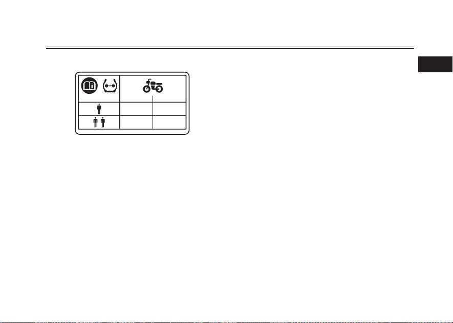
l weight of the operator, pas-
The tota
senger, accessories and cargo must
not exceed the maximum load limit.
Operation of an overloaded vehicle
could cause an accident.
Maximum load:
152 kg (335 lb)
2-3
When loading within this weight limit,
keep the following in mind:
z Cargo and accessory weight
should be kept as low and close to
the motorcycle as possible. Securely pack your heaviest items as
close to the center of the vehicle
as possible and make sure to distribute the weight as evenly as
possible on both sides of the motorcycle to minimize imbala
instability.
z Shifting weights can create a sud-
den imbalance. Make sure that
accessories and cargo are securely attached to the motorcycle
before riding. Check accessory
mounts and cargo restraints frequently.
t Properly adjust the suspension
for your load (suspension-adjustable models only), and
check the condition and pressure of your tires.
t Never attach any large or heavy
items to the handlebar, front
fork, or front fender. These
items, including such cargo as
nce or

sleeping bags, duffel bags, or
tents, can create unstable handling or a slow steering response.
z This vehicle is not designed to
pull a trailer or to be attached to
a sidecar.
Genuine Yamaha Accessories
Choosing accessories for your vehicle
is an important decision. Genuine
Yamaha accessories, which are available only from a Yamaha dealer, have
been designed, tested, and approved
by Yamaha for use on your vehicle.
Many companies with no connection
to Yamaha manufacture parts and accessories or offer other modications
for Yamaha vehicles.
a position to test the products that
these aftermarket companies produce.
Therefore, Yamaha can neither endorse nor recommend the use of accessories not sold by Yamaha or
modications not specically recommended by Yamaha, even if sold and
installed by a Yamaha dealer.
Yamaha is not in
Aftermarket Parts, Accessories, and
Modications
While you may nd aftermarket products similar in design and quality to
genuine Yamaha accessories, recognize that some aftermarket accessories or modications are not suitable
because of potential
you or others. Installing aftermarket
products or having other modications
performed to your vehicle that change
any of the vehicle’s design or operation
characteristics can put you and others
at greater risk of serious injury or
death. You are responsible for injuries
related to changes in the vehicle.
Keep the following guidelines in mind,
as well as those provided under “Loading” when mounting accessories.
z Never install accessories or carry
cargo that would impair the performance of y
Carefully inspect the accessory
before using it to make sure that it
does not in any way reduce
ground clearance or cornering
clearance, limit suspension travel,
safety hazards to
our motorcycle.
2-4
Safety information
steering travel or control operation, or obscure lights or reectors.
t Accessories tted to the han-
dlebar or the front fork area can
create instability due to improper weight distribution or aerodynamic changes. If accessories
are added to the handlebar or
front fork area, they must be as
lightweight as possible and
should be kept to a
t Bulky or large accessories may
seriously affect the stability of
the motorcycle due to aerodynamic effects. Wind may attempt to lift the motorcycle, or
the motorcycle may become
unstable in cross winds. These
accessories may also cause instability when passing or being
passed by large vehicles.
t Certain accessories can dis-
place the operator from his or
her normal riding position. This
improper position limits the
freedom of movement of the
minimum.
2

Safety information
operator and may limit control
ability, therefore, such accesso-
2
ries are not recommended.
z Use caution when adding electri-
cal accessories. If electrical accessories exceed the capacity of
the motorcycle’s electrical system, an electric failure could result, which could cause a
dangerous loss of lights or engine
power.
Aftermarket Tires and Rims
The tires and rims that came with your
motorcycle were designed to match
the performance capabilities and to
provide the best combination of handling, braking, and comfort. Other
tires, rims,
may not be appropriate. See page 7-18
for tire specications and for information on servicing and replacing your
tires.
Transporting the Motorcycle
Be sure to observe following instructions before transporting the motorcycle in another vehicle.
sizes, and combinations
z Remove all loose items from the
motorcycle.
z Check that the fuel cock (if
equipped) is in the off position and
that there are no fuel leaks.
z Shift the transmission into gear
(for models with a manual transmission).
z Secure the mot
downs or suitable straps that are
attached to solid parts of the motorcycle, such as the frame or upper front fork triple clamp (and not,
for example, to rubber-mounted
handlebars or turn signals, or
parts that could break). Choose
the location for the straps carefully
so the straps will not rub against
painted surfaces during transport.
z The suspension should be com-
pressed somewhat by the tiedowns, if possible, so that the motorcycle will not bounce excessively during
orcycle with tie-
transport.
2-5
Further safe-riding points
z Be sure to signal clearly when
making turns.
z Braking can be extremely difcult
on a wet road. Avoid hard braking,
because the motorcycle could
slide. Apply the brakes slowly
when stopping on a wet surface.
z Slow down as you approach a
corner or turn. Once you have
completed a turn, accelerate
slowly.
z Be careful when passing parked
cars. A driver might not see you
and open a door in your path.
z Railroad crossings, streetcar rails,
iron plates on road construction
sites, and
come extremely slippery when
wet. Slow down and cross them
with caution. Keep the motorcycle
upright, otherwise it could slide
out from under you.
z The brake pads or linings could
get wet when you wash the motorcycle. After washing the motorcycle, check the brakes before
riding.
manhole covers be-
EAU57610

z Always wear a helmet, gloves,
trousers (tapered around the cuff
and ankle so they do not ap), and
a brightly colored jacket.
z Do not carry too much luggage on
the motorcycle. An overloaded
motorcycle is unstable. Use a
strong cord to secure any luggage
to the carrier (if equipped). A loose
load will affect the stability of the
motorcycle and could divert your
attention from the road. (See page
2-3.)
Helmets
EAUN0532
Operating this vehicle without an approved motorcycle helmet increases
your chances of a
severe head injury or
death in the event of an accident. The
majority of fatalities from motorcycle or
scooter accidents are the result of
head injuries. The use of a safety helmet is the single most critical factor in
the prevention or reduction of head injuries.
Always select an approved motorcycle helmet
Pay attention to the following when
choosing a motorcycle helmet.
z The helmet must meet the safety
standard “SIRIM”.
z The helmet size must match the
size of the rider’s head.
z Never subject a helmet to heavy
hocks.
s
Wearing the helmet correctly
Always connect the chin strap. In the
case of an accident, the helmet has a
much less chance of coming off if the
chin strap is connected.
2-6
Safety information
Correct usage
2
ZAUU0003
Wrong usage
ZAUU0007
Types of helmets and their usage
z Half-type: use only for riding at low
speeds
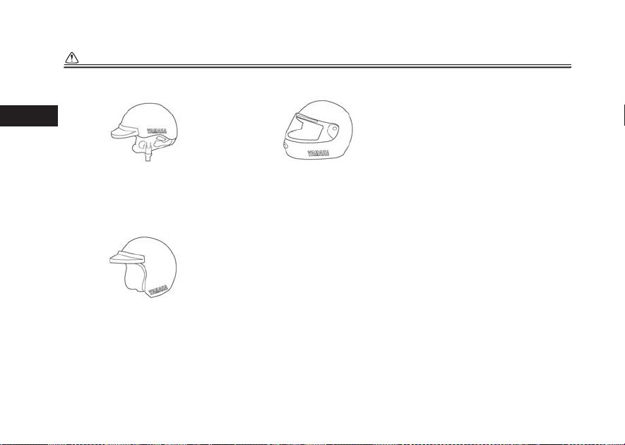
Safety information
2
ZAUU0004
z Full-type: use only for riding at low
to mid-range speeds
ZAUU0005
z Full-face-type: use for riding at
mid-range to high speeds
ZAUU0006
2-7

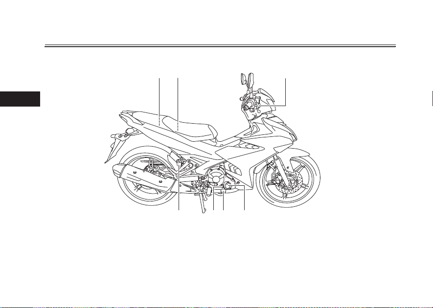
Left view
654321
7891011
Description
EAU10411
3
1. Front turn signal light (page 7-34)
2. Headlight (page 7-33)
3. Air lter element (page 7-15)
4. Battery (page 7-31)
5. Owner’s tool kit (page 7-1)
6. Rear turn signal light (page 7-35)
7. Sidestand (page 4-17)
8. Centerstand (page 7-29)
9. Engine oil drain bolt (page 7-11)
10.Shift pedal (page 4-12)
11.Coolant reservoir (page 7-14)
3-1
Description
Right view
3
EAU10421
321
1. Fuel tank cap (page 4-13)
2. Fuses (page 7-32)
3. Front brake uid reservoir (page 7-23)
4. Engine oil lter element (page 7-11)
5. Brake pedal (page 4-13)
6. Dipstick (page 7-11)
7. Rear brake uid reservoir (page 7-23)
4567
3-2
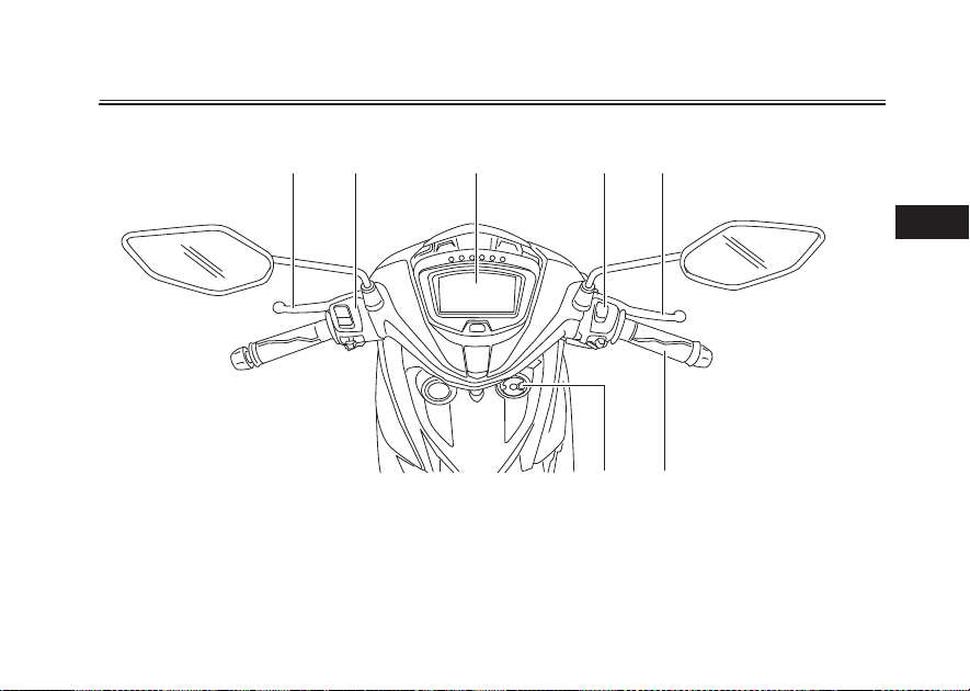
Controls and instruments
1
Description
EAU10431
2
3 4 5
3
1. Clutch lever (page 4-12)
2. Left handlebar switches (page 4-11)
3. Multi-function display (page 4-6)
4. Right handlebar switches (page 4-11)
5. Brake lever (page 4-12)
6. Throttle grip (page 7-17)
7. Main sw itch/steering lock (page 4-3)
76
3-3
Instrument and control functions
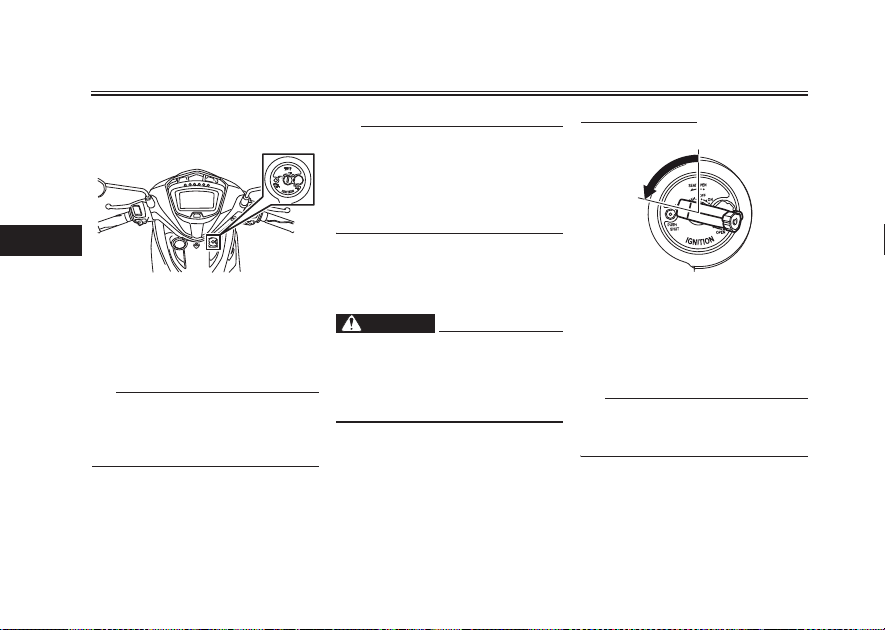
EAUU0352
Main switch/steering lock
4
The main switch/steering lock controls
the ignition and lighting systems, and is
used to lock the steering, and is used
to open the seat also. The various main
switch positions are described below.
TIP
The main switch is equipped with a
keyhole cover. (See page 4-4 for keyhole cover opening and closing procedures.)
ON
All electrical circuits are supplied with
power, and the engine can be started.
The key cannot be removed.
TIP
z The meter lighting, taillight, license
z The fuel pump can be heard when
OFF
All electrical systems are off. The key
can be removed.
Never turn the key to “OFF” while
the vehicle is moving, otherwise the
electrical systems will be switched
off, which may result in loss of control or an accident.
LOCK
The steering is locked, and all electrical
EAU65811
systems are off. The key can be removed.
plate light and auxiliary lights
come on automatically when the
key is turned to “ON”.
the key is turned to “ON”.
EAU45752
EWA10073
WARNING
EAUU1043
4-1
To lock the steering
OFF
LOCK
ZAUV0301
1. Turn the handlebars all the way to
the left.
2. Push the key in from the “OFF”
position, and then turn it to
“LOCK” while still pushing it.
3. Remove the key.
TIP
If the steering will not lock, try turning
the handlebars back to the right slightly.
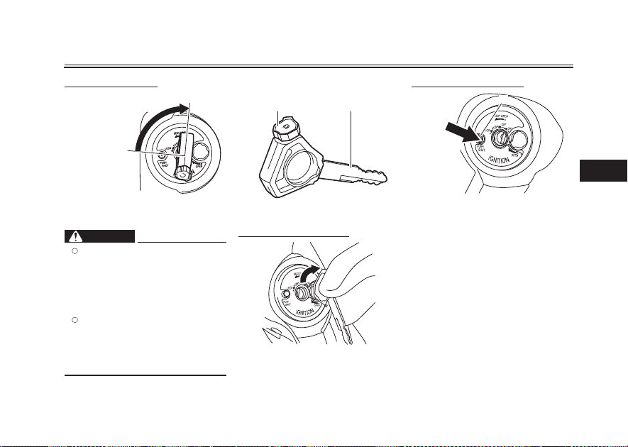
To unlock the steering
OFF
Keyhole cover
1 2
Instrument and control functions
EAUU0822
To close the keyhole cover
1
LOCK
ZAUV0302
Push the key in, and then turn it to
“OFF” while still pushing it.
WARNING
Never turn the key to “OFF” or
z
“LOCK” while the vehicle is
moving; otherwise, the electrical systems will be switched off,
which may result in loss of control or an accident.
If the vehicle turns over, and af-
z
ter placing it upright, ensure
that there is no fuel leakage. If
fuel is leaking, have a Yamaha
dealer check the vehicle.
EWAU0042
ZAUV0303
1. Key head
2. Ignition key
To open the keyhole cover
Insert the key head into the keyhole
cover receptacle as shown, and then
turn the key to the right to open the
cover.
4-2
4
1. “PUSH SHUT” button
Press the “PUSH SHUT” button to
close the keyhole cover.
Instrument and control functions
EAU4939G
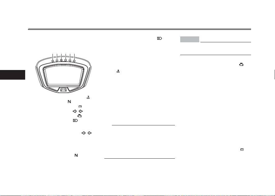
Indicator lights and warning
lights
1234 5 6
4
1. Coolant temperature warning light “ ”
2. Neutral indicator light “ ”
3. Battery voltage warning light “ ”
4. Turn signal indicator light “ ”
5. Engine trouble warning light “ ”
6. High beam indicator light “ ”
Turn signal indicator light “ ”
This indicator light ashes when a turn
signal light is ashing.
Neutral indicator light “ ”
This indicator light comes on when the
transmission is in the neutral position.
High beam indicator light “ ”
This indicator light comes on when the
high beam of the headlight is switched
on.
Coolant temperature warning
light “ ”
This warning light comes on when the
engine is overheating. If thi
stop the engine immediately and allow
the engine to cool.
When the vehicle is turned on, the light
will come on for a few seconds, and
then go off. If the light does not come
on, or if the light remains on, have a
Yamaha dealer check the vehicle.
TIP
EAU11022
z For vehicles with a radiator fan,
z If the engine overheats, see page
EAU11061
EAU11081
EAU11448
s occurs,
the radiator fan(s) automatically
switch on or off according to the
coolant temperature.
7-40 for further instructions.
4-3
NOTICE
ECA10022
Do not continue to operate the engine if it is overheating.
Engine trouble warning light “ ”
EAU11507
This warning light comes on or ashes
if a problem is detected in the electrical
circuit monitoring the engine. If this occurs, have a Yamaha dealer check the
self-diagnosis system.
The electrical circuit of the warning
light can be checked by turning the vehicle on. The warning light should
come on for a few seconds, and then
go off.
If the warning light does not come on
initially when the vehicle is turned on,
or if the warning light remains o
n, have
a Yamaha dealer check the electrical
circuit.
Battery voltage warning light “ ”
EAUU2111
This warning light comes on when the
battery voltage gets low.
If this occurs, have a Yamaha dealer
check the battery for charging.
TIP
1
When the vehicle is turned on, the light
will come on for a few seconds, and
then go off. If the light does not come
on, or if the light remains on, have a
Yamaha dealer check the vehicle.
Instrument and control functions
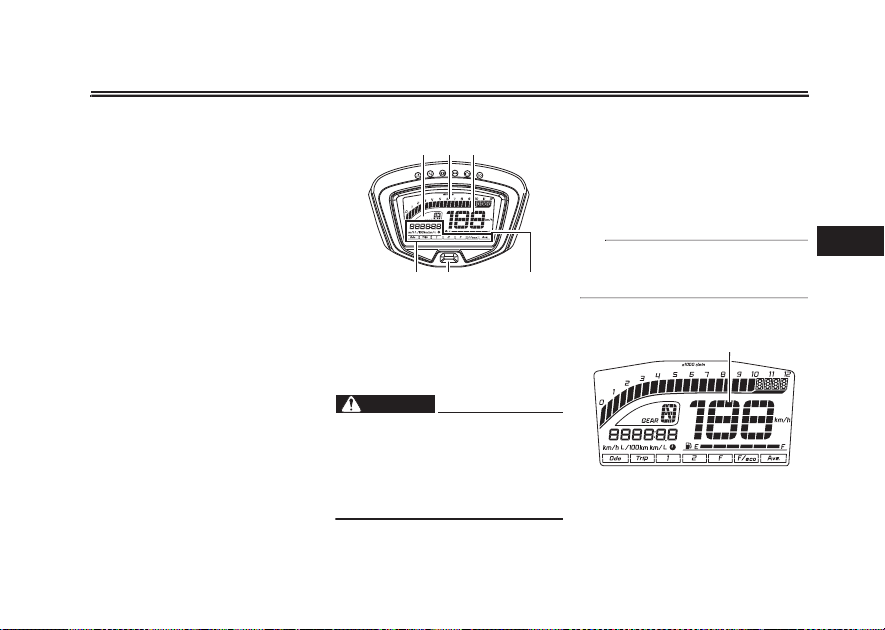
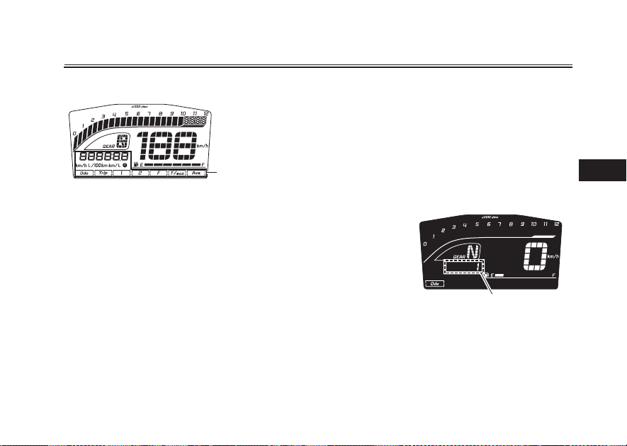
Multi-function meter unit
1
23
1. Transmission gear display
2. Tachometer
3. Speedometer
4. Fuel meter
5. “RESET/SELECT” button
6. Multi-function display
Be sure to stop the vehicle before
making any setting changes to the
multi-function meter unit. Changing
settings while riding can distract the
operator and increase the risk of an
accident.
65 4
WARNING
4-4
EAU84712
EWA12423
The multi-function meter unit is
equipped with the following:
z a speedometer
z a tachometer
z a transmission gear display
z a fuel meter
z a multi-function display
Be sure to turn the main switch on before using the “RESET/SELECT” button.
Speedometer
1. Speedometer
The speedometer shows the vehicle’s
traveling speed.
4
Instrument and control functions
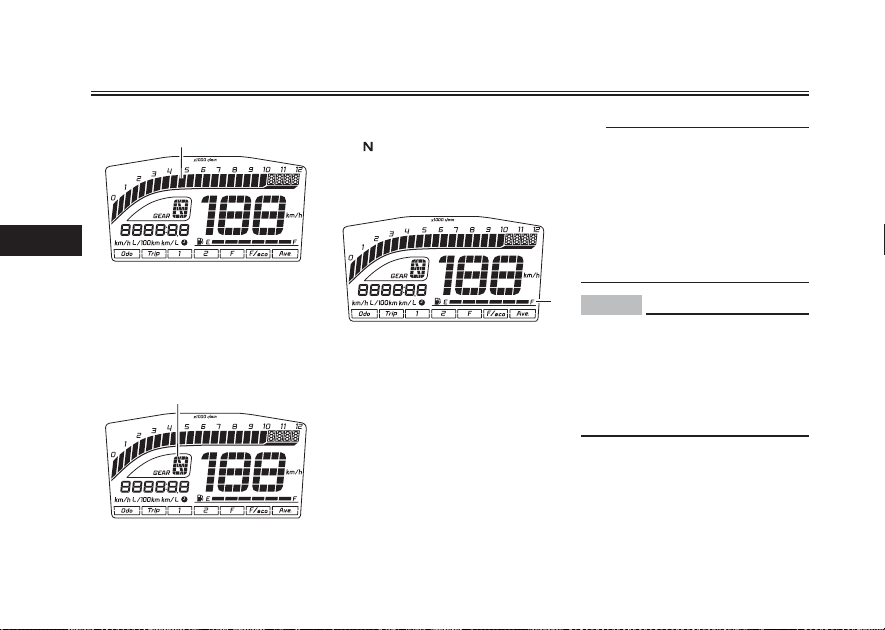
Tachometer
1
4
1. Tachometer
The electric tachometer allows the rider to monitor the engine speed and
keep it within the ideal power range.
Transmission gear display
1
1. Transmission gear display
The display shows the selected gear.
The neutral position is indicated
by “ ” and by the neutral indicator
light.
Fuel meter
1. F uel meter
The fuel meter indicates the amount of
fuel in the fuel tank. The display segments of the fuel meter disappear from
“F” (full) towards “E” (empty) as the fuel
level decreases. When the last segment start ashing, refuel as soon as
possible.
When the main switch is turned on, all
of the display segments of the fuel meter will appear for a few seconds, and
then the fuel meter shows the actual
fuel level.
4-5
TIP
z Do not use up all of the fuel in the
fuel tank.
z The fuel meter is equipped with a
self-diagnosis function. If a problem is detected in the fuel meter
electrical circuit, all the display
segments will ash repeatedly. If
this occurs, have a Yamaha dealer
check the vehicle.
1
NOTICE
When the fuel indicator has dropped
to only one block, refuel as soon as
possible, as the movement of fuel
when going up or downhill or when
turning may lead to the engine not
getting any fuel, resulting in engine
stop.
ECAV0041
Instrument and control functions
Multi-function display age fuel consumption mode “AVE_ _._
1. Multi-function display
The multi-function display is equipped
with the following:
z an odometer
z two tripmeters
z a fuel reserve tripmeter
z a clock
z an instantaneous fuel consump-
tion display
z an average fuel consumption dis-
play
z an average speed display
Push the “RESET/SELECT” button to
switch the display between the odometer mode “ODO”, tripmeters mode
“TRIP 1” and “TRIP 2”, clock mode “ _
_:_ _ ”, instantaneous fuel consumption mode “km/L” or “L/100 km”, aver-
km/L” or “AVE_ _._ L/100 km” and average speed mode “AVE_ _._ km/h” in
the following order:
ODO o TRIP 1 o TRIP 2 o CLOCK o
km/L or L/100 km o AVE_ _._ km/L or
AVE_ _._ L/100 km o AVE_ _._ km/h o
1
ODO
If the last segment of the fuel meter
starts ashing, the display automatically changes to the fuel reserve tripmeter mode “TRIP F” and starts
counting the distance traveled from
that point. In that case, push the “RESET/SELECT” button to swi
play between the various tripmeter,
odometer, clock, instantaneous fuel
consumption, average fuel consumption, and average speed modes in the
following order:
TRIP F o CLOCK o km/L or L/100 km
o AVE_ _._ km/L or AVE_ _._ L/100 km
o AVE_ _._ km/h o ODO o TRIP 1 o
TRIP 2 o TRIP F
4-6
tch the dis-
To reset a tripmeter, select it by pushing the “RESET/SELECT” button for
one second.
If you do not reset the fuel reserve tripmeter manually, it resets itself automatically and the display returns to the
prior mode after ref
5 km.
Odometer mode
ueling and traveling
1
1. Odometer
The odometer shows the total distance
traveled by the vehicle. It cannot be reset.
4

Instrument and control functions
Tripmeters mode
4
1
1. Tripmeter
The tripmeters shows the total distance traveled since they were last reset.
To reset a tripmeter, push the “RESET/SELECT” button for one second.
TIP
z The odometer will lock at 999999
and cannot be reset.
z The tripmeters will reset and con-
tinue counting after 9999.9 is
reached. To reset the tripmeters,
while it is being displayed, press
the “RESET/SELECT” button for
at least one second.
Clock mode
1. Clock
The clock uses a 12-hour time system.
To set the clock
1. With the display in the clock
2. When the hour digits start ash-
3. Push the “RESET/SELECT” but-
4. Use the “RESET/SELECT” button
5. Push the “RESET/SELECT” but-
1
mode, push the “RESET/SELECT”
button for two seconds.
ing, use the “RESET/SELECT”
button to set the hours.
ton for two seconds, and the minutes will start ashing.
to set the minutes.
ton for two seconds to start the
clock.
4-7
TIP
If you do not push the “RESET/SELECT” button for 90 seconds, the
clock will not be set and will return to
the prior time.
Instantaneous fuel consumption
mode
1
1. Instantaneous fuel consumption display
Shows the current fuel consumption
when the vehicle is traveling at least 10
km/h.
There are two display modes: “km/L”
and “L/100 km”.
To switch the instantaneous fuel consumption display between “km/L” and
“L/100 km”, push the “RESET/SELECT” button for one second.

z “km/L”: The distance that can be
1
traveled on 1.0 L of fuel under the
current riding conditions is shown.
z “L/100 km”: The amount of fuel
necessary to travel 100 km under
the current riding conditions is
shown.
TIP
z If traveling at speeds under 10
km/h, “_ _._” is displayed.
z The instantaneous fuel consump-
tion function should be used for
general reference only. Do not use
this gure to estimate the distance
that can be traveled on the current
tank of fuel.
Instrument and control functions
Average fuel consumption mode
1. Average fuel consumption display
Show the average fuel consumption
since it was last reset.
There are two display mode: “AVE_ _._
km/L” and “AVE_ _._ L/100 km”.
The average fuel consumption display
mode is set to the same as the instantaneous fuel consumption display
mode.
z “AVE_ _._ km/L”: The average dis-
tance that can be traveled on 1.0 L
of fuel is shown.
z “AVE_ _._ L/100 km”: The average
amount of fuel necessary to travel
100 km is shown.
To reset the average fuel consumption
display, press the “RESET/SELECT”
one second.
button for
1
4-8
TIP
After resetting the average fuel consumption, “_ _._” will be shown until
the vehicle has traveled 1 km.
The average fuel consumption function
should be used for general reference
only. Do not use this gure to estimate
the distance that can be traveled on
the current tank of fuel.
Average speed mode
1. Average speed display
Shows the vehicle’s traveling speed
since it was last reset.
To reset the average speed display,
press the “RESET/SELECT” button for
one second.
4
Instrument and control functions
P
ASS
12 3
EAU1234M
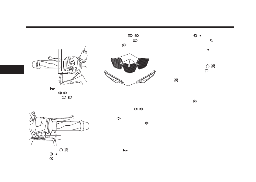
Handlebar switches
Left
4
1. Horn switch “ ”
2. Turn signal switch “ / ”
3. Dimmer/Pass switch “ / /PASS”
Right
1
OFF
1. Engine stop switch “ / ”
2. Light switch “ / ”
3. Start sw itch “ ”
2
3
Dimmer switch “ / ”
Set this switch to “ ” for the high
beam and to “ ” for the low beam.
1. Headlight (low beam)
2. Headlight (high beam)
3. Auxiliary light
Turn signal switch “ / ”
To signal a right-hand turn, push this
switch to “ ”. To signal a left-hand
turn, push this switch to “ ”. When
released, the switch returns to the center position. To cancel the turn signal
lights, push the switch in after it has returned to the center position.
Horn switch “ ”
Press this switch to sound the hor
3
4-9
EAU12402
Light switch “ / ”
EAU12582
Set the light switch to “ ” to turn on
the headlight, taillight and meter light-
1
2
ing. Set the switch to “ ” to turn off all
the lights.
Engine stop switch “ / ”
EAU12663
Set this switch to “ ” (run) before
starting the engine. Set this switch
to “ ” (stop) to stop the engine in case
of an emergency, such as in the event
of an overturn or if the throttle is stuck.
Start switch “ ”
EAU12461
Push this switch to crank the engine
e starter. See page 6-2 for start-
with th
EAU12713
ing instructions prior to starting the engine.
EAU12501
n.

Clutch lever
EAU31642
1
P
A
S
S
1. Clutch lever
The clutch lever is located on the left
side of the handlebar. To disengage
the clutch, pull the lever toward the
handlebar grip. To engage the clutch,
release the lever. The lever should be
pulled rapidly and released slowly for
smooth clutch operation.
The clutch lever is equipped with a
clutch switch, which is part of the starting circuit cut-off system. (See page
4-18.)
Instrument and control functions
Shift pedal
5
4
3
2
N
1
1
1. Shift pedal
The shift pedal is located on the left
side of the motorcycle. To shift the
transmissio
the shift pedal up. To shift to the transmission to a lower gear, move the shift
pedal down. (See page 6-2.)
n to a higher gear, move
4-10
EAU12875
Brake lever
EAU12892
1
1. Brake lever
The brake lever is located on the right
side of the handlebar. To apply the
front brake, pull the lever toward the
throttle grip.
4
 Loading...