

Yamaha XZ550RJ SERVICE MANUAL

YAMAHA
XZ550RJ
SERVICE MANUAL
11H-28197-10
1
FEATURES
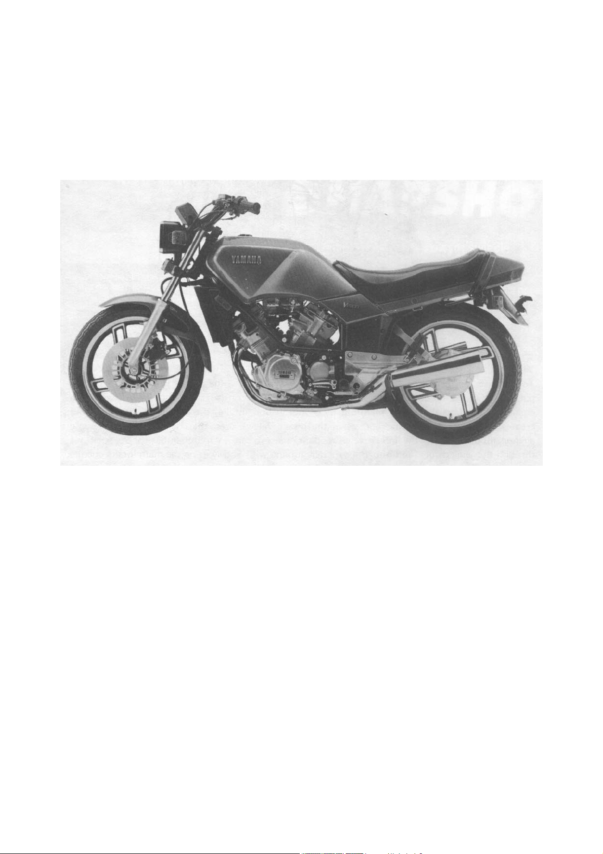
XZ550RJ
Liquid-cooled V-Twin
The 70° V-Twin engine is liquid-cooled to maintain the best operating temperature range. The cooling system
features an aluminum-corrugate radiator which is extremely light and exhibits excellent heat-dissipating characteristics. An automatically activated electric fan pulls air through the radiator in heavy-traffic situations. The
system has an automotive-type expansion and recovery tank which makes airspace in the radiator unnecessary and virtually eliminates coolant loss on even the hottest days. A thermostatic valve mounted in the engine
block provides quick warmups and stable coolant temperature.
2
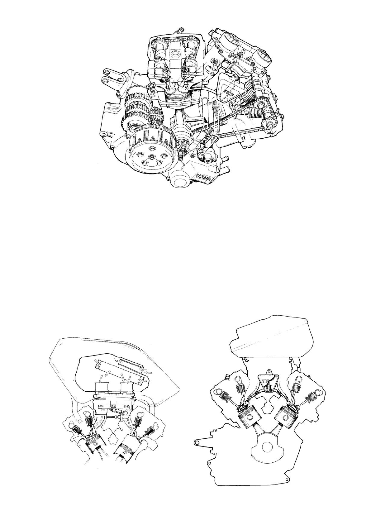
YICS
To increase fuel economy through more efficient combustion, the engine is equipped with the patented Yamaha Induction Control System (YICS). In this configuration, the YICS consists of a chamber linked to the intake manifold by a tube. Upon intake, the vacuum in the manifold creates a vacuum in the chamber; when the
intake valve closes, the chamber draws in some air-fuel mixture. When the intake valve reopens, the mixture
in the chamber shoots back out through the angled tube and into the cylinder, mixing with and swirling the
main intake charge. The swirling charge is then compressed and ignited, burning more completely and producing more power than that of a conventional engine.
INTAKE SYSTEM AND YICS
3

LIQUID COOLING SYSTEM
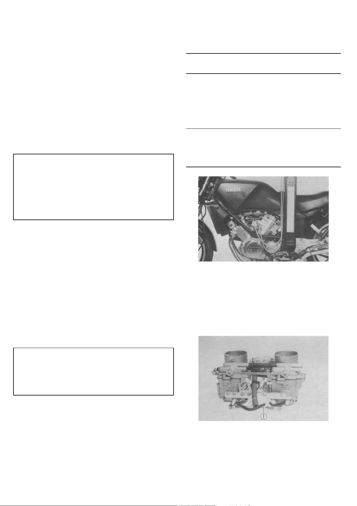
Downdraft carb
The induction system on this motorcycle features downdraft carburetion. The 34 mm (1.34 in) Venturis are
positioned so that the incoming air takes a virtually straight path through the carbs and the intake manifolds to
the combustion chambers; intake efficiency is remarkably high. An accelerator pump is installed in the carburetor assembly to eliminate hesitation when the throttle is opened at low engine speeds. A fuel pump delivers
gas from the tank to the float bowls, and a regulator sends excess fuel through a circuit back to the fuel pump
inlet.
DOHC 4-valve heads
Each cylinder head has dual overhead camshafts, and each camshaft acts directly on top of the valves; there
are no pushrods or rocker arms. Both heads have four valves, two intake and two exhaust, instead of one intake and one exhaust valve. By using two slightly smaller valves in place of each large valve, port area is significantly increased. This provides a much greater volume of mixture and exhaust flow. In addition, the smaller,
lighter valves are easier to control at high engine speeds; the valves can follow the cam profiles more closely
to resist "floating" and allow a 9,500 r/min red line.
4
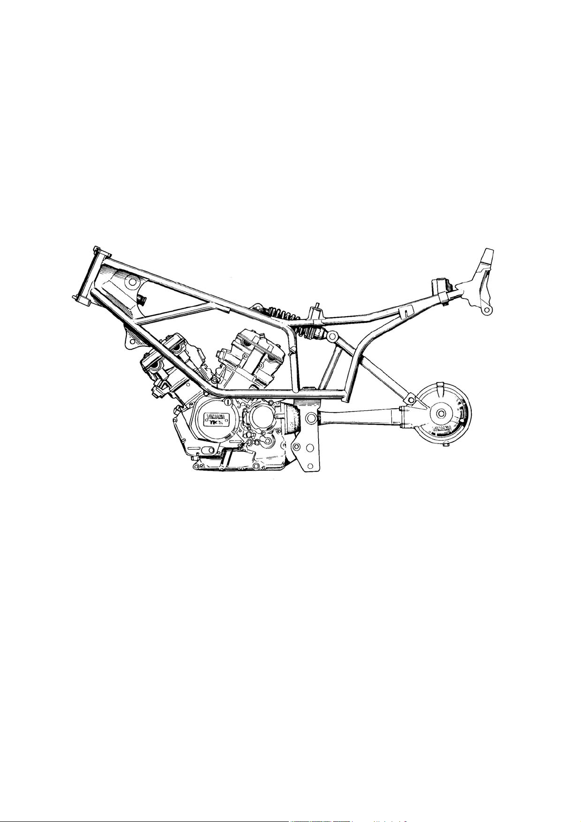
Chassis bits
The "hang-support" frame on this motorcycle allows a lower engine placement and center of gravity while providing excellent rigidity for precise handling. Cornering clearance is also enhanced. The trailing-axle front suspension performs superbly. The axle placement helps to maintain a short wheelbase, allowing quick, sporty
handling. Yamaha's proven Monoshock rear suspension provides the excellent handling and comfort characteristics for which it is famous. The spring preload is adjustable to five settings.
FRAME AND MONOCROSS SUSPENSION SYSTEM
5

NOTICE
This manual was written by the Yamaha Motor Company primarily for use by Yamaha dealers and their qualified mechanics. It is not possible to put an entire mechanic's education into one manual, so it is assumed that
persons using this book to perform maintenance and repairs on Yamaha motorcycles have a hasic understanding of the mechanical concepts and procedures inherent to motorcycle repair technology. Without such
knowledge, attempted repairs or service to this model may render it unfit to use and/or unsafe.
This model has been designed and manufactured to perform within certain specifications in regard to performance and emissions. Proper service with the correct tools is necessary to ensure that the motorcycle will operate as designed. If there is any question about a service procedure, it is imperative that you contact a Yamaha
dealer for any service information changes that apply to this model. This policy is intended to provide the customer with the most satisfaction from his motorcycle and to conform with federal environmental quality objectives.
Yamaha Motor Company, Ltd. is continually striving to improve all models manufactured by Yamaha. Modifications and significant changes in specifications or procedures will be forwarded to all Authorized Yamaha dealers and will, where applicable, appear in future editions of this manual.
NOTE:
This Service Manual contains information regarding periodic maintenance to the emission control system for
the XZ550RJ. Please read this material carefully.
Particularly important information is distinguished in this manual by the following notations:
NOTE: A NOTE provides key information to make procedures easier or clearer.
CAUTION: A CAUTION indicates special procedures that must be followed to avoid damage to the motorcy-
cle.
WARNING: A WARNING indicates special procedures that must be followed to avoid injury to a motorcycle
operator or person inspecting or repairing the motorcycle.
SERVICE DEPT.
INTERNATIONAL DIVISION
YAMAHA MOTOR CO., LTD.
6

CHAPTER 1. GENERAL INFORMATION
MOTORCYCLE IDENTIFICATION………………………………………………………………………………..... 8
Frame serial number……………………………………………………………………………………….. 8
Engine serial number………………………………………………………………………………………. 8
Vehicle identification number…………………………………………………………………………….. 8
SPECIAL TOOLS……………………………………………………………………………………………………... 9
For tune-up…………………………………………………………………………………………………… 9
For engine service………………………………………………………………………………………….. 9
For chassis service…………………………………………………………………………………………. 12
For middle gear service……………………………………………………………………………………. 12
For shaft drive service……………………………………………………………………………………... 13
For electrical components………………………………………………………………………………… 13
7
GENERAL INFORMATION
MOTORCYCLE IDENTIFICATION
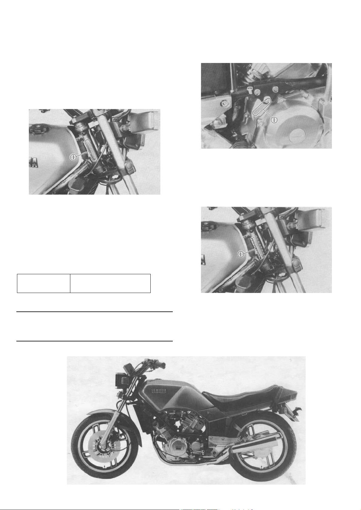
Frame serial number
The frame serial number is stamped into the right
side of the steering head pipe.
1. Frame serial number
Engine serial number The engine serial number is stamped into the elevated part of the right rear section of the engine.
Starting serial number:
XZ550RJ
11H-000101
NOTE
The first three digits of these numbers are for model
identification; the remaining digits are the unit production number.
1. Engine serial number
Vehicle identification number The vehicle identification number is on the left side of the steering head pipe.
1. Vehicle identification number
8
SPECIAL TOOLS The proper special tools are necessary for complete and accurate tune-up and assembly. Using the correct special tool will help prevent damage caused by the use of improper tools or improvised techniques.
For tune-up Inductive tachometer (P/N YU-08036)
Inductive timing light (P/N YU-08037)
Fuel level gauge (P/N YM-01312)
Cooling system tester (P/N YU-24460)
Compression gauge (P/N YU-33223)
Compression gauge
12 mm (0.47 in) adapter (P/N YU-33223-3)
Vacuum gauge (P/N YU-08030)
Tappet adjusting tool (P/N YM-28899)
This tool is necessary to replace valve adjusting
pads.
Valve spring compressor
(P/N YM-04019)
This gauge is needed for carburetor synchronization
For engine service
Universal clutch holder
(P/N YM-91042)
This tool is used to hold the clutch when removing
or installing the clutch boss locknut
This tool must be used for removing and installing
the valve assemblies
Vavle guide remover
(P/N YM-04064)
This must be used to remove the valve guides
9
Valve guide reamer
(P/N YM-04066)
Flywheel puller
(P/N YU-33270)
This must be used when replacing the valve guide.
Valve guide installer
(P/N YM-04065)
This tool is needed for proper installation of the
valve guides.
Valve seat cutter set
(P/N YM-91043)
This tool is used for removing the flywheel
8mm (0,3 in) wrench adapter
(P/N YM-28897)
This tool is used to loosen or tighten the cylinder
head securing nut.
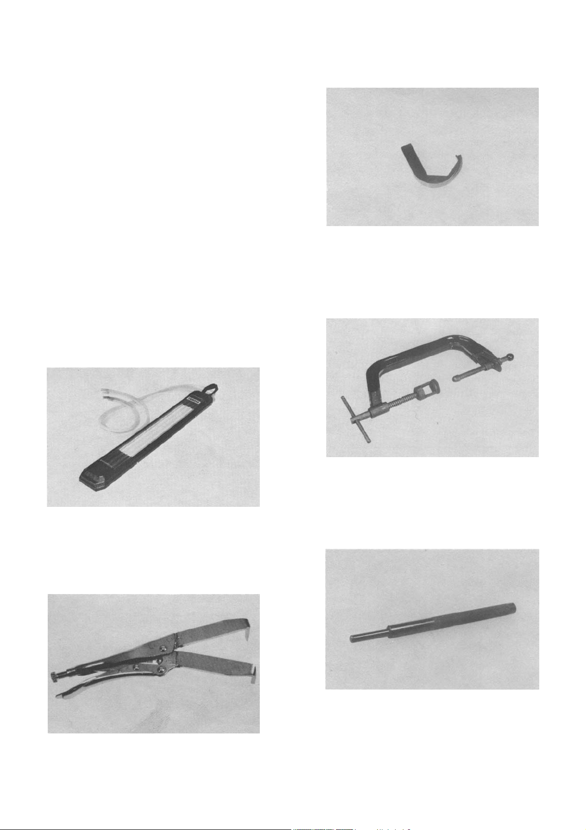
Water pump seal installer
(P/N YM-33221)
This tool is needed to resurface the valve seat.
This tool is needed for proper installation of the water pump seal.
10
Piston pin puller
(P/N YU-01304)
46 mm (1.8 in) offset wrench
(P/N YM-04045A)
This tool is used to remove the piston pin.
#30 Torx driver
(P/N YU-29843-6)
This tool is used to loosen or tighten the drive axle
bearing stopper bolt
#25 Torx driver
(P/N YU-29843-4)
This tool is used to loosen and tighten the primary
drive gear/balancer drive gear securing nut.
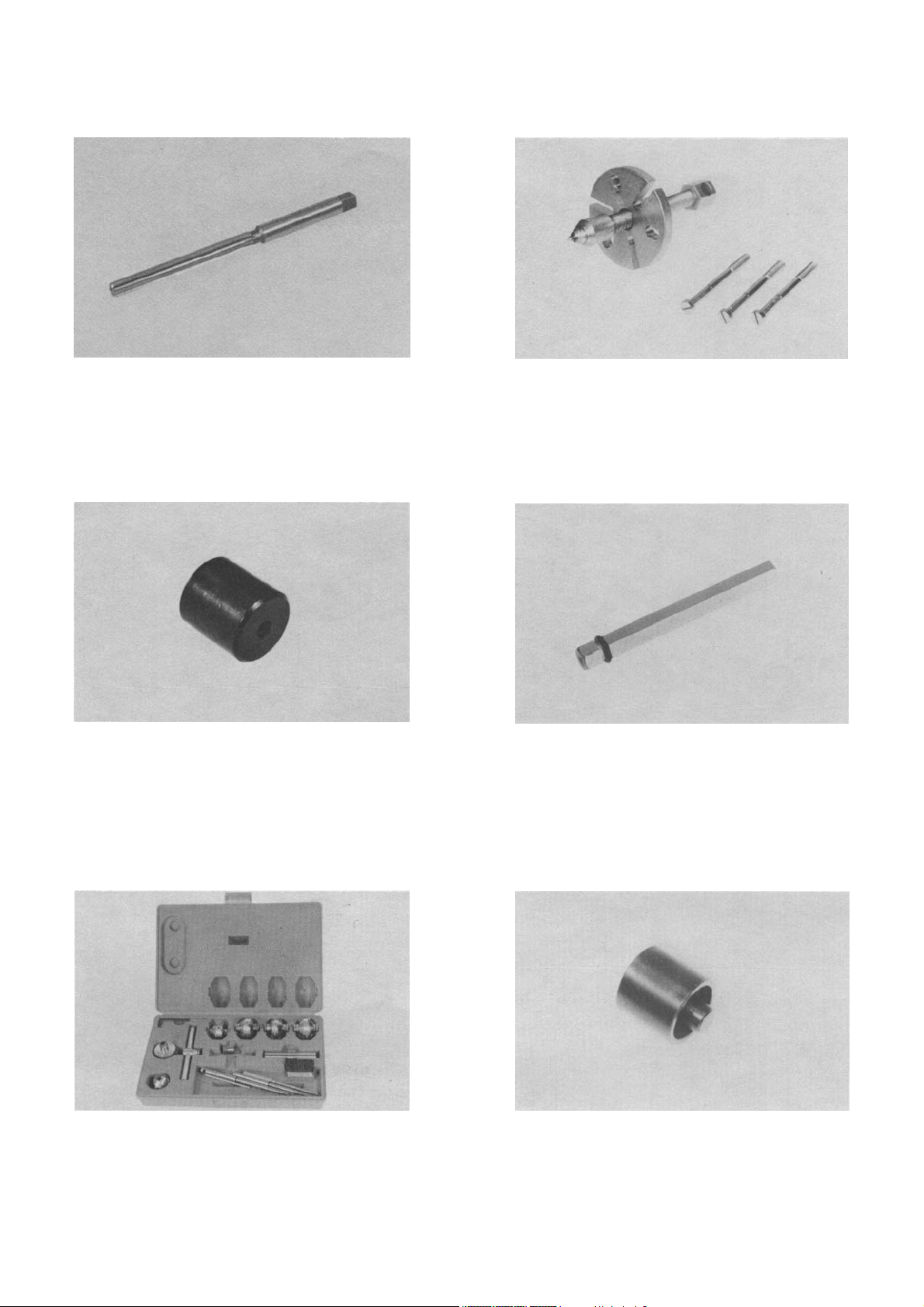
Plain bearing driver/installer
(P/N YM-28898)
Handle (P/N YM-04058-1)
This tool is used to loosen or tighten the shift cam
segment securing bolt
These tools are used for removing and installing the
crankshaft plain bearing.
11

Plastigauge set “Green”
(P/N YU-33210)
This gauge is needed when measuring clearance
for connecting rod bearing.
For chassis service
T-handle (P/N YU-01268) and damper rod holder
(P/N YM-33256)
For middle gear service
Universal joint holder
(P/N YM-04062)
This tool is used when adjusting gear lash, in the
middle gear.
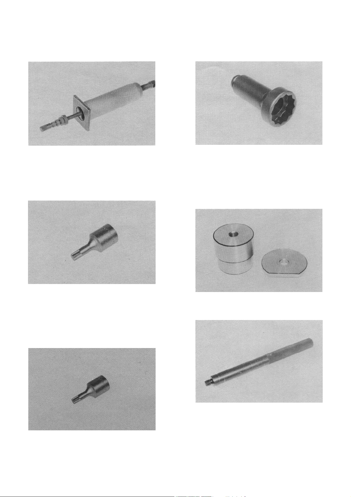
Middle drive gear holder
(P/N YM-33222)
This tool is used to loosen and tighten the fron fork
cylinder holding bolt
Front fork cap socket (19mm) (0.75 in))
(P/N YM-01298)
This tool is needed when loosening and tightening
the front fork cap bolt
This tool is needed when measuring gear back lash.
Dial indicator
(P/N YU-03097)
These tools are used when measuring gear lash for
middle gear.
12
For shaft drive service
Damper spring compressor
(P/N YM-04011)
This tool is needed to disassemble and reassemble
the middle gear damper.
Final drive gear lash tool
(P/N YM-01230)
Bearing retainer wrench
(P/N YM-33214)
This tool is used to loosen or tighten the bearing
retainer.
For electrical components
The uses of these tools are described in Chapter 6.
Electro tester
(P/N YU-03021)
This tool is needed when measuring gear lash for
final gear.
Ring gear holder
(P/N YM-01254)
This tool is needed when measuring gear lash.
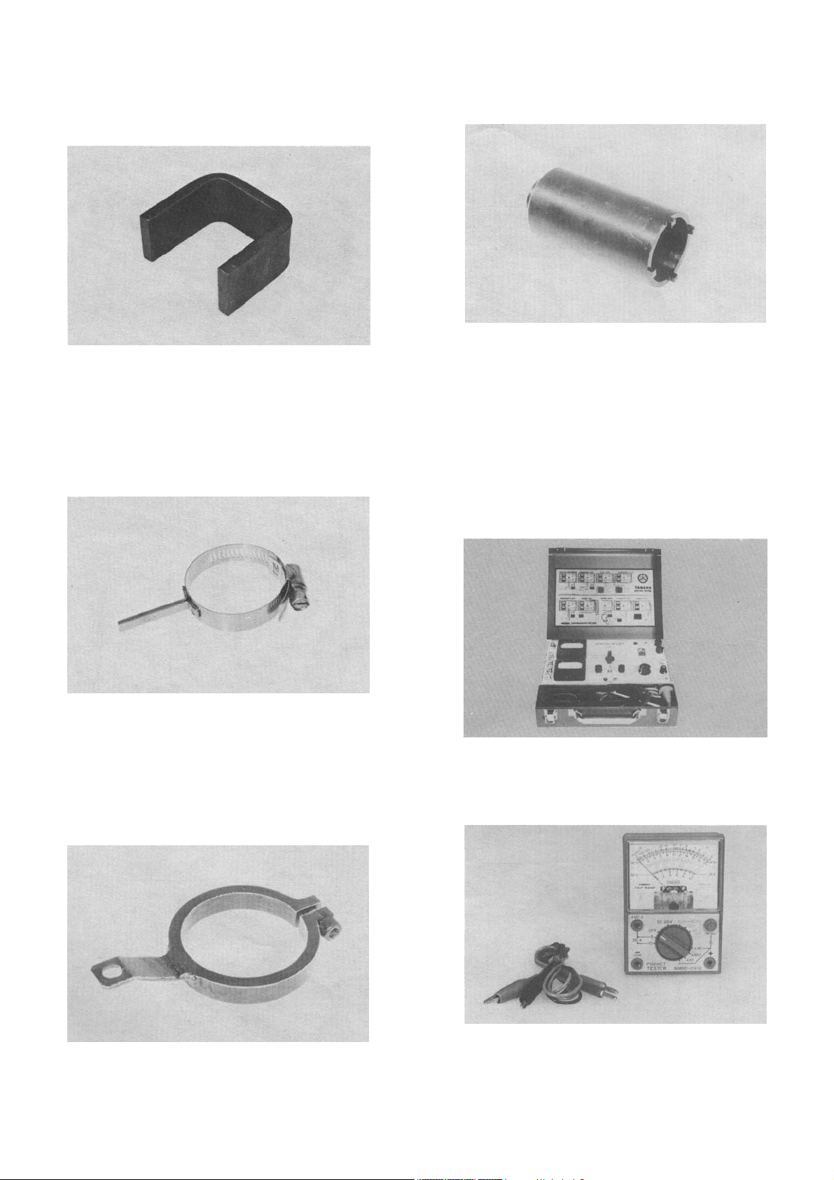
Pocket tester
(P/N YU-03112)
13

CHAPTER 2.
PERIODIC INSPECTIONS AND ADJUSTMENTS
INTRODUCTION…………………………………………………………………………………………………….. 15
MAINTENANCE INTERVALS CHARTS…………………………………………………………………………. 15
PERIODIC MAINTENANCE EMISSION CONTROL SYSTEM………………………………………………… 15
GENERAL MAINTENANCE/LUBRICATION……………………………………………………………………. 16
ENGINE………………………………………………………………………………………………………………. 17
Valve clearance adjustment………………………………………………………………………………… 17
Spark plug……………………………………………………………………………………………………… 23
Crankcase ventilation system……………………………………………………………………………… 23
Fuel line………………………………………………………………………………………………………… 23
Exhaust system………………………………………………………………………………………………. 23
Carburetor synchronization………………………………………………………………………………… 23
Idle speed……………………………………………………………………………………………………… 24
Engine oil………………………………………………………………………………………………………. 24
Coolant…………………………………………………………………………………………………………. 25
Clutch adjustment……………………………………………………………………………………………. 26
Checking ignition timing……………………………………………………………………………………. 27
Compression pressure measurement……………………………………………………………………. 27
CHASSIS…………………………………………………………………………………………………………….. 28
Final gear oil…………………………………………………………………………………………………… 28
Air filter…………………………………………………………………………………………………………. 28
Front and rear brake…………………………………………………………………………………………. 29
Brake light switch adjustment……………………………………………………………………………… 30
Front brake pad……………………………………………………………………………………………….. 30
Rear brake shoe………………………………………………………………………………………………. 31
Brake fluid……………………………………………………………………………………………………… 31
Cable inspection and lubrication………………………………………………………………………….. 31
Brake and change pedals/brake and clutch levers…………………………………………………….. 31
Centerstand and sidestand.................................………………………………………………………… 31
Front fork oil change………………………………………………………………………………………… 32
Rear shock absorber adjustment…………………………………………………………………………. 33
Steering head adjustment………………………………………………………………………………….. 33
Wheel bearings………………………………………………………………………………………………. 33
Front wheel……………………………………………………………………………………………………. 34
Rear wheel…………………………………………………………………………………………………….. 34
Fuel cock………………………………………………………………………………………………………. 34
Tubeless tires and aluminum wheels…………………………………………………………………….. 35
ELECTRICAL……………………………………………………………………………………………………….. 35
Battery………………………………………………………………………………………………………….. 35
Headlight……………………………………………………………………………………………………….. 36
Fuse……………………………………………………………………………………………………………... 37
14
INTRODUCTION
This chapter includes all information necessary to
perform recommended inspections and adjustments. These preventive maintenance procedures,
if followed, will ensure more reliable vehicle operation and a longer service life. The need for costly
overhaul work will be greatly reduced. This information applies to vehicles already in service and to
new vehicles that are being prepared for sale. All
service technicians should be familiar with this entire chapter.
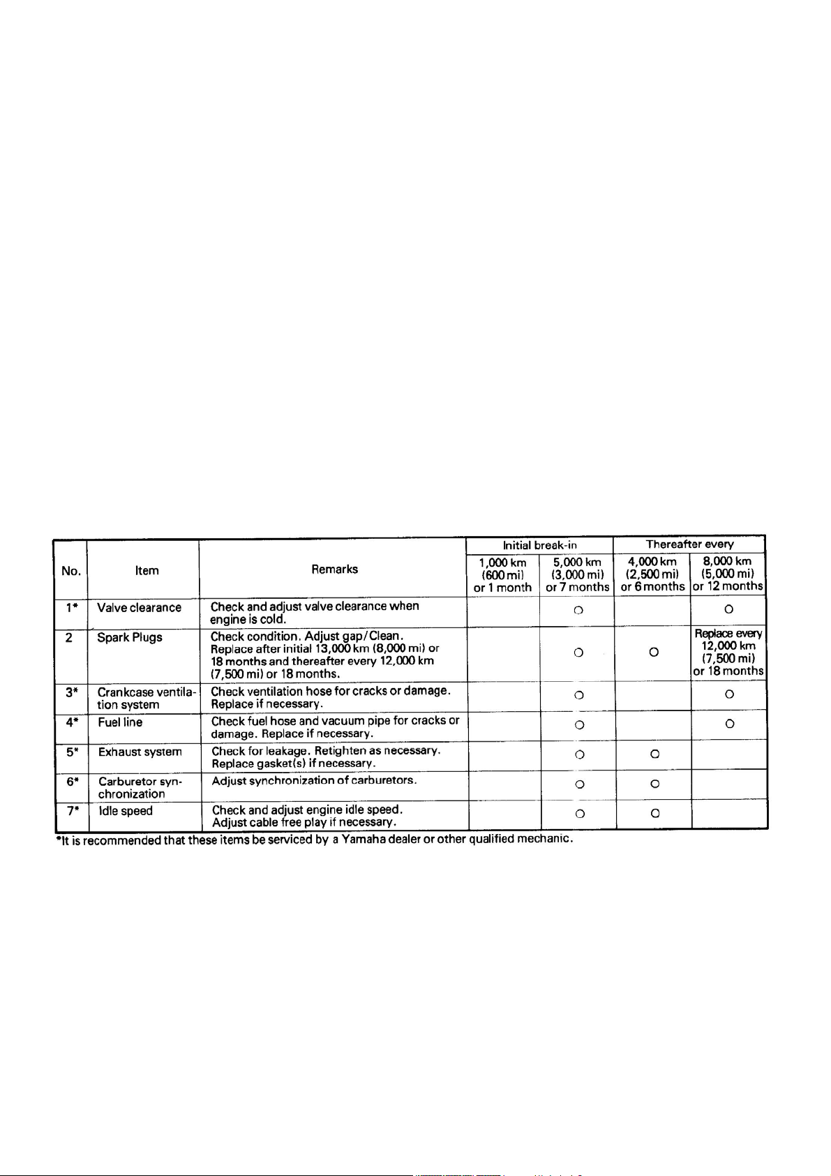
PERIODIC INSPECTIONS AND ADJUSTMENTS
PERIODIC MAINTENANCE EMISSION CONTROL SYSTEM
MAINTENANCE INTERVALS CHARTS
Proper periodic maintenance is important. Especially important are the maintenance services related to emissions control. These controls not only
function to ensure cleaner air but are also vital to
proper engine operation and maximum performance. In the following maintenance tables, the services related to emissions control are grouped separately.
15
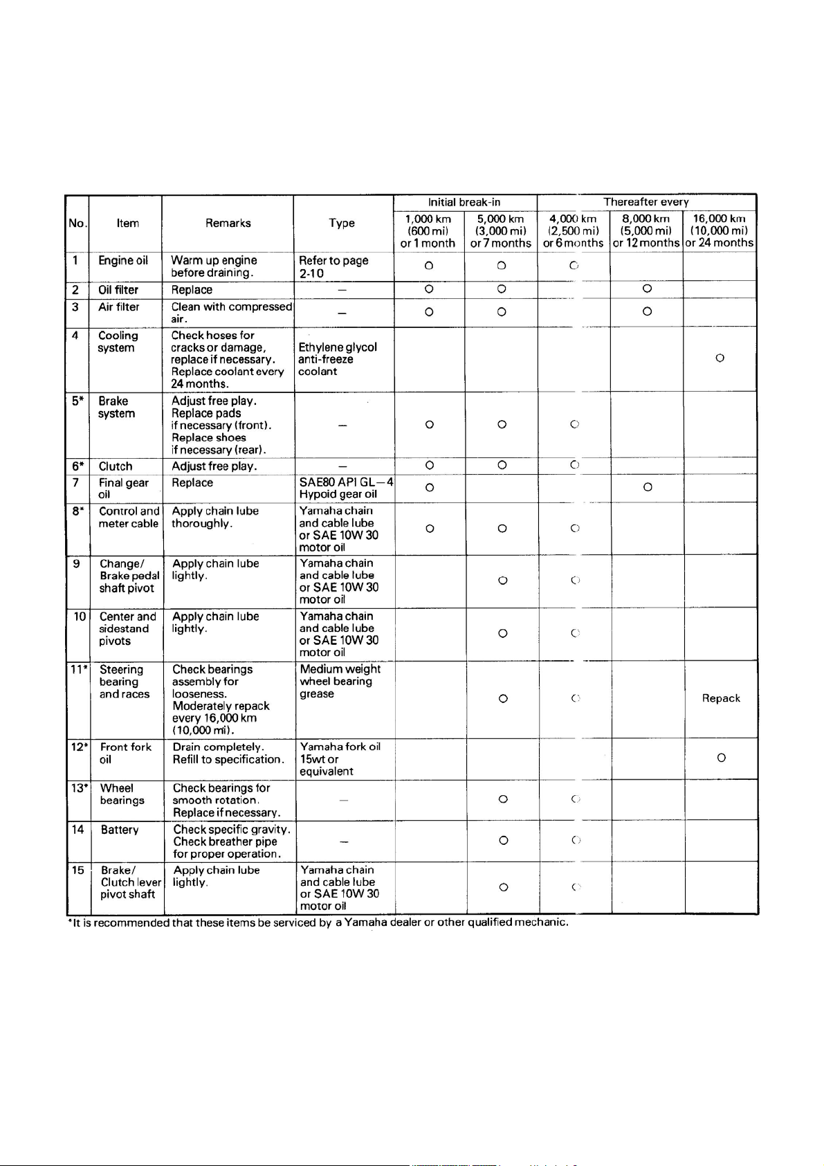
GENERAL MAINTENANCE/LUBRICATION
16
ENGINE
Valve clearance adjustment
Adjust the valve clearance as follows:
NOTE:
Valve clearance must be measured when the engine is cool to the touch.
1. Remove the seat, and remove the side covers, fuel tank, air filter assembly, and crankcase ventilation pipes.
1. Air baffle plate
1. Fuel tank holding bolt
CAUTION:
After removing the air filter assembly, cover the
carburetors with a clean rag to prevent dust or
any foreign materials from entering.
2. Remove the radiator cover and the radiator
securing bolts. Gently and firmly push the
left side of the radiator assembly towards the
front wheel. The right side of the radiator and
connected pipes should remain in place.
NOTE:
It is not necessary to completely remove the radiator
from the motorcycle.
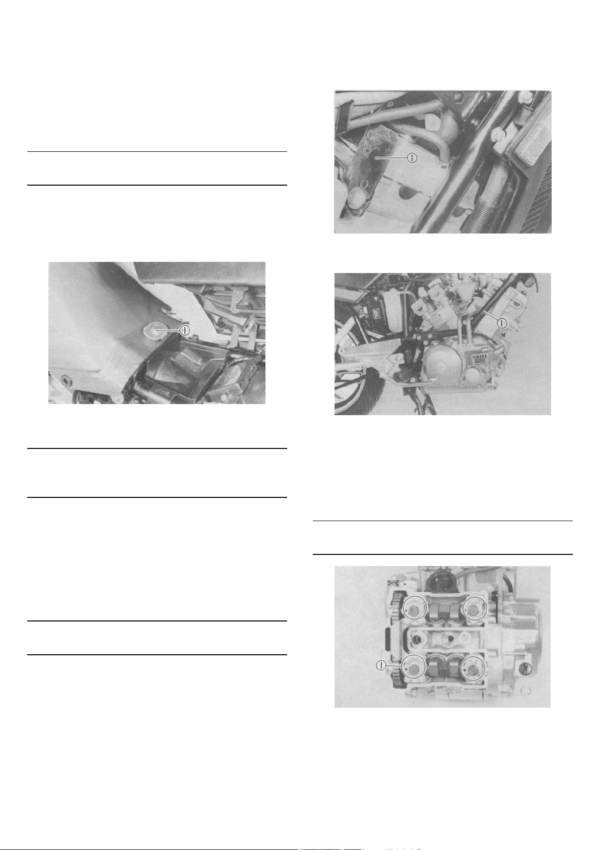
3. Remove the air baffle plate from behind the
front cylinder and remove the right side
frame tube.
1. Down tube frame
4. Disconnect the spark plug cap from each
cylinder head.
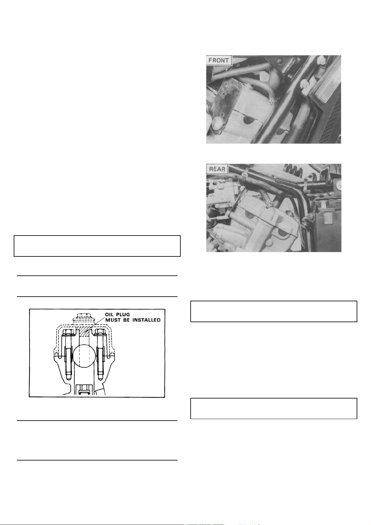
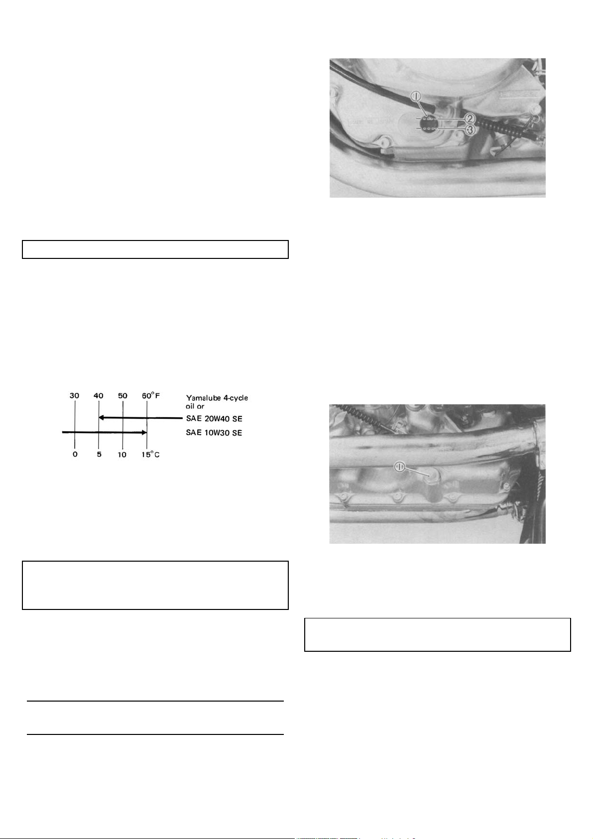
5. Remove the cylinder head covers.
NOTE:
Be careful so that the oil plugs on the camshaft caps
are not lost.
1. Oil plug
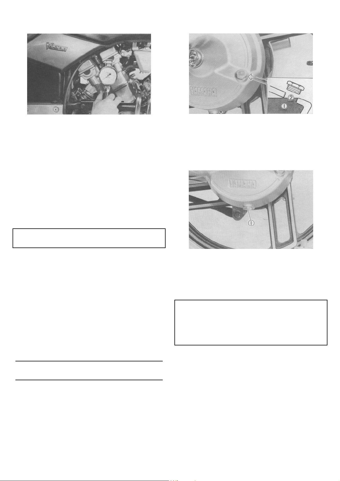
6. Remove the emblem plate and timing plug
from the left-side crankcase.
17
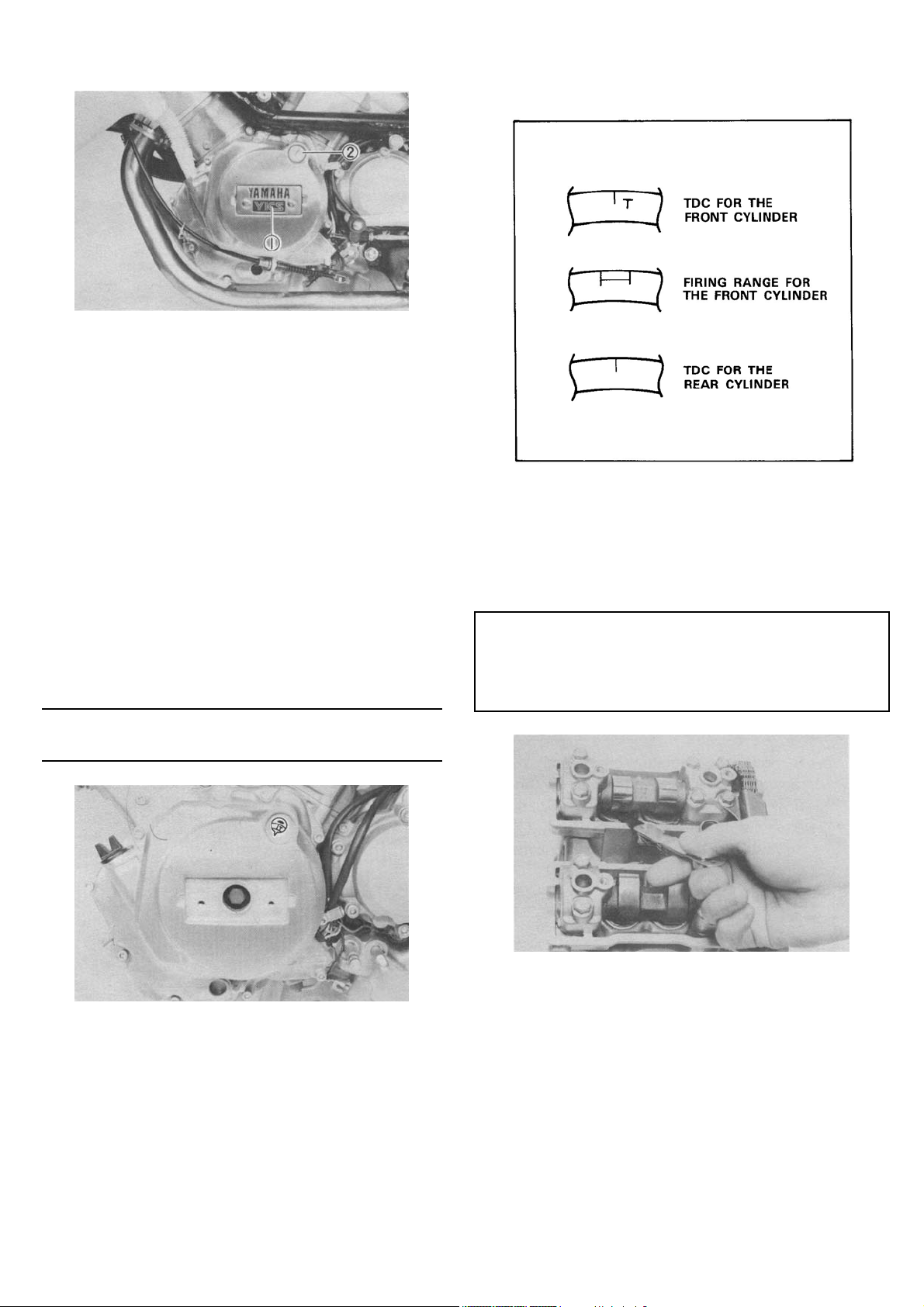
The flywheel is marked as follows:
1. Emblem plate 2. Timing plug
7. Align the "T" mark (for the front cylin-der)Vpn
the flywheel with the stationary pointer on
the crankcase cover. The pointer can be
viewed through the timing window in the
crankcase cover. When the "T" mark is
aligned with the stationary pointer, the piston
is at Top Dead Center (TDC). Valve clearance should be checked and adjusted when
the piston is at TDC on the compression
stroke. The piston is at TDC on compression
when there is free play in both valve adjusters.
NOTE:
The crankshaft should be turned counterclockwise,
as viewed from the left side of the motorcycle.
8. Use a feeler gauge to determine the clearance. If clearance is incorrect, record the
measured amount of clearance. This must
be measured carefully.
Intake valve (cold):
0.11 ~0.15mm (0.0043 -0.0059 in)
Exhaust valve (cold):
0.16 ~ 0.20mm (0.0063 ~ 0.0079 in)
9. Valve clearance is adjusted by replacing the
adjusting pad on the top of the valve lifter.
Adjusting pads are available in 25 thicknesses, ranging from No. 200 (2.00 mm
(0.079 in)) to No. 320 (3.20 mm (0.130 in) >
in steps of 0.05 mm (0.002 in). The thickness of each pad is marked on the pad face
that contacts the valve lifter (not the cam).
Adjustment of the valve clearance is accomplished as follows:
18
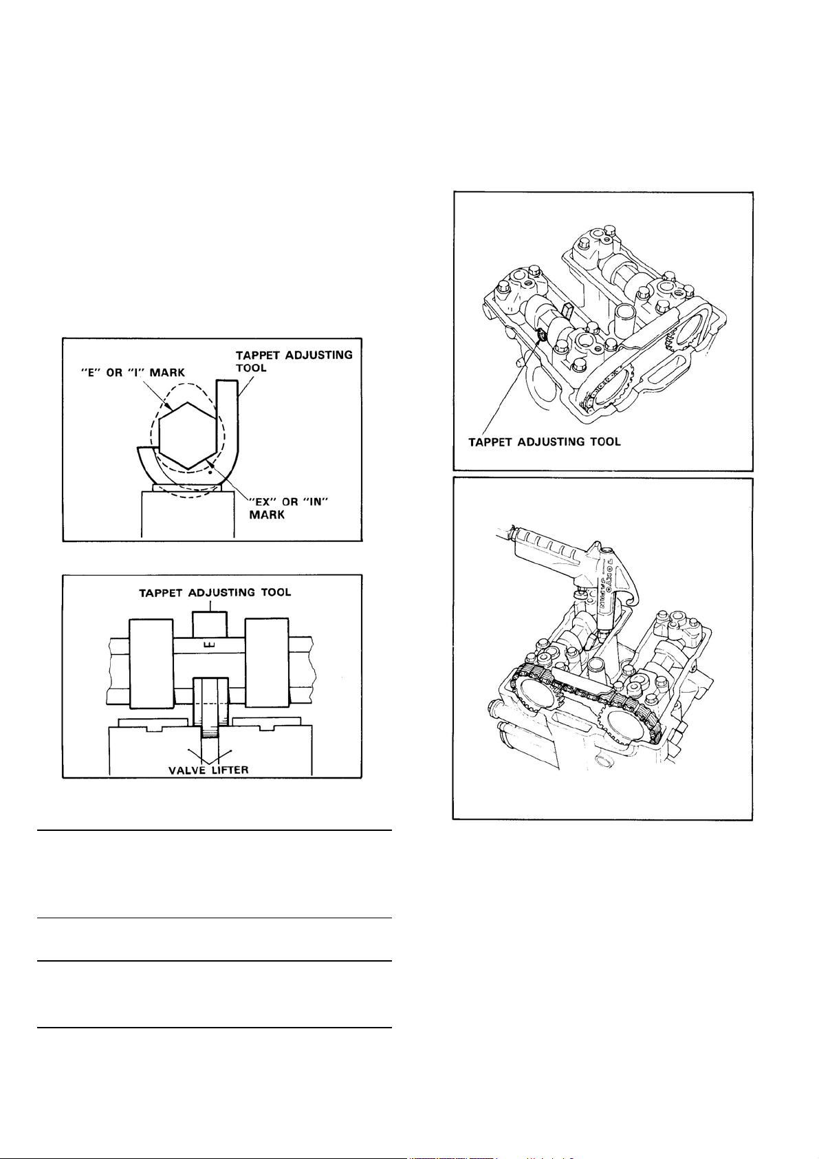
a. There is a slot in each valve lifter. The slots
must be positioned opposite of each other on
the exhaust and intake side before the tappet
adjusting tool is installed.
b. Turn the crankshaft until the camshaft identi-
fication mark (IN or EX) faces upward. Place
the tappet adjusting tool under the camshaft
with the tool match mark (•) and camshaft
I.D. mark aligned.
c. Turn the crankshaft until the lobe of the tool
depresses the valve lifters.
d. Remove the pads from the lifters. There is a
slot in each lifter. Use an air gun or a small
screwdriver and a magnetic rod to remove
the pads. Note the numbers on the pads.
WARNING:
When turning the crankshaft, exercise care so
that the tappet adjusting tool does not contact
the mating surface of the cylinder head and the
cylinder head cover.
NOTE:
When installing the tappet adjusting tool onto the
camshaft, be careful so that the lobe of the tool
does not ride on the pad.
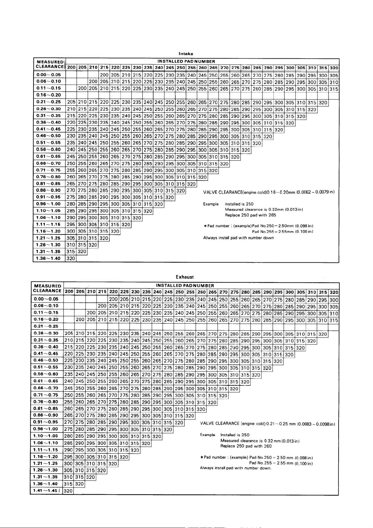
e. Proper pad selection is made as follows:
(Use appropriate chart for exhaust or intake
valves.)
1) Find number of original (installed) pad
number on chart. Read down on chart.
2) Find measured valve clearance (from
step 1) on chart. Read across.
19
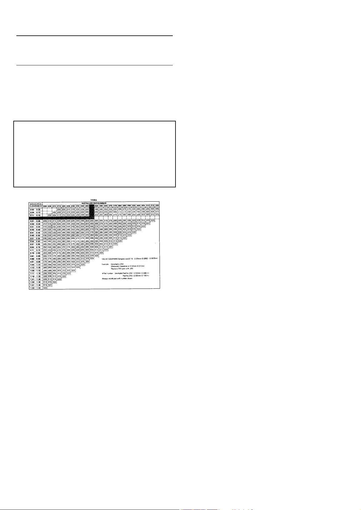
NOTE:
The new pad number is to be used as a guide only.
Verify the correctness of this choice in the following
step(s).
3) At the intersection of installed pad
number (down) and measured clearance (across) is a new pad number.
EXAMPLE:
Intake valve, installed pad:
No.250 (read down)
Measured clearance:
0.32mm (0.013 in) (read across)
New pad number: No.270
(intersection of down & across)
20
21
10. Install the new pad in the lifter. Install the
pad with the number down.
11. Turn the crankshaft to remove the adjusting
tool from the camshaft.
12. Turn the crankshaft to rotate cam several rotations. This will set the pad in the lifter.
13. Recheck the valve clearance. If the clearance is incorrect, repeat the proceeding
steps until the proper clearance is obtained.
14. To assemble the motorcycle, reverse the
disassembly procedures. Pay close attention
to installation of the cylinder head cover.
15. Rotate the crankshaft approximately 290 degrees counterclockwise to TDC for the rear
cylinder. Repeat the steps above, and
check/adjust the valve clearance.
Inspect the head cover gasket. If damaged,
replace the gasket.
16. Install the head covers, and torque the bolts
to specification.
Tightening torque:
10 Nm (1.0 m-kg, 7.2ft-lb)
WARNING:
When installing the cylinder head cover, make
sure all cam caps are covered with oil plugs.
NOTE:
The cylinder head cover should be so installed that
the smaller crankcase ventilation pipe fitting hole is
toward the front cylinder, and the larger one is toward the rear side.
17. Install the air baffle plate and radiator.
Tighten the radiator securing bolts to specification.
Tightening torque:
7 Nm (0.7m-kg, 5.1 ft-lb)
18. Install the radiator cover and air filter assembly. Connect the crankcase ventilation
pipes.
19. Install the fuel tank and connect the fuel and
vacuum pipe lines. Tighten the fuel tank holding bolt to specification.
Tightening torque:
15 Nm (1.5m-kg, 11 ft-lb)
22
Spark plug
1. Check electrode condition and wear, insulator color, and electrode gap.
2. Clean the spark plug with spark plug cleaner
if necessary. Use a wire gauge to adjust the
plug gap to specification.
3. If the electrode becomes too worn, replace
the spark plug.
4. When installing the plug, always clean the
gasket surface, wipe off any grime that might
be present on the surface of the spark plug,
and torque the spark plug properly.
Standard spark plug:
D8EA (NGK) or
X24ES-U(NIPPON DENSO)
Spark plug gap:
0.6-0.7 mm (0.024-0.028 in)
Spark plug tightening torque:
20 Nm (2.0 m-kg, 14 ft-lb)
NOTE:
Valve clearance must be set properly before synchronizing the carburetors.
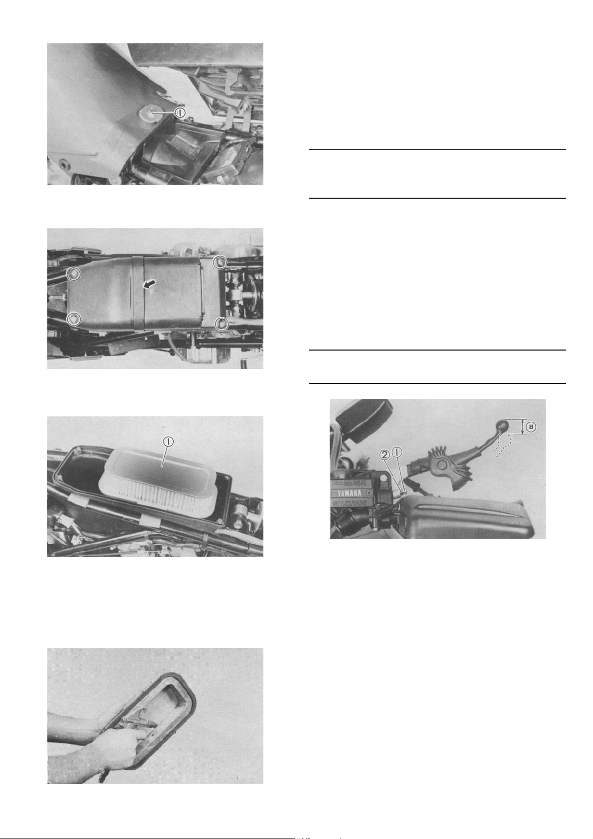
1. Remove the vacuum lines from each carburetor joint, and install the vacuum gauge
lines to each carburetor joint.
NOTE:
The front cylinder carburetor joint has two vacuum
lines coming out of it. Disconnect the smaller diameter line, and leave the larger line in place on the
carburetor joint.
Crankcase ventilation system Check the ventilation pipe from the cylinder head cover on the each cylinder to the air filter assembly for cracks or damage; replace if necessary.
Fuel line
Check the fuel hoses and vacuum lines for cracks or
damage; replace if necessary.
Exhaust system
1. Retighten the exhaust pipe flange bolts and
muffler clamp bolts.
Tightening torque:
Exhaust pipe flange bolt
10 Nm (1.0 m-kg, 7.2 ft-lb)
Muffler clamp bolt
20 Nm (2.0 m-kg, 14 ft-lb)
2. Turn the fuel cock to the "PRI" position.
3. Start the engine, and let it warm up.
4. Read the vacuum gauge. The readings for
each carburetor should be the same. If not,
adjust the synchronizing rod until the readings are the same.
2. Replace the exhaust pipe gasket(s) and/ or
muffler gasket(s) if necessary.
Carburetor synchronization Carburetors must be adjusted to open and close simultaneously. Adjust as follows:
1. Synchronizing rod
5. Reconnect the vacuum lines.
23
Idle speed
1. Start the engine, and warm it up for a few
minutes.
2. Set the engine idle speed to the specified
level by adjusting the throttle stop screw on
the rear cylinder carburetor. Turning the
throttle stop screw in (clockwise) increases
the engine speed; turning it out (counterclockwise) decreases the engine speed. Use
a tachometer for checking and adjusting the
engine speed.
Engine idle: 1,300 ± 50 r/min
Engine oil
Recommended oil
Use Yamalube 4-cycle oil or SAE 20W40 SE motor
oil if the temperature does not go below 5°C (40°F).
Use SAE 10W30SE motor oil if the temperature
does not go above 15°C (60° F).
1. Level window 2. Maximum mark 3. Minimum mark
3. The oil level should be between the maximum and minimum marks. If the level is
lower, add sufficient oil to raise it to the
proper level.
Oil change (without changing the filter)
1. Start the engine and stop after a few minutes
of warm-up.
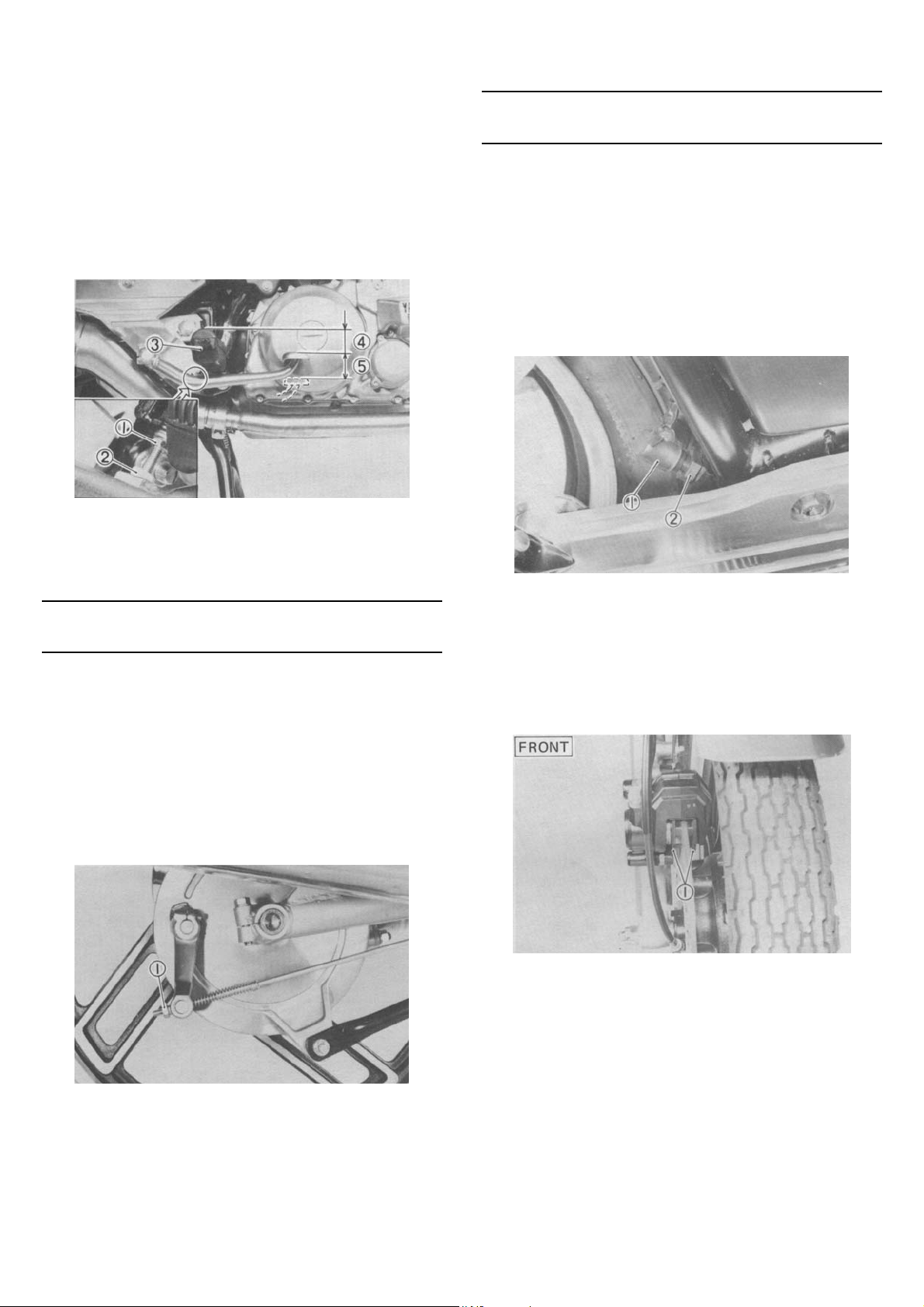
2. Place an oil pan under the engine and remove the oil filler cap.
3. Remove the drain plug and drain the oil.
Oil level measurement
1. Place the motorcycle on its center-stand.
Warm up the engine for several minutes.
NOTE:
Be sure the motorcycle is positioned straight up
when checking the oil level; a slight tilt toward the
side can produce false readings.
2. With the engine stopped, check the oil level
through the level window located at the
lower part of the left side crankcase cover.
NOTE:
Wait a few minutes until the oil level settles before
checking.
1. Engine drain plug
4. Reinstall the drain plug (make sure it is
tight).
Drain plug torque:
43 Nm (4.3 m-kg, 31.0 ft-lb)
24
5. Add 2.4 L (2.1 Imp qt, 2.5 US qt) of engine
oil through the oil filler hole. Reinstall the oil
filler cap.
CAUTION:
Take care not to allow foreign material to enter
the crankcase.
6. Start the engine, and let it warm up. During
warm-up, check for oil leakage. If oil leaks,
stop the engine immediately, and check for
the cause.
7. Stop the engine and check the oil level.
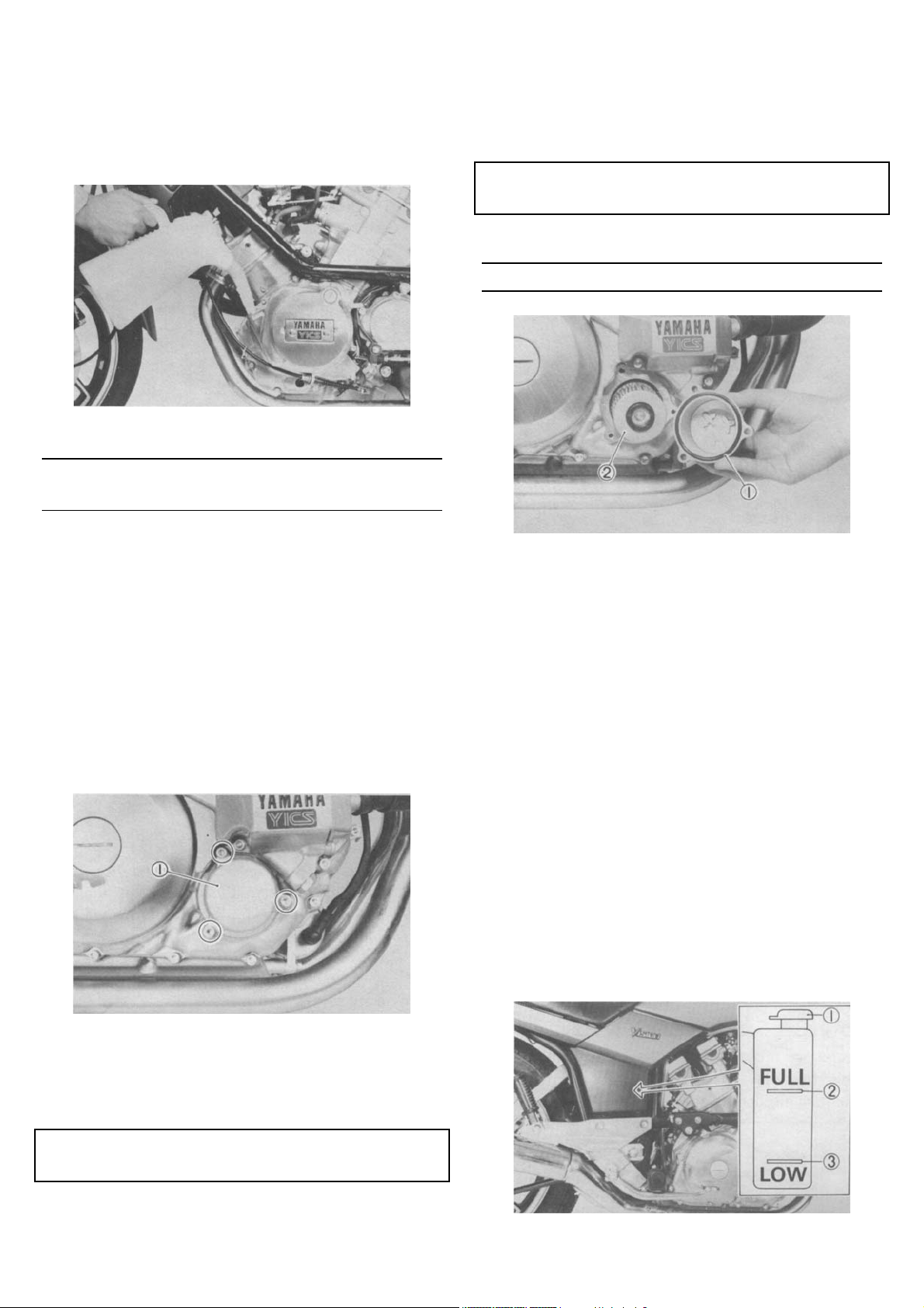
Oil and filter change
1. Remove the drain plug and drain the oil.
2. Remove the oil filter bolt and filter element
1. Oil filter cover
3. Reinstall the drain plug (make sure it is
tight).
4. Install the new oil filter element, new O-ring,
and filter cover; tighten the oil filter bolt.
Oil filter bolt:
10 Nm 1.0 m-kg, 7.2ft-lb)
NOTE:
Make sure the O-ring is positioned properly.
1. Proper O-ring position 2. Oil filter element
5. Add. 2.7 L (2.4 Imp qt, 2.9 US qt) of engine
oil through the oil filler. Reinstall the oil filler
cap.
6. After the replacement of engine oil and/or oil
filter, be sure to check for the oil level and
any oil leakage. The oil level indicator light
should go off after the oil is filled.
Coolant Check the coolant level in the reservoir tank when the engine is cold. The coolant level is satisfactory if it is between the FULL and LOW level on the tank. The coolant level will vary with engine temperature. However, if the level is on or below the LOW level, add tap water (soft water) until the "FULL" level is reached. Change the coolant every two years. (See "COOLING SYSTEM" for more detail.)
Drain plug torque:
43 Nm (4.3 m-kg, 31.0 ft-lb)
1. Coolant reservoir tank cap 2. Full level 3. Low level
25
WARNING:
Do not remove the radiator cap when the engine
is hot.
CAUTION:
Hard water or salt water is harmful to the engine
parts.
You may use boiled water or distilled water if
you can't get soft water.
Reservoir tank capacity:
Total:
0.35 L(0.3 Impqt, 0.4 US qt)
From LOW to FULL level:
0.25 L(0.2 Impqt, 0.3 US qt)
Clutch adjustment Free play adjustment
1. Loosen the clutch lever adjuster lock-nut.
2. Turn the cable adjuster either in or out until
proper lever free play is attained. Tighten the
locknut.
Mechanism adjustment
1. Fully loosen the cable inner wire lengthadjuster locknut and screw in the adjuster
until tight.
2. Turn the handle lever adjuster in.
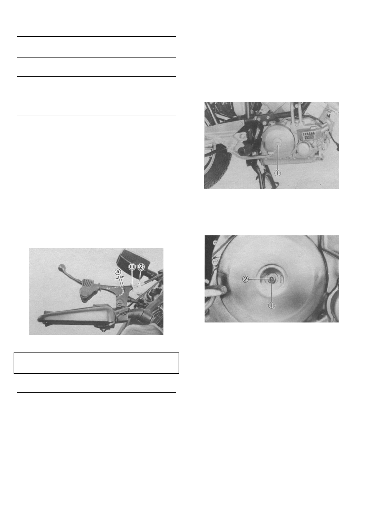
3. Remove the clutch adjuster plug from the
right side crankcase cover.
1. Clutch adjuster plug
4. Loosen the adjuster lock nut on the pressure plate.
1. Locknut 2. Adjuster a. 2~3 mm (0.08-0.12 in)
Clutch lever free play:
2 ~3 mm (0.08 ~0.12 in)
NOTE:
The above procedure provides for maximum cable
free play to allow for proper clutch actuating mechanism adjustment.
1. Adjuster 2. Locknut
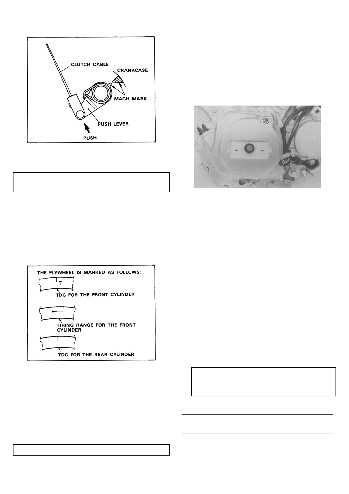
5. Move the push lever toward the front with
your finger until it stops. With the push lever
in this position, back out the adjusting screw,
and as illustrated, align the mark on the end
of the push lever with the mark (protuberance) on the crankcase.
26
6. Tighten the adjuster lockout.
Tightening torque:
8 Nm (0.8 m-kg, 5.8ft-lb)
7. Adjust the clutch lever free play.
Checking ignition timing Check the ignition timing with a timing light by observing the stationary pointer and the marks stamped on the flywheel.
1. Remove the emblem plate and timing plug
from the left side crankcase cover.
2. Connect the timing light to the front (#1) cyl-
inder spark plug wire.
3. Start the engine, and keep the engine running at the specified speed. Use a tachometer to check the engine speed.
Engine Speed: 1,300 ± 50 r/min
4. The stationary pointer (in the timing window)
should be within the firing range shown on
the flywheel. If the pointer is not within the
range or if it is not steady, check the flywheel
and/or pickup assembly for tightness and/or
damage. (See Chapter 7, "ELECTRICAL" for
further information.)
5. Reinstall the generator cover.
Compression pressure measurement
Insufficient compression pressure will result in performance loss and may indicate leaking valves or
worn or damaged piston rings.
1. Make sure the valve clearance is correct.
2. Warm up the engine for 2 ~ 3 minutes; stop
the engine.
3. Remove both spark plugs.
4. Install a compression gauge.
5. Turn over the engine with the electric starter
(make sure the battery is fully charged) with
the throttle wide open until the pressure indicated on the gauge does not increase further. The compression should be within the
specified levels.
Compression pressure (at seal level):
Standard: 980 kPa (10 kg/cm2, 142 psi)
Minimum: 882 kPa (9 kg/cm2, 128 psi)
Maximum: 1,079 kPa (11 kg/cm2,156 psi)
WARNING:
When cranking the engine, ground the spark
plug wires to prevent sparking.
27
6. If the pressure is too low, squirt a few drops
of oil into the cylinder being measured.
Measure compression again. If there is a
higher reading than before (without oil), the
piston rings may be worn or damaged. If the
pressure remains the same after measuring
with the oil, one or both rings and valves
may be the source of the problem.
7. Check both cylinders. Compression pressure
should not vary more than the specified
value from one cylinder to the other.
Difference between each cylinder:
Less than 98 kPa (1.0 kg/cm2, 14 psi)
CHASSIS
Final gear oil
Oil level measurement
1. Place the motorcycle on a level place, and
place it on its centerstand. The engine
should be cool (at atmospheric temperature).
2. Remove the oil filler cap and check the oil
level. If it is not up to the brim of the filler
hole, add oil.
CAUTION:
Take care not to allow foreign material to enter
the final gear case.
1. Final gear oil 2. Correct oil level
Gear oil replacement
1. Place an oil pan under the final gear case.
2. Remove the final gear oil filler cap and the
drain plug; drain the oil.
1. Final gear drain plug
3. Reinstall and tighten the final gear drain
plug.
4. Fill the gear case to the specified level.
Oil capacity: 0.20 L (0.18 Imp qt, 0.21 US qt)
Recommended oil: SAE 80 API "GL-4"
Hypoid gear oil
If desired, an SAE 80W90 Hypoid gear oil may be
used for all conditions.
5. Reinstall the filler cap securely.
Air filter
1. Turn the fuel cock lever to "RES". Remove
the fuel pipes from the fuel cock.
2. Remove the sidecovers.
3. Open the seat and remove the fuel tank
holding bolt.
28
1. Fuel tank holding bolt
4. Remove the band and air filter case cover by
removing the four screws.
7. Reassemble by reversing the removal procedure. Check whether the element is
seated completely against the case.
8. The air filter element should be cleaned at
the specified intervals.
CAUTION:
The engine should never be run without the air
cleaner element installed; excessive piston
and/or cylinder wear may result.
Front and rear brake
Front brake lever free play adjustment. The brake
can be adjusted by simply adjusting the free play of
the brake lever. The piston in the caliper moves
forward as a brake pad wears out, automatically
adjusting the clearance between the brake pads and
brake disc.
CAUTION:
5. Pull out the element.
1. Air filter element
6. Tap the element lightly to remove most of
the dust and dirt; then blow out the remaining dirt with compressed air from the inner
surface of the element. If element is damaged, replace it.
Proper lever free play is essential to avoid excessive brake drag.
1. Adjuster 2. Locknut @ 5~8mm (0.2~0.3 in)
1. Loosen the adjuster locknut on the brake
lever.
2. Turn the adjuster so that the brake lever
movement at the lever end is 5 ~ 8mm (0.2 ~
0.3 in) before the adjuster contacts the master cylinder piston.
3. After adjusting, tighten the locknut.
29
Rear brake pedal height adjustment
1. Loosen the adjuster locknut (for pedal
height).
2. By turning the adjuster bolt clockwise or
counterclockwise, adjust the brake pedal position so that its top end is flush with the top
of the footrest.
3. Secure the adjuster locknut.
WARNING:
Check the operation of the brake light after adjusting the rear brake.
Brake light switch adjustment
The brake light switch is operated by the movement
of the brake pedal. To adjust, hold the switch body
with your hand so it does not rotate and turn the
adjusting nut. Proper adjustment is achieved when
the brake light comes on slightly before the brake
begins to take effect.
1. Adjuster bolt 3. Footrest
(for pedal height) 4. Pedal height 20mm (0.8 in)
2. Locknut 5. Free play 15 -25 mm (0.6 ~1.0 in)
WARNING:
After adjusting the pedal height, the brake-pedal
free play should be adjusted.
Free play
1. The rear brake should be adjusted to suit the
rider's preference, but free play at the end of
the brake pedal should be 15 ~25mm (0.6 ~
1.0 in). To adjust, turn the adjuster on the
brake rod clockwise to reduce play; turn the
adjuster counterclockwise to increase play.
1. Main body 2. Adjusting nut
Front brake pad
To check, examine the pads in the front brake. If
any pad is worn to the wear limit, replace both pads
in the caliper.
1. Wear indicator
1. Adjuster
30
 Loading...