

Yamaha XVS650, XVS650A User Manual

OWNER’S MANUAL
XVS650
XVS650A
4VR-28199-E3

40
4
INTRODUCTION
EAU00001
Welcome to the Yamaha world of motorcycling!
40
As the owner of a XVS650/XVS650A, you are benefiting from Yamaha’s vast experience in and newest technology for the design and the manufacture of high-quality products, which have earned Yamaha a reputation for dependability.
Please take the time to read this manual thoroughly, so as to enjoy all your
XVS650/XVS650A’s advantages. The owner’s manual does not only instruct you in
how to operate, inspect and maintain your motorcycle, but also in how to safeguard
yourself and others from trouble and injury.
In addition, the many tips given in this manual will help to keep your motorcycle in the
best possible condition. If you have any further questions, do not hesitate to contact
your Yamaha dealer.
The Yamaha team wishes you many safe and pleasant rides. So, remember to put
safety first!
3
40
40
40
40
40
9
40
40

IMPORTANT MANUAL INFORMATION
Particularly important information is distinguished in this manual by the following notations:
4
EAU00005
4
The Safety Alert Symbol means ATTENTION! BECOME ALERT! YOUR SAFETY
IS INVOLVED!
3
WARNING
4
Failure to follow WARNING instructions could result in severe injury or death to the
motorcycle operator, a bystander or a person inspecting or repairing the motorcycle.
4
CAUTION:
4
4
NOTE:
A CAUTION indicates special precautions that must be taken to avoid damage to
the motorcycle.
A NOTE provides key information to make procedures easier or clearer.
4
NOTE:
This manual should be considered a permanent part of this motorcycle and should remain with
9
4
4
●
it even if the motorcycle is subsequently sold.
Yamaha continually seeks advancements in product design and quality. Therefore, while this
●
manual contains the most current product information available at the time of printing, there may
be minor discrepancies between your motorcycle and this manual. If there is any question concerning this manual, please consult your Yamaha dealer.
4
IMPORTANT MANUAL INFORMATION
EW000002
WARNING
PLEASE READ THIS MANUAL CAREFULLY AND COMPLETELY BEFORE OPERATING THIS
MOTORCYCLE.
40
40
3
40
40
40
40
40
9
40
40
4
4
3
4
4
4
4
4
1999 by Yamaha Motor Co., Ltd.
9
All rights reserved. Any reprinting or
4
unauthorized use without the written
permission of Yamaha Motor Co., Ltd.
4
XVS650/XVS650A
OWNER’S MANUAL
1st Edition, May 1999
is expressly prohibited.
Printed in Japan.
EAU00008
1
2
3
4
5
6
7
8
9
EAA30002
EAU00009
TABLE OF CONTENTS
1 GIVE SAFETY THE RIGHT OF WAY
2 DESCRIPTION
3 INSTRUMENT AND CONTROL FUNCTIONS
4 PRE-OPERATION CHECKS
5 OPERATION AND IMPORTANT RIDING POINTS
6 PERIODIC MAINTENANCE AND MINOR REPAIR
7 MOTORCYCLE CARE AND STORAGE
8 SPECIFICATIONS
9 CONSUMER INFORMATION
INDEX

GIVE SAFETY THE RIGHT OF WAY
GIVE SAFETY THE RIGHT OF WAY ................................................ 1-1
1
GIVE SAFETY THE RIGHT OF WAY
GIVE SAFETY THE RIGHT OF WAY
Motorcycles are fascinating vehicles, which can give you an unsurpassed feeling of power and freedom.
However, they also impose certain limits, which you must accept; even the best motorcycle does not ig-
1
2
3
4
5
6
7
8
9
nore the laws of physics.
Regular care and maintenance are essential for preserving your motorcycle’s value and operating condition. Moreover, what is true for the motorcycle is also true for the rider: good performance depends on being in good shape. Riding under the influence of medication, drugs and alcohol is, of course, out of the
question. Motorcycle riders – more than car drivers – must always be at their mental and physical best.
Under the influence of even small amounts of alcohol, there is a tendency to take dangerous risks.
Protective clothing is as essential for the motorcycle rider as seat belts are for car drivers and passengers.
Always wear a complete motorcycle suit (whether made of leather or tear-resistant synthetic materials
with protectors), sturdy boots, motorcycle gloves and a properly fitting helmet. Optimum protective wear,
however, should not encourage carelessness. Though full-coverage helmets and suits, in particular, create an illusion of total safety and protection, motorcyclists will always be vulnerable. Riders who lack critical self-control run the risk of going too fast and are apt to take chances. This is even more dangerous in
wet weather. The good motorcyclist rides safely, predictably and defensively – avoiding all dangers, including those caused by others.
EAU00021
Enjoy your ride!
GIVE SAFETY THE RIGHT OF WAY
1-1

DESCRIPTION
Left view (XVS650)............................................................................ 2-1
Right view (XVS650).......................................................................... 2-2
Left view (XVS650A).......................................................................... 2-3
Right view (XVS650A) ....................................................................... 2-4
Controls/Instruments (XVS650/XVS650A)......................................... 2-5
2

DESCRIPTION
Left view (XVS650)
1
2
2
4
5
6
7
8
1.Shift pedal (page 3-5)
2.Fuel cock (page 3-8)
9
3.Starter (choke) “ ” (page 3-9)
4.Rear shock absorber spring preload adjusting ring (page 3-14)
5.Helmet holder (page 3-12)
6.Storage compartment (page 3-13)
7.Tool kit (page 6-1)
EAU00026
2-1
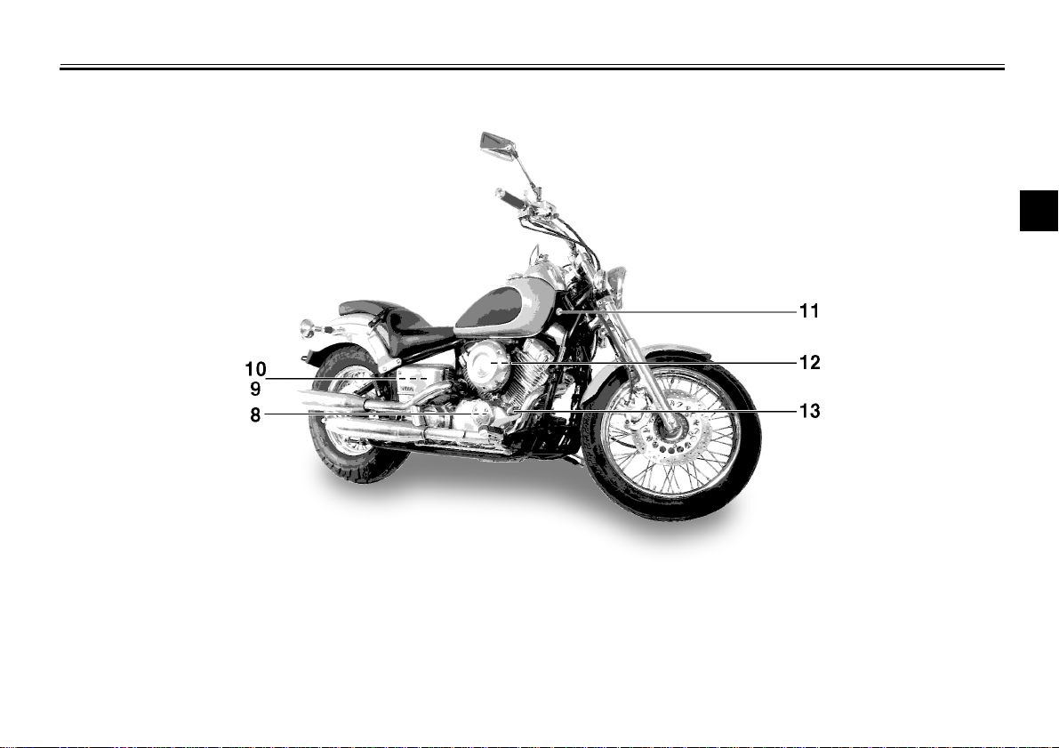
Right view (XVS650)
DESCRIPTION
1
2
2
4
5
6
7
8.Oil filter (page 6-10)
9.Battery (page 6-26)
10.Fuses (page 6-27)
11.Main switch (page 3-1)
12.Air filter (page 6-12)
13.Rear brake pedal (page 3-6)
8
9
2-2

DESCRIPTION
Left view (XVS650A)
1
2
2
4
5
6
7
8
1.Shift pedal (page 3-5)
9
2.Fuel cock (page 3-8)
3.Starter (choke) “ ” (page 3-9)
4.Rear shock absorber spring preload adjusting ring (page 3-14)
5.Helmet holder (page 3-12)
6.Storage compartment (page 3-13)
7.Tool kit (page 6-1)
2-3
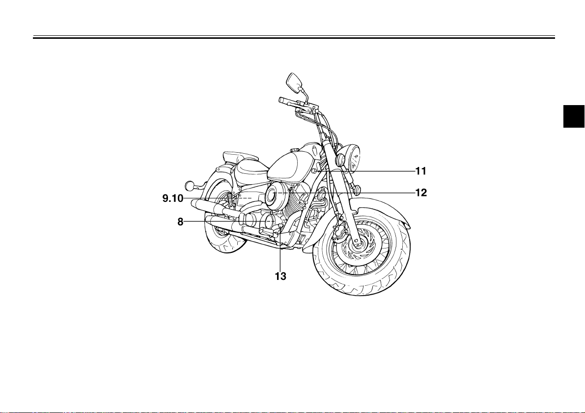
Right view (XVS650A)
DESCRIPTION
1
2
2
4
5
6
7
8.Oil filter (page 6-10)
9.Battery (page 6-26)
10.Fuses (page 6-27)
11.Main switch (page 3-1)
12.Air filter (page 6-12)
13.Rear brake pedal (page 3-6)
8
9
2-4
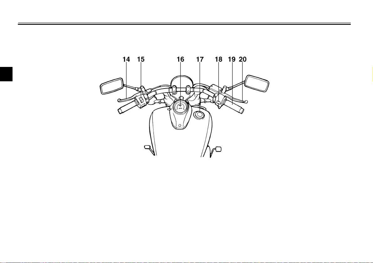
DESCRIPTION
Controls/Instruments (XVS650/XVS650A)
1
2
2
4
5
6
7
8
14.Clutch lever (page 3-5)
15.Left handlebar switches (page 3-3)
9
16.Speedometer (page 3-2)
17.Fuel tank cap (page 3-6)
18.Right handlebar switches (page 3-4)
19.Throttle grip (page 6-15)
20.Front brake lever (page 3-5)
2-5
INSTRUMENT AND CONTROL FUNCTIONS
Main switch/Steering lock...................................................................3-1
Indicator lights.................................................................................... 3-2
Speedometer ..................................................................................... 3-2
Antitheft alarm (optional).................................................................... 3-3
Handlebar switches............................................................................ 3-3
Clutch lever........................................................................................ 3-5
Shift pedal.......................................................................................... 3-5
Front brake lever................................................................................3-5
Rear brake pedal................................................................................3-6
Fuel tank cap ..................................................................................... 3-6
Fuel.................................................................................................... 3-7
Fuel tank breather hose..................................................................... 3-7
Fuel cock............................................................................................ 3-8
Starter (choke) “ ” .......................................................................... 3-9
Seats (for XVS650)............................................................................ 3-9
Seats (for XVS650A)........................................................................ 3-11
Helmet holder................................................................................... 3-12
Storage compartment ...................................................................... 3-13
Rear shock absorber adjustment..................................................... 3-14
Luggage strap holders..................................................................... 3-15
Sidestand......................................................................................... 3-15
Sidestand/clutch switch operation check......................................... 3-16
3
ON
INSTRUMENT AND CONTROL FUNCTIONS
1
2
3
EAU00029
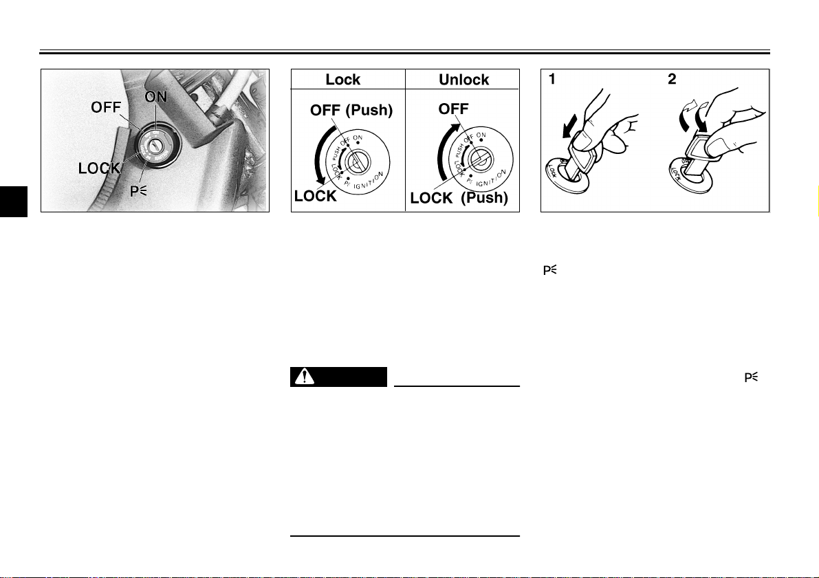
Main switch/Steering lock
4
The main switch controls the ignition
and lighting systems. Its operation is
5
described below.
6
Electrical circuits are switched on. The
engine can be started. The key cannot
7
be removed in this position.
8
OFF
All electrical circuits are switched off.
9
The key can be removed in this position.
LOCK
The steering is locked in this position
and all electrical circuits are switched off.
EAU00036
EAU00038
EAU00040
The key can be removed in this position. To lock the steering, turn the handlebars all the way to the left. While
pushing the key into the main switch,
turn it from “OFF” to “LOCK” and remove it. To release the lock, turn the
key to “OFF” while pushing.
WARNING
Never turn the key to “OFF” or
“LOCK” when the motorcycle is
moving. The electrical circuits will
be switched off which may result in
loss of control or an accident. Be
sure the motorcycle is stopped before turning the key to “OFF” or
“LOCK”.
EW000016
EAU00027
1. Push
2. Turn
EAU00044
(Parking)
The steering is locked in this position
and the taillight comes on, but all other
circuits are off. The key can be removed in this position.
To use the parking position, first lock
the steering, then turn the key to “ ”.
Do not use this position for an extended length of time as the battery may
discharge.
3-1
INSTRUMENT AND CONTROL FUNCTIONS
EAU00063
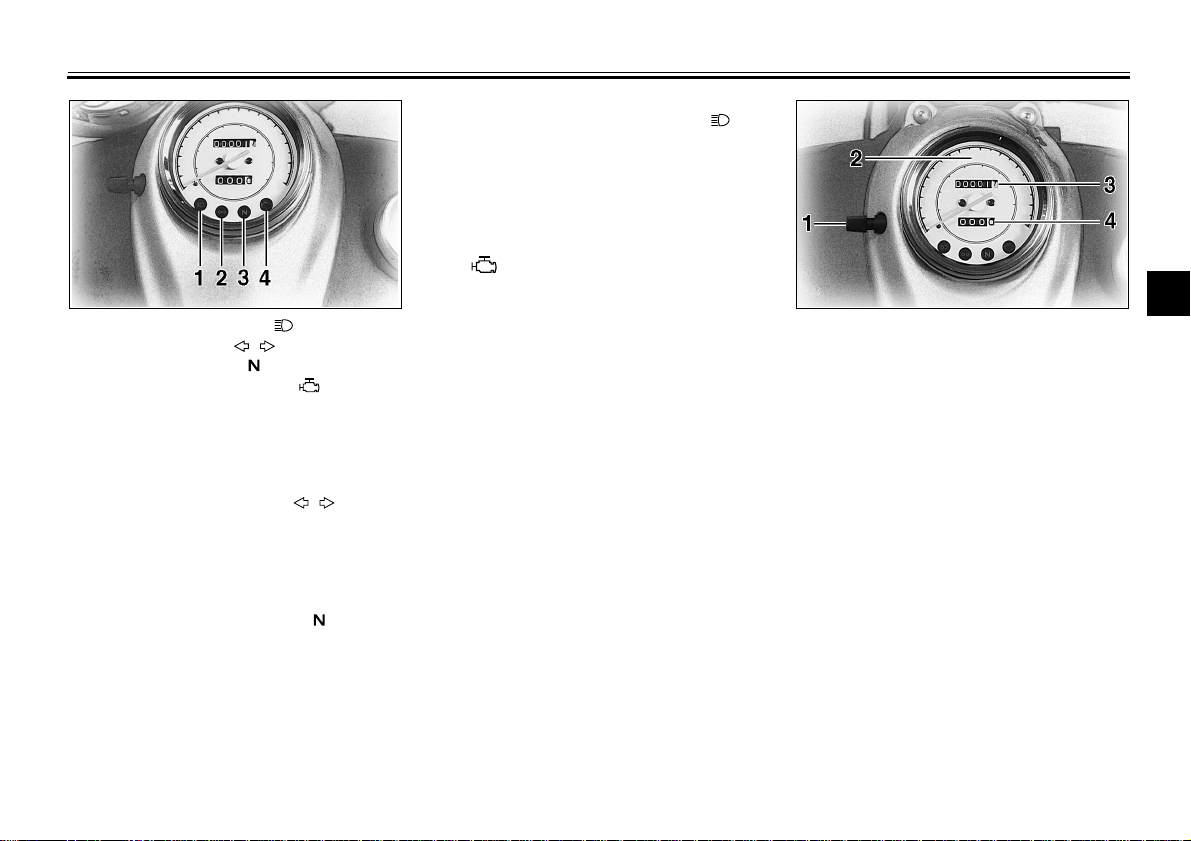
3. High beam indicator light “ ”
This indicator comes on when the
headlight high beam is used.
1
1. High beam indicator light “ ”
2. Turn indicator light “ ”
3. Neutral indicator light “ ”
4. Engine trouble indicator light “ ”
EAU00056
Indicator lights
EAU00057
1. Turn indicator light “ ”
This indicator flashes when the turn
switch is moved to the left or right.
EAU00061
2. Neutral indicator light “ ”
This indicator comes on when the
transmission is in neutral.
EAU00091
4. Engine trouble indicator light
“”
This indicator light will come on or flash
if trouble occurs in a monitoring circuit.
In such a case, take the motorcycle to
a Yamaha dealer to have the self-diagnostic systems checked.
1. Reset knob
2. Speedometer
3. Odometer
4. Trip odometer
EAU00095
Speedometer
The speedometer shows riding speed.
This speedometer is equipped with an
odometer and trip odometer. The trip
odometer can be reset to “0” with the
reset knob. Use the trip odometer to
estimate how far you can ride on a
tank of fuel. This information will enable you to plan fuel stops in the future.
2
3
4
5
6
7
8
9
3-2
INSTRUMENT AND CONTROL FUNCTIONS
Antitheft alarm (optional)
An antitheft alarm can be equipped to
this motorcycle. Consult your Yamaha
1
dealer to obtain and install the alarm.
2
3
4
5
6
7
8
9
EAU00109
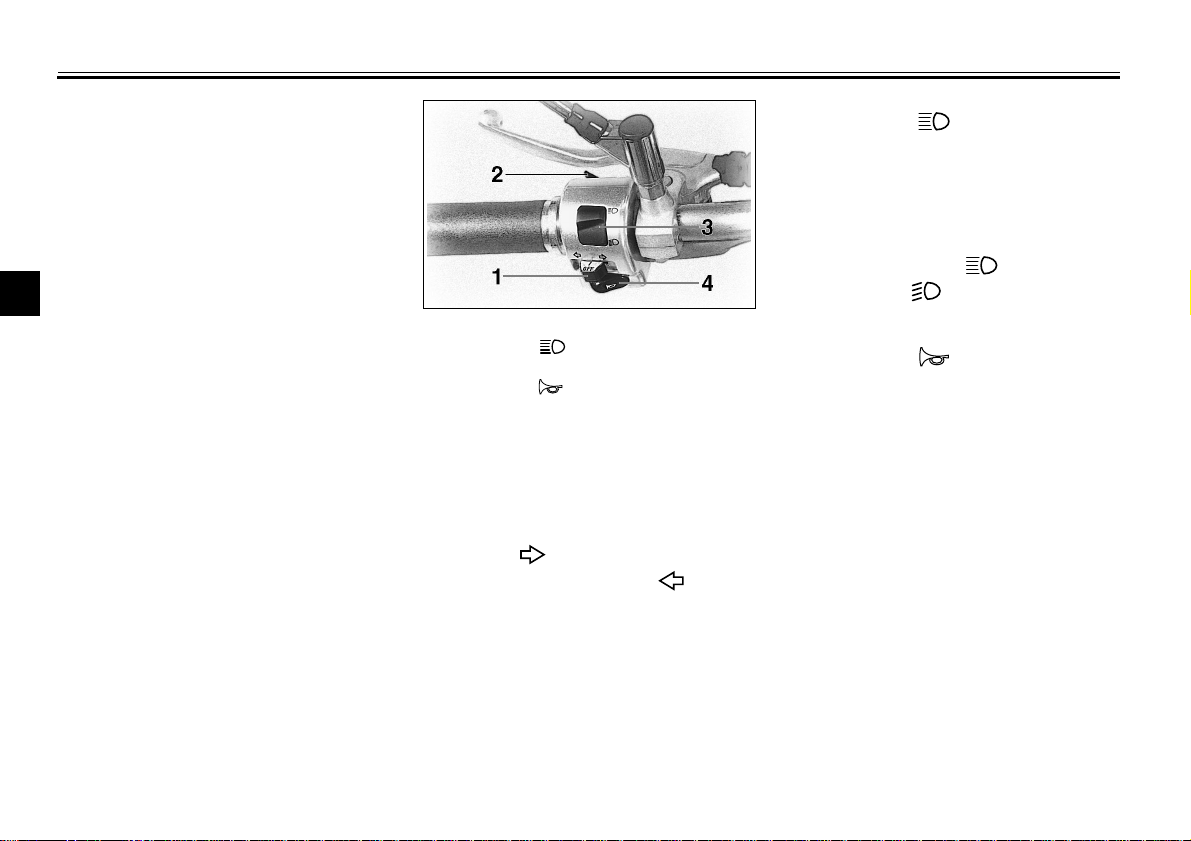
1. Turn signal switch
2. Pass switch “ ”
3. Dimmer switch
4. Horn switch “ ”
EAU00118
Handlebar switches
EAU00127
Turn signal switch
To signal a right-hand turn, push the
switch to “ ”. To signal a left-hand
turn, push the switch to “ ”. Once
the switch is released it will return to
the center position. To cancel the signal, push the switch in after it has returned to the center position.
EAU00119
Pass switch “ ”
Press the switch to operate the passing light.
EAU00121
Dimmer switch
Turn the switch to “ ” for the high
beam and to “ ” for the low beam.
EAU00129
Horn switch “ ”
Press the switch to sound the horn.
3-3
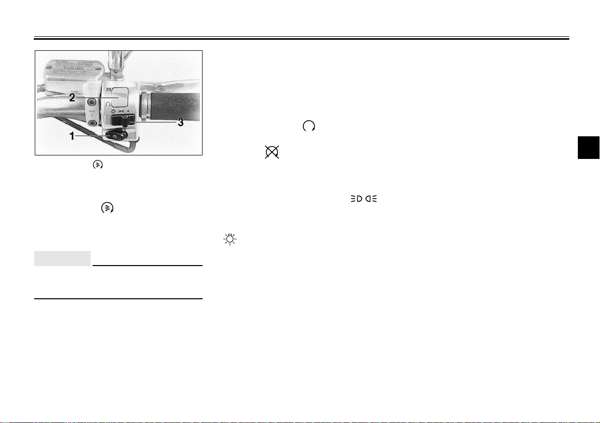
1. Start switch “ ”
2. Engine stop switch
3. Lights switch
EAU00143
Start switch “ ”
The starter motor cranks the engine
when pushing the start switch.
EC000005
CAUTION:
See starting instructions prior to
starting the engine.
INSTRUMENT AND CONTROL FUNCTIONS
Engine stop switch
The engine stop switch is a safety device for use in an emergency such as
when the motorcycle overturns or if
trouble occurs in the throttle system.
Turn the switch to “ ” to start the engine. In case of emergency, turn the
switch to “ ” to stop the engine.
Lights switch
Turning the light switch to “ ”,
turns on the auxiliary light, meter lights
and taillight. Turning the light switch to
“ ”, turns the headlight on also.
EAU00138
EAU00134
1
2
3
4
5
6
7
8
3-4
9
INSTRUMENT AND CONTROL FUNCTIONS
1
2
3
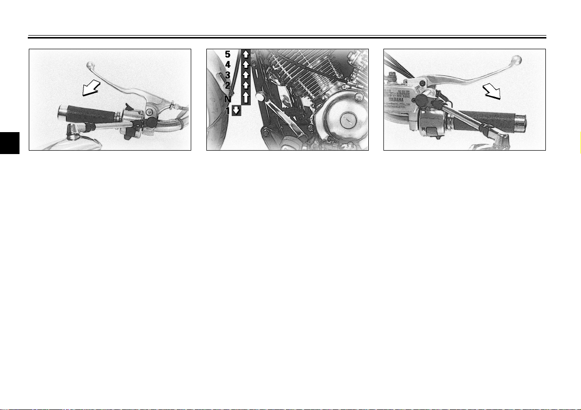
EAU00152
Clutch lever
4
The clutch lever is located on the left
handlebar, and the ignition circuit cut-
5
off system is incorporated in the clutch
lever holder. Pull the clutch lever to the
6
handlebar to disengage the clutch, and
release the lever to engage the clutch.
7
The lever should be pulled rapidly and
released slowly for smooth clutch op-
8
eration. (Refer to the engine starting
procedures for a description of the ig-
9
nition circuit cut-off system.)
Shift pedal
This motorcycle is equipped with a
constant-mesh 5-speed transmission.
The shift pedal is located on the left
side of the engine and is used in combination with the clutch when shifting.
EAU00157
EAU00158
Front brake lever
The front brake lever is located on the
right handlebar. Pull it toward the handlebar to apply the front brake.
3-5
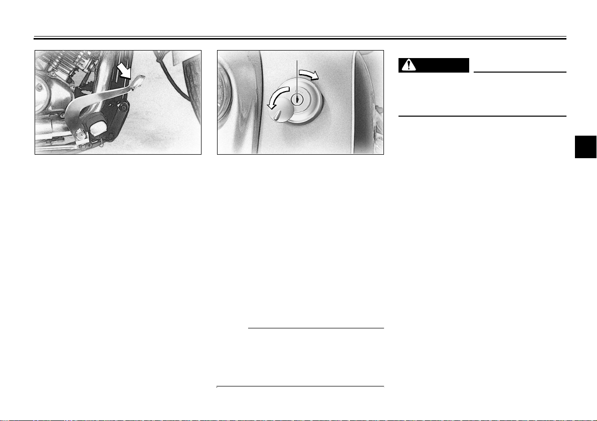
EAU00162
Rear brake pedal
The rear brake pedal is on the right
side of the motorcycle. Press down on
the brake pedal to apply the rear
brake.
INSTRUMENT AND CONTROL FUNCTIONS
WARNING
Be sure the cap is properly installed
and locked in place before riding
the motorcycle.
EAU00167
Fuel tank cap
To open
Insert the key and turn it 1/4 turn clockwise. The lock will be released and the
cap can be opened.
EW000023
1
2
3
4
5
6
To close
Push the tank cap into position with the
key inserted. To remove the key, turn it
counterclockwise to the original position.
NOTE:
This tank cap cannot be closed unless
the key is in the lock. The key cannot
be removed if the cap is not locked
properly.
3-6
7
8
9
INSTRUMENT AND CONTROL FUNCTIONS
CAUTION:
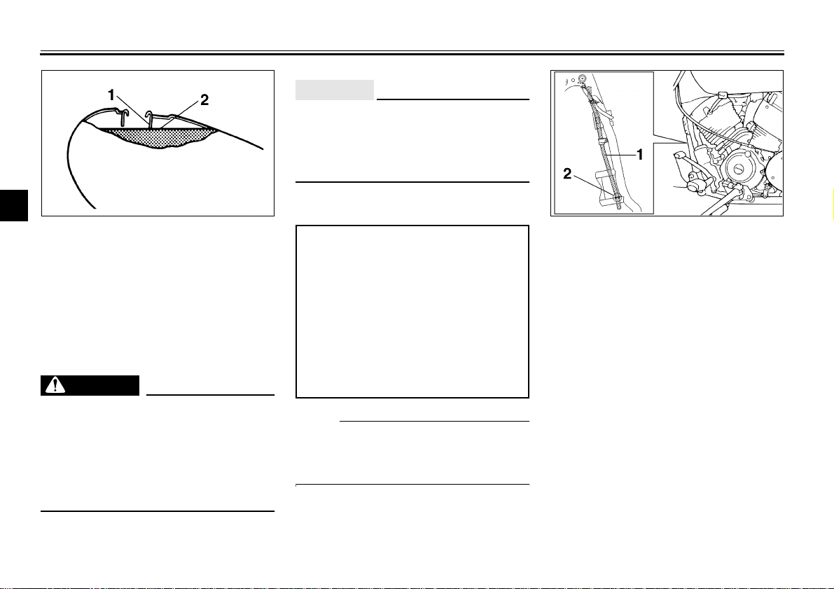
EAU00185
1
2
3
1. Filler tube
2. Fuel level
4
Fuel
5
Make sure there is sufficient fuel in the
tank. Fill the fuel tank to the bottom of
6
the filler tube as shown in the illustration.
7
WARNING
8
Do not overfill the fuel tank. Avoid
spilling fuel on the hot engine. Do
not fill the fuel tank above the bot-
9
tom of the filler tube or it may overflow when the fuel heats up later
and expands.
EAU01183
EW000130
Always wipe off spilled fuel immediately with a dry and clean soft cloth.
Fuel may deteriorate painted surfaces or plastic parts.
EAU00191
Recommended fuel:
Regular unleaded gasoline with
a research octane number of 91
or higher.
Fuel tank capacity:
Total:
16 L
Reserve:
3 L
NOTE:
If knocking or pinging occurs, use a different brand of gasoline or higher octane grade.
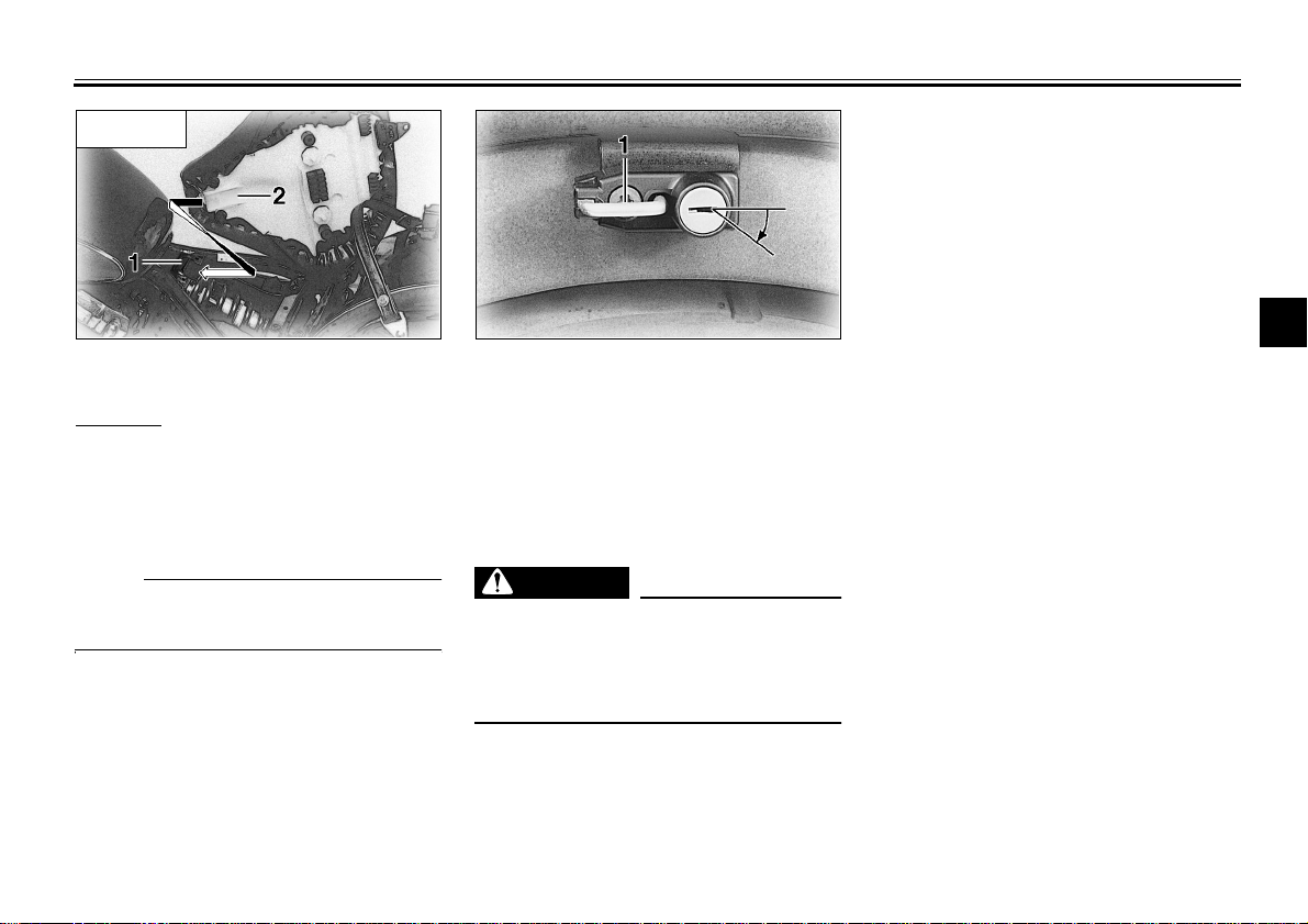
1. Fuel tank breather hose
2. Guide
EAU02955
Fuel tank breather hose
This model is equipped with a fuel tank
breather hose.
Before using this motorcycle:
Check the fuel tank breather hose
●
connection.
Check the fuel tank breather hose
●
for cracks or damage and replace
it if damaged.
Make sure the end of the fuel tank
●
breather hose is not blocked and
clean it if necessary.
3-7
ON
INSTRUMENT AND CONTROL FUNCTIONS
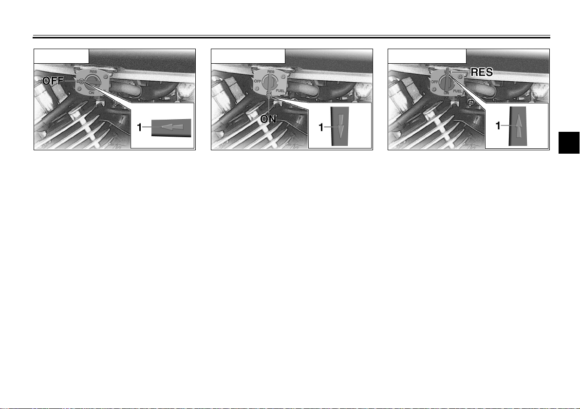
Off position
1. Arrow mark positioned over “OFF”
EAU02969
Fuel cock
The fuel cock supplies fuel from the
tank to the carburetors while filtering it
also.
The fuel cock has three positions,
which should be set as shown in the illustrations.
OFF
With the fuel cock in this position, fuel
will not flow. Always set the fuel cock to
this position when the engine is not
running.
Normal position
1. Arrow mark positioned over “ON”
With the fuel cock in this position, fuel
flows to the carburetors. Set the fuel
cock to this position when starting the
engine and while riding.
Reserve position
1. Arrow mark positioned over “RES”
RES
This indicates reserve. If you run out of
fuel while riding, set the fuel cock to
this position. Fill the tank at the first opportunity. Be sure to set the fuel cock
back to “ON” after refueling!
1
2
3
4
5
6
7
8
9
3-8
INSTRUMENT AND CONTROL FUNCTIONS
1
2
3
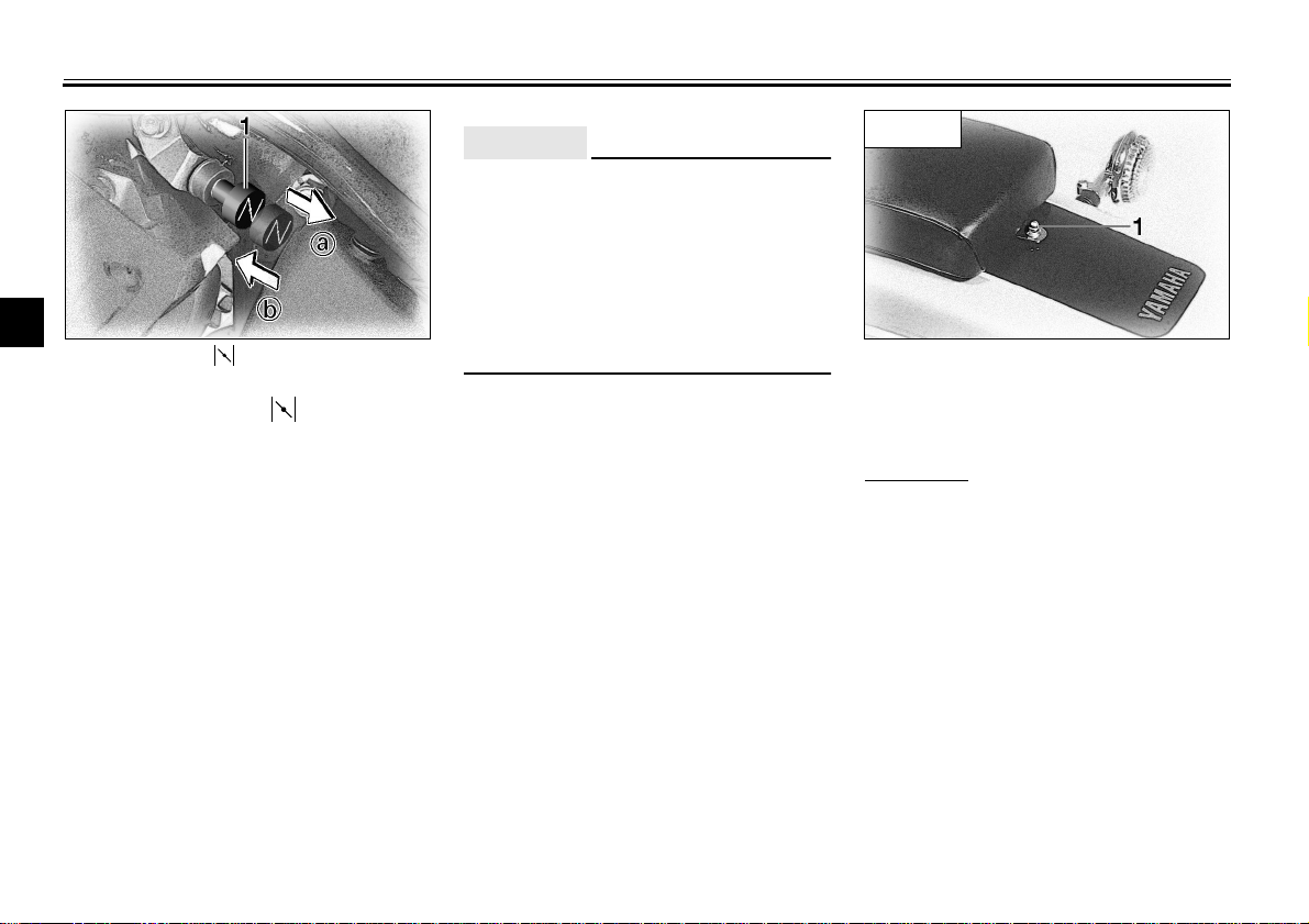
1. Starter (choke) “ ”
4
Starter (choke) “ ”
Starting a cold engine requires a richer
5
air-fuel mixture. A separate starter circuit supplies this mixture.
6
Move in direction
starter (choke).
7
Move in direction
starter (choke).
8
9
a
to turn on the
b
to turn off the
EAU02973
ECA00038
CAUTION:
Do not use the starter (choke) for
more than 3 minutes as the exhaust
pipe may discolor from excessive
heat. Also, longer use of the starter
(choke) will cause afterburning. If
afterburning occurs, turn off the
starter (choke).
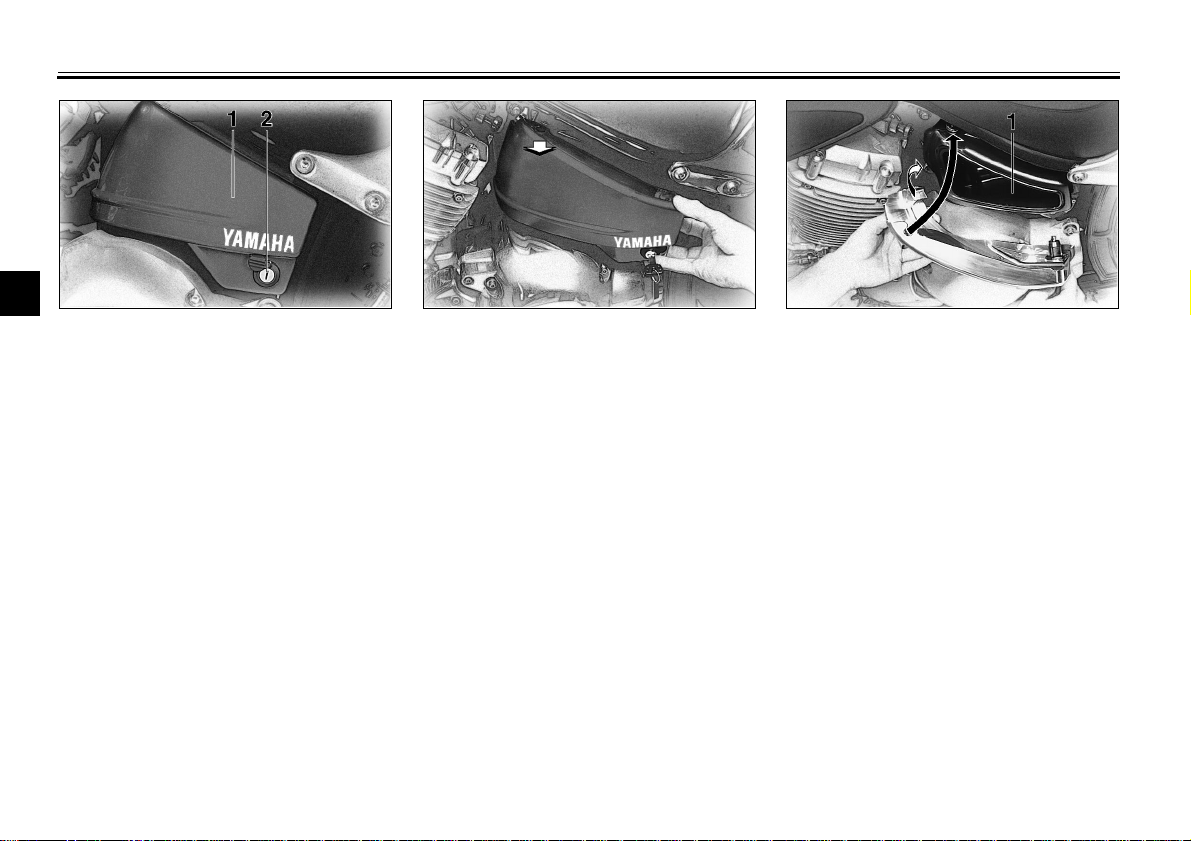
XVS650
1. Nut
EAU01889
Seats (for XVS650)
Passenger seat
To remove
Remove the nut and pull the seat upward.
3-9
INSTRUMENT AND CONTROL FUNCTIONS
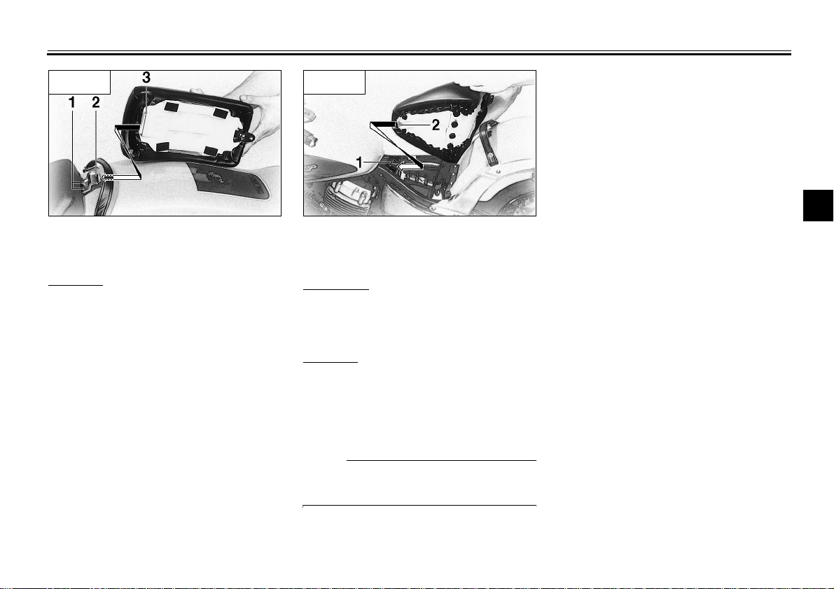
XVS650
1. Bolt ( × 2)
2. Seat holder
3. Projection
To install
Insert the projection on the front of the
seat into the seat holder and install the
nut.
XVS650
1. Seat holder
2. Projection
Rider seat
To remove
1. Remove the passenger seat.
2. Remove the two bolts and pull the
seat upward.
To install
1. Insert the projection on the front of
the seat into the seat holder and
install the bolts.
2. Install the passenger seat.
NOTE:
Make sure that the seats are securely
fitted.
1
2
3
4
5
6
7
8
9
3-10
INSTRUMENT AND CONTROL FUNCTIONS
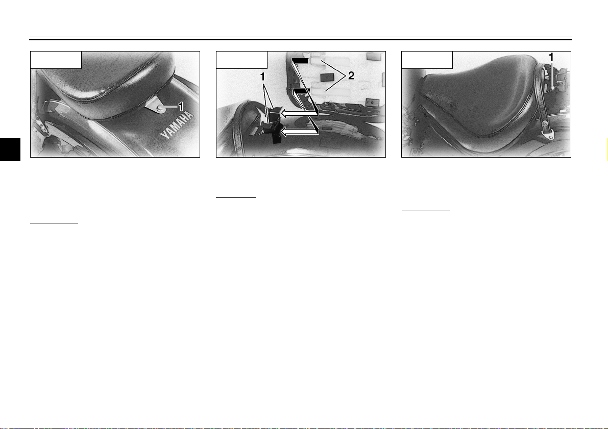
XVS650A
1
2
3
1. Bolt
4
Seats (for XVS650A)
Passenger seat
5
To remove
Remove the bolt and pull the seat up-
6
ward.
7
8
9
EAU01888
XVS650A
1. Seat holder
2. Projection ( × 2)
To install
Insert the projections on the front of the
seat into the holder and install the bolt.
XVS650A
1. Bolt
Rider seat
To remove
1. Remove the passenger seat.
2. Remove the bolt and pull the seat
upward.
3-11
XVS650A
1. Seat holder
2. Projection
To install
1. Insert the projection on the front of
the seat into the holder and install
the bolt.
2. Install the passenger seat.
NOTE:
Make sure that the seats are securely
fitted.
INSTRUMENT AND CONTROL FUNCTIONS
1. Helmet holder
EAU00260
Helmet holder
To open the helmet holder, insert the
key in the lock and turn it as shown. To
lock the helmet holder, replace the
holder in its original position.
EW000030
WARNING
Never ride with a helmet in the helmet holder. The helmet may hit objects, causing loss of control and
possibly an accident.
1
2
3
4
5
6
7
8
9
3-12
INSTRUMENT AND CONTROL FUNCTIONS
1
2
3
1. Compartment cover
2. Lock
4
Storage compartment
5
The storage compartment is located
on the left side of the motorcycle.
6
7
8
9
EAU01869
To open
Slide the lock cover open, insert the
key in the lock and turn it clockwise.
Then, pull the storage compartment
cover out as shown.
1. Storage compartment
To close
Place the storage compartment cover
in its original position as shown. Then,
turn the key counterclockwise and remove it. Close the lock cover.
3-13
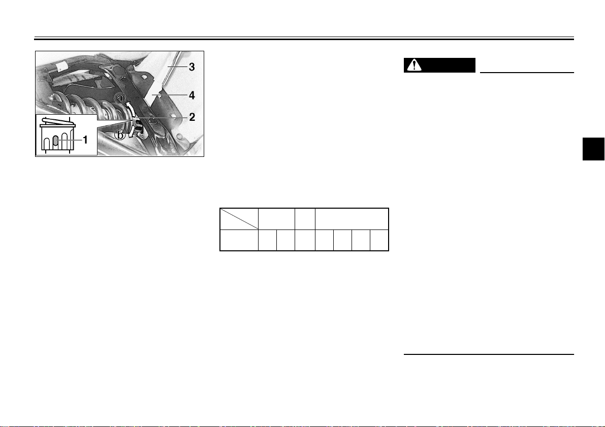
1. Position indicator
2. Adjusting ring
3. Extension bar
4. Special wrench
EAU00299*
Rear shock absorber adjustment
This shock absorber is equipped with a
spring preload adjuster. Adjust spring
preload as follows:
1. Remove the passenger seat and
rider seat. (See page 3-9 for removal procedures.)
INSTRUMENT AND CONTROL FUNCTIONS
2. Use the special wrench and the
extension bar in the owner’s tool
kit to turn the adjusting ring. Turn
the adjusting ring in direction a
to increase spring preload and in
direction b to decrease spring
preload. Make sure that the appropriate notch in the adjusting
ring is aligned with the position indicator on the rear shock absorber.
COPY CI-15ECI-15E
Adjusting
position
1234567
Soft
Stan-
dard
Hard
3. Install the seats.
WARNING
This shock absorber contains highly pressurized nitrogen gas. Read
and understand the following information before handling the shock
absorber. The manufacturer cannot
be held responsible for property
damage or personal injury that may
result from improper handling.
● Do not tamper with or attempt
to open the cylinder assembly.
● Do not subject the shock ab-
sorber to an open flame or other high heat source. This may
cause the unit to explode due
to excessive gas pressure.
● Do not deform or damage the
cylinder in any way. Cylinder
damage will result in poor
damping performance.
● Take your shock absorber to a
Yamaha dealer for any service.
EAU00315
1
2
3
4
5
6
7
8
9
3-14
 Loading...