

Page 1

RX-V2600
AV Receive r
U
OWNER’S MANUAL
Page 2
IMPORTANT SAFETY INSTRUCTIONS
IMPORTANT SAFETY INSTRUCTIONS
CAUTION
RISK OF ELECTRIC SHOCK
DO NOT OPEN
CAUTION: TO REDUCE THE RISK OF
ELECTRIC SHOCK, DO NOT REMOVE
COVER (OR BACK). NO USER-SERVICEABLE
PARTS INSIDE. REFER SERVICING TO
QUALIFIED SERVICE PERSONNEL.
• Explanation of Graphical Symbols
The lightning flash with arrowhead symbol, within an
equilateral triangle, is intended to alert you to the
presence of uninsulated “dangerous voltage” within
the product’s enclosure that may be of sufficient
magnitude to constitute a risk of electric shock to
persons.
The exclamation point within an equilateral triangle
is intended to alert you to the presence of important
operating and maintenance (servicing) instructions in
the literature accompanying the appliance.
1 Read Instructions – All the safety and operating instructions
should be read before the product is operated.
2 Retain Instructions – The safety and operating instructions
should be retained for future reference.
3 Heed Warnings – All warnings on the product and in the
operating instructions should be adhered to.
4 Follow Instructions – All operating and use instructions
should be followed.
5 Cleaning – Unplug this product from the wall outlet before
cleaning. Do not use liquid cleaners or aerosol cleaners.
6 Attachments – Do not use attachments not recommended by
the product manufacturer as they may cause hazards.
7 Water and Moisture – Do not use this product near water –
for example, near a bath tub, wash bowl, kitchen sink, or
laundry tub; in a wet basement; or near a swimming pool;
and the like.
8 Accessories – Do not place this product on an unstable cart,
stand, tripod, bracket, or table. The product may fall,
causing serious injury to a child or adult, and serious
damage to the product. Use only with a cart, stand, tripod,
bracket, or table recommended by the manufacturer, or sold
with the product. Any mounting of the product should
follow the manufacturer’s instructions, and should use a
mounting accessory recommended by the manufacturer.
9 A product and cart combination should be moved with care.
Quick stops, excessive force, and uneven surfaces may
cause the product and cart combination to
overturn.
10 Ventilation – Slots and openings in the cabinet are provided
for ventilation and to ensure reliable operation of the
product and to protect it from overheating, and these
openings must not be blocked or covered. The openings
should never be blocked by placing the product on a bed,
sofa, rug, or other similar surface. This product should not
be placed in a built-in installation such as a bookcase or rack
unless proper ventilation is provided or the manufacturer’s
instructions have been adhered to.
11 Power Sources – This product should be operated only from
the type of power source indicated on the marking label. If
you are not sure of the type of power supply to your home,
consult your product dealer or local power company. For
products intended to operate from battery power, or other
sources, refer to the operating instructions.
12 Grounding or Polarization – This product may be equipped
with a polarized alternating current line plug (a plug having
one blade wider than the other). This plug will fit into the
power outlet only one way. This is a safety feature. If you
are unable to insert the plug fully into the outlet, try
reversing the plug. If the plug should still fail to fit, contact
your electrician to replace your obsolete outlet. Do not
defeat the safety purpose of the polarized plug.
13 Power-Cord Protection – Power-supply cords should be
routed so that they are not likely to be walked on or pinched
by items placed upon or against them, paying particular
attention to cords at plugs, convenience receptacles, and the
point where they exit from the product.
14 Lightning – For added protection for this product during a
lightning storm, or when it is left unattended and unused for
long periods of time, unplug it from the wall outlet and
disconnect the antenna or cable system. This will prevent
damage to the product due to lightning and power-line
surges.
15 Power Lines – An outside antenna system should not be
located in the vicinity of overhead power lines or other
electric light or power circuits, or where it can fall into such
power lines or circuits. When installing an outside antenna
system, extreme care should be taken to keep from touching
such power lines or circuits as contact with them might be
fatal.
16 Overloading – Do not overload wall outlets, extension
cords, or integral convenience receptacles as this can result
in a risk of fire or electric shock.
17 Object and Liquid Entry – Never push objects of any kind
into this product through openings as they may touch
dangerous voltage points or short-out parts that could result
in a fire or electric shock. Never spill liquid of any kind on
the product.
18 Servicing – Do not attempt to service this product yourself
as opening or removing covers may expose you to
dangerous voltage or other hazards. Refer all servicing to
qualified service personnel.
19 Damage Requiring Service – Unplug this product from the
wall outlet and refer servicing to qualified service personnel
under the following conditions:
a) When the power-supply cord or plug is damaged,
b) If liquid has been spilled, or objects have fallen into the
product,
c) If the product has been exposed to rain or water,
i
Page 3
IMPORTANT SAFETY INSTRUCTIONS
d) If the product does not operate normally by following
the operating instructions. Adjust only those controls
that are covered by the operating instructions as an
improper adjustment of other controls may result in
damage and will often require extensive work by a
qualified technician to restore the product to its normal
operation,
e) If the product has been dropped or damaged in any
way, and
f) When the product exhibits a distinct change in
performance - this indicates a need for service.
20 Replacement Parts – When replacement parts are required,
be sure the service technician has used replacement parts
specified by the manufacturer or have the same
characteristics as the original part. Unauthorized
substitutions may result in fire, electric shock, or other
hazards.
21 Safety Check – Upon completion of any service or repairs to
this product, ask the service technician to perform safety
checks to determine that the product is in proper operating
condition.
22 Wall or Ceiling Mounting – The unit should be mounted
to a wall or ceiling only as recommended by the
manufacturer.
23 Heat – The product should be situated away from heat
sources such as radiators, heat registers, stoves, or other
products (including amplifiers) that produce heat.
Note to CATV system installer:
This reminder is provided to call the CATV system
installer’s attention to Article 820-40 of the NEC that
provides guidelines for proper grounding and, in
particular, specifies that the cable ground shall be
connected to the grounding system of the building, as
close to the point of cable entry as practical.
24 Outdoor Antenna Grounding – If an outside antenna or
cable system is connected to the product, be sure the antenna
or cable system is grounded so as to provide some
protection against voltage surges and built-up static charges.
Article 810 of the National Electrical Code, ANSI/NFPA 70,
provides information with regard to proper grounding of the
mast and supporting structure, grounding of the lead-in wire
to an antenna discharge unit, size of grounding conductors,
location of antenna discharge unit, connection to grounding
electrodes, and requirements for the grounding electrode.
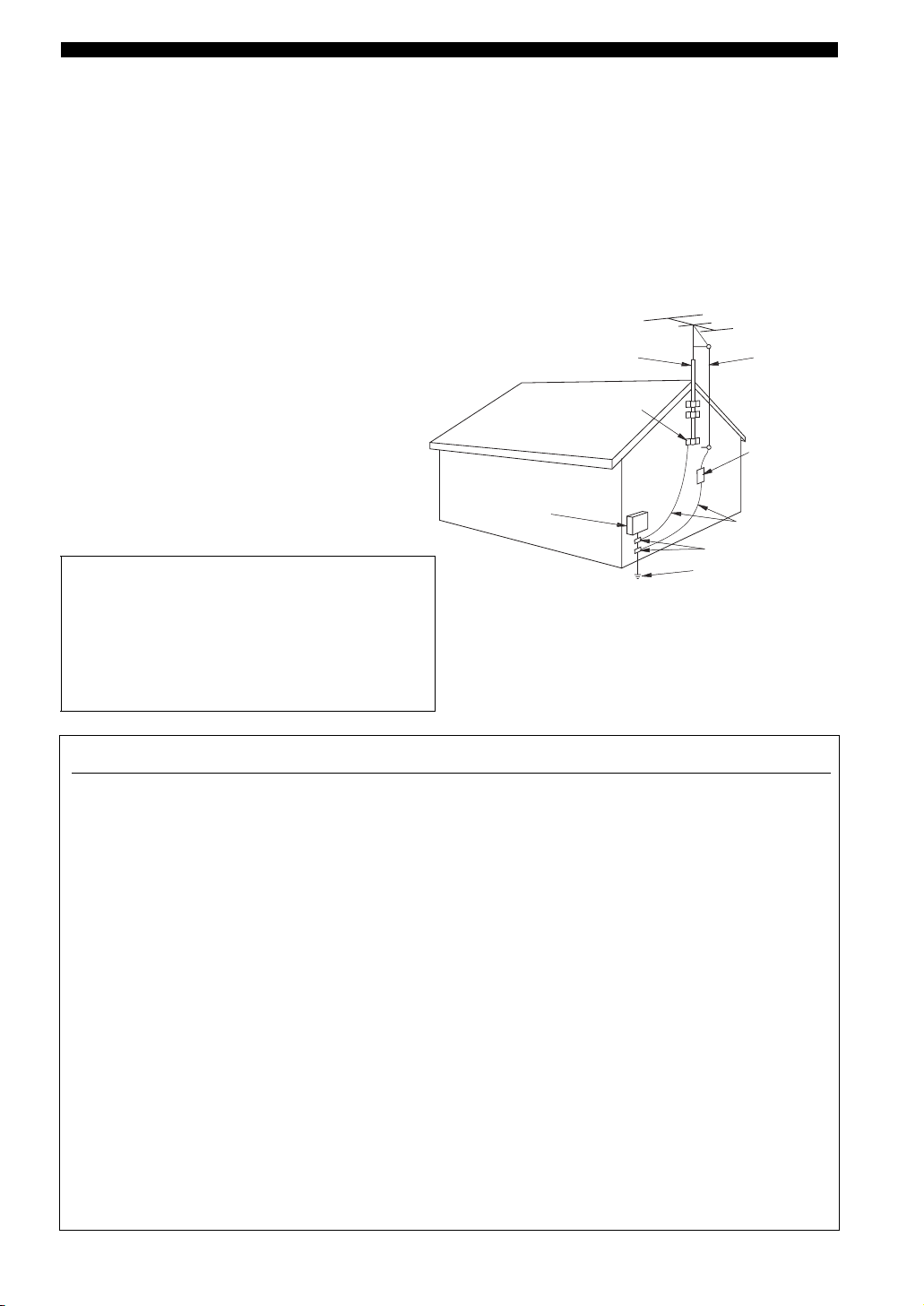
EXAMPLE OF ANTENNA GROUNDING
ANTENNA
LEAD IN
WIRE
ANTENNA
DISCHARGE UNIT
(NEC SECTION 810–20)
GROUNDING CONDUCTORS
(NEC SECTION 810–21)
GROUND CLAMPS
ELECTRIC
SERVICE
EQUIPMENT
NEC – NATIONAL ELECTRICAL CODE
MAST
GROUND
CLAMP
POWER SERVICE GROUNDING
ELECTRODE SYSTEM
(NEC ART 250. PART H)
FCC INFORMATION (for US customers)
1 IMPORTANT NOTICE: DO NOT MODIFY THIS
UNIT!
This product, when installed as indicated in the
instructions contained in this manual, meets FCC
requirements. Modifications not expressly approved by
Yamaha may void your authority, granted by the FCC, to
use the product.
2 IMPORTANT: When connecting this product to
accessories and/or another product use only high quality
shielded cables. Cable/s supplied with this product MUST
be used. Follow all installation instructions. Failure to
follow instructions could void your FCC authorization to
use this product in the USA.
3 NOTE: This product has been tested and found to comply
with the requirements listed in FCC Regulations, Part 15
for Class “B” digital devices. Compliance with these
requirements provides a reasonable level of assurance that
your use of this product in a residential environment will
not result in harmful interference with other electronic
devices.
This equipment generates/uses radio frequencies and, if
not installed and used according to the instructions found
in the users manual, may cause interference harmful to the
operation of other electronic devices.
Compliance with FCC regulations does not guarantee that
interference will not occur in all installations. If this
product is found to be the source of interference, which
can be determined by turning the unit “OFF” and “ON”,
please try to eliminate the problem by using one of the
following measures:
Relocate either this product or the device that is being
affected by the interference.
Utilize power outlets that are on different branch (circuit
breaker or fuse) circuits or install AC line filter/s.
In the case of radio or TV interference, relocate/reorient
the antenna. If the antenna lead-in is 300 ohm ribbon lead,
change the lead-in to coaxial type cable.
If these corrective measures do not produce satisfactory
results, please contact the local retailer authorized to
distribute this type of product. If you can not locate the
appropriate retailer, please contact Yamaha Electronics
Corp., U.S.A. 6660 Orangethorpe Ave, Buena Park, CA
90620.
The above statements apply ONLY to those products
distributed by Yamaha Corporation of America or its
subsidiaries.
ii
Page 4
CAUTION: READ THIS BEFORE OPERATING YOUR UNIT.
CAUTION: READ THIS BEFORE OPERATING YOUR UNIT.
1 To assure the finest performance, please read this manual
carefully. Keep it in a safe place for future reference.
2 Install this sound system in a well ventilated, cool, dry, clean
place – away from direct sunlight, heat sources, vibration,
dust, moisture, and/or cold. Allow ventilation space of at least
30 cm on the top, 20 cm on the left and right, and 20 cm on
the back of this unit.
3 Locate this unit away from other electrical appliances, motors,
or transformers to avoid humming sounds.
4 Do not expose this unit to sudden temperature changes from
cold to hot, and do not locate this unit in an environment with
high humidity (i.e. a room with a humidifier) to prevent
condensation inside this unit, which may cause an electrical
shock, fire, damage to this unit, and/or personal injury.
5 Avoid installing this unit where foreign objects may fall onto
this unit and/or this unit may be exposed to liquid dripping or
splashing. On the top of this unit, do not place:
– Other components, as they may cause damage and/or
discoloration on the surface of this unit.
– Burning objects (i.e. candles), as they may cause fire,
damage to this unit, and/or personal injury.
– Containers with liquid in them, as they may fall and liquid
may cause electrical shock to the user and/or damage to
this unit.
6 Do not cover this unit with a newspaper, tablecloth, curtain,
etc. in order not to obstruct heat radiation. If the temperature
inside this unit rises, it may cause fire, damage to this unit,
and/or personal injury.
7 Do not plug in this unit to a wall outlet until all connections
are complete.
8 Do not operate this unit upside-down. It may overheat,
possibly causing damage.
9 Do not use force on switches, knobs and/or cords.
10 When disconnecting the power cable from the wall outlet,
grasp the plug; do not pull the cable.
11 Do not clean this unit with chemical solvents; this might
damage the finish. Use a clean, dry cloth.
12 Only voltage specified on this unit must be used. Using this
unit with a higher voltage than specified is dangerous and may
cause fire, damage to this unit, and/or personal injury.
YAMAHA will not be held responsible for any damage
resulting from use of this unit with a voltage other than
specified.
13 To prevent damage by lightning, keep the power cord and
outdoor antennas disconnected from a wall outlet or the unit
during a lightning storm.
14 Do not attempt to modify or fix this unit. Contact qualified
YAMAHA service personnel when any service is needed. The
cabinet should never be opened for any reasons.
15 When not planning to use this unit for long periods of time
(i.e. vacation), disconnect the AC power plug from the wall
outlet.
16 Install this unit near the AC outlet and where the AC power
plug can be reached easily.
17 Be sure to read the “TROUBLESHOOTING” section on
common operating errors before concluding that this unit is
faulty.
18 Before moving this unit, press MASTER ON/OFF to release it
outward to the OFF position to turn off this unit, the main
room, Zone 2 and Zone 3 and then disconnect the AC power
plug from the AC wall outlet.
WAR NING
TO REDUCE THE RISK OF FIRE OR ELECTRIC
SHOCK, DO NOT EXPOSE THIS UNIT TO RAIN
OR MOISTURE.
As long as this unit is connected to the AC wall outlet,
it is not disconnected from the AC power source even
if you turn off this unit by MASTER ON/OFF. In this
state, this unit is designed to consume a very small
quantity of power.
FOR CANADIAN CUSTOMERS
To prevent electric shock, match wide blade of plug to
wide slot and fully insert.
This Class B digital apparatus complies with Canadian
ICES-003.
POUR LES CONSOMMATEURS CANADIENS
Pour éviter les chocs électriques, introduire la lame la
plus large de la fiche dans la borne correspondante de
la prise et pousser jusqu’au fond.
Cet appareil numérique de la classe B est conforme à
la norme NMB-003 du Canada.
IMPORTANT
Please record the serial number of this unit in the space
below.
MODEL:
Serial No.:
The serial number is located on the rear of the unit.
Retain this Owner’s Manual in a safe place for future
reference.
We Want You Listening For A Lifetime
YAMAHA and the Electronic Industries Association’s Consumer Electronics Group want you to get the most out of your
equipment by playing it at a safe level. One that lets the sound come through loud and clear without annoying blaring or
distortion – and, most importantly, without affecting your sensitive hearing. Since hearing damage from loud sounds is
often undetectable until it is too late, YAMAHA and the Electronic Industries Association’s Consumer Electronics Group
recommend you to avoid prolonged exposure from excessive volume levels.
iii
Page 5

CONTENTS
INTRODUCTION
FEATURES ............................................................. 2
GETTING STARTED............................................ 3
Supplied accessories .................................................. 3
Installing batteries in the remote controls.................. 4
Handling the remote control ...................................... 5
Opening and closing the front panel door.................. 5
CONTROLS AND FUNCTIONS ......................... 6
Front panel ................................................................. 6
Remote control........................................................... 8
Zone 2/Zone 3 remote control ................................. 10
Front panel display .................................................. 11
Rear panel ................................................................ 13
PREPARATION
CONNECTIONS .................................................. 14
Before connecting speakers ..................................... 14
Connecting speakers ................................................ 15
Using bi-wire and bi-AMP connections .................. 19
Information on cables and jacks
used for connections ............................................ 20
Connecting HDMI components ............................... 23
Connecting video components................................. 24
Connecting audio components................................. 27
Connecting the antennas .......................................... 29
Connecting the power cable..................................... 30
Turning on and off this unit ..................................... 30
Setting the speaker impedance................................. 31
AUTO SETUP....................................................... 32
Introduction.............................................................. 32
Optimizer microphone setup.................................... 32
Using AUTO SETUP .............................................. 33
Confirming the results ............................................. 35
BASIC OPERATION
PLAYBACK.......................................................... 37
Basic operations....................................................... 37
Additional operations............................................... 39
RECORDING ....................................................... 46
FM/AM TUNING ................................................. 47
Automatic tuning ..................................................... 47
Manual tuning .......................................................... 48
Automatic preset tuning........................................... 48
Manual preset tuning ............................................... 50
Selecting preset stations........................................... 51
Exchanging preset stations ...................................... 52
XM® SATELLITE RADIO TUNING ............... 53
What is XM Satellite Radio? ................................... 53
XM Satellite Radio connections .............................. 53
XM Satellite Radio controls and functions.............. 54
Activating XM Satellite Radio ................................ 55
Selecting the XM Satellite Radio mode................... 56
Using XM Satellite Radio search modes ................. 57
Setting XM Satellite Radio preset channels ............ 60
Displaying the XM Satellite Radio
information .......................................................... 62
SOUND FIELD PROGRAMS
EDITING SOUND FIELD PARAMETERS ......63
What is a sound field? ............................................. 63
Changing parameter settings ................................... 63
SOUND FIELD PROGRAM
DESCRIPTIONS...............................................65
For movie/video sources .......................................... 65
For music sources .................................................... 67
SOUND FIELD PARAMETER
DESCRIPTIONS...............................................68
SOUND FIELD PROGRAM
SPEAKER LAYOUTS......................................73
ADVANCED OPERATION
SYSTEM OPTIONS .............................................77
Changing parameter settings ................................... 79
Input Select .............................................................. 80
Manual Setup (Sound) ............................................. 83
Manual Setup (Video) ............................................. 87
Manual Setup (Basic) .............................................. 90
Manual Setup (Option) ............................................ 94
System Memory....................................................... 99
Language ............................................................... 100
ADVANCED SETUP ..........................................101
Using ADVANCED SETUP ................................. 101
REMOTE CONTROL FEATURES .................103
Control area ........................................................... 103
Controlling each component.................................. 104
Setting remote control codes ................................. 105
Using LEARN ....................................................... 107
Using RE-NAME .................................................. 109
Using MACRO ...................................................... 110
Using CLEAR........................................................ 112
ZONE 2/ZONE 3 .................................................115
Connecting the Zone 2 and
Zone 3 components ........................................... 115
Selecting Zone 2 or Zone 3.................................... 116
Controlling Zone 2 and Zone 3.............................. 117
Using the control mode of
Zone 2 and Zone 3 ............................................. 118
HDMI ...................................................................119
What is HDMI? ..................................................... 119
Setting the HDMI parameters................................ 120
Basic HDMI operations ......................................... 120
ADDITIONAL INFORMATION
TROUBLESHOOTING .....................................121
GLOSSARY.........................................................128
Audio information ................................................. 128
Video information.................................................. 131
Sound field program information .......................... 131
Parametric equalizer information .......................... 132
SPECIFICATIONS.............................................133
PREPARATIONINTRODUCTION
OPERATION
BASIC
SOUND FIELD
PROGRAMS
OPERATION
ADVANCED
INFORMATION
ADDITIONAL
1
Page 6

FEATURES
FEATURES
Built-in 7-channel power amplifier
◆ Minimum RMS Output Power
(0.04% THD, 20 Hz to 20 kHz, 8 Ω)
Front: 130 W + 130 W
Center: 130 W
Surround: 130 W + 130 W
Surround Back: 130 W + 130 W
Sound field features
◆ Proprietary YAMAHA technology for the creation of
sound fields
◆ THX Select2
◆ Dolby Digital/Dolby Digital EX decoder
◆ DTS/DTS-ES Matrix 6.1, Discrete 6.1,
DTS Neo:6 decoder, DTS 96/24
◆ Dolby Pro Logic/Dolby Pro Logic x decoder
◆ Virtual CINEMA DSP
◆ SILENT CINEMA
™
HDMI (High-Definition Multimedia Interface)
◆ HDMI interface for standard, enhanced or
high-definition video as well as multi-channel digital
audio
◆ Analog video to HDMI digital video up-conversion
(composite video ↔ S-video ↔ component video →
HDMI digital video) and up-scaling (480i → 480p/
1080i/720p and 480p → 1080i/720p) capabilities for
monitor out
Sophisticated AM/FM tuner
◆ 40-station random access preset tuning
◆ Automatic preset tuning
◆ Preset station shifting capability (preset editing)
XM Satellite Radio (U.S.A. model only)
◆ XM Satellite Radio tuning capability
Other features
◆ YPAO (YAMAHA Parametric Room Acoustic
Optimizer) for automatic speaker setup
◆ 192-kHz/24-bit D/A converter
◆ GUI (graphical user interface) menus that allow you to
optimize this unit to suit your individual audio/video
system
◆ GUI display menu language switching capability
(English, Japanese, French, German and Spanish)
◆ 6 or 8-channel additional input jacks for discrete
multi-channel input
◆ Short message function
◆ PURE DIRECT for pure fidelity sound with analog and
PCM sources
◆ S-video input/output capability
◆ Component video input/output capability
◆ Analog video I/P conversion from 480i to 480p
◆ Optical and coaxial digital audio signal jacks
◆ Sleep timer
◆ Cinema and music night listening mode
◆ Remote control with preset remote control codes and
learning/macro capability
◆ Zone 2/Zone 3 custom installation facility
◆ Zone 2/Zone 3 remote control to control Zone 2 or
Zone 3
◆ Zone 2 OSD (on-screen display) capability
• y indicates a tip for your operation.
• Some operations can be performed by using either the buttons on the main unit or on the remote control. In cases when the button
names differ between the main unit and the remote control, the button name on the remote control is given in parentheses.
• This manual is printed prior to production. Design and specifications are subject to change in part as a result of improvements, etc.
In case of differences between the manual and product, the product has priority.
Manufactured under license from Dolby Laboratories.
“Dolby”, “Surround EX”, and the double-D symbol are
trademarks of Dolby Laboratories.
“DTS”, “DTS-ES”, “Neo:6” and “DTS 96/24” are trademarks of
Digital Theater Systems, Inc.
“HDMI”, the “HDMI” logo and “High-Definition Multimedia
Interface” are trademarks or registered trademarks of HDMI
Licensing LLC.
“SILENT CINEMA” is a trademark of YAMAHA
CORPORATION.
The THX logo is a trademark of THX Ltd. which may be
registered in some jurisdictions. All rights reserved.
© 2005 XM Satellite Radio Inc. All rights reserved. All other
trademarks are the property of their respective owners.
2
Page 7
GETTING STARTED
k
k
k
k
GETTING STARTED
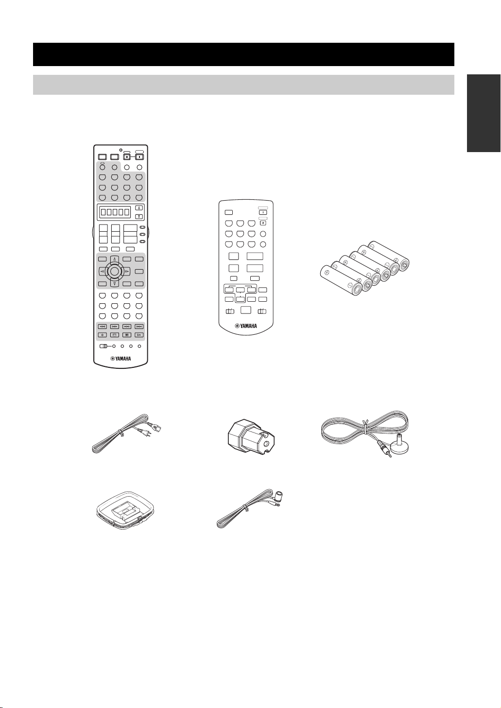
Supplied accessories
Please check that you received all of the following parts.
Remote control
POWER POWER
A
A
PHONO TUNER CD
PHONO TUNER CD
V-AUX
V-AUX
DTV DVR/VCR2VCR 1 DVD
DTV DVR/VCR2VCR 1 DVD
+
TV VOL
–
TV MUTE TV INPUT
GUI TOP
GUI TOP
TITLE
TITLE
BAND
BAND
RETURN
RETURN
XM MEMORY
XM MEMORY
STEREO
THX
5678
1
90
REC
DISC SKIP
POWER
STANDBY
AVTV
XM
XM
SLEEP
AUDIO SEL
MULTI CH IN
MULTI CH IN
CD-R
CD-R
CBL/SAT MD/TAPE
CBL/SAT MD/TAPE
SELECT
AMP
+
+
SOURCE
VOLUME
CH
TV
–
–
MUTE
PRESET/CH
PRESET/CH
EXIT
EXIT
PURE DIRECT
PURE DIRECT
MENU
MENU
SRCH MODE
SRCH MODE
NIGHT
NIGHT
ENTER
ENTER
AUDIO
AUDIO
A-E/CAT.
A-E/CAT.
STRAIGHT
STRAIGHT
DISPLAY
DISPLAY
EFFECT
EFFECT
MUSIC ENTERTAIN MOVIE
3421
STANDARD SELECT EXTD SUR.
2B
A
SPEAKERSMEMORY
ENT.
+10
CLEAR
LEARN
MACROONOFF
RE–NAME
Zone 2/Zone 3
remote control
XM
TUNER1CD2CD-R
DTV4CBL/SAT5MD/TAPE
VCR17DVR/VCR2
8 9
+–+
PRESET
A/B/C/D/E
A-E/CAT.
PRESET/CH
ALL
ID2ID1
NUMBER
3
6
DVD
VOLUME
PRESET
INTRODUCTION
POWER
STANDBY
PHONO
ENT
V-AUX
0
0
–
MUTE
DISPLAY
CAT.
ZONE 3ZONE 2
Batteries (x6)
(AAA, LR03)
Power cabl e
Speaker terminal
Optimizer microphone
wrench
AM loop antenna
Indoor FM antenna
3
Page 8
GETTING STARTED
1
3
2
Installing batteries in the remote controls
Notes
• Change all of the batteries if you notice conditions such as the operation range of the remote control decreases, the indicator does not
flash, or its light or display window become dim.
• Do not use old batteries together with new ones.
• Do not use different types of batteries (such as alkaline and manganese batteries) together. Read the packaging carefully as these
different types of batteries may have the same shape and color.
• We strongly recommend using alkaline batteries.
• If the batteries have leaked, dispose of them immediately. Avoid touching the leaked material or letting it come into contact with
clothing, etc. Clean the battery compartment thoroughly before installing new batteries.
• Do not throw away batteries with general house waste; dispose of them correctly in accordance with your local regulations.
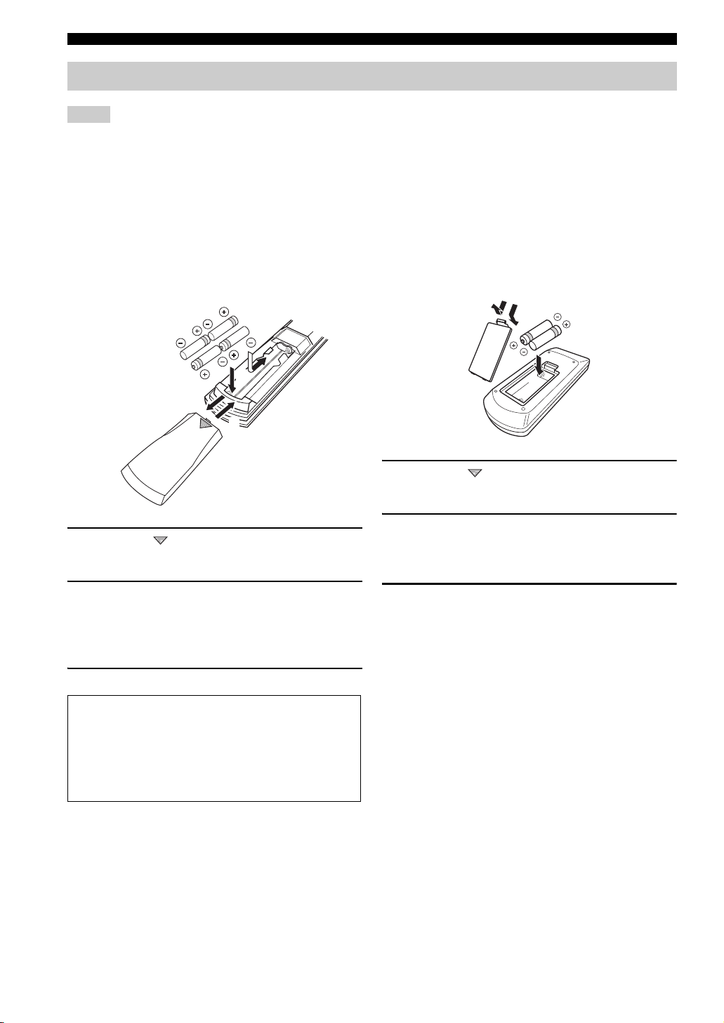
■ Installing batteries
1 Press the part and slide the battery
compartment cover off.
2 Insert four supplied batteries
(AAA, LR03) according to the polarity
markings on the inside of the battery
compartment.
3 Slide the cover back until it snaps into place.
■ Zone 2/Zone 3 remote control
1
3
2
1 Press the part and slide the battery
compartment cover off.
2 Insert two supplied batteries (AAA, LR03)
according to the polarity markings (+ and –)
on the inside of the battery compartment.
3 Slide the cover back until it snaps into place.
If the remote control is without batteries for more than
2 minutes, or if exhausted batteries remain in the
remote control, the contents of the memory may be
cleared. When the memory is cleared, insert new
batteries, set up the remote control code and program
any acquired functions that may have been cleared.
4
Page 9
Handling the remote control
GETTING STARTED
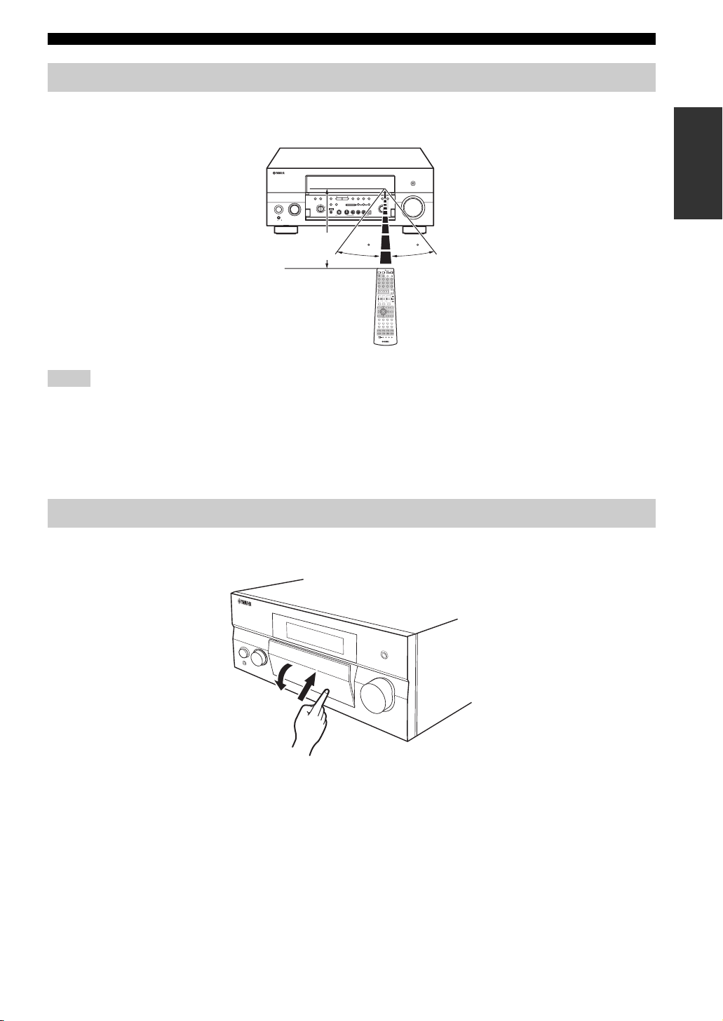
The remote control transmits a directional infrared ray.
Be sure to aim the remote control directly at the remote control sensor on the main unit during operation.
PURE DIRECT
AUDIO
SELECT
INPUTMAIN ZONE
DTV
CBL/SAT
VCR 1
ON/OFF
DVR/
VCR 2
V-AUX
REC OUT/ZONE 2
MASTER
ON OFF
Approximately 6 m (20 ft)
MULTI CH
PRESET/
TUNING
MEMORY
FM/AM
INPUT
PRESET/TUNING/CH
TUNING
MODE
A/B/C/D/E
EDIT
CATEGORY
MAN'L/AUTO FM
SEARCH MODE
DISPLAY
AUTO/MAN'L EFFECT
ZONE ON/OFF
ZONE CONTROL
SPEAKERS
SOURCE/
REMOTE
MD/TAPEDVD
MULTI ZONE
CD-R
A
B
ZONE 2
ZONE 3
CD
YPAO
SILENT CINEMA S VIDEO VIDEO L
AUDIO R OPTICAL
PHONO
TUNER
OPTIMIZER
PHONES
MIC
VIDEO/AUX
STRAIGHT
PROGRAM
POWER POWER
A
PHONO TUNER CD
V-AUX
DTV DVR/VCR2VCR 1 DVD
+
TV VOL
–
TV MUTE TV INPUT
GUI TOP
TITLE
BAND
RETURN
XM MEMORY
STEREO
THX
5678
1
90
REC
DISC SKIP
AVTV
XM
CBL/SAT MD/TAPE
+
CH
–
PRESET/CH
ENTER
MUSIC ENTERTAIN MOVIE
STANDARDSELECT EXTD SUR.
2B
MACROONOFF
VOLUME
TONE
CONTROL
30 30
POWER
STANDBY
SLEEP
AUDIO SEL
MULTI CH IN
CD-R
SELECT
AMP
+
SOURCE
VOLUME
TV
–
MUTE
PURE DIRECT
EXIT
MENU
SRCH MODE
NIGHT
AUDIO
A-E/CAT.
STRAIGHT
DISPLAY
EFFECT
3421
A
SPEAKERSMEMORY
ENT.
+10
CLEAR
LEARN
RE–NAME
Notes
• Do not spill water or other liquids on the remote control.
• Do not drop the remote control.
• Do not leave or store the remote control in the following types of conditions:
– places of high humidity, such as near a bath
– places of high temperatures, such as near a heater or stove
– extremely low temperatures
– dusty places
INTRODUCTION
Opening and closing the front panel door
When you want to use the controls behind the front panel door, open the door by gently pressing on the lower part of the
panel. Keep the door closed when not using these controls.
To open, press gently on the lower part of the panel.
5
Page 10
CONTROLS AND FUNCTIONS
GJ MNLKIH
CONTROLS AND FUNCTIONS
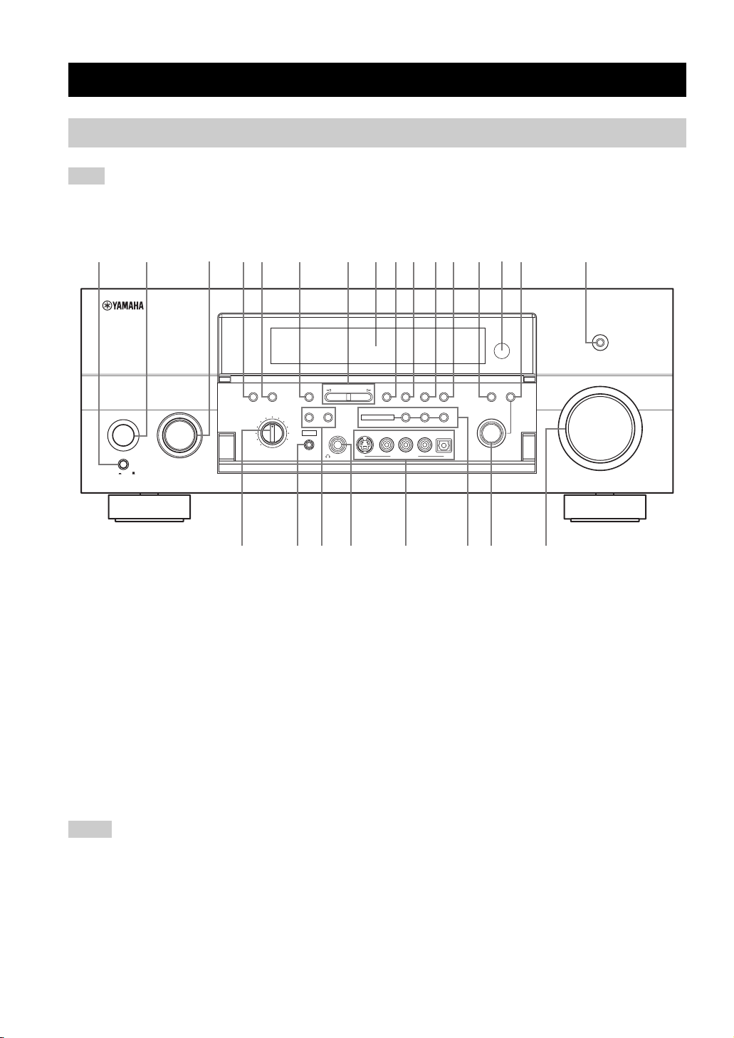
Front panel
Note
The XM Satellite Radio controls (SEARCH MODE, CATEGORY, PRESET/TUNING/CH l / h, MEMORY and DISPLAY) are only
applicable to the U.S.A. model and are operational only when XM is selected as the input source. For details, see “Front panel
functions” on page 54.
12 4567890ABCE F
ON/OFF
MASTER
ON OFF
1 MASTER ON/OFF
Press inward to the ON position.
• Turns on this unit.
• Turns on the main room.
• Sets Zone 2 and Zone 3 to the standby mode.
Press again to release it outward to the OFF position.
• Turns off this unit.
• Turns off the main room, Zone 2 and Zone 3.
See page 30 for details.
2 MAIN ZONE ON/OFF
Turns on this unit only or sets it to the standby mode.
y
In the standby mode, this unit consumes a small quantity of
power.
Notes
• When you turn on this unit, there will be a 6 to 7 second delay
before this unit can reproduce sound.
• This button is operational only when MASTER ON/OFF is
pressed inward to the ON position.
3 INPUT selector
Selects the desired input source.
3
MULTI CH
AUDIO
INPUT
SELECT
INPUTMAIN ZONE
CBL/SAT
VCR 1
DVR/
VCR 2
DTV
V-AUX
REC OUT/ZONE 2
SOURCE/
REMOTE
MD/TAPEDVD
CD-R
CD
PHONO
TUNER
PRESET/TUNING/CH
A/B/C/D/E
CATEGORY
SPEAKERS
A
B
YPAO
SILENT CINEMA S VIDEO VIDEO L
OPTIMIZER
MIC
PHONES
EDIT
MULTI ZONE
PRESET/
TUNING
SEARCH MODE
FM/AM
DISPLAY
ZONE 2
VIDEO/AUX
MEMORY
MAN'L/AUTO FM
ZONE ON/OFF
ZONE 3
AUDIO R OPTICAL
TUNING
MODE
AUTO/MAN'L EFFECT
ZONE CONTROL
4 AUDIO SELECT
Toggles the priority for the type of audio input jack
between AUTO, HDMI, COAX/OPT and ANALOG when
one component is connected to two or more input jacks on
the rear panel (see page 44).
5 MULTI CH INPUT
Selects the input source connected to the MULTI CH
INPUT jacks. When selected, the MULTI CH INPUT
source takes priority over the input source selected with
the INPUT selector (or the input selector buttons on the
remote control).
6 A/B/C/D/E
Selects one of the 5 preset station groups (A to E) when
TUNER is selected as the input source (see page 51).
7 PRESET/TUNING/CH l / h
Selects the preset station number (1 to 8) when TUNER is
selected as the input source and the colon (:) is displayed
next to the band indication in the front panel display.
Selects the tuning frequency when TUNER is selected as
the input source and the colon (:) is not displayed in the
front panel display.
See pages 47 to 52 for details.
STRAIGHT
PROGRAM
D
TONE
CONTROL
PURE DIRECT
VOLUME
(U.S.A. model)
6
Page 11

CONTROLS AND FUNCTIONS
8 Front panel display
Shows information about the operational status of this
unit.
9 PRESET/TUNING (EDIT)
Switches the function of PRESET/TUNING/CH l / h
between selecting preset station numbers and tuning when
TUNER is selected as the input source (see pages 47 to
52).
0 FM/AM
Switches the reception band (FM or AM) when TUNER is
selected as the input source (see page 47).
Note
The frequency of the previously received station is automatically
recalled.
A MEMORY (MAN’L/AUTO FM)
Stores a station in the memory when TUNER is selected
as the input source. Hold down for more than 3 seconds to
start automatic preset tuning (see page 48).
B TUNING MODE (AUTO/MAN’L), DISPLAY
Switches the tuning mode between automatic (the AUTO
indicator is turned on) and manual (the AUTO indicator is
turned off) when TUNER is selected as the input source.
C STRAIGHT (EFFECT)
Turns the sound field programs on or off. When
STRAIGHT is selected, 2-channel or multi-channel input
signals are output directly from the respective speakers
without effect processing.
D Remote control sensor
Receives infrared signals from the remote control.
E TONE CONTROL
Use to adjust the balance of bass and treble for the front
left and right and center channels (see page 39).
F PURE DIRECT
Turns on or off the PURE DIRECT mode (see page 42).
Note
The indicator around the button lights up when the unit is in the
PURE DIRECT mode.
G REC OUT/ZONE 2
Selects the input source you want to direct to the audio/
video recorder and Zone 2 outputs independently of the
input source you are listening to or watching in the main
room. When set to the SOURCE/REMOTE position, the
input source is directed to all outputs.
Note
The Zone 2 output is always identical with the input source you
record.
H OPTIMIZER MIC jack
Use to connect the supplied optimizer microphone to run
AUTO SETUP (see page 32).
I SPEAKERS A/B
Turn on or off the set of front speakers connected to the
SPEAKERS A and/or B terminals on the rear panel each
time the corresponding button is pressed.
J PHONES (SILENT CINEMA) jack
Outputs audio signals for private listening with
headphones.
Notes
• When you connect headphones, no signals are output at the
PRE OUT jacks or to the speakers.
• All Dolby Digital and DTS audio signals are mixed down to 2channel stereo (front left and right channels).
K VIDEO AUX jacks
Input audio and video signals from an external source such
as a game console. To reproduce source signals at these
jacks, select V-AUX as the input source.
L MULTI ZONE buttons
ZONE 2 ON/OFF
Turns on Zone 2 only or sets it to the standby mode.
See page 30 for details.
Note
This button is operational only when MASTER ON/OFF is
pressed inward to the ON position.
ZONE 3 ON/OFF
Turns on Zone 3 only or sets it to the standby mode.
See page 30 for details.
Note
This button is operational only when MASTER ON/OFF is
pressed inward to the ON position.
ZONE CONTROL
Switches the zone you want to control between the
main unit, Zone 2 and Zone 3 (see page 117).
After you press ZONE CONTROL, the indicator for
the currently selected zone flashes in the front panel
display for approximately 5 seconds. While the
indicator is flashing, perform the desired operation.
M PROGRAM selector
Use to select sound field programs or adjust the balance of
bass and treble in conjunction with TONE CONTROL.
N VOLUME
Controls the volume level of all audio channels.
Note
This does not affect the OUT (REC) level.
INTRODUCTION
7
Page 12
CONTROLS AND FUNCTIONS
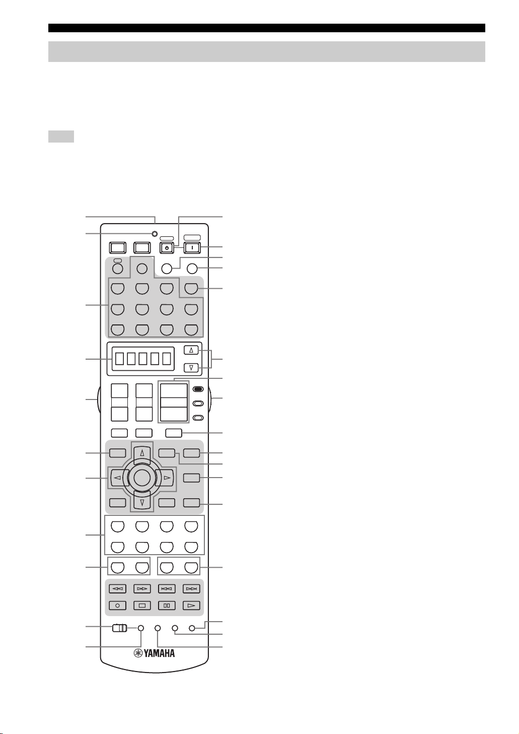
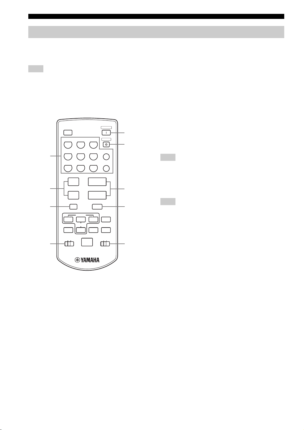
Remote control
This section describes the function of each control on the
remote control used to control this unit. Set AMP/
SOURCE/TV to AMP to operate this unit. To operate
other components, see “REMOTE CONTROL
FEATURES” on page 103.
Note
The XM Satellite Radio controls (XM, XM MEMORY, SRCH
MODE, DISPLAY, cursor buttons k / n / l / h, numeric
buttons and ENT.) are only applicable to the U.S.A. model and
are operational only when XM is selected as the input source. For
details, see “Remote control functions” on page 54.
1
2
POWER POWER
AVTV
XM
A
STANDBY
AUDIO SEL
POWER
SLEEP
B
C
D
E
PHONO TUNER CD
MULTI CH IN
F
3
4
5
6
7
8
9
0
A
V-AUX
CBL/SAT MD/TAPE
DTV DVR/VCR2VCR 1 DVD
+
+
CH
TV VOL
–
–
TV MUTE TV INPUT
PRESET/CH
GUI TOP
TITLE
BAND
ENTER
RETURN
XM MEMORY
STEREO
MUSIC ENTERTAIN MOVIE
THX
STANDARD SELECT EXTD SUR.
5678
1
2B
90
REC
DISC SKIP
LEARN
MACROONOFF
VOLUME
EXIT
MENU
SRCH MODE
A-E/CAT.
DISPLAY
3421
A
+10
+
–
MUTE
SPEAKERSMEMORY
CLEAR
CD-R
SELECT
AMP
SOURCE
TV
PURE DIRECT
NIGHT
AUDIO
STRAIGHT
EFFECT
ENT.
RE–NAME
G
H
I
J
K
L
M
N
O
P
Q
R
1 Infrared window
Outputs infrared control signals. Aim this window at the
component you want to operate.
2 Transmission indicator
Flashes while the remote control is sending infrared
signals.
3 Input selector buttons
Select the input source and change the control area.
Set AMP/SOURCE/TV to SOURCE and then press
TUNER to select TUNER as the input source.
Set AMP/SOURCE/TV to SOURCE and then press XM
to select XM as the input source.
4 Display window
Shows the name of the selected input source that you can
control.
5 Light button
Press to light up the remote control buttons and the display
window.
6 GUI TOP, BAND
Displays the top screen in the graphical user interface
(GUI) menu on your video monitor when AMP/SOURCE/
TV is set to AMP.
Switches the reception band between FM and AM when
AMP/SOURCE/TV is set to SOURCE and TUNER is
selected as the input source.
7 Cursor buttons k / n / l / h, ENTER
Selects and adjusts the DSP program parameters or GUI
menu items when AMP/SOURCE/TV is set to AMP.
Press l / h to select a preset station group (A to E) and
k / n to select a preset station number (1 to 8) when
AMP/SOURCE/TV is set to SOURCE and TUNER is
selected as the input source.
8 Sound field program / numeric buttons
Select sound field programs when AMP/SOURCE/TV is
set to AMP.
Use SELECT to play back 2-channel sources in the multichannel format (see page 41).
Use EXTD SUR. to switch between 5.1 and 6.1/7.1
channel playback of multi-channel software (see page 40).
Use numbers 1 to 8 to select preset stations when AMP/
SOURCE/TV is set to SOURCE and TUNER is selected
as the input source.
9 MEMORY 1/2
Use to recall favorite sound field programs, YPAO settings
or additional preset stations (see page 99).
0 MACRO ON/OFF
Turns on or off the macro function (see page 111).
(U.S.A. model)
8
Page 13

CONTROLS AND FUNCTIONS
A MACRO
Programs a series of operations to be controlled with a
single button (see page 110).
B STANDBY
Sets this unit, Zone 2 and Zone 3 to the standby mode (see
page 30).
Note
This button is operational only when MASTER ON/OFF on the
front panel is pressed inward to the ON position.
C POWER
Turns on this unit, Zone 2 and Zone 3 (see page 30).
Note
This button is operational only when MASTER ON/OFF on the
front panel is pressed inward to the ON position.
D AUDIO SEL
Toggles the priority for the type of audio input jack
between AUTO, HDMI, COAX/OPT and ANALOG when
one component is connected to two or more input jacks on
the rear panel (see page 44).
E SLEEP
Sets the sleep timer.
F MULTI CH IN
Selects MULTI CH INPUT when using an external
decoder, etc.
G SELECT k / n
Selects another input source that you can control
independently of the input source selected with the input
selector buttons.
H VOLUME +/–
Increases or decreases the volume level.
I AMP/SOURCE/TV
Selects the component you want to control with the
remote control.
AMP
Set to this position to operate this unit.
SOURCE
Set to this position to operate the component selected with
an input selector button.
TV
Set to this position to operate the television assigned to
either DTV or PHONO.
Note
If televisions are assigned to both DTV and PHONO, the one
assigned to DTV takes priority and gets operated when AMP/
SOURCE/TV is set to TV.
y
To set the remote control codes for other components, see
page 105.
J MUTE
Mutes the sound. Press again to restore the audio output to
the previous volume level.
K PURE DIRECT
Turns on or off the PURE DIRECT mode (see page 42).
L EXIT
Exits the GUI mode.
M NIGHT
Turns on or off the night listening modes (see page 42).
N STRAIGHT (EFFECT)
Switches the sound field programs off or on. When
STRAIGHT is selected, 2-channel or multi-channel input
signals are output directly from their respective speakers
without effect processing.
O SPEAKERS A/B
Turns on or off the set of front speakers connected to the
SPEAKERS A and/or B terminals on the rear panel each
time the corresponding button is pressed.
P RE-NAME
Changes the name of the input source in the display
window (see page 109).
Q CLEAR
Clears remote control codes or functions acquired from
the learn, macro and rename features (see page 112).
R LEARN
Programs remote control codes or functions from other
remote controls (see page 107).
INTRODUCTION
9
Page 14
CONTROLS AND FUNCTIONS
k
k
k
k
Zone 2/Zone 3 remote control
This section describes the function of each control on the
Zone 2/Zone 3 remote control used to control Zone 2 or
Zone 3.
Note
The XM Satellite Radio controls (XM, DISPLAY, PRESET,
ALL, CAT., numeric buttons, NUMBER, cursor buttons
k / n / l / h and ENT) are only applicable to the U.S.A. model
and are operational only when XM is selected as the input source.
For details, see “Zone 2/Zone 3 remote control functions” on
page 55.
XM
POWER
5
TUNER1CD2CD-R
DTV4CBL/SAT5MD/TAPE
1
VCR17DVR/VCR2
8 9
+
2
PRESET
–
3 8
A/B/C/D/E
A-E/CAT.
PRESET/CH
ALL
ID2ID1
4
NUMBER
(U.S.A. model)
3
6
DVD
+
VOLUME
–
MUTE
PRESET
STANDBY
PHONO
ENT
V-AU X
0
0
DISPLAY
CAT.
ZONE 3ZONE 2
6
7
9
1 Input selector buttons
Select the desired input source of Zone 2 or Zone 3 and
change the control area.
2 PRESET +/–
Selects the preset station number (1 to 8) when TUNER is
selected as the input source or Zone 2 or Zone 3.
3 A/B/C/D/E
Selects the preset station group (A to E) when TUNER is
selected as the input source or Zone 2 or Zone 3.
4 ID1/ID2 switch
Switches the remote control ID between ID1 and ID2
(see page 106).
5 POWER
Turns on Zone 2 or Zone 3.
Note
This button is operational only when MASTER ON/OFF on the
front panel is pressed inward to the ON position.
6 STANDBY
Sets Zone 2 or Zone 3 to the standby mode.
Note
This button is operational only when MASTER ON/OFF on the
front panel is pressed inward to the ON position.
7 VOLUME +/–
Increases or decreases the volume level or Zone 2 or
Zone 3.
8 MUTE
Mutes the sound of Zone 2 or Zone 3.
Press again to restore the audio output to the previous
volume level.
9 ZONE 2/ZONE 3 switch
Switches between the operation mode of Zone 2 and that
of Zone 3.
10
Page 15
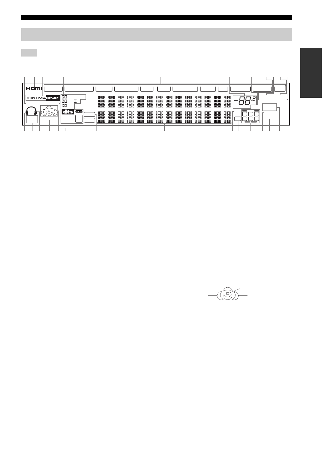
Front panel display
CS
CONTROLS AND FUNCTIONS
Note
The XM indicator is only applicable to the U.S.A. model.
123 4 5 6 7 890A
V-A UX
DIGITAL
YPAO
SP
A B
SILENT
CINEMA
HiFi DSP
VIRTUAL
PL x
EX
DISCRETE
MATRIX
96
24
1 YPAO indicator
Lights up when the AUTO SETUP procedure is in
progress and when the AUTO SETUP speaker settings are
used without any modifications.
2 HDMI indicator
Lights up when HDMI components are assigned to the
HDMI IN 1 and HDMI IN 2 jacks and they are recognized
by this unit.
Turns off when no HDMI component is assigned to the
either HDMI IN 1 or HDMI IN 2 jack or when no HDMI
component is recognized by this unit although they are
assigned to the HDMI IN jacks.
See page 119 for details.
CS
DSD
PCM
I
VCR 1
DTV DVD CD-R CD
MD/TAPECBL/SATDVR/VCR 2
A MEMORY indicator
Flashes to indicate that a station can be stored.
B Headphones indicator
Lights up when headphones are connected.
C SILENT CINEMA indicator
Lights up when headphones are connected and a sound
field program is selected (see page 39).
D SP A B indicators
Light up according to the set of front speakers selected.
Both indicators light up when both sets of front speakers
are selected or when bi-wiring.
VOLUME
96/24
LL C R
LFE
SL SB SR
dB
MUTE
TUNERPHONO
STEREO
AUTO
ZONE2
ZONE3
NIGHT
SLEEP
XM
TUNED
MEMORY
PONMLKJHGFEDCB
E VIRTUAL indicator
3 CINEMA DSP indicator
Lights up when you select a CINEMA DSP sound field
program.
Lights up when Virtual CINEMA DSP is active
(see page 44).
F Sound field indicators
4 Decoder indicators
When any of the decoders of this unit operate, the
respective indicator lights up.
5 Input source indicators
Light up when the corresponding input source is selected.
6 VOLUME level indicator
Indicates the volume level.
7 MUTE indicator
Flashes while the MUTE function is on.
8 AUTO indicator
Lights up when this unit is in the automatic tuning mode.
9 STEREO indicator
Lights up when this unit is receiving a stereo signal for an
FM stereo broadcast while the AUTO indicator is lit.
0 TUNED indicator
Lights up when this unit is tuned into a station.
Light up to indicate the active DSP sound fields.
Presence DSP sound field
Listening position
Left surround
DSP sound field
Surround/surround back DSP sound field
Right surround
DSP sound field
G HiFi DSP indicator
Lights up when you select a HiFi DSP sound field
program.
H PCM indicator
Lights up when this unit is reproducing PCM (pulse code
modulation) digital audio signals.
I DSD indicator
Lights up when this unit is reproducing DSD (direct
stream digital) digital audio signals.
J Multi-information display
Shows the name of the current sound field program and
other information when adjusting or changing settings.
INTRODUCTION
11
Page 16

CONTROLS AND FUNCTIONS
K 96/24 indicator
Lights up when a DTS 96/24 signal is input to this unit.
L LFE indicator
Lights up when the input signal contains an LFE signal.
M Input channel and speaker indicators
Input channel indicators
Indicate the channel components of the current digital
input signal.
LL C R
SL SB SR
Presence and surround back speaker
indicators
Light up according to the number of presence and
surround back speakers set for Presence (see page 92)
and Surround Back (see page 91) in Manual Setup
when Test Tone in Manual Setup is set to On (see
page 90).
y
You can make settings for the presence and surround back
speakers automatically by running Auto Setup (see page 32)
or manually by adjusting settings for Presence (see page 92)
and Surround Back (see page 91) in Manual Setup.
N NIGHT indicator
Lights up when you select a night listening mode.
O SLEEP indicator
Lights up while the sleep timer is on.
P ZONE 2/ZONE 3 indicators
Light up when Zone 2 or Zone 3 is turned on.
12
Page 17
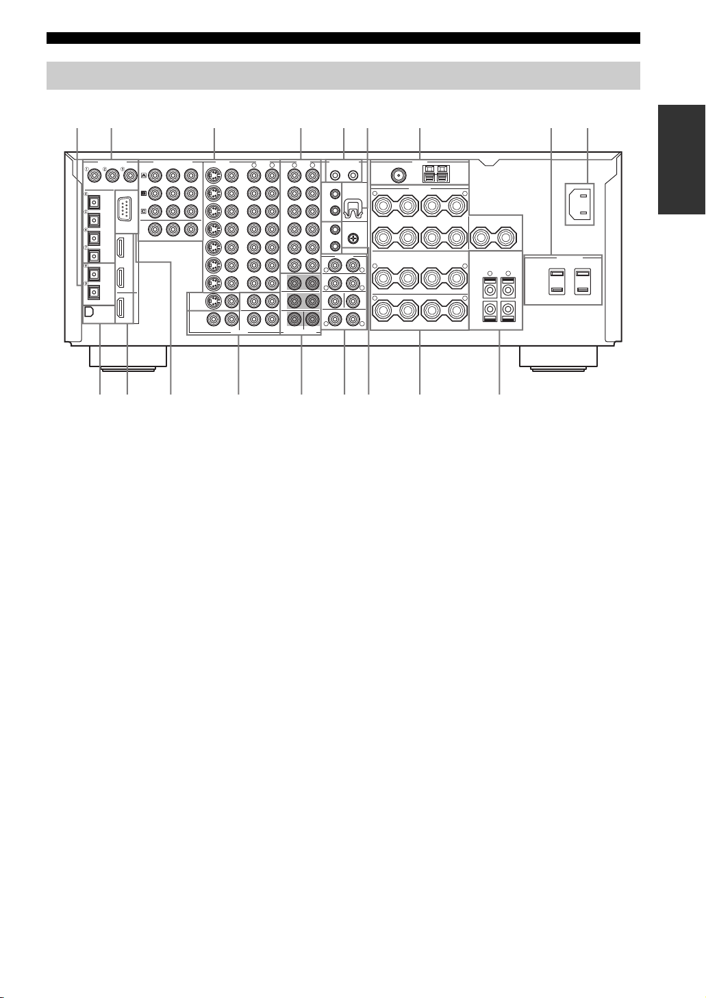
Rear panel
CONTROLS AND FUNCTIONS
12 3 4 56 7 8 9
DIGITAL INPUT
CD DVD
CD
DVD
DTV
CBL/SAT
MD/TAPE
CD-R
DIGITAL OUTPUT
OPTICAL
RS-232C
HDMIXM
COAXIAL
DVR/
VCR 2
IN 1
IN 2
OUT
DVD
DTV
CBL/
SAT
COMPONENT VIDEO
PBY
MONITOR OUT
PR
MONITOR
ZONE 2
VIDEO
S VIDEO
OUT
AUDIOVIDEO
VIDEO
R
L
(PLAY)
IN
MD/TAPE
OUT
(REC)
(PLAY)
IN
CD-R
OUT
(REC)
CD
PHONO
FRONT(6CH)/SB(8CH)
SURROUND
2
3
MULTI CH INPUT
DVR/VCR 2
OUTPUT
DVD
DTV
CBL/
SAT
IN
VCR 1
OUT
IN
OUT
ZONE
ZONE
R
AUDIO
L
CENTERSUBWOOFER
CONTROL OUT
+12V 15mA MAX.
21
REMOTE
WRENCH
HOLDER
IN
1
OUT
GND
IN
2
OUT
PRE OUT
FRONT
R
SURROUND
R
SUBWOOFER
R
SURROUND BACK/PRESENCE
CENTER
L
L
SINGLE
(SB)
L
TUNER
FM ANT
75Ω
UNBAL.
SPEAKERS
+
–
R
FRONT
+
–
SURROUND/ZONE 2(3)
+
R
+
–
R
SURROUND BACK
AM ANT
GND
+
–
A
B
L
CENTER
+
–
++––
+
–
SINGLE
–
SPEAKER IMPEDANCE
L
L
–
PRESENCE/ZONE 2(3)
+
100W MAX.TOTAL
R
SWITCHED
L
(U.S.A. model)
HGFEDCBA0
1 DIGITAL OUTPUT jacks
See pages 24, 25 and 27 for connection information.
2 DIGITAL INPUT jacks
See pages 24, 25 and 27 for details.
3 Video component jacks
See pages 24 and 25 for connection information.
4 Audio component jacks
See pages 24, 25 and 27 for connection information.
5 CONTROL OUT jacks
These are control expansion terminals for factory use only.
6 WRENCH HOLDER
Use to hook the supplied speaker terminal wrench when
not in use (see page 16).
7 Antenna terminals
See page 29 for connection information.
8 AC OUTLETS
Use to supply power to your other A/V components
(see page 30).
9 AC IN
0 XM jack (U.S.A. model only)
See page 53 for connection information.
A HDMI IN/OUT connectors
See page 119 for connection information.
B RS-232C terminal
This is a control expansion terminal for factory use only.
Consult you dealer for details.
C ZONE 2/ZONE 3 OUTPUT jacks
See page 115 for details.
D MULTI CH INPUT jacks
See page 26 for connection information.
E PRE OUT jacks
See page 28 for connection information.
F REMOTE 1/2 IN/OUT jacks
See page 115 for details.
G Speaker terminals
See page 15 for connection information.
H PRESENCE/ZONE 2(3) speaker terminals
See page 17 for connection information.
Use this inlet to plug in the supplied power cable
(see page 30).
AC OUTLETS
INTRODUCTION
AC IN
13
Page 18
CONNECTIONS
CONNECTIONS
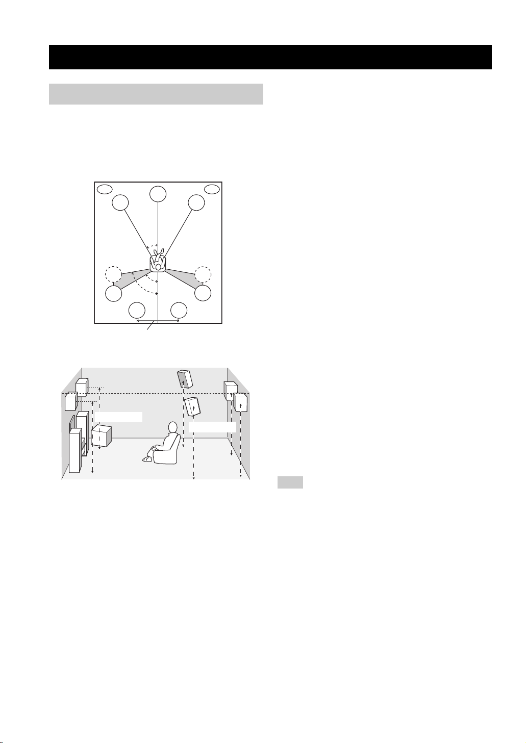
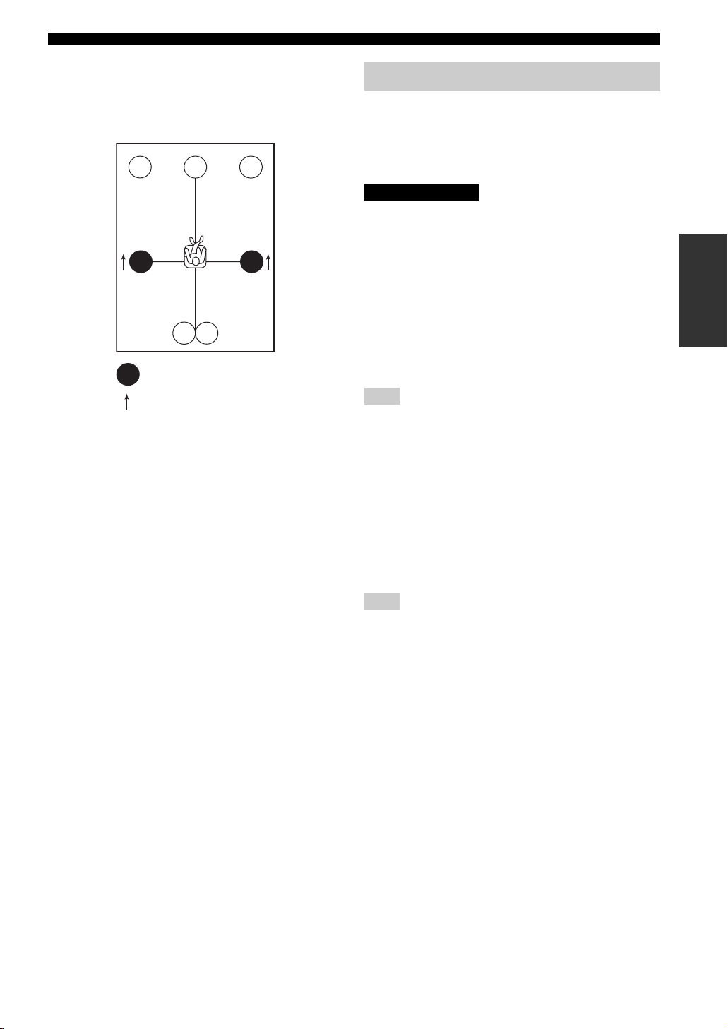
Before connecting speakers
The speaker layout below shows the standard ITU-R*
speaker setting. You can use it to enjoy CINEMA DSP,
multi-channel audio sources and THX.
*
ITU-R is the radio communication sector of the ITU
(International Telecommunication Union).
PL
FL
SL
SL
More than 30 cm (12 in)
1.8 m (6 ft)
80˚
SBL
C
30˚
60˚
SBR
Front speakers (FR and FL)
The front speakers are used for the main source sound plus
effect sounds. Place these speakers an equal distance from
the ideal listening position. The distance of each speaker
from each side of the video monitor should be the same.
Center speaker (C)
The center speaker is for the center channel sounds
(dialog, vocals, etc.). If for some reason it is not practical
to use a center speaker, you can do without it. Best results,
however, are obtained with the full system. Align the front
face of the center speaker with the front face of your video
monitor. Place the speaker centrally between the front
speakers and as close to the monitor as possible, such as
directly over or under it.
PR
FR
SR
SR
1.8 m (6 ft)
Surround speakers (SR and SL)
The surround speakers are used for effect and surround
sounds. Place these speakers behind your listening
position, facing slightly inwards, about 1.8 m (6 ft) above
the floor.
Surround back speakers (SBR and SBL)
The surround back speakers supplement the surround
speakers and provide for more realistic front-to-back
transitions. Place these speakers directly behind the
listening position and at the same height as the surround
speakers. They should be positioned at least 30 cm (12 in)
apart. Ideally, they should be positioned at the same width
as the front speakers.
Subwoofer
The use of a subwoofer, such as the YAMAHA Active
Servo Processing Subwoofer System, is effective not only
for reinforcing bass frequencies from any or all channels,
but also for high fidelity reproduction of the LFE (lowfrequency effect) channel included in Dolby Digital and
DTS software. The position of the subwoofer is not so
critical, because low bass sounds are not highly
directional. But it is better to place the subwoofer near the
front speakers. Turn it slightly toward the center of the
room to reduce wall reflections.
Presence speakers (PR and PL)
Presence speakers supplement the sound from the front
speakers with extra ambient effects produced by CINEMA
DSP (see page 65). These effects include sounds that
filmmakers intend to locate a little farther back behind the
screen in order to create more theater-like ambience. Place
these speakers at the front of the room about 0.5 – 1 m
(1 – 3 ft) outside the front speakers, facing slightly
inwards, and about 1.8 m (6 ft) above the floor.
Note
Surround back and presence speakers do not output sound
simultaneously. You can set to prioritize either set of speakers
using the PR/SB Priority parameter in Manual Setup (see
page 86).
14
Page 19
■ Di-pole speaker layout
Either di-pole or direct radiating speaker types can be used
for THX surround. If you choose di-pole speakers, please
place the surround and surround back speakers according
to the speaker layout below.
FL
SL
: Di-pole speaker
: Direction of the di-pole speaker phase
SBL
C
SBR
FR
SR
CONNECTIONS
Connecting speakers
Be sure to connect the left channel (L), right channel (R),
“+” (red) and “–” (black) properly. If the connections are
faulty, no sound will be heard from the speakers, and if the
polarity of the speaker connections is incorrect, the sound
will be unnatural and lack bass.
CAUTION
• If you will use 6 ohm speakers, be sure to set this unit’s speaker
impedance setting to 6 ohms before using (see page 31). If you
will use 8 ohm speakers, use this unit’s initial setting for
speaker impedance.
• Before connecting the speakers, make sure that this unit is
disconnected from the power source.
• Do not let the bare speaker wires touch each other or do not let
them touch any metal part of this unit. This could damage this
unit and/or speakers.
• Use magnetically shielded speakers. If this type of speaker still
creates interference with the monitor, place the speakers away
from the monitor.
Note
A speaker cord is actually a pair of insulated cables running side
by side. One cable is colored or shaped differently, perhaps with a
stripe, groove or ridges. Connect the striped (grooved, etc.) cable
to the “+” (red) terminals on this unit and your speaker. Connect
the plain cable to the “–” (black) terminals.
PREPARATION
■ Connecting to the speaker terminals
FRONT terminals
Connect one or two speaker systems to these terminals.
If you use only one speaker system, connect it to either of
the FRONT A or B terminals.
Note
The Canada model cannot output to two pairs of speaker systems
simultaneously.
CENTER terminals
Connect a center speaker to these terminals.
SURROUND ZONE 2(3) terminals
Connect surround speakers to these terminals.
SUBWOOFER jack
Connect a subwoofer with a built-in amplifier, such as the
YAMAHA Active Servo Processing Subwoofer System,
to this jack.
SURROUND BACK terminals
Connect surround back speakers to these terminals.
If you only connect one surround back speaker, connect it
to the left (L) terminals.
15
Page 20
CONNECTIONS
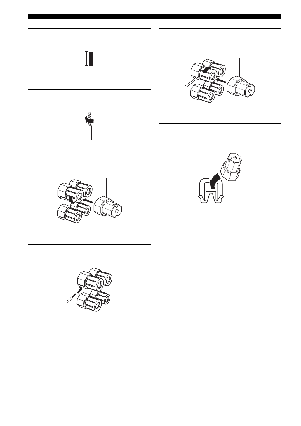
1 Remove approximately 10 mm (3/8 in) of
insulation from each of the speaker cables.
10 mm (3/8 in)
2 Twist the exposed wires of the cable together
to prevent short circuits.
3 Loosen the knob using the supplied speaker
terminal wrench.
Speaker terminal wrench
5 Tighten the knob to secure the wire using the
supplied speaker terminal wrench.
Speaker terminal wrench
Red: positive (+)
Black: negative (–)
6 Hook the speaker terminal wrench onto
WRENCH HOLDER on the rear panel of this
unit when not in use.
Red: positive (+)
Black: negative (–)
4 Insert one bare wire into the hole on the side
of each terminal.
Red: positive (+)
Black: negative (–)
16
Page 21
CONNECTIONS
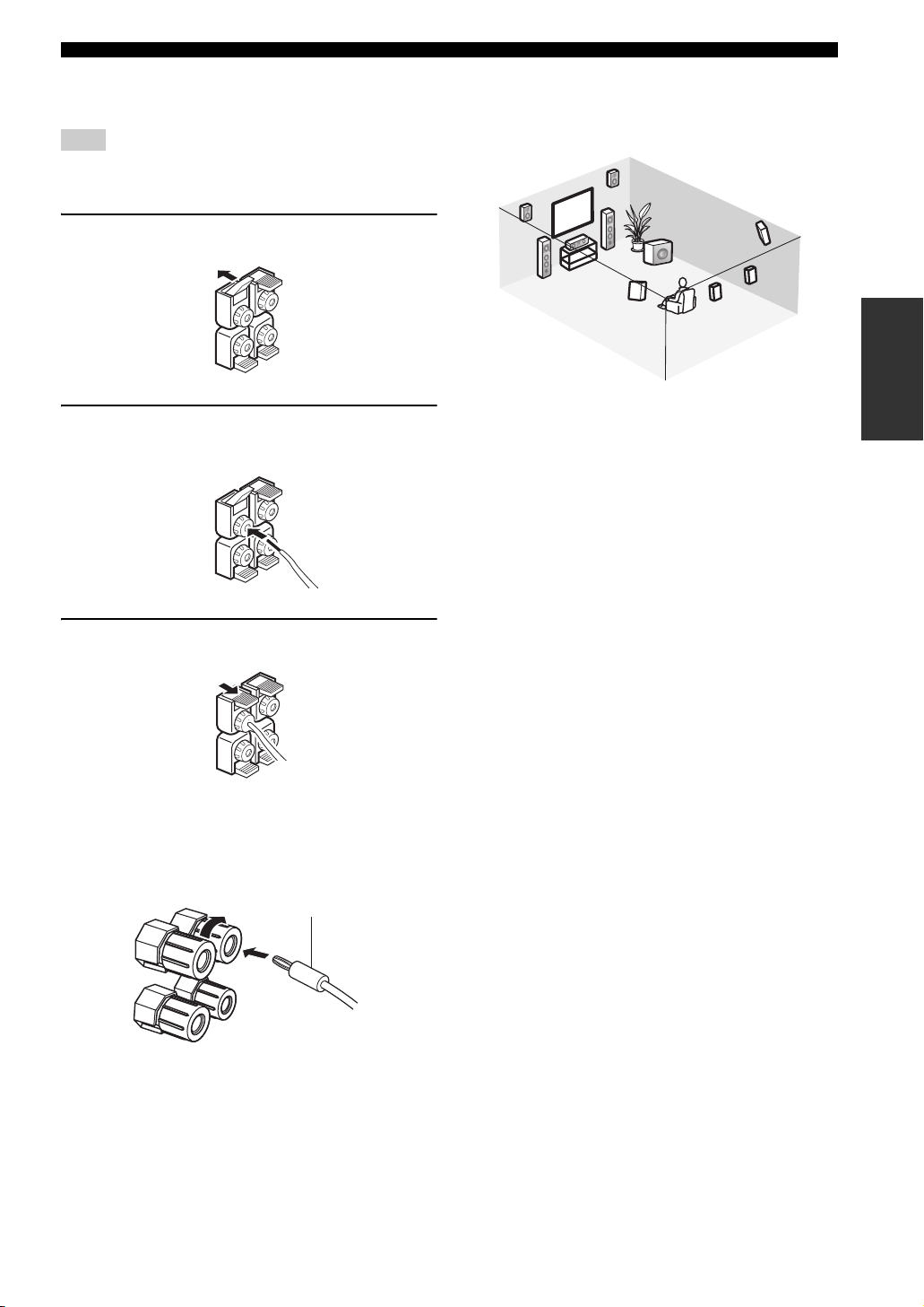
PRESENCE/ZONE 2(3) terminals
Connect presence speakers to these terminals.
Note
You can also use these terminals to connect the Zone 2 speakers
(see page 116).
1 Open the tab.
2 Insert one bare wire into the hole of each
terminal.
3 Return the tab to secure the wire.
■ Speaker layout
Refer to the following illustration as to where to place
each speaker in your listening room.
9
10
3
1 Subwoofer
2 Front right speaker
3 Front left speaker
4 Center speaker
5 Surround back right speaker
6 Surround back left speaker
7 Surround right speaker
8 Surround left speaker
9 Presence right speaker
10 Presence left speaker
2
4
1
8
7
5
6
PREPARATION
■ Connecting the banana plug
(With the exception of U.K., Europe and Asia models)
First, tighten the knob and then insert the banana plug
connector into the end of the corresponding terminal.
Banana plug
(With the exception of U.K., Europe and Asia models)
y
You can also use banana plugs with the PRESENCE/ZONE 2(3)
speaker terminals. Open the tab and then insert one banana plug
connector into the hole of each terminal. Do not attempt to close
the tabs after connecting the banana plugs.
17
Page 22
CONNECTIONS
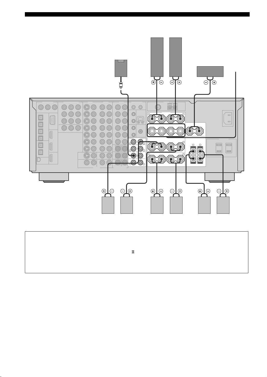
(U.S.A. model)
Subwoofer with
built-in amplifier
Front speakers (A)
LeftRight
Center
speaker
Front
speakers
(B)
FRONT
R
SURROUND
R
SUBWOOFER
R
SURROUND BACK/PRESENCE
LeftRight LeftRight
Surround speakers
SPEAKERS
+
–
R
FRONT
+
–
PRE OUT
CENTER
SINGLE
SURROUND/ZONE 2(3)
+
R
L
L
(SB)
L
–
+
R
SURROUND BACK
Surround back speakers
+
–
A
B
L
CENTER
+
–
++––
L
+
–
L
SINGLE
–
SPEAKER IMPEDANCE
R
–
PRESENCE/ZONE 2(3)
+
L
LeftRight
Presence speakers
• You can connect both surround back and presence speakers to this unit, but they do not output sound simultaneously. You can set
to prioritize either set of speakers using the PR/SB Priority parameter in Manual Setup (see page 86).
• The surround back speakers output the surround back channel included in Dolby Digital EX and DTS-ES software and operate
only when the Dolby Digital EX, DTS-ES, Dolby Pro Logic x, THX Select2, THX Music, THX Games or THX Surround EX
decoder is turned on.
• The presence speakers output ambient effects created by the DSP sound fields. They do not output sound when other sound fields
are selected.
18
Page 23
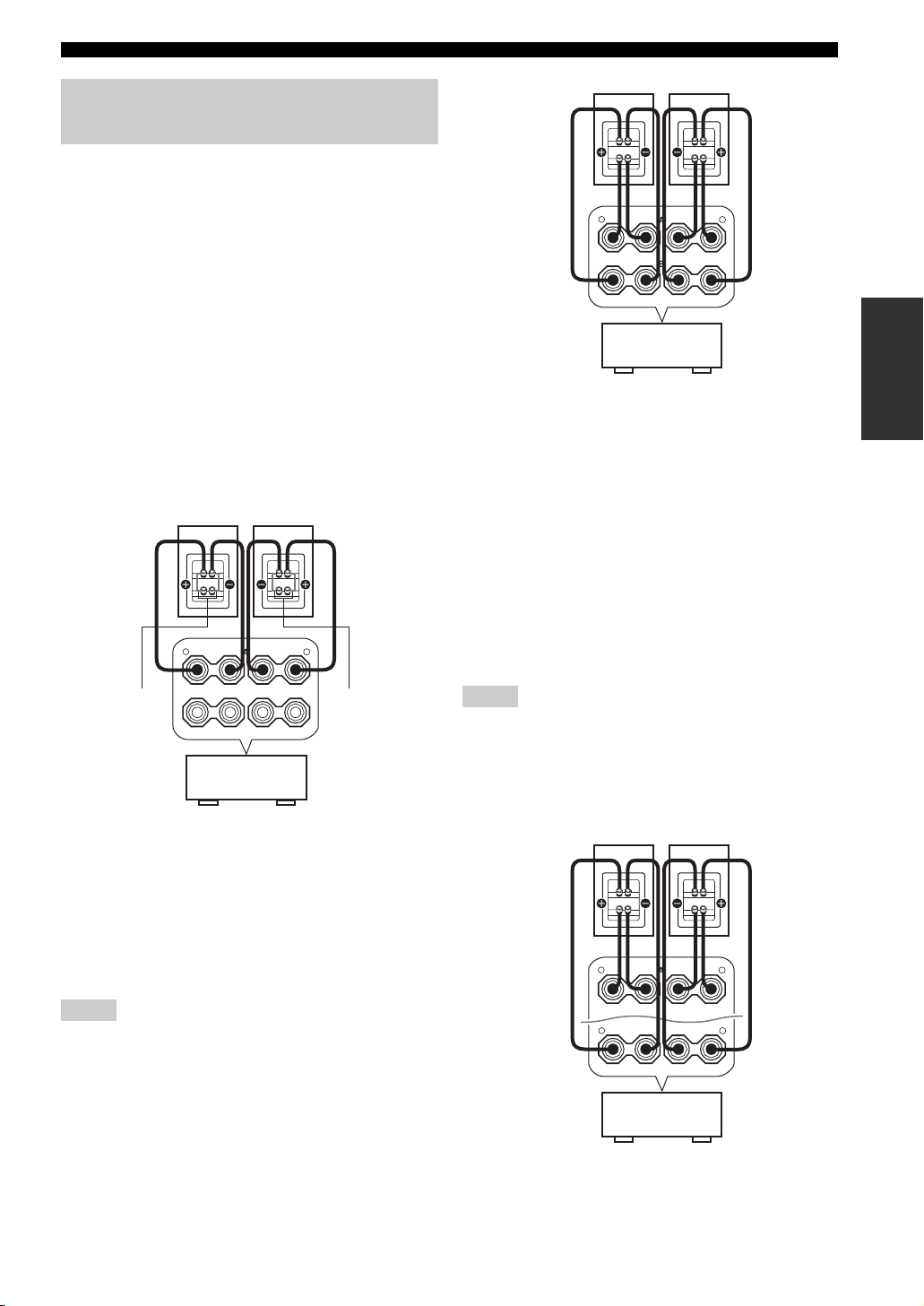
Using bi-wire and bi-AMP connections
Some of the speakers commercially available these days
have speaker wire connections that allow bi-wiring or biamplification to enhance the performance of the speaker
system. This unit allows you to make bi-wire and bi-AMP
connections to one speaker system. Check if your speakers
support bi-wiring or bi-amplification. As these speakers
are shipped to you, you will note gold-plated shorting bars
or bridges, one connecting the two red input terminals and
the other connecting the two black input terminals.
Remove these shorting bars or bridges only if you plan to
bi-wire or bi-AMP your speakers.
FRONT
R
++–
A
–
B
This unit
CONNECTIONS
+
–
L
+
–
PREPARATION
■ Conventional connection
If you want to connect your speakers as traditional
loudspeakers using the conventional connection method,
connect your speakers using the regular left and right
speaker wire connections and ignore the second set of
terminals.
+
A
–
B
This unit
–
L
+
–
Shorting bars
or bridges
Shorting bars
or bridges
FRONT
R
++–
■ Bi-wire connection
The bi-wire connection separates the woofer from the
combined midrange and tweeter section. A bi-wire
compatible speaker has four binding post terminals. These
two sets of terminals allow the speaker to be split into two
independent sections. This split connects the mid and high
frequency drivers to one set of terminals and the low
frequency driver to the other pair.
■ Bi-AMP connection
The bi-AMP connection uses two amplifiers for both
speakers. One amplifier is connected to the woofer section
of a loudspeaker while the other is connected to the
combined mid and tweeter section. With this arrangement
each amplifier operates over a restricted frequency range.
This restricted range presents each amplifier with a much
simpler job and each amplifier is less likely to influence
the sound in some way. The internal crossover of the
speaker consists of a LPF (low pass filter) and a HPF (high
pass filter). As its name implies, the LPF passes
frequencies below a cutoff and rejects frequencies above
the cutoff frequency. Likewise, the HPF passes
frequencies above its cutoff.
Notes
• Remove the shorting bars or bridges to separate the LPF (low
pass filter) and HPF (high pass filter) crossovers.
• To activate the bi-AMP connections, set BI-AMP to ON in
ADVANCED SETUP (see page 102).
• To make the bi-AMP connections, use the FRONT and
SURROUND BACK terminals as shown below.
+
+
R
–
–
A
L
Notes
• Remove the shorting bars or bridges to separate the LPF (low
pass filter) and HPF (high pass filter) crossovers.
• To use the bi-wire connections, press SPEAKERS A on the
front panel so that SP A lights up in the front panel display.
FRONT
R
+
–
SURROUND BACK
This unit
+
–
L
SINGLE
19
Page 24
CONNECTIONS
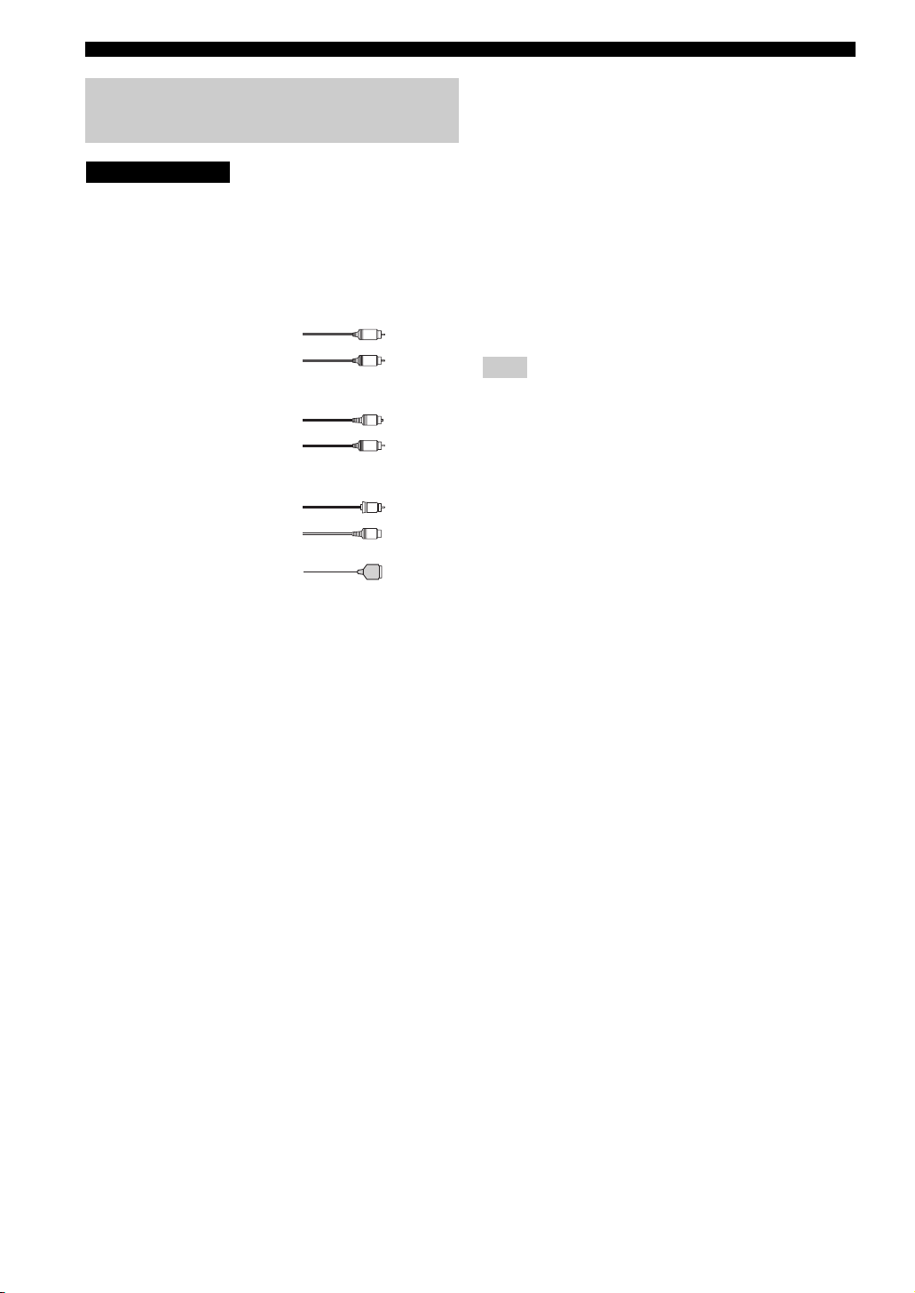
Information on cables and jacks used for connections
CAUTION
Do not connect this unit or other components to the main
power until all connections between components are
complete.
■ Cable indications
For analog signals
left analog cables
right analog cables
For digital signals
optical cables
coaxial cables
For video signals
video cables
S-video cables
L
R
O
C
V
S
■ Analog jacks
You can input analog signals from audio components by
connecting audio pin cables to the analog jacks on this
unit. Connect red plugs to the right jacks and white plugs
to the left jacks.
■ Digital jacks
This unit has digital jacks for direct transmission of digital
signals through either coaxial or fiber optic cables. You
can use the digital jacks to input PCM, Dolby Digital and
DTS bitstreams. When you connect components to both
the COAXIAL and OPTICAL jacks, priority is given to
signals input at the COAXIAL jack. All digital input jacks
are compatible with 96-kHz sampling digital signals.
Note
This unit handles digital and analog signals independently. Thus
audio signals input at the analog jacks are only output at the
analog OUT (REC) jacks. Likewise, audio signals input at the
digital (OPTICAL or COAXIAL) jacks are only output at the
DIGITAL OUTPUT jacks.
For HDMI signals
20
Page 25
CONNECTIONS
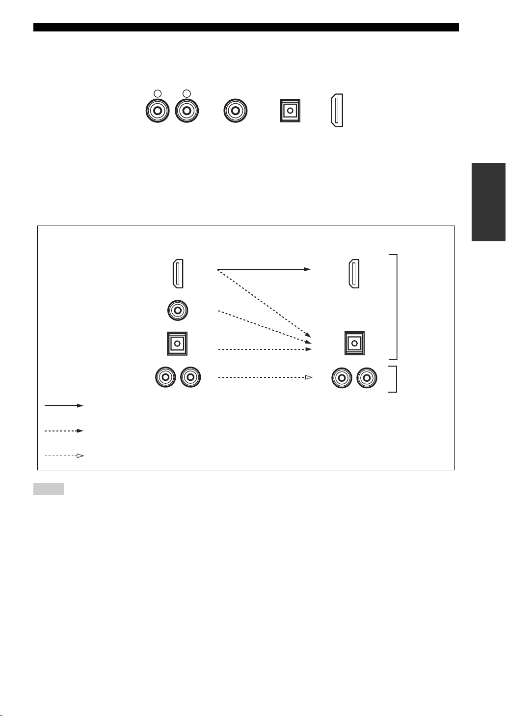
■ Audio jacks
This unit has four types of audio jacks (analog audio, digital audio coaxial, digital audio optical and HDMI). Connection
depends on the availability of audio jacks on your other components.
AUDIO
R
L
DIGITAL AUDIO
AUDIO jacks
For conventional analog audio signals.
DIGITAL AUDIO (COAXIAL) jacks
For digital audio signals transmitted via digital coaxial
cables.
■ Audio signal flow for OUT (REC)
Input
HDMI
DIGITAL AUDIO
(COAXIAL)
DIGITAL AUDIO
(OPTICAL)
(COAXIAL)
DIGITAL AUDIO
(OPTICAL)
HDMI
DIGITAL AUDIO (OPTICAL) jacks
For digital audio signals transmitted via digital optical
cables.
HDMI jacks
For HDMI digital audio signals.
Output
OUT (REC)
Digital audio
PREPARATION
AUDIO
Through
Digital output
Analog output
Analog audio
Notes
• The audio signals input at the HDMI IN 1 or HDMI IN 2 jack are output at the DIGITAL OUTPUT jacks only and are not output at the
analog OUT (REC) jacks.
• 2-channel as well as multi-channel PCM, Dolby Digital and DTS signals input at the HDMI IN 1 or HDMI IN 2 jack can be output at
the HDMI OUT jack only when HDMI Set is set to Other (see page 99).
• 2-channel PCM, Dolby Digital and DTS signals except multi-channel PCM signals input at the HDMI IN 1 or HDMI IN 2 jack can be
output at the DIGITAL AUDIO (OPTICAL) jacks.
• Copy-protected 2-channel PCM signals with over 48 kHz/16 bit input at the HDMI IN 1 or HDMI IN 2 jack are not output at the
DIGITAL AUDIO (OPTICAL) jacks.
21
Page 26
CONNECTIONS
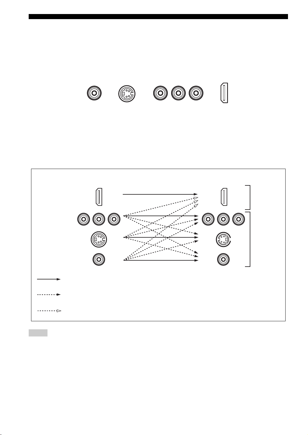
■ Video jacks
This unit has four types of video jacks (composite, component, S-video and HDMI). Connection depends on the
availability of input jacks on your monitor. When Conversion is set to On (see page 88), the analog video signals input at
the VIDEO, S VIDEO and COMPONENT VIDEO jacks can be output at the VIDEO, S VIDEO and COMPONENT
VIDEO jacks interchangeably. In addition, when Conversion
On (see page 88), the analog video signals input at the VIDEO, S VIDEO and COMPONENT VIDEO jacks can be
digitally up-converted and output at the HDMI OUT jack.
VIDEO
S VIDEO
is set to On (see page 88) and HDMI Up-Scaling is set to
COMPONENT VIDEO
Y PBP
R
HDMI
VIDEO jacks
For conventional composite video signals.
S VIDEO jacks
For S-video signals, separated into luminance (Y) and
color (C) video signals to achieve high-quality color
reproduction.
■ Video signal flow for MONITOR OUT
Input
HDMI
COMPONENT
VIDEO
S VIDEO
VIDEO
Through
COMPONENT VIDEO jacks
For component signals, separated into luminance (Y) and
color difference (P
B, PR) to provide the best quality in
picture reproduction.
HDMI jacks
For HDMI digital video signals.
Output
(MONITOR OUT)
Digital video
Analog video
Component I/P (see page 88) only when Conversion is set to On (see page 88)
HDMI Up-Scaling (see page 88) only when Conversion is set to On (see page 88)
Notes
• The analog video signals output at the COMPONENT VIDEO jacks can be deinterlaced from 480i to 480p. Set Component I/P to On
in Manual Setup to activate this feature (see page 88).
• The analog video signals input at the COMPONENT VIDEO jacks and output at the S VIDEO or VIDEO jacks cannot be converted to
480p/1080i/720p.
• The analog video signals output at the HDMI jack can be up-scaled to 480p/1080i/720p.
• When the analog video signals are input at the COMPONENT VIDEO, S VIDEO and VIDEO jacks, the priority order of the input
signals is as follows where the analog video signals input at the COMPONENT VIDEO jacks have the top priority.
1. COMPONENT VIDEO
2. S VIDEO
3. VIDEO
22
Page 27
CONNECTIONS
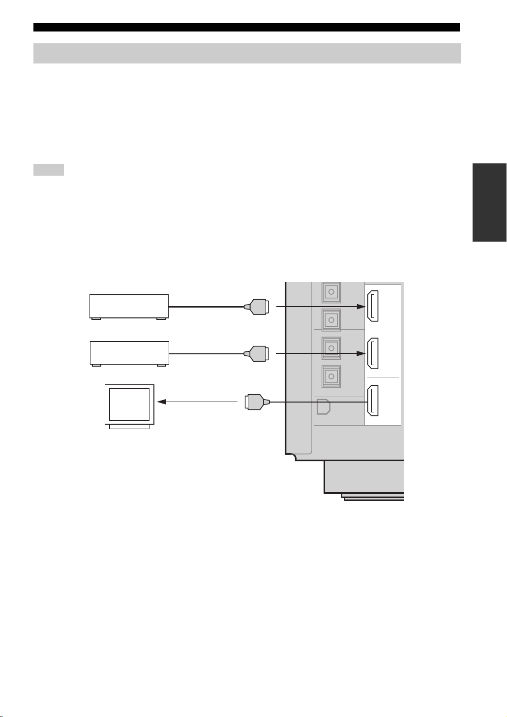
Connecting HDMI components
This unit has the HDMI IN 1 and HDMI IN 2 jacks for digital audio and video signal input as well as the HDMI OUT
jack for digital audio and video signal output. Connect the HDMI IN 1 or HDMI IN 2 jack of this unit to the HDMI OUT
jack of other HDMI components (such as a DVD player). Connect the HDMI OUT jack of this unit to the HDMI IN jack
of other HDMI components (such as a TV and a projector).
The video or audio signals input at the HDMI IN 1 or HDMI IN 2 jack you selected using the HDMI IN menu in I/O
Assignment (see page 81) or the INPUT selector on the front panel are output at the HDMI OUT jack of this unit. In
addition, the audio signals input at the HDMI IN 1 or HDMI IN 2 jack are output to speakers, headphones and the
DIGITAL OUTPUT jacks.
Notes
• We recommend using an HDMI cable shorter than 5 meters (16 feet) with the HDMI logo printed on it.
• Digital audio signals input at the HDMI IN jacks are not output at the analog AUDIO OUT jacks.
• Some audio signals may not be output at the DIGITAL OUTPUT jacks depending on the signal type.
• The analog video signals input at the composite video, S-video and component video jacks can be digitally up-converted and up-scaled
to 480p/1080i/720p to be output at the HDMI OUT jack. Set Conversion to On in Manual Setup (see page 88) and adjust settings for
HDMI Up-Scaling to activate this feature (see page 88).
• Some video monitors connected to this unit via a DVI connection fail to recognize the HDMI audio signals being input if they are in
the standby mode. In this case, the HDMI indicator flashes irregularly and HDCP ERROR appears in the front panel display as if the
DVI monitors do not support the HDCP copy protection standards.
IN 1
IN 2
OUT
HDMI
DVD Player
Cable TV or
Satellite tuner
Video
monitor
HDMI out
HDMI out
HDMI in
PREPARATION
(U.S.A. model)
23
Page 28
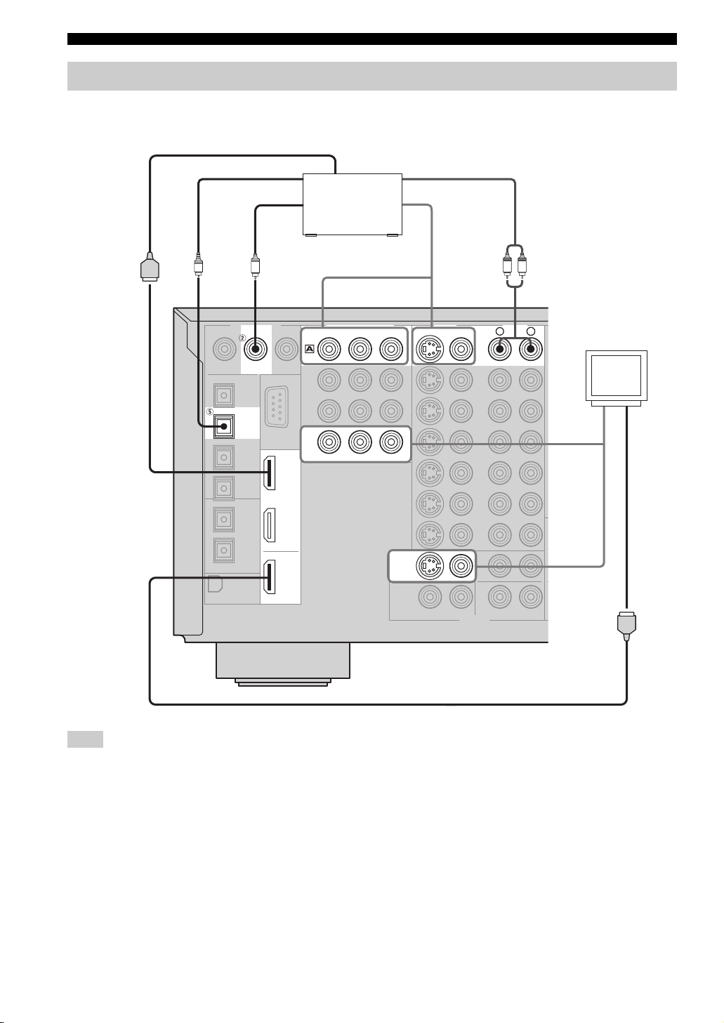
CONNECTIONS
Connecting video components
■ Connecting a DVD player
HDMI out
Optical out
Audio out
O
DVD
DIGITAL OUTPUT
Coaxial out
C
DIGITAL INPUT
DVD
OPTICAL
COAXIAL
IN 1
IN 2
OUT
DVD player
COMPONENT VIDEO
DVD
PBY
MONITOR OUT
PR
MONITOR
OUT
Video out
S VIDEO
VIDEO
LR
AUDI OVIDEO
R
L
DVD
Video
monitor
Video in
HDMI
OUTPUT
(U.S.A. model)
HDMI in
Note
Check the availability of jacks on your DVD player and select one type of connection for audio/video input/output. However, in case
you make an HDMI connection, you can make both audio and video connections using a single HDMI cable.
24
Page 29
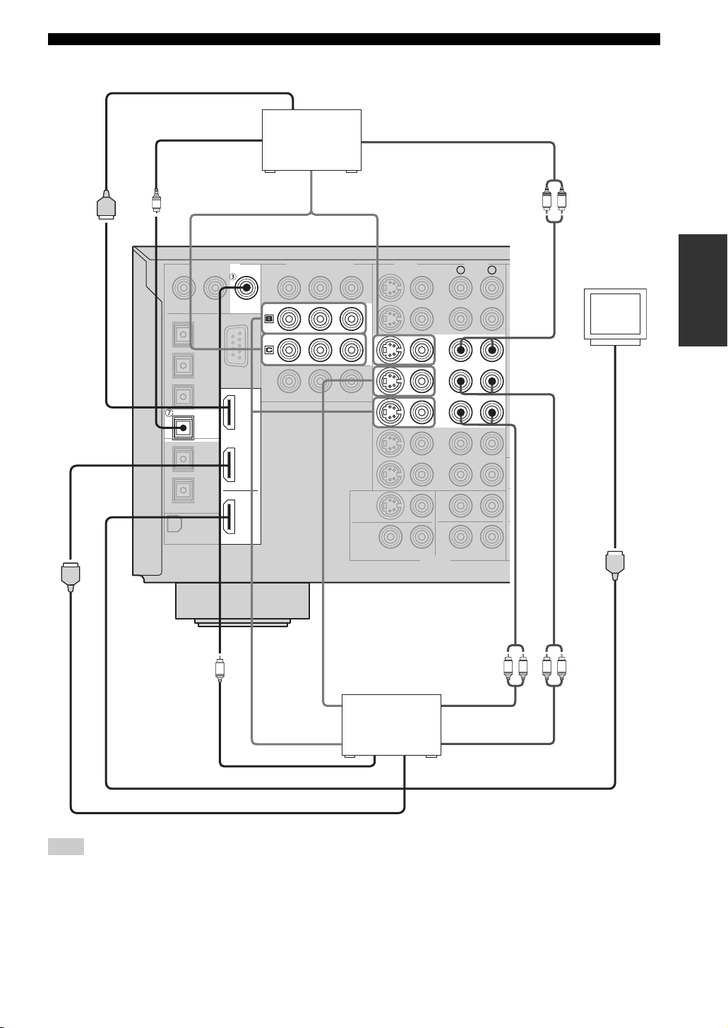
■ Connecting other video components
HDMI out
Cable TV or
COAXIAL
DVR/
VCR 2
IN 1
satellite tuner
COMPONENT VIDEO
DTV
CBL/
SAT
Optical out
O
DIGITAL INPUT
OPTICAL
CBL/SAT
Video out
PRPBY
Audio out
S VIDEO
VIDEO
CBL/
SAT
IN
VCR 1
OUT
CONNECTIONS
LR
PREPARATION
AUDIOVIDEO
R
L
Video
monitor
IN 2
OUT
HDMI
(U.S.A. model)
C
LR LR
Audio in
Video out
DVD recorder
or VCR
Audio out
Video out
Coaxial out
HDMI in
HDMI out
Note
Check the availability of jacks on your other video components and select one type of connection for audio/video input/output.
However, in case you make an HDMI connection, you can make both audio and video connections using a single HDMI cable.
25
Page 30
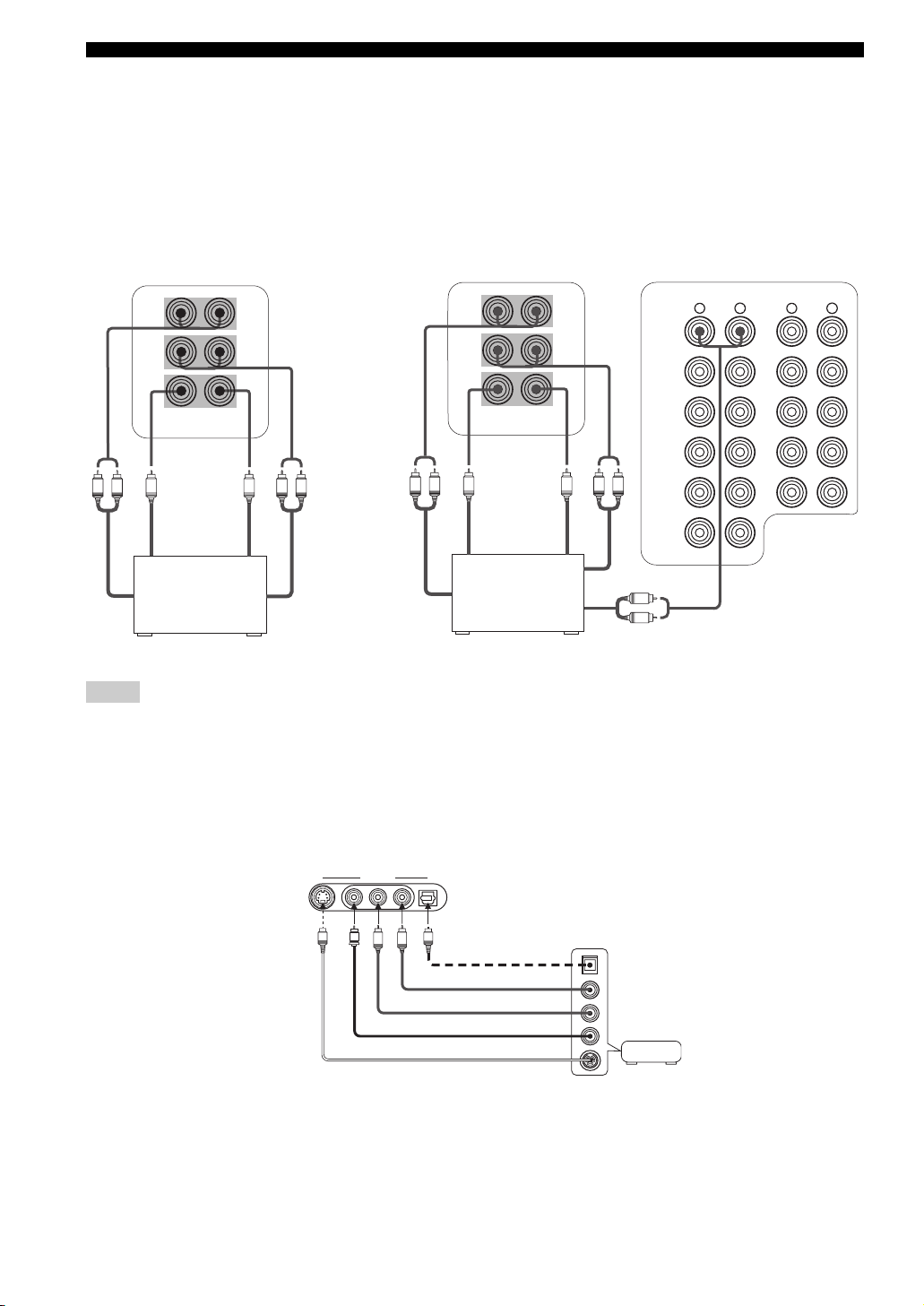
CONNECTIONS
■ Connecting to the MULTI CH INPUT jacks
This unit is equipped with 6 additional input jacks (left and right FRONT, CENTER, left and right SURROUND and
SUBWOOFER) for discrete multi-channel input from a multi-format player, external decoder, sound processor or
pre-amplifier.
If you set INPUT CH to 8ch in Multi CH Assign (see page 82), you can use the input jacks assigned as FRONT INPUT
in Multi CH Assign (see page 82) together with the MULTI CH INPUT jacks to input 8-channel signals.
Connect the output jacks on your multi-format player or external decoder to the MULTI CH INPUT jacks. Be sure to
match the left and right outputs to the left and right input jacks for the front and surround channels.
For 6-channel input For 8-channel input
FRONT(6CH)/SB(8CH)
SURROUND
SUBWOOFER
MULTI CH INPUT
Subwoofer
LR
out
Multi-format player/
External decoder
Front
out
CENTER
Center
out
LR
Surround
out
Surround
back out
FRONT(6CH)/SB(8CH)
SURROUND
CENTER
SUBWOOFER
MULTI CH INPUT
Subwoofer
out
Center
out
Multi-format player/
External decoder
LRLR
Surround out
R
L
Front out
DVD
DTV
CBL/
SAT
IN
VCR 1
OUT
IN
DVR/VCR 2
AUDIO
R
L
(
)
PLAY
IN
MD/TAPE
OUT
(REC)
(
)
PLAY
IN
CD-R
OUT
(REC)
CD
AUDIO
R
L
Notes
• When you select MULTI CH INPUT as the input source, this unit automatically turns off the digital sound field processor, and you
cannot select sound field programs.
• This unit does not redirect signals input at the MULTI CH INPUT jacks to accommodate for missing speakers. We recommend that
you connect at least a 5.1-channel speaker system before using this feature.
• When headphones are used, only front L/R channels are output.
■ Connecting to the VIDEO AUX jacks on the front panel
Use these jacks to connect any video source, such as a game console or video camera, to this unit.
VIDEO AUX
S VIDEO VIDEO OPTICALL AUDIO R
V
S
O
L
R
Optical out
Audio out R
Audio out L
Video out
Game
console or
video camera
S-video out
26
Page 31

Connecting audio components
Optical in
CD recorder
CONNECTIONS
O
Optical in
MD recorder or
tape deck
Audio in
O
DIGITAL INPUT
CD
OPTICAL
CD
MD/TAPE
CD-R
DIGITAL OUTPUT
COAXIAL
Audio out
(U.S.A. model)
LRLRLR LR
AUDIO
R
(PLAY)
IN
MD/TAPE
OUT
(REC)
(PLAY)
IN
CD-R
OUT
(REC)
CD
PHONO
Audio inAudio out
PREPARATION
L
GND
LRLR
Audio out
Optical out
O
Coaxial out
C
Audio out
CD player
GND
Turntable
Notes
• Check the availability of jacks on your audio components and select one type of connection for audio/video input/output.
• PHONO jacks are for connecting a turntable with an MM or high-output MC cartridge. If you have a turntable with a low-output MC
cartridge, use an in-line boosting transformer or MC-head amplifier when connecting to these jacks.
• Connect your turntable to the GND terminal to reduce noise in the signal. However you may hear less noise without the connection to
the GND terminal for some record players.
27
Page 32

CONNECTIONS
■ Connecting an external amplifier
If you want to increase the power output to the speakers,
or want to use another amplifier, connect an external
amplifier to the PRE OUT jacks as follows.
Notes
• When audio pin plugs are connected to the PRE OUT jacks for
output to an external amplifier, it is not necessary to use the
corresponding SPEAKERS terminals. Set the volume of the
external amplifier connected to this unit to the maximum.
• The signal output at the FRONT PRE OUT and CENTER PRE
OUT jacks are affected by the TONE CONTROL settings.
• If SPEAKERS A is turned off and SPEAKERS B is set to Zone
B (see page 95), signals will only be output at the FRONT PRE
OUT jacks.
PRE OUT
FRONT
1
2
3
4
R
SURROUND
R
SUBWOOFER
R
SURROUND BACK/PRESENCE
CENTER
SINGLE
L
L
5
(SB)
L
1 FRONT PRE OUT jacks
Front channel line output jacks.
2 SURROUND PRE OUT jacks
Surround channel line output jacks.
3 SUBWOOFER PRE OUT jack
Connect a subwoofer with built-in amplifier, such as the
YAMAHA Active Servo Processing Subwoofer System,
to this jack.
4 SURROUND BACK/PRESENCE PRE OUT
jacks
Surround back or presence channel line output jacks. If
you only connect one external amplifier for the surround
back channel, connect it to the left (L) jack.
5 CENTER PRE OUT jack
Center channel line output jack.
Notes
• Each PRE OUT jack outputs the same channel signal as the
corresponding speaker terminals. However, when both surround
back and presence speakers are setup in this unit, the signals
output at SURROUND BACK/PRESENCE PRE OUT jacks
may not correspond to the correct speakers.
• Adjust the volume level of the subwoofer with the control on
the subwoofer.
• Some signals may not be output at the SUBWOOFER PRE
OUT jack depending on the Speaker Set settings (see page 90).
28
Page 33

CONNECTIONS
Connecting the antennas
Both AM and FM indoor antennas are included with this unit. In general, these antennas should provide sufficient signal
strength. Connect each antenna correctly to the designated terminals.
Ground (GND terminal)
For maximum safety and minimum interference,
connect the antenna
ground. A good earth ground is a metal stake driven
into moist earth.
GND terminal to a good earth
■ Connecting the AM loop antenna
1 Set up the AM loop antenna.
Indoor FM antenna
(included)
3 Orient the AM loop antenna for the best
reception.
FM ANT
75Ω
UNBAL.
TUNER
AM ANTGND
(U.S.A. model)
AM loop antenna
(included)
PREPARATION
2 Press and hold the tab to insert the AM loop
antenna lead wires into the AM ANT and GND
terminals.
Notes
• The AM loop antenna should be placed away from this unit.
• The AM loop antenna should always be connected, even if an
outdoor AM antenna is connected to this unit.
• A property installed outdoor antenna provides clearer reception
than an indoor one. If you experience poor reception quality, an
outdoor antenna may improve the quality. Consult the nearest
authorized YAMAHA dealer or service center about outdoor
antennas.
29
Page 34

CONNECTIONS
Connecting the power cable
■ Connecting the AC power cable
Plug the supplied AC power cable into the AC inlet after
all other connections are complete and then plug the AC
power cable to an AC wall outlet.
CAUTION
Use the supplied AC cable. Do not use other AC power cables as
doing so may result in fire hazard or electrical shock.
AC IN
AC OUTLETS
100W MAX.TOTAL
SWITCHED
Turning on and off this unit
When all connections are complete, turn on the power of
this unit.
2,3
MULTI CH
AUDIO
INPUT
SELECT
INPUTMAIN ZONE
ON/OFF
MASTER
ON OFF
SOURCE/
REMOTE
MD/TAPEDVD
CD-R
DTV
CD
CBL/SAT
VCR 1
PHONO
DVR/
TUNER
VCR 2
V-AUX
REC OUT/ZONE 2
A/B/C/D/E
CATEGORY
SPEAKERS
A
B
YPAO
SILENT CINEMA S VIDEO VIDEO L
OPTIMIZER
MIC
PRESET/TUNING/CH
PHONES
PRESET/
MEMORY
FM/AM
TUNING
EDIT
MAN'L/AUTO FM
SEARCH MODE
DISPLAY
AUTO/MAN'L EFFECT
ZONE ON/OFF
ZONE CONTROL
MULTI ZONE
ZONE 2
ZONE 3
AUDIO R OPTICA L
VIDEO/AUX
1,4
1 Press MASTER ON/OFF on the front panel
inward to the ON position to turn on the
power of this unit.
• Only this unit is turned on.
• Zone 2 and Zone 3 are set to the standby mode.
MASTER
ON
OFF
(U.S.A. model)
PURE DIRECT
VOLUME
TONE
TUNING
CONTROL
STRAIGHT
MODE
PROGRAM
(U.S.A. model)
■ AC OUTLETS (SWITCHED)
Use these 2 outlets to supply power to any connected
components. Connect the AC power cables of your other
components to these 2 outlets. Power to these 2 outlets is
supplied when the main room, Zone 2 or Zone 3 is turned
on. However, power to these 2 outlets is cut off when the
main room, Zone 2 and Zone 3 are turned off or when
MASTER ON/OFF on the front panel is pressed and
released outward to the OFF position. The maximum
power or the total power consumption of the components
that can be connected to these 2 outlets is 100 W.
Memory back-up
The memory back-up circuit prevents the stored data
from being lost. However, the stored data will be lost
in case the power cord is disconnected from the AC
wall outlet for more than one week.
2 Press MAIN ZONE ON/OFF on the front panel
(or STANDBY on the remote control) to set
this unit to the standby mode.
ON/OFF
or
Front panel Remote control
STANDBY
30
Page 35

CONNECTIONS
3 Press MAIN ZONE ON/OFF, ZONE 2 ON/OFF
or ZONE 3 ON/OFF on the front panel (or
POWER on the remote control) to turn on this
unit, Zone 2 or Zone 3.
ON/OFF
Front panel Remote control
or
POWER
y
• When MASTER ON/OFF is pressed inward to the ON
position, you can also press POWER or STANDBY on the
remote control to turn on or set this unit, Zone 2 and Zone
3 to the standby mode simultaneously.
• For details about controlling Zone 2 and Zone 3 using the
remote control, see page 117.
Note
MAIN ZONE ON/OFF, ZONE 2 ON/OFF and ZONE 3
ON/OFF on the front panel as well as POWER and
STANDBY on the remote control are operational only when
MASTER ON/OFF is pressed inward to the ON position.
4 Press MASTER ON/OFF on the front panel
again to release it outward to the OFF
position to turn off this unit.
This unit, Zone 2 and Zone 3 are turned off.
MASTER
ON
OFF
Setting the speaker impedance
Follow the procedure below to change the impedance
setting for all speakers.
CAUTION
If you are using 6 ohm speakers, set the impedance to
6 ohms before using this unit.
1 Press MASTER ON/OFF on the front panel to
release it outward to the OFF position to set
this unit, Zone 2 and Zone 3 to the standby
mode.
MASTER
ON
OFF
2 Press and hold STRAIGHT (EFFECT) on the
front panel and then press MASTER ON/OFF
inward to the ON position to turn on the
power of this unit.
SP IMP.–8ΩMIN appears in the front panel display.
ON
MASTER
OFF
STRAIGHT
EFFECT
ADVANCED SETUP
SP IMP.-8 MIN
PREPARATION
3 Press STRAIGHT (EFFECT) on the front
panel repeatedly to select the impedance of
your speakers.
STRAIGHT
EFFECT
• Select 6 ohms if you are using 6 ohm speakers.
• Select 8 ohms if you are using 8 ohm speakers.
4 Press MASTER ON/OFF on the front panel to
release it outward to the OFF position to save
the new setting and set this unit, Zone 2 and
Zone 3 to the standby mode.
This unit will be set to the standby mode.
MASTER
ON
OFF
Note
You can also set the speaker impedance by using the SP
IMP. parameter in the ADVANCED SETUP menu (see
page 101).
31
Page 36

AUTO SETUP
AUTO SETUP
Introduction
This receiver employs YAMAHA Parametric Room
Acoustic Optimizer (YPAO) technology which lets you
avoid troublesome listening-based speaker setup and
achieves highly accurate sound adjustments. The supplied
optimizer microphone collects and analyzes the sound
your speakers produce in your actual listening
environment.
Notes
• Please be advised that it is normal for loud test tones to be
output during the AUTO SETUP procedure.
• If the AUTO SETUP procedure stops and error messages
appear on the screen, follow the troubleshooting on page 126.
YPAO performs the following checks and makes
appropriate adjustments to give you the best possible
sound from your system.
Wiring
Checks which speakers are connected and the polarity of
each speaker.
Distance
Checks the distance of each speaker from the listening
position and adjusts the timing of each channel.
Size
Checks the speaker’s frequency response and sets the
appropriate low frequency crossover for each channel.
Equalizing
Adjusts frequency and levels of each channel’s parametric
equalizer to reduce coloration across the channels and
create a cohesive sound field. This is particularly
important if you use different brands or sizes of speakers
for some channels or have a room with unique sonic
characteristics.
YPAO equalizing calibration incorporates three
parameters (frequency, level and Q factor) for each of the
seven bands in its parametric equalizer to provide highly
precise automatic adjustment of frequency characteristics.
Level
Checks and adjusts the volume level of each speaker.
Optimizer microphone setup
1 Connect the supplied optimizer microphone
to the OPTIMIZER MIC jack on the front
panel.
MULTI CH
SELECT
CBL/SAT
VCR 1
AUDIO
DTV
DVR/
VCR 2
V-AUX
REC OUT/ZONE 2
SOURCE/
REMOTE
INPUT
A/B/C/D/E
CATEGORY
SPEAKERS
MD/TAPEDVD
CD-R
A
B
CD
YPAO
SILENT CINEMA S VIDEO VIDEO L
PHONO
TUNER
OPTIMIZER
MIC
PRESET/TUNING/CH
PHONES
MULTI ZONE
EDIT
PRESET/
TUNING
SEARCH MODE
FM/AM
DISPLAY
ZONE 2
VIDEO/AUX
MEMORY
MAN'L/AUTO FM
ZONE ON/OFF
ZONE 3
AUDIO R OPTICAL
TUNING
MODE
AUTO/MAN'L EFFECT
ZONE CONTROL
Notes
• After you have completed the AUTO SETUP procedure, be sure
to disconnect the optimizer microphone.
• The optimizer microphone is sensitive to heat.
– Keep it away from direct sunlight.
– Do not place it on top of this unit.
2 Place the optimizer microphone on a flat
level surface with the omni-directional
microphone head upward, at your normal
listening position.
If possible, use a tripod (etc.) to affix the optimizer
mic at the same height as your ears would be when
you are seated in your listening position.
Optimizer microphone position
STRAIGHT
PROGRAM
CONTROL
TONE
32
Page 37

AUTO SETUP
CLEAR
LEARN
RE–NAME
REC
DISC SKIP
1
2B
THX
STANDARD SELECT EXTD SUR.
STEREO
MUSIC ENTERTAIN MOVIE
3421
90
+10
ENT.
5678
MACROONOFF
A
SPEAKERSMEMORY
EXIT
PURE DIRECT
TOP
SELECT
VOLUME
+
–
POWER POWER
POWER
STANDBY
AVTV
SLEEP
AUDIO SEL
CH
+
–
TV VOL
TV MUTE TV INPUT
MUTE
+
–
AMP
SOURCE
TV
PRESET
Using AUTO SETUP
For best results, make sure the room is as quiet as possible
during the AUTO SETUP procedure (YPAO). If there is
too much ambient noise, the results may not be
satisfactory.
y
• You can run AUTO SETUP using the system menu that appears
in the GUI or in the front panel display. This manual uses the
GUI illustrations to explain the AUTO SETUP procedure.
• If an error occurs during the AUTO SETUP procedure and an
error message appears in the front panel display, see pages 126
and 127 for a complete list of error messages and proper
remedies.
• If your subwoofer can adjust the output volume and the
crossover frequency, set the volume to about half way (or
slightly less) and set the crossover frequency to the maximum.
CROSSOVER
GUI TOP
TITLE
RETURN
XM MEMORY
HIGH CUT
MAX
MIN
PRESET/CH
EXIT
PURE DIRECT
MENU
BAND
SRCH MODE
NIGHT
STRAIGHT
2
AUDIO
3-9
EFFECT
ENTER
A-E/CAT.
DISPLAY
MIN
XM
A
PHONO TUNER CD
V-AUX
CBL/SAT MD/TAPE
DTV DVR/VCR2VCR 1 DVD
VOLUME
MAX
Subwoofer
MULTI CH IN
CD-R
1 Switch on this unit and video monitor.
2 Set AMP/SOURCE/TV to AMP and then press
GUI TOP on the remote control.
The top display appears.
AMP
SOURCE
TV
Stereo/Surround
Input Select
Manual Setup
Auto Setup
System Memory
Sound
Video
Basic
Option
GUI TOP
TITLE
BAND
3 Press k / n repeatedly to select Auto Setup
and then press h.
PRESET/CH
ENTER
A-E/CAT.
PRESET/CH
ENTER
A-E/CAT.
PREPARATION
(U.S.A. model)
Input Select
2
Manual Setup
Auto Setup
System Memory
Signal Info.
Information
Setup Menu
Setup Type
Start
4 Press k / n repeatedly to select Setup Menu
and then press h.
Information
Setup Menu
Setup Type
Start
Wiring
Distance
Size
33
Page 38

AUTO SETUP
5 Press k / n repeatedly to select Wiring,
Distance, Size, Equalizing or Level and then
press h.
Skip
Wiring
Distance
Size
Wiring
Distance
Size
Equalizing
Wiring
Distance
Size
Equalizing
Level
Distance
Size
Equalizing
Level
Check
Skip
Check
Skip
Check
Skip
Check: Natural
Check: Flat
Check: Front
For Equalizing, press k / n to select:
Skip To skip the selected item and perform no
adjustments.
Check: Natural To average out the frequency response of all
speakers with higher frequencies being less
emphasized. Recommended if the “Flat”
setting sounds a little harsh.
Check: Flat To average the frequency response of all
speakers. Recommended if all of your
speakers are of similar quality.
Check: Front To adjust the frequency response of each
speaker in accordance with the sound of
your front speakers. Recommended if your
front speakers are of much higher quality
than your other speakers.
7 Once you have selected the desired setting,
press l to move back to Setup Menu.
Information
Setup Menu
Setup Type
Start
Wiring
Distance
Size
Size
Equalizing
Level
Skip
Check
6 For Wiring, Distance, Size or Level, select:
Check To automatically check and adjust the selected
item.
Skip To skip the selected item and perform no
y
When using THX speakers, select “Skip” for Size and make
sure that “Small” or “Small x2” is selected in Speaker Set
(see page 90) and that “80Hz” is selected in Bass Cross
Over (see page 92).
adjustments.
8 Press n to select Setup Type and then select:
Auto To automatically perform the entire
AUTO SETUP procedure.
Step To pause for confirmation between
each check in the AUTO SETUP
procedure.
Information
Setup Menu
Setup Type
Start
Auto
Step
34
Page 39

AUTO SETUP
9 Press n to select Start and then press
ENTER.
Loud test tones are output from each speaker and
“Measuring” appears during the AUTO SETUP
procedure.
Setup Menu
Setup Type
Press ENTERStart
y
• To stop the AUTO SETUP procedure, press one of the
cursor buttons (
mode, press k to retry the procedure,
SETUP.
• If an error message appears during testing, refer to
TROUBLESHOOTING on page 126, and after carrying
out the remedy, retry the AUTO SETUP procedure.
k / n / l / h) or ENTER. In the pause
l to cancel AUTO
Confirming the results
You can confirm the results of each analysis.
If you set Setup Type to “Auto”
The results are displayed after all items have been
analyzed.
Setup Menu
Setup Type
Start
•Press n and select Setup to set the measured values.
•Press k and select Retry to retry the AUTO SETUP
procedure.
•Press h and select Detail to view information about
measurement results and warning messages. For more
details about warning messages, see
TROUBLESHOOTING on page 126.
•Press l and select Exit to exit from the AUTO SETUP
procedure. If you select Exit, “Don’t Setup?” appears on
the screen. To set the measured values and exit, select Yes.
To cancel the settings and exit, select No.
If you set Setup Type to “Step”
The results are displayed individually after each analysis.
Retry
Exit Detail
Setup
Measurement Over
Successfully
PREPARATION
Distance
Size
Equalizing
Level
Result
Retry
Exit Detail
Next
•Press n and select Next to start measurement of the next
menu item.
•Press k and select Retry to retry the AUTO SETUP
procedure.
•Press h and select Detail to view information about
measurement results and warning messages. For more
details about warning messages, see
TROUBLESHOOTING on page 126.
•Press l and select Exit to exit from the AUTO SETUP
procedure. If you select Exit, “Don’t Setup?” appears on
the screen. To set the measured values and exit, select Yes.
To cancel the settings and exit, select No.
35
Page 40

AUTO SETUP
After all menu items have been measured, “Measurement
Over” appears on the screen and the results for each item
are displayed.
•Press n and select Setup to set the measured values.
•Press k and select Retry to retry the AUTO SETUP
procedure.
•Press h and select Detail to view information about
measurement results and warning messages. For more
details about warning messages, see
TROUBLESHOOTING page 126.
•Press l and select Exit to exit from the AUTO SETUP
procedure. If you select Exit, “Don’t Setup?” appears on
the screen. To set the measured values and exit, select Yes.
To cancel the settings and exit, select No.
y
If you want to make more detailed settings, change the system
parameters using the Manual Setup menu. If you want to return to
the Auto Setup settings after making settings in the Manual Setup
menu, navigate to the Information screen in the Auto Setup menu,
press k / n repeatedly to select the parameter you want to adjust
and then press ENTER.
Notes
• If you change speakers, speaker positions, or the layout of your
listening environment, perform AUTO SETUP again to recalibrate your system.
• Depending on your listening environment, SubWfr:REV may
appear in the Wiring results. In this case, SWFR Phase in the
Manual Setup menu (see page 92) is automatically set to
Reverse. To select the desired setting, change the SWFR Phase
parameter in the Manual Setup menu.
• In the Distance results, the distance displayed may be longer
than the actual distance depending on the characteristics of your
subwoofer. This may also be the case when using an external
amplifier.
• In the Equalizing results, different values may be set for the
same band to provide finer adjustments.
36
Page 41

PLAYBACK
CLEAR
LEARN
RE–NAME
MENU
REC
DISC SKIP
EFFECT
RETURN
DISPLAY
BAND
SRCH MODE
A-E/CAT.
NIGHT
AUDIO
ENTER
GUI TOP
TITLE
1
2B
THX
STANDARD SELECT EXTD SUR.
STEREO
MUSIC ENTERTAIN MOVIE
3421
90
+10
ENT.
5678
MACROONOFF
A
SPEAKERSMEMORY
EXIT
PURE DIRECT
TOP
SELECT
DTV DVR/VCR2VCR 1 DVD
V-AUX
CBL/SAT MD/TAPE CD-R
PHONO TUNER CD
MULTI CH IN
VOLUME
+
–
POWER POWER
POWER
STANDBY
AVTV
SLEEP
AUDIO SEL
A
CH
+
–
TV VOL
TV MUTE TV INPUT
MUTE
+
–
AMP
SOURCE
TV
PRESET
DTV DVR/VCR2VCR 1 DVD
V-AUX
CBL/SAT MD/TAPE CD-R
PHONO TUNER CD
MULTI CH IN
PLAYBACK
CAUTION
Extreme caution should be exercised when you play back CDs encoded in DTS.
If you play back a CD encoded in DTS on a DTS-incompatible CD player, you will only hear some unwanted noise that may damage
your speakers. Check whether your CD player supports CDs encoded in DTS. Also, check the sound output level of your CD player
before you play back a CD encoded in DTS.
Basic operations
MULTI CH
AUDIO
INPUT
SELECT
PRESET/TUNING/CH
A/B/C/D/E
INPUTMAIN ZONE
ON/OFF
MASTER
ON OFF
1 4
1
4
6
(U.S.A. model)
CATEGORY
SPEAKERS
SOURCE/
REMOTE
MD/TAPEDVD
CD-R
DTV
A
B
CD
CBL/SAT
YPAO
SILENT CINEMA S VIDEO VIDEO L
VCR 1
PHONO
DVR/
TUNER
VCR 2
V-AUX
REC OUT/ZONE 2
OPTIMIZER
PHONES
MIC
3
XM
2 Turn on the power of the video monitor
connected to this unit.
(U.S.A. model)
3 Press SPEAKERS A or B on the front panel
PURE DIRECT
VOLUME
MEMORY
MAN'L/AUTO FM
AUTO/MAN'L EFFECT
ZONE CONTROL
ZONE 3
XM MEMORY
TONE
TUNING
CONTROL
STRAIGHT
MODE
PROGRAM
7
6
PRESET/CH
EXIT
PURE DIRECT
STRAIGHT
PRESET/
FM/AM
TUNING
EDIT
SEARCH MODE
DISPLAY
ZONE ON/OFF
MULTI ZONE
ZONE 2
AUDIO R OPTICAL
VIDEO/AUX
7
3
(or press SPEAKERS A or B on the remote
control).
Each time you press SPEAKERS A or B, the
respective speakers are turned on or off.
SPEAKERS
A
B
or
Front panel Remote control
A
+10
SPEAKERS
B
ENT.
Note
When bi-wiring, select both A and B.
4 Rotate the INPUT selector on the front panel
(or press one of the input selector buttons on
the remote control) to select the desired
input source.
OPERATION
BASIC
1
INPUT
or
1 Press MAIN ZONE ON/OFF (or set
AMP/SOURCE/TV to AMP and then press
POWER on the remote control) to turn on the
power of this unit.
ON/OFF
Front panel
or
AMP
SOURCE
TV
Remote control
POWER
Front panel Remote control
The name of the currently selected input source
appears in the front panel display and on the video
monitor for a few seconds.
V-AUX
SP
A
Name of the currently selected input source
VCR 1
DTV DVD CD-R CD
MD/TAPECBL/SATDVR/VCR 2
INPUT: DVD
A.SEL: AUTO
VOLUME
L R
XM
TUNERPHONO
dB
5 Start playback or select a broadcast station
on the source component.
Refer to the operation instructions for the component.
See page 47 for details about tuning instructions.
37
Page 42

PLAYBACK
6 Rotate VOLUME on the front panel (or press
VOLUME +/– on the remote control) to adjust
the volume to the desired output level.
VOLUME
+
or
VOLUME
–
Front panel
Remote control
7 Rotate the PROGRAM selector on the front
panel (or press one of the sound field
program buttons on the remote control) to
select the desired sound field program.
The name of the selected sound field program appears
in the front panel display and on the video monitor.
See page 65 for details about sound field programs.
STEREO
PROGRAM
or
MUSIC ENTERTAIN MOVIE
THX
5678
1
90
3421
STANDARD SELECT EXTD SUR.
2B
A
SPEAKERSMEMORY
ENT.
+10
■ Notes on Dialogue Normalization
(Dial Norm)
Dialogue Normalization (Dial Norm) is a feature of Dolby
Digital and DTS, which is used to keep the programs at
the same average listening level so the user does not have
to change the volume control between Dolby Digital and
DTS programs. When playing back software which has
been encoded in Dolby Digital and DTS, sometimes you
may see a brief message in the front panel display which
will read “Dial Norm X dB” (X being a numeric value).
The display is showing how the program level relates with
THX calibration level. If you want to play the program at
calibrated theatrical levels, you may wish to adjust the
volume.
DialNorm;;+4dB
For example, if you see the following message:
“Dial Norm + 4 dB” in the front panel display, to keep the
overall output level at THX calibrated loudness, just turn
down the volume control by 4dB. However, unlike a
movie theater where the playback loudness is preset, you
can choose your preferred volume setting for best
enjoyment.
Front panel
Remote control
Name of the sound field category
V-AUX
HiFi DSP
SP
A
VCR 1
DTV DVD CD-R CD
MD/TAPECBL/SATDVR/VCR 2
MUSIC
Hall in Vienna
VOLUME
L R
XM
TUNERPHONO
dB
Program name
Notes
• Choose a sound field program based on your listening
preference, and not on the name of the program.
• When you select an input source, this unit automatically selects
the last sound field program used with that source.
• Sound field programs cannot be selected when the
MULTI CH INPUT is selected.
38
Page 43

Additional operations
PLAYBACK
■ Muting the sound output
Use this feature to mute the sound output.
■ Adjusting the tonal quality
Use this feature to adjust the balance of bass and treble for
the front L/R and center speaker channels.
1 Press TONE CONTROL on the front panel
repeatedly to select TREBLE or BASS.
TONE
CONTROL
2 Rotate the PROGRAM selector to adjust the
high-frequency response (TREBLE) or the
low-frequency response (BASS).
PROGRAM
3 Press TONE CONTROL repeatedly to select
BYPASS and cancel the tone control.
TONE
CONTROL
Notes
• If you increase or decrease the high-frequency or the
low-frequency sound to an extreme level, the tonal quality of
the surround speakers may not match that of the front L/R and
center speakers.
• TONE CONTROL is not effective when THX (see page 41) or
PURE DIRECT (see page 42) is selected, or when
MULTI CH INPUT is selected.
1 Press MUTE on the remote control.
The MUTE indicator flashes in the front panel
display.
MUTE
MUTE
Flashes
2 Press MUTE again (or press VOLUME +/–) to
resume the sound output.
The MUTE indicator disappears from the display.
+
MUTE
y
You can adjust how much the muting function reduces the sound
output (see page 86).
■ Using SILENT CINEMA
Use this feature to enjoy multi-channel music or movie
sound, including Dolby Digital and DTS surround,
through ordinary headphones. SILENT CINEMA
activates automatically whenever you connect headphones
to the PHONES jack while listening to CINEMA DSP or
HiFi DSP sound field programs. When activated, the
SILENT CINEMA indicator lights up in the front panel
display.
Note
SILENT CINEMA is ineffective in the following cases:
– MULTI CH INPUT is selected as the input mode.
– PURE DIRECT is selected.
– A 2ch Stereo program is selected.
– This unit is in the STRAIGHT mode.
or
VOLUME
–
OPERATION
BASIC
39
Page 44

PLAYBACK
■ Selecting the MULTI CH INPUT
Press MULTI CH INPUT on the front panel or
MULTI CH IN on the remote control so that MULTI
CH INPUT appears in the front panel display and
on the video monitor.
MULTI CH
INPUT
Front panel Remote control
or
MULTI CH IN
Note
When MULTI CH INPUT is shown in the front panel display and
the video monitor, no other source can be played. To select
another input source with the INPUT selector on the front panel
(or one of the input selector buttons on the remote control), press
MULTI CH INPUT so that MULTI CH INPUT disappears from
the front panel display and the video monitor.
■ Enjoying multi-channel software in
6.1/7.1 channel surround
If you connected one or two surround back speakers, use
this feature to enjoy 6.1/7.1-channel playback for
multi-channel sources using the Dolby Pro Logic x,
Dolby Digital EX or DTS-ES decoders.
1 Set AMP/SOURCE/TV to AMP and then press
EXTD SUR. on the remote control to switch
between 5.1 and 6.1/7.1 channel playback.
AMP
SOURCE
TV
EXTD SUR.
8
2 Press l / h repeatedly to select a decoder
when the name of a decoder (PL xMovie, for
example) is displayed in the front panel
display.
PRESET/CH
ENTER
A-E/CAT.
Auto
AUTO
If a signal flag can be recognized, the unit selects the
optimum decoder to play back the signal in 6.1/7.1
channels. If the signal flag cannot be recognized, or
no flag is present in the input signal, this unit cannot
automatically play back the signal in 6.1/7.1
channels.
Decoders
You can select a decoder from the following list
depending on the format of the software you are
playing.
PL xMovie
II
To play back Dolby Digital or DTS signals in 7.1
channels using the Pro Logic x movie decoder.
PL xMusic
II
To play back Dolby Digital or DTS signals in 6.1/7.1
channels using the Pro Logic x music decoder.
EX/ES
To play back Dolby Digital signals in 6.1/7.1
channels using the Dolby Digital EX decoder.
DTS signals are played back in 6.1/7.1 channels
using the DTS-ES decoder.
EX
To play back Dolby Digital or DTS signals in 6.1/7.1
channels using the Dolby Digital EX decoder.
OFF
To play back Dolby Digital or DTS signals in 5.1
channels.
y
When Surround Back is set to Large x1 or Small x1
(see page 91), the surround back channel will output from the left
SURROUND BACK speaker terminals.
Notes
• Some 6.1-channel compatible discs do not have a signal flag
which cannot be automatically detected. When you play these
kinds of discs in 6.1-channel, select decoders (PL xMovie,
PL xMusic, EX/ES or EX) manually.
• 6.1/7.1-channel playback is not possible even if EXTD SUR. is
pressed in the following cases:
– When Surround (see page 91) or Surround Back (see page 91)
is set to None.
– When the source connected to the MULTI CH INPUT jacks
are being played.
– When the source being played does not contain surround L/R
channel signals.
– When a Dolby Digital KARAOKE source is being played.
– When 2ch Stereo, 7ch Stereo or PURE DIRECT is selected.
• When the power of this unit is turned off, the input mode will be
reset to AUTO.
• The Pro Logic x decoder is not available when Surround Back
is set to None (see page 91).
• PL xMovie cannot be selected when Surround Back is set to
Large x1 or Small x1 (see page 91).
40
Page 45

PLAYBACK
■ Enjoying 2-channel software in surround
Signals input from 2-channel sources can also be played
back in multiple channels.
1 Set AMP/SOURCE/TV to AMP and then press
STANDARD on the remote control to switch
between the Surround and Enhanced
programs.
AMP
SOURCE
TV
STANDARD
6
You can also press MOVIE or THX on the remote
control to select the MOVIE THEATER or THX
programs.
MOVIE
4
or
THX
5
2 Press SELECT on the remote control to
select a decoder.
SELECT
7
Decoder types for the Enhanced, MOVIE
THEATER or THX program
<PRO LOGIC>
Dolby Pro Logic processing for any sources.
<PL x Movie>
II
Dolby Pro Logic x processing for movie software.
<Neo:6 Cinema>
DTS processing for movie software.
y
• You can also select a decoder by using Decoder Mode in Input
Select (see page 82).
• You can also select a decoder by pressing l / h on the remote
control when the decoder type is displayed in the short message
display.
Note
The Pro Logic x decoder automatically changes to the
Pro Logic decoder when Surround Back is set to None
(see page 91).
OPERATION
BASIC
You can select a decoder from the following list
depending on the type of software you are playing
and your personal preference.
Decoder types for the Surround program
<PRO LOGIC>
Dolby Pro Logic processing for any sources.
<PL x Movie>
II
Dolby Pro Logic x processing for movie software.
<PL x Music>
II
Dolby Pro Logic x processing for music software.
<PL x Game>
II
Dolby Pro Logic x processing for game software.
<Neo:6 Cinema>
DTS processing for movie software.
<Neo:6 Music>
DTS processing for music software.
41
Page 46

PLAYBACK
■ Using PURE DIRECT
PURE DIRECT bypasses the decoders and DSP
processors of this unit as well as shuts down the video
circuitry, allowing you to enjoy the highest possible sound
fidelity from analog and PCM sources.
Notes
• To avoid unexpected noise, do not play DTS-encoded CDs in
the PURE DIRECT mode.
• When a multi-channel signal (Dolby Digital or DTS) is input,
this unit automatically switches to the corresponding analog
input. When DTS is selected as an input mode, no sound will be
heard.
• No sound will be output from the subwoofer.
• TONE CONTROL on the front panel and the GUI menu
settings are ineffective in the PURE DIRECT mode.
• The following operations are not possible in the PURE
DIRECT mode:
– switching the sound field program
– displaying the short message
– adjusting GUI menu parameters
– all video functions including video conversions
– HDMI digital video up-conversion of analog video signals
– HDMI digital output
• PURE DIRECT is automatically canceled whenever this unit is
set to the standby mode.
1 Press PURE DIRECT on the front panel or on
the remote control to activate pure direct.
The indicator around the button on the front panel
lights up and the front panel display automatically
goes out
.
PURE DIRECT
or
Front panel Remote control
PURE DIRECT
■ Using the night listening modes
The night listening modes are designed to improve
listenability at lower volume levels or at night. Choose
either NIGHT:CINEMA or NIGHT:MUSIC depending on
the type of source you are playing.
Notes
• You cannot use the night listening modes if PURE DIRECT or
MULTI CH INPUT are being used or if headphones are
connected even though the NIGHT indicator lights up when
PURE DIRECT is selected.
• The night listening modes may vary in effectiveness depending
on the input source and the surround sound settings being used.
1 Set AMP/SOURCE/TV to AMP and then press
NIGHT on the remote control repeatedly to
select NIGHT:CINEMA or NIGHT:MUSIC.
When a night listening mode is selected, the NIGHT
indicator lights up in the front panel display.
AMP
SOURCE
TV
• Select NIGHT:CINEMA when watching films to
reduce the dynamic range of film soundtracks and
make dialog easier to hear at lower volume levels.
• Select NIGHT:MUSIC when listening to music
sources to preserve ease-of-listening for all sounds.
• Select NIGHT:OFF if you do not want to use this
function.
NIGHT
AUDI O
NIGHT
Lights up
Note
The front panel display switches on momentarily when an
operation is performed.
2 Press PURE DIRECT on the front panel or on
the remote control again to deactivate pure
direct.
The indicator around the button on the front panel
goes out and the previous settings are restored.
PURE DIRECT
or
Front panel Remote control
PURE DIRECT
42
2 Press l / h to adjust the effect level of
compression while NIGHT:CINEMA or
NIGHT:MUSIC is displayed.
Choices: MIN, MID, MAX
PRESET/CH
ENTER
A-E/CAT.
Remote control
Effect.Lvl:MID
• Select MIN for minimum compression.
• Select MID for standard compression.
• Select MAX for maximum compression.
y
NIGHT:CINEMA and NIGHT:MUSIC settings are stored
independently.
Page 47

PLAYBACK
■ Using the sleep timer
Use this feature to automatically set this unit in the
standby mode after a certain amount of time. The sleep
timer is useful when you are going to sleep while this unit
is playing or recording a source. The sleep timer also
automatically turns off any external components
connected to the AC OUTLETS.
1 Select an input source and start playback on
the source component.
2 Press SLEEP on the remote control
repeatedly to set the amount of time.
SLEEP
Each time you press SLEEP, the front panel display
changes as shown below.
SLEEP 120min SLEEP 90min
SLEEP 60minSLEEP 30minSLEEP OFF
The SLEEP indicator flashes while switching the
amount of time for the sleep timer.
V-AUX
SP
A
VCR 1
DTV DVD CD-R CD
MD/TAPECBL/SATDVR/VCR 2
SLEEP 120min
SLEEP00120min
VOLUME
L R
XM
TUNERPHONO
dB
SLEEP
The SLEEP indicator lights up in the front panel
display, and the display returns to the selected sound
field program.
V-AUX
HiFi DSP
SP
A
VCR 1
DTV DVD CD-R CD
MD/TAPECBL/SATDVR/VCR 2
MUSIC
Hall in Vienna
VOLUME
L R
XM
TUNERPHONO
dB
SLEEP
3 Press SLEEP repeatedly so that SLEEP OFF
appears in the front panel display.
SLEEP
V-AUX
SP
A
After a few seconds, SLEEP OFF disappears, and the
SLEEP indicator turns off.
y
The sleep timer setting can also be canceled by pressing
STANDBY on the remote control (or MAIN ZONE ON/OFF on
the front panel) to set this unit, Zone 2 and Zone 3 to the standby
mode.
VCR 1
DTV DVD CD-R CD
SLEEP OFF
XM
VOLUME
L R
TUNERPHONO
dB
SLEEP
MD/TAPECBL/SATDVR/VCR 2
■ Downmixing to 2 channels
You can enjoy 2-channel stereo playback from multichannel sources.
Rotate the PROGRAM selector (or set
AMP/SOURCE/TV to AMP and then press
STEREO on the remote control) to select 2ch
Stereo.
2ch Stereo appears in the front panel display.
PROGRAM
Front panel
or
STEREO
AMP
SOURCE
TV
Remote control
MUSIC ENTERTAIN MOVIE
THX
5678
1
90
3421
STANDARD SELECT EXTD SUR.
2B
A
SPEAKERSMEMORY
ENT.
+10
2ch Stereo
Note
You can use a subwoofer with this program when SWFR or Both
is selected in Bass Out (see page 92).
■ Listening to unprocessed input signals
When the unit is in the STRAIGHT mode, 2-channel
stereo sources are output only from the front L/R speakers.
Multi-channel sources are decoded straightly into the
appropriate channels without any additional effect
processing.
1 Press STRAIGHT (EFFECT) on the front
panel or on the remote control to select
STRAIGHT.
STRAIGHT appears in the front panel display.
STRAIGHT
EFFECT
or
Front panel Remote control
STRAIGHT
EFFECT
OPERATION
BASIC
43
Page 48

PLAYBACK
DTV DVR/VCR2VCR 1 DVD
V-AUX
CBL/SAT MD/TAPE CD-R
PHONO TUNER CD
MULTI CH IN
2 Press STRAIGHT (EFFECT) on the front
panel or on the remote control again to turn
the sound effect back on.
STRAIGHT disappears from the front panel display.
STRAIGHT
EFFECT
or
Front panel Remote control
■ Virtual CINEMA DSP
Virtual CINEMA DSP allows you to enjoy the CINEMA
DSP programs without surround speakers. It creates
virtual speakers to reproduce a natural sound field.
If you set Surround to None (see page 91), Virtual
CINEMA DSP activates automatically whenever you
select a CINEMA DSP sound field program.
Note
Virtual CINEMA DSP is ineffective even if Surround is set to
None (see page 91) in the following cases:
– If MULTI CH INPUT is selected as the input source.
– If headphones are connected to the PHONES jack.
■ Playing video sources in the
background
You can combine images from a video source with sound
from an audio source. For example, you can listen to
classical music while enjoying beautiful scenery from the
video source on the video monitor.
Press one of the input selector buttons on the
remote control to select a video source and then
select an audio source.
Note
If you want to enjoy an audio source connected to the
MULTI CH INPUT jacks together with a video source, first select
the video source and then press MULTI CH INPUT on the front
panel or on the remote control.
STRAIGHT
EFFECT
Audio sources
Video sources
■ Selecting audio input modes
This unit comes with a variety of input jacks. You can
select the type of input signal you want to use.
Press AUDIO SELECT on the front panel or
AUDIO SEL on the remote control to select an
input mode.
AUDIO
SELECT
or
POWER POWER
AVTV
XM
A
PHONO TUNER CD
Front panel Remote control
V-AUX
SP
A
VCR 1
DTV DVD CD-R CDXMTUNERPHONO
MD/TAPECBL/SATDVR/VCR 2
INPUT: DVD
A.SEL: AUTO
Type of the input mode
AUTO
Automatically selects input signals in the following
order:
1) HDMI
2) Digital signals
3) Analog signals
HDMI
Selects only HDMI signals. If no HDMI signals are
input, no sound is output.
COAX/OPT
Selects digital signals input at the OPTICAL or
COAXIAL jacks. Use if HDMI signals are also being
input.
ANALOG
Selects only analog signals. If no analog signals are
input, no sound is output.
y
• We recommend using AUTO in most cases.
• You can designate the default input mode to be selected when
the power of this unit is turned on (see page 30).
Notes
• This feature is not available if no digital input jacks (OPTICAL,
COAXIAL and HDMI) are assigned. In addition, HDMI is not
available as an input mode if HDMI IN 1 and HDMI IN 2 jacks
are not assigned. Use I/O Assignment in Input Select to reassign
the respective input jacks (see page 81).
• If the digital output data of the player has been processed in any
way, you may not be able to perform DTS decoding even if you
make a digital connection between this unit and the player.
• If this unit detects a Dolby Digital or DTS signal, the decoder
automatically switches to the appropriate sound field program.
• The input jacks not assigned are not available as input modes.
STANDBY
AUDIO SEL
VOLUME
L R
POWER
SLEEP
MULTI CH IN
dB
44
Page 49

PLAYBACK
■ Displaying information about the input
source
You can display the type, format and sampling frequency
of the current input signal.
1 Set AMP/SOURCE/TV to AMP and then press
GUI TOP on the remote control.
The top display appears.
AMP
SOURCE
TV
Stereo/Surround
Input Select
Manual Setup
Auto Setup
System Memory
Sound
Video
Basic
Option
GUI TOP
TITLE
BAND
2 Press n repeatedly to select Signal Info. and
then press h.
PRESET/CH
ENTER
A-E/CAT.
PRESET/CH
ENTER
A-E/CAT.
3 Press l / h repeatedly to select Audio Info.
or Video Info..
The following information appears.
PRESET/CH
ENTER
A-E/CAT.
Auto Setup
System Memory
Signal Info.
Language
Audio Info. Video Info.
Format
Analog
Sampling
- - -
Channel
1+1/- - -
Bitrate
32kbps
Dialogue
- - -
Flag1
- - -
Flag2
- - -
Audio Info. (Audio information)
Format
Signal format display. When the unit cannot detect a
digital signal, it automatically switches to analog
input.
Sampling
Sampling frequency. When the unit is unable to
detect the sampling frequency “?” appears.
Channel
Number of source channels in the input signal. For
example, a multi-channel soundtrack with 3 front
channels, 2 surround channels and LFE, is displayed
as “3/2/0.1”.
Bitrate
Bit rate. When the unit is unable to detect the bit rate
“– – –” appears.
Dialogue
Dialogue normalization information for Dolby
Digital and DTS signals.
Flag1/Flag2
Flag data encoded in Dolby Digital, DTS and PCM
signals that cue this unit to automatically switch
decoders.
Video Info. (Video information)
HDMI Signal
Type of the HDMI signals input or output at the
HDMI IN/OUT jacks of this unit.
HDMI Resolution
Resolution of the HDMI signals input or output at the
HDMI IN/OUT jacks of this unit.
Analog Resolution
Resolution of the analog signals input or output at the
video component jacks of this unit.
4 Press EXIT on the remote control to exit.
EXIT
MENU
SRCH MODE
OPERATION
BASIC
Auto Setup
System Memory
Signal Info.
Language
Video Info. Audio Info.
HDMI Signal
- - -
- - -
HDMI Resolution
- - - - - Analog Resolution
480i
1080p
45
Page 50

RECORDING
RECORDING
Recording adjustments and other operations are
performed from the recording components. Refer to the
operation instructions for those components.
(U.S.A. model)
PURE DIRECT
MULTI CH
AUDIO
INPUT
SELECT
INPUTMAIN ZONE
ON/OFF
MASTER
ON OFF
SOURCE/
REMOTE
MD/TAPEDVD
CD-R
DTV
CD
CBL/SAT
VCR 1
PHONO
DVR/
TUNER
VCR 2
V-AUX
REC OUT/ZONE 2
A/B/C/D/E
CATEGORY
SPEAKERS
A
B
YPAO
SILENT CINEMA S VIDEO VIDEO L
OPTIMIZER
MIC
PRESET/TUNING/CH
PHONES
PRESET/
TUNING
STRAIGHT
MEMORY
FM/AM
TUNING
MODE
EDIT
MAN'L/AUTO FM
SEARCH MODE
DISPLAY
AUTO/MAN'L EFFECT
ZONE ON/OFF
ZONE CONTROL
ZONE 2
ZONE 3
AUDIO R OPTICA L
PROGRAM
MULTI ZONE
VIDEO/AUX
VOLUME
TONE
CONTROL
2
1 Turn on the power of this unit and all
connected components.
See page 30 for details.
2 Rotate the INPUT selector on the front panel
(or set AMP/SOURCE/TV to SOURCE and
then press one of the input selector buttons)
to select the input source you want to record
from.
INPUT
Front panel
or
AMP
SOURCE
TV
Remote control
XM
A
PHONO TUNER CD
V-AUX
CBL/SAT MD/TAPE
DTV DVR/VCR2VCR 1 DVD
AUDIO SEL
SLEEP
MULTI CH IN
CD-R
3 Start playback (or select a broadcast station)
on the source component.
4 Start recording on the recording component.
y
Do a test recording before you start an actual recording.
Notes
• The source you record and the source sent to Zone 2 can be
selected separately.
• When this unit is in the standby mode, you cannot record from
other components connected to this unit.
• The settings for Tone Control (see page 39), VOLUME,
Speaker Level (see page 93) and programs do not affect
recorded material.
• A source connected to the MULTI CH INPUT jacks of this unit
cannot be recorded.
• S-video and composite video signals pass independently
through the video circuits of this unit. Therefore, when
recording or dubbing video signals, if your video source
component is connected to provide only an S-video or only a
composite video signal, you can record only an S-video or only
a composite video signal to your VCR.
• Digital signals input at the DIGITAL INPUT jacks are not
output at the analog AUDIO OUT L/R jacks for recording.
Likewise, analog signals input at the AUDIO IN L/R jacks are
not output at the DIGITAL OUTPUT jack. Therefore, if your
source component is connected to provide only digital or analog
signals, you can only record digital or analog signals.
• A given input source is not output on the same OUT (REC)
channel. For example, the signal input at VCR 1 IN is not
output at VCR 1 OUT.
• Check the copyright laws in your country to record from
records, CDs, radio, etc. Recording of copyrighted material may
infringe copyright laws.
• Some HDMI audio signals input at the HDMI IN 1 or HDMI IN
2 jack of this unit may not be output at the DIGITAL AUDIO
(OPTICAL) jacks depending on the type of those HDMI audio
signals.
If you play back a video source that uses scrambled or
encoded signals to prevent it from being dubbed, the
picture itself may be disturbed due to those signals.
■ Notes on the DTS software
The DTS signal is a digital bitstream. Attempting to
digitally record the DTS bitstream will result in noise
being recorded. Therefore, if you want to use this unit to
record sources that have DTS signals recorded on them,
the following considerations and adjustments need to be
made.
For DVDs and CDs encoded in DTS, when your player is
compatible with the DTS format, follow its operation
instructions to make a setting so that the analog signal will
be output from the player.
46
Page 51

FM/AM TUNING
FM/AM TUNING
Automatic tuning
Automatic tuning is effective when station signals are
strong and there is no interference.
(U.S.A. model)
PURE DIRECT
MULTI CH
AUDIO
INPUT
SELECT
INPUTMAIN ZONE
ON/OFF
MASTER
ON OFF
SOURCE/
REMOTE
MD/TAPEDVD
CD-R
DTV
CD
CBL/SAT
VCR 1
PHONO
DVR/
TUNER
VCR 2
V-AUX
REC OUT/ZONE 2
1
A/B/C/D/E
CATEGORY
SPEAKERS
A
B
YPAO
SILENT CINEMA S VIDEO VIDEO L
OPTIMIZER
MIC
PRESET/TUNING/CH
PHONES
PRESET/
TUNING
CONTROL
STRAIGHT
MEMORY
FM/AM
TUNING
MODE
EDIT
MAN'L/AUTO FM
SEARCH MODE
DISPLAY
AUTO/MAN'L EFFECT
ZONE CONTROL
ZONE ON/OFF
ZONE 2
ZONE 3
AUDIO R OPTICAL
PROGRAM
332
MULTI ZONE
VIDEO/AUX
4
1 Rotate the INPUT selector on the front panel
(or set AMP/SOURCE/TV to SOURCE and
then press TUNER on the remote control) to
select TUNER as the input source.
INPUT
Front panel
or
AMP
SOURCE
TV
TUNER
VOLUME
TONE
3 Press TUNING MODE (AUTO/MAN’L)
repeatedly so that the AUTO indicator lights
up in the front panel display.
TUNING
MODE
AUTO/MAN'L
AUTO
Lights up
If a colon (:) appears in the front panel display, this
unit is in PRESET mode and tuning is not possible.
Press PRESET/TUNING (EDIT) to turn it off.
PRESET/
TUNING
EDIT
SEARCH MODE
Preset station
group and
number
V-AUX
SP
A
Name of the sound field program
Reception
band
VCR 1
DTV DVD CD-R CD
A1:AM 1070 kHz
Sci-Fi
Frequency of
the received
station
MD/TAPECBL/SATDVR/VCR 2
VOLUME
L R
TUNERPHONO
AUTO
dB
4 Press PRESET/TUNING/CH l / h once to
begin automatic tuning.
Press h to tune into a higher frequency.
Press l to tune into a lower frequency.
PRESET/TUNING/CH
OPERATION
BASIC
XM
Remote control
2 Press FM/AM on the front panel (or BAND on
the remote control) to select the reception
band.
FM or AM appears in the front panel display.
FM/AM
DISPLAY
Front panel
or
or
GUI TOP
TITLE
BAND
Remote control
V-AUX
SP
A
VCR 1
DTV DVD CD-R CD
MD/TAPECBL/SATDVR/VCR 2
A1:AM 1530 kHz
Sci-Fi
VOLUME
L R
XM
TUNERPHONO
TUNED
AUTO
dB
When the unit is tuned into a station, the TUNED
indicator lights up and the frequency of the received
station is shown in the front panel display.
47
Page 52

FM/AM TUNING
Manual tuning
Manual tuning is effective when stations signals are weak.
Manually tuning into an FM station will automatically
change the reception mode to monaural reception to
increase the signal quality.
1 Repeat steps 1 and 2 in “Automatic tuning”
to select TUNER and the reception band.
2 Press TUNING MODE (AUTO/MAN’L)
repeatedly so that the AUTO indicator
disappears from the front panel display.
TUNING
MODE
AUTO/MAN'L
If a colon (:) appears in the front panel display, this
unit is in the PRESET mode and tuning is not
possible. Press PRESET/TUNING (EDIT) to turn it
off.
V-AUX
SP
A
VCR 1
A1:AM 1070 kHz
3 Press PRESET/TUNING/CH l / h to
manually tune into the desired station.
Press h to tune into a higher frequency.
Press l to tune into a lower frequency.
y
Press and hold the button to continue searching.
PRESET/
TUNING
EDIT
SEARCH MODE
DTV DVD CD-R CD
MD/TAPECBL/SATDVR/VCR 2
Straight
PRESET/TUNING/CH
VOLUME
L R
XM
TUNERPHONO
dB
Automatic preset tuning
You can use the automatic preset tuning feature to store
FM stations. This function enables this unit to
automatically tune into FM stations with strong signals
and store up to 40 (8 stations in each of the 5 groups, A1
to E8) of those stations in order. You can then recall any
preset station easily by selecting the preset station number.
Note
You must first set AMP/SOURCE/TV to SOURCE and then press
TUNER on the remote control to select TUNER as the input
source.
(U.S.A. model)
PURE DIRECT
MULTI CH
AUDIO
INPUT
SELECT
INPUTMAIN ZONE
ON/OFF
MASTER
ON OFF
SOURCE/
REMOTE
MD/TAPEDVD
CD-R
DTV
CD
CBL/SAT
VCR 1
PHONO
DVR/
TUNER
VCR 2
V-AUX
REC OUT/ZONE 2
PRESET/TUNING/CH
A/B/C/D/E
CATEGORY
SPEAKERS
A
B
YPAO
SILENT CINEMA S VIDEO VIDEO L
OPTIMIZER
PHONES
MIC
PRESET/
TUNING
CONTROL
STRAIGHT
MEMORY
FM/AM
TUNING
MODE
EDIT
MAN'L/AUTO FM
SEARCH MODE
DISPLAY
AUTO/MAN'L EFFECT
ZONE CONTROL
ZONE ON/OFF
VIDEO/AUX
ZONE 2
AUDIO R OPTICAL
PROGRAM
ZONE 3
MULTI ZONE
321
1 Press FM/AM on the front panel (or BAND on
the remote control) to select FM as the
reception band.
FM/AM
DISPLAY
Front panel
or
Remote control
2 Press TUNING MODE (AUTO/MAN’L) so that
the AUTO indicator lights up in the front
panel display.
TUNING
MODE
AUTO/MAN'L
AUTO
Lights up
TONE
GUI TOP
TITLE
BAND
VOLUME
48
Page 53

3 Press and hold MEMORY (MAN’L/AUTO FM)
on the front panel for more than 3 seconds.
The preset group and number as well as the
MEMORY and AUTO indicators flash. After
approximately 5 seconds, automatic presetting starts
from the currently selected frequency and proceeds
toward the higher frequencies.
MEMORY
MAN'L/AUTO FM
V-AUX
SP
A
When automatic preset tuning is completed, the front
panel display shows the frequency of the last preset
station.
Notes
• Any station data stored under a preset station number is cleared
when you store a new station under the same preset station
number.
• If the preset number of the received stations does not reach 40
(E8), automatic preset tuning automatically stops after
programming all available stations.
• Only FM stations with sufficient signal strength are stored
automatically by automatic preset tuning. If the station you
want to store is weak in signal strength, tune into it manually
and store it by following the procedure in “Manual preset
tuning”.
VCR 1
DTV DVD CD-R CD
MD/TAPECBL/SATDVR/VCR 2
C8:FM 87.5 MHz
Straight
VOLUME
L R
TUNERPHONO
AUTO MEMORY
dB
XM
FM/AM TUNING
■ Customized automatic preset tuning
You can specify a preset station group and a preset station
number from which this unit stores the FM stations
received by automatic preset tuning.
1 Repeat steps 1 and 2 in “Automatic tuning”.
2 Press A/B/C/D/E and then PRESET/TUNING/
CH l / h on the front panel to select the
preset station group and the preset station
number where the first received station will
be stored.
For example, if you select C5, the first received
station is automatically programmed to C5 and the
next received stations are sequentially programmed to
C6, C7, etc.
A/B/C/D/E
CATEGORY
Note
Automatic preset tuning stops when the received stations have all
been stored up to E8.
Memory back-up
The memory back-up circuit prevents the stored data
from being lost. However, the stored data will be lost
in case the power cord is disconnected from the AC
wall outlet for more than one week.
PRESET/TUNING/CH
OPERATION
BASIC
49
Page 54

FM/AM TUNING
Manual preset tuning
You can also store up to 40 FM or AM stations (8 stations
in each of the 5 groups, A1 to E8) manually.
Note
You must first set AMP/SOURCE/TV to SOURCE and then press
TUNER on the remote control to select TUNER as the input
source.
(U.S.A. model)
PURE DIRECT
MULTI CH
AUDIO
INPUT
SELECT
INPUTMAIN ZONE
ON/OFF
MASTER
ON OFF
SOURCE/
REMOTE
MD/TAPEDVD
CD-R
DTV
CD
CBL/SAT
VCR 1
PHONO
DVR/
TUNER
VCR 2
V-AUX
REC OUT/ZONE 2
3 2,5
A/B/C/D/E
CATEGORY
SPEAKERS
A
B
YPAO
SILENT CINEMA S VIDEO VIDEO L
OPTIMIZER
PHONES
MIC
PRESET/TUNING/CH
PRESET/
TUNING
CONTROL
STRAIGHT
MEMORY
FM/AM
TUNING
MODE
EDIT
MAN'L/AUTO FM
SEARCH MODE
DISPLAY
AUTO/MAN'L EFFECT
ZONE CONTROL
ZONE ON/OFF
ZONE 2
ZONE 3
AUDIO R OPTICAL
PROGRAM
MULTI ZONE
VIDEO/AUX
4
1 Repeat steps in “Automatic tuning” or
“Manual tuning” to tune into a station
automatically or manually.
See page 47 for tuning instructions.
V-AUX
SP
A
When this unit is tuned into a station, the front panel
display shows the frequency of the received station.
VCR 1
DTV DVD CD-R CD
MD/TAPECBL/SATDVR/VCR 2
A :AM 630 kHz
Sci-Fi
VOLUME
TONE
XM
TUNERPHONO
TUNED
dB
VOLUME
L R
3 Press A/B/C/D/E on the front panel
repeatedly to select a preset station group (A
to E) while the MEMORY indicator is flashing.
The group letter appears. Check that the colon (:)
appears in the front panel display.
A/B/C/D/E
CATEGORY
Preset station group
V-AUX
SP
A
VCR 1
DTV DVD CD-R CD
MD/TAPECBL/SATDVR/VCR 2
C :AM 630 kHz
Sci-Fi
VOLUME
L R
TUNERPHONO
dB
4 Press PRESET/TUNING/CH l / h on the
front panel to select a preset station number
(1 to 8) while the MEMORY indicator is
flashing.
Press PRESET/TUNING/CH h on the front panel to
select a higher preset station number.
Press PRESET/TUNING/CH l on the front panel to
select a lower preset station number.
PRESET/TUNING/CH
TUNED
MEMORY
XM
2 Press MEMORY (MAN’L/AUTO FM) on the
front panel.
The MEMORY indicator flashes for about 5 seconds.
MEMORY
MAN'L/AUTO FM
MEMORY
Flashes
V-AUX
SP
A
VCR 1
DTV DVD CD-R CD
MD/TAPECBL/SATDVR/VCR 2
C3:AM 630 kHz
Sci-Fi
VOLUME
L R
XM
TUNERPHONO
TUNED
MEMORY
dB
50
Page 55

FM/AM TUNING
DTV DVR/VCR2VCR 1 DVD
V-AUX
CBL/SAT MD/TAPE
CD-R
PHONO TUNER CD
MULTI CH IN
2
1
MENU
EFFECT
RETURN
DISPLAY
STRAIGHT
BAND
SRCH MODE
A-E/CAT.
NIGHT
AUDIO
PURE DIRECT
ENTER
GUI TOP
TITLE
TV MUTE TV INPUT
MUTE
EXIT
PRESET/CH
XM MEMORY
5 Press MEMORY (MAN’L/AUTO FM) on the
front panel while the MEMORY indicator is
flashing.
The station band and frequency appear in the front
panel display with the preset group and number you
have selected.
MEMORY
MAN'L/AUTO FM
V-AUX
SP
A
VCR 1
DTV DVD CD-R CD
MD/TAPECBL/SATDVR/VCR 2
C3:AM 630 kHz
Sci-Fi
VOLUME
L R
XM
TUNERPHONO
TUNED
dB
6 Repeat steps 1 to 5 to store other stations.
Notes
• Any stored station data existing under a preset number is
cleared when you store a new station under that preset number.
• The reception mode (stereo or monaural) is stored along with
the station frequency.
Selecting preset stations
You can tune into any desired station simply by selecting
the preset station number under which it was stored.
Note
Prior to selecting a preset station, you should preset stations first.
For details, see “Automatic preset tuning” on page 48 or “Manual
preset tuning” on page 50.
(U.S.A. model)
PURE DIRECT
MULTI CH
AUDIO
INPUT
SELECT
INPUTMAIN ZONE
ON/OFF
MASTER
ON OFF
SOURCE/
REMOTE
MD/TAPEDVD
CD-R
DTV
CD
CBL/SAT
VCR 1
PHONO
DVR/
TUNER
VCR 2
V-AUX
REC OUT/ZONE 2
1
2
A/B/C/D/E
CATEGORY
SPEAKERS
A
B
YPAO
SILENT CINEMA S VIDEO VIDEO L
OPTIMIZER
MIC
PRESET/TUNING/CH
PHONES
PRESET/
TUNING
CONTROL
STRAIGHT
MEMORY
FM/AM
TUNING
MODE
EDIT
MAN'L/AUTO FM
SEARCH MODE
DISPLAY
AUTO/MAN'L EFFECT
ZONE ON/OFF
ZONE CONTROL
ZONE 2
ZONE 3
AUDIO R OPTICA L
PROGRAM
MULTI ZONE
VIDEO/AUX
3
1
(U.S.A. model)
1 Rotate the INPUT selector on the front panel
(or set AMP/SOURCE/TV to SOURCE and
then press TUNER on the remote control) to
select TUNER as the input source.
INPUT
VOLUME
TONE
2
3
OPERATION
BASIC
AMP
SOURCE
TV
Front panel
or
TUNER
Remote control
51
Page 56

FM/AM TUNING
2 Press A/B/C/D/E (or l / h on the remote
control) to select the preset station group.
The preset group letter appears in the front panel
display and changes each time you press the button.
PRESET/CH
A/B/C/D/E
CATEGORY
Front panel
or
ENTER
A-E/CAT.
Remote control
3 Press PRESET/TUNING/CH l / h (or
PRESET k / n on the remote control) to
select a preset station number (1 through 8).
The preset group and number appear in the front
panel display along with the station band, frequency
and the TUNED indicator lights up.
PRESET/CH
PRESET/TUNING/CH
Front panel
V-AUX
SP
A
VCR 1
E1:FM 87.5 MHz
or
DTV DVD CD-R CD
MD/TAPECBL/SATDVR/VCR 2
Sci-Fi
ENTER
A-E/CAT.
Remote control
TUNERPHONO
dB
VOLUME
L R
TUNED
Exchanging preset stations
You can exchange the assignment of two preset stations
with each other. The example below describes the
procedure for exchanging preset station E1 with A5.
(U.S.A. model)
PURE DIRECT
MULTI CH
AUDIO
INPUT
SELECT
INPUTMAIN ZONE
ON/OFF
MASTER
ON OFF
SOURCE/
REMOTE
MD/TAPEDVD
CD-R
DTV
CD
CBL/SAT
VCR 1
PHONO
DVR/
TUNER
VCR 2
V-AUX
REC OUT/ZONE 2
1,3
PRESET/TUNING/CH
A/B/C/D/E
CATEGORY
SPEAKERS
A
B
YPAO
SILENT CINEMA S VIDEO VIDEO L
OPTIMIZER
PHONES
MIC
1,3
PRESET/
TUNING
CONTROL
STRAIGHT
MEMORY
FM/AM
TUNING
MODE
EDIT
MAN'L/AUTO FM
SEARCH MODE
DISPLAY
AUTO/MAN'L EFFECT
ZONE CONTROL
ZONE ON/OFF
VIDEO/AUX
ZONE 2
AUDIO R OPTICAL
PROGRAM
ZONE 3
MULTI ZONE
2,4
1 Select preset station E1 by using
A/B/C/D/E and PRESET/TUNING/CH l / h.
See “Selecting preset stations”.
A/B/C/D/E
CATEGORY
PRESET/TUNING/CH
2 Press and hold PRESET/TUNING (EDIT) for
more than 3 seconds.
E1 and the MEMORY indicator flash in the front
XM
panel display.
PRESET/
TUNING
EDIT
SEARCH MODE
VOLUME
TONE
52
V-AUX
SP
A
VCR 1
DTV DVD CD-R CD
MD/TAPECBL/SATDVR/VCR 2
E1:FM 87.5 MHz
Sci-Fi
VOLUME
L R
3 Select preset station A5 by using
A/B/C/D/E and PRESET/TUNING/CH l / h.
A5 and the MEMORY indicator flash in the front
panel display.
V-AUX
SP
A
VCR 1
DTV DVD CD-R CD
MD/TAPECBL/SATDVR/VCR 2
A5:FM 90.6 MHz
Sci-Fi
VOLUME
4 Press PRESET/TUNING (EDIT) again.
The stations stored at the two preset assignments are
exchanged.
V-AUX
SP
A
VCR 1
EDIT E1-A5
PRESET/
TUNING
EDIT
SEARCH MODE
DTV DVD CD-R CD
MD/TAPECBL/SATDVR/VCR 2
Sci-Fi
VOLUME
L R
L R
XM
TUNERPHONO
TUNED
MEMORY
dB
XM
TUNERPHONO
TUNED
MEMORY
dB
XM
TUNERPHONO
TUNED
dB
Page 57

XM® SATELLITE RADIO TUNING
XM® SATELLITE RADIO TUNING
What is XM Satellite Radio? XM Satellite Radio connections
XM Satellite Radio is the satellite radio service with
millions of listeners across the United States broadcasting
live daily. The XM Satellite Radio channel lineup includes
more than 150 digital channels of choice from coast to
coast: 67 commercial-free music channels, featuring hip
hop to opera, classical to country, bluegrass to blues; 33
channels of premier sports, talk, comedy, children’s and
entertainment programming; and more than 20 channels
of the traffic and weather information for major
metropolitan areas nationwide.
Because XM Satellite Radio is a subscription service, you
will need to set up an account and activate service with
XM using your XM Satellite Radio ID number. To check
your ID number, follow “Activating XM Satellite Radio”
on page 55. For further information on XM Satellite Radio
services, visit the XM Satellite Radio website at
“http://www.xmradio.com”.
■ Information from XM Satellite Radio Inc.
Hardware and required basic monthly subscription sold
separately. Premium Channel available at additional
monthly cost. Installation costs and other fees and taxes,
including a one-time activation fee may apply.
Subscription fee is consumer only. All fees and
programming subject to change. Channels with frequent
explicit language are indicated with an XL. Channel
blocking is available for XM radio receivers by calling
1-800-XMRADIO. Subscriptions subject to Customer
Agreement available at xmradio.com. Only available in
the 48 continuous United States. © 2005 XM Satellite
Radio Inc. All rights reserved. All other trademarks are the
property of their respective owners.
Connect the XM Connect-and-Play digital antenna
accessory (sold separately) to the XM jack on the rear of
this unit. (For details, refer to the operating instructions
provided with the XM Connect-and-Play digital antenna
accessory).
(U.S.A. model)
DIGITAL INPUT
CD DVD
CD
DVD
DTV
CBL/SAT
MD/TAPE
CD-R
DIGITAL OUTPUT
XM
OPTICAL
RS-232C
HDMI
COAXIAL
DVR/
VCR 2
IN 1
IN 2
OUT
DVD
DTV
CBL/
SAT
COMPONENT VIDEO
PBY
MONITOR OUT
PR
XM jack
Notes
• For information on obtaining the XM Connect-and-Play digital
antenna accessory, visit the XM Satellite Radio website at
“http://www.xmradio.com” or consult your local retailer that
sells XM Ready products.
• To ensure the optimal reception of the XM Satellite Radio
signals, the XM Connect-and-Play digital antenna accessory
must be placed at or near a southerly facing window with no
obstacles in the path to the sky. You can mount it indoors or
outdoors.
OPERATION
BASIC
53
Page 58

XM® SATELLITE RADIO TUNING
XM Satellite Radio controls and functions
This section describes the functions of each control used for XM Satellite Radio tuning.
Note
The following controls are only available when XM is selected as the input source. Rotate the INPUT selector on the front panel (or set
AMP/SOURCE/TV to SOURCE and then press XM on the remote control) to select XM as the input source.
■ Front panel functions
TUNING
3
VIDEO/AUX
4
FM/AM
DISPLAY
ZONE ON/OFF
ZONE 2
AUDIO R OPTICAL
5
TUNING
MEMORY
MODE
MAN'L/AUTO FM
AUTO/MAN'L EFFECT
ZONE CONTROL
ZONE 3
TONE
STRAIGHT
CONTROL
PROGRAM
(U.S.A. model)
2
1
MULTI CH
CBL/SAT
SELECT
VCR 1
AUDIO
DVR/
VCR 2
DTV
V-AUX
REC OUT/ZONE 2
SOURCE/
REMOTE
INPUT
A/B/C/D/E
CATEGORY
SPEAKERS
MD/TAPEDVD
CD-R
A
B
CD
YPAO
SILENT CINEMA S VIDEO VIDEO L
PHONO
TUNER
OPTIMIZER
MIC
PHONES
PRESET/TUNING/CH
EDIT
MULTI ZONE
PRESET/
SEARCH MODE
1 CATEGORY
(All Channel Search mode)
Changes the channel category to next one (while staying
in the All Channel Search mode).
(Category Search mode)
Changes the channel category to next one.
(Preset Search mode)
Switches between five preset groups (A to E).
2 PRESET/TUNING/CH l / h
(All Channel Search mode)
Searches a radio channel within all channels. Press and
hold for quick search.
(Category Search mode)
Searches a radio channel within the selected category.
Press and hold for quick search.
(Preset Search mode)
Changes the preset channel number (1 to 8).
3 SEARCH MODE
Switches between the All Channel Search, Category
Search, and Preset Search modes (see page 57).
4 DISPLAY
Switches XM information such as channel number/name,
category or artist name/song title displayed in the front
panel display (see page 62).
5 MEMORY
Switches the unit to the preset memory mode.
■ Remote control functions
PRESET/CH
XM
AUDIO SE L
A
PHONO TUNER CD
V-AUX
CBL/SAT MD/TAPE
DTV DVR/VCR2VCR 1 DVD
SLEEP
MULTI CH IN
CD-R
SELECT
1
2
3
GUI TOP
TITLE
BAND
RETURN
XM MEMORY
STEREO
THX
(U.S.A. model)
1 XM
Selects XM as the input source.
2 Cursor buttons k / n / l / h
(All Channel Search mode)
Press A-E/CAT. l / h to change the channel category.
Press PRESET/CH k / n to search a radio channel within
all channels. Press and hold for quick search.
(Category Search mode)
Press A-E/CAT. l / h to change the channel category.
Press PRESET/CH k / n to search a radio channel within
the selected category. Press and hold for quick search.
(Preset Search mode)
Press A-E/CAT. l / h to change the preset group (A to
E).
Press PRESET/CH k / n to change the preset number (1 to 8).
3 XM MEMORY
Switches the unit to the preset memory mode.
4 SRCH MODE
Switches between the All Channel Search, Category
Search, and Preset Search modes (see page 57.).
5 DISPLAY
Switches XM information such as channel number/name,
category or artist name/song title displayed in the front
panel display (see page 62).
6 Numeric buttons
(All Channel Search or Category Search mode)
Use 1 to 9 and 0 to enter a channel number directly.
(Preset Search mode)
Use 1 to 8 to enter a preset channel number directly.
EXIT
MENU
SRCH MODE
ENTER
A-E/CAT.
DISPLAY
MUSIC ENTERTAIN MOVIE
3421
STANDARD SELECT EXTD SUR.
5678
1
2B
A
90
SPEAKERSMEMORY
+10
PURE DIRECT
NIGHT
AUDIO
STRAIGHT
EFFECT
ENT.
4
5
6
7
54
7 ENT.
Confirms an entered channel number during the Direct
Number Access mode (see page 59).
Page 59

■ Zone 2/Zone 3 remote control functions
k
k
k
k
XM® SATELLITE RADIO TUNING
Activating XM Satellite Radio
8 9
POWER
3
STANDBY
3
6
DVD
PHONO
V-AUX
4
ENT
5
6
0
0
A-E/CAT.
PRESET/CH
ALL
PRESET
ID2ID1
NUMBER
DISPLAY
7
8
CAT.
9
ZONE 3ZONE 2
1
2
XM
TUNER1CD2CD-R
DTV4CBL/SAT5MD/TAPE
VCR17DVR/VCR2
1 XM
Selects XM as the input source.
2 Input selector/numeric buttons
(All Channel Search or Category Search mode)
Use 1 to 9 and 0 to enter a channel number directly.
(Preset Search mode)
Use 1 to 8 to enter a preset channel number directly.
Note
To enter numbers, you must press and hold SHIFT before you
press any of these buttons.
3 Cursor buttons k / n / l / h
(All Channel Search mode)
Press l / h to change the channel category.
Press k / n to search a radio channel within all channels.
Press and hold for quick search.
(Category Search mode)
Press l / h to change the channel category.
Press k / n to search a radio channel within the selected
category. Press and hold for quick search.
(Preset Search mode)
Press l / h to change the preset group (A to E).
Press k / n to change the preset number (1 to 8).
4 ALL
Selects the All Channel Search mode (see page 57).
5 ENT
Confirms an entered channel number during the Direct
Number Access mode (see page 59).
To sign up for an account with the XM Satellite Radio
service, an XM Satellite Radio ID number is required.
Follow the procedure below to check your ID number, and
then access the website at “http://activate.xmradio.com/”
or call “1-800-XM-RADIO (1-800-967-2346)” with a
major credit card for signing up.
(U.S.A. model)
PURE DIRECT
MULTI CH
AUDIO
INPUT
SELECT
INPUTMAIN ZONE
ON/OFF
MASTER
ON OFF
SOURCE/
REMOTE
MD/TAPEDVD
CD-R
DTV
CD
CBL/SAT
VCR 1
PHONO
DVR/
TUNER
VCR 2
V-AUX
REC OUT/ZONE 2
1
A/B/C/D/E
CATEGORY
SPEAKERS
A
B
YPAO
SILENT CINEMA S VIDEO VIDEO L
OPTIMIZER
PHONES
MIC
PRESET/TUNING/CH
PRESET/
TUNING
CONTROL
STRAIGHT
MEMORY
FM/AM
TUNING
MODE
EDIT
MAN'L/AUTO FM
SEARCH MODE
DISPLAY
AUTO/MAN'L EFFECT
ZONE ON/OFF
ZONE CONTROL
VIDEO/AUX
ZONE 2
ZONE 3
AUDIO R OPTICAL
PROGRAM
MULTI ZONE
3
VOLUME
TONE
1 Rotate the INPUT selector (or set AMP/
SOURCE/TV to SOURCE and then press XM
on the remote control) to select XM as the
input source.
The XM indicator lights up.
INPUT
Front panel
or
AMP
SOURCE
TV
Remote control
XM
OPERATION
BASIC
6 NUMBER
Press and hold before you press the input selector/numeric
buttons to switch the function to entering numbers.
7 DISPLAY
Switches XM information such as channel number/name,
category or artist name/song title displayed in the front
panel display (see page 62).
8 PRESET
Selects the Preset Search mode (see page 58).
9 CAT.
Selects the Category Search mode (see page 58)
V-AUX
SP
A
VCR 1
DTV DVD CD-R CD
INPUT: XM
Sci-Fi
XM
VOLUME
L R
TUNERPHONO
AUTO
dB
MD/TAPECBL/SATDVR/VCR 2
55
Page 60

XM® SATELLITE RADIO TUNING
2 Check the XM Satellite Radio reception level
and adjust the orientation of the XM Satellite
Radio antenna for a better percentage of the
reception level.
y
You can display the XM Satellite Radio reception level by
using the Antenna Level parameter in Input Select
(see page 80).
Notes
• If CHECK ANTENNA appears in the front panel display,
the XM Connect-and-Play digital antenna accessory may
not be connected to the XM jack on the rear of this unit
properly. See “XM Satellite Radio connections” on
page 53 and check the connection.
• The Antenna Level parameter cannot be adjusted by using
the remote control.
3 Press PRESET/TUNING/CH l / h (or
PRESET/CH k / n on the remote control) to
select channel 0.
PRESET/CH
PRESET/TUNING/CH
or
ENTER
A-E/CAT.
Selecting the XM Satellite Radio mode
(U.S.A. model)
PURE DIRECT
MULTI CH
AUDIO
INPUT
SELECT
INPUTMAIN ZONE
ON/OFF
MASTER
ON OFF
SOURCE/
REMOTE
MD/TAPEDVD
CD-R
DTV
CD
CBL/SAT
VCR 1
PHONO
DVR/
TUNER
VCR 2
V-AUX
REC OUT/ZONE 2
A/B/C/D/E
CATEGORY
SPEAKERS
A
YPAO
OPTIMIZER
MIC
PRESET/
PRESET/TUNING/CH
TUNING
EDIT
SEARCH MODE
MULTI ZONE
B
SILENT CINEMA S VIDEO VIDEO L
PHONES
VIDEO/AUX
FM/AM
DISPLAY
ZONE ON/OFF
ZONE 2
MEMORY
MAN'L/AUTO FM
ZONE 3
AUDIO R OPTICA L
TUNING
MODE
AUTO/MAN'L EFFECT
ZONE CONTROL
CONTROL
STRAIGHT
PROGRAM
Rotate the INPUT selector (or press XM on the
remote control) to select XM as the input source.
Information (such as channel number/name, category, or
artist name/song title) for the channel currently selected
appears in the front panel display and the XM indicator
lights up.
INPUT
or
Front panel
XM
Remote control
VOLUME
TONE
Front panel
Remote control
Note
You cannot select channel 0 if the All Channel Search mode
(see page 57) is not selected.
4 Check the XM Satellite Radio ID number
displayed in the front panel display and write
it down.
ID:_____________________________________
V-AUX
SP
A
VCR 1
DTV DVD CD-R CD
MD/TAPECBL/SATDVR/VCR 2
[001] Preview
Sci-Fi
VOLUME
L R
XM
TUNERPHONO
AUTO
dB
y
• Selecting the XM band automatically recalls the channel
previously selected.
• You can change the kind of channel information by pressing
DISPLAY repeatedly (see page 62).
Note
The XM Satellite Radio signals cannot be output at the AUDIO
OUT (REC) jacks.
56
Page 61

XM® SATELLITE RADIO TUNING
Using XM Satellite Radio search modes
You can search for the channel you want to listen to using
one of three search modes. You can also enter the number
directly to select the desired channel. For details, see
“Direct Number Access mode” on page 59.
■ All Channel Search mode
(U.S.A. model)
PURE DIRECT
MULTI CH
AUDIO
INPUT
SELECT
INPUTMAIN ZONE
ON/OFF
MASTER
ON OFF
SOURCE/
REMOTE
MD/TAPEDVD
CD-R
DTV
CD
CBL/SAT
VCR 1
PHONO
DVR/
TUNER
VCR 2
V-AUX
REC OUT/ZONE 2
A/B/C/D/E
CATEGORY
SPEAKERS
A
B
YPAO
SILENT CINEMA S VIDEO VIDEO L
OPTIMIZER
MIC
PRESET/TUNING/CH
PHONES
PRESET/
TUNING
CONTROL
STRAIGHT
MEMORY
FM/AM
TUNING
MODE
EDIT
MAN'L/AUTO FM
SEARCH MODE
DISPLAY
AUTO/MAN'L EFFECT
ZONE ON/OFF
ZONE CONTROL
ZONE 2
ZONE 3
AUDIO R OPTICA L
PROGRAM
MULTI ZONE
VIDEO/AUX
23
4
1 Carry out “Selecting the XM Satellite Radio
mode” on page 56.
2 Press SEARCH MODE (or SRCH MODE on
the remote control) repeatedly to select ALL
CH SEARCH.
PRESET/
TUNING
EDIT
SEARCH MODE
Front panel
or
EXIT
MENU
SRCH MODE
Remote control
VOLUME
TONE
3 To change the channel category, press
CATEGORY (or A-E/CAT. l / h on the remote
control) repeatedly.
PRESET/CH
A/B/C/D/E
CATEGORY
Front panel Remote control
or
ENTER
A-E/CAT.
4 To search a channel within all channels,
press PRESET/TUNING/CH l / h (or
PRESET/CH k / n on the remote control)
repeatedly.
PRESET/CH
PRESET/TUNING/CH
Front panel
y
You can search a channel with the quick search by pressing
and holding PRESET/TUNING/CH l / h (or PRESET/
CH k / n on the remote control).
or
ENTER
A-E/CAT.
Remote control
OPERATION
BASIC
V-AUX
SP
A
VCR 1
DTV DVD CD-R CDXMTUNERPHONO
MD/TAPECBL/SATDVR/VCR 2
ALL CH SEARCH0
Sci-Fi
VOLUME
L R
AUTO
dB
57
Page 62

XM® SATELLITE RADIO TUNING
■ Category Search mode
(U.S.A. model)
PURE DIRECT
MULTI CH
AUDIO
INPUT
SELECT
INPUTMAIN ZONE
ON/OFF
MASTER
ON OFF
SOURCE/
REMOTE
MD/TAPEDVD
CD-R
DTV
CD
CBL/SAT
VCR 1
PHONO
DVR/
TUNER
VCR 2
V-AUX
REC OUT/ZONE 2
A/B/C/D/E
CATEGORY
SPEAKERS
A
B
YPAO
SILENT CINEMA S VIDEO VIDEO L
OPTIMIZER
MIC
PRESET/TUNING/CH
PHONES
PRESET/
TUNING
STRAIGHT
MEMORY
FM/AM
TUNING
MODE
EDIT
MAN'L/AUTO FM
SEARCH MODE
DISPLAY
AUTO/MAN'L EFFECT
ZONE ON/OFF
ZONE CONTROL
ZONE 2
ZONE 3
AUDIO R OPTICA L
PROGRAM
MULTI ZONE
VIDEO/AUX
23
4
VOLUME
TONE
CONTROL
1 Carry out “Selecting the XM Satellite Radio
mode” on page 56.
2 Press SEARCH MODE (or SRCH MODE on
the remote control) repeatedly to select CAT
SEARCH.
PRESET/
TUNING
EDIT
SEARCH MODE
or
Front panel Remote control
V-AUX
SP
A
VCR 1
DTV DVD CD-R CD
CAT SEARCH
Sci-Fi
EXIT
MENU
SRCH MODE
XM
VOLUME
L R
TUNERPHONO
AUTO
dB
MD/TAPECBL/SATDVR/VCR 2
3 To change the channel category, press
CATEGORY (or A-E/CAT. l / h on the remote
control) repeatedly.
PRESET/CH
A/B/C/D/E
CATEGORY
Front panel
or
ENTER
A-E/CAT.
Remote control
■ Preset Search mode
Prior to selecting a preset channel in the Preset Search
mode, you should preset XM Satellite Radio channels. For
details, see “Setting XM Satellite Radio preset channels”
on page 60. All preset channels (A1 to E8) recalls 001
Preview by the factory setting.
(U.S.A. model)
PURE DIRECT
MULTI CH
AUDIO
INPUT
SELECT
INPUTMAIN ZONE
ON/OFF
MASTER
ON OFF
SOURCE/
REMOTE
MD/TAPEDVD
CD-R
DTV
CD
CBL/SAT
VCR 1
PHONO
DVR/
TUNER
VCR 2
V-AUX
REC OUT/ZONE 2
A/B/C/D/E
CATEGORY
SPEAKERS
A
B
YPAO
SILENT CINEMA S VIDEO VIDEO L
OPTIMIZER
PHONES
MIC
PRESET/TUNING/CH
PRESET/
TUNING
CONTROL
STRAIGHT
MEMORY
FM/AM
TUNING
MODE
EDIT
MAN'L/AUTO FM
SEARCH MODE
DISPLAY
AUTO/MAN'L EFFECT
ZONE ON/OFF
ZONE CONTROL
ZONE 2
ZONE 3
AUDIO R OPTICA L
PROGRAM
MULTI ZONE
VIDEO/AUX
23
4
VOLUME
TONE
1 Carry out “Selecting the XM Satellite Radio
mode” on page 56.
2 Press SEARCH MODE (or SRCH MODE on
the remote control) repeatedly to select
PRESET SEARCH.
PRESET/
TUNING
EDIT
SEARCH MODE
or
Front panel Remote control
V-AUX
SP
A
VCR 1
DTV DVD CD-R CDXMTUNERPHONO
PRESET SEARCH
Sci-Fi
EXIT
MENU
SRCH MODE
MD/TAPECBL/SATDVR/VCR 2
VOLUME
L R
AUTO
dB
3 To change the preset group (A to E), press
CATEGORY (or A-E/CAT. l / h on the remote
control) repeatedly.
A/B/C/D/E
CATEGORY
or
PRESET/CH
ENTER
A-E/CAT.
4 To search a channel within the selected
channel category, press PRESET/TUNING/CH
l / h (or PRESET/CH k / n on the remote
control) repeatedly.
PRESET/CH
PRESET/TUNING/CH
or
Front panel
ENTER
Remote control
y
You can search a channel with the quick search by pressing
and holding PRESET/TUNING/CH l / h (or PRESET/
CH k / n on the remote control).
58
A-E/CAT.
Front panel
Remote control
Page 63

4 To change the preset number (1 to 8), press
PRESET/TUNING/CH l / h
(or PRESET/CH k / n on the remote control)
repeatedly.
PRESET/TUNING/CH
or
Front panel
y
You can also select the preset number directly by pressing
the numeric buttons (1 to 8) on the remote control.
PRESET/CH
ENTER
A-E/CAT.
Remote control
XM® SATELLITE RADIO TUNING
■ Direct Number Access mode
PRESET/CH
GUI TOP
TITLE
BAND
RETURN
XM MEMORY
STEREO
THX
STANDARD SELECT EXTD SUR.
5678
1
90
PURE DIRECT
EXIT
MENU
SRCH MODE
NIGHT
ENTER
AUDIO
A-E/CAT.
STRAIGHT
DISPLAY
MUSIC ENTERTAIN MOVIE
EFFECT
3421
2B
A
SPEAKERSMEMORY
ENT.
+10
2
3
4
(U.S.A. model)
1 Carry out “Selecting the XM Satellite Radio
mode” on page 56.
2 Press SEARCH MODE (or SRCH MODE on
the remote control) repeatedly to select ALL
CH SEARCH or CAT SEARCH.
PRESET/
TUNING
EDIT
SEARCH MODE
Front panel
or
EXIT
MENU
SRCH MODE
Remote control
OPERATION
BASIC
V-AUX
SP
A
VCR 1
DTV DVD CD-R CD
MD/TAPECBL/SATDVR/VCR 2
ALL CH SEARCH0
Sci-Fi
VOLUME
L R
XM
TUNERPHONO
AUTO
dB
or
V-AUX
SP
A
VCR 1
DTV DVD CD-R CD
MD/TAPECBL/SATDVR/VCR 2
CAT SEARCH
Sci-Fi
VOLUME
L R
XM
TUNERPHONO
AUTO
dB
59
Page 64

XM® SATELLITE RADIO TUNING
3 Press the numeric buttons to enter the
desired channel number.
For example, to enter the number 123, press the
numeric buttons as shown below.
STEREO
1
MUSIC
2
ENTERTAIN
3
The display changes as follows.
V-AUX
SP
A
V-AUX
SP
A
V-AUX
SP
A
VCR 1
DTV DVD CD-R CD
<XM> --1
Sci-Fi
VCR 1
DTV DVD CD-R CD
<XM> -12
Sci-Fi
VCR 1
DTV DVD CD-R CD
<XM>123
Sci-Fi
XM
VOLUME
VOLUME
VOLUME
L R
L R
L R
TUNERPHONO
AUTO
dB
XM
TUNERPHONO
AUTO
dB
XM
TUNERPHONO
AUTO
dB
MD/TAPECBL/SATDVR/VCR 2
MD/TAPECBL/SATDVR/VCR 2
MD/TAPECBL/SATDVR/VCR 2
4 If you enter fewer than three numbers, you
may press ENT. to tune to the channel
immediately or wait a few seconds to confirm
the entered channel number.
Setting XM Satellite Radio preset channels
You can use this feature to store up to 40 XM Satellite
Radio channels (eight preset numbers in five preset
groups, A1 to E8). You can then recall any preset channel
easily by selecting the preset group and number as
described in “Preset Search mode” on page 58.
(U.S.A. model)
PURE DIRECT
MULTI CH
AUDIO
INPUT
SELECT
INPUTMAIN ZONE
ON/OFF
MASTER
ON OFF
SOURCE/
REMOTE
MD/TAPEDVD
CD-R
DTV
CD
CBL/SAT
VCR 1
PHONO
DVR/
TUNER
VCR 2
V-AUX
REC OUT/ZONE 2
A/B/C/D/E
CATEGORY
SPEAKERS
A
B
YPAO
SILENT CINEMA S VIDEO VIDEO L
OPTIMIZER
PHONES
MIC
PRESET/TUNING/CH
PRESET/
TUNING
CONTROL
STRAIGHT
MEMORY
FM/AM
TUNING
MODE
EDIT
MAN'L/AUTO FM
SEARCH MODE
DISPLAY
AUTO/MAN'L EFFECT
ZONE ON/OFF
ZONE CONTROL
ZONE 2
ZONE 3
AUDIO R OPTICAL
2,53
PROGRAM
MULTI ZONE
VIDEO/AUX
4
1 Search the XM Satellite Radio channel you
want to set as a preset channel.
To search the desired channel, carry out “All Channel
Search mode” on page 57, “Category Search mode”
on page 58, or “Direct Number Access mode” on
page 59.
V-AUX
SP
A
When the channel number 040 is selected
VCR 1
DTV DVD CD-R CDXMTUNERPHONO
MD/TAPECBL/SATDVR/VCR 2
[040] Deep Tra
Sci-Fi
VOLUME
TONE
AUTO
dB
VOLUME
L R
ENT.
y
• If no button is pressed within a few seconds after entering
one-digit or two-digit number, the unit automatically
confirms the entered channel number.
• Pressing a button other than numeric buttons or ENT.
cancels the direct number access procedure.
2 Press MEMORY on the front panel (or
XM MEMORY on the remote control) when
XM is selected as the input source.
The MEMORY indicator flashes in the front panel
display for about five seconds.
MEMORY
MAN'L/AUTO FM
or
Front panel Remote control
MEMORY
Flashes
RETURN
XM MEMORY
60
Page 65

XM® SATELLITE RADIO TUNING
3 While the MEMORY indicator is flashing,
press CATEGORY (or A-E/CAT. l / h on the
remote control) to select a preset group
(A to E).
The group letter appears.
PRESET/CH
V-AUX
SP
A
A/B/C/D/E
CATEGORY
Front panel
VCR 1
Preset group
or
Remote control
DTV DVD CD-R CDXMTUNERPHONO
MD/TAPECBL/SATDVR/VCR 2
C [040] Deep
Sci-Fi
ENTER
VOLUME
L R
A-E/CAT.
AUTO MEMORY
dB
4 While the MEMORY indicator is flashing,
press PRESET/TUNING/CH l / h (or
PRESET/CH k / n on the remote control) to
select a preset number (1 to 8).
PRESET/CH
PRESET/TUNING/CH
or
ENTER
A-E/CAT.
5 While the MEMORY indicator is flashing,
press MEMORY on the front panel (or XM
MEMORY on the remote control) to preset the
selected XM Satellite Radio channel.
A colon appears next to the preset number for
confirmation, and the MEMORY indicator turns off.
MEMORY
MAN'L/AUTO FM
or
Front panel
V-AUX
SP
A
VCR 1
DTV DVD CD-R CD
C5: [040] Deep
Sci-Fi
Colon appears
Note
Presetting a new channel clears the former preset channel
stored in the same preset group and number.
RETURN
XM MEMORY
Remote control
MD/TAPECBL/SATDVR/VCR 2
VOLUME
L R
TUNERPHONO
AUTO
dB
XM
OPERATION
BASIC
V-AUX
SP
A
Front panel
VCR 1
Preset number
Remote control
DTV DVD CD-R CDXMTUNERPHONO
MD/TAPECBL/SATDVR/VCR 2
C5 [040] Deep
Sci-Fi
VOLUME
L R
AUTO MEMORY
dB
61
Page 66

XM® SATELLITE RADIO TUNING
Displaying the XM Satellite Radio information
You can display XM information (such as channel
number/name, category, or artist name/song title) for the
channel currently selected in the GUI and in the front
panel display.
Note
If a status message or an error message appears in the front panel
display, see TROUBLESHOOTING on page 124.
■ Displaying the XM Satellite Radio
information in the GUI
Press and hold DISPLAY on the front panel or on
the remote control for approximately 3 seconds.
The following screen is displayed in the GUI.
TUNING
MODE
AUTO/MAN'L
Front panel
XM Information
or
All CH Search
012CH NUMBER
Deep TracksCH NAME
RockCATEGORY
Led ZeppelinNAME
Stairway To HeavenTITLE
Hold : ENTER
DISPLAY
Remote control
■ Displaying the XM Satellite Radio
information in the front panel display
Press DISPLAY on the front panel or on the
remote control repeatedly to toggle between the
following XM information display modes.
TUNING
MODE
AUTO/MAN'L
Front panel
or
DISPLAY
Remote control
When the channel number/name is displayed:
V-AUX
SP
A
VCR 1
[040] Deep Tra
When the channel category is displayed:
V-AUX
SP
A
VCR 1
<CAT>Rock
When the artist name/song title is displayed:
V-AUX
SP
A
VCR 1
Coldplay / Clo
Channel name/number
Channel category
Artist name/Song title
DTV DVD CD-R CDXMTUNERPHONO
MD/TAPECBL/SATDVR/VCR 2
Sci-Fi
DTV DVD CD-R CDXMTUNERPHONO
MD/TAPECBL/SATDVR/VCR 2
Sci-Fi
DTV DVD CD-R CDXMTUNERPHONO
MD/TAPECBL/SATDVR/VCR 2
Sci-Fi
VOLUME
VOLUME
VOLUME
L R
L R
L R
AUTO
dB
AUTO
dB
AUTO
dB
y
Press DISPLAY on the front panel or on the remote control
briefly to exit from the XM Satellite Radio information display in
the GUI.
Notes
• To hold the XM Satellite Radio information screen, press
ENTER on the remote control while it is being displayed in the
GUI.
• The XM Satellite Radio information screen on hold is released
if you press ENTER on the remote control again or if you
change the XM Satellite Radio channel.
• This unit can save up to two XM Satellite Radio information
screens for future reference. To view the previous two XM
Satellite Radio information screens, press TITLE on the remote
control repeatedly while the current XM Satellite Radio
information screen is being on hold.
y
• The front panel display can indicate up to 14 alphanumeric
characters at once. If the information contains more than 14
characters, the information scrolls from right to left.
• If the information contains a character that cannot be
recognized by the unit, the character will be displayed with an
underbar “_”.
62
Page 67

EDITING SOUND FIELD PARAMETERS
SELECT
DTV DVR/VCR2VCR 1 DVD
V-AUX
CBL/SAT MD/TAPE
CD-R
PHONO TUNER CD
MULTI CH IN
VOLUME
+
–
POWER POWER
POWER
STANDBY
AVTV
SLEEP
AUDIO SEL
A
CH
+
–
TV VOL
+
–
AMP
SOURCE
TV
CLEAR
LEARN
RE–NAME
MENU
FREQ/RDSFREQ/RDS EONEON MODEMODE PTY SEEKPTY SEEK STARTSTART
REC
DISC SKIP
EFFECT
RETURN
DISPLAY
STRAIGHT
BAND
SRCH MODE
A-E/CAT.
NIGHT
AUDIO
PURE DIRECT
ENTER
GUI TOP
TITLE
1
2B
THX
STANDARD SELECT EXTD. SUR
STEREO
MUSIC ENTERTAIN MOVIE
3421
90
+10
ENT.
5678
MACROONOFF
A
SPEAKERSMEMORY
EDITING SOUND FIELD PARAMETERS
What is a sound field? Changing parameter settings
A significant factor that creates the rich, full tones of a live
instrument are the multiple reflections from the walls of
the room. In addition to making the sound live, these
reflections enable us to tell where the player is situated,
and the size and shape of the room in which we are sitting.
■ Elements of a sound field
In any environment, in addition to the direct sound coming
straight to our ears from the player’s instrument, there are
two distinct types of sound reflections that combine to
make up the sound field:
Early reflections
Reflected sounds reach our ears extremely rapidly (50 ms
– 100 ms after the direct sound), after reflecting from one
surface only — for example, from the ceiling or a wall.
Early reflections help add clarity to the direct sound.
Reverberations
These are caused by reflections from more than one
surface — walls, ceiling, the back of the room — so
numerous that they merge together to form a continuous
sonic afterglow. They are non-directional, and lessen the
clarity of the direct sound.
Direct sound, early reflections and subsequent
reverberation taken together help us to determine the
subjective size and shape of the room, and it is this
information that the digital sound field processor
reproduces in order to create sound fields.
If you could create the appropriate early reflections and
subsequent reverberations in your listening room, you
would be able to create your own listening environment.
The acoustics in your room could be changed to those of a
concert hall, a dance floor, or virtually any size room at
all. This ability to create sound fields at will is exactly
what YAMAHA has done with the digital sound field
processor.
You can enjoy good quality sound with the factory preset
parameters. Although you do not have to change the initial
settings, you can change some of the parameters to better
suit the input source or your listening room. The following
parameters are not always found in every program.
PRESET/CH
XM
1
2-4
EXIT
5
XM MEMORY
1
(U.S.A. model)
1 Set AMP/SOURCE/TV to AMP and then press
GUI TOP on the remote control.
The top display appears.
AMP
SOURCE
TV
Stereo/Surround
Input Select
Manual Setup
Auto Setup
System Memory
Sound
Video
Basic
Option
GUI TOP
TITLE
BAND
SOUND FIELD
PROGRAMS
63
Page 68

EDITING SOUND FIELD PARAMETERS
2 Press k / n repeatedly to select
Stereo/Surround and then press h.
The following display appears.
PRESET/CH
ENTER
A-E/CAT.
STEREO
MUSIC
ENTERTAINMENT
MOVIE THEATER
Munich
Vienna
Freiburg
PRESET/CH
ENTER
A-E/CAT.
3 Press k / n repeatedly to select the sound
field program you want to adjust and then
press h.
The following display appears.
PRESET/CH
ENTER
A-E/CAT.
PRESET/CH
ENTER
A-E/CAT.
5 Press EXIT on the remote control to exit.
EXIT
MENU
SRCH MODE
Note
You cannot change parameter values when Memory Guard is set
to On. If you want to change the parameter values, set Memory
Guard to Off (see page 98).
Memory back-up
The memory back-up circuit prevents the stored data
from being lost. However, the stored data will be lost
in case the power cord is disconnected from the AC
wall outlet for more than one week.
■ Initializing sound field programs
To initialize each sound field program
individually
1 Repeat steps 1 to 3 to select the sound field
program you want to reset and then press h.
2 Press k / n repeatedly to select Initialize.
3 Press EXIT on the remote control to exit.
EXIT
MENU
SRCH MODE
Munich
Vienna
Freiburg
DSP Level
Init. Delay
Room Size
4 Press k / n repeatedly to select the sound
field parameter you want to adjust and then
press h.
See“SOUND FIELD PARAMETER
DESCRIPTIONS” on page 68 for detailed
descriptions of each sound field parameter.
PRESET/CH
ENTER
A-E/CAT.
PRESET/CH
ENTER
A-E/CAT.
To initialize all sound field programs
Use the Sur.Initialize parameter in the Option menu
(see page 98).
64
Page 69

SOUND FIELD PROGRAM DESCRIPTIONS
SOUND FIELD PROGRAM DESCRIPTIONS
This unit is equipped with a variety of precise digital decoders that allow you to enjoy multi-channel playback from
almost any sound source (stereo or multi-channel). This unit is also equipped with a YAMAHA digital sound field
processing (DSP) chip containing several sound field programs which you can use to enhance your playback experience.
Most of these sound field programs are precise digital recreations of actual acoustic environments found in famous
concert halls, music venues, and movie theaters.
y
The YAMAHA CINEMA DSP modes are compatible with all Dolby Digital, DTS, and Dolby Surround sources. Set the input mode to
AUTO (see page 44) to enable this unit to automatically switch to the appropriate digital decoder according to the input signal.
Notes
• This unit’s DSP sound field programs are recreations of real-world acoustic environments made from precise measurements taken in
actual halls, etc. Thus you may notice variations in the strength of the reflections coming from the front, back, left and right.
• Feel free to choose a sound field program based on your listening preference, and not purely on the name of the program itself.
For movie/video sources
You can select from the following sound fields when playing movie or video sources. The sound fields marked MULTI
can be used with multi-channel sources, like DVD, digital TV, etc. Those marked 2-CH can be used with 2-channel
(stereo) sources like TV programs, video tapes, etc.
Program selection methods vary depending on sound field program types. For details on how to
select sound field programs, see “Basic operations” on page 37.
Sources
MULTI
2-CH
Remote
control
button
1
3
4
Category
and
Program
STEREO
2ch Stereo
ENTERTAINMENT
TV Sports
ENTERTAINMENT
Mono Movie
ENTERTAINMENT
Game
MOVIE THEATER
Spectacle
MOVIE THEATER
Sci-Fi
MOVIE THEATER
Adventure
MOVIE THEATER
General
Features
Downmixes multi-channel sources to 2 (left and right) channels or plays back
2-channel sources as is.
CINEMA DSP processing. Though the presence sound field is relatively narrow,
the surround sound field employs the sound environment of a large concert hall.
This effect enhances the experience of watching various TV programs such as
news, variety shows, music programs or sports programs.
CINEMA DSP processing. This program is provided for reproducing monaural
video sources (such as old movies). The program produces the optimum
reverberation to create sound depth using only the presence sound field.
CINEMA DSP processing. This program adds a deep and spatial feeling to video
game sounds.
CINEMA DSP processing. This program creates the extremely wide sound field
of a 70-mm movie theater. It precisely reproduces the source sound in detail,
making both the video and the sound field incredibly real. This is ideal for any
kind of video source encoded with Dolby Surround, Dolby Digital or DTS
(especially large-scale movie productions).
CINEMA DSP processing. This program clearly reproduces dialog and sound
effects in the latest sound form for science fiction films, thus creating a broad
and expansive cinematic space amid silence. You can enjoy science fiction films
in a virtual-space sound field that includes Dolby Surround, Dolby Digital and
DTS-encoded software employing the most advanced techniques.
CINEMA DSP processing. This program is ideal for precisely reproducing the
sound design of the newest 70-mm and multichannel soundtrack films. The
sound field is made to be similar to that of the newest movie theaters, so the
reverberations of the sound field itself are restrained as much as possible.
CINEMA DSP processing. This program is for reproducing sounds from 70-mm
and multichannel soundtrack films, and is characterized by soft and extensive
sound field. The presence sound field is relatively narrow. It spatially spreads all
around and toward the screen, restraining the echo effect of conversations
without losing clarity.
SOUND FIELD
PROGRAMS
65
Page 70

SOUND FIELD PROGRAM DESCRIPTIONS
Sources
MULTI
2-CH
MULTI
2-CH
Remote
control
button
5
6
Category
and
Program
THX
Cinema
THX
THX Game
THX
THX Select2 Cinema
STANDARD
DOLBY DIGITAL
STANDARD
q D+PL x Movie
II
STANDARD
DOLBY D EX
STANDARD
DTS
STANDARD
DTS 96/24
STANDARD
DTS+PL x Movie
II
STANDARD
DTS+DOLBY EX
STANDARD
DTS ES
STANDARD
DTS 96/24 ES
STANDARD
Enhanced
STANDARD
Pro Logic
STANDARD
PL x Movie
II
STANDARD
PL x Game
II
STANDARD
Neo:6 Cinema
STANDARD
Enhanced
Features
THX processing for movie software.
THX processing for game software.
THX Select2 processing for movie software.
Standard 5.1 channel processing for Dolby Digital sources.
Standard 7.1 channel processing for Dolby Digital sources.
Standard 6.1 channel processing for Dolby Digital sources.
Standard 5.1 channel processing for DTS sources.
Standard 5.1 channel processing for 96kHz/24-bit DTS sources.
Standard 7.1 channel processing (Dolby Pro Logic x) for DTS sources.
Standard 6.1 channel processing (Dolby Digital EX) for DTS sources.
Standard 6.1 channel processing (DTS-ES Matrix and DTS-ES Discrete)
for DTS sources.
Standard 6.1 channel processing (DTS-ES Matrix and DTS-ES Discrete)
for 96kHz/24-bit DTS sources.
CINEMA DSP enhanced processing for the selected decoder.
Standard processing for Dolby Surround sources.
Dolby Pro Logic x processing for movie software.
Dolby Pro Logic x processing for game software.
DTS processing for movie software.
CINEMA DSP enhanced processing for the selected decoder.
66
Page 71

SOUND FIELD PROGRAM DESCRIPTIONS
For music sources
You can select from the following sound fields when playing music sources, like CD, FM/AM broadcasting, tapes, etc.
Program selection methods vary depending on sound field program types. For details on how to
select sound field programs, see “Basic operations” on page 37.
Remote
Sources
MULTI
2-CH
MULTI
control
button
1
2
3
5
6
Program Features
STEREO
2ch Stereo
STEREO
7ch Stereo
MUSIC
Munich
MUSIC
Vienna
MUSIC
Freiburg
MUSIC
The Bottom Line
MUSIC
The Roxy Theater
MUSIC
Pop/Rock
MUSIC
Classic/Opera
ENTERTAINMENT
Disco
THX
THX Music
STANDARD
q D+PL x Music
II
STANDARD
DTS+PL x Music
II
STANDARD
PL x Music
II
STANDARD
Neo:6 Music
STANDARD
Enhanced
2 channel (left and right) playback.
HiFi DSP processing. Use to increase the output stereo sources (in stereo) from all
speakers. This provides a larger sound field and is ideal for background music at
parties, etc.
HiFi DSP processing. This is a large fan-shaped concert hall which has
approximately 2500 seats. Almost the whole interior is made of wood. There is
relatively little reflection from the walls, and sound spreads finely and beautifully.
HiFi DSP processing. A classic shoe-box type concert hall with approximately
1700 seats. Pillars and ornate carvings create extremely complex reflections which
produce a very full, rich sound.
HiFi DSP processing. This program recreates the acoustic environment of a big
church with a high dome and columns along each side. The reverberation delay is
very long while the early reflections are smaller than with other sound field
programs.
HiFi DSP processing. This is the sound field at stage front in “The Bottom Line”,
a famous New York jazz club. The floor can seat 300 people to the left and right in
a sound field offering real and vibrant sound.
HiFi DSP processing. The ideal program for lively, dynamic rock music. The data
for this program was recorded at LA’s “hottest” rock club. The listener’s virtual
seat is at the center-left of the hall.
CINEMA DSP processing. This program produces a vibrant atmosphere and lets
you feel as if you are at an actual jazz or rock concert.
CINEMA DSP processing. This program provides excellent vocal depth and
overall clarity by restraining excessive reverberation. The surround sound field is
relatively moderate but it reproduces beautiful sound using data collected from a
concert hall.
HiFi DSP processing. This program recreates the acoustic environment of a lively
disco in the heart of a big city. The sound is dense and highly concentrated. It is
also characterized by high-energy, “immediate” sound.
THX processing for all 5.1 encoded music sources.
Standard Dolby Digital and Dolby Pro Logic x processing for music sources.
Standard DTS and Dolby Pro Logic x processing for music sources.
Dolby Pro Logic x processing for music software.
DTS processing for music software.
CINEMA DSP enhanced processing for the selected decoder.
SOUND FIELD
PROGRAMS
67
Page 72

SOUND FIELD PARAMETER DESCRIPTIONS
SOUND FIELD PARAMETER DESCRIPTIONS
You can adjust the values of certain digital sound field parameters so the sound fields are recreated accurately in your
listening room. Not all of the following parameters are found in every program.
■ DSP Level (DSP level)
Function: Adjusts the level of all the DSP effect sounds within a narrow range.
Description: Depending on the acoustics of your listening room, you may want to increase or decrease the DSP
effect level relative to the level of the direct sound.
Control Range: –6 dB to +3 dB
■ Init. Delay (Initial delay)
Function: Changes the apparent distance the sound source is from the reflection face by adjusting the delay
between the direct sound and the first reflection heard by the listener.
Description: The smaller the value, the closer the reflection face seems to the sound source. The larger the value, the
farther it seems. For a small room, set to a small value. For a large room, set to a large value.
Control range: 1
to 99 ms
Source sound
Early
reflections
Level
INIT. DLY INIT. DLY INIT. DLY
Sound source
Reflection face
Small value = 1 ms Large value = 99 ms
Time Time Time
Level
Level
■ Room Size (Room size)
Function: Adjusts the apparent size of the surround sound field. The larger the value, the larger the surround
sound field becomes.
Description: As the sound is repeatedly reflected around a room, the larger the hall is, the longer the time between
the original reflected sound and the subsequent reflections. By controlling the time between the
reflected sounds, you can change the apparent size of the virtual venue. Changing this parameter from
one to two, doubles the apparent length of the room.
Control range: 0.1 to 2.0
Source sound
Early
reflections
Level
Time
Level
Time
Level
Time
68
Sound source
Small value = 0.1
Large value = 2.0
Page 73

SOUND FIELD PARAMETER DESCRIPTIONS
■ Liveness (Liveness)
Function: Adjusts the reflectivity of the virtual walls in the hall by changing the rate at which the early reflections
decay.
Description: The early reflections of a source sound decay much faster in a room with acoustically absorbent wall
surfaces than in one which has highly reflective surfaces. A room with acoustically absorbent surfaces
is referred to as dead, while a room with highly reflective surfaces is referred to as live.
The LIVENESS parameter lets you adjust the early reflection decay rate, and thus the liveness of the
room.
Control range: 0 to 10
Source sound
Live
Dead
Level
Time
Level
Time Time
Level
Small reflected
sound
Small value = 0
Large reflected
sound
Large value = 10
■ Sur. Init. Delay (Surround initial delay)
Function: Adjusts the delay between the direct sound and the first reflection on the surround side of the sound
field. You can only adjust this parameter when at least two front channels and two surround channels
are used.
Control range: 1 to 49 ms
■ Sur. Room Size (Surround room size)
Function: Adjusts the apparent size of the surround sound field.
Control range: 0.1 to 2.0
■ Sur. Liveness (Surround liveness)
Function: Adjusts the apparent reflectivity of the virtual walls in the surround sound field.
Control range: 0 to 10
■ SB. Init. Delay (Surround back initial delay)
Function: Adjusts the delay between the direct sound and the first reflection in the surround back sound field.
Control range: 1 to 49 ms
■ SB. Room Size (Surround back room size)
Function: Adjusts the apparent size of the surround back sound field.
Control range: 0.1 to 2.0
■ SB. Liveness (Surround back liveness)
Function: Adjusts the apparent reflectivity of the virtual wall in the surround back sound field.
Control range: 0 to 10
SOUND FIELD
PROGRAMS
69
Page 74

SOUND FIELD PARAMETER DESCRIPTIONS
■ Rev. Time (Reverberation time)
Function: Adjusts the amount of time it takes for the dense, subsequent reverberation sound to decay by 60 dB
(at 1 kHz). This changes the apparent size of the acoustic environment over an extremely wide range.
Description: The longer the reverberation time, the more live the listening room environment seems. The shorter the
reverberation time, the more dead the listening room environment seems.
Control range: 1.0 to 5.0 s
Reverberation
60 dB 60 dB 60 dB
Source sound
Early reflections
Reverberation
REV.TIME
Sound source Short
Small value = 1.0 s Large value = 5.0 s
reverberation
REV.TIME REV.TIME
Long
reverberation
■ Rev. Delay (Reverberation delay)
Function: Adjusts the time difference between the beginning of the direct sound and the beginning of the
reverberation sound.
Description: The larger the value, the later the reverberation sound begins. A later reverberation sound makes you
feel like you are in a larger acoustic environment.
Control range: 0 to 250 ms
Source sound
Level
(dB)
60 dB
Reverberation
Time
REV.TIMEREV.DELAY
■ Rev. Level (Reverberation level)
Function: Adjusts the volume of the reverberation sound.
Description: The larger the value, the stronger the reverberation becomes.
Control range: 0 to 100%
Source sound
Level
REV. LEVEL
70
Time
Page 75

SOUND FIELD PARAMETER DESCRIPTIONS
■ Dialogue Lift (Dialog lift)
Function: Adjusts the height of the front and center channel sounds by assigning some of the front and center
channel elements to the presence speakers.
Description: The larger the parameter, the higher the position of the front and center channel sound.
Choices: 0, 1, 2, 3, 4, 5
For 2ch Stereo
Direct (Pure direct)
Function: Bypasses the decoders and DSP processors of this unit and shuts down the video circuitry to ensure the
highest possible sound fidelity from analog and PCM sources.
Choices: Off, On
For 7ch Stereo
Function: Adjusts the volume level for each channel in 7-channel stereo mode.
Control range: 0 to 100%
Center Level (Center level)
Surround L Level (Surround left level)
Surround R Level (Surround right level)
Sur.Back Level (Surround back level)
Presence L Level (Presence left level)
Presence R Level (Presence right level)
For PL x Music
Panorama (Panorama)
Function: Extends the front stereo image to include the surround speakers for a wraparound effect.
Choices: Off, On
Center Width (Center width)
Function: Adjusts the center image from all three front speakers to varying degrees.
A larger value adjusts the center image towards the front left and right speakers.
Control range: 0 (center channel sound is output only from center speaker) to 7 (center channel sound is output only
from front left and right speakers), initial setting is 3
Dimension (Dimension)
Function: Gradually adjusts the sound field either towards the front or towards the rear.
Control range: –3 (towards the rear) to +3 (towards the front), initial setting is STD (standard)
For Neo:6 Music
Center Image (Center image)
Function: Adjusts the center image from all three front speakers to varying degrees.
Control range: 0.0 to 1.0
SOUND FIELD
PROGRAMS
71
Page 76

SOUND FIELD PARAMETER DESCRIPTIONS
■ Decode Type (Decoder type)
For MOVIE THEATER
Function: Selects the decoder used to playback 2-channel sources using MOVIE THEATER programs.
Choices: Pro Logic / Pro Logic x / Neo:6
For THX Cinema
Function: Selects the decoder used to playback 2-channel sources using THX Cinema.
Choices: Pro Logic / Pro Logic x / Neo:6
For SURROUND Standard
Function: Selects the decoder used to playback 2-channel sources using SURROUND Standard.
Choices: Pro Logic / PL x Movie / PL x Music / PL x Game / Neo:6 Cinema / Neo:6 Music
For SURROUND Enhanced
Function: Selects the decoder used to playback 2-channel sources using SURROUND Enhanced.
Choices: Pro Logic / Pro Logic x / Neo:6
Note
Pro Logic x appears when the surround back speakers are available.
■ Initialize (Initialize)
Function: Initializes each sound field program individually.
Choices: No, Yes
Note
If you want to initialize all sound field programs, use the Sur.Initialize parameter in the Option menu (see page 98).
72
Page 77

SOUND FIELD PROGRAM SPEAKER LAYOUTS
SOUND FIELD PROGRAM SPEAKER LAYOUTS
Sound output from each speaker depends on the type of audio signals being input. Refer to the following diagrams in the
table below to understand the speaker layout for each sound field program.
Note
Be advised that there may be no or not enough sound output from speakers depending on the type of input source being played back.
Furthermore, there may be some channels that can only be used partially when they are adjusted to specific aspects of movies, such as
special sound effects, etc.
The abbreviations and symbols used in each diagram are as follows:
L Front left speaker PL Presence left speaker SR Surround right speaker
C Center speaker PR Presence right speaker SBL Surround back left speaker
R Front right speaker SL Surround left speaker SBR Surround back right speaker
Speaker from which sound is being output Speaker from which no sound is being output
*1
When the q EX / q PL IIx / ES indicators are turned off
*2
When the q EX / q PL IIx / ES indicators are lit up and PR/SB Priority is set to Presence (see page 86)
*3
When the q EX / q PL IIx / ES indicators are lit up and PR/SB Priority is set to Surround Back (see page 86)
STEREO
2ch Stereo
STEREO
7ch Stereo
2-channel audio
(monaural)
PL
L
SL
PL
L
SL
PL
L
SL
PR
C
R
SR
SBRSBL
PR
C
R
SR
SBRSBL
PR
C
R
SR
SBRSBL
2-channel audio
(stereo)
PL
L
SL
PL
L
SL
PL
L
SL
PR
C
R
SR
SBRSBL
PR
C
R
SR
SBRSBL
when surround back speakers are connected
PR
C
R
SR
SBRSBL
when surround back speakers are not connected
5.1/6.1-channel
1
audio *
PL
L
SL
PL
L
SL
PL
L
SL
PR
C
R
SR
SBRSBL
PR
C
R
SR
SBRSBL
PR
C
R
SR
SBRSBL
5.1/6.1-channel
2
audio *
PL
L
SL
PL
L
SL
PL
L
SL
PR
C
R
SR
SBRSBL
PR
C
R
SR
SBRSBL
PR
C
R
SR
SBRSBL
5.1/6.1-channel
3
audio *
PL
L
SL
PL
L
SL
PL
L
SL
PR
C
R
SR
SBRSBL
PR
C
R
SR
SBRSBL
PR
C
R
SR
SBRSBL
SOUND FIELD
PROGRAMS
73
Page 78

SOUND FIELD PROGRAM SPEAKER LAYOUTS
MUSIC
Hall in Vienna
The Bttm Line
The Roxy Thtr
ENTERTAINMENT
Disco
MUSIC
Pop/Rock
ENTERTAINMENT
Variety/Sports
Mono Movie
Game
THX
THX Cinema
THX Surround
EX
THX
THX Select2
Cinema
THX Music
2-channel audio
(monaural)
PL
L
SL
PL
L
SL
PL
L
SL
PR
C
R
SR
SBRSBL
PR
C
R
SR
SBRSBL
PR
C
R
SR
SBRSBL
2-channel audio
(stereo)
PL
L
SL
PL
L
SL
PL
L
SL
PR
C
R
SR
SBRSBL
PR
C
R
SR
SBRSBL
PR
C
R
SR
SBRSBL
5.1/6.1-channel
1
audio *
PL
L
SL
PL
L
SL
PL
L
SL
PL
L
PR
C
R
SR
SBRSBL
PR
C
R
SR
SBRSBL
PR
C
R
SR
SBRSBL
PR
C
R
5.1/6.1-channel
2
audio *
PL
L
SL
PL
L
SL
PL
L
SL
PL
L
PR
C
R
SR
SBRSBL
PR
C
R
SR
SBRSBL
PR
C
R
SR
SBRSBL
PR
C
R
5.1/6.1-channel
3
audio *
PL
L
SL
PL
L
SL
PL
L
SL
PL
L
PR
C
R
SR
SBRSBL
PR
C
R
SR
SBRSBL
PR
C
R
SR
SBRSBL
PR
C
R
THX
THX Game
STANDARD
DOLBY DIGITAL
PRO LOGIC
DTS
MOVIE THEATER
Enhanced
DOLBY DIGITAL
PRO LOGIC
DTS
PL
L
SL
PL
L
SL
PR
C
R
SR
SBRSBL
PR
C
R
SR
SBRSBL
PL
C
L
SL
SBRSBL
PL
C
L
SL
SBRSBL
PRO LOGIC PRO LOGIC
PL
L
SL
PR
C
R
SR
SBRSBL
PL
C
L
SL
SBRSBL
PRO LOGIC PRO LOGIC
SL
PR
R
SR
PR
R
SR
PR
R
SR
PL
L
SL
PL
L
SL
PL
L
SL
SR
SBRSBL
PR
C
R
SR
SBRSBL
PR
C
R
SR
SBRSBL
PR
C
R
SR
SBRSBL
SL
PL
L
SL
PL
L
SL
PL
L
SL
SR
SBRSBL
PR
C
R
SR
SBRSBL
PR
C
R
SR
SBRSBL
PR
C
R
SR
SBRSBL
SL
PL
L
SL
PL
L
SL
PL
L
SL
SR
SBRSBL
PR
C
R
SR
SBRSBL
PR
C
R
SR
SBRSBL
PR
C
R
SR
SBRSBL
74
Page 79

SOUND FIELD PROGRAM SPEAKER LAYOUTS
STANDARD
PLIIx Movie
PLIIx Music
PLIIx Game
MOVIE THEATER
Enhanced
PLIIx Movie
2-channel audio
(monaural)
PL
C
L
SL
SBRSBL
PR
R
SR
2-channel audio
(stereo)
PL
L
SL
Movie/Game Movie/Music/Game
PL
L
SL
PR
C
R
SR
SBRSBL
Music
PL
L
SL
PR
C
R
SR
SBRSBL
PL
L
SL
When PR/SB Priority
is set to Presence
5.1/6.1-channel
1
audio *
PR
C
R
SR
SBRSBL
PR
C
R
SR
SBRSBL
5.1/6.1-channel
2
audio *
5.1/6.1-channel
3
audio *
STANDARD
Neo:6 Cinema
Neo:6 Music
PL
L
SL
When PR/SB Priority
is set to Surround
PL
L
SL
PR
C
R
SR
SBRSBL
PL
L
SL
Cinema Cinema/Music
PL
L
SL
PR
C
R
SR
SBRSBL
Music
Back
PR
C
R
SR
SBRSBL
PR
C
R
SR
SBRSBL
SOUND FIELD
PROGRAMS
75
Page 80

SOUND FIELD PROGRAM SPEAKER LAYOUTS
MOVIE THEATER
Enhanced
Neo:6 Cinema
STRAIGHT
2-channel audio
(monaural)
PL
L
SL
PL
L
SL
PR
C
R
SR
SBRSBL
PR
C
R
SR
SBRSBL
2-channel audio
(stereo)
PL
L
SL
When PR/SB Priority
is set to Presence
PL
L
SL
When PR/SB Priority
is set to Surround
PL
L
SL
Back
PR
C
R
SR
SBRSBL
PR
C
R
SR
SBRSBL
PR
C
R
SR
SBRSBL
5.1/6.1-channel
1
audio *
PL
L
SL
PR
C
R
SR
SBRSBL
5.1/6.1-channel
2
audio *
PL
L
SL
PR
C
R
SR
SBRSBL
5.1/6.1-channel
3
audio *
PL
L
SL
PR
C
R
SR
SBRSBL
PURE DIRECT
Monaural playback
PL
L
SL
PR
C
R
SR
SBRSBL
Monaural playback
PL
L
SL
PR
C
R
SR
SBRSBL
76
Page 81

SYSTEM OPTIONS
SYSTEM OPTIONS
You can use the following parameters to adjust a variety of system settings and customize the way this unit operates.
Change the initial settings (indicated in bold under each parameter) to reflect the needs of your listening environment.
■ Stereo/Surround (Stereo/Surround menu)
Use to edit sound field parameters (see page 63).
■ Input Select (Input select menu)
Use to reassign digital input/outputs, select the input signal, rename the inputs, or adjust the output volume of each jack
(see page 80).
■ Manual Setup (Manual setup menu)
Use to manually adjust speaker and system settings (see page 83).
Sound (Sound menu)
Use to manually adjust the sound parameters.
Item Features Page
LFE Level Adjusts the output level of the LFE channel for Dolby Digital or DTS signals.
Dynamic Range Adjusts the dynamic range for Dolby Digital or DTS signals.
Parametric EQ Adjusts the parametric equalizer of each speaker.
Tone Control Adjusts the tonal balance of speakers and headphones.
Audio Option Customizes overall audio settings for this unit.
Channel Mute Selects specific speaker channels to be muted.
83
84
84
85
85
87
Video (Video menu)
Use to manually adjust the video parameters.
Item Features Page
Conversion Converts the analog video signals.
Component I/P Deinterlaces the analog video signals from 480i to 480p (NTSC) or 576i to 576p (PAL).
HDMI Up-Scaling Up-scales the analog video signals to HDMI.
HDMI Aspect Selects the HDMI aspect ratio.
Short Message Displays short messages regarding system operations.
Position Adjusts the vertical and horizontal position of the GUI display.
Wall Paper Selects the background of the GUI display.
Basic (Basic menu)
Use to manually adjust basic system parameters.
Item Features Page
Test Tone Turns the test tone output on or off for Speaker Set, Speaker Distance and Speaker Level settings.
Speaker Set
Speaker Distance Adjusts the delay time of each speaker.
Speaker Level Adjusts the output level of each speaker.
THX Set Adjusts the THX settings.
Selects the output mode suitable for each speaker, the speakers for low-frequency signal output,
and the cross over frequency.
88
88
88
89
89
89
89
90
90
92
93
94
OPERATION
ADVANCED
77
Page 82

SYSTEM OPTIONS
Option (Optional menu)
Use to manually adjust the optional system settings.
Item Features Page
Dimmer Adjusts the GUI and front panel displays.
Multi Zone Customizes the Zone 2, Zone 3 and Zone B settings.
Sur.Initialize Initializes the parameters of all or a group of sound field programs.
Audio Select Selects the initial input mode of the source.
Decoder Mode Selects the decoder used by this unit.
Memory Guard Locks the menu parameter settings.
HDMI Set Adjusts the HDMI support audio.
■ Auto Setup (Auto setup menu)
Use to run AUTO SETUP and specify which speaker parameters to be adjusted (see page 32).
■ System Memory (System memory menu)
Use to save and recall various settings (see page 99).
■ Signal Info. (Signal information menu)
Use to check signal information (see page 45).
■ Language (GUI language menu)
Use to select the language of your choice that appears in the GUI (graphical user interface) menu of this unit
(see page 100).
y
You can also select the GUI language using the LANG. parameter in ADVANCED SETUP in the front panel display
(see page 102).
95
95
98
98
98
98
99
78
Page 83

SYSTEM OPTIONS
EXIT
MENU
EFFECT
RETURN
DISPLAY
STRAIGHT
BAND
SRCH MODE
A-E/CAT.
NIGHT
AUDIO
PURE DIRECT
ENTER
GUI TOP
TITLE
VOLUME
+
–
CH
+
–
TV VOL
TV MUTE TV INPUT
MUTE
+
–
AMP
SOURCE
TV
PRESET/CH
Changing parameter settings
Use the remote control to access and adjust each
parameter. (Speaker set is used in the following example
to change parameter settings.)
Manual Setup > Basic > Speaker Set >
1
1
XM MEMORY
1 Set AMP/SOURCE/TV to AMP and then press
GUI TOP on the remote control.
The top display appears.
AMP
SOURCE
TV
Stereo/Surround
Input Select
Manual Setup
Auto Setup
System Memory
2 Press k / n repeatedly to select a menu and
then press h to enter the selected menu.
Test Tone
Speaker Set
Speaker Distance
Speaker Level
Sound
Video
Basic
Option
Front
Center
Surround
5
2-4
GUI TOP
TITLE
BAND
3 Press k / n repeatedly to select the
parameter you want to adjust.
Presence
Bass Out
Bass Cross Over
SWFR Phase
40Hz
60Hz
80Hz (THX)
90Hz
100Hz
4 Press ENTER or h and then press k / n
repeatedly to change the setting of the item
you want to adjust.
Presence
Bass Out
Bass Cross Over
SWFR Phase
40Hz
60Hz
80Hz (THX)
90Hz
100Hz
5 Press EXIT.
y
If you want to continue adjusting parameter settings, press
ENTER to return to the previously selected menu item.
Notes
• The available parameters may be displayed on more than one
page of the GUI display. To scroll through pages, press k / n.
• You cannot change parameter values when Memory Guard is
set to “On”. If you want to change the parameter values, set
Memory Guard to “Off” (see page 98).
Memory back-up
The memory back-up circuit prevents the stored data
from being lost even if this unit is set in the standby
mode, the power cable is disconnected from the AC
outlet, or the power supply is temporarily cut due to
power failure. However, if the power is cut for more
than one week, the parameter values will return to the
factory settings. If this happens, edit the parameter
value again.
OPERATION
ADVANCED
Front
Center
Surround
Surround Back
Presence
Large
Small
None
79
Page 84

SYSTEM OPTIONS
Input Select
Use this feature to reassign digital input/outputs, select the
input signal, rename the inputs, or adjust the level of the
signal input at each jack.
Choices: XM, TUNER, PHONO, CD, CD-R, MD/TAPE,
DVD, DTV, CBL/SAT, VCR1, DVR/VCR2,
V-AUX, MULTI CH
Note
Some parameters described below may not be available for all
input sources and some parameters are only available for specific
input sources.
Input source Parameter
Antenna Level
XM
TUNER
PHONO
CD
CD-R
MD/TAPE
DVD
DTV
CBL/SAT
VCR1
DVR/VCR2
V- AU X
MULTI CH
1 Set AMP/SOURCE/TV to AMP and then press
GUI TOP on the remote control.
The top display appears.
Volume Trim
Rename
Volume Trim
Rename
I/O Assignment
Audio Select
Decoder Mode
Volume Trim
Rename
Audio Select
Decoder Mode
Volume Trim
Rename
Volume Trim
Multi CH Assign
2 Select Input Select and then press h.
CD-R
Stereo/Surround
Input Select
Manual Setup
Auto Setup
MD/TAPE
DVD
DTV
CBL/SAT
3 Select the desired input source (CD, DVD,
etc.) and then press h to access and adjust.
■ Antenna Level (Antenna level)
Use to display the XM Satellite Radio reception level.
Input Select > XM > Antenna Level >
Display status: NONE, 0 to 100%
Antenna Level
100%
Antenna Level
Volume Trim
Rename
• If the displayed percentage of the reception level is
below the average (approximately 60%), you need to
adjust the orientation of the XM Satellite Radio
antenna for a better percentage of the reception level.
• If NONE is displayed, the XM Satellite Radio antenna
may not be firmly connected to the XM jack on the rear
panel of this unit. Check the XM Satellite Radio
connection.
Note
The Antenna Level parameter cannot be adjusted by using the
remote control. Instead, you need to adjust the orientation of the
XM Satellite Radio antenna for a better percentage of the
reception level.
80
AMP
SOURCE
TV
Stereo/Surround
Input Select
Manual Setup
Auto Setup
System Memory
Sound
Video
Basic
Option
GUI TOP
TITLE
BAND
Page 85

■ Volume Trim (Volume trimming)
You can adjust the level of the signal input at each jack.
This is useful if you want to balance the level of each input
source to avoid sudden changes in volume when switching
between input sources.
Manual Setup > Input Select > input source (DVD, etc.) >
Volume Trim >
Control range: –6.0 dB to +6.0 dB
Audio Select
Decoder Mode
Volume Trim
Rename
0.0dB
Note
You can only adjust the volume for the current input source using
this setting.
■ Rename (Rename)
Use this feature to change the name of the inputs in the
GUI or the front panel display menu. (DVD is used as the
source component in the following example.)
Input Select > input source (DVD, etc.) > Rename
1 Press an input selector button to select the
input you want to change the name of.
2 Press l / h to place the _ (under-bar) under
the space or character you want to edit.
Decoder Mode
Volume Trim
Rename
CAPITAL
DVD
OK RESET
SYSTEM OPTIONS
5 Press l / h to select OK and press ENTER
when complete.
y
To change source names in the display window on the remote
control, see page 109.
Note
You can only change the name of the current input source
(except for multi channel input sources) using this setting.
■ I/O Assignment
(Input/output assignment)
You can assign the digital audio input/output and
component video jacks to other components if this unit’s
initial settings do not correspond to your needs. Change
the following parameters to reassign the jacks and
effectively connect more components.
Once the jacks are reassigned, you can select the
corresponding component using the INPUT selector on
the front panel or the input selector buttons on the remote
control.
Input Select > input source (DVD, etc.) >
I/O Assignment >
Example 1:
To assign the COAXIAL 7 (CD) jack to the DVD input.
1) Select Input Select and then select DVD.
2) Select I/O Assignment > Coaxial Input and then select
7 CD.
Example 2:
To clear a jack assignment.
1) Select Input Select and then select the input source
(DVD, etc.).
2) Select I/O Assignment and then select the jack
assignment (Coaxial Input, Optical Input, Optical
Output, Component Video, or HDMI).
3) Select NONE and then press ENTER to clear the
assignment.
OPERATION
ADVANCED
3 Press ENTER to select a character type
(CAPITAL/SMALL/FIGURE/MARK).
4 Press k / n to select the character you want
to use and l / h to move to the next one.
• You can use up to 8 characters for each input.
• Press n to change the character in the following
order, or press k to go in the reverse order. Press
ENTER to switch between character types:
CAPITAL A to Z, space
SMALL a to z, space
FIGURE 0 to 9, space
MARK !, #, %, &, etc.
• Repeat steps 1 to 3 to rename each input.
Optical Output
Component Video
I/O Assignment
Audio Select
Decoder Mode
HDMI
Notes
• You cannot select a specific item more than once for the same
type of jack.
• When you connect a component to both the COAXIAL and
OPTICAL jacks, priority is given to signals input at the
COAXIAL jack.
81
Page 86

SYSTEM OPTIONS
■ Audio Select (Audio selection)
This unit comes with a variety of input jacks. You can
select the type of input signal you want to use.
Input Select > input source (DVD, etc.) > Audio Select >
Choices: Auto, HDMI, Coax/Opt, Analog
I/O Assignment
Audio Select
Decoder Mode
Volume Trim
• Select “Auto” if you want signals to be input to this
unit in the following order: HDMI signals, digital
*
and analog signals.
signals
• Select “HDMI” if you only want HDMI signals to be
input to this unit. If no HDMI signals are input, no
sound is output.
• Select “Coax/Opt” if you want digital signals to be
input to this unit at the OPTICAL or COAXIAL jacks.
Use if HDMI signals are also being input.
• Select “Analog” if you only want analog signals to be
input to this unit. If no analog signals are input, no
sound is output.
*
If this unit detects a Dolby Digital or DTS signal, the
decoder automatically switches to the appropriate sound
field program.
y
• You can adjust the default input mode this unit selects when the
power is turned on (see page 98).
• DTS mode is recommended for playback of a CD or LD
encoded in DTS.
Note
If the digital output data of the player has been processed in any
way, you may not be able to perform DTS decoding even if you
make a digital connection between this unit and the player.
Auto
HDMI
Coax/Opt
■ Decoder Mode (Decoder mode)
Use this feature to switch the input mode. You can
designate the reassigned digital input jacks (see page 81)
for specific audio signals (DTS, etc.).
Input Select > input source (DVD, etc.) >
Decoder Mode >
Choices: Auto, DTS
I/O Assignment
Audio Select
Decoder Mode
Volume Trim
Rename
Auto
DTS
• Select “Auto” if you want this unit to automatically
detect input signal types and select the appropriate
input mode.
• Select “DTS” if you want this unit to select DTS as the
input mode.
■ Multi CH Assign
(Multi channel assignment)
Use this feature to set the direction of the signals input
into the center, subwoofer and surround channels when a
source component is connected to the MULTI CH INPUT
jacks. If you are inputting 8-channel signals from an
external decoder, use this feature to select jacks for the
additional front signals.
Input Select > MULTI CH > Multi CH Assign >
Volume Trim
Multi CH Assign
Input Channels
Front Input
82
Input Channels (Input channels)
This setting is used to select the number of channels input
from an external decoder.
Choices: 6ch, 8ch
Note
If Zone2 Amplifier (page 96) is set to “Internal”, no sound is
output from the surround back speakers even if you select “8ch”.
In this case, select “6ch” and set the output setting of the external
component to 6 channels.
Front Input (Front input)
If you selected “8ch” in Input Channels, you can select
analog jacks at which front signals from an external
decoder will be input.
Choices: DVD, DTV, CBL/SAT, VCR1, DVR/VCR2,
V-AUX, CD, CD-R, MD/TAPE
Page 87

Manual Setup (Sound)
Use this menu to adjust the sound parameters.
1 Set AMP/SOURCE/TV to AMP and then press
GUI TOP on the remote control.
AMP
SOURCE
TV
2 Press k / n on the remote control to select
Manual Setup and then press h.
PRESET/CH
GUI TOP
TITLE
BAND
PRESET/CH
SYSTEM OPTIONS
■ LFE Level (Low-frequency effect level)
Use to adjust the output level of the LFE (low-frequency
effect) channel according to the capacity of your
subwoofer or headphones. The LFE channel carries
low-frequency special effects which are only added to
certain scenes. This setting is effective only when this unit
decodes Dolby Digital or DTS signals.
To access these parameters, select:
Manual Setup > Sound > LFE Level >
Control range: –20.0 to 0.0 dB
Control step: 1 dB
Speaker
Headphone
0.0dB
ENTER
A-E/CAT.
ENTER
A-E/CAT.
3 Press k / n on the remote control to select
Sound and then press h.
PRESET/CH
ENTER
Sound
Video
Basic
A-E/CAT.
LFE Level
Dynamic Range
Parametric EQ
Tone Control
Audio Option
PRESET/CH
ENTER
A-E/CAT.
4 Select the desired parameters and then press
h to access and adjust.
Speaker (Speaker low-frequency effect level)
Select to adjust the speaker LFE level.
Headphone (Headphone low-frequency effect
level)
Select to adjust the headphone LFE level.
Note
Depending on the settings of LFE Level, some signals may not be
output at the SUBWOOFER jack.
OPERATION
ADVANCED
PRESET/CH
ENTER
A-E/CAT.
83
Page 88

SYSTEM OPTIONS
■ Dynamic Range (Dynamic range)
Use to select the amount of dynamic range compression to
be applied to your speakers and headphones. This setting
is effective only when the unit is decoding Dolby Digital
and DTS signals.
To access these parameters, select:
Manual Setup > Sound > Dynamic Range >
Choices: MAX (maximum), STD (standard),
MIN (minimum)
Speaker
Headphone
MAX
STD
MIN
Speaker (Speaker dynamic range)
Select to adjust the speaker compression.
Headphone (Headphone dynamic range)
Select to adjust the headphone compression.
• Select “MAX” to preserve the greatest amount of
dynamic range.
• Select “STD” for general use.
• Select “MIN” for listening to sources at low volume
levels.
■ Parametric EQ (Parametric equalizer)
Use this feature to adjust the parametric equalizer of each
speaker.
Manual Setup > Sound > Parametric EQ >
1 Press k / n to select Test Tone or the speaker
you want to adjust.
• Test Tone turns on or off the test tone output
when adjusting the tonal quality of each speaker.
• Front L adjusts the tonal quality of the front left
speaker.
• Front R adjusts the tonal quality of the front right
speaker.
• Center adjusts the tonal quality of the center
speaker.
• Surround L adjusts the tonal quality of the
surround left speaker.
• Surround R adjusts the tonal quality of the
surround right speaker.
• Surround Back L adjusts the tonal quality of the
surround back left speaker.
• Surround Back R adjusts the tonal quality of the
surround back right speaker.
• Presence L adjusts the tonal quality of the
presence left speaker.
• Presence R adjusts the tonal quality of the
presence right speaker.
2 Press h to access the settings window.
PARAM RESET
Test Tone
Front L
Front R
Center
EDIT EXIT
Band / Gain
84
LFE Level
Dynamic Range
Parametric EQ
Tone Control
Audio Option
Test Tone
Front L
Front R
3 Press l / h to select PARAM and then press
ENTER to select a parameter from Band
(band), Freq. (frequency) or Q (Q factor).
4 Press n to select EDIT and press ENTER to
access the edit window.
Band
#1
Gain
0.0dB
Freq.
Test Tone
Front L
Front R
Center
The parameter selected in PARAM is highlighted.
•Press l / h to adjust the parameter.
•Press k / n to adjust the Gain.
• Press ENTER to exit the edit window.
125.0Hz
Q
1.000
Page 89

5 Repeat steps 3 and 4 until you are satisfied
with the results.
y
If you want to reset all PEQ parameter settings for the
selected speaker, select RESET and press ENTER.
6 Select EXIT and press ENTER to exit the
settings window.
y
• If you select “Band” in step 3, you can use this menu as a
graphic equalizer.
• For more information on the parametric equalizer, see page 84.
■ Tone Control (Tone control)
Use to adjust the amount of bass and treble output to your
speakers and headphones.
Manual Setup > Sound > Tone Control >
Choices: Control, Bass, Treble, Audio Bypass
Note
Tone Control is not effective when:
– THX (see page 72) or PURE DIRECT (see page 71) is
selected.
– MULTI CH INPUT is selected.
Control (Tone control)
Choices: Speakers, Headphones
SYSTEM OPTIONS
Treble (Treble control)
Use this feature to adjust high-frequencies output to your
speakers or headphones.
Choices: 2.5kHz, 3.5kHz, 8.0kHz (frequency)
–6.0dB to +6.0dB (gain), initial setting: 0.0dB
Control
Bass
Treble
Auto Bypass
Speaker
Freq : 3.5kHz
Gain : 0.0dB
+6
+0
-6
Auto Bypass (Auto bypass)
Use to set this unit to automatically bypass any
adjustments made for Tone Control.
Choices: Auto, Off
Bass
Treble
Auto Bypass
Auto
Off
• Select “Auto” to set this unit to automatically bypass
any Tone Control settings.
• Select “Off” to set this unit to reflect the Tone Control
settings.
Control
Bass
Treble
Speakers
Headphones
• Select “Speakers” to adjust the bass/treble balance of
your speakers.
• Select “Headphones” to adjust the bass/treble balance
of your headphones.
Bass (Bass control)
Use this feature to adjust low-frequencies output to your
speakers or headphones.
Choices: 125Hz, 350Hz, 500Hz (frequency)
–6.0dB to +6.0dB (gain), initial setting: 0.0dB
Speaker
Control
Bass
Treble
Freq : 350Hz
Gain : 0.0dB
+6
+0
-6
■ Audio Option (Audio options)
Use to customize this unit’s overall audio settings.
Manual Setup > Sound > Audio Option >
Choices: Muting Type, Audio Delay, Max Volume,
Initial Volume, PR/SB Select
Muting Type (Muting type)
Use to adjust how much the mute function reduces the
output volume.
Choices: Full, –20dB
Muting Type
Audio Delay
Max Volume
• Select “Full” to completely halt all output of sound.
• Select “–20dB” to reduce the current volume by 20 dB.
Full
-20dB
OPERATION
ADVANCED
85
Page 90

SYSTEM OPTIONS
Audio Delay (Audio delay)
Use to delay the sound output and synchronize it with the
video image. This may be necessary when using certain
LCD monitors or projectors.
Control range: 0 to 240 (ms)
Muting Type
Audio Delay
Max Volume
Initial Volume
0ms
Max Volume (Maximum volume)
Use to set the maximum volume level so that the sound
output level will not increase beyond the limited volume
level. For example, the original volume range is –30.0 dB
to –80 dB. However, if Max Volume is set to –5 dB, the
volume range becomes –5 dB to –90 dB.
Control range: –30.0dB to –80dB
Control step: 5 dB
Muting Type
Audio Delay
Max Volume
Initial Volume
PR/SB Priority
-30.0dB
Notes
• When a test tone is output, the Max Volume setting is
automatically deactivated because the volume level is
automatically set to 0 dB regardless of the current Max Volume
setting.
• The Max Volume setting takes priority over the Initial Volume
setting (see below). For example, if Initial Volume is set to 5 dB
and then Max Volume is set to 3 dB, the volume level is
automatically set to 3 dB when you turn on the power of this
unit next time. However, the Initial Volume setting is kept as
5 dB.
Initial Volume (Initial volume)
Use to set the volume level of the main room when the
power of this unit is turned on.
Choices: Off, –80dB to +16.5dB
Control step: 0.5 dB
Audio Delay
Max Volume
Initial Volume
PR/SB Priority
Off
Note
The Max Volume setting (see above) takes priority over the Initial
Volume setting. Therefore, Initial Volume cannot be set beyond
the existing Max Volume setting.
PR/SB Priority (Presence/surround back speaker
priority)
Surround back and presence speakers do not output sound
simultaneously. You can select to prioritize either speaker
set when playing sources that contain surround back
channel signals using CINEMA DSP sound field
programs.
Choices: Presence, Surround Back
Max Volume
Initial Volume
PR/SB Priority
Presence
Surround Back
• Select “Presence” to use presence speakers even when
surround back channel signals are input. The signals
for the surround back channel will be output from
surround speakers.
• Select “Surround Back” to use surround back speakers
when a surround back channel signal is detected in a
CINEMA DSP sound field program. Presence channel
signals will be output from front speakers.
86
Page 91

■ Channel Mute (Channel mute)
Use to select specific speaker channels to be muted.
Manual Setup > Sound > Channel Mute >
Mode (Mode)
Use to activate or deactivate the Channel Mute setting for
each speaker.
Choices: Off, On
Presence R
Subwoofer
Mode
Front L
Front R
• Select “Off” to deactivate the Channel Mute settings.
• Select “On” to activate the Channel Mute settings.
Speaker settings
Choices: Mute, Off
Subwoofer
Mode
Front L
Front R
Center
Off
On
Mute
Off
SYSTEM OPTIONS
Manual Setup (Video)
Use this menu to adjust the video parameters.
1 Set AMP/SOURCE/TV to AMP and then press
GUI TOP on the remote control.
AMP
SOURCE
TV
2 Press k / n on the remote control to select
Manual Setup and then press h.
PRESET/CH
ENTER
A-E/CAT.
3 Press k / n on the remote control to select
Video and then press h.
PRESET/CH
GUI TOP
TITLE
BAND
PRESET/CH
ENTER
A-E/CAT.
PRESET/CH
• Select “Mute” to mute the selected speaker channel.
• Select “Off” not to mute the selected speaker channel.
• Front L sets whether to mute the audio output from
the front left speaker.
• Front R sets whether to mute the audio output from
the front right speaker.
• Center sets whether to mute the audio output from the
center speaker.
• Surround L sets whether to mute the audio output
from the surround left speaker.
• Surround R sets whether to mute the audio output
from the surround right speaker.
• Surround Back L sets whether to mute the audio
output from the surround back left speaker.
• Surround Back R sets whether to mute the audio
output from the surround back right speaker.
• PRESENCE L sets whether to mute the audio output
from the presence left speaker.
• PRESENCE R sets whether to mute the audio output
from the presence right speaker.
• Subwoofer sets whether to mute the audio output
from the subwoofer.
ENTER
Sound
Video
Basic
Option
A-E/CAT.
Conversion
Component I/P
HDMI Up-Scaling
ENTER
A-E/CAT.
4 Select the desired parameters and then press
h to access and adjust.
PRESET/CH
ENTER
A-E/CAT.
OPERATION
ADVANCED
87
Page 92

SYSTEM OPTIONS
■ Conversion (Video conversion)
Use this feature to activate or deactivate the video
conversion as well as the HDMI up-conversion of the
analog video signals input at the composite video, S-video
and component video jacks.
Choices: Off, On
Off
Conversion
Component I/P
HDMI Up-Scaling
• Select “Off” to deactivate the video conversion as well
as the HDMI up-conversion of the analog video
signals.
• Select “On” to activate the video conversion as well as
the HDMI up-conversion of the analog video signals.
y
When using the THX system, we recommend setting Conversion
to Off.
Notes
• Even when Conversion is set to On, HDMI digital signals are
not converted to analog video signals.
• If Conversion is set to Off, the Component I/P and HDMI Up-
Scaling features are deactivated.
• Converted video signals are only output at the MONITOR OUT
jacks. When recording, you must make the same type of video
connections (composite or S-video) between each component.
• When converting composite video or S-video signals from a
VCR to component video signals, the picture quality may suffer
depending on your VCR.
• The GUI display becomes grayed out under the following
circumstances:
– If Conversion is set to Off.
– If the selected HDMI Up-Scaling setting is not supported by
the HDMI component connected to the HDMI OUT jack on
the rear panel of this unit.
– If the resolution of the analog video signals being input is
either 1080i or 720p.
– If the selected HDMI Up-Scaling setting is lower than the
resolution of the analog video signals being input.
• Unconventional signals (such as those output from a game
console, etc.) input at the composite video, S-video or
component video jacks cannot be converted even if Conversion
is set to On.
• If unconventional signals are being input at the composite
video, S-video or component video jacks, the video output may
be abnormal as a result. In such cases, set Conversion to Off.
• Even if Conversion is set to Off, each video signal is converted
to display the GUI display menu and is output at the MONITOR
OUT jacks.
On
■ Component I/P (Component interlace/
progressive)
Use this feature to activate or deactivate the analog I/P upconversion of the analog video signals input at the
composite, S-video and component video jacks so that the
analog video signals deinterlaced from 480i to 480p
(NTSC) or 576i to 576p (PAL) are output at the
MONITOR OUT jacks.
Choices: Off, On
Conversion
Component I/P
HDMI Up-Scaling
HDMI Aspect
Off
On
• Select “Off” to deactivate the analog I/P up-conversion
of the analog video signals.
• Select “On” to activate the analog I/P up-conversion of
the analog video signals.
Notes
• This menu item is not available and hence not visible in the GUI
menu if Conversion is set to Off.
• If your video monitor does not support the analog video signals
with 480p of resolution, the system options menu items may not
be displayed on your video monitor when Component I/P is set
to On.
■ HDMI Up-Scaling (HDMI up-scaling)
Use this feature to activate or deactivate the HDMI upconversion of the analog video signals input at the
composite video, S-video and component video jacks so
that the up-scaled analog video signals (480i → 480p/
1080i/720p and 480p → 1080i/720p) are output at the
HDMI OUT jack.
Choices: Through, 480p (NTSC) or 576p (PAL), 1080i,
720p
Conversion
Component I/P
HDMI Up-Scaling
HDMI Aspect
Short Message
• Select “Through” not to up-scale any analog video
signals. That is, the analog video signals are output
with 480i (NTSC) or 576i (PAL) of resolution.
• Select “480p” (NTSC) or “576p” (PAL), “1080i” or
“720p” to up-scale analog video signals to 480p
(NTSC) or 576p (PAL), 1080i or 720p of resolution.
Through
480p
1080i
720p
88
Note
This menu item is not available and hence not visible in the GUI
menu if Conversion is set to Off.
Page 93

SYSTEM OPTIONS
■ HDMI Aspect (HDMI aspect ratio)
Use to select the HDMI aspect ratio.
Choices: Through, 16:9 Normal
Component I/P
HDMI Up-Scaling
HDMI Aspect
Short Message
Position
Through
16:9 Normal
• Select “Through” if you do not make any adjustments
to the HDMI aspect ratio.
• Select “16:9 Normal” if you want to display video
images with 4:3 of HDMI aspect ratio on your video
monitor with 16:9 of HDMI aspect ratio. Black stripes
appear on the right and left sides as a result.
■ Short Message (Short message)
Use to select whether to display short messages regarding
system operations on your video monitor.
Choices: Off, On
HDMI Up-Scaling
HDMI Aspect
Short Message
Position
Wall Paper
• Select “Off” if you do not want to display any short
messages.
• Select “On” if you want to display short messages.
Notes
• The short message display may not display properly depending
on the type of input signal and video monitor used.
• If Conversion is set to Off, the short message display is not
displayed even if On is selected.
Off
On
■ Position (Position)
Use to adjust the vertical and horizontal position of the
GUI display.
Control range: –5 (downward/left) to +5 (upward/right)
HDMI Aspect
Short Message
Position
Wall Paper
:-5
:+5 //
+
• Press k to raise the position of the GUI display.
• Press n to lower the position of the GUI display.
• Press h to shift the position of the GUI display to the
right.
Press l to shift the position of the GUI display to the left.
•
■ Wall Paper (Wall paper)
Use to select the background of the GUI display.
Choices: None, Yes , Gray
Short Message
Position
Wall Paper
• Select “None” not to display any background in the
GUI display.
• Select “Yes” to display a background image in the GUI
display.
• Select “Gray” to display a gray background in the GUI
display.
Note
If Video Conv. is set to “Off”, no background is displayed even if
“Yes” is selected.
None
Yes
Gray
OPERATION
ADVANCED
89
Page 94

SYSTEM OPTIONS
Manual Setup (Basic)
Use this menu to set up basic system parameters.
1 Set AMP/SOURCE/TV to AMP and then press
GUI TOP on the remote control.
AMP
SOURCE
TV
GUI TOP
TITLE
BAND
■ Test Tone (Test tone)
Turns the test tone output on or off for Speaker Set,
Speaker Distance and Speaker Level settings.
Manual Setup > Basic > Test Tone >
Choices: Off, On
Test Tone
Speaker Set
Speaker Distance
Off
On
2 Press k / n on the remote control to select
Manual Setup and then press h.
PRESET/CH
ENTER
A-E/CAT.
PRESET/CH
ENTER
A-E/CAT.
3 Press k / n on the remote control to select
Basic and then press h.
PRESET/CH
ENTER
Sound
Video
Basic
Option
A-E/CAT.
Test Tone
Speaker Set
Speaker Distance
Speaker Level
PRESET/CH
ENTER
A-E/CAT.
4 Select the desired parameters and then press
h to access and adjust.
PRESET/CH
y
If you use a handheld SPL meter, hold at arms length and point
upwards so that the meter is in the listening position. With the
meter set to the 70 dB scale and to C SLOW, calibrate each
speaker to 75 dB.
Note
Loud test tones will be output when “On” is selected. In this case,
make sure no children are present in the listening room.
■ Speaker Set (Speaker set)
Use to manually adjust any speaker setting.
Manual Setup > Basic > Speaker Set >
Choices: Front, Center, Surround, Surround Back,
Presence, Bass Out, Bass Cross Over, SWFR
Phase
Bass Cross Over
Test Tone
Speaker Set
Speaker Distance
Speaker Level
y
If you are not satisfied with the bass sounds from your speakers,
you can change these settings according to your preference.
Note
Set any THX speakers to Small.
SWFR Phase
Front
Center
Surround
ENTER
A-E/CAT.
y
• Most of the parameters described in the basic menu are set
automatically when you run AUTO SETUP. You can use the
basic menu to make further adjustments, but we recommend
running AUTO SETUP first.
• You can reset these parameters by performing the AUTO
SETUP procedure (see page 32).
90
Page 95

SYSTEM OPTIONS
Front (Front speakers)
Choices: Large, Small
Large
Front
Center
Surround
Small
• Select “Large” if you have large front speakers. The
unit directs the entire range of the front left and right
channel signals to the front left and right speakers.
• Select “Small” if you have small front speakers. The
unit directs the low-frequency signals of the front
channel to the speakers selected with Bass Out.
Center (Center speaker)
Choices: Large, Small, None
Front
Center
Surround Back
Large
Small
NoneSurround
• Select “Large” if you have a large center speaker. The
unit directs the entire range of the center channel signal
to the center speaker.
• Select “Small” if you have a small center speaker. The
unit directs the low-frequency signals of the center
channel to the speakers selected with Bass Out.
• Select “None” if you do not have a center speaker. The
unit directs all of the center channel signal to the front
left and right speakers.
Surround (Surround left/right speakers)
Choices: Large, Small, None
Front
Center
Surround
Presence
Large
Small
NoneSurround Back
• Select “Large” if you have large surround left and right
speakers or if a rear subwoofer is connected to the
surround speakers. The entire range of the surround
channel signal is directed to the surround left and right
speakers.
• Select “Small” if you have small surround left and right
speakers. The low-frequency signals of the surround
channel are directed to the speakers selected with Bass
Out.
• Select “None” if you do not have surround speakers.
This sets the unit to the Virtual CINEMA DSP mode
(see page 44) and automatically sets the surround back
speaker setting (Surround Back) to “None”.
Surround Back (Surround back left/right
speakers)
Choices: Large x2, Small x2, Large x1, Small x1, None
Center
Surround
Surround Back
Presence
Bass Out
Large x2
Small x2
Large x1
Small x1
• Select “Large x2” if you have two large surround back
speakers. The unit directs the entire range of the
surround back channel signal to the surround back
speakers.
• Select “Small x2” if you have two small surround back
speakers. The low-frequency signals of the surround
back channels are directed to the speakers selected with
Bass Out.
• Select “Large x1” if you have a large surround back
speaker. The unit directs the entire range of the
surround back channel signal to the surround back left
speaker.
• Select “Small x1” if you have a small surround back
speaker. The low-frequency signals of the surround
back channel are directed to the speakers selected with
Bass Out, and the rest of the frequency signals are
directed to the surround back left speaker.
• Select “None” if you do not have a surround back
speaker. The unit directs all of the surround back
channel signal to the surround left and right speakers.
Note
If you select “Large x1” or “Small x1”, connect a speaker to the
SURROUND BACK (SINGLE) speaker terminals.
OPERATION
ADVANCED
91
Page 96

SYSTEM OPTIONS
Presence (Presence speakers)
Choices: Yes, None
Surround
Surround Back
Presence
Bass Out
Bass Cross Over
Yes
None
• Select “Yes” if you have presence speakers.
• Select “None” if you do not have presence speakers.
This unit directs all presence channel signals to the
front left and right speakers.
Note
When Zone2 Amplifier is set to “Internal” (see page 96),
Presence is automatically set to “None”.
Bass Out (Bass out)
LFE signals carry low-frequency effects when this unit
decodes Dolby Digital or DTS signals. These
low-frequency signals can be directed to both front left
and right speakers, and to the subwoofer (which can be
used for both stereo reproduction and sound field
programs).
Choices: Both, SWFR, Front
THX recommendation: SWFR
Bass Cross Over (Bass cross over)
Use this feature to select a cross-over (cut-off) frequency
for all low-frequency signals. All frequencies below the
selected frequency are sent to the subwoofer.
Choices: 40Hz, 60Hz, 80Hz (THX), 90Hz, 100Hz,
110Hz, 120Hz, 160Hz, 200Hz
THX recommendation: 80Hz (THX)
Presence
Bass Out
Bass Cross Over
SWFR Phase
40Hz
60Hz
80Hz (THX)
90Hz
100Hz
SWFR Phase (Subwoofer Phase)
If bass sounds are lacking or unclear, use this feature to
adjust the frequency phase characteristics of your
subwoofer.
Choices: Normal, Reverse
Bass Out
Bass Cross Over
SWFR Phase
Normal
Reverse
Surround Back
Presence
Bass Out
Bass Cross Over
SWFR Phase
Both
SWFR
Front
Notes
• Select “Both” to direct LFE signals to the subwoofer.
Front L/R low-frequency signals are directed to both
the subwoofer and front channels, and all other
low-frequency signals are directed in accordance with
other speaker settings.
• Select “SWFR” if you connected a subwoofer. The unit
directs all LFE and low-frequency signals in
accordance with other speaker settings.
• Select “Front” if you have not connected a subwoofer.
The unit directs all low-frequency and LFE signals to
the front speakers (even if you have previously set
Front to Small in Speaker Set).
• Select “Normal” not to reverse the phase for your
subwoofer(s).
• Select “Reverse” to reverse the phase for your
subwoofer(s).
■ Speaker Distance (Speaker distance)
Use this feature to manually input the distance of each
speaker and adjust the delay applied to the respective
channel. Ideally, each speaker should be the same distance
from the main listening position. However, this is not
possible in most home situations. Thus, a certain amount
of delay must be applied to the sound from each speaker
so that all sound will arrive at the listening position at the
same time.
Manual Setup > Basic > Speaker Distance >
Test Tone
Speaker Set
Speaker Distance
Speaker Level
THX Set
Subwoofer
Unit
Front L
Front R
Center
92
Page 97

SYSTEM OPTIONS
Speaker distances
Control range: 0.30 to 24.00 m (1.0 to 80.0 ft)
Initial setting: 3.00 m (10.0 ft)
Control step: 0.1 m (0.5 ft)
• Front L adjusts the distance of the front left speaker.
• Front R adjusts the distance of the front right speaker.
• Center adjusts the distance of the center speaker.
• Surround L adjusts the distance of the surround left
speaker.
• Surround R adjusts the distance of the surround right
speaker.
• Surround Back L adjusts the distance of the
surround back left speaker.
• Surround Back R adjusts the distance of the
surround back right speaker.
• Presence L adjusts the distance of the presence left
speaker.
• Presence R adjusts the distance of the presence right
speaker.
• Subwoofer adjusts the distance of the subwoofer.
Notes
• You cannot adjust the distance of speakers set to “None” in
Speaker Set.
• If you are only using one surround back speaker, connect it to
the SURROUND BACK (SINGLE) jack, and adjust the
distance in Surround Back L.
Unit (Unit)
Choices: Meter (m), Feet (ft)
Initial setting:Feet (U.S.A. and Canada models)
Meter (Other models)
• Select “Meter” to input speaker distances in meters.
• Select “Feet” to input speaker distances in feet.
Presence R
Subwoofer
Unit
Front L
Front R
Meter
Feet
■ Speaker Level (Speaker level)
Use these settings to manually balance the speaker levels
between the front left speakers and each speaker selected
in Speaker Set (see page 90).
Manual Setup > Basic > Speaker Level
Speaker Set
Speaker Distance
Speaker Level
THX Set
Control range: –10.0 dB to +10.0 dB
Initial setting: 0.0 dB
Control step: 0.5 dB
• Front L adjusts the balance of the front left speaker.
• Front R adjusts the balance of the front right speaker.
• Center adjusts the balance of the center speaker.
• Surround L adjusts the balance of the surround left
speaker.
• Surround R adjusts the balance of the surround right
speaker.
• Surround Back L adjusts the balance of the surround
back left speaker.
• Surround Back R adjusts the balance of the
surround back right speaker.
• Presence L adjusts the balance of the presence left
speaker.
• Presence R adjusts the balance of the presence right
speaker.
• Subwoofer adjusts the balance of the subwoofer.
y
To calibrate correctly to THX reference levels, use Test Tone (see
page 90).
Notes
• You cannot adjust the level of channels set to “None” in
Speaker Set.
• If you are only using one surround back speaker, connect it to
the SURROUND BACK (SINGLE) jack, and adjust the balance
in Surround Back L.
Presence R
Subwoofer
Front L
Front R
Center
OPERATION
ADVANCED
93
Page 98

SYSTEM OPTIONS
Dimmer
Speaker B
Dimmer
■ THX Set (THX settings)
Use to manually adjust the THX settings.
Manual Setup > Basic > THX Set >
Manual Setup (Option)
This menu adjusts the optional system settings.
Speaker Distance
Speaker Level
THX Set
Information
Input Mode
Dimmer
Speaker B
SB Speaker Dist.
Output
Zone 3 Volume
SB Speaker Dist. (Surround back speaker
distance)
Use this feature to optimize the surround sound field when
you have to place the surround back speakers apart.
Choices:
U.S.A. and Canada models: under 1ft, 1 – 4ft, over 4ft
Other models: under 0.3m, 0.3 – 1.2m, over 1.2m
Input Assign
Support Audio
SB Speaker Dist.
Information
Input Mode
Dimmer
under 0.3m
0.3-1.2m
over 1.2m
Zone 3 Volume
• Select “under 0.3m” or “under 1ft” if the distance
between the two surround back speakers is less than
0.3 m (1 ft).
• Select “0.3 – 1.2m” or “1 – 4ft” if the distance between
the two surround back speakers is between 0.3 and 1.2
m (1 and 4 ft).
• Select “over 1.2m” or “over 4ft” if the distance
between the two surround back speakers is more than
1.2 m (4 ft).
1 Set AMP/SOURCE/TV to AMP and then press
GUI TOP on the remote control.
AMP
SOURCE
TV
GUI TOP
TITLE
BAND
2 Press k / n on the remote control to select
Manual Setup and then press h.
PRESET/CH
ENTER
A-E/CAT.
PRESET/CH
ENTER
A-E/CAT.
3 Press k / n on the remote control to select
Option and then press h.
PRESET/CH
ENTER
Video
Basic
Option
A-E/CAT.
Dimmer
Multi Zone
Sur.Initialize
Audio Select
Decoder Mode
PRESET/CH
ENTER
A-E/CAT.
94
4 Select the desired parameters and then press
h to access and adjust.
PRESET/CH
ENTER
A-E/CAT.
Page 99

5 When finished adjusting parameters, press
ENTER on the remote control.
PRESET/CH
ENTER
A-E/CAT.
■ Dimmer (Dimmer)
Use to adjust the brightness of the front panel display.
Manual Setup > Option > Dimmer >
Control range: –4 to 0
Dimmer
Multi Zone
Sur.Initialize
■ Multi Zone (Multi zone)
Use this feature to customize the Zone 2 and Zone 3
settings.
Manual Setup > Option > Multi Zone >
Choices: Speaker B, Zone2 Amplifier, Zone3 Amplifier,
Zone2 Volume, Zone3 Volume, Zone2 OSD
0
SYSTEM OPTIONS
Speaker B (Speaker B)
Use this feature to select the location of the front speakers
connected to the SPEAKERS B terminals.
Choices: Main, Zone B
Speaker B
Zone2 Amplifier
Zone3 Amplifier
Main
Zone B
• Select “Main” to turn on/off SPEAKERS A and B
when the speakers connected to the SPEAKERS B
terminals are set in the main room.
• Select “Zone B” if the speakers connected to the
SPEAKERS B terminals are set in another room. If
SPEAKERS A is turned off and SPEAKERS B is
turned on, all the speakers including the subwoofer in
the main room are muted and the unit outputs sound
from SPEAKERS B only.
Notes
• If you select “Zone B” and connect headphones to the PHONES
jack on this unit, the sound is output from both the headphones
and SPEAKERS B.
• When a DSP program is selected, the unit automatically enters
the Virtual CINEMA DSP mode.
Dimmer
Multi Zone
Sur.Initialize
Audio Select
Speaker B
Zone2 Amplifier
Zone3 Amplifier
Zone2 Volume
OPERATION
ADVANCED
95
Page 100

SYSTEM OPTIONS
Zone2 Amplifier (Zone 2 amplifier)
Use to select how the Zone 2 speakers are amplified.
Choices: EXT, INT:Sur., INT:PRNS, INT:BOTH
Speaker B
Zone2 Amplifier
Zone3 Amplifier
Zone2 Volume
EXT
INT:Sur.
INT:PRNS
• Select “EXT” if you want to connect your Zone 2
speakers through an external amplifier connected to the
ZONE 2 OUTPUT jacks on the rear panel of this unit.
• Select “INT:Sur.” to use the internal surround amplifier
of this unit if you want to connect your Zone 2 speakers
directly to the PRESENCE/ZONE 2(3) speaker
terminals on the rear panel of this unit.
• Select “INT:PRNS” to use the internal surround back
amplifier of this unit if you want to connect your Zone
2 speakers directly to the PRESENCE/ZONE 2(3)
speaker terminals on the rear panel of this unit.
• Select “INT:Both” to use the internal surround and
surround back amplifiers of this unit if you want to
connect you Zone 2 speakers directly to both the
PRESENCE/ZONE 2(3) and the SURROUND/ZONE
2(3) speaker terminals on the rear panel of this unit.
Zone3 Amplifier (Zone 3 amplifier)
Use to select how the Zone 3 speakers are amplified.
Choices: EXT, INT:Sur., INT:PRNS, INT:BOTH
Speaker B
Zone2 Amplifier
Zone3 Amplifier
Zone2 Volume
Zone3 Volume
EXT
INT:Sur.
INT:PRNS
• Select “EXT” if you want to connect your Zone 3
speakers through an external amplifier connected to the
ZONE 2 OUTPUT jacks on the rear panel of this unit.
• Select “INT:Sur.” to use the internal surround amplifier
of this unit if you want to connect your Zone 3 speakers
directly to the PRESENCE/ZONE 2(3) speaker
terminals on the rear panel of this unit.
• Select “INT:PRNS” to use the internal surround back
amplifier of this unit if you want to connect your Zone
3 speakers directly to the PRESENCE/ZONE 2(3)
speaker terminals on the rear panel of this unit.
• Select “INT:Both” to use the internal surround and
surround back amplifiers of this unit if you want to
connect you Zone 3 speakers directly to both the
PRESENCE/ZONE 2(3) and the SURROUND/ZONE
2(3) speaker terminals on the rear panel of this unit.
Notes
• If BI-AMP is set to ON in the ADVANCED SETUP menu,
INT:PRNS and INT:Both cannot be selected.
• Zone 2 and Zone 3 cannot use the same amplifier at the same
time. If INT:Both is selected for Zone2 Amplifier, for instance,
only EXT can be selected for Zone3 Amplifier and vice versa.
• The Intelligent Power AMP Assign feature of this unit becomes
in effect in the following cases so that the surround and
surround back amplifiers of this unit are automatically assigned
to the main room for the use of the surround back speakers
connected to the SURROUND BACK speaker terminals in the
7.1-channel system.
– When Zone2 Amplifier and Zone3 Amplifier are set to
INT:PRNS and EXT respectively and Zone 2 is turned off
– When Zone2 Amplifier and Zone3 Amplifier are set to EXT
and INT:PRNS respectively and Zone 3 is turned off
• If either Zone2 Amplifier or Zone3 Amplifier is set to INT:Sur.
or INT:PRNS, the speaker system of the main room is limited to
3.1 or 2.1-channel playback no matter when Zone 2 or Zone 3 is
turned off because the SURROUND/ZONE 2(3) speaker
terminals are used for the zone connection.
96
 Loading...