

Page 1

WaveRunner
XL1200Ltd
OWNER’S/OPERATOR’S
MANUAL
READ THIS MANUAL
CAREFULLY BEFORE
OPERATION!
U.S.A.Edition
YAMAHA MOTOR CORPORATION, U.S.A.
LIT-18626-03-82●
Page 2
EJU00270a
:
E
TO THE OWNER
Thank you for choosing a Yamaha water
vehicle. This owner’ s/operator’ s manual contains information you will need for proper
operation, maintenance, and care. A thorough understanding of these simple instructions will help you to obtain maximum
enjoyment from your new Yamaha. If you
have any questions about the operation or
maintenance of your water vehicle, please
consult a Yamaha water vehicle dealer.
YAMAHA MOTOR CO., LTD.
Because Yamaha has a policy of continuing
product improvement, this product may not
be exactly as described in this owner’s/operator’s manual. Specifications are subject to
change without notice.
This manual should be considered a permanent part of this water vehicle and should
remain with it even if the vehicle is subsequently sold.
IMPORTANT MANUAL
INFORMATION:
In this manual, information of particular
importance is distinguished in the following
ways:
The Safety Alert Symbol means
ATTENTION! BECOME ALERT!
YOUR SAFETY IS INVOLVED!
EWJ00043
WARNING
Failure to follow WARNING instructions
could result in severe injury or death
the machine operator, a bystander, or a
person inspecting or repairing the vehicle.
ECJ00045
to
CAUTION
A CAUTION indicates special precautions that must be taken to av oi d dama ge
to the vehicle.
NOTE:
A NOTE provides key information to make
procedures easier or clearer.
EJU00271a
WaveRunner XL1200Ltd
OWNER’S/OPERATOR’S MANUAL
1999 by Yamaha Motor Co., Ltd.
2nd Edition, September 1999
All rights reserved. Any reprinting
or unauthorized use without
the written permission of
Yamaha Motor Corporation,
U.S.A. is expressly prohibited.
Printed in U.S.A.
P/N LIT-18626-03-82
Page 3

EJU00273
E
CONTENTS
GENERAL AND SAFETY INFORMATION
FEATURE AND FUNCTIONS
OPERATION AND RIDING
MAINTENANCE AND CARE
1
2
3
4
TROUBLESHOOTING AND
EMERGENCY PROCEDURE
INDEX
READ THIS OWNER’S / OPERATOR’S MANUAL CAREFULLY
BEFORE OPERATING YOUR WATER VEHICLE.
5
6
Page 4
E
EJU00274
Chapter 1
GENERAL AND SAFETY
INFORMATION
IDENTIFICATION NUMBER
RECORDS
Primary identification (PRI-ID)
number...............................................1-1
Hull identification number (H.I.N).......1-1
Engine serial number.........................1-1
EMISSION CONTROL
INFORMATION
.............................................1-1
......................................1-2
1
IMPORTANT LABELS
Location..............................................1-3
Labels.................................................1-4
SAFETY INFORMATION
Limitations on who may
operate the vehicle.............................1-8
Cruising limitations.............................1-9
Operational requirements...................1-9
Hazard information...........................1-12
Water vehicle characteristics ...........1-13
Water skiing .....................................1-14
RULES OF THE ROAD
Steering and sailing rules and
sound signals...................................1-15
Rules when encountering vessels....1-16
Other special situations....................1-17
TO GET MORE BOATING SAFETY
INFORMATION
ENJOY YOUR WATER VEHICLE
RESPONSIBLY
FUEL REQUIREMENTS
Gasoline (petrol)...............................1-20
Engine oil .........................................1-20
..........................1-3
.......................1-8
.......................1-15
....................................1-19
...................................1-19
......................1-20
Page 5

E
EJU00275a
IDENTIFICATION NUMBER
RECORDS
Record your Primary identification (PRI-ID)
number, Hull identification number (H.I.N)
and Engine serial number in the spaces provided, to assist you in ordering spare parts
from your Yamaha water vehicle dealer. Also
record and keep these ID numbers in a separate place in case your water vehicle is stolen.
EJU00276a
PRIMARY IDENTIFICATION (PRI-ID)
NUMBER
The PRI-ID number is stamped on a label 1
attached to the inside of the engine compartment.
EJU00286a
HULL IDENTIFICATION
NUMBER (H.I.N)
The H.I.N. is stamped on a plat e 2 attached
to the aft deck.
EJU00288a
ENGINE SERIAL NUMBER
The engine serial number is stamped on a
label 3 attached to the cylinder head.
1-1
Page 6
E
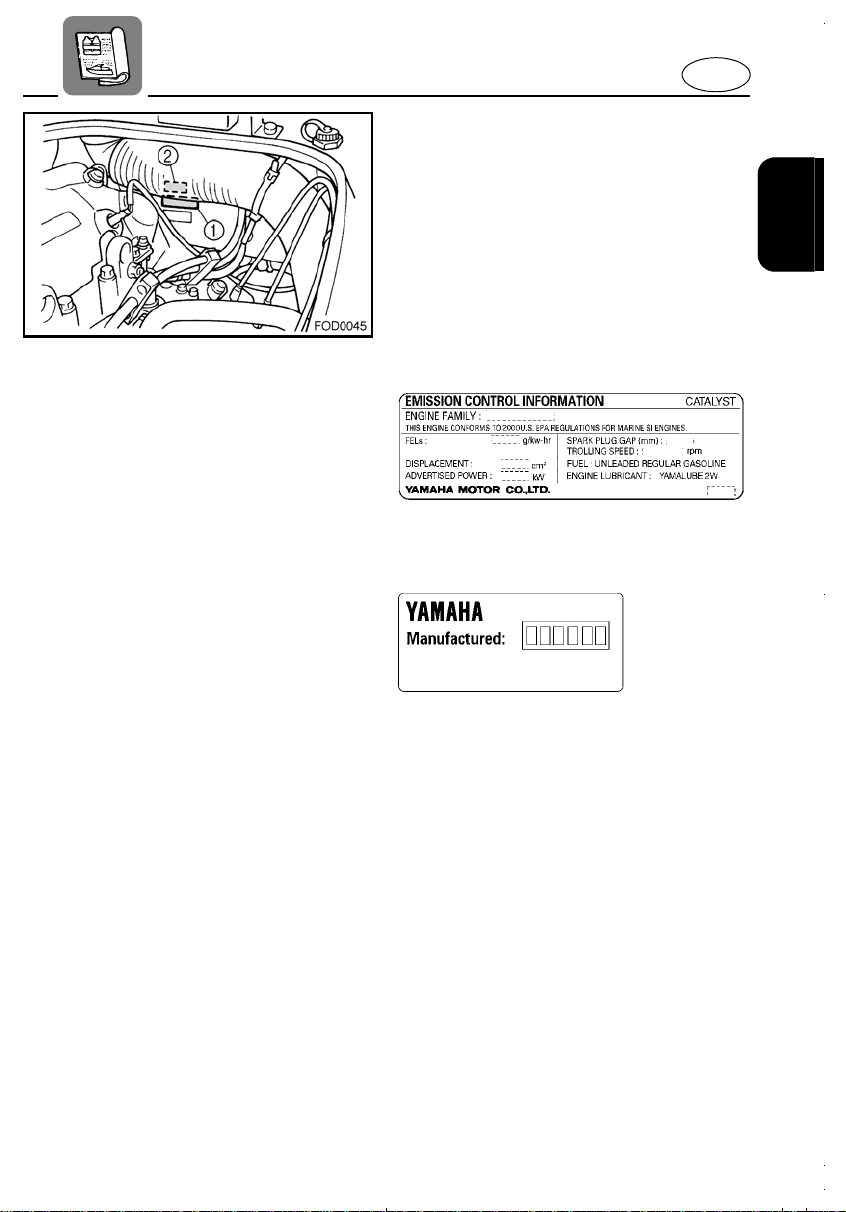
EJU00631a
EMISSION CONTROL
INFORMATION
This engine conforms to 2000 U.S. Environmental Protection Agency (EPA) regulation
for marine SI engines.
● Approved label of Emission control
certificate
This label is attached to the electrical box.
1 Emission control information label
● Manufactured date label
This label is attached to the electrical box.
2 Manufactured date label
1-2
Page 7

EJU00293
LOCATION
E
IMPORTANT LABELS
1-3
Page 8
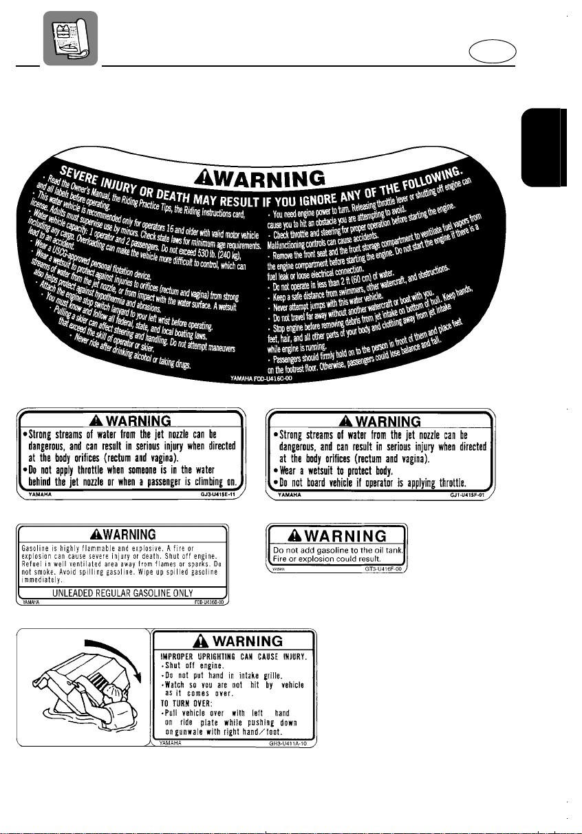
LABELS
Warning labels
1
E
2
3
45
6
1-4
Page 9
E
7
9
@
A
8
B
1-5
Page 10
E
Caution labels
CD
E
F
H
G
I
1-6
Page 11
Other labels
J
E
K
L
1-7
Page 12

E
EJU00640a
SAFETY
INFORMATION
When you operate your water vehicle, you
must know and practice the following for
your safety:
●
Before operating the vehicle, read this
entire manual, the Riding Practice Tips,
the Riding Instruction card and all warning labels on the vehicle. Reading these
materials should give you an understanding of the vehicle and its operation.
Never allow anyone to operate this water
vehicle until they too have read this
owner’s/operator’s manual, the Riding
Practice Tips, the Riding Instruction card
and all warning labels.
●
This product emits exhaust gases which
contain carbon monoxide, a colorless,
odorless gas which may cause brain
damage or death when inhaled. Symptoms include nausea, dizziness, and
drowsiness. Operate the vehicle in an
open area.
EJU00304a
LIMITATIONS ON WHO MAY
OPERATE THE VEHICLE
●
This water vehicle is recommended only
for operators 16 and older with a valid
motor vehicle license.
Even though a motor vehicle operator’s
license is not required for water vehicle
operation in most states, it is one indicator that the operator has previously demonstrated a reasonable degree of
maturity, responsibility, and good judgment.
A responsible adult must supervise operation of this vehicle by minors.
Many states have minimum age and education requirements. Always check states
and all applicable local boating laws that
apply to you before you operate the vehicle.
●
Your water vehicle is designed to carry
the operator and one or two passengers,
as long as the total weight does not
exceed the maximum load capacity.
●
Never exceed the weight capacity nor
allow more than three persons (or two
persons with a skier) to ride this vehicle at
one time.
ATTENTION:
Maximum vehicle load capacity: 240 kg
(530 lb)
Includes weight of operator, passengers,
and any cargo.
●
Do not try to ride with passengers until
you have considerable practice riding
alone. Operating with passengers
requires more skill. Take the time to
become accustomed to the handling
characteristics of the vehicle with passengers before trying any difficult maneuvers.
1-8
Page 13
EJU00613a
CRUISING LIMITATIONS
●
Do not jump boat wakes or follow another
boat or watercraft too closely. You
increase your risk of colliding with another
boat, which could result in severe injury or
death. Do not jump waves, wakes, or any
objects. You risk severe impact injuries.
Jumping can also cause damage to the
vehicle.
●
Do not operate the vehicle in rough water,
bad weather or when visibility is poor; this
may lead to an accident causing injury or
death. Be alert to the possibility of
adverse weather. Take note of weather
forecasts and the prevailing weather conditions before setting out on your water
vehicle.
●
As with any water sport, you should not
ride your water vehicle without someone
else near by. If you ride further than swimming distance from shore, you should be
accompanied by another boat or watercraft. It’s good, common sense!
●
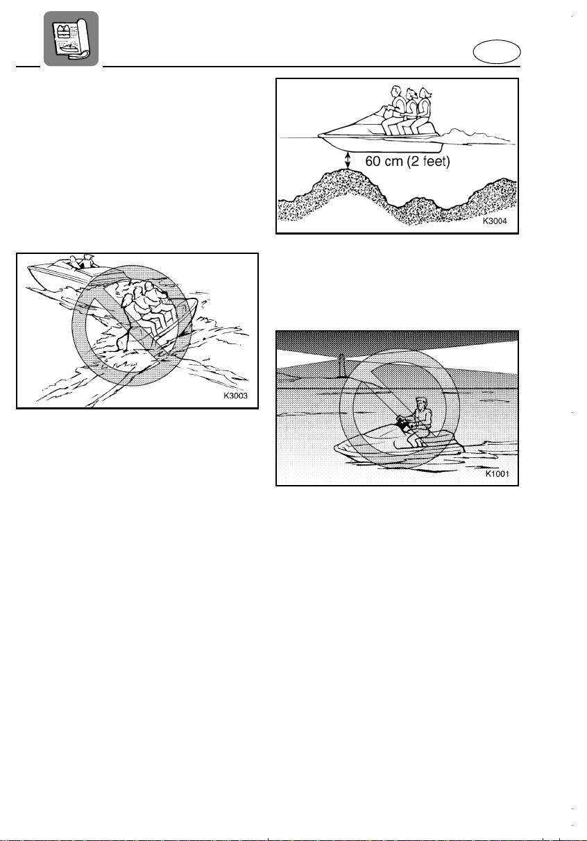
Never ride in w ater that is less than 60 cm
(2 feet) deep. You increase your chance
of hitting an underwater obstacle. You
could be injured.
●
Do not operate the vehicle after sunset or
before dawn. It is not equipped with lighting required for night operation. You risk
collision with another boat which could
cause injury or death.
●
The maximum performance potential of
this watercraft is not suitable for all conditions. Consider water conditions, weather,
boat traffic and other potential obstacles,
speed limits and other local laws, and
your abilities before attempting to travel at
higher speeds. Operate the watercraft no
faster than justified by these conditions.
EJU00618
OPERATIONAL REQUIREMENTS
●
Operating your water vehicle requires
skills acquired only through practice over
a period of time. Take the time to learn the
basic operating techniques well, before
attempting more difficult maneuvers.
E
1-9
Page 14

E
●
Both operator and passengers must
always wear a U.S. Coast Guard
approved personal flotation device (vesttype) because of the drowning hazards
associated with water sports.
1 U.S. Coast Guard-approved personal flotation
device
2 Wet suit
3 Water shoes
4 Gloves
5 Eye protection
Strong streams of water from the jet noz-
●
zle, or impact with the water surface can
be dangerous. Both operator and passengers must wear wet suits. Normal swimming attire may not adequately protect
you. A wet suit will help protect against
internal injuries to orifices (rectum and
vagina) from strong jet streams, and from
impact with the water surface. Wet suits
also help protect against hypothermia
(low body temperature) and abrasions.
Both operator and passengers should
●
wear water shoes to help protect feet from
objects hidden under water. Wearing
gloves can also help protect hands from
abrasions.
Wind, water, and glare from the sun may
●
get in your eyes while you operate your
water vehicle, reducing your ability to see.
You may want to consider wearing eye
protection such as sunglasses or goggles
while riding. Some may find, however,
that eye protection obstructs or distorts
their vision, and distracts from operation.
Only you know the circumstances in
which you operate your water vehicle, so
only you can decide if the benefits of eye
protection outweigh the potential hazards.
If you wear prescription lenses, consider
●
measures to secure them against loss
while riding. For example, some goggles
are designed to be worn over glasses or
contact lenses. Restraining straps for
glasses are also made which are
designed to float if your glasses should
fall in the water.
Helmets meeting Snell or DOT standards
●
are required for IJSBA-sanctioned races.
You must decide whether to wear a helmet while you ride recreationally. A helmet could help protect you in certain
kinds of accidents. You should also know
that a helmet could injure you in some
other riding conditions.
A helmet is designed to provide some
head protection. Although helmets cannot
protect against all foreseeable impacts, a
helmet might reduce your injuries in a collision with a boat or other obstacles.
A helmet may have potential safety hazards, as well. A helmet could catch the
water during a fall into the water. This is
commonly called “bucketing.” The resulting strain on your neck could cause choking, severe and permanent neck injuries,
or death. A helmet could also increase
the risk of an accident if it reduces your
vision or hearing, or if it distracts you or
increases your fatigue.
1-10
Page 15
How should you decide if a helmet’s
potential safety benefits outweigh its
potential risks for you? Consider your particular riding conditions. Consider factors
such as your riding environment and your
riding style and ability. Also consider the
likelihood of traffic congestion, and the
water surface conditions. If you decide to
wear a helmet based upon your riding circumstances, choose one carefully. Look
for a helmet designed for personal watercraft use, if possible. Consider a helmet
meeting Snell or DOT standards. If you
will be engaging in closed-course competition, follow the helmet requirements of
the sanctioning organization.
●
NEVER ride the vehicle after consuming
alcohol or taking drugs.
●
For reasons of safety and proper care,
always perform the pre-operation checks
on page 3-3 before riding.
●
The operator and passengers should
always keep both feet on the footrest floor
when the vehicle is in motion. If you lift
your feet, you increase your chances of
losing your balance, and your feet could
hit objects outside the water vehicle. Do
not give a ride to a child whose feet cannot reach the footrest floor.
Passengers should firmly hold on-either
to the person in front of them or to the
handgrips provided.
●
If you are pregnant or in poor health, ask
your doctor’s advice on whether it is safe
for you to ride this water vehicle.
●
Do not attempt to modify this water vehicle!
Modifications to your machine may
reduce safety and reliability, and may
make the vehicle unsafe or illegal for use.
●
The operator should always attach the
engine stop switch lanyard (cable) to his
left wrist so that the engine will stop if the
operator falls off.
Be sure the lanyard is not wrapped
around the handlebar or tangled in the
controls which would prevent the lanyard
from pulling away.
●
To prevent accidental starting of the
engine, always remove the lock-plate
from the engine stop lanyard switch when
the engine is not running.
1 Engine stop lanyard switch
2 Engine stop switch lanyard
3 Lock-plate
1-11
E
Page 16

E
●
Always watch carefully for swimmers.
Stay away from swimming areas. Swimmers are hard to see and you could accidentally hit someone in the water.
●
Avoid being hit by another boat! You
should always take the responsibility to
watch for traffic, other boaters may not be
watching for you. If they don’t see you, or
you maneuver more quickly than other
boaters expect, you risk a collision.
Maintain a safe distance from other boats
or watercraft, and also watch for boat’ s ski
ropes or fishing lines. Obey the “Rules of
the Road” (see page 1-15~1-18), and be
sure to check behind you before making a
turn.
●
This water vehicle is included in the Class
A inboard boat classification of the U.S.
Coast Guard. A water craft of this type
MUST carry a fire extinguisher of a B-1
classification, with a capacity of two
pounds or more when navigating in
waters under Coast Guard jurisdiction. In
addition, most state and local boating
laws also require that the carry a USCGapproved extinguisher wherever it is operated.
EJU00313a
HAZARD INFORMATION
●
When transporting or storing your water
vehicle, always place the fuel cock in the
“OFF” position. Otherwise, it is possible
for gasoline to overflow from the carburetor.
●
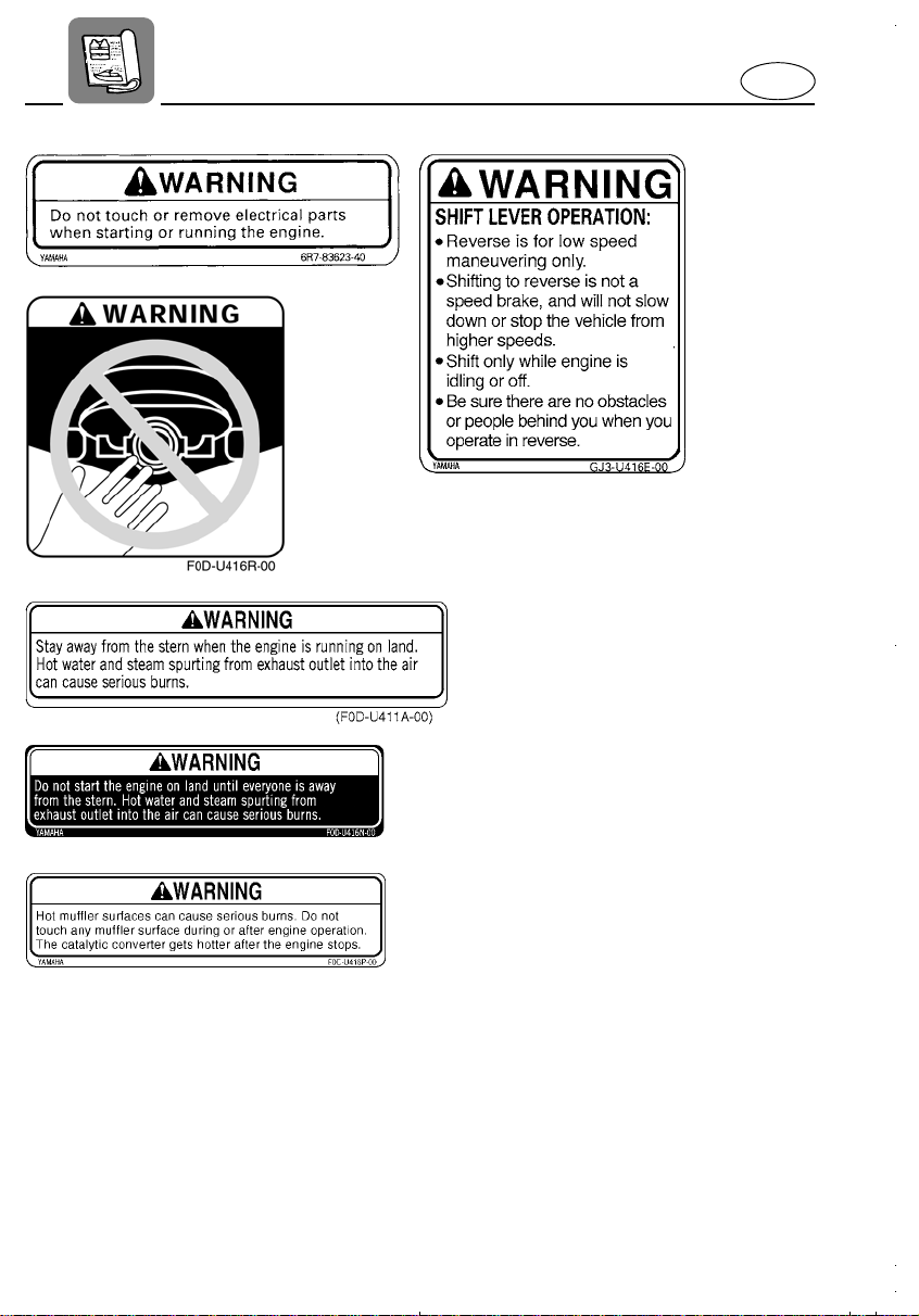
Do not start the engine on land until
everyone is away from the stern. Hot
water and steam spurting from exhaust
outlet into the air can cause serious
burns.
●
Hot muffler surfaces can cause serious
burns. Do not touch any muffler surface
during or after operation. The catalytic
converter gets hotter after the engine
stops.
1-12
Page 17

E
EJU00315a
WATER VEHICLE CHARACTERISTICS
●
Jet thrust turns the vehicle. If you are
going faster than trolling speeds (the lowest maneuvering speed), you must use
throttle to turn. If you release the throttle
completely, you cannot turn-even if you
turn the handlebars. Practice turning in an
open area without obstructions until you
have a good feel for this maneuver.
●
Yamaha water vehicles are water-jet propelled. The jet pump is directly connected
to the engine. This means that jet thrust
will produce some vehicle movement
whenever the engine is running. There is
no “neutral” position. You are either in
“forward” or “reverse,” depending upon
shift lever position.
●
Boats, including your water vehicle, do
not have brakes.
Release the throttle or stop the engine to
slow down. Remember, however, that you
have no steering control without throttle.
Do not expect the “reverse” position to
work as a brake. Shifting to reverse will
not slow down or stop the vehicle from
higher speeds.
●
Keep the following in mind when using
reverse:
Reverse is for launching and low speed
maneuvering only. Shift only when the
engine is idling or off. Do not shift while
applying throttle.
Make sure there are no obstacles or people behind you before shifting into
reverse.
●
Keep hands, feet, hair, and all other parts
of your body and clothing away from jet
intake on the bottom of the hull while
engine is running because they could be
caught in the intake.
Stop the engine and remove the lock
plate from the engine stop lanyard switch
before removing any debris or weeds
which may have collected around the jet
intake.
Never insert any object in the jet pump
outlet. Service injury or death could result
from coming in contact with the rotating
parts of the jet pump.
1-13
Page 18
EJU00655a
WATER SKIING
You can use this water vehicle to pull a
water skier. Keep the following in mind when
using the vehicle for skiing.
●
Because this water vehicle does not have
the size or thrust of a traditional ski boat,
pulling a skier can affect steering and
handling.
●
Your control while pulling a skier is
affected by the skier’s ability, as well as
water and weather conditions.
●
The operator should be comfortable carrying passengers before attempting to
pull a skier.
●
Make gradual turns; sharp turn s require a
high level of skill for both the operator and
skier.
●
Watch for obstacles or other boating traffic which could be hazardous to the skier
as well as you and the vehicle.
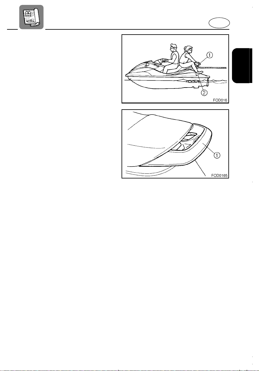
●
When pulling a skier, the observer should
face to the rear while holding the handgrip
with both hands. The observer should
always sit astride the seat with his or her
feet placed firmly on the foot step(s) on
the deck for proper balance.
1 Handgrip
2 Foot step
Towing certain object (such as other
●
boats or watercraft, or heavy or bulky
items) can cause loss of steering control
and create a hazardous condition. If a
suitable object must be towed, ride slowly
and cautiously.
E
1-14
Page 19

E
EJU00319a
RULES OF THE ROAD
Your Y amaha water vehicle is legally considered a power boat. Operation of this
water vehicle must be in accordance with
the rules and regulations governing the
waterway on which it is used.
Just as there are rules which apply when
you are driving on streets and highways,
there are waterway rules which apply when
you are riding your water vehicle. These
rules are used internationa lly, and are also
enforced by the United States Coast Guard
and local agencies. You should be aware of
these rules, and follow them whenever you
encounter another vessel on the water.
Several sets of rules prevail according to
geographic location, but are all basically the
same as the International Rules of the
Road. The rules presented here in your
owner’s/operator’s manual are condensed,
and have been provided for your convenience only. Consult your local U.S. Coast
Guard Auxiliary or Department of Motor
Vehicles for a complete set of rules governing the waters in which you will be riding
your water vehicle.
STEERING AND SAILING RULES
AND SOUND SIGNALS
Whenever two vessels on the water meet
one another, one vessel has the right-ofway; it is called the “stand-on” vessel. The
vessel which does not have the right-of-way
is called the “give-way” or “burdened” vessel. These rules determine which vessel has
the right-of-way, and what each vessel
should do.
Stand-On Vessel
The vessel with the right-of-way has the duty
to continue its course and speed, except to
avoid an immediate collision. When you
maintain your direction and speed, the other
vessel will be able to determine how best to
avoid you.
Give-Way Vessel
The vessel which does not have the right-ofway has the duty to take positive and timely
action to stay out of the way of the Stand-On
vessel. Normally, you should not cross in
front of the vessel with the right-of-way. You
should slow down or change directions
briefly and pass behind the other vessel.
You should always move in such a way that
the operator of the other vessel can see
what you are doing.
WARNING
Do not operate the vehicle after sunset or
before dawn. It is not equi pped wi th lighting required for night operation. You risk
collision with another boat which could
cause injury or death.
“The General Prudential Rule”
This rule is called Rule 2 in the International
Rules and says,
‘In obeying and construing these rules due
regard shall be had to all dangers of navigation and collision, and to any special circumstances, which may render a departure from
the above rules necessary in order to avoid
immediate danger.’
1-15
Page 20
E
In other words, follow the standard rules
except when a collision will occur unless
both vessels try to avoid each other. If that is
the case, both vessels become “Give-Way”
vessels.
RULES WHEN ENCOUNTERING
VESSELS
There are three main situations which you
may encounter with other vessels which
could lead to a collision unless the Steer ing
Rules are followed:
Meeting (you are approaching another vessel head-on)
Crossing (you are trav eling across the other
vessel’s path)
Overtaking (you are passing or being
passed by another vessel)
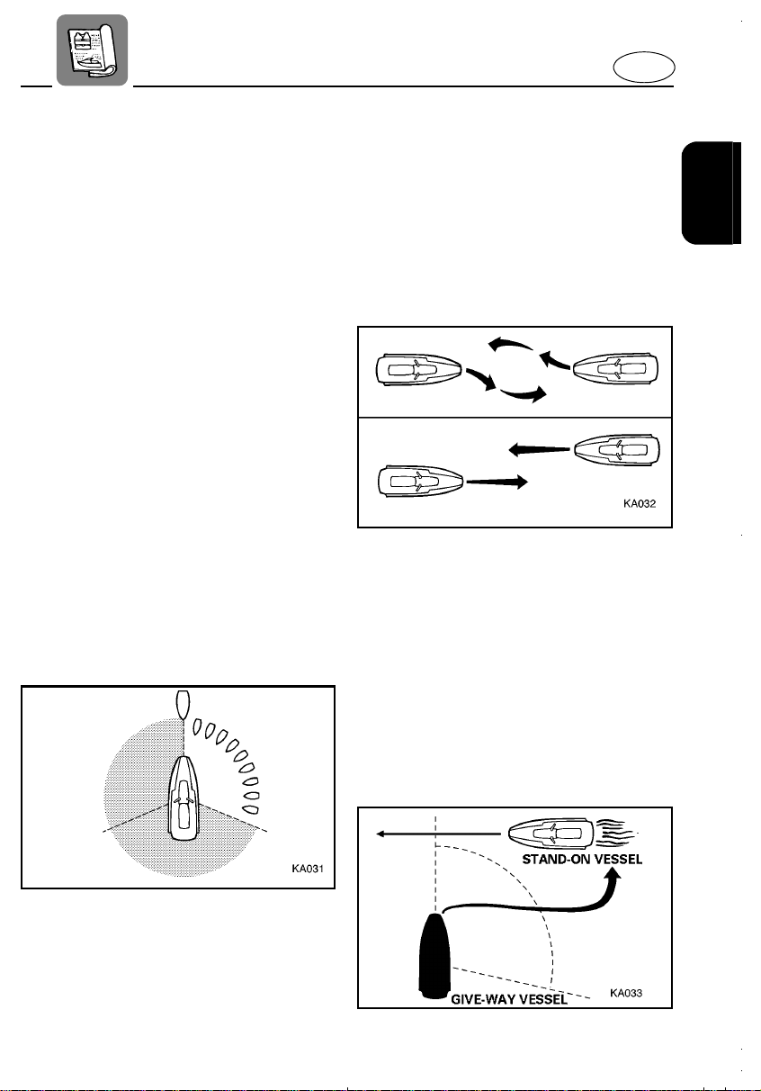
In the following illustration, your water vehicle is in the center. You should give the rightof-way to any vessels shown in the white
area (you are the Give-Way vessel). Any
vessels in the shaded area must yield to you
(they are the Give-Way vessels). Both you
and the meeting vessel must alter course to
avoid each other.
Meeting
If you are meeting another power vessel
head on, and are close enough to run the
risk of collision, neither of you has the r ightof-way! Both of you should alter course to
avoid an accident. You should keep the
other vessel on your port (left) side. This
rule doesn’t apply if both of you will clear
one another if you continue on your set
course and speed.
Crossing
When two power driven vessels are crossing
each other’s path close enough to run the
risk of collision, the vessel which has the
other on the starboard (right) side must keep
out of the way of the other. If the other vessel is on your right, you must keep out of its
way; you are the Give-Way vessel. If the
other vessel is on your port (left) side,
remember that you should maintain course
and direction, provided the other vessel
gives you the right-of-way as it should.
1-16
Page 21

E
Overtaking
If you are passing another vessel, you are
the “Give-Way” vessel. This means that the
other vessel is expected to maintain its
course and speed. You must stay out of its
way until you are clear of it. Likewise, if
another vessel is passing you, you should
maintain your speed and direction so that
the other vessel can steer itself around you.
OTHER SPECIAL SITUATIONS
There are three other rules you should be
aware of when riding your water vehicle
around other vessels.
Narrow Channels and Bends
When navigating in narrow channels, you
should keep to the right when it is safe and
practical to do so. If the operator of a powerdriven vessel is preparing to go around a
bend that may obstruct the view of other
water vessels, the operator should sound a
prolonged blast on the whistle (4 to 6 seconds). If another vessel is around the bend,
it too should sound the whistle. Even if no
reply is heard, however, the vessel should
still proceed around the bend with caution. If
you navigate such waters with your water
vehicle, you will need to carry a portable air
horn, available from local marine supply
stores.
Fishing Vessel Right-of-way
All vessels which are fishing with nets, lines
or trawls are considered to be “fishing vessels” under the International Rules. Vessels
with trolling lines are not considered fishing
vessels. Fishing vessels have the right-ofway regardless of position. Fishing vessels
cannot, however, impede the passage of
other vessels in narrow channels.
Sailing Vessel Right-of-Way
Sailing vessels should normally be given the
right-of-way. The exceptions to this are:
1. When the sailing vessel is overtaking
the power-driven vessel, the powerdriven vessel has the right-of-way.
2. Sailing vessels should keep clear of any
fishing vessel.
3. In a narrow channel, a sailing vessel
should not hamper the safe passage of
a power-driven vessel which can navigate only in such a channel.
Reading Buoys And Other Markers
The waters of the United States are marked
for safe navigation by the lateral system of
buoyage. Simply put, buoys and markers
have an arrangement of shapes, colors,
numbers and lights to show which side of
the buoy a boater should pass on when navigating in a particular direction. The markings on these buoys are oriented from the
perspective of being entered from seaward
(the boater is going towards the port). This
means that red buoys are passed on the
starboard (right) side when proceeding from
open water into port, and black buoys are to
port (left) side. When navigating out of port,
your position with respect to the buoys
should be reversed; red buoys should be to
port and black buoys to starboard.
Many bodies of water used by boaters are
entirely within the boundaries of a par ticular
state. The Uniform State Waterway Marking
System has been devised for these waters.
1-17
Page 22

E
This system uses buoys and signs with distinctive shapes and colors to show regulatory or advisory information. Th ese markers
are white with black letters and orange
boarders. They signify speed zones,
restricted areas, danger areas, and general
information.
Remember, markings may vary by geographic location. Always consult local boating authorities before riding your water
vehicle in unfamiliar waters.
1-18
Page 23

E
EJU00320a
TO GET MORE BOATING
SAFETY INFORMATION
Be informed about boating safety. Additional
publications and information can be
obtained from many organizations, including
the following.
United States Coast Guard
Consumer Affairs Staff (G-BC)
Office of Boating, Public, and Consumer
Affairs
U.S. Coast Guard Headquarters
Washington, D.C. 20593-0001
Boating Safety Hotline: 1-800-368-5647
Personal Watercraft Industry Association
(PWIA)
401 N. Michigan Ave.
Chicago, IL 60611
Personal Watercraft Riders Association
(PWRA)
401 N. Michigan Ave.
Chicago, IL 60611
EJU00322a
ENJOY YOUR WATER
VEHICLE RESPONSIBLY
●
You share the areas you enjoy when
riding your water vehicle with others and
with nature. So your enjoyment includes a
responsibility to treat these other people
and nature with respect and courtesy.
●
Whenever and wherever you ride, think of
yourself as the guest of those around you.
Remember, for e xample, that the sound of
your water vehicle may be music to you,
but it could be just noise to others. And
the exciting splash of your wake can
make waves others won’t enjoy. Avoid
riding close to shoreline homes and
waterfowl nesting areas or other wildlife
areas, and keep a respectful distance
from fishermen, other boats, swimmers,
and populated beaches. When travel in
areas like these is unavoidable, ride
slowly and obey all laws.
●
Remember that pollution can be har mful
to the environment. Do not refuel or add
oil where a spill could cause damage to
nature. Remove your water vehicle from
the water and move it away from the
shoreline before refueling. Keep your surroundings pleasant for the people and
wildlife that share the waterways: do not
litter!
●
When you ride responsibly, with respect
and courtesy for others, you help ensure
that our waterways stay open for the
enjoyment of a variety of recreational
opportunities.
1-19
Page 24

EJU00323a
:
FUEL REQUIREMENTS
GASOLINE (PETROL)
WARNING
GASOLINE (PETROL) AND ITS VAPORS
ARE HIGHLY FLAMMABLE AND EXPLOSIVE!
● Do not smoke when refueling, and
keep away from sparks, flames, or
other sources of ignition.
● Stop the engine before refueling.
● Refuel in a well-ventilated area. Do not
stand or sit on the vehicle while refueling in case of fire.
● Take care not to spill gasoline (petrol).
If gasoline (petrol) spills, wipe it up
immediately with dry rags. Always
properly dispose of gasoline-soaked
rags.
● Avoid overfilling the fuel tank. Stop fill-
ing when the fuel level just reaches the
bottom of the filler tube. Do not fill up
the filler tube because fuel expands as
it warms up and could overflow.
● Tighten the filler cap securely after
refueling.
● If you should swallow some gasoline
(petrol), inhale a lot of gasoline (petrol)
vapor, or get gasoline (petrol) in your
eyes, get immediate medical attention.
● If any gasoline (petrol) spills onto your
skin, immediately wash with soap and
water. Change clothing if gasoline
(petrol) spills on it.
E
Recommended gasoline:
Unleaded regular gasoline with a
minimum octane rating of:
86 (Pump octane number)=(R+M)/2
90 (Research octane number)
Gasohol
There are two types of gasohol: gasohol
containing ethanol and that containing methanol. Gasohol containing ethanol can be
used if ethanol content does not exceed
10% and the fuel meets minimum octane
ratings. Gasohol containing methanol is not
recommended by Yamaha because it can
cause fuel system damage or engine performance problems.
EJU00654a
ENGINE OIL
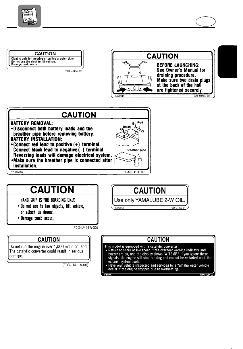
CAUTION
Use only YAMALUBE 2-W oil. Using
another oil can seriously damage the catalytic converter and other engine components.
Recommended engine oil:
YAMALUBE 2-W oil only
NOTE:
YAMALUBE 2-W is developed for this water
vehicle and available from a Yamaha water
vehicle dealer.
CAUTION:
● Do not use leaded gasoline. Leaded
gasoline can seriously damage the
catalytic converter.
● Use only fresh gasoline (petrol) that
has been stored in clean containers.
1-20
Page 25

– MEMO –
E
Page 26
EJU00326
Chapter 2
FEATURES AND
FUNCTIONS
E
LOCATION OF MAIN COMPONENTS
OPERATION OF CONTROLS AND
OTHER FUNCTIONS
Front seat...........................................2-5
Rear seat............................................2-5
Front hood..........................................2-6
Fuel and oil tank filler caps.................2-7
Fuel cock............................................2-7
Engine stop switch.............................2-8
Engine stop lanyard switch ................2-8
Choke knob........................................2-8
Throttle lever......................................2-9
Starter switch .....................................2 -9
Cooling water pilot outlet..................2-10
Steering............................................2-10
Tilt handle lever................................2-11
Shift lever.........................................2-12
Quick shift trim system(Q.S.T.S.).....2-13
Overheat warning system ................2-15
Exhaust temperature warning
system..............................................2-16
Handgrip...........................................2-17
Bow eye, rope holes, and cleat........2-17
Multifunction meter...........................2-18
Storage compartments.....................2-28
.............................2-5
.2-1
2
Page 27

EJU00327
E
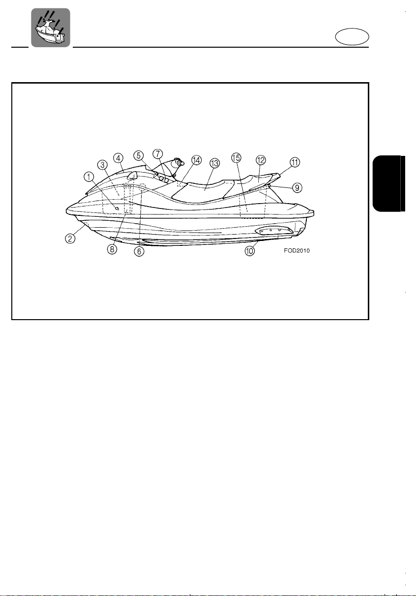
LOCATION OF MAIN COMPONENTS
1 Handlebars
Control steering direction
2 Fuel tank filler cap
Unscrew counterclockwise to add fuel
Tighten securely clockwise
3 Rope hole
Rope attachment point for transporting,
mooring
4 Footrest floor
To place feet for balance
5 Foot steps
To be used by the observer as a footrest when
pulling a water skier
6 Front seat latch
7 Rear seat latch
Locking and releasing the seat rock
8 Intake grille
Prevents debris from getting into the jet pump
9 Speed sensor
2-1
Page 28
E
1 Cooling water pilot outlet
Check point of cooling water flowing
2 Bow eye
Rope attachment point for transporting,
mooring or towing the water vehicle in an
emergency
3 Front storage compartment
4 Front hood
5 Fuel cock
Select fuel flow from normal or reserve area of
the fuel tank, or shut off fuel flow
6 Oil tank filler cap
Unscrew counterclockwise to add oil
Tighten securely clockwise
7 Choke Knob
Pull knob when starting a cold engine
8 Fire extinguisher container
9 Cleat
Rope attachment point for pulling a water skier
0 Jet intake (Water intake)
Water inlet for jet stream
A Hand grip
B Rear seat
C Front seat
D Glove compartment
E Seat storage compartment
2-2
Page 29
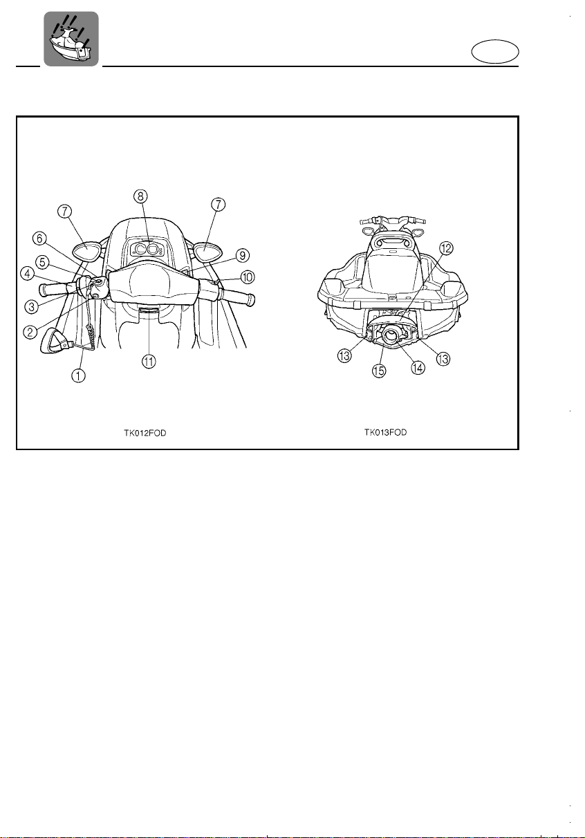
E
1 Engine stop switch lanyard (Cable)
By connecting to the engine stop lanyard
switch and operator will stop the engine If the
operator falls off the vehicle
2 Engine stop switch
Depress to stop the engine
3 Lock-plate
Insert the lock-plate in the engine stop lanyard
switch to allow the engine to be started
Remove the lock-plate to stop the engine or
prevent it from starting
4 QSTS (Quick Shift Trim System) controller
Controls thrust trim for different operating conditions
5 Engine stop lanyard switch
Removing the lock-plate makes to stop the
engine and disable to start the engine
6 Starter switch
Depress to start the engine
7 Adjustable mirrors
8 Multi function meter
Shows vehicle speed, engine speed and some
other conditions on the vehicle
9 Shift lever (F-R)
Selects “Forward” or “Reverse” of the vehicle
0 Throttle lever
Controls the engine speed when accelerating
and decelerate
A Tilt handle lever
Adjusts the tilt position of the handlebar’s boss
B Reverse gate
Controls direction of thrust for reversing
C Drain plugs
Open to drain water in the bilge when the vehicle is on land. Tighten securely before launching craft
D Jet nozzle
Changes the direction of jet thrust according
to handlebar position to steer the vehicle
E Jet pump cover
2-3
Page 30

E
1 Spark plug / spark plug cap
2 Electrical box
Contains most electrical components in this
water resistant box
3 Flush hose connector
To flush the engine cooling water passages
4 High tension cord
Deliver electrical current to the spark plug
5 Muffler box
6 Fuel filter
Prevents dust contained in fuel from getting
into the carburetor
7 Fuel tank
8 Oil tank
9 Battery
2-4
Page 31

E
EJU00328
OPERATION OF CONTROLS
AND OTHER FUNCTIONS
EJU00714
FRONT SEAT
There is a seat latch lever 1 at the rear of
the seat to remove the front seat.
Removal
Pull the front seat latch lever up, then lift the
rear of the seat, and pull back.
Installation
Position the seat on the deck so the front
projections on the underside of the seat fits
into the stays on the deck. Then push the
rear of the seat down until the seat locks
latch securely.
NOTE:
The front seat can be removed after removing the rear seat.
EJU00335a
REAR SEAT
There is a seat latch lever 1 at the rear of
the seat to remove the rear seat.
Removal
Pull the rear seat latch lever up, then lift the
rear of the seat and pull back.
2-5
Page 32

E
Installation
Position the seat on the deck so the front
projections on the underside of the seat fits
into the stays on the deck. Then push the
rear of the seat down until the seat locks
latch securely.
EJU00703
FRONT HOOD
The front hood is secured at the rear by one
latch. Pull the latch lever 1 up and lift the
hood, to open it.
NOTE:
Make sure the front hood is firmly secured
with the latch before riding.
2-6
Page 33

E
EJU00347
FUEL AND OIL TANK FILLER CAPS
To remove the fuel or oil tank filler cap, turn
it counterclockwise.
1 Fuel tank filler cap
2 Oil tank filler cap
Be sure to tighten the caps securely before
riding.
EJU00704
FUEL COCK
The fuel cock 1 supplies fuel from the fuel
tank to the carburetor.
The fuel cock has three positions;
OFF
With the knob in this position, fuel does not
flow. Always turn the knob to this position
when the engine is not running.
ON
With the knob in this position, fuel flows to
the carburetor. Normal running is done with
the knob in this position.
RES
If you run out of fuel in the
turn the knob to this position to be able to
continue for a short time.
Remember to FILL THE TANK AT THE
FIRST OPPORTUNITY.
After refueling, return the fuel cock knob to
the
position for further riding.
“ON”
“ON”
position,
2-7
Page 34

E
EJU00705
ENGINE STOP SWITCH
The engine can be stopped normally by
pressing the red button 1.
EJU00706a
ENGINE STOP LANYARD SWITCH
The engine can be also stopped if you fall
off, or in case of an emergency, when the
lock plate 1 attached to the lanyard 2 is
pulled out from the engine stop lanyard
switch 3.
Should the lock-plate be removed for any
reason, the engine stops by itself.
EWJ00048
WARNING
●
Always attach the engine stop switch
lanyard (cable) to your left wrist
BEFORE starting the engine.
●
To prevent accidental starting of the
engine, always remove the lock-plate
from the engine stop lanyard switch
when the engine is not running.
NOTE:
When the red button on the engine stop
switch is pushed, without removing the lockplate from the engine stop lanyard s w itch, the
ignition circuit opens and stops the engine.
EJU00350a
CHOKE KNOB
Pulling this knob 1 supplies a rich air/fuel
mixture required to start a cold engine.
NOTE:
Refer to the “Starting the engine” se ction for
proper operation.
2-8
Page 35

E
EJU00707
THROTTLE LEVER
Moving the throttle lever 1 toward the handlebar increases engine speed. When the
throttle lever is released, it returns to its
closed (idle) position through the action of a
return spring.
EWJ00049
WARNING
Before starting the engine, always check
the operation of the throttle lever. It
should move smoothly through its full
range of operation, and should spring
back to the idle position when released.
EJU00708
STARTER SWITCH
You can start the engine by pushing the
green button 1.
NOTE:
● The engine will not start when the lock
plate is removed from the engine stop lanyard switch. The starter motor will not
turn.
● The engine will not start if the “LOCK”
mode has been chosen. To set the mode
to “START”, refer to the “PADLOC” function in the “MULTIFUNCTION METER”
instructions.
2-9
Page 36

E
EJU00709
COOLING WATER PILOT OUTLET
This engine is equipped with a cooling-water
pilot outlet at both sides of the deck. Check
that water comes out of the outlet while the
engine is running. If you do not see any
water at the outlet, cooling water may not be
circulating in the engine.
In that case, stop the engine and check for
the cause (Refer to overheat warning system).
NOTE:
If water cooling passages on the engine are
dry it will take about 20 seconds to reach
water at the outlet after starting.
EJU00356a
STEERING
Your water vehicle can be steered by turning
the handlebar 1 the same direction you
wish to travel, to the right or left. When the
handlebar is turned, the angle of the jet (output) nozzle at the stern is changed, and the
change in direction of the nozzle changes
the direction of the vehicle accordingly.
Therefore, because only the strength of the
jet-flow output can determine the speed and
direction of a turn, the throttle must always
be opened above idle when attempting a
turn, except at trolling speed.
2-10
Page 37

E
EJU00670
TILT HANDLE LEVER
Tilt handle lever 1 is located in front of the
glove compartment to adjust the tilt position
of the handle.
Adjusting the handle position
1) Pull up the tilt handle lever.
2) Move the handle up or down in an
appropriate position you desire.
3) Push the lever and put force on the handle up and down to make sure that it is
securely fastened.
WARNING
● Never touch the tilt handle lever during
operation. Otherwise, the handle may
suddenly be changed in position, leading to an unexpected accident.
● Make sure secure the tilt handle lever
after adjusting the handle position. If
the handle is insecurely fastened, it
may be suddenly changed in position
with the resultant unexpected accident.
2-11
Page 38

E
EJU00710
SHIFT LEVER
This water vehicle is equipped with a shift
lever. By placing the shift lever in “Forward”
or “Reverse”, the direction of the jet thrust
can be changed. Use “Reverse” for slowspeed maneuvering only. It is useful when
launching the vehicle from a trailer, or when
it is necessary to back up out of tight spots
where you cannot turn around.
To shift in Reverse, close the throttle and
pull the shift lever up using your right hand.
EWJ00050
WARNING
● Make sure there are no obstacles or
people behind you before shifting into
reverse.
● Do not touch the reverse gate while it
is being shifted. You could be pinched.
EWJ00050
2-12
Page 39

E
:
EJU00360a
QUICK SHIFT TRIM SYSTEM(Q.S.T.S.)
The trim angle of your water vehicle can be
adjusted by operating the Q.S.T.S.
Operating the trim shifting grip 1 changes
the angle of the jet (output) nozzle at the
stern. The nozzle angle changes the trim
angle of the vehicle to one of five positions.
NOTE:
There are two positions A and B for bow
down, neutral “N”, and two positions C and
D for bow up.
Changing the trim angle of the vehicle
1) Set the throttle lever to half open (3,000
r/min) or less.
2) Squeeze and hold the shift lock release
lever 2. Then turn the trim shifting grip
to the desired position.
● Turning the grip to A or B from “N”:
Bow will go down while the vehicle is
on plane.
● Turning the grip to C or D from “N”:
Bow will go up while the vehicle is on
plane.
3) Release the shift lock release lever to
lock the position.
ECJ00049
CAUTION
Do not turn the grip while operating the
vehicle at full throttle, otherwise damage
could occur to the Q.S.T.S.
The Neutral (“N”) shift position will provide
good performance for most conditions. To
enhance particular types of performance,
choose the one of the “Bow Down” or “Bow
Up” positions.
2-13
Page 40

E
Shifting to “Bow Down”
“Bow Down” puts more of the bow in the
water. This gives the water vehicle more
“hook,” which enhances turning performance. This position will also help the water
vehicle get up on plane more quickly. At
higher speeds, however, the water vehicle
will have greater tendency to “bow steer”
and follow waves and wakes in the water.
Fuel economy and maximum speed are also
reduced.
Shifting to “Bow Up”
“Bow Up” puts less of the bow in the water.
There is less water resistance, so straightahead acceleration when on plane and top
speed are enhanced. In some conditions,
however, the vehicle may tend to “porpoise”
(hop in the water). If the vehicle is porpoising, choose Neutral or Bow Down trim.
2-14
Page 41

E
:
EJU00696a
OVERHEAT WARNING SYSTEM
The engine has an overheat warning device. If
the engine starts to overheat, the warning
lamp(LED), indicator and “W.TEMP” on the
meter begin to blink and the buzzer sounds
intermittently . If this happens, re duce the engine
speed and return to beach at low speed. If
there is no water discharge at the cool ing w ater
pilot outlet while the engine is running, check
the jet intake and impeller fo r clogging.
EWJ00051a
WARNING
Before attempting to remove weeds or
debris from the jet intake or impeller
areas, shut off the engine and remove
the engine stop switch lock-plate from
the stop switch. Severe injury or death
could result from coming in contact with
the rotating parts of the jet pump.
CAUTION
This model is equipped with a catalytic
converter.
● Return to shore at low speed if the over-
heat warning indicator and buzzer are
on, and the display shows “W.TEMP.” If
you ignore these signals, the engine will
stop running and cannot be restarted
until the exhaust system cools.
● Have your vehicle inspected and ser-
viced by a Yamaha water vehicle dealer if
the engine stopped due to overheating.
2-15
Page 42

E
If the initial overheat warning is ignored,
engine and exhaust system heat can
increase, particularly if the vehicle continues
to be operated at higher speed. If so, the
warning indicators and buzzer will change
from intermittent to constantly on and the
overheat system will stop ignition to the
engine to reduce the risk of severe overheating. The engine cannot be restarted until it
cools down, so it may be necessary to have
the vehicle towed back to the beach. Refer to
“Towing the Water Vehicle” on page 5-6.
NOTE:
●
The buzzer stops sounding if any button
on the meter is pressed.
●
Ask a Yamaha water vehicle dealer to
inspect the vehicle if there is no apparent
reason for overheating.
EJU00697a
EXHAUST TEMPERATURE WARNING SYSTEM
This engine has an exhaust temperature
warning device. If the exhaust temperature
gets too hot, the warning lamp(LED) will
blink, and the indicator and “EXHST” will
light. The buzzer also sounds intermittently.
If this happens, reduce engine speed and
return to the beach at low speed. Allow the
exhaust system to cool.
WARNING
Hot muffler surfaces can cause serious
burns. Do not touch any muffler surface
during or after engine operation. The catalytic converter gets hotter after the
engine stops.
2-16
Page 43

E
:
:
:
CAUTION
This model is equipped with a catalytic
converter. Return to shore at low speed
(below 4000 r/min) if the warning indicator and buzzer are on, and the display
shows “EXHST.” Have your vehicle
inspected and serviced by a Yamaha
water vehicle dealer if the engine
stopped due to overheating.
NOTE:
●
The buzzer stops sounding if any button
on the meter is pressed.
●
Ask a Yamaha water vehicle dealer to
inspect the vehicle if there is no apparent
reason for overheating.
EJU00367a
HANDGRIP
Handgrip 1 provide a handhold to use while
boarding the vehicle.
ECJ00051
CAUTION
Do not use to tow objects, lift vehicle, or
attach tie downs. Damage could occur.
EJU00368a
BOW EYE, ROPE HOLES, AND C LEAT
The bow eye 1, rope holes 2, and cleat 3
are designed for mooring the vehicle and for
securing it to the trailer.
ECJ00052a
CAUTION
Do not use the bow eye, rope holes and
cleat to lift the vehicle. Damage could
occur.
2-17
Page 44

E
:
EJU00698
MULTIFUNCTION METER
This meter contains following functions for
the help and convenience of operation.
1 “MODE” button
2 “SET” button
3 “CODE” setting buttons
4 Tachometer
5 Speedometer
6 Fuel meter
7 Engine oil meter
8 Display for Clock, Hour meter, Tr ip meter and
Trip timer
9 Warning lamp(LED)
0 Display for PADLOC and direction of warning
indicator
A Battery warning indicator
B Exhaust temperature warning indicator
C Overheat warning indicator
D Fuel warning indicator
E Oil warning indicator
CAUTION
● Do not run the engine over 4,000 r/min
to check the meter for operation on
land. The engine could overheat or the
catalytic converter could result in serious damage.
● Use the specified resistor-type spark
plug and cap, otherwise the meter may
function erratically.
NOTE:
The demonstration mode display starts
showing after the engine starts, then all d isplay light up and the buzzer sounds twice.
The meter will operate normally after few
seconds. The current display will continue to
operate for 30 seconds after the engine
stops.
2-18
Page 45

E
EJU00711a
PADLOC (Programmable digital locking
ignition)
This feature is provided to deter unauthorized use. The function allows you to chose
either “START” or “LOCK” mode, as the situation requires, much as you would use a
main switch key in a motor vehicle. If you
have previously chosen “LOCK” mode, the
engine will not start unless the right code is
put in to select “START” mode.
NOTE:
If you do not use the PADLOC system, it is
unnecessary to perform the initial setting of
the PADLOC. If so, the “START” mode is
automatically selected.
● Initial setting
1) Disconnect the blue connector 1
behind the front storage compartment.
2) After the warning lamp(LED) lights,
press the “MODE” button for at least 3
seconds until the display shows “COdE”.
You are ready to set your code.
2-19
Page 46

E
3) Select your 4-letter code b y pressing the
“A/SET”, “B” or “C” buttons in a desired
sequence.
NOTE:
If you do not press a button f or more than 10
seconds, the display automatically turns off.
This cancels the process of setting of a
code.
4) After completing code setting, the
buzzer will sound 3 times and the display will show “SET”. Lastly, the display
turns off and the warning lamp (LED)
turns on again. After the meter has displayed this sequence, reconnect the
blue connector.
NOTE:
●
Your own code is kept even if the battery
terminal is disconnected.
●
If you forget your own code, or if you want
to change the code, do this “Initial setting”
procedure again from the beginning.
● Selecting “START” or “LOCK” mode
Selecting the desired mode can only be
done after the “Initial setting” has been done
and while the display is not lighting.
1) Press the “MODE” button until the meter
displays the current mode, “START” or
“LOCK”.
2) With “START” or “LOCK” displayed,
press the “MODE” button continuously
for about 3 seconds until the display
changes to “COdE”.
2-20
Page 47

E
3) Enter your 4-letter code by pressing the
“A/SET”, “B” or “C” buttons in the right
sequence.
NOTE:
If you do not press a button f or more than 10
seconds, the display automatically turns off.
This cancels the process of selecting the
mode.
4) If the code entered is correct, the mode
will change from the previous mode to
either “START” or “LOCK”. Then the
mode display and buzzer will operate for
2 seconds.
NOTE:
●
Once you select a mode, the mode will
not be changed unless you perform this
mode selection again.
●
If the wrong code has been put in, the
mode display shows “ERROR” for 2 seconds and the buzzer will sound 5 times.
Then the display turns back to “COdE”.
EJU00383
Tachometer
The engine speed (r/min) is display ed b y segments. Each segment indicates a 200 r/min
increment.
2-21
Page 48

E
EJU00384
Speedometer
The meter shows the vehicle speed in miles
per hour (mph).
EJU00386a
Fuel meter
The fuel meter is provided for convenient
fuel level checking while riding. The fuel
meter has four segments which show the
amount of fuel remaining in the fuel tank.
NOTE:
The indication of the segments differs on
your operating condition. Use the meter as a
reference.
2-22
Page 49

E
EJU00387a
Engine oil meter
The engine oil meter is provided for convenient oil level checking while riding. The
engine oil meter has three segments whi ch
show the amount of oil remaining in the oil
tank.
NOTE:
The indication of the segments differs on
your operating condition. Use the meter as a
reference.
EJU00388a
Clock
A 12-hour clock is provided in this meter. To
show the clock, press the “MODE” button
until the display shows “CLOCK”.
● Setting the time
1) When the display shows “CLOCK”,
press the mode button for at least three
seconds.
2) The buzzer will sound once. The display
of hour unit and “SET” start blinking.
Then press the “A/SET” button until
desired hour is displayed.
3) Press “MODE” button again.
4) The buzzer will sound once. The display
of minute unit and “SET” start blinking.
Then press the “A/SET” button until
desired minute is displayed.
5) Press “MODE” button again.
2-23
Page 50

E
6) The buzzer will sound twice. The warning lamp (LED) and “SET” blinks for two
seconds. Then the display turns to
“CLOCK” and shows the time.
NOTE:
After the battery terminal is disconnected,
the clock will be reset to 12:00.
EJU00390
Hour meter
The hour meter is provided to make it easy
to follow the maintenance schedule. The
meter shows the hours of engine operation
that have elapsed since the vehicle was
new. To show the hour meter, press the
“MODE” button until the display shows
“HOUR.M”.
EJU00659a
Trip timer
The trip timer is provided for counting the
time traveled on a given trip . To show the trip
timer, press the “MODE” button until the display shows “TRIP.T”.
1 Minute unit
2 Second unit
● Operation
1) When the display shows “TRIP.T”, press
the “A/SET” button to start counting.
The buzzer will sound once.
2) Press the “A/SET” button again to stop
counting. The buzzer will sound once.
3) Press “MODE” button for at least two
seconds to reset the counted time.
The buzzer will sound twice. The display
of time and “TRIP.T” blinks for two seconds. Now it is ready to start counting.
2-24
Page 51

E
EJU00712
Trip meter
A trip meter is provided for measuring the
approximate traveled distance in miles. To
show the trip meter, press the “MODE” button until the display shows “TRIP”. After
showing “TRIP”, the display turns to “MILE”.
1) When the display shows “.MILE”, press
the “MODE” button for at least 2 seconds.
2) The buzzer will sound twice. The warning lamp(LED) and “.MILE” blink for 2
seconds, and “000” is displayed. Now
the meter will start to measure the distance you will tr avel.
3) When the trip meter begins measuring
the traveled distance, the “.” to the left of
“MILE” on the display will blink.
NOTE:
Measured distance may vary depending on
the water surface conditions, and wind
direction. The measured distance should be
used for a reference.
EJU00716
Fuel warning indicator
If the fuel remaining in the tank drops to
about 17 L (4.5 US gal, 3.7 Imp gal), the fuel
level segment, the fuel warning indicator,
“FUEL” and the warning lamp(LED) begin to
blink. The buzzer also starts sounding intermittently.
2-25
Page 52

E
EJU00717
Oil warning indicator
If the oil remaining in the tank drops to about
1.4 L (0.37 US gal, 0.31 Imp gal) or the oil
filter is clogged, the oil level segment, the oil
warning indicator, “OIL” and the warning
lamp(LED) begin to blink. The buzzer also
starts sounding intermittently.
If the oil warning indicator begins to blink,
refill with engine oil as soon as possible.
NOTE:
If the warning indicator blinks with adequate
oil in the tank, check the oil filter for clogging.
EJU00718a
Overheat warning indicator
If the engine starts to overheat, the overheat
warning indicator, “W.TEMP” and the warning lamp(LED) begin to blink. The buzzer
also starts sounding intermittently.
If the engine continues to be operated at
higher speed after the warning system indicators have come on intermittently, the
warning indicator, “W.TEMP” and the warning lamp(LED) will change to being on continuously. Also, the engine will stop and the
buzzer will sound continuously. Refer to
“Overheat Warning System” on page 2-15.
NOTE:
When the warnings overlap each other, their
priority is as follows.
1. Final overheat
2. Exhaust temperature
3. Initial overheat
4. Oil
5. Fuel
6. Battery
2-26
Page 53

E
EJU00720a
Exhaust temperature warning indicator
If the exhaust system becomes too hot, the
exhaust temperature warning indicator will
come on. Also, the warning lamp (LED) will
blink and the buzzer will start sounding intermittently. Refer to “Exhaust temperature
warning system” on page 2-16.
EJU00719
Battery warning indicator
If the battery voltage becomes less than
11.5 volts, the battery warning indicator,
“VOLT” and the warning lamp(LED) begin to
blink. The buzzer also starts sounding.
If this happens during operation, beach the
vehicle. Then recharge the battery and have
the charging system inspected by a Yamaha
water vehicle dealer.
2-27
Page 54

E
EJU00721a
STORAGE COMPARTMENTS
The storage compartment(s) is provided to
store the manuals, tools, and other equipment for cruising.
Make sure all storage compartments are
firmly secured before riding.
NOTE:
The storage compartment(s) is not designed
to be waterproof. If you put the manuals in
the compartment(s), store them in a waterproof bag to protect them from water damage.
If your owner’s manual becomes damaged,
order a replacement from a Yamaha water
vehicle dealer.
Front storage compartment
A front storage compartment is provided
under the front hood.
Pull up the hood lock lever 1 to open the
front hood.
NOTE:
● Front storage compartment 2
Capacity: 56 L (15 US gal, 12 Imp gal)
Load limit: 5 kg (11 lb)
● The front storage compartment can be
removed to access the engine room.
Push down the rear of the front hood until it
locks securely.
2-28
Page 55

E
Grove compartment
A grove compartment is provided below the
handle bars. Slide the latch 3 to open the
compartment. To close the lid, push it down
until it locks securely.
NOTE:
Grove compartment 4
Capacity: 1.7 L (0.45 US gal, 0.37 Imp gal)
Load limit: 1 kg (2.2 lb)
Seat storage compartment
A seat storage compartment is provided
under the rear seat.
Refer to “REAR SEAT” for removal and
installation.
NOTE:
Seat storage compartment 5
Capacity: 30 L (8 US gal, 6.6 Imp gal)
Load limit: 9 kg (19.8 lb)
2-29
Page 56

EJU00410
Chapter 3
OPERATION AND
RIDING
E
GASOLINE (PETROL) AND ENGINE
OIL FILLING
Filling the gasoline (petrol) tank .........3-1
Filling the oil tank ...............................3-2
PRE-OPERATION CHECKS
Check point........................................3-4
OPERATION
Break-in (running-in) procedure .......3-10
Starting the engine...........................3-12
Stopping the engine.........................3-15
RIDING YOUR WATER VEHICLE
Getting to know your water vehicle..3-16
Learning to ride your water vehicle..3-16
Riding with passengers....................3-17
Starting.............................................3-18
Boarding and starting in deep water 3-19
Load limit..........................................3-21
Capsized water vehicle....................3-22
Turning.............................................3-23
Stopping...........................................3-24
Beaching..........................................3-25
Docking............................................3-25
Launching.........................................3-26
Reverse (on waterways) ..................3-26
Rough water operation.....................3-26
..........................................3-1
.................3-3
........................................3-10
......3-16
3
POST-OPERATION CHECKS
Transportation..................................3-29
.............3-27
Page 57

E
:
EJU00411
GASOLINE (PETROL) AND
ENGINE OIL FILLING
This engine uses Yamaha’s oil injection system, which provides superior lubrication by
ensuring the proper oil ratio for all operating
conditions. No fuel premixing is necessary
(except during break-in / running-in). Simply
pour gasoline (petrol) into the fuel tank and
oil into the oil tank.
EJU00722
FILLING THE GASOLINE (PETROL)
TANK
1) Open the front hood and remove the
front storage compartment, to check the
fuel level.
2) Remove the fuel tank filler cap, and
slowly add fuel to the fuel tank. Be careful not to spill fuel or overfill the tank.
3) Stop filling when the fuel just reaches
the bottom of the filler tube on the fuel
tank. Do not fill into the filler tube,
because gasoline (petrol) could spill out.
ECJ00058
CAUTION
Be careful when refueling. Avoid getting
water or other contaminants in the fuel
tank. Contaminated fuel can cause poor
running or engine damage.
Fuel tank capacity:
70 L (18.5 US gal, 15.4 Imp gal)
3-1
Page 58

E
:
EJU00723a
FILLING THE OIL TANK
1) Open the front hood to access the oil
filler cap and remove the front storage
compartment, so you can watch the oil
level.
2) Open the oil tank filler cap, and very
slowly add engine oil to the oil tank.
3) Stop pouring when the oil just reaches
the bottom of the filler tube.
ECJ00060
CAUTION
Do not allow the oil tank to empty completely. The oil injection pump must be
bled to ensure proper oil flow after the
tank empties. Otherwise, engine damage
may occur. If bleeding of the oil pump is
necessary, take the water vehicle to your
nearest Yamaha dealer.
Oil tank capacity:
5.5 L (1.45 US gal, 1.21 Imp gal)
EWJ00052
WARNING
Oil in the bilge is a serious fire hazard.
Wipe up any spilled oil immediately.
3-2
Page 59

E
EJU00422
PRE-OPERATION CHECKS
CHECK LIST
Before operating this water vehicle, perform the following checks:
WARNING
If any item in the pre-operation check is not working properly, have it inspected and
repaired before operating the vehicle. Otherwise an accident could occur.
ITEM ROUTINE PAGE
ENGINE COMPARTMENT
BILGE
THROTTLE Check for proper throttle operation 3-7
STEERING
SHIFT Check for proper shift operation 3-7
FUEL AND OIL
BATTERY
FRONT HOOD Check the front hood securely 2-6
SEAT
HULL/DECK Check the hull and deck for damage or cracks
JET (WATER) INTAKE Check that no debris is in the intake 3-8
FIRE EXTINGUISHER Check readiness of the extinguisher 3-6
SWITCHES
COOLING WATER PILO T OUTLET
MULTI FUNCTION METER
Remove seats and front storage compartment, and
ventilate the engine compartment
Check, and remove all water and fuel residue before
launching
Check for proper steering operation
Check the tilt lock securely
Check fuel and oil level, add as necessary
Check for leaks
Check fluid level and charge condition
Check the terminal securely
Check that the seats are securely fastened to the
deck
Check for proper operation of the starter, engine stop
switch and engine stop lanyard switch when the vehicle is in the water
Check that water comes out while the engine is running
Check the meter for proper operation
Check there are no warning indications
3-4
3-5
3-7
3-4
3-6
2-5
3-9
3-9
3-9
NOTE:
Pre-operation checks should be made each time the vehicle is used. This procedure can be
accomplished thoroughly in a short time. The added safety and reliability the checks assure
is worth the time involved.
3-3
Page 60

E
EJU00725
CHECK POINT
Engine compartment
Remove the rear and front seats and the
front storage compartment to ventilate the
engine compartment for a few minutes to
allow any fuel vapors to escape.
EWJ00053
WARNING
Failure to ventilate the engine compartment to release fuel vapors could result
in fire or explosion. Do not start the
engine if you can smell fuel vapors in the
engine compartment.
EJU00427a
Fuel system
Check the fuel system.
Refer to page 4-9 “FUEL SYSTEM INSPECTION” for correct procedure.
EJU00429
Fuel and engine oil
1) Remove the fuel tank filler cap to
release any pressure which might have
built up in the tank because of fuel
expansion.
2) Open the front hood and remove the
storage compartment, and also remove
the front seat.
Check the fuel and oil level (oil injection
model) in the tank and add as necessary. (Refer to page 3-1 “GASOLINE
(PETROL) AND ENGINE OIL FILLING”)
3) Turn the fuel cock knob to the “ON” position.
3-4
Page 61

E
:
EJU00726
Water separator
1) Check the water separator 1 to see if
there is any water in the separator.
The water separator retains any water
entering through the fuel tank breather
pipe if the vehicle is capsized.
Normally, this water separator is empty
(no water).
2) If water remains in the water separator,
drain it by loos ening the drain plug 2.
Do not forget to tighten the drain plug.
EJU00727
Bilge
Excessive water in the engine compartment
bilge can splash into the carburetor and
engine. This could cause engine damage. If
there is any moisture in the bilge, raise the
bow of the vehicle slightly and remove the
hull drain plugs. After the water has drained,
wipe the bilge with dry rags. Reinstall the
drain plugs securely.
EWJ00054
WARNING
Always properly dispose of gasoline
(petrol) soaked rags. They can spontaneously ignite.
ECJ00062
CAUTION
Tighten two hull drain plugs securely
before launching the vehicle. Clean any
foreign material, such as dirt or sand,
from the threads before reinstalling the
drain plugs.
3-5
Page 62

E
EJU00435a
Battery
Check the battery condition and the batter y
electrolyte level.
Check if the battery terminals are tightened
securely and that there is no erosion.
EWJ00055
WARNING
The battery must always be fully charged
and in good condition. Loss of battery
power may leave you stranded. Never
operate the water vehicle if the battery
does not have sufficient power to start
the engine or if it shows any other signs
of decreased power.
EJU00728
Fire extinguisher
Make sure the fire extinguisher is aboard
and full. See the instructions supplied by the
fire extinguisher manufacturer to determine
proper indication of condition. Always keep
the extinguisher in the fire extinguisher compartment.
Always carry a fire extinguisher on board.
The fire extinguisher compartment 1 is in
the front storage compartment. Open the
front hood and turn the fire extinguisher
compartment cap 2 counterclockwise to
open it.
Reinstall the cap and tighten it securely after
inserting the fire extinguisher into the compartment.
NOTE:
A fire extinguisher is not standard equipment with this vehicle. If you do not have
one, contact your local Yamaha Water Vehicle dealer or a fire extinguisher dealer to
obtain one meeting the proper specifications.
3-6
Page 63

E
EJU00447
Throttle
Operate the throttle lever several times to
make sure there is no hesitation in its travel.
It should be smooth over the complete
range, and spring back to the idle position
on its own when released.
EJU00448a
Steering
Make sure the handlebar is not loose. Turn it
full-right and full-left to make sure operation
is smooth and unrestricted throughout the
whole range. Make sure the jet nozzle also
changes directions as the handlebar is
turned, and that there is no free play
between the handlebar and the jet nozzle.
Make sure the tilt lock is secured and there
is no free play.
EJU00450a
Shift
Make sure the reverse gate of the jet pump
goes down to its stopper position when the
shift lever is placed in the “REVERSE” position.
Also make sure the reverse gate of the jet
pump goes up to its stopper position when
shift lever is placed in the forward position.
3-7
Page 64

E
EWJ00056
WARNING
● Shifting to “REVERSE” will not slow
down or stop the vehicle from higher
speed. Reverse is for slow speed
maneuvering only.
● There is no “neutral” position. The
vehicle will produce some forward or
reverse thrust whenever the engine is
running.
● Shift only with the engine idling or off.
Do not shift when applying throttle.
● Make sure there are no obstacles or
people behind you before shifting into
reverse.
EJU00451a
Jet intake
Carefully check the jet intake for weeds,
debris, or anything else that might restrict
the intake of water. If the intake is clogged,
cavitation could occur, reducing jet thrust,
and possibly damaging the jet pump parts.
In some cases, the engine may overheat
because of lack of cooling water, and damage could result. Engine cooling water is fed
to the engine by the jet pump (see page
5-3).
EWJ00051
WARNING
Before attempting to remove weeds or
debris from the jet intake or impeller
areas, shut off the engine and remove
the lock-plate from the engine stop lanyard switch. Severe injury or death could
result from coming in contact with the
rotating parts of the jet pump.
3-8
Page 65

E
EJU00452a
Switches
First, place the vehicle in the water to provide adequate engine cooling. Push the
starter switch 1 and star t the engine, then
push the engine stop switch 2. Restart the
engine and pull the lanyard on your left wrist
to remove the lock-plate 3 from the engine
stop lanyard switch. Verify that the engine
stops immediately, when the engine stop
switch pushed or the lock-plate remove from
the engine stop lanyard switch. Be sure the
lanyard is in good condition with no frayed or
broken parts. A damaged lanyard must be
replaced; it should never be repaired or tied
together.
EJU00453a
Cooling water pilot outlet
Check that cooling water comes out from the
outlet(s) while engine is running in the water.
EJU00454a
Multifunction meter
Check the proper operation of multifunction
meter. Refer to “MULTIFUNCTION METER”
in Chapter 2 for correct meter operation.
3-9
Page 66

E
:
:
EJU00455a
OPERATION
EWJ00057
WARNING
Before operating your water vehicle,
become familiar with all controls. Consult
your Yamaha water vehicle dealer about
any control or function you do not fully
understand. Failure to understand how
controls work could cause an accident or
prevent you from avoiding an accident.
ECJ00064
CAUTION
Tighten two hull drain plugs securely
before launching the vehicle. Clean an y foreign material, such as dirt or sand, from the
threads before reinstalling the drain plugs.
EJU00459a
BREAK-IN (RUNNING-IN)
PROCEDURE
The engine and other components require a
break-in (running-in) period to allow surfaces of moving parts to wear in evenly. This
ensures proper performance and promotes
longer component life.
ECJ00068
CAUTION
During first tankful of operation, use a
50 : 1 fuel premix (in addition to oil in the
oil tank). After break-in (running-in)
period, use straight gasoline (petrol) for
normal operation.
3-10
Page 67

E
:
1) Launch the vehicle and start the engine.
EWJ00058
WARNING
Never ride in water that is less than
60 cm (2 feet) deep. You increase your
chance of hitting an underwater obstacle. You could be injured. Operate at
higher speeds only in deep water free of
under water obstacles.
2) Run the engine at the lowest possible
speed for the first five minutes.
3) Gradually open the throttle and run the
engine at 5,000 r/min or less.
4) Continue operation at 5,000 r/min or
less until the first tankful of fuel has
been used up.
5) Fill the tank with a straight gasoline
(petrol), and proceed with normal operation.
ECJ00066
CAUTION
Failure to follow the break-in (running-in)
procedure properly can result in severe
damage to the engine.
3-11
Page 68

E
:
EJU00645a
STARTING THE ENGINE
WARNING
This product emits exhaust gases which
contain carbon monoxide, a colorless,
odorless gas which may cause brain
damage or death when inhaled. Symptoms include nausea, dizziness, and
drowsiness. Operate the vehicle in an
open area.
1) Always make sure the vehicle is
launched and used in waters that are
free from weeds and debris, and in
depths of at least 60 cm (2 feet).
WARNING
Never ride in water that is less than
60 cm (2 feet) deep. You increase your
chance of hitting an underwater obstacle. You could be injured. Operate at
higher speeds only in deep water free of
under water obstacles.
CAUTION
Never ride in water that is less than
60 cm (2 feet) deep. Pebbles or sand
could be sucked into the jet intake, causing impeller damage or engine overheating.
2) Turn the fuel cock to the “ON” position.
NOTE:
Before the first start-up, remov e the fuel tank
filler cap to release any built-up pressure in
the tank because of fuel expansion.
3-12
Page 69

E
3) Attach the lock-plate 1 to the engine
stop lanyard switch 2. Also attach the
lanyard 3 to your left wrist.
WARNING
Check that the lanyard is not frayed or
broken, wrapped around the handlebar,
or tangled in controls. If the operator
falls off, the vehicle could continue to run
and cause an accident. The operator and
passenger(s) would also be unable to
reboard the vehicle, which increases the
chance of being hit by another boat and
the risk of the exposure.
NOTE:
It is not possible to start the engine with the
lock-plate removed from the engine stop
lanyard switch.
4) Pull the choke knob all the way out to
start a cold engine.
NOTE:
The choke should not be used when the
engine is warm.
5) If the “LOCK” mode was chosen previously, chose the “START” mode before
starting the engine. To set the mode,
refer to “PADLOC” in “MULTIFUNCTION
METER”.
NOTE:
● If initial setting of the PADLOC has not
been done, the “START” mode is automatically selected.
● If you have previously chosen “LOCK”
mode, the engine will not start unless the
right code is put in to select “START”
mode.
3-13
Page 70

E
:
6) While lightly squeezing the throttle lever,
push the starter switch (green button).
WARNING
On this water vehicle, the engine is connected directly to the drive unit. Starting
the engine immediately generates some
thrust. Only enough throttle should be
applied to keep the engine at a fast
enough idle to stay running.
7) As soon as the engine starts to run,
release the starter button at once. The
starter button returns to its home position automatically.
CAUTION
● Never push the starter switch while the
engine is running.
● Do not keep the starter motor running
for more than five seconds. The battery will be quickly discharged, and it
will be impossible to start the engine.
The starter motor may also be damaged. If the engine does not start after
five seconds of cranking, release the
starter button. Wait at least 15 seconds
before frying to start the engine again.
8) After the engine has warmed up, push
the choke knob in fully, to its original
position.
NOTE:
If the choke knob is left pulled out, the
engine will stall.
3-14
Page 71

E
EJU00463a
STOPPING THE ENGINE
To stop the engine, release the throttle lever,
and then push and hold the engine stop
switch (red button) with your left hand. When
the red button is pushed the ignition stops,
which stops the engine.
EWJ00047
NOTE:
If leaving the vehicle, choose the “LOCK”
mode on multifunction meter by setting PADLOC, and remove the engine stop switch
lanyard to reduce the chance of unauthorized use or theft. To set the mode, refer to
“PADLOC” of “MULTIFUNCTION METER”.
3-15
Page 72

E
EJU00468a
RIDING YOUR WATER VEHICLE
GETTING TO KNOW YOUR WATER
VEHICLE
Riding your water vehicle requires skills
acquired through practice over a period of
time. Take the time to learn the basic techniques well before attempting more difficult
maneuvers.
Riding your new water vehicle can be a very
enjoyable activity, providing you with hours
of pleasure. But it is essential to familiarize
yourself with the operation of the water vehicle to achieve the skill necessary to enjoy
riding safely. Before you begin to ride be
sure you have read this owner’s/operator’s
manual completely and understand the
operation of the controls. Pay particular
attention to the safety information on pages
1-8 to 1-14. Read all caution and warning
labels on your water vehicle.
Also read the Riding Practice Tips booklet
supplied with your water vehicle.
Remember: Your water vehicle is designed
for one operator and two passengers only.
Never have more than three people on the
vehicle at any time.
EJU00474a
LEARNING TO RIDE YOUR WATER
VEHICLE
Before riding, always perform the pre-operation checks listed on page 3-3. The short
time spent checking the machine’s condition
will reward you with added safety and a
more reliable water vehicle.
Check state and local laws before operating
your water vehicle. Read the Boat Handling
Instructions issued by the U.S. Coast Guard
for basic safe boating information.
Select a wide area to learn in, where visibility is good and other boat traffic is light.
Have someone in a boat accompany you if
operating far from shore. Keep the proper
distance from other boats and vehicles. Do
not ride where people are swimming.
Always attach the engine stop switch lanyard to your left wrist before operating.
You must always wear a U.S. Coast Guard
approved personal flotation device.
Strong streams of water from the jet nozzle,
or impact with the water surface can be dangerous. You must wear a wet suit. Normal
swimming attire may not adequately protect
you. A wet suit will help protect against internal injuries to orifices (rectum and vagina)
from strong jet streams, and from impact
with the water surface. Wet suits also help
protect against hypothermia (low body temperature) and abrasions.
You should wear water shoes to help protect
feet from objects hidden under water. Wearing gloves can also help protect hands from
abrasions.
Wind, water, and glare from the sun may get
in your eyes while you operate your water
vehicle, reducing your ability to see. You
may want to consider wearing eye protection
such as sunglasses or goggles while riding.
Some may find, however, that eye protection
obstructs or distorts their vision, and distracts from operation.
Only you know the circumstances in which
you operate your water vehicle, so only you
can decide if the benefits of eye protection
outweigh the potential hazards.
3-16
Page 73

E
You should grip the handlebars firmly and
keep both feet on the footrest floor. Do not
attempt to ride with passengers until your
riding skills are fully developed.
EJU00482a
RIDING WITH PASSENGERS
When two or three persons (including the
operator) are on board, the vehicle handles
differently, and is not as easy to maneuver,
so operating it requires a higher degree of
skill. Before attempting to operate the vehicle with passengers aboard, the operator
must practice enough riding alone to be able
to acquire the necessary skills.
The passengers must always wear U.S.
Coast Guard approved personal flotation
devices.
Strong streams of water from the jet nozzle,
or impact with the water surface can be dangerous. Both operator and passengers must
wear wet suits. Normal swimming attire may
not adequately protect you. A wet suit will
help protect against internal injuries to orifices (rectum and vagina) from strong jet
streams, and from impact with the water surface. Wet suits also help protect against
hypothermia (low body temperature) and
abrasions.
Both operator and passengers should wear
water shoes to help protect feet from objects
hidden under water. Wearing gloves can
also help protect hands from abrasions.
Wind, water, and glare from the sun may get
in your eyes while you operate your water
vehicle, reducing your ability to see. You
may want to consider wearing eye protection
such as sunglasses or goggles while riding.
Some may find, howe ver, that eye protection
obstructs or distorts their vision, and distracts from operation. Only you know the cir-
cumstances in which you operate your water
vehicle, so only you can decide if the benefits of eye protection outweigh the potential
hazards.
Never exceed the weight capacity (240 kg,
530 lb) nor allow more than three person (or
two persons with a skier) to ride this water
vehicle at one time.
The operator should grip the handlebars
firmly and keep both feet on the footrest
floor. Do not give a ride to a child whose feet
cannot reach the footrest floor. The passengers should hold on firmly, either to the person in front of them or to the handgrips
provided, and keep both feet on the footrest
floor.
EWJ00063
WARNING
When passengers are on board, make
sure they are holding on firmly before
you start to accelerate.
When pulling a skier, the observer should
face to the rear while holding the handgrip
with one hand and the finger grip with the
other. The observer should always sit
astride the seat with his or her feet placed
firmly on the foot step on the floor for proper
balance.
3-17
Page 74

E
EJU00484
STARTING
WARNING
● There may be other water craft,
obstructions, or swimmers around
you. Check carefully before starting off
to avoid an accident.
● Practice getting on board in shallow
water before riding in deep water.
EJU00486a
Starting in shallow water
1) Do not start your water vehicle in less
than 60 cm (2 feet) of water. Put it in an
area that is deep enough, then board
the vehicle from the side or the rear.
2) Attach the lanyard to your left wrist, then
install the lock-plate on the lanyard to
the engine stop lanyard switch.
3) Grip the handlebars with both hands,
place both feet on the footrest floor, start
the engine, and start off.
Starting from a landing jetty
1) Board the vehicle from the side.
2) Attach the lanyard to your left wrist, then
install the lock-plate on the lanyard to
the engine stop lanyard switch.
3) Push the vehicle away from the jetty,
grip the handlebars with both hands,
place both feet on the footrest floor, start
the engine, and start off.
3-18
Page 75

E
EJU00490a
BOARDING AND STARTING IN DEEP
WATER
EWJ00068
WARNING
● Operator and passenger should prac-
tice getting on board in shallow water
before riding in deep water. Reboarding in deep water requires more skill.
● The fatigue and exposure that could
result after unsuccessful attempts to
get back on the vehicle may increase
the risk of injuries and drowning.
Solo
1) Swim to the rear of the vehicle and
place both hands on the footrest floor.
Pull yourself up on the floor and kneel
down.
2) Move to the seat and sit astride.
3) Attach the lanyard to your left wrist, then
install the lock-plate on the lanyard to
the engine stop lanyard switch.
4) Grip the handlebar firmly with both
hands, place both feet on the footrest
floor, start the engine, and start off.
3-19
Page 76

E
EJU00493a
With passengers
WARNING
Strong streams of water from the jet nozzle
can be dangerous, and can result in injury
when directed at body orifices (rectum and
vagina). Do not open the throttle until each
passenger is seated with feet on the floor
and is holding on to the person in front of
him or her.
1) Climb up on board as noted earlier, and
sit astride the seat. Attach the lanyard to
your left wrist, then install the lock-plate
on the lanyard to the engine stop lanyard switch.
2) The passenger should move to the rear
of the vehicle.
3) Next, let the passenger get on board
and sit on the seat. If a second passenger is getting on, he should follow the
same procedure.
NOTE:
When a passenger is getting on board, both
he and the operator should try to balance
the vehicle.
4) The operator should check to see that
the passengers have their feet on the
footrest floor and that they are holding
on securely to the person in front of
them. Then start the engine and accelerate to planing speed.
WARNING
Before starting off, make sure there are
no boats, obstructions, or swimmers
around you.
3-20
Page 77

E
EJU00494a
LOAD LIMIT
The heavier the total weight of the operator
and passenger, the more difficult it will be to
balance the vehicle. It is not advisable to
ride the vehicle when the total weight
exceeds 240 kg (530 lb) including any
cargo.
If it is difficult to balance the vehicle at a
standstill, proceed as follows:
1) The passenger must steady the water
vehicle while the operator is boarding.
The operator pulls himself up onto the
footrest floor into a seating position,
then balances the vehicle.
2) Attach the lanyard to your left wrist, then
install the lock-plate on the lanyard to
the engine stop lanyard switch. Start the
engine and keep it at idle.
3) The passenger pulls himself up on the
floor kneels down, then crawls onto the
seat as the vehicle accelerates.
EWJ00070
WARNING
Strong streams of water from the jet nozzle can be dangerous, and can result in
injury when directed at body orifices
(rectum and vagina). Do not open the
throttle until each passenger is seated
with feet on the floor and is holding on to
the person in front of him or her.
4) The vehicle can now be accelerated to
planing speed, then the operator can
reduce the throttle to the desired running speed.
3-21
Page 78

E
EJU00497a
CAPSIZED WATER VEHICLE
1) Turn off the engine by removing the
lock-plate from the engine stop lanyard
switch. The engine will overheat when
capsized because it has no water to
pump as coolant.
2) Swim to the rear side of the vehicle. Pull
the vehicle over clockwise with the left
hand on the jet pump cover while pushing down on the gunwale with your right
hand/foot.
Do not turn the vehicle counterclockwise, or water may leak into the carb uretor and engine.
NOTE:
If the right side of the capsized vehicle (view
from rear of the vehicle) tilts upward, first tilt
the vehicle so the right side is down by
pressing down on the gunwale with your
weight. Then turn the vehicle over as
described.
3) Start the engine using normal procedure, then head for shore to inspect
engine for water damage.
WARNING
IMPROPER UPRIGHTING CAN CAUSE
INJURY:
● Shut off the engine.
● Do not put your hand in the intake
grille.
● Watch so you are not hit by the vehicle
as it comes over.
TO TURN O VER:
● Pull the vehicle over with your left
hand on the jet pump cover while
pushing down on gunwale with your
right hand/foot.
3-22
Page 79

E
:
ECJ00071
CAUTION
If the vehicle has been capsized for five
minutes or more, air may have entered
the oil injection system. Leave the engine
off, or operate only at trolling speeds, for
10 minutes after the vehicle has been put
right-side up. This will allow any air to
bleed off.
EJU00499
TURNING
Throttle produces thrust from the jet pump.
Directional control is provided by opening
the throttle and turning the handlebars.
To make a turn at higher than trolling speed:
Reduce your speed, then turn the handlebars and shift your weight in the desired
direction, and apply enough throttle to make
your turn. High thrust turns the vehicle
sharply; low thrust turns less sharply.
Releasing the throttle completely causes the
vehicle to go straight. TURNS CANNOT BE
MADE WITHOUT APPLYING THROTTLE!
WARNING
● You need engine power to turn. Do not
release the throttle completely . Releasing the throttle lever can cause you to
hit an obstacle you are attempting to
avoid. A collision could result in
severe injury or death.
● Make gradual turns at higher speeds
or slow down before turning. Sharp
turns at higher speeds may cause the
vehicle to slide sideways or spin. The
passenger(s) and operator could be
thrown off suddenly and be injured.
3-23
Page 80

E
EJU00621a
STOPPING
The vehicle is not equipped with a separate
braking system.
It is stopped by water resistance when the
throttle lever is released. From full speed, the
vehicle stops in approximately 120 m (395
feet) after the throttle is released and the
engine stopped. The stopping distance varies
depending on gross weight, water surface
conditions, and wind direction. The stated
stopping distance should be used for a reference. The watercraft slows down as soon as
the throttle lever is released, but will coast f or a
distance before fully stopping. If you are not
sure you can stop in time before hitting an
obstacle, apply throttle and turn in another
direction.
WARNING
Allow adequate stopping distance. Failure
to begin slowing soon enough could cause
you to hit an obstacle you are approaching.
Do not shut off the engine when slowing
down in case you need engine power to
steer away from a boat or other obstacle
that comes into your path.
Use of reverse is not allowed: Never attempt
to stop the water vehicle by using “Reverse”.
The reason: Reverse is not a brake.
3-24
Page 81

E
:
EJU00635a
BEACHING
1) Make sure no obstructions, boats or
swimmers are near the beach. Release
the throttle lever about 120 m (395 feet)
before the intended landing area.
2) Approach the beach slowly and stop the
engine before reaching landing point.
Remember: turning is impossible with
the engine stopped.
3) Get off the vehicle and pull it up on the
beach.
CAUTION
Small pebbles, sand, seaweed, and other
debris can be ingested into the jet intake
and impair or damage the impeller.
Always stop the engine and get off
before beaching the vehicle.
EJU00505a
DOCKING
1) Make sure no obstructions, boats or
swimmers are close to the water vehicle .
Reduce speed about 120 m (395 feet)
away from the dock.
2) Slowly approach the dock and stop the
engine just before coming alongside it.
3-25
Page 82

E
EJU00506
LAUNCHING
Make sure there are no obstructions behind
you. When the vehicle is in the water, start
the engine. Shift into reverse and move the
vehicle back slowly. If there are waves,
someone should watch to make sure the
vehicle is not pushed into the trailer before
backing away.
REVERSE (ON WATERWAYS)
Reverse can be used for slo w speed maneuvering when it is necessary to back up out of
tight spots where you cannot turn around.
EJU00507
ROUGH WATER OPERATION
Operating in rough water or jumping waves
can crack the vehicle body or damage internal parts. The force of landing after jumping
can cause a strong impact on both the vehicle and the operator. It is possible for the
operator to hit his chest or jaw on the vehicle
body or handlebars and be injured. Do not
ride with your chin right above the handlebar
or with your feet outside the vehicle. Avoid
riding in rough water or bad weather conditions.
WARNING
Operating in rough water or jumping
waters can lead to injury. It may also
damage the vehicle.
3-26
Page 83

E
:
EJU00508a
POST-OPERATION CHECKS
1) After removing the vehicle from the
water, put the vehicle in the horizontal
position.
2) Flush cooling system to prevent the
cooling system from clogging up with
salt, sand, or dirt . (Refer to page 4-1 for
the cooling system flushing procedure.)
3) Lubricate the internal components by
performing “LUBRICATION” at page
4-3, if storing the vehicle for more than a
week.
4) Drain residual water from the exhaust system by running the engine at 4,000 r/min
for a period of 10 to 15 seconds.
WARNING
Stay away from the stern when the
engine is running on load. Hot water and
steam spurting from exhaust outlet into
the air can cause serious burns.
CAUTION
Do not run the engine over 4,000 r/min on
land. The catalytic converter could result
in serious damage.
5) After removing the vehicle from the
water, wash down the hull, handlebar
and drive unit with fresh water.
3-27
Page 84

E
6) Raise the bow of the vehicle slightly and
remove two hull drain plugs. Allow any
water in the bilge to drain out.
Rinse the engine compartment with a
small amount of fresh water. Be careful
not to get water on the carburetor or
electrical components. After the water
has drained, wipe the bilge with dry
rags.
Reinstall two drain plugs securely.
NOTE:
This water vehicle is equipped with an automatic bilge-draining device that removes
water from the engine compartment while
you are underway.
However, some residual water remains that
must be drained by removing two drain
plugs.
EWJ00054
WARNING
● Always properly dispose of gasoline
(petrol) soaked rags. They can spontaneously ignite.
● Do not spray flammable rust inhibitor
products on engine surfaces while the
engine is hot. The sprayed substance
or propellants could catch fire.
7) Spray a rust inhibitor, such as Yamaha
Silicone Protectant and Lubricant, on
metallic parts to minimize corrosion.
3-28
Page 85

E
:
EJU00514a
TRANSPORTATION
WARNING
Always place the fuel cock in the “OFF”
position when transporting the vehicle.
Otherwise, fuel could leak out into the
engine or engine compartment, which
would create a fire hazard.
When transporting the vehicle on a trailer,
lock the bow with a pin to the trailer and
secure the stern with ropes or tie downs
through the rope hole(s) on the rear footrest
floor.
ECJ00076
CAUTION
● Do not route ropes or tie downs over
the seat, as they may leave permanent
marks on the seat’s surface. Also wrap
the ropes or tie downs with towels or
rags where they touch the body of the
vehicle to avoid scratching or damage.
● Before putting the vehicle on the trailer
or transporting it, be sure to put the
shift lever in forward. Otherwise, the
reverse gate may hit an obstruction,
causing damage.
3-29
Page 86

EJU00515
Chapter 4
MAINTENANCE AND
CARE
E
STORAGE
Cooling system flushing.....................4-1
Lubrication..........................................4-3
Fuel system........................................4-4
Battery................................................4-4
Cleaning.............................................4-5
ADJUSTMENT AND MAINTENANCE
Owner’s / operator’s manual and
tool kit.................................................4-7
Periodic inspection chart....................4-8
Fuel system inspection.......................4-9
Fuel filter ..........................................4-10
Fuel tank ..........................................4-10
Oil injection system Inspection.........4-11
STEERING CABLE INSPECTION
Shift cable inspection.......................4-12
Throttle cable inspection and
adjustment........................................4-12
Quick shift trim system (Q.S.T.S)
mechanism inspection......................4-13
Spark plug cleaning and
adjustment........................................4-14
Lubrication points.............................4-15
Choke cable adjustment...................4-18
Battery..............................................4-19
Carburetor adjustment .....................4-21
Fuse replacement ............................4-22
Bleeding the oil injection pump ........4-22
.............................................4-1
......4-12
..4-6
4
SPECIFICATIONS
...............................4-23
Page 87

E
:
EJU00516a
STORAGE
EWJ00079
WARNING
Always place the fuel cock in the “OFF”
position when storing the vehicle. Otherwise, fuel could leak out into the engine
or engine compartment, which would
create a fire hazard.
Storage for prolonged periods of time, such
as winter storage, requires preventative
maintenance to ensure against deterioration. It is advisable to have the water vehicle
serviced by an authorized Yamaha water
vehicle dealer prior to storage. However, the
following procedures can be performed by
the owner with a minimum of tools.
EJU00913a
COOLING SYSTEM FLUSHING
Cooling system flushing is essential in order
to prevent the cooling system from being
clogged with salt, sand, or dirt.
CAUTION
● Do not supply the water into the cool-
ing water passages when the engine is
not running. The water could flow back
through the muffler into the crankcase
causing severe engine damage.
● Do not run the engine for more 15 sec-
onds after the water supply has been
turned off to avoid engine overheat.
● Do not run the engine over 4,000 r/min
on land. The catalytic converter could
result in serious damage.
4-1
Page 88

E
1) Put the vehicle without lowering the bow
on land.
2) Open the cap 1. Press the flush kit garden hose adapter 2 into the flush hose
connector 3 and turn it until it is
securely connected.
3) Connect both the garden hose adapter
and a water tap using a hose.
4) Start the engine. Then, immediately turn
on water supply until the water flows out
continually from the cooling water pilot
outlet.
5) Run the engine at an idle speed for 10
to 15 minutes watching engine condition.
If the engine stopped while flushing, turn
off water supply immediately. Repeat
above steps.
6) Turn off the water supply. Then, force
the remaining water out from the cooling
passages by running the engine at
4,000 r/min or less within 10 to 15 seconds.
7) Stop the engine.
8) Remove the garden hose adapter and
secure the cap.
4-2
Page 89

E
EJU00528a
LUBRICATION
WARNING
Do not spray flammable rust inhibitor
products on engine surfaces while the
engine is hot. The sprayed substance or
propellants could catch fire.
1) Remove the spark plugs and pour
approximately one tablespoon of oil into
each cylinder.
2) Grease the spark plug threads and reinstall the spark plugs.
3) Crack the engine within 3 seconds using
the starter switch.
4) Lubricate all cables such as the throttle,
choke, and steering cables.
NOTE:
Use a Yamaha Power Cable Luber and
Yamaha Lube-Zall to pressure lubricate the
cables and purge out any moisture between
the inner and outer cables.
5) Grease the areas of the water vehicle
specified in “Grease Points” in the
ADJUSTMENT AND MAINTENANCE
section.
4-3
Page 90

E
EJU00528b
FUEL SYSTEM
WARNING
Gasoline is highly flammable and explosive. A fire or explosion can cause
severe injury or death. Shut off the
engine. Do not smoke. Avoid spilling
gasoline.
1) Place the fuel cock in the OFF position.
2) Drain the fuel tank by using a siphon.
EJU00530a
BATTERY
1) When the vehicle is not to be used for a
month or more, remove the battery and
store it in a cool, dark place. Clean the
battery’s casing and terminals using a
mixture of baking soda and water (one
tablespoon. of baking soda to one cup
of water). Apply dielectric grease or
petroleum jelly to the battery terminals
and to all exposed connectors.
2) If the battery is to be stored for a longer
period, check the specific gravity of the
fluid at least once a month and recharge
the battery if it gets too low.
Specific gravity: 1.28 at 20°C (68°F)
4-4
Page 91

E
EJU00531a
CLEANING
1) Wash down the hull, handlebar, and
drive unit with fresh water.
2) Rinse the engine and bilge area with
fresh water. Drain off all water and wipe
up remaining moisture with clean, dry
rags.
3) Spray the engine’s exterior with Yamaha
Silicone Protectant and Lubricant.
WARNING
Do not spray flammable rust inhibitor
products on engine surfaces while the
engine is hot. The sprayed substance or
propellants could catch fire.
4) Wax the hull with a non-abrasive wax
such as Yamaha Silicone Wax.
5) Wipe all vinyl and rubber components,
such as the seat and engine compartment seals, with a vinyl protectant such
as Yamaha Protectant.
4-5
Page 92

E
EJU00962
ADJUSTMENT AND
MAINTENANCE
Periodic inspection, adjustment and lubrication
will keep your water vehicle in the safest and
most efficient condition possible. Safety is an
obligation of the vehicle owner. The most important points of vehicle inspection, adjustment and
lubrication are explained on the following pages.
See your Yamaha dealer for genuine Yamaha
replacement parts and optional accessories
designed for your watercraft. Remember that
failures which are the result of the installation
of parts or accessories which are not qualitatively equivalent to gen uine Yamaha parts are
not covered by the limited w arr anty.
Maintenance, replacement, or repair of
the emission control devices and system
may be performed by any marine engine
repair establishment or individual. Warranty repair (emission or normal) however, must be performed at an authorized
Yamaha marine dealership.
WARNING
● Be sure to turn off the engine when you
perform maintenance unless otherwise
specified. Otherwise, accident or injury
could result from unexpected operation,
moving parts, or electric shock. If the
owner is not familiar with machine servicing, this work should be done by a
Yamaha dealer or other qualified
mechanic. Improperly serviced components could fail or stop operating correctly, which could result in an accident.
● Modifications to this machine not
approved by Yamaha may cause loss of
performance or excessive noise, or render it unsafe for use. Consult a Yamaha
Water Vehicle dealer or other qualified
mechanic before attempting any changes.
4-6
Page 93

E
NOTE:
A service manual is available for purchase
through a Yamaha water vehicle dealer for
owners who have the mechanical skills,
tools, and other equipment necessary to
perform maintenance not covered by this
owner’s/operator’s manual.
OWNER’S / OPERATOR’S MANUAL
AND TOOL KIT
It is advisable always to carry the Owner’s/
Operator’s manual and tool kit with you
whenever you use the vehicle. For the convenience of the user, a storage space is provided on the vehicle. To protect these
materials from water, it would be a good
idea to put them in a vinyl bag.
The service information included in this
manual is intended to provide you, the
owner, with the necessary information for
completing your own preventive maintenance and minor repairs. The tools provided
in the owner’s tool kit are sufficient for this
purpose, except that a torque wrench is also
necessary to properly tighten nuts and bolts.
1 Storage space for tool kit and Owner's / Oper-
ator’s manual
2 Tool kit
4-7
Page 94

E
EJU00536a
PERIODIC INSPECTION CHART
Frequency of maintenance operations may be adjusted according to the operating conditions, but the following table gives general guidelines.
The mark (●) indicates the checkups which you may do yourself.
The mark (❍) indicates work to be done by your Yamaha water vehicle dealer.
Maintenance interval
Item
Spark plug
Lubrication points Greasing
Bearing housing Greasing
Fuel system Inspection
Fuel filter Checking/Replacement
Fuel tank Cleaning
Oil injection system Inspection/Cleaning
Trolling speed Adjustment
Carburetor throttle shaft Inspection
Cooling-water passages Cleaning/Flushing
Bilge strainer Cleaning
Impeller Inspection
Steering cable Inspection
Steering boss Inspection
QSTS mechanism Inspection
Shift cable and mechanism Inspection/Adjustment
Throttle cable Inspection/Adjustment
Choke cable Inspection/Adjustment
Drain plugs Inspection/Replacement
Battery Inspection
Rubber coupling Inspection
Bolts and nuts Retightening
*1: Grease capacity: 33.0~35.0 cm3(1.11~1.18 oz.)
*2: Grease capacity: 6.0~8.0 cm3 (0.20~0.27 oz.)
Inspection/Cleaning
Adjustment
Initial Thereafter every Page
10
hours50hours
months6months6months
●●●●
❍
*1
❍❍
❍❍
●
(after
every
ride)
❍❍❍
●
(Inspect
fluid level
before
every ride)
❍❍❍
100
hours
3
●
●●●
●●●
100
hours
months
●●
●
*2
*2 4-18
❍❍
●●
❍❍
●●
●●
●●
●●
●●
200
hours
12
❍
●
❍
4-14
4-15
4-9
4-10
4-10
4-11
4-21
4-1
4-12
4-13
4-12
4-12
4-18
3-5
4-19
4-8
Page 95

E
EJU00537a
FUEL SYSTEM INSPECTION
EWJ00084
WARNING
Gasoline is highly flammable and explosive. A fire or explosion can cause
severe injury or death. Shut off the
engine. Do not smoke. Avoid spilling
gasoline. Do not drain the fuel while the
engine is hot.
Check the fuel system for leaks, cracks, or
malfunctions. If any problem is found, do the
necessary repair or replacement as
required. If repair is necessary, consult your
nearest Yamaha water vehicle dealer.
Checking points
●
Carburetor leakage.
●
Fuel pump malfunction or leakage.
●
Fuel tank leakage.
●
Fuel hose joint leakage.
●
Fuel hose cracks or other damage.
●
Fuel filter leakage.
●
Fuel cock leakage.
●
Air vent check valve leakage.
EWJ00085
WARNING
Failure to check for and repair fuel leakage may result in fire or explosion.
4-9
Page 96

E
EJU00538a
FUEL FILTER
The fuel filter 1 is a one-piece, disposable
type. The filter should be replaced once a
year or after every 200 hours of operation,
or if water is found in the filter, take the vehicle to your Yamaha water vehicle dealer if
fuel filter replacement is required.
EWJ00086
WARNING
Do not try to change the fuel filter yourself. An incorrectly installed filter can
leak gasoline (petrol), which could lead
to fire or explosion. Take the vehicle to
your Yamaha water vehicle dealer for fuel
filter replacement.
EJU00540a
FUEL TANK
When the fuel tank 1 needs to be cleaned
or when any water is found in the fuel system, take the vehicle to your Yamaha water
vehicle dealer for service.
4-10
Page 97

E
EJU00544a
OIL INJECTION SYSTEM
INSPECTION
Check the oil injection system for leaks,
cracks, or malfunctions. If any problem is
found, do the necessary repair or replacement as required. If repair is necessary, consult your nearest Yamaha water vehicle
dealer.
Checking points
●
Check the oil tank for damage or cracks.
●
Check for water or dirt in the oil tank.
●
Check the oil hose and joint for damage
or crack.
●
Check the oil filter for clogging.
Oil tank
Check the oil tank for damage or cracks.
Check the oil hose and joint. When the oil
tank need to be cleaned, or when any water
or dirt is found in the oil tank, take the vehicle to your Yamaha water vehicle dealer for
service.
Oil filter cleaning
If the filter is clogged, remove it together
with the oil level sender from the oil tank and
clean it.
4-11
Page 98

E
EJU00546a
STEERING CABLE INSPECTION
1) Check the smooth operation of the handlebar and steering (jet) nozzle.
2) Turn the handlebar from lock to lock and
check that the clearances between the
steering (jet) nozzle and the bracket of
the reverse gate are even on both right
and left sides.
A=B
If steering is stiff or maladjusted, ask your
Yamaha water vehicle dealer to service it.
EJU00549a
SHIFT CABLE INSPECTION
Place the shift lever in the “REVERSE” position.
Check to make sure the gate contacts the
stopper 1 on the bracket and the lever 2
contacts the reverse gate.
If reverse gate is not correct position, ask
your Yamaha water vehicle dealer to servi ce
it.
EJU00550
THROTTLE CABLE INSPECTION
AND ADJUSTMENT
1) By pulling or releasing the throttle lever,
check that it moves back to the set position smoothly. If not, ask your Yamaha
water vehicle dealer for service.
2) Throttle lever free play should be within
specification. If it is not, a dju st it by loosening the lock nut 1 and turning the
adjuster 2 so that throttle le ver free play
is within specification with the carburetor
at idle position.
Throttle lever play a:
4 ~ 7 mm (0.16 ~ 0.28 in)
4-12
Page 99

E
EJU00551a
QUICK SHIFT TRIM SYSTEM (Q.S.T.S)
MECHANISM INSPECTION
1) Squeeze and release the shift lock
release lever. It should move smoothly
back to the lock position. Check that the
trim shifting grip is locked with the lever
released.
2) Squeeze and hold the lever. Check that
the grip turns smoothly.
3) Check that the angle of the output nozzle changes to up or down from the middle position when the grip is shifted from
neutral to bow-up or bow-down.
If the mechanism does not work properly,
ask your Yamaha water vehicle dealer to
service it.
4-13
Page 100

E
EJU00552a
SPARK PLUG CLEANING AND
ADJUSTMENT
The spark plug is an impor t ant engine component and is easy to inspect. The condition
of the spark plug can indicate something
about the condition of the engine. For example, if the center electrode porcelain is very
white, this could indicate an intake air leak
or carburetion problem in that cylinder. Do
not attempt to diagnose any problems yourself. Instead, take the vehicle to a Yamaha
water vehicle dealer. You should periodical ly
remove and inspect the spark plug because
heat and deposits will cause the spark plug
to slowly break down and erode. If electrode
erosion becomes excessive , or if carbon and
other deposits are excessive, you should
replace the spark plug with another of the
correct type.
Standard spark plug:
BR8ES-11
Before reinstalling the spark-plug, measure
the electrode gap with a wire thickness
gauge; adjust the gap to specification if necessary.
Spark plug gap a:
1.0 ~ 1.1 mm (0.039 ~ 0.043 in)
When fitting the spark plug, always clean
the gasket surface. Wipe off any dirt from
the threads and screw in the spark plug to
the correct torque.
Spark plug torque:
25 Nm (2.5 m
•
kg, 18 ft•lb)
4-14
 Loading...