


VMX12V(C)
OWNER’S MANUAL
EAU10041

INTRODUCTION
EAU10080
EAU10130
EWA10010
IMPORTANT MANUAL INFORMATION
EAU10192
AFFIX DEALER
LABEL HERE
VMX12V(C)
OWNER’S MANUAL
1st edition, April 2005
All rights reserved.
Printed in Japan.
P/N LIT-11626-19-27

.............. 4-1
.................................. 5-1
.................................. 6-1
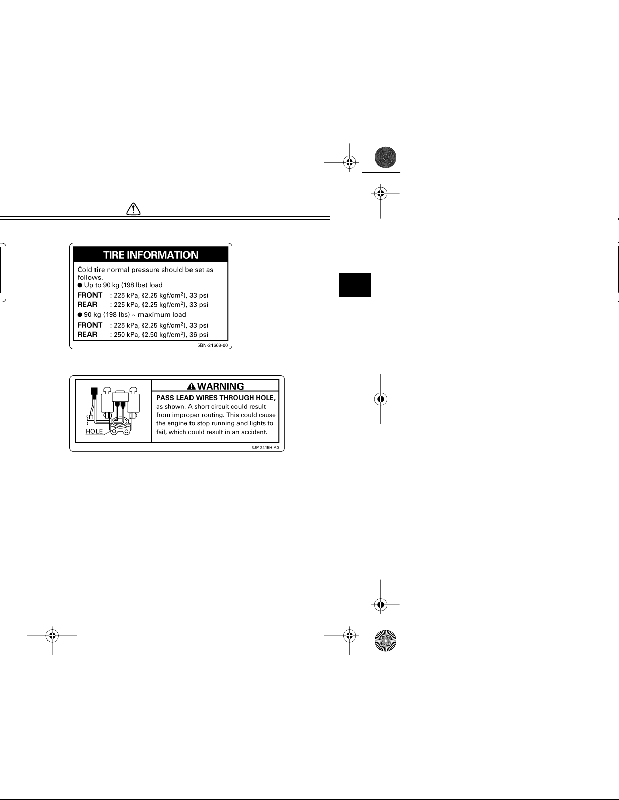
Checking the throttle cable free
play ............................................ 6-19
Valve clearance ............................ 6-20
Tires .............................................. 6-20
Cast wheels .................................. 6-22
Accessories and replacement
parts ........................................... 6-23
Clutch lever ................................... 6-23
Adjusting the brake lever free
play ............................................ 6-24
Adjusting the rear brake light
switch ......................................... 6-24
Checking the front and rear brake
pads ........................................... 6-25
Checking the brake and clutch fluid
levels ......................................... 6-25
Changing the brake and clutch
fluids .......................................... 6-26
Checking and lubricating the
cables ........................................ 6-27
Checking and lubricating the throttle
grip and cable ............................ 6-27
Checking and lubricating the brake
and shift pedals ......................... 6-27
Checking and lubricating the brake
and clutch levers ........................ 6-28
Checking and lubricating the
centerstand and sidestand ........ 6-28
Lubricating the rear suspension .... 6-29
Checking the front fork .................. 6-29
Checking the steering ................... 6-30

TABLE OF CONTENTS
1-1
motorist’s blind spot.
●
Many accidents involve inexperienced operators. In fact, many operators who have been involved in
accidents do not even have a current motorcycle license.
●
Make sure that you are qualified
and that you only lend your motorcycle to other qualified operators.
●
Know your skills and limits.
Staying within your limits may
help you to avoid an accident.
●
We recommend that you practice riding your motorcycle
where there is no traffic until you
have become thoroughly familiar with the motorcycle and all of
its controls.
●
Many accidents have been caused
by error of the motorcycle operator. A typical error made by the operator is veering wide on a turn
due to EXCESSIVE SPEED or undercornering (insufficient lean angle for the speed).
●
Always obey the speed limit and
never travel faster than warrant-

SAFETY INFORMATION
1-2
1
Modifications
Modifications made to this motorcycle
not approved by Yamaha, or the removal of original equipment, may render the motorcycle unsafe for use and
may cause severe personal injury.
Modifications may also make your motorcycle illegal to use.
Loading and accessories
Adding accessories or cargo to your
motorcycle can adversely affect stability and handling if the weight distribution
of the motorcycle is changed. To avoid
the possibility of an accident, use extreme caution when adding cargo or
accessories to your motorcycle. Use
extra care when riding a motorcycle
that has added cargo or accessories.
Here are some general guidelines to
follow if loading cargo or adding accessories to your motorcycle:
Loading
The total weight of the operator, passenger, accessories and cargo must
not exceed the maximum load limit.
1-3
namic changes. If accessories
are added to the handlebar or
front fork area, they must be as
lightweight as possible and
should be kept to a minimum.
●
Bulky or large accessories may
seriously affect the stability of
the motorcycle due to aerodynamic effects. Wind may attempt to lift the motorcycle, or
the motorcycle may become unstable in cross winds. These accessories may also cause
instability when passing or being
passed by large vehicles.
●
Certain accessories can displace the operator from his or
her normal riding position. This
improper position limits the freedom of movement of the operator and may limit control ability,
therefore, such accessories are
not recommended.
●
Use caution when adding electrical accessories. If electrical accessories exceed the capacity of the
motorcycle’s electrical system, an
electric failure could result, which
SAFETY INFORMATION
1-4
1
1-5
EAU10381
SAFETY INFORMATION
1-6
1
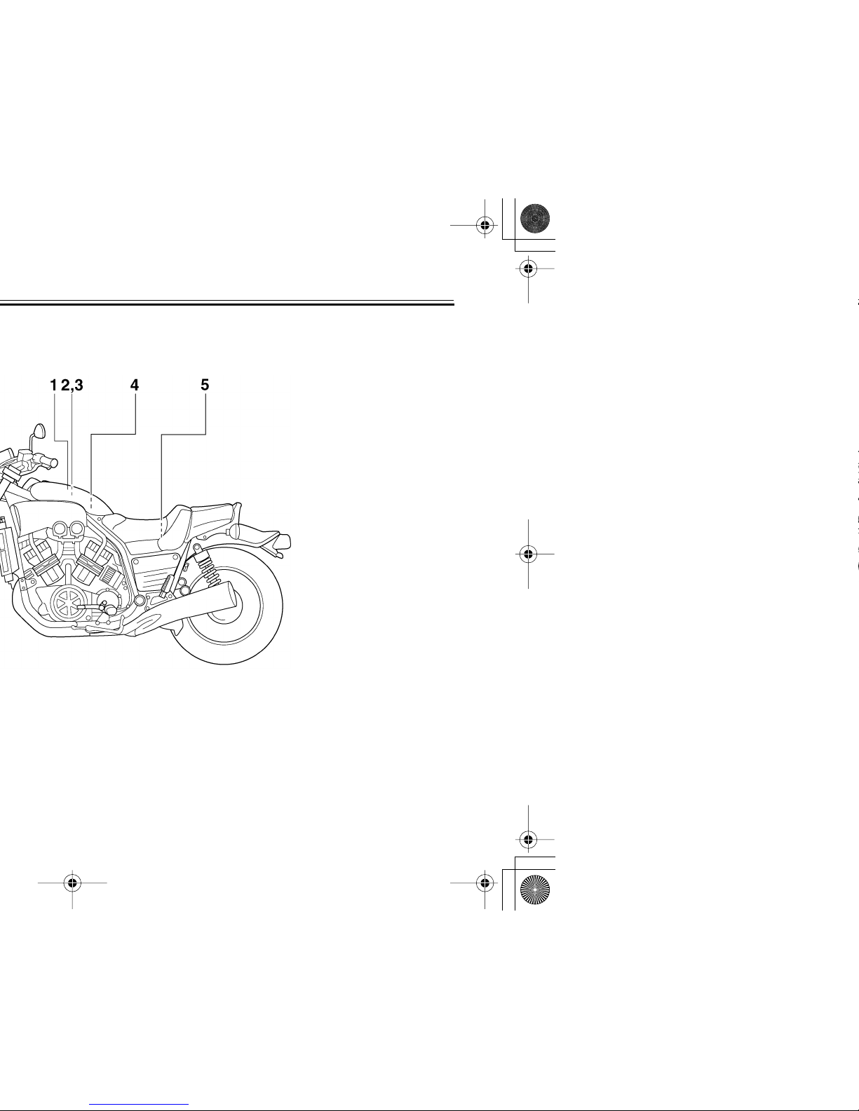
4
5
2-1
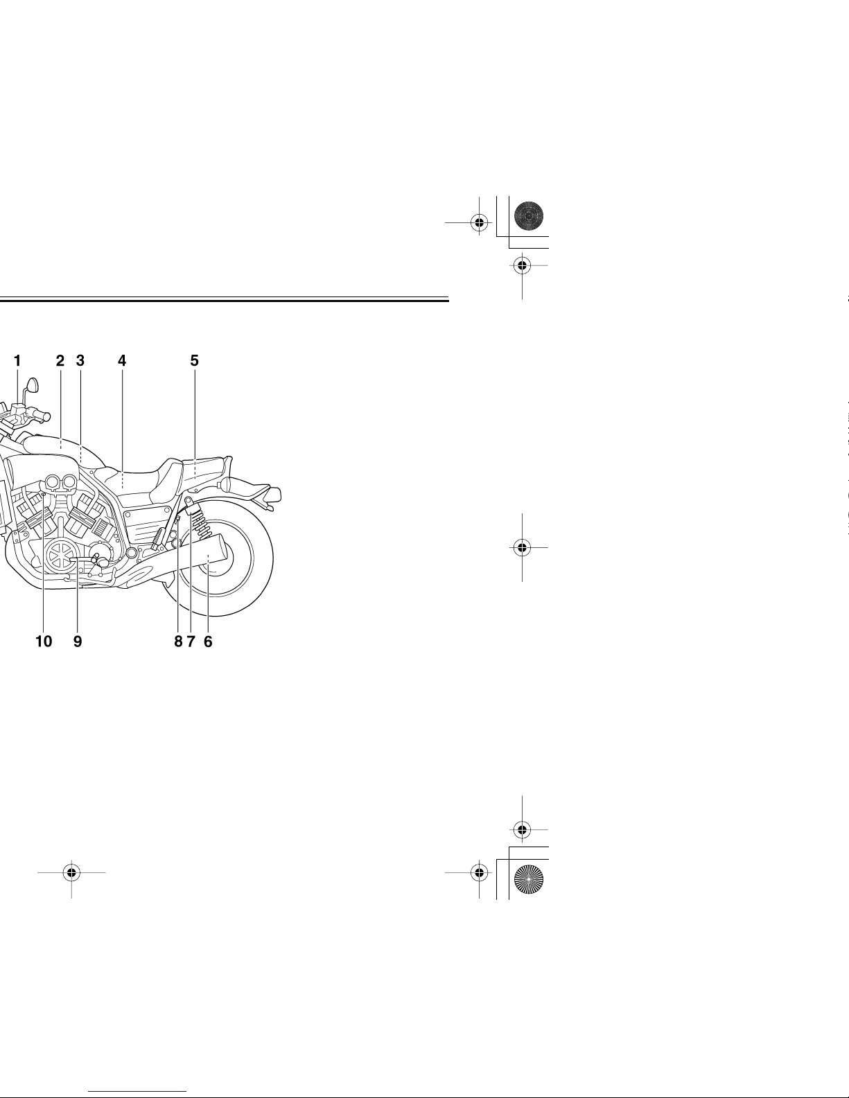
EAU10410
DESCRIPTION
2-2
2
3
4
5
6
7
8
9
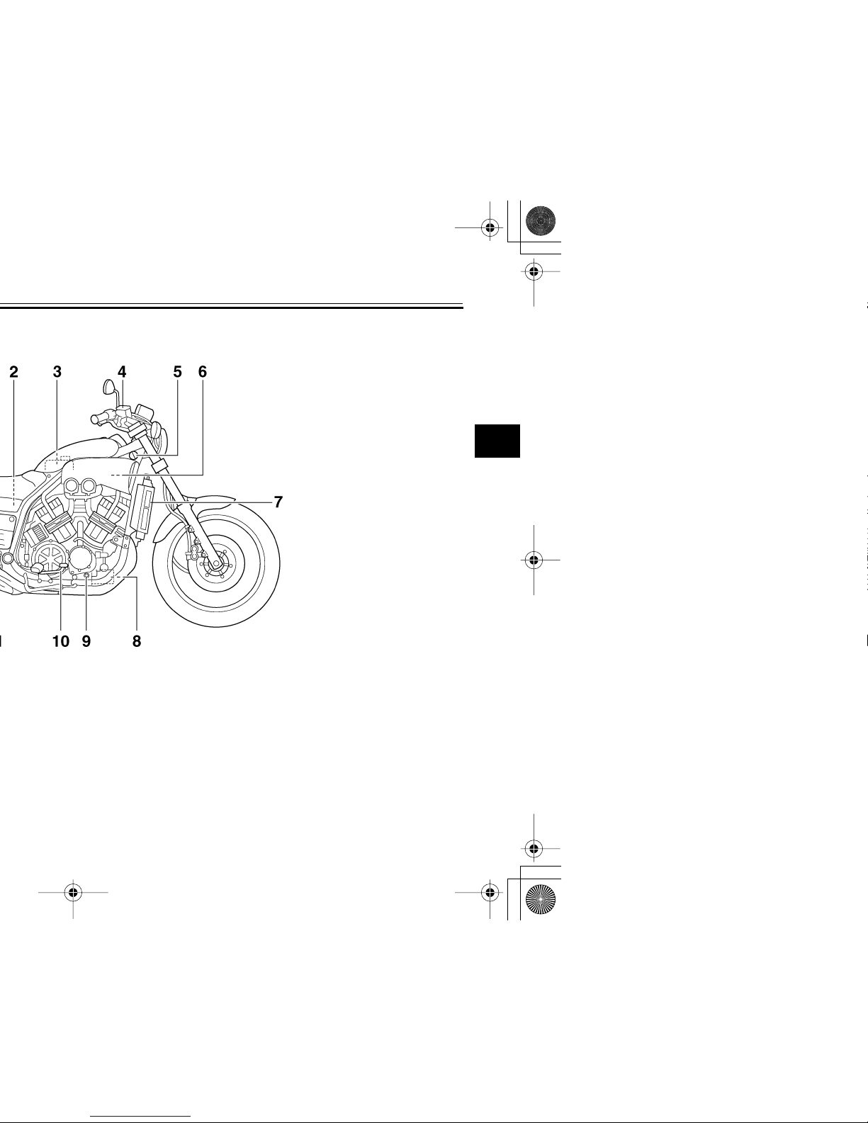
EAU10420
2-3
EAU10430
3-1
2
3
4
5
6
7
8
9
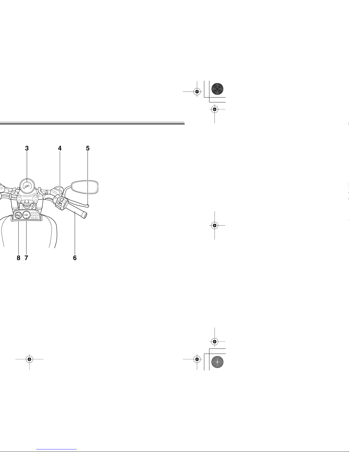
EAU10822
ECA11020
EAU11003
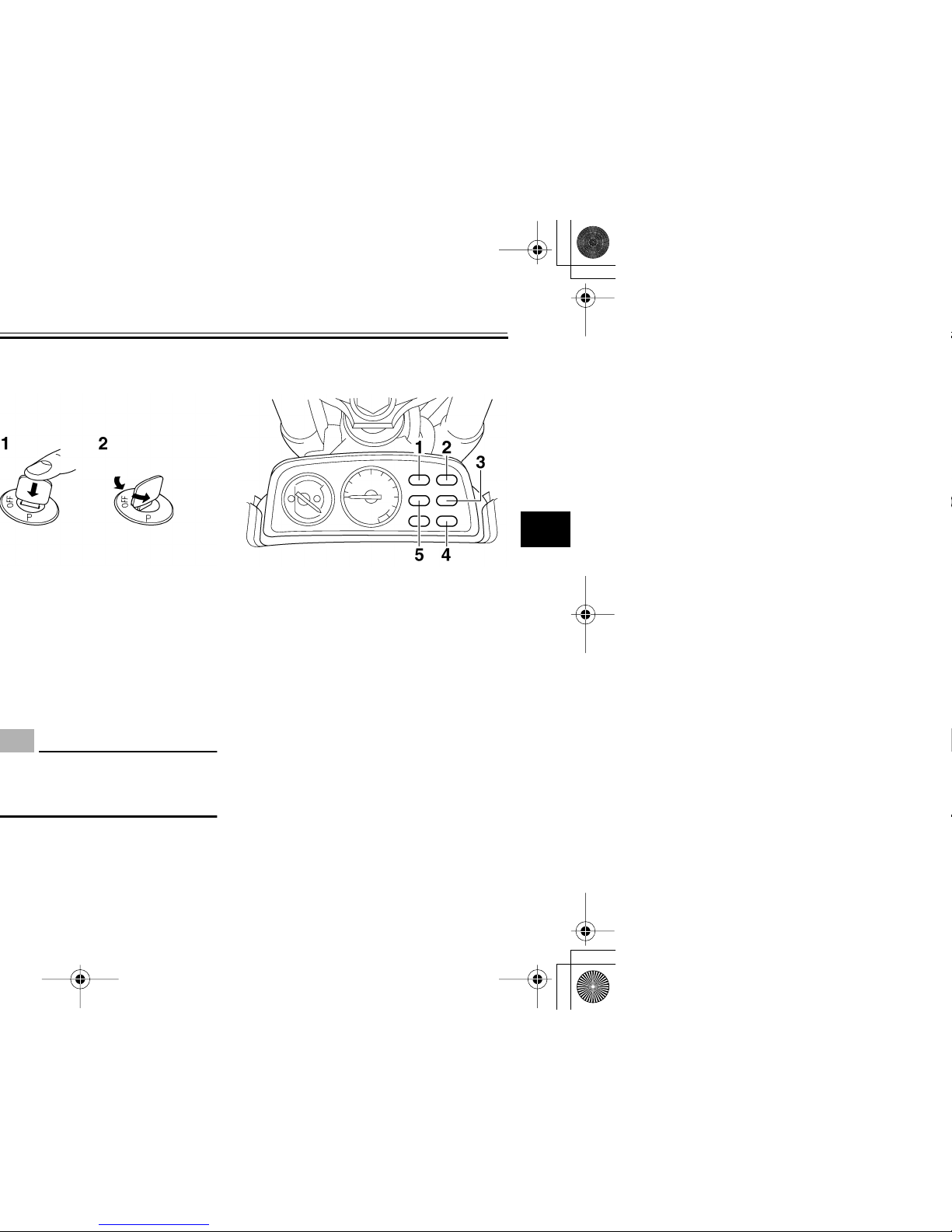
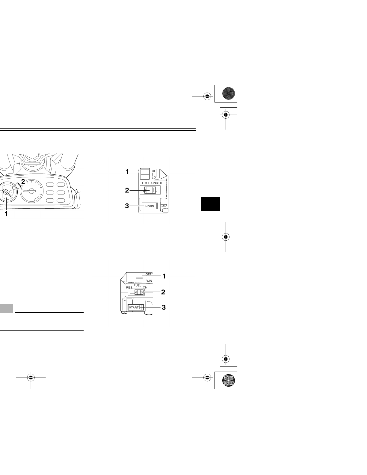
Indicator and warning lights
EAU11040
Turn signal indicator light “TURN”
This indicator light flashes when the
turn signal switch is pushed to the left or
right.
EAU11070
Neutral indicator light “NEUTRAL”
This indicator light comes on when the
transmission is in the neutral position.
1. Neutral indicator light “NEUTRAL”
2. Turn signal indicator light “TURN”
3. Fuel level warning light “FUEL”
4. High beam indicator light “HIGH BEAM”
5. Oil level warning light “OIL LEVEL”
3-2
EAU32320
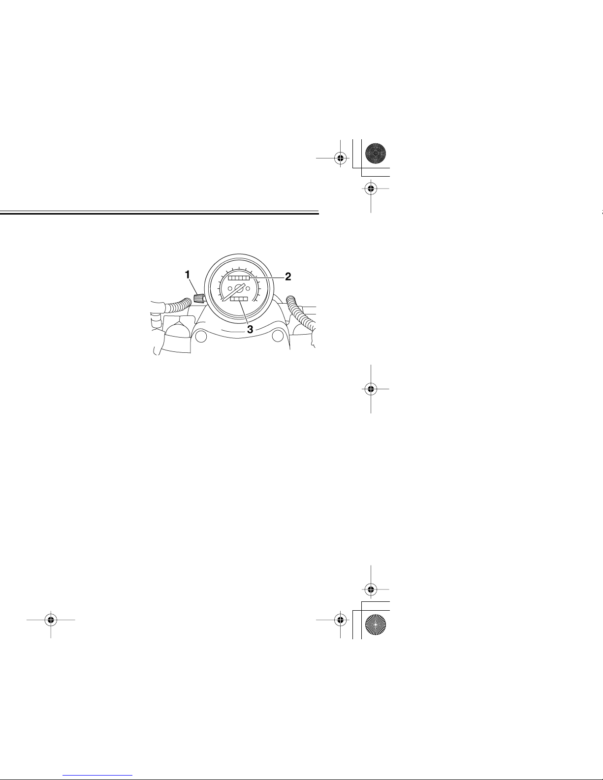
EAU11630
Speedometer unit
The speedometer unit is equipped with
a speedometer, an odometer and a
tripmeter. The speedometer shows
riding speed. The odometer shows the
total distance traveled. The tripmeter
shows the distance traveled since it
was last set to zero with the reset knob.
The tripmeter can be used to estimate
the distance that can be traveled with a
full tank of fuel. This information will enable you to plan future fuel stops.
1. Tripmeter reset knob
2. Odometer
3. Tripmeter
3-3
2
3
4
5
6
7
8
9
EAU12171
ECA10020
EAU12343
Handlebar switches
Left
Right
1. Dimmer switch “LIGHTS”
2. Turn signal switch “TURN”
3. Horn switch “HORN”
1. Engine stop switch “ENGINE STOP”
2. Fuel reserve switch “FUEL”
3. Start switch “START”
3-4
EAU12510
EAU12650
EAU12690
ECA10050
EAU12790
NOTE:
After switching to “RES”, approximately
3.0 L (0.79 US gal) (0.66 Imp.gal) of
fuel remain in the fuel tank.
3-5
2
3
4
5
6
7
8
9
EAU12870
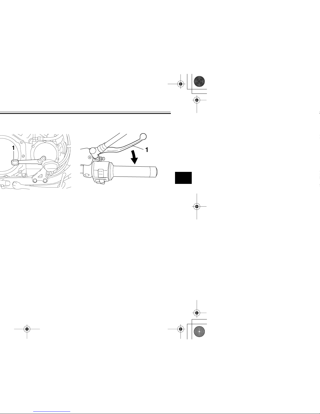
EAU12890
Brake lever
The brake lever is located at the right
handlebar grip. To apply the front
brake, pull the lever toward the handlebar grip.
1. Brake lever
3-6
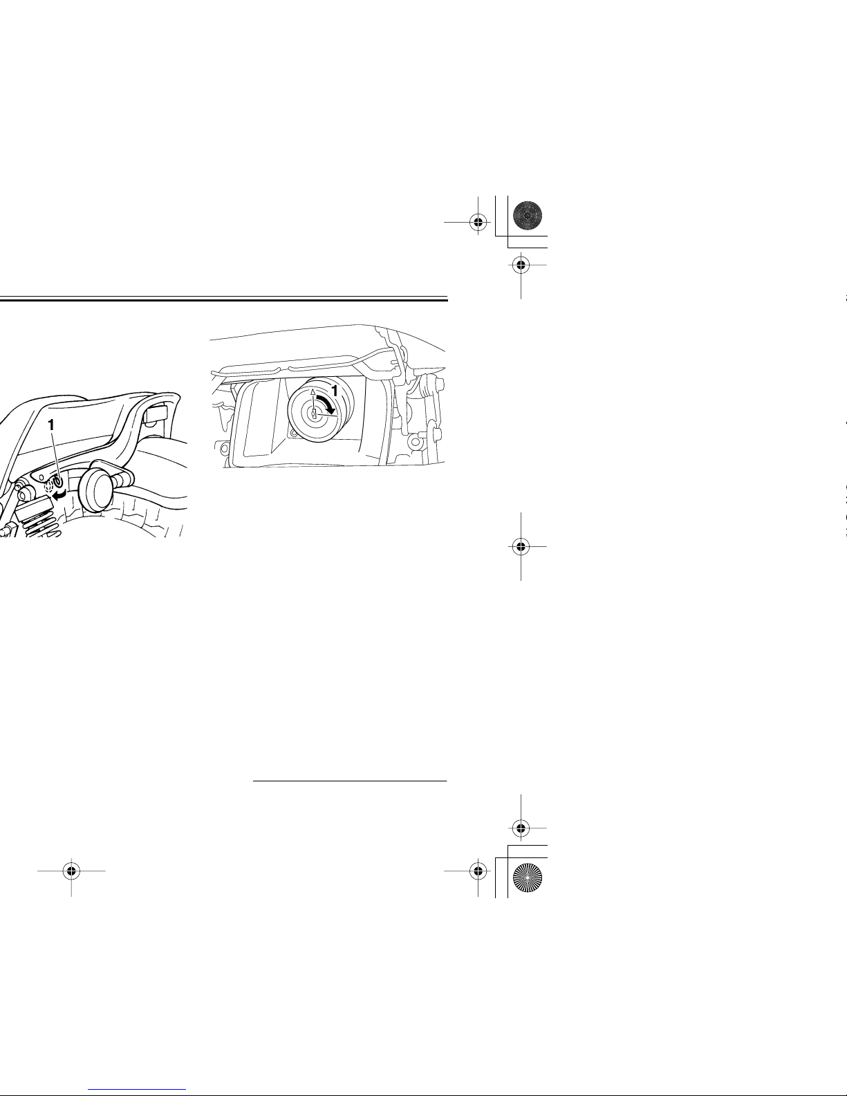
EAU13060
2. Insert the key into the lock, and
then turn it 1/4 turn clockwise. The
lock will be released and the fuel
tank cap can be removed.
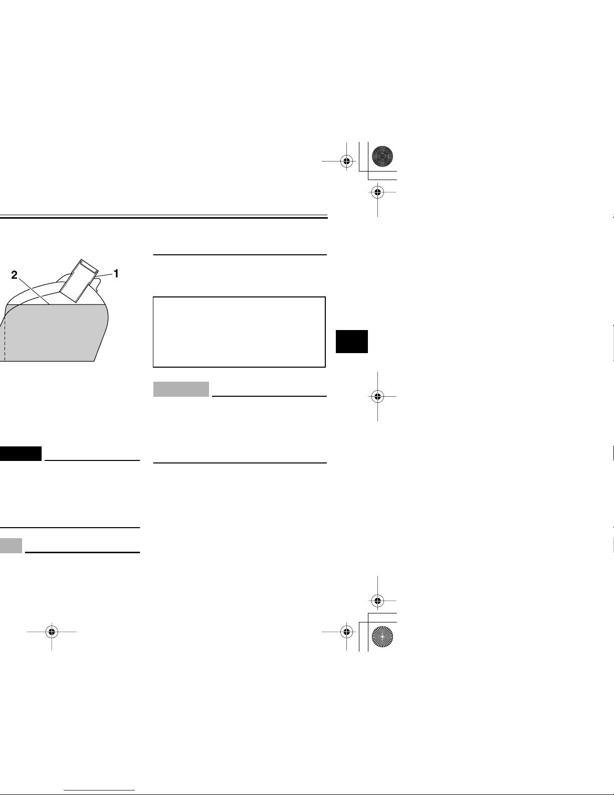
To install the fuel tank cap
1. Insert the fuel tank cap into the
tank opening with the key inserted
in the lock and with the mark on the
cap facing forward.
2. Turn the key counterclockwise to
the original position, and then remove it.
3. Slide the rider seat backrest rear-
ward and push it down.
NOTE:
The fuel tank cap cannot be installed
1. Unlock.
3-7
2
3
4
5
6
7
8
9
EAU13210
EWA10880
ECA10070
fuel may deteriorate painted surfaces or plastic parts.
EAU13300
CAUTION:
ECA11400
Use only unleaded gasoline. The use
of leaded gasoline will cause severe
damage to internal engine parts,
such as the valves and piston rings,
as well as to the exhaust system.
Your Yamaha engine has been designed to use regular unleaded gasoline with a pump octane number
[(R+M)/2] of 86 or higher, or a research
octane number of 91 or higher. If
knocking (or pinging) occurs, use a
gasoline of a different brand or premium unleaded fuel. Use of unleaded fuel
will extend spark plug life and reduce
Recommended fuel:
UNLEADED GASOLINE ONLY
Fuel tank capacity:
15.0 L (3.96 US gal) (3.30 Imp.gal)
Fuel reserve amount:
3.0 L (0.79 US gal) (0.66 Imp.gal)
3-8
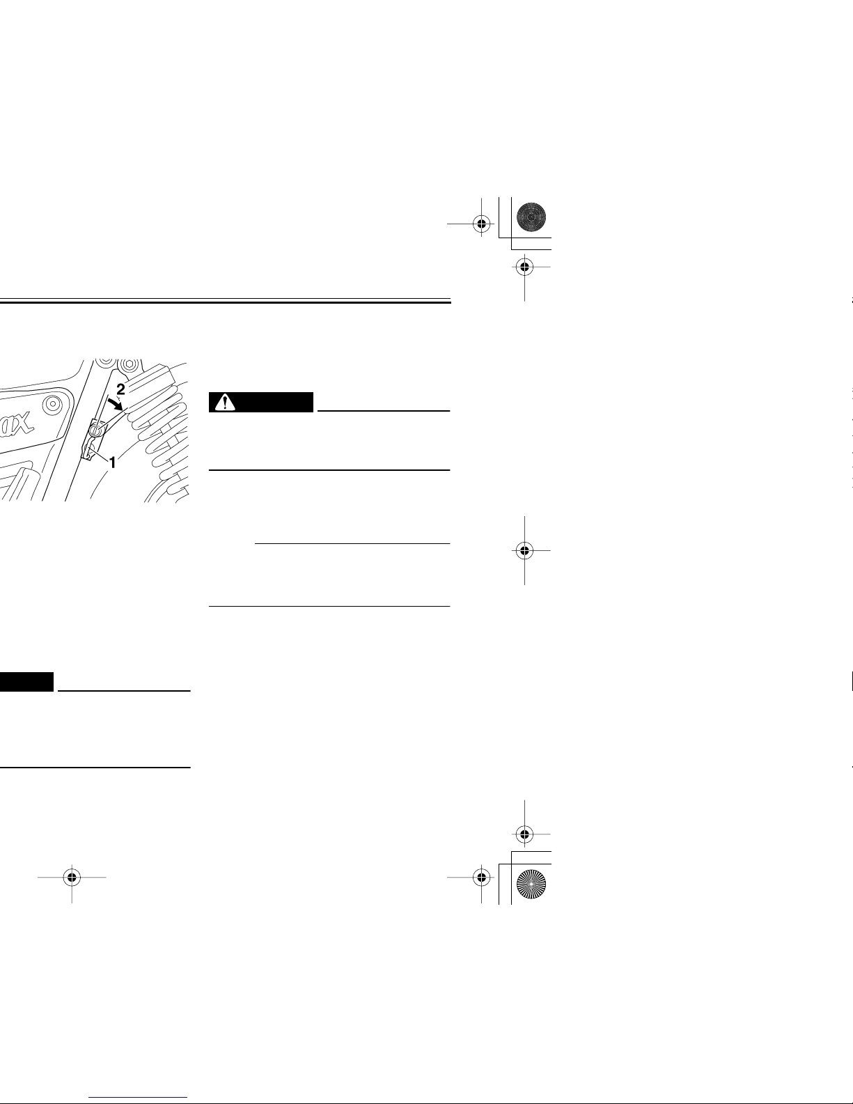
EAU13630
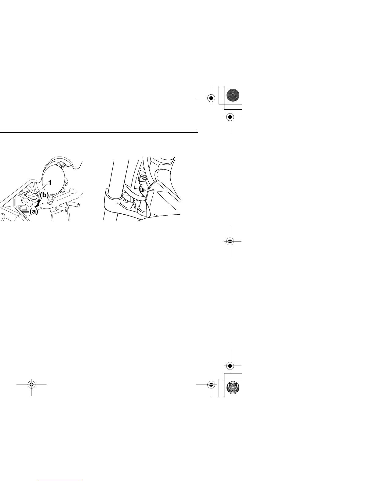
EAU13730
Steering lock
To lock the steering
1. Turn the handlebar all the way to
the right.
2. Open the steering lock cover, and
then insert the key.
3. Turn the key 1/8 turn counterclock-
wise, push it in while turning the
handlebar slightly to the left, and
then turn the key 1/8 turn clockwise.
4. Check that the steering is locked,
remove the key, and then close the
lock cover.
1. Steering lock
1
3-9
2
3
4
5
6
7
8
9
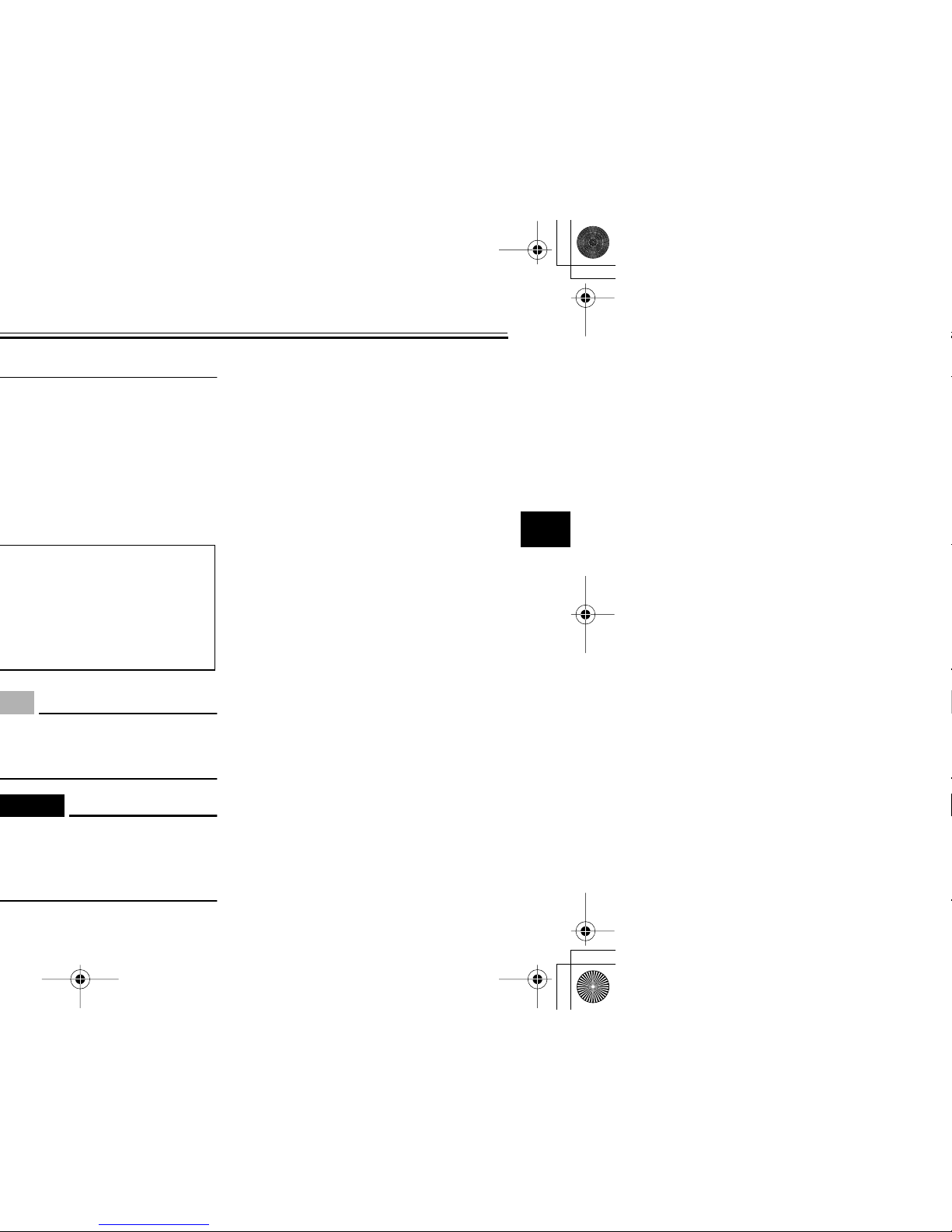
EAU14230
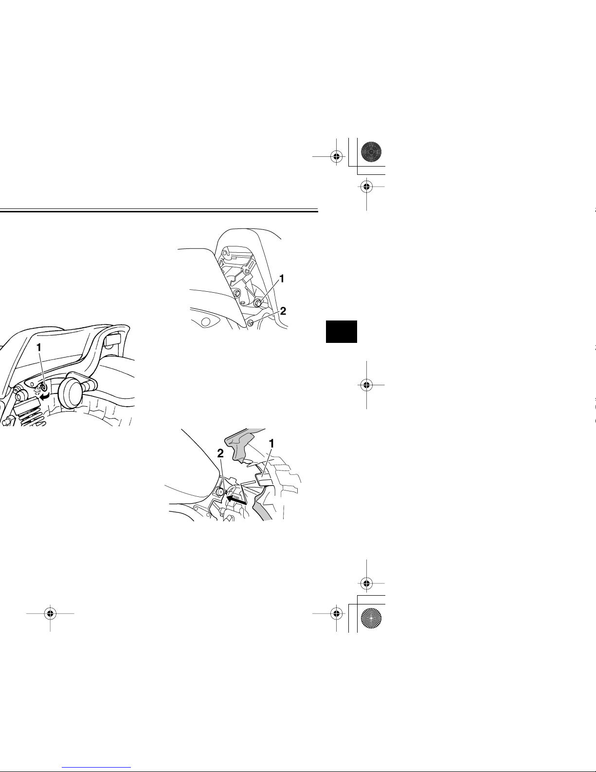
To install the rider seat
1. Insert the projection on the front of
the rider seat into the seat holder
as shown.
1. Bolt
2. Screw
1. Projection
2. Seat holder
3-10
EAU14281
EWA10160
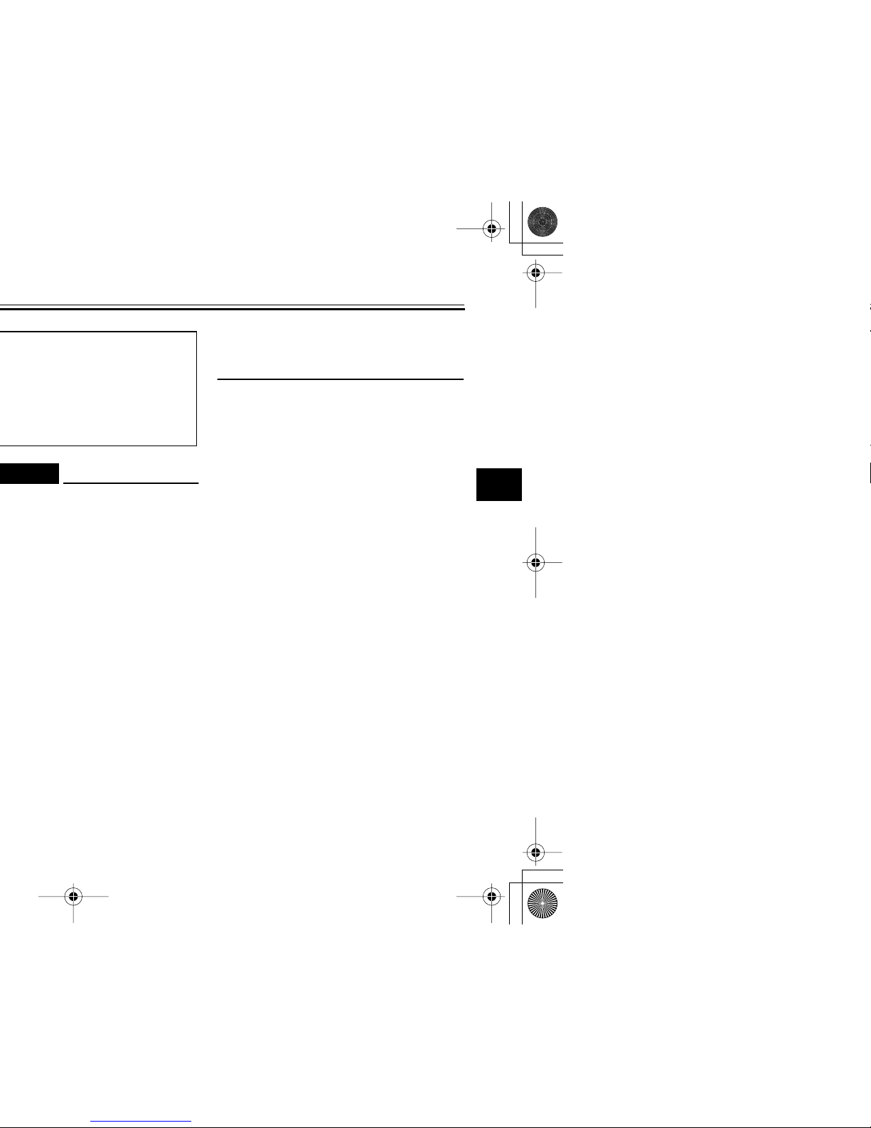
EAU14660
Adjusting the front fork
This front fork is equipped with air
valves for adjusting the spring rate.
WARNING
EWA10180
Always adjust both fork legs equally, otherwise poor handling and loss
of stability may result.
Adjust the spring rate as follows.
1. Elevate the front wheel by placing
the vehicle on the centerstand.
NOTE:
When checking and adjusting the air
pressure, there should be no weight on
the front end of the vehicle.
2. Remove the air valve cap from
each fork leg.
3-11
2
3
4
5
6
7
8
9
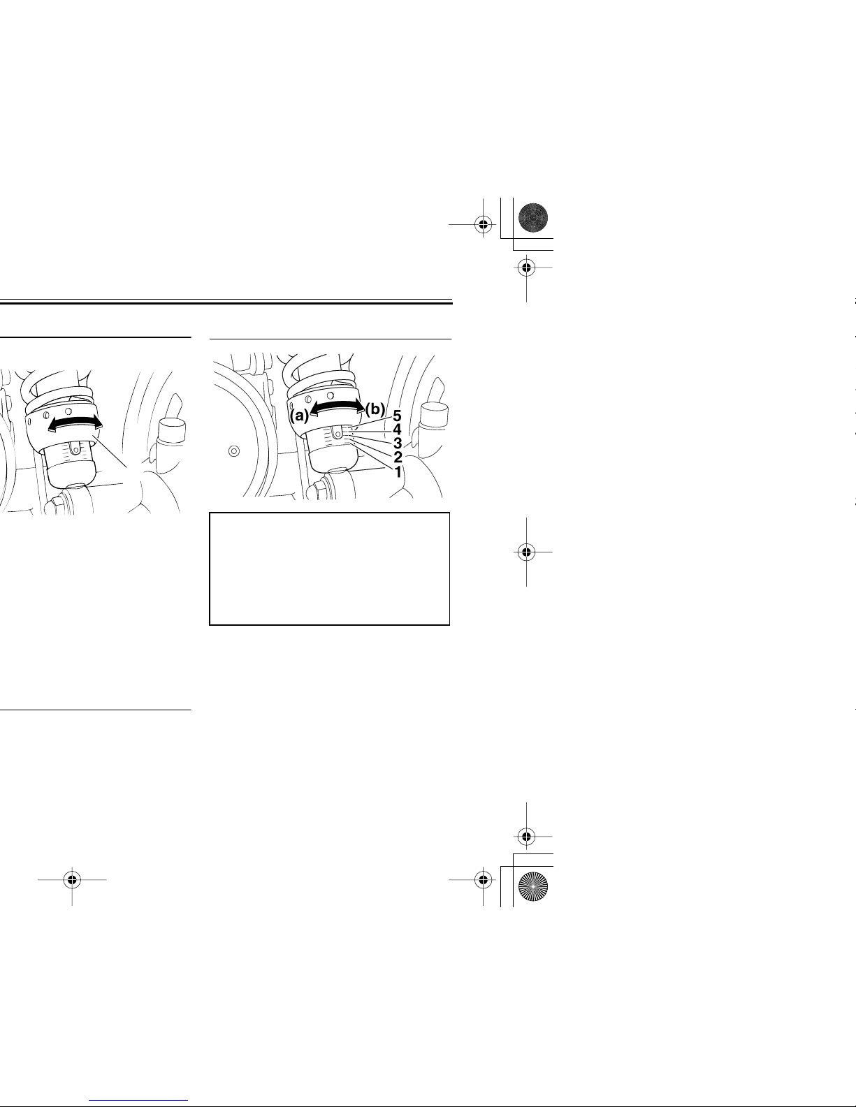
ECA10090
EWA11180
5. Securely install the air valve caps.
2
)
2
)
3-12
justment.
1
(a)
(b)
Spring preload:
Minimum (soft):
1
Standard:
1
Maximum (hard):
5
3-13
2
3
4
5
6
7
8
9
EWA10230
formance.
●
Always have a Yamaha dealer
service the shock absorbers.
3-14
ECA10181
EAU15301
Sidestand
The sidestand is located on the left side
of the frame. Raise the sidestand or
lower it with your foot while holding the
vehicle upright.
NOTE:
The built-in sidestand switch is part of
the ignition circuit cut-off system, which
cuts the ignition in certain situations.
(See further down for an explanation of
the ignition circuit cut-off system.)
WARNING
EWA10240
The vehicle must not be ridden with
the sidestand down, or if the sidestand cannot be properly moved up
(or does not stay up), otherwise the
sidestand could contact the ground
and distract the operator, resulting
in a possible loss of control.
Yamaha’s ignition circuit cut-off
system has been designed to assist
the operator in fulfilling the responsibility of raising the sidestand before starting off. Therefore, check
this system regularly as described
below and have a Yamaha dealer re-