

Page 1

READ THIS MANUAL CAREFULLY!
It contains important safety information.
OWNER’S/OPERATOR’S MANUAL
G23E
LIT-19626-01-18
JU6-F8199-10
Page 2

Page 3

1-
INTRODUCTION
Congratulations on your purchase of a Yamaha utility vehicle. This manual contains information you
will need for proper operation, maintenance, and care of your utility vehicle. A thorough understanding of these simple instructions will help you to obtain maximum enjoyment from your new Yamaha.
If you have any questions about the operation or maintenance of your utility vehicle, please consult a Yamaha dealer.
TECHNICAL SERVICE DEPT
YAMAHA GOLF-CAR COMPANY
G23E
OWNER’S/OPERATOR’S
MANUAL
© 2004 by Yamaha Golf-Car Company
2nd edition
All rights reserved. Any reprinting
or unauthorized use without the
written permission of
Yamaha Golf-Car Company
is expressly prohibited.
Printed in U.S.A.
P/N LIT-19626-01-18
Page 4
IMPORTANT MANUAL INFORMATION
WARNING
CAUTION:
NOTE:
Particularly important information is distinguished in this manual by the following notations:
The Safety Alert Symbol means ATTENTION! BE ALERT! YOUR
SAFETY IS INVOLVED!
Failure to follow WARNING instructions could result in severe
injury or death to the utility vehicle occupants, a bystander, or a
person inspecting or repairing the utility vehicle.
This message describes special precautions that must be taken to
avoid damage to the utility vehicle.
This message provides additional key information.
NOTE:
_
●
Yamaha continually seeks advancements in product design and quality; therefore, while this
manual contains the most current product information available at the time of printing, there
may be minor discrepancies between your utility vehicle and this manual. If you have any
questions concerning this manual, please consult your Yamaha dealer.
●
This manual should be considered a permanent part of your utility vehicle and should remain
with the car when resold.
_
WARNING
_
Read and understand this manual completely before operating your utility vehicle.
Page 5

YAMAHA GOLF-CAR COMPANY
UTILITY VEHICLE LIMITED WARRANTY
Yamaha Golf-Car Company hereby warrants that any
new Utility Vehicle purchased from an authorized
Yamaha dealer in the United States, will be free from
defects in material and workmanship for the period of
time stated herein, subject to the stated limitations.
THE PERIOD OF WARRANTY for any Utility Vehicle
will be one year from date of purchase for parts and
labor.
The warranty shall cover the entire vehicle except for
batteries, tires and rims, which are warranted by their
respective manufacturers.
DURING THE PERIOD OF WARRANTY any
authorized Yamaha Golf Car Dealer will, free of
charge, repair or replace, at Yamaha’s option, any
part adjudged defective by Yamaha due to faulty
workmanship or material from the factory. Parts used
in warranty repairs will be warranted for the balance
of the machine’s warranty period. All parts replaced
under warranty become property of Yamaha Golf-Car
Company.
GENERAL EXCLUSIONS from this warranty shall
include any failures caused by:
a.
Abnormal strain, neglect, or abuse, including lack
of proper maintenance, and use contrary to the
Owner’s/Operator’s Manual instructions.
b.
Accident or collision damage.
c.
Installation of parts or accessories that are not
original equipment.
d.
Fading, rust, or deterioration due to exposure or
ordinary wear and tear.
e.
Modification or alteration that affects the Utility
Vehicle’s condition, operation, performance, or
durability.
f.
Damage due to improper transportation.
g.
Acts of God (i.e. lightning, hail damage, flooding,
fire, etc.)
SPECIFIC EXCLUSIONS from this warranty shall
include any parts replaced due to normal wear or
routine maintenance, including oil, air filter elements,
brake shoes, spark plugs, starter and clutch drive
belts, and bed damage such as scratches, dents, or
deformation. Any charges incurred in transporting a
Utility Vehicle to and from an authorized Yamaha Golf
Car Dealer for service or in performing field service is
also excluded from this warranty.
THE CUSTOMER’S RESPONSIBILITY under this
warranty shall be to:
Operate and maintain the Utility Vehicle as
1.
specified in the appropriate Owner’s/Operator’s
Manual;
Give notice to an authorized Yamaha dealer of any
2.
and all apparent defects within ten (10) days after
discovery, and make the machine available at that
time for inspection and repairs by the dealer’s
authorized representative.
WARRANTY TRANSFER: To transfer any remaining
warranty from the original purchaser to any
subsequent purchaser, it is imperative that the
machine be inspected and registered for warranty by
an authorized Yamaha Golf Car Dealer. In order for
this warranty to remain in effect, this inspection and
registration must take place within ten (10) days after
transfer. An inspection and registration fee will be
charged for this service.
YAMAHA GOLF-CAR COMPANY MAKES NO OTHER
WARRANTY OF ANY KIND, EXPRESSED OR
IMPLIED. ALL IMPLIED WARRANTIES OF
MERCHANTABILITY AND FITNESS FOR A
PARTICULAR PURPOSE WHICH EXCEED THE
OBLIGATIONS AND TIME LIMITS STATED IN THIS
WARRANTY ARE HEREBY DISCLAIMED BY
YAMAHA GOLF-CAR COMPANY AND EXCLUDED
FROM THIS WARRANTY.
SOME STATES DO NOT ALLOW LIMITATIONS ON
HOW LONG AN IMPLIED WARRANTY LASTS, SO
THE ABOVE LIMITATION MAY NOT APPLY TO YOU.
ALSO EXCLUDED FROM THIS WARRANTY ARE
ANY INCIDENTAL OR CONSEQUENTIAL
DAMAGES INCLUDING LOSS OF USE. SOME
STATES DO NOT ALLOW THE EXCLUSION OR
LIMITATION OF INCIDENTAL OR CONSEQUENTIAL
DAMAGES, SO THE ABOVE EXCLUSION MAY NOT
APPLY TO YOU.
THIS WARRANTY GIVES YOU SPECIFIC LEGAL
RIGHTS, AND YOU MAY ALSO HAVE OTHER
RIGHTS WHICH VARY FROM STATE TO STATE.
YAMAHA GOLF-CAR COMPANY
Effective Date: 01/01/04
Page 6

CONTENTS
LOCATION OF THE WARNING
1
AND SPECIFICATION LABELS....... 1-1
DESCRIPTION AND VEHICLE
2
IDENTIFICATION ............................. 2-1
Features .......................................... 2-1
Utility vehicle serial number............. 2-2
Key identification number................ 2-2
SAFETY INFORMATION.................. 3-1
3
CONTROL FUNCTIONS .................. 4-1
4
Main switch...................................... 4-1
Drive select switch........................... 4-2
Accelerator pedal ............................ 4-3
Brake pedal .....................................4-3
Parking brake pedal ........................ 4-4
Horn button...................................... 4-4
Auxiliary DC jack ............................. 4-5
Cargo bed........................................ 4-6
Tow switch....................................... 4-9
Trailer hitch bracket .........................4-9
Transmitter unit ..............................4-10
PRE-OPERATION CHECKS ............5-1
5
Pre-operation check list ...................5-2
Brakes..............................................5-3
Batteries...........................................5-3
Transmission oil...............................5-4
Accelerator pedal.............................5-4
Steering............................................5-5
Fittings and fasteners ......................5-5
Lights................................................5-5
Switches...........................................5-5
Tires .................................................5-5
OPERATION .....................................6-1
6
Starting.............................................6-1
Stopping...........................................6-2
Accessories and loading..................6-3
DRIVING YOUR VEHICLE ...............7-1
7
Getting to know your vehicle ...........7-1
Learning to operate your vehicle .....7-3
Page 7

Turning your vehicle........................ 7-3
Braking ............................................ 7-3
Going uphill ..................................... 7-4
Going downhill................................. 7-5
Rough terrain .................................. 7-6
Riding in brush or wooded areas.... 7-6
PERIODIC MAINTENANCE AND
8
ADJUSTMENT ................................. 8-1
Owner’s/Operator’s Manual............ 8-1
Periodic maintenance/
lubrication...................................... 8-2
Seat................................................. 8-3
Cargo bed ....................................... 8-3
Batteries .......................................... 8-5
Battery care..................................... 8-5
Battery charging.............................. 8-7
Battery installation........................... 8-9
Fuse replacement ......................... 8-11
Transmission oil ............................ 8-12
Wheel removal .............................. 8-13
Wheel installation.......................... 8-14
Brake adjustment .......................... 8-15
Brake pedal free play
adjustment ...................................8-15
Replacing a headlight bulb............ 8-17
Adjusting a headlight beam........... 8-18
Replacing a taillight bulb ...............8-19
CLEANING AND STORAGE ............ 9-1
9
Chassis preparation ........................ 9-1
Battery storage care ........................ 9-1
SPECIFICATIONS ..........................10-1
10
MAINTENANCE RECORD............. 11-1
11
Page 8
1-
LOCATION OF THE WARNING AND
SPECIFICATION LABELS
1-1
Page 9
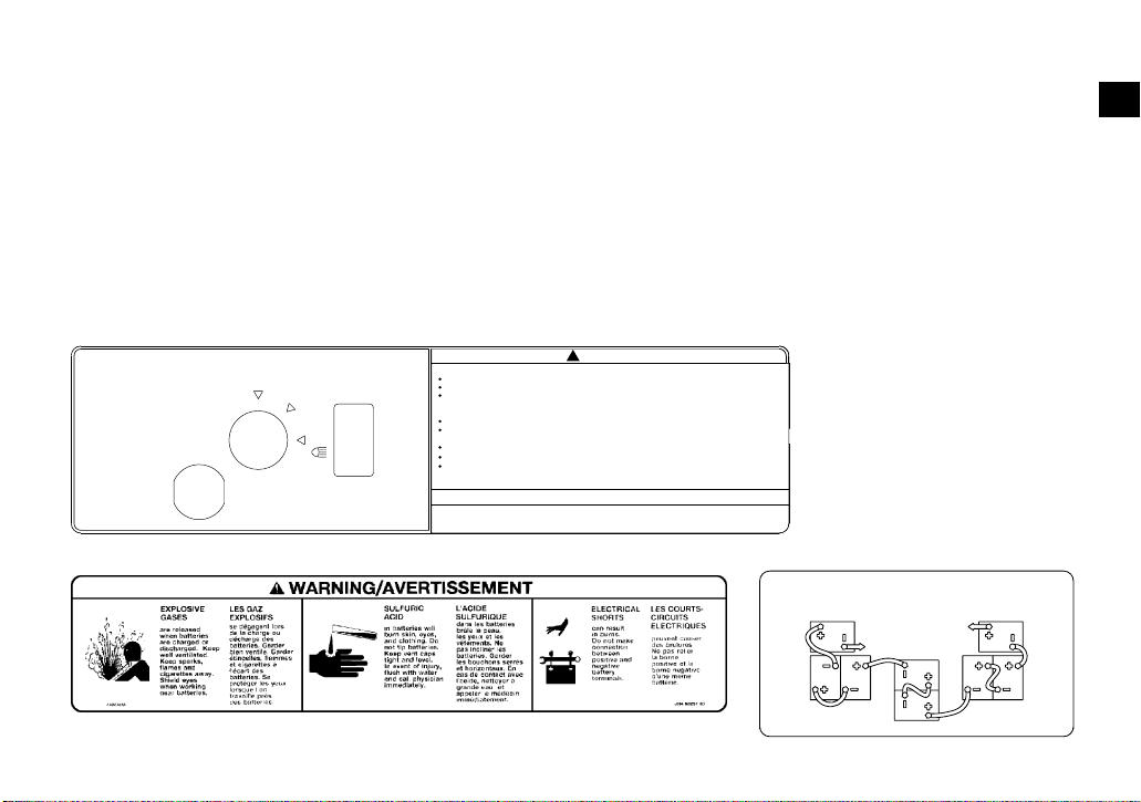
Read and understand all of the labels on your
BATTERY INSTALLATION AND
WIRE LEAD CONNECTION
vehicle. They contain important information
for safe and proper operation of your vehicle.
1
2
Never remove any labels from your vehicle. If
a label becomes difficult to read or comes off,
a replacement label is available from your
Yamaha dealer.
1
ON
FORWARD
ON
REVERSE
JU6-K7761-00
OFF
YAMAHA
2
!
Improper use can result in SEVERE INJURY or DEATH
Vehicle capacity: 1 operator and 1 passenger.
Remain seated and hold on while in motion.
This vehicle is recommended only for operators 16 and older with a valid motor vehicle
license. Adults must supervise use by minors. Check state laws for minimum age
requirements.
Drive slowly in turns.
Drive straight up and down hills-driving across the side of a hill increases the risk of
overturn.
Keep entire body inside vehicle.
Passenger and cargo can affect vehicle handling.
Vehicle rated capacity (driver, passenger, cargo, trailer, and load) 1300lb. (590kg) on level
surface.
LOCATE AND READ OWNER'S MANUAL. FOLLOW ALL INSTRUCTIONS AND WARNINGS.
This vehicle was not manufactured for use on public streets and does not comply
with federal motor vehicle safety standards applicable to passenger cars.
WARNING
ATTENTION
1-2
3
BATTERY INSTALLATION AND
WIRE LEAD CONNECTION
TO MOTOR
CONTROL -
TO RELAY
3
4
5
6
7
8
9
10
11
12
13
14
JU6-K7765-00YAMAHA
Page 10
4
WARNING
WARNING
5
WARNING
Keep hands, body, other
persons away when closing bed.
Do not operate the vehicle
YAMAHA 5UG-K7764-00
with bed up.
7
Do not fill portable fuel container (gas can) in cargo bed. Static electricity
sparks can ignite fuel vapor causing fire or explosion.
Set fuel container on the ground and touch fuel nozzle to the unopened container
before removing cap. Keep the fuel nozzle in contact with the container while
refueling. Tighten cap before putting fuel container in cargo bed.
YAMAHA
WARNING
JU7-K7767-00
8
WARNING
Improperly loading a trailer and failure to use extra care
when pulling trailer can cause an accident or injury.
Never load more than 150 lbs (68kg) tongue weight on
the towing bracket.
Do not tow more than 1000 lbs (454kg) rolling weight
(trailer plus cargo).
Allow for increased braking distance and use extreme caution
when operating on inclines.
Read carefully the loading information and trailer hitch sections
in the owner's manual.
YAMAHA
JU5-K7768-00
6
Severe INJURY or DEATH can result if you ignore the following:
Maximum Load in Cargo Bed: 800lb (363kg).
Never carry passengers or fill fuel containers in cargo bed.
Cargo can affect handling and stability.Read Owner's Manual before loading or towing.
When loading with cargo or towing a trailer: Reduce speed and allow more room to stop.
Avoid hills and rough terrain.
Be sure cargo is secured - a loose load could change handling unexpectedly.
Keep weight in the cargo bed centered, and as low and far forward as possible.
Top-heavy loads increase the risk of overturn.
YAMAHA
WARNING
9
JU5-K7766-01
1-3
Page 11
1-
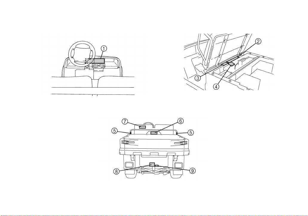
DESCRIPTION AND VEHICLE IDENTIFICATION
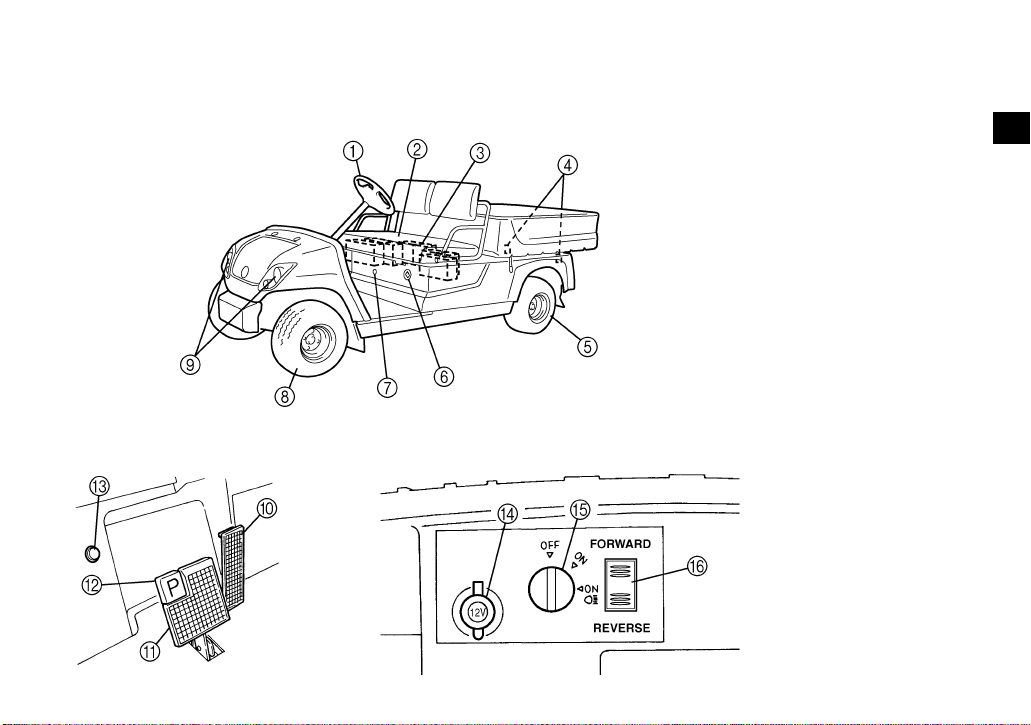
FEATURES
1. Steering wheel
2. Seat
3. Batteries
4. Taillight
5. Rear tire
6. Receptacle
7. Transmitter unit
8. Front tire
9. Headlight
10. Accelerator pedal
11. Brake pedal
12. Parking brake pedal
13. Horn button
14. Auxiliary DC jack
15. Main switch
16. Drive select switch
1
2
3
4
5
6
7
8
9
10
11
12
13
14
2-1
Page 12
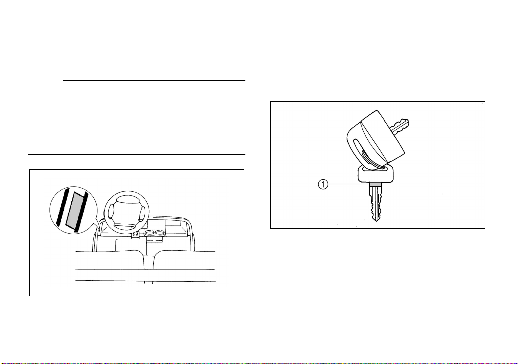
Utility vehicle serial number
The utility vehicle serial number is affixed in
the location shown.
NOTE:
The first three digits of the serial number are
for model identification; the remaining digits
are the unit production number. Keep a record
of these numbers for reference when ordering
parts from a Yamaha dealer.
Key identification number
The key identification number is stamped on
the key as shown in the following illustration.
This number can be used for ordering a new
key.
1. Key identification number
2-2
Page 13
SAFETY INFORMATION
1
SEVERE INJURY OR DEATH can result if
you do not follow these instructions:
●
Read this manual and all labels carefully
and follow the operating procedures described.
●
This vehicle is designed to carry the driver
and one passenger. Never carry passengers in the cargo bed.
●
Never give a ride to a passenger who is unable to put both feet firmly on the floorboard
while seated with his or her back against
the backrest. The passenger must hold on
to the grab rail at all times while the vehicle
is in motion.
●
Never operate this vehicle on any public
street, road, or highway, even a dirt or gravel one.
●
Never consume alcohol or drugs before or
while operating this vehicle.
●
Never operate at speeds too fast for your
skills or the conditions. Always go at a
speed that is proper for the terrain, visibility,
and operating conditions, and your experience.
●
Never attempt jumps or other stunts.
●
Always inspect your vehicle each time you
use it to be sure it is in safe operating condition. Always follow the inspection and
maintenance procedures and schedules
described in this manual.
●
Always keep both hands, arms, feet, and
legs inside the vehicle at all times during
operation. Keep your feet on the floorboard.
●
Always keep both hands on the steering
wheel when driving.
3-1
2
3
4
5
6
7
8
9
10
11
12
13
14
Page 14

●
Always go slowly and be extra careful when
operating on unfamiliar terrain. Always be
alert to changing terrain conditions when
driving the vehicle.
●
Never operate on rough, slippery, or loose
terrain.
●
Never turn at excessive speed. Do not attempt turns on steep slopes.
●
Never operate the vehicle on slopes that
are too steep for it or for your abilities. Go
straight up and down slopes.
●
Never operate on slopes that are slippery
or ones where you will not be able to see
far enough ahead of you. Never go over the
top of a slope at speed if you cannot see
what is on the other side.
●
Always check terrain carefully before going
down slopes. Go as slowly as possible.
Never go down a slope at high speed.
●
Always check for obstacles before operating in a new area.
●
Always be sure there are no obstacles or
people behind you when you operate in reverse. When it is safe to proceed in reverse, go slowly. Do not brake abruptly
when carrying loads in the cargo bed.
●
Always use the size and type of tires specified in this manual.
●
Always maintain proper tire pressure as described in this manual.
●
Never exceed the stated load capacity.
Cargo should be as far forward in the bed
as possible, and distributed evenly from
side to side. Be sure cargo is secured so
that it cannot move around during operation. Reduce speed and follow instructions
in this manual for carrying cargo or pulling a
trailer. Allow greater distance for braking.
3-2
Page 15
CONTROL FUNCTIONS
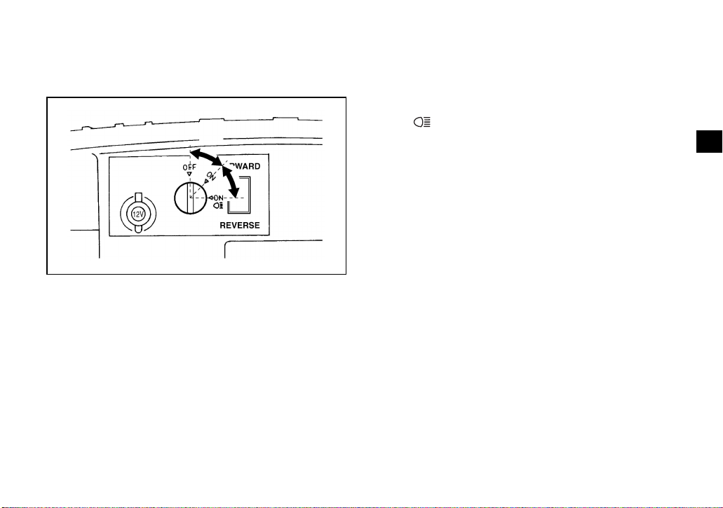
Main switch
ON:
All electrical circuits (except for the headlights
and taillights) are switched on.
The utility vehicle can be operated.
ON :
All electrical circuits are switched on.
The headlights and taillights come on.
The utility vehicle can be operated.
1
2
3
4
5
6
7
8
9
The main switch positions are as follows:
OFF:
All electrical circuits are switched off. The key
can be removed in this position only.
10
11
12
13
14
4-1
Page 16
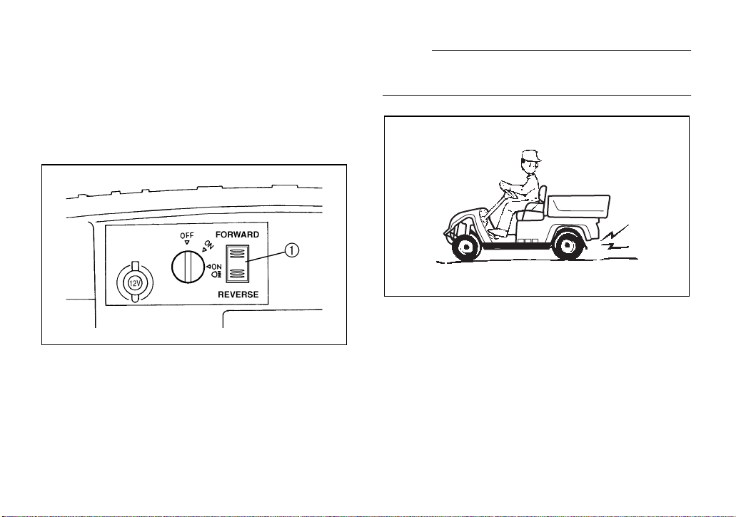
Drive select switch
The drive select switch is used for driving the
utility vehicle either forward or in reverse.
After coming to a complete stop, push the
“FORWARD” or “REVERSE” side of the
switch.
1. Drive select switch
NOTE:
The back-up buzzer will sound when the drive
select switch is set to “REVERSE.”
4-2
Page 17
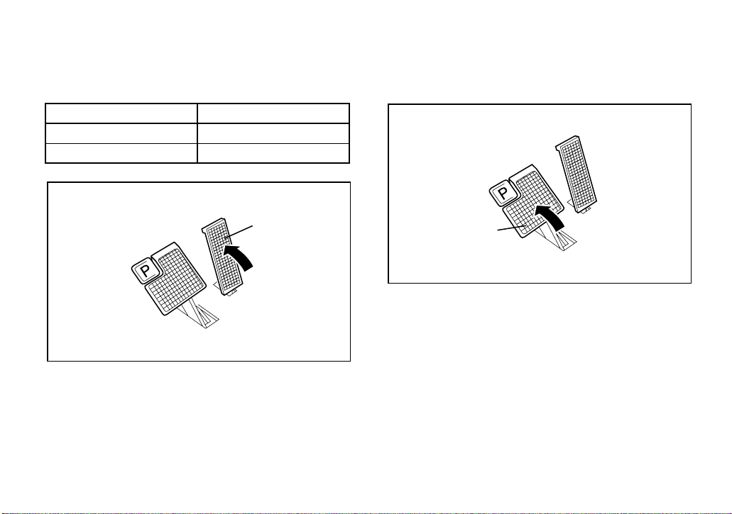
Accelerator pedal
1
The accelerator pedal controls the utility vehicle’s speed.
Action Vehicle speed
Depress pedal Increase
Release pedal Decrease
1
1. Accelerator pedal
Brake pedal
Press the brake pedal down to slow or stop
the utility vehicle.
1. Brake pedal
4-3
Page 18
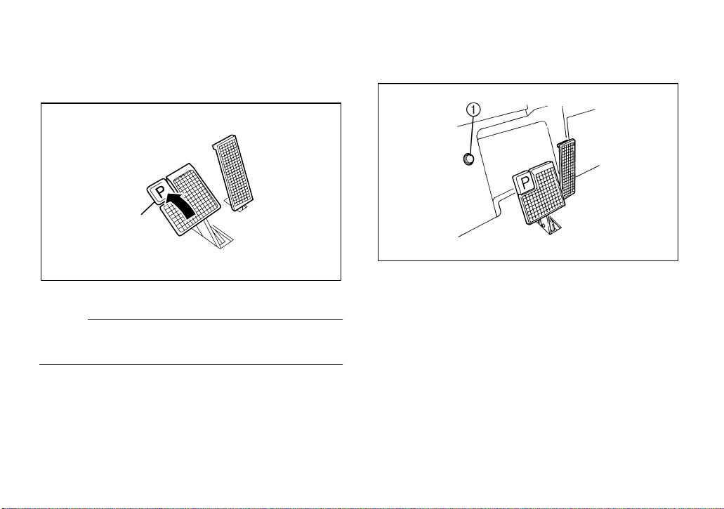
Parking brake pedal
Press the parking brake pedal down whenever parking the utility vehicle.
1
1. Parking brake pedal
NOTE:
Release the parking brake by depressing the
accelerator pedal.
Horn button
Step on the horn button to sound the horn.
1. Horn button
4-4
Page 19

Auxiliary DC jack
The auxiliary DC jack is located in the front
panel.
The auxiliary DC jack can be used for accessories such as lights, radios, etc.
The auxiliary DC jack should only be used for
short periods if the utility vehicle is not being
operated.
1. Auxiliary DC jack cap
1. Set the main switch to “ON”.
2. Open the auxiliary DC jack cap, and then
insert the accessory power plug into the
jack.
1. Auxiliary DC jack
Maximum rated capacity for the auxiliary
DC jack:
DC 12 V, 120 W (10 A)
3. Close the auxiliary DC jack cap if the jack
is not being used.
4-5
Page 20
CAUTION:
Do not use accessories requiring
●
more than the maximum rated capacity for the auxiliary DC jack. This may
overload the circuit and cause the
fuse to blow.
If accessories are used for extended
●
periods when the utility vehicle is not
being operated or with the main
switch set to “ON ”, the battery
will lose its charge.
Do not use an automotive cigarette
●
lighter or other accessories with a
plug that gets hot because the jack
can be damaged.
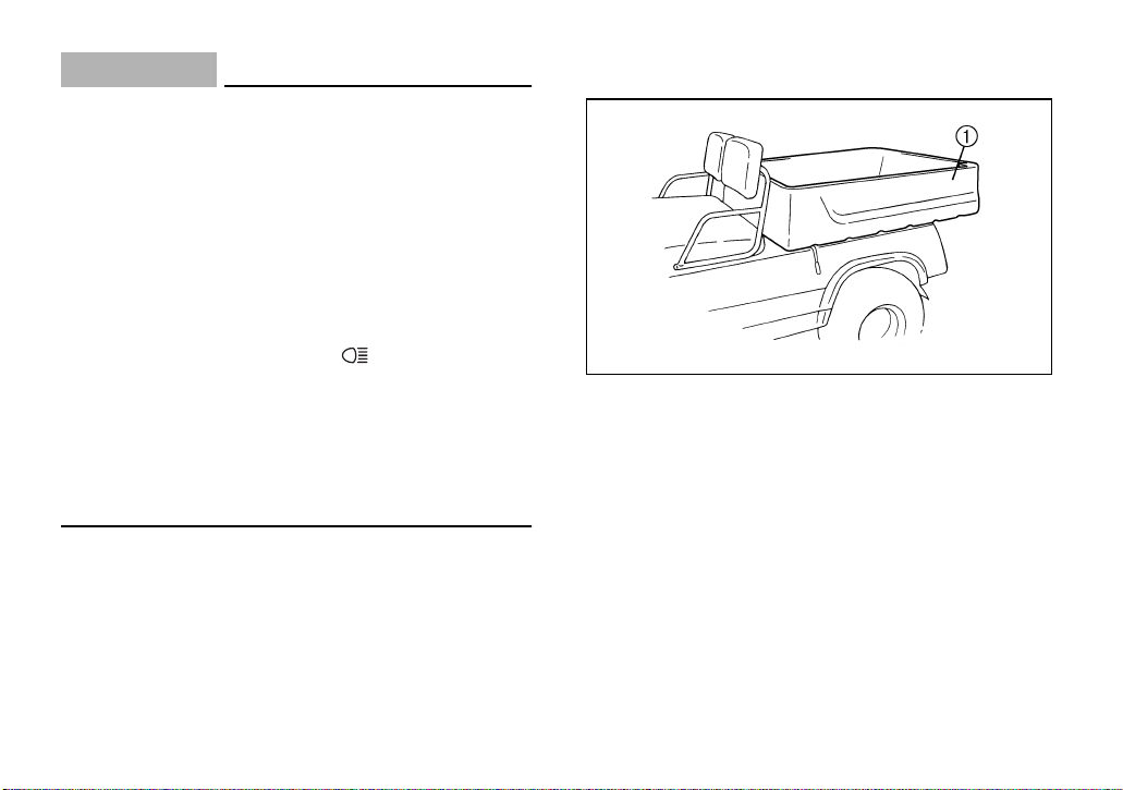
Cargo bed
1. Cargo bed
4-6
Page 21
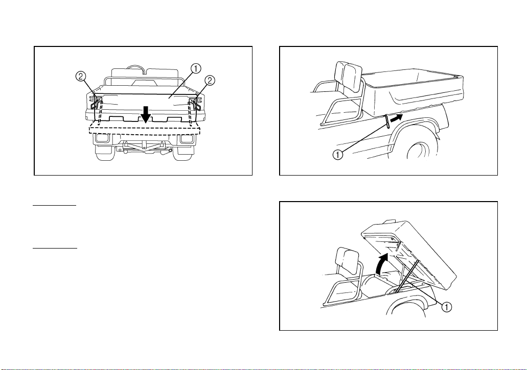
Opening and closing the tailgate
Lifting and lowering the cargo bed
1. Tailgate 2. Latch (× 2)
To open:
Unhook the latches, and then lower the tailgate.
To close:
Place the tailgate in its original position, and
then hook the latches.
1. Cargo bed release lever
1. Prop rod
4-7
Page 22

To lift:
Pull the cargo bed release lever towards the
rear, and then slowly lift up the cargo bed until
end of the prop rod hooks onto the prop rod
guide to support the cargo bed.
To lower:
Slightly lift up the cargo bed, unhook the end
of the prop rod, and then lower the cargo bed
slowly to its original position. Make sure that
the latch for the cargo bed is properly engaged.
Maximum load limit:
363 kg (800 lb)
CAUTION:
Do not lift the cargo bed by the release lever. Damage to the lever may occur.
WARNING
Apply the parking brake and remove
●
the key from the main switch before
lifting the cargo bed. Otherwise, the
utility vehicle could move unexpectedly.
Never operate the utility vehicle with
●
the cargo bed in the up position. Injury could occur if the cargo bed falls
accidentally.
Before closing the cargo bed, be sure
●
others are standing away from the
utility vehicle and that no one is sitting
on the seat. Keep hands and fingers
away from the space between the cargo bed and seat backs.
4-8
Page 23

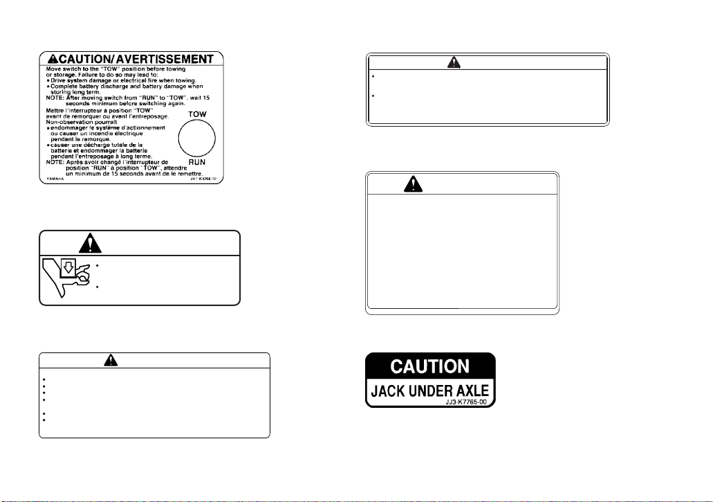
Tow switch
Before operating the vehicle, make sure the
tow switch is in the “RUN” position.
1
1. Tow switch
NOTE:
Anytime the tow switch is moved from the
“RUN” position to the “TOW” position and immediately moved back to “RUN”, there is a
delay of approximately 30 seconds before the
car will run.
Make sure the tow switch is in the “TOW” position if towing this vehicle.
Trailer hitch bracket
This vehicle is equipped with a 5 cm (2 in) receiver bracket for a standard trailer hitch.
Trailer towing equipment can be obtained at a
Yamaha dealer. (See page 6-4 for precaution
information.)
1. Trailer hitch bracket
4-9
Page 24

Transmitter unit
The transmitter unit allows you to monitor, diagnose, and program features in the motor
control unit (MCU) by way of a personal digital
assistant (PDA). The unit allows information
from the MCU of a utility vehicle to be transferred by way of infrared technology to and
from the PDA. Please refer to the G23A/E
Service Manual for operation details and instructions.
4-10
Page 25

1-
PRE-OPERATION CHECKS
Pre-operation checks should be made each
time you use your utility vehicle. Get in the
habit of performing the following checks in the
same way so that they become second nature.
WARNING
Be sure the main switch key is removed
before performing the pre-operation
checks to prevent accidental starting, and
apply the parking brake to keep the car
from moving.
1
2
3
4
5
6
7
8
9
10
11
12
13
14
5-1
Page 26

Pre-operation check list
Before using this vehicle, check the following points:
ITEM ROUTINE PAGE
Batteries
Brakes
Parking brake
Transmission oil
Accelerator pedal
Steering
Fittings and fasteners
Lights and switches
Wheels and tires
• Check battery condition.
• Charge batteries.
• Check for proper operation, condition and free play. 5-3, 8-15–8-17
• Check for proper operation, condition and free play. 5-3, 8-15–8-17
• Check for leakage. 5-4, 8-12–8-13
• Check for proper accelerator pedal operation. 5-4
• Check for proper operation. 5-5
• Check all fittings and fasteners. 5-5
• Check for proper operation. 5-5, 8-17–8-19
• Check tire pressure, wear and damage. 5-5–5-7, 8-13–8-14
5-3, 8-5–8-10
5-2
Page 27

Brakes
Brake pedal
Check for correct brake pedal free play. If the
brake pedal free play is incorrect, have a
Yamaha dealer adjust it. (See pages 8-15–
8-17.)
Check the operation of the brake pedal. It
should move smoothly and there should be a
firm feeling when the brakes are applied. If
not, have the vehicle inspected by a Yamaha
dealer.
Brake operation
Test the brakes at slow speed after starting
out to make sure they are working properly. If
the brakes do not provide proper braking performance, inspect the brake system. (See
pages 8-15–8-17.)
Batteries
Charge batteries before each use. (See page
8-5–8-10.)
Check that the batteries are held securely in
place to prevent the batteries from being damaged from vibration or jarring. Also check that
no battery caps are missing to prevent battery
acid from spilling from the battery. Check the
battery terminals for corrosion.
5-3
Page 28

Transmission oil
Make sure the transmission oil is at the specified level. Add oil if necessary. (See pages
8-12–8-13 for details.)
Recommended oil:
SAE 90 gear oil
Accelerator pedal
Remove the key from the main switch.
Make sure that the accelerator pedal operates
properly. It must operate smoothly and fully
spring back when released. If the accelerator
pedal does not operate properly, have a
Yamaha dealer check the pedal.
WARNIN G
POTENTIAL HAZARD
Checking operation of the accelerator
pedal with the key in the main switch.
WHAT CAN HAPPEN
The engine can start and the vehicle can
start moving when the accelerator pedal
is depressed.
HOW TO AVOID THE HAZARD
Remove the key from the main switch
before checking accelerator pedal operation.
5-4
Page 29

Steering
Park on level ground. Turn the steering wheel
to the right and left. Check for excessive free
play, abnormal noises, or a rough feeling. If
the steering does not operate properly, have a
Yamaha dealer check the steering.
Fittings and fasteners
Always check the tightness of chassis fittings
and fasteners before a ride. Take the utility
vehicle to a Yamaha dealer or refer to the Service Manual for the correct tightening torques.
Lights
Check the headlights and taillights to make
sure they are working properly. Replace or
have a Yamaha dealer replace if necessary.
Switches
Check the operation of all switches. If the
switches do not operate properly, have a
Yamaha dealer repair the switches.
Tires
Checking the tire pressure
Use a tire pressure gauge to measure the tire
pressure.
NOTE:
Measure the tire pressure twice and use the
second reading. Dust or dirt in the gauge
could cause the first reading to be incorrect.
5-5
Page 30

WARNIN G
POTENTIAL HAZARD
Operating this vehicle with improper
tires, or with improper or uneven tire
pressure.
WHAT CAN HAPPEN
Use of improper tires on this vehicle, or
operation of this vehicle with improper
or uneven tire pressure, may cause loss
of control, increasing your risk of accident.
HOW TO AVOID THE HAZARD
1. The tires listed below have been approved by Yamaha Motor Manufacturing Corporation of America for
this model. Other tire combinations
are not recommended. Use the same
brand of tires on all four wheels.
Manufacturer Size
Front Kenda or Maxxis 18 × 8.5-8 / 4 PLY
Rear Kenda or Maxxis 18 × 8.5-8 / 6 PLY
2. The tires should be set to the recommended pressure:
Recommended tire pressure
●
Front 150 kPa (1.53 kgf/cm
Rear 207 kPa (2.11 kgf/cm
2
, 21 psi)
2
, 30 psi)
Check and adjust tire pressures when
the tires are cold.
Tire pressures must be equal on both
sides.
3. Use no more than the following
pressures when seating the tire
beads.
Front 250 kPa (2.5 kgf/cm
Rear 250 kPa (2.5 kgf/cm
2
, 36 psi)
2
, 36 psi)
Higher pressures may cause the
tire to burst. Inflate the tires very
slowly and carefully. Fast inflation
could cause the tire to burst.
5-6
Page 31

Tire wear limit
When the tire groove decreases to 1 mm
(0.04 in) due to wear, replace the tire.
a. Tire wear limit
5-7
Page 32

1-
OPERATION
Starting
1. With the parking brake applied, push the
“FORWARD” or “REVERSE” side of the
drive select switch.
1. Drive select switch
CAUTION:
Do not shift from forward to reverse while
the utility vehicle is moving.
2. Turn the main switch to “ON” or “ON ”.
6-1
Page 33

3. Check that your path is clear in the direc-
2
1
tion you plan to go, and slowly depress
the accelerator pedal.
The utility vehicle will start to move.
1
Stopping
To stop the utility vehicle, gradually press
down on the brake pedal.
When the utility vehicle has come to a stop,
apply the parking brake pedal and turn the
main switch to “OFF.”
1
2
3
4
5
6
7
8
9
1. Accelerator pedal
NOTE:
The parking brake automatically releases
when the accelerator pedal is depressed.
1. Brake pedal 2. Parking brake pedal
CAUTION:
Do not hold the utility vehicle on an incline
with the accelerator – use the brake.
6-2
10
11
12
13
14
Page 34

Accessories and loading
Accessories
Accessories can affect the handling and control of your vehicle. Keep the following in mind
when considering an accessory or operating a
vehicle which has accessories.
●
Choose only accessories designed for your
vehicle. Your Yamaha dealer has a variety
of genuine Yamaha accessories. Other accessories may also be available on the
market. However, it is not possible for
Yamaha to test all non-Yamaha accesso-
ries, nor have any control over the quality or
suitability of them. Choose a genuine
Yamaha accessory, or one that is equiva-
lent in design and quality.
●
Accessories should be rigidly and securely
mounted. An accessory which can shift position or come off while you are operating
could affect your ability to control the vehicle.
●
Do not mount an accessory where it could
interfere with your ability to control the vehicle. Examples include (but are not limited
to) an object that limits your ability to turn
the steering wheel, one that limits your
view, or one that adversely affects the stability of the vehicle.
●
Use extra caution when driving a vehicle
with accessories. The vehicle may handle
differently than it does without accessories.
6-3
Page 35

WARNIN G
POTENTIAL HAZARD
Operating this vehicle with improper
modifications.
WHAT CAN HAPPEN
Improper installation of accessories or
modification of this vehicle may cause
changes in handling which in some situations could lead to an accident.
HOW TO AVOID THE HAZARD
Never modify this vehicle through improper installation or use of accessories. All parts and accessories added to
this vehicle should be genuine Yamaha
or equivalent components designed for
use on this vehicle and should be installed and used according to instructions. If you have questions, consult an
authorized Yamaha Golf Car Dealer.
EBU09600
Loading
Cargo or a trailer can change the stability and
handling of a vehicle.
You must use common sense and good judgment when carrying cargo or towing a trailer.
Keep the following points in mind:
●
Never exceed the weight limits shown. An
overloaded vehicle can be unstable.
MAXIMUM LOADING LIMIT
●
Maximum cargo bed load:
363 kg (800 lb)
●
Tow hitch
Tow weight (Including driver,
passenger, vehicle cargo and trailer
and trailer cargo):
590 kg (1300 lb)
Tongue weight: 68 kg (150 lb)
6-4
Page 36

●
Do not exceed the maximum tongue
weight. You can measure tongue weight
with a bathroom scale. Put the tongue of
the loaded trailer on the scale with the
tongue at hitch height. Adjust the load in the
trailer, if necessary, to reduce the weight on
hitch. If you are carrying cargo and towing a
trailer, include the tongue weight in the
maximum vehicle load limit.
●
Load cargo in the cargo bed as close to the
center of the vehicle as possible.
●
Tie down cargo securely in the trailer. Make
sure cargo in the trailer cannot move
around. A shifting load can cause an accident.
●
Make sure the load does not interfere with
controls or your ability to see where you are
going.
●
Drive more slowly than you would without a
load. The more weight you carry, the slower you should go.
●
Allow more braking distance. A heavier vehicle takes longer to stop.
●
Avoid making sharp turns unless at very
slow speeds.
●
Avoid hills and rough terrain. Choose terrain carefully. Added weight affects the stability and handling of the vehicle.
6-5
Page 37

WARNIN G
POTENTIAL HAZARD
Overloading this vehicle or carrying or
towing cargo improperly.
WHAT CAN HAPPEN
Could cause changes in vehicle handling which could lead to an accident.
HOW TO AVOID THE HAZARD
Never exceed the stated load capacity
for this vehicle.
Cargo should be properly distributed
and securely attached.
Reduce speed when carrying cargo or
pulling a trailer. Allow greater distance
for braking.
6-6
Page 38

1-
DRIVING YOUR VEHICLE
WARNIN G
GETTING TO KNOW YOUR VEHICLE
This off-highway utility vehicle will handle and
maneuver differently from an ordinary passenger car or other vehicle.
Before you begin to use your vehicle, be sure
you have read this Owner’s/Operator’s Manual completely and understand the operation of
the controls. Pay particular attention to the
safety information on pages 3-1–3-2. Please
also read all caution and warning labels on
your vehicle.
This vehicle is designed for the operator and
one passenger. Never carry passengers in
the cargo bed.
POTENTIAL HAZARD
Carrying a passenger in the cargo bed.
WHAT CAN HAPPEN
The passenger could fall or be struck by
objects in the cargo bed.
HOW TO AVOID THE HAZARD
Never carry a passenger in the cargo
bed. The cargo bed is designed to carry
cargo only.
7-1
Page 39

Carrying a passenger and cargo can affect
vehicle handling.
The total weight of operator, passenger, accessories, cargo, trailer tongue weight, and
the trailer must not exceed the maximum load
limit.
Maximum load limit:
590 kg (1300 lb)
WARNIN G
POTENTIAL HAZARD
Overloading this vehicle or carrying or
towing cargo improperly.
WHAT CAN HAPPEN
Could cause changes in vehicle handling which could lead to an accident.
HOW TO AVOID THE HAZARD
Never exceed the stated load capacity
for this vehicle.
Cargo should be properly distributed
and securely attached.
Reduce speed when carrying cargo or
pulling a trailer. Allow greater distance
for braking.
Remain seated and hold on when the vehicle
is in motion. Keep hands and feet inside the
vehicle at all times.
1
2
3
4
5
6
7
8
9
10
11
12
13
14
7-2
Page 40

LEARNING TO OPERATE YOUR VEHICLE
You should become familiar with the performance characteristics of the vehicle in a large,
flat area that is free of obstacles and other vehicles. Practice control of the accelerator,
brakes, steering, and forward/reverse select
switch. Drive first at slow speed and become
comfortable at that speed before gradually increasing your speed. Take the time to learn
basic operation before attempting more difficult maneuvers.
Set the parking brake. Perform the Pre-Operation Checks on pages 5-2. To start the motor, press the accelerator pedal slowly and
smoothly. The motor will operate and you will
start to accelerate. Avoid higher speeds until
you are thoroughly familiar with the operation
of your vehicle.
When slowing down or stopping, take your
foot off the accelerator pedal and smoothly
press the brake pedal. Improper use of the
brakes can cause the tires to lose traction, reducing control and increasing the possibility of
an accident. The motor stops operating when
the vehicle stops.
TURNING YOUR VEHICLE
It is possible for the vehicle to roll over or go
out of control if you attempt sharp, higher
speed turns. You should also be careful making sharp turns on rough terrain. Do not attempt to turn around or make abrupt
maneuvers on slopes.
BRAKING
Braking ability is affected by the type of terrain. In most cases, gradual application of the
brakes is more effective than abrupt braking,
particularly on loose surfaces like gravel. Always allow for greater braking distance on
rough, loose, or slippery surfaces.
7-3
Page 41

GOING UPHILL
Do not attempt to climb slopes until you have
mastered basic maneuvers on flat ground.
Use proper driving techniques to avoid overturns on hills and slopes. Drive straight up
slopes, and avoid crossing the side of a slope,
which increases your chance of rollover.
Practice first on gentle inclines before attempting slopes. Always check the terrain
carefully before attempting any slope. Use
common sense and remember that some
slopes are too steep for you to climb.
Choose carefully which slopes you attempt to
drive on. Avoid slopes with slippery surfaces
or ones where you will not be able to see far
enough ahead of you.
WARNIN G
POTENTIAL HAZARD
Operating on steep slopes.
WHAT CAN HAPPEN
The utility vehicle can overturn more
easily on steep slopes than on level surfaces or gentle inclines.
HOW TO AVOID THE HAZARD
Never operate your vehicle on slopes
too steep for it or your abilities.
Do not drive across the face of a slope.
Go straight up the slope.
Practice on smaller slopes before attempting large slopes.
Slow down when you reach the crest of the hill
if you cannot clearly see what is on the other
side - there could be another person, an obstacle, or a sharp drop off.
7-4
Page 42

If you start to lose traction or momentum
when going up a slope, and you decide you
will be unable to continue, use the brakes to
come to a stop. Do not attempt to turn the vehicle around. Instead, back down the hill as
slowly as possible, gently applying the brakes
when necessary.
GOING DOWNHILL
Check the terrain carefully before going down
a slope. When possible, choose a path that
lets you drive your vehicle straight downhill.
Carefully choose your path and drive no faster
than you will be able to react to obstacles that
may appear. If you must turn to avoid an obstacle, do not turn at a sharp angle that could
allow the vehicle to pitch or roll over.
WARNIN G
POTENTIAL HAZARD
Going down a slope improperly.
WHAT CAN HAPPEN
Could cause loss of control or cause the
vehicle to overturn.
HOW TO AVOID THE HAZARD
Always check the terrain carefully before you start down any slope. Never go
down a slope at high speed. Avoid going down a slope at an angle that would
cause the vehicle to lean sharply to one
side. Go straight down the slope where
possible.
Go as slowly as possible. If you are starting to
go too fast, apply the brakes gently. Avoid
sudden application of the brakes, which could
cause the vehicle to start sliding.
If you start to slide or skid, try to steer in the direction the vehicle is sliding to help you regain
control.
7-5
Page 43

If you must turn on the slope to avoid an obstacle, do so slowly and carefully. If the vehicle starts to tip, gradually steer in the downhill
direction if there are no obstacles in your path.
As you regain proper balance, gradually steer
again in the direction you want to go.
ROUGH TERRAIN
Avoid operating over rough terrain. Look for
obstacles that could cause damage to the vehicle or could lead to a rollover or accident.
Avoid jumping the vehicle as injury, loss of
control, and damage to the vehicle could occur.
WARNIN G
POTENTIAL HAZARD
Operating in rough terrain.
WHAT CAN HAPPEN
The vehicle can overturn or go out of
control.
HOW TO AVOID THE HAZARD
Always be alert to changing terrain. Go
slowly and be extra careful on unfamiliar terrain, so you will have enough time
to react to hidden rocks, bumps, or
holes in your path.
RIDING IN BRUSH OR WOODED AREAS
When operating in areas with brush or trees,
watch carefully on both sides and above the
vehicle for obstacles such as branches that
the vehicle might hit, causing an accident, or
for brush that might enter the vehicle as you
pass and strike the driver or passenger.
7-6
Page 44

EBU05150
1-
PERIODIC MAINTENANCE AND
ADJUSTMENT
Periodic inspection, adjustment and lubrication will keep your vehicle in the safest and
most efficient condition possible. Safety is an
obligation of the vehicle owner. The most important points of vehicle inspection, adjustment and lubrication are explained on the
following pages.
WARNING
Be sure to turn off the main switch and apply the parking brake when you perform
maintenance unless otherwise specified. If
the owner is not familiar with vehicle servicing, this work should be done by a
Yamaha dealer or other qualified mechanic.
Owner’s/Operator’s Manual
You are recommended to put this Owner’s/
Operator’s Manual in the vinyl bag and always
keep it with the vehicle.
The service information included in this manual is intended to provide you, the owner, with
the necessary information for completing your
own preventive maintenance and minor repairs.
NOTE:
_
If you do not have a torque wrench available
during a service operation requiring one, take
your vehicle to a Yamaha dealer to check the
torque settings and adjust them as necessary.
_
8-1
Page 45

PERIODIC MAINTENANCE/LUBRICATION
NOTE:
● For vehicles not equipped with an odometer or an hour meter, follow the month maintenance intervals.
● For vehicles equipped with an odometer or an hour meter, follow the km (mi) or hours maintenance intervals. However, keep in
mind that if the vehicle isn’t used for a long period of time, the month maintenance intervals should be followed.
1
2
3
ITEM ROUTINE
Batteries
Battery condition
Transmission oil
Brakes*
Accelerator pedal*
Wheels*
Wheel bearings*
Front and rear suspension*
Steering system*
Fittings and fasteners*
* Since these items require special tools, data and technical skills have a Yamaha dealer perform the service.
• Check electrolyte level.
• Check for loose or broken connections.
• Perform a discharge test.
• Check oil level/oil leakage.
• Replace. Every 4 years
• Check operation/brake shoe wear.
• Correct if necessary. Replace shoes if worn to the limit.
• Check operation and free play.
• Check balance/damage/runout.
• Repair if necessary.
• Check bearing assemblies for looseness/damage.
• Replace if damaged.
• Check operation and for leakage.
• Correct if necessary.
• Check operation and for looseness/Replace if damaged.
• Check toe-in/Adjust if necessary.
• Check all chassis fittings and fasteners.
• Correct if necessary.
Whichever
comes first
month 1 6 6 12
km
(mi)
hours 20 125 125 250
8-2
INITIAL EVERY
160
(100)
1,000
(600)
1,000
(600)
2,000
(1,200)
4
5
6
7
8
9
10
11
12
13
14
Page 46

Seat
Lift the seat to service the batteries.
1. Seat 2. Prop rod
Cargo bed
Lift the cargo bed to service the batteries.
1. Pull the cargo bed release lever towards
the rear.
2. Lift the cargo bed.
3. Lift the cargo bed up until the end of the
prop rod hooks onto the prop rod guide to
support the cargo bed.
1. Cargo bed release lever
CAUTION:
Do not lift the cargo bed by the release lever. Damage to the lever may occur.
8-3
Page 47

1. Prop rod
WARNING
Remove the key from the main switch
●
and apply the parking brake before
lifting the cargo bed. Otherwise, the
utility vehicle could move unexpectedly.
Never operate the utility vehicle with
●
the cargo bed in the up position. Injury could occur if the cargo bed falls
accidentally.
Before closing the cargo bed, be sure
●
others are standing away from the
utility vehicle and that no one is sitting
on the seat. Keep hands and fingers
away from the space between the cargo bed and seat backs.
8-4
Page 48

Batteries
Battery care
WARNING
Battery electrolyte is poisonous and dangerous, causing severe burns, etc. It contains sulfuric acid. Avoid contact with
skin, eyes, or clothing.
Antidote:
EXTERNAL: Flush with water.
INTERNAL: Drink large quantities of water
or milk. Follow with milk of magnesia,
beaten egg, or vegetable oil. Call physician immediately.
EYES: Flush with water for 15 minutes and
get prompt medical attention.
Batteries produce explosive gases.
Keep sparks, flame, cigarettes, etc., away.
Ventilate when charging or using in an enclosed space. Always shield eyes when
working near batteries.
KEEP OUT OF REACH OF CHILDREN.
Eight 6-volt deep cycle batteries provide power for your electric utility vehicle and must be
properly maintained and recharged for maximum performance and service life.
To maintain your batteries:
1. Clean the tops of the batteries with a solution of baking soda and water, as necessary, to remove corrosion.
CAUTION:
Do not allow cleaning solution to enter
battery cells.
2. Check the fluid level before and after
charging.
8-5
Page 49

Before charging:
●
only add distilled water if
fluid is below the top of the plates, and then
add just enough to cover plates.
After charging:
●
check that the fluid level is
approximately 6.4 mm (0.25 in) to 12.7 mm
(0.5 in) above the plates and 6.4 mm
(0.25 in) to 9.7 mm (0.38 in) below the level
indicator. If the fluid level is low, carefully
add distilled water. Adding distilled water
after charging helps prevent boil over.
CAUTION:
Normal tap water contains minerals which
are harmful to a battery; therefore, refill
only with distilled water.
3. Using a hydrometer, check the specific
gravity of the battery fluid in each cell
against the readings on the following
chart. Consult a Yamaha dealer if any
low readings are found, or if readings
vary more than one point between cells.
4
1
3
2
1. Battery cap 2. Plates
3. Maximum fluid level 4. Minimum fluid level
8-6
Page 50

Temperature Satisfactory Uncorrected
°F °C
120 48.9 1.244
110 43.3 1.248
100 37.8 1.252
90 32.2 1.256
80 26.7 1.260
70 21.1 1.264
60 15.6 1.268
50 10.0 1.272
40 4.4 1.276
30 -1.1 1.280
Hydrometer Reading
Battery charging
WARNING
Read and understand the Owner’s Manual
provided with your utility vehicle’s battery
charger before charging batteries.
WARNING
Explosive hydrogen gas is produced while
batteries are being charged. Only charge
batteries in well ventilated areas (a minimum of 5 air changes per hour is recommended).
To charge the batteries in your utility vehicle,
follow the instructions contained in your battery charger’s owner’s manual.
8-7
Page 51

The following is a summary of the charging
steps.
Do not attempt to recharge your utility vehicle’s batteries without thoroughly
reading and understanding the owner’s
manual provided with your charger.
1. Turn the key to the “OFF” position.
2. With the charger properly connected and
grounded (see charger’s owner’s manual), insert the DC output plug into the utility vehicle receptacle.
1. DC output plug 2. Receptacle
CAUTION:
Use only battery chargers that are rated
for use with 48 volt Yamaha Utility Vehicles. Thoroughly read and understand the
user manual supplied with your 48 volt
charger.
8-8
Page 52

WARNING
Do not disconnect the DC output cord
from the battery receptacle when the
charger is on or an arc could occur that
may cause an explosion.
3. The charger will turn off automatically
when the batteries reach full charge.
4. After the charger has turned off, disconnect the DC output plug from the utility
vehicle receptacle by grasping the plug
body and pulling the plug straight out of
the receptacle.
Battery installation
WARNING
When working with batteries, do not put
wrenches or other metal objects across
the battery terminals. An arc can occur
causing explosion of the battery.
1. Install the battery brackets by installing
and tightening the nuts.
a
1
2
a. Forward 1. Battery
2. Battery bracket
8-9
Page 53

2. Connect the wire leads as shown.
a
1
3
2
CAUTION:
Do not overtighten the battery bracket
nuts. Excessive force will damage the battery casing.
4
a. Forward 1. To receptacle
2. To motor control unit 3. To relay
4. Between batteries
WARNING
When installing batteries:
Carefully place battery cables and
●
brackets making sure that cables do
not lay across vent caps.
Always remove the negative (–) cable
●
to the motor controller first, and install
it last.
4
8-10
Page 54

Fuse replacement
The fuse is located under the seat. (See page
8-3 for seat opening and closing procedures.)
If a fuse is blown, replace it.
WARNING
Be sure to use the specified fuse. Using a
wrong fuse can cause electrical system
damage and create a fire hazard.
CAUTION:
When replacing a fuse be sure the main
switch is turned off to prevent accidental
short-circuiting.
1. Main fuse
Replacement Fuse:
Main fuse: 10 A
8-11
Page 55

Transmission oil
Transmission oil measurement
1. Place the vehicle on a level surface.
2. Remove the transmission oil filler plug
and check the oil level. It should be up to
the brim of the filler hole. If the level is
low, add sufficient oil of the recommended type to raise it to the specified level.
1. Transmission oil plug
CAUTION:
Be sure no foreign material enters the
transmission case.
3. Install the transmission oil filler plug.
Recommended oil:
SAE 90 gear oil
Oil quantity:
0.30 L (0.26 Imp qt, 0.32 US qt)
8-12
Page 56

4. Check for oil leakage. If oil leakage is
found, check for the cause.
NOTE:
For transmission oil replacement, consult a
Yamaha dealer.
Wheel removal
1. Loosen the wheel nuts.
2. Elevate the vehicle and place a suitable
stand under the frame.
3. Remove the nuts from the wheel.
4. Remove the wheel.
Y-57
8-13
Page 57

Wheel installation
1. Install the wheel and the nuts.
NOTE:
_
Tapered nuts are used for both the front and
rear wheels. Install the nut with its tapered
side towards the wheel.
1. Tapered nut
2. Lower the vehicle so that the wheel is on
the ground.
3. Tighten the wheel nuts to the specified
torque.
Wheel nut torque:
88 Nm (8.8 m·kgf, 64 ft·lbf)
8-14
Page 58

Brake adjustment
The brakes on your utility vehicle are selfadjusting.
Before you operate the vehicle, press down
on the brake pedal several times to make sure
the brakes are functioning properly.
WARNING
Consult your Yamaha dealer before using
your utility vehicle if you suspect brake
problems. Brake failure could result in a
serious accident.
Brake pedal free play adjustment
CAUTION:
Before adjusting brake pedal free play,
pump the brake pedal several times to
self-adjust the brakes.
To adjust the brake pedal free play:
1. Remove the service lid from the floor of
the utility vehicle.
Y-61a
8-15
Page 59

2. Check the brake pedal free play by
pressing against the pedal with two fingers (using light force) and measuring
the distance the pedal travels before resistance is felt.
Brake pedal free play:
20–25 mm (0.79–0.98 in)
8
1
7
1
6
1
5
a
1
4
1
3
1
2
1
11
10
9
8
7
3. If the free play distance needs adjusting,
loosen the locknut and turn the adjusting
nut in or out (in 180° increments only,
due to the cam shape of adjuster), until
the free play specification is met. Then
tighten the locknut to the specified
torque.
2
1
a. Brake pedal free play
1. Locknut 2. Adjusting nut
Tightening torque:
17 N·m (1.7 m·kgf, 12 ft·lbf)
8-16
Page 60

WARNING
Do not overtighten the locknut. The self
adjusters may not operate properly, reducing braking performance.
Replacing a headlight bulb
If a headlight bulb burns out, replace it as follows.
1. Remove the headlight bulb holder by
turning it counterclockwise.
1. Headlight bulb holder
2. Remove the defective bulb by unhooking
the headlight bulb holder projections.
8-17
Page 61

1. Headlight bulb holder projection (× 2)
3. Insert a new headlight bulb into the bulb
holder, and then hook the headlight bulb
holder projections onto the headlight
bulb.
4. Install the headlight bulb holder by turning it clockwise.
Adjusting a headlight beam
CAUTION:
It is advisable to have a Yamaha dealer
make this adjustment.
To raise the beam, turn the adjusting screw in
direction a.
To lower the beam, turn the adjusting screw in
direction b.
1. Headlight beam adjusting screw
8-18
Page 62

Replacing a taillight bulb
If a taillight bulb burns out, have a Yamaha
dealer replace it.
8-19
Page 63

1-
CLEANING AND STORAGE
Perform the following preparations when storing your utility vehicle for extended periods of
time:
NOTE:
Turn the key to “OFF”, turn the tow switch to
“TOW”, remove the key, and then store the
key in a safe place.
Battery storage care
1. Recharge the batteries and check the fluid levels at least once a month.
2. Clean the tops of the batteries with a solution of baking soda and water, as necessary, to remove corrosion.
CAUTION:
Do not allow cleaning solution to enter
battery cells.
1
2
3
4
5
6
7
Chassis preparation
1. Block up the frame to raise all wheels off
the ground.
2. Clean exterior of the utility vehicle and
apply a rust inhibitor.
3. Cover the utility vehicle with a breathable
cover and store it in a dry, well-ventilated
area.
8
9
10
11
12
13
14
9-1
Page 64

1-
SPECIFICATIONS
Model G23E
Dimensions:
Overall length 2915 mm (114.7 in)
Overall width 1243 mm (48.9 in)
Overall height (steering height) 1155 mm (45.5 in)
Height of floor 300 mm (11.8 in)
Wheelbase 1900 mm (74.8 in)
Tread:
Front 980 mm (38.6 in)
Rear 980 mm (38.6 in)
Ground clearance 115 mm (4.5 in)
Weight:
Dry weight (without batteries) 315 kg (694 lb)
Performance:
Maximum speed 24 km/h (14.9 mph)
Minimum turning radius 3.3 m (130 in)
Seating capacity 2 persons
Transmission oil:
Type SAE 90 gear oil
Quantity 0.30 L (0.26 Imp qt, 0.32 US qt)
10-1
Page 65

Model G23E
Steering system:
Type Worm and pin
Brakes:
Brake system Mechanical drum brake on front and rear wheels with
self-adjusters
Type of brake Dual internal expanding shoe
Leading/trailing shoes (self-adjusting)
Brake pedal freeplay linkage adjustment 20–25 mm (0.79–0.98 in)
Parking brake:
Type Foot type; with automatic release
Wheel:
Tire size:
Front 18 x 8.5–8 / 4 PLY
Rear 18 x 8.5–8 / 6 PLY
Tire pressure:
2
Front 140–160 kPa (1.4–1.6 kgf/cm
, 20–23 psi)
Rear 197–217 kPa (2.0–2.2 kgf/cm2, 29–31 psi)
Battery: BCI group 24
US Battery
6V Deep cycle GC-2
8 pcs./Series 110 minutes at 56 A at 80 °F
1
2
3
4
5
6
7
8
9
10
11
12
13
14
10-2
Page 66

Model G23E
Bulb voltage, wattage × quantity:
Headlight 12 V, 30 W / 30 W × 2
Taillight Sealed beam × 2
Specified fuses:
Main fuse 10 A
10-3
Page 67

1-
MAINTENANCE RECORD
Copies of work orders and/or receipts for parts you purchase and install will be required to document maintenance done in accordance with the warranty. The chart below is printed only as a reminder to you that the maintenance work is required. It is not acceptable proof of maintenance
work.
1
2
3
4
MAINTENANCE
INTERVAL
month km (mi) hours
1 160 (100) 20
6 1,000 (600) 125
12 2,000 (1,200) 250
18 3,000 (1,800) 375
24 4,000 (2,400) 500
30 5,000 (3,000) 625
36 6,000 (3,600) 750
42 7,000 (4,200) 875
48 8,000 (4,800) 1,000
54 9,000 (5,400) 1,125
60 10,000 (6,000) 1,250
DATE OF
SERVICE
MILEAGE
SERVICING DEALER
NAME AND ADDRESS
11-1
REMARKS
5
6
7
8
9
10
11
12
13
14
Page 68

Page 69

Page 70

PRINTED IN USA
2004.06-0.3×2 CR
(E)
 Loading...