


TX-761DAB
DAB/FM/AM Stereo Tuner
B
OWNER’S MANUAL
CAUTION: READ THIS BEFORE OPERATING YOUR UNIT.
Caution: Read this before operating your unit.
1 To assure the finest performance, please read this manual
carefully. Keep it in a safe place for future reference.
2 Install this sound system in a well ventilated, cool, dry, clean
place – away from direct sunlight, heat sources, vibration,
dust, moisture, and/or cold. Allow ventilation space of at
least 10 cm on the top, and 10 cm on the back of this unit.
3 Locate this unit away from other electrical appliances, motors,
or transformers to avoid humming sounds.
4 Do not expose this unit to sudden temperature changes from
cold to hot, and do not locate this unit in a environment with
high humidity (i.e. a room with a humidifier) to prevent
condensation inside this unit, which may cause an electrical
shock, fire, damage to this unit, and/or personal injury.
5 Avoid installing this unit where foreign object may fall onto
this unit and/or this unit may be exposed to liquid dripping or
splashing. On the top of this unit, do not place:
– Other components, as they may cause damage and/or
discoloration on the surface of this unit.
– Burning objects (i.e. candles), as they may cause fire,
damage to this unit, and/or personal injury.
– Containers with liquid in them, as they may fall and liquid
may cause electrical shock to the user and/or damage to
this unit.
6 Do not cover this unit with a newspaper, tablecloth, curtain,
etc. in order not to obstruct heat radiation. If the temperature
inside this unit rises, it may cause fire, damage to this unit,
and/or personal injury.
7 Do not plug in this unit to a wall outlet until all connections
are complete.
8 Do not operate this unit upside-down. It may overheat,
possibly causing damage.
9 Do not use force on switches, knobs and/or cords.
10 When disconnecting the power cable from the wall outlet,
grasp the plug; do not pull the cord.
11 Do not clean this unit with chemical solvents; this might
damage the finish. Use a clean, dry cloth.
12 Only voltage specified on this unit must be used. Using this
unit with a higher voltage than specified is dangerous and may
cause fire, damage to this unit, and/or personal injury. Yamaha
will not be held responsible for any damage resulting from use
of this unit with a voltage other than specified.
13 To prevent damage by lightning, keep the power cord and
outdoor antennas disconnected from a wall outlet or the unit
during a lightning storm.
14 Do not attempt to modify or fix this unit. Contact qualified
Yamaha service personnel when any service is needed. The
cabinet should never be opened for any reasons.
15 When not planning to use this unit for long periods of time
(i.e. vacation), disconnect the AC power plug from the wall
outlet.
16 Install this unit near the AC outlet and where the AC power
plug can be reached easily.
17 Be sure to read the “Troubleshooting” section on common
operating errors before concluding that this unit is faulty.
18 Before moving this unit, press STANDBY/ON to set this unit
in the standby mode, and disconnect the AC power plug from
the wall outlet.
19 The batteries shall not be exposed to excessive heat such as
sunshine, fire or like.
WAR NING
TO REDUCE THE RISK OF FIRE OR ELECTRIC
SHOCK, DO NOT EXPOSE THIS UNIT TO RAIN
OR MOISTURE.
This unit is not disconnected from the AC power
source as long as it is connected to the wall outlet, even
if this unit itself is turned off by STANDBY/ON. This
state is called the standby mode.
■ For U.K. customers
If the socket outlets in the home are not suitable for the
plug supplied with this appliance, it should be cut off and
an appropriate 3 pin plug fitted. For details, refer to the
instructions described below.
Note
The plug severed from the mains lead must be destroyed, as a
plug with bared flexible cord is hazardous if engaged in a live
socket outlet.
■ Special Instructions for U.K. Model
IMPORTANT
THE WIRES IN MAINS LEAD ARE COLOURED IN
ACCORDANCE WITH THE FOLLOWING CODE:
Blue: NEUTRAL
Brown: LIVE
As the colours of the wires in the mains lead of this apparatus
may not correspond with the coloured markings identifying
the terminals in your plug, proceed as follows:
The wire which is coloured BLUE must be connected to the
terminal which is marked with the letter N or coloured
BLACK. The wire which is coloured BROWN must be
connected to the terminal which is marked with the letter L or
coloured RED.
Making sure that neither core is connected to the earth
terminal of the three pin plug.
This symbol mark is according to the
EU directive 2002/96/EC.
This symbol mark means that electrical
and electronic equipment, at their endof-life, should be disposed of separately
from your household waste.
Please act according to your local rules
and do not dispose of your old products
with your normal household waste.
En

Contents
INTRODUCTION
Features ................................................................... 2
Getting started ........................................................ 3
Controls and functions ........................................... 4
Front panel ................................................................. 4
Remote control........................................................... 5
Rear panel .................................................................. 6
Front panel display .................................................... 6
PREPARATION
Connections ............................................................. 7
Connecting this unit to an amplifier .......................... 7
Connecting the FM and AM antennas ....................... 8
Connecting the DAB antenna .................................... 8
Connecting the power cable....................................... 9
Turning on and off the power .................................... 9
TUNING
DAB (Digital Audio Broadcasting) tuning..........10
Preparing the DAB tuning ....................................... 11
DAB tuning.............................................................. 12
Using the DAB functions ........................................ 13
Preset DAB services ................................................ 15
DAB service information......................................... 17
DAB frequency information .................................... 18
FM/AM tuning....................................................... 19
Automatic and manual tuning.................................. 19
Selecting the Radio Data System program type
(PTY SEEK mode) .............................................. 20
Using the preset station feature................................ 21
Tuning into the preset stations................................. 23
Displaying the Radio Data System information ...... 23
ADDITIONAL INFORMATION
Troubleshooting.....................................................25
Operating with
Yamaha AV amplifier remote controls ...........28
Specifications .........................................................29
PREPARATIONINTRODUCTION
TUNING
INFORMATION
ADDITIONAL
1 En
Features
Features
DAB (Digital Audio Broadcasting) tuner
◆ DAB (Digital Audio Broadcasting) tuning capability
◆ DLS (Dynamic Label Segment) information display
◆
Automatic scanning function to locate all DAB services in your
area
◆ Tuning aid function to optimize DAB reception
◆ 99 DAB service preset tuning
◆ Coaxial and optical digital audio output capability for DAB
audio signals
Sophisticated FM/AM tuner
◆ 30-station (each band) FM/AM preset tuning
◆ Automatic preset tuning
◆ Radio Data System tuning capability
◆ Radio Data System text information display capability
◆ Radio Data System program type seek tuning capability
General
◆ 2-line information message display
This receiver supports DAB tuning.
About this manual
• y indicates a tip for your operation.
• Some operations can be performed by using either the buttons on the front panel or the ones on the remote control. In case the
button names differ between the front panel and the remote control, the button name on the remote control is given in
parentheses.
• This manual is printed prior to production. Design and specifications are subject to change in part as a result of improvements,
etc. In case of differences between the manual and product, the product has priority.
Limited Guarantee for European Economic Area (EEA) and Switzerland
Thank you for having chosen a Yamaha product. In the unlikely event that your Yamaha product needs guarantee service, please contact the dealer from
whom it was purchased. If you experience any difficulty, please contact Yamaha representative office in your country. You can find full details on our
website (http://www.yamaha-hifi.com/ or http://www.yamaha-uk.com/ for U.K. resident).
The product is guaranteed to be free from defects in workmanship or materials for a period of two years from the date of the original purchase. Yamaha
undertakes, subject to the conditions listed below, to have the faulty product or any part(s) repaired, or replaced at Yamaha’s discretion, without any
charge for parts or labour. Yamaha reserves the right to replace a product with that of a similar kind and/or value and condition, where a model has been
discontinued or is considered uneconomic to repair.
Conditions
1. The original invoice or sales receipt (showing date of purchase, product code and dealer’s name) MUST accompany the defective product, along
with a statement detailing the fault. In the absence of this clear proof of purchase, Yamaha reserves the right to refuse to provide free of charge
service and the product may be returned at the customer’s expense.
2. The product MUST have been purchased from an AUTHORISED Yamaha dealer within the European Economic Area (EEA) or Switzerland.
3. The product must not have been the subject of any modifications or alterations, unless authorised in writing by Yamaha.
4. The following are excluded from this guarantee:
a. Periodic maintenance and repair or replacement of parts due to normal wear and tear.
b. Damage resulting from:
(1) Repairs performed by the customer himself or by an unauthorised third party.
(2) Inadequate packaging or mishandling, when the product is in transit from the customer. Please note that it is the customer’s responsibility to
ensure the product is adequately packaged when returning the product for repair.
(3) Misuse, including but not limited to (a) failure to use the product for its normal purpose or in accordance with Yamaha’s instructions on the
proper use, maintenance and storage, and (b) installation or use of the product in a manner inconsistent with the technical or safety standards
in force in the country where it is used.
(4) Accidents, lightning, water, fire, improper ventilation, battery leakage or any cause beyond Yamaha’s control.
(5) Defects of the system into which this product is incorporated and/or incompatibility with third party products.
(6) Use of a product imported into the EEA and/or Switzerland, not by Yamaha, where that product does not conform to the technical or safety
standards of the country of use and/or to the standard specification of a product sold by Yamaha in the EEA and/or Switzerland.
(7) Non AV (Audio Visual) related products.
(Products subject to “Yamaha AV Guarantee Statement” are defined in our website at http://www.yamaha-hifi.com/ or
http://www.yamaha-uk.com/ for U.K. resident.)
5. Where the guarantee differs between the country of purchase and the country of use of the product, the guarantee of the country of use shall apply.
6. Yamaha may not be held responsible for any losses or damages, whether direct, consequential or otherwise, save for the repair or replacement of the
product.
7. Please backup any custom settings or data, as Yamaha may not be held responsible for any alteration or loss to such settings or data.
8. This guarantee does not affect the consumer’s statutory rights under applicable national laws in force or the consumer’s rights against the dealer
arising from their sales/purchase contract.
2 En
Getting started
Getting started
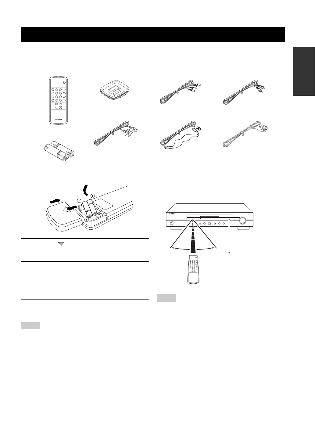
■ Checking the supplied accessories
Check that you received all of the following parts.
Remote control
POWER
DAB/FM/AM
BAND
2
1
3
INFO/TEXT
5
4
6
AUTO SCAN
8
7
9
MEMORY
0
ENTER CLEAR
FUNCTION
FM MODE
TUNING
SELECT
TUNING MODE
Batteries (2)
(AAA, R03, UM-4)
AM loop antenna
Power cable
■ Installing batteries in the remote control
2
3
1
Audio pin cable Digital audio pin
cable
Indoor DAB antenna
Indoor FM antenna
■ Using the remote control
The remote control transmits a directional infrared ray.
Be sure to aim the remote control directly at the remote
control sensor on this unit during operation.
STANDBY
/ON
DIMMER AUTO SCAN MEMORY BAND INFO/TEXT FUNCTION SELECT
DAB/FM/AM FM MODE TUNING MODE
PRESET/TUNING
INTRODUCTION
1 Press the part and slide the battery
compartment cover.
2 Insert the two supplied batteries
(AAA, R03, UM-4) according to the polarity
markings (+ and –) on the inside of the
battery compartment.
3 Slide the battery compartment cover back
until it snaps into place.
Notes
• Change all of the batteries if you notice the operation range of
the remote control decreases.
• Do not use an old battery and a new one together.
• Do not use different types of batteries (such as alkaline and
manganese batteries) together. Read the packaging carefully as
these different types of batteries may have the same shape and
color.
• If the batteries have leaked, dispose of them immediately. Avoid
touching the leaked material or letting it come into contact with
clothing, etc. Clean the battery compartment thoroughly before
installing new batteries.
• Do not throw away batteries with general house waste; dispose
of them correctly in accordance with your local regulations.
Approximately 6 m
30º 30º
Notes
• Do not spill water or other liquids on the remote control.
• Do not drop the remote control.
• Do not leave or store the remote control in the following types
of conditions:
– places of high humidity, such as near a bath
– places of high temperature, such as near a heater or stove
– places of extremely low temperatures
– dusty places
3 En
Controls and functions
Controls and functions
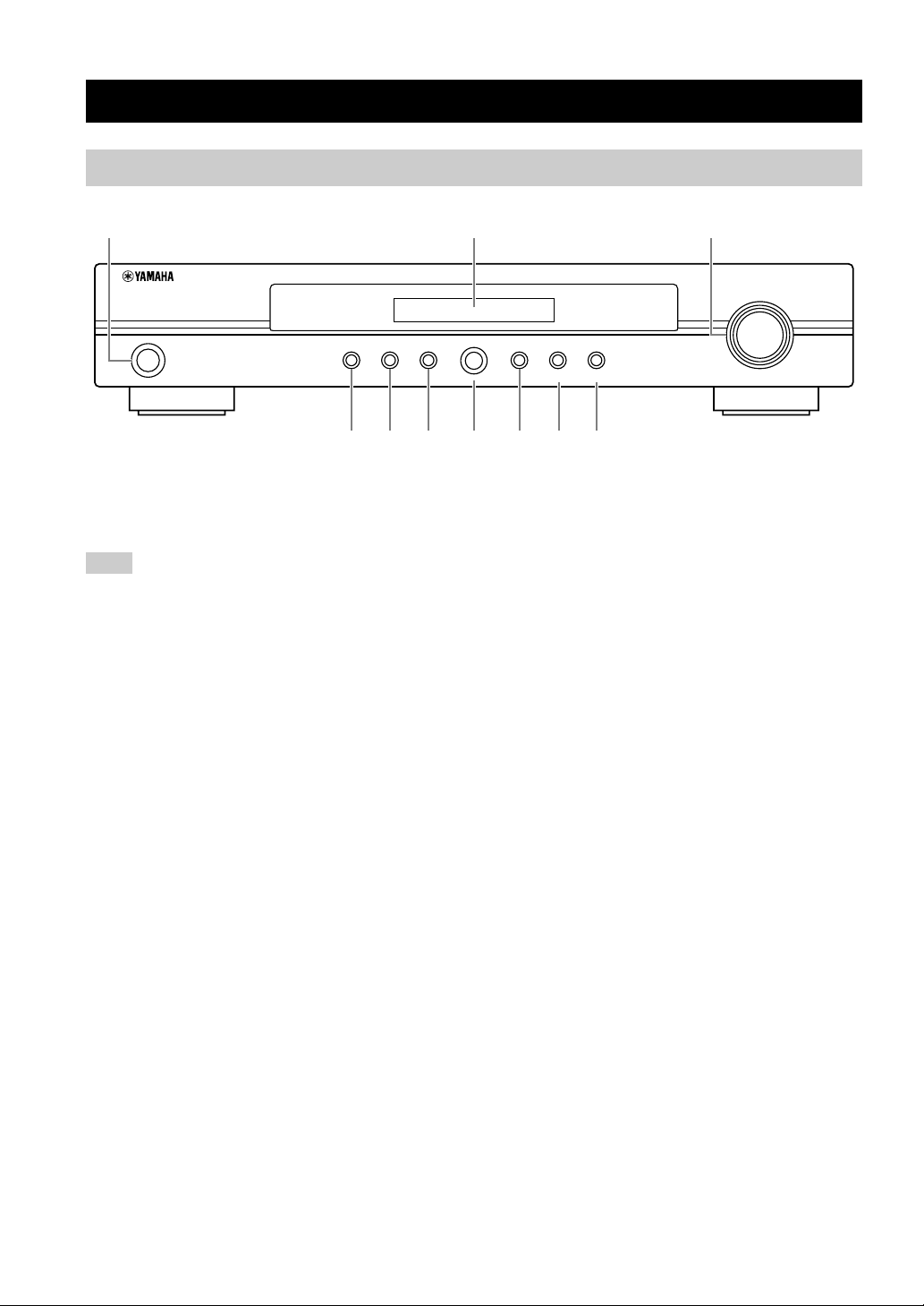
Front panel
123
PRESET/TUNING
STANDBY
/ON
DIMMER AUTO SCAN MEMORY BAND INFO/TEXT FUNCTION SELECT
456 7 890
1 STANDBY/ON
Turns on this unit. Press this button again to set this unit to
the standby mode (see page 9).
Note
In the standby mode, this unit consumes a small amount of power
in order to receive infrared signals from the remote control.
2 Front panel display
Displays information of the currently tuned DAB, FM, or
AM radio station or the operational status (see page 6).
3 PRESET/TUNING
• Selects the preset DAB, FM, or AM stations or services
when this unit is in the preset tuning mode.
• Selects the DAB, FM, or AM stations or services when
this unit is not in the preset tuning mode.
4 DIMMER
Sets the brightness of the front panel display (see page 6).
y
Press and hold DIMMER for 3 seconds to display the firmware
version of this unit. This information is factory use only.
5 AUTO SCAN
Starts the automatic scanning function when this unit is in
the DAB tuning mode (see page 12).
6 MEMORY
Sets this unit to the preset station memory mode when this
unit is in the DAB tuning mode (see page 15) or FM/AM
tuning mode (see pages 21 and 22).
7 BAND
Selects the reception band (DAB, FM, or AM).
DAB/FM/AM FM MODE TUNING MODE
8 INFO/TEXT
Turns on and changes the Radio Data System (see
page 23) or DAB service information (see page 17) in the
front panel display.
9 FUNCTION/FM MODE
• Activates the DAB function setting mode when this
unit is in the DAB tuning mode (see page 13).
• Switches the FM radio wave reception mode (stereo or
monaural) when this unit is in the FM tuning mode (see
page 19).
y
Press and hold FUNCTION/FM MODE for 5 seconds to set this
unit to the initial factory settings (see page 27).
0 SELECT/TUNING MODE
Selects the tuning mode (automatic, manual, or preset
tuning) when this unit is in the FM/AM tuning mode.
4 En

Remote control
Controls and functions
Operating with Yamaha AV amplifier remote controls
You can also operate this unit by using the remote control supplied with your Yamaha AV amplifier (such as
DSP-AX861SE). See page 28 for details.
4 SELECT/TUNING MODE
1
Selects the tuning mode (automatic, manual, or preset
tuning) when this unit is in the FM/AM tuning mode.
5 POWER
POWER
5
Turns on this unit. Press this button again to set this unit to
the standby mode (see page 9).
Note
In the standby mode, this unit consumes a small amount of power
in order to receive infrared signals from the remote control.
6 BAND
Selects the reception band (DAB, FM, or AM).
7 INFO/TEXT
Turns on and changes the Radio Data System or DAB
service information in the front panel display.
8 AUTO SCAN
Starts the automatic scanning function when this unit is in
the DAB tuning mode (see page 11).
9 MEMORY
Sets this unit to the preset station memory mode when this
2
3
4
1
4
7
0
2
5
8
ENTER CLEAR
FUNCTION
FM MODE
TUNING
SELECT
TUNING MODE
DAB/FM/AM
BAND
3
INFO/TEXT
6
AUTO SCAN
9
MEMORY
6
7
8
9
0
A
unit is in the DAB tuning mode (see page 15) or FM/AM
tuning mode (see pages 21 and 22).
INTRODUCTION
1 Infrared transmitter
Outputs infrared controls signals. Aim this transmitter at
the component you want to operate.
2 Numeric buttons, ENTER
Selects the desired preset DAB services (see page 15) or
FM/AM stations (see page 23).
3 FUNCTION/FM MODE
• Activates the DAB function setup mode when this unit
is in the DAB tuning mode (see page 13).
• Switches the FM radio wave reception mode (stereo or
monaural) when this unit is in the FM tuning mode (see
page 19).
0 CLEAR
Deletes the preset memory of the currently selected preset
station number (see pages 16 and 22).
A TUNING
k / n
• Selects the preset DAB, FM, or AM stations or services
when this unit is in the preset tuning mode.
• Selects the DAB, FM, or AM stations or services when
this unit is not in the preset tuning mode.
5 En
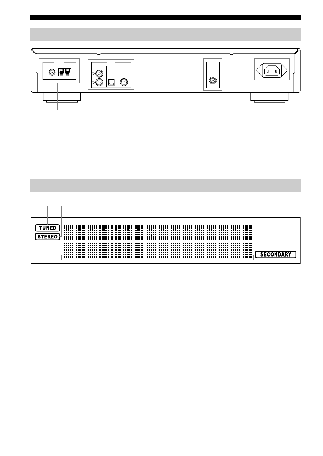
Controls and functions
Rear panel
OUTPUT
DIGITAL (DAB)ANALOGFM GND AM
L
R
12 43
1 FM/AM ANTENNA terminals
See page 8 for connection information.
2 OUTPUT jacks
See page 7 for connection information.
Front panel display
12
ANTENNA AC INANTENNA
COAXIALOPTICAL
DAB
3 DAB ANTENNA terminal
See page 8 for connection information.
4 AC IN
See page 9 for connection information.
1 TUNED indicator
Lights up when this unit is tuned into a station.
2 STEREO indicator
Lights up when this unit is in the stereo playback.
3 Multi-information display
Shows tuning status messages and DAB or Radio Data
System information.
■ Adjusting the brightness of the front
panel display
Press DIMMER on the front panel repeatedly to change
the brightness of the front panel display.
6 En
3
4 SECONDARY indicator
• Lights up when this unit is in the DAB tuning mode
and receiving a secondary service.
• Flashes for 5 seconds when this unit is tuned into the
DAB service which has a secondary service.
4
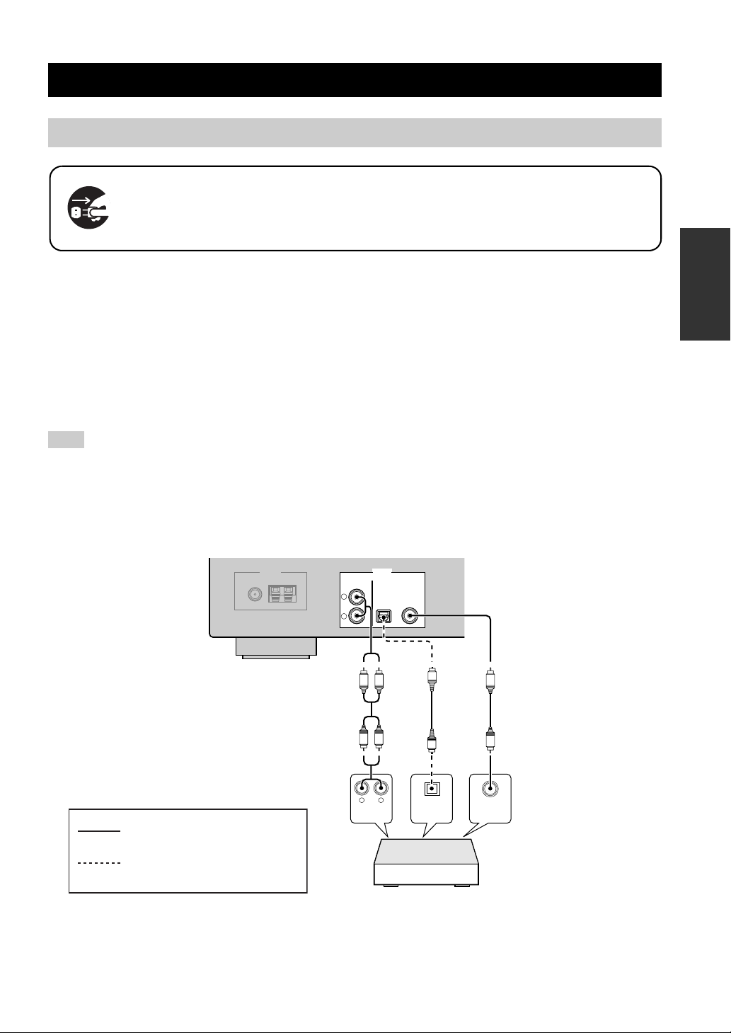
Connections
Connections
Connecting this unit to an amplifier
Make sure that this unit and other components are unplugged from the AC wall outlets.
■ ANALOG OUTPUT jacks
Connect the supplied audio pin cable to the ANALOG OUTPUT jacks of this unit and the analog audio input jacks of
your amplifier as follows.
■ DIGITAL (DAB) OUTPUT jacks
This unit is equipped with the DIGITAL (DAB) OUTPUT jacks (OPTICAL and COAXIAL). These jacks output the
digital audio signals (PCM signals) when this unit is in the DAB tuning mode. Connect the supplied digital audio pin
cable to the DIGITAL (DAB) COAXIAL OUTPUT jack of this unit and the digital coaxial input jack of your amplifier.
You can also use a digital optical audio cable (commercially available) to connect the DIGITAL (DAB) OPTICAL
OUTPUT jack of this unit and the digital OPTICAL input jack of your amplifier.
Note
DAB audio signals are also output at the ANALOG OUTPUT jack of this unit in an analog format. FM or AM audio signals are not
output at the DIGITAL (DAB) OUTPUT jacks.
y
If you want to connect this unit to a Yamaha AV amplifier (such as DSP-AX861SE) via digital audio connection (coaxial or optical), use
the input/output assignment feature of the AV amplifier to assign a coaxial or optical digital audio input jack of your AV amplifier to
“TUNER”. Refer to the owner's manual of your AV amplifier for details.
PREPARATION
75 Ω UNBAL.
Audio pin cable
indicates recommended
connections
indicates alternative connections
L
R
(Supplied)
AUDIO
OUTPUTANTENNA
LR
LR
DIGITAL (DAB)ANALOGFM GND AM
LR
COAXIALOPTICAL
O
O
DIGITAL
INPUT
Amplifier
Optical
cable
C
Digital audio pin cable
(Supplied)
C
COAXIALOPTICAL
DIGITAL
INPUT
7 En
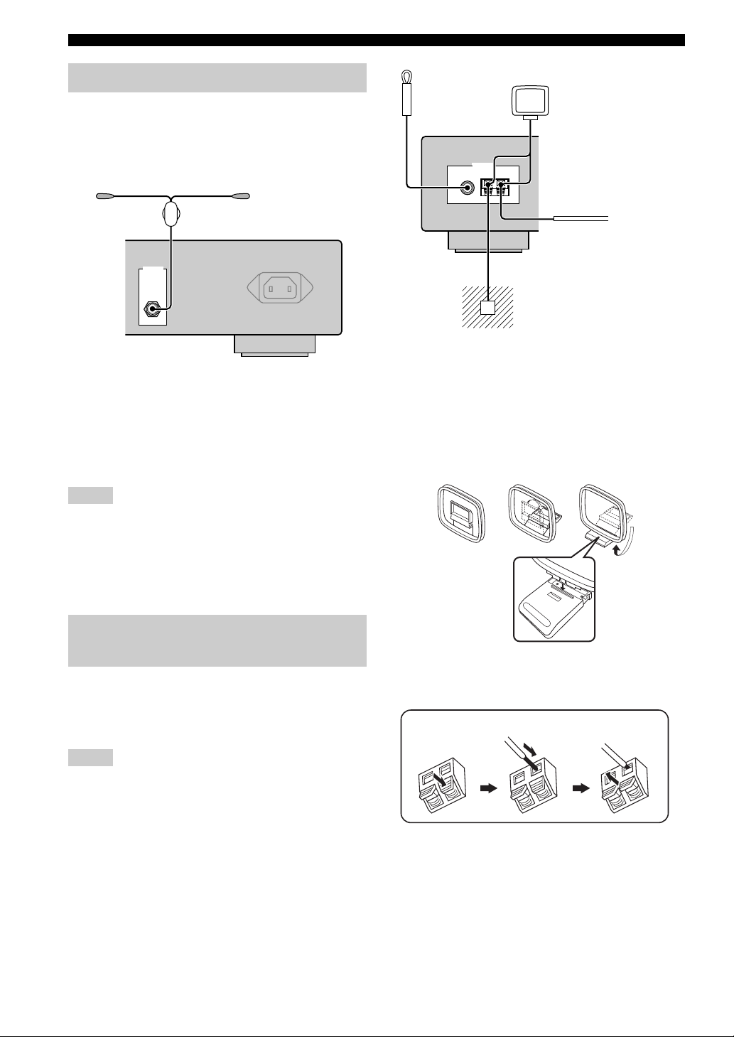
Connections
Connecting the DAB antenna
Connect the supplied indoor DAB antenna to the DAB
antenna terminal on the rear panel and attach the indoor
DAB antenna vertically on the wall.
Indoor DAB antenna
(supplied)
ANTENNA AC IN
DAB
y
It is recommended that you use the tuning aid function (see
page 14) when you set up the indoor DAB antenna in order to
maximize DAB reception capability. After the automatic
scanning operation (see page 11), use “Signal Q” display to check
the signal quality of the currently received DAB service (see
page 18).
Indoor FM
antenna
(supplied)
ANTENNA
FM GND AM
Ground
For maximum safety and minimum
interference, connect the antenna GND
terminal to a good earth ground. A good earth
ground is a metal stake driven into moist earth.
AM loop
antenna
(supplied)
Outdoor AM antenna
Use a 5 to 10 m of vinylcovered wire extended
outdoors from a window.
■ Assembling the supplied AM loop
antenna
Notes
• Be sure to check the DAB coverage in your area in that not all
areas are currently being covered. For a list of nationwide DAB
statuses and worldwide DAB frequencies, check WorldDAB
online at “http://www.worlddab.org/”.
• If the DAB signal is weak, use a commercially available
outdoor DAB antenna for better reception.
Connecting the FM and AM antennas
Both FM and AM indoor antennas are supplied with this
unit. In general, these antennas should provide sufficient
signal strength. Connect each antenna correctly to the
designated terminals.
Notes
• The AM loop antenna should be placed away from this unit.
• A properly installed outdoor antenna provides clearer reception
than an indoor one. If you experience poor reception quality,
install an outdoor antenna. Consult the nearest authorized
Ya ma ha dealer or service center about outdoor antennas.
• The AM loop antenna should always be connected, even if an
outdoor AM antenna is connected to this unit.
• The wire of the AM loop antenna does not have any polarity.
■ Connecting the wire of the AM loop
antenna
Press and hold
Insert
Release
8 En
 Loading...