

Yamaha SW-10 Service manual
SW10
SW10
SERVICE MANUAL
011489
PA
20000125-85000
CONTENTS
SPECIFICATIONS ................................................. 3
DIMENSIONS ............................................................ 3
PANEL LAYOUT ..................................... 4
CIRCUIT BOARD LAYOUT ................. 4
BLOCK DIAGRAM
DISASSEMBLY PROCEDURE ............................. 5
CIRCUIT BOARD ........................................... 6
INSPECTIONS ......................................................... 8/10
OVERALL CIRCUIT DIAGRAM
PARTS LIST
0.29K-5531 Printed in Japan ’99.12
................................ 4
HAMAMATSU, JAPAN
1
SW10
IMPOR TANT NOTICE
This manual has been provided for the use of authorized Yamaha Retailers and their service personnel. It has been assumed
that basic service procedures inherent to the industry, and ÏWre specifically Yamaha Products, are already known and understood by the users, and have therefore not been restated.
WARNING : Failure to follow appropriate service and safety procedures when servicing this product may result in per-
IMPORTANT : This presentation or sale of this manual to any individual or firm does not constitute authorization certifi-
The data provided is belived to be accurate and applicable to the unit(s) indicated on the cover. The research engineering, and
service departments of Yamaha are continually striving to improve Yamaha products. Modifications are, therefore, inevitable
and changes in specification are subject to change without notice or obligation to retrofit. Should any discrepancy appear to
exist, please contact the distributor’s Service Division.
WARNING : Static discharges can destroy expensive components. Discharge any static electricity your body may have
IMPORTANT : Turn the unit OFF during disassembly and parts replacement. Recheck all work before you apply power
sonal injury, destruction of expensive components and failure of the product to perform as specified. For
these reasons, we advise all Yamaha product owners that all service required should be performed by an
authorized Yamaha Retailer or the appointed service representative.
cation, recognition of any applicable technical capabilities, or establish a principal-agent relationship of
any form.
accumulated by grounding yourself to the ground buss in the unit (heavy gauge black wires connect to
this buss.)
to the unit.
WARNING: CHEMICAL CONTENT NOTICE!
The solder used in the production of this product contains LEAD. In addition, other electrical/electronic and/or plastic (Where
applicable) components may also contain traces of chemicals found by the California Health and Welfare Agency (and possibly
other entities) to cause cancer and/or birth defects or other reproductive harm.
DO NOT PLACE SOLDER, ELECTRICAL/ELECTRONIC OR PLASTIC COMPONENTS IN YOUR MOUTH FOR ANY REASON WHAT
SO EVER!
Avoid prolonged, unprotected contact between solder and your skin! When soldering, do not inhale solder fumes or expose
eyes to solder/flux vapor!
If you come in contact with solder or components located inside the enclosure of this product, wash your hands before handling
food.
WARNING
Components having special characteristics are marked and must be replaced with parts having specification equal to those
originally installed.
2
W: 328
H: 459
69407
D: 476
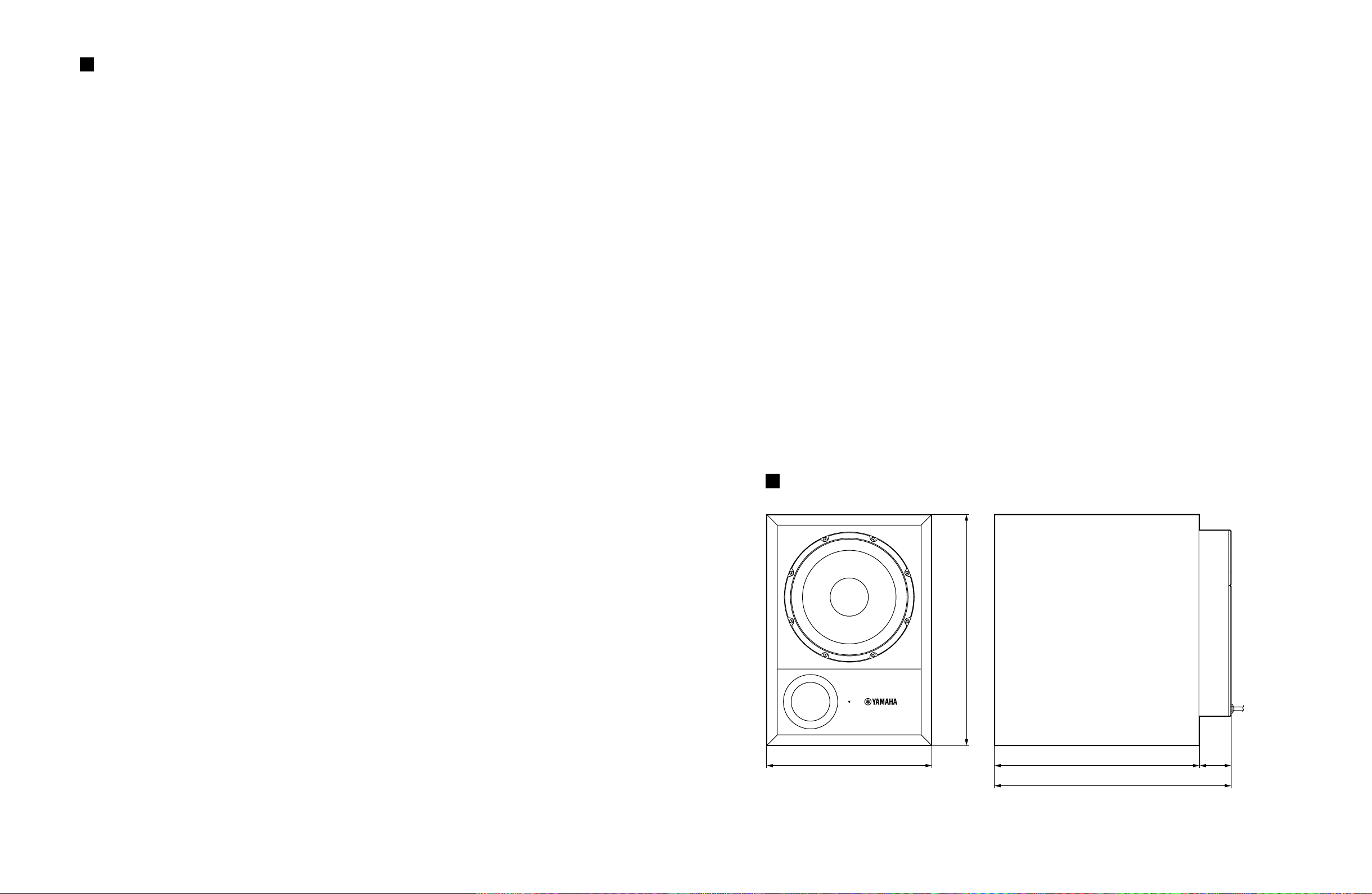
SPECIFICATIONS
General specifications
Type........................................... Bass Reflex Powered Speaker
Frequency Range .......................25–150 Hz (–10 dB)
Sensitivity ..................................–12 dB at Vol. Max (for 100 dB/SPL, 1 m on Axis)
Maximum Output Level ............. 111 dB (1 m on Axis)
Dimensiones (W × H × D).......... 328 × 459 × 476 mm
Weight.......................................26 kg
Speaker unit
Speaker Unit .............................. 25 cm Cone (8Ω, magnetic shielded)
Enclosure ................................... Type: Bass Reflex
Amp.unit
Maximum Output Power............180 W at 100 Hz, THD= 1%, RL= 8Ω
Input Sensitivity/Impedance .......–6 dB to +4 dB/10 kΩ (Input 1, 2, 3)
Hum & Noise............................. ≤–60 dBu (Volume= Min) DIN Audio filter
Signal to Noise Ratio.................. ≥100 dB (IEC-A Weighting)
Controls ..................................... VOL (Level Control)
CUTOFF FREQ. Control: 40–120 Hz (Variable)
PHASE Switch: REV/NORM
POWER Switch: ON/OFF
Connectors ...............................Input 1, 2, 3 (XLR-3-31), Output 1, 2, 3 (XLR-3-32)
Power Indicator/Clip Indicator ... Green/Red LED
Power Requirement....................USA and Canada: AC 120 V, 60 Hz
Europe: AC 230 V, 50 Hz
Others: AC 240 V, 50 Hz
Power Consumption...................160 W
SW10
DIMENSIONS
UNIT: mm
3
SW10
MAIN 5/5
MAIN 4/5
MAIN 3/5
MAIN 2/5
MAIN 1/5
Input
IC101
IC102
IC102
IC101
16 7
2
3
7
6
5
1
2
3
IC104
IC501
IC502
1
Output
Input
2
Output
Input
3
Output
Vol.
P.Amp
P.Amp
Cutoff Freq. Cont.
Low Pass FIL.
Phase SW.
Inverter
Inverter
EQ
N
R
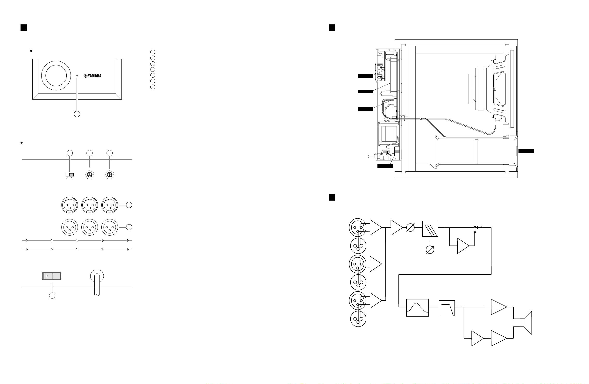
Rear panel
PANEL LAYOUT CIRCUIT BOARD LAYOUT
Front panel
1
Power/Clip indicator
1
PHASE switch
2
CUTOFF FREQ control
3
VOL (Volume) control
4
INPUT jacks 1, 2, and 3
5
OUTPUT jacks 1, 2, and 3
6
POWER switch
7
INPUT
(–6dB~+4dB)
OUTPUT
(THRU)
ON OFF
POWER
7
2 3
80
REV
NORM
PHASE
123
40 120
CUTOFF FREQ.
4
MIN MAX
VOL
5
6
BLOCK DIAGRAM
KEC-92572
4
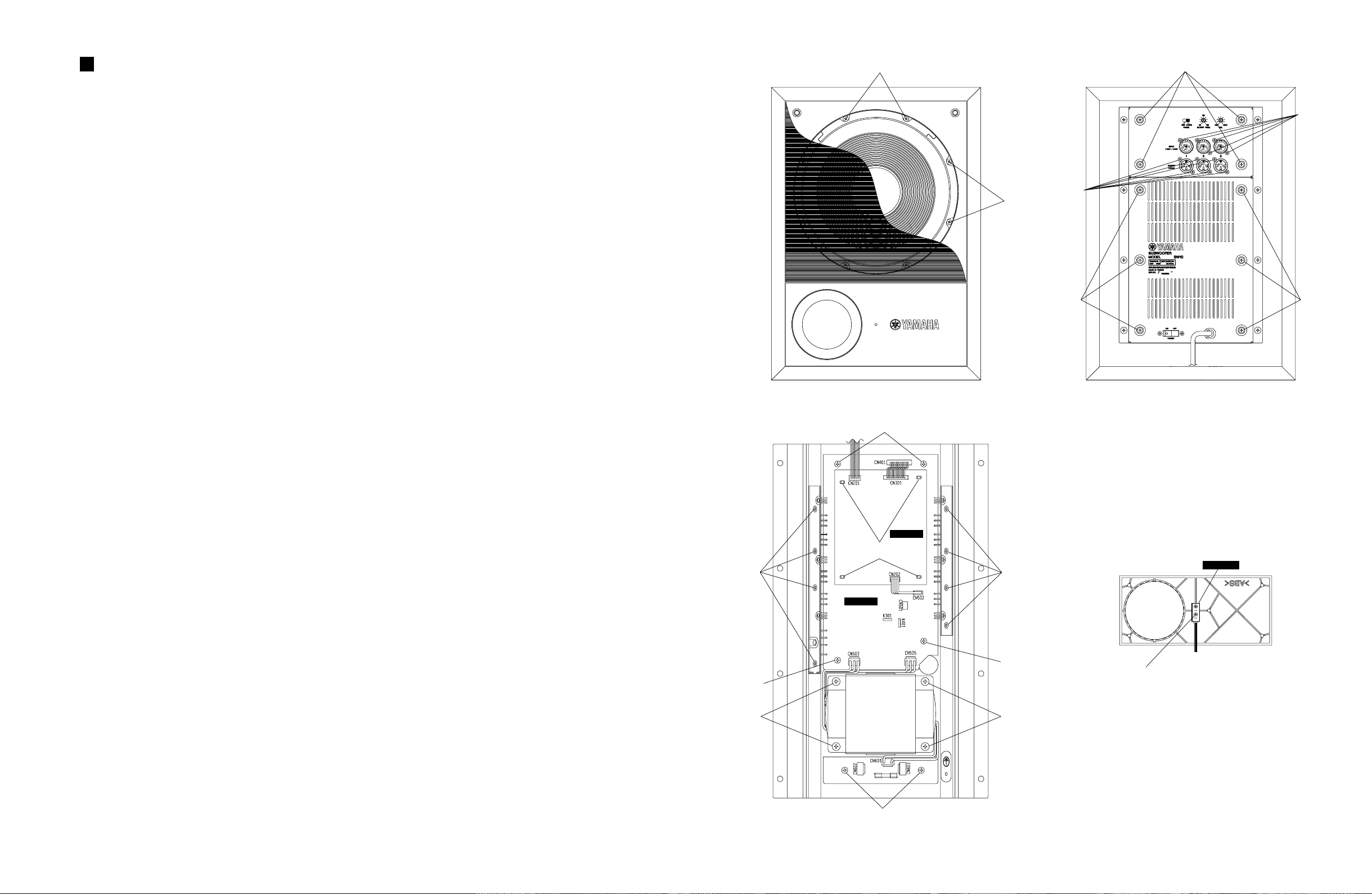
DISASSEMBLY PROCEDURE
[110]
[140]
[140]
[170]
[130]
[130]
[100] [100]
[140A]
[160]
[140B]
[160]
[150]
[140A]
[140]
[150]
Spacer Support
MAIN 5/5
MAIN 2/5
MAIN 3/5
1. Woofer
1-1 Remove the front grille.
1-2. Remove the eight (8) screws marked [140]. The
woofer can then be removed. (Fig.1)
SW10
2. Control Panel
2-1 Remove the four (4) screws marked [170]. The
control panel can then be removed. (Fig.2)
3. Rear Panel
3-1 Remove the six (6) screws marked [100]. The rear
panel can then be removed. (Fig.2)
4. Power T ransformer
4-1 Remove the rear panel. (See procedure 3.)
4-2 Remove the four (4) screws marked [160]. The power
transformer can then be removed. (Fig.3)
5. MAIN 1/5 Circuit Board
5-1 Remove the Control Panel. (See procedure 2.)
5-2 Remove the twelve (12) screws marked [130]. The
MAIN 1/5 circuit board can then be removed.(Fig.2)
6. MAIN 2/5 Circuit Board
6-1 Remove the control panel. (See procedure 2.)
6-2 Remove the rear panel. (See procedure 3.)
6-3 Remove the MAIN 2/5 circuit board from spacer
support. (Fig.3)
7. MAIN 3/5 Circuit Board
7-1 Remove the MAIN 2/5 circuit board. (See procedure 6.)
7-2 Remove the eight (8) screws marked [150]. The TR
press metal A marked [A90 and the TR press metal
B marked [A100] can then be removed.
7-3 Remove the four (4) screws marked [140A]. The
MAIN 3/5 circuit board can then be removed. (Fig.3)
8. MAIN 4/5 Circuit Board
8-1 Remove the rear panel. (See procedure 3.)
8-2 Remove the two (2) screws marked [140B]. The
MAIN 4/5 circuit board can then be removed. (Fig.3)
9. MAIN 5/5 Circuit Board
9-1 Remove the front panel.
9-2 Remove the two (2) screws marked [110]. The MAIN
5/5 circuit board can then be removed. (Fig.4)
Fig.1 Fig.2
Fig.4
Fig.3
5
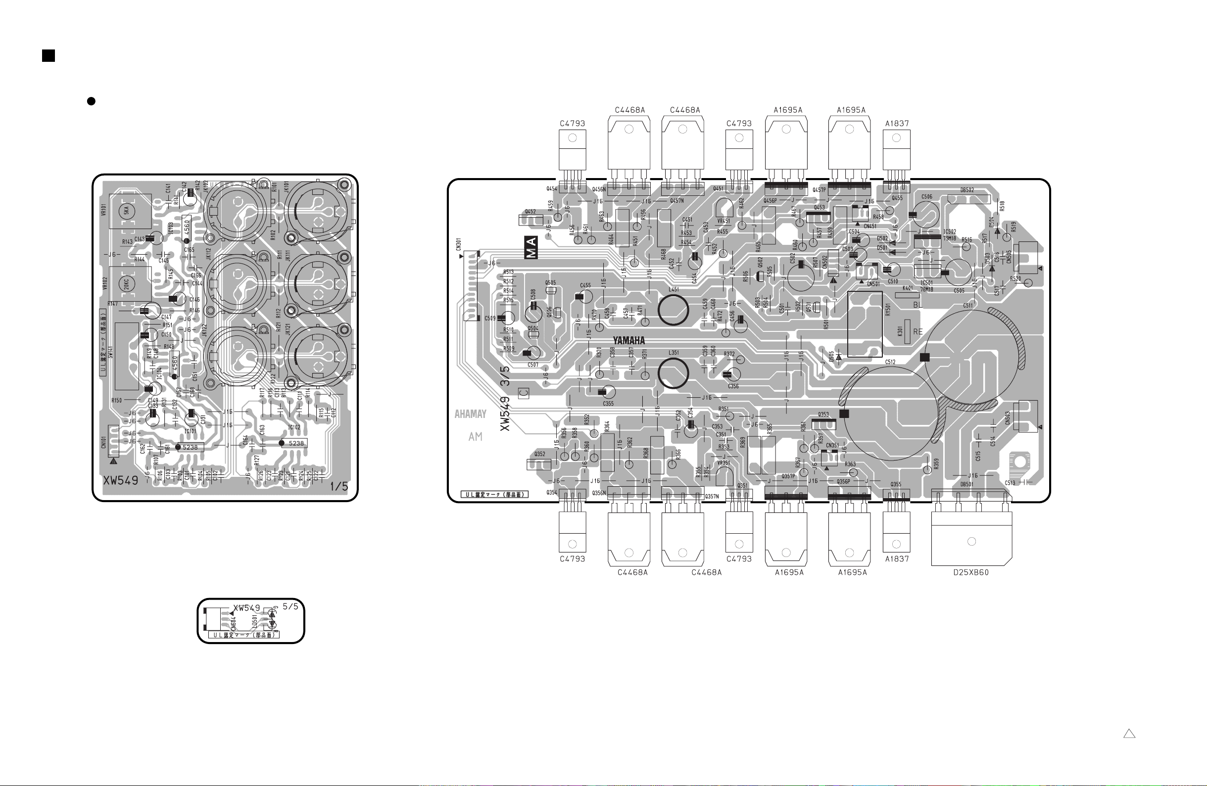
SW10
CN301: to
MA2/5-CN401
CN505: to
Transformer (AC2)
CN502: to
MA2/5-CN202
CN501: to
MA5/5-CN604
CN503: to
Transformer (AC1)
K401,K301: to
SPEAKER
CIRCUIT BOARD
MAIN Circuit Board
VOL.
CUTOFF
FREQ.
PHASE
CN101: to
MA2/5-CN201
MAIN 1/5
INPUT OUTPUT
MAIN 3/5
3
2
1
MAIN 5/5
CN604: to MA3/5
-CN501
Component side
Component side
Component side
Note : See parts list for details of circuit board component parts.
MAIN: 3NA-V434520 2
6
 Loading...