

Page 1
SREV1 Sampling Guide
An Introduction to Impulse-response Sampling with the
SREV1 Sampling Reverberator
Page 2

1
Contents
1 Introduction . . . . . . . . . . . . . . . . . . . . . . . . . . . . . . 2
What is Sound Field Sampling? . . . . . . . . . . . . . . . . . . . . . . . . . . . . . . . . . . . . . 2
What is Convolution? . . . . . . . . . . . . . . . . . . . . . . . . . . . . . . . . . . . . . . . . . . . . . 4
What is an Impulse Response? . . . . . . . . . . . . . . . . . . . . . . . . . . . . . . . . . . . . . . 4
What are Impulse & TSP Signals? . . . . . . . . . . . . . . . . . . . . . . . . . . . . . . . . . . . . 5
What is Averaging? . . . . . . . . . . . . . . . . . . . . . . . . . . . . . . . . . . . . . . . . . . . . . . . . 5
What Equipment is Necessary? . . . . . . . . . . . . . . . . . . . . . . . . . . . . . . . . . . . . . . 6
Is the Quality of the Equipment Important? . . . . . . . . . . . . . . . . . . . . . . . . . . . 6
How about Microphone & Speaker Placement? . . . . . . . . . . . . . . . . . . . . . . . . 6
2 Sampling Tutorial . . . . . . . . . . . . . . . . . . . . . . . . . . 7
Configuring IRSampler . . . . . . . . . . . . . . . . . . . . . . . . . . . . . . . . . . . . . . . . . . . . 7
Checking the Generator Output . . . . . . . . . . . . . . . . . . . . . . . . . . . . . . . . . . . . . 9
Setting Input Levels Automatically . . . . . . . . . . . . . . . . . . . . . . . . . . . . . . . . . . . 9
Actual Sampling . . . . . . . . . . . . . . . . . . . . . . . . . . . . . . . . . . . . . . . . . . . . . . . . . . 9
Using Your Data on the SREV1 . . . . . . . . . . . . . . . . . . . . . . . . . . . . . . . . . . . . . 10
3 Data Editing . . . . . . . . . . . . . . . . . . . . . . . . . . . . . . 11
Fixing the Roar . . . . . . . . . . . . . . . . . . . . . . . . . . . . . . . . . . . . . . . . . . . . . . . . . . . 12
Removing the Delay at the Beginning of the Reverberation . . . . . . . . . . . . . . 13
Deleting the Direct Sound . . . . . . . . . . . . . . . . . . . . . . . . . . . . . . . . . . . . . . . . . . 14
Adjusting the Reverberation Level . . . . . . . . . . . . . . . . . . . . . . . . . . . . . . . . . . . 15
Specifying the Reverb Time & Start Point . . . . . . . . . . . . . . . . . . . . . . . . . . . . . 16
4 Hookup Examples . . . . . . . . . . . . . . . . . . . . . . . . . . 17
MY4-AD/DA I/O System . . . . . . . . . . . . . . . . . . . . . . . . . . . . . . . . . . . . . . . . . . 17
AES/EBU I/O System . . . . . . . . . . . . . . . . . . . . . . . . . . . . . . . . . . . . . . . . . . . . . . 18
Sampling with a Digital Recorder . . . . . . . . . . . . . . . . . . . . . . . . . . . . . . . . . . . . 19
SREV1 Sampling Guide
Page 3

Introduction
1 Introduction
This document provides a basic explanation of sound-field sampling, and a tutorial by
which you can actually sample a sound field and audition it on the SREV1.
For more detailed information on the SREV1, IRSampler, or IREdit, please refer to the
relevant documentation.
What is Sound Field Sampling?
No doubt you are already familiar with the technique of audio sampling, made possible
by the ubiquitous sampler? Well, sound-field sampling is similar, except that instead of
capturing sounds, we’re attempting to capture the unique character of an acoustic
space, such as a concert hall or church. When you sample a sound field with the SREV1,
you are in fact sampling the reverberant characteristics of that acoustic space. The
acquired data can then be loaded into the SREV1 to create a reverb program that reproduces the unique reverberation of the original space.
Let’s take a moment to consider the sounds we hear in an acoustic space such as a hall.
Vocal or instrument sounds (i.e., the audio source) reach the ears of the listener accompanied by the reverberation of that acoustic space. If we substitute a microphone for the
listener’s ears and record the sound, we capture the vocal or instrument sound together
with the reverberation of that acoustic space. Since the reverberation is unique to that
particular space, until now the only way to add it to a vocal or instrument sound was to
actually perform in that space and record the resulting sound. With the introduction of
the SREV1, however, it’s now possible to sample the reverberation characteristics of an
acoustic space and apply them to any audio signal.
2
In conventional recording, changing the location of the singer or instrument (i.e., the
audio source), or the position of the microphone (i.e., the pickup point) affects the
sound that is recorded. You’ve no doubt experienced how the same audio source can
sound different when heard from a first-floor seat and a balcony seat. In addition, different power amplifiers, speakers, microphones, and other equipment can also have an
affect on the recorded sound. These issues also apply to sound-field sampling with the
SREV1. Changing the position of the audio source or the pickup point, for example, or
changing the equipment, all affect the reverberation that is sampled, even in the same
acoustic space. In this respect, sampling a sound field with the SREV1 is similar to normal recording.
Sound-field sampling involves recording the reverberation information that occurs
between an audio source located in the space being sampled and a pickup point. Since
this consists of the information that occurs between these two points, it’s not possible
to capture the reverberation character of an entire acoustic space. By experimenting
and taking a number of samples at various pickup points and sound source positions,
however, you should be able to capture the reverberation character that defines each
and every acoustic space.
SREV1 Sampling Guide
Page 4
What is Sound Field Sampling?
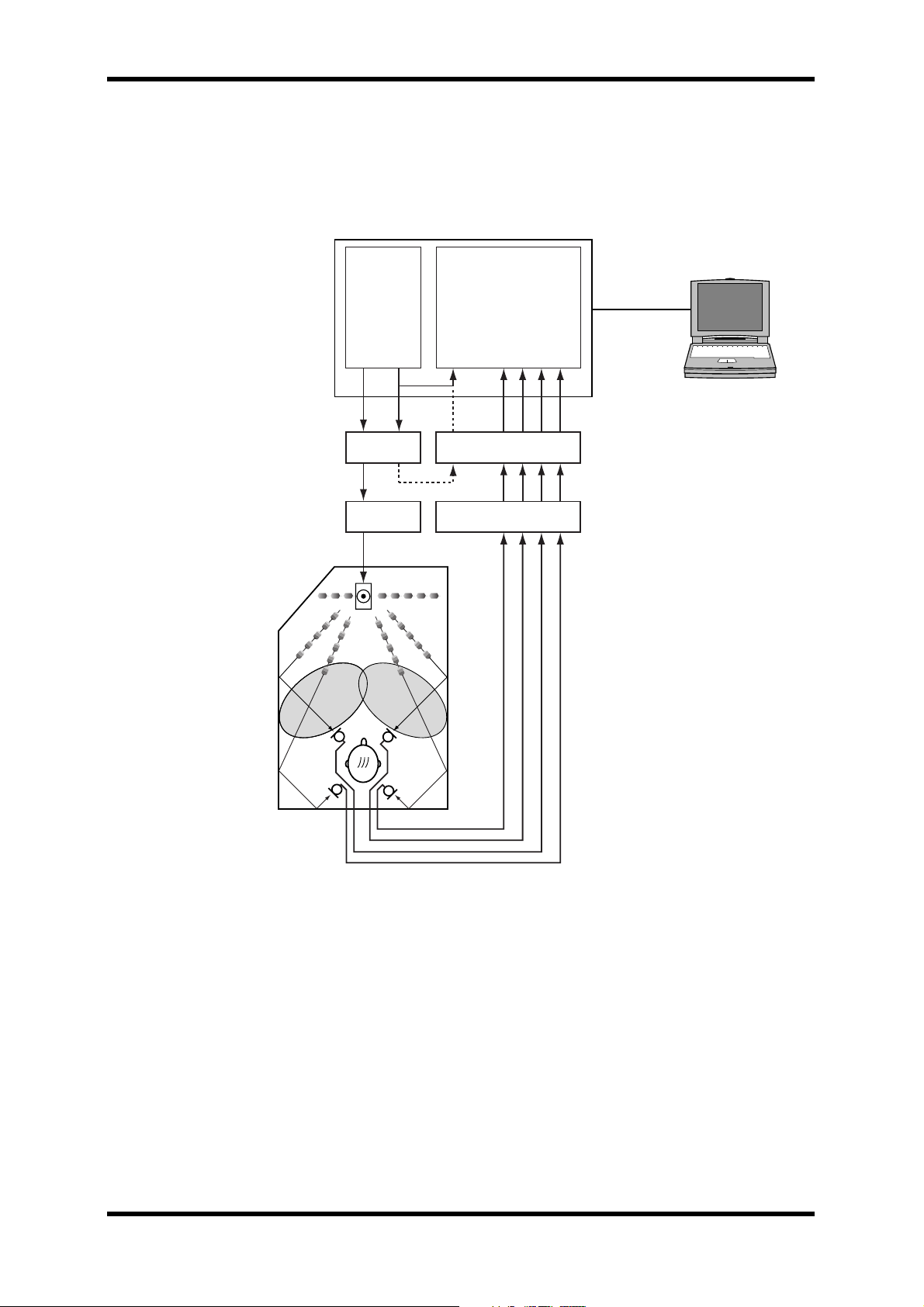
As you can see from the following diagram, sound-field sampling consists of “firing”
SREV1 test pulses into an acoustic space, thereby energizing the reverberation in that
space, which is then picked up by a number of microphones and returned back to the
SREV1 for processing. The acquired data can be saved onto PC Card, edited as necessary using IREdit, and then loaded into the SREV1 to create reverb programs.
SREV1
Generator
Generator output
Trigger output
Internal
D/A A/D
External
Sampler
Trigger input
CH 1 input
CH 2 input
CH 3 input
3
PC running
IRSampler
CH 4 input
Hall
FL FR
RL RR
Power Amp Mic Amp
Firing pulses
SREV1 Sampling Guide
Page 5

What is Convolution?
What is Convolution?
Convolution is a technique for imposing the characteristics of one signal onto another.
What the SREV1 does is to convolve the reverberation characteristics of a previously
sampled acoustic space (i.e., its impulse-response) onto another audio source, producing the same overall sound that would have been heard had the audio source actually
been heard in that acoustic space.
For the technically minded, the following diagram shows the signal flow and formula
for convolution processing.
x(n) x(n-1) x(n-2)
x(n)
h(0) h(1) h(2) h(3)
D D
+
x(n-3)
D
+ +
D+ : 1 sample delay
: multiplier
: adder
x(n-N+3) x(n-N+2) x(n-N+1)
h(N-3)
D
h(N-2)
+
D
h(N-1)
+
4
+
y(n)
N-1
y(n) = h(i) * x(n-i)
i=0
What is an Impulse Response?
Just as a frequency response shows how an audio circuit responds to a range of frequencies, an “impulse-response” shows how an acoustic space responds to an impulse signal.
And since the data acquired by measuring the impulse response of an acoustic space
consists not only of the original test signal, but acoustic information about that space
as well, we can use an impulse-response to measure reverberation.
No doubt you’ve clapped your hands in order to check the reverberation characteristics
of a hall. Well, since a hand clap is audibly similar to the sound of an impulse, this is
akin to hearing an impulse response. What you heard were the reverberation characteristics of that acoustic space, your hands being the audio source, your ears the pickup
point. A handclap is nowhere near as accurate as an impulse signal, so it’s not strictly
the same as what we’re talking about here, but it’s close enough to give you some idea
of what we mean by an impulse response.
Generally speaking, “impulse response” is a response to a linear, time-invariant pulse.
“Linear” meaning undistorted, or in other words, the test signal does not affect the
reverberation characteristics. By “time-invariant” we mean that the reverberation characteristics do not change over time. Conventionally, “time-invariant” is used to mean a
state that does not change, but here we are assuming that the reverberation characteristics do not change from the time the test signal is output to the time sampling is completed.
Impulse signals are ideal for sound-field sampling because they have a very short playback time and a flat frequency response at all frequencies, subject to the limitations of
the recording and playback process.
SREV1 Sampling Guide
Page 6

What are Impulse & TSP Signals?
What are Impulse & TSP Signals?
The SREV1 can generate two types of test signal. First we’ll take a look at the impulse
signal. As explained earlier, an impulse has a very short playback duration and a flat
response at all frequencies. You can acquire impulse-response data by using an impulse
signal, but you can achieve a better S/N performance by using another type of signal,
which we’ll talk about later.
If you listen to the impulse signal, you’ll hear that it has a relatively low sound pressure
(i.e., volume), even when the level meters are virtually at max. And if you turn up your
power amps in an attempt to increase the sound pressure, you run the risk of damaging
your speakers. In order to acquire impulse-response data with a good S/N ratio, you
need the sound pressure (i.e., volume) of the source to be as loud as possible. Obviously,
if your microphones or speakers are distorting, you’ve lost everything.
Now we can introduce the SREV1’s secret weapon—the TSP or “Time Stretched Pulse.”
A TSP has the same flat response as the impulse signal, but differs in that it contains a
sweep of all frequencies, providing a relatively high sound pressure (i.e., volume), as
you can tell by listening. (Be careful with your volume level settings when using TSPs.)
This higher level allows us to capture data with a better S/N ratio than that possible
using an impulse signal.
5
Of course, simply outputting a TSP and miking the result does not produce the necessary data. The SREV1 has to perform various DSP processes to the sampled sound in
order to create the impulse-response data necessary for convolution. But that’s another
story.
What is Averaging?
When sampling in an environment with noise present, such as that of an air conditioning system (i.e., unwanted white noise-type noise), the S/N ratio of the acquired data
will be poor. By using a process called “synchronized summing,” the SREV1 is able to
reduce this noise level by averaging multiple samples, thereby improving the S/N ratio.
As each successive sample is taken, it’s added to the previous sample, thereby increasing
the level of the useful data. Since any background noise is random (i.e., different for
each sample), it increases by only half as much when added.
The number of samples to be taken is set by using the Averaging parameter. When set
to “8,” for example, the pulse signal is output and sampled eight times. Care must be
exercised while multi-sampling is in progress, as any external sounds will have a detrimental affect on the acquired data. If synchronized summing is performed too many
times, the accuracy of the high-frequency detail may be affected.
SREV1 Sampling Guide
Page 7

What Equipment is Necessary?
What Equipment is Necessary?
In order to perform sound-field sampling, you’ll need microphones and microphone
preamps to pick up the sounds, speakers and power amps to output the test pulses, and
the necessary connecting cables. Of course, you’ll need the SREV1, and depending on
the type of I/O being used, you may also require A/D and D/A converters to get signals
in and out of the SREV1. You’ll also need the CD-ROM containing the SREV1 sampling
software, PC Card memory for storing the impulse-response data, a PC running Windows (95, 98, 98SE, 98ME, NT 4.0, or 2000), and a serial cable.
Is the Quality of the Equipment Important?
Since sound-field sampling involves recording the reverberation information that
occurs between an audio source located in the space being sampled and a pickup point,
the sampling equipment (i.e., the microphones, preamps, speakers, power amplifiers,
etc.) does have an effect on the acquired data.
Basically, you need good-quality microphones with a wide frequency response. Those
that you use for hall or studio recording should be adequate. The PA system should have
a wide, flat range and enough power to energize the reverberation you want to capture.
The better the equipment, the more faithful the end results will be.
6
How about Microphone & Speaker Placement?
Typically you want to set up your speakers where the sound source would otherwise be,
and it’s probably worth experimenting in order to obtain the desired results. If you are
sampling a hall, for example, the center of the stage is a good starting place. Also consider the directionality of the speaker so that it corresponds to the directionality of the
instrument whose reverberation effect you are trying to capture. You could use several
speakers to mimic an instrument that distributes sound in various directions.
If you are sampling two channels, start by trying the microphone setup that you usually
employ for stereo recording. If you are sampling four channels, use the same miking
techniques as for 5.1 channel recording.
With your speakers and microphones setup roughly where you think they should go,
play some dry instrument sounds or vocals through the system and adjust the microphone position, direction, height, and the left and right spread. When you hear the
sound you want, you can proceed to the actual sampling.
SREV1 Sampling Guide
Page 8

Sampling Tutorial
2 Sampling Tutorial
Assuming that you’ve set up your speakers and microphones and connected your PC to
the SREV1 (see page 17 for hookup examples), you’re now ready to “fire” a few pulses
and “grab” some samples.
We’re assuming that SREV1 I/O is being taken care of by MY4-AD and MY4-DA cards.
If you’re using external A/D and D/A converters, your IRSampler I/O assignments will
need to be a little different to those specified later.
Before we start, turn on the SREV1, insert the CD-ROM containing the SREV1 sampling software, and insert a PC Card memory card. (The RC-SREV1 Remote Controller
is not necessary for sampling.) Finally, start the IRSampler program.
Configuring IRSampler
COM Port (COM Port dialog box)
The COM Port dialog box appears the first time IRSampler is started and is used to
select the PC COM port to which the SREV1 is connected. The selected COM port is
used automatically the next time IRSampler is started, but can be changed at any time
by choosing COM Port from the Setup menu. Choose COM1 or COM2 as appropriate.
7
Word Clock Source (Word Clock toolbar)
Set the Word Clock source to “INTERNAL” (FS will be “48 kHz”)
Channel Mode (Word Clock toolbar)
Set the Channel mode as appropriate (e.g., 1ch, 2ch, 4ch)
Pulse Generator (Generator/Trigger window)
Set the Generator Source to “TSP64k”
Set the Loop Interval to “5000” msec (i.e., 240000 samples)
The Loop Interval must be long enough so that the reverberation energized by each
pulse has time to fade away completely before the next pulse is fired. If the next pulse is
fired while the previous reverberation can still be heard, the acquired data will be unusable, especially when using TSP signals. Obviously, environments that produce longer
reverberation require longer loop intervals.
Start Trigger (Generator/Trigger window)
Set the Trigger Source to “Internal”
Set the Trigger Threshold to “50%”
Set the Trigger Slope to “ABS”
SREV1 Sampling Guide
Page 9

Configuring IRSampler
Sampler (Generator/Trigger window)
Set Averaging to “8”
Set the Sampling Time to “4500” msec (i.e., 216000 samples)
Generator Output Assign (Generator/Trigger window)
Assign the Generator Output to “Slot2-1”
Trigger Output Assign (Generator/Trigger window)
Assign the Trigger Output to “Slot2-2”
Input Assign (Generator/Trigger window)
Assign the Sampler Inputs as follows:
Channel 1: Slot 1-1
Channel 2: Slot 1-2
Channel 3: Slot 1-3
8
Channel 4: Slot 1-4
Input Levels (Main window)
Set the Sampler Input level faders as follows:
Channel 1: 0.0 dB
Channel 2: 0.0 dB
Channel 3: 0.0 dB
Channel 4: 0.0 dB
At this point, try a microphone test and check the input level meters to verify that the
microphones are working properly. If no signals are present on the meters, check the
connections and input assignments.
Generator Output Level (Main window)
Set the Generator Output level fader to “0.0 dB”
SREV1 Sampling Guide
Page 10

Checking the Generator Output
Checking the Generator Output
We’re now ready to check the generator output. Click the Start Generator button on the
Sampling Control toolbar and verify that the test signal is being output properly from
the speaker system. If it’s not, check the connections and generator output assignment.
Starting with the level set low, gradually increase the power amp’s input attenuators so
that the pulses can be clearly heard. (Setting the Generator mode to loop is convenient
for outputting pulses continuously while making this adjustment.) The pulse signal
should be loud enough to fully energize the reverberant characteristics of the environment you are sampling, but without distortion.
Setting Input Levels Automatically
The Level Adjust function offers a convenient way to set input levels automatically.
Click the Adjust button on the main window, and when the Level Adjust window
appears, click the Start button. The SREV1 outputs several pulses and IRSampler calculates the optimum input levels. A progress report appears in the Status box.
In addition to setting the input level faders, the Level Adjust function automatically calculates and sets the CNV (Convolution) Bit Shift parameter, which is used to normalize
the acquired data to an optimum level for use with the SREV1.
9
Actual Sampling
Sampling
To begin sampling, click the Start Sampling button on the Sampling Control toolbar.
Sampling is performed in accordance with the parameter settings made earlier. When
sampling is complete, the Waveform window appears automatically, displaying waveforms of the acquired data.
Saving the Acquired Data
If you are happy with the acquired data, enter titles, and click the Save As button for
each waveform. (The title is saved in the file header.) Enter a filename in the Save As dialog box and click Save. By default, data is saved in the “irdata” (c:/yamaha/irmec/irdata)
folder on the PC Card in TM4 format. (A “.tm4” file extension is added automatically.)
Taking Several Samples
While your sampling system is setup, it’s a good idea to take several samples at various
microphone and speaker placements or with different IRSampler settings. Once back
in the studio you can easily delete the unwanted data. Going back to a location and setting up all your gear again, however, may not be so easy.
SREV1 Sampling Guide
Page 11

Using Your Data on the SREV1
Using Your Data on the SREV1
Put your data in the right folder
1
The SREV1 can only load impulse-response data stored in the “c:\yamaha\srev\data”
folder of the PC Card. So the first thing you need to do is to make a new folder called
“data” in “x:\yamaha\srev\” and copy your acquired data into it, something you can do
on your PC. (Note that “x” refers to the letter assigned to your PC Card while it’s
inserted in your PC.)
2
Insert the PC card into the SREV1
Insert the PC Card into the SREV1’s MEMORY CARD slot.
3
Load your data
On the RC-SREV1, go to the Rev page, select the DATA LOAD button, and press
[ENTER] to access the Data Load page. Next, select the PCMCIA button and press the
[ENTER] button. Your impulse-response data should appear in the list of files.
Use the DATA wheel or the [-1/DEC] and [+1/INC] buttons to select your file in the
list. And then select the button of the channel to which you want to load the data. Click
the [ENTER] button to load the data. Repeat this procedure to load data for the other
channels.
10
4
Audition your reverb data
Now you can listen to the reverb generated from your own samples.
Adjust the EQ
5
On the Data Load page, select the BACK button and press the [ENTER] button to
return to the Rev page. Go to the EQ pages and try adjusting the pre- and post-EQ
parameters.
Save your program
6
If you’re happy with your new reverb program, go to the Program page and save it to
PC Card now!
SREV1 Sampling Guide
 Loading...