

Yamaha SR125 Owner's Manual

OWNER’S MANUAL
SR125
3MW-28199-E3


EAU00001
INTRODUCTION
Welcome to the Yamaha world of motorcycling!
As the owner of a SR125, you are benefiting from Yamaha’s vast experience in and
newest technology for the design and the manufacture of high-quality products,
which have earned Yamaha a reputation for dependability.
Please take the time to read this manual thoroughly, so as to enjoy all your SR125’s
advantages. The owner’s manual does not only instruct you in how to operate,
inspect and maintain your motorcycle, but also in how to safeguard yourself and others from trouble and injury.
In addition, the many tips given in this manual will help to keep your motorcycle in
the best possible condition. If you have any further questions, do not hesitate to contact your Yamaha dealer.
The Yamaha team wishes you many safe and pleasant rides. So, remember to put
safety first!
IMPORTANT MANUAL INFORMATION
Particularly important information is distinguished in this manual by the following notations:
The Safety Alert Symbol means ATTENTION! BECOME ALERT! YOUR SAFETY IS
INVOLVED!
EAU00005
WARNING
CAUTION:
NOTE:
Failure to follow WARNING instructions could result in severe injury or death to the
motorcycle operator, a bystander or a person inspecting or repairing the motorcycle.
A CAUTION indicates special precautions that must be taken to avoid damage to the
motorcycle.
A NOTE provides key information to make procedures easier or clearer.
NOTE:
@
This manual should be considered a permanent part of this motorcycle and should remain
●
with it even if the motorcycle is subsequently sold.
Yamaha continually seeks advancements in product design and quality. Therefore, while
●
this manual contains the most current product information available at the time of printing,
there may be minor discrepancies between your motorcycle and this manual. If there is any
question concerning this manual, please consult your Yamaha dealer.
@
IMPORTANT MANUAL INFORMATION
EW000002
WARNING
@
PLEASE READ THIS MANUAL CAREFULLY AND COMPLETELY BEFORE OPERATING
THIS MOTORCYCLE.
@
IMPORTANT MANUAL INFORMATION
SR125
OWNER’S MANUAL
© 2001 by Yamaha Motor Co., Ltd.
1st Edition, January 2001
All rights reserved.
Any reprinting or unauthorized use
without the written permission of
Yamaha Motor Co., Ltd.
is expressly prohibited.
Printed in Japan.
EAU03337
EAU00009
TABLE OF CONTENTS
GIVE SAFETY THE RIGHT OF WAY..................1-1
1
DESCRIPTION ....................................................2-1
2
Left view.............................................................2-1
Right view...........................................................2-2
Controls/Instruments..........................................2-3
INSTRUMENT AND CONTROL FUNCTIONS....3-1
3
Main switch/steering lock ...................................3-1
Indicator lights....................................................3-2
Speedometer......................................................3-2
Handlebar switches............................................3-2
Clutch lever........................................................3-4
Shift pedal..........................................................3-4
Front brake lever................................................3-4
Rear brake pedal................................................3-5
Fuel tank cap......................................................3-5
Fuel....................................................................3-6
Fuel cock............................................................3-6
Starter (choke) knob...........................................3-7
Seat....................................................................3-8
Helmet holder.....................................................3-8
Rear shock absorber adjustment.......................3-9
Sidestand...........................................................3-9
Sidestand/clutch switch operation check .........3-10
PRE-OPERATION CHECKS.................... ... ........4-1
4
Pre-operation check list......................................4-1
OPERATION AND IMPORTANT RIDING
5
POINTS................................................................5-1
Starting the engine.............................................5-1
Starting a warm engine ......................................5-3
Shifting...............................................................5-4
Recommended shift points
(for Switzerland only)..................................... .5-4
Tips for reducing fuel consumption....................5-5
Engine break-in............. ... ..................................5 -5
Parking...............................................................5-6
PERIODIC MAINTENANCE AND MINOR
6
REPAIR................................................................6-1
Tool kit................................................................6-1
Periodic maintenance and lubrication chart.. .... .6-2
Panel removal and installation ......... .... ... ...........6-5
Panels A and B .................................... ... ... ... .....6-5
Spark plug..........................................................6-6
Engine oil ................................... ... ... ..................6-8
Air filter............................................................. 6 - 10
Carburetor adjustment .....................................6-11
Idle speed adjustment......................................6-11
TABLE OF CONTENTS
Throttle cable free play adjustment..................6-12
Cam chain adjustment................... ... .... ... ... .....6-12
Valve clearance adjustment.............................6-13
Tires............................ ... ... ...............................6-13
Wheels........................ ... ... ... .... ... ... ..................6-15
Clutch lever free play adjustment.....................6-16
Front brake lever free play adjustment............6-16
Rear brake pedal height and free play
adjustment....................................................6-17
Brake light switch adjustment ..........................6-18
Checking the front brake pads and
rear brake shoes ..........................................6-19
Inspecting the brake fluid level.........................6-20
Brake fluid replacement ...................................6-20
Drive chain slack check ...................................6-21
Drive chain slack adjustment ...........................6-22
Drive chain lubrication................. ... ... .... ... ... .....6-23
Cable inspection and lubrication......................6-23
Throttle cable and grip lubrication....................6-23
Brake and shift pedal lubrication......................6-24
Brake and clutch lever lubrication....................6-24
Center and sidestand lubrication .....................6-24
Front fork inspection ........................................6-25
Steering inspection ..........................................6-26
Wheel bearings................................................6-26
Battery..............................................................6-26
Fuse replacement............................................6-28
Headlight bulb replacement ........... ... ...............6-29
Turn signal and tail/brake light bulb
replacement..................................................6-30
Front wheel removal ........................................6-30
Front wheel installation ....................................6-31
Rear wheel removal..... ... ... ..............................6-32
Rear wheel installation.................................... .6-33
Troubleshooting................. .... ... .......................6-33
Troubleshooting chart ......................................6-34
MOTORCYCLE CARE AND STORAGE.............7-1
7
Care............................. ......................................7-1
Storage ..............................................................7-4
SPECIFICATIONS...............................................8-1
8
Specifications.....................................................8-1
How to use the conversion table........................8-5
CONSUMER INFORMATION..............................9-1
9
Identification number records.............................9-1
Key identification number....... ... ... ... ... .... ... .........9-1
Vehicle identification number.............................9-1
Model label.........................................................9-2
EAU00021
1-
GIVE SAFETY THE RIGHT OF WAY
Motorcycles are fascinating vehicles, which can give you an unsurpassed feeling of power and
freedom. However, they also impose cer tain lim its, whic h you must acce pt; ev en th e best motorc ycle
does not ignore the laws of physics.
Regular care and maintenance are essential for preserving your motorcycle’s value and operating
condition. Moreover, what is true for the motorcycle is also true for the rider: good performance
depends on being in good shape. Riding under the influence of medication, drugs and alcohol is, of
course, out of the question. Motorcycle rid ers - mo re th an ca r d rivers - must always be at t heir ment al
and physical best. Under the influence of even small amounts of alcohol, there is a tendency to take
dangerous risks.
Protective clothing is as essential for the motorcycle rider as seat belts are for car drivers and
passengers. Always wear a complete motorcycle suit (whether made of leather or tear-resistant
synthetic materials with protectors), sturdy boots, motorcycle gloves and a properly fitting helmet.
Optimum protective wear, however, should not encourage carelessness. Though full-coverage
helmets and suits, in particular, create an illusion of total safety and protection, motorcyclists will
always be vulnerable. Riders who lack critical self-c ontrol ru n the risk of go ing too fas t and are apt to
take chances. This is even more dangerous in wet weather. The good motorcyclist rides safely,
predictably and defensively - avoiding all dangers, including those caused by others.
Enjoy your ride!
1
1-1
2-
DESCRIPTION
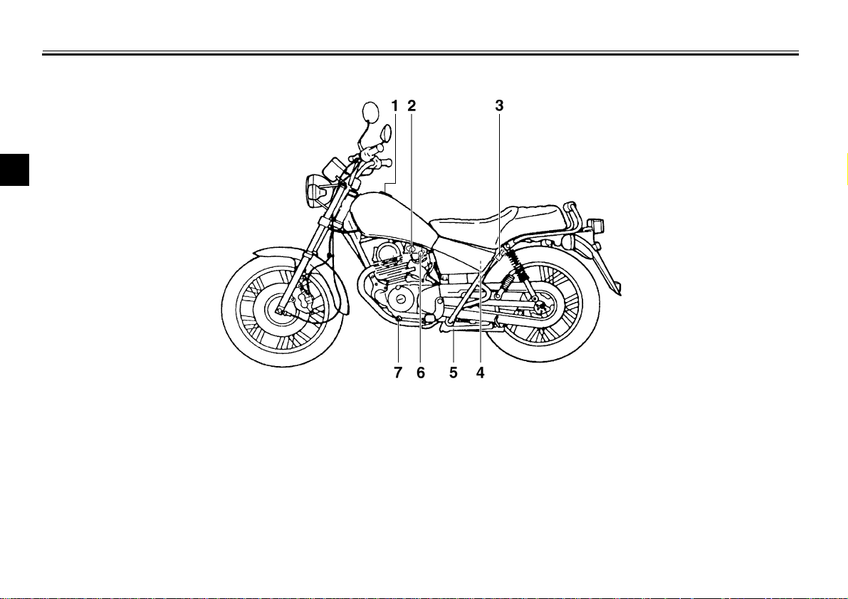
Left view
2
EAU00026
1.Fuel tank cap (page 3-5)
2.Fuel cock (page 3-6)
3.Helmet holder (page 3-8)
4.Fuse box (page 6-28)
5.Sidestand (page 3-9)
6.Starter (choke) knob (page 3-7)
7.Shift pedal (page 3-4)
2-1
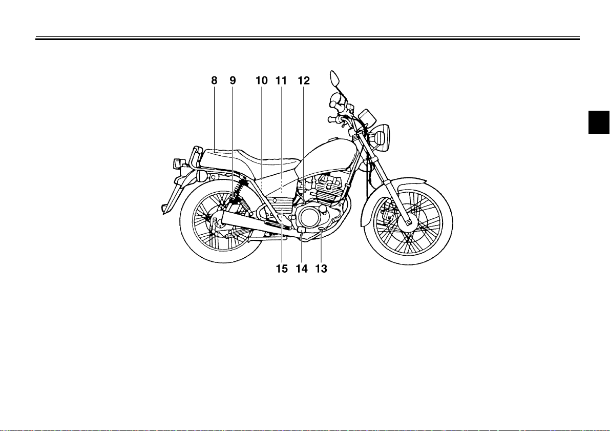
Right view
DESCRIPTION
2
8.Seat (page 3-8)
9.Rear shock absorber spring
preload adjusting ring (page 3-9)
10.Tool kit (page 6-1)
11.Air filter (page 6-10)
12.Engine oil filler cap
13.Rear brake pedal (page 3-5)
14.Footrest
15.Battery (page 6-26)
2-2
DESCRIPTION
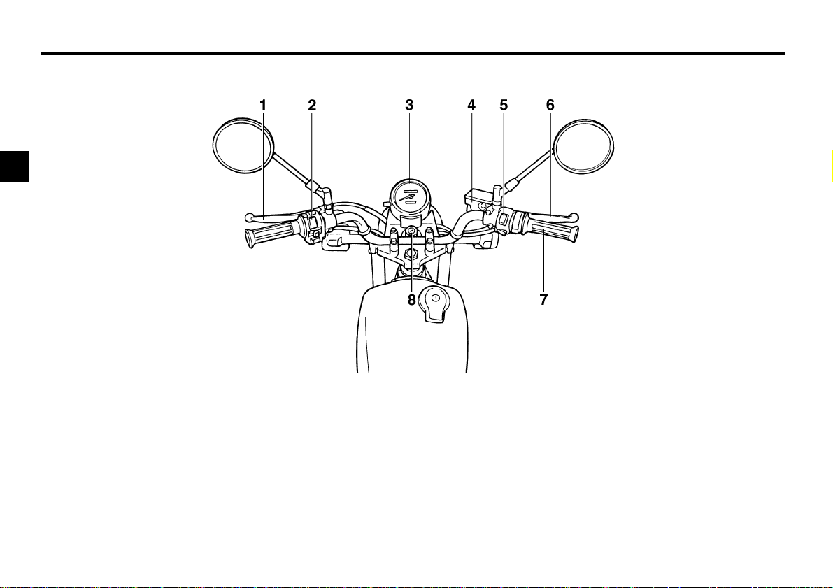
Controls/Instruments
2
1.Clutch lever (page 3-4)
2.Left handlebar switches (page 3-2)
3.Speedometer (page 3-2)
4.Front brake fluid reservoir (page 6-20)
5.Right handlebar switches (page 3-3)
6.Front brake lever (page 3-4)
7.Throttle grip (page 6-12)
8.Main switch/steering lock (page 3-1)
2-3
EAU00027
WARNING
EAU00029*
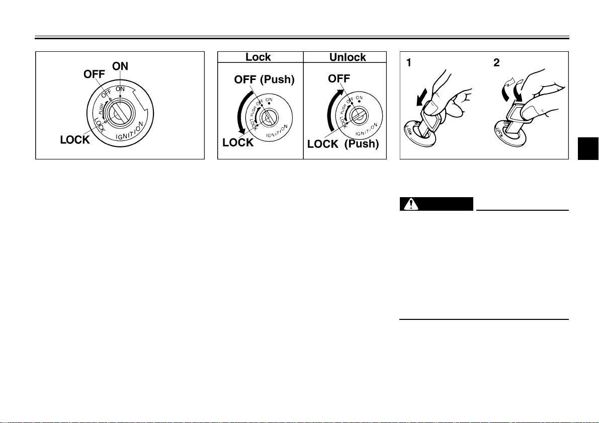
Main switch/steering lock
The main switch controls the ignition
and lighting systems. Its operation is
described below.
EAU00036
ON
Electrical circuits are switched on. The
engine can be started. The key cannot
be removed in this position.
EAU00038
OFF
All electrical circuits are switched off.
The key can be removed in this position.
3-
INSTRUMENT AND CONTROL FUNCTIONS
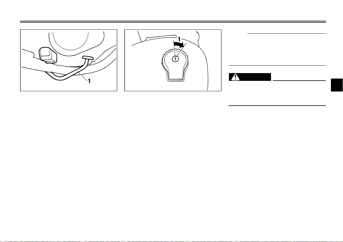
1. Push
EAU00040
2. Turn
LOCK
The steering is locked in this position
and all electrical circuits are switched
off. The key can be removed in this position.
To lock the steering, turn the handlebars all the way to the left. While pushing the key into the main switch, turn it
from “OFF” to “LOCK” and remove it.
To release the lock, turn the key to
“OFF” while pushing.
@
Never turn the key to “OFF” or
“LOCK” when the motorcycle is
moving. The electrical circuits will
be switched off which may result in
loss of control or an accident. Be
sure the motorcycle is stopped before turning the key to “OFF” or
“LOCK”.
@
3
EW000016
3-1

INSTRUMENT AND CONTROL FUNCTIONS
3
1. Neutral indicator light “ ”
2. Turn indicator light “ ”
3. High beam indicator light “ ”
EAU00056
Indicator lights
EAU00061
Neutral indicator light “ ”
This indicator comes on when the
transmission is in neutral.
EAU00057
Turn indicator light “ ”
This indicator flashes when the turn
switch is moved to the left or right.
EAU00063
High beam indicator light “ ”
This indicator comes on when the
headlight high beam is used.
1. Reset knob
2. Tripmeter
3. Odometer
4. Speedometer
EAU00095*
Speedometer
The speedometer shows riding speed.
This speedometer is equipped with an
odometer and tripmeter. The tripmeter
can be reset to “0” with the reset knob.
Use the tripmeter to estimate how far
you can ride on a tank of fuel. This information will enable you to plan fuel
stops in the future.
3-2
1. Lights switch
2. Dimmer switch
3. Turn signal switch
4. Horn switch “ ”
EAU00118
Handlebar switches
EAU00134
Lights switch
Turning the light switch to “ ”,
turns on the auxiliary light, meter lights
and taillight. Turning the light switch to
“ ” turns the headlight on also.
EAU00121
Dimmer switch
Turn the switch to “ ” for the high
beam and to “ ” for the low beam.
INSTRUMENT AND CONTROL FUNCTIONS
CAUTION:
EAU00127
Turn signal switch
To signal a right-hand turn, push the
switch to “ ”. To signal a left-hand
turn, push the switch to “ ”. Once the
switch is released it will return to the
center position. To cancel the signal,
push the switch in after it has returned
to the center position.
EAU00129
Horn switch “ ”
Press the switch to sound the horn.
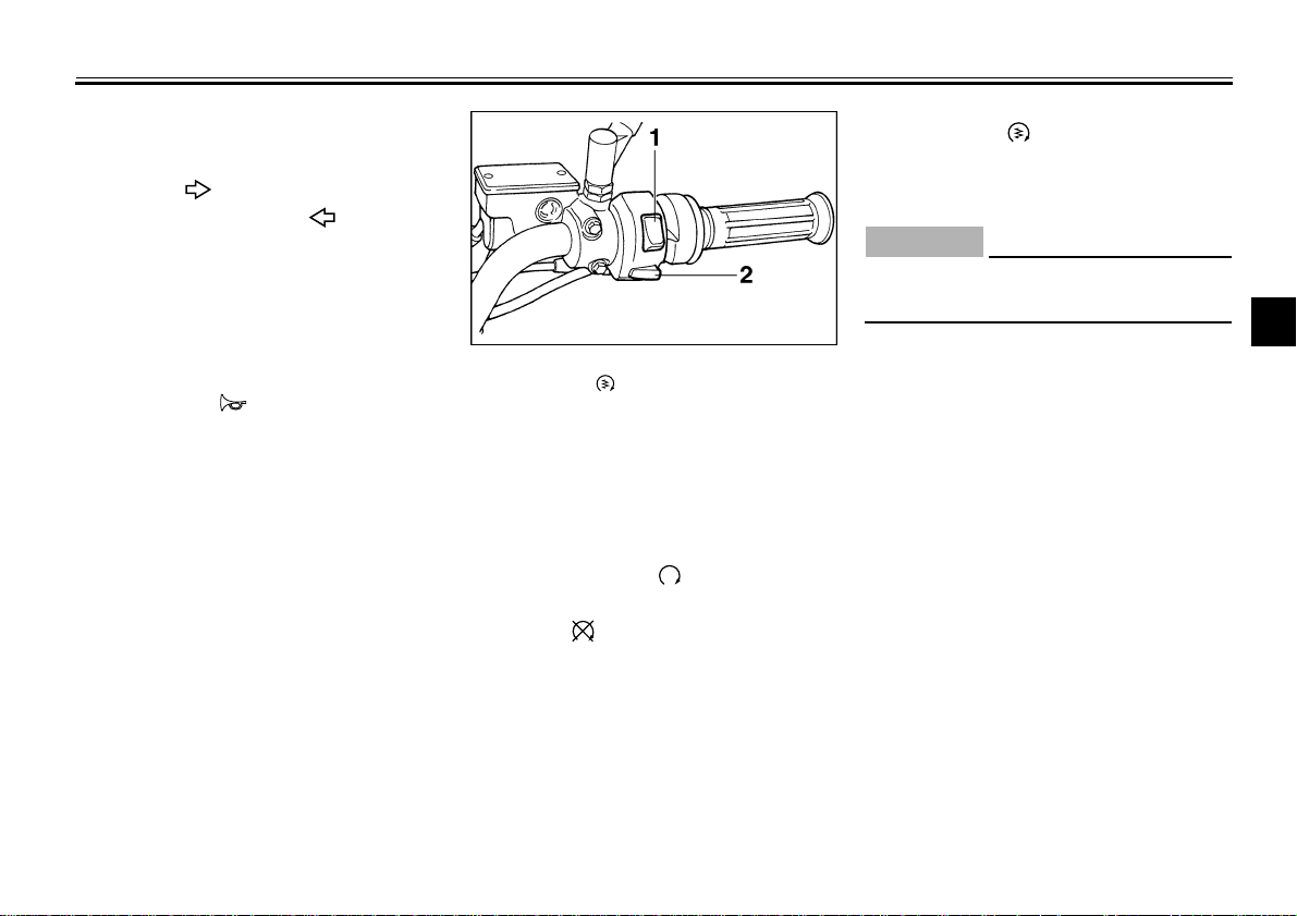
1. Engine stop switch
2. Start switch “ ”
EAU00138
Engine stop switch
The engine stop switch is a safety device for use in an emergency such as
when the motorcycle overturns or if
trouble occurs in the throttle system.
Turn the switch to “ ” to start the engine. In case of emergency, turn the
switch to “ ” to stop the engine.
EAU00143
Start switch “ ”
The starter motor cranks the engine
when pushing the start switch.
EC000005
@
See starting instructions prior to
starting the engine.
@
3
3-3
INSTRUMENT AND CONTROL FUNCTIONS
3
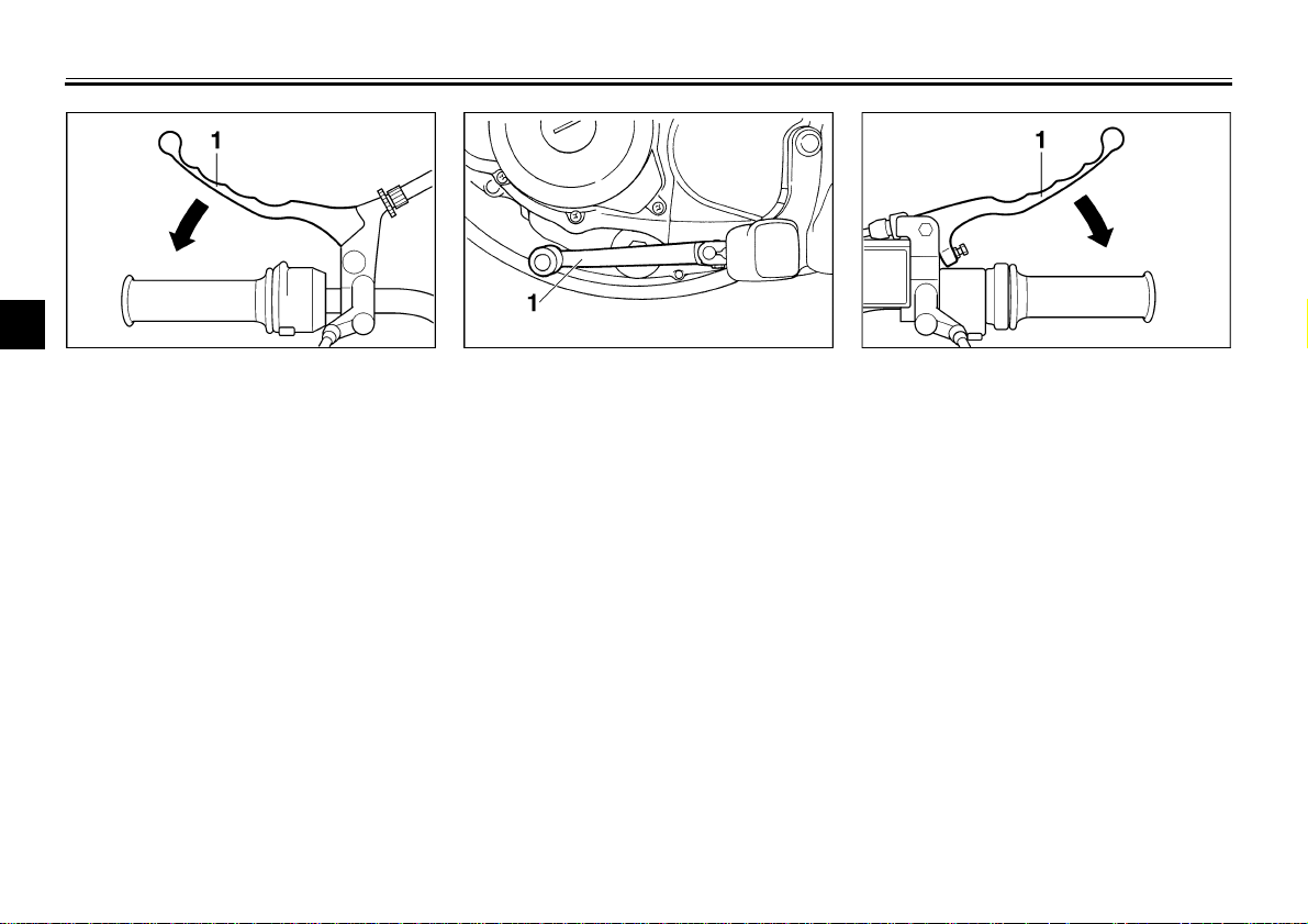
1. Clutch lever 1. Shift pedal 1. Front brake lever
EAU00152
Clutch lever
The clutch lever is located on the left
handlebar, and the ignition circuit cutoff system is incorporated in the clutch
lever holder. Pull the clutch lever to the
handlebar to disengage the clutch, and
release the lever to engage the clutch.
The lever should be pulled rapidly and
released slowly for smooth clutch operation. (Refer to the engine starting procedures for a description of the ignition
circuit cut-off system.)
Shift pedal
This motorcycle is equipped with a constant-mesh 5-speed transmission.
The shift pedal is located on the left
side of the engine and is used in combination with the clutch when shifting.
EAU00157
Front brake lever
The front brake lever is located on the
right handlebar. Pull it toward the handlebar to apply the front brake.
EAU00158
3-4
INSTRUMENT AND CONTROL FUNCTIONS
NOTE:
WARNING
@
This tank cap cannot be closed unless
the key is in the lock. The key cannot
be removed if the cap is not locked
properly.
@
EW000023
1. Rear brake pedal 1. Open
EAU00162
Rear brake pedal
The rear brake pedal is on the right
side of the motorcycle. Press down on
the brake pedal to apply the rear brake.
Fuel tank cap
To open
Insert the key and turn it 1/4 turn clockwise. The lock will be released and the
cap can be opened.
To close
Push the tank cap into position with the
key inserted. To remove the key, turn it
counterclockwise to the original position.
3-5
EAU00167
@
Be sure the cap is properly installed
and locked in place before riding the
motorcycle.
@
3
INSTRUMENT AND CONTROL FUNCTIONS
OFF: closed position
CAUTION:
@
Always wipe off spilled fuel immediately with a dry and clean soft cloth.
Fuel may deteriorate painted surfaces or plastic parts.
@
3
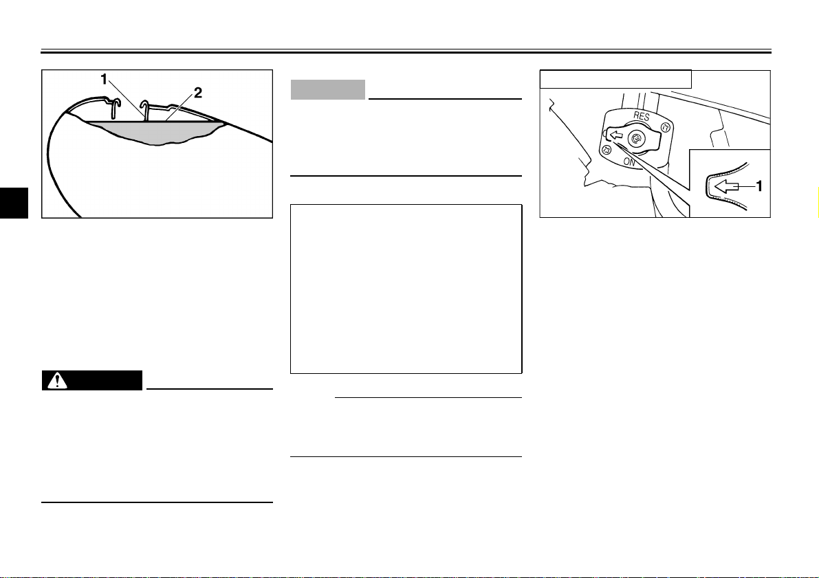
1. Filler tube
2. Fuel level
Fuel
Make sure there is sufficient fuel in the
tank. Fill the fuel tank to the bottom of
the filler tube as shown in the illustration.
WARNING
@
Do not overfill the fuel tank. Avoid
spilling fuel on the hot engine. Do
not fill the fuel tank above the bottom of the filler tube or it may overflow when the fuel heats up later and
expands.
@
EAU01183
EW000130
Recommended fuel:
Regular unleaded gasoline with a
research octane number of 91 or
higher.
Fuel tank capacity:
Total:
10.0 L
Reserve:
1.6 L
NOTE:
@
If knocking or pinging occurs, use a different brand of gasoline or higher octane grade.
@
EAU00185
EAU00191
1. Arrow mark positioned over “OFF”
EAU03050
Fuel cock
The fuel cock supplies fuel from the
tank to the carburetor while filtering it
also.
The fuel cock has three positions:
OFF
With the lever in this position, fuel will
not flow. Always return the lever to this
position when the engine is not running.
3-6
INSTRUMENT AND CONTROL FUNCTIONS
ON: normal position
1. Arrow mark positioned over “ON”
ON
With the lever in this position, fuel flows
to the carburetor. Normal riding is done
with the lever in this position.
RES: reserve position
1. Arrow mark positioned over “RES”
RES
This indicates reserve. If you run out of
fuel while riding, move the lever to this
position. Fill the tank at the first opportunity. Be sure to set the lever back to
“ON” after refueling!
3
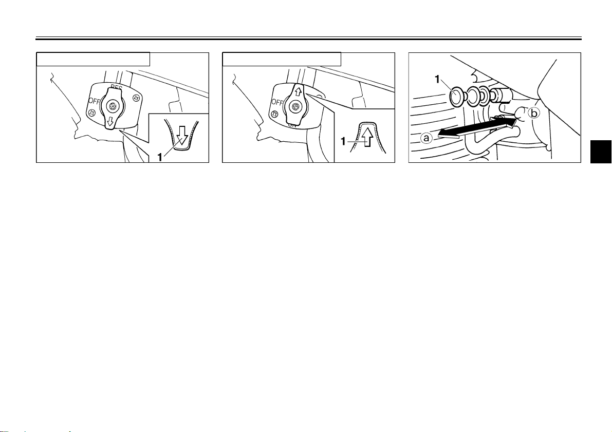
1. Starter (choke) knob
EAU03032
Starter (choke) knob
Starting a cold engine requires a richer
air-fuel mixture, which is supplied by
the starter (choke).
Move the knob in direction a to turn on
the starter (choke).
Move the knob in direction b to turn off
the starter (choke).
3-7
INSTRUMENT AND CONTROL FUNCTIONS
WARNING
3
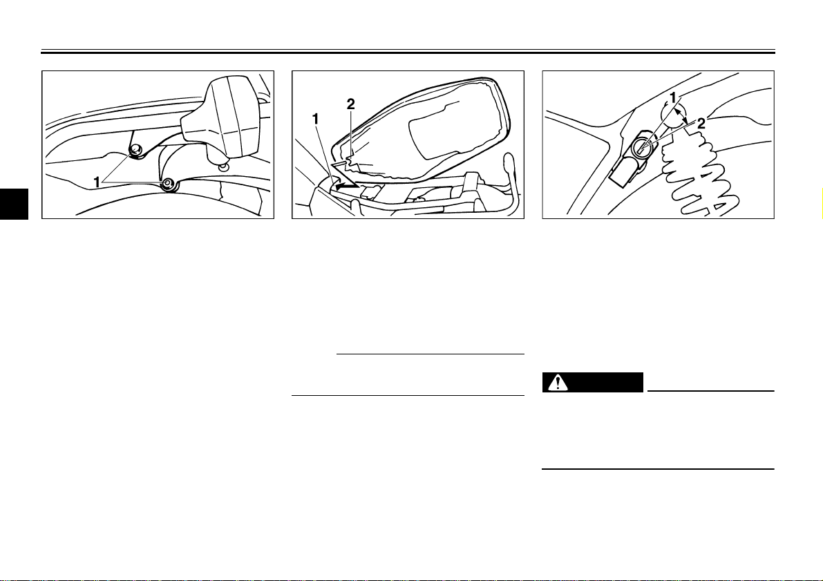
1. Bolt (× 2) 1. Seat holder
EAU01092
Seat
To remove the seat, remove the bolts.
2. Projection
To install the seat, insert the projection
on the front of the seat into the holder
and push down on the seat, then tighten the bolts.
NOTE:
@
Make sure that the seat is securely fitted.
@
1. Lock
2. Open
EAU00261
Helmet holder
To open the helmet holder, insert the
key in the lock and turn it as shown.
To lock the helmet holder, turn the key
to its original position.
EW000030
@
Never ride with a helmet in the helmet holder. The helmet may hit objects, causing loss of control and
possibly an accident.
@
3-8
INSTRUMENT AND CONTROL FUNCTIONS
WARNING
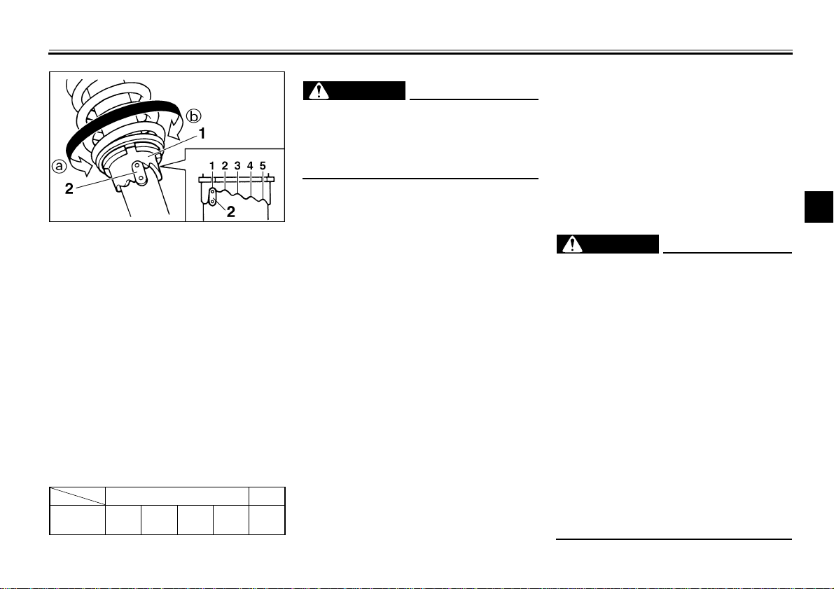
1. Spring preload adjusting ring
2. Position indicator
EAU00300
Rear shock absorber
adjustment
Each shock absorber is equipped with
a spring preload adjusting ring. Adjust
spring preload as follows. Turn the adjusting ring in direction a to increase
spring preload and in direction b to decrease spring preload. Make sure that
the appropriate notch in the adjusting
ring is aligned with the position indicator on the rear shock absorber.
CI-15E
Adjusting
position
Soft/Standard
12345
Hard
EW000040
WARNING
@
Always adjust each shock absorber
to the same setting. Uneven adjustment can cause poor handling and
loss of stability.
@
EAU00330
Sidestand
This model is equipped with an ignition
circuit cut-off system. The motorcycle
must not be ridden when the sidestand
is down. The sidestand is located on
the left side of the frame. (Refer to
page 5-1 for an explanation of this system.)
@
This motorcycle must not be operated with the sidestand in the down
position. If the stand is not properly
retracted, it could contact the
ground and distract the operator, resulting in a possible loss of control.
Yamaha has designed into this
motorcycle a lockout system to assist the operator in fulfilling the responsibility of retracting the
sidestand. Please check carefully
the operating instructions listed below and if there is any indication of a
malfunction, return the motorcycle
to a Yamaha dealer immediately for
repair.
@
EW000044
3
3-9
INSTRUMENT AND CONTROL FUNCTIONS
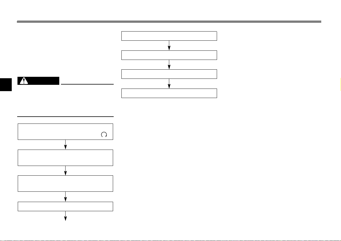
Sidestand/clutch switch
operation check
Check the operation of the sidestand
switch and clutch switch against the information below.
WARNING
@
3
Be sure to use the centerstand
●
during this inspection.
If improper operation is noted,
●
consult a Yamaha dealer.
@
CD-08E
TURN MAIN SWITCH TO “ON” AND
THE ENGINE STOP SWITCH TO “ ”.
TRANSMISSION IS IN GEAR AND
SIDESTAND IS UP.
PULL IN CLUTCH LEVER AND
PUSH START SWITCH.
EAU00332
EW000046
CD-08E
CLUTCH SWITCH IS OK.
SIDESTAND IS DOWN.
ENGINE WILL STALL.
SIDESTAND SWITCH IS OK.
ENGINE WILL START.
3-10
EAU01114
4-
PRE-OPERATION CHECKS
Owners are personally responsible for their vehicle’s condition. Your motorcycle’s vital functions can start to deteriorate
quickly and unexpectedly, even if it remains unused (for instance, if it is exposed t o the elements). Any damage, fluid leak or
loss of tire pressure could have serious consequences. Therefore, it is very important that, in addition to a thorough visual inspection, you check the following points before each ride.
EAU00340
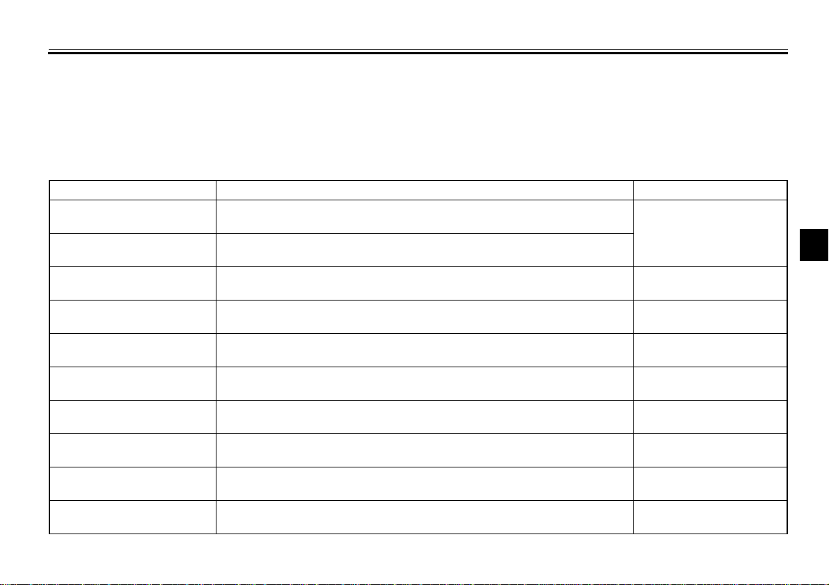
PRE-OPERATION CHECK LIST
ITEM CHECKS PAGE
Front brake
Rear brake
Clutch
Throttle grip and housing
Engine oil
Drive chain
Wheels and tires
Control and meter cables
Brake and shift pedal
shafts
Brake and clutch lever
pivots
• Check operation, free play, fluid level and fluid leakage.
• Fill with DOT 4 (or DOT 3) brake fluid if necessary.
• Check operation, condition and free play.
• Adjust if necessary.
• Check operation, condition and free play.
• Adjust if necessary.
• Check for smooth operation.
• Lubricate if necessary.
• Check oil level.
• Fill with oil if necessary.
• Check chain slack and condition.
• Adjust if necessary.
• Check tire pressure, wear, damage and spoke tightness.
• Tighten spokes if necessary.
• Check for smooth operation.
• Lubricate if necessary.
• Check for smooth operation.
• Lubricate if necessary.
• Check for smooth operation.
• Lubricate if necessary.
6-16 ~ 6-20
6-16
6-23
6-8 ~ 6-9
6-21 ~ 6-23
6-13 ~ 6-15, 6-30 ~ 6-33
6-23
6-24
6-24
4
4-1
PRE-OPERATION CHECKS
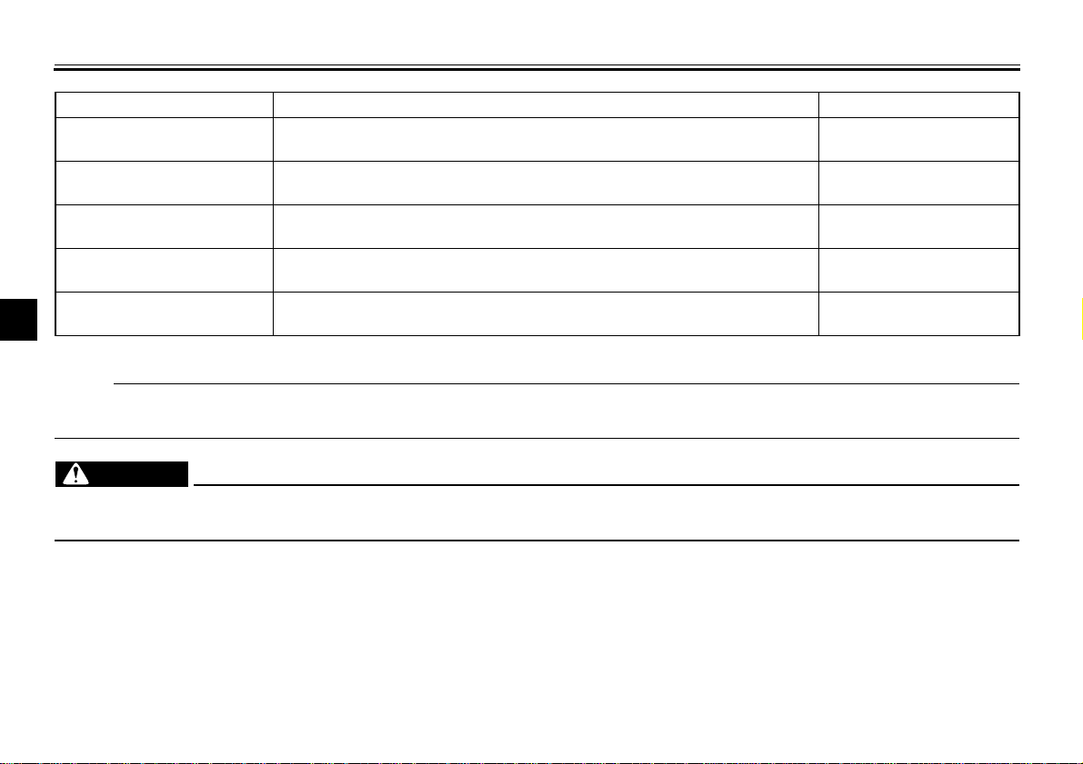
ITEM CHECKS PAGE
Center and sidestand
pivot
Chassis fasteners
Fuel
Lights, signals and
switches
Battery
4
NOTE:
Pre-operation checks should be made each time the motorcycle is used. Such an inspection can be thoroughly accomplished in a very short time; and the added safety it assures is more than worth the t ime in volved.
WARNING
If any item in the PRE-OPERATION CHECK is not working properly, have it inspected and repaired before operating
the motorcycle.
• Check for smooth operation.
• Lubricate if necessary.
• Make sure that all nuts, bolts and screws are properly tightened.
• Tighten if necessary.
• Check fuel level.
• Fill with fuel if necessary.
• Check for proper operation. 6-29 ~ 6-30
• Check fluid level.
• Fill with distilled water if necessary.
6-24
—
3-5 ~ 3-6
6-26 ~ 6-28
4-2
 Loading...