

Page 1
OWNER’S MANUAL
MANUEL DU PROPRIÉTAIRE
USO E MANUTENZIONE
INSTRUKTIONSBOK
OMISTAJAN KÄSIKIRJA
EIERHÅNDBOK
E
F
I
S
SF
N
E
F
I
S
SF
N
Read this manual carefully before operating this vehicle.
Il convient de lire attentivement ce manuel avant la première utilisation du véhicule.
Leggere attentamente questo manuale prima di utilizzare questo veicolo.
Läs den här instruktionsboken noga innan snöskotern används.
Lue tämä käsikirja huolellisesti ennen moottorikelkan käyttöä.
Les denne håndboken nøye før du tar kjøretøyet i bruk.
SR10ARLG
SR10ALLG
SR1ASD37G
SR1ASD46G
SR10AXLG
SR1AMS41G
SR10AM53G
SR1AMS53G
SR1AML53G
SR10AM62G
SR1AML62G
8KS-F8199-S1
Page 2

Original instructions
Notice originale
Istruzioni originali
Bruksanvisning i original
Alkuperäiset ohjeet
Opprinnelige instruksjoner
PRINTED IN U.S.A.
Page 3
Read this manual carefully
before operating this vehicle.
OWNER’S MANUAL
SR10ARLG
SR10ALLG
SR1ASD37G
SR1ASD46G
SR10AXLG
SR1AMS41G
SR10AM53G
SR1AMS53G
SR1AML53G
SR10AM62G
SR1AML62G
8KS-F8199-S1-E0
Page 4
Read this manual carefully before operating this vehicle. This manual
should stay with this vehicle if it is sold.
EC Declaration of Conformity
conforming to Directive 2006/42/EC
We, YAMAHA MOTOR CO., LTD. 2500 Shingai, Iwata, Japan,
declare in sole responsibility, that the product
SRV10RL(SR10ARL) (4UF8KN50 GT000001–)
SRV10LL(SR10ALL) (4UF8KP40 GT000001–)
SRV10MS53(SR1AMS53) (4UF8KS40 GT000001–)
SRV10ML62(SR1AML62) (4UF8KU40 GT000001–)
SRV10M53(SR10AM53) (4UF8KG40 GT000001–)
SRV10MS41(SR1AMS41) (4UF8LK20 GT000001–)
to which this declaration applies, conforms to the essential health and safety
requirements of Directive 2006/42/EC
SRV10SD37(SR1ASD37) (4UF8LJ20 GT000001–)
SRV10XL(SR10AXL) (4UF8LH20 GT000001–)
SRV10ML53(SR1AML53) (4UF8LL20 GT000001–)
SRV10M62(SR10AM62) (4UF8LM20 GT000001–)
SRV10SD46(SR1ASD46) (4UF8LN20 GT000001–)
(Make, model)
(
If applicable
)
and to the other relevant Directive of EEC
2004/108/EC
(
Title and/or number and date of issue of the other Directives of EEC
(
If applicable
)
To effect correct application of the essential health and safety requirements
stated in the Directives of EEC, the following-standards and/or technical
specifications were consulted:
)
– – – – – –
(
Title and/or number and date of issue of standards and/or specifications
)
Authorized Representative
YAMAHA MOTOR EUROPE N.V.
Koolhovenlaan 101, 1119 NC Schiphol-Rijk, The Netherlands
Signature
Akihiro Tsuzuki
General Manager
Engineering Div., RV Business Unit
Business Development Operations
Date of Issue
13 January, 2015
Page 5

Table of Contents
Foreword ...................................................... 2
General Information.................................3-14
Snowmobile Identification ............................3
Control Locations ......................................... 3
Gasoline-Oil .................................................4
Engine Break-In ...........................................4
Drive Belt Break-In ....................................... 5
Cold Drive-Away Function ............................5
Speedometer/Tachometer/Digital Gauge.....5
Diagnostic Codes.........................................7
Handlebar Tilt (Mountain Models) ................8
Handlebar Tilt (SR10 Models)...................... 8
Exhaust System ...........................................8
Air-Intake Silencer........................................8
Cooling System ............................................ 9
Battery.......................................................... 9
Jump-Starting...............................................9
Drive Clutch and Driven Clutch..................10
Drive Clutch/Driven Clutch Alignment ........11
Fuel Pump ..................................................11
Shock Absorbers (Rebuildable Gas) ..........11
Track/Track Studs ....................................... 11
Paddle Track (On Equipped Models)..........12
Reverse Operation ..................................... 12
Access Panel/Hood ....................................13
Removable Seat......................................... 13
Towing ........................................................ 14
Operating Instructions ...........................15-18
Starting and Stopping Engine .................... 15
Braking .......................................................16
Emergency Stopping..................................17
Throttle/Ignition Monitor Switch.................. 17
Varying Altitude Operation .........................18
Lubrication .............................................19-20
Chain Case ................................................ 19
Rear Suspension........................................ 20
Maintenance ..........................................21-42
Periodic Maintenance Checklist .................21
Fuel System ............................................... 22
Checking Engine Oil Level ......................... 22
Changing Engine Oil/Filter.........................22
Coolant Level ............................................. 24
Spark Plugs ................................................24
Checking/Adjusting Valve Clearance .........25
Battery........................................................25
Fuses .........................................................27
Brake System .............................................28
Burnishing Brake Pads............................... 30
Chain Tension ............................................ 31
Drive Belt.................................................... 31
Track Tension .............................................33
Track Alignment.......................................... 34
Suspension ................................................35
Adjusting Skid Frame Rear Shock (Limited
Models)...................................................37
Adjusting Rear Spring Pre-Load ................ 37
Lights..........................................................38
Ski Wear Bars ............................................ 39
Adjusting Ski Stance ..................................40
Single Wear Bar .........................................40
Dual Wear Bar............................................ 41
Rail Wear Strips ......................................... 41
Performance Tips ..................................43-44
Preparation for Storage ..............................45
Preparation after Storage ...........................46
Snowmobile Safety Rules...........................47
Page 6

Reference Information
Write the appropriate information for your Yamaha Snowmobile in the spaces below.
Always use these numbers when referring to your snowmobile.
Model: _________________________________________________
Date of Purchase: ________________________________________
Vehicle Identification Number: _______________________________
Engine Serial Number: _____________________________________
Your Yamaha Dealer: _____________________________________
Address: _______________________________________________
Phone: _________________________________________________
WARNING
A snowmobile is a very high performance vehicle. Because it does accelerate rapidly and is capable of very high speeds, it should not be operated by a
novice or an inexperienced operator. Never accelerate rapidly or drive at
high speed beyond the limits of visibility or without being totally familiar
with the terrain and what lies in front of you. Obey speed limits and never
operate at speeds that do not allow adequate maneuvering and stopping distances. Read and study the entire Operator’s Manual and Safety Handbook.
Failure to follow this warning could result in personal injury to yourself or
others.
Personal Injury
• To avoid injury to yourself and others, NEVER operate the snowmobile without first reading and understanding this manual and the Snowmobile Safety
Handbook; then follow the instructions and heed the warnings given.
• USE COMMON SENSE.
• DON’T DRINK and DRIVE.
• STAY IN CONTROL at ALL TIMES.
• TELL YOUR FRIENDS. If you see a friend operating a snowmobile recklessly, at excessive speeds, while intoxicated, or in other unsafe ways, don’t
wait until it is too late to warn of the consequences of snowmobile misuse.
Such conduct endangers everyone. TAKE AN ACTIVE ROLE IN THE
SAFETY OF YOURSELF AND OTHERS.
Parts and Accessories
When in need of replacement parts, oil, or accessories for your Yamaha Snowmobile, be sure to only use GENUINE YAMAHA PARTS, OIL, AND ACCESSORIES. Only genuine Yamaha parts, oil, and accessories are engineered to meet the
standards and requirements of your Yamaha Snowmobile. For a complete list of
accessories, refer to the current Yamaha Accessory Catalog. To aid in service and
maintenance procedures on these snowmobiles, an Illustrated Parts Manual and a
Service Manual are available through your local Yamaha Snowmobile dealer.
1
Page 7

Foreword
Congratulations! You have chosen a quality Yamaha Snowmobile designed and
assembled to give dependable service. Be sure, as the owner/operator of a Yamaha
Snowmobile, to become thoroughly familiar with its basic operation, maintenance,
and off-season storage procedures. Read this manual and the accompanying Snowmobile Safety Handbook before operating the snowmobile to learn safe and proper
use of your new Yamaha Snowmobile. Always operate the snowmobile within your
level of skill and current terrain conditions.
The Operator’s Manual, Snowmobile Safety Handbook, and Snowmobile Decals display the words Warning, Caution, and Note to emphasize important information. The
symbol WARNING identifies personal safety-related information. Be sure to follow the directive because it deals with the possibility of serious personal injury or
even death. A CAUTION identifies unsafe practices which may result in snowmobile-related damage. Follow the directive because it deals with the possibility of damaging part or parts of the snowmobile. The symbol
supplementary information worthy of particular attention.
This manual covers operator-related maintenance, operating instructions, and off season storage instructions. If major repair or service is ever required, contact an authorized Yamaha Snowmobile dealer for professional service.
At the time of publication, all information and illustrations were technically correct.
Some illustrations used in this manual are used for clarity purposes only and are not
designed to depict actual conditions. Because Yamaha constantly refines and
improves its products, no retroactive obligation is incurred.
This Operator’s Manual should be considered a permanent part of the snowmobile
and must remain with the snowmobile at the time of resale. If the snowmobile
changes ownership more than once, contact your yamaha.
Every Yamaha Snowmobile meets or exceeds the standards of the Snowmobile
Safety and Certification Committee and displays the SSCC decal. Yamaha endorses
and encourages the safe use of all snowmobiles. Always wear a helmet and eye protection. Drive with caution, observe all state and local regulations, and respect the
rights of others. ISMA members like Yamaha do their part to improve trails, sponsor
events, and generally support the sport of snowmobiling. As a member of the National Snowmobile Foundation, Yamaha promotes snowmobiling through education,
charity, and research programs.
© 2015 Yamaha
NOTE: identifies
2
Page 8
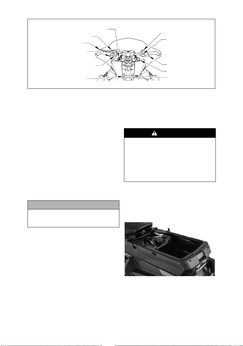
General Information
VIN
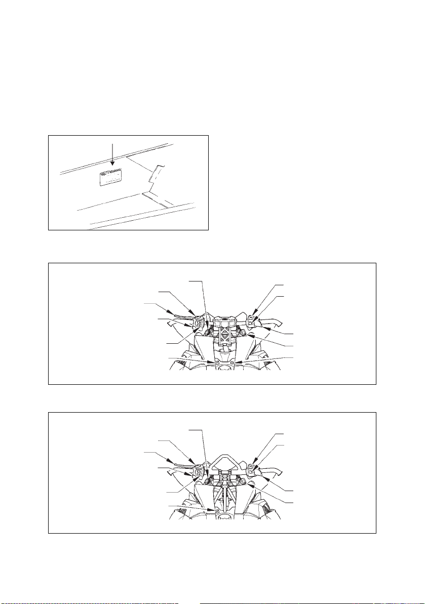
Accessory Outlet
Emergency Stop Switch
Reverse Switch
Throttle Lever
Ignition Switch
Heated Shield Outlet
(if equipped)
Brake Lever Lock
Brake Lever
Headlight Dimmer Switch
Thumb Warmer/
Handlebar Warmer Switches
Seat Warmer Switch (if equipped)
Tether Switch (if equipped)
Accessory Outlet
Emergency Stop Switch
Reverse Switch
Throttle Lever
Ignition Switch
Brake Lever Lock
Brake Lever
Headlight Dimmer Switch
Thumb Warmer/
Handlebar Warmer Switches
Seat Warmer Switch (if equipped)
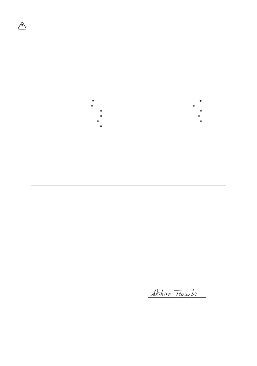
Snowmobile Identification
The snowmobile has two important identification numbers. The Vehicle Identification Number (VIN) is stamped into the
tunnel near the right-side footrest and on
a decal beneath the seat. The decal also
displays pertinent production information. The Engine Serial Number (ESN) is
stamped into the crankcase of the engine.
0726-383
SR10 Models
These numbers are required by the dealer
to complete warranty claims properly. No
warranty will be allowed by Yamaha Inc.
if the engine serial number or VIN is
removed or mutilated in any way.
Always provide the snowmobile name,
VIN, and ESN when contacting an authorized Yamaha Snowmobile dealer for
parts, service, accessories, or warranty. If
the complete engine must be replaced,
ask the dealer to notify Yamaha for correct registration information.
Control Locations
Shown are the typical control locations
for Yamaha snowmobiles. Location of a
specific control will vary according to
model.
3
SR10 Long Track Models
0749-256
0749-257
Page 9
Gasoline-Oil
Accessory Outlet
Emergency Stop Switch
Reverse Switch
Throttle Lever
Ignition Switch
Heated Shield Outlet
Brake Lever Lock
Brake Lever
Headlight Dimmer Switch
Thumb Warmer/
Handlebar Warmer Switches
Seat Warmer Switch
Recommended Gasoline
The recommended gasoline to use in
these snowmobiles is RON 95 octane
regular unleaded. In many areas, oxygenates are added to the gasoline. Oxygenated gasolines containing up to 10%
ethanol are acceptable gasolines.
When using ethanol blended gasoline, it is
not necessary to add a gasoline antifreeze
since ethanol will prevent the accumulation of moisture in the fuel system.
Recommended Engine Oil
The recommended oil to use is SemiSynthetic Yamalube 0W-30 oil.
CAUTION
Any oil used in place of the recommended oil could cause serious
engine damage
After 800 km (500 miles) of operating,
the engine oil must changed and the oil
filter replaced. The engine oil should be
changed every 4000 km (2500 miles)
before prolonged storage and the oil filter
should be changed every 20,000 km
(12,500 miles).
Filling Gas Tank
Since gasoline expands as its temperature
increases, the gas tank must be filled to
its rated capacity only. Expansion room
must be maintained in the tank particularly if the tank is filled with cold gasoline and then moved to a warm area.
SR10SD46 Models
Also, if the snowmobile is to remain on a
trailer after filling the gas tank, the bed of
the trailer must be maintained level to
prevent gasoline from draining out
through the gas tank vent hose.
Always fill the gas tank in a well-ventilated area. Never add gasoline to
the snowmobile gas tank near any
open flames or with the engine running. DO NOT SMOKE while filling
the gas tank. Do not sit on the snowmobile without first installing the gas
tank cap.
The SR10SD46 features a 15.9 L (4.2 US
gallon) auxiliary gas tank. A separate gas
tank cap is located beneath the cowling
just behind the operator seat. The auxiliary tank is plumbed directly into the
main gas tank.
Engine Break-In
The engine (when new or rebuilt)
requires a short break-in period before
the engine is subjected to heavy load conditions.
0749-258
WARNING
YM-126
4
Page 10
This engine does not require any pre-
Upper Left
Button
Lower Left
Button
Upper Right
Button
Lower Right
Button
A B C D
G
H
G
F
E
mixed fuel during the break-in period.
There is never a more important period in
the life of the engine than the first 500
km (300 miles).
Since the engine is brand new, do not put
an excessive load on it for the first 500
km (300 miles). The various parts in the
engine wear and polish themselves to the
correct operating clearances. During this
period, prolonged full throttle operation
or any condition that might result in
engine overheating must be avoided.
Operating your snowmobile for the first
time: Start the engine and let it idle for 15
minutes.
0-160 km (0–100 miles): Avoid prolonged operation above 6000 RPM.
160-500 km (100–300 miles): Avoid prolonged operation above 8000 RPM.
500 km (300 miles) and beyond: The
snowmobile can now be operated normally.
NOTE: After 800 km (500 miles) of
operation, the engine oil must be
changed and the oil filter replaced.
If any engine trouble should occur
during the engine break-in period,
immediately have a Yamaha dealer
check the snowmobile.
Drive Belt Break-In
Drive belts require a break-in period of 40
km (25 miles). Drive the snowmobile for
40 km (25 miles) at 3/4 throttle or less. By
revving the engine up and down (but not
exceeding 100 km/h [60 mph]), the
exposed cord on the side of a new belt will
be worn down. This will allow the drive
belt to gain its optimum flexibility and
will extend drive belt life.
NOTE: Before starting the snowmobile in extremely cold temperatures, the drive belt should be
removed and warmed up to room
temperature. Once the drive belt is
at room temperature, install the
drive belt.
CAUTION
Never run the engine with the drive
belt removed. Excessive revving of
the engine could result in serious
engine damage and drive clutch
failure.
Cold Drive-Away Function
There is a “cold drive-away” function
incorporated within the engine.
NOTE: When cold-starting the
engine, the coolant temperature
warning icon will illuminate and the
LOW TEMP display on the readout
screen will begin to flash. With the
engine in this temperature range,
the RPM “limit” of the engine will
be below drive system engagement
speed. As the engine warms, the
coolant temperature warning icon
will begin to flash, the TEMP display will continue to flash, and the
RPM “limit” of the engine will
increase allowing the snowmobile
to move without full-throttle operation. When the engine reaches
proper operating temperature, the
coolant temperature warning icon
and the LOW TEMP display will go
out.
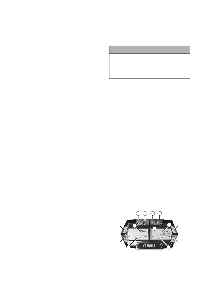
Speedometer/Tachometer/ Digital Gauge
5
CWI-050A
Page 11

A. Coolant Temperature Indicator
The indicator and LOW TEMP display
will cease to flash when the engine
reaches proper operating temperature.
If the coolant temperature rises too far
above proper operating temperature, the
indicator will flash a warning (alert) and
the engine will “surge” to alert the operator. If the coolant temperature rises to a
critical point above proper operating temperature, the indicator will cease flashing
and will remain constantly illuminated.
NOTE: If the indicator is con-
stantly on, the engine will shut off
if vehicle speed is reduced to 1.5
km-h (0.9 MPH) or slower.
CAUTION
If the indicator is illuminated, stop the
engine immediately and allow it to
cool down. If unable to either determine or remedy the problem, take the
snowmobile to an authorized Yamaha
Snowmobile dealer for service. If not
under warranty, this service is at the
discretion and expense of the snowmobile owner.
B. High Beam Indicator
The indicator is on whenever the high
beam mode is selected by the headlight
switch.
C. Oil Pressure Indicator
The indicator relates to engine oil pressure, not the oil level; however, if the oil
level is low, it may affect oil pressure. If
oil pressure is lost, check the oil level
(see page 22).
If the indicator does not go out or if the
engine does not start, take the snowmobile to an authorized Yamaha Snowmobile dealer. If not under warranty, this
service is at the discretion and expense of
the snowmobile owner.
D. Low Fuel Indicator
The indicator illuminates whenever the
gas in the gas tank is low.
E. Coolant Temperature/Battery
Voltage/Intake Air Temperature
This bar display shows coolant temperature, battery voltage, and intake air temperature. Press the Lower Left Button to
change which parameter is being displayed. Press and hold the Lower Left
Button to see the actual values associated
with the mode selected.
F. Fuel Level Display
This display shows the approximate
amount of gas remaining in the gas tank.
G. RPM/Speed/Clock/Altimeter
Press the Upper Left Button to cycle the
left screen between RPM and speed.
NOTE: When RPM is displayed on
the left screen, the right screen will
display speed, clock, or altimeter.
When speed is displayed on the
left screen, the right screen will
display RPM, clock, or altimeter.
Press the Upper Right Button to cycle the
right screen between speed, RPM, clock,
and altimeter.
Press and hold the Upper Button on the
speed-side of the gauge to shift the gauge
between standard (MPH/miles/fahrenheit) and metric (km/h/kilometers/celsius) modes.
Press and hold the Upper Button on the
RPM-side of the gauge to view maximum RPM. This value is reset each time
the ignition key is turned off.
With the clock mode selected by pressing
the Upper Right Button, press and hold
the Upper Right Button to set the clock.
The option of selecting the 12-hour or
24-hour clock is available; press the
either Left Button to alternate between
the two modes. Next, press the Lower
Right Button to set the clock. Press either
Left Button to set the hours; then press
the Lower Right Button to set the minutes. Press either Left Button to set the
minutes. When the proper time has been
set, press the Lower Right Button to
return to the main gauge display.
6
Page 12

With the altimeter mode selected by
pressing the Upper Right Button, press
and hold the Upper Right Button to set
the current altitude by using either Left
Button. When the proper altitude has
been set, press the Lower Right Button to
return to the main gauge display.
H. Engine Hour Meter/Odometer/
Trip Meter/Clock
This display shows engine hours, odometer, trip meter, or clock. Press the Lower
Right Button to change which parameter
is being displayed. The Engine Hour
Meter and Odometer cannot be reset. To
reset the trip meter, select the Trip Meter;
then press and hold the Lower Right Button until the trip meter display reads 0.
NOTE: The clock can only be dis-
played in this position if it is not
already being displayed in the main
right screen. To set the clock when
the clock is in this position, press
and hold the Lower Right Button;
then use the procedure found in G.
Diagnostic Codes
Diagnostic codes are activated by the
ECM and may be displayed on the readout screen for a number of reasons.
If a code is displayed while the engine is
running, the ECM is receiving input that
is outside of its established parameters. If
a code has been activated, take the snowmobile to an authorized Yamaha Snowmobile dealer for service. If not under
warranty, this service is at the discretion
and expense of the snowmobile owner.
Refer to the following chart for diagnostic codes.
Code Trouble
P0031 O2 Heater Control Circuit Low
P0032 O2 Heater Control Circuit High
P0107 Manifold absolute pressure circuit low
P0108 Manifold absolute pressure circuit
high
P0112 Intake air temp sensor circuit low
P0113 Intake air temp sensor circuit high
P0115 Engine coolant temp sensor 1 circuit
P0117 Engine coolant temp sensor 1 circuit
low
P0118 Engine coolant temp sensor 1 circuit
high
P0120 Throttle position sensor circuit
Code Trouble
P0122 Throttle position sensor circuit low
P0123 Throttle position sensor circuit high
P0130 O2 sensor circuit
P0131 O2 sensor circuit low
P0132 O2 sensor circuit high
P0171 System too lean
P0172 System too rich
P0201 Injector circuit/open - cylinder 1
P0202 Injector circuit/open - cylinder 2
P0203 Injector circuit/open - cylinder 3
P0217 Engine coolant over temp condition
P0261 Cylinder 1 injector circuit low
P0264 Cylinder 2 injector circuit low
P0267 Cylinder 3 injector circuit low
P0508 Idle air control system circuit low
P0509 Idle air control system circuit high
P0511 Idle air control circuit
P0522 Engine oil pressure sensor circuit low
P0523 Engine oil pressure sensor circuit high
P0562 System voltage low
P0563 System voltage high
P0780 Shift Error
P1315 Crankshaft Position out of sync
P1338 Crankshaft spike detected
P1339 Crankshaft tooth not detected
P1685 Main relay open circuit
P1686 Main relay circuit low
P1688 Reverse relay open circuit
P1689 Reverse relay circuit low
P1691 Forward relay open circuit
P1692 Forward relay circuit low
P1694 Headlight relay open circuit
P1695 Headlight relay circuit low
P2228 Barometric pressure sensor A circuit
low
P2229 Barometric pressure sensor A circuit
high
P2300 Ignition coil A primary control circuit
low
P2303 Ignition coil B primary control circuit
low
P2306 Ignition coil C primary control circuit
low
U0155 Lost communication with the ECM
7
Page 13
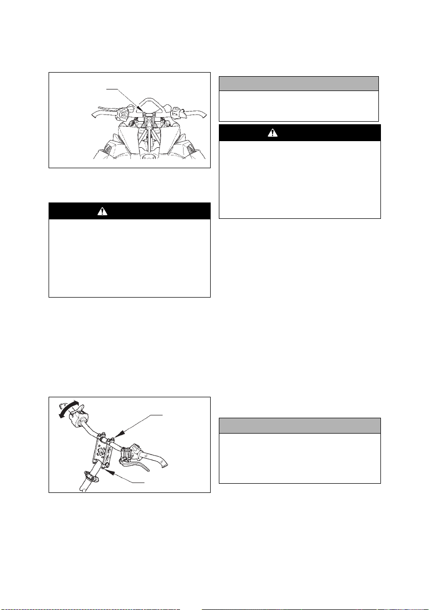
Handlebar Tilt
Cap Screws
Cap Screws
(Mountain Models)
1. Loosen the four cap screws and tilt
the handlebar to the desired position.
2. Adjust the handlebar to operator’s
desired position, tighten the cap
screws evenly to 2.0 kg-m (15 ft-lb),
and check steering for maximum
right/left turning capabilities.
Machine Screws
0748-905
2. Tighten the four cap screws evenly
to 15 ft-lb.
WARNING
Tighten the cap screws according
to specifications to prevent unexpected “movement” of the handlebar during operation over rough
terrain. DO NOT position handlebar
so steering (maximum right/left
turning capabilities) or throttle and
brake controls are affected.
Handlebar Tilt (SR10 Models)
The handlebar can be adjusted to the
operator’s preference. To adjust the handlebar, use the following procedure:
1. Remove the handlebar cover; then
loosen the eight cap screws securing
the handlebar caps to the riser and the
riser to the steering post.
CAUTION
Do not rotate the handlebar to a
position that allows air to enter the
brake system.
WARNING
Tighten cap screws according to
specifications to prevent unexpected “movement” of the handlebar during operation over rough
terrain. DO NOT position the handlebar so steering (maximum right/
left turning capabilities) or throttle
and brake controls are affected.
Exhaust System
The exhaust system is designed to reduce
noise and to improve the total performance of the engine. If any exhaust system component is removed from the
engine and the engine is run, severe
engine damage will result.
Air-Intake Silencer
Used in conjunction with the fuel intake
system is a specially designed air-intake
silencer. The purpose of the silencer is to
quiet the intake of fresh air. Since the fuel
intake system is calibrated with the airintake silencer in place, the engine must
never be run with the silencer removed.
Performance will not be improved if the
air-intake silencer is removed. In contrast, severe engine damage will occur.
CAUTION
These snowmobiles are not
designed to be operated in dusty
conditions. Operating the snowmobile in dusty conditions will result
in severe engine damage.
0747-828
8
Page 14
Cooling System
These snowmobiles are equipped with a
closed liquid cooling system for engine
cooling. The cooling system should be
inspected daily for leakage and damage.
Also, the coolant level should be checked
daily. If leakage or damage is detected,
take the snowmobile to an authorized
Yamaha Snowmobile dealer for service.
If not under warranty, this service is at
the discretion and expense of the snowmobile owner.
When filling the cooling system, use an
ethylene glycol-based coolant/water mixture which will satisfy the coldest anticipated weather conditions of your area in
accordance with the coolant manufacturer’s recommendations.
NOTE: If operating on ice or hard-
packed snow conditions, it is recommended that Ice Scratchers be
installed to reduce wear strip wear
and engine overheating.
For checking/filling cooling system, refer
to Coolant Level sub-section in the Maintenance section.
Battery
It is extremely important that the battery
be maintained at full charge at all times
and that the battery connections be clean
and tight. If charging the battery becomes
necessary, refer to Battery sub-section in
the Maintenance section.
CAUTION
Always turn the ignition switch key
to the OFF position when the snowmobile is not being used. Leaving
the ignition switch in the ON position will result in discharging the
battery and possible damage to the
battery.
Jump-Starting
NOTE: Yamaha does not recom-
mend jump-starting a snowmobile
with a dead battery but rather to
remove the battery, service it, and
correctly charge it; however, in an
emergency, it may be necessary to
jump-start a snowmobile. If so, use
the following procedure to carefully and safely complete this procedure.
WARNING
Improper handling or connecting of
a battery may result in severe injury
including acid burns, electrical
burns, or blindness as a result of an
explosion. Always remove rings
and watches. Any time service is
performed on a battery, the following must be observed: keep sparks,
open flame, cigarettes, or any other
flame away. Always wear safety
glasses. Protect skin and clothing
when handling a battery. When servicing a battery in an enclosed
space, keep the area well-ventilated.
NOTE: To access the battery, the
seat must be removed.
1. For the snowmobile to be jumpstarted, slide any terminal boots away.
2. Inspect the battery for any signs of
electrolyte leaks, loose terminals, or
bulging sides. Leaking or bulging
battery cases may indicate a frozen
or shorted battery.
WARNING
If any of these conditions exist, DO
NOT attempt to jump-start, boost, or
charge the battery. An explosion
could occur causing serious injury.
9
Page 15
3. Inspect the snowmobile to be used for
jump-starting to determine if voltage
and ground polarity are compatible.
The vehicle must have a 12-volt DC,
negative ground electrical system.
CAUTION
Always make sure the electrical
systems are of the same voltage
and ground polarity prior to connecting jumper cables. If not,
severe electrical damage may
occur.
4. Move the vehicle to be used for the
jump-start close enough to ensure
the jumper cables easily reach; then
set and lock the brakes, shut off all
electrical accessories, and turn the
ignition switch OFF.
NOTE: Make sure all switches on
the snowmobile to be jump-started
are turned OFF.
5. Disconnect all external accessories
such as cell phones, GPS units, and
radios on both vehicles.
CAUTION
Failure to disconnect electronic
accessories during jump-starting
may cause system damage due to
power spikes.
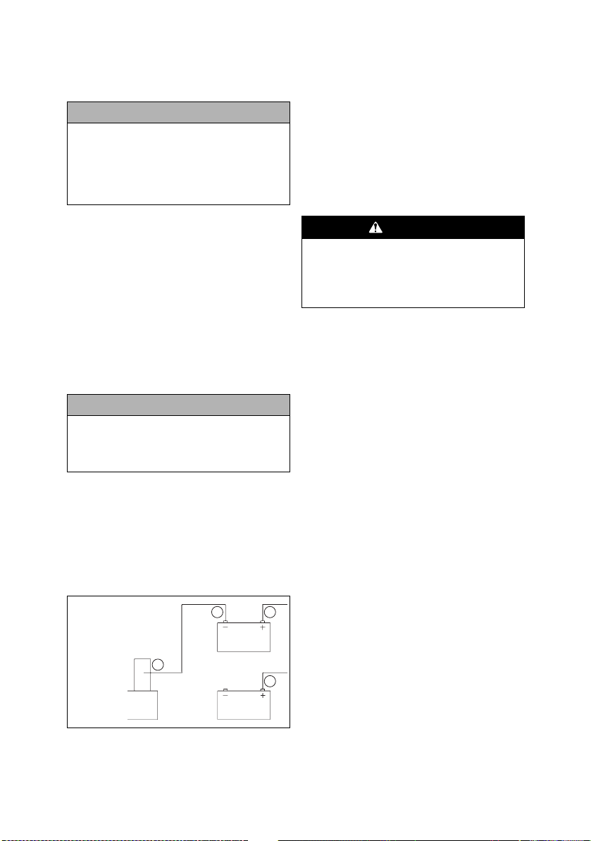
6. Attach one clamp of the positive
(red) cable to the positive (+) terminal (1) of the dead battery (C) being
careful not to touch any metal with
the other clamp; then attach the
other clamp of the positive (red)
cable to the positive (+) terminal (2)
of the good battery (B).
A. Unpainted Surface on Engine
B. Good Battery
C. Dead Battery
4
A
23
B
1
C
0744-527
NOTE: Some jumper cables may
be the same color but the clamps or
ends will be color-coded red and
black.
7. Attach one clamp of the negative
jumper cable (black) to the negative
(-) terminal (3) of the good battery
(B); then attach the other clamp of
the negative (black) jumper cable (4)
to an unpainted metal surface (A) on
the engine or frame well away from
the dead battery and fuel system
components.
WARNING
Never make the final connection to a
battery as a spark could ignite hydrogen gases causing an explosion of the
battery resulting in acid burns or
blindness.
8. Stand well away from the dead battery and start the vehicle with the
good battery. Allow the vehicle to
run for several minutes applying
some charge to the dead battery.
9. Start the snowmobile with the dead
battery and allow it to run for several
minutes before disconnecting the
jumper cables.
10. Remove the jumper cables in opposite order of hook-up (4, 3, 2, 1). Be
careful not to short cables against
bare metal.
NOTE: Have the battery and elec-
trical system checked prior to
operating the snowmobile again.
Drive Clutch and Driven Clutch
The drive clutch and driven clutch do not
require lubrication; therefore, no special
maintenance is required by the snowmobile owner except for periodical cleaning.
However, the drive clutch and driven
clutch should be disassembled, cleaned,
and inspected by an authorized Yamaha
Snowmobile dealer after every 4000 km
(2500 miles) or seasonally, whichever
occurs first. This service is at the discretion
and expense of the snowmobile owner.
10
Page 16

When operating the snowmobile at high
altitudes, it may be necessary to change
certain component parts of the drive
clutch and/or the driven clutch. See an
authorized Yamaha Snowmobile dealer
for further information.
CAUTION
DO NOT attempt to service the drive
clutch and driven clutch. The drive
clutch and driven clutch must be serviced by an authorized Yamaha
Snowmobile dealer only.
Drive Clutch/Driven Clutch Alignment
The alignment between the drive clutch
and driven clutch is set at the factory.
Normally, no adjustment is necessary as
long as neither the drive clutch nor the
driven clutch is removed or disassembled. However, if premature drive belt
wear is experienced or if the drive belt
turns over, the drive clutch/driven clutch
alignment must be checked. Take the
snowmobile to an authorized Yamaha
Snowmobile dealer for this service. If not
under warranty, this service is at the discretion and expense of the snowmobile
owner.
Fuel Pump
The fuel pump is designed to provide
adequate amount of gas to the
at all throttle settings. If a fuel delivery
problem is suspected, take the snowmobile to an authorized Yamaha Snowmobile dealer. If not under warranty, this
service is at the discretion and expense of
the snowmobile owner.
injectors
Shock Absorbers (Rebuildable Gas)
Each shock absorber should be visibly
checked weekly for fluid leakage, cracks or
breaks in the body/reservoir, or a bent shaft.
If any one of these conditions is detected,
replacement or service is necessary. Take the
snowmobile to an authorized Yamaha
Snowmobile dealer for this service. If not
under warranty, this service is at the discretion and expense of the snowmobile owner.
NOTE: When the snowmobile is
operated in extremely cold
weather (-23°C/-10°F or colder), a
small amount of leakage may be
present. Unless the leakage is
excessive, replacement is not necessary.
NOTE: The frequency of servic-
ing rebuildable shock absorbers
will vary according to the types of
conditions and terrain the snowmobile has been subjected to. If
riding quality deteriorates (or
seems to be deteriorating), take the
snowmobile to an authorized
Yamaha Snowmobile dealer for
shock absorber evaluation and/or
servicing. This service is at the discretion and expense of the snowmobile owner.
Track/Track Studs
Accelerated wear strip and track clip
wear caused by operating on ice or hardpacked snow conditions is NOT covered
under Yamaha warranty policy.
NOTE: If regularly operating on
ice or hard-packed snow conditions, Performance Wear Strips
may be installed at the expense of
the snowmobile owner.
In general, track life will be shortened
when studs are installed. Drilling stud
holes into the drive track will cut the
internal fibers weakening the track.
Avoid spinning the drive track. Studs
may catch on an object and pull out of the
track leaving tears and damage around
the already weakened area. To minimize
possible damage, consult your stud manufacturer for installation and stud pattern
recommendations. Yamaha does not recommend studding a track.
11
Page 17
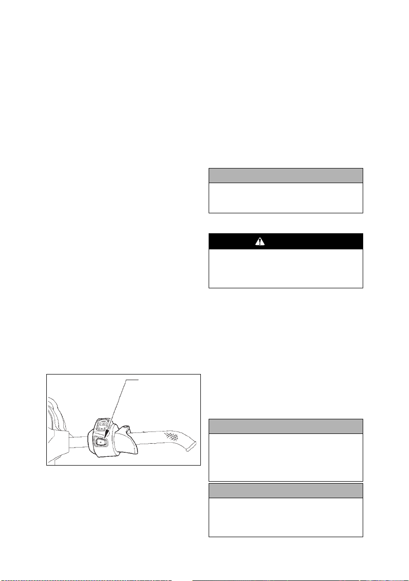
Paddle Track (On Equipped
Reverse Switch Button
Models)
These models are equipped with a Power
Claw style track which is specially
designed for use in powder snow riding
conditions. When the Power Claw track
is operated in hard-packed snow conditions, it will run slightly slower than a
standard track and it will accelerate wear
strip wear. To decrease the amount of
wear strip wear, slower speeds must be
maintained when operating on hardpacked trails. Accelerated wear strip
wear caused by operating a Power Claw
track on hard-packed snow conditions is
NOT covered under Yamaha warranty
policy.
NOTE: If operating on ice or hard-
packed snow conditions, it is recommended that Ice Scratchers be
installed to reduce wear strip wear
and engine overheating.
Reverse Operation
The electrical reverse function offers the
operator the convenience of being able to
back up the snowmobile rather than having
to turn the snowmobile around by hand.
This feature, under most situations, should
not be used to free a stuck snowmobile as
it will tend to dig the skis deeper into the
snow. Always use minimal speed when
operating in reverse and come to a complete stop before shifting from either forward to reverse or reverse to forward.
Shifting Into Reverse
1. Always warm up the engine for 2-3
minutes prior to shifting into reverse.
2. With the engine at idle (under 2500
RPM) and the snowmobile at a complete stop, press and release the
reverse switch button.
NOTE: The snowmobile must be
at a complete stop and the engine
running under 2500 RPM before the
system will allow shifting.
3. When reverse is engaged, a reverse
icon will illuminate on the deluxe
digital gauge and a reverse alarm
will sound.
CAUTION
Never shift into reverse while the
snowmobile is moving forward as it
is hard on the drive system.
Operating in Reverse
WARNING
Use caution and minimal speed
when operating the snowmobile in
reverse. Be sure the button is in the
desired position.
1. When shifting into reverse, always
wait for the reverse icon to illuminate and the reverse alarm to sound
before backing up.
NOTE: The reverse function is cancelled whenever the engine is shut
off.
2. After shifting from reverse to forward (or from forward to reverse),
apply the throttle slowly and evenly
to allow the driven pulley to engage
properly.
741-438A
NOTE: Correct drive belt tension
(deflection) is important for the
reverse function to operate properly. If the belt is too tight, difficulty
in engaging reverse will be experienced.
CAUTION
After reversing in deep powder
snow conditions, make sure the
snowflap does not become “caught
up” in the track. Track and/or snowflap damage may occur.
CAUTION
If the snowmobile is equipped with
ice scratchers, the scratchers must
be disengaged or component damage will occur.
12
Page 18

Access Panel/Hood
Torx Head Screw
To remove the access panel and hood, use
the following procedure:
1. Remove the hairpin clip from the pin
located at the front of the access
panel. Remove the thumb screw
securing the front left access panel
to the front fascia. Move the panel
up and off the pin; then swing the
panel all the way out and unhinge
the panel from the lower console.
2. Remove the torx-head screws securing the hood (located on the underside
of the hood above the front tube of the
upper A-arm); then remove the torxhead screws from the top-side of the
hood securing the hood to the upper
console and the torx-head screws
from under the nosepiece of the hood.
Torx Head Screw
Removable Seat
To remove the seat, remove the torx-head
screw from the underside of the seat; then
lift on the back of the seat and move it up
and rearward to remove it.
CAUTION
Prior to removing the seat, lift the
rear of the seat and disconnect the
seat heater harness connector.
0747-739
To install the seat, route the front tab on
the seat through the seat-base hold-down
bracket; then install the seat and secure
using the torx-head screw.
Torx Head Screws
Torx Head Screw
0747-830
3. Remove the intake panel below the
gauge; then locate the hood harness
connector (located in front of the
speedometer) and unplug the connector; then move the hood slightly
forward and remove the hood.
To install the access panel and hood, use
the following procedure:
1. Position the hood onto the snowmobile and connect the hood harness
connector making sure the harness
does not become pinched.
2. Secure the hood with torx-head
screws and tighten securely.
3. Install the access panel onto the
lower console; then close the access
panel and secure with the hairpin
clip. Install the intake panel.
13
SNO-273
NOTE: Prior to lowering and
securing the seat, connect the seat
heater harness connector.
NOTE: On SR10SD46 models,
pull back on the seat retainer pin
and remove the seat. Make sure to
disconnect the seat heater harness.
Page 19

0748-419
Towing
If the snowmobile is to be towed by
another snowmobile, do not tow using
the loops in the skis. The tow rope should
be attached to the spindles.
14
Page 20

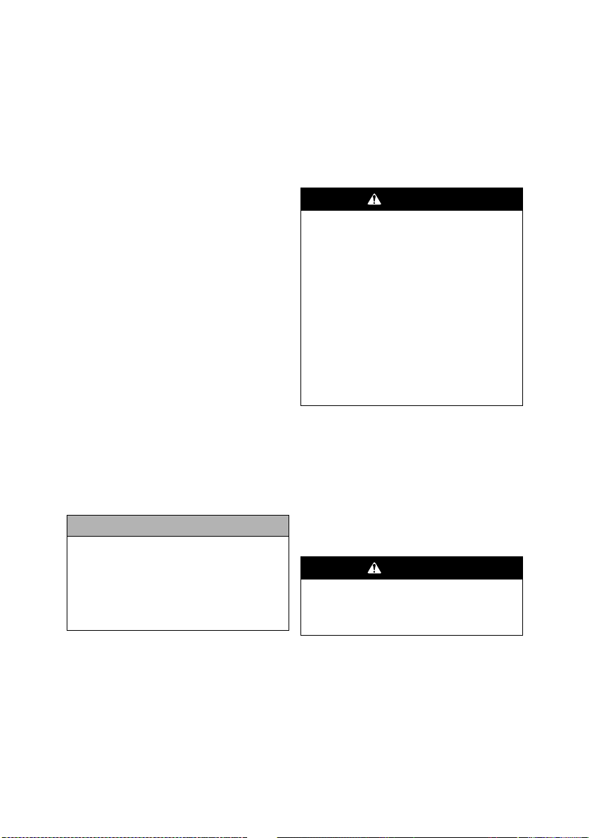
Starting and Stopping Engine
High Brake Fluid Mark
Low Brake Fluid Mark
It is imperative that the brake system be
checked for wear and proper operation.
After the engine has been started, check
the headlights (high and low beam), taillight, and brakelight to be sure they are
working properly and adjusted correctly.
Make sure all lights are clean to provide
maximum illumination. The headlight
and taillight must be clean and must be
illuminated whenever the engine is running.
Engine startup at ambient temperature below minus 30 °C is not guaranteed.
Manual emergency startup of engine
is not provided.
1. Test the operation of the brake sys-
2. With the brake fluid reservoir in a
Operating Instructions
WARNING
WARNING
tem by compressing the brake lever.
The brake lever must feel firm when
compressed; then while holding the
brake lever in the compressed position, measure the distance between
the brake lever and the handlebar.
The distance must be greater than
2.54 cm (1 in.).
1 in.
0745-816
level position and the cover
removed, check the fluid level. The
brake fluid level must be at the high
brake fluid mark in the reservoir.
0745-817
3. If the brake fluid is below the high
brake fluid mark, add Yamaha
approved DOT 4 brake fluid until
the fluid is at the recommended
level. Install and secure the reservoir
cover. Do not allow moisture to contaminate the brake system.
CAUTION
Brake fluid is highly corrosive. Do
not spill brake fluid on any surface
of the snowmobile.
WARNING
Do not overfill the brake fluid reservoir. Overfilling the reservoir may
cause the brake system to hydraulically lock. Use only Yamaha
approved brake fluid.
WARNING
Do not start the engine if the brake
system is not functioning properly.
Service the brake system or have it
properly repaired prior to operating
the snowmobile. Serious personal
injury or even death may occur if the
brake system is not operating properly.
4. Test the throttle control lever by
completely compressing and releasing it several times. The lever
MUST return to the idle position
quickly and completely.
CAUTION
Always check the coolant level
before starting the engine.
5. Move the emergency stop switch to
the UP or RUN position.
15
Page 21

6. Insert key into ignition switch; then
rotate key to the RUN position.
NOTE: Rotate the key to the START
position; then when the engine starts,
release the key.
CAUTION
Do not continuously run the starter
for more than 5 seconds at a time.
NOTE: When the engine starts,
allow it to warm up properly. Idle the
engine several minutes until the
engine has reached normal operating temperature. Do not idle the
engine for excessively long periods
of time.
7. There is a “cold drive-away” function
incorporated within the engine. This
function is active until the engine
reaches operating temperature.
8. Flooding — If the engine does not
start but seems ready to start, engage
the brake lever lock; then compress
the throttle control lever fully and try
to start the engine. When the engine
starts, release the throttle control lever
immediately. After the warm-up,
release the brake lever lock.
9. To shut off the engine, turn the ignition key to the OFF position or push
the emergency stop switch to the
DOWN position.
CAUTION
Always turn the ignition switch key to
the OFF position when the snowmobile is not being used. Leaving the
ignition switch in the ON position will
result in discharging the battery and
possible damage to the battery.
Braking
The following items are items that the
operator must be familiar with when
operating this snowmobile and its
hydraulic brake system. Important additional information on the proper maintenance of the brake system is found in the
Maintenance section.
1. Use the brakes wisely. Each time the
brakes are applied in all hydraulic
brake systems (including automotive
applications), heat is transferred to the
brake fluid. The amount of heat transferred during high speed stops and/or
repetitive use may be high enough to
boil the brake fluid and cause the
brakes to either fade or may cause an
unexpected loss of brakes. If this
occurs, the brake fluid requires a cooldown period before the brakes will
again function properly.
This cool-down period will vary
depending upon the ambient air temperature and the temperature of the
brake fluid. If loss of brakes has
occurred because of high fluid temperatures, do not operate the snowmobile
until the cool-down period has expired
and brake lever firmness has returned.
WARNING
Excessive, repetitive use of the
hydraulic brake for high speed
stops will cause overheating of the
brake fluid and premature brake
pad wear which will result in an
unexpected loss of brakes.
2. Be sure to maintain the brake fluid at
the proper level and take care not to
get any moisture in the system as
moisture in the brake fluid lowers the
boiling point. If the brake fluid is ever
boiled (by high speed stops or repetitive use) or if moisture is allowed to
enter the system, it must be changed.
Never substitute or mix different types
or grades of brake fluid.
WARNING
Use only Yamaha approved DOT 4
brake fluid. Never substitute or mix
different types or grades of brake
fluid. Brake loss can result. Check
brake fluid level and pad wear
before each use. Brake loss can
result in severe injury or even
death.
3. Never ride the brake. Even maintaining minimal pressure on the
brake lever will cause the brake pads
to drag on the disc and may overheat
the brake fluid.
16
Page 22

4. The brake lever lock is not a parking
brake and should not be applied for
periods exceeding 5 minutes.
NEVER OPERATE THE SNOWMOBILE WITH THE BRAKE
LEVER LOCK ENGAGED.
WARNING
The brake lever lock is not a parking
brake and should not be applied for
periods exceeding 5 minutes. The
brake lever lock maintains the brake
lever in the compressed position
and maintains pressure against the
brake disc; however, after a period
of time, the pressure applied to the
brake disc may relax below the
amount required to hold the snowmobile stationary.
5. Pumping the brake lever is permissible; however, if pumping the brake
lever more than twice is necessary to
obtain the necessary stopping power,
immediately take the snowmobile to
an authorized Yamaha Snowmobile
dealer for service. If not under warranty, this service is at the discretion
and expense of the snowmobile
owner.
6. When new brake pads are installed,
a “burnishing” process is required.
Emergency Stopping
There are several methods of stopping or
slowing the snowmobile under a variety
of situations. Identified in the following
chart are the ways a snowmobile may be
brought to a stop and the effectiveness
under normal conditions.
Item Function
Emergency Stop
Switch
Throttle/Ignition
Monitor Switch
Ignition Switch interrupts ignition circuit
Brake slows the drive system
Tether interrupts ignition circuit
interrupts ignition circuit
interrupts ignition circuit
Throttle/Ignition Monitor Switch
The throttle control is equipped with a
monitor switch for safety purposes which
will stop the engine when a loss of return
spring force occurs. If ice forms in the
throttle system or if there is some other
malfunction of the throttle system resulting in a loss of return spring force, the
monitor switch will stop the engine when
the throttle control lever is released.
WARNING
If any malfunction of the throttle
system occurs (such as freezing in
fluffy snow) and the monitor switch
does not shut off the engine, press
down on the emergency stop switch
IMMEDIATELY to stop the engine.
DO NOT start the engine until the
malfunction in the throttle system
has been located and corrected.
If the snowmobile engine stops abruptly
when the throttle control lever is released
and the activation of the monitor switch
is suspected, use the following procedure:
1. Rotate the ignition key to the OFF
position.
2. Remove ice and snow from the
throttle system and wait 5-10 minutes for the engine heat to thaw ice
from the throttle system.
3. Test the throttle control lever by
compressing and releasing it several
times. The lever MUST return to the
idle position quickly and completely.
17
Page 23

NOTE: If the throttle control lever
operates properly and the engine
does not start, compress the throttle lever slightly (approximately 1/8
throttle) and try starting the
engine. If the engine now starts
and stops when the throttle lever is
released, take the snowmobile to
an authorized Yamaha Snowmobile
dealer for service. If not under warranty, this service is at the discretion and expense of the
snowmobile owner.
WARNING
If the throttle control lever does not
work properly, DO NOT ATTEMPT
TO START THE ENGINE.
4. If the throttle control lever operates
properly, rotate the ignition key to
the RUN position and go through
normal starting procedures.
NOTE: If the throttle control lever
operates properly and the engine
does not start, a malfunctioning
monitor switch may be the problem.
Take the snowmobile to an authorized Yamaha Snowmobile dealer for
service. If not under warranty, this
service is at the discretion and
expense of the snowmobile owner.
However, if a dire emergency exists
wherein the engine must be started,
disconnect the throttle monitor
switch located in the right-side handlebar control.
NOTE: If disconnection of the
throttle monitor switch is needed to
start the engine, take the snowmobile to an authorized Yamaha Snowmobile dealer for service as soon as
possible. If not under warranty, this
service is at the discretion and
expense of the snowmobile owner.
WARNING
Under no circumstances should
disconnection of the throttle control
wiring harness be used as a substitute for the monitor switch during
normal operation of the snowmobile. Personal injury and damage
could occur if the throttle system
malfunctions or if the operator is
unable to stop the engine in an
emergency. If the snowmobile must
be operated with a disconnected
throttle control wiring harness,
EXTREME CAUTION MUST BE
TAKEN. NEVER EXCEED 10 MPH
WITH THE THROTTLE CONTROL
WIRING HARNESS DISCONNECTED.
NOTE: The monitor switch is now
bypassed. All other ignition/electrical features (ignition switch, emergency stop switch, headlight,
taillight, and brakelight) will operate
properly.
Varying Altitude Operation
Operating a snowmobile at varying altitudes requires changes in performance
components. These changes affect drive
train components. Have a Yamaha dealer
perform altitude-related service.
NOTE: Just as important as cali-
brating the snowmobile for higher
altitudes is recalibrating the snowmobile when going to lower altitudes.
NOTE: Drive train changes can be
made by the snowmobile owner if
qualified to do so. If the owner
does not feel qualified, take the
snowmobile to an authorized
Yamaha Snowmobile dealer for this
service. This service is at the discretion and expense of the snowmobile owner
.
18
Page 24

Wire Harness
Detent Block
Spring
Shift Actuator
Extension
Screw
(Qty 3)
Lubrication
Chain Case
Checking Lubricant Level
NOTE: The snowmobile must be
on a level surface for this procedure.
1. Check the lubricant level in the
chain case by using the sight glass.
Full Level
0746-115
NOTE: The correct level is when
the lubricant is at least halfway up
in the sight glass.
NOTE: Adding lubricant can be
done by the snowmobile owner if
qualified to do so. If the owner
does not feel qualified, take the
snowmobile to an authorized
Yamaha Snowmobile dealer for this
service. This service is at the discretion and expense of the snowmobile owner
2. If the lubricant level is low, remove
the three screws securing the shift
actuator to the chain case, disconnect the actuator wiring harness, and
remove the actuator w/extension,
detent, and spring; then add appropriate amount of Synthetic Chain
Lube through the shift actuator
opening. When the lubricant is halfway up the sight glass, install the
shift actuator w/extension, detent,
and spring and connect the actuator
wiring harness. Tighten screws to
0.4 kg-m (36 in.-lb).
.
0748-259
CAUTION
When installing the shift actuator,
rotate the actuator back and forth
to properly align it with the extension gear. Failure to do so could
cause component damage.
3. Start the engine and verify proper
reverse and forward operation by shifting in and out of reverse three times.
NOTE: If excessive build-up of
moisture or discolored oil is
detected in the chain case, it may
be necessary to replace the lube.
Replacing Lubricant
NOTE: Replacing the lubricant
can be done by the snowmobile
owner if qualified to do so. If the
owner does not feel qualified, take
the snowmobile to an authorized
Yamaha Snowmobile dealer for this
service. This service is at the discretion and expense of the snowmobile owner
NOTE: The side panels, hood,
and exhaust resonator must be
removed for this procedure.
1. Place a drain pan under the chain
case; then loosen the eleven screws
securing the chain case cover/oil tank
assembly to the chain case housing
starting with the bottom screws first.
NOTE: It is critical that the snow-
mobile is on a level surface to
ensure the lubricant drains properly and completely.
NOTE: Inspect the chain case
cover seal for nicks or damage.
.
19
Page 25

2. When the lubricant has completely
drained from the case and the chain
case is cleaned of old oil, install the
chain case cover. Tighten the cap
screws to 1.65 kg-m (12 ft-lb).
3. Remove the three screws securing
the shift actuator to the chain case,
disconnect the actuator wiring harness, and remove the actuator w/
extension, detent, and spring. Pour
the recommended chain lubricant
through the shift actuator opening
until the lubricant is at least halfway
up in the sight glass; then install the
shift actuator w/extension, detent,
and spring and connect the actuator
wiring harness.
NOTE: Make sure the reverse
sensor wire is routed up so the
wires do not become pinched
between the actuator and the case.
CAUTION
When installing the shift actuator,
rotate the actuator back and forth
to properly align it with the extension gear. Failure to do so could
cause component damage.
4. Install and secure the exhaust resonator.
5. Start the engine and verify proper
reverse and forward operation by
shifting in and out of reverse three
times.
CAUTION
The correct lubricant to use in the
chain case is Synthetic Chain Lube.
Any substitute may cause serious
damage to the drive system.
Rear Suspension
This procedure should be done every 40
operating hours.
NOTE: Yamaha recommends that
All-Temp Grease be used for this
procedure.
1. Using Handlebar Stand or Steering
Post Stand or a suitable substitute,
lay the snowmobile on its left side.
2. Lubricate all grease fittings with alltemperature grease.
20
Page 26

Maintenance
Periodic Maintenance Checklist
Item Interval Page Remarks
Brake System Daily 28 Check for binding, leakage, and proper operation;
Cooling System - Liquid Daily 9,24 Check for leakage, damage, obstructions, coolant
Engine Oil Daily 22 Check oil level and for signs of leakage
Engine Oil - Initial 800 km
Engine Oil - After Initial 4000 km
Engine Oil Filter - Initial 800 km
Engine Oil Filter - After Initial 20000 km
Battery Daily 9,25 Check for proper charge and tight connections
Stop Switch Daily — Check for proper operation
Hoses Daily — Check for damage, leakage, and wear
Headlight & Taillight/Brake-
light
Steering System Daily — Check for proper operation, tightness of bolts, and
Throttle Control System Daily 17 Check for binding, sticking, proper operation,
Drive Belt Daily
Ski Wear Bars Daily 39 Check for wear and damage
Electrical Wiring Weekly — Check for wear, damage, and tight connections
Exhaust System Weekly 8 Check for damage, leakage, and obstructions
Nuts, Bolts, Fasteners Weekly — Check tightness
Shock Absorbers Weekly 11,35 Check for fluid leakage and damage and air pres-
Spark Plugs 4000 km
Valve Clearance 40000 km
Crankcase Breather System Seasonal — Check breather hose for cracks or damage and
Suspension Weekly 35 Check for damage, loose components, and proper
Track Tension/Alignment Weekly 33,34 Check/adjust as necessary
Wear Strips Weekly 41 Check for wear and damage
Wires & Cables Weekly — Check for wear, damage, and fraying
Fuel System - Tank, Pump, &
Ven t H ose
Chain Case Daily 19 Check lube level and for leakage
Chain Case - Lubricant Seasonal 19 Replace
Drive Chain Tension - Initial 500 km
Drive Chain Tension - After
Initial
Heat Exchangers Monthly — Check for wear, leakage, and damage
Drive Clutch/Driven Clutch 4000 km
Rear Suspension Monthly 20 Grease
(500 Mi)
(2500 Mi)
(500 Mi)
(12500 Mi)
Daily 38-39 Check for proper operation and cleanliness
Monthly
(2500 Mi)/
Seasonal
(25000 Mi)
Weekly — Check for damage, wear, obstructions, and leak-
(300 Mi)
800 km
(500 Mi)
(2500 Mi)/
Seasonal
lever firmness, travel, caliper, disc, and pads
level
22 Change oil
22 Change oil
22 Change filter
22 Change filter
binding
throttle cable tension, and wear
31 Check for wear, cracks, and fraying
Check length and width dimensions
sure (Fox Air Shocks)
24 Check center electrode insulator color, carbon,
and gap
25 Check/adjust
replace as necessary
adjustment
age
31 Check tension and adjust as necessary
31 Check tension and adjust as necessary
10,11 Check for damage, binding, and wear/remove
drive belt, clean drive clutch/driven clutch
21
Page 27

The longevity and safety of the snowmobile can be increased by making periodic
checks of the items in the preceding
checklist.
If, at any time, abnormal noises, vibrations, or improper working conditions of
any component of this snowmobile are
detected, DO NOT OPERATE THE
SNOWMOBILE. Take the snowmobile
to an authorized Yamaha Snowmobile
dealer for inspection and adjustment or
repair. If not under warranty, this service
is at the discretion and expense of the
snowmobile owner.
The snowmobile should be taken to an
authorized Yamaha Snowmobile dealer at
the end of each snowmobiling season for
general inspection and for off-season
storage servicing. This inspection and
servicing is at the expense of the snowmobile owner.
Fuel System
WARNING
Whenever any maintenance or
inspection is made on the fuel system in which there may be fuel leakage, there should be no welding,
smoking, open flames, etc., in the
area.
Gasoline Additives
Fuel de-icer can be used for all models.
Yamaha Fuel Stabilizer should also be
added to the last tank of gasoline before
storage.
Fuel Pickup Valves
If ever there is a restricted fuel flow and a
pickup valve is suspected, take the snowmobile to an authorized Yamaha Snowmobile dealer for this service. If not under
warranty, this service is at the discretion
and expense of the snowmobile owner.
Checking Engine Oil Level
NOTE: The snowmobile must be
on a level surface for this procedure.
CAUTION
If the engine and oil are not at operating temperature, the oil will not
read correctly on the oil level stick.
1. Start the engine and let it idle and
warm up until the fan on the radiator
turns on, or if the snowmobile was
operated, allow the engine to idle for
approximately 30 seconds.
CAUTION
Immediately after the engine is
started, check that the oil pressure
warning light goes out.
2. Shut the engine off; then allow the
engine to cool. Remove the oil level
stick from the oil tank and verify it is
within the “NORMAL” range on the
stick.
SNO-482
3. If step 1 and 2 was followed and the
oil level is not within the “NORMAL” range, add the recommended
engine oil.
NOTE: Care must be taken not to
over-fill the oil tank.
Changing Engine Oil/Filter
Fuel Pickup Valves
WARNING
Engine oil is extremely hot immediately after the engine is turned off.
Burning could occur if oil contacts
skin or clothing.
NOTE: Recycle or properly dis-
pose of the used engine oil.
0747-833
22
Page 28

NOTE: The access panels and
Torx-Head Screws
Oil Drain Plug
hood must be removed for this procedure.
1. Park the snowmobile on a level surface; then start the engine and let it
idle and warm up until the fan on the
radiator turns on, or if the snowmobile was operated, allow the engine
to idle for approximately 30 seconds. Shut the engine off.
2. Remove the torx-head screws and
the rear access plate from beneath
the snowmobile.
3. Place a drain pan beneath the engine oil
drain screw; then remove the screw and
allow the oil to drain completely.
XM125A
4. Using Oil Filter Wrench, loosen (but
do not remove) the oil filter and allow
the oil to drain from the filter into the
drain pan; then remove the filter.
5. Apply a light coat of fresh engine oil
to the seal of the new oil filter.
6. Install the new oil filter by turning the
oil filter by hand until the seal has contacted the oil filter mounting surface;
then tighten the oil filter to 1.7 kg-m
(12 ft-lb).
7. Install the engine oil drain screw
with a new gasket. Tighten the screw
to 1.0 kg-m (7.2 ft-lb).
8. Remove the four torx-head screws
securing the right-side footrest to the
tunnel and the support; then with a
drain pan in position, remove the
drain plug from the oil tank.
746-121A
NOTE: To aid in draining the oil
from the tank, position a funnel
between the tank and the opening
of the tunnel running board.
9. After the oil has drained completely,
install the drain plug with a new Oring and tighten to 2.2 kg-m (16 ft-lb).
10. Pour 2.8 L (3 US quarts) of engine
oil into the oil tank.
11. Without starting the engine, place
the handlebar emergency stop
switch to the RUN position and the
ignition switch to the ON position.
The Oil Pressure Warning Icon
should illuminate.
NOTE: If the warning icon does not
illuminate, take the snowmobile to an
authorized Yamaha Snowmobile
dealer for service. If not under warranty, this service is at the discretion
and expense of the snowmobile
owner.
12. If the warning icon illuminates
(from step 11), start the engine. The
warning icon should go out within
five seconds. If it does, proceed to
step 13.
NOTE: If the warning icon does
not go out, shut the engine off
immediately and repeat step 11;
then place the ignition switch to
the ON position and repeat step 12.
If the warning icon does not go out,
take the snowmobile to an authorized Yamaha Snowmobile dealer
for service. If not under warranty,
this service is at the discretion and
expense of the snowmobile owner.
23
Page 29

13. Shut the engine off; then allow the
Full Level
engine to cool. Remove the oil level
stick from the oil tank and verify it is
within the “NORMAL” range on the
stick.
SNO-482
NOTE: If the oil and engine are
not at operating temperature, the
oil level may read too low. Always
make sure the engine is at operating temperature before checking
the oil.
14. Install the access plate and torx-head
screws beneath the snowmobile; then
install the hood and access panels.
Coolant Level
NOTE: Use a good quality, ethyl-
ene glycol-based, automotive-type
coolant.
WARNING
Always check the coolant level with
the engine cold.
Locate the filler neck located above the
resonator; then remove the coolant cap
from the filler neck. Verify that the coolant
is at the bottom of the tab in the filler neck.
Full Level
0747-547
Locate the coolant tank above the drive
clutch; then remove the plug from the
coolant tank. Add coolant to the full level
on the tank. Install the plug.
0747-766
CAUTION
If the coolant is below the neck and
if coolant has been added, immediately inspect for leakage and/or
damage. If leakage or damage is
detected, take the snowmobile to
an authorized Yamaha Snowmobile
dealer for service. If not under warranty, this service is at the discretion and expense of the
snowmobile owner.
Spark Plugs
NOTE: Always use the recom-
mended spark plugs in the engine.
See the appropriate specifications
sheet for correct spark plug gap.
CAUTION
If adjusting spark plug gap is necessary, do not use the center electrode as a leverage point. Damage
to the plug may occur.
1. Disconnect the main harness from the
ignition coils; then remove the ignition
coils from the cylinder head cover.
2. Remove the three spark plugs.
NOTE: Prior to installing the
spark plugs, check the gap
between the electrode and ground
strap. The clearance should be 0.7-
0.8 mm (0.028-0.031 in.).
3. Install new spark plugs. Tighten to
1.3 kg-m (9.4 ft-lb).
4. Install the ignition coils onto the cylinder head cover making sure they
are fully seated. Connect the main
harness to the ignition coils.
5. Install the hood and access panels.
24
Page 30

Checking/Adjusting Valve
Lock Nuts
Battery Bracket
Clearance
After 40,000 km (25,000 miles), valve
clearance should be checked and adjusted
as necessary.
NOTE: Take the snowmobile to an
authorized Yamaha Snowmobile
dealer for inspection and service.
This service is at the discretion
and expense of the snowmobile
owner.
CAUTION
It is critical that the checking/
adjusting valve clearance be done
at the recommended intervals or
severe engine damage may occur.
Battery
These sealed batteries after being in service require regular cleaning and charging in order to deliver peak performance
and maximum service life. The following
procedure is recommended for cleaning
and maintaining sealed batteries. Always
read and follow instructions provided
with battery chargers and battery products.
NOTE: Battery maintenance may
be done by the snowmobile owner
if qualified to do so. If the owner
does not feel qualified, take the
snowmobile to an authorized
Yamaha Snowmobile dealer for this
service. This service is at the discretion and expense of the snowmobile owner.
WARNING
Battery posts, terminals, and
related accessories contain lead
and lead compounds, chemicals
known to the state of California to
cause cancer and reproductive
harm. Wash hands after handling.
1. Remove the torx-head screw from
the rear underside of the seat; then
remove the seat.
CAUTION
Make sure to disconnect the seat
heater harness connector prior to
removing the seat.
2. Remove the negative battery cable
and ground wire; then remove the
positive cable.
NOTE: For installing purposes
prior to removing the battery, note
the routing and securing locations
of the cables and harness wires.
3. Remove the two screws and lock
nuts securing the battery bracket/
solenoid to the seat-base; then move
the bracket up and out of the way
and remove the battery.
WARNING
Improper handling or connecting of
a battery may result in severe injury
including acid burns, electrical
burns, or blindness as a result of an
explosion. Always remove rings
and watches. Any time service is
performed on a battery, the following must be observed: keep sparks,
open flame, cigarettes, or any other
flame away. Always wear safety
glasses. Protect skin and clothing
when handling a battery. When servicing a battery in an enclosed
space, keep the area well-ventilated.
25
0747-528
WARNING
Avoid spillage and contact with
skin, eyes, and clothing.
CAUTION
Do not charge the battery while it is
in the snowmobile with the battery
terminals connected.
4. Thoroughly wash the battery with soap
and water; then using a wire brush,
clean the battery posts and cable ends
removing all corrosive buildup.
Replace damaged cables or cable ends.
Page 31

NOTE: If battery posts or cable
ends have a build-up of white/
green powder residue, apply water
and baking soda to neutralize acid;
then flush off with warm soapy
water.
CAUTION
Do not remove seal strip on a
sealed battery.
WARNING
Battery acid is harmful if it contacts
eyes, skin, or clothing. Care must
be taken whenever handling a battery.
5. Using a multimeter, test the battery
voltage. The meter must read no less
than 12.5 DC Volts for a fully
charged battery.
NOTE: At this point if the meter
reads as specified, the battery may
be returned to service (see step 9).
6. If the meter reads less than specified
voltage, charge the battery using the
following guidelines.
A. When using an automatic battery
charger, always follow the charger manufacturer’s instructions.
B. When using a constant-current
battery charger, use the following Battery Charging Chart.
CAUTION
Never exceed the standard charging rate.
WARNING
An overheated battery could
explode causing severe injury or
death. Always monitor charging
times and charge rates carefully.
Stop charging if the battery
becomes very warm to the touch.
Allow it to cool before resuming
charging.
Battery Charging Chart
(Constant-Current Charger)
Battery
Voltage
(DC)
12.5 (minimum)
12.2-12.4 75%-99% 3-6 hours
12.0-12.2 50%-74% 5-11 hours
11.0-11.9 25%-49% 13 hours (minimum)
11.5 or less 0-24% 20 hours (minimum)
Charge
State
100% None
Charge Time
Required (at 1.5-
2.0 Amps)
NOTE: If the battery voltage is
11.5 DC Volts or less, some chargers may “cut off” and fail to
charge. If this occurs, connect a
fully charged booster battery in
parallel (positive to positive and
negative to negative) for a short
period of time with the charger
connected. After 10-15 minutes,
disconnect the booster battery
leaving the charger connected and
the charger should continue to
charge. If the charger “cuts off,”
replace the battery.
7. After charging the battery for the
specified time, remove the battery
charger and allow the battery to sit
for 1-2 hours.
8. Connect the multimeter and test the
battery voltage. The meter should
read no less than 12.5 DC Volts. If
the voltage is as specified, the battery is ready for service.
NOTE: If voltage in step 8 is
below specifications, charge the
battery an additional 1-5 hours;
then retest. The battery is ready for
service.
9. Place the battery into position in the
snowmobile; then coat the battery
posts and cable ends with a light
coat of multi-purpose grease.
CAUTION
Before installing the battery, make
sure the ignition switch is in the
OFF position.
26
Page 32

10. Secure the red positive cable to the
positive terminal on the battery
using a cap screw, lock washer, and
a flat washer. Tighten securely.
11. Secure the main black negative
cable and the small black negative
cable to the battery using a cap
screw, lock washer, and a flat
washer. Tighten securely.
CAUTION
Connecting cables in reverse (positive to negative and negative to
positive) can cause serious damage to the electrical system.
NOTE: Assure the harness wires
and cables are routed properly as
noted during removing battery procedure.
Cable Tie
1. Locate the fuse block and remove
the fuse block cover.
NOTE: The fuse block is behind
the coolant overflow bottle.
XM124A
NOTE: There are spare fuses
beneath the fuse block cover.
2. Remove the suspected fuse.
NOTE: Fuse function descrip-
tions are next to the fuse contacts
in the fuse block.
3. Look through the clear side of the
fuse to see if the element inside is
burned or separated. If it is, the fuse is
blown and should be replaced with a
fuse of the correct amperage rating.
XM167A
12. Install the battery bracket/solenoid
and tighten the two screws and lock
nuts to 1.2 kg-m (105 in.-lb); then
install the seat and secure with the
torx-head screw. Tighten securely.
NOTE: Prior to lowering and
securing the seat, connect the seat
heater harness connector.
Fuses
Fuses protect the snowmobile electrical
system from overloading. If electrical
parts in the snowmobile are not working,
the system may have been overloaded and
caused a blown fuse. Before repairing or
replacing any electrical part, check the
appropriate fuses. If a fuse blows (opens a
circuit), all the parts of the snowmobile
that use that circuit will not work.
Once which fuse to check has been determined, perform the following steps:
27
WARNING
Always replace a fuse with one having the same specified amperage
rating. Using a fuse with a higher
rating can cause severe wire damage and could start a fire.
4. Install the fuse block cover and close
the access panel.
Even after replacing a fuse, it may continue to blow if the cause of the overload is
not determined. If the fuse continues to
blow, take the snowmobile to an authorized Yamaha Snowmobile dealer for service. If not under warranty, this service is
at the discretion and expense of the
snowmobile owner.
Page 33

Brake System
1 in.
Yamaha recommends that the brake system (brake lever, fluid reservoir, hose,
caliper, pads, and brake disc) be checked
daily for fluid leakage, wear, or damage
and for proper operation. Also, the brake
fluid level must be checked every time
before starting the engine.
WARNING
DO NOT operate the snowmobile
when the brake lever lock is
engaged or when any component in
the brake system is damaged, worn,
or adjusted improperly. If the snowmobile is operated and the brake
system is not functioning properly,
severe personal injury could result.
Checking/Adding Brake Fluid
1. With the brake fluid reservoir in a
level position and the cover
removed, check the fluid level. The
brake fluid level must be at the high
brake fluid mark in the reservoir.
High Brake Fluid Mark
Low Brake Fluid Mark
745-817A
2. If the brake fluid is below the high
brake fluid mark, add Yamaha
approved DOT 4 brake fluid until
the fluid is at the recommended
level. Install and secure the reservoir
cover. Do not allow moisture to contaminate the brake system.
WARNING
Do not overfill the brake fluid reservoir. Overfilling the reservoir may
cause the brake system to hydraulically lock. Use only Yamaha
approved DOT 4 brake fluid. Never
substitute or mix different types or
grades of brake fluid. Brake loss
can result. Brake loss can result in
severe injury or even death.
Changing Brake Fluid
The brake fluid must be changed on a
regular basis and whenever the brake
fluid has been overheated or contaminated. The brake fluid should be changed
every 1600 km (1000 miles) or at the end
of the snowmobiling season, whichever
occurs first. Take the snowmobile to an
authorized Yamaha Snowmobile dealer
for this service. This service is at the discretion and expense of the snowmobile
owner.
Checking Brake Lever Travel
Before each use, check the brake lever
travel using the following procedure:
1. Compress the brake lever fully.
NOTE: Do not pump the brake
lever as it will produce an inaccurate reading.
2. Measure the distance between the
brake lever and the handlebar. The
distance must be greater than 2.54
cm (1 in.).
CAUTION
Brake fluid is highly corrosive. Do
not spill brake fluid on any surface
of the snowmobile.
0745-816
28
Page 34

3. If the resultant distance is less than
specified, take the snowmobile to an
authorized Yamaha Snowmobile
dealer for service. If not under warranty, this service is at the discretion
and expense of the snowmobile owner.
WARNING
Do not operate the snowmobile if
the compressed distance between
the brake lever and the handlebar is
less than 2.54 cm (1 in.). Brake loss
may occur. Brake loss can result in
severe personal injury.
Bleeding Brake System
If the brake lever feels spongy when
applied, the brake system may need to be
bled. To bleed the brake, use the following procedure:
NOTE: The brake system may be
bled by the snowmobile owner if
qualified to do so. If the owner
does not feel qualified, take the
snowmobile to an authorized
Yamaha Snowmobile dealer for this
service. This service is at the discretion and expense of the snowmobile owner.
1. Remove the reservoir cover and (if
necessary) fill the reservoir to the
high brake fluid mark with Yamaha
approved DOT 4 brake fluid.
CAUTION
Brake fluid is highly corrosive. Do
not spill brake fluid on any surface
of the snowmobile.
WARNING
Use only Yamaha approved DOT 4
brake fluid. Any substitute may
result in a loss of brakes.
2. Slide a piece of flexible tubing over
the ball of the bleeder valve and
direct the other end into a container.
XM145A
3. Slowly compress the brake lever
until maximum pressure is attained;
then hold the lever in the compressed position to maintain pressure. Open the bleeder valve to
release the fluid and air. When the
fluid stops, close the bleeder valve;
then release the brake lever.
4. Repeat step 3 until the brake fluid
flows free of air bubbles.
NOTE: It may be necessary to
refill the reservoir during the bleeding process. Never allow the brake
fluid to go below the low brake
fluid mark in the reservoir.
5. When the brake fluid is free of all air
and the brake lever feels firm when
compressed, fill the reservoir to the
high brake fluid mark; then install and
secure the cover. Remove the tube
from the bleeder valve.
Checking/Changing Brake Pads
The condition of the brake pads must be
checked daily and changed if worn or
damaged. To check and change the brake
pads, use the following procedure:
NOTE: The brake pads may be
changed by the snowmobile owner
if qualified to do so. If the owner
does not feel qualified, take the
snowmobile to an authorized
Yamaha Snowmobile dealer for this
service. This service is at the discretion and expense of the snowmobile owner.
NOTE: When installing new brake
pads, always install them as a set.
Never install just one pad or use
brake pads which have been used
in another snowmobile.
29
Page 35

1. Remove the brake fluid reservoir
cover; then remove most of the
brake fluid from the reservoir. Install
the cover.
CAUTION
Brake fluid is highly corrosive. Do
not spill brake fluid on any surface
of the snowmobile.
NOTE: The above procedure will
allow room for the fluid from the
caliper when the pistons are
pushed into the caliper for installing new brake pads. Replacing the
cover will prevent fluid spillage.
2. Open the left-side access panel.
3. Remove the torx-head screws securing the brake shield to the belt guard
mount; then remove the cap screws
securing the brake shield to the
brake caliper.
4. Carefully move the shield out of the
way; then remove the hairpin clip
securing the brake pads to the caliper assembly.
5. Using a pair of pliers, pull the outer
brake pad out of the caliper assembly.
PC013
NOTE: Changing one pad at a
time will prevent one piston from
pushing out the other piston from
the caliper.
6. Measure the thickness of the brake pad.
The brake pad thickness must be greater
than 1.0 mm (0.04 in.). If the brake pad
thickness is less than specified, replacement of both pads is necessary.
PC011A
7. Using a flat-blade tool, slowly and
carefully push the piston into the
caliper.
8. Position the outer brake pad into the
caliper; then install the hair-pin clip
into the caliper assembly.
9. Repeat steps 5-8 for the inner pad; then
secure the pad with the hairpin clip.
10. Remove the reservoir cover and
remove the remaining fluid; then fill
the reservoir with fresh fluid and
install the cover.
11. Pump the brake lever to ensure correct positioning of the brake pads
and proper brake lever travel; then
release.
NOTE: If brake lever travel is not
within specification, bleed the
brake system.
12. Remove the reservoir cover and fill
the reservoir (if necessary) to the
proper level with fresh brake fluid;
then install the cover.
13. Secure the brake shield, the driven
clutch (tightened to 20 ft-lb), and the
rear belt guard; then close and
secure the left-side access panel.
NOTE: When new brake pads are
installed, a “burnishing” process is
required (see Burnishing Brake
Pads sub-section).
Burnishing Brake Pads
After changing brake pads, the new brake
pads must be burnished to achieve full
braking effectiveness. Braking distance
will be extended until brake pads are
properly burnished.
To properly burnish the brakes, use following procedure:
30
Page 36

1. Choose an area sufficiently large to
safely accelerate to 50-65 km/h (3040 mph) and to brake to a stop.
NOTE: This procedure can also
be accomplished using a shielded
jack stand.
2. Accelerate to 50-65 km/h (30-40
mph); then compress brake lever to
decelerate to a stop.
NOTE: Lightly apply the brake
lever to come to an easy stop; do
not over-apply brakes or “lock up”
the track.
3. Repeat procedure 10-15 times allowing some cooling between stops.
NOTE: Do not repeat too soon or
too aggressively as to get the
brake disc “red hot.”
WARNING
Do not attempt sudden stops or put
yourself into a situation where a
sudden stop will be required until
the brake pads are properly burnished.
NOTE: This procedure stabilizes
the pad material and extends the
life of the pads.
Chain Tension
1. Remove the shroud, right-side cover,
and exhaust assembly.
2. Loosen the jam nut.
3. Turn the chain tension adjustment
bolt clockwise until it is finger tight;
then loosen it 1 1/2 turns.
Jam Nut
5. Install the exhaust assembly with a
new gasket.
6. Install the right-side cover and the
shroud.
NOTE: Check that the harness is
installed correctly.
Drive Belt
The drive belt transfers power from the
drive clutch to the driven clutch. If the
belt is worn, cracked, or stretched, maximum power will not be transmitted and
the belt could also fail and therefore must
be replaced. Periodic checks (at least
once a month under normal usage) of two
drive belt specifications are essential.
1. Measure the outside circumference of
the drive belt. The belt should be
within 1118-1126 mm (44.0-44.3 in.).
2. Measure the outside width of the drive
belt. The belt should be at least 34.5
mm (1.36 in.) on a new belt or 32.5
mm (1.28 in.) on a broken in belt.
3. Check the belt for cracking, fraying, etc.
If any of the specifications or conditions
are unsatisfactory, replace the drive belt.
NOTE: Drive belts should be pur-
chased from an authorized Yamaha
Snowmobile dealer, as Yamaha
drive belts are made to exact specifications and of quality material.
Belts made by other manufacturers
may not be of the same specifications or quality and, therefore,
usage could result in poor performance and premature belt failure.
NOTE: Before starting the snow-
mobile in extremely cold temperatures, the drive belt should be
removed and warmed up to room
temperature. Once the drive belt is
at room temperature, install the
drive belt.
Adjustment Bolt
Chain Adjuster
0747-831
4. While holding the bolt with a
wrench, tighten the jam nut to 2.5
kg-m (18 ft-lb).
31
Page 37

Also, new drive belts have a break-in
2
1
2
3
period of approximately 40 km (25 miles).
After installing a new drive belt, drive the
snowmobile for 40 km (25 miles) at 3/4
throttle or less. By revving the engine up
and down (but not exceeding 97 km/h [60
mph]), the exposed cord on the side of a
new belt will be worn down. This allows
the drive belt to gain its optimum flexibility and will extend drive belt life.
CAUTION
Never run the engine with the drive
belt removed. Excessive revving of
the engine could result in serious
engine damage and drive clutch failure.
Removing Drive Belt
NOTE: Changing a drive belt can
be done by the snowmobile owner if
qualified to do so. If the owner does
not feel qualified, take the snowmobile to an authorized Yamaha Snowmobile dealer for this service. This
service is at the discretion and
expense of the snowmobile owner.
1. Place the snowmobile on a level surface and engage the brake lever
lock.
2. Open the left-side access panel and
remove the belt guard assembly.
3. Rotate the driven clutch sliding
sheave clockwise (1); then push
towards the engine (2) so it will separate from the fixed sheave.
4. Remove the drive belt by pulling it
up and over the fixed sheave.
2
1
2
Installing Drive Belt
NOTE: Before installing the drive
belt, use a suitable cleaning solvent to thoroughly clean the
sheaves.
1. Open the left-side access panel.
2. Rotate the driven clutch sliding
sheave clockwise (1); then push
towards the engine (2) so it will separate from the fixed sheave.
3. Install the drive belt (3) between the
sheaves.
SNO-326
SNO-327
4. Install the left-side access panel.
WARNING
Never operate the snowmobile without
the access panel secured in place.
SNO-336
32
Page 38

Deflection
Tension
Track Adjuster
Adjusting Bolt
Axle Cap Screw
Rear Idler Wheels
Track Tension
Track tension is directly related to the
overall performance of the snowmobile.
If the track is too loose, it may slap
against the tunnel causing wear or it may
“ratchet” on the track drive sprockets. If
extremely loose, the idler wheels may
climb over the track lugs forcing the
track against the tunnel causing the track
to “lock.” Yamaha recommends that the
track tension be checked daily during the
first 500 km (300 miles) of operation and
once a week thereafter and adjusted
according to need. The track will stretch
and take a “set” during break-in. Track
deflection must be maintained within the
recommended range.
WARNING
Track tension must be properly
maintained. Personal injury could
result if a track is allowed to
become excessively loose.
Checking Track Tension
WARNING
DO NOT attempt to check or adjust
track tension with engine running.
Turn ignition key to the OFF position. Personal injury could result
from contact with a rotating track.
1. Remove excess ice and snow buildup
from the track, track drive sprockets,
and the inside of the skid frame.
2. Elevate the snowmobile on a
shielded safety stand high enough to
use a spring scale.
3. At the mid-point of the track (on the
bottom side), hook a spring scale
around a track clip; then pull down
on the scale to 9 kg (20 lb). Measure
the deflection (distance) between the
bottom of the wear strip and the
inside surface of the track clip. Measurement should be 50 mm (2.0 in.).
746-788A
NOTE: Measurement is from the
bottom of the wear strip at the
point of the shock pad on the slide
rail.
NOTE: Only tighten track until the
track does not ratchet. Too tight of
a track will cause the rear suspension to not work properly.
Adjusting Track Tension
NOTE: To ensure proper track
tension adjustment, perform all
adjustments on both sides of the
snowmobile.
1. Loosen the idler wheel axle cap
screws.
0745-811
2. If the deflection (distance between
the bottom of the wear strip and the
inside surface of the track clip)
exceeds specifications, tighten the
adjusting bolts to take up excessive
slack in the track.
3. If the distance between the bottom of
the wear strip and the inside surface
of the track clip is less than specified,
loosen the adjusting bolts to increase
the slack in the track.
CAUTION
Always maintain track tension
within recommended specification.
33
Page 39

4. Check track alignment.
Idler Wheel Assembly
Inner Track Lugs Inner Track Lugs
5. After proper track tension is
obtained, tighten the idler wheel
axle cap screws to 4.7 kg-m (34 ftlb); then tighten the adjusting bolts
securely against the axle.
NOTE: Since track tension and
track alignment are interrelated,
always check both even if only one
adjustment seems necessary.
WARNING
Always make sure the adjusting
bolts are snug against the axle and
the idler wheel cap screws are tightened to specifications. Failure to do
so could cause the track to become
extremely loose and, under some
operating conditions, allow the idler
wheels to climb over the track lugs
forcing the track against the tunnel
causing the track to “lock.” If a track
“locks” during operation, severe
personal injury could result.
Track Alignment
Proper track alignment is obtained when
the rear idler wheels are equal distance
from the inner track drive lugs. Excessive
wear to the idler wheels, drive lugs, and
track will occur if the track is improperly
aligned. Yamaha recommends that the
track alignment be checked once a week
or whenever the track tension is adjusted.
Checking Track Alignment
2. Position the tips of the skis against a
wall; then using a shielded safety
stand, raise the rear of the snowmobile off the floor making sure the
track is free to rotate.
WARNING
The tips of the skis must be positioned against a wall or similar
object.
WARNING
DO NOT stand behind the snowmobile or near the rotating track.
NEVER run the track at high speed
when the track is suspended.
3. Start the engine and accelerate
slightly. Use only enough throttle to
turn the track several revolutions.
SHUT ENGINE OFF.
NOTE: Allow the track to coast to
a stop. DO NOT apply the brake
because it could produce an inaccurate alignment condition.
4. When the track stops rotating, check
the relationship of the rear idler
wheels and the inner track drive lugs.
If the rear idler wheels are centered
between the inner track drive lugs, no
adjustment is necessary.
WARNING
Make sure the ignition key is in the
OFF position and the track is not
rotating before checking or adjusting track alignment. Personal injury
could result if contact is made with
a rotating track.
1. Remove excess ice and snow buildup
from the track, track drive sprockets,
and the inside of the skid frame.
0745-809
5. If the idler wheels are not centered
between the inner track drive lugs,
an adjustment is necessary.
Adjusting Track Alignment
1. On the side of the track which has the
inner track drive lugs closer to the rear
idler wheel, loosen the idler wheel
axle cap screw; then rotate the adjusting bolt clockwise 1 to 1 1/2 turns.
34
Page 40

Track Adjuster
Adjusting Bolt
Axle Cap Screw
Rear Idler Wheels
0745-811
2. Check track alignment and continue
adjustment until proper alignment is
obtained.
NOTE: Make sure correct track
tension is maintained after adjusting track alignment.
3. After proper track adjustments are
obtained and the adjusting bolts are
snug against the axle housings,
tighten the idler wheel axle cap
screws to 4.7 kg-m (34 ft-lb).
WARNING
Always make sure the adjusting
bolts are snug against the axle and
the idler wheel cap screws are tightened to specifications. Failure to do
so could cause the track to become
extremely loose and, under some
operating conditions, allow the idler
wheels to climb over the track lugs
forcing the track against the tunnel
causing the track to “lock.” If a track
“locks” during operation, severe
personal injury could result.
4. Field test the track under actual conditions.
5. After the field test, check the alignment of the track. If additional adjustment is necessary, repeat Adjusting
Track Alignment procedure.
Suspension
The suspension should be adjusted for
the operational needs and riding preference of the operator.
The front shock springs or shock air pressure determines the amount of ski pressure and the reaction of the front
suspension to rough terrain. The amount
of ski pressure can also be changed by
adjusting the length of the skid frame
front arm limiter straps.
The rear arm shock absorber setting or
springs influences the load carrying capability of the snowmobile and should be
adjusted for the weight and riding preference of the operator.
WARNING
Read and understand the following
information before handling shock
absorbers that contain highly pressurized nitrogen gas.
• Do not tamper with or attempt
to open the cylinder assemblies.
• Do not subject the shock
absorbers to an open flame or
other high heat source. This
may cause the unit to explode
due to excessive gas pressure.
• Do not deform or damage the
cylinders in any way. Cylinder
damage will result in poor
damping performance.
• Do not dispose of a damaged or
worn out shock absorber yourself. Take the shock absorber to
a Yamaha dealer for any service.
Adjusting Front Ski Shock Springs
The front ski shock springs are individually
adjustable for the terrain conditions and
driving style of the operator. The spring
adjuster nut has been set at the factory so the
correct amount of threads are exposed
between the adjuster nut and the threaded
shock body as an initial setting. Additional
ski pressure can be obtained by tightening
the spring tension; ski pressure can be
decreased by relaxing spring tension.
NOTE: Equal adjustments should
be maintained on both sides of the
snowmobile.
Front ski shock spring pre-load adjustment is accomplished by loosening the
adjuster nut locking collar (B) from the
adjuster nut (A) and using the Spring
Adjuster Tool from the tool kit, rotating
the adjuster nut in whichever direction is
desired. Tighten the locking collar
against the adjuster nut.
35
Page 41

0748-941
Threaded
Shock Body
B
A
To adjust the damping, use the adjustment lever located above the EVOL
chamber on the shock. There are three
settings that may be chosen 1, 2, or 3.
0745-159
Adjusting Fox Air Shocks
NOTE: It is recommended to
monitor the air pressure in the air
shocks once every month.
NOTE: Adjusting air shocks may
be done by the snowmobile owner
if qualified to do so. If the owner
does not feel qualified, take the
snowmobile to an authorized
Yamaha Snowmobile dealer for this
service. This service is at the discretion and expense of the snowmobile owner.
The air shocks are individually adjustable
for the terrain conditions and driving style
of the operator. The shocks are preset at the
factory (see chart) as an initial setting;
however, it is possible to “fine tune” the
shocks to match the operator’s weight, riding style, and terrain conditions.
NOTE: Adding air pressure will
increase the air spring force;
reducing air pressure will decrease
air spring force.
NOTE: Shock Pressure should be
checked/added at room temperature of 65 to 70 degrees. The following settings are recommended
but vary on rider preference or
style.
Initial Setting Chart
Model
129” Models 75 psi N/A N/A
Long Track
Models
M-TX, X-TX
LE Models
R-TX LE
(SR10RL)
Models
Front
Shock
(Ski)
100 psi N/A 130 psi
90 psi
(Main
Chamber)
150 psi
(Evol
Chamber)
100 psi
(Main
Chamber)
200 psi
(Evol
Chamber)
Front
Arm
Shock
50 psi
(Main
Chamber)
125 psi
(Evol
Chamber)
N/A N/A
Rear
Arm
Shock
150 psi
(Main
Chamber)
250 psi
(Evol
Chamber)
NOTE: Care should be taken to
have equal pressure in the front ski
shocks before operating the snowmobile.
To increase or decrease air pressure, use
the following procedure.
NOTE: When adjusting air pres-
sure, all weight must be removed
from the suspension, and the
shock absorbers must be fully
extended.
1. Remove the air valve cap from the
shock.
2. Thread the valve of Shock Absorber
Air Pump onto the shock air valve
approximately six rotations.
NOTE: As the pump is being
attached to the shock, the hose will
fill with air. This will result in a
lower gauge pressure of 0.14-0.35
2
kg/cm
(2-5 psi).
3. To decrease air pressure in the
shock, press the black bleed valve
button half way down and hold until
desired pressure is attained.
36
Page 42

NOTE: Pressing the button fully
down and releasing it will allow
only a small amount of air to
escape (micro-adjust).
4. To increase air pressure in the shock,
pump until desired pressure is
attained.
5. Remove the pump valve from the
shock air valve.
NOTE: As the pump valve is
being removed from the shock, the
sound of air loss is from the pump
hose, not from the shock.
6. Install the air valve cap onto the
shock.
Adjusting Skid Frame Front Arm
Spring
The skid frame front arm shock spring
tension and the limiter straps are adjustable. However, Yamaha recommends that
the shock spring be maintained at the factory preset of 3.2-6.4 mm (1/8-1/4 in.)
preload. Tightening the skid frame front
arm shock spring may cause improper
balance and may ruin the handling features of the snowmobile.
The length adjustment of the front arm
limiter straps determines the weight distribution between the front of the skid
frame and the skis. Tightening the limiter
strap (shortening the strap) will pull up
on the front of the skid frame and will
increase ski pressure. Loosening the limiter strap (lengthening the strap) lowers
the front of the skid frame and decreases
ski pressure.
When customizing the amount of ski
pressure, be sure to adjust both straps
equally and do not over-adjust the limiter
straps to adversely affect steering and
operator control of the snowmobile.
Some experimentation may be required
until the proper adjustment for the operator’s individual style is obtained.
NOTE: If the limiter straps are
adjusted, it is highly recommended
that at least a minimum of 3.2 mm (1/8
in.) preload on the shock spring be
maintained.
WARNING
Do not adjust the front arm limiter
straps to a point at which steering
and operator control of the snowmobile are adversely affected.
Adjusting Skid Frame Rear Shock (Limited Models)
To adjust the damping, use the adjustment lever located above the EVOL
chamber on the shock. There are three
settings that may be chosen: 1, 2, or 3.
SNO-550
Adjusting Rear Spring PreLoad
Proper adjustment of rear spring pre-load
is necessary to get the most desirable
ride. The chart is designed to help in setting up rear spring pre-load; however,
riding style is the single greatest factor in
determining rear spring requirements.
Rider Weight (lb)
Up to 80 kg (180 lb) 1
80 kg (180 lb) - 110 kg (240 lb) 2
Over 110 kg (240 lb) 3
NOTE: These cam position set-
tings are suggestions only
sonal riding style will greatly
influence cam position settings.
Spend time to determine setting
preferences.
Cam
Positio n
. Per-
37
Page 43

Rear spring pre-load adjustment is
Position 2
Adjusting Cam
Position 3
Position 1
Machine Screw
Taillight
Grommet
Headlight Harness
Headlight Bulb Retainer
Headlight Bulb
accomplished by rotating the adjusting
cams. Position 3 provides the stiffest
ride, and position 1 is for the light driver
or slowspeed trail riding. Position 2 is for
the average operator under normal conditions. Always rotate the cam from the
lighter position to the heavier position.
Never force the adjustment cams
from the low position to the high
position. Cam damage may occur.
To rotate an adjusting cam, use the spark
plug wrench from the tool kit. Rotate the
wrench until the cam is in the desired
position. To stiffen the ride, rotate the
cam so as to raise the spring end. Make
the appropriate adjustment on the other
cam.
Lights
For the correct headlight bulb and/or taillight/brakelight LED, see the appropriate
specifications sheet.
Removing and Installing Taillight/
Brakelight
These models are equipped with an LED
taillight/brakelight. If the LED fails, it
must be replaced.
1. Disconnect the taillight harness con-
2. Remove the two machine screws
CAUTION
741-450A
nector.
securing the taillight to the bracket.
SNO-511
3. Connect the taillight harness connec-
tor; then secure the taillight to the
bracket with the two screws.
Removing/Installing Headlight
Bulb
NOTE: The bulb portion of headlight is fragile. HANDLE WITH CARE.
When replacing the headlight bulb,
the bulb assembly must first be
removed from the housing. Do not
touch the glass portion of the bulb. If
the glass is touched, it must be
cleaned with a dry cloth before
installing.
1. Disconnect the headlight harness
connector from the bulb; then
remove the rubber grommet from
the headlight housing.
2. Rotate the bulb retainer counterclockwise until it unlocks from the
housing; then remove the bulb.
0747-832
3. Install the bulb and retainer; then
rotate the retainer clockwise until it
properly locks in place.
4. Install the rubber grommet; then
connect the headlight harness connector to the bulb.
38
Page 44

5. Check headlight aim.
Adjusting Screw
WARNING
Do not operate the snowmobile
unless headlight beam is adjusted
properly. An incorrectly adjusted
beam will not provide the operator
the optimum amount of light.
Adjusting Headlight Aim
The headlight can be adjusted for vertical
aim of the HIGH/LOW beam. The geometric center of HIGH beam zone is to be
used for vertical aiming.
1. Position the snowmobile on a level
floor so the headlight is approximately 8 m (25 ft) from an aiming
surface (wall or similar surface).
NOTE: There should be an “aver-
age” operating load on the snowmobile when adjusting headlight
aim.
2. Measure the distance from the floor
to midpoint of the headlight.
3. Using the measurement obtained in
step 2, make a horizontal mark on
the aiming surface.
4. Make a vertical mark which intersects the horizontal mark on the aiming surface directly in front of the
headlight.
5. Engage the brake lever lock and start
the engine. Move the headlight dimmer switch to the HIGH beam position. DO NOT USE LOW BEAM.
6. Observe the headlight beam aim.
Proper aim is when the most intense
beam is centered on the vertical mark
50 mm (2 in.) below the horizontal
mark on the aiming surface.
Aiming Surface
8 m (25 ft)
Horizontal Mark
5 cm (2 in.)
Intense Beam
7. Adjust the headlight using the adjusting screw on the backside of the headlight using a 4 mm swivel socket and
long extension until correct aim is
obtained. Shut the engine off; then
disengage the brake lever lock.
0746-807
Ski Wear Bars
The ski wear bar is a replaceable bar
attached to the underside of the ski. The
purpose of the wear bar is to assist in turning the snowmobile, to minimize ski wear,
and to maintain good steering control. If
the snowmobile is operated primarily in
deep snow, ski wear bar wear will be minimal; however, if the snowmobile is operated on terrain where the snow cover is
minimal, the ski wear bar will wear faster.
To maintain positive steering characteristics, Yamaha recommends that the ski wear
bars be checked before each use and
replaced if worn beyond 1/2 of the original
diameter. Ski wear bars are available from
an authorized Yamaha Snowmobile dealer.
WARNING
Operating the snowmobile with
excessively worn ski wear bars may
result in a loss of steering control.
Removing (Single)
1. Using Front End Lift, elevate the
front of the snowmobile.
2. Remove the lock nuts securing the
wear bar to the ski.
0747-834
39
Page 45

Lock Nut
Wear Bar
A
B
A
B
0748-904
3. Remove the wear bar from the ski.
Installing (Single)
1. Move the wear bar into position on
the bottom of the ski.
2. Align the wear bar studs with the
holes in the ski; then install the lock
nuts. Tighten to 2.0 kg-m (15 ft-lb).
Removing (Dual)
1. Using Front End Lift, elevate the
front of the snowmobile.
2. Remove the lock nuts, washers, and
spacers securing the wear bars to the
ski.
3. Remove the wear bars from the ski.
NOTE: When the wear bars are
removed, measure the thickness of
both wear bars to see if they are
within the wear limit of 6.0 mm
(0.24 in. (A and B). Replace as necessary.
SNO-441A
NOTE: Measure the thickness of
the ski where the front and rear of
the wear bar contacts the ski to see
if it is within the wear limit of 13
mm (0.51 in.) (A) and 8 mm (0.31
in.) (B). Replace as necessary.
SNO-442A
Installing (Dual)
1. Position the wear bar with the carbide (A) on the inside of ski and
loosely secure using the existing
spacer, washer, and nut; then position the wear bar without the carbide
(B) on the outside of the ski and
loosely secure using the existing
spacer, washer, and nut.
A
B
SNO-441A
2. Tighten the nuts evenly to 2.0 kg-m
(15 ft-lb).
Adjusting Ski Stance
NOTE: Local laws and/or regula-
tions as to maximum width of the
ski stance on these snowmobiles
may be applicable. Always comply
with the maximum width laws and/
or regulations when adjusting ski
stance.
NOTE: Ski stance can be
increased/decreased by 25 mm (1.0
in.).
Single Wear Bar
1. Place the front of the snowmobile on
a support stand.
40
Page 46

2. Remove the cotter pin; then remove
Cotter Pin
Ski Damper
Nut
Spindle Axle
Spacer
Washer
Washer
Cap Screw
Cotter Pin
Inserts
Ski Damper
Slotted Nut
Spindle Axle
Spacer
Washers
Cap Screw
the slotted nut and cap screw securing the ski assembly to the spindle.
Remove the ski. Account for the ski
damper, inserts, spacers and washers.
4. To decrease ski stance, place ski
stance spacer to the inside of the
spindle and adjust the damper.
Spacers
Spindle Axle
Slotted Nut
Washers
Cap Screw
3. To increase ski stance, place ski
stance spacer to the outside of the
spindle and adjust the damper.
4. To decrease ski stance, place ski
stance spacer to the inside of the
spindle and adjust the damper.
5. Apply an all-temperature grease to the
non-threaded portion of the cap
screw; then slide the cap screw
through the ski accounting for the rubber damper, inserts, and washers.
NOTE: Install the cap screw so
the slotted nut will be located to
the inside of the ski.
6. Apply Yamabond Red Threadlocker
to the threads of the cap screw; then
tighten the nut to 6.2 kg-m (45 ft-lb).
7. Place the cotter pin into the ski cap
screw and spread the pin.
8. Repeat procedure for the other ski.
Dual Wear Bar
1. Place the front of the snowmobile on
a support stand.
2. Remove the cotter pin; then remove
the slotted nut and cap screw securing the ski assembly to the spindle.
Remove the ski. Account for the
rubber damper, inserts, and washers.
3. To increase ski stance, place ski
stance spacer to the outside of the
spindle and adjust the damper.
41
Spacers
Ski Damper
Inserts
0748-290
Cotter Pin
0748-903
0749-261
5. Apply an all-temperature grease to
the non-threaded portion of the cap
screw; then slide the cap screw
through the ski accounting for the
rubber damper, inserts, and washers.
NOTE: Install the cap screw so
the slotted nut will be located to
the inside of the ski.
6. Apply Yamabond Red Threadlocker
to the threads of the cap screw; then
tighten the nut to 6.2 kg-m (45 ft-lb).
7. Place the cotter pin into the ski cap
screw and spread the pin.
8. Repeat procedure for the other ski.
Rail Wear Strips
Yamaha recommends that the wear strips
be checked weekly and replaced as necessary. Measure the wear strips at 254
mm (10 in.) intervals. Wear strips must
be 10.7 mm (0.42 in.) thick or thicker.
Page 47

0745-807
Minimum Thickness
10.7 mm (0.42 in.)
If wear strip measurements are less than
specified, replacement of both wear strips
is necessary to prevent premature track
clip wear and possible track damage.
Take the snowmobile to an authorized
Yamaha Snowmobile dealer for this service. This service is at the discretion and
expense of the snowmobile owner.
Each time a new set of wear strips are
installed, they should be tempered. Temper the wear strips by driving the snowmobile for approximately a mile on a
hard pack trail; then immediately drive
into deep snow and allow the wear strips
to cool. Repeat the procedure (warming
up the wear strips; then cooling them
down) two or three times.
NOTE: The rail wear strips will
wear rapidly if the snowmobile is
operated on terrain on which the
snow cover is minimal. Loose
snow is required to cool and lubricate the wear strips and prevent
accelerated wear.
NOTE: Two Wheel Kit and Four
Wheel Kit are available to reduce
wear strip wear.
NOTE: If operating on ice or hard-
packed snow conditions, it is recommended that Ice Scratchers be
installed to reduce wear strip wear
and engine overheating.
42
Page 48

Performance Tips
1
2
Operating a high performance snowmobile requires a special attention that is not
required by a low performance snowmobile. Often, a minor adjustment will
result in a large increase in performance.
This section is intended to highlight
minor conditions that adversely affect
performance and the adjustments needed
to correct them. Be sure, however, to
thoroughly read and understand this
entire manual especially the section on
spark plugs, track tension and alignment,
and suspension.
DRIVE BELT POSITION
Drive belt length, condition, and position are
all important for peak performance. To
check and adjust drive belt, remove the belt
guard; then use the following procedure.
NOTE: Removing/adding shim
washers may be done by the snowmobile owner if qualified to do so.
If the owner does not feel qualified,
take the snowmobile to an authorized Yamaha Snowmobile dealer
for this service. This service is at
the discretion and expense of the
snowmobile owner.
1. Turn the engine off; then open the
left access panel.
2. Make sure the drive belt is positioned from 1.5 mm (0.06 in.) above
the edge of the driven clutch sheaves
to 0.5 mm (0.02 in.) below the edge.
SNO-337
WARNING
If the belt is not positioned correctly, the clutch engagement speed
will be changed. The snowmobile
may move unexpectedly when the
engine is started.
3. Adjust the position by removing or
adding a spacer on each adjusting
bolt.
CAUTION
As the belt wears, adjustment may
be necessary. To ensure proper
clutch performance, the belt position should be adjusted by adding a
spacer (2) on each adjusting bolt
(1) whenever the belt position
reaches 1.5 mm (0.05 in.) below the
edge of the sheaves.
SNO-338
Belt Position Adjustment
More than 1.5 mm (0.06 in.)
above the edge
1.5 mm (0.06 in.) above the
edge to 0.5 mm (0.02 in.)
below the edge
More than 0.5 mm (0.02 in.)
below the edge
Remove a
spacer
No adjustment
necessary
Add a spacer
Spacer Part Numbers:
90201-061H1: 0.5 mm (0.02 in.)
90201-06037: 1.0 mm (0.04 in.)
4. Close the access panel.
DRIVE CLUTCH AND DRIVEN
CLUTCH
Keeping the drive clutch and driven
clutch clean should be the primary consideration of the operator. The drive
clutch and driven clutch can be cleaned
of any drive belt accumulation using
compressed air. The sheaves can be
cleaned using a clean cloth and partscleaning solvent.
43
Page 49

DRIVE CLUTCH/DRIVEN
a
CLUTCH OFFSET
If premature drive belt wear is experienced or if the drive belt turns over, offset must be checked. Also, offset must be
checked whenever either the drive clutch
or driven clutch is serviced.
Checking Offset
1. Remove the left-side access panel;
then move the console up and out of
the way.
2. Remove the drive belt.
NOTE: Use a straightedge that is
approximately 470 mm (18.5 in.)
long, 20 mm (0.79 in.) wide, and 4
mm (0.16 in.) thick.
3. Place the straightedge along the
back side of the drive clutch; then
measure the offset (a) between the
driven clutch and the straightedge.
Sheave offset must be within 13.0-
16.0 mm (0.51-0.63 in.). If adjustment is needed, proceed to step 4.
4. If offset adjustment needs to be
made, remove the driven clutch and
add shims (p/n 8JP-RA449-00: 2
mm, 8JP-RA448-00: 1 mm) to
increase the offset or remove shims
to decrease the offset.
5. Once the correct offset is reached,
install driven clutch and tighten cap
screw to 6.4 kg-m (46 ft-lb).
NOTE: When adjusting the driven
clutch, the clutch free play (clearance) should be adjusted.
6. Using a feeler gauge, measure the
clutch free play (clearance). Free
play (a) should be within 1.0-2.0
mm (0.04-0.08 in.). If adjustment
needs to be made proceed to step 7.
a
SNO-324
NOTE: The straightedge must
extend beyond the front edge of
the drive clutch.
SNO-325
7. Remove the driven clutch cap screw
and washer; then add shims (p/n
8JP-RA447-00: 2 mm, 8JP-RA44600: 1 mm, 8JP-RA433-00: 0.5 mm).
8. Install the driven clutch cap screw
and washer. Tighten to 6.4 kg-m (46
ft-lb).
GASOLINE
For optimum performance, use RON 95
octane (minimum) gasoline.
44
Page 50

Preparation for Storage
Prior to storing the snowmobile, it must be
properly serviced to prevent corrosion and
component deterioration. An authorized
Yamaha Snowmobile dealer should perform this service; however, the owner/operator can perform this service if desired. This
service is at the discretion and expense of
the snowmobile owner. To prepare the
snowmobile for storage, Yamaha recommends the following procedure:
1. Clean the seat cushion with a damp
cloth and a Vinyl Protectant.
2. Clean the snowmobile thoroughly
by hosing dirt, oil, grass, and other
foreign matter from the skid frame,
tunnel, hood, and belly pan. Allow
the snowmobile to dry thoroughly.
DO NOT get water into any part of
the engine.
3. Change the engine oil.
4. Plug the exhaust system outlet with
a clean cloth.
5. Fill the gas tank to its rated capacity;
then add Yamaha Fuel Stabilizer to
the gas tank following directions on
the container for the stabilizer/gasoline ratio. Tighten the gas tank cap
securely.
6. With the snowmobile level, check
the lubricant level in the chain case.
If low, add chain lube through the
fill plug hole.
7. Remove the drive belt from the drive
clutch/driven clutch. Lay the belt on
a flat surface or slide it into a cardboard sleeve to prevent warping or
distortion during storage.
8. Clean and inspect the drive clutch
and driven clutch.
9. Apply light oil to the upper steering
post bushing and shafts of the shock
absorbers.
10. Lubricate the rear suspension with
all-temperature grease.
11. Tighten all nuts, bolts, and cap
screws making sure all nuts, bolts,
and cap screws are tightened
securely. Make sure all rivets holding the components together are
tight. Replace all loose rivets.
12. Clean and polish the hood, console,
and chassis. DO NOT USE SOLVENTS. THE PROPELLANT
WILL DAMAGE THE FINISH.
NOTE: Disconnect the battery
cables making sure to disconnect the
negative cable first; then clean the
battery posts and cables. Charge the
battery.
CAUTION
Sealed batteries require charging if
left for extended non-start periods.
Yamaha recommends trickle charging once a month. Follow the manufacturer’s instructions and
cautions.
13. If possible, store the snowmobile
indoors. Raise the track off the floor
by blocking up the back end making
sure the snowmobile is secure.
Loosen the track adjusting bolts to
reduce track tension. Cover the
snowmobile with a machine cover or
a heavy tarpaulin to protect it from
dirt and dust.
14. If the snowmobile must be stored outdoors, position the snowmobile out of
direct sunlight; then block the entire
snowmobile off the ground making
sure the snowmobile is secure. Loosen
the track adjusting bolts to reduce
track tension. Cover with a machine
cover or a heavy tarpaulin to protect it
from dirt, dust, and rain.
CAUTION
Avoid storing in direct sunlight and
using a plastic cover as moisture
may collect on the snowmobile
causing corrosion.
45
Page 51

Preparation after Storage
Taking the snowmobile out of storage
and correctly preparing it for another season will assure many miles and hours of
trouble-free snowmobiling. Yamaha recommends the following procedure:
1. Clean the snowmobile thoroughly.
Polish the exterior of the snowmobile.
2. Clean the engine. Remove the cloth
from the exhaust system. Check
exhaust system and air-intake
silencer for obstructions.
3. Inspect all control wires and cables
for signs of wear or fraying. Replace
if necessary. Use cable ties or tape to
route wires and cables away from
hot or rotating parts.
4. Inspect the drive belt for cracks and
tears. Check belt specifications.
Replace if damaged or worn. Install
the drive belt.
NOTE: If the old belt is worn but
in reasonable condition, retain it
with the snowmobile as a spare in
case of emergency.
5. Tighten all nuts, bolts, and cap
screws making sure all nuts, bolts,
and cap screws are tightened
securely.
6. If not done during preparation for
storage, lubricate the rear suspension with all-temperature grease.
7. Check the coolant level and all coolant hoses and connections for deterioration or cracks. Add properly
mixed coolant as necessary.
8. Charge the battery until fully
charged; then connect the battery
cables making sure to connect the
positive cable first. Test the electric
start system.
9. Inspect the entire brake system, all
controls, headlight, taillight, brakelight, ski wear bars, and headlight
aim; adjust or replace as necessary.
10. Adjust the track to the proper tension
and alignment.
Noise level and vibration level
Noise level (77/311/EEC):
92 dB(A)@4375 r/min
Uncertainty of measurement:
3.0 dB(A)
A-weighted sound power level:
103 dB(A)@4375 r/min
Uncertainty of measurement:
3.0 dB(A)
Vibration on seat (EN1032, ISO 5008):
Not exceed 0.5 m/s²
Uncertainty of measurement:
0.2 m/s²
Vibration on handlebar (EN1032, ISO
5008):
Not exceed 2.5 m/s²
Uncertainty of measurement:
0.2 m/s²
The figures quoted are emission levels
and are not necessarily safe working levels. Whilst there is a correlation between
the emission and exposure levels, this
cannot be used reliably to determine
whether or not further precautions are
required. Factors that influence the actual
level of exposure of work-force include
the characteristics of the work room, the
other sources of noise, etc. i.e. the number of machines and other adjacent processes, and the length of time for which
an operator is exposed to the noise. Also
the permissible exposure level can vary
from country. This information, however,
will enable the user of the machine to
make a better evaluation of the hazard
and risk.
46
Page 52

Snowmobile Safety Rules
47
Page 53

48
Page 54

PRINTED IN U.S.A.
 Loading...