

YAMAHA SPX90II User Manual
YAMAHA
Digital Multi-Effect Processor
Operating Manual
/

INTRODUCTION
Congratulations on your purchase of a Yamaha SPX90II Digital Multi-
Effect Processor. The SPX90II is an amalgam of advanced acoustical
research and digital technology designed to provide musicians and home
recording enthusiasts with a wide range of exciting effects.
The SPX90II Digital Multi-Effect Processor utilizes highly refined LSI
(Large Scale Integration) technology to create natural reverberation. Not
only is its assortment of 30 preset effects comprehensive enough to suit
most studio and performance applications, the SPX90II also allows you
to create up to 60 additional effects and store them for instant recall.
Your SPX90II can create effects far beyond mere reverberation, though
that in itself is of a truly superior quality. A variety of echo, delay, and
special effects — each with comprehensive parameter adjustments — can be
accessed at the touch of a switch. And as the SPX90II is MIDI-compatible,
it can be programmed to apply separate reverberation effects to a variety
of MIDI-compatible instruments.
Your SPX90II Digital Multi-Effect Processor will prove extremely useful
in a variety of applications: acoustic electric, PA, MIDI instrument, and
home recording systems. In order to take advantage of the vast potential
of this component, we urge you to study this manual before connecting
the SPX90II to your system.
We at Yamaha thank you, and wish you years of enjoyment with your
SPX90II.
PRECAUTIONS
FRONT PANEL
REAR PANEL
BASIC OPERATIONS
PRESET PROGRAM SELECTION
EDIT:
CHANGING
STORE: SAVING EDITED PROGRAMS ..........
OUTPUT BALANCE AND LEVEL
PROGRAMMING
BYPASS
UTILITYFUNCTIONS
EDIT TITLE
MIDI FUNCTIONS....................................... 8
FOOTSWITCH MEMOROY RECALL RANGE...........
DESCRIPTION OF PROGRAMS AND
PARAMETERS
REVERB
ER1, ER2
DELAY
ECHO
MODULATION
STEREO FLANGE
CHORUS
STEREO PHASING
1
..............................................
..............................................
..........................................
.....................................
...................
PARAMETERS
...................................
....................................................
.....................................
................................................
...................................... 10
....................................................
..................................................
......................................................
.......................................................
................................. 12
............................................. 12
................................ 13
..................
CONTENTS
2
3
4
5
5
5
6
7
7
8
8
.9
10
10
11
11
SAMPLE APPLICATIONS................................
SPECIFICATIONS
ROM CONTENTS AND CONTROLABLE
EARLY REFLECTION MODE CHART
ROOMSIZE
BLOCK DIAGRAM
DIMENSIONS
USER PROGRAMMING TABLE
MIDIIMPLEMENTATION
TREMOLO
SYMPHONIC........................................
PITCH CHANGE
FREEZE
REVERB & GATE
GATE
ADR-NOISE GATE................................... 17
COMPRESSOR
PAN
PAN
TRIGGERED PAN
DELAY VIBRATO........................................ 20
PARAMETRIC EQ....................................... 20
..................................................... 14
....................................................... 19
PARAMETERS
........................................... 13
...........................................
........................................
........................................ 18
.....................................
.......................................... 23
...................................... 24
.................26
CHART
.......................................
......................................... 28
................................................
........................
CHART
.....................
.
13
13
17
19
21
27
28
29
30

PRECAUTIONS
NOTE:
It is vital to read this section before using your SPX90 II Digital Multi-Effect Processor. This unit utilizes
state-of-the-art digital technology which, although designed to provide years of trouble-free use, required
careful handling.
VOLTAGE RATINGS
Be sure the AC supply in your area is appropriate
for your SPX90 II.
U.S./Canadian Model: 110V— 120V, 50/60Hz.
General Model: 220 — 240V, 50/60Hz.
ENVIRONMENTAL TEMPERATURE
Do not expose the SPX90 II to excessive heat. The
operating temperature range of this unit is between
0 and 40 degrees centigrade (32 and 104 degrees
Fahrenheit).
EXTERNAL CLEANING
Do not clean the exterior of the SPX90 II with
solvents such as benzine or paint thinner. Dust, dirt,
or fingermarks should simply be removed with a
soft, dry cloth. Internal cleaning of the unit should
only be performed by a qualified technician.
The LCD may not function properly under extreme
temperature conditions. It will return to normal after
cooling down to within the proper temperature
range.
BACKUP BATTERY
To ensure that User Programs are not lost when the
SPX90II’s power is turned off, a built-in
long-life
battery acts as a backup. In normal use, this battery lasts 5 years, but it is advisable to change the
battery before this time has elapsed. Contact your
local Yamaha dealer for details.
NOTE: When you change the battery, the User Pro-
grams may be lost. As a safeguard, take
note of all parameters of your User
Programs
in the USER PROGRAMMING TABLE accompanying this manual. The SPX90 II can then
be reprogrammed once a new battery is installed. The preset programs are permanent,
and will not be affected by a change of
battery.
ERROR MESSAGES
When power is initially turned ON an automatic cir-
cuit test program is executed to ensure proper
operation. If an error is encountered, one of the
following error messages will be displayed:
E0 : ROM checksum error.
E1: CPU RAM read/write error.
E2 : External RAM read/write error.
Make a note of the error message and inform the
service personnel when the unit is to be serviced.
FCC CERTIFICATION (USA)
This equipment generates and uses radio frequency
energy and if not installed and used properly, that is, in
strict accordance with the manufacturer’s instructions,
may cause interference to radio and television reception.
It has been type tested and found to comply with the
limits for a Class B computing device in accordance with If necessary, the user should consult the dealer or an
the specifications in Subpart J of Part 15 of FCC Rules, experienced radio/television technician for additional
which are designed to provide reasonable protection suggestions. The user may find the following booklet
against such interference in a residential installation. prepared by the Federal Communications Commission
However, there is no guarantee that interference will not helpful:
occur in a particular installation. If this equipment does
cause interference to radio or television reception, which
can be determined by turning the equipment-off and on,
the user is encouraged to try to correct the interference
by one or more of the following measures:
Reorient the receiving antenna.
Relocate the computer with respect to the receiver.
Move the computer away from the receiver.
Plug the computer into a different outlet so that
computer and receiver are on different branch circuits.
“ How to identify and Resolve Radio-TV interference
Problems”.
This booklet is available from the U.S. Government
Printing Office, Washington, DC 20402, Stock
No. 004-000-00345-4.
2
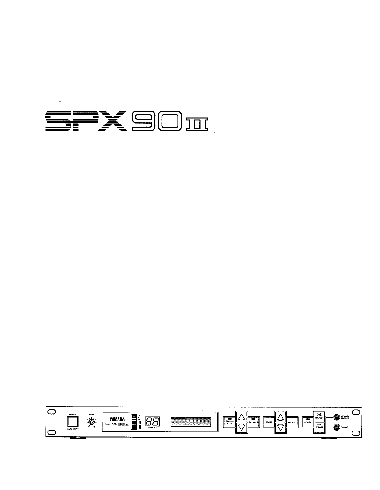
FRONT PANEL
Power ON/OFF Switch
When the power is turned ON, the program which
was selected immediately before the power was
turned OFF will be re-selected. Due to the safety
muting circuit, no sound will be produced by the
SPX90 II for a few seconds after the power is
turned ON.
Input Level Control (0 ~ 10)
Regulates the level of the input signal. Set the INPUT LEVEL control while watching the INPUT LEVEL
meter. The seven LED meter segments should not
all be continuously on when an input signal is applied, as this will result in input amplifier overload
and distortion. When the INPUT LEVEL control is set
to “8” on the scale, the input/output gain is 1
(unity). A setting of “10” increases gain by about
10 dB.
Input Level Meter
This easy-to-read LED level meter is a visual aid to
setting appropriate input levels. Generally, the best
input level setting will produce continuous lighting
of the lower green LED segments, while the upper
red segments flash only occasionally.
Memory Number LED
This LED display shows the number of the currently selected program. Memory numbers 1 through 30
contain factory-preset effects (ROM). Memory
numbers 31 through 90 can be used to store edited
versions of the preset effects (RAM).
LCD Program and Parameter Indicator
This high-contrast Liquid Crystal Display indicates
the effect name and parameter data value.
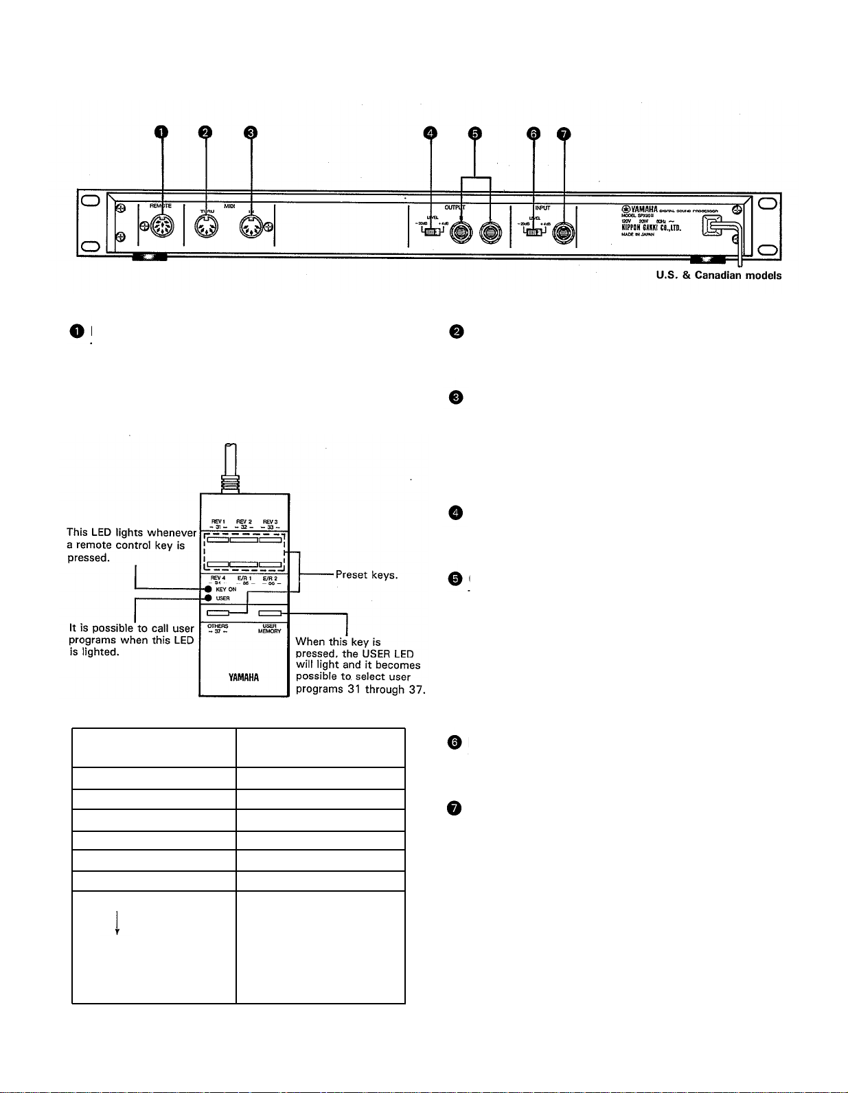
Parameter Key
Selects successive effect parameters. Pressing this
key sequentially calls the programmable parameters
within the currently selected effect program. Once
the desired parameter has been selected, the
PARAMETER INCREMENT/DECREMENT keys are
used to change the value of that parameter, thereby
modifying the effect. The parameters available for
each program are different: refer to the parameter
chart on page 24.
Parameter Increment/Decrement Keys
These keys are used to change the value of a
selected parameter. Press the increment key (up arrow) to increase the value, or the decrement key
(down arrow) to decrease the value.
Balance/Output Level Key
Adjusts proportion of effect signal to direct signal.
Pressing this key alternately causes the current
balance and output level values to be displayed on
the LCD. The Parameter Increment/Decrement keys
3
are then used to adjust the displayed values.
Store Key
Stores any edited preset effect in a selected RAM
memory position (31 ~ 90).
Memory Increment/Decrement Keys
These keys select any desired memory number to
call a specific program or store an edited program
in the user memory area. The selected memory
number is shown on the MEMORY NUMBER display.
When a new memory number is called, the
MEMORY number display will flash until either the
STORE or RECALL function is activated.
Recall Key
Press this key to recall the program that resides in
the selected memory number.
Utility Key
Multi-purpose key accesses MIDI control functions,
facilitates program title editing and sets footswitch
memory control range. See pages 8 and 9 for details.
Foot Trigger Key
When this key is pressed and its LED is ON, the
footswitch connected to the Memory/Trigger jack
functions as a foot trigger for the GATE and FREEZE
programs, rather than for memory selection.
Bypass Key
When this key is pressed, the effect signal is shut
off and only the direct signal will be output. Direct
signal level is affected by the INPUT LEVEL control
setting.
Memory/Trigger Footswitch Jack
Facilitates remote memory selection via optional
footswitch. The range of memory locations to be
recalled by the footswitch can be set with a Utility
program. When the foot trigger function (above) is
ON, the footswitch connected to this jack acts as
a trigger footswitch rather than memory control. Use
of a Yamaha FC5 Foot Controller is recommended.
Bypass Footswitch Jack
Facilitates foot control of the BYPASS function
described above. A Yamaha FC-5 Foot Controller is
recommended.
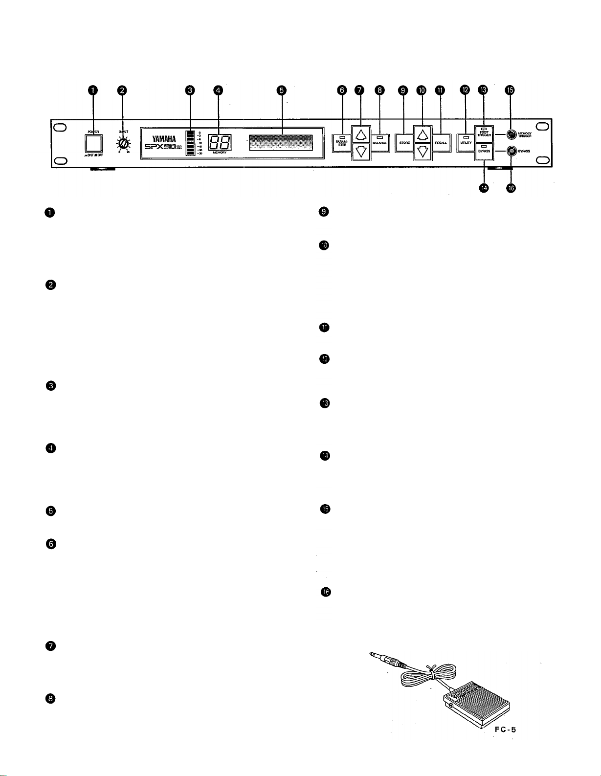
REAR PANEL
U.S. & Canadian models
Remote Control Connector
Permits remote access to SPX90 II effect programs.
The optional remote control unit, model RC7, permits direct access to programs 1 through 7 and 31
through 37, while all other preset programs may be
accessed sequentially.
MIDI THRU Connector
Re-transmits MIDI data received at the MIDI IN connector to subsequent MIDI instruments.
MIDI IN Connector
Permits SPX90 II effect programs to be automatical-
ly selected via a MIDI signal. This connector must
be connected to the MIDI OUT connector of the
transmitting MIDI instrument via a standard MIDI
cable.
Output Level Selector ( —20 db + 4 db)
Facilitates SPX90 II source/line level (sensitivity)
matching.
Output Jacks (L and R)
These are standard mono 1/4” phone jacks which
deliver the direct and effect signal to subsequent
mixing or amplification equipment. Since the
SPX90 II offers stereo output, we recommend that
the output signal be fed in stereo to a stereo sound
system in order to take full advantage of the superb
stereo effects provided. Output impedance is 600
ohms.
USER LED OFF
— Preset programs —
1. REV HALL 31. USER PROGRAM
2. REV 2 ROOM 32. USER PROGRAM
3. REV 2 VOCAL 33. USER PROGRAM
4. REV 4 PLATE 34. USER PROGRAM
5. EARLY REFLECTION 1
6. EARLY REFLECTION 2
7. DELAY L,R
30. PARAMETRIC EQ
(Programs 8 through 30)
selected sequentially by
pressing OTHERS/ -37key)
USER LED
— User programs —
35. USER PROGRAM
36. USER PROGRAM
37 USER PROGRAM
ON
Input Level Selector ( — 20 dB, + 4 dB)
Permits SPX90 II source/line level (sensitivity)
matching.
Input jack
This standard unbalanced mono 1/4” phone jack accepts the input signal to the SPX90 II. Input impedance is 10 k-ohms.
4
BASIC OPERATIONS
Before actually selecting or editing programs on your SPX90 II, make sure that all connections have been made
properly, and that the INPUT LEVEL switch, OUTPUT LEVEL switch, and INPUT LEVEL control have been properly
set according to the source signal and equipment to which the SPX90 II signal will be fed.
PRESET PROGRAM SELECTION
Your SPX90 II is equipped with a selection of 30
outstanding preset effect programs which are listed in
the ROM CONTENTS AND CONTROLABLE
PARAMETERS on page 24. The preset (and user) programs are selected as follows:
1. Use MEMORY INCREMENT/DECREMENT keys to
select desired memory number (remember, 1
through 30 are the presets).
2. Press RECALL key to call program in selected
memory number.
EDITING: CHANGING PARAMETERS
The SPX90 II offers incredible sonic flexibility, as each
effect type comprises its own set of parameters (see
parameter chart on page 24). These parameters can be
adjusted to suit your tastes and the tonal characteristics
of your musical equipment. We therefore recommend
that you examine each preset effect program, and
observe how these parameters affect the sound. You
will soon discover many new and exciting applications
for the SPX90 II’s preset effect programs.
1. Select and recall desired program as described
above.
2. Press PARAMETER key to access the various
parameters available in the selected program. Each
time the PARAMETER key is pressed, the next
parameter in the list is called.
NOTE: The same process is used to select user pro
grams (memory number 31 through 90) once
you have edited and stored your own programs
in user memory.
5
3. Use PARAMETER INCREMENT/DECREMENT keys
to set desired value of the selected parameter.
NOTE: A description of each parameter and its effect
will be given in the PROGRAMMABLE PARAMETERS section, beginning on page 10.
STORE: SAVING EDITED PROGRAMS
Once you’ve edited parameters on a preset program,
those changes will remain in effect only until you select
(RECALL) another program. The STORE function,
however, allows you to save the edited program in any
one of the user memory locations — from 31 to
90 — from which it can then be recalled at any time.
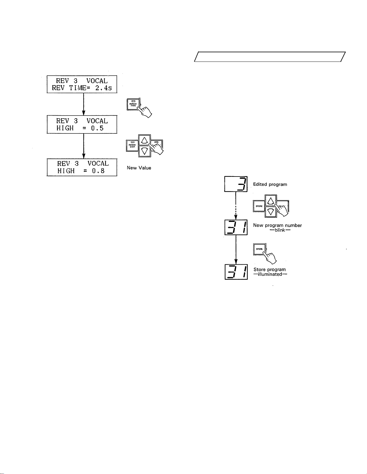
1. Select and edit a program as described above.
2. Use the MEMORY INCREMENT/DECREMENT keys
to select a clear memory location between 31 and
90.
3. Press the STORE key.
The edited program has now been stored in the selected
user memory location. The stored program may now
be recalled at any time by following the normal program
selection procedure.
NOTE: If you attempt to store a program in one of
the read-only preset locations (1 through 30),
the SPX90 II will display the “# 1 ~ # 30 READ
ONLY” error message.
: SPX90 II has an Edit Title Function, so you can
which allows you to provide your own titles for
edited programs. (See the UTILITY function on
page 8.)
6
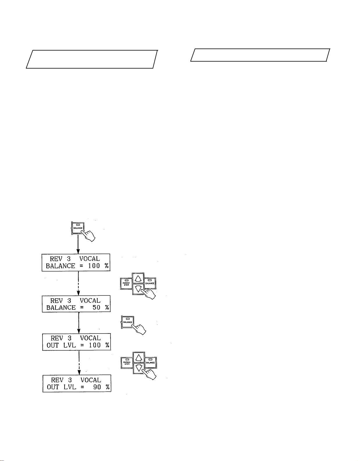
OUTPUT BALANCE AND LEVEL
PROGRAMMING
The BALANCE key selects the BALANCE and OUTPUT
LEVEL functions for all programs.
1. Press the BALANCE key while any parameter is
selected.
2. The first function called will be BALANCE. Adjust
the BALANCE of the effected and direct signal between 0 and 100% using the PARAMETER INCREMENT/DECREMENT keys.
* Balance = 100% : effect sound only.
Balance = 0% : direct sound only.
3. Press the BALANCE key again to call the OUTPUT
LEVEL function. Adjust using the PARAMETER INCREMENT/DECREMENT keys.
* OUT LVL = 100% : maximum output level.
OUT LVL = 0% : no sound will be output.
BYPASS
When the BYPASS key is pressed and its LED lights,
the effect signal is defeated and only the direct input
signal is delivered via the OUTPUT jacks. The BALANCE
and OUTPUT LEVEL functions are also bypassed.
The BYPASS function can also be activated via a
footswitch connected to the BYPASS jack. A normallyclosed-type footswitch such as the Yamaha FC-5 must
be used.
7
UTILITY FUNCTIONS
The UTILITY key provides access to four utility functions. These functions are selected in the following se-
quence each time the UTILITY key is pressed:
Normal mod
MlDl PROGRAM CHANGE FOOTSWITCH
MEMORY RECALL
The UTILITY key LED will light during selection of the
four utility functions, and will go out when the normal
mode is returned to. When the UTILITY LED is ON, the
PARAMETER and MEMORY NUMBER INCREMENT/
DECREMENT keys will perform special functions as
described below, so normal parameter and memory
selection can not be performed until the normal mode
is selected.
EDIT TITLE
Normal mode.
MIDl CONTROL
EDIT TITLE
This function makes it possible to provide new titles
for programs which you have edited and stored in user
memory (31 through 90). When the EDIT TITLE function is called, the lower line of the LCD will display the
“EDIT TITLE” function name, and the upper line will
display the title of the currently selected program.
The PARAMETER and BALANCE keys can then be used to move the cursor left and right, respectively, to
select the character to be changed. Place the cursor
over a character, then use the PARAMETER INCRE-
MENT/DECREMENT keys to scroll through the
character list, stopping at the desired character. Move
the cursor to the next character location and repeat this
operation until the new title is complete.
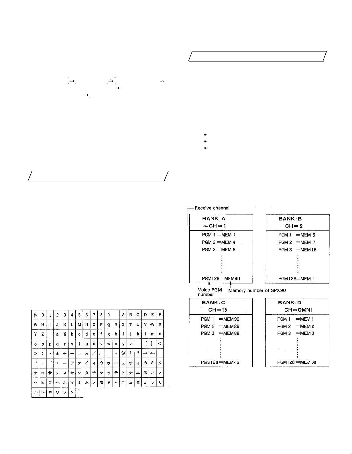
The available characters are as follows:
MIDI FUNCTIONS
With the SPX90 II it is possible to select specific programs via external MIDI control. For example, you can
set the SPX90 II so that when you select a specific
voice on your MIDI synthesizer, the most appropriate
effect program for that voice is selected automatically. In this case, the SPX90 II is detecting the MIDI
Program Change signal. For the following programs
only, the SPX90 II also detects the MIDI Note ON/OFF
signal:
GATE programs (GATE ON/OFF).
PITCH programs (sets pitch).
FREEZE programs (begin playback).
For MIDI program change operation, it is possible to program four independent sets of program change/memory
number combinations. These are referred to as “banks”
in the SPX90 II. For example, you could program the
four banks with different combinations as shown in the
chart below.
The second function accessed by the UTILITY key —
MIDI CNTRL — permits BANK selection and setting of
the MIDI channel number on which MIDI program
change data for that BANK will be received. The third
function accessed by the UTILITY key — MIDI PGM
CHANGE — makes it possible to set the SPX memory
number which will be called when a specific MIDI program change number is received.
8
 Loading...