

Basics SectionQuick GuideReferenceAppendix
SPECIAL MESSAGE SECTION
This product utilizes batteries or an external power supply (adapter). DO NOT
connect this product to any power supply or adapter other than one
described in the manual, on the name plate, or specifically recommended by
Yamaha.
WARNING:
Do not place this product in a position where anyone could walk on, trip over
,or roll anything over power or connecting cords of any kind. The use of an
extension cord is not recommended! IF you must use an extension cord, the
minimum wire size for a 25' cord (or less ) is 18 AWG. NOTE: The smaller the
AWG number ,the larger the current handling capacity. For longer extension
cords, consult a local electrician.
This product should be used only with the components supplied or; a cart,
rack, or stand that is recommended by Yamaha. If a cart, etc., is used, please
observe all safety markings and instructions that accompany the accessory
product.
SPECIFICATIONS SUBJECT TO CHANGE:
The information contained in this manual is believed to be correct at the time
of printing. However, Yamaha reserves the right to change or modify any of
the specifications without notice or obligation to update existing units.
This product, either alone or in combination with an amplifier and headphones
or speaker/s, may be capable of producing sound levels that could cause
permanent hearing loss. DO NOT operate for long periods of time at a high
volume level or at a level that is uncomfortable. If you experience any hearing
loss or ringing in the ears, you should consult an audiologist.
IMPORTANT: The louder the sound, the shorter the time period before
damage occurs.
Some Yamaha products may have benches and / or accessory mounting
fixtures that are either supplied with the product or as optional accessories.
Some of these items are designed to be dealer assembled or installed. Please
make sure that benches are stable and any optional fixtures (where
applicable) are well secured BEFORE using.
Benches supplied by Yamaha are designed for seating only. No other uses
are recommended.
NOTICE:
Service charges incurred due to a lack of knowledge relating to how a
function or effect works (when the unit is operating as designed) are not
covered by the manufacturer’s warranty, and are therefore the owners
responsibility. Please study this manual carefully and consult your dealer
before requesting service.
ENVIRONMENTAL ISSUES:
Yamaha strives to produce products that are both user safe and
environmentally friendly. We sincerely believe that our products and the
production methods used to produce them, meet these goals. In keeping with
both the letter and the spirit of the law, we want you to be aware of the
following:
Battery Notice:
This product MAY contain a small non-rechargeable battery which (if
applicable) is soldered in place. The average life span of this type of battery
is approximately five years. When replacement becomes necessary, contact a
qualified service representative to perform the replacement.
This product may also use “household” type batteries. Some of these may be
rechargeable. Make sure that the battery being charged is a rechargeable
type and that the charger is intended for the battery being charged.
When installing batteries, do not mix batteries with new, or with batteries of a
different type. Batteries MUST be installed correctly. Mismatches or incorrect
installation may result in overheating and battery case rupture.
Warning:
Do not attempt to disassemble, or incinerate any battery. Keep all batteries
away from children. Dispose of used batteries promptly and as regulated by
the laws in your area. Note: Check with any retailer of household type
batteries in your area for battery disposal information.
Disposal Notice:
Should this product become damaged beyond repair, or for some reason its
useful life is considered to be at an end, please observe all local, state, and
federal regulations that relate to the disposal of products that contain lead,
batteries, plastics, etc. If your dealer is unable to assist you, please contact
Yamaha directly.
NAME PLATE LOCATION:
The name plate is located on the rear of the product. The model number,
serial number, power requirements, etc., are located on this plate. You should
record the model number, serial number, and the date of purchase in the
spaces provided below and retain this manual as a permanent record of your
purchase.
Model
Serial No.
Purchase Date
92-BP (rear)
PLEASE KEEP THIS MANUAL

FCC INFORMATION (U.S.A.)
1. IMPORTANT NOTICE: DO NOT MODIFY THIS UNIT!
This product, when installed as indicated in the instructions contained in this manual, meets FCC requirements. Modifications not expressly approved by
Yamaha may void your authority, granted by the FCC, to use the product.
2. IMPORTANT:
When connecting this product to accessories and/or another product use only high quality shielded cables. Cable/s supplied with this product MUST be
used. Follow all installation instructions. Failure to follow instructions could void your FCC authorization to use this product in the USA.
3. NOTE:
This product has been tested and found to comply with the requirements listed in FCC Regulations, Part 15 for Class “B” digital devices. Compliance with
these requirements provides a reasonable level of assurance that your use of this product in a residential environment will not result in harmful interference
with other electronic devices. This equipment generates/uses radio frequencies and, if not installed and used according to the instructions found in the users
manual, may cause interference harmful to the operation of other electronic devices. Compliance with FCC regulations does not guarantee that interference
will not occur in all installations. If this product is found to be the source of interference, which can be determined by turning the unit “OFF” and “ON”, please
try to eliminate the problem by using one of the following measures:
Relocate either this product or the device that is being affected by the interference.
Utilize power outlets that are on different branch (circuit breaker or fuse) circuits or install AC line filter/s.
In the case of radio or TV interference, relocate/reorient the antenna. If the antenna lead-in is 300 ohm ribbon lead, change the lead-in to co-axial type cable.
If these corrective measures do not produce satisfactory results, please contact the local retailer authorized to distribute this type of product. If you can not
locate the appropriate retailer, please contact Yamaha Corporation of America, Electronic Service Division, 6600 Orangethorpe Ave, Buena Park, CA90620
The above statements apply ONLY to those products distributed by Yamaha Corporation of America or its subsidiaries.
* This applies only to products distributed by YAMAHA CORPORATION OF AMERICA.
(class B)
NEDERLAND / THE NETHERLANDS
• Dit apparaat bevat een lithium batterij voor geheugen back-up.
• This apparatus contains a lithium battery for memory back-up.
• Raadpleeg uw leverancier over de verwijdering van de batterij op het
moment dat u het apparaat ann het einde van de levensduur afdankt of
de volgende Yamaha Service Afdeiing:
Yamaha Music Nederland Service Afdeiing
Kanaalweg 18-G, 3526 KL UTRECHT
Tel. 030-2828425
• For the removal of the battery at the moment of the disposal at the end of
the service life please consult your retailer or Yamaha Service Center as
follows:
Yamaha Music Nederland Service Center
Address: Kanaalweg 18-G, 3526 KL UTRECHT
Tel: 030-2828425
• Gooi de batterij niet weg, maar lever hem in als KCA.
• Do not throw away the battery. Instead, hand it in as small chemical
waste.
(lithium disposal)
ADVARSEL!
Lithiumbatteri—Eksplosionsfare ved fejlagtig håndtering. Udskiftning m*
kun ske med batteri af samme fabrikat og type. Levér det brugte batteri
tilbage til leverandoren.
VARNING
Explosionsfara vid felaktigt batteribyte. Använd samma batterityp eller en
ekvivalent typ som rekommenderas av apparattillverkaren. Kassera använt
batteri enligt fabrikantens instruktion.
VAR OITUS
Paristo voi räjähtää, jos se on virheellisesti asennettu. Vaihda paristo
ainoastaan laitevalmistajan suosittelemaan tyyppiin. Hävit* käytetty paristo
valmistajan ohjeiden mukaisesti.
(lithium caution)
PRECAUTIONS
PLEASE READ CAREFULLY BEFORE PROCEEDING
* Please keep this manual in a safe place for future reference.
WARNING
Always follow the basic precautions listed below to avoid the possibility of serious injury or even death from electrical
shock, short-circuiting, damages, fire or other hazards. These precautions include, but are not limited to, the following:
Power supply/AC power adaptor
• Only use the voltage specified as correct for the instrument.
The required voltage is printed on the name plate of the
instrument.
• Use the specified adaptor (PA-5C or an equivalent
recommended by Yamaha) only. Using the wrong adaptor
can result in damage to the instrument or overheating.
• Check the electric plug periodically and remove any dirt or
dust which may have accumulated on it.
• Do not place the AC adaptor cord near heat sources such
as heaters or radiators, and do not excessively bend or
otherwise damage the cord, place heavy objects on it, or
place it in a position where anyone could walk on, trip over,
or roll anything over it.
Do not open
• Do not open the instrument or attempt to disassemble the
internal parts or modify them in any way. The instrument
contains no user-serviceable parts. If it should appear to be
malfunctioning, discontinue use immediately and have it
inspected by qualified Yamaha service personnel.
Water warning
• Do not expose the instrument to rain, use it near water or in
damp or wet conditions, or place containers on it
containing liquids which might spill into any openings.
• Never insert or remove an electric plug with wet hands.
Fire warning
• Do not put burning items, such as candles, on the unit.
A burning item may fall over and cause a fire.
If you notice any abnormality
• If the AC adaptor cord or plug becomes frayed or
damaged, or if there is a sudden loss of sound during use
of the instrument, or if any unusual smells or smoke should
appear to be caused by it, immediately turn off the power
switch, disconnect the adaptor plug from the outlet, and
have the instrument inspected by qualified Yamaha service
personnel.
CAUTION
Always follow the basic precautions listed below to avoid the possibility of physical injury to you or others, or damage to
the instrument or other property. These precautions include, but are not limited to, the following:
Power supply/AC power adaptor Location
• When removing the electric plug from the instrument or an
outlet, always hold the plug itself and not the cord.
• Unplug the AC power adaptor when not using the
instrument, or during electrical storms.
• Do not connect the instrument to an electrical outlet using a
multiple-connector. Doing so can result in lower sound
quality, or possibly cause overheating in the outlet.
• Do not expose the instrument to excessive dust or
vibrations, or extreme cold or heat (such as in direct
sunlight, near a heater, or in a car during the day) to prevent
the possibility of panel disfiguration or damage to the
internal components.
• Do not use the instrument in the vicinity of a TV, radio,
stereo equipment, mobile phone, or other electric devices.
Otherwise, the instrument, TV, or radio may generate noise.
• Do not place the instrument in an unstable position where it
might accidentally fall over.
• Before moving the instrument, remove all connected
adaptor and other cables.
• Use only the stand specified for the instrument. When
attaching the stand or rack, use the provided screws only.
Failure to do so could cause damage to the internal
components or result in the instrument falling over.
(3)-7 1/2

Connections
• Before connecting the instrument to other electronic
components, turn off the power for all components. Before
turning the power on or off for all components, set all
volume levels to minimum. Also, be sure to set the volumes
of all components at their minimum levels and gradually
raise the volume controls while playing the instrument to
set the desired listening level.
Backup battery
• This instrument has a built-in lithium backup battery. When
you unplug the power cord from the AC outlet, the internal data
is retained. However, if the backup battery fully discharges,
this data will be lost. When the backup battery is running
low, the LCD indicates “!BatteryLo.” In this case,
immediately save the data to a Memory Card
(SmartMedia), then have qualified Yamaha service
personnel replace the backup battery.
Maintenance
• When cleaning the instrument, use a soft, dry cloth. Do not
use paint thinners, solvents, cleaning fluids, or chemicalimpregnated wiping cloths.
Handling caution
• Do not insert a finger or hand in any gaps on the instrument.
• Never insert or drop paper, metallic, or other objects into
the gaps on the panel or keyboard. If this happens, turn off
the power immediately and unplug the power cord from the
AC outlet. Then have the instrument inspected by qualified
Yamaha service personnel.
• Do not place vinyl, plastic or rubber objects on the
instrument, since this might discolor the panel or keyboard.
• Do not rest your weight on, or place heavy objects on the
instrument, and do not use excessive force on the buttons,
switches or connectors.
• Do not operate the instrument for a long period of time at a
high or uncomfortable volume level, since this can cause
permanent hearing loss. If you experience any hearing loss
or ringing in the ears, consult a physician.
Saving data
Saving and backing up your data
• Any edited data (see pages 33 and 40) that is left un-stored
will be lost if you turn off the power to the instrument. Save the
data to the USER memory (see page 50).
• USER memory data (see page 20) is retained when the
power is turned off, as long as the backup battery retains a
charge. However, the data could be lost due to malfunction
or incorrect operation. Save important data to a Memory
Card (SmartMedia).
Backing up the Memory Card (SmartMedia)
•To protect against data loss through media damage, we
recommend that you save your important data onto two
Memory Cards (SmartMedia).
Yamaha cannot be held responsible for damage caused by improper use or modifications to the instrument, or data that is lost
or destroyed.
Always turn the power off when the instrument is not in use.
Even when the power switch is in the “STANDBY” position, electricity is still flowing to the instrument at the minimum level.
When you are not using the instrument for a long time, make sure you unplug the AC power adaptor from the wall AC outlet.
Make sure to discard used batteries according to local regulations.
(3)-7 2/2
Introduction
Thank you for purchasing the Yamaha S08 Music Synthesizer. In order to get the most out of your new S08 and its
sophisticated functions, we suggest you read through this manual thoroughly. Also keep it in a safe, convenient place
so that you can regularly refer to it when necessary.
Package Contents
• PA-5C AC Adaptor * • CD-ROM •Installation Guide
• Owner’s Manual • Data List
* May not be included in your area. Please check with your Yamaha dealer.
About the Included CD-ROM
Application software for your S08 is included on this CD-ROM. The Voice Editor lets you edit the Voices of the S08
with a highly intuitive graphical interface. With the included sequencing software (Windows only), you can easily
create and edit your own original songs on your computer. For details, refer to the separate Installation Guide or the
on-line manual included with the software.
Never attempt to play back the CD-ROM on an audio CD player. Doing so may result in damage to your hearing as well as
to your CD player/audio speakers.
Main Features
•Exceptionally high-quality dynamic Voices — including many sounds from Yamaha’s top-of-the-line S80 Music
Synthesizer (page 16).
• Naturally responsive 88-key Balanced Hammer Effect keyboard, drawing on our extensive experience and
expertise in piano-making.
• Wide variety of pro-quality digital effects (page 46).
• Category Search function for quickly calling up Voices in a desired instrument group (page 31).
•A total of 493 Normal Voices and 29 Drum Voices, all GM2/XG-compatible — in addition to Preset Voices and
User Voices (page 20).
• Memory cards, which let you easily organize and archive the internal data (page 53).
• Sequence Play function, that lets you directly play song files stored to memory cards (page 51).
• Comprehensive, detailed editing features for customizing your Voices (page 40 and 58).
• Convenient USB terminal for direct, easy connection to computer — with just one cable (page 14).
GM System Level 1
“GM System Level 1” is a standard specification that defines the arrangement of voices in a tone generator and its MIDI
functionality, ensuring that data can be played back with substantially the same sounds on any GM-compatible tone
generator, regardless of its manufacturer or model. Tone generators and song data that meet the “GM System Level 1” bear
this GM logo.
GM System Level 2 (GM2)
“GM System Level 2” is a standard specification that enhances the original “GM System Level 1” and improves song data
compatibility. It provides for increased polyphony, greater voice selection, expanded voice parameters, and integrated effect
processing. Tone generators and song data that meet the “GM System Level 2” specifications bear this GM2 logo.
XG
“XG” is a tone generator format that expands the voice arrangement of the “GM System Level 1” specification to meet the
ever-increasing demands of today’s computer peripheral environment, providing richer expressive power while maintaining
upward compatibility of data. “XG” greatly expands “GM System Level 1” by defining the ways in which voices are expanded
or edited and the structure and type of effects.
When commercially available song data bearing the XG logo is played back on a tone generator which bears the XG logo, you
will enjoy a full musical experience that includes unlimited expansion voices and effect functions.
USB
USB is an abbreviation for Universal Serial Bus. It is a serial interface for connecting a computer with peripheral devices.
It allows “hot swapping” (connecting peripheral devices while the power to the computer is on).
6
About This Manual
This manual consists of the following sections.
■ Basics Section (page 11)
This section provides a overview of the main functions and features of the S08 and introduces you to the basic
operating conventions.
■ Quick Guide (page 29)
This section explains how to use the basic functions.
■ Reference : Function List (page 58)
The S08 encyclopedia. This section explains all parameters.
■ Appendix (page 72)
This section contains detailed information on the S08 such as MIDI, Display Messages, Troubleshooting and
Specifications.
■ Installation Guide (separate booklet)
Refer to this for instructions on installing the included software programs (on the CD-ROM) to your computer.
■ Data List (separate booklet)
This contains various important lists such as the Voice List, Wave List, Multi List, and MIDI Implementation
Chart.
About the “Page” References in this Manual
PAGE xx ..... Refers to a display “page” in the LCD
page xx........ Refers to an actual page in this manual.
Many of the functions and parameters of the S08 are shown on various display “pages,” each of which is numbered
within each mode and indicated in the display. Searching for a function or parameter is made more convenient and
fast by the use of these page numbers.
To distinguish these display page references from actual pages in the manual, we’ve applied the following convention:
“PAGE” (all capital letters) refers to the display page. Unless indicated otherwise, the PAGE reference is for display
pages within the same mode (as described for other parameters in the same section).
Throughout the manual, parameter names are prefaced by numbers, such as “13-2 Resonance.” This, for example,
indicates that the Resonance parameter is on display PAGE 13 in the selected mode.
When one display page contains two or more related parameters, use the [ ]/[ ] buttons (page 26) to scroll
through the available parameters. These related parameters selected by the [ ]/[ ] buttons are indicated by
hyphenated numbers (e.g., 13-1, 13-2, etc.). In the example above, you can select the Resonance parameter by using
the [ ]/[ ] buttons to move to the second page.
n For a full listing of the parameters and their corresponding display pages, refer to the Function List (page 58) or the
Parameter Table (page 18).
● Copying of the commercially available music sequence data and/or digital audio files is strictry prohibited except
for your personal use.
● The illustrations and LCD screens as shown in this owner’s manual are for instructional purposes only, and may
appear somewhat different from those on your instrument.
● The company names and product names in this Owner’s Manual are the trademarks or registered trademarks of
their respective companies.
7

Application Index
This convenient, easy-to-use index is divided to general categories to help you when you want to find information on
a specific topic or function.
Listening/Playing
■
• Listening to Demo songs ................................................................................................................................... Demo Playback (Page 16)
• Playing the voices .......................................................................................................................................................................... (Page 29)
• Calling up Voices in a desired instrument group ........................................................................ Using Voice Category Search (Page 31)
• Playing songs from memory cards................................................................................................................................................ (Page 51)
• Assigning songs to each chain step automatically....................................................................................................................... (Page 52)
• Converting Standard MIDI file from format 1 to format 0..... the separate Installation Guide and the Card Filer Owner’s Manual (PDF)
• Performing live while playing back a Song file ........................................................................................................................... (Page 34)
• Splitting the keyboard — Setting upper and lower ranges for the Voices
- In Multi mode............................................................................................................................................................................. (Page 34)
- In Voice mode ........................................................................................................................................................... Note Limit (Page 59)
• Layering two voices (Parts together)............................................................................................................................................ (Page 35)
• Changing the keyboard played part in the Multi mode ...............................................................................................Trans Ch (Page 66)
• Selecting the touch sensitivity (Global setting) ......................................................................................................................... (Page 57)
• Changing the volume response to your playing strength - getting high volume from soft playing or soft volume from strong playing
(for each Voice/Multi).......................................................................................................................VelSnsDpt/VelSnsOfs (Pages 58, 64)
■ Using controllers
• Connecting controllers .................................................................................................................................................................. (Page 15)
• Setting the Pitch Bend Range............................................................................................................................... PB Range (Pages 58, 65)
• Using a Foot Controller/Footswitch to control parameters ........................................................................................................ (Page 38)
• Using a Footswitch to start/stop the sequencer........................................................................................................................... (Page 38)
• Using a Footswitch to advance through Voice or Multi programs.............................................................................................. (Page 38)
• Maintaining the controller state/position when you switch between voices ................................................ Controller Reset (Page 67)
• Setting the AC1 (Assignable Controller 1) Controller .........................................................................................................(Pages 37, 38)
• Controlling the effect depth
- MW (Modulation wheel settings) ...................................................................................................................MW VarCtl (Pages 59, 64)
- AC1 (Assignable controller 1 ) settings..........................................................................................................AC1 VarCts(Pages 59, 64)
■ Copying
• Copying the Voice Variation Effect settings to the Multi mode ............................................................. Copy Variation Effect (Page 49)
• Copying the Controller settings of the Voice mode to the Multi mode............................................................Copy Controller (Page 49)
• Copying Element parameter settings of the Voice being edited to another Element in the same Voice................................... (Page 48)
• Copying Part parameter settings of the Multi being edited to another Part in the same Multi ................................................ (Page 49)
• Backing up your S08 data ..............................................Saving S08 Settings to an External Device/Saving the Settings (Pages 36, 50)
■ Changing the sound
• Editing a Voice ............................................................................................................................................................. Voice Edit (Page 40)
• Effect structure and signal flow........................................................................................................................................Effects (Page 46)
• Editing the effect settings................................................................................................................. Example of Effect Settings (Page 46)
• Adjusting the Voice sustain..........................................................................................................................................AEGRelR (Page 61)
• Getting a brighter sound ....................................................................................................................................................Cutoff (Page 43)
• Getting a more pronounced effect ............................................................................................................................. Resonance (Page 43)
• Simulating monophonic instruments................................................................................................................Mono/Poly (Pages 58, 64)
• Setting the stereo pan position................................................................................................................................. Pan (Pages 59, 62, 63)
• Changing the Element/Part that is sounded according to the velocity................................................................................... VelLmt-L/H
In Voice Mode................................................................................................................................................................................ (Page 59)
In Multi Mode................................................................................................................................................................................ (Page 64)
• Getting a smooth transition in pitch from one note to the next............................................................... Porta Sw/Time (Pages 58, 65)
■ Changing the pitch
• Transposing the sound/Adjusting the pitch (tone generator settings)
- Voice (Element ) settings ............................................................................................................................. Note Shift/Detune(Page 59)
- Multi (Part) settings.................................................................................................................................... Note Shift/Detune (Page 64)
- Multi (Common) settings .........................................................................................................................................Transpose (Page 63)
• Transposing the keyboard.......................................................................................................................................... Kbd Trans (Page 67)
• Adjust the tuning to other instruments ..................................................................................................................MasterTune (Page 66)
• Setting the all notes (keys) to the same pitch ............................................................................................................ PchSclSns (Page 59)
8
Application Index

■ Setting the volume/level
• Adjusting the total volume................................................................................................................................ VOLUME slider (Page 12)
• Adjusting the Multi volume (affects all parts)............................................................................................................. Total Vol (Page 63)
• Adjusting each part’s volume...........................................................................................................................................Volume (Page 64)
• Adjusting the Voice volume (affects all elements)................................................................................................ Total Lvl/Vol (Page 63)
• Adjusting each element’s volume....................................................................................................................................... Level (Page 59)
• Adjusting each drum key’s volume..................................................................................................................................... Level (Page 62)
■ Setting the sound of a drum voice
• Moving the pan position randomly each time a key is pressed............................................................................................ Pan (Page 62)
• Setting the drum key for independent open and closed hi-hat sounds ...................................................................Alt. Group (Page 62)
• Setting the key release response: Enabling a sound to decay naturally even when a key is released,
or having the sound cut off when key is released.....................................................................................................RxNoteOff (Page 62)
• Disabling the sound for specific instruments in a drum kit..................................................................................... RxNoteOn (Page 62)
■ Selectively disabling sounds
• Keeping certain elements from sounding temporarily during editing........................................................Mute function (Pages 41, 42)
• Disabling the sound of specific elements................................................................................................................. Element Sw (Page 59)
• Keeping certain parts from sounding temporarily.............................................................................................. Mute function (Page 41)
• Disabling the sound of specific parts................................................................................................................................ RcvCh (Page 64)
• Disabling the sound of specific keys (instrument sounds) in a drum kit...............................................................Rx NoteOn (Page 62)
■ Convenient editing functions
• Monitoring an Element for Editing.............................................................................................................................................. (Page 42)
• Creating a completely new Voice/Multi from scratch ................................................................................................................ (Page 48)
• Listening to the difference between the Voice/Multi with your edited settings
and the same Voice/Multi prior to editing ................................................................................................... Compare Function (Page 41)
■ Entering data
• Entering the value directly with the numeric keypad or the keyboard...................................................................................... (Page 28)
• Entering characters (Voice/Multi/File Name Settings)............................................................................................................. (Page 50)
■ Saving data
• Storing the edited Voice/Multi to the S08’s internal (USER) memory...................................................................................... (Page 50)
• Saving S08 settings (Voice/Multi/MIDI/Utility) to an external device such as a computer or Memory Card................ (Pages 36, 54)
■ Connecting the S08 to other devices
• Connecting a computer .......................................................................................................... Connecting a Personal computer (Page 14)
• Setting Local On/Off ...................................................................................................................................... Local On/Off (Pages 15, 67)
• Using the S08 as a multitimbral tone generator .......................................................................................................................... (Page 33)
• Sending the S08 data using the Bulk Dump function .......................................... Saving S08 Settings to an External Device (Page 36)
• Editing Voices using a computer..................................The separate Installation Guide and S08 Voice Editor Owner’s Manual (PDF)
• Using the included sequencing software (Windows only).............The separate Installation Guide and the application’s on-line help
• Setting the S08 to either receive or ignore program changes (Voice/Multi) from an external device..... RxPgmChng/RxBankSel (Page 66)
• Determining whether or not the S08 sends program changes to an external device.......................TxPgmChng/TxBankSel (Page 66)
• Determining whether or not an external sequencer starts/stops when starting/stopping the S08’s sequencer............ SeqCtl (Page 66)
• Determining whether or not the S08’s sequencer starts/stops when starting/stopping an external sequencer............ SeqCtl (Page
■ Resetting parameters (Initializing)
• Initializing Voice/Multi parameters.............................................................................................................................. Initialize (Page 48)
• Initializing chain step parameters ................................................................................................................................... InitSeq (Page 52)
• Formatting Memory Card.............................................................................................................................................................. (page 55)
• Resetting the S08 to its default settings....................................................................... Factory Set (Restore Factory Defaults) (Page 23)
■ Quick solutions and reference materials
• Global functions of the Function List .......................................................................................................................................... (Page 58)
• S08 parameter structure and the LCD PAGES ................................................................................................ Parameter Table (Page 18)
• Display Indications........................................................................................................................................................................ (Page 25)
• Memory Structure — indicating where various settings are stored ........................................................................................... (Page 20)
• Voice Structure - examining which elements are used in the voices .................... Checking the Voice Structure and Muting (Page 42)
• Parameters that are not effective for drum-voice-assigned parts................................................................................................ (Page 22)
• Explanation of Effect Types ................................................................................................................................... The separate Data List
• Lists of the Voices, Multis, Waves, Original Kits, etc............................................................................................. The separate Data List
• General information on MIDI ................................................................................................................................ About MIDI (Page 72)
• Meaning of the display messages.................................................................................................................... Display Messages (Page 77)
• Troubleshooting............................................................................................................................................................................ (Page 78)
66
)
Application Index
9

Table of Contents
Basics Section .........................11
The Controls & Connectors ............................................. 11
Top Panel ..................................................................................11
Rear Panel ................................................................................. 11
Before Use .......................................................................... 12
Power Supply ............................................................................ 12
Power-on Procedure ..................................................................12
Turning on the S08 .................................................................... 12
Connections ....................................................................... 13
Demo Playback .................................................................. 16
Overview of the S08 .......................................................... 16
Controller .................................................................................. 17
Tone Generator .........................................................................17
Effects ....................................................................................... 17
Card Drive/Sequencer ...............................................................17
Parameter Table ................................................................ 18
Voices & Multis................................................................. 20
Memory Structure ..................................................................... 20
Overview of Voice/Element/Multi ........................................... 21
Normal Voices & Drum Voices ................................................ 22
Part Mode Setting .....................................................................22
Factory Set (Restore Factory Defaults) ........................... 23
Basic Operations ...............................................................24
Modes ................................................................................. 24
Mode Table ........................................................................ 24
Selecting a Mode ............................................................... 24
Display Indications ........................................................... 25
Selecting a Screen .............................................................. 26
Entering Data .................................................................... 27
Quick Guide ...........................29
Voice Edit ........................................................................... 40
Effects ................................................................................. 46
Effects in Voice Mode .............................................................. 47
Effects in Multi Mode............................................................... 47
Using the Jobs .................................................................... 48
Saving the Settings (Store) ............................................... 50
Playing the Songs .............................................................. 51
Using the Memory Card ................................................... 53
Touch Sensitivity ............................................................... 57
Reference................................58
Voice Edit (Normal) .................................................................. 58
Voice Edit (Drum)..................................................................... 62
Voice Job ................................................................................... 63
Voice Store ................................................................................ 63
Multi Edit................................................................................... 63
Multi Job.................................................................................... 65
Multi Store................................................................................. 66
Sequence Play............................................................................ 66
Sequence Play Job ..................................................................... 66
Utility......................................................................................... 66
Utility Job .................................................................................. 67
Controller................................................................................... 67
Card ........................................................................................... 67
Appendix ...............................72
About MIDI ....................................................................... 72
Display Messages ............................................................... 77
Troubleshooting ................................................................ 78
Specifications ..................................................................... 83
Index ................................................................................... 84
Playing Voices ................................................................... 29
Using Multi Mode ............................................................. 32
Playing in Multi Mode .............................................................. 32
Using the S08 as a Multitimbral Tone Generator (Multi Edit) .33
Layering Two Voices (Parts) Together ..................................... 35
Using Controllers .............................................................. 37
Pitch Bend Wheel & Modulation Wheel ..................................37
Foot Controller .......................................................................... 38
Foot Switch ............................................................................... 38
10
Basics Section
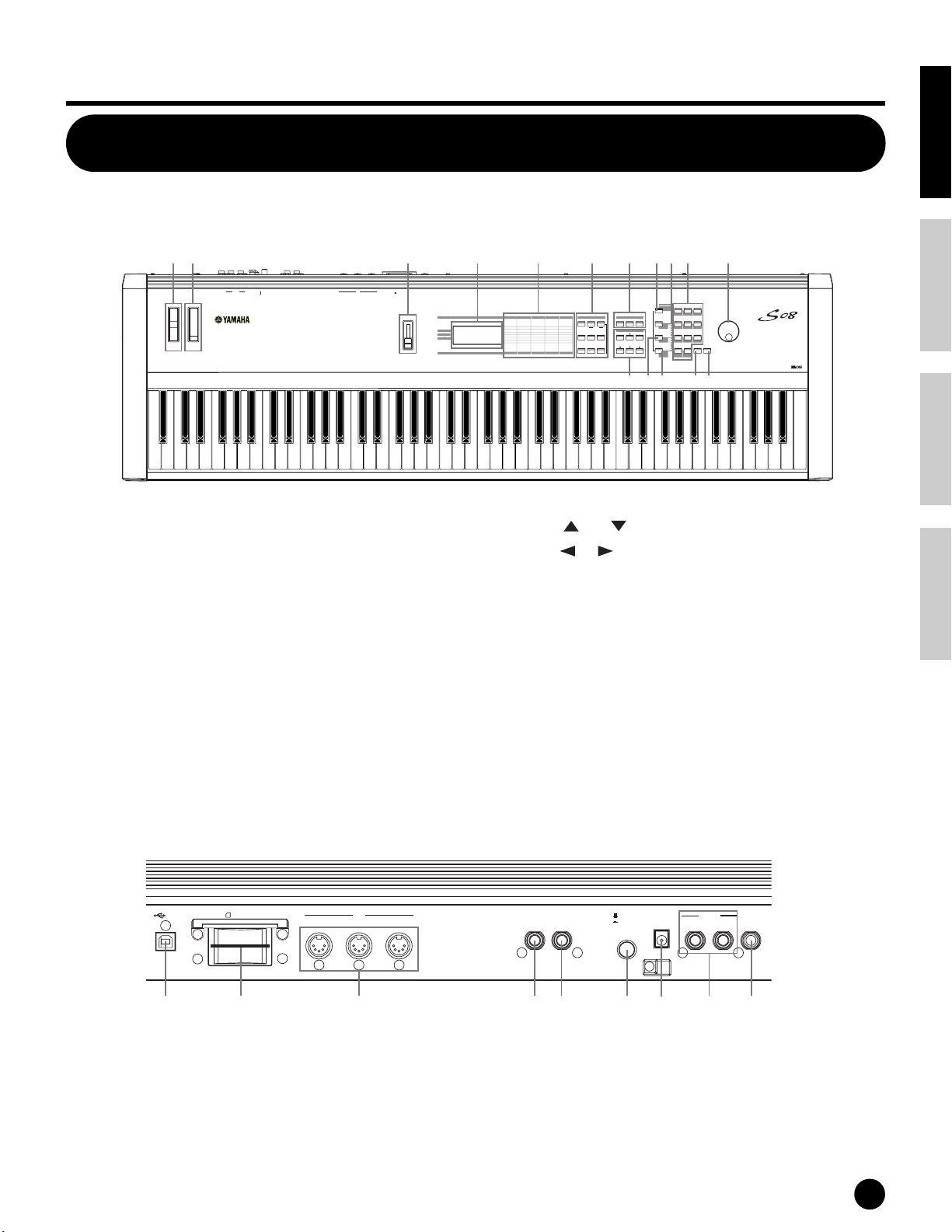
The Controls & Connectors
Top Panel
STANDBY
OUTPUT
L/MONO
PHONES
PITC
H
M
ODULATION
A-1 B-1 C0 D0 E0 F0 G0 A0 B0 C1 D1 E1 F1 G1 A1 B1 C2 D2 E2 F2 G2 A2 B2 C3 D3 E3 F3 G3 A3 B3 C4 D4 E4 F4 G4 A4 B5 C5 D5 E5 F5 G5 A5 B5 C6 D6 E6 F6 G6 A6 B6 C7
R DC IN ON
FOOT
FOOT
CONTROLLER
SWITCH
MIDI
IN OUT THRU
Basics SectionQuick GuideReferenceAppendix
32145679)#^
3.3V
USB
CARD
MODE
MULTI SEQ PLAY
VOICE
UTILITYCONTROLLER CARD
JOB
EDIT
COMPARE
PART/ELEMENT/KEY
+—
COMMON
DEMO
DATA
STORE
PLAY/STOP
CONTROLLER
M
E
VOLU
UTILITY
CARD
CONTROLLER
PART/
COMMON
VOICE
MIX
GENERAL
TONE
CONTROLLER
EFFECT
CARDUTILITYEDIT
ELEMENT
TG
OSC/MIX
CTRL ASSIGN
SAVE
PITCH
KEYBOARD
MIDI CHANNEL
LOAD
RENAME
VELOCITY
FILTER
MIDI FILTER
AMP
CTRL SETUP
SEQ SETUP
DELETE
MIDI SETUP
FORMAT
LFO
EFFECT
EFFECT
IMPORT
7
89
CATEGORY
DRUM
SEARCH
PRESET
4
MUTE
INC/YESDEC/NO
56
DRUM/PERC
BASS STRINGS BRASS
USER
2
1
REED/PIPE
SYN LEAD
SE
—
GM2/XG
0
OTHER
SYN COMP
CHROMATIC
PERCUSSION
MUSIC SYNTHESIZER
GUITARORGANPIANO
3
SYN PAD
EXITENTER
KEYBOARD
8$@!%
1 PITCH bend wheel (page 37)
2 MODULATION wheel (page 37)
3 [VOLUME] Slider (page 12)
4 LCD (Liquid Crystal Display)(page 24)
5 Parameter Type List (page 26)
6 MODE buttons (page 24)
7 [PART/ELEMENT/KEY] buttons
7-1 [+]/[–] buttons (page 26)
7-2 [MUTE] button (pages 41, 42)
8 DATA buttons (page 26)
8-1 [DEC/NO] button (page 27)
Rear Panel
3.3V
USB
CARD
THRU
8-2 [INC/YES] button (page 27)
8-3 [ ]/[ ] buttons (page 26)
8-4 [ ]/[ ] buttons (page 26)
9 [CATEGORY SEARCH/DRUM] button (pages 30, 31)
) [PRESET/(DRUM/PERC)] button (pages 29, 31)
! [USER/(SE)] button (pages 29, 31)
@ [GM2/XG/(OTHER)] button (pages 29, 31)
# Numeric keypad (pages 28, 30)
$ [ENTER/KEYBOARD] button (page 28)
% [EXIT] button (page 27)
^ Data Dial (page 27)
FOOT
MIDI
IN
OUT
FOOT
SWITCH
CONTROLLER
STANDBY
ON
DC IN
R
OUTPUT
L/MONO
PHONES
&* ( º¡™£¢∞
& USB terminal (page 14)
* Memory Card slot (page 53)
( MIDI IN/OUT/THRU terminals (pages 13)
º FOOT SWITCH jack (pages 15, 38)
¡ FOOT CONTROLLER jack (pages 15, 38)
™ STANDBY/ON switch (page 12)
£ DC IN terminal (page 12)
¢ OUTPUT L/MONO and R jack (page 13)
∞ PHONES jack (page 13)
n Host Select parameter is set in the Utility mode (page13).
The Controls & Connectors
11
Basics Section Quick Guide Reference Appendix
T
DC IN
ON
FOOT
CONTROLLER
FOOT
SWITCH
STANDBY
PHONES
L/MONO
R
OUTPUT
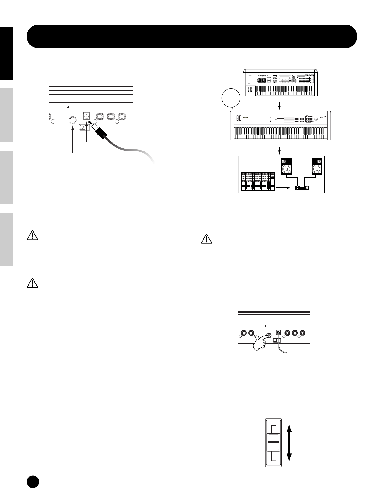
Before Use
Power Supply
Rear Panel
LLER
STANDBY
ON
DC IN
DC IN
STANDBY/ON switch
1 Make sure that the S08’s STANDBY/ON switch is
at the STANDBY (off) position.
2 Connect the PA-5C’s DC plug to the S08’s DC IN
terminal on the instrument’s rear panel.
3 Connect the adaptor’s AC plug to the nearest
electrical outlet.
Do not attempt to use an AC adaptor other than the
Yamaha PA-5C or an equivalent recommended by
Yamaha. The use of an incompatible adaptor may cause
irreparable damage to the S08, and may even pose a
serious shock hazard! ALWAYS UNPLUG THE AC
ADAPTOR FROM THE AC POWER OUTLET WHEN
THE S08 IS NOT IN USE.
Even when the switch is in the “STANDBY” position,
electricity is still flowing to the instrument at a minimum
level. When not using the S08 for an extended period of
time, be sure to unplug the AC power adaptor from the
wall AC outlet.
R
OUTPUT
L/MONO
PHONES
To electrical
outlet
When using the S08 as MIDI slave:
PAN
CHORUS
REVERB
TEMPO
ATTACK RELEASECUTOFF
RESONANCE
KNOB
REMOTE
POWER
ON!!
ASSIGN AASSIGN B ASSIGN 1 ASSIGN 2
CONTROL
CONTROL
FUNCTION
ON/OFF
MODE
KN 1 KN 2 KN 3 KN 4
VOICEPERFORM MASTER
MEQ LOW
MEQ HI MIDMEQLOWMID MEQ HIGH
ARPEGGIO
EFFECT BYPASS
SYSTEM
ON/OFF
INSERTION
MASTER
VOLUME 1VOLUME 2 VOLUME 3VOLUME 4
VOLUME
SEQUENCER
SONG
FILE
PATTERN
SEQ
TRANSPORT
INTEGRATED
SAMPLING
UTILITY
MIXING
SONG SCENE
SF 1SF 2SF 3SF 4SF 5
2
LOCATE
1
REC
EDIT
STORE
JOB
F1 F2 F3 F4 F6F5
SCENE STORE
COMPARE
SET LOCATE
CS 1 CS 2 CS 3 CS 4
OCTAVE
UP
DOWN
ZONE 1 ZONE 2 ZONE 3 ZONE 4
MIDI master (transmitting device)
MUSIC
SYNTHESIZER
PRODUCTION
Sequencer
Sampling
Integrated
Real-timeExternalControl
Surface
Modular
SynthesisPlug-in
System
SLOT 1 SLOT 2 SLOT 3
CATEGORY
PRE 2
PRE 1
PRE 3
PLG 3
PLG 2
DRUM KITS
USER PLG 1
GM
SEARCH
BANK
GUITAR/
BRASS
KEYBOARD
STRINGS
A. PIANO
REED/PIPE
ORGAN
BASS
FAVORITES
PLUCKED
COMMON
D
B
E
SECTION
A
C
FGH
DEC/NO INC/YES
INFORMATION
EXIT
GROUP
DRUM/
SYN COMPCHROMATIC
SE
SYN LEADSYN PAD/
MUSICAL FXCOMBI
PERCUSSION
PERCUSSION
CHOIR
TRACK
1234
567
8
SELECT
ELEMENT/PERF.PART/ZONE
NUMBER
11
12
10
131416
9
ENTER
15
MUTE
EXECUTE
SOLO
MUSIC SYNTHESIZER
S08 as MIDI slave (MIDI receiving device)
12345678910111213141516LR
Audio equipment (first mixer, then amplifier)
Turning on the S08
In order to avoid possible damage to the speakers or other
connected electronic equipment, always switch on the
power of the S08 before switching on the power of the
amplified speakers or mixer and amplifier. Likewise,
always switch off the power of the S08 after switching off
the power of the amplified speakers or mixer and
amplifier.
n Before you switch your S08 on or off, first turn down the
volume of any connected audio equipment.
1 Press the STANDBY/ON switch.
Power-on Procedure
When you have made all the necessary connections
between your S08 and any other devices (page 13),
make sure that all volume settings are turned down all
the way to zero. Then turn on every device in your
setup in the order of MIDI masters (senders), MIDI
slaves (receivers), then the audio equipment (mixers,
amplifiers, speakers, etc.). This ensures smooth MIDI
operation and prevents speaker damage.
When powering down the setup, first turn down the
volume for each audio device, then switch off each
device in the reverse order (first audio devices, then
MIDI).
12
Before Use
A splash screen (“Welcome to S08”) is displayed
briefly. The Multi or Voice Play Mode screen
appears next.
2 Turn up the amplifier’s volume as necessary.
3 Adjust the S08’s [VOLUME] slider to set an
appropriate volume level.
VOLUME
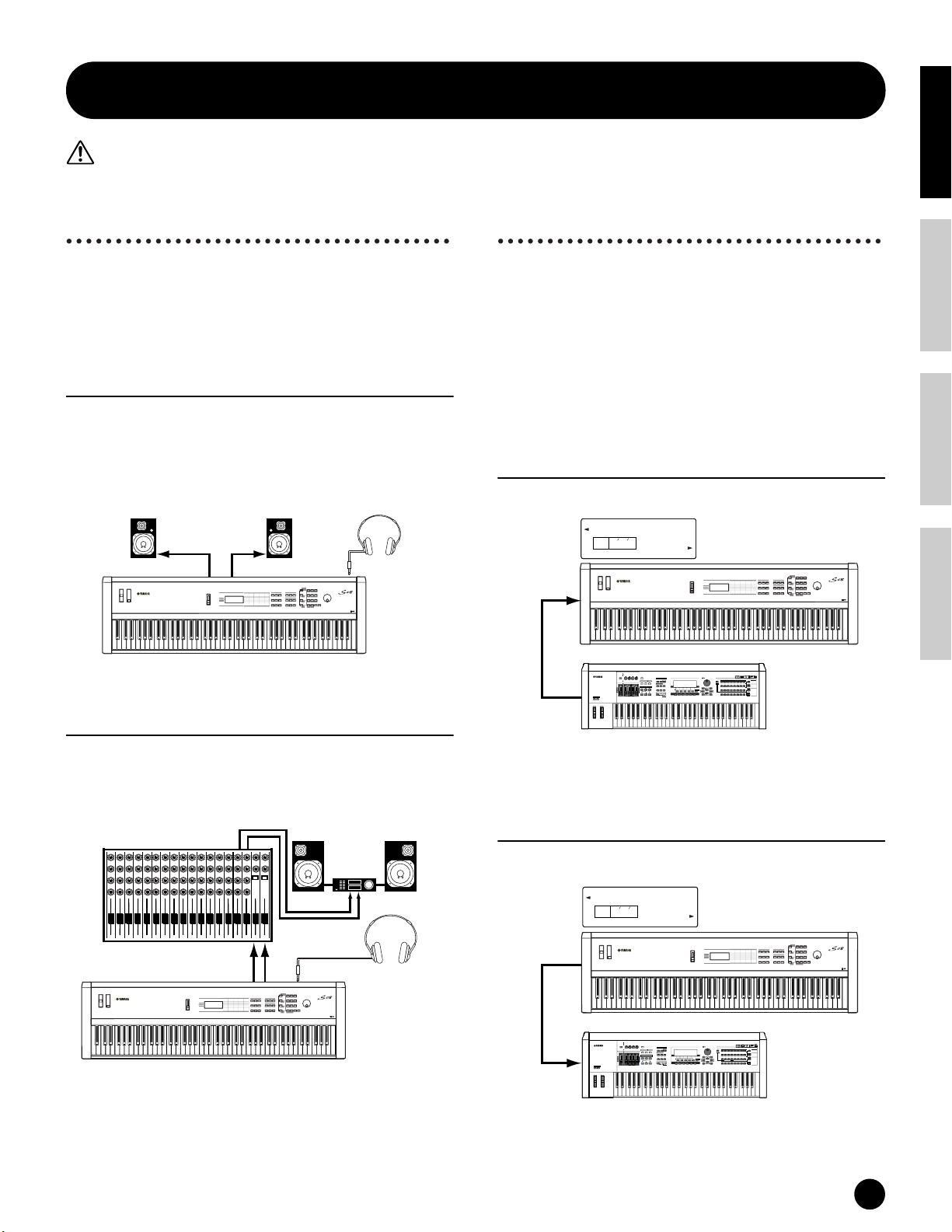
Connections
Before connecting the S08 to other electronic components, turn off the power to all the components. Before turning the power on or
off to all components, set all volume levels to minimum(0). Otherwise, electrical shock or damage to the components may occur.
Connecting to External
Connecting External MIDI
Basics SectionQuick GuideReferenceAppendix
Audio Equipment
Since the S08 has no built-in speakers, you need to
monitor its sound output via external audio
equipment. Alternatively, you could use a pair of
headphones. There are several methods of connecting
to external audio equipment, as described in the
following illustrations.
Connecting Stereo Powered Speakers
A pair of powered speakers can accurately produce the
S08’s rich sounds with their own pan and effect
settings. Connect your powered speakers to the
OUTPUT L/MONO and R jacks on the rear panel.
Powered speaker
(Left)
OUTPUT L /MONO OUTPUT R
n When using just one powered speaker, connect it to the
OUTPUT L/MONO jack on the rear panel.
Connecting to a Mixer
If you want to integrate the S08 into a larger system
with other instruments and additional audio
processing capabilities, connect it to a mixer, amplifier
and stereo monitor system as shown below.
Mixer
12345678910111213141516 L R
OUTPUT L
OUTPUT L /MONO
Powered speaker
(Right)
INPUTINPUT
R
R
L
MUSIC SYNTHESIZER
Amplifier
PHONES
MUSIC SYNTHESIZER
Stereo headphones
PHONES
S08
Speaker
Stereo
headphones
R
Equipment
You can connect an external MIDI device using a MIDI
cable (available separately) and control it from the S08.
You can also use an external MIDI keyboard or
sequencer to control the S08’s internal sounds. This
section introduces several different MIDI applications.
n The HOST SELECT (UTILITY PAGE 13) should be set
to “MIDI.” Otherwise, MIDI data will not be transmitted
from the S08’s MIDI OUT connector.
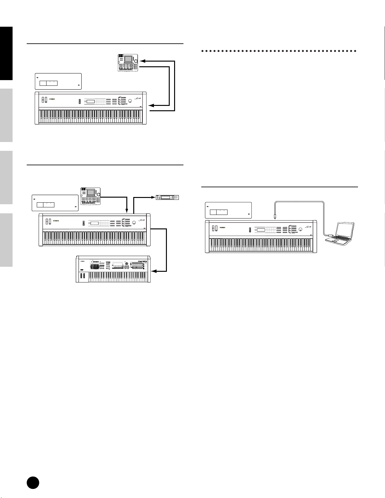
Controlling the S08 from an
External MIDI device
UTILITY PAGE 13
HostSelect
KEYELEMPART
PAGE
13
MIDI IN
OCTAVE
UP
DOWN
MIDI OUT
Controlling an External MIDI device
with the S08
UTILITY PAGE 13
HostSelect
PAGE
13
MIDI OUT
MIDI
S08
PAN
CHORUS
REVERB
TEMPO
ATTACK RELEASECUTOFF
RESONANCE
KNOB
REMOTE
ASSIGN AASSIGN B ASSIGN 1 ASSIGN 2
CONTROL
CONTROL
FUNCTION
ON/OFF
MODE
KN 1 KN 2 KN 3 KN 4
VOICEPERFORM MASTER
MEQ LOW
MEQ HI MIDMEQLOWMID MEQ HIGH
ARPEGGIO
EFFECT BYPASS
SYSTEM
ON/OFF
INSERTION
MASTER
VOLUME 1VOLUME 2 VOLUME 3VOLUME 4
VOLUME
SEQUENCER
SONG
FILE
PATTERN
SEQ
TRANSPORT
INTEGRATED
SAMPLING
UTILITY
MIXING
2
LOCATE
1
REC
EDIT
STORE
JOB
SCENE STORE
COMPARE
SET LOCATE
CS 1 CS 2 CS 3 CS 4
ZONE 1 ZONE 2 ZONE 3 ZONE 4
External MIDI keyboard
or synthesizer
KEYELEMPART
MIDI
DRUM KITS
FAVORITES
COMMON
DEC/NO INC/YES
SONG SCENE
INFORMATION
SF 1SF 2SF 3SF 4SF 5
ENTER
EXIT
F1 F2 F3 F4 F6F5
EXECUTE
MUSIC SYNTHESIZER
MUSIC
SYNTHESIZER
PRODUCTION
Sequencer
Sampling
Integrated
Real-timeExternalControl
Surface
Modular
SynthesisPlug-in
System
SLOT 1 SLOT 2 SLOT 3
CATEGORY
PRE 2
PRE 1
PRE 3
PLG 3
PLG 2
USER PLG 1
GM
SEARCH
BANK
GUITAR/
KEYBOARD
BRASS
STRINGS
A. PIANO
ORGAN
REED/PIPE
BASS
PLUCKED
D
B
E
SECTION
A
C
FGH
GROUP
DRUM/
SYN COMPCHROMATIC
SE
SYN LEADSYN PAD/
MUSICAL FXCOMBI
PERCUSSION
PERCUSSION
CHOIR
TRACK
1
34567
2
8
SELECT
ELEMENT/PERF.PART/ZONE
NUMBER
11
12
10
131416
9
15
MUTE
SOLO
MUSIC SYNTHESIZER
S08
n Connecting a pair of headphones does not affect audio
output from the OUTPUT (L/MONO and R) jacks. The
audio output at the PHONES jack and the OUTPUT
jacks is exactly the same.
MIDI IN
PAN
CHORUS
REVERB
TEMPO
ATTACK RELEASECUTOFF
RESONANCE
KNOB
REMOTE
ASSIGN AASSIGN B ASSIGN 1 ASSIGN 2
CONTROL
CONTROL
FUNCTION
ON/OFF
MODE
KN 1 KN 2 KN 3 KN 4
VOICEPERFORM MASTER
MEQ LOW
MEQ HI MIDMEQLOWMID MEQ HIGH
ARPEGGIO
EFFECT BYPASS
SYSTEM
ON/OFF
INSERTION
MASTER
VOLUME 1VOLUME 2 VOLUME 3VOLUME 4
VOLUME
SEQUENCER
SONG
FILE
PATTERN
SEQTRANSPORT
INTEGRATED
SAMPLING
UTILITY
MIXING
2
LOCATE
1
REC
EDIT
STORE
JOB
SCENE STORE
COMPARE
SET LOCATE
CS 1 CS 2 CS 3 CS 4
OCTAVE
UP
DOWN
ZONE 1 ZONE 2 ZONE 3 ZONE 4
External MIDI keyboard
or synthesizer
S08
MUSIC
SYNTHESIZER
PRODUCTION
Sequencer
Sampling
Integrated
Real-timeExternalControl
Surface
Modular
SynthesisPlug-in
System
SLOT 1 SLOT 2 SLOT 3
CATEGORY
PRE 1 PRE 2
PRE 3
PLG 3
USER PLG 1
PLG 2
DRUM KITS
GM
SEARCH
BANK
GUITAR/
KEYBOARD
BRASS
STRINGS
A. PIANO
ORGAN
REED/PIPE
FAVORITES
BASS
PLUCKED
COMMON
D
B
E
SECTION
A
C
FGH
DEC/NO INC/YES
SONG SCENE
INFORMATION
SF 1SF 2SF 3SF 4SF 5
EXIT
F1 F2 F3 F4 F6F5
GROUP
DRUM/
SYN COMPCHROMATIC
SE
SYN LEADSYN PAD/
MUSICAL FXCOMBI
PERCUSSION
PERCUSSION
CHOIR
TRACK
1
34567
2
8
SELECT
ELEMENT/PERF.PART/ZONE
NUMBER
11
12
10
131416
9
ENTER
15
MUTE
EXECUTE
SOLO
Connections
13
Basics Section Quick Guide Reference Appendix
Recording and Playback using an
External MIDI Sequencer
Connecting to a Personal
Computer
MIDI IN
UTILITY PAGE 13
HostSelect
KEYELEMPART
PAGE
13
MIDI
External
MIDI sequencer
MUSIC SYNTHESIZER
MIDI OUT
MIDI IN
MIDI OUT
S08
Controlling Another MIDI Device via
MIDI THRU
UTILITY PAGE 13
HostSelect
KEYELEMPART
PAGE
13
MIDI
External
MIDI sequencer
MIDI OUT
MIDI IN
MUSIC SYNTHESIZER
MIDI sequencer
MIDI IN
MIDI THRU
External
MIDI OUT
You can use a connected computer to control the S08
and to transfer S08 data to/from computer via MIDI.
With the included Voice Editor program, for instance,
you can edit the Voices of the S08.
There are two ways to connect your S08 to a computer:
Depending on your particular computer, the
connections may differ. (See below.)
n You may also want to change the Local On/Off setting
(pages 15 and 67), depending on how you are using the
S08 in your MIDI system.
n You will also need the appropriate MIDI application
(sequencer, editor, etc.), compatible with your computer
platform.
1: USB connection
UTILITY PAGE 13
HostSelect
KEYELEMPART
PAGE
13
USB
USB connecter
MUSIC SYNTHESIZER
USB cable
S08
PAN
CHORUS
REVERB
TEMPO
ATTACK RELEASECUTOFF
RESONANCE
KNOB
REMOTE
ASSIGN AASSIGN B ASSIGN 1 ASSIGN 2
CONTROL
CONTROL
FUNCTION
ON/OFF
MODE
KN 1 KN 2 KN 3 KN 4
VOICEPERFORM MASTER
MEQ LOW
MEQ HI MIDMEQLOWMID MEQ HIGH
ARPEGGIO
EFFECT BYPASS
SYSTEM
ON/OFF
INSERTION
MASTER
VOLUME 1VOLUME 2 VOLUME 3VOLUME 4
VOLUME
SEQUENCER
SONG
PATTERN FILE
SEQ
TRANSPORT
INTEGRATED
SAMPLING
UTILITY
MIXING
SONG SCENE
SF 1SF 2SF 3SF 4SF 5
2
LOCATE
1
REC
EDIT
STORE
JOB
F1 F2 F3 F4 F6F5
SCENE STORE
COMPARE
SET LOCATE
CS 1 CS 2 CS 3 CS 4
OCTAVE
UP
DOWN
ZONE 1 ZONE 2 ZONE 3 ZONE 4
MUSIC
SYNTHESIZER
PRODUCTION
Sequencer
Sampling
Integrated
Real-timeExternalControl
Surface
Modular
SynthesisPlug-in
System
SLOT 1 SLOT 2 SLOT 3
CATEGORY
PRE 2
PRE 1
PRE 3
PLG 3
USER PLG 1
PLG 2
DRUM KITS
GM
SEARCH
BANK
GUITAR/
KEYBOARD
BRASS
STRINGS
A. PIANO
ORGAN
REED/PIPE
FAVORITES
BASS
PLUCKED
COMMON
D
SECTION
B
E
A
C
FGH
DEC/NO INC/YES
INFORMATION
EXIT
GROUP
DRUM/
SE
SYN COMPCHROMATIC
MUSICAL FXCOMBI
SYN LEADSYN PAD/
PERCUSSION
PERCUSSION
CHOIR
TRACK
1
34567
2
8
SELECT
ELEMENT/PERF.PART/ZONE
NUMBER
11
12
10
131416
9
ENTER
MUTE
15
EXECUTE
SOLO
MIDI IN
External MIDI synthesizer
With the above MIDI connections, you can send MIDI
data from the S08’s MIDI OUT terminal, while
sending MIDI data from the external sequencer to an
external MIDI synthesizer via the S08’s MIDI THRU
terminal.
n MIDI THRU simply relays the MIDI messages received
via MIDI IN.
n The MIDI cable should be no greater than 15 meters in
length, and there should be no more than three devices in
a MIDI chain (chained in series via each unit’s MIDI
THRU). To connect more units, use a MIDI Thru Box
for parallel connections. You may encounter errors if the
MIDI cables are too long or if too many devices are
chained together via their MIDI THRU connectors.
Computer
S08
n The data via the MIDI IN terminal is ignored when using
the USB port (Host Select set to “USB”).
n When connecting the S08 to a computer with a USB
cable, make sure that the USB cable is properly connected
before turning on the power.
Be careful not to turn off the power of the S08 if an
application using the USB/MIDI connection is currently
running.
n The USB connection can only be used for transfer of
MIDI data. No audio data can be transferred via USB.
n Once connected via USB, the S08 begins communication
after a short time.
n Keep in mind that when using Windows 2000/XP, some
operating problems on the computer may occur during
startup. If this happens, try turning on the power of the
S08 only after the computer is properly running.
n When connecting the S08 and your computer via USB,
make sure to connect them directly without routing
through a USB hub.
14
Connections

2:
Echo Back On
Local Off
Computer with
Application Software
Tone
Generator
Keyboard
S08 Local Sw=on
OUT
IN
USB
MIDI connection
Using the computer’s MIDI interface
When MIDI “Echo” is disabled on the software/
computer, set the S08 Local Switch to “on.”
UTILITY PAGE 13
HostSelect
KEYELEMPART
PAGE
MIDI
13
MIDI IN MIDI OUT
MIDI cable
MUSIC SYNTHESIZER
MIDI
OUT
MIDI
NEC MultiSync
AS
PC-9821
Computer with
IN
MIDI interface
S08
Using an external MIDI interface
UTILITY PAGE 13
HostSelect
KEYELEMPART
PAGE
13
MIDI
MIDI IN MIDI OUT
S08
n Please use the appropriate MIDI interface for your
computer.
Local On/Off — When Connected to a
Computer (UTILITY PAGE 12)
When connecting the S08 to a computer, the
keyboard performance data is generally sent to the
computer, and then returned from the computer to
play the tone generator or sound source. If the Local
Switch is set to “on,” a “double” sound may result,
since the tone generator is receiving performance
data from both the keyboard directly and the
computer. Use the setting suggestions below as a
guideline; specific instructions may differ depending
on your computer and the software used.
MIDI OUT
MIDI IN
MIDI interface
MUSIC SYNTHESIZER
Serial port
(modem or printer port)
or USB port
Computer
Basics SectionQuick GuideReferenceAppendix
NEC
n Although not indicated in the illustration above,
the S08 actually receives and responds to MIDI
data from the computer application (sequencer),
regardless of the Local Sw setting on the S08.
* MIDI “Echo” is a function on sequencers that
takes any data received via the MIDI IN and
“echoes” it (or sends it as is) through the MIDI OUT.
In some software, this function is also called “MIDI
Thru.”
n Refer to the owner’s manual of your particular
software for specific instructions.
Connecting Controllers
The S08 has controller jacks on the rear panel,
including FOOT SWITCH and FOOT CONTROLLER.
You can connect optional controllers such as a
footswitch (the FC4 or FC5) and foot controller (the
FC7) to control tone, volume, pitch and other
parameters.
n Details about how to use these controllers are given on
page 37.
Rear panel
When MIDI “Echo” is enabled on the software/
computer, set the S08 Local Switch to “off.”
Computer with
USB
IN OUT
Tone
Generator
Local Off
Keyboard
S08 Local Sw=off
n When transmitting or receiving System Exclusive
data (such as with the Bulk Dump function, pages
36 and 49), use the setting example below, making
sure that MIDI “Echo” on the computer software is
set to “off.”
Application Software
OUT
IN
Echo Back On
FOOT SWITCH
FC4 or FC5
FOOT
SWITCH
FOOT
CONTROLLER
STANDBY
ON
OUTPUT
R
DC IN
FOOT CONTROLLER
FC7
Connections
L/MONO
PHONES
15

Basics Section Quick Guide Reference Appendix
Demo Playback
The S08 features a variety of demo songs, showcasing its dynamic sound and sophisticated functions.
n Make sure the synthesizer is ready for playback. Details are given in the section “Before Use” on page 12.
7
89
GUITARORGANPIANO
4
56
BASS STRINGS BRASS
3
2
1
SYN LEAD
SYN PAD
—
0
CHROMATIC
KEYBOARD
PERCUSSION
EXITENTER
Select the
category
3
VOICE
1
+
MODE
MULTI SEQ PLAY
PART/ ELEMENT/ KEY
+—
MUTE
DRUM
PRESET
CATEGORY
SEARCH
3
DEMO
UTILITY CONTROLLER CARD
JOB
EDIT
COMPARE
STORE
PLAY/STOP
COMMON
DATA
INC/YESDEC/NO
2
DRUM/PERC
USER
SE
GM2/XG
OTHER
REED/PIPE
SYN COMP
1 Press the [MULTI] and [SEQ PLAY] buttons simultaneously to call up the Demo screen and automatically start
playback of the Demo song.
Demo Song Selection
While the Demo song is playing back, you can select the particular Demo song that you wish to hear.
Enter the desired Demo song category from the numeric keypad to call up the song.
For example, you can play the piano song by pressing button 7 (PIANO) in the numeric keypad. If you don’t select a
particular song, an ensemble (OTHER) song will play back automatically.
n When there are several Demo songs contained in one category, you can select from among the available songs by using the
[DEC/NO] and [INC/YES] buttons.
2 The [PLAY/STOP] button lets you pause playback and then start again from the same point in the song.
3 To stop Demo playback, press one of the following buttons: [VOICE], [MULTI], [SEQ PLAY] or [EXIT].
This exits from the Demo mode and automatically returns to the Multi mode, Voice mode, or the mode previously
selected.
n Demo song playback continues indefinitely until stopped.
Overview of the S08
The S08 has a wide variety of advanced and convenient features. This section gives you an overview of these
features. The following diagram shows the various component sections or “blocks” of the S08.
Controller
Memory Card
File
S08
Data
Song
Load
Save
Sequencer
(Playback)
keyboard controllers
Tone Generator
Effect
Reverb
Chorus
Variation
16
Demo Playback
Demo Playback/Overview of the S08

Controller
This block consists of the keyboard, Pitch Bend and Modulation wheels and so on (page 37). The keyboard itself
doesn’t generate sounds, but instead sends note, velocity and other information to the S08’s tone generator section
for the notes you play. The controllers also send non-note performance data. Information from the keyboard and
controllers can be transmitted to other external MIDI devices through the MIDI OUT connector.
Tone Generator
This block plays back sounds according to information received from the keyboard and controllers. The following
example illustrates the path taken by the signal from an Element in the Voice Mode.
Controls the output level (amplitude) of
Controls the pitch of each Element
output from the OSC section.
Tone Generator
each Element output from the FILTER
section. The signls are then sent at this
level to the Effects Unit.
Basics SectionQuick GuideReferenceAppendix
OSC
(Oscillator)
Outputs the waveform of each Element.
Each Voice consists of up to four Elements.
FILTERPITCH
Changes the tonal quality of each
Element output from the PITCH section.
AMP
(Amplitude)
To Effects Units
About the Tone Generator (AWM2) & Waveform (Wave)
The tone generator of the S08 utilizes the sophisticated AWM2 system.
AWM2 (Advanced Wave Memory 2) is a synthesis system based on the use of sampled waveforms, and is used in
many Yamaha synthesizers. For extra realism, each AWM2 Voice uses multiple samples of a real instrument’s
waveform. Furthermore, a wide variety of envelope generator, filter, modulation, and other parameters can be
applied to the basic waveform.
n AWM2 is not just limited to conventional pitched instruments (Normal Voices), but also produces various drum and percussion
instruments (Drum Voices). For details about Normal and Drum Voices, see page 22.
Maximum Polyphony
The maximum polyphony of the S08 is 64 notes. However, the actual note polyphony will vary depending on the
number of Elements in the Voice. To calculate the actual polyphony, divide the total polyphony of 64 by the number
of Elements in the Voice. For instance, if a Voice consists of two Elements, the maximum note polyphony for the
Voice is 32.
Effects
The effects can be used to change or enhance the sound of a Multi or Voice.
These include the effects of the Reverb section (17 types) for adding ambient after-tones to the sound, the Chorus
section (17 types) that add animation and depth, and the Variation section (54 types) which features a wealth of
additional effects.
n For more details about the effects, see page 46.
Card Drive/Sequencer
The Card Drive block lets you save data or load data to/from the Memory Card (page 53).
The sequencer block can be used to play back Standard MIDI Files held on Memory Card (page 51).
Overview of the S08
17

Basics Section Quick Guide Reference Appendix
Parameter Table
The numbers in each column indicate the display PAGE corresponding to the parameter at left (with the exception of the
column on the far right, which indicates the corresponding manual page). For example, you can see that the Reverb Send
parameter is found on three separate display pages: PAGE 22 of Multi Part Edit, PAGE 11 of Normal Voice Common Edit,
and PAGE 9 of Drum Voice Key Edit.
This table is helpful in locating the corresponding display pages in different modes. This is handy when you want to make
the same or similar settings to the same parameter in a different mode — for example, setting the Reverb Send in the Multi
mode to the same value as Reverb Send in the Voice mode. It’s also handy for cross-checking same parameters for
programming complex sound changes — such as setting the Voice’s Filter Cutoff to a certain value, then going to Cutoff in
the Multi mode and tweaking it further.
Since the owner’s manual page reference is also provided, you can quickly find the corresponding explanation by checking
the currently selected mode and PAGE number on the S08, and referring to this table.
Parameter Type LCD Display (parameter name) Common Element/Key Manual
GENERAL Name 1 1 1 58, 62, 63
EFFECT* RevEF (Reverb Effect Type) 463
VOICE (Voice Selection) 164
MIX Volume (2) (3) (1) (2) 2 64
TONE VelSnsDpt/Ofs (Velocity Sensitivity Depth/Offset) 4 10 58, 64
CONTROLLER* Porta Sw/Time (Portamento Switch/Time) 5 15 58, 65
Total Vol (Total Volume) 2 2 (2) 58, 63
Total Lvl (Level) 2 3 (1) 58, 59, 62
Transpose 363
Rcv Ch (MIDI Receive Channel) 63 64, 66
NoteShift/Detune 7 7 59, 64
Mono/Poly 3 8 58, 64
Part Mode 964
OrgKt (Original Kit) 2 62
(Reverb Parameters) 563
Rev Return (Reverb Return) 663
Reverb Pan 763
ChoEF (Chorus Effect Type) 863
(Chorus Parameters) 963
Cho Return (Chorus Return) 10 63
Chorus Pan 11 63
SndCho→Rev (Send Chorus to Reverb) 13 12 58, 63
VarEF (Variation Effect Type) 14 13 58, 63
(Variation Parameters) 15 14 59, 63
VarConnect (Variation Connection) 15 63
Var Return (Variation Return) 16 63
Var Pan 17 63
Snd Var→Rev (Send Variation to Reverb) 18 64
Snd Var→Cho (Send Variation to Chorus) 19 64
MW VarCtl (MW Variation Effect Control Depth) 16 20 59, 64
AC1VarCtl (AC1 Variation Effect Control Depth) 17 21 59, 64
ReverbSend 11 9 22 58, 62, 65
ChorusSend 12 10 23 59, 62, 65
Var Send (Variation Send) 24 65
V EfBypass (Voice Effect Bypass) 14 67
Pan 42 3 59, 62, 63
NtLmt-L/H (Note Limit Low/High) 5 4 59, 64
VelLmt-L/H (Velocity Limit Low/High) 6 5 59, 64
Cutoff/Resonance 13 7 11 60, 62, 64
Attack/Decay/Release Tm (Attack/Decay/Release Time) 12 64
PEG L/Tm (PEG Level/Time) 13 65
Vib Rate/Depth/Delay (Vibrato Rate/Depth/Delay) 14 65
PB Range (Pitch Bend Range) 6 16 58, 65
MW FltCtl (MW Filter Control) 7 17 58, 65
MW PMod (MW LFO Pitch Modulation Depth) 8 18 58, 65
MW FMod (MW LFO Filter Modulation Depth) 8 18 58, 65
MW AMod (MW LFO Amplitude Modulation Depth) 8 18 58, 65
AC1 CC No (AC1 Control Number) 19 8 65, 67
AC1FltCtl (AC1 Filter Control) 9 20 58, 65
AC1 FMod (AC1 LFO Filter Modulation Depth) 10 21 58, 65
AC1 AMod (AC1 LFO Amplitude Modulation Depth) 10 21 58, 65
Voice Edit Multi Edit
Normal Drum Normal Drum
Common
Part
UTILITY
CONTROLLER
Owner's
Page
18
Parameter Table

Parameter Type LCD Display (parameter name) Common Element/Key Manual
OSC/MIX (Oscillator/Mixer) Element Sw (Element Switch) 1 59
PITCH NoteShift/Detune 7 7 59, 64
FILTER Cutoff/Resonance 13 7 11 60, 62, 64
AMP (Amplitude) AEG R (AEG Rate) 23 61
LFO (Low Frequency Oscillator) LFO Wave 32 61
TG (Tone Generator) MasterTune 166
MIDI CHANNEL Device No (Device Number) 266
MIDI FILTER Thru Port 566
SEQ SETUP Sync 10 66
MIDI SETUP Local Sw (Local Switch) 12 67
CTRL ASSIGN MWTxCtlNo (MW Transmit Control Number) 167
(CONTROLLER ASSIGN) FCTxCtlNo (Foot Controller Transmit Control Number) 267
KEYBOARD Kbd Trans (Keyboard Transpose) 467
VELOCITY Vel Curve (Velocity Curve) 567
CTRL SETUP Ctl Reset (Controller Reset) 767
(CONTROLLER SETUP) AC1 CC No (AC1 Control Number) 19 8 65, 67
(Wave Number) 2 59
Level (2) (3) 3 1 (2) (2) 59, 62
Alt.Group (Alternate Group) 3 62
Key Assign 4 62
RxNoteOff/On (Receive Note On/Off) 5 62
PchSclSns (Pitch Scaling Sensitivity) 8 59
PchSclCN (Pitch Scaling Center Note) 8 59
PEG R (PEG Rate) 9 59
PEG L (PEG Level) 10 59
PEGSclSns (PEG Scaling Sensitivity) 11 60
PEGSclCN (PEG Scaling Center Note) 11 60
PEGRtVel (PEG Rate Velocity) 12 60
PEGLvlVel (PEG Level Velocity) 12 60
PitchCors/Fine (Pitch Coarse/Fine) 6 62
CutoffVel (Cutoff Velocity Sensitivity) 14 60
ResoVel (Resonance Velocity Sensitivity) 14 60
FltSclFlag (Filter Scaling Flag) 15 60
Flt BP1~4 (Filter Scaling Break Point 1~4) 16 60
Flt Ofs1~4 (Filter Scaling Offset 1~4) 17 60
FltSclSns (Filter Scaling Sensitivity) 18 60
FltVelCrv (Filter Scaling Velocity Sensitivity) 18 60
FEG R (FEG Rate) 19 60
FEG L (FEG Level) 20 60
FEGSclSens (FEG Scaling Sensitivity) 21 60
FEGAtkVel (FEG Attack Velocity) 22 60
FEGOthVel (FEG Other Velocity) 22 60
AEG L (AEG Level) 24 61
AEGSclSens (AEG Scaling Sensitivity) 25 61
AEGLvlVel (AEG Level Velocity Sensitivity) 26 61
AEGAtkVel (AEG Attack Velocity Sensitivity) 26 61
LvlSclFlag (AEG Level Scaling Flag) 27 61
Lvl BP1~4 (Level Break Point 1~4) 28 61
Lvl Ofs1~4 (Level Offset 1~4) 29 61
LvlSclSens (Level Scaling Sensitivity) 30 61
KeyonDelay 31 61
EG Attack/Decay1/Decay2(EG Attack/Decay1/Decay2 Rate)
LFO Phase (LFO Phase Initialize) 32 61
LFO Speed 33 61
LFO PMod (LFO Pitch Modulation Depth) 34 61
LFO FMod (LFO Filter Modulation Depth) 34 61
LFO AMod (LFO Amplitude Modulation Depth) 34 61
PLFODelay (Pitch LFO Delay) 35 61
PLFO Fade (Pitch LFO Fade Time) 35 61
Rcv Ch (Voice Mode MIDI Receive Channel) (6) 3 66
Trans Ch (MIDI Transmit Channel) 466
RxPgmChng (Receive Program Change On/Off) 666
RxBankSel (Receive Bank Select On/Off) 766
TxPgmChng (Transmit Program Change On/Off) 866
TxBankSel (Transmit Bank Select On/Off) 966
Seq Ctl (Sequencer Control) 11 66
HostSelect 13 67
FSTxCtlNo (Footswitch Transmit Control Number) 367
Fixed Vel (Fixed Velocity) 667
Voice Edit Multi Edit
Normal Drum Normal Drum
Common
862
Part
UTILITY
CONTROLLER
Owner's
Page
Basics SectionQuick GuideReferenceAppendix
n For parameters in different modes having the same name, the available parameter values and settings for that parameter may
differ depending on the mode.
n For details on parameters for the Reverb, Chorus and Variation effects, refer to the separate Data List.
n For information on the SEQ PLAY, CARD and JOB PAGES, refer to the Function List (page 58).
* In the Multi mode, the Voice Common Effect/Controller settings are ignored, and the Multi settings become effective. The Variation
Effect/Controller settings of the Voice mode can be copied to the Multi mode by using the Multi Job function (page 49).
Parameter Table
19

Basics Section Quick Guide Reference Appendix
Voices & Multis
Memory Structure
A Voice is a single instrument sound, created by using the Elements and setting various parameters. In the Voice
Play mode, you can select and play any of these Voices. In the Multi Play mode, you assign a different Voice to each
part and use a sequencer to play several Voices simultaneously.
Voices are stored in the internal memory (PRESET, USER, GM2/XG).
Multis are stored in the internal memory (USER).
Voice Play Mode
Controllers
Multi Play Mode
Controllers
Sequencer
Song Playback
Tone Generator
Voice
Playing a Voice
128 Preset Voice
PRESET
PR001~128
Tone Generator
493
Normal Voice
Multi
Part
Voice
1
PR
001
GM2/XG
2
3
4
PR
PR
002
29 Drum Voice *
XG
003
001
Playing a Multi
XG
002
5
6
7
XG
003
8
US
US
001
002
32 User Multi (MLT01
US001~128
16
PR
016
~
USER
128 User Voice
MLT32)
USDR
2 User
Drum Voice
* Drum Voices XG121~128 are not of the GM2/XG set, but are original drum kits specifically programmed for the S08.
n A total of 493 (GM2/XG) and 128 (Preset) Normal Voices plus 29 Drum Voices are available as presets. You can create and store
your own original Voices; the S08 has User memory space for 128 User Normal Voices and two User Drum Voices.
20
Voices & Multis

Overview of Voice/Element/Multi
Each Voice can consist of up to four Elements. Each Element itself is a high-quality waveform or instrument sound.
Voice & Element
Each Voice can consist of up to four Elements. Elements are made from waveforms, and the quality of the Elements
is high enough that each can be used on its own as a voice. Since you can combine up to four Elements together in a
voice, highly expressive and richly textured sounds are possible. You can also split different instrument sounds
across the keyboard to be playable separately with your left and right hands — without having to specially set up a
Multi program (page 42).
Multi
A Multi consists of up to 16 Parts, each of which can play a Normal Voice or Drum Voice Part. By assigning different
Voices and MIDI channels to each part, and by using a sequencer or computer for song data playback, you can have a
complete ensemble of 16 independent instrument sounds.You can also play Multis from the keyboard. This allows
you to set up layers of different Voices, or special key splits in which your right and left hands can play separate
Voices (page 34).
One Multi
Element 1~ 4
One Voice
Up to four elements
Common Edit parameters
+
(Effect settings etc.)
Voice
Up to 16 Voices (Parts)
One Part
Part Edit parameters
+
CH1
CH16
Different Voice
for each part
Basics SectionQuick GuideReferenceAppendix
Element Edit parameters
Oscillator
Wave (AWM2)
Common Edit parameters
One Element
LFO
Low Frequency
Oscillator
PITCH
PEG FEG AEG
Pitch Envelope
Generator
FILTER AMP (Amplitude)
Filter Envelope
Generator
EG
Amplitude Envelope
Generator
See pages 43, 44, 45
Element 1
Element 2
Element 3
Element 4
+
Sequencer
Song File
Playback
(SMF Format 0)
MIDI CH 1
Computer
SMF
Format 0
SMF
Format 1
SMF Format
Conversion
Voice Edit
~
16
Playback
Recording
Song File Playback
via MIDI/USB MIDI
Included CD-ROM
Sequencer software (Windows)
Voice Editor
Card Filer
C-2 G8
Voices & Multis
21

Basics Section Quick Guide Reference Appendix
Normal Voices & Drum Voices
There are two Voice types: Normal Voices and Drum Voices. Normal Voices are mainly pitched instrument sounds
that can be played over the range of the keyboard. Drum Voices are mainly percussion/drum sounds that are
assigned to individual notes on the keyboard. The Drum Voices also include special sound effects (SFX Kit).
Normal Voice
Voice
Element 1 ~ 4
Individual drum
sounds (different
for each key)
n The sound-to-key assignments for the Kit are fixed and cannot be changed.
n You can select whether each Part uses a Normal Voice or a Drum Voice in the Part Mode PAGE (MULTI PART EDIT PAGE 9).
Drum Voice
(C#-1
~
G5)
Part Mode Setting (MULTI PART EDIT PAGE 9)
norm (Normal Voice)
With this setting, Normal Voices can be assigned to the Part.
drum (Drum Voice)
With this setting, Drum Voices can be assigned to the Part.
drumS1/2 (Drum Setup 1/2)
Used to play commercially available song data (switches automatically).
n The part set to a setting other than “norm” is called a Drum Part.
n If you’ve edited a drum kit in Drum Voice Edit mode and you wish to use that kit, set this to “drum.”
n When an XG System On message is received from an external sequencer, this is automatically set to “drumS1.” In order to use the
settings made in Drum Voice Edit, record the appropriate message in the song data (when Part Mode is set to Drum). Refer to the
MIDI Data Format section in the separate Data List.
F0 43 10 4C 08 nn 07 01 F7 (nn=Part number) (hexadecimal)
Parameters that are effective only for parts
to which normal voices are assigned:
Parameter
Transpose COMMON 3 page 63
Mono/Poly PART 8 page 64
Porta Sw PART 15-1 page 65
PortaTime PART 15-2 page 65
MULTI EDIT
PAGE
Owner’s Manual page
22
Voices & Multis

Factory Set (Restore Factory Defaults)
This lets you restore the synthesizer’s default Internal Voices (User Memory) and Multis, as well as its System and
other settings.
Once you edit any settings, the corresponding factory defaults will be overwritten and lost.
Use the procedure below to restore the factory default settings.
When you restore the factory default settings, all the current settings for the all the Multis and User Voices will be overwritten
with the factory defaults. Make sure you are not overwriting any important data. You should back up any important data to
Memory Card or to your computer beforehand.
1 Press the [JOB] button in Utility Mode (page 24). The Factory Set display appears.
MODE
MODE
EDIT
EDIT
MULTI SEQ PLAY
MULTI SEQ PLAY
DEMO
DEMO
JOB
STORE
JOB
STORE
FactorySet
FactorySet
KEYELEMPART
PAGE
KEYELEMPART
PAGE
1
1
VOICE
VOICE
UTILITY CONTROLLER CARD
UTILITY CONTROLLER CARD
Basics SectionQuick GuideReferenceAppendix
COMPARE
COMPARE
PLAY/STOP
PLAY/STOP
2 Press the [ENTER] button. A confirmation message appears.
n To cancel the job, press the [DEC/NO] button.
3 Press the [INC/YES] button to execute the Factory Set job. After the job has been completed, a “Completed!”
message appears.
4 Press the [EXIT] button to return to the Utility mode.
Factory Set (Restore Factory Defaults)
23

Basics Section Quick Guide Reference Appendix
Basic Operations
In this section, you’ll learn about the structure of the modes of the S08, its panel display indications and its
fundamental operations.
Modes
The S08 is organized into various modes, each covering a different set of operations and functions.
Voice Mode(P.58)
Voice Play mode
Voice Edit Mode
Voice JobMode
Multi Mode(P.63)
Muiti Play Mode
Muiti Edit Mode
Multi Job Mode
Utility Mode (P.66)
Edit Mode (P.58 63)
Job Mode (P.48)
MODE
MULTI SEQ PLAY
VOICE
DEMO
UTILITY CONTROLLER CARD
JOB
EDIT
COMPARE
STORE
PLAY/STOP
Sequence Play Mode (P.51)
Card Mode (P.53)
Controller Mode (P.67)
Store Mode (P.50)
Mode Table
Mode (status) PLAY
VOICE (LED lights) page 29 page 40 page 48 page 50 Play/Edit/Save the Voice
MULTI (LED lights) page 32 pages 33, 63 page 48 page 50 Play/Edit/Save the Multi
SEQ PLAY (LED lights. When playing, it
flashes.) page 51
UTILITY (Upper in LCD lights )
CARD (Both upper and lower in
LCD light)
CONTROLLER (Lower in LCD lights)
EDIT (LED lights.
When comparing, it
flashes.)
JOB (displayed)
page 52 Song playback (from memory card)
page 23 Global settings for the entire system
STORE (displayed)
Relevant function
Save/Load the S08 data (page 54)
Controller settings (page 38)
n
You need to select the Voice/Multi before entering Edit mode. All parameters can be set and stored per Voice/Multi.
Parameters are divided into two basic groups: 1) functions that are related to each Voice (or Multi), and 2) functions
that affect all Voices (or Multis). The former are set in the Voice/Multi Edit mode and latter in the Utility mode.
Utility mode settings can be saved to memory card along with the Voices and Multis.
Selecting a Mode
There are separate Play modes for Multis and Voices. To enter each of these modes, use the appropriate MODE
button ([VOICE] for Voice Play mode, [MULTI] for Multi Play mode). There are also separate Edit and Job modes for
Multis and Voices. To enter the Edit or Job mode, simply press the [EDIT] or [JOB] button while in each respective
Play mode.
Similarly, pressing the [STORE] button in the Voice or Multi mode takes you into the Store mode where you can
store Multis or Voices. In addition, the modes mentioned above, there is also a Utility mode, which is for making
global settings to the instrument, a Controller mode, which contains Controller related settings, and the Card mode,
which contains Card related settings. Finally, there is the Demo mode, which allows you to play back the Demo
songs.
To select these, press the [UTILITY] button for the Utility mode, the [CONTROLLER] button for the Controller
mode and the [CARD] button for the Card mode.
To exit to another mode, press the respective button for that mode or the [EXIT] button.
24
Basic Operations

Display Indications
Voice mode
(ex. Voice Play mode)
1
GrandPno
KEYELEMPART
PAGE
E
XG001
324
Controller mode
16
FSTxCtlNo
PAGE
3
KEYELEMPART
64
24
Mode
Voice Mode
Voice Play (page 29) Voice Category (page 50)
Voice Edit (pages 40, 58) Parameter name
Voice Job (page 48) Job Name Settings/Source Element/Key
Multi Mode
Multi Play (page 32) Multi Category (page 50)
Multi Edit (page 33, 63) Parameter name
Multi Job (page 48) Job Name Settings/Source Part Destination Part
Sequence Play Mode
Sequence Play (page 51) Chain Step Number/Settings (Song file) Parameter name/tempo
Sequence Play Job (page 52) Job Name
Other Modes
Utility (page 66) Parameter name Settings
Utility Job (page 23) Job Name
Controller (pages 37, 67) Parameter name Settings
Card (page 53) File name/settings (Song file) Function Name
Store (page 50) Store:Store mode status Destination Store (US:User, USDR:User
Multi Mode
(ex. Multi Part edit)
17
Decay Tm
PAGE
12
Card mode (ex. Load)
001StPia>>
PAGE
5
2
Voice Name
(rarely settings)
Multi Name
(rarely settings)
Sequence Play mode Utility mode
16
KEYELEMPART
PAGE
1
42
KEYELEMPART
1
+00
1
5
234
skip
KEYELEMPART
PAGE
Seq
2
MasterTune
Store mode (ex. Normal Voice)
16
KEYELEMPART
Load
5
24
1 Top line : 10 characters 2 Bottom line : 5 characters 3 (PART/ELEM/KEY)
1
Store
KEYELEMPART
PAGE
US001
2
Details
Voice Memory Type/Voice Number
PR: Preset, US: User, XG: GM (2)/XG,
GM: GM2, USDR: User Drum, BK: Bank,
BKsfx: Bank SFX, BK dr: Bank Drum, GM
dr: GM2 Drum
Settings
(rarely Parameter name)
Multi (MLT) Number Target Part for Mute (this flashes when
Settings
(rarely Parameter name)
Drum, MLT:Multi)
EC = Common Edit Status
E1 to E4 = Element Edit status
Editing Element (this flashes when Element is muted)
Part is muted)
PC = Common Edit status
P1 to P16 = Part Edit status
Editing Part (this flashes when Part is
muted)
+0000
Basics SectionQuick GuideReferenceAppendix
5
n For information on the meaning of the display messages, see page 77. For details on each parameter, see page 58.
4 Indicates PAGE number in that mode. “E” means that the current Multi/Voice has been modified but is not yet
stored (page 50).
5 Indicates the parameter type of the currently selected parameter (page 26).
6 Indicates the relevant mode (Utility or Controller). In the card mode, both indicators light.
7 Further screens are available. Use the [ ]/[ ] buttons to select the PAGEs (page 26).
Basic Operations
25

Basics Section Quick Guide Reference Appendix
VOICE
MIX
GENERAL
TONE
CONTROLLER
EFFECT
VOICE
MIX
GENERAL
TONE
CONTROLLER
EFFECT
OSC/MIX
PITCH
FILTER
AMP
LFO
EFFECT
Selecting a Screen
[ ]/[ ] buttons
You can switch between screens by using the [▲]/[▼],
[ ]/[ ], [+]/[–] and [EXIT] buttons.
[▲]/[▼] buttons
Many of the displays consist of different screens. Use
the [▲]/[▼] buttons to select the various screens.
Previous screen (PAGE)
DATA
INC/YESDEC/NO
Next screen (PAGE)
When selecting the various display pages, an arrow
appears at the right of the LCD, indicating the
parameter type in the printed list on the panel.
For example, if the display for the Total Volume
parameter in the Multi Edit mode is called up, the
arrow in the LCD indicates that this parameter belongs
to the General type.
Some of the display pages have multiple “screens.”
These are indicated by special arrow marks in the top
right of the LCD (see below). Use the [ ]/[ ]
buttons to select these pages.
When the first screen of a mulitple-page set is called up,
the arrow points to the right (→), indicating further
screens are available. When a page in the middle of the
set is called up, arrows point in both directions (← →),
indicating you can select either the next or previous
screens. When the last screen is called up, the arrow
points to the left (←), indicating no further screens are
available.
For certain parameters (such as Voice Name, etc.),
these buttons are used to move the cursor position in
the display.
Selects the
previous screen.
Decay Tm
KEYELEMPART
PAGE
12
1
+00
DATA
INC/YESDEC/NO
Selects the
next screen.
Total Vol
PAGE
2 P
In the example below, the display for the (Element)
Cutoff parameter in the Voice Edit mode is shown, and
the arrow indicates that this parameter belongs to the
Filter type.
KEYELEMPA RT
127
Cutoff
PAGE
13 E 1
KEYELEMPA RT
1338
[+]/[–] buttons
In the Multi Edit mode, these buttons are used to select
each part. To select the Common parameters, press
both buttons simultaneously. In the Voice Edit mode,
these buttons are used to select each Element. To
select the Common parameters, press both buttons
simultaneously.
PART/ ELEMENT/KEY
MUTE+–
COMMON
n For details on the parameters and page configurations of
the Multi Edit and Voice Edit modes, refer to the relevant
mode explanations in the Reference section of this
manual.
26
Basic Operations

[EXIT] button
INC/YESDEC/NO
DATA
Entering Data
Press the [EXIT] button to move up (exit) in the
hierarchical structure and return to the previous
screen.
7
89
GUITARORGANPIANO
4
56
BASS STRINGS BRASS
3
2
1
REED/PIPE
SYN LEAD
SYN PAD
–
0
SYN COMP
CHROMATIC
KEYBOARD
PERCUSSION
n Depending on the particular operation, the [EXIT]
button performs other functions as well. These
alternates functions are indicated in the appropriate
sections of the manual.
EXITENTER
Use the [INC/YES] and [DEC/NO] buttons to increment
through the values, or input the value directly by using
the numeric keypad and the [ENTER] button.
Basics SectionQuick GuideReferenceAppendix
Moving the Cursor Position
For certain parameters, such as Voice Name and
others, the [ ]/[ ] buttons are used to move the
cursor position in the display. (The selected
character flashes.) Move the cursor to the desired
position, then set the value.
DATA
INC/YESDEC/NO
[INC/YES] and [DEC/NO]
buttons
These are used to change the value of the currently
selected parameter. You can use the [INC/YES] button
to increment a parameter setting by one step, or the
[DEC/NO] button to decrement it. If you hold down
either button, the value is continuously changed. You
can also use these buttons to answer “YES” or “NO”
when a confirmation message is displayed.
n To decrease the value by 10, simultaneously hold down
the [DEC/NO] button and press the [INC/YES] button.
To increase the value by 10, simultaneously hold down
the [INC/YES] button and press the[DEC/NO] button.
Data Dial
Rotating the data dial to the right (clockwise) increases
the value, while rotating it to the left counterclockwise) decreases it.
Basic Operations
27

Basics Section Quick Guide Reference Appendix
127
1. Total Volume (absolute)
0
Volume
Volume
Offset subtracted (-10)
Actual velocity
Offset added (+10)
2. Velocity Sensitivity offset (relative)
0
-64
Offset
+64
Numeric keypad, [ENTER]
7
button
You can specify the value for the selected parameter by
using the numeric keypad, then actually set that value
by pressing the [ENTER] button. For example, to set a
value of “100,” press (in order) the numeric keypad
buttons [1], [0], and [0]. (The parameter indicator
flashes.) Finally, press the [ENTER] button to set the
value.
Enter the value with the numeric keypad or the keyboard
Parameter
Pan (Normal Voice)
Pan (Drum Voice/Multi) Rnd: Random L63 (hard left)-L01 C (Cener) R01-R63 (hard
NtLmt-L/H Lowest/highest note
PchSclCN Basic pitch
PEGSclCN Basic pitch
Flt BP1-4 Break point
Lvl BP1-4 Break point
Alt.Group off
Reverb/Chorus /Var Pan L63 (hard left) L63 (hard left)-L01 C (Cener) R01-R63 (hard
Device No all off
Rcv Ch omni
FSTxCtlNo off PCInc
Load (User voice) all Normal 1 to 128 User Drum 1/2
Sequence Play (tempo)
ENTER + keyboard
(note number input)
01718 1~63 64 65~128 96/97 98 129~130
Scale: the note position
default tempo
L63 (hard left)-L01 C (Cener) R01-R63 (hard
Specify the value.
Numeric Keypad
89
4
56
BASS STRINGS BRASS
2
1
REED/PIPE
SYN LEAD
—
0
SYN COMP
CHROMATIC
KEYBOARD
PERCUSSION
right)
right)
right)
GUITARORGANPIANO
3
SYN PAD
ENTER
Set the value.
PCDec
KEYELEMPA RT
PAGE
100
The displayed value flashes.
PLAY (START/
STOP)
Types of Parameters (Absolute and
Relative)
There are many ways to set parameters. Some
parameters require you to directly enter numerical
settings or alphabetic characters. With others, you
can choose from a number of available settings.
Furthermore, some types of parameters are
“absolute” whereas others are “relative.”
For example, the absolute parameter in the following
illustration can be set to either “mono” or “poly.”
For other absolute parameters such as Volume, the
setting can be any value between zero and 127. The
Volume setting has a linear, one-to-one relationship
with the actual volume, as shown in the graph on the
left. However, relative parameters do not follow the
same relationship. The graph on the bottom shows
the role of the Velocity Offset parameter. The value
you have set here, known as an “offset,” is added to,
or subtracted from, the actual value. With Velocity
Offset, the specified offset value is added to, or
subtracted from, the actual velocity of the notes you
play on the keyboard. Sometimes, these types of
relative parameters are set as a percentage.
28
Basic Operations
Total Vol
KEYELEMPARTPAGE
2 E
VelSnsOfs
4 E
KEYELEMPARTPAGE
127
064
Mono/Poly
KEYELEMPARTPAGE
3 E
poly

Quick Guide
Playing Voices
You can freely select and play Voices (instrument sounds) from the PRESET, USER and GM2/XG memory groups, as
explained below.
n For details about voice, see page 20. For information on the Voice List, see the separate Data List.
n The user memory can contain up to 128 Normal Voices and 2 Drum Voices (page 20).
The Voice setting is set in the Voice Edit mode. (pages 40, 58)
Basics SectionQuick GuideReferenceAppendix
STANDBY
OUTPUT
L/MONO
RDC IN ON
PHONES
PITC
H
M
ODULATION
1
Press the [VOICE] button.
FOOT
FOOT
CONTROLLER
SWITCH
MIDI
IN OUT THRU
3.3V
USB
CARD
M
E
VOLU
UTILITY
CARD
CONTROLLER
Press the [VOICE] button (the LED lights) to enter the
Voice Play mode. The following display appears.
Category/Voice name
StPiano1
KEYELEMPART
PAGE
Memory/Voice number
PR001
4
CONTROLLER
PART/
ELEMENT
COMMON
TG
OSC/MIX
VOICE
CTRL ASSIGN
SAVE
PITCH
KEYBOARD
MIX
MIDI CHANNEL
LOAD
RENAME
VELOCITY
GENERAL
FILTER
MIDI FILTER
TONE
AMP
CTRL SETUP
SEQ SETUP
DELETE
MIDI SETUP
CONTROLLER
EFFECT
FORMAT
LFO
EFFECT
EFFECT
IMPORT
Memory buttons
DRUM
PRESET
USER
1 3 3
MODE
CARDUTILITYEDIT
MULTI SEQ PLAY
VOICE
DEMO
UTILITY CONTROLLER CARD
JOB
STORE
EDIT
COMPARE
PLAY/STOP
CATEGORY
SEARCH
DRUM/PERC
PART/ELEMENT/KEY
+–
COMMON
DATA
MUTE
INC/YESDEC/NO
2
CATEGORY
DRUM
SEARCH
PRESET
DRUM/PERC
USER
SE
GM2/XG
OTHER
Preset Voice
7
89
GUITARORGANPIANO
4
56
BASS STRINGS BRASS
3
2
1
REED/PIPE
SYN LEAD
SYN PAD
–
0
SYN COMP
CHROMATIC
KEYBOARD
PERCUSSION
1~128
User Voice
1~128
MUSIC SYNTHESIZER
EXITENTER
Now, play the Voice (indicated in the display) from the
keyboard.
2 Press a MEMORY button
to select a Voice Memory.
There are three different memory sections for the
Normal Voices (page
XG. The various Voices are assigned to each memory
section as shown below. The GM2/XG Voices are
divided into several different banks.
22): PRESET, USER, and GM2/
SE
GM2/XG
OTHER
GM2/XG Voice
GM Bank
Other Bank
Playing Voices
........
29

Basics Section Quick Guide Reference Appendix
The Drum Voices (page 22) are stored in separate areas
of the User and GM2/XG memory sections.
3 Select a Voice number.
•To call up the User Drum memory (USDR1/
USDR2):
Press the [USER] button while holding down thes
[DRUM] button.
•To call up the GM2/XG Drum memory
•To call up the XG SFX Kit memory
Press the [GM2/XG] button while holding down the
[DRUM] button.
PRESET
DRUM/PERC
USER
SE
GM2/XG
OTHER
CATEGORY
SEARCH
DRUM
User Drum 1/2
GM2/XG Drum 1~29
Selecting with the [INC/YES] and
[DEC/NO] buttons
First, press the [ENTER] button to specify the Voice
Memory, then press the [INC/YES] button to
increment the Voice Number, and press [DEC/NO] to
decrement it.
DATA
INC/YESDEC/NO
Selecting with the numeric keypad
and [ENTER] button
First, specify the Voice number with the numeric
keypad, then press the [ENTER] button to actually set
it. For example, to select voice number 100, press
buttons [1], [0] and [0] in order. (The indicated
number flashes.) Finally, press the [ENTER] button to
select the Voice.
7
89
n PRESET, of course, contains the Preset Voices. The XG
Voices are assigned in order according to the GM format,
starting with Bank 1, and various GM2/XG Voices are
distributed throughout the GM2/XG memory banks.
USER is stored in internal RAM memory and contains
factory default Voices. These can be overwritten, but can
be recalled from the original factory settings at any time
if required.
GUITARORGANPIANO
4
56
BASS STRINGS BRASS
1
1
REED/PIPE
0
2
3
SYN COMP
2
SYN LEAD
–
CHROMATIC
PERCUSSION
3
SYN PAD
ENTER
4
KEYBOARD
Set the number.Specify the number.
StPiano1
KEYELEMPART
PAGE
The displayed value flashes.
PR100
n For one- or two-digit numbers, it’s not necessary to enter
all three digits (such as, “001” or “010”). For example, to
enter Voice number “3,” simply press numeric keypad
button [3], then press the [ENTER] button.
Selecting with the data dial
Rotating the data dial to the right (clockwise) increases
the voice Number, while rotating it to the left counterclockwise) decreases it.
Solo Bow
KEYELEMPART
PAGE
PR099
30
Playing Voices
OrchHarp
KEYELEMPART
PAGE
PR101

4 Now, play the keyboard
EXITENTER
KEYBOARD
—
0
1
2
3
4
56
7
89
PRESET
USER
GM2/XG
DRUM
GUITARORGANPIANO
CATEGORY
SEARCH
BASS STRINGS BRASS
REED/PIPE
SYN LEAD
SYN COMP
DRUM/PERC
SE
OTHER
CHROMATIC
PERCUSSION
SYN PAD
Select the
category
and hear the selected
Voice. Try selecting and
playing other Voices as
well.
Selecting GM2/XG Banks
The GM2/XG Voices are divided up into several
different banks. This gives you access to an even
greater number of Voices and a wider variety of
sounds.
1 Make sure that GM2/XG memory is selected,
then call up the BK (Bank Select) display by
using the [ ] button.
DATA
INC/YESDEC/NO
Using Voice Category Search
With the Voice Category Search feature, you can
quickly find Voices within a specified Voice
Category. For example, by selecting the PIANO
Voice Category, you can instantly call up for
selection all and only those Voices which fall into the
“PF” (PIANO) Voice Category.
1 Press the [CATEGORY SEARCH] button in
Voice Mode. Its LED will light and Category
Search will be enabled. The Memory buttons
and the numeric keypad are used for selecting
categories.
Basics SectionQuick GuideReferenceAppendix
GrandPno
KEYELEMPART
PAGE
BK000
2 Select the desired Bank number by using the
[INC/YES] and [DEC/NO] buttons, or by using
the data dial.
GM2/XG Bank
Normal Voice Drum Voice
Display
BK000 0 0 BKsfx 126 0
BK001 0 1 BKdr 127 0
BK101 0 101
BKsfx 64 0
GM000 121 0
GM009 121 9
MSB LSB
↓↓↓ GMdr 120 0
↓↓↓
Display
MSB LSB
The bank is now changed. Return to the GM2/
XG display by using the [ ]/[ ] buttons and
select the desired Voice number.
n For details about Bank types, refer to the separate
Data List.
n Press the [EXIT] button to disable Category Search.
n The category names are printed under each button.
To switch between the “ME” and “CO” categories,
press the [OTHER] button.
n Refer to the Category List on page 50 for more
information on Voice category types.
2 Specify the desired Category using the buttons
above. The first Voice in that Category will be
automatically selected.
n In this step, the lowest numbered Voice of the
category is selected.
n The S08 searches in the following order: PRESET,
then USER, then GM2/XG.
3 Press the [INC/YES] button to increment the
Voice number in that category and press the
[DEC/NO] button to decrement it.
n You can use the same operation as described here
in selecting Voices for Multi Part Edit (page 64).
Playing Voices
31

Basics Section Quick Guide Reference Appendix
Using Multi Mode
Playing in Multi Mode
In the Multi Play mode, you can select and play any of the Multis.
n For more details about Multis, see pages 20 and 21. For information on the Multi List, see the separate Data List.
n Up to 32 Multis can be stored in the USER (internal) memory. These Multi settings are available in Multi Edit mode (page 63).
Here, we’ll show you how to get started with Multi Play after selecting a Multi.
1 2
STANDBY
OUTPUT
L/MONO
PHONES
PITC
H
M
ODULATION
RDC IN ON
FOOT
FOOT
CONTROLLER
SWITCH
MIDI
IN OUT THRU
3.3V
USB
CARD
MODE
MULTI SEQ PLAY
VOICE
UTILITYCONTROLLER CARD
JOB
EDIT
COMPARE
PART/ELEMENT/KEY
+—
COMMON
DEMO
DATA
STORE
PLAY/STOP
CONTROLLER
M
E
VOLU
UTILITY
CARD
CONTROLLER
PART/
COMMON
VOICE
MIX
GENERAL
TONE
CONTROLLER
EFFECT
CARDUTILITYEDIT
ELEMENT
TG
OSC/MIX
CTRL ASSIGN
SAVE
PITCH
KEYBOARD
MIDI CHANNEL
LOAD
RENAME
VELOCITY
FILTER
MIDI FILTER
AMP
CTRL SETUP
SEQ SETUP
DELETE
MIDI SETUP
FORMAT
LFO
EFFECT
EFFECT
IMPORT
7
89
CATEGORY
DRUM
SEARCH
PRESET
4
MUTE
INC/YESDEC/NO
56
DRUM/PERC
BASS STRINGS BRASS
USER
2
1
REED/PIPE
SYN LEAD
SE
—
GM2/XG
0
OTHER
SYN COMP
CHROMATIC
PERCUSSION
MUSIC SYNTHESIZER
GUITARORGANPIANO
3
SYN PAD
EXITENTER
KEYBOARD
1 Press the [MULTI] button
The [MULTI] button LED will light, showing that you
are now in the Multi Play mode. The following
appears in the display.
MODE
MULTI SEQ PLAY
VOICE
DEMO
Target Part for Mute
At this point, you can play the Multi (named on the
screen) via keyboard.
Up to 32 Multis can be stored in the USER (internal)
memory.
PRESET
USER
GM2/XG
CATEGORY
SEARCH
DRUM/PERC
SE
OTHER
DRUM
n USER is stored in internal Random Access Memory
(RAM) and contains the factory default Multis. These
can be overwritten but can recalled at any time (page 23).
Category/Multi name
MIDIGrnd
KEYELEMPAR TPAG E
P
MLT01
Multi Number
USER
~
32
1
3
2 Select a Multi Number
Press the [INC/YES] button to increment the Multi
Number. Press the [DEC/NO] button to decrement the
Multi Number.
DATA
INC/YESDEC/NO
n This is selected in the same way as in selecting Voices,
using the numeric keypad and the [ENTER] button.
Refer to the instructions on selecting Voice numbers
(page 30).
3 You can now play Parts
in the Multi via the
keyboard.
If the MIDI receive channel parameter is the same for
any Parts, those Parts can be played in unison. Now
try selecting other Multis.
n To play a Voice from the keyboard, make sure that the
MIDI Receive Channel for that Voice’s Part and the MIDI
Transmit Channel for the keyboard are both set to the
same value.
32
Using Multi Mode

Using the S08 as a
KEYELEMPART
PAGE
1 P 2
GrandPno
XG001
KEYELEMPART
PAGE
2 P 2
Volume
001
KEYELEMPART
PAGE
6 P 2
Rcv Ch
02
2 If the Common Edit display is shown, press the [+]
or [–] button to switch to the Part Edit display.
Multitimbral Tone
Generator (Multi Edit)
Multi mode lets you configure the S08 as a multitimbral
tone generator for use with computer-based music
software or external sequencers. If each track in a song
file uses a different MIDI channel, then the Parts in a
Multi can be each assigned to those MIDI channels
correspondingly. Therefore, you can play back a song
file on an external sequencer and have different Voices
playing on different tracks simultaneously.
In the following example, we will create a Multi suited
to playing back a song file consisting of three Parts:
piano, bass and drums. The piano track is assigned to
MIDI channel 2, the bass track to channel 3, and the
drums to channel 10.
n The particular part(s) can be switched on/off
temporarily (Mute).
n You can hear the difference between the newly edited
Multi and the same Multi prior to editing (page 41).
n For details about MIDI channels, see page 72.
n You can use the included sequencer software (Windows
only; see the attached Installation Guide) to play multiple
Parts on the S08. Before doing that, however, make sure
that all connections between the computer and the S08
have been properly made (page 14).
PART/ ELEMENT/ KEY
COMMON
MUTE+—
Total Vol
Volume
KEYELEMPART
PAGE
2 P
Common indicator
PAGE
2 P
127
KEYELEMPART
100
Part indicator
3 Use the [+] and [–] buttons to select Parts. Here,
you can select P2 (Part 2) for the piano, P3 (Part 3)
for bass and P10 (Part 10) for drums. First, let’s
select P2 (Part 2).
PART/ ELEMENT/ KEY
COMMON
MUTE+–
4 Use the [▲] and [▼] buttons to switch to the Voice
Selection screen (PAGE 1), then specify the Voice to
be used as the piano Part.
Basics SectionQuick GuideReferenceAppendix
Song File Multi
Part 2
Track 1
Track 2
Track 3
(sequencer software)
Piano
Bass
Drums
Computer
Transmit Ch.2
Transmit Ch.3
Transmit Ch.10
Part 3
Part 10
Piano Voice
Bass Voice
Drum Voice
Receive Ch.2
Receive Ch.3
Receive Ch.10
Tone
generator
S08
1 After pressing the [MULTI] button, press the
[EDIT] button (the respective LEDs will light). You
are now in the Multi Edit mode.
MODE
MULTI SEQ PLAY
VOICE
DEMO
UTILITY CONTROLLER CARD
JOB
EDIT
COMPARE
n Before entering the Multi Edit mode, you need to select a
Multi for editing.
n You can initialize the Multi, if necessary (page 48).
STORE
PLAY/STOP
5 Next, use the [▲] and [▼] buttons to switch to the
Volume screen (PAGE 2), then set the volume for
the piano Part as well as its Pan position, Chorus
and Reverb Send levels, if necessary. For details, see
page 65.
6 Continue using the [▲] and [▼] buttons and switch
to the Rcv Ch (MIDI Receive Channel) screen
(PAGE 6). Set the parameter to 2.
Using Multi Mode
33

Basics Section Quick Guide Reference Appendix
7 Use the [▲] and [▼] buttons and switch to the
Mono/Poly screen (PAGE 8). Set the parameter to
“poly” (polyphonic).
Performing Live While
Playing Back a Song File
Mono/Poly
n For Parts that do not require polyphony, the Mode
parameter can be set to “mono” (monophonic).
PAGE
8 P 2
KEYELEMPART
poly
8 Use the [▲] and [▼] buttons and switch to the Part
Mode screen (PAGE 9). Set the parameter to
“norm” (normal).
Part Mode
n In the case of a Drum Part, set the mode to “drum.”
n For details about the Part mode, see page 22.
PAGE
9 P 2
KEYELEMPART
norm
9 Use the [▲] and [▼] buttons to call up the NtLmt
(Note Limit) and VelLmt (Velocity Limit) settings,
and check whether or not the Part of the piano
Voice is set appropriately — in other words, make
sure that the Note or Velocity settings do not
prevent the Voice from being played normally.
Except in special cases, you should generally avoid
setting limits on the note and velocity ranges, in
order to ensure that notes are sounded properly and
are not cut off.
NtLmt-L
PAGE
4 P 2
KEYELEMPART
C-2
By following steps 3 to 9 above, when you play
back a song file in the sequencer, the piano track is
transmitted through MIDI channel 2. The MIDI
data is received by the S08 which then plays the
Voice for the Part assigned to MIDI channel 2.
While playing back the song file with the piano, bass
and drum Parts assigned earlier, you can set up the
Multi so that you can also play another Part live.
Multi
Part 1
Song File
Track 1
Track 2
Track 3
Piano
Bass
Drums
Transmit Ch.2
Transmit Ch.3
Transmit Ch.10
Part 2
Part 3
Part 10
Solo-type Voice
Piano Voice
Bass Voice
Drums Voice
Receive Ch.1
Receive Ch.2
Receive Ch.3
Receive Ch.10
Playback using
keyboard
This is the same as the Multi created earlier (page 33),
but with the addition of another Part for live playback.
Be careful to make the following important settings.
• In the Multi created earlier, Parts 2, 3 and 10 were
being used. As an example, we will now assign
another Part (Part 1) to a solo-type Voice and set the
MIDI Receive Channel to 1.
•At the Trans Ch (PAGE 4) screen in MIDI Mode,
set the MIDI Receive Channel to 1.
The Voice for Part 1 can now be played live using
the keyboard.
n Because the S08 features a fully-compatible XG tone
generator, you can play any of the wide variety of
commercially available XG/GM/GM2 song software.
This ensures broad dynamic and expressive range, with a
wide variety of rich instrument sounds and effects. You
can also mute specific parts of the MIDI data — allowing
you to practice the missing parts yourself, or to use the
song data as instrumental backing for your own singing
and playing.
Splitting the Keyboard —
Setting Upper and Lower
) Repeat steps 3 to 9 above, but set up Part 3 for
bass and to receive on MIDI channel 3.
! Repeat steps 3 to 9 again, setting up Part 10 for
drums and to receive on MIDI channel 10.
n To avoid situations where the Voices of unused Parts
are suddenly played back, you should set the MIDI
receive channels for unused Parts to “off.”
n There are many other Part-specific parameters in the
Multi Edit mode. For details, see page 63.
@ Before exiting Multi Edit Mode, you need to store
the settings for the Multi. For details about storing
Multis, see page 50.
Now, when you select this Multi in the Multi Play
mode, you can play back the song file on computer
(sequencer), and the piano, bass and drum Parts will be
played back according to each track’s MIDI channel.
34
Using Multi Mode
Ranges for the Voices
The illustration below shows an example in which the
keyboard has been effectively divided into two separate
key ranges, letting you play one Voice over one range,
and a second Voice over the other. In the following
example, the Voices change at the note C3, letting you
play a string Voice in the lower range and a piano Voice
in the upper. To set up the Voices in this way, follow
the instructions below.
n For information on setting up a key split in the Voice
mode, see page 42.

Part 1
Strings
Ch1
(C3)
UpperLower
Part 2
Piano
Ch1
1 Press the [MULTI] button, followed by the [EDIT]
button (each LED will light) to enter the Multi Edit
mode.
n You need to select the Multi before entering the Multi
Edit mode (page 32).
2 If the Common Edit screen is shown, press the [+]
or [–] button to select the Part Edit dispaly.
3 Select a Part for the lower range by using the PART
[+] and [–] buttons. For this example, select “P1
(Part 1).”
4 Use the [▲] and [▼] buttons (if necessary) and call
up the Voice Selection screen (PAGE 1) to select a
strings Voice for the lower range Part.
Strings1
n For details about Voice selection, see page 70.
KEYELEMPART
PAGE
XG049
5 Use the [▲] and [▼] buttons to call up the Volume
screen (PAGE 2), then set the volume for the piano
Part as well as its Pan position, Chorus and Reverb
Send levels, if necessary. For details, see page 62.
9 Use the [▲] and [▼] buttons to call up the Part
Mode screen (PAGE 9). Set the parameter to
“norm” (normal)
With settings made in steps 3 to 9 above, you can
now play the strings voice assigned to “P1” (Part 1)
and set to MIDI Receive Channel 1 (RcvCh) — when
you play in the key range of B2 and lower.
) Make the settings for the upper Part (Part 2), in the
same manner as you did in steps 3 to 9.
For Part 2, select a piano Voice, setting the Note
Limit Low to “C3” and the Note Limit High to the
maximum of “G8.” Also set the MIDI Receive
Channel to 1, as you did with Part 1. The piano
Voice of Part 2 sounds when you play keys higher
than C3.
n
In the Edit mode, the selected Part’s Voice is played back.
n
To avoid situations where the Voices of unused Parts
are suddenly played back, you should set the MIDI
receive channels for unused Parts to “off.”
n
There are many other Part-specific parameters in the
Multi Edit mode. For details, see page 64.
! Before exiting the Multi Edit mode, store the above
settings to a Multi. For instructions on storing a
Multi, refer to page 50.
Now that you’ve created and stored the Multi, you can
call it up anytime within the Multi play mode — and
play a strings Voice from keys B2 and below, while
playing a piano Voice from keys C3 and above.
Layering Two Voices
Basics SectionQuick GuideReferenceAppendix
6 Use the [▲] and [▼] buttons to call up the NtLmt
screen (PAGE 4), and specify a key range for the
lower and upper Parts. Switch between the NtLmtL (Note Limit Low) and NtLmt-H (Note Limit
High) screens by pressing the [ ] and [ ]
buttons. Select “C-2” for the lowest note and “B2”
for the highest.
NtLmt-L
PAGE
4 P
KEYELEMPART
C-2
NtLmt-H
PAGE
4 P
KEYELEMPART
B2
7 Use the [▲] and [▼] buttons to call up the Rcv Ch
(MIDI Receive Channel) screen (PAGE 6). Select
“1” for “RcvCh.”
n Set the MIDI Transmit Channel to 1 from the Trans
Ch display (PAGE 4 ) in the MIDI mode. Now you
are ready to play the Part 1 Voice within the lower
range. The Voice assigned to Part 1 can be played
over MIDI Receive Channel 1.
8 Use the [▲] and [▼] buttons to call up the Mono/
Poly screen (PAGE 8). Set the parameter to “poly”
(polyphonic).
(Parts) Together
The illustration below gives one application example of
combining two Voices in a layer. In this example, a strings
Voice is selected for Part 1 and a piano Voice is selected for
Part 2, and the two are played together in unison.
Part 1
Part 2
Strings Piano
This Multi can be easily created and set so that both
Parts 1 and 2 are layered together across the entire
range of the keyboard.
•For both Part 1 and Part 2, set the Note Limit Low
parameter to “C-2” and the Note Limit High
parameter to “G8.”
n In the Edit mode, the selected Part’s Voice is played
back.
Using Multi Mode
35

Basics Section Quick Guide Reference Appendix
Saving S08 Settings to an External Device
(Bulk Dump Send)
Using the Bulk Dump function, you can transmit
your S08 settings to an external device, such as a
computer, and save them. This is a fast and
convenient way to back up your important data.
You can also use this function to record important
S08 data at the beginning of a song, so that all your
original settings and data are automatically reset
when your play back the song.
The following explanation shows you how to do this
using the realtime recording functions of the
included sequence software (Windows only). In this
example, one of the MIDI track is used for recording
the User Multi data.
n Naturally, this operation is not limited to use with
the included sequence software; other sequencers
will work for this just as well. For specific
information and operation instructions, refer to
the owner’s manual (or help messages) of your
particular sequencer.
n The actual sequence software operations described
here may differ slightly depending on the version
of the software you are using and your particular
computer.
n Make sure that the S08 is properly connected to the
computer (page 14). For information on settings
for the included sequence software, refer to the online manual included with the software.
5 After starting recording on the sequence
software, press the S08’s [INC/YES] button to
transmit the data.
DATA
INC/YESDEC/NO
Bulk transmit start
Press the Play button to
activate recording
6 When data transmission is finished, stop
recording on the sequence software. Check the
List Window to confirm that the data (shown in
hexadecimal) has been properly received and
recorded by the sequence software.
n For information about recording or saving, refer to
the on-line manual included with the sequence
software.
Now, whenever you play back the song file with this
recorded data, the appropriate S08 Multi settings are
sent as System Exclusive messages (page 76) from
the sequence software.
1 In the Multi mode, select the S08 Multi you want
to transmit.
2 Press [JOB] to enter the Multi Job mode.
3 From the “BlkDmp” parameter (PAGE 5) in the
Multi Job mode, select the data type for
transmitting. Here, select “Curnt” (Current) by
using the [INC/DEC] button to transmit the
currently selected Multi data, then press the
[ENTER] button.
BlkDmp
PAGE
5
KEYELEMPART
Sure?
4 In your particular sequence software, specify a
MIDI track for recording.
Select the track for recording
Press the Record button to
activate recording standby
n For best results, try to keep the playback tempo at
the same setting as was used for recording.
n When you assign the User Voice to the selected
Multi’s Part, record the User Voice as the same
manner. Select the AllUS (All User Voices) in the
BlkDmp screen (PAGE 3) in the Voice Job mode,
then transmit the bulk data using the same method
as Multi.
n If necessary, S08 system (Utility and MIDI) data
can also be recorded. In the BlkDmp screen of the
Multi Job or Voice Job mode, select “Systm.”
n To save the S08 settings, transmit the three data
types below, and record/save them to the computer.
• All: All Multis (Multi Job mode)
• AllUs: All User Voices (Voice Job mode)
• Systm: System (Multi Job or Voice Job mode)
36
Using Multi Mode

Using Controllers
The S08 is equipped with Pitch Bend and Modulation Wheels. By connecting an optional Foot Controller or
Footswitch, you can also control a variety of parameters (such as changing the sound, changing Program Numbers,
etc.) with your feet— and leave your hands free to play the keyboard.
Basics SectionQuick GuideReferenceAppendix
Pitch Bend Wheel &
Modulation Wheel
Pitch Bend wheel’s function is to control pitch. Move the
wheel upward/downward to bend the pitch upward/
downward. The effect can also be reversed.
The more you move modulation wheel upwards, the greater
the modulation that is applied to the sound.
Pitch
up
Deeper
Pitch
down
PITC
H
M
(Pitch Bend Wheel) (Modulation Wheel)
n The Pitch Bend Range can be set for each Voice/Part
(pages 58 and 65).
n The Modulation Depth can also be set. Also, the wheel
can be assigned to control different parameters, such as
Volume or Pan (page 67).
n The Modulation Wheel can also be set to control the
tone, amplitude (volume), pitch, or filter setting of the
Voice. The Modulation Wheel can be used to control the
parameters below.
•MW Variation Effect Control Depth (VarCtl)
•MW Filter Control (FltCtl)
•MW LFO Pitch Modulation Depth (PMod)
•MW LFO Filter Modulation Depth (FMod)
•MW LFO Amplitude Modulation Depth (AMod)
MW/AC1/
NORMAL
VOICE
MULTI MW
LFO Control Depth Edit PAGE number
PMod FMod FltCtl AMod VarCtl
MW
ELEMENT 8 ELEMENT 8 ELEMENT 7 ELEMENT 8 COMMON 16
AC1
LFO
ELEMENT 34 ELEMENT 34
PART 18 PART 18 PART 17 PART 18 COMMON 20
AC1
ELEMENT 10 ELEMENT 9 ELEMENT 10 COMMON 17
PART 21 PART 20 PART 21 COMMON 21
ODULATION
ELEMENT 34
Controllers and External MIDI Control
Various control functions can be assigned to the
Modulation Wheel and the Assignable Controller
(See below). Besides these other functions, the
controllers are already set to control the tone,
volume, pitch, and filter settings. When the
controller is used, it not only affects the built-in tone
generator of the S08, but also simultaneously
outputs corresponding MIDI data via the MIDI OUT
terminal.
MIDI OUT
MIDI IN
MIDI Control
Modulation Wheel
Assignable Controller 1
Voice Control
Volume
Tone
Tone generator
Pitch ....
n When the Multi mode is active, this controls the
Part for which the Transmit Channel setting of the
MIDI mode (PAGE 4) and the Receive Channel
setting of Multi Part Edit (PAGE 6) are the same.
AC1 (Assignable Controller 1)
The AC1 (Assignable Controller 1) is available by
using an external MIDI controller (such as a foot
controller connected to a MIDI keyboard). By
setting the AC1 Control number here to match the
controller on the connected MIDI device, you can
use that controller to change the sound, according to
the settings made in the other AC1 parameters —
such as AC1FltCtl, AC1 FMod/PMod, or the
Variation Effect’s AC1VarCtl.
For example, by setting AC1 to “2” here, you can use
a breath controller to control the Voice of a Part.
The numbers in each column indicate the edit
display PAGE corresponding to the MW/AC1/LFO
control depth parameter at left.
If vibrato is also applied and you want to control
only the cutoff frequency by the Modulation wheel,
set the PMod parameter (assigned to the same
controller or LFO) to “0.”
n You can copy the controller settings of the Voice
mode to the Multi mode.
For best results, also make sure that the sensitivity
parameters (AC1FitCl, AC1 FMod/PMod, or the
Variation Effect’s AC1VarCtl) are set appropriately,
as needed.
Using Controllers
37

Basics Section Quick Guide Reference Appendix
Foot Controller
An optional Foot Controller (such as the FC7), connected
to the FOOT CONTROLLER jack (page 15) on the rear
panel, can be assigned to any one of a number of
controller parameters (page 39). By using a foot
controller for parameter control, both your hands are left
free to play the keyboard (or to operate other controllers).
This is very convenient when performing live.
n By setting the AC1 to the same control number as the
Foot Controller, you can use the Foot Controller to
continuously control the parameters below for each Part
or Voice.
• AC1 Filter Control
• AC1 LFO Filter Modulation Depth
• AC1 LFO Amplitude Modulation Depth
• AC1 Variation Effect Control Depth
The control number for AC1 can be set in the following
pages:
Multi Part Edit PAGE 19 (when controlling in the Multi
mode)
Controller PAGE 8 (when controlling in the Voice mode)
See next section below for information on setting the
control number for the Foot Controller.
Using the Foot Controller to Control
Parameters
In live performance, you can use the Foot Controller
onstage to keep your hands free to play the
keyboard, yet still be able to control various
functions necessary for your songs or performance.
In the following example, we’ll show you how to set
up the Foot Controller to function the same as (and
substitute for) the Modulation Wheel.
3 Use the [INC/DEC] buttons to select “01”
(Modulation Wheel).
DATA
INC/YESDEC/NO
FCTxCtlNo
KEYELEMPART
PAGE
2
01
The Foot Controller can now be used to perform the
same control function as that of the Modulation
Wheel.
n For details about Control Numbers and Control
Change messages, refer to the separate Data List.
Foot Switch
An optional Yamaha FC4 or FC5 Foot Switch
connected to the rear panel FOOT SWITCH jack (page
15
) can be assigned to a range of parameters. This is
designed for switch-type (on/off) controls such as
incrementing/decrementing Voice or Multi numbers,
and cannot be used for continuous control of a
parameter. The default factory setting for this is to
control sustain (FSTxCtlNo = 64).
n See next section below for information on setting the
control number for the Foot Switch. For details about
Control Numbers and Control Change messages, refer to
page 73 and the separate Data List.
1 Press the [CONTROLLER] button to enter the
Controller mode.
MODE
MULTI SEQ PLAY
VOICE
DEMO
UTILITY CONTROLLER CARD
JOB
EDIT
COMPARE
2 Press the [
STORE
PLAY/STOP
▲] and [▼] buttons to call up the
MWTxCtlNo
PAGE
1
KEYELEMPART
01
FCTxCtlNo (FC transmit Control Number)
screen (PAGE 2).
DATA
INC/YESDEC/NO
Using the Foot Switch to Advance Through Programs
When performing live, you can set up the Foot Switch
to change Voices or Multis with your feet, without
having to take your hands from the keyboard. For
example, if you arrange the Voices/Multis in memory
in consecutive order (as you’ll use them), you can
easily advance through them one-by-one by pressing
the Foot Switch while you perform. The following
instruction steps show you how to do this.
1 Press the [CONTROLLER] button to enter the
Controller mode.
MODE
MULTI SEQ PLAY
VOICE
DEMO
UTILITY CONTROLLER CARD
JOB
EDIT
COMPARE
STORE
PLAY/STOP
MWTxCtlNo
PAGE
1
KEYELEMPART
01
38
Using Controllers

2 Use the [▲] and [▼] buttons to call up the
FSTxCtrlNo (FS transmit Control Number)
screen (PAGE 3).
DATA
INC/YESDEC/NO
FSTxCtlNo
KEYELEMPART
PAGE
3
64
3 Press the [INC/DEC] buttons to select “96”
(PCInc). (Or, input the number 96 and press
the [ENTER] button.)
DATA
INC/YESDEC/NO
FSTxCtlNo
KEYELEMPART
PAGE
3
PCInc
In the Voice/Multi mode, the Foot Switch can now
be used to advance through program numbers.
Primary control number and function
MW/AC1/FC (Variable control) FS (on/off switch)
7 Volume 64 Hold 1 (Sustain)
10 Pan 65 Portamento Switch
11 Expression 66 Sostenuto
71 Harmonic Contents (Resonance) 67 Soft Pedal
72 Release Time 96 Program Change INC
73 Attack Time 97 Program Change DEC
74 Brightness 98 PLAY/STOP
75 Decay Time
76 Vibrato Rate
77 Vibrato Depth
78 Vibrato Delay
91 Reverb Send Level
93 Chorus Send Level
94 Variation Effect Send Level
Basics SectionQuick GuideReferenceAppendix
See page 73
Controlling the Rate/Level of the Pitch, Filter, AMP, EG without Controllers (Normal Voice Element Edit PAGE number)
You can control the various parameters according to the note position or velocity (how strongly you play the keys).
The table is helpful in locating the corresponding display pages in different parameters. For example, if you want to
control the filter cutoff frequency and AEG level by velocity, you can set the relevant parameters in PAGE 14-1/26-1.
Target parameters
PITCH (P) FILTER (F) AMP (A)
Control parameters
Velocity Sensitivity
Scaling Sensitivity 8-1 11-1
Scaling (BP/Ofs)
EG rate/EG level 9/10 19/20 23/24
PITCH PEG FILTER FEG AMP AEG
Rate Level Cutoff Resonance Rate Attack
12-1 12-2 14-1 14-2 22-1 22-2 (MULTI PART 10)
18-1 21 25 30
15/16/17 27/28/29
Rate
Other
Rate
(VOICE COMMON 4)
(CONTROLLER 5)
Rate Attack
Rate
26-2 26-1
Level
Using Controllers
39

Basics Section Quick Guide Reference Appendix
DEMO
VOICE
MULTI SEQ PLAY
MODE
DEMO
UTILITY CONTROLLER CARD
EDIT
JOB
STORE
COMPARE
VOICE
MULTI SEQ PLAY
MODE
PLAY/STOP
Voice Edit
The following procedure shows you the fundamentals in creating and editing Voices.
Of course, this is just one example; you are free to set any parameters in any way you like. Details about each
parameter are given in the Reference section of this manual (page 58).
n All parameter settings are stored along with the Voice itself.
1 Selecting a Voice to Edit
1
In Voice Play mode, select the Voice you wish to edit.
2
Enter the Voice Edit mode.
3
Set the common parameters
● Set the parameters common to all Elements in the
Voice (volume, pitch, tone, etc.) You can also set
parameters related to the Controllers, Effects, and
so on.
4
Set the element parameters
● From the OSC/MIX (Oscillator/Mix) screens, select
the Waves used by the Elements in the Voice, plus
the volume, pan, note range and other basic
parameters.
● From the PITCH screens, set the tuning and other
pitch-related parameters used by the Elements.
Also set the PEG (Pitch Envelope Generator)
parameters as necessary.
● From the FILTER screens, adjust the parameters
of the filters used by the Elements. Also set the
FEG (Filter Envelope Generator) parameters as
necessary.
● From the AMP (Amplitude) screens, set the
volume and other output level-related parameters
used by the Elements. Also set the AEG
(Amplitude Envelope Generator) parameters as
necessary.
● From the LFO (Low Frequency Oscillator) screens,
set the modulation-related parameters used by the
Elements.
Enter the Voice Play mode by pressing a [VOICE]
button.
Select the Voice Number of the Voice you wish to edit
(page 29).
n When you’re creating a Voice by editing an existing one,
it helps to select a Voice with a sound that’s relatively
similar to the one you intend to create. In this way, you
can avoid having to make large changes and many
parameter edits — allowing you to create a Voice quickly
and easily. If you are creating a Voice from scratch, use
the convenient Initialize function (in the Voice Job
mode) to initialize a Voice in internal user memory. For
details, see page 48.
2 Entering the Voice Edit
Mode
All Voice creation and editing is carried out in Voice
Edit Mode.
To enter the Voice Edit mode, press the [EDIT] button
while in the Voice Play mode.
5
Set the effect parameters.
6
Store the edited Voice.
40
Voice Edit

Common Edit and Editing Individual
Elements
Voices can consist of up to four Elements (page 21). Use
Common Edit to edit the settings common to all four
Elements. The Voice Edit mode can be divided into screens
for Common Edit and those for editing each Element. In
the Voice Edit mode, simultaneously press both the [–] and
[+] buttons to switch between the Common Edit screens
and the screens for editing each Element.
Common Edit screens
GrandPno
KEYELEMPART
PAGE
1 E
Common indicator
Name
n The compare function is also available in the Multi
Edit mode.
n The Multi parameters that cannot be set from the
panel will be initialized when using the compare
function in the Multi Edit mode.
Basics SectionQuick GuideReferenceAppendix
Switching Between Screens and Entering
Settings
After selecting a Common Edit screen or an edit
screen for an Element (1 to 4), press the [▲] and [▼]
buttons to switch to other screens.
DATA
INC/YESDEC/NO
Element Edit screens
PART/ ELEMENT/ KEY
COMMON
MUTE+—
Element Sw
KEYELEMPART
PAGE
1 E 1
Element indicator
on
n In the same manner as in the Voice edit mode, you
can also switch between the Common Edit screens
and the Part Edit screens in the Multi Edit mode.
Switching Elements (or Keys, Parts)
On/Off (Mute)
In Edit Mode, an Element can be switched on/off
temporarily when you press the [MUTE] button.
The Element indicator which is muted will flash.
This lets you mute other Elements in the Voice so
that you can listen to the changes to the Element
that you are editing.
PART/ ELEMENT/ KEY
COMMON
n In the Multi mode (including the Play mode), in
the same manner as in the Voice Edit mode, Parts
can be switched on/off temporarily.
MUTE+—
KEYELEMPART
PAGE
1 E
Page
The S08 has a huge variety of available parameters.
As you change the display pages, an arrow mark on
the right side of the display points to the parameter
chart printed on the panel, indicating the parameter
type and what aspect of the instrument it’s related
to.
Level
PAGE
3 E
KEYELEMPAR T
100
VOICE
MIX
GENERAL
TONE
CONTROLLER
EFFECT
OSC MIX
PITCH
FILTER
AMP
LFO
EFFECT
Use the [INC/YES] and [DEC/NO] buttons to set
each parameter value.
DATA
INC/YESDEC/NO
Level
PAGE
3 E
KEYELEMPART
101
The Compare Function
Use this to listen to the difference between the
Voice/Multi with your edited settings and the same
Voice/Multi prior to editing.
1 Press the [COMPARE (EDIT)] button while in
Edit mode. The EDIT LED will flash and the
settings prior to editing will temporarily be
reinstated for comparison purposes.
n
While the Compare function is enabled, the [DEC/NO]
and [INC/YES] buttons cannot be used for editing.
2 Press the [EDIT] button again to disable the
Compare function and restore your recently
edited settings.
Some parameters have multiple “pages,” indicated
by a special arrow mark (“→”) in the top right of the
LCD (see below). Use the [ ]/[ ] buttons to
select these pages.
DATA
INC/YESDEC/NO
NtLmt-L
NtLmt-H
PAGE
5 E 1
PAGE
5 E 1
KEYELEMPAR T
C-2
KEYELEMPAR T
G8
Voice Edit
41

Basics Section Quick Guide Reference Appendix
3 Set the Common
Parameters
Each Voice consists of up to four Elements. Here, the
parameters common to all Elements are explained.
GENERAL (Common General)
●
In PAGES 1 to 4, you can set the Voice Name, Voice
output settings and other general parameters.
CONTROLLER (Common Controller)
●
In PAGES 5 to 10, you can assign and set various
functions for the controllers on the front (such as
the Modulation and Pitch Bend Wheels) and the
controllers connectable to the rear panel. For
example, you can assign parameters to the
Modulation Wheel so that you can change the tone
of Voice in real time. For details about different
controller uses, see page 38.
●
EFFECT (Common Effect)
In PAGES 11 to 17, you can set the Effects
parameters for the Voice. There are System Effects
(Reverb and Chorus) and Variation Effects.
4 Set the Element
5 Press the [MUTE] button. E1 flashes and the
selected Element is muted. When you play a key,
only Element 2 will sound. Cancel mute by
pressing the [MUTE] button again.
6 Move the cursor to Element 2 (E2) by using the
[+] button.
7 Press the [MUTE] button. E2 flashes and the
selected Element is muted. When you play a key,
only Element 1 will sound. Cancel mute by
pressing the MUTE button again.
By performing the above operation, you can check
the sound of the specific Element you wish to edit,
and mute the other Elements so that you can clearly
hear the changes you make.
After you finish editing, cancel muting for all
Elements. Now, all the Element sounds (including
the one you edited) are mixed — letting you hear
how the changes you made affect the overall sound
of the Voice.
Element Edit Process
Element
~
4
1
PEG FEG AEG
Parameters
n The Element settings whose Element Switch is set “off”
cannot be changed and “***” appears in the display.
Monitoring the Element for Editing
(Checking the Voice Structure and Muting)
Since Voices are made up of a maximum of four
Elements, you can better hear the edits you make by
setting only the Elements you are editing to sound.
Check how many Elements are used with the steps
below.
n You can also check the number of Elements
used by referring to the Voice List in the
separate Data List.
1 In the Voice Edit mode, press the [+] or [–]
button to switch to the Element Edit display.
2 Use the [ ] button to switch to the Element Sw
screen (PAGE 1).
3
Move the cursor to the desired Element by using
the [+]/[–] buttons. The voice being edited is made
up of the Elements which are indicated by “on.”
For example, you can check which Elements create
which specific sounds in the case of a Voice made up
of Elements 1 and 2 — following the steps below.
4 Move the cursor to Element 1 (E1) by using the
[–] button.
EffectAMPFILTERPITCH
OSC
LFO
● OSC/MIX (Oscillator/Mix)
In PAGES 1 to 6, you can set the various parameters
controlling the waveforms on which the Voice is
based. You can select the Wave used for the
Element, the volume and note range of each
Element and so on.
Element Sw (Element Switch)
Determines whether each Element sounds or not.
Wave Number
Select the Wave for each Element.
Level
Pan
Set the volume (output level) and stereo pan
position of each Element.
NtLmt-L/H (Note Limit Low/High)
VelLmt-L/H (Velocity Limit Low/High)
Set the note range for each Element (the range of
notes on the keyboard over which the Element will
sound) and also the velocity response (the range of
note velocities within which the Element will
sound). You can assign different settings for each
Element. With these parameters, you can layer
Elements and control their output.
42
Voice Edit

For example, you could set one Element to sound in
an upper range of the keyboard, and another
Element to sound in a lower range. Thus, even
within the same Voice, you can have two different
sounds for different areas of the keyboard or you
can make the two Element ranges overlap so that
their sounds are layered over a set range.
Furthermore, you can set each Element to respond
to different velocity ranges so that one Element
sounds for lower note velocities, whereas another
Element sounds for higher note velocities.
Velocity
Element 1
Element 2
Element 3
Element 4
● FILTER
In PAGES 13 to 22, you can use the filter to change
the tonal characteristics of each Element, by
adjusting overtones (harmonic tones) included in
the waveform from the Element. The S08 employs
an LPF (low pass filter). Only frequencies below
this point are passed. In addition, you can set the
amount of Resonance (harmonic boost) applied to
the signal around the cutoff frequency. This is a
useful way of adding further character to the sound.
Cutoff
Range passed
Level
Volume
Cutoff range
Basics SectionQuick GuideReferenceAppendix
C-2
G8
n In the Multi mode, similar settings can be assigned
for each Part.
● PITCH
In PAGES 7 to 12, you can set the basic pitch
parameters for each Element. You can detune
Elements, apply Pitch Scaling and so on. Also by
setting the PEG (Pitch Envelope Generator), you
can control how the pitch changes over time.
PEG (Pitch Envelope Generator)
You can set four Rate parameters (which control how
fast the pitch changes from one Level to the next) and
five Level (pitch) parameters, which control the
change in pitch from the moment you press a note on
the keyboard to the moment at which the sound
stops. The Initial Level and Attack Rate settings
determines from what pitch the note starts when it is
played and the time it takes to reach the Attack Level
pitch setting. The Decay 1 and 2 Rates control how
long it takes for the pitch to reach the Decay 1 and 2
Levels, respectively. Finally, the Release Rate and
Release Level parameters determine the final pitch
that the sound goes to when a key is released and
how long it takes to reach that pitch. In the
illustration, the letters a - d indicate the respective
Rate (R) settings for Attack - Release. The greater
the value for each Rate, the faster the pitch goes to
the next set Level — in other words, the time it takes
for the pitch to change (between Level settings)
becomes shorter. Velocity Sensitivity and other
parameters can also be set if required.
Pitch
Initial
Level
Attack
Level
Decay1
Level
b
Sustain
Level
Key off
Release
Level
Cutoff Frequency
Frequency
Resonance
Resonance
n Filter is also provided in each Multi Part.
You can also set the Filter Envelope Generator (FEG)
for time variance of how the filter works, which
results in a dynamic change in tonal characteristics.
Here, we’ll show you how the FEG works.
FEG (Filter Envelope Generator)
There are five Rate settings (controlling the speed of
changes to the sound) and five Level settings
(controlling the amount of filtering applied). As soon
as a note is played, the filter is fixed at the Initial Level
setting, and maintains that level for the length of time
set in Hold Rate. The degree to which the filter
changes after that is determined by the Attack Level
and Decay 1 and 2 Levels; the time it takes between
those changes is determined by the Attack Rate and
Decay 1 and 2 Rates. When the note is released, the
change in tone is determined by the Release Rate/Level
settings. In the illustration, the letters a - d indicate the
respective Rate (R) settings for Attack - Release. The
greater the value for each Rate, the faster the filter goes
to the next set Level — in other words, the time it
takes for the filter to change (between Level settings)
becomes shorter. Velocity Sensitivity and other
parameters can also be set if required.
Cutoff
frequency
Initial
Level
Attack
Level
Decay1
Level
b
Sustain
Level
Key off
Release
Level
Decay1
Time
c
Decay2
Time
d
Release
Time
Time
a
0
Attack
Time
a
0
Attack
Time
Decay1
Time
c
Decay2
Time
d
Release
Time
Time
Voice Edit
43

Basics Section Quick Guide Reference Appendix
+
EG
Cutoff
Pitch
Amplitude (Volume)
FEG
PEG
AEG
EG Types
● AMP (Amplitude)
In PAGES 23 to 31, you can set the volume of each
Element after the OSC (Oscillator), PITCH and
FILTER parameters have been applied, as well as
the final overall volume of the signal sent to the
outputs.
The signal of each Element is sent at the specified
volume to the next Effect section.
Also, by setting the AEG (Amplitude Envelope
Generator), you can control how the volume
changes over time.
n
The final volume for all Elements is set in the Total
Vol (Total Volume) parameter, Common Edit PAGE 2.
Level (Volume) related Parameters
Parameter
Volume Slider Top panel
Total Vol Multi Common Edit 2
Volume Multi Part Edit 2
Total Lvl Voice Common Edit 2
Total Vol Voice Common Edit 2
Level Voice Element Edit 3
Level Voice Key Edit 1
Type PAGE
AEG (Amplitude Envelope Generator)
There are four Rate settings (which control how fast
the volume changes from one Level to the next) and
three Level settings (which control the actual
volume). When you play a key, the volume goes to
the Initial Level, at the speed set in Attack Rate.
From there it goes to the Decay and Sustain Levels,
at speeds set in Decay 1 and 2 Rates, respectively.
When the note is released, the volume goes down to
zero, at the speed set in Release Rate.
In the illustration below, the letters a - d indicate the
respective Rate (R) settings for Attack - Release.
The greater the value for each Rate, the faster the
filter goes to the next set Level — in other words, the
time it takes for the volume to change (between
Level settings) becomes shorter. Velocity Sensitivity
and other parameters can also be set if required.
Volume
Attack
Level
Decay1
Level
Sustain
Level
Key off
Release
Level
Example of AEG Settings
Category AEG Rate AEG Level
AtkR Dcy1R Dcy2R RelR InitL Dcy1L SusL
Piano
Organ
Guitar
Bass
Strings
Brass
Reed/Pipe
Synth Lead
Synth Pad
127 34 12 65 0 124 0
127 10 0 100 255 255 255
127 33 16 93 255 200 107
127 33 0 95 0 0 0
63 18 0 43 0 250 200
127 39 0 73 0 234 0
127 39 0 83 0 234 0
106 18 0 77 0 255 255
64 26 0 42 0 250 200
About EG Rate and Time (Voice Mode)
The EG (Envelope Generator) processes and shapes
the output level of the tone generator from the
moment you press a key until the sound decays to
silence. The level (Y-axis in the illustrations below)
is a different aspect of the sound, depending on
which EG is being used. For the PEG, level
corresponds to Pitch. For the FEG, it corresponds to
the cutoff frequency. For the AEG, it corresponds to
the volume.
The behavior of the EG over time is controlled by
the Rate (R) parameters. Rate refers to the time it
takes to go from one level to the next (for example,
from the initial level to the attack level).
The illustrations below show how different Rate
settings affect the sound. To extend the time
between level changes and make it long, set the Rate
(R) to a small value.
Level
Rate (R) is
set to a
large value.
Initial
Level
0
Attack
Time
is short.
Attack
Level
a
Rate (R) is
set to a
small value.
Time
Initial
Level
Level
0
a
Attack
Time
is long.
Attack
Level
Time
44
Voice Edit
Init
Level
0
Attack
Time
Decay1
Time
Decay2
Time
Release
Time
Time
 Loading...