

Page 1

AV Receiver
UC
OWNER’S MANUAL
English
Page 2
IMPORTANT SAFETY INSTRUCTIONS
CAUTION
RISK OF ELECTRIC SHOCK
DO NOT OPEN
CAUTION: TO REDUCE THE RISK OF
ELECTRIC SHOCK, DO NOT REMOVE
COVER (OR BACK). NO USER-SERVICEABLE
PARTS INSIDE. REFER SERVICING TO
QUALIFIED SERVICE PERSONNEL.
• Explanation of Graphical Symbols
The lightning flash with arrowhead symbol, within an
equilateral triangle, is intended to alert you to the
presence of uninsulated “dangerous voltage” within
the product’s enclosure that may be of sufficient
magnitude to constitute a risk of electric shock to
persons.
The exclamation point within an equilateral triangle
is intended to alert you to the presence of important
operating and maintenance (servicing) instructions in
the literature accompanying the appliance.
Note to CATV system installer:
This reminder is provided to call the CATV system
installer’s attention to Article 820-40 of the NEC that
provides guidelines for proper grounding and, in
particular, specifies that the cable ground shall be
connected to the grounding system of the building, as
close to the point of cable entry as practical.
1 Read these instructions.
2 Keep these instructions.
3 Heed all warnings.
4 Follow all instructions.
5 Do not use this apparatus near water.
6 Clean only with dry cloth.
7 Do not block any ventilation openings. Install in accordance
with the manufacturer’s instructions.
8 Do not install near any heat sources such as radiators, heat
registers, stoves, or other apparatus (including amplifiers)
that produce heat.
9 Do not defeat the safety purpose of the polarized or
grounding-type plug. A polarized plug has two blades with
one wider than the other. A grounding type plug has two
blades and a third grounding prong. The wide blade or the
third prong are provided for your safety. If the provided plug
does not fit into your outlet, consult an electrician for
replacement of the obsolete outlet.
10 Protect the power cord from being walked on or pinched
particularly at plugs, convenience receptacles, and the point
where they exit from the apparatus.
11 Only use attachments/accessories specified by the
manufacturer.
12 Use only with the cart, stand, tripod, bracket,
or table specified by the manufacturer, or sold
with the apparatus. When a cart is used, use
caution when moving the cart/apparatus
combination to avoid injury from tip-over.
13 Unplug this apparatus during lightning storms or when
unused for long periods of time.
14 Refer all servicing to qualified service personnel. Servicing
is required when the apparatus has been damaged in any
way, such as power-supply cord or plug is damaged, liquid
has been spilled or objects have fallen into the apparatus, the
apparatus has been exposed to rain or moisture, does not
operate normally, or has been dropped.
FCC INFORMATION (for US customers)
1 IMPORTANT NOTICE: DO NOT MODIFY THIS UNIT!
This product, when installed as indicated in the instructions
contained in this manual, meets FCC requirements. Modifications
not expressly approved by Yamaha may void your authority,
granted by the FCC, to use the product.
2 IMPORTANT:
and/or another product use only high quality shielded cables.
Cable/s supplied with this product MUST be used. Follow all
installation instructions. Failure to follow instructions could void
your FCC authorization to use this product in the USA.
3NOTE:
the requirements listed in FCC Regulations, Part 15 for Class “B”
digital devices. Compliance with these requirements provides a
reasonable level of assurance that your use of this product in a
residential environment will not result in harmful interference with
other electronic devices.
This equipment generates/uses radio frequencies and, if not
installed and used according to the instructions found in the users
manual, may cause interference harmful to the operation of other
electronic devices.
When connecting this product to accessories
This product has been tested and found to comply with
2 En
Compliance with FCC regulations does not guarantee that
interference will not occur in all installations. If this product is
found to be the source of interference, which can be determined by
turning the unit “OFF” and “ON”, please try to eliminate the
problem by using one of the following measures:
Relocate either this product or the device that is being affected by
the interference.
Utilize power outlets that are on different branch (circuit breaker or
fuse) circuits or install AC line filter/s.
In the case of radio or TV interference, relocate/reorient the
antenna. If the antenna lead-in is 300 ohm ribbon lead, change the
lead-in to coaxial type cable.
If these corrective measures do not produce satisfactory results,
please contact the local retailer authorized to distribute this type of
product. If you can not locate the appropriate retailer, please
contact Yamaha Electronics Corp., U.S.A. 6660 Orangethorpe
Ave, Buena Park, CA 90620.
The above statements apply ONLY to those products distributed by
Yamaha Corporation of America or its subsidiaries.
Page 3

Caution: Read this before operating your unit.
1 To assure the finest performance, please read this manual
carefully. Keep it in a safe place for future reference.
2 Install this sound system in a well ventilated, cool, dry, clean
place – away from direct sunlight, heat sources, vibration,
dust, moisture, and/or cold. Allow ventilation space of at least
30 cm on the top, 20 cm on the left and right, and 20 cm on
the back of this unit.
3 Locate this unit away from other electrical appliances, motors,
or transformers to avoid humming sounds.
4 Do not expose this unit to sudden temperature changes from
cold to hot, and do not locate this unit in an environment with
high humidity (i.e. a room with a humidifier) to prevent
condensation inside this unit, which may cause an electrical
shock, fire, damage to this unit, and/or personal injury.
5 Avoid installing this unit where foreign objects may fall onto
this unit and/or this unit may be exposed to liquid dripping or
splashing. On the top of this unit, do not place:
– Other components, as they may cause damage and/or
discoloration on the surface of this unit.
– Burning objects (i.e. candles), as they may cause fire,
damage to this unit, and/or personal injury.
– Containers with liquid in them, as they may fall and liquid
may cause electrical shock to the user and/or damage to
this unit.
6 Do not cover this unit with a newspaper, tablecloth, curtain,
etc. in order not to obstruct heat radiation. If the temperature
inside this unit rises, it may cause fire, damage to this unit,
and/or personal injury.
7 Do not plug in this unit to a wall outlet until all connections
are complete.
8 Do not operate this unit upside-down. It may overheat,
possibly causing damage.
9 Do not use force on switches, knobs and/or cords.
10 When disconnecting the power cable from the wall outlet,
grasp the plug; do not pull the cable.
11 Do not clean this unit with chemical solvents; this might
damage the finish. Use a clean, dry cloth.
12 Only voltage specified on this unit must be used. Using this
unit with a higher voltage than specified is dangerous and may
cause fire, damage to this unit, and/or personal injury. Yamaha
will not be held responsible for any damage resulting from use
of this unit with a voltage other than specified.
13 To prevent damage by lightning, keep the power cord and
outdoor antennas disconnected from a wall outlet or the unit
during a lightning storm.
14 Do not attempt to modify or fix this unit. Contact qualified
Yamaha service personnel when any service is needed. The
cabinet should never be opened for any reasons.
15 When not planning to use this unit for long periods of time
(i.e. vacation), disconnect the AC power plug from the wall
outlet.
16 Install this unit near the AC outlet and where the AC power
plug can be reached easily.
17 Be sure to read the “Troubleshooting” section on common
operating errors before concluding that this unit is faulty.
18 Before moving this unit, press
release it outward to the OFF position to turn off this unit, the
main room, Zone 2, Zone 3, and Zone 4 and then disconnect
the AC power plug from the AC wall outlet.
19 The batteries shall not be exposed to excessive heat such as
sunshine, fire or like.
20 Excessive sound pressure from earphones and headphones can
cause hearing loss.
21 When replacing the batteries, be sure to use batteries of the
same type. Danger of explosion may happen if batteries are
incorrectly replaced.
B
MASTER ON/OFF to
WARNING
TO REDUCE THE RISK OF FIRE OR ELECTRIC
SHOCK, DO NOT EXPOSE THIS UNIT TO RAIN
OR MOISTURE.
As long as this unit is connected to the AC wall outlet,
it is not disconnected from the AC power source even
B
if you turn off this unit by
MASTER ON/OFF. In
this state, this unit is designed to consume a very small
quantity of power.
FOR CANADIAN CUSTOMERS
To prevent electric shock, match wide blade of plug to
wide slot and fully insert.
This Class B digital apparatus complies with Canadian
ICES-003.
IMPORTANT
Please record the serial number of this unit in the space
below.
MODEL:
Serial No.:
The serial number is located on the rear of the unit.
Retain this Owner’s Manual in a safe place for future
reference.
3 En
Page 4

Contents
INTRODUCTION
Features.................................................................... 7
Supplied accessories.................................................. 7
Logos and trademarks................................................ 8
Getting started......................................................... 9
Quick start guide................................................... 10
Preparation: Check the items ................................... 10
Step 1: Set up your speakers.................................... 11
Step 2: Connect your DVD player and other
components.......................................................... 12
Step 3: Turn on the power and start playback ......... 13
PREPARATION
Connections ........................................................... 14
Rear panel ................................................................ 14
Placing speakers ...................................................... 15
Connecting speakers ................................................ 17
Information on jacks and cable plugs ...................... 20
Information on HDMI™.......................................... 21
Audio and video signal flow.................................... 22
Connecting a TV monitor or projector .................... 23
Connecting other components ................................. 24
Using the VIDEO AUX jacks on the front panel.... 29
Connecting the FM and AM antennas ..................... 29
Connecting the power cable .................................... 30
Setting the speaker impedance and display
language............................................................... 31
Turning this unit on and off ..................................... 31
Front panel display .................................................. 32
Using the remote control ......................................... 33
Opening and closing the front panel door ............... 34
Optimizing the speaker setting for your
listening room .................................................... 35
Before starting the automatic setup ......................... 35
Quick automatic setup ............................................. 35
Basic automatic setup .............................................. 36
Advanced automatic setup....................................... 38
Reviewing and reloading the automatic setup
parameters ........................................................... 40
BASIC OPERATION
Playback ................................................................ 42
Basic procedure ....................................................... 42
Selecting audio input jacks (AUDIO SELECT)...... 43
Selecting the multi-channel input component ......... 43
Selecting the HDMI OUT jack................................ 43
Using your headphones ........................................... 44
Muting the audio output .......................................... 44
Displaying the input source information ................. 44
Using the sleep timer ............................................... 45
Sound field programs ........................................... 46
Selecting sound field programs ............................... 46
Using CINEMA DSP 3D mode............................... 52
Enjoying unprocessed input sources........................ 52
Using audio features ............................................. 53
Selecting decoders ................................................... 53
Enjoying pure hi-fi sound ........................................ 54
Adjusting the tonal quality ...................................... 54
Adjusting the speaker level...................................... 55
Selecting the recording source................................. 55
FM/AM tuning ...................................................... 56
Overview ................................................................. 56
FM/AM tuning operations ....................................... 56
Preset FM/AM stations............................................ 57
Using HD Radio™ features
(U.S.A. model only)........................................... 59
Selecting HD Radio™ audio programs ................... 59
Using the iTunes Tagging feature ........................... 59
Displaying HD Radio™ information ...................... 60
XM® Satellite Radio tuning ................................ 61
Connecting XM Mini-Tuner Home Dock ............... 61
Activating XM Satellite Radio ................................ 62
XM Satellite Radio operations ................................ 62
Setting the XM Satellite Radio preset channels ...... 63
Displaying the XM Satellite Radio information...... 64
SIRIUS Satellite Radio™ tuning......................... 65
Connecting the SiriusConnect™ tuner .................... 65
Activating SIRIUS Satellite Radio™
subscription ......................................................... 66
SIRIUS Satellite Radio™ operations ...................... 66
Setting the SIRIUS Satellite Radio™
preset channels .................................................... 68
Setting the Parental Lock......................................... 69
Displaying the SIRIUS Satellite Radio™
information .......................................................... 70
Using Bluetooth™ components ........................... 71
Pairing the Bluetooth™ receiver and
your Bluetooth component .................................. 71
Playback of the Bluetooth™ component ................. 71
Music Content menu ............................................ 72
Music Content menu operations .............................. 72
Using iPod™.......................................................... 73
iPod menu tree......................................................... 73
Controlling iPod™ .................................................. 74
Using USB and network features ........................ 75
USB and network menu tree.................................... 75
Navigating USB and network menus ...................... 76
Using a USB storage device or a
USB portable audio player .................................. 77
Using a PC server or Yamaha MCX-2000 .............. 77
Using the Internet Radio.......................................... 78
Using the Rhapsody® service
(U.S.A. model only) ............................................ 78
Using shortcut buttons ............................................. 79
4 En
Page 5

ADVANCED OPERATION
Graphical user interface (GUI) menu................. 81
GUI menu overview ................................................ 83
GUI menu operations............................................... 84
Stereo/Surround ....................................................... 85
Input Select .............................................................. 90
Music Content.......................................................... 92
Setup (Speaker)........................................................ 93
Setup (Volume)........................................................ 95
Setup (Sound) .......................................................... 96
Setup (Video)........................................................... 99
Setup (HDMI)........................................................ 101
Setup (Network)..................................................... 102
Setup (Multi Zone) ................................................ 103
Setup (Option) ....................................................... 105
Language................................................................ 107
Saving and recalling the system settings
(System Memory)............................................ 108
Saving the system settings ..................................... 108
Loading the system settings................................... 109
Using examples...................................................... 110
Controlling this unit by using
the Web browser (Web Control Center) ...... 112
Remote control features ..................................... 113
Controlling this unit, a TV,
or other components .......................................... 113
Customizing the remote control............................. 115
Setting the backlight mode
of the remote control ......................................... 116
Setting remote control codes ................................. 116
Programming codes from other remote controls... 118
Changing source names in the display window..... 119
Macro programming features ................................ 120
Clearing configurations ......................................... 122
Simplified remote control ...................................... 123
Using multi-zone configuration ......................... 124
Connecting the Zone 2, Zone 3 and
Zone 4 components ........................................... 124
Controlling Zone 2, Zone 3 or Zone 4................... 127
Using the party mode............................................. 129
Advanced setup ................................................... 130
Using the advanced setup menu ............................ 130
PREPARATIONINTRODUCTION
OPERATION
BASIC
OPERATION
ADVANCED
INFORMATION
ADDITIONAL
ADDITIONAL INFORMATION
Troubleshooting .................................................. 133
Resetting the system ........................................... 147
Operation modes of front panel controls.......... 148
Glossary ............................................................... 149
Sound field program information ..................... 152
Parametric equalizer information..................... 153
Specifications....................................................... 154
Index .................................................................... 156
APPENDIX (separate booklet)
Front panel .............................................................. 2
Remote control ........................................................ 3
Sound output in each sound field program.......... 4
List of remote control codes................................... 6
Information about software ................................. 11
5 En
Page 6

What you can do with the GUI menu
By configuring the parameters in the GUI menu of this unit, you can adjust a variety of system settings suited for your
listening environment. The following is a brief description of some of the useful menus you can configure in the GUI
menu. For more detailed information, see “Graphical user interface (GUI) menu” (page 81).
Fine adjusting the speaker settings
In case speaker settings configured by automatic setup
does not match your listening environment, you can
configure them manually.
Setup → Speaker (page 93)
Specifying the muting type
In case you do not want to fully mute audio when you
receive a call while watching your favorite TV program,
you can use this menu to specify the muting level.
Setup → Vol um e → Muting Type (page 95)
Specifying the initial volume level
By adjusting this parameter, you can automatically control
the initial volume level regardless of the recording level of
the audio source.
Setup → Vol um e → Initial Volume (page 95)
Adjusting the dynamic range
The dynamic range is the difference between the
minimum and maximum amplitude. The higher the
dynamic range, the more accurate the sound reproduction
for bitstream signals. You can adjust the dynamic range
for speakers and headphones individually. Also, you can
use the adaptive dynamic range control feature to adjust
the dynamic range automatically in conjunction with the
volume level.
Setup → Sound → Dynamic Range (page 96)
Setup → Vol um e → Adaptive DRC (page 95)
Adjusting the audio and video synchronization
Sometimes, depending on your video source component,
video is delayed relative to audio due to processing
problems. In this case, you need to manually adjust the
audio delay to keep it synchronized with the video. If you
connect the video source component to this unit using an
HDMI connection and your component supports the
LIPSYNC feature, you can adjust the audio/video
synchronization automatically.
Setup → Sound → Lipsync (page 98)
Changing input/output assignment
In case the initial input/output assignments do not
correspond to your needs, you can rearrange them
according to your component to be connected to this unit.
You can also edit the input name to be displayed in the
front panel or in the GUI screen as necessary.
Setup → Option → I/O Assignment (page 105)
Setup → Option → Input Rename (page 105)
Fixing the volume difference between input
sources
The sound output level may vary depending on the audio
source components connected to this unit. In this case, you
can reduce or increase the output level of each input
source using this feature.
Input Select → (input source) → (submenu) →
Volume Trim (page 90)
Setting the background video for discrete multichannel input
If you want to enjoy video images in combination with
discrete multi-channel audio input, configure this setting
to specify the video input source. For example, to view
DVD video images while listening to the music sources
from a multi-format player or an external decoder, set this
setting to “DVD”.
Input Select → MULTI CH → (submenu) → BGV
(page 91)
Adjusting the brightness of the front panel
display
You can make the front panel display darker or brighter by
configuring this setting.
Setup → Option → Display Set → Front Panel Display →
Dimmer (page 105)
Turning on or off the short message display
Each time you operate this unit using controls on the front
panel or remote control keys, this unit displays short
messages on the video monitor. If you want to turn off the
short message display, select “Off” in this setting (Initial
factory setting is “On”).
Setup → Option → Display Set → Short Message
(page 105)
Setting the amount of time to display GUI screen
information
You can set the amount of time to display playback
information in the GUI screen after you perform a certain
operation.
Setup → Option → Display Set → Playback Screen
(page 106)
Protecting the setup values
After you have configured the sound field program
parameters and other system settings, you can use this
feature to prevent accidental changes to those setup
values.
Setup → Option → Memory Guard (page 105)
6 En
Page 7

Features
FEATURES
Built-in 7-channel power amplifier
◆
Minimum RMS output power (20 Hz to 20 kHz, 0.04% THD, 8 Ω)
Front: 140 W + 140 W
Center: 140 W
Surround: 140 W + 140 W
Surround back: 140 W + 140 W
Various input/output connectors
◆
HDMI (IN x 5, OUT x 2), Component video (IN x 3, OUT x 1),
S-video (IN x 6, OUT x 3), Composite video (IN x 6, OUT x 5),
Coaxial digital audio (IN x 3), Optical digital audio
(IN x 5, OUT x 2), Analog audio (IN x 10, OUT x 3)
◆
Speaker out (7-channel), Pre out (7-channel), Subwoofer out,
Presence out, Zone 2/Zone 3/Zone 4 out
◆
Discrete multi-channel input (6 or 8-channel)
Sound field programs
◆
Proprietary Yamaha technology for the creation of sound fields
◆
CINEMA DSP 3D
◆
Compressed Music Enhancer mode
◆
Virtual CINEMA DSP
◆
SILENT CINEMA
Digital audio decoders
◆
Dolby TrueHD, Dolby Digital Plus decoder
◆
DTS-HD Master Audio, DTS-HD High Resolution Audio decoder
◆
Dolby Digital/Dolby Digital EX decoder
◆
DTS/DTS-ES Matrix 6.1, Discrete 6.1, DTS 96/24 decoder
◆
Dolby Pro Logic/Dolby Pro Logic II/Dolby Pro Logic IIx decoder
◆
DTS NEO:6 decoder
◆
Neural-THX Surround decoder (U.S.A. and Canada models only)
◆
SRS Circle Surround II decoder (U.S.A. model only)
Radio tuners
◆
FM/AM tuning capability, 40-station preset tuning
◆
HD Radio™ digital broadcast reception capability (U.S.A. model
only)
◆
XM Satellite Radio tuning capability (using XM Mini-Tuner and
Home Dock, sold separately)
◆
SIRIUS Satellite Radio™ tuning capability (using SiriusConnect
tuner, sold separately)
HDMI™ (High-Definition Multimedia Interface)
◆
HDMI interface for standard, enhanced or high-definition video as
well as multi-channel digital audio based on HDMI version 1.3a
(HDMI is licensed by HDMI Licensing, LLC.)
– Automatic audio and video synchronization (lip sync) information
capability
– Deep Color video signal (30/36 bit) transmission capability
– “x.v.Color” video signal transmission capability
– High refresh rate and high resolution video signals capability
– High definition digital audio format signals capability
◆
HDCP (High-bandwidth Digital Content Protection System) licensed
by Digital Content Protection, LLC.
◆
Analog video to HDMI digital video up-conversion (composite video
↔
S-video ↔ component video → HDMI digital video) capability
for monitor out
◆
Analog and HDMI video up/down: 480i(576i) → 480p(576p)/720p/
1080i/1080p, 480p(576p)
480p(576p)/1080i/1080p, 1080i
→
480p(576p)/720p/1080i
◆
HDMI image quality adjustment feature
→
720p/1080i/1080p, 720p →
→
480p(576p)/720p/1080p, 1080p
DOCK terminal
◆
DOCK terminal to connect a Yamaha iPod universal dock (such as
YDS-11, sold separately) or Bluetooth wireless audio receiver (such
as YBA-10, sold separately)
USB and network features
◆
USB port to connect a USB storage device, USB Hard disc drive, or
USB portable audio player
◆
NETWORK port to connect a PC and Yamaha MCX-2000 or access
the Internet Radio and Rhapsody
◆
DHCP automatic or manual network configuration
◆
Web control capability of this unit by using a Web browser
®
(U.S.A. model only) via LAN
Automatic speaker setup features
◆
Advanced YPAO (Yamaha Parametric room Acoustic Optimizer) for
automatic speaker setup
◆
Multi-point measurement feature for multiple listening positions
◆
Speaker angle measurement feature
◆
Parametric equalizer select feature
Other features
◆
192-kHz/24-bit D/A converter
◆
GUI (graphic user interface) menus that allow you to optimize this
unit to suit your individual audiovisual system
◆
Music Content menu that allows you to easily navigate music content
menus of your iPod, USB component, Internet Radio, etc.
◆
PURE DIRECT mode for pure hi-fi sound for all sources
◆
Adaptive dynamic range controlling capability
◆
Adaptive DSP effect level controlling capability
◆
Remote control with preset remote control codes, learning and macro
capability
◆
ZONE 2/ZONE 3/ZONE 4 custom installation facility
◆
Zone switching capability between the main zone and
ZONE2/ZONE3/ZONE4 using ZONE CONTROLS
◆
System Memory capability for saving and recalling multiple system
parameter settings
◆
Sleep timer for each zone
INTRODUCTION
Supplied accessories
Check that you received all of the following parts.
❏ Remote control
❏ Simplified remote control
❏ Batteries (4) (AAA, LR03, UM-4)
❏ Power cable
❏ Optimizer microphone
❏ Microphone base
❏ AM loop antenna
❏ Indoor FM antenna
7 En
Page 8

FEATURES
Logos and trademarks
Manufactured under license from Dolby Laboratories.
Dolby, Pro Logic and the double-D symbol are trademarks of
Dolby Laboratories.
Manufactured under license under U.S. Patent No’s:
5,451,942;5,956,674;5,974,380;5,978,762;6,226,616;6,487,535
& other U.S. and worldwide patents issued & pending. DTS is a
registered trademark and the DTS logos, Symbol, DTS-HD and
DTS-HD Master Audio are trademark of DTS, Inc. © 1996-2007
DTS, Inc. All Rights Reserved.
TM
iPod
“iPod” is a trademark of Apple Inc., registered in the U.S. and
other countries.
This product is manufactured under license from Neural Audio
Corporation and THX Ltd. YAMAHA CORPORATION hereby
grants the user a non-exclusive, non-transferable, limited right of
use to this product under U.S.A. and foreign patent, patent
pending and other technology or trademarks owned by Neural
Audio Corporation and THX Ltd. “Neural Surround”, “Neural
Audio”, “Neural” and “NRL” are trademarks and logos owned by
Neural Audio Corporation. THX is a trademark of THX Ltd.,
which may be registered in some jurisdictions. All rights
reserved.
©2006 SIRIUS Satellite Radio Inc. “SIRIUS”, “SiriusConnect”,
the SIRIUS dog logo, channel names and logos are trademarks of
SIRIUS Satellite Radio Inc.
MPEG Layer-3 audio coding technology licensed from
Fraunhofer IIS and Thomson.
This receiver supports network connections.
“HDMI”, the “HDMI” logo and “High-Definition Multimedia
Interface” are trademarks, or registered trademarks of HDMI
Licensing LLC.
x.v.Color™
“x.v.Color” is a trademark of Sony Corporation.
“SILENT CINEMA” is a trademark of Yamaha Corporation.
The XM name and related logos are registered trademarks of XM
Satellite Radio Inc.
HD Radio™ Technology Manufactured Under License From
iBiquity Digital Corp. U.S. and Foreign Patents. HD Radio™ and
the HD Radio logo are proprietary trademarks of iBiquity Digital
Corp.
Rhapsody and the Rhapsody logo are registered trademarks of
RealNetworks, Inc.
Circle Surround II, Dialog Clarity, TruBass, SRS and the
symbol are trademarks of SRS Labs, Inc.
Circle Surround II, Dialog Clarity and TruBass technologies are
incorporated under license from SRS Labs, Inc.
Windows XP, Windows Vista, Windows Media Audio, Windows
Media Connect and Windows Media Player are either registered
trademarks or trademarks of Microsoft corporation in the United
States and/or other countries.
8 En
Page 9
Getting started
GETTING STARTED
About this manual
• y indicates a tip for your operation.
• Some operations can be performed by using either the
buttons on the front panel or the ones on the remote
control. In case the button names differ between the front
panel and the remote control, the button name on the
remote control is given in parentheses.
• This manual is printed prior to production. Design and
specifications are subject to change in part as a result of
improvements, etc. In case of differences between the
manual and product, the product has priority.
•“BMASTER ON/OFF” or “3DVD” (example)
indicates the name of the parts on the front panel or the
remote control. Refer to the attached sheet or “Appendix”
(separate booklet) for the information about each position
of the parts.
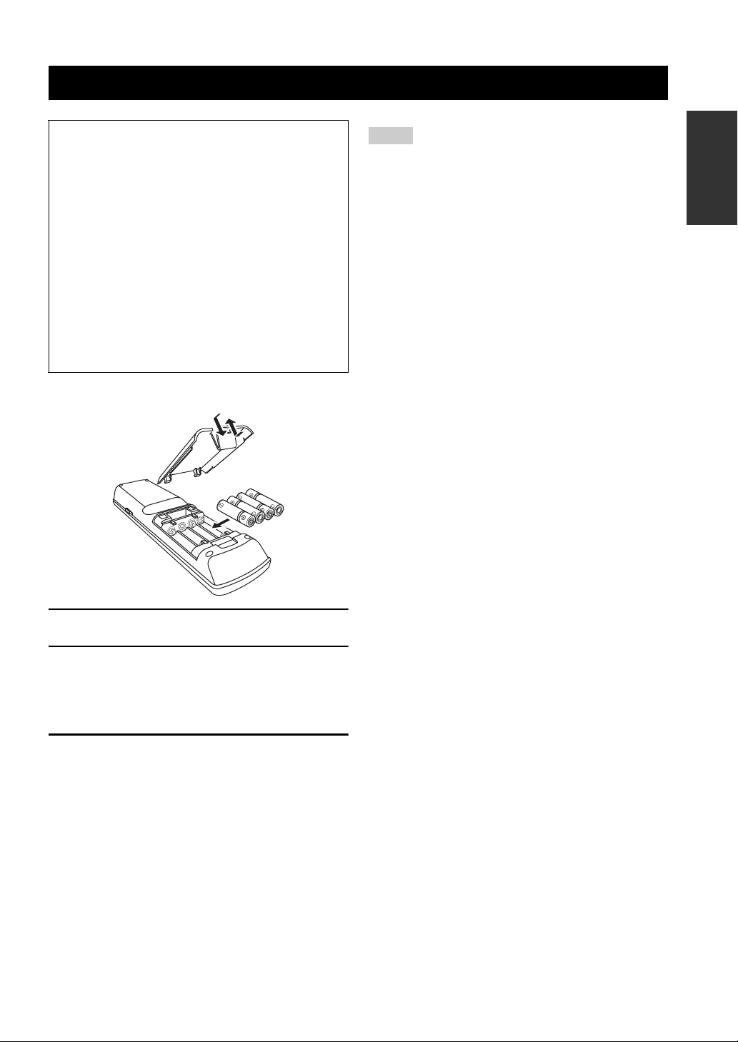
■ Installing batteries in the remote control
1
3
2
Notes
• Change all of the batteries if you notice the following
conditions:
– the operation range of the remote control decreases.
– the transmit indicator does not flash or its light becomes dim.
• Do not use old batteries together with new ones.
• Do not use different types of batteries (such as alkaline and
manganese batteries) together. Read the packaging carefully as
these different types of batteries may have the same shape and
color.
• If the batteries have leaked, dispose of them immediately. Avoid
touching the leaked material or letting it come into contact with
clothing, etc. Clean the battery compartment thoroughly before
installing new batteries.
• Do not throw away batteries with general house waste; dispose
of them correctly in accordance with your local regulations.
• If the remote control is without batteries for more than 2
minutes, or if exhausted batteries remain in the remote control,
the contents of the memory may be cleared. When the memory
is cleared, insert new batteries, set up the remote control code
and program any acquired functions that may have been
cleared.
INTRODUCTION
1 Take off the battery compartment cover.
2 Insert the four supplied batteries
(AAA, LR03, UM-4) according to the polarity
markings (+ and –) on the inside of the
battery compartment.
3 Snap the battery compartment cover back
into place.
9 En
Page 10
QUICK START GUIDE
Quick start guide
The following steps describe the easiest way to enjoy DVD movie playback in your home theater.
Front right
Video monitor
Front left
speaker
Center
speaker
DVD player
speaker
Surround left
speaker
Subwoofer
Surround right
Surround back left
speaker
Surround back
Step 1: Set up your speakers
☞
speaker
right speaker
P. 11
Preparation: Check the items
In these steps, you need the following supplied
accessories.
❏ Power cable
The following items are not included in the package of this
unit.
❏ Speakers
❏ Front speaker ..................................... x 2
❏ Center speaker ................................... x 1
❏ Surround speaker .............................. x 4
Select magnetically shielded speakers. The
minimum required speakers are two front speakers.
The priority of the requirement of other speakers is
as follows:
1. Two surround speakers
2. One center speaker
3. One (or two) surround back speaker(s)
❏ Active subwoofer ................................... x 1
Select an active subwoofer equipped with an RCA
input jack.
Step 2: Connect your DVD player
and other components
☞
P. 12
Step 3: Turn on the power and
start playback
☞
P. 13
Enjoy DVD playback!
❏ Speaker cable ......................................... x 7
❏ Subwoofer cable ..................................... x 1
Select a monaural RCA cable.
❏ DVD player .............................................. x 1
Select DVD player equipped with coaxial digital
audio output jack and composite video output
jack.
❏ Video monitor.......................................... x 1
Select a TV monitor, video monitor or projector
equipped with a composite video input jack.
❏ Video cable ............................................. x 2
Select RCA composite video cables.
❏ Digital coaxial audio cable .................... x 1
10 En
Page 11
Step 1: Set up your speakers
Place your speakers in the room and connect them to this
unit.
HDMI
COMPONENT VIDEO
IN4
MONITOR OUT/
BD/HD DVD DVD CBL/SAT
ZONE OUT
A B C
Y
Y
DVR
IN3
P
B
P
B
CBL/
SAT
P
R
P
R
IN2
IN 1 2
REMOTE
DVD
PHONO
GND
IN1
L
BD/
R
HD DVD
OUT
2
DOCK
OUT
1
OUT IN OUT
CD TV
AUDIO
XM
SIRIUS
MD/CD-R
IN
(PLAY)
L
R
CENTERZONE 4 OUT
FRONT(6CH)
SUB SUR.BACK
WOOFER
(8CH)
MULTI CH INPUT
D
V
V
D
D
CD
321
SUBWOOFER PRE OUT Speaker terminals
1 Place your speakers and subwoofer in the
room.
VIDEO
DVD
BD/HD DVD
OUT
(REC)
CENTER
SURROUND
SUB
WOOFER
DIGITAL INPUT
COAXIAL
R
TV
4
2
1
TRIGGER OUT
CBL/SAT
FRONT
SURROUND
PRE OUT
BD/
HD DVD
RS-232C
DVR
SINGLE(SB)
SUR.BACK/
PRESENCE
CBL/
DVD ZONE 4
65
SAT
OUT OUT
ZONE 2
ZONE OUT
DIGITAL OUTPUT
MD/
87
CD-R
ININ
ZONE 3 ZONE
VCR
VIDEO
OPTICAL
NETWORK USB
MONITOR OUT
S VIDEO
ANTENNA
FM
GND
VIDEO
75Ω UNBAL.
SPEAKERS
L
SP1
R
R
+
+
SINGLE
FRONT SURROUND ZONE 2/ZONE 3
L
R
R
+
+
AM
CENTERSURROUND BACK/BI-AMP PRESENCE/ZONE 2/ZONE 3
L
L
R
AC IN
+
AC OUTLETS
SWITCHED
SP2
L
+
Quick start guide
Be sure to connect the left channel (L), right channel
(R), “+” (red) and “–” (black) properly.
Front speakers and center speaker
Loosen Insert
Tighten
INTRODUCTION
2 Connect speaker cables to each speaker.
3 Connect each speaker cable to the
corresponding speaker terminal of this unit.
12 3 4
12 3 4
1 Make sure that this unit and the subwoofer are
unplugged from the AC wall outlets.
2 Twist the exposed wires of the speaker cables
together to prevent short circuits.
3 Do not let the bare speaker wires touch each other.
4 Do not let the bare speaker wires touch any metal
part of this unit.
To the front right
speaker
To the front left
speaker
To the center
speaker
Surround and surround back speakers
To the surround
back
right speaker
To the surround back
left speaker
To the surround
right speaker
To the surround left
speaker
4 Connect the subwoofer cable to the
SUBWOOFER PRE OUT jack of this unit and
the input jack of the subwoofer.
AV receiverSubwoofer
Input jack
Subwoofer cable
SUBWOOFER PRE OUT jack
11 En
Page 12
Quick start guide
USU
S
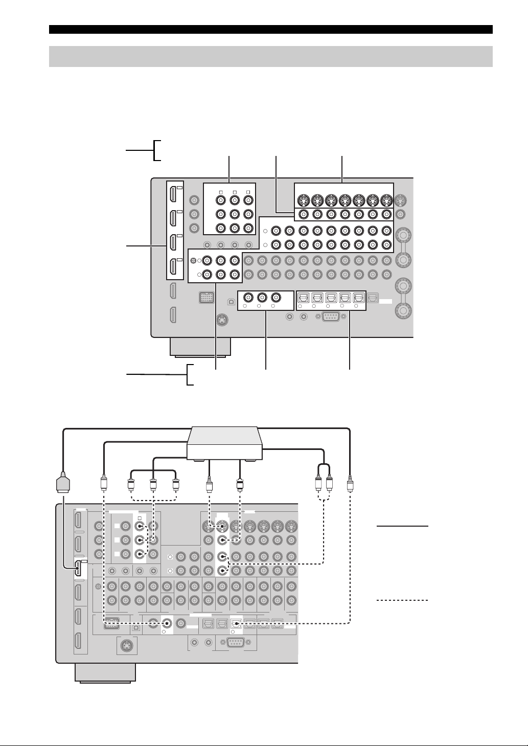
Step 2: Connect your DVD player and other components
VIDEO MONITOR OUTDVD VIDEO
HDMI
COMPONENT VIDEO
IN4
MONITOR OUT/
BD/HD DVD DVD CBL/SAT
ZONE OUT
A B C
Y
Y
DVR
IN3
P
B
P
B
CBL/
SAT
P
R
P
R
IN2
IN 1 2
REMOTE
DVD
PHONO
GND
IN1
L
BD/
R
HD DVD
OUT
2
DOCK
OUT
1
DVD DIGITAL INPUT
OUT IN OUT
CD TV
AUDIO
XM
SIRIUS
MD/CD-R
IN
(PLAY)
L
R
CENTERZONE 4 OUT
FRONT(6CH)
SUB SUR.BACK
WOOFER
(8CH)
MULTI CH INPUT
R
D
V
V
D
D
CD
321
COAXIAL
Make sure that this unit and the DVD
player are unplugged from the AC
wall outlets.
1 Connect the digital coaxial audio cable to the
digital coaxial audio output jack of your DVD
player and the DVD DIGITAL INPUT COAXIAL
jack of this unit.
VIDEO
DVD
BD/HD DVD
OUT
(REC)
CENTER
SURROUND
SUB
WOOFER
DIGITAL INPUT
COAXIAL
TV
4
2
1
TRIGGER OUT
CBL/SAT
FRONT
SURROUND
PRE OUT
BD/
65
HD DVD
RS-232C
DVR
OUT OUT
SINGLE(SB)
ZONE 2
SUR.BACK/
PRESENCE
DIGITAL OUTPUT
CBL/
MD/
DVD ZONE 4
87
SAT
CD-R
ZONE OUT
ININ
ZONE 3 ZONE
VCR
VIDEO
OPTICAL
NETWORK USB
MONITOR OUT
S VIDEO
ANTENNA
FM
GND
VIDEO
75Ω UNBAL.
SPEAKERS
L
SP1
R
R
+
+
SINGLE
FRONT SURROUND ZONE 2/ZONE 3
L
R
R
+
+
AM
CENTERSURROUND BACK/BI-AMP PRESENCE/ZONE 2/ZONE 3
L
SP2
L
R
AC IN
+
AC OUTLETS
SWITCHED
L
+
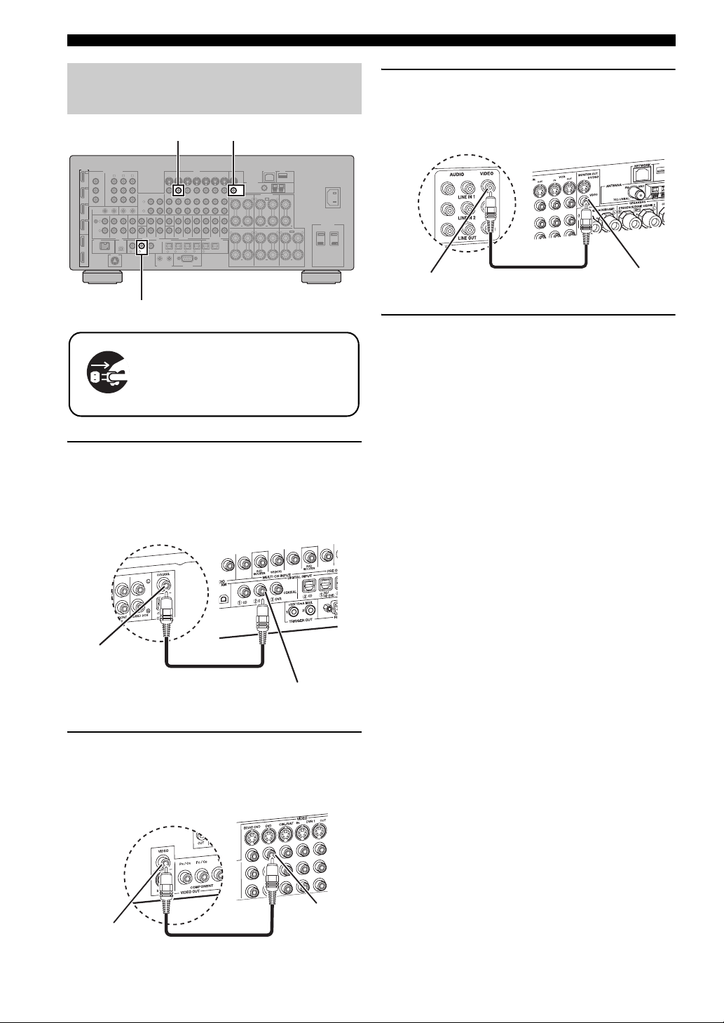
3 Connect the video cable to the VIDEO
MONITOR OUT jack of this unit and the video
input jack of your video monitor.
Video monitor
Video input jack
Video cable
AV receiver
VIDEO MONITOR
OUT jack
4 Connect the supplied power cable to this unit
and then plug of the power cable and other
components into the AC wall outlet.
y
For details about connecting the power cable, see page 30.
■ For other connections
• Other speaker combinations ☞ P. 17
• Information on jacks and cable plugs ☞ P. 20
• Information on HDMI™ ☞ P. 21
Digital coaxial
audio output
jack
DVD player
Digital coaxial audio
cable
AV receiver
DVD DIGITAL INPUT
COAXIAL jack
2 Connect the video cable to the composite
video output jack of your DVD player and
DVD VIDEO jack of this unit.
AV receiver
DVD VIDEO jack
Composite video
output jack
DVD player
Video cable
• TV monitor or projector ☞ P. 23
• Other components ☞ P. 24
• External amplifier ☞ P. 26
• Multi-format player or external
decoder ☞ P. 27
• Yamaha iPod universal dock or
Bluetooth wireless audio receiver ☞ P. 27
• FM/AM antennas ☞ P. 29
• XM Mini-Tuner Home Dock ☞ P. 61
• SiriusConnect tuner ☞ P. 65
•Network ☞ P. 28
• USB device ☞ P. 28
12 En
Page 13
Quick start guide
Step 3: Turn on the power and start playback
Check the type of the connected speakers.
If the speakers are 6-ohm speakers, set “SPEAKER
IMP.” to “6Ω MIN” before using this unit (page 31).
You can also use 4-ohm speakers as the front speakers
(page 130).
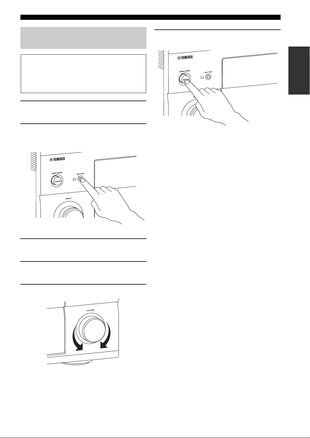
1 Turn on the video monitor connected to this
unit.
2 Press BMASTER ON/OFF inward to the ON
position on the front panel.
6 To set this unit to the standby mode, press
AMAIN ZONE ON/OFF.
INTRODUCTION
y
For details about turning on/off this unit and the standby
mode, see page 31.
■ For other operations
• Optimizing the speaker parameters
automatically ☞ P. 35
• Basic playback operations ☞ P. 42
• Sound field programs ☞ P. 46
• Pure high-fidelity sounds ☞ P. 54
3 Rotate the
source to “DVD”.
L
INPUT selector to set the input
4 Start playback of the desired DVD on your
player.
5 Rotate
P
VOLUME to adjust the volume.
• FM/AM radio tuning ☞ P. 56
• XM Satellite Radio tuning ☞ P. 61
• SIRIUS Satellite Radio tuning ☞ P. 65
• iPod playback ☞ P. 73
• Playback via USB or network ☞ P. 75
• Bluetooth component playback ☞ P. 71
13 En
Page 14
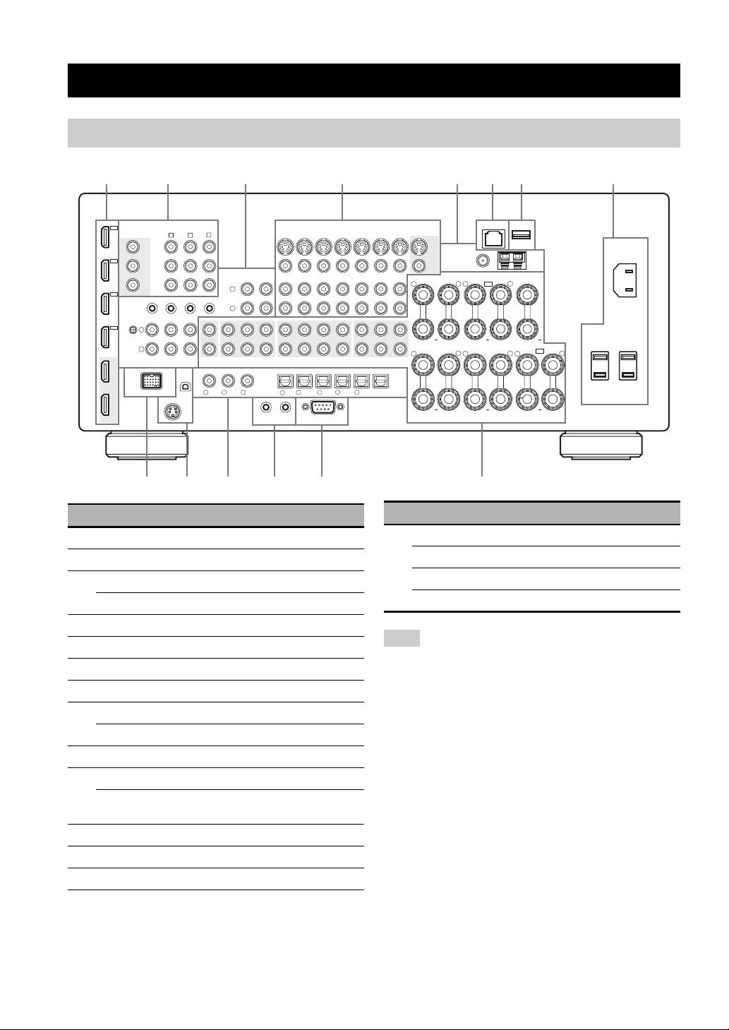
Rear panel
Connections
231456 8
HDMI
HD DVD
1 HDMI jacks 21
2 COMPONENT VIDEO jacks 20
3 Audio component jacks 20
REMOTE IN/OUT jacks 27, 124
4 Video component jacks 20
5 ANTENNA terminals 29
6 NETWORK port 28
7 USB port 28
8 AC IN 30
AC OUTLET(S) 30
9 DOCK terminal 27
0 XM jack (U.S.A. and Canada models only) 61
SIRIUS jack
(U.S.A. and Canada models only)
A DIGITAL INPUT/OUTPUT jacks 20
B TRIGGER OUT jacks 126
C RS-232C terminal —
IN4
DVR
IN3
CBL/
SAT
IN2
DVD
IN1
BD/
OUT
OUT
2
1
MONITOR OUT/
ZONE OUT
Y
P
B
P
R
REMOTE
GND
DOCK
COMPONENT VIDEO
BD/HD DVD DVD CBL/SAT
Y
P
B
P
R
IN 1 2
PHONO
L
R
9
(PLAY)
FRONT(6CH)
(8CH)
321
IN
D
MD/CD-R
V
COAXIAL
R
OUT
(REC)
SURROUND
DIGITAL INPUT
1
TRIGGER OUT
BD/HD DVD
CENTER
SUB
WOOFER
4
2
TV
A B C
OUT IN OUT
CD TV
AUDIO
XM
SIRIUS
CD
L
R
CENTERZONE 4 OUT
SUB SUR.BACK
WOOFER
MULTI CH INPUT
VD
D
BCA0
Name Page
DVD
CBL/SAT
FRONT
SURROUND
PRE OUT
BD/
DVD ZONE 4
65
HD DVD
RS-232C
VIDEO
SINGLE(SB)
SUR.BACK/
PRESENCE
65
DVR
ZONE 2
CBL/
87
SAT
7
SINGLE
ANTENNA
75Ω UNBAL.
L
R
L
R
NETWORK USB
FM
GND
SPEAKERS
SP1
+
+
AM
CENTERSURROUND BACK/BI-AMP PRESENCE/ZONE 2/ZONE 3
L
+
SP2
L
R
L
+
VCR
OUT OUT
ININ
ZONE 3 ZONE
ZONE OUT
DIGITAL OUTPUT
OPTICAL
MD/
CD-R
MONITOR OUT
S VIDEO
VIDEO
R
+
VIDEO
FRONT SURROUND ZONE 2/ZONE 3
R
+
D
Name Page
D MULTI CH INPUT jacks 27
PRE OUT jacks 26
ZONE OUT jacks 124
Speaker terminals 17
Note
The RS-232C terminal is a control expansion terminal for
factory use only. Consult your dealer for details.
AC OUTLETS
SWITCHED
AC IN
14 En
Page 15
Connections
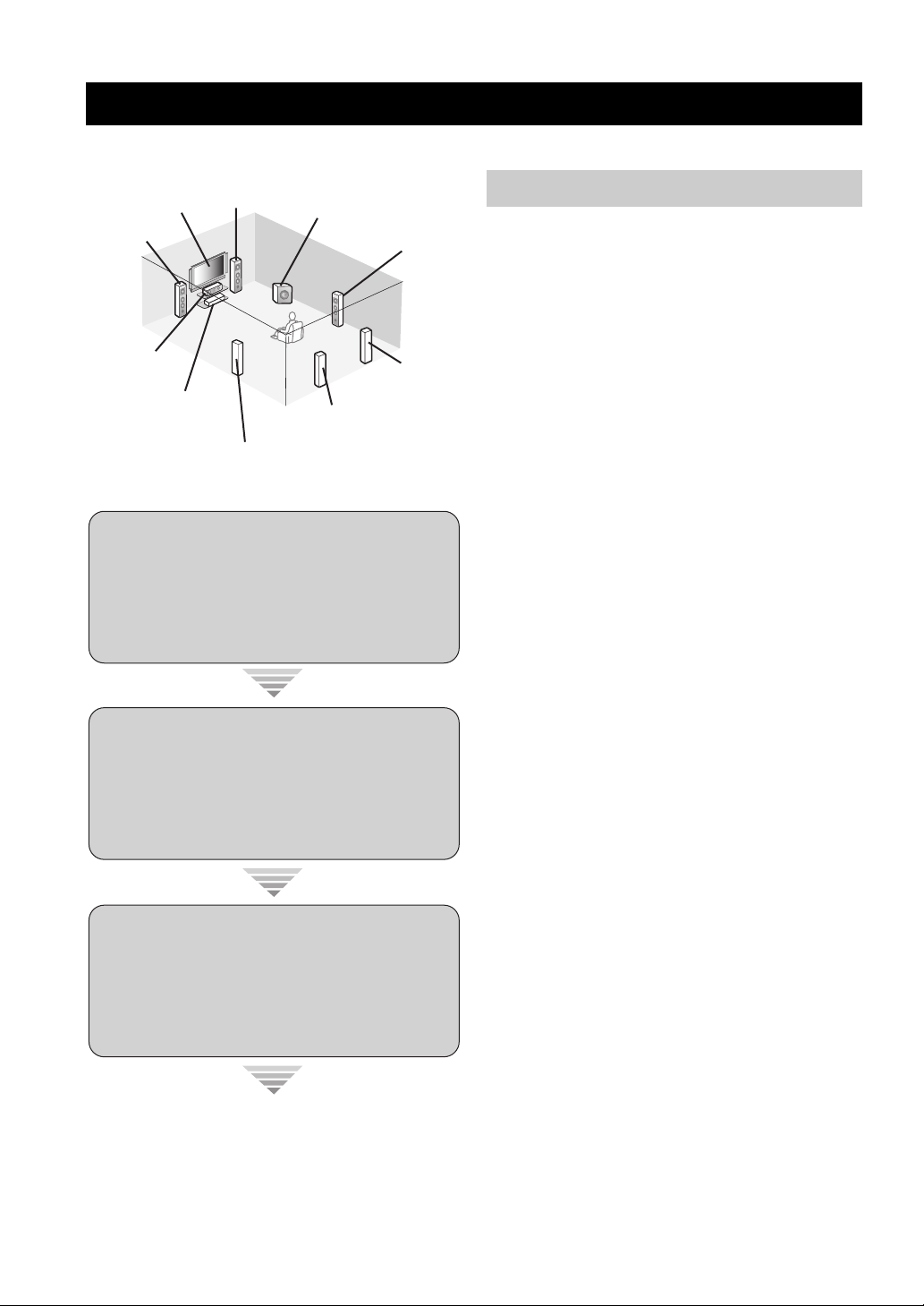
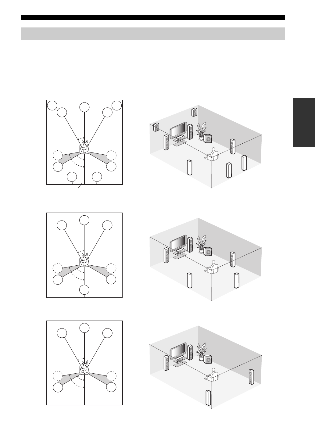
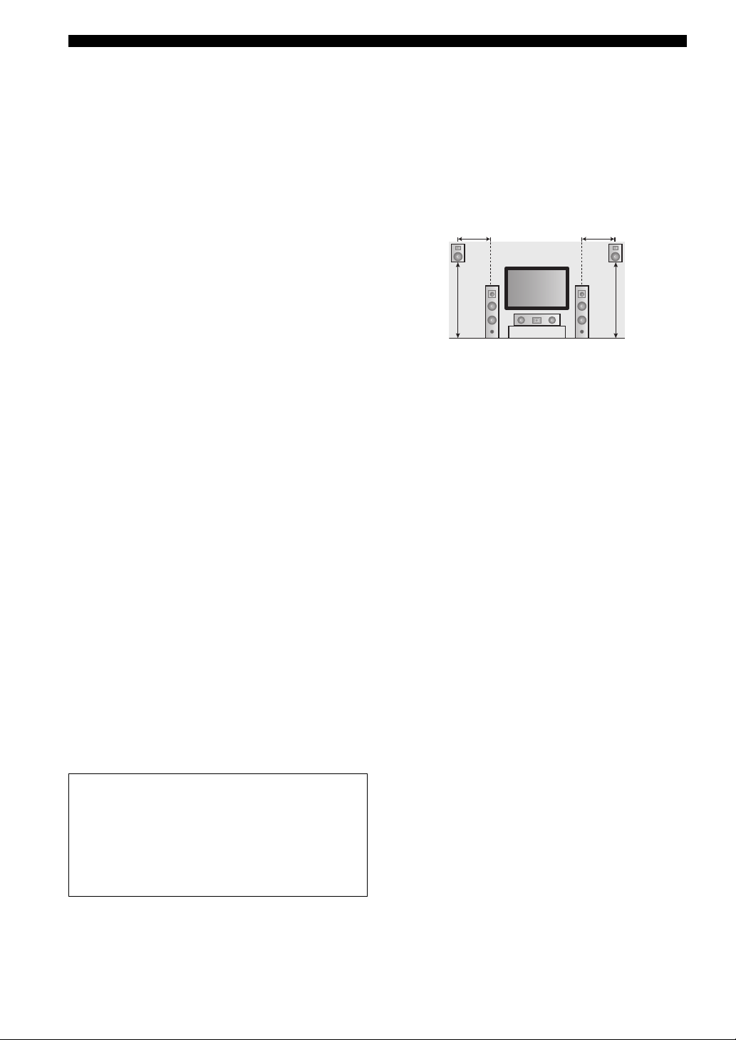
Placing speakers
The speaker layout below shows the speaker setting we recommend.
y
• 7.1-channel speaker layout is highly recommended for playback of the high definition digital audio sources (Dolby TrueHD, DTS-HD
Master Audio, etc.) with sound field programs.
• We recommend that you add the presence speakers for the effect sounds of the CINEMA DSP sound field program.
• The surround back speakers and presence speakers do not output sound simultaneously.
7.1-channel speaker layout (plus presence speakers)
PL
FL
SL
SL
80˚
SBL
C
30˚
60˚
30 cm (12 in) or more
6.1-channel speaker layout
FL
SL
SL
C
30˚
60˚
80˚
SB
SBR
PR
FR
PL
FL
PR
FR
SW
SR
PREPARATION
C
SR
SR
SL
SBR
SBL
FR
FR
FL
SW
SR
C
SR
SR
SL
SB
5.1-channel speaker layout
FL
SL
SL
C
30˚
60˚
80˚
FR
FR
FL
SW
C
SR
SR
SR
SL
15 En
Page 16
Connections
■ Speaker types
Front left and right speakers (FL and FR)
The front speakers are used for the main source sound plus
effect sounds. Place these speakers at an equal distance from
the ideal listening position. The distance of each speaker
from each side of the video monitor should be the same.
Center speaker (C)
The center speaker is for the center channel sounds
(dialog, vocals, etc.). If for some reason it is not practical
to use a center speaker, you can do without it. Best results,
however, are obtained with the full system.
Surround left and right speakers (SL and SR)
The surround speakers are used for effect and surround
sounds.
For 5.1-channel speaker layout, place these speakers
farther back compared with the placement in the 7.1channel speaker layout.
Surround back left and right speakers (SBL and
SBR)/Surround back speaker (SB)
The surround back speakers supplement the surround
speakers and provide more realistic front-to-back
transitions.
For 6.1-channel speaker layout, surround back left and
right channel signals are mixed down and output at the
single surround back speaker by configuring the
“Surround Back” setting (
For 5.1-channel speaker layout, surround back left and
right channel signals are output at the surround left and
right speakers by configuring the “Surround Back” setting
page 93).
(
Subwoofer (SW)
The use of a subwoofer with a built-in amplifier, such as
the Yamaha Active Servo Processing Subwoofer System,
is effective not only for reinforcing bass frequencies from
any or all channels, but also for reproducing the high
fidelity sound of the LFE (low-frequency effect) channel
included in bitstreams and multi-channel PCM sources.
The position of the subwoofer is not so critical, because
low bass sounds are not highly directional. But it is better
to place the subwoofer near the front speakers. Turn it
slightly toward the center of the room to reduce wall
reflections.
page 93).
■ Presence left and right speakers (PL and
PR)
The presence speakers supplement the sound from the front
speakers with extra ambient effects produced by the sound
field programs (page 46). We recommend that you use the
presence speakers especially for the CINEMA DSP sound
field programs. To use the presence speakers, connect the
“
PRPL
FR
Front
1.8 m (6 ft)
speakers to SP1 speaker terminals and then set
”
Presence
1.8 m (6 ft)
to “Ye s” (
0.5 to 1 m (1 to 3 ft) 0.5 to 1 m (1 to 3 ft)
FL
page 93
).
C
For other speaker combinations
You can enjoy multi-channel sources with sound field
programs by using a speaker combination other than
the 7.1/6.1/5.1-channel speaker combinations.
Use the automatic setup feature (page 35) or set the
“Speaker” parameters (
page 93). to output the surround
sounds at the connected speakers.
16 En
Page 17
Connections
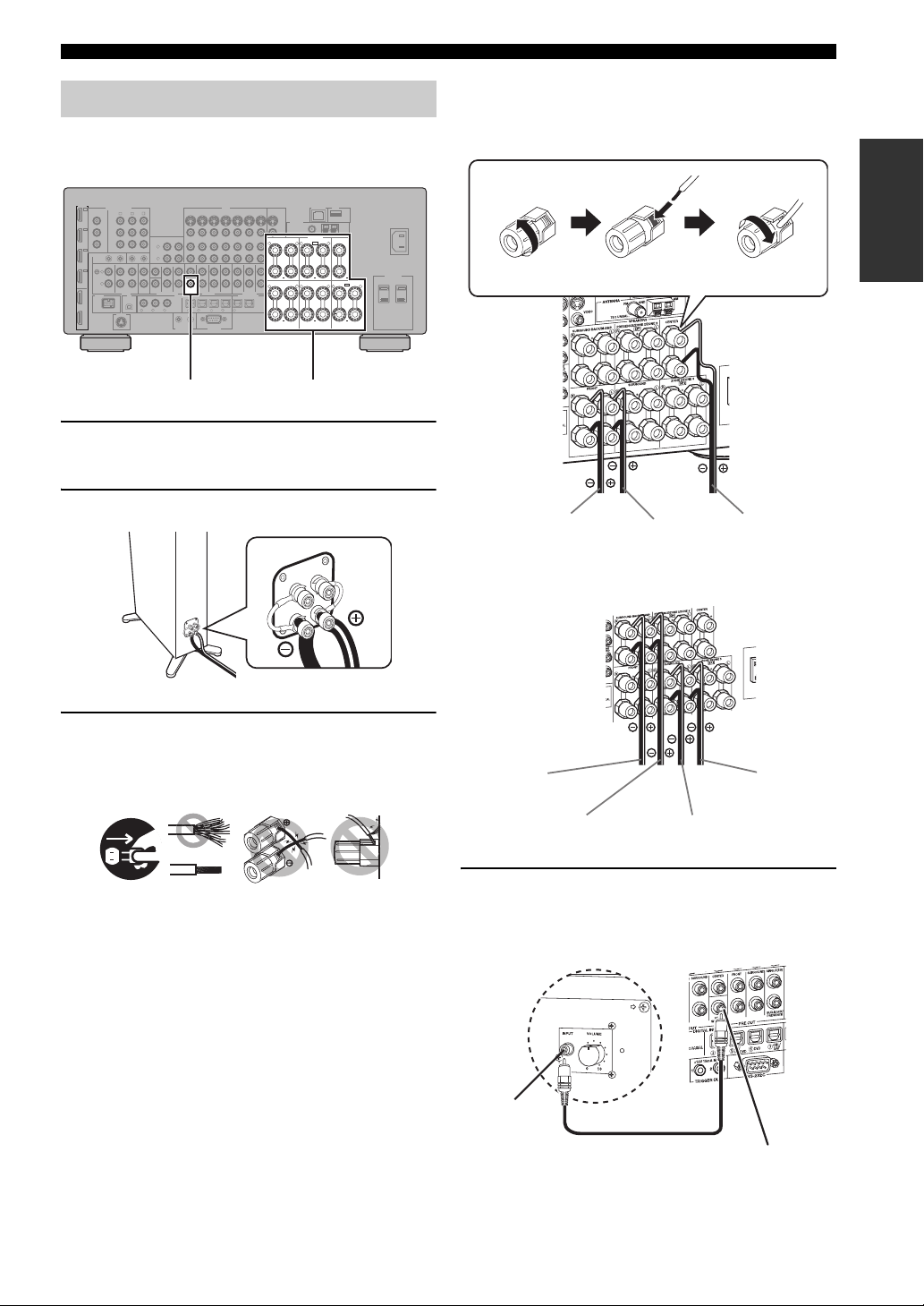
Connecting speakers
Be sure to connect the left channel (L), right channel (R), “+” (red) and “–” (black) properly. If the connections are faulty,
this unit cannot reproduce the input sources accurately.
Caution
• Before connecting the speakers, make sure that this unit is turned off (page 31).
• Do not let the bare speaker wires touch each other or do not let them touch any metal part of this unit. This could
damage this unit and/or speakers.
• Use magnetically shielded speakers. If this type of speaker still creates interference with the monitor, place the
speakers away from the monitor.
• If you are to use 6-ohm speakers, be sure to set “SPEAKER IMP.” to “6Ω MIN” before using this unit (page 31).
You can also use 4-ohm speakers as the front speakers (page 130).
Notes
• A speaker cord is actually a pair of insulated cables running side by side. Cables are colored or shaped differently, perhaps with a
stripe, groove or ridge. Connect the striped (grooved, etc.) cable to the “+” (red) terminals of this unit and your speaker. Connect the
plain cable to the “–” (black) terminals.
• You can connect both surround back and presence speakers to this unit, however they do not output sound simultaneously. This unit
automatically switches the presence speakers and surround back speakers depending on the input sources and the selected sound field
programs.
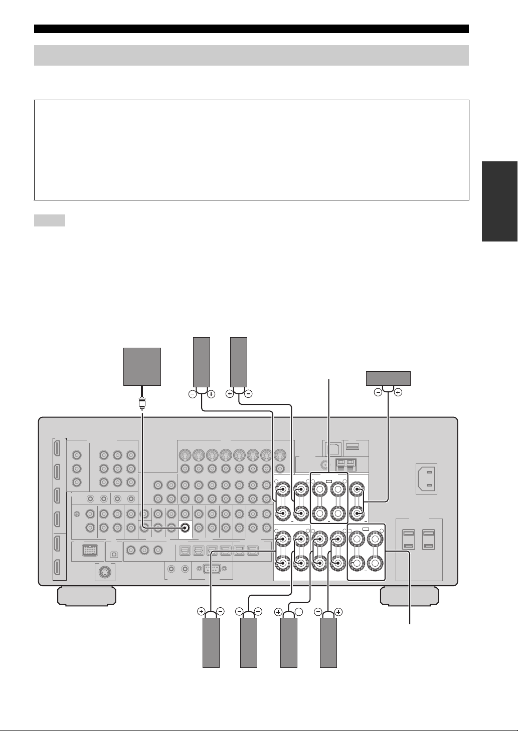
■ 7.1-channel speaker connection
Surround back speakers
Right
Subwoofer
Left
Presence speakers
(page 16) or
Zone 2/Zone 3
speakers
(page 124)
Center speaker
PREPARATION
R
WOOFER
SUB
R
Left
Front speakers Surround speakers
SPEAKERS
L
R
+
SINGLE
FRONT SURROUND ZONE 2/ZONE 3
L
R
+
CENTERSURROUND BACK/BI-AMP PRESENCE/ZONE 2/ZONE 3
L
SP1
+
+
+
SP2
L
R
+
Zone 2/Zone 3 speakers
(page 124)
LeftRightRight
L
17 En
Page 18
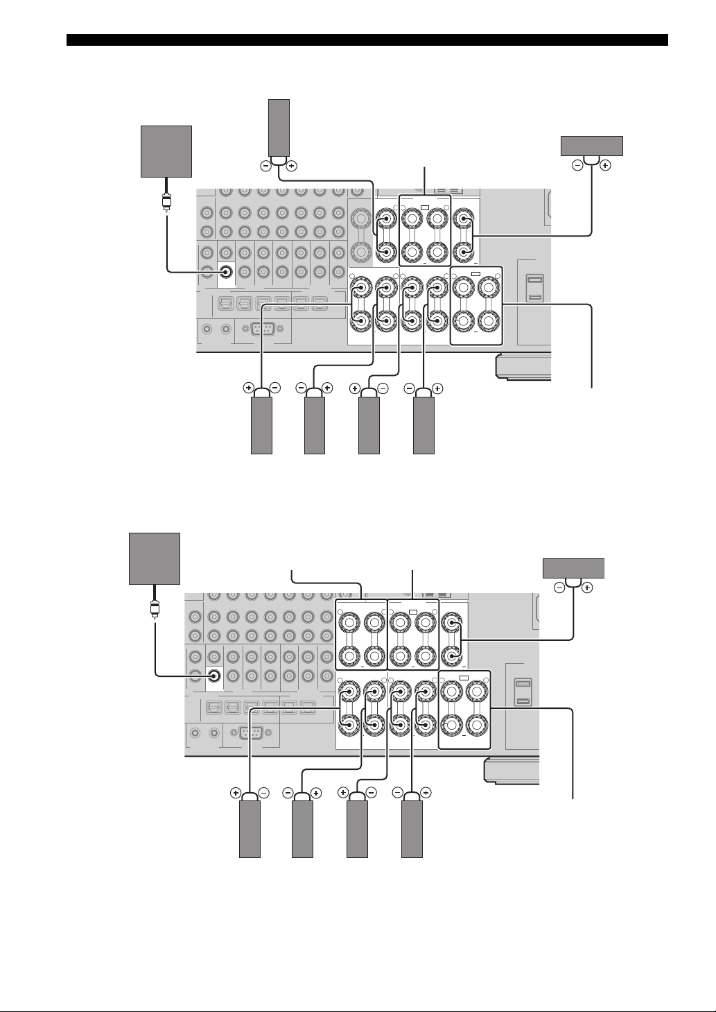
Connections
■ 6.1-channel speaker connection
Surround back speaker
Subwoofer
SUB
WOOFER
Right Right
Front speakers
■ 5.1-channel speaker connection
Left
Presence speakers
(page 16) or
Zone 2/Zone 3 speakers
(page 124)
SPEAKERS
L
SP1
R
+
SINGLE
FRONT SURROUND ZONE 2/ZONE 3
R
L
R
+
+
Left
Surround speakers
Center speaker
CENTERPRESENCE/ZONE 2/ZONE 3
L
+
SP2
L
R
L
+
Zone 2/Zone 3
speakers
(page 124)
Subwoofer
WOOFER
Front speakers for the
bi-amplification
connections
(page 19)
R
SUB
R
Presence speakers
(page 16) or
Zone 2/Zone 3 speakers
(page 124)
SPEAKERS
L
R
+
SINGLE
FRONT SURROUND ZONE 2/ZONE 3
L
R
+
CENTERSURROUND BACK/BI-AMP PRESENCE/ZONE 2/ZONE 3
L
SP1
+
+
+
SP2
L
R
+
Center speaker
L
Zone 2/Zone 3
speakers
(page 124)
Right
Right
LeftLeft
Surround speakersFront speakers
18 En
Page 19
Connections
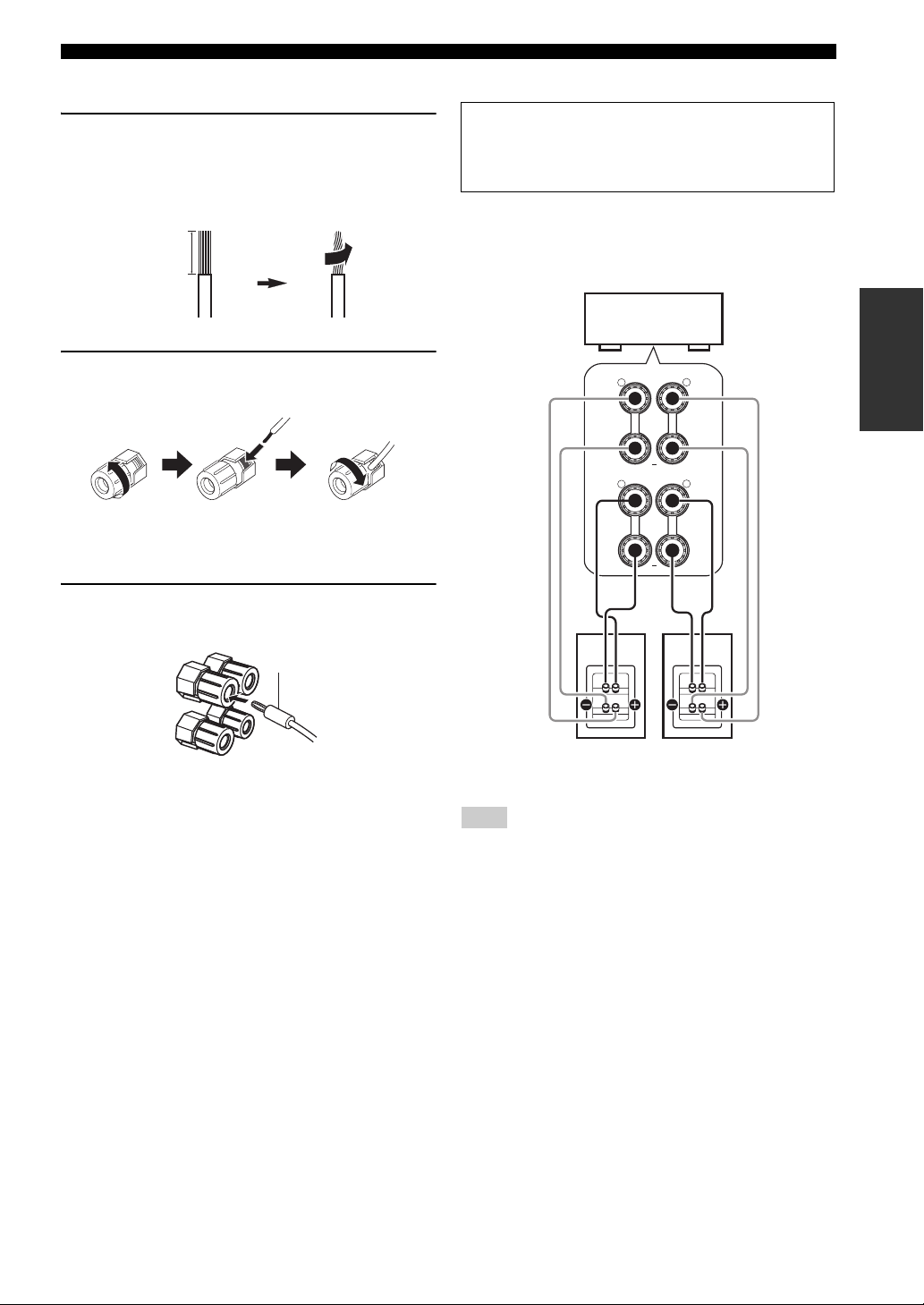
■ Connecting the speaker cable
1 Remove approximately 10 mm (0.4 in) of
insulation from the end of each speaker
cable and then twist the exposed wires of the
cable together to prevent short circuits.
10 mm (0.4 in)
2 Loosen the knob, insert one bare wire into
the hole and then tighten the knob.
Loosen Insert Tighten
■ Connecting the banana plug
Tighten the knob and then insert the banana plug
into the end of the terminal.
■ Using bi-amplification connections
Caution
Remove the shorting bars or bridges of your speakers to
separate the LPF (low pass filter) and HPF (high pass filter)
crossovers.
You can make bi-amplification connections to one speaker
system which supports bi-amplification connection as
shown below. To activate the connections, configure the
“BI-AMP” setting (page 131).
This unit
SURROUND BACK/BI-AMP
R
R
FRONT
L
+
SINGLE
L
+
PREPARATION
Banana plug
LeftRight
Front speakers
Note
When you make the conventional connection with the speakers,
make sure that the shorting bars are put into the terminals of the
speakers appropriately. Refer to the instruction manuals of the
speakers for details.
19 En
Page 20
Connections
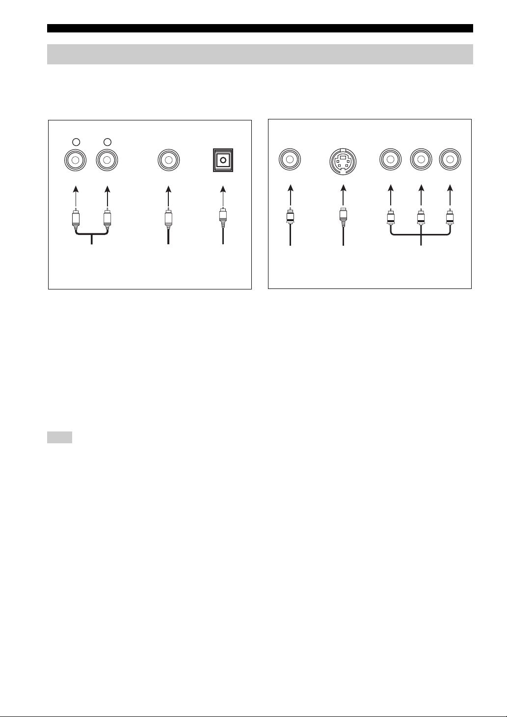
Information on jacks and cable plugs
This unit has three types of audio jacks, three types of video jacks and HDMI jacks. You can choose the connection
method depending on the component to be connected.
■ Audio jacks
AUDIO
L
L
Left and right
analog audio
cable plugs
R
(Red)(White) (Orange)
R
DIGITAL
COAXIAL
C
Coaxial
digital audio
cable plug
AUDIO jacks
For conventional analog audio signals transmitted via left
and right analog audio cables. Connect red plugs to the
right jacks and white plugs to the left jacks.
COAXIAL jacks
For digital audio signals transmitted via coaxial digital
audio cables.
OPTICAL jacks
For digital audio signals transmitted via optical digital
audio cables.
Note
You can use the digital jacks to input PCM, Dolby Digital and
DTS bitstreams. When you connect components to both the
COAXIAL and OPTICAL jacks, priority is given to the signals
input at the COAXIAL jack. All digital input jacks are
compatible with up to 96-kHz sampling digital signals.
DIGITAL
OPTICAL
O
Optical
digital
audio cable
plug
■ Video jacks
VIDEO S VIDEO
(Yellow) (Green) (Blue) (Red)
V
Composite
video cable
plug
S
S-video
cable plug
VIDEO jacks
For conventional composite video signals transmitted via
composite video cables.
S VIDEO jacks
For S-video signals, separated into the luminance (Y) and
chrominance (C) video signals transmitted on separate
wires of S-video cables.
COMPONENT VIDEO jacks
For component video signals, separated into the
luminance (Y) and chrominance (P
transmitted on separate wires of component video cables.
y
This unit is equipped with the video conversion function.
(page 22)
COMPONENT VIDEO
Y
Y
Component
video cable
plugs
B, PR) video signals
P
B
P
PB
R
P
R
20 En
Page 21
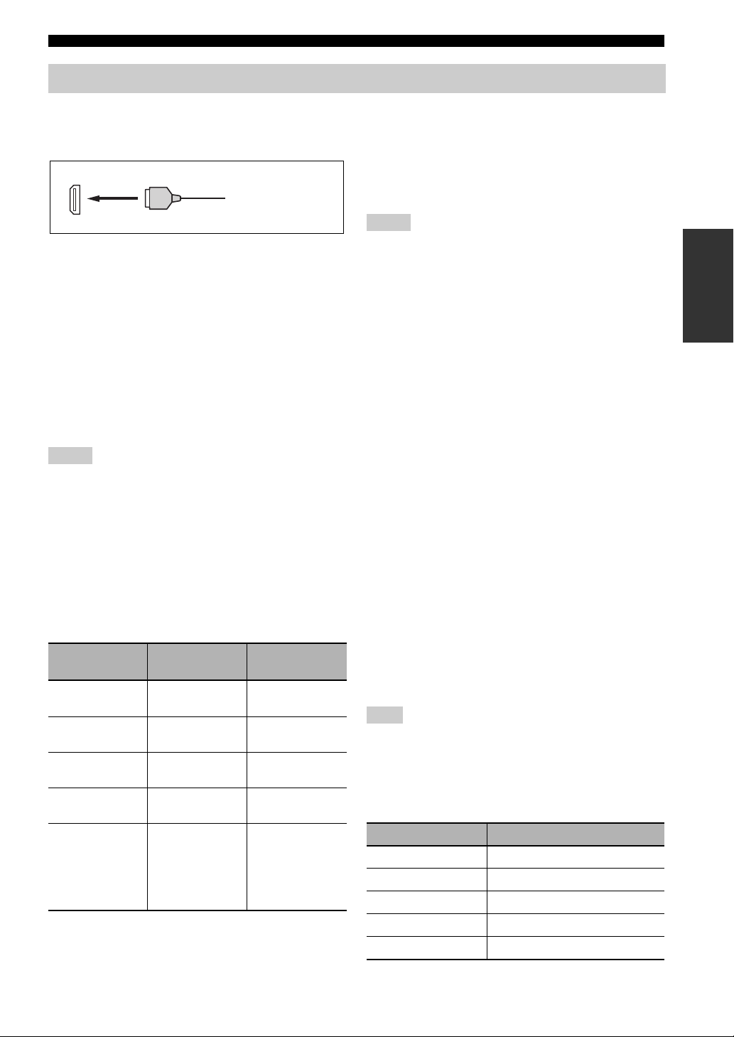
Connections
Information on HDMI™
This unit has four HDMI input jacks and two HDMI output jacks for digital audio and video signal input/output.
■ HDMI jack and cable plug
HDMI
HDMI cable plug
y
• We recommend that you use a commercially available HDMI cable
shorter than 5 meters (16 feet) with the HDMI logo printed on it.
• Use a conversion cable (HDMI jack
unit to other DVI components.
• You can check the potential problem about the HDMI connection
(page 44).
• If you set “Mode” in “Standby Through” to “Last” or “Fix”, this
unit allows the HDMI signals input at an HDMI IN jack to pass
through this unit and output at an HDMI OUT jack (page 101).
• This unit is equipped with two HDMI OUT jacks. You can select
the active HDMI OUT jack(s) (
• This unit is equipped with the video conversion function (page 22).
↔
DVI-D jack) to connect this
page 43
).
Notes
• Do not disconnect or connect the cable or turn off the power of
the HDMI components connected to the HDMI OUT jacks of
this unit while data is being transferred. Doing so may disrupt
playback or cause noise.
• The HDMI OUT jacks output the audio signals input at the
HDMI input jacks only.
• If you turn off the video monitor connected to the HDMI OUT
jacks via a DVI connection, the connection may fail.
■ HDMI signal compatibility with this unit
Audio signals
Audio signal
types
2ch Linear
PCM
Multi-ch
Linear PCM
DSD 2/5.1ch,
Bitstream Dolby Digital,
Bitstream (High
definition audio)
y
• If the input source component can decode the bitstream audio
signals of audio commentaries, you can play back the audio sources
with the audio commentaries mixed down by using the following
Audio signal
formats
2ch, 32-192 kHz,
16/20/24 bit
8ch, 32-192 kHz,
16/20/24 bit
2.8224 MHz,1 bit
DTS
Dolby TrueHD,
Dolby Digital Plus,
DTS-HD Master
Audio, DTS-HD
High Resolution
Audio
Compatible
media
CD, DVD-Video,
DVD-Audio, etc.
DVD-Audio, etc.
SA-CD, etc.
DVD-Video, etc.
Blu-ray Disc,
HD DVD, etc.
connections:
– multi-channel analog audio input (page 27)
– DIGITAL INPUT OPTICAL (or COAXIAL)
• Refer to the instruction manuals of the input source component,
and set the component appropriately.
Notes
• When CPPM copy-protected DVD audio is played back, video and
audio signals may not be output depending on the type of the DVD
player.
• This unit is not compatible with HDCP-incompatible HDMI or
DVI components.
• To decode the audio bitstream signals on this unit, set the input
source component appropriately so that the component outputs the
audio bitstream signals directly (does not decode the bitstream
signals on the component).
• This unit is not compatible with the audio commentary features (for
example, the special audio contents downloaded via Internet) of
Blu-ray Disc or HD DVD. This unit does not play back the audio
commentaries of the Blu-ray Disc or HD DVD contents.
Video signals
This unit is compatible with the video signals of the
following resolutions:
– 480i/60 Hz
– 576i/50 Hz
– 480p/60 Hz
– 576p/50 Hz
– 720p/60 Hz, 50 Hz
– 1080i/60 Hz, 50 Hz
– 1080p/60 Hz, 50 Hz, 24Hz
Compatibility with Deep Color and x.v.Color
video signals
This unit accepts Deep Color (30 or 36-bit) and x.v.Color
video signals. To output those video signals from the
HDMI OUT jacks without any processing, set “HDMI `
HDMI” (page 99) to “Through”.
Note
If the video monitor is not compatible with Deep Color or
x.v.Color video signals, the video source may not be played
back correctly.
■ Default input assignment of HDMI input
jacks
HDMI input jack Assigned input source
IN1 BD/HD DVD
IN2 DVD
IN3 CBL/SAT
IN4 DVR
Front HDMI IN jack V-AUX
PREPARATION
21 En
Page 22
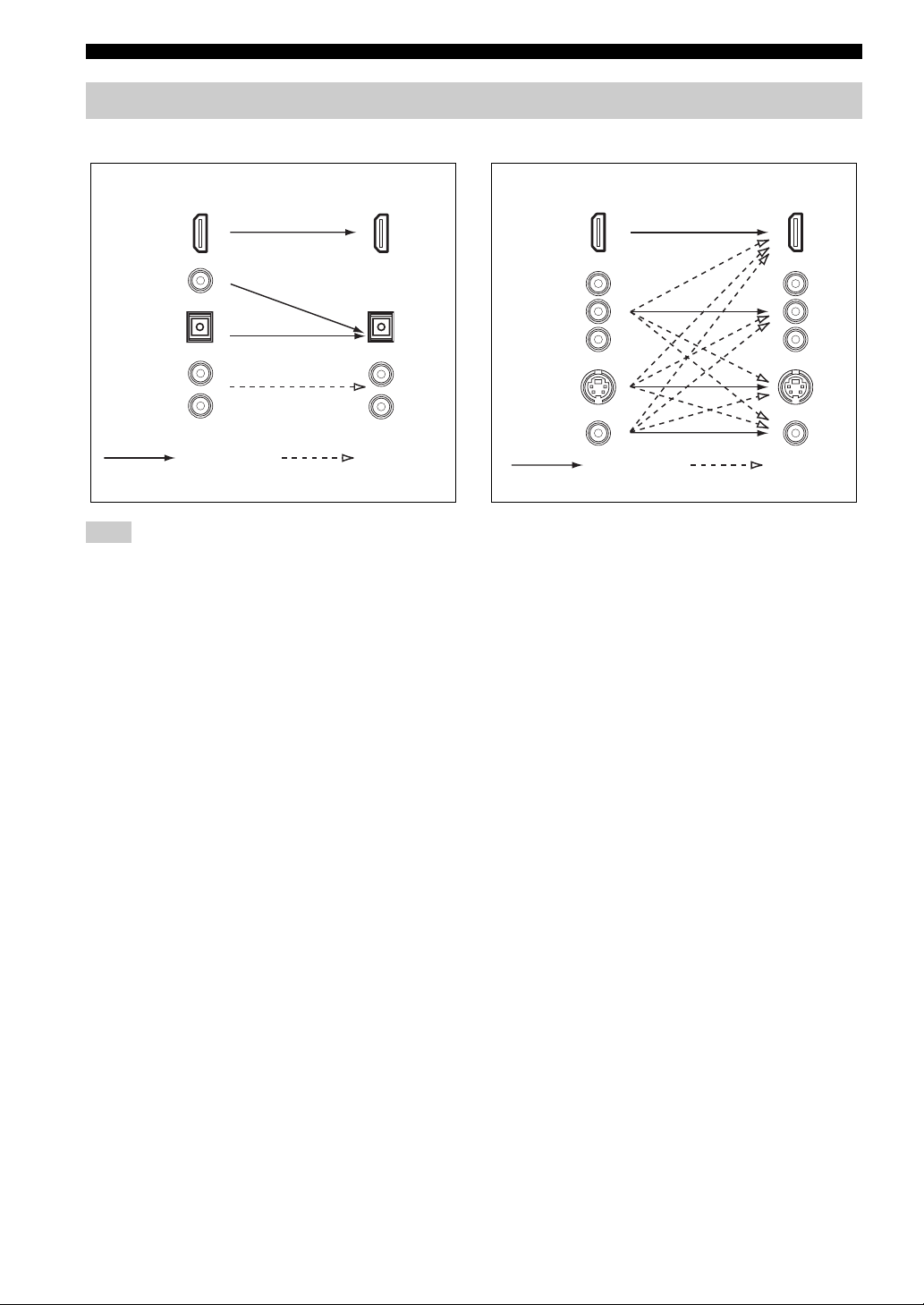
Connections
Audio and video signal flow
■ Audio signal flow
OutputInput
HDMI
DIGITAL AUDIO
(COAXIAL)
DIGITAL AUDIO
(OPTICAL)
AUDI O
Digital
Note
Only the HDMI input jacks support multi-channel PCM, DSD,
Dolby TrueHD, Dolby Digital Plus, DTS-HD Master Audio and
DTS-HD High Resolution Audio signal inputs.
Analog
■ Video signal flow
OutputInput
HDMI
COMPONENT
VIDEO
S VIDEO
VIDEO
Through
y
• Analog-to-HDMI video conversion is always possible unless
video signals are being input at the HDMI input jacks or 1080presolution analog video signals are being input.
• To set the analog-to-analog video conversion or change the
other video settings, configure the “Video” parameters
(
page 99).
• If different analog video signals are input concurrently, the
following priority order will be applied:
(1) COMPONENT VIDEO, (2) S VIDEO, (3) VIDEO
Video
conversion
22 En
Page 23
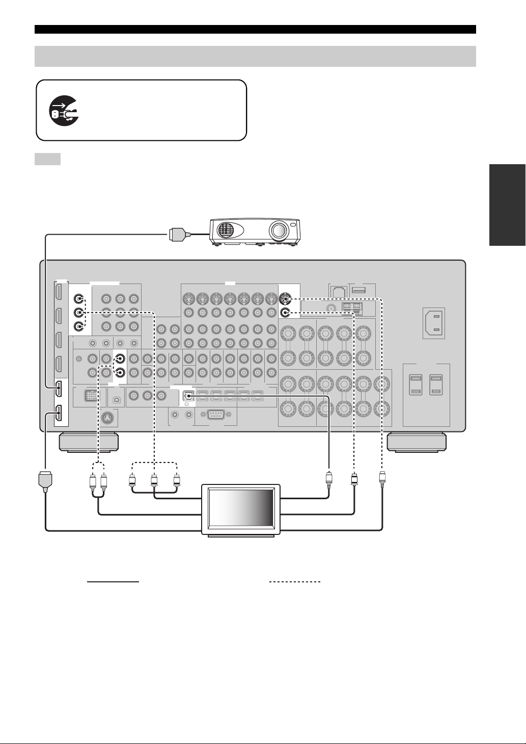
Connecting a TV monitor or projector
Make sure that this unit and other
components are unplugged from the
AC wall outlets.
Note
If you turn off the video monitor connected to the HDMI OUT
jacks via a DVI connection, the connection may fail. In this
case, the HDMI indicator flashes irregularly.
HDMI in
Connections
y
• To select the types of the audio signals output at the HDMI
OUT jacks, configure the “Audio Output” setting (
• To assign the COMPONENT VIDEO (MONITOR OUT/ZONE
OUT) jacks to the main zone or another zone, configure the
“Component Assign” setting (
page 103).
Projector
page 101).
PREPARATION
HDMI
OUT
2
OUT
1
MONITOR OUT/
ZONE OUT
Y
P
B
P
R
COMPONENT VIDEO
AUDIO
L R
VIDEO
TV
DIGITAL INPUT
TV
4
Y
PRPB
MONITOR OUT
S VIDEO
VIDEO
O
S
V
Optical outComponent video in
Video inAudio out
HDMI in
TV
S-video in
Recommended connections Alternative connections
23 En
Page 24
Connections
Connecting other components
■ Connecting audio and video components
This unit has three types of audio jacks, three types of video jacks and HDMI jacks. You can choose the connection
method depending on the component to be connected.
y
HDMI can transmit both digital audio and video over a single HDMI cable.
Video jacks
HDMI jacks
Audio jacks
COMPONENT VIDEO VIDEO S VIDEO
HDMI
HD DVD
COMPONENT VIDEO
IN4
DVR
IN3
CBL/
SAT
IN2
DVD
IN1
BD/
GND
Y
P
P
PHONO
L
R
BD/HD DVD DVD CBL/SAT
A B C
B
R
CD TV
AUDIO COAXIAL OPTICAL
Connection example (connecting a DVD player)
PRPBY
S-video
out
DVD player
S
Video out
V
HDMI out
Coaxial out
Component out
C
BD/HD DVD
CBL/SAT
IN(PLAY)
OUT(REC)
L
MD/CD-R
R
COAXIAL
VR
VD
D
D
CD
321
BD/
HD DVD
CBL/
DVD
65
SAT
TV
4
DVR
OUT OUT
MD/
87
CD-R
VCR
ININ
OPTICAL
VIDEO
DVD
Optical out
Audio out
L R
O
24 En
HDMI
COMPONENT VIDEO
DVD
B
Y
PB
IN2
DVD
PR
L
R
VIDEO
DVD
Recommended
connections
Alternative
DIGITAL INPUT
COAXIAL
D
V
D
2
DVD
6
OPTICAL
connections
Page 25
Connections
Jacks used for audio and video connections
Recommended connections are indicated by boldface. When connecting a recording component, you need to make
additional connections for recording (signal transmission from this unit to the recording component).
Make sure that this unit and other
components are unplugged from the
AC wall outlets.
y
You can also use the VIDEO AUX jacks (page 29) on the front panel to connect an additional component.
PREPARATION
Component Signal type
Blu-ray Disc or HD
DVD player
DVD player Audio/Video HDMI out HDMI IN2 (DVD)
Set-top box Audio/Video HDMI out HDMI IN3 (CBL/SAT)
DVD recorder Audio/Video HDMI out HDMI IN4 (DVR)
Audio/Video HDMI out HDMI IN1 (BD/HD DVD)
Audio Optical out OPTICAL (BD/HD DVD)
Video Component out COMPONENT VIDEO (BD/HD DVD)
Audio Optical out OPTICAL (DVD)
Video Component out COMPONENT VIDEO (DVD)
Audio Optical out OPTICAL (CBL/SAT)
Video Component out COMPONENT VIDEO (CBL/SAT)
Audio Coaxial out COAXIAL (DVR)
Video S-video out S VIDEO (DVR IN)
Audio recording Audio in (analog) AUDIO (DVR OUT)
Video recording S-video in S VIDEO (DVR OUT)
On component On this unit
Audio out (analog) AUDIO (BD/HD DVD)
S-video out S VIDEO (BD/HD DVD)
Video out (composite) VIDEO (BD/HD DVD)
Coaxial out COAXIAL (DVD)
Audio out (analog) AUDIO (DVD)
S-video out S VIDEO (DVD)
Video out (composite) VIDEO (DVD)
Audio out (analog) AUDIO (CBL/SAT)
S-video out S VIDEO (CBL/SAT)
Video out (composite) VIDEO (CBL/SAT)
Audio out (analog) AUDIO (DVR IN)
Video out (composite) VIDEO (DVR IN)
Video in (composite) VIDEO (DVR OUT)
Jacks to connect
25 En
Page 26
Connections
Component Signal type
Jacks to connect
On component On this unit
VCR Audio Audio out (analog) AUDIO (VCR IN)
Vid eo S-video out S VIDEO (VCR IN)
Video out (composite) VIDEO (VCR IN)
Audio recording Audio in (analog) AUDIO (VCR OUT)
Video recording S-video in S VIDEO (VCR OUT)
Video in (composite) VIDEO (VCR OUT)
CD player Audio Coaxial out COAXIAL (CD)
Audio out (analog) AUDIO (CD)
MD or CD recorder Audio Audio out (analog) AUDIO (MD/CD-R IN)
Audio recording Optical in OPTICAL (MD/CD-R)
Audio in (analog) AUDIO (MD/CD-R OUT)
Tur nt ab le Audio Audio out (analog) AUDIO (PHONO)
Notes
• Be sure to make the same type of video connections as those made for your TV if the video conversion is disabled. For example, if you
connected your TV to the VIDEO MONITOR OUT jack of this unit, connect other components to the VIDEO jacks.
• Check the copyright laws in your country to record from CDs, radio, etc. Recording of copyrighted material may infringe copyright
laws.
• If you connect your DVD player to both the OPTICAL and COAXIAL jacks, priority is given to the signals input at the COAXIAL
jack.
• GUI signals are not output at the DVR OUT and VCR OUT jacks and cannot be recorded.
• To make a digital connection to a component other than the default one assigned to each DIGITAL INPUT or DIGITAL OUTPUT
jack, configure the “I/O Assignment” setting (
• When connecting a turntable with a low-output MC cartridge to the PHONO jack, use an in-line boosting transformer or MC-head
amplifier.
• Connect your turntable to the GND terminal of this unit to reduce noise in the signal.
page 105).
■ Connecting an external amplifier
This unit has more than enough power for any home use.
However, if you want to add more power to the speaker
output or if you want to use another amplifier, connect an
external amplifier to the PRE OUT jacks. Each PRE OUT
jack outputs the same channel signals as the
corresponding SPEAKERS terminals.
Notes
• When you make connections to the PRE OUT jacks, do not
make any connections to the SPEAKERS terminals.
• Adjust the volume level of the subwoofer with the control on
the subwoofer.
26 En
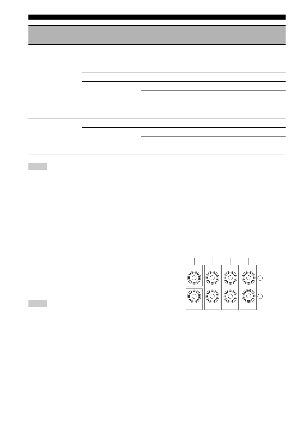
[1] [2]
CENTER
SUB
WOOFER
FRONT
[3] [4]
SURROUND
PRE OUT
[5]
[1] CENTER PRE OUT jack
Center channel output jack.
[2] FRONT PRE OUT jacks
Front channel output jacks.
[3] SURROUND PRE OUT jacks
Surround channel output jacks.
SINGLE(SB)
SUR.BACK/
PRESENCE
L
R
Page 27
Connections
MULTI CH INPUT
SUB
WOOFER
SUB
CENTER
FRONT(6CH)
SURROUND
SUR.BACK
(8CH)
TAPE
MD/
(C)
()
R
L
[4] SUR.BACK/PRESENCE PRE OUT jacks
Surround back or presence channel output jacks. When
you only connect one external amplifier for the surround
back channel, connect it to the SINGLE (SB) jack.
y
• To output surround back channel signals at these jacks, set
“Front Presence” to “None” and “Surround Back” to any
parameter except “None” (
page 93).
• To output presence channel signals at these jacks, set “Front
Presence” to “Yes” and “Surround Back” to “None” (
page 93).
[5] SUBWOOFER PRE OUT jack
Connect a subwoofer with a built-in amplifier.
■ Connecting a multi-format player or an
external decoder
This unit is equipped with 6 additional input jacks
(FRONT L/R, CENTER, SURROUND L/R and
SUBWOOFER) for discrete multi-channel input from a
multi-format player, external decoder, etc. If you set
“Input Channels” to “8ch” (page 91), the analog audio
input jacks assigned as “Front Input” can be used as the
front channel input jacks.
Notes
• When you select “MULTI CH” as the input source, the digital
sound field processor is automatically disabled.
• Since this unit does not redirect signals input at the MULTI CH
INPUT jacks to accommodate for missing speakers, connect at
least a 5.1-channel speaker system when using this feature.
*
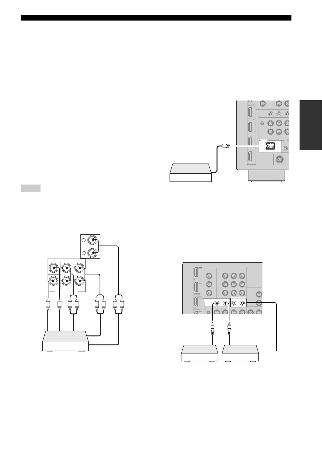
■ Connecting a Yamaha iPod universal
dock or Bluetooth wireless audio
receiver
This unit is equipped with the DOCK terminal on the rear
panel that allows you to connect a Yamaha iPod universal
dock (such as YDS-11, sold separately) or Bluetooth
wireless audio receiver (such as YBA-10, sold separately).
Connect a Yamaha iPod universal dock or Bluetooth
receiver to the DOCK terminal on the rear panel of this
unit using its dedicated cable.
PREPARATION
DOCK
Yamaha iPod universal dock or
Bluetooth wireless audio
receiver
■ Using REMOTE IN/OUT jacks
When the components are the Yamaha products and have
the capability of the transmission of the remote control
signals, connect the REMOTE IN and REMOTE OUT
jacks to the remote control input and output jack with the
monaural analog mini cable as follows.
Subwoofer out
Center out
LR
Front out (6ch)
Surround back
out (8ch)
Surround out
LRLR
Multi-format player/
External decoder
* The analog audio input jacks assigned as “Front Input” in
“MULTI CH” (
page 91).
IN 1 2
Front out (8ch)
REMOTE
Remote
control out
OUT IN OUT
Remote
control in
*
Infrared signal
receiver or
Yam ah a
component
* You can connect another set of infrared signal receiver and
Yamaha component to the REMOTE IN/OUT 2 jacks same as
the REMOTE IN/OUT 1 jacks.
Yamah a
component
(CD or DVD
player, etc.)
27 En
Page 28
Connections
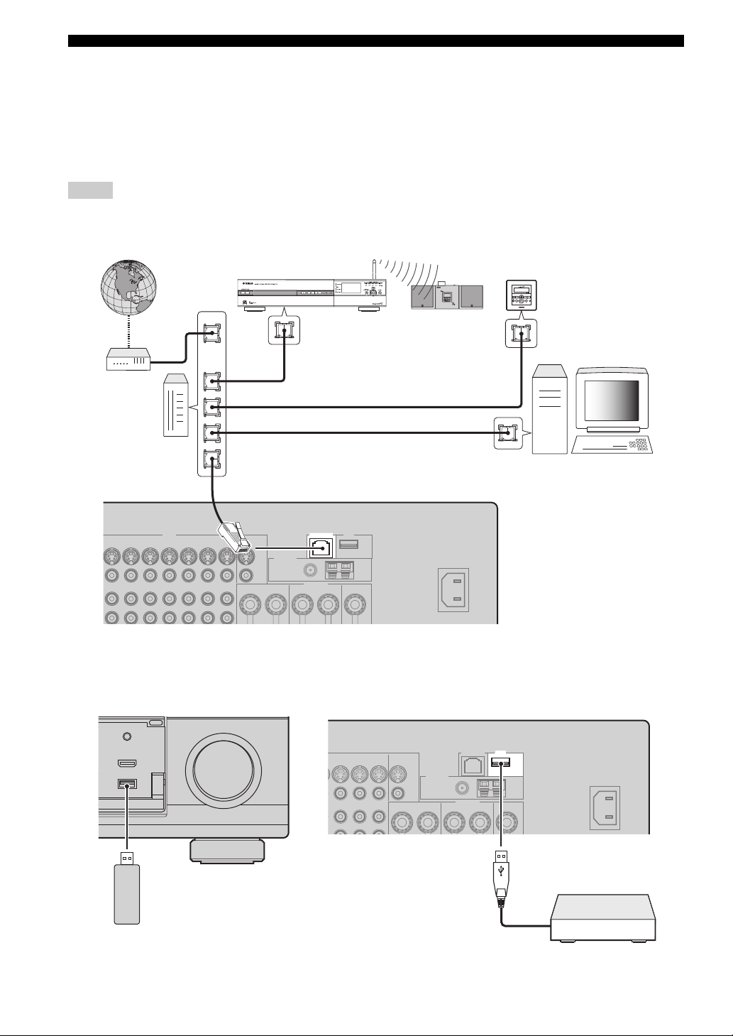
■ Connecting to the network
To connect this unit to your network, plug one end of a network cable (CAT-5 or higher straight cable) into the
NETWORK port of this unit, and plug the other end into one of the LAN ports on your router that supports the DHCP
(Dynamic Host Configuration Protocol) server function. The following diagram shows a connection example where this
unit is connected to one of the LAN ports on a 4-port router. To enjoy music files saved on your PC and Yamaha MCX2000, access the Internet Radio, or control this unit by using your PC, each device must be connected properly in the
network.
Notes
• You must use an STP (shielded twisted pair) cable (commercially available) to connect a network hub or router and this unit.
• If the DHCP server function on your router is disabled, you need to configure the network settings manually (
• Yamaha MCX-2000, MCX-A10 and MCX-C15 may not be for sale in some locations.
Internet
Yamaha MCX-2000
page 102).
Yamaha MCX-C15
WAN
Yamaha MCX-A10
(with optional
speakers)
LAN
PC
Modem
Router
Network cable
NETWORK
■ Connecting USB storage devices
Connect a USB memory device or USB portable audio player to the USB port on the front panel or rear panel of this unit.
Set “USB Select” to “Front” (default) or “Rear” to select the active USB port (
(Front panel) (Rear panel)
INFO
VIDEO AUX
HDMI IN
USB
VOLUME
page 77).
USB
USB memory device or USB
portable audio player
28 En
USB storage device
Page 29
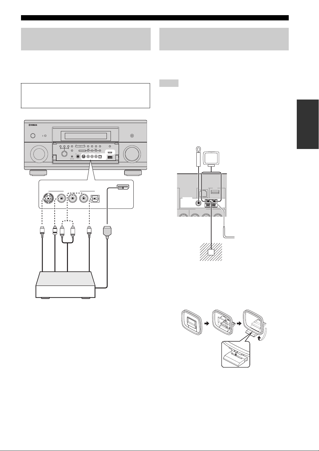
Connections
Using the VIDEO AUX jacks on the front panel
Use the VIDEO AUX jacks on the front panel to connect a
game console or a video camera to this unit. To reproduce
the source signals input at these jacks, select “V-AUX” as
the input source.
Caution
Be sure to turn down the volume of this unit and other
components before making connections.
MAIN ZONE
MASTER
ON
ON/OFF
OFF
AUDIO SELECT/
INPUT
S VIDEO
REC OUT
VIDEO
TONE
CONTROL
MENU ENTER
PROGRAM
VIDEO AUX
STRAIGHT
EFFECT
OPTIMIZER
MIC
YPAO
SILENT CINEMA
AUDIO
PHONES
PRESET/TUNING/CH
MULTI ZONE
SEARCH
STEREO/
MODE
MONO
MEMORY
CATEGORY INFO
BAND
ZONE ON/OFF
ZONE CONTROLS
VIDEO AUX
ZONE 3
AUDIO
OPTICAL
VIDEO AUX
ZONE 4
HDMI IN
USB
RL
OPTICAL
ZONE 2
S VIDEO
VIDEO
RL
PURE DIRECT
VOLUME
VIDEO AUX
HDMI IN
Connecting the FM and AM antennas
Both FM and AM indoor antennas are supplied with this
unit. In general, these antennas should provide sufficient
signal strength.
Notes
• The types of the supplied antennas and the FM antenna terminal
of this unit are different depending on the models.
• The AM loop antenna should be placed away from this unit.
• The AM loop antenna should always be connected, even if an
outdoor AM antenna is connected to this unit.
• If you experience poor reception quality, install an outdoor
antenna. Consult the nearest authorized Yamaha dealer or
service center about outdoor antennas.
Indoor FM
antenna
(supplied)
ANTENNA
75Ω UNBAL.
FM
GND
AM loop
antenna
(supplied)
AM
PREPARATION
V
S
L
S-Video output
Video output
Game console or
video camera
O
R
Optical output
Audio output
HDMI output
Outdoor AM antenna
Use a 5 to 10 m (16 to 33 ft)
vinyl-covered wire extended
outdoors from a window.
Ground (GND terminal)
For maximum safety and minimum
interference, connect the antenna GND
terminal to a good earth ground. A good
earth ground is a metal stake driven into
moist earth.
Assembling the supplied AM loop antenna
29 En
Page 30
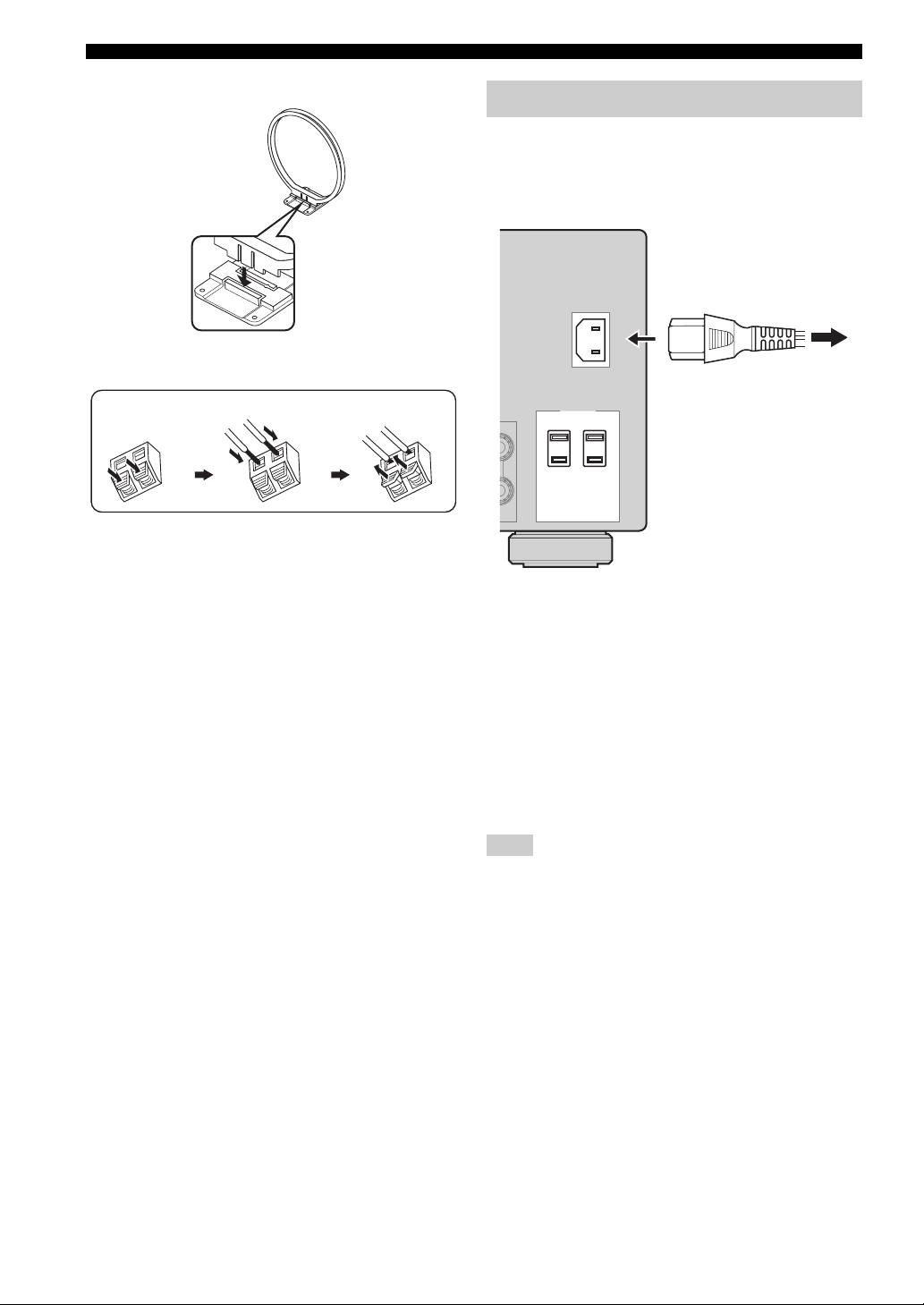
Connections
(U.S.A. model)
Connecting the power cable
■ Connecting the AC power cable
Plug the supplied AC power cable into the AC inlet after
all other connections are complete, then plug the AC
power cable into an AC wall outlet.
AC IN
Connecting the wire of the AM loop antenna
Press and hold
Insert
Release
y
The wire of the AM loop antenna does not have any polarity
and you can connect either end of the wire to AM or GND
terminal.
To the AC wall outlet
AC OUTLETS
SWITCHED
■ AC OUTLET(S) (SWITCHED)
U.S.A. and Australia models ................................. 1 outlet
Canada model ....................................................... 2 outlets
Use these outlet(s) to supply power to any connected
components. Connect the power cable of your other
components to these outlet(s). Power to these outlet(s) is
supplied when this unit is turned on. However, power to
these outlet(s) is cut off when this unit is turned off. For
information on the maximum power or the total power
consumption of the components that can be connected to
these outlet(s), see “Specifications” (page 154).
Note
The rated power of the component (such as a subwoofer)
connected to these outlet(s) cannot exceed the maximum power
supplied by this unit.
30 En
Page 31

Connections
Setting the speaker impedance and display language
Caution
If you are to use 6 ohm speakers, set “SPEAKER
IMP.” to “6Ω MIN” as follows BEFORE using this
unit. You can also use 4 ohm speakers as the front
speakers (page 130).
1 Make sure this unit is turned off.
2 Press and hold NSTRAIGHT on the front
panel and then press BMASTER ON/OFF
inward to the ON position.
This unit turns on, and the advanced setup menu
appears in the front panel display.
While holding
STRAIGHT
EFFECT
3 Rotate the
“SPEAKER IMP.”.
4 Press
“6Ω MIN”.
5 Rotate the
“LANGUAGE”.
6 Press
language setting for the GUI screen in the
video monitor.
Choices: ENGLISH (English),
M
N
STRAIGHT repeatedly to select
M
N
STRAIGHT to select desired
JAPANESE (Japanese), FRENCH (French),
GERMAN (German), SPANISH (Spanish),
RUSSIAN (Russian)
down
PROGRAM selector to select
PROGRAM selector to select
MASTER
Turning this unit on and off
■ Turning on this unit
Press BMASTER ON/OFF on the front panel
inward to the ON position.
When you turn on this unit by pressing BMASTER ON/
OFF, the main zone is turned on.
■ Turning off this unit
Press BMASTER ON/OFF on the front panel
again to release it outward to the OFF position.
■ Set the main zone to the standby mode
A
Press
(or
MAIN ZONE ON/OFF
D
STANDBY
).
■ Turning on the main zone from the
standby mode
Press AMAIN ZONE ON/OFF (or EPOWER).
y
• Basically, we recommend that you use the standby mode to turn
off this unit. In the standby mode, this unit consumes a small
amount of power in order to receive infrared signals from the
remote control.
• Even when this unit is in the standby mode, power consumption
increases if “Standby Through” (page 101) or “Network
Standby” (page 102) is on. If you do not use this unit for long
periods of time, turn off this unit by pressing BMASTER ON/
OFF to minimize power consumption.
• AMAIN ZONE ON/OFF, DSTANDBY and EPOWER are
operational only when BMASTER ON/OFF is pressed
inward to the ON position.
• When you turn on this unit, there will be a delay for a few
seconds before this unit can reproduce sound.
If there are some problems...
• First, turn off and then turn on this unit again.
• If problems persist, initialize the parameters of this
unit (page 147).
PREPARATION
Notes
• For details about the display language, see “Language”
(page 132)
• You can also select the display language with the GUI menu
(page 107).
7 Press
Note
The setting you made is reflected next time you turn on this
unit.
B
MASTER ON/OFF to release it
outward to the OFF position to save the new
setting and turn off this unit.
31 En
Page 32

Connections
t
q
Front panel display
b
ca d
R
SILENT
CINEMA
IN
OUT 1 OUT 2
ENHANCER
q
DIGITAL PLUS
q
PL x
q
TRUE HD
USB
NET
YPAO PRESET
VIRTUAL ADAPTIVE DRC
DISCRETE
q
EX
MASTER AUDIO
neural
CS
DSD
PCM
WMA
MP3
DOCK V-A UX VCR DVR CBL/SAT DVD BD/HD DVD MD/CD-R TV CD PHONO MULTI CH TUNER
3
MATRIX
96
HD
24
HD
TAG
TUNED STEREO
AUTO MEMORY
CATEGORY ALL
HOLD
ZONE2
SLEEP
ZONE3
PRE
ZONE4
AMP
XM SIRIUS
dB
VOLUME
L C R
SL LFE SR
SBL SB SBR
e
g
h
SILENT
CINEMA
IN
OUT 1 OUT 2
ENHANCER
q
DIGITAL PLUS
q
PL x
q
TRUE HD
YPAO PRESET
VIRTUAL ADAPTIVE DRC
DISCRETE
q
EX
MASTER AUDIO
HD
MATRIX
96
24
i
j
3
k
l
m
a CSII indicator (U.S.A. model only)
Lights up when the SRS Circle Surround II decoder is
active (page 53).
b neural indicator
(U.S.A. and Canada models only)
Lights up when the Neural-THX Surround decoder is
active (page 53).
c Headphones indicator
Lights up when headphones are connected (page 44).
d Input source indicators
The corresponding cursor lights up to show the currently
selected input source.
Notes
• The XM and SIRIUS indicators are only applicable to the
U.S.A. and Canada models.
• The R indicator on the right side of the USB indicator lights up
when “USB Select” is set to “Rear” (page 92).
• The NET indicator also lights up when “Network Standby”
(page 102) is set to “On” and this unit is in the standby mode.
e Input signal indicators
The respective indicator lights up when this unit is
reproducing DSD (Direct Stream Digital), PCM (Pulse
Code Modulation), WMA (Windows Media Audio) or,
MP3 (MPEG-1 Audio Layer-3) audio signals.
f Multi-information display
Shows the name of the current sound field program and
other information when adjusting or changing settings.
HD
TAG
f
n
o
p
TUNED STEREO
AUTO MEMORY
CATEGORY ALL
HOLD
ZONE2
SLEEP
ZONE3
PRE
ZONE4
AMP
dB
VOLUME
L C R
SL LFE SR
SBL SB SBR
r
s
g HDMI indicator
IN indicator
Lights up when the signal of the selected input source
is input at one of the HDMI input jacks (page 21).
OUT 1/OUT 2 indicator
The respective indicator lights up when the HDMI
signal is output at the HDMI OUT jacks. (page 21).
h ENHANCER indicator
Lights up when the Compressed Music Enhancer mode is
turned on (page 51).
i YPAO indicator
Lights up when you run the automatic setup and when the
speaker settings configured by the automatic setup are
used without any modifications (page 35).
j PRESET indicator
Lights up while this unit is in the preset tuning mode.
k DSP indicators
The respective indicator lights up when any of the sound
field programs are selected.
SILENT CINEMA indicator
Lights up when headphones are connected and a
sound field program is selected (page 51).
CINEMA DSP indicator
Lights up when you select a CINEMA DSP sound
field program (page 46).
3D indicator
Lights up when the CINEMA DSP 3D mode is turned
on (page 52).
VIRTUAL indicator
Lights up when Virtual CINEMA DSP is active (see
page 51).
32 En
Page 33

l ADAPTIVE DRC indicator
Lights up when the adaptive dynamic range control
feature is turned on (page 95).
m Decoder indicators
The respective indicator lights up when any of the
decoders of this unit function.
n Tuner indicators
Light up when this unit is in the FM, AM, XM Satellite
Radio, or SIRIUS Satellite Radio tuning mode.
Note
The HD and TAG indicators are only applicable to the U.S.A.
model and used when this unit is tuned into the HD Radio
reception band.
o Menu browsing indicator
Lights up if any items exist under the current item during
menu browsing for iPod, etc.
p SLEEP indicator
Lights up while the sleep timer is on (page 45).
q PRE AMP indicator
Lights up when this unit is in the pre-amplifier mode
(page 131).
r VOLUME level indicator
• Indicates the current volume level.
• Flashes while the mute function is on (page 44).
s Input channel and speaker indicators
Presence speaker indicators
L C R
SL LFE SR
Input channel indicators
SBL SB SBR
Input channel indicators
• Indicate the channel components of the current
digital input signal.
• Light up or flash according to the settings of the
speakers when this unit is in the automatic setup
procedure (page 35).
Presence speaker indicators
Light up according to setting for “Front Presence”
(page 93) in “Configuration” when this unit is in the
auto setup procedure (page 35) or the speaker level
setting procedure in the “Level” (page 94).
t ZONE2/ZONE3/ZONE4 indicators
Lights up when Zone 2, Zone 3, or Zone 4 is turned on
(page 127).
Connections
Using the remote control
The remote control transmits a directional infrared ray.
Be sure to aim the remote control directly at the remote
control sensor on this unit during operation.
Remote control sensor
MAIN ZONE
MASTER
ON
ON/OFF
OFF
INPUT
STRAIGHT TUNING MODE
MEMORY FM/AM
PRESET/TUNING
SPEAKERS
AB
AUDIO
SELECT
SILENT CINEMA
PHONES
EDIT
EFFECT DISPLAY
MAN'L/AUTO
CATEGORY
SEARCH MODE
ZONE
REC OUT/
ZONE ON/OFF
CONTROLS
ZONE 2
MULTI
ZONE
ZONE 2
ZONE 3 ZONE 4
OPTICAL
VIDEO
L
R
AUDIO
S VIDEO
YPAO
OPTIMIZER
MIC
VIDEO AUX
Approximately 6 m (20 ft)
6LIGHT
Lights up the remote control buttons and the display
window (4).
Display window (4)
[1] [2]
MAIN
ZONE 2
ZONE 3
ZONE 4
ID 2ID 1
[3] [4]
[1] ID1/ID2 indicator
Indicates the currently selected remote control ID
(page 130).
[2] Transmit indicator
Appears while the remote control is sending infrared
signals.
[3] Zone indicators
Indicates the currently controlling zone (page 127).
[4] Information display
Shows the name of the selected input source that you
can control.
Infrared window (1)
Outputs infrared control signals. Aim this window at the
component you want to operate.
PROGRAM
PUSH ENTER
HDMI IN USB
PURE DIRECT
VOLUME
MENU
TONE CONTROL
30 30
PREPARATION
33 En
Page 34

Connections
Operation mode selector (F)
The function of some buttons depends on the operation
mode selector position.
AMP
Operates the amplifier function of this unit.
SOURCE
Operates the component selected with an input
selector button (page 114).
TV
Operates the TV (page 113).
Notes
• Do not spill water or other liquids on the remote control.
• Do not drop the remote control.
• Do not leave or store the remote control in the following
conditions:
– places of high humidity, such as near a bath
– places of high temperatures, such as near a heater or stove
– places of extremely low temperatures
– dusty places
• To set the remote control codes for other components, see
page 116.
Opening and closing the front panel door
When you want to use the controls behind the front panel
door, open the door by gently pressing on the lower part of
the panel. Keep the door closed when not using these
controls.
34 En
Page 35

Optimizing the speaker setting for your listening room
This unit employs the YPAO (Yamaha Parametric room Acoustic Optimizer) technology which lets you avoid
troublesome listening-based speaker setup and achieves highly accurate sound adjustments automatically. The supplied
optimizer microphone collects and this unit analyzes the sound your speakers produce in your actual listening
environment.
This unit is equipped with various automatic setup features. You can select the automatic setup features according to your
preference.
Quick automatic setup (page 35)
Use this feature to carry out the automatic setup without using the GUI screen.
Basic automatic setup (page 36)
Use this feature to optimize the setup of this unit for one listening position. You can also select the parameters to be
optimized by the automatic setup.
Advanced automatic setup (page 38)
Use this feature to optimize the setup of this unit for multiple listening positions. You can also select the parameters to be
optimized by the automatic setup.
PREPARATION
Before starting the automatic setup
Make sure of the following check points before
starting the automatic setup operations.
❏ Speakers are connected appropriately.
❏ Headphones are disconnected from this unit.
❏ This unit is turned on.
❏ The connected subwoofer is turned on and the
volume level is set to about half way (or slightly
less).
❏ The crossover frequency controls of the
connected subwoofer is set to the maximum.
VOLUME
MIN
MAX
Controls of a subwoofer (example)
❏ The room is sufficiently quiet.
❏ Set the operation mode selector on the remote
control to FAMP.
Notes
• Be advised that it is normal for loud test tones to be output
during the automatic setup procedure.
• To achieve the best results, make sure the room is as quiet as
possible while the automatic setup procedure is in progress. If
there is too much ambient noise, the results may not be
satisfactory.
CROSSOVER
HIGH CUT
MIN MAX
Quick automatic setup
Use this feature to carry out the automatic setup without
using the GUI screen.
1 Connect the supplied optimizer microphone
to the OPTIMIZER MIC jack on the front
panel.
AUDIO SELECT/
REC OUT
CONTROL
MENU ENTER
PROGRAM
TONE
STRAIGHT
EFFECT
OPTIMIZER
MIC
YPAO
PRESET/TUNING/CH
MULTI ZONE
PHONES
SILENT CINEMA
The following screen appears in the front panel
display.
AUTO SETUP
ENTER TO START
Note
“View GUI Menu” appears if the GUI menu screen is
turned on. In this case, press IMENU to turn off the GUI
menu screen or follow
(page 36)
2 Place the optimizer microphone at your
normal listening position on a flat level
surface with the omni-directional
microphone heading upward.
SEARCH
STEREO/
MODE
MONO
S VIDEO
MEMORY
ZONE 2
VIDEO AUX
VIDEO
ZONE ON/OFF
ZONE 3
ZONE CONTROLS
ZONE 4
RL
AUDIO
CATEGORY INFO
BAND
OPTICAL
Omni-directional
microphone
“Basic automatic setup”
VIDEO AUX
HDMI IN
USB
35 En
Page 36

Optimizing the speaker setting for your listening room
Optimizer microphone
y
It is recommended that you use a tripod (etc.) to affix the
optimizer microphone at the same height as your ears
would be when you are seated in your listening position.
You can use the attached screw of a tripod (etc.) to fix the
optimizer microphone to the tripod (etc.).
Before proceeding next operation
Once you perform the next operation, this unit starts the
automatic setup procedure in 10 seconds. During the automatic
setup procedure, do not perform any operation on this unit. For
more accurate measurements, we recommended that you get out
of the room or move to the wall where speakers are not around
during the measurement. It takes approximately 3 minutes.
3 Press 9ENTER to start the measurement.
This unit starts to count down from 10 seconds.
y
• To start the measurement immediately, press 9ENTER
again.
• To cancel the automatic setup and return to the previous
screen, press ?RETURN and then 9ENTER.
Basic automatic setup
Use this feature to optimize the setup of this unit for one
listening position. You can also select the parameters to be
optimized in the automatic setup.
1 Turn on the video monitor and then follow
steps 1 and 2 in “Quick automatic setup”
(page 35).
2 Press IMENU on the remote control.
The following screen (GUI menu) appears in the
video monitor.
Information
Setup Menu
Start
3 To select the parameters to be optimized,
press 9k to select “Setup Menu” and then
press 9h.
When you do not need to select the parameters to be
optimized, skip to step 6.
y
If you do not select the parameters to be optimized, this
unit will optimize the parameters you selected last time.
All the parameters except “Angle” are selected by the
initial factory settings.
NOTICE
Loud test tones are
output.
Please keep quiet
or leave the room.
Start:ENTER
Loud test tones are output from each speaker during
the measurement. Once all items are measured,
“COMPLETED” appears.
COMPLETED
PLS UNPLUG MIC
Note
If an error or warning message appears, see “Automatic
setup” (page 145).
ERROR: E-01
PRESS ENTER
4 Disconnect the optimizer microphone to
complete the automatic setup.
y
You can check the results of the measurements by using
the GUI screen (page 40).
36 En
4 Press 9k / n repeatedly to select the
parameter and then press 9ENTER to
check or uncheck the box.
Check the boxes for the parameters to be optimized.
Parameter Descriptions
Multi Measure
(Multiple point
measurement)
Wiring
(Speaker wiring)
Distance
(Speaker distance)
Size
(Speaker size)
You can optimize the setup of this unit for
multiple listening positions. For details, see
“Advanced automatic setup” (page 38). In
the basic automatic setup, leave this setting
to the default.
This unit checks and adjusts which speakers
are connected and the polarity of each
speaker.
This unit checks and adjusts the distance of
each speaker from the listening position and
adjusts the timing of each channel.
This unit checks and adjusts the frequency
response of each speaker and sets the
appropriate low-frequency crossover for
each channel.
Page 37

Optimizing the speaker setting for your listening room
Parameter Descriptions
Equalizing
(Speaker
equalizing)
Parametric equalizer adjusts the level of the
specified frequency bands. This unit
automatically selects the crucial frequency
bands for the listening room and adjusts the
level of the selected frequency bands to
create a cohesive sound field in the room.
Level
(Speaker level)
Angle
(Speaker angle)
This unit checks and adjusts the volume
level of each speaker.
Checks the angles of the front speakers,
surround speakers, and front presence
speakers.
5 If you have finished the settings, press 9l
to return to the previous menu level and then
press 9n to select “Start”.
Before proceeding next operation
Once you perform the next operation, this unit starts the
automatic setup procedure in 10 seconds. During the
automatic setup procedure, do not perform any operation on
this unit. For more accurate measurements, we recommended
that you get out of the room or move to the wall where
speakers are not around during the measurement. It takes
approximately 3 minutes.
6 Press 9ENTER to start the measurement.
This unit starts to count down from 10 seconds.
y
• To start the measurement immediately, press 9ENTER
again.
• To cancel the automatic setup and return to the previous
screen, press ?RETURN and then 9ENTER.
Loud test tones are output from each speaker during
the measurement.
If you have selected “Angle” in step 4, the following
screen appears. Proceed to step 7.
Equalizing
Level
Angle Check
Angle
Result
Put the microphone at
1st listening position
Next:ENTER
1
2
3
Note
If an error or warning message appears, see “Error and
warning messages” (page 38).
Retry
Exit Detail
Pre Check
Main Check
Wiring
E09:User Cancel
7 Place the supplied microphone base at the
position you will be seated most frequently.
Make sure that the arrow on the microphone base
points the center speaker or about the midpoint
between the front left and right speakers.
Microphone base
FRONT
DIRECTION
Note
It is recommended that you use a tripod (etc.) to affix the
microphone base at the same height as your ears would be
when you are seated in your listening position. You can
use the attached screw of a tripod (etc.) to fix the
microphone base to the tripod (etc.).
8 Place the optimizer microphone to the
position “1” on the microphone base and
then press 9ENTER.
PREPARATION
If you have not selected “Angle” in step 4,
“Measurement Completed Successful” appears once
all items are measured. Skip to step 11.
Angle Check
Angle
Result
Measurement Completed
Successful
Detail:
[ ]
Exit:ENTER
This unit starts the measurement of the speaker
angles.
9 Move the optimizer microphone to the
position “2”on the microphone base and
then press 9ENTER.
37 En
Page 38

Optimizing the speaker setting for your listening room
10 Move the optimizer microphone to the
position “3”on the microphone base and
then press 9ENTER.
“Measurement Completed Successful” appears once
all items are measured.
11 Press 9 ENTER to exit from the “Result”
screen.
y
To view the measurement results in detail, press 9h.
Press 9k / n repeatedly to toggle between parameters
(page 36). Press 9l to return to the “Result” screen.
12 Press 9 l to select “Yes” to save the
measurement results or 9h to select “No”
to discard them.
13 Press I MENU to turn off the GUI menu and
disconnect the optimizer microphone.
■ Error and warning messages
If an error or warning message appears during the
automatic setup procedure, carry out one of the following
operations. For details on each message, see “Automatic
setup” (page 145).
• To view the details on the error and warning messages,
press 9h. Press 9k / n to display the previous/next
page (if available). Press 9l to return to the previous
menu level.
• To return to the GUI menu, press 9l.
• To retry the measurement, press 9k.
• To ignore the message and continue the process, press
9n.
Note
Some operations cannot be performed depending on the type of
error (or warning).
Advanced automatic setup
Use this feature to optimize the setup of this unit for
multiple listening positions. You can also select the
parameters to be optimized by the automatic setup.
1 Turn on the video monitor and then connect
the optimizer microphone to the OPTIMIZER
MIC jack on the front panel.
2 Place the optimizer microphone at the first
listening position.
The following illustration shows how to place the
optimizer microphone in order to optimize the setup
of this unit for seven listening positions for example.
1 7
2 6
43 5
/2/3/4/5/6/7: Listening positions
1
3 Press IMENU on the remote control.
The GUI menu appears in the video monitor.
4 Press 9k to select “Setup Menu” and then
press 9h.
5 Press 9k / n repeatedly to select “Multi
Measure” and then press 9h.
38 En
Information
Setup Menu
Start
Multi Measure 1
Wiring
Distance
Page 39

Optimizing the speaker setting for your listening room
6 Press 9k / n repeatedly to set the number of
listening positions and press 9l.
Choices: 1 (default), 2, 3, 4, 5, 6, 7, 8
Information
Setup Menu
Start
Multi Measure 7
Wiring
Distance
7 To select the parameters to be optimized,
press 9k / n to select the parameter and
then press 9ENTER to check or uncheck
the box.
When you do not need to select the parameters to be
optimized, skip to step 8.
y
If you do not select the parameters to be optimized, this
unit will optimize the parameters you selected last time.
All the parameters except “Angle” are selected by the
initial factory settings.
8 Press 9l to return to the previous menu
level and then press 9n to select “Start”.
Note
If an error or warning message appears, see “Error and
warning messages” (page 38).
10 Move the optimizer microphone to the
second listening position and then press
9ENTER to start the measurement.
y
To skip the measurements at the remaining listening
positions, press 9n.
11 Repeat step 10 until the measurement at all
listening positions are made.
If you have selected “Angle” in step 7, follow steps 7
to 13 in “Basic automatic setup” (page 36).
If you have not selected “Angle” in step 7,
“Measurement Completed Successful” appears once
all items are measured. Follow steps 11 to 13 in
“Basic automatic setup” (page 36).
PREPARATION
Before proceeding next operation
Once you perform the next operation, this unit starts the
automatic setup procedure in 10 seconds. During the
automatic setup procedure, do not perform any operation on
this unit. For more accurate measurements, we recommended
that you get out of the room or move to the wall where
speakers are not around during the measurement.
9 Press 9ENTER to start the measurement.
This unit starts to count down from 10 seconds.
y
• To start the measurement immediately, press 9ENTER
again.
• To cancel the automatic setup and return to the previous
screen, press ?RETURN and then 9ENTER.
Loud test tones are output from each speaker during
the measurement. Once all items for the first listening
position are measured, the following message
appears.
Pre Check
Main Check
Wiring
Distance
Put the microphone at
2nd listening position
Next:ENTER
Skip:
[ ]
39 En
Page 40

Optimizing the speaker setting for your listening room
Reviewing and reloading the automatic setup parameters
Use this feature to review the result of the automatic setup.
You can also reload the automatic setup parameters in case
you are not satisfied with the speaker setup and sound
adjustments you have configured manually.
Note
If you reload the automatic setup parameters, the settings you
have configured manually are cleared. To save the settings
before reloading the automatic setup parameters, see “System
Memory” (page 108).
1 Set the operation mode selector to FAMP
and then press IMENU.
The GUI menu appears in the video monitor.
y
If the menu directory other than “Top Menu” (page 84) is
displayed, press and hold IMENU to display the top GUI
menu.
2 Press 9k / n repeatedly to select “Setup”
and then press 9h.
3 Press 9k / n repeatedly to select “Auto
Setup” and then press 9h.
4 Press 9k to select “Information” and then
press 9h.
5 Press 9k / n repeatedly to select the
parameter of which you want to check the
setting.
Parameter Descriptions
Multi Measure
(Multiple point
measurement)
Wiring
(Speaker wiring)
Distance
(Speaker
distance)
Size
(Speaker size)
Equalizing
(Speaker
equalizing)
Level
(Speaker level)
Angle
(Speaker angle)
Displays the number of listening position
actually measured.
Displays the polarity of each connected
speaker.
– “NRM” appears when the polarity of the
connected speaker is normal.
– “REV” appears when the polarity of the
connected speaker is reversed.
– “DET” appears when this unit detects the
subwoofer is connected.
– “–– –” appears when no speaker is
connected to the corresponding speaker
channel.
Displays the speaker distance from the
listening position. Press 9 h repeatedly to
switch the unit to display the value of the
each speaker distance.
Displays the size of the connected speakers
and the bass cross over frequency (“Cross”).
– “LRG” appears when the connected
speaker has the ability to reproduce the
low-frequency signals effectively.
– “SML” appears when the connected
speaker does not have the ability to
reproduce the low-frequency signals
effectively.
Displays the result of the adjustment of the
frequency responses of each connected
speaker. You can switch the parametric
equalizer type that appears in the result
display by pressing 9h repeatedly in the
“Equalizing” result display. To apply the
result that is displayed in the display, press
9ENTER.
Choices: Natural, Flat, Front
– Select “Natural” to average out the
frequency response of all speakers with
higher frequencies being less
emphasized. Recommended if the “Flat”
setting sounds a little harsh.
– Select “Flat” to average the frequency
response of all speakers. Recommended
if all of your speakers are of similar
quality.
– Select “Front” to adjust the frequency
response of each speaker in accordance
with the sound of your front speakers.
Recommended if your front speakers are
of much higher quality than your other
speakers.
Displays the result of the adjustment of each
connected speaker output level. You can
display the result of the adjustment of the
speaker level for each parametric equalizer
type (see above) by pressing 9h
repeatedly. Select “Through” to display the
result when this unit does not use the
parametric equalizer.
Displays the angles of the front speakers,
surround speakers, and front presence
speakers.
40 En
Page 41

y
The results of the measurement that are the causes of the
warning message(s) appear in yellow or pink.
Notes
• “–––” appears when no speaker is connected to the
corresponding speaker channel or this unit does not measure the
corresponding speaker channel yet.
• If you change speakers, speaker positions, or the layout of your
listening environment, run the automatic setup again to
recalibrate your system.
• The distances displayed in the “Distance” results may be longer
than the actual distance depending on the characteristics of your
subwoofer or external amplifiers if you connect them.
• In the “Equalizing” results, different values may be set for the
same band to provide finer adjustments.
6 To reload the displayed parameter, press
9ENTER.
7 Press IMENU to turn off the GUI menu.
y
• You can also set the parametric equalizer type with “PEQ
Select” (page 96).
• You can set the phase of the connected subwoofer with “Phase”
(page 93).
Optimizing the speaker setting for your listening room
PREPARATION
41 En
Page 42

Playback
Caution
Extreme caution should be exercised when you play
back CDs encoded in DTS. If you play back a CD
encoded in DTS on a DTS-incompatible CD player,
you will only hear some unwanted noise that may
damage your speakers. Check whether your CD player
supports CDs encoded in DTS. Also, check the sound
output level of your CD player before you play back a
CD encoded in DTS.
y
To play DTS-encoded CDs when using a digital audio
connection, set “Decoder Mode” in “Input Select” to “DTS”
before the playback (page 90).
Before performing the following operations, set the operation
mode selector on the remote control to FAMP.
Basic procedure
1 Turn on the video monitor connected to this
unit.
y
• If you connect two video monitors to the HDMI OUT
jacks of this unit, press RHDMI OUT repeatedly to select
the active video monitor(s). See page 43 for details.
• You can operate this unit by using the graphical user
interface (GUI) screen (page 81).
• You can configure the display settings with “Video”
(page 99) and “Display Set” (page 105).
3 Start playback on the selected source
component or select a broadcast station.
• Refer to the instruction manuals for the source
component.
• FM/AM radio tuning (page 56)
• XM Satellite Radio tuning (page 61)
• SIRIUS Satellite Radio tuning (page 65)
• Bluetooth component playback (page 71)
• iPod playback (page 73)
• Playback via USB or network (page 75)
4
Rotate PVOLUME
to adjust the volume to the desired output
level.
y
To adjust the level of each speaker, see page 55.
5 Rotate the
M
one of the sound field program selector
buttons (Q) repeatedly) to select the desired
sound field program.
For details about sound field program, see page 46.
Selected sound field program category
Selected sound field program
(or press JVOLUME + /–
PROGRAM selector (or press
Movie
Sci-Fi
)
2 Rotate the
L
INPUT selector (or press one
of the input selector buttons (3))
The name of the selected input source appears for a
few seconds.
Available input sources
DOCK V-AUX VCR DVR CBL/SAT DVD BD/HD DVD MD/CD-R TV CD PHONO MULTI CH TUNER XM SIRIUS
USB
NET
DVD
Selected input source
42 En
y
To switch the information (current input source, current
sound field program, etc) displayed in the front panel
display, press JINFO (or set the operation mode selector
to FAMP and then press CINFO) repeatedly.
Page 43

Playback
Selecting audio input jacks (AUDIO SELECT)
Use this feature (audio input jack select) to switch the
input jack assigned to an input source when more than one
jacks are assigned to an input source.
1 Rotate the
of the input selector buttons (3)) to select
the desired input source.
2
Press CAUDIO SELECT
M
PROGRAM
mode to
SEL
input jack select setting.
USB
NET
L
INPUT selector (or press one
and then rotate
selector (or set the operation
FAMP
and then press
OAUDIO
repeatedly) to select the desired audio
Available input sources
DOCK V-AUX VCR DVR CBL/SAT DVD BD/HD DVD MD/CD-R TV CD PHONO MULTI CH TUNER XM SIRIUS
A.SEL: AUTO
Selected audio input jack
select setting
Selecting the multi-channel input component
Use this feature to select the component connected to the
MULTI CH INPUT jacks (page 27) as the input source.
Rotate the LINPUT selector on the front panel
to select “MULTI CH” (or press 3MULTI).
y
You can configure the multi channel input settings with
“MULTI CH” (page 90).
Note
Sound field programs cannot be selected when “MULTI CH” is
selected as the input source.
Selecting the HDMI OUT jack
Use this feature to select the HDMI OUT jack(s) to output
the input signals.
Set the operation mode selector to FAMP and
then press RHDMI OUT on the remote control
repeatedly to select the desired setting.
The HDMI output setting changes as follows.
OPERATION
BASIC
AUTO
HDMI
COAX/OPT
ANALOG
Automatically selects input signals in the
following order:
(1) HDMI
(2) Digital signals
(3) Analog signals
Selects only HDMI signals. When HDMI
signals are not input, no sound is output.
Automatically selects input signals in the
following order:
(1) Digital signals input at the COAXIAL jack.
(2) Digital signals input at the OPTICAL jack.
When no signals are input, no sound is output.
Selects only analog signals. If no analog
signals are input, no sound is output.
y
You can configure the default audio input jack select setting
with “Audio Select” (page 90).
Note
This feature is not available if no digital input jack is assigned
to the selected input source in “I/O Assignment” (page 105).
“HDMI” is available only when an HDMI input jack is
assigned.
OUT1+2 OUT1
OUT2OFF
OUT 1+2
OUT 1
OUT 2
OFF
Outputs the signals at both the HDMI OUT 1
and HDMI OUT 2 jacks simultaneously.
Outputs the signals at the HDMI OUT 1 jack.
Outputs the signals at the HDMI OUT 2 jack.
Does not output any signals at the HDMI OUT
1 and HDMI OUT 2 jacks. Select this setting
when you do not use the video monitor
connected to one of the HDMI OUT jacks.
y
You can select the HDMI OUT jack at which HDMI control
signals are output with “Control Monitor” (page 102).
43 En
Page 44

Playback
Using your headphones
Connect a pair of headphones with a stereo
analog audio cable plug to the PHONES jack on
the front panel.
MAIN ZONE
MASTER
ON
ON/OFF
OFF
AUDIO SELECT/
INPUT
REC OUT
MENU ENTER
PROGRAM
TONE
CONTROL
STRAIGHT
EFFECT
OPTIMIZER
MIC
YPAO
SEARCH
STEREO/
PRESET/TUNING/CH
MODE
MONO
MEMORY
CATEGORY INFO
BAND
ZONE ON/OFF
ZONE CONTROLS
MULTI ZONE
ZONE 2
PHONES
SILENT CINEMA
S VIDEO
VIDEO
VIDEO AUX
VIDEO AUX
ZONE 3
ZONE 4
HDMI IN
USB
RL
OPTICAL
AUDIO
PURE DIRECT
VOLUME
y
When you select a sound field program, SILENT CINEMA
mode activates automatically (page 51).
Notes
• When you connect headphones, no signals are output at the
speaker terminals.
• All digital multi-channel audio signals are mixed down to the
left and right headphone channels.
• When “MULTI CH” is selected as the input source, only the
signals input at the MULTI CH INPUT FRONT jacks are
output.
Muting the audio output
Press LMUTE on the remote control to mute the
audio output. Press LMUTE again to resume
the audio output.
y
• The VOLUME level indicator flashes while the mute function is
on.
• You can configure the muting level with “Muting Type”
(page 95).
Displaying the input source information
You can display the format, sampling frequency, channel,
bit rate and flag data of the current input signal.
1 Set the operation mode selector to FAMP
and then press 8STATUS on the remote
control.
The input source information screen appears in the
GUI screen.
2 Press 9l / h to toggle between the audio
and video information.
3 Press 8STATUS on the remote control
again to exit from the input source
information screen.
■ Audio information
Format Signal format. When this unit cannot detect a
digital signal, it automatically switches to
analog input.
Sampling The number of samples per second taken from
a continuous signal to make a discrete signal.
Channel The number of source channels in the input
signal (front/surround/LFE). For example, a
multi-channel soundtrack with 3 front
channels, 2 surround channels and LFE, is
displayed as “3/2/0.1”.
Bitrate The number of bits passing a given point per
second.
Dialogue The dialogue normalization level preset to the
current input bitstream signal.
Flag1/Flag2 Flag data encoded in the bitstream, or PCM
signals that cue this unit to automatically
switch decoders.
Notes
• “–––” appears when this unit cannot display the corresponding
information.
• Some high definition audio bitstream contents may not include
the discrete surround back left and right channel signals but are
encoded at the bitrate of 192 kHz.
• Even if you make settings to output bitstreams directly, some
players convert the Dolby TrueHD or Dolby Digital Plus
bitstreams to the Dolby Digital bitstreams, while converting the
DTS-HD Master Audio or DTS-HD High Resolution Audio
bitstreams to the DTS bitstreams.
44 En
Page 45

■ Video information
HDMI signal Type of the source video signals and
HDMI Resolution Resolution of the input signal (analog
Analog Resolution Resolution of the source video signals
HDMI Error Error message for HDMI sources or
HDMI error message
Device Over The number of the connected HDMI
HDCP Error
(HDMI Message)
Out Of Resolution Out of resolution. The connected
the video signals output at the HDMI
OUT jacks of this unit.
or HDMI) and the output signal
(HDMI).
and the analog video signals output at
the COMPONENT MONITOR OUT
jacks of this unit.
connected HDMI devices.
components is over the limit.
HDCP authentication failed.
monitor is not compatible with the
resolution of the input video signal.
Playback
Using the sleep timer
Use this feature to automatically set the main zone to the
standby mode after a certain amount of time. The sleep
timer is useful when you are going to sleep while this unit
is playing or recording a source. The sleep timer also
automatically turns off any external components
connected to the AC OUTLET(S) (page 30).
Set the operation mode selector to FAMP and
then press CSLEEP on the remote control
repeatedly to set the amount of time.
The sleep timer setting changes as shown below.
120min. 90min.
60min.30min.OFF
Once the sleep timer is set, the SLEEP indicator lights up
in the front panel display, and the display returns to the
selected sound field program.
To cancel the sleep timer
Set the operation mode selector to FAMP and then press
CSLEEP on the remote control repeatedly to select
“SLEEP OFF”.
y
If you set the main zone to the standby mode, the sleep timer is
automatically canceled.
OPERATION
BASIC
45 En
Page 46

Sound field programs
This unit is equipped with a variety of precise digital decoders that allow you to enjoy multi-channel playback from
almost any stereo or multi-channel sound source. This unit is also equipped with a Yamaha digital sound field processing
(DSP) chip containing several sound field programs which you can use to enhance your playback experience.
y
The Yamaha CINEMA DSP sound field programs are compatible with all Dolby Digital, DTS, Dolby Surround, Dolby TrueHD and
DTS-HD Master Audio sources.
Selecting sound field programs
Rotate the MPROGRAM selector (or set the
operation mode selector to FAMP and then
press one of the sound field selector buttons (Q)
repeatedly).
The name of the selected sound field program appears in
the front panel display and in the short message display.
y
• You can select the desired sound field program and setting the
parameters by using the GUI menu (page 85).
• Available sound field parameters and the created sound field
differ depending on the input sources and the settings of this
unit.
Notes
• When you select an input source, this unit automatically selects
the last sound field program used with the corresponding input
source.
• Sound field programs cannot be selected when the component
connected to the MULTI CH INPUT jacks is selected as the
input source (page 43) or when this unit is in the PURE
DIRECT mode (page 54).
• When you play back DTS 96/24 sources with any sound field
program, this unit applies the selected program without
activating the DTS 96/24 decoder.
• Sampling frequencies higher than 48 kHz are sampled down to
48 kHz or lower and then sound field programs are applied.
46 En
Page 47

Descriptions of the characteristics of the sound field programs
Following indexes indicates the characteristics and trends of each sound field program.
Note
The characteristics of the sound field programs may differ depending on the settings of the listening room, etc.
Sound field programs
Size of sound field space (Size)
Small Large
Indicates the size of the sound field to be generated. If the
value for this item is small, the sound is that of a small
space, while if the value is large, the sound is that of a vast
space.
Vertical/horizontal balance (V/H balance)
Vertical Horizontal
Indicates the balance of the vertical (height) and horizontal
directions for the sound field to be generated. If this item is
more in the horizontal direction, the sound is that of a
space with strong reflections from the walls, while if it is
more in the vertical direction, the sound is that of a space
with strong reflections from the ceiling.
Front/rear balance (F/R balance)
Front Rear
A CINEMA DSP sound field processing expressing
whether the effect is stronger towards the front or rear.
When the effect is stronger towards the front, the listener
senses a feeling of openness and depth towards the screen,
while when the effect is stronger towards the rear, the
listener gets a sense of envelopment and movement. Suits
basically all types of contents for programs with a good
front/rear balance, and is effective when selected
appropriately for programs in which the balance is more
towards either the front or rear.
Sound field atmosphere (Atmosphere)
Simple Complex
The sound field to be generated is evaluated according to
whether it is nearer to one or the other of the following;
Simple: Sounds that fade straight-forwardly, with a light,
gentle impression, depending on the program. This suits
almost all contents relatively well, but provides little
brilliance or powerfulness.
Complex: Sounds transform in complex ways as they fade
out, with a rich, brilliant impression, depending on the
program.
This is extremely effective for the right contents, but is
suited for a smaller range of contents.
Calm Powerful
The sound field to be generated is evaluated according to
whether it is nearer to one or the other of the following;
Calm: An overall composed, moderate effect, stressing the
overall quality of the atmosphere without aiming at any
extreme effects. This suits almost all contents relatively
well, but provides little showiness or powerfulness.
Powerful: Designed with specific contents in mind
(expressing vast spaces, feverish excitement, etc.). This is
extremely effective for the right contents, but is suited for a
smaller range of contents.
OPERATION
BASIC
■ For audio music sources
y
For audio music sources, we also recommend using the PURE DIRECT mode (page 54), STRAIGHT mode (page 52), or surround
decode mode (page 53).
CLASSICAL
1
CLASSICAL
Hall in Munich
This sound field simulates a concert hall with approximately 2500
seats in Munich, using stylish wood for the interior finishing as
normal standards for European concert halls. Fine, beautiful
reverberations spread richly, creating a calming atmosphere. The
listener’s virtual seat is at the center left of the arena.
Hall in Vienna
This is an approximately 1700-seated, middle-sized concert hall
with a shoebox shape that is traditional in Vienna. Pillars and
ornate carvings create extremely complex reflections from all
around the audience, producing a very full, rich sound.
Size
V/H balance
Atmosphere
Size
V/H balance
Atmosphere
Small
Vertical
Simple
Small
Vertical
Simple
Large
Horizontal
Complex
Large
Horizontal
Complex
47 En
Page 48

Sound field programs
Hall in Amsterdam
The large, shoe box shaped hall seats about 2200 around the circle
stage. Reflections are rich and pleasing while the sound travels
freely.
Church in Freiburg
Located in the south of Germany, this grand, stone-built church
has a pointed tower at 120 meters in height. Its long and narrow
shape and the high ceiling enable the elongated reverberation time
and limited initial reflection time. Thus, the rich reverberation
rather than the sound itself reproduces the atmosphere of the
church.
Chamber
This program creates a relatively wide space with a high ceiling
like an audience hall in a palace. It offers pleasant reverberations
that are suitable for courtly music and chamber music.
LIVE/CLUB
2
LIVE/CLUB
Village Vanguard
The Jazz club is on 7th Avenue, New York. This small club with
the low ceiling makes the powerful reflections converge toward the
stage located in the corner.
Size
V/H balance
Atmosphere
Size
V/H balance
Atmosphere
Size
V/H balance
Atmosphere
Size
V/H balance
Atmosphere
Small
Vertical
Simple
Small
Vertical
Simple
Small
Vertical
Simple
Small
Vertical
Simple
Large
Horizontal
Complex
Large
Horizontal
Complex
Large
Horizontal
Complex
Large
Horizontal
Complex
Warehouse Loft
The warehouse resembles some lofts in Soho. Sound reflects off
the concrete walls clearly with a lot of energy.
Cellar Club
This program simulates a live house with a low ceiling and homey
atmosphere. A realistic, live sound field features powerful sound
as if the listener is in a row in front of a small stage.
The Roxy Theatre
This is the sound field of a rock music live house in Los Angeles,
with approximately 460 seats. The listener’s virtual seat is at the
center left of the hall.
The Bottom Line
This is the sound field at stage front in The Bottom Line, that was
a famous New York jazz club once. The floor can seat 300 people
to the left and right in a sound field offering real and vibrant
sound.
Size
V/H balance
Atmosphere
Size
V/H balance
Atmosphere
Size
V/H balance
Atmosphere
Size
V/H balance
Atmosphere
Small
Vertical
Simple
Small
Vertical
Simple
Small
Vertical
Simple
Small
Vertical
Simple
Large
Horizontal
Complex
Large
Horizontal
Complex
Large
Horizontal
Complex
Large
Horizontal
Complex
48 En
Page 49

■ For various sources
ENTERTAIN
3
ENTERTAIN
Sound field programs
Sports
This program allows the listeners to enjoy stereo sport broadcasts
and studio variety programs with enriched live feeling. In sports
broadcasts, the voices of the commentator and sportscaster are
positioned clearly on the center while the atmosphere of the
stadium expands in an optimum space to offer the listeners with a
feeling of presence in the stadium.
■ For game programs
ENTERTAIN
3
ENTERTAIN
Action Game
This sound field is suitable for action games such as car racing and
FPS games. It uses the reflection data that limits the effects range
per channel in order to offer a powerful playing environment with
a being-there feeling by enhancing various effects tones while
maintaining a clear sense of directions.
Roleplaying Game
This sound field is suitable for role-playing and adventure games.
It combines the sound field effects for movies and the sound field
design used with “Action Game” to represent the depth and spatial
feeling of the field during play, while offering movie-like surround
effects in the movie scenes in the game.
■ For visual sources of music
ENTERTAIN
3
ENTERTAIN
Size
V/H balance
F/R balance
Atmosphere
Size
V/H balance
F/R balance
Atmosphere
Size
V/H balance
F/R balance
Atmosphere
Small
Vertical
Front
Calm
Small
Vertical
Front
Calm
Small
Vertical
Front
Calm
Large
Horizontal
Rear
Powerful
Large
Horizontal
Rear
Powerful
Large
Horizontal
Rear
Powerful
OPERATION
BASIC
Music Video
This sound field offers an image of a concert hall for live
performance of pop, rock and jazz music. The listener can indulge
oneself in a hot live space thanks to the presence sound field that
emphasizes the vividness of vocals and solo play and the beat of
rhythm instruments, and to the surround sound field that
reproduces the space of a big live hall.
Recital/Opera
This program controls the amount of reverberations at an optimum
level and emphasizes the depth and clarity of human voices.
“Recital/Opera” offers the reverberations of an orchestra box in
front of the listener at the same time as providing the acoustic
positioning and feeling of presence on the stage. The surround
sound field is relatively moderate, but the data for concert hall
effects are used to represent the inherent beauty of music. The
listener will not be fatigued even after long hours of opera
entertainment.
Size
V/H balance
F/R balance
Atmosphere
Size
V/H balance
F/R balance
Atmosphere
Small
Vertical
Front
Calm
Small
Vertical
Front
Calm
Large
Horizontal
Rear
Powerful
Large
Horizontal
Rear
Powerful
49 En
Page 50

Sound field programs
■ For movie sources
y
You can select the desired decoder (page 53) used with following sound field program (except “Mono Movie”).
MOVIE
4
MOVIE
Standard
This program create a sound field emphasizing the surrounding
feeling without disturbing the original acoustic positioning of
multi-channel audio such as Dolby Digital and DTS. It has been
designed with the concept of “an ideal movie theater”, in which
the audience is surrounded by beautiful reverberations from the
left, right and rear.
Spectacle
This program represents the spectacular feeling of large-scale
movie productions. It reproduces a broad theater sound field
matching the cinemascope and wider-screen movies with an
excellent dynamic range from very small to extremely large sound.
Sci-Fi
This program clearly reproduces the finely elaborated sound
design of the latest science fiction and special effects-featuring
movies. You can enjoy a variety of cinematographically created
virtual spaces reproduced with clear separation between dialog,
sound effects and background music.
Adventure
This program is ideal for precisely reproducing the sound design
of action and adventure movies. The sound field restrains
reverberations but puts emphasis on reproducing a powerful space
expanded widely to the left and right. The reproduced depth is also
restrained relatively to ensure the separation between audio
channels and the clarity of the sound.
Size
V/H balance
F/R balance
Atmosphere
Size
V/H balance
F/R balance
Atmosphere
Size
V/H balance
F/R balance
Atmosphere
Size
V/H balance
F/R balance
Atmosphere
Small
Vertical
Front
Calm
Small
Vertical
Front
Calm
Small
Vertical
Front
Calm
Small
Vertical
Front
Calm
Large
Horizontal
Rear
Powerful
Large
Horizontal
Rear
Powerful
Large
Horizontal
Rear
Powerful
Large
Horizontal
Rear
Powerful
Drama
This sound field features stable reverberations that match a wide
range of movie genres from serious dramas to musicals and
comedies. The reverberations are modest but offer an optimum
spatial feeling, reproducing effects tones and background music
softly but cubically around clear words and center positioning in a
way that does not fatigue the listener even after long hours of
viewing.
Mono Movie
This program is provided for reproducing monaural video sources
such as a classic movie in an atmosphere of a good old movie
theater. The program produces the optimum expansion and
reverberation to the original audio to create a comfortable space
with a certain sound depth.
50 En
Size
V/H balance
F/R balance
Atmosphere
Size
V/H balance
F/R balance
Atmosphere
Small
Vertical
Front
Calm
Small
Vertical
Front
Calm
Large
Horizontal
Rear
Powerful
Large
Horizontal
Rear
Powerful
Page 51

Sound field programs
E
■ Stereo playback
STEREO
5
STEREO
2ch Stereo
Use this program to mix down multi-channel sources to 2
channels.
7ch Stereo
Use this program to output sound from all speakers. When you
play back multi-channel sources, this unit downmixes the
source to 2 channels, and then output the sound from all
speakers. This program creates a larger sound field and is ideal
for background music at parties, etc.
■ For compression artifacts
(Compressed Music Enhancer mode)
ENHANCER
6
ENHANCER
Straight Enhancer
Use this program to improve the sound enhancer nearest to the
original depth and width of the 2-channel or multi-channel
compression artifacts.
7ch Enhancer
Use this program to play back compression artifacts in 7channel stereo.
■ Surround decoder mode
SUR. DECOD
7
SUR. DECODE
■ Using sound field programs without
surround speakers
(Virtual CINEMA DSP)
Virtual CINEMA DSP allows you to enjoy the CINEMA
DSP sound field programs without surround speakers. It
creates virtual speakers to reproduce the natural sound
field.
When you set “Surround” to “None” (page 93), Virtual
CINEMA DSP activates automatically whenever you
select a CINEMA DSP sound field program (page 46).
Note
Virtual CINEMA DSP does not activate in the following cases:
– “MULTI CH” is selected as the input source (page 43).
– headphones are connected to the PHONES jack.
– the unit is in the “7ch Stereo” mode (page 51).
■ Enjoying multi-channel sources and
sound field programs with headphones
(SILENT CINEMA)
SILENT CINEMA allows you to enjoy multi-channel
music or movie sound through ordinary headphones.
SILENT CINEMA activates automatically whenever you
connect headphones to the PHONES jack while listening
to CINEMA DSP sound field programs (page 46). When
activated, the SILENT CINEMA indicator lights up in the
front panel display.
Note
SILENT CINEMA does not activate in the following cases:
– “MULTI CH” is selected as the input source (page 43).
– the unit is in the “2ch Stereo” (page 51), “STRAIGHT”
(page 52) or “PURE DIRECT” (page 54) mode.
OPERATION
BASIC
Surround Decoder
Use this program to play back sources with using the desired
surround decoders (page 53).
51 En
Page 52

Sound field programs
Before performing the following operation, set the operation
mode selector on the remote control to FAMP.
Using CINEMA DSP 3D mode
CINEMA DSP 3D mode creates the intensive and
accurate stereoscopic sound field in the listening room.
You can activate and deactivate the CINEMA DSP 3D
mode.
Press P3D DSP repeatedly to turn on or off the
CINEMA DSP 3D mode.
While this unit is in the CINEMA DSP 3D mode, the 3D
indicator lights up.
Lights up
3
Note
CINEMA DSP 3D does not activate (“3D:--” appears) in the
following cases:
– the “Front Presence” setting is set to “None” (page 93).
– no CINEMA DSP is selected.
– headphones are connected to the PHONES jack.
MOVIE
Sci-Fi
Before performing the following operation, set the operation
mode selector on the remote control to FAMP.
Enjoying unprocessed input sources
When this unit is in the STRAIGHT mode, 2-channel
stereo sources are output from only the front left and right
speakers. Multi-channel sources are decoded straight into
the appropriate channels without any additional effect
processing.
Press NSTRAIGHT (or TSTRAIGHT) to select
“STRAIGHT”.
The names of the audio signal format of the input source
and the active decoder appear in the front panel display.
To deactivate the STRAIGHT mode
Press NSTRAIGHT (or T STRAIGHT) again or select
another sound field program (page 46).
52 En
Page 53

Using audio features
Selecting decoders
■ Selecting decoders for 2-channel
sources (surround decode mode)
Use this feature to play back sources with selected
decoders. You can play back 2-channel sources on multichannels.
Set the operation mode selector to FAMP and
then press SSUR. DECODE repeatedly on the
remote control to select the surround decode
mode.
You can select desired surround decoder modes depending
on the type of source you are playing and your personal
preference.
y
You can change the decoder parameter settings in “Stereo/
Surround” (page 85).
■ Decoder descriptions
Name of the
decoder
(Decoder Type)
PLIIx Music
PLII Music
Dolby Pro Logic IIx (or Dolby Pro Logic II) processing for music
sources. The Pro Logic IIx decoder is not available when “Surround
Back” (page 93) is set to “None” or using headphones.
PLIIx Game
PLII Game
Dolby Pro Logic IIx (or Dolby Pro Logic II) processing for game
sources. The Pro Logic IIx decoder is not available when
“Surround Back” (page 93) is set to “None” or using headphones.
Neo:6 Cinema
DTS processing for movie sources.
Neo:6 Music
DTS processing for music sources.
CSII Cinema
(U.S.A. model only)
SRS Circle Surround II processing for movie sources.
CSII Music
(U.S.A. model only)
SRS Circle Surround II processing for music sources.
NRL-THX
(U.S.A. and Canada models only)
Neural-THX Surround processing for any sources. The
Neural-THX Surround decoder is especially suitable for the
XM HD Surround program of XM Satellite Radio.
OPERATION
BASIC
Decoder description
Pro Logic
Dolby Pro Logic processing for any sources.
PLIIx Movie
PLII Movie
Dolby Pro Logic IIx (or Dolby Pro Logic II) processing for movie
sources. The Pro Logic IIx decoder is not available when
“Surround Back” (page 93) is set to “None” or using headphones.
PLIIx Music
PLII Music
Dolby Pro Logic IIx (or Dolby Pro Logic II) processing for music
sources. The Pro Logic IIx decoder is not available when
“Surround Back” (page 93) is set to “None” or using headphones.
NRL-THX Music
(U.S.A. and Canada models only)
Neural-THX Surround processing for music sources. The
Neural-THX Surround decoder is especially suitable for the
XM HD Surround music program of XM Satellite Radio.
y
When you select the surround decode mode for the multichannel digital sources, this unit automatically selects the
corresponding decoder for each source.
■ Selecting decoders used with MOVIE
sound field programs
You can select one of the following decoder types for use
with the MOVIE sound field programs (except “Mono
Movie”). For details about the MOVIE sound field
programs, see “For movie sources” (page 50). For details
on how to select the decoder type, see “Sound field
parameter descriptions” (page 86).
Choices: PLIIx Movie (PLII Movie), Neo:6 Cinema
53 En
Page 54

Using audio features
■ Selecting decoders for multi-channel
sources
If you connected surround back speakers, use this feature
to enjoy 6.1/7.1-channel playback for multi-channel
sources using the Dolby Pro Logic IIx, Dolby Digital EX,
DTS-ES, or Neural-THX decoders.
Set the operation mode selector to FAMP and
then press MEXTD SUR. on the remote control
repeatedly to switch between 5.1 and 6.1/7.1channel playback.
Choice Functions
AUTO
Decoders
(PLIIx Movie,
PLIIx Music,
EX/ES,
Neural-THX)
OFF
y
Use this feature to activate the desired decoder manually when
this unit cannot detect the signal flag encoded to the input
sources correctly.
Notes
• The available decoders vary depending on the setting of the
speakers and the input sources.
• 6.1/7.1-channel playback is not possible in the following cases:
– when “Surround” (page 93) or “Surround Back” (page 93) is
set to “None”.
– when the component connected to the MULTI CH INPUT
jacks is being played.
– when the source being played does not contain surround left
and right channel signals.
– when a Dolby Digital KARAOKE source is being played.
– when this unit is in the stereo playback, 7ch Enhancer
(page 51) or PURE DIRECT (page 54) mode.
– when “BI-AMP” is set to “ON” (page 131).
• If “EXTD Surround” is set to “Auto” (page 106), the decoder
mode is automatically set to “AUTO” every time this unit is
turned off.
• “Neural-THX” is only available on the U.S.A. and Canada
models.
Activates the optimum decoder to play back
signals in 6.1/7.1 channels when this unit
recognizes a signal flag being input.
Use this feature to activate the desired decoders
for the playback of multi-channel sources
manually.
Does not use any decoders to create 6.1/7.1
channels.
Before performing the following operation, set the operation
mode selector on the remote control to FAMP.
Enjoying pure hi-fi sound
Use the PURE DIRECT mode to enjoy the pure fidelity
sound of the selected source. When the PURE DIRECT
mode is activated, this unit plays back the selected source
with the least circuitry.
Press KPURE DIRECT (or NPURE DIRECT)
to turn on or off the PURE DIRECT mode.
The KPURE DIRECT button on the front panel lights up
and the front panel display automatically turns off while
this unit is in the PURE DIRECT mode.
Notes
• The following operations are not possible when this unit is in
the PURE DIRECT mode:
– switching the sound field program
– displaying the GUI menu
• The PURE DIRECT mode is automatically canceled whenever
this unit is turned off.
y
To make this unit output video signals during the PURE
DIRECT mode, configure the “Pure Direct” setting (page 98).
Adjusting the tonal quality
Use this feature to adjust the balance of bass and treble for
the front L/R and center speaker channels and the
subwoofer channel.
1 Press
2 Rotate the
Notes
• If you increase or decrease the high-frequency or the
low-frequency sound to an extreme level, the tonal quality of
the surround speakers may not match that of the front L/R and
center speakers and the subwoofer.
• TONE CONTROL is not effective when the PURE DIRECT
mode is activated, or when “MULTI CH” is selected as the input
source.
C
TONE CONTROL on the front
panel repeatedly to select the high-frequency
response (TREBLE) or the low-frequency
response (BASS).
M
PROGRAM selector to adjust
the high-frequency response (TREBLE) or
the low-frequency response (BASS).
Control range: –6.0 dB to +6.0 dB
54 En
Page 55

Using audio features
Before performing the following operation, set the operation
mode selector on the remote control to FAMP.
Adjusting the speaker level
You can adjust the output level of each speaker while
listening to a music source. This is also possible when
playing sources input at the MULTI CH INPUT jacks.
Note
This operation will override the level adjustments made in the
automatic setup (page 35) and “Level” (page 94).
1 Press
C
LEVEL and then 9k / n repeatedly
to select the speaker you want to adjust.
Display Adjusted speaker
FRONT L
FRONT R
CENTER
SUR.L
SUR.R
SB L
SB R
FP L
FP R
SWFR
Front left speaker
Front right speaker
Center speaker
Surround left speaker
Surround right speaker
Surround back left speaker
Surround back right speaker
Presence left speaker
Presence right speaker
Subwoofer
Selecting the recording source
Use this feature to select a source component from which
you want to record.
1 Press and hold
OUT” appears in the front panel display.
2 Rotate
component.
y
M
To record the input source currently selected, select “SOURCE”.
Note
When zone 4 is turned on, no signal is output at the DVR OUT,
VCR OUT and MD/CD-R OUT jacks.
C
REC OUT until “REC
PROGRAM to select the source
OPERATION
BASIC
y
The available speaker channels differ depending on the
speaker settings.
2 Press 9l / h on the remote control to
adjust the speaker output level.
Control range: –10.0 dB to +10.0 dB
55 En
Page 56

FM/AM tuning
Overview
You can use two tuning modes to tune into the desired
FM/AM station:
Frequency tuning mode
You can search or specify the frequency of the desired
FM/AM station automatically or manually (see “FM/AM
tuning operations” on this page).
Preset tuning mode
You can preset the desired FM/AM station in advance, and
then recall the station by specifying the preset group and
number (see “Recalling a preset station” on page 58).
Note
Orient the connected FM and AM antennas for the best
reception.
Before performing the following operations, set the operation
mode selector on the remote control to FSOURCE and then
press 3TUNER.
FM/AM tuning operations
1 Press IBAND (or 8 BAND) to select the
desired reception band.
Note
If the signal from the station you want to select is weak,
search the station manually or enter the frequency directly
(page 56).
y
• When this unit is tuned into a station, the TUNED
indicator lights up.
• To switch the information (current input source, current
sound field program, etc) displayed in the front panel
display, press JINFO (or set the operation mode to
FAMP and then press CINFO) repeatedly.
• To switch between stereo or monaural FM reception, press
HSTEREO/MONO (or OAUDIO).
• (U.S.A. model only)
If this unit is tuned into an HD Radio station (page 59), the
HD indicator lights up in the front panel display.
■ Direct frequency tuning
Use this feature tune into the desired station directly by
entering the frequency.
1 Follow steps 1 and 2 in “FM/AM tuning
operations” (page 56) to select the desired
reception band.
2 Enter the frequency of the desired station by
pressing the numeric buttons (B).
Example: To tune into 103.7 MHz
2 If the PRESET indicator in the front panel
lights up, press GSEARCH MODE (or
ISRCH MODE) to turn it off.
FM 88.9MHz
PRESET turns off
3 To search the station automatically, press
and hold EPRESET/TUNING/CH l / h (or
press 9PRESET/CH k / n) for about 2
seconds. To search the station manually,
press EPRESET/TUNING/CH l / h
repeatedly.
• To tune into a higher frequency,
press Eh (or 9k).
• To tune into a lower frequency,
press El (or 9n).
1 0 3
y
If the entered frequency is out of the range of the FM/AM
tuning, “WRONG STATION!” appears in the front panel
display.
7
56 En
Page 57

FM/AM tuning
Before performing the following operations, set the operation
mode selector on the remote control to F SOURCE and then
press 3TUNER.
Preset FM/AM stations
Use this feature to store up to 40 stations FM/AM stations
(A1 to E8: 8 preset station numbers in each of the 5 preset
station groups). Preset the desired stations to this unit by
using the automatic or manual station preset.
■ Automatic station preset
You can use the automatic preset tuning feature to store up
to 40 FM stations with strong signals in order.
(U.S.A. model only)
You can use the automatic preset tuning feature to store up
to 40 AM HD Radio, FM HD Radio, and analog FM radio
stations with strong signals.
(U.S.A. model only)
1 Press IBAND (or 8BAND) to select the
desired reception band.
This unit searches the stations in the selected band
and then another band.
2 Press and hold IBAND (or 8 BAND) for
more than 3 seconds.
The MEMORY indicator flashes and “AUTO
MEMORY” appears in the front panel display. After
approximately 5 seconds, automatic presetting starts
from the current frequency and proceeds toward
higher frequencies.
Flashes
A1 FM 88.9MHz
AUTO MEMORY
When automatic preset tuning is completed, the
MEMORY indicator disappears.
y
• To specify the preset group and number from which this unit
stores stations, press EPRESET/TUNING/CH l / h (or
9CAT./A-E l / h and 9PRESET/CH k / n) repeatedly
after you perform step 2.
• To cancel the automatic station preset, press IBAND (or
8BAND) again.
MEMORY
Flashes
• (U.S.A. model only)
When this unit stores the FM HD Radio stations with this
feature, this unit stores only the main audio program of the
stations (HD1). When you want to store the sub-audio programs
of the FM HD Radio stations, preset the stations manually.
■ Manual station preset
Use this feature to store the FM or AM stations manually.
(U.S.A. model only)
You can store the analog FM/AM radio stations and FM/
AM HD Radio stations manually, and you can also store
the sub-audio programs of FM HD Radio station.
1 Tune into a station.
See page 56 for tuning instructions.
y
(U.S.A. model only)
To store a sub-audio program of the HD Radio station (HD2
to HD8), press APRG SELECT b / a repeatedly to
select the desired audio program (page 59).
2 Press FMEMORY (or 0MEMORY).
The PRESET indicator lights up in the front panel
and this unit automatically selects an empty preset
number.
Lights up
PRESET
MEMORY A1
FM 88.9MHz
y
• To store the selected station under an empty preset number
automatically, press and hold FMEMORY (or
0MEMORY) for more than 2 seconds instead of step 2.
In this case, the following steps are unnecessary.
• To cancel the manual station preset, press FMEMORY
(or 0MEMORY) again.
3 To select the preset group and number (A1 to
E8), press EPRESET/TUNING/CH l / h
(or 9CAT./A-E l / h and 9PRESET/CH k /
n) repeatedly.
• To select a higher preset station group and number,
press Eh (or 9k).
• To select a lower preset station group and number,
press El (or 9n).
Preset station group and number
OPERATION
BASIC
Notes
• Any stored station data existing under a preset station number is
cleared when you store a new station under the same preset
station number.
• If the number of received stations does not reach 40 (E8),
automatic preset tuning automatically stops after searching for
all the available stations.
PRESET
MEMORY C2
FM 88.9MHz
57 En
Page 58

FM/AM tuning
y
• You can also select a preset number (1 to 8) by pressing
the numeric buttons (B).
• If you select a preset number being used (“*” appears next
to the preset number), the current preset station will be
overwritten.
4 Press DENTER (or 9ENTER).
The preset station is set and the PRESET indicator
disappears.
Note
The reception mode (stereo or monaural) is stored along with
the station frequency.
■ Recalling a preset station
y
(U.S.A. model only)
You can search for preset HD Radio stations by specifying a
keyword (station name) with “Station Search” (page 91).
1 If the PRESET indicator in the front panel
turns off, press GSEARCH MODE (or
ISRCH MODE) to turn it on.
Notes
• (U.S.A. model only)
When you recall one of the sub-audio program (HD2 to HD8)
of an FM HD Radio station, it takes a few seconds for this unit
to recall the desired program. While this unit recalls the subaudio program, this unit outputs the sound of the analog service
of the station.
• (U.S.A. model only)
If the selected sub-audio program is currently not available, this
unit is tuned into the main audio program, and if the main audio
program is also not available, this unit is tuned into the analog
service.
■ Clearing preset stations
You can clear the assignments of preset stations.
1 Select the preset station you want to clear.
For details, see “Recalling a preset station” (page 58).
2 Press and hold GSEARCH MODE (or
ISRCH MODE) until “CLEAR?” appears in
the front panel display.
PRESET
A FM 88.9MHz
Lights up
Note
You cannot enter the preset tuning mode if no preset station is
set in advance.
2 Press EPRESET/TUNING/CH l / h (or
9PRESET/CH k / n) repeatedly to select
the desired preset station group and number
(A1 to E8).
PRESET
A5 FM 89.5MHz
Preset station group and number
y
• Empty preset numbers are skipped.
• You can also select a preset station group (A to E) by pressing
9CAT./A-E l / h and number (1 to 8) by pressing the
numeric buttons (B).
A1 CLEAR?[ENT]
FM 88.9MHz
3 Press DENTER (or 9ENTER) to clear the
preset station.
y
To cancel the operation, press GSEARCH MODE (or
ISRCH MODE) again.
58 En
Page 59

Using HD Radio™ features (U.S.A. model only)
HD Radio technology is a new technology that enables FM and AM radio stations to broadcast programs digitally.
Digital broadcasting provides listeners with radically improved audio quality and reception as well as new data services.
Furthermore, supplemental program services allow listeners to select from up to 8 HD Radio programs multicast on a
single FM HD Radio channel. For further information on HD Radio technology, visit “http://www.ibiquity.com/”.
This unit is equipped with an HD Radio reception feature, facilitating CD quality FM broadcasts as well as analog FM
stereo quality AM broadcasts. In addition, this unit can receive both audio and data (such as song titles, artist names,
program types, and comments) from supplemental program services (HD1 to HD8).
Notes
• The tuning method for HD Radio stations are same as analog FM/AM radio stations; however, you cannot tune into a hybrid HD Radio
station while this unit is in the monaural tuning mode (page 56).
• This unit is capable of receiving both hybrid and all-digital HD Radio station signals. However, this unit may not automatically receive
all-digital FM station signals and the automatic tuning operation may stop. In this case, enter the frequency of the desired all-digital
FM HD Radio station directly by using the numeric buttons (A) (page 56).
Before performing the following operations, set the operation
mode selector on the remote control to FSOURCE and then
press 3TUNER.
• Some audio programs may not contain data programs
depending on the broadcasting station and the time period.
• For the best reception, adjust the orientation of the antenna so
that “ ” or “ ” is displayed.
OPERATION
BASIC
Selecting HD Radio™ audio programs
Use this feature to select one of the 8 HD Radio audio
programs (HD1 to HD8) when the unit is in the tuner
mode. Each audio program contains data programs.
When the selected FM HD Radio station provides some
audio programs, currently selected audio program number
appears in the front panel display as follows.
Audio program
FM 88.9MHz1
WXYZ-FM <1/3>
Press 0PRG SELECT b / a on the remote
control repeatedly to toggle between HD Radio
audio programs.
y
You can also select the desired HD Radio audio program by
pressing the numeric key. While this unit is in the automatic or
manual tuning mode, press a numeric button (1-8) (A) and then
MENT.
Notes
• Only 1 HD Radio audio program (HD1) is available for AM
broadcasts, while up to 8 audio programs (HD1 to HD8) are
available for FM broadcasts. The audio programs from HD2 to
HD8 can be selected only when they contain data programs.
• When reception for an audio program ceases, the
disappears from the front panel display and HD1 is
automatically selected after approximately 20 seconds.
HD
HD indicator
Before performing the following operations, set the operation
mode selector on the remote control to F SOURCE and then
press 3TUNER.
Using the iTunes Tagging feature
This unit is equipped with the iTunes Tagging feature that
enables HD Radio listeners to “tag” songs for subsequent
preview and purchase on iTunes. For details on the iTunes
Tagging feature, visit “http://www.ibiquity.com/”.
1 Tune into an HD Radio station and select HD
Radio audio program (if available).
If the selected station supports the iTunes Tagging
feature, the TAG indicator lights up in the front panel
display and “TAG” appears in the GUI screen.
Lights up
HD
FM 88.9MHz1
WXYZ-FM <1/3>
2 While a song you want to tag is being played
back, press ATAG .
The song is tagged and “Storage Success” appears in
the front panel display and GUI screen.
TAG
59 En
Page 60

Using HD Radio™ features (U.S.A. model only)
Notes
• “Not Available’ appears in the front panel display and GUI
screen if tagging is not available.
• If a status message or an error message appears in the front
panel display or in the GUI screen, see “iTunes Tagging”
(page 138)
y
This unit transmits the iTunes Tagging information to the
iPod if an iPod that supports iTunes Tagging feature is
stationed in the Yamaha iPod universal dock (YDS-11,
sold separately) connected to the DOCK terminal of this
unit. Otherwise, this unit stores the information in the
internal memory and will transmit it next time your iPod is
stationed.
Before performing the following operations, set the operation
mode selector on the remote control to FAMP.
Displaying HD Radio™ information
Use this feature to display the HD Radio information in
the front panel display or in the GUI screen.
y
• You can configure the display settings with “Display Set”
(page 105).
• To hold or release the displayed information, set the operation
mode selector to FSOURCE and then press 9ENTER.
While it is held, the HOLD indicator flashes in the front panel.
■ Front panel display
Press JINFO (or CINFO) repeatedly to toggle
between the following HD Radio information
displays.
STATION INFO
Station information such as station name, audio
program (only when multiple audio programs are
available) and frequency
TAG INFO
The number of iTunes Tagging information files stored
in the internal memory, iTunes Tagging message
ANTENNA INFO
Antenna reception level
DSP PROG. INFO
Sound field program
INPUT INFO
Input source
Back to “STATION INFO”
■ GUI screen
Press KDISPLAY on the remote control to turn
on or off the information display.
The following information is displayed in the GUI screen.
[6]
[1]
[2]
[3]
[4]
[5]
A1 FM 88.9MHZ 1 STEREO
WXYZ-FM HD<1/2> [TAG]
: Classic Rock
: Frankie Zipper
: Road to India
: Made-to-order
Play Information Hold:ENTER
[1] Preset station group and number, frequency,
station name
[2] Program category
[7]
[8]
[9]
CATEGORY INFO
Program category
SONG INFO
Artist name, song title
ALBUM INFO
Album title
60 En
[3] Artist name
[4] Song title
[5] Album title
[6] Antenna reception level
[7] Stereo/mono
[8] “TAG” (only when tagging is available)
[9] Audio program number (currently selected/
total)
Page 61

XM® Satellite Radio tuning
XM Satellite Radio offers an extraordinary variety of commercial-free music, plus the best in sports, news, talk and
entertainment. XM is broadcast in superior digital audio from coast to coast. From rock to reggae, from classical to hip
hop, XM has something for every music fan.
XM Satellite Radio online information
For U.S. customers: http://www.xmradio.com/
For Canadian customers: http://www.xmradio.ca/
Note
The XM Satellite Radio service is only available in the 48 contiguous United States (not available in Alaska and Hawaii) and Canada.
XM READY legal disclaimer
XM monthly service subscription sold separately. XM Mini-Tuner and Home Dock required (each sold separately) to receive XM
service. It is prohibited to copy, decompile, disassemble, reverse engineer, hack, manipulate or otherwise make available any
technology or software incorporated in receivers compatible with the XM Satellite Radio System. Installation costs and other fees
and taxes, including a one-time activation fee may apply. All fees and programming subject to change. Channels with frequent
explicit language are indicated with an XL. Channel blocking is available for XM radio receivers by calling 1-800-XMRADIO
(U.S. residents) and 1-877-GETXMSR (Canadian residents). XM service only available in the 48 contiguous United States and
Canada. ©2008 XM Satellite Radio Inc. All rights reserved.
■ Enjoying XM HD Surround content
This unit is equipped with the Neural-THX and Neural-THX Music decoders that play back the XM HD surround sound
content of the XM Satellite Radio broadcasts in multi-channels, resulting in a full surround sound experience (page 53).
OPERATION
BASIC
Connecting XM Mini-Tuner Home Dock
Connect XM Mini-Tuner and XM Mini-Tuner Home
Dock (sold separately) to the XM jack on the rear panel of
this unit. For details, see the operating instructions
provided with the XM Mini-Tuner Home Dock.
XM Mini-Tuner and XM Mini-Tuner Home Dock
(sold separately)
XM
y
To ensure optimal reception of the XM Satellite Radio signals,
the XM Mini-Tuner Home Dock must be placed at or near a
southerly facing window with no obstacles in the path to the
sky. You can mount it indoors or outdoors. Use the “ANTENNA
INFO” information in the front panel or in the GUI screen
(page 64) to check the antenna reception level and adjust the
orientation of the antenna.
Notes
• If “CHECK ANTENNA” or “CHECK XM TUNER” appears in
the front panel display, the connection and setting of the
antenna, XM Mini-Tuner Home Dock, or XM Mini-Tuner may
not be correct.
• If “UPGRADE XM TUNER” appears in the front panel display,
the connected XM Mini-Tuner is incompatible with this unit.
61 En
Page 62

XM® Satellite Radio tuning
Activating XM Satellite Radio
Once you have installed the XM Mini-Tuner Home Dock,
inserted the XM Mini-Tuner, connected the XM Mini-
®
Tuner Home Dock to your XM Ready
home audio
system, and installed the antenna, you are ready to
subscribe and begin receiving XM programming. There
are three places to find your eight character XM Radio ID:
On the XM Mini-Tuner, on the XM Mini-Tuner package,
and on XM Channel 0. Record the XM Radio ID in the
following eight squares for reference.
Note
The XM Radio ID does not use the letters “I”, “O”, “S” or “F”.
Activate your XM Satellite Radio service in the U.S. online at
http://activate.xmradio.com/ or call 1-800-XM-RADIO (1-800967-2346). Activate your XM Satellite Radio service in Canada
online at https://activate.xmradio.ca/ or call 1-877-GET-XMSR
(1-877-438-9677). You will need a major credit card. XM will
send a signal from the satellites to activate the full channel
lineup. Activation normally takes 10 to 15 minutes, but during
peak busy periods you may need to keep your XM Ready home
audio system on for up to an hour. When you can access the full
lineup on your XM Ready home audio system you are done.
Before performing the following operations, set the operation
mode selector on the remote control to F SOURCE.
XM Satellite Radio operations
2 Search for a channel by using one of the XM
Satellite Radio search modes.
• To select a channel from the all channel list, see
“All Channel Search mode” (page 62).
• To select a channel by category, see “Category
Search mode” (page 62).
• To select a channel from the preset channels, see
“Preset Search mode” (page 63).
• To select the desired channel directly by entering
the channel number, see “Direct number access
mode” (page 63).
y
• You can use the Neural Surround decoder to enjoy the XM HD
surround sound content of the XM Satellite Radio broadcasts in
multi-channels (page 53).
• You can set the XM Satellite Radio preset channels (page 63).
• You can display the XM Satellite Radio information in the front
panel display or in the GUI screen (page 64).
■ All Channel Search mode
1 Press GSEARCH MODE (or ISRCH
MODE) repeatedly to select “ALL CH
SEARCH”.
2 Press EPRESET/TUNING/CH l / h (or
9PRESET/CH k / n) repeatedly to search
for a channel within all channels.
y
You can search for a channel quickly by pressing and holding
EPRESET/TUNING/CH l / h (or 9PRESET/CH k / n).
1 Rotate the LINPUT selector (or press
3XM) to select “XM” as the input source.
The cursor on the left of the XM indicator lights up in
the front panel display and the XM Satellite Radio
information (such as channel number, channel name,
category, artist name, or song title) for the currently
selected channel appears in the front panel display.
Lights up
DOCK V-AUX VCR DVR CBL/SAT DVD BD/HD DVD MD/CD-R TV CD PHONO MULTI CH TUNER XM SIRIUS
USB
NET
y
When you select “XM” as the input source, this unit
automatically recalls the previously selected channel.
Notes
• The XM Satellite Radio signals cannot be output at the
analog AUDIO OUT jacks.
• If a status message or an error message appears in the front
panel display or in the GUI screen, see “XM Satellite
Radio” (page 139)
001 Preview
■ Category Search mode
1 Press GSEARCH MODE (or ISRCH
MODE) repeatedly to select “CAT SEARCH”.
2 Press ICATEGORY (or 9A-E/CAT. l / h)
repeatedly to change the channel category.
3 Press EPRESET/TUNING/CH l / h (or
9PRESET/CH k / n) repeatedly to search
for a channel within the selected channel
category.
y
You can search for a channel quickly by pressing and holding
EPRESET/TUNING/CH l / h (or 9PRESET/CH k / n).
62 En
Page 63

■ Preset Search mode
Prior to selecting a preset channel in the Preset Search
mode, you must preset XM Satellite Radio channels. For
details, see “Setting the XM Satellite Radio preset
channels” (page 63).
1 Press GSEARCH MODE (or ISRCH
MODE) repeatedly to select “PRESET
SEARCH”.
XM® Satellite Radio tuning
Setting the XM Satellite Radio preset channels
You can use this feature to store up to 40 XM Satellite
Radio channels (A1 to E8: 8 preset channel numbers in
each of the 5 preset channel groups). You can then recall
any preset channel easily by selecting the preset channel
group and number as described in “Preset Search mode”
(page 63).
2 Press ICATEGORY (or 9A-E/CAT. l / h)
repeatedly to change the preset channel
group (A to E).
3 Press EPRESET/TUNING/CH l / h (or
9PRESET/CH k / n) repeatedly to change
the preset channel number (1 to 8).
y
You can also select the preset channel number directly by
pressing the numeric buttons (1 to 8) (B).
■ Direct number access mode
1 Press ISRCH MODE on the remote control
repeatedly to select “ALL CH SEARCH” or
“CAT SEARCH”.
2 Press the numeric buttons (B) to enter the
desired three-digit channel number.
For example, to enter the number 123, press the
numeric buttons (B) as shown below.
1 2 3
y
• To display the XM Radio ID number in the front panel display,
select channel “0”.
• To enter a one-digit or two-digit channel number, press the
numeric buttons (B) on the remote control and then press
NENT to confirm the input number.
• Instead of pressing N ENT to tune into the channel
immediately, you can wait a few seconds until this unit confirms
the entered channel number.
• Pressing a button other than the numeric buttons (B) or NENT
cancels the Direct Number Access mode procedure.
Before performing the following operations, set the operation
mode selector on the remote control to F SOURCE and then
press 3XM.
1 Search for a channel you want to set as a
preset channel by using one of the XM
Satellite Radio search modes.
For details, see “XM Satellite Radio operations”
(page 62).
043 XMU
Channel number
2 Press FMEMORY (or 0MEMORY).
The PRESET indicator lights up in the front panel
and this unit automatically selects an empty preset
number.
Lights up
PRESET
MEMORY A1
043 XMU
y
• To store the selected channel under an empty preset
number automatically, press and hold FMEMORY (or
0MEMORY) for more than 2 seconds instead of step 2.
In this case, the following steps are unnecessary.
• To cancel the preset operation, press FMEMORY (or
0MEMORY) again.
3 To select the preset channel group and
number (A1 to E8), press EPRESET/
TUNING/CH l / h (or 9CAT./A-E l / h
and 9PRESET/CH k / n) repeatedly.
• To select a higher preset channel group and
number, press Eh (or 9k).
• To select a lower preset channel group and number,
press El (or 9n).
y
• You can also select a preset number (1 to 8) by pressing
the numeric buttons (B).
• If you select a preset number being used (“*” appears next
to the preset number), the current preset channel will be
overwritten.
OPERATION
BASIC
63 En
Page 64

XM® Satellite Radio tuning
4 Press DENTER (or 9ENTER).
The preset channel is set and the PRESET indicator
disappears.
■ Clearing preset channels
You can clear the assignments of preset XM Satellite
Radio channels.
1 Select the preset XM Satellite Radio channel
to clear.
For details, see “Preset Search mode” (page 63).
2 Press and hold GSEARCH MODE (or
ISRCH MODE) until “CLEAR?” appears in
the front panel display.
3 Press DENTER (or 9ENTER) to clear the
preset channel.
To cancel the operation, press GSEARCH MODE
(or ISRCH MODE).
Before performing the following operations, set the operation
mode selector on the remote control to FAMP.
Displaying the XM Satellite Radio information
Use this feature to display the XM Satellite Radio
information in the front panel display or in the GUI
screen.
y
• You can configure the display settings with “Display Set”
(page 105).
• You can hold or release the displayed information by pressing
9ENTER. While it is held, the HOLD indicator flashes in the
front panel.
Notes
• If a status message or an error message appears in the front
panel display or GUI screen, see “XM Satellite Radio”
(page 139).
• The current XM Satellite Radio reception level appears on the
top of the XM Satellite Radio information screen. For the best
reception, adjust the orientation of the antenna of Home Dock
so that “ ” or “ ” is displayed here. “ ” is displayed if
the antenna cannot receive the signals correctly. In this case,
adjust the orientation of the antenna (page 61).
CATEGORY INFO
Channel category, channel number, channel name
SONG INFO
Artist name, song title, channel number, channel name
ANTENNA INFO
Antenna reception level, channel number, channel name
DSP PROG. INFO
Sound field program
INPUT INFO
Input source, channel number, channel name
Back to “CATEGORY INFO”
y
• If the XM Satellite Radio information contains a character that
cannot be recognized by this unit, the character will be
displayed with a space.
• When the antenna of the XM Mini-Tuner Home Dock cannot
receive the signals, “NO SIGNAL” appears in the front panel
display.
■ GUI screen
Press KDISPLAY on the remote control to turn
on or off the information display.
The following information is displayed in the GUI screen.
[6]
[1]
[2]
[3]
[4]
[5]
Play Information Hold:ENTER
[1] Search mode (page 62)
[2] Channel number, channel name
043 : XMU
:Rock
: Cold Play
: Speed of sound
Category Search
■ Front panel display
Press JINFO (or CINFO) repeatedly to toggle
between the following XM Satellite Radio
information display modes.
64 En
[3] Channel category
[4] Artist name
[5] Song title
[6] Antenna reception level
Page 65

SIRIUS Satellite Radio™ tuning
SIRIUS Satellite Radio provides over 130 channels of exclusive entertainment and 100% commercial-free music. Only
SIRIUS has more than 65 original music channels, from today’s hits to R&B, oldies, and classical masterpieces. From
authentic country and real bluegrass to cool jazz, hot latin, reggae, rock and many more. Best of all, it’s all 100%
commercial-free.
SIRIUS also has more than 55 channels of world-class sports, news and entertainment. Included as part of your
subscription, you get up to 16 NFL games a week, up to 40 NBA games a week and up to 40 NHL games a week. (Games
are broadcast during their respective seasons.)
Coupled with great sports news from ESPN, the SIRIUS sports offering is unrivaled. And don’t forget a host of other
great news and entertainment, like NPR, CNBC, Fox News, Radio Disney and E! Entertainment Radio. For more
information, visit http://www.sirius.com/.
SIRIUS Satellite Radio legal disclaimer
SIRIUS is available in the U.S.A. for subscribers with addresses in the continental U.S.A. and is available in Canada for subscribers
with a Canadian address. To Get SIRIUS Satellite Radio a subscription and compatible tuner and antenna are required and sold
separately. Visit sirius.com for the most complete and up-to-date channel lineup and information.
“SIRIUS” and the SIRIUS dog logo and related marks are trademarks of SIRIUS Satellite Radio Inc.
y
Connecting the SiriusConnect™ tuner
Connect the SiriusConnect tuner (sold separately) to the
SIRIUS jack on the rear panel of this unit. For details, see
the operating instructions provided with the SiriusConnect
tuner.
• To ensure optimal reception of the SIRIUS Satellite Radio
signals, the antenna of the SiriusConnect tuner must be placed
at or near a window with no obstacles in the path to the sky. The
orientation of the antenna for the best reception differs
depending on the area. Refer to the instruction manuals
supplied with the SiriusConnect tuner for the installation of the
antenna.You can mount it indoors or outdoors.
• Use the “ANTENNA INFO” information in the front panel or
“SIRIUS Information” screen in the GUI screen (page 70) to
check the antenna reception level and adjust the orientation of
the antenna.
• You need to connect the SiriusConnect tuner to the AC wall
outlet.
OPERATION
BASIC
SIRIUS
Notes
• If “CHECK SR TUNER” or “ANTENNA ERROR” appears in
the front panel display, the connection of the SiriusConnect
T
N
A
V
5
C
D
tuner or antenna is incorrect. In such cases, check the
connection of the SiriusConnect tuner and the antenna.
• If “NOT SUPPORTED” appears in the front panel display, this
unit does not support the connected SiriusConnect tuner.
65 En
Page 66

SIRIUS Satellite Radio™ tuning
Activating SIRIUS Satellite Radio™ subscription
Before using the SIRIUS Satellite Radio feature, you need
to activate your SIRIUS Satellite Radio subscription. To
activate the subscription you need the Sirius ID which is
uniquely assigned to the SiriusConnect tuner. Sirius ID is
12-digit number and it appears on the package of the
SiriusConnect tuner, on the label of the SiriusConnect
tuner, and when you tune into the SIRIUS Satellite Radio
channel “0” (see below).
■ Displaying the Sirius ID of your
SiriusConnect tuner
1 Set the operation mode selector on the
remote control to FSOURCE and then press
3SIRIUS.
2 Press B0 and then NENT to display the
Sirius ID of your SiriusConnect tuner.
“000 Sirius IDxxxxxxxxxxxx” (“xxxxxxxxxxxx”
indicates the 12-digit Sirius ID of your SiriusConnect
tuner) appears in the front panel display.
Before performing the following operations, set the operation
mode selector on the remote control to FSOURCE.
SIRIUS Satellite Radio™ operations
1 Rotate the LINPUT selector (or press
3SIRIUS) to select “SIRIUS” as the input
source.
The cursor on the left of the SIRIUS indicator lights
up in the front panel display and the SIRIUS Satellite
Radio information (such as channel number, channel
name, category, artist name, or song title) for the
currently selected channel appears in the front panel
display.
Lights up
DOCK V-AUX VCR DVR CBL/SAT DVD BD/HD DVD MD/CD-R TV CD PHONO MULTI CH TUNER XM SIRIUS
USB
NET
y
When you select “SIRIUS” as the input source, this unit
automatically recalls the previously selected channel.
184 SIRIUS Wea
Write the Sirius ID below.
ID:
3 Contact SIRIUS Satellite Radio to activate
your subscription.
SIRIUS Satellite Radio online information
Contact for activation
URL: https//activate.siriusradio.com/
Phone: 1-888-539-SIRIUS (1-888-539-7474)
y
Status messages appear in the front panel display or GUI screen
during the activation. For details, see “SIRIUS Satellite Radio”
(page 140). Once the activation is finished, “SUB UPDATED”
appears.
Notes
• The SIRIUS Satellite Radio signals cannot be output at the
analog AUDIO OUT jacks.
• When you have not activated your subscription yet, you
can only select channel “184” or “000”.
• If a status message or an error message appears in the front
panel display or in the GUI screen, see “SIRIUS Satellite
Radio” (page 140).
2 Search for a channel by using one of the
SIRIUS Satellite Radio search modes.
• To select a channel from the all channel list, see
“All Channel Search mode” (page 67).
• To select a channel by category, see “Category
Search mode” (page 67).
• To select a channel from the preset channels, see
“Preset Search mode” (page 67).
• To select the desired channel directly by entering
the channel number, see “Direct number access
mode” (page 67).
y
• If you tune into a channel that you do not subscribe, “CALL
888-539-SIRIUS TO SUBSCRIBE” appears in the front panel
display.
• You can set the SIRIUS Satellite Radio preset channels
(page 68).
• You can display the SIRIUS Satellite Radio information in the
front panel display or in the GUI screen (page 70).
66 En
Page 67

SIRIUS Satellite Radio™ tuning
■ All Channel Search mode
1 Press GSEARCH MODE (or ISRCH
MODE) repeatedly to select “ALL CH
SEARCH”.
2 Press EPRESET/TUNING/CH l / h (or
9PRESET/CH k / n) repeatedly to search
for a channel within all channels.
y
• You can search for a channel quickly by pressing and holding
E
PRESET/TUNING/CH l / h (or 9PRESET/CH k / n).
• You can skip channels to the previous or next category by
pressing ICATEGORY (or 9A-E/CAT. l / h).
■ Category Search mode
1 Press GSEARCH MODE (or ISRCH
MODE) repeatedly to select “CAT SEARCH”.
2 Press ICATEGORY (or 9A-E/CAT. l / h)
repeatedly to change the channel category.
3 Press EPRESET/TUNING/CH l / h (or
9PRESET/CH k / n) repeatedly to search
for a channel within the selected channel
category.
y
You can search for a channel quickly by pressing and holding
EPRESET/TUNING/CH l / h (or 9PRESET/CH k / n).
Note
This unit skips the channels when this unit is in the All Channel
Search mode or Category Search mode in the following cases (it
is not malfunction of this unit):
– the channel is locked (page 69).
– the channel is out of service.
– you do not subscribe to the channel.
■ Preset Search mode
Prior to selecting a preset channel in the Preset Search
mode, you must preset SIRIUS channels. For details, see
“Setting the SIRIUS Satellite Radio™ preset channels”
(page 68).
1 Press GSEARCH MODE (or ISRCH
MODE) repeatedly to select “PRESET
SEARCH”.
2 Press ICATEGORY (or 9A-E/CAT. l / h)
repeatedly to change the preset channel
group (A to E).
3 Press EPRESET/TUNING/CH l / h (or
9PRESET/CH k / n) repeatedly to change
the preset channel number (1 to 8).
y
You can also select the preset channel number directly by
pressing the numeric buttons (1 to 8) (B).
■ Direct number access mode
1 Press ISRCH MODE on the remote control
repeatedly to select “ALL CH SEARCH” or
“CAT SEARCH”.
2 Press the numeric buttons (
desired three-digit channel number.
For example, to enter the number 123, press the
numeric buttons (B) as shown below.
1 2 3
y
• To display the Sirius ID number displayed in the front panel
display, select channel “0”.
• To enter a one-digit or two-digit channel number, press the
numeric buttons (B) on the remote control and then press
NENT to confirm the input number.
• Instead of pressing NENT to tune into the channel
immediately, you can wait a few seconds until this unit confirms
the entered channel number.
• If no button is pressed within a few seconds after you enter a
one-digit or two-digit number, this unit automatically confirms
the entered channel number.
• If the selected channel is locked, “PIN:_ __ _” appears in the
front panel display. Enter the four-digit Parental Lock code
number by using the numeric buttons (B) or press NENT to
cancel (page 69).
B
) to enter the
OPERATION
BASIC
67 En
Page 68

SIRIUS Satellite Radio™ tuning
Before performing the following operations, set the operation
mode selector on the remote control to FSOURCE and then
press 3SIRIUS.
Setting the SIRIUS Satellite Radio™ preset channels
You can use this feature to store up to 40 SIRIUS Satellite
Radio channels (A1 to E8: 8 preset channel numbers in
each of the 5 preset channel groups). You can then recall
any preset channel easily by selecting the preset channel
group and number as described in “Preset Search mode”
(page 67).
1 Search for a channel you want to set as a
preset channel by using one of the SIRIUS
Satellite Radio search modes.
For details, see “SIRIUS Satellite Radio™
operations” (page 66).
001 SIRIUS Hit
Channel number
y
• You can also select a preset number (1 to 8) by pressing
the numeric buttons (B).
• If you select a preset number being used (“*” appears next
to the preset number), the current preset channel will be
overwritten.
4 Press DENTER (or 9ENTER).
The preset channel is set and the PRESET indicator
disappears.
■ Clearing preset channels
You can clear the assignments of preset SIRIUS Satellite
Radio channels.
1 Select the preset SIRIUS Satellite Radio
channel to clear.
For details, see “Preset Search mode” (page 67).
2 Press and hold GSEARCH MODE (or
ISRCH MODE) until “CLEAR?” appears in
the front panel display.
3 Press DENTER (or 9ENTER) to clear the
preset channel.
To cancel the operation, press HSEARCH MODE
(or ISRCH MODE).
2 Press FMEMORY (or 0MEMORY).
The PRESET indicator lights up in the front panel
and this unit automatically selects an empty preset
number.
Lights up
PRESET
MEMORY A1
001 SIRIUS HIT
y
• To store the selected channel under an empty preset
number automatically, press and hold FMEMORY (or
0MEMORY) for more than 2 seconds instead of step 2.
In this case, the following steps are unnecessary.
• To cancel the preset operation, press FMEMORY (or
0MEMORY) again.
3 To select the preset channel group and
number (A1 to E8), press EPRESET/
TUNING/CH l / h (or 9CAT./A-E l / h
and 9PRESET/CH k / n) repeatedly.
• To select a higher preset channel group and
number, press Eh (or 9k).
• To select a lower preset channel group and number,
press El (or 9n).
68 En
Page 69

SIRIUS Satellite Radio™ tuning
Setting the Parental Lock
You can use the Parental Lock feature to limit the access
to the desired SIRIUS Satellite channels. This unit
automatically skips the locked channels when this unit is
in the All Channel Search mode or Category Search mode
and you search a channel by pressing EPRESET/
TUNING/CH l / h (or 9PRESET/CH k / n).
■ Setting the code number and the locking
channels
Use this feature to set the Parental Lock code number
(PIN) and select the channels to be locked.
1 Set the operation mode selector to FAMP
on the remote control and then press
IMENU to display the GUI menu.
y
If the menu directory other than “Top Menu” (page 84) is
displayed, press and hold I MENU to display the top GUI
menu.
2 Press 9k / n repeatedly to select “Input
Select” and then press 9h.
3 Press 9k / n repeatedly to select the SIRIUS
Satellite Radio icon and then press
?SUBMENU.
7 Press 9k / n repeatedly to select the desired
channel category and then press 9ENTER.
The SIRIUS Satellite Radio channel list screen
appears.
Note
In the SIRIUS Satellite Radio channel list screen, this unit
outputs the sound of the selected channel even if the
channel is locked.
8 Press 9k / n repeatedly to select the
channel you want to lock and then press
9ENTER.
Check mark appears before the locked channel.
y
When you select the locked channel and press 9ENTER,
this unit unlocks the selected channel.
9 Repeat steps 7 and 8 to lock or unlock
another channel.
y
To switch between the category list screen and channel list
screen, press 9k / n / l / h to select “CAT” or
“CHAN” and then press 9ENTER.
10 Press 9 k / n / l / h to select “EXIT” and
then press 9ENTER.
OPERATION
BASIC
4 Press 9n to select “Parental Lock” and then
9ENTER.
The following screen appears.
NEW PIN
Parental Lock
0 0 0 0
Apply:ENTER
y
If the Parental Lock code number is already set, “PIN ----”
appears instead of “NEW PIN 0000”.
5 Use 9k / n / l / h to enter the desired 4-
digit code number.
• To select a number, press 9k / n.
• To move the digit position, press 9l / h.
y
If the Parental Lock code number is already set, enter it.
6 Press 9ENTER to confirm the code number.
The SIRIUS Satellite Radio channel list screen
appears.
11 Press I MENU to turn off the GUI menu.
This unit is tuned into the last channel you select in
the “Parental Lock” screen. If the channel is locked,
this unit is tuned into “184 SIRIUS Weather &
Emergency” or “000 Sirius ID”.
y
• If you forget or want to change the Parental lock code number,
use “SIRIUS PIN” (page 131) to reset the Parental Lock code
number.
• Selecting “ALL” in “INITIALIZE” (page 131) will cancel all
parental locks.
■ Tuning into the locked channels
You can tune into the locked channels by the Direct
number access mode or preset tuning mode. When you
tune into the locked channel, following message appears
in the front panel display. Enter the code number you set
for the Parental Lock feature by using the numeric buttons
(B) or press NENT to cancel the tuning.
Channel number
018 LOCKED
____
PIN:
69 En
Page 70

SIRIUS Satellite Radio™ tuning
Note
If the entered code number is incorrect, “Wrong” appears in the
front panel display and this unit is tuned into the previously
selected channel.
Before performing the following operations, set the operation
mode selector on the remote control to FAMP.
Displaying the SIRIUS Satellite Radio™ information
Use this feature to display the SIRIUS Satellite Radio
information in the front panel display or in the GUI
screen.
y
• You can configure the display settings with “Display Set”
(page 105).
• You can hold or release the displayed information by pressing
9ENTER. While it is held, the HOLD indicator flashes in the
front panel.
Note
If a status message or an error message appears in the front
panel display or GUI screen, see “SIRIUS Satellite Radio”
(page 140).
■ Front panel display
Press JINFO (or CINFO) repeatedly to toggle
between the following SIRIUS Satellite Radio
information display modes.
DSP PROG. INFO
Sound field program
INPUT INFO
Input source, channel number, channel name
Back to “CATEGORY INFO”
y
• If the SIRIUS Satellite Radio information contains a character
that cannot be recognized by this unit, the character will be
displayed with a space.
• When the antenna of the SiriusConnect tuner cannot receive the
signals, “ACQUIRING” appears in the front panel display.
• When an information is unavailable, “–– – –” appears.
■ GUI screen
Press KDISPLAY on the remote control to turn
on or off the information display.
The following information is displayed in the GUI screen.
[7]
[1]
[2]
[3]
[4]
[5]
[6]
Play Information Hold:ENTER
ALL CHANNEL SEARCH
008 :Big ’80s
:Pop
: Sanumemo
: Road to India
: Frankie Zipper
CATEGORY INFO
Channel category, channel number, channel name
SONG INFO
Artist name, song title, channel number, channel name
COMPOSER INFO
Composer name, channel number, channel name
ANTENNA INFO
Antenna reception level, channel number, channel name
70 En
[1] Search mode (page 66)
[2] Channel number/name
[3] Channel category
[4] Artist name
[5] Song title
[6] Composer name
[7] Antenna reception level
Page 71

Using Bluetooth™ components
You can connect a Yamaha Bluetooth receiver (such as YBA-10, sold separately) to the DOCK terminal of this unit and
enjoy the music contents stored in your Bluetooth component (such as a portable music player) without wiring between
this unit and the Bluetooth component. You need to perform “pairing” the connected Bluetooth wireless audio receiver
and your Bluetooth component in advance.
For details about status messages displayed in the front panel display and in the GUI screen, see “Bluetooth” (page 144).
Note
This unit supports A2DP (Advanced Audio Distribution Profile) Bluetooth profile.
While the Bluetooth receiver is in the pairing mode,
Pairing the Bluetooth™ receiver and your Bluetooth component
Pairing must be performed when using a Bluetooth
component with the Bluetooth receiver connected to this
unit for the first time or if the pairing data has been
deleted. “Pairing” refers to the operation of registering a
Bluetooth component for Bluetooth communications.
y
• You need the pairing operation only for the first time when you
use the Bluetooth component with the Bluetooth receiver.
• Pairing requires operations on this unit and on the other
component with which Bluetooth communications are to be
established. If necessary, refer to the other component’s
operating instructions.
There are two pairing methods: pairing by using “Pairing”
in the GUI menu and quick pairing.
■ Pairing by using the GUI menu
Use this feature to perform pairing with the GUI screen.
For details, see “Pairing” (page 91).
■ Quick pairing
To ensure security, a time limit of 8 minutes is set for the
pairing operation. You are recommended to read and fully
understand all the instructions before starting.
DOCK indicator flashes in the front panel display.
y
To cancel the pairing, press
DENTER
(or
9ENTER
) again.
4 Check that the Bluetooth component detects
the Bluetooth receiver.
If the Bluetooth component detects the Bluetooth
receiver, “YBA-10 YAMAHA” (example) appears in
the Bluetooth device list.
5 Select the Bluetooth receiver in the
Bluetooth device list and then enter the pass
key “0000” on the Bluetooth component.
When the pairing procedure is successful,
“Completed” appears in the front panel display.
Note
The Yamaha Bluetooth receiver can be paired with up to eight
Bluetooth components. When pairing is conducted successfully
with a ninth component and the pairing data is registered, the
pairing data for the least recently used other component is cleared.
Playback of the Bluetooth™ component
OPERATION
BASIC
1 Rotate the LINPUT selector (or set the
operation mode selector to FSOURCE and
then press 3DOCK) to select “DOCK” as
the input source.
2 Turn on your Bluetooth component and then
set the Bluetooth component to the pairing
mode.
For details about how to operate the Bluetooth
component, refer to the manual for it.
3 Press and hold DENTER (or 9ENTER)
until “Searching” appears in the front panel
display.
1 Rotate the LINPUT selector (or set the
operation mode selector to FSOURCE and
then press 3DOCK) to select “DOCK” as
the input source.
2 Start playback of your Bluetooth component.
When the connected Bluetooth receiver detects the
Bluetooth component, “BT Connected” appears in
the front panel display.
y
• When you press 9ENTER on the remote control, the
connected Bluetooth receiver searches and connect to the last
connected Bluetooth component. If the Bluetooth receiver
cannot find the Bluetooth component, “Not found” appears in
the front panel display.
• To disconnect the Bluetooth receiver from the Bluetooth
component, press 9ENTER.
71 En
Page 72

Music Content menu
In “Music Content” menu of the GUI menu, you can browse the music contents of iPod, USB component, PC/
MusicCAST, Internet radio and Rhapsody® (U.S.A. model only). You can also use the playback control feature or
configure the playback style setting for the selected sub input source.
Music Content menu operations
1 Set the operation mode selector to FAMP
on the remote control and then press
IMENU to display the GUI menu.
y
If the menu directory other than “Top Menu” (page 84) is
displayed, press and hold
menu.
2 Press 9k / n repeatedly to select “Music
Content” and then press 9h.
iPod
USB
PC/MCX
NET RADIO
3 Press 9k / n repeatedly to select the desired
sub input source and then press 9ENTER.
The menu of the selected sub input source appears in
the GUI screen. The following screen shows the iPod
menu for example.
I
MENU
to display the top GUI
Select:ENTER
4 Navigate the menu of the selected sub input
source.
For details about the menu items and operation
procedure for each sub input source, see the
following pages.
• iPod (page 73)
•USB (page75)
• PC/MCX (page 75)
• NET RADIO (page 75)
• Rhapsody (page 75)
5 Press IMENU to turn off the GUI menu.
Music
Videos
Settings
"Simple Remote Mode"
1 / 4
Note
If the selected sub input source is not available, “Not Available”
appears.
72 En
Page 73

Using iPod™
Once you have stationed your iPod in a Yamaha iPod universal dock (such as YDS-11, sold separately) connected to the
DOCK terminal of this unit (page 27), you can enjoy playback of your iPod using the supplied remote control. You can
also use the Compressed Music Enhancer mode of this unit to enhance the sound quality of the compression artifacts
(such as the MP3 format) stored on your iPod (page 51).
Notes
• This unit supports iPod touch, iPod (Click Wheel, including iPod classic), iPod nano and iPod mini.
• Some features may not be compatible depending on the model or the software version of your iPod.
• Some features may not be compatible depending on the model of your Yamaha iPod universal dock. The following description is
based on using YDS-11.
y
• Once the connection between your iPod and this unit is complete, “iPod Connected” appears in the front panel display.
• For details about status messages displayed in the front panel display and in the GUI screen, see “iPod” (page 144).
• You can select whether or not this unit charges the battery of the stationed iPod when this unit is in the standby mode by configuring
the “Standby Charge” setting (page 106).
iPod menu tree
The following diagram shows the construction of the iPod menu. For information on how to display the iPod menu, see
“Music Content menu operations” (page 72).
iPod
Music
Videos *
Settings
“Simple Remote
Mode”
Playlists
Artists
Albums
Songs
Genres
Composers
Repeat
Shuffle
playlists
artist list
album list
song list
genre list
composer list
Note
*
“Videos” does not appear unless your iPod and Yamaha iPod universal dock support the video browsing feature.
Also, the folder structure under “Videos” varies depending on the video contents stored on your iPod.
song list
album list
song list
artist list
album list
song list
album list
song list
song list
OPERATION
BASIC
73 En
Page 74

Using iPod™
Controlling iPod™
You can control your iPod with the following remote
control buttons.
■ GUI menu operation
To navigate the iPod menu using the GUI screen, set the
operation mode selector to FAMP.
Button Function
9 ENTER Subsequent menu/Play
k Menu up
n Menu down
l Previous menu
h Subsequent menu
0 SUBMENU Turns on/off the submenu when the play
I MENU Turns on/off the GUI menu when the play
K DISPLAY Turns on/off the play information screen
Note
You can control your iPod by using the zone OSD. However, the
design and available functions may be different from the iPod
menu displayed in the GUI screen in the main zone.
■ Playback control operation
To operate your iPod using the following remote control
buttons, set the operation mode selector to FSOURCE
and then press 3DOCK.
Button Function
A ll Search backward (Press and hold)
hh
a Skip forward
b Skip backward
s Stop
e Pause
p Play
■ Playback style settings
To change the following playback style settings, select
“Settings” in the iPod menu.
Repeat (Repeat)
Use this feature to set this unit to repeat one song or a
sequence of songs.
Choices: Off, One, All
• Select “Off ” to deactivate this feature.
• Select “One” to set this unit to repeat one song.
• Select “All” to set this unit to repeat a sequence of
songs.
Shuffle (Shuffle)
Use this feature to set this unit to play songs or albums in
random order.
Choices: Off, Songs, Albums
information screen is displayed
information screen is not displayed
Search forward (Press and hold)
• Select “Off” to deactivate this feature.
• Select “Songs” to set this unit to play songs in random
order.
• Select “Albums” to set this unit to play albums in
random order.
y
• To toggle between setting parameters, press 9ENTER
repeatedly.
• When “Repeat” is set to “One” or “All”, “ ” or “ ” appears
in the GUI screen.
• When “Shuffle” is on, “ ” appears in the GUI screen.
■ Simple Remote Mode
If you select “Simple Remote Mode” in the iPod menu,
this unit turns off the GUI screen and allows you to
operate your iPod with the remote control of this unit or
controls on your iPod.
y
You can also select the Simple Remote Mode by holding down
KDISPLAY for 3 seconds when the operation mode selector is
set to FAMP.
■ Play information screen
[4]
Frankie Zipper
[1]
[2]
[3]
1/12
0:51 -7:44
Play Information SUBMENU
Made-to-order
Road to India
[1] Album art (if available)
[2] Track number/total tracks
[3] Elapsed time
[4] (playback), (pausing), (search
forward) or (search backward)
[5] Shuffle and repeat icons
[6] Artist name, album title, song title
[7] Progress bar
[8] Remaining time
[9] Submenu icon
Submenu items
Play Control (Playback control)
Select the desired playback control item and then press (or
press and hold) 9ENTER to control your iPod.
Play Style (Playback style)
Select the desired playback style setting and then press
9ENTER repeatedly to toggle between setting
parameters. For details on the playback style settings, see
“Playback style settings” (page 74).
[5]
[6]
[7]
[8]
[9]
74 En
Page 75

Using USB and network features
This unit is equipped with USB and network features that allow you to enjoy WAV (PCM format only), MP3, MPEG-4
AAC, and WMA files saved on your USB storage device, USB portable audio player, PC and Yamaha MCX-2000 or
access the Internet Radio. You can also access the Rhapsody® (U.S.A. model only).
Notes
• Ya ma h a MCX-2000 may not be for sale in some locations.
• For further details about networking, refer to the operation manuals supplied with your network devices. Also refer to technical
reference books, if needed.
• Some WAV, MP3, MPEG-4 AAC, and WMA files may not be playable or may be noisy when played.
y
For details about status messages displayed in the front panel display and in the GUI screen, see “USB and Network” (page 142).
USB and network menu tree
The following diagram shows the construction of the USB, PC/MCX, NET RADIO and Rhapsody menus. For
information on how to display these menus, see “Music Content menu operations” (page 72).
*1
USB
PC/MCX
folder list
file list
PC server list
MusicCAST
*2
*2
OPERATION
BASIC
NET RADIO
Rhapsody
Bookmarks
Locations
Genres
New Stations
Popular stations
Podcasts
Help
*4
My Library
*5
Search
Rhapsody Music Guide
Rhapsody
Channels
station list
location list
genre list
station list
station list
Podcast list
help item list
Artists
Albums
Tracks
Playlists
Channels
*6
Channels
*3
station list
Podcast list
artist list
album list
track list
playlists
channel list
genre list
album list
track list
track list
channel list
track list
Notes
*1
The directory hierarchy of the USB menu varies depending on the folder structure of the connected USB component.
*2
Only the available PC servers and MCX-2000 are displayed.
*3
The folder structure under the location list varies depending on your region.
*4
The account setup screen appears if you have not entered your account information yet. For details, see “Account setup for
Rhapsody
*5
You can search contents by keyword.
*6
You can search contents by category provided by Rhapsody®.
®
” (page 78).
75 En
Page 76

Using USB and network features
Navigating USB and network menus
You can navigate the USB and network menus with the
following remote control buttons.
■ GUI menu operation
To navigate the USB and network menus using the GUI
screen, set the operation mode selector to FAMP.
Button Function
9 ENTER Subsequent menu/Play
k Menu up
n Menu down
l Previous menu
h Subsequent menu
0 SUBMENU Turns on/off the submenu when any submenu
items are available (submenu icon appears on
the bottom right corner of the GUI menu
screen)
I MENU Turns on/off the GUI menu when the play
information screen is not displayed
K DISPLAY Turns on/off the play information screen
Note
You can navigate the USB and network menus by using the
zone OSD. However, the design and available functions may be
different from the menus displayed in the GUI screen in the
main zone.
■ Playback control operation
To operate your USB or network component using the
following remote control buttons, set the operation mode
selector to FSOURCE and then press 3USB/NET.
Button Function
A a Skip forward (except “NET RADIO”)
b Skip backward (except “NET RADIO”)
s Stop
e Pause/Play (“Rhapsody” only)
p Play (Menu browse mode)
Play/Pause (Simple remote mode)
■ Play information screen
The following screen shows the play information screen
displayed for USB content playback for example.
Available information and functions vary depending on
the selected sub input source.
[3]
Frankie Zipper
[1]
[2]
0:51
Play Information SUBMENU
Made-to-order
Road to India
[1] Artist name, album title, song title
[2] Elapsed time
[3] (playback)
[4] Shuffle and repeat icons
[5] Submenu icon
Submenu items
Play Control (Playback control)
Select the desired playback control item and then press (or
press and hold) 9ENTER to control the playback.
Play Style (Playback style)
Select the desired playback style setting and then press
9ENTER repeatedly to toggle between setting
parameters. For details on the playback style settings, see
“Playback style settings” (page 74).
y
To turn on the shuffle feature, set “Shuffle” to “On”.
[4]
[5]
Notes
• Some button operations do not work depending on the selected
sub input source.
• (U.S.A. model only)
Ae and Ab do not work during Rhapsody channel
playback. Aa works up to 30 times every 3 hours.
76 En
Page 77

Using a USB storage device or a USB portable audio player
Use this feature to enjoy WAV (PCM format only), MP3,
WMA and MPEG-4 AAC files saved on your USB storage
device or USB portable audio player connected to the
USB ports of this unit.
This unit is equipped with the front and rear USB ports.
Set “USB Select” to “Front” or “Rear” to select the active
USB port (page 92).
Notes
• This unit supports USB mass storage class devices (FAT 16 or
FAT 32 format) or USB MTP devices.
• Only the first partition is displayed in the GUI menu. You
cannot select files in other partitions.
• Up to 8 levels of directory hierarchy and 500 music files per
directory are recognized.
• Some devices may not work properly even if they meet the
requirements.
• Some WAV, MP3, WMA and MPEG-4 AAC files may not be
playable or may be noisy when played.
• When you connect your USB storage device or USB portable
audio player, there may be an about 10 seconds delay.
Using a PC server or Yamaha MCX-2000
Use this feature to enjoy music files saved on your PC or
Yamaha MCX-2000. MCX-2000 is a music server that
enhances the concept of Yamaha exclusive MusicCAST, a
digital music delivery method over a personal network.
1 Install Windows Media Player 11 on your PC,
or register this unit on your Yamaha MCX-
2000.
• Refer to “Installing Windows Media Player 11 on
your PC” and “Registering this unit on the Yamaha
MCX-2000” (page 77).
• This procedure is needed only for the first time.
• (PC only) You may need to make some settings of
Windows Media Player 11 to start the contents
sharing. Refer to the attached documents of
Windows Media Player 11.
Using USB and network features
• Some WAV, MP3, MPEG-4 AAC, and WMA files on your PC
may not be playable or may be noisy when played.
• (MCX-2000 only) Files marked with an asterisk (*) have not
been converted to MP3 format. You cannot play back such files
immediately unless you set the “Receive PCM Stream” setting
of this unit to “ON” on MCX-2000. For details, refer to the
instruction manual of MCX-2000.
■ Installing Windows Media Player 11 on
your PC
With Windows Media Player 11, you can play back the
audio files on your PC. For details refer to the documents
of Windows Media Player 11.
y
You can also play back the audio files on your PC with
Windows Media Connect 2.0 installed.
1 Install Windows Media Player 11 on your PC.
You can download the installer of Windows Media
Player 11 from the Microsoft website, or use the
upgrade function of the installed Microsoft Windows
Media Player.
2 Turn on your PC and then share a folder on
the PC.
The shared folder is added to the PC server list in the
top “PC/MCX” menu screen.
Notes
• If the operating system (OS) of your PC is Windows Vista,
Windows Media Player 11 is pre-installed (except some
products).
• Some security software installed on your PC (anti-virus
software, firewall software, etc.) may block the access of this
unit to your PC. In such cases, configure the security software
appropriately.
■ Registering this unit on the Yamaha
MCX-2000
You must register this unit on your Yamaha MCX-2000 so
that this unit can be recognized by your Yamaha MCX-
2000. For details, refer to the operation manual supplied
with your Yamaha MCX-2000.
1 Turn off this unit.
OPERATION
BASIC
2 Turn on your PC or MCX-2000.
3 Select “PC/MCX” in the “Music Content”
menu and then select the desired server or
“MusicCAST” to begin playback.
Notes
• Ya ma h a MCX-2000 may not be for sale in some locations.
• You can connect this unit to up to 15 PC servers and 1 MCX2000, and each server must be connected to the same subnet as
this unit.
2 Set your Yamaha MCX-2000 to the “Auto
Config” mode.
3 Turn on this unit.
• “MusicCAST” appears in the top “PC/MCX”
menu screen.
• if the client ID for this unit appears in the OSD of
your Yamaha MCX-2000 (shown as “CLXXXXX”), the automatic configuration is
complete.
77 En
Page 78

Using USB and network features
Notes
• The latter part of the client ID for this unit is same as the last 5
digits of the MAC address of this unit.
• To clear the registered client ID of this unit, use the “Manual
Config” mode of your Yamaha MCX-2000 (refer to the
instruction manual of MCX-2000) and then select
“NETWORK” in “ADVANCED SETUP” on this unit
(page 131).
• The client control functions of MusicCAST over this unit other
than “View Play Info”, “Receive PCM Stream” and “Edit Client
title” are not available. Avoid using these functions as it will
stop the playback on this unit.
Using the Internet Radio
Use this feature to listen to Internet Radio stations. This
unit uses the vTuner Internet Radio station database
service particularly customized for this unit, providing
over 2000 radio station database. Further, you can store
your favorite stations with bookmarks.
Notes
• This service may be discontinued without notice.
• Some Internet Radio stations may not be played.
• To listen to the Internet Radio, connect this unit to your network
(page 28).
• A narrowband Internet connection (i.e. 56K modem, ISDN) will
not provide satisfactory results, and a broadband connection is
strongly recommended (i.e. a cable modem, an xDSL modem,
etc.). For detailed information, consult with your ISP.
y
• “Podcast” is a type of the Internet Radio service, and there are a
number of Podcast services available on the Internet. The
Podcast is not a continuous service. That is, this unit stops
playback when an episode of the Podcast ends.
• Some security devices (such as firewall) may block the access
of this unit to Internet Radio stations. In such cases, configure
the security settings appropriately.
details, refer to the help information on the website.
URL: http://yradio.vtuner.com/
Using the Rhapsody® service (U.S.A. model only)
Prohibition
It is strictly prohibited to modify, reproduce, reverse-engineer
or use this unit and/or built-in software for use other than
audiovisual purposes.
The Rhapsody® service is the power behind the
Rhapsody® Media Player (the Rhapsody® player software
that you can download to your computer). Rhapsody
service supplies the music, keeps My Library up to date,
provides you with Rhapsody® channels, the Playlist
Central online community, and manages your downloads.
®
Your software connects to Rhapsody
service through the
internet. Because your account information and
®
Rhapsody
content are on servers instead of any
individual computer, your music is infinitely portable.
Much of what you see in the Display area comes from
®
Rhapsody
service. What you can do with Rhapsody®
service depends on your subscription. You can use
Rhapsody® service for free, or get even more from a paid
®
membership. The Rhapsody
service also brings you
Rhapsody® Online, a streamlined, internet version of
Rhapsody® that you can access from almost anywhere.
®
Just sign in to your Rhapsody
account to start letting the
Rhapsody® service work for you.
For more information, http://www.rhapsody-free.com/.
■ Account setup for Rhapsody
®
When you select “Rhapsody” as a sub input source for the
first time, the account setup screen appears in the
“Rhapsody” menu screen. Follow the procedure below to
®
set up your account for the Rhapsody
service.
®
■ Storing your favorite Internet Radio
stations with bookmarks
Use this feature to select your favorite Internet Radio
stations quickly.
Set the operation mode to FSOURCE and then
press and hold 8TITLE while the selected
Internet Radio station service is being broadcast.
The stored Internet Radio station is added to the
“Bookmarks” list (page 75).
y
• To remove the stored station from the list, select the station
under “Bookmarks” and then press and hold 8TITLE.
• You can also register your favorite Internet Radio stations to this
unit by accessing the following website with the web browser
on your PC. To use this feature, you need the MAC address of
this unit as the ID number and your e-mail address to create
your personal account. Use “Information” in the “Network”
menu to display the MAC address of this unit (page 102). For
78 En
1 Press 9k / n to select “Formal registration”
or “Trial registration” and then press
9ENTER.
y
If you select “Trial registration”, the URL for the content of the
trial service appears. If you proceed, press 9 l / h to select
“OK” and then press 9ENTER to enter the Rhapsody menu.
2 Press 9l / h to select “OK” and then press
9ENTER.
3 Use 9k / n / l / h and 9ENTER to input
your user name (up to 64 characters), select
“OK” and then press 9ENTER.
4 Press 9l / h to select “OK” and then press
9ENTER.
Page 79

5 Use 9k / n / l / h and 9ENTER to input
your password (up to 64 characters), select
“OK” and then press 9ENTER.
“Please wait...” appears and then top “Rhapsody”
menu screen appears.
Note
If registration failed, the error message appears. In this case,
start all over again.
■ Editing/deleting your account or
checking trial information
1 In the top “Rhapsody” menu screen, press
0SUBMENU.
The submenu screen appears.
2 Press 9k / n repeatedly to select “Upgrade
account”, “Remove account” or “Show trial
info” and then press 9ENTER.
• If you selected “Upgrade account”, follow steps 2
to 5 in “Account setup for Rhapsody
• If you selected “Remove account”, press 9l / h
to select “OK” and then press 9ENTER to delete
your account.
• If you selected “Show trial info”, check the trial
information and then press 9ENTER.
y
“Show trial info” appears only when you are using the trial
service.
®
”.
■ Searching contents by keyword
Use this feature to search Rhapsody® music contents by
artist, album name, or track name.
1 In the top “Rhapsody” menu screen, press
9k / n to select “Search” and then press
9h.
2 Press 9k / n repeatedly to select the
category you want to search and then press
9ENTER.
Using USB and network features
■ Submenu items in the “Rhapsody” menu
In the “Rhapsody” menu, the following submenu items are
also available in addition to “Play Control” and “Play
Style” (page 76).
Add to My Library
Select this item to add the track or album currently
selected to “My Library”.
Add Album to My Library
Select this item to add the album currently selected to “My
Library”.
Remove from My Library
Select this item to remove the track or album currently
selected from “My Library”.
Play
Select this item to start playback of the item currently
selected.
y
Available submenu items vary depending on the screen where
you press 0SUBMENU.
Before performing the following operations, set the operation
mode selector on the remote control to FSOURCE and then
press 3USB/NET.
Using shortcut buttons
Use this feature to access the desired music sources (WAV,
MP3 and WMA files on the connected PC, MCX-2000 or
USB storage devices, Internet Radio Stations and
Rhapsody
items for each sub input source.
■ Assigning the items to the numeric
1 Select a desired content you want to assign
®
music contents) directly. You can preset 8
button (1-8) (B)
to a numeric button (1-8) (B), and then play
back the content.
OPERATION
BASIC
3 Use 9k / n / l / h and 9ENTER to input
the desired keyword, select “OK” and then
press 9ENTER.
The list of the contents that match the specified
keyword is displayed.
y
“No match data” appears if no content matches the specified
keyword.
79 En
Page 80

Using USB and network features
2 Press
0
MEMORY.
The PRESET indicator lights up in the front panel
and this unit automatically selects an empty preset
number.
Lights up
PRESET
Memory 1
MEMORY
USB
y
• To store the selected content under an empty preset number
automatically, press and hold 0MEMORY for more than 2
seconds instead of step 2. In this case, the following steps are
unnecessary.
• To cancel the preset, press 0MEMORY again.
• When you do not complete each of the following steps within
30 seconds, the memory preset mode is automatically canceled.
In this case, start over from step 2.
3 Press a numeric button (1-8) (B) that you
want to assign.
Preset number
PRESET
Memory 7
MEMORY
USB
y
If you select a preset number being used (“*” appears next to
the preset number), the current preset number will be
overwritten.
4 Press DENTER (or 9ENTER).
The preset content is set and the PRESET indicator
disappears.
■ Select an item by using numeric buttons
(1-8) (B)
Press one of the numeric button (1-8) (B) to
which the desired item is assigned to select the
item as the input source.
This unit starts the playback of the source assigned to
the selected numeric button.
Notes
• “Empty Memory!” appears in the front panel display and
the short message display when you press the numeric
button (1-8) (B) to which no items are assigned.
• This unit does not recall the correct item assigned to the
selected numeric button (1-8) (B) in the following cases:
– the connected USB device is incorrect.
– the PC or MCX-2000 which stores the selected item is
turned off or disconnected from the network.
– the selected Internet Radio station or Rhapsody
is temporary unavailable or out of service.
– the directory of the selected item has been changed.
y
This unit stores the relative position of the preset items in a
directory or playlist, and does not recall the correct item
by using numeric buttons (1-8) (B) if you add or delete
music files to or from the same directory or playlist as the
preset items. In such cases, preset the desired item to the
numeric buttons (1-8) (B) again.
We recommend the following methods:
USB storage devices
Create eight directories which contain the desired items in a
directory beside the directory which contains all music files,
and then preset the top item of each directory to the numeric
buttons (1-8) (B). When you change the items which are
preset to the numeric buttons (1-8) (B), replace the items in
the directory to the desired items without deleting the
directory.
PC server/MCX-2000
Create eight playlists which contain the desired items, and
then preset the top item of each playlist to the numeric
buttons (1-8) (B). When you change the items which are
preset to the numeric buttons (1-8) (B), replace the
registered items in the playlist with the desired items
without deleting the playlist.
®
service
80 En
Page 81

■ GUI menu tree
Stereo/Surround
(page 85)
Graphical user interface (GUI) menu
Input Select
(page 90)
Music Content
(page 92)
Setup
SIRIUS SATELLITE RADIO (U.S.A. and Canada models only)
XM (U.S.A. and Canada models only)
TUNER
MULTI CH
PHONO
CD
TV
MD/CD-R
BD/HD DVD
DVD
CBL/SAT
DVR
VCR
VIDEO AUX
DOCK*
USB
PC/MCX
NET RADIO
Rhapsody (U.S.A. model only)
iPod
USB
PC/MCX
NET RADIO
Rhapsody (U.S.A. model only)
Auto Setup
(page 35)
Speaker
(page 93)
Configuration
Distance
Level
Test Tone
Front
Center
Surround
Surround Back
Front Presence
Subwoofer
Phase
Bass Out
OPERATION
ADVANCED
Vo l u m e
(page 95)
Sound (page 96)
Adaptive DRC
Adaptive DSP Level
Max Volume
Initial Volume
Muting Type
LFE Level
Dynamic Range
Parametric EQ
Tone Control
Lipsync
HDMI Audio
Pure Direct
Channel Mute
Speaker
Headphone
Speaker
Headphone
Control
Bass
Treble
Auto Bypass
Mode
Auto
Manual
81 En
Page 82

Graphical user interface (GUI) menu
Video (page 99)
HDMI
(page 101)
System Memory
(page 108)
Network
(page 102)
Multi Zone
(page 103)
Option
(page 105)
Analog ` Analog
Analog ` HDMI
HDMI ` HDMI
Processing
Standby Through
Audio Output
Control Monitor
Monitor Info.
Main
Zone2
Zone3
Zone4
Configuration
Network Standby
Information
Zone SP Assign
Component Assign
Party Mode Set
Zone2 Set
Zone3 Set
Zone OSD
Zone Rename
Memory Guard
I/O Assignment
Input Rename
Display Set
iPod
Resolution
Aspect
Prog. Re-Processing
Adjustment
Mode
Input
Output
HDMI OUT1
HDMI OUT2
Main Load
Main Save
Main Rename
Zone2 Load
Zone2 Save
Zone2 Rename
Zone3 Load
Zone3 Save
Zone3 Rename
Zone4 Load
Zone4 Save
Zone4 Rename
Target: Zone2
Target: Zone3
Target: Zone4
Zone2 Volume
Zone2 Max Vol.
Zone2 Initial Vol.
Zone2 Balance
Zone2 Tone Control
Zone2 Mono
Zone2 Muting Type
Zone3 Volume
Zone3 Max Vol.
Zone3 Initial Vol.
Zone3 Balance
Zone3 Tone Control
Zone3 Mono
Zone3 Muting Type
Main
Zone2
Zone3
Zone4
Front Panel Display
Short Message
Playback Screen
Position
Wall Paper
Standby Charge
Dimmer
Scroll
82 En
Language
(page 107)
Initial Set
Trigger Output
Audio Select
Decoder Mode
EXTD Surround
Trigger1
Trigger2
Page 83

Graphical user interface (GUI) menu
Note
* “iPod” appears when an iPod is stationed in a Yamaha iPod universal dock connected to the DOCK terminal. “Bluetooth” appears
when a Yamaha Bluetooth receiver is connected to the DOCK terminal.
GUI menu overview
This unit features a sophisticated graphical user interface (GUI) menu that helps you to control the amplifier function of
this unit. With the GUI menu, you can view the information of the signals being input and the status of this unit.
y
• Refer to “GUI menu tree” (page 81) for the complete menu structure.
• Refer to “GUI menu operations” (page 84) for details about the basic operations in the GUI menu.
Input Select
Music Content
Setup
Language
Stereo/Surround
Sound
Video
HDMI
System Memory
Network
■ Stereo/Surround (Stereo/Surround menu)
Use this feature to select the sound field programs and customize the program parameter settings (page 85).
■ Input Select (Input select menu)
Use this feature to select the input source and customize the parameters of each input source (page 90).
■ Music Content (Music content menu)
Use this feature to browse the music contents of iPod, USB component, PC/MusicCAST, Internet radio and Rhapsody®
(U.S.A. model only) (page 92).
■ Setup (Setup menu)
Use this feature to manually adjust speaker and system parameters.
Auto Setup (Automatic setup menu)
Use this feature to run the automatic setup and specify which speaker parameters to be adjusted (page 35).
Speaker (Speaker menu)
See page 93 for details.
Volume (Volume menu)
See page 95 for details.
Sound (Sound menu)
See page 96 for details.
Video (Video menu)
See page 99 for details.
HDMI (HDMI menu)
See page 101 for details.
System Memory (System memory menu)
See page 108 for details.
Network (Network menu)
See page 102 for details.
Multi Zone (Multi-zone menu)
See page 103 for details.
Option (Option menu)
See page 105 for details.
OPERATION
ADVANCED
83 En
Page 84

Graphical user interface (GUI) menu
■ Language (Display language menu)
Use this feature to select the language of your choice that appears in the front panel display or in the GUI menu of this
unit (page 107).
GUI menu operations
This unit features a sophisticated graphical user interface (GUI) menu that helps you to control the amplifier function of
this unit. With the GUI menu, you can view the information of the signals being input and the status of this unit. You can
also set up this unit using the GUI menu.
■ Items in the GUI menu
Decoder
Input
DVD
qPLIIx Movie Sci-Fi
source
Menu
item
Input Select
Music Content
Setup
Language
Stereo/Surround
Top Menu -40.0dB
Sound
Video
HDMI
System Memory
Network
Menu directory Volume level
■ Remote control operation
y
Set the operation mode selector to FAMP when you operate
the GUI menu using the remote control.
Button Function
9k / n
9h
9l
9ENTER
0SUBMENU
IMENU
Selects the item in the current menu level.
Selects the currently selected menu item and
moves to the next menu level.
Returns to the previous menu level.
Selects the currently selected menu item and
moves to the next menu level.
Turns on or off the submenu. (The submenu
icon appears when any submenu items exist
under the menu currently selected.)
Turns on or off the GUI menu. Press and
hold IMENU to display the top GUI menu
(Top Menu).
Sound field
program
Menu
area
DVD
qPLIIx Movie Sci-Fi
MD/CD-R
BD/HD DVD
DVD
CBL/SAT
DVR
Input Select -40.0dB
Input Select
[ENTER]
SUBMENU
■ Front panel control operation
Control Function
CMENU
Ch
Cl
DENTER
MPROGRAM
Turns on of off the GUI menu.
Selects the currently selected menu item and
moves to the next menu level.
Returns to the previous menu level.
Selects the currently selected menu item and
moves to the next menu level.
Selects the item in the current menu level.
Submenu
icon
Note
If you simply press IMENU, the menu directory displayed
before you turned off the GUI menu appears. To display the top
GUI menu (Top Menu), press and hold IMENU.
84 En
Page 85

Stereo/Surround
Graphical user interface (GUI) menu
You can enjoy good quality sound with the initial factory
settings. Although you do not have to change the initial
factory settings, you can change some of the parameters to
better suit the input source or your listening room.
y
To customize the program parameter settings, press
0SUBMENU to turn on the submenu after you select the
desired program.
■ Basic configuration of sound field
programs
Each sound field program has some parameters defining
the characteristics of the program. To customize the
selected sound field program, adjust “DSP Level” and/or
“Dialogue Lift” first, and then try other parameters.
Adjusting the effect sound level of the sound
field programs (DSP Level)
Sound field programs add effect sounds (DSP effect
sounds) to the original source sound to create sound field
in the listening room. Use the “DSP Level” parameter to
adjust the level of the effect sounds.
The ideal
dialogue
position
If the dialogues are heard at the lower position of the video
monitor screen, increase the value of “Dialogue Lift”.
Move up to the ideal dialogue position
Choices: 0, 1, 2, 3, 4, 5
“0” (initial setting) is the lowest position, and “5” is the
highest position.
Notes
• “Dialogue Lift” is available when “Front Presence” is set to
“Yes” (page 93) and headphones are not connected.
• You cannot move the dialogue position down from the initial
dialogue position.
OPERATION
ADVANCED
The DSP effect
sound level is low
The DSP effect sound
level is high
Adjust “DSP Level” as follows:
Increase the value of “DSP Level” when
• the effect sound of the selected sound field
program is too weak.
• you cannot recognize any difference between the
sound field programs.
Decrease the value of “DSP Level” when
• the sound is vague.
• you feel that the additional sound effect is
excessive.
Control range: –6 dB to +3 dB
Adjusting the vertical dialogue position
(Dialogue Lift)
Use this feature to adjust the vertical position of the
dialogues in movies. The ideal position of the dialogues is
at the center of the video monitor screen.
85 En
Page 86

Graphical user interface (GUI) menu
■ Sound field parameter descriptions
You can adjust the values of certain digital sound field parameters so that the sound fields are recreated accurately in your
listening room. Not all of the following parameters are found in every program.
Sound field parameter Features
Decode Type
Init. Delay
Sur. Init.Delay
SB. Init. Delay
Decoder type. Select the decoder used with the selected sound field program. The decoder parameters for
“Surround Decoder” vary depending on the selected decoder type. See page 66 for details.
Initial delay. Presence, surround, and surround back sound field initial delay. Changes the apparent size of the
sound field by adjusting the delay between the direct sound and the first reflection heard by the listener. The
smaller the value, the smaller the sound field seems to the listener.
y
When you adjust the initial delay parameters, we also recommend that you adjust the corresponding room
size parameters likewise.
Control range: 1 to 99 ms (Init. Delay)
1 to 49 ms (Sur. Init. Delay and SB Init. Delay)
Source sound
Early
reflections
Room Size
Sur. Room Size
SB. Room Size
Level
Delay
Sound source
Small value = 1 ms Large value = 99 ms
Room size. Presence, surround, and surround back room size. Adjusts the apparent size of the sound field.
The larger the value, the larger the surround sound field becomes. As the sound is repeatedly reflected around
a room, the larger the hall is, the longer the time between the original reflected sound and the subsequent
reflections. By controlling the time between the reflected sounds, you can change the apparent size of the
virtual venue. Changing this parameter from one to two doubles the apparent length of the room.
y
When you adjust the room size parameters, we also recommend that you adjust the corresponding initial
delay parameters likewise.
Control range: 0.1 to 2.0
Time
Reflection face
Level
Time Time Time
Level
Delay
Level
Time
Source sound
Early
reflections
Level
Time
Delay
Level
86 En
Sound source
Small value = 0.1
Large value = 2.0
Page 87

Sound field parameter Features
Liveness
Sur. Liveness
SB. Liveness
Liveness. Surround and surround back liveness. Adjusts the reflectivity of the virtual walls in the hall by
changing the rate at which the early reflections decay. The early reflections of a sound source decay much
faster in a room with acoustically absorbent wall surfaces than in one which has highly reflective surfaces. A
room with acoustically absorbent surfaces is referred to as “dead”, while a room with highly reflective
surfaces is referred to as “live”. This parameter lets you adjust the early reflection decay rate and thus the
“liveness” of the room.
Control range: 0 to 10
Source sound
Dead
Level
Time
Level
Graphical user interface (GUI) menu
Live
Time Time
Level
Rev. Time
Small reflected
sound
Small value = 0 Large value = 10
Reverberation time. Adjusts the amount of time taken for the dense, subsequent reverberation sound to decay
by 60 dB at 1 kHz. This changes the apparent size of the acoustic environment over an extremely wide range.
Set a longer reverberation time to get more sustaining reverberation sound, and set a shorter time to get
articulate sound.
Control range: 1.0 to 5.0 s
Reverberation
Early reflections
60 dB 60 dB 60 dB
Sound source
Rev. Time
Short
reverberation
Small value = 1.0 s Large value = 5.0 s
Rev. Time Rev. Time
Large reflected
sound
ReverberationSource sound
Long
reverberation
OPERATION
ADVANCED
87 En
Page 88

Graphical user interface (GUI) menu
Sound field parameter Features
Rev. Delay
Reverberation delay. Adjusts the time difference between the beginning of the direct sound and the beginning
of the reverberation sound. The larger the value, the later the reverberation sound begins. A later
reverberation sound makes you feel as if you are in a larger acoustic environment.
Control range: 0 to 250 ms
Source sound
Level
(dB)
Reverberation
60 dB
Time
Rev. Delay
Rev. Level
Reverberation level. Adjusts the volume of the reverberation sound. The larger the value, the stronger the
reverberation becomes.
Control range: 0 to 100%
Source sound
Level
■ Stereo program parameter descriptions
Sound field parameter Features
Direct
(“2ch Stereo” only)
Center Level
Surround L Level
Surround R Level
Sur.Back L Level
Sur.Back R Level
F.PRNS L Level
F.PRNS R Level
(“7ch Stereo” only)
2-channel stereo direct. Bypasses the decoders and DSP processors of this unit for pure hi-fi stereo sound
when playing 2-channel analog sources.
Choices: Auto, Off
y
• Select “Auto” to bypass the decoders, DSP processors and the tone control circuitry only when “BASS” and
“TREBLE” are set to “BYPASS” (page 54).
• Select “Off” not to bypass the decoders, DSP processors and the tone control circuitry when “BASS” and
“TREBLE” are set to “BYPASS”.
• When multi-channel signals are input, they are downmixed to 2 channels and output from the front left and
right speakers.
• The low-frequency signals of the front left and right channels are redirected to the subwoofer in the
following cases:
– “Bass Out” is set to “Front + SWFR” (page 94).
– “Front” is set to “Small” (page 93) and “Bass Out” is set to “SWFR” (page 94).
7-channel stereo center, surround left, surround right, surround back, presence left and presence right levels.
Adjusts the volume level of each channel in the 7-channel stereo mode. The available parameters differ
depending on the speaker settings.
Control range: 0 to 100%
Rev. Time
Rev. Level
Time
88 En
Page 89

■ Compressed Music Enhancer mode parameter descriptions
Graphical user interface (GUI) menu
The Compressed Music
Enhancer mode
Level
(“Straight Enhancer” and
“7ch Enhancer” only)
Straight enhancer or 7-channel enhancer effect level. Select “High” or “Low” to adjust the effect for the highfrequency.
Choices: High, Low
■ Decoder parameter descriptions
Decoder parameter Features
Panorama
(“PLIIx Music” and “PLII
Music” only)
Center Width
(“PLIIx Music” and “PLII
Music” only)
Dimension
(“PLIIx Music” and “PLII
Music” only)
Center Image
(“Neo:6 Music” only)
FOCUS
(“CSII Cinema” and “CSII
Music” only)
TruBass
(“CSII Cinema” and “CSII
Music” only)
Pro Logic IIx Music and Pro Logic II Music panorama. Sends stereo signals to the surround speakers as well
as the front speakers for a wraparound effect.
Choices: Off, On
Pro Logic IIx Music and Pro Logic II Music center width. Moves the center channel output completely
towards the center speaker or towards the front left and right speakers. A larger value moves the center
channel output towards the front left and right speakers.
Control range: 0 (center channel sound is output only from the center speaker) to
7 (center channel sound is output only from the front left and right speakers)
Initial setting: 3
Pro Logic IIx Music and Pro Logic II Music dimension. Adjusts the sound field either towards the front or
towards the rear.
Control range: –3 (towards the rear) to +3 (towards the front)
Initial setting: STD (standard)
DTS Neo:6 Music center image. Adjusts the front left and right channel output relative to the center channel
to make the center channel more or less dominant as necessary.
Control range: 0.0 (center channel sound is output only from the front left and right speakers) to
1.0 (center channel sound output only from the center speaker)
Initial setting: 0.3
SRS Circle Surround II Cinema and SRS Circle Surround II Music focus. Adjusts the clearness of a sound
image by elevating the perception of the sound image to compensate for non-optimally placed speakers from
a lower location. A larger value makes speakers sound as if they are positioned at ear level.
Control range: 0 (lower location) to 8 (higher location)
SRS Circle Surround II Cinema and SRS Circle Surround II Music TruBass. Adjusts the lower register by
producing the perception of improved low frequency performance. A larger value improves bass even without
a subwoofer and provides deeper, richer bass in the presence of a subwoofer.
Control range: 0 (standard low-frequency performance) to 8 (enhanced low-frequency performance)
Features
OPERATION
ADVANCED
■ Initialize (Parameters initialization)
Use this feature to initialize the parameter of the selected sound field program.
Choices: No, Yes
• Select “Yes” and then press 9ENTER to set the program parameters to the factory default settings.
• Select “No” (or press 9l) to cancel the program parameter initialization.
y
Use “DSP PARAM” of “INITIALIZE” in “Advanced setup” to initialize the parameters of all sound field programs (page 131).
89 En
Page 90

Graphical user interface (GUI) menu
Input Select
Use this menu to adjust the parameters of each input
source.
y
To customize the input source settings, press 0SUBMENU to
turn on the submenu after you select the input source.
Input source Parameter
SIRIUS SATELLITE
RADIO
(U.S.A. and Canada
models only)
XM
(U.S.A. and Canada
models only)
iPod
PC/MCX
NET RADIO
Rhapsody
(U.S.A. model only)
TUNER Volume Trim
MULTI CH Volume Trim
PHONO
CD
TV
MD/CD-R
BD/HD DVD
DVD
CBL/SAT
DVR
VCR
VIDEO AUX
Bluetooth Volume Trim
USB Volume Trim
Volume Trim
Video Adjustment
Parental Lock
Volume Trim
Video Adjustment
Video Adjustment
Station Search (U.S.A. model
only)
Video Adjustment
Multi CH Assign
BGV
Audio Select
Decoder Mode
Volume Trim
Video Adjustment
Video Adjustment
Pairing
Connect
Video Adjustment
USB Select
■ Audio Select (Audio input jack selection)
Use this feature to select the type of the input jack you
want to use.
Choice Functions
Auto
HDMI
Coax/Opt
Analog
Automatically selects input signals in the
following order:
(1) HDMI
(2) Digital signals
(3) Analog signals
Selects only HDMI signals. When HDMI
signals are not input, no sound is output.
Automatically selects input signals in the
following order:
(1) Digital signals input at the COAXIAL
jack.
(2) Digital signals input at the OPTICAL
jack.
When no signals are input, no sound is
output.
Selects only analog signals. If no analog
signals are input, no sound is output.
y
• You can also select the audio input jack by pressing CAUDIO
SELECT (or OAUDIO SEL) (page 43).
• You can set the default audio input jack select of this unit by
using “Audio Select” in “Initial Set” (page 106).
Note
This feature is not available if no digital input jack is assigned
to the selected input source in “I/O Assignment” (page 105).
“HDMI” is available only when an HDMI input jack is
assigned.
■ Decoder Mode (Decoder mode)
Use this feature to switch the decoder mode.
Choice Functions
Auto
DTS
Note
“Decoder Mode” is available only when the digital audio input
jacks (HDMI, OPTICAL and/or COAXIAL) are assigned to the
selected input source.
Automatically detects digital audio signal
input types and selects the appropriate
decoder.
Activates the DTS decoder when digital
audio signals are input.
90 En
■ Volume Trim (Volume trimming)
Use this feature to adjust the level of the signal input at
each input source. This feature is useful if you want to
balance the level of each input source to avoid sudden
changes in volume when switching between input sources.
Control range: –6.0 dB to +6.0 dB
Initial setting: 0.0 dB
y
This parameter also affects the signals output at the ZONE OUT
jacks.
Page 91

Graphical user interface (GUI) menu
■ Parental Lock
(SIRIUS Satellite Radio parental lock)
Use this feature to set the code number for locking the
desired SIRIUS Satellite Radio channels. Refer to “Setting
the Parental Lock” (page 69) for details.
■ Station Search (Station search)
(U.S.A. model only)
You can search for preset HD Radio stations by specifying
a keyword (station name).
1 Press 9k / n / l / h to select a character or
function and then press 9ENTER to
confirm the selection.
Repeat step 1 until you input a keyword you want to
use.
2 Press 9k / n / l / h to select “OK” and then
press 9ENTER.
The search result is displayed.
y
If your keyword does not match the any station, “Not
Found” appears. Press 9l to return to the previous
screen.
3 Press 9k / n to select the preset HD Radio
station you want to listen to and then press
9ENTER.
■ Multi CH Assign
(Multi channel assignment)
Use this feature to set the direction of the signals input
into the center, subwoofer and surround channels when a
source component is connected to the MULTI CH INPUT
jacks.
Input Channels (Input channels)
Use this setting to select the number of channels input
from an external decoder (page 27).
Choice Description
6ch
8ch
Note
Depending on the settings of the zone configuration, no sound
is output at the surround back speakers even if you set “Input
Channels” to “8ch”. In this case, select “6ch” and set the audio
output setting of the source component to 6 channels.
Select “6ch” the connected component
outputs discrete 6-channel audio signals.
Select “8ch” the connected component
outputs discrete 8-channel audio signals.
Also set “Front Input” (see below) to the
analog audio jacks at which the front left
and right channel signals output from the
connected component are input.
Front Input (Front channel input jacks)
If you selected “8ch” in “Input Channels”, you can select
analog jacks at which front left and right channel signals
from an external decoder will be input.
Choices: CD, TV, MD/CD-R, BD/HD DVD, DVD,
CBL/SAT, DVR, VCR, VIDEO AUX
Note
If you have renamed an input source in “Input Rename”
(page 105), the name of the input source appears in the choices
of this parameter.
■ BGV (Back ground video)
Use this feature to select the video source played in the
background of the sources input at the MULTI CH INPUT
jacks.
Choice Functions
BD/HD DVD,
DVD, CBL/SAT,
DVR, VCR,
VIDEO AUX
Off
Selects the corresponding input source as the
background video source.
Does not play the video source in the
background.
Note
If you have renamed an input source in “Input Rename”
(page 105), the name of the input source appears in the choices
of this parameter.
■ Video Adjustment (Video adjustment)
Use this feature to select the desired preset setting (video
quality adjustments) to be applied to the selected input
source.
Choices: Preset 1, Preset 2, Preset 3, Preset 4, Preset 5,
Preset 6
y
You can preset video quality parameters or edit video quality
parameters stored in a preset number with “Adjustment”
(page 100).
Note
This feature is available only when “Analog ` HDMI” (page 99)
or “HDMI ` HDMI” (page 99) is set to “Processing”.
■ Pairing (Bluetooth pairing)
Use this feature to start pairing the connected Yamaha
Bluetooth wireless audio receiver (such as YBA-10, sold
separately) with your Bluetooth component. For details
about the pairing, refer to “Pairing the Bluetooth™
receiver and your Bluetooth component” (page 71).
To ensure security, a time limit of 8 minutes is set for the
pairing operation. You are recommended to read and fully
understand all the instructions before starting.
OPERATION
ADVANCED
91 En
Page 92

Graphical user interface (GUI) menu
1 Press 9ENTER to start pairing.
The connected Bluetooth receiver starts searching
Bluetooth components.
2 Check that the Bluetooth component detects
the Bluetooth receiver.
For details, refer to the instruction manual of the
Bluetooth component.
3 Select the Bluetooth receiver in the
Bluetooth device list and then enter the pass
key “0000” on the Bluetooth component.
Once this unit completes the pairing successfully,
“Completed” appears.
4 Press 9l to return to the previous menu
level.
Note
If the connected Bluetooth receiver cannot find any
Bluetooth components, “Not found” appears.
■ Connect (Bluetooth connection)
Use this feature to establish a connection between the
Yamaha Bluetooth receiver (such as YBA-10, sold
separately) and your Bluetooth component.
Note
Pairing must be performed when using a Bluetooth component
with the Bluetooth receiver connected to this unit for the first
time of if the pairing data has been deleted.
Music Content
Use this feature to browse the music contents of iPod,
USB component, PC/MusicCAST, Internet radio and
Rhapsody
for details.
• iPod (page 73)
• USB (page 75)
• PC/MCX (page 75)
• NET RADIO (page 75)
• Rhapsody (page 75)
®
(U.S.A. model only). See the following pages
Press 9ENTER to establish a connection.
The connected Bluetooth receiver starts searching
Bluetooth components. Once the connection is established
successfully, “BT Connected” appears.
Note
If the connected Bluetooth receiver cannot find any Bluetooth
components, “Not found” appears.
y
To terminate the connection, press 9ENTER again.
■ USB Select (USB port select)
Selects the component connected to the front or rear USB
port as the input source (page 28).
Choice Functions
Front
Rear
Selects the component connected to the front
USB port as the input source.
Selects the component connected to the rear
USB port as the input source.
92 En
Page 93

Setup (Speaker)
Graphical user interface (GUI) menu
Surround Back
(Surround back left/right speakers)
Use this feature to manually adjust the basic speaker
settings. Most of the “Speaker” parameters are set
automatically when you run the automatic setup.
y
• Set “Test Tone” to “On” to output the test tone for the
“Configuration”, “Distance” and “Level” settings.
• If your subwoofer can adjust the output volume and the
crossover frequency, set the volume to about half way (or
slightly less) and set the crossover frequency to the maximum.
■ Configuration (Speaker configurations)
Measure for the speaker size
The woofer section of a speaker is
– 16 cm (6.5 in) or larger: large
– smaller than 16 cm (6.5 in): small
Front (Front speakers)
Choice Descriptions
Large
Small
Note
When “Bass Out” is set to “Front” (page 94), you can select
only “Large” in “Front”. If the value of “Front” is set to other
than “Large” in advance, this unit change the value to “Large”
automatically.
Center (Center speaker)
Choice Descriptions
Large
Small
None
Surround (Surround left/right speakers)
Choice Descriptions
Large
Small
None
Select this setting when the front speakers
are large.
Select this setting when the front speakers
are small.
Select this setting when the center speaker is
large.
Select this setting when the center speaker is
small.
Select this setting when you do not use the
center speaker. The center channel signals
are directed to the front left and right
speakers.
Select this setting when the surround
speakers are large.
Select this setting when the surround
speakers are small.
Select this setting when you do not use the
surround speakers. This unit is set to the
Virtual CINEMA DSP mode (page 51), and
“Surround Back” is automatically set to
“None”.
Choice Descriptions
Large x1
Small x1
Small x2
Large x2
None
Select this setting when the single surround
back speaker is large.
Select this setting when the single surround
back speaker is small.
Select this setting when the surround back
left and right speakers are small.
Select this setting when the surround back
left and right speakers are Large.
Select this setting when you do not use the
surround back speakers. The surround back
channel signals are directed to the surround
left and right speakers.
Note
If you are only using one surround back speaker, connect it to
the SUR.BACK SINGLE jack, and configure the “Surround
Back L” settings under “Distance” and “Level”.
Cross Over (Cross over)
Use this feature to select the crossover frequency of the
speaker(s) that is set to “Small”. All frequencies below the
selected frequency will be sent to the subwoofer or to the
speakers set to “Large” in “Configuration”.
Choices: 40Hz, 60Hz, 80Hz, 90Hz, 100Hz, 110Hz,
120Hz, 160Hz, 200Hz
Front Presence (Front presence speakers)
Use this feature if you want to use the front presence
speakers connected to this unit.
Choice Descriptions
Yes
None
Select this setting when you use the front
presence speakers.
Select this setting when you do not use the
front presence speakers.
Subwoofer (Subwoofer)
Phase (Subwoofer phase)
Use this feature to switch the phase of your
subwoofer if bass sounds are lacking or unclear.
Choice Functions
Normal
Reverse
Does not change the phase of your subwoofer.
Sets the phase of the subwoofer to reverse.
OPERATION
ADVANCED
93 En
Page 94

Graphical user interface (GUI) menu
Bass Out (Bass out)
Use this feature to select the speakers that output the
LFE (low-frequency effect) and the low-frequency
signals.
LFE signals output
Subwoofer and speakers
Choice
Front +
SWFR
SWFR
Front
Subwoofers
Output No output No output
Output No output No output
No output Output No output
Front
speakers
Other
speakers
Low-frequency signals output
Subwoofer and speakers
Choice
Front +
SWFR
SWFR
Front
*1 Output(s) the low-frequency signals of the front
*2 Always output the low-frequency signals of the front
*3 Output the low-frequency signals if the speakers are set
*4 Outputs the low-frequency signals of the speakers set to
Subwoofers
*1
*4
No output *1 *3
channels and other speakers set to “Small”.
channels.
to “Large”.
“Small”.
Front
speakers
*2
*3 *3
Other
speakers
*3
■ Distance (Speaker distance)
Use this feature to manually adjust the distance of each
speaker and the delay applied to the respective channel.
Ideally, each speaker should be the same distance from the
main listening position. However, this is not possible in most
home situations. Thus, a certain amount of delay must be
applied to the sound from each speaker so that all sounds will
arrive at the listening position at the same time.
Unit (Unit)
Selects the unit for displaying the values of “Distance”
parameter.
Initial setting: Feet (U.S.A. and Canada models)
Meter (Australia model)
Choice Functions
Meter (m)
Feet (ft)
Adjusts speaker distances in meters.
Adjusts speaker distances in feet.
Speaker distances
Control range: 0.30 to 24.00 m (1.0 to 80.0 ft)
Initial setting: 3.00 m (10.0 ft)
Control step: 0.05 m (0.2 ft)
Distance Adjusted speaker
Front L
Front R
Center
Surround L
Surround R
Surround Back L
Surround Back R
Front Presence L
Front Presence R
Subwoofer
Front left speaker
Front right speaker
Center speaker
Surround left speaker
Surround right speaker
Surround back left speaker
Surround back right speaker
Front presence left speaker
Front presence right speaker
Subwoofer
Note
The available speaker channels differ depending on the setting
of the speakers.
■ Level (Speaker level)
Use this feature to manually balance the speaker levels
between the front left or surround left speakers and each
speaker selected in “Configuration” (page 93).
Control range: –10.0 dB to +10.0 dB
Initial setting: 0.0 dB
Control step: 0.5 dB
Level Adjusted speaker
Front L
Front R
Center
Surround L
Surround R
Surround Back L
Surround Back R
Front Presence L
Front Presence R
Subwoofer
y
If you use a handheld sound pressure level meter, hold at arm’s
length and point upwards so that the meter is in the listening
position. With the meter set to the 70 dB scale and to C SLOW,
calibrate each speaker to 75 dB.
Front left speaker
Front right speaker
Center speaker
Surround left speaker
Surround right speaker
Surround back left speaker
Surround back right speaker
Front presence left speaker
Front presence right speaker
Subwoofer
94 En
Page 95

Graphical user interface (GUI) menu
Note
The available speaker channels differ depending on the setting
of the speakers.
Setup (Volume)
Use this menu to manually adjust the various volume
settings.
Adaptive DRC (Adaptive dynamic range control)
Use this feature to adjust the dynamic range in
conjunction with the volume level. This feature is useful
when you are listening at lower volumes or at night. When
“Adaptive DRC” is set to “Auto”, this unit controls the
dynamic range as follows:
– If the VOLUME setting is low: the dynamic range is
narrow
– If the VOLUME setting is high: the dynamic range
is wide
Output level
Auto
Off
Input level
Auto
Off
Output level
Input level
VOLUME: low VOLUME: high
Choice Functions
Auto
Off
Adjusts the dynamic range automatically.
Does not adjust the dynamic range
automatically.
Max Volume (Maximum volume)
Use this feature to set the maximum volume level in the main
zone. This feature is useful to avoid the unexpected loud
sound by mistake. For example, the original volume range is
–80.0 dB to +16.5 dB. However, when “Max Volume” is set
to –5.0 dB, the volume range becomes –80.0 dB to –5.0 dB.
Control range: –30.0 dB to +15.0 dB, +16.5 dB
Control step: 5.0 dB
Initial Volume (Initial volume)
Use this feature to set the volume level of the main zone
when the power of this unit is turned on.
Choices: Off, Mute, –80.0 dB to +16.5 dB
Control step: 0.5 dB
Notes
• When this unit is in the auto setup procedure, the volume level
is automatically set to 0 dB regardless of the current “Max
Volume” setting.
• The “Max Volume” setting takes priority over the initial volume
setting.
Muting Type (Muting type)
Use this feature to adjust how much the mute function
reduces the output volume (page 44).
Choice Functions
Full
–20dB
–40dB
Mutes all the audio output.
Reduces the current volume by 20 dB.
Reduces the current volume by 40 dB.
OPERATION
ADVANCED
y
• You can also adjust the dynamic range of the bitstream signal
sources by using “Dynamic Range” in “Sound” (page 96).
• This function is also useful for listening with your headphones.
Note
The adaptive dynamic range control feature does not function
when this unit is in the PURE DIRECT mode (page 54).
Adaptive DSP Level (Adaptive DSP effect level)
Use this feature to make fine adjustments of the DSP
effect level (page 85) automatically in conjunction with
the volume level.
Choice Functions
Auto
Off
Adjusts the DSP effect level in conjunction
with the volume level.
Does not adjust the DSP effect level
automatically.
Note
Even if you set “Adaptive DSP Level” to “Auto”, this unit does
not change but fine-tunes the specified value of “DSP Level”
(page 85).
95 En
Page 96

Graphical user interface (GUI) menu
Setup (Sound)
Use this menu to adjust the sound parameters.
■ LFE Level (Low-frequency effect level)
Use this feature to adjust the output level of the
LFE (low-frequency effect) channel according to the
capacity of your subwoofer or headphones. The LFE
channel carries low-frequency special effects which are
only added to certain scenes. This setting is effective only
when this unit decodes bitstream signals.
Control range: –20.0 to 0.0 dB
Control step: 1.0 dB
Speaker (Speaker low-frequency effect level)
Select to adjust the speaker LFE level.
Headphone
(Headphone low-frequency effect level)
Select to adjust the headphone LFE level.
Note
Depending on the settings of “Bass Out” (page 94), some
signals may not be output at the SUBWOOFER PRE OUT
jacks.
■ Dynamic Range (Dynamic range)
Use this feature to select the amount of dynamic range
compression to be applied to your speakers or
headphones. This setting is effective only when the unit is
decoding bitstream signals.
Speaker (Speaker dynamic range)
Adjusts the dynamic range compression for the speakers.
Headphone (Headphone dynamic range)
Adjusts the dynamic range compression for the
headphones.
■ Parametric EQ (Parametric equalizer)
Use this feature to adjust the parametric equalizer of each
speaker.
PEQ Data Copy (Parametric equalizer data copy)
Use this feature to copy the result data of the automatic
setup to the manual configuration area. You can select the
parametric equalizer type applied to the copied result data
of the automatic setup. See page 40 for the descriptions of
each parametric equalizer type.
Choice Descriptions
Flat h Manual
Front h Manual
Natural h Manual
PEQ Select (Parametric equalizer type select)
Use this feature to select the parametric equalizer type that
applied to the results of the automatic setup. See page 40
for the descriptions of each parametric equalizer type.
Choice Descriptions
Manual Applies the manually configured parametric
Flat
Front
Natural
Through
Copies the result of the automatic setup that
the “Flat” type parametric equalizer is
applied to.
Manual Copies the result of the automatic
setup that the “Front” type parametric
equalizer is applied to.
Copies the result of the automatic setup that
the “Natural” type parametric equalizer is
applied to.
equalizer in “Setup”.
Applies the “Flat” type parametric equalizer.
Applies the “Front” type parametric
equalizer.
Applies the “Natural” type parametric
equalizer.
Does not use the parametric equalizer.
Choice Functions
MAX
STD
MIN/AUTO
Preserves the greatest amount of dynamic
range.
Adjusts the dynamic range to medium.
When this unit is decoding Dolby TrueHD
signals, the dynamic range control is always
active regardless of the instruction of the
input source signals.
• MIN: Adjusts the dynamic range to
narrow when this unit is decoding
bitstream signals (except Dolby TrueHD).
• AUTO: Adjusts the dynamic range
according to the instruction of the input
source signals when this unit is decoding
Dolby TrueHD signals.
96 En
Notes
• When you carry out the automatic setup, this unit automatically
set “PEQ Select” to “Natural”.
• “Level” settings (page 94) also change corresponding to the
setting of “PEQ Select”.
• This unit does not change the configurations of “Manual” even
if you perform the automatic setup.
Page 97

Manual parametric equalizer configuration of
each speaker
Use this feature to adjust the tonal quality of each speaker.
You can copy the results of the automatic setup for the
base of the manual configuration by using “PEQ Data
Copy”. Set “PEQ Select” to “Manual” in advance.
Graphical user interface (GUI) menu
4 Press
9
n to select “EDIT” and press
9
ENTER to access the edit window.
For more information on the parametric equalizer and
each parameter, see page 153.
1 Press
9
k / n / l / h to select “Test Tone” or
the speaker you want to adjust.
Choice Adjusted speaker
Front L
Front R
Center
Surround L
Surround R
Surround Back L
Surround Back R
Front Presence L
Front Presence R
Subwoofer
Front left speaker
Front right speaker
Center speaker
Surround left speaker
Surround right speaker
Surround back left speaker
Surround back right speaker
Front presence left speaker
Front presence right speaker
Subwoofer
Test Tone
Use this feature to select whether to turn on or off the
test tone output while you are adjusting the tonal
quality of each speaker.
Choice Functions
On
Off
2 Press
3 Press
9
h to access the settings window.
9
k / n / l / h to select “PARAM” and
Outputs the test tone.
Does not output the test tone.
PEQ Data Copy
PEQ Select
Front L
Front R
Center
PARAM RESET
EDIT EXIT
Band / Gain
then press 9ENTER repeatedly to select a
parameter from “Band” (band), “Freq.”
(frequency) or “Q” (Q factor).
y
You can adjust “Gain” (gain) with any parameter.
PEQ Data Copy
PEQ Select
Front L
Front R
Center
Band #1
Gain 0.0dB
Freq 62.5Hz
Q1.000
Exit:ENTER
The parameter selected in “PARAM” is highlighted.
•Press 9l / h to adjust the parameter.
•Press 9k / n to adjust the “Gain”.
•Press 9ENTER to exit the edit window.
y
• When you select “Band” in step 3, you can use this menu
as a graphic equalizer.
• “Band #5”, “Band #6”, and “Band #7” can adjust the
frequencies of above 500 Hz.
• When you select “Subwoofer” in step 1 and “Band” in step 3,
you can adjust “Band #1”, “Band #2”, “Band #3” and “Band
#4” only. In this case, “Band #1”, “Band #2”, “Band #3” and
“Band #4” adjust the frequencies of below 200 Hz.
5 Repeat steps 3 and 4 until you are satisfied
with the results.
y
If you want to reset all “Parametric EQ” parameter settings
for the selected speaker, select “RESET” and press
9ENTER.
6 Select “EXIT” and press
from the settings window.
■ Tone Control (Tone control)
Use this feature to adjust the balance of bass and treble
output to your speakers or headphones.
Note
Tone Control is not effective when:
– the PURE DIRECT mode (page 54) is selected.
– MULTI CH is selected as the input source.
Control (Control mode)
Choice Functions
Speaker
Headphone
y
“Speaker” and “Headphone” adjustments are stored
independently. The adjustments for “Speaker” affects the front
left/right speaker, center speaker and subwoofer channels.
Adjust the bass/treble balance of your speakers.
Adjust the bass/treble balance of your
headphones.
9
ENTER to exit
OPERATION
ADVANCED
97 En
Page 98

Graphical user interface (GUI) menu
Bass (Bass control)
Use this feature to adjust low-frequencies output to your
speakers or headphones.
Choices: 125 Hz, 350 Hz, 500 Hz
Control range: –6.0 dB to +6.0 dB
Initial setting: 0.0 dB
Treble (Treble control)
Use this feature to adjust high-frequencies output to your
speakers or headphones.
Choices: 2.5 kHz, 3.5 kHz, 8.0 kHz
Control range: –6.0 dB to +6.0 dB
Initial setting: 0.0 dB
Auto Bypass (Auto bypass)
Use this feature to select whether the audio output
bypasses the tone control circuitry when “Treble” and
“Bass” are set to 0 dB.
Choice Functions
Auto
Off
Automatically bypasses the tone control
circuitry to provide the purest signal possible
when “Treble” and “Bass” are set to 0 dB.
Does not bypass the tone control circuitry.
■ Lipsync
(Audio and video synchronization)
Mode (HDMI automatic lip sync mode)
If the video monitor is connected to the HDMI OUT jack
of this unit and compatible with the automatic audio and
video synchronization function (automatic lip sync), this
unit adjusts the audio and video synchronization
automatically. Use this feature to activate or deactivate the
automatic lip sync.
Choice Descriptions
Auto
Manual
Select this setting if the connected video
monitor is compatible with the automatic lip
sync. Use “Auto” to fine adjust the audio and
video synchronization.
Select this setting if the video monitor is not
compatible with the automatic lip sync or you
do not want to use the automatic lip sync. Use
“Manual” to adjust the audio and video
synchronization.
y
“Offset” indicates the difference between the value of the audio
delay that this unit sets automatically and the value of the audio
delay that you set in “Mode”. This unit stores the value of
“Offset” and applies the value to other automatic lip sync
compatible video monitors.
Manual (Manual audio delay adjustment)
Use this feature to adjust the delay of the sound output
manually to synchronize audio with video images when
you set “Mode” to “Manual”.
Control range: 0 to 240 ms
Control step: 1 ms
■ Pure Direct (Pure Direct)
Use this feature to select whether this unit outputs the
video signals when this unit is in the PURE DIRECT
mode.
Choice Functions
Audio
Audio + Video
Does not output video signals.
Outputs video signals. For the better sound
quality, this unit only activates the limited video
features.
Note
You cannot use the GUI menu while this unit is in the PURE
DIRECT mode even if “Pure Direct” is set to “Audio + Video”.
■ Channel Mute (Channel mute)
Use this feature to mute specific speaker channels.
Mode (Mode)
Use this feature to activate or deactivate the “Channel
Mute” setting for each speaker.
Choice Functions
Disable
Enable
Deactivates the “Channel Mute” function.
Activates the “Channel Mute” function.
Note
When “HDMI OUT SEL” is set to “OUT 1+2” and video
monitors are connected to both the HDMI OUT 1 and HDMI
OUT 2 jacks, the automatic lip sync function does not work
even if “Auto” is selected.
Auto (Automatic audio delay adjustment)
Use this feature to make fine adjustments of the audio and
video synchronization when you set “Mode” to “Auto”.
Control range: 0 to 240 ms
Control step: 1 ms
98 En
Page 99

Graphical user interface (GUI) menu
Each speaker settings
Select whether this unit mutes each speaker channel when
you set “Mode” to “Enable”.
Channel Mute Speaker channel
Front L
Front R
Center
Surround L
Surround R
Surround Back L
Surround Back R
Front Presence L
Front Presence R
Subwoofer
Choice Functions
Mute On
Mute Off
Front left
Front right
Center
Surround left
Surround right
Surround back left
Surround back right
Front presence left speaker
Front presence right speaker
Subwoofer
Mutes the selected speaker channel.
Does not mute the selected speaker channel.
Setup (Video)
Use this menu to adjust the video parameters.
y
You can reset the all parameters in “Video” to the initial factory
settings by using “VIDEO” of “INITIALIZE” in “ADVANCED
SETUP” (page 131).
■ Analog ` Analog
(Analog-to-analog video conversion)
Use this feature to enable or disable the video conversion
among the analog video jacks (VIDEO, S VIDEO, and
COMPONENT VIDEO jacks).
Choice Functions
Through
Conversion
Disables the video conversion among the analog
video jacks.
Enables the video conversion among the analog
video jacks.
Notes
• Analog-to-HDMI video conversion is always possible unless
video signals are being input at the HDMI input jacks or 1080presolution analog video signals are being input.
• This unit does not convert 480 line video signals and 576 line
video signals interchangeably.
• 480p-, 576p-, 1080i- and 720p-resolution video signals cannot
be output at the S VIDEO and VIDEO MONITOR OUT jacks.
• The converted video signals are only output at the MONITOR
OUT jacks. When recording a video source, you must make the
same type of video connections between each component.
• When composite video or S-video signals from a VCR are
converted into component video signals, the picture quality may
suffer depending on your VCR.
• Unconventional signals input at the composite video or S-video
jacks cannot be converted or may be output abnormally. In such
cases, set “Analog ` Analog” to “Through”.
■ Analog ` HDMI (Analog-to-HDMI video
signal processing)
Use this feature to select whether this unit processes the
analog-to-HDMI video signals (input at VIDEO,
S VIDEO, or COMPONENT VIDEO input jacks and
output at HDMI OUT jacks).
Choice Functions
Through
Processing
Select this setting when you do not want this
unit to process the analog-to-HDMI video
signals.
Select this setting when you want this unit to
apply the video processing configured in
“Processing” to the analog-to-HDMI video
signals.
■ HDMI ` HDMI
(HDMI-to-HDMI video signal processing)
Use this feature to select whether this unit processes the
HDMI-to-HDMI video signals (input at HDMI input jacks
and output at HDMI OUT jacks).
Choice Functions
Through
Processing
Select this setting when you do not want this
unit to process the HDMI-to-HDMI video
signals.
Select this setting when you want this unit to
apply the video processing configured in
“Processing” to the HDMI-to-HDMI video
signals.
OPERATION
ADVANCED
■ Processing
(HDMI video signal processing)
Use this feature to configure the resolution, aspect, and
progressive re-processing settings for the video signals
output at the HDMI OUT jacks.
Note
This feature is available only when “Analog ` HDMI” or
“HDMI ` HDMI” is set to “Processing”.
99 En
Page 100

Graphical user interface (GUI) menu
Resolution (HDMI video signal resolution)
Use this feature to enable or disable the upscaling of the
analog-to-HDMI video signals and/or HDMI-to-HDMI
video signals.
This unit up-scales the video signals as follows:
• 480i(576i) → 480p(576p)/720p/1080i/1080p
• 480p(576p) → 720p/1080i/1080p
• 720p → 480p(576p)/1080i/1080p
• 1080i → 480p(576p)/720p/1080p
• 1080p → 480p(576p)/720p/1080i
Choice Functions
Through
480p (or
576p), 1080i,
720p, 1080p
Does not up-scale any video signals.
Up-scales video signals to 480p or 576p, 1080i,
720p, or 1080p of resolution.
Aspect (HDMI aspect ratio)
Use this feature to select whether this unit converts the
aspect ratio of the analog-to-HDMI video signals and/or
HDMI-to-HDMI video signals.
Choice Functions
Through
16:9 Normal
Smart Zoom Fits video images with the aspect ratio of 4:3
Does not make any adjustments to the aspect
ratio for the HDMI video signal sources.
Displays video images with the aspect ratio of
4:3 on your video monitor with the aspect ratio
of 16:9. Black stripes appear on the right and
left sides as a result.
to your video monitor with the aspect ratio of
16:9.
up to six of your favorite video quality settings.
1 Press
9
k / n repeatedly to select
“Adjustment” and then press 9ENTER.
2 Press
9
l / h repeatedly to select a preset
number to which you want to save the video
quality adjustments and then press
9
ENTER.
y
To recall the preset video quality adjustments, press 9l /
h to select a preset number to recall, press 9 ENTER
and then skip to step 8.
Preset Select
123456
EDIT CLOSE
3
Press 9n
9
ENTER
4
Press 9l / h
to select “EDIT” and then press
.
repeatedly to select the video
quality parameter you want to adjust and then
9
press
1 Mos quito NR
n
to move to the adjustment field.
Video quality parameter
Off
OK CANCEL
Adjustment
Notes
• If the aspect ratio of the input video source is other than 4:3, this
unit automatically ignores the setting of “Aspect”.
• When “Aspect” is set to “Smart Zoom”, the video images of the
edge of the video monitor are rather stretched.
Prog. Re-Processing (Progressive re-processing)
Use this feature to enable or disable the progressive reprocessing of the analog-to-HDMI video signals and/or
HDMI-to-HDMI video signals.
Choice Functions
Off
On
Disables the progressive re-processing of the
HDMI video signals.
Enables the progressive re-processing of the
HDMI video signals.
Note
This setting is effective only for video signals of which
resolution is 480p (576p), 720p, or 1080p.
Adjustment (Video quality adjustments)
Use this feature to fine adjust the video quality of the
analog-to-HDMI video signals and/or HDMI-to-HDMI
video signals. You can also use the preset feature to save
5 Press
9
l / h repeatedly to adjust the
setting of the selected video quality
parameter.
6
To adjust another video quality parameter,
9
press
k / n
repeatedly to select the
parameter field and then repeat steps 4 and 5.
9
ENTER.
9
n to select “OK” and then press
7 Press
y
To cancel the operation without change, press 9l / h
to select “CANCEL” and then press 9 ENTER.
8 Press
9
k / n / l / h to select “CLOSE” and
then press 9ENTER.
100 En
 Loading...