

Yamaha RX-V867BL, RX-V867 Owner's Manual

Owner’s Manual
AV Receiver English for U.S.A.

En 2
CONTENTS
INTRODUCTION
Features and capabilities...................................................4
Using the TV OSD to operate the unit ............................. 5
View or modify content for the current input source
<Content window> ...........................................................5
Configuring settings for this unit
<ON SCREEN menu>......................................................5
Adjust settings for each input source
<Option menu>.................................................................6
About this manual.............................................................7
Supplied accessories......................................................... 7
Part names and functions..................................................8
Front panel........................................................................8
Rear panel.........................................................................9
Front panel display .........................................................10
Remote control ...............................................................11
On-screen display ...........................................................12
CONNECTIONS
Connecting speakers ........................................................13
Speaker channels and functions......................................13
Speaker layout ................................................................14
Connecting speakers and subwoofers.............................17
Connecting external components....................................21
Jacks and cables..............................................................21
Connecting a TV monitor...............................................22
Connecting BD/DVD players and other devices............ 25
Connecting game consoles .............................................29
Connecting a multi-format player
or an external decoder ....................................................29
Connecting an external amplifier ...................................30
Connecting a SCENE link
playback-compatible device ...........................................30
Using the Trigger function to link
external component power..............................................31
Connecting audio/video recording devices.....................31
Connecting to the network..............................................32
Connecting the FM/AM antennas .................................. 33
Setting up the speaker parameters automatically
(YPAO).............................................................................. 34
PLAYBACK
Basic playback procedure ...............................................42
Changing input settings with a single key
(SCENE function) ............................................................ 44
Registering input sources/sound program/
HDMI OUT .................................................................... 44
Enjoying favorite sound field effect ............................... 44
Selecting sound programs and sound decoders.............. 44
Sound programs.............................................................. 48
Using the TV display to control this unit....................... 50
Basic operations via the TV screen display ................... 50
Configuring settings specific to an individual input
source (Option menu)...................................................... 52
Option menu display and setup ...................................... 52
Option menu................................................................... 53
Confirming and operating input sources
from the Content window ............................................... 56
Displaying the Content window on the TV screen......... 56
Switching the display between the Now Playing view
and the Browse view ...................................................... 56
FM/AM tuning ................................................................. 57
Selecting a frequency for reception (Normal tuning)..... 57
Navigating the FM/AM tuner
from the Content window............................................... 59
Listening to SIRIUS Satellite Radio™ .......................... 61
Connecting the SiriusConnect™ tuner .......................... 61
Activating SIRIUS Satellite Radio™ subscription ........ 62
SIRIUS Satellite Radio™ operations............................. 62
Registering and recalling the SIRIUS Satellite Radio™
channels.......................................................................... 63
Displaying the SIRIUS Satellite Radio™ information .. 64
Navigating the SIRIUS Satellite Radio™
from the Content window .............................................. 65
Playing back tunes on the PC......................................... 67
Windows Media Player setup......................................... 67
Playback of PC music contents...................................... 67
Listening to the Internet Radio ...................................... 69
Listening to Internet Radio ............................................ 69
Using the Rhapsody
®
service.......................................... 71
Rhapsody
®
account sign-in............................................ 71
Playback of Rhapsody
®
contents................................... 72
Listening to the SIRIUS Internet Radio........................ 75
SIRIUS Internet Radio account sign-in ......................... 75
Navigating the SIRIUS Internet Radio menu ................ 76
Using shortcut function................................................... 78
Playing back tunes from your iPod™/iPhone™........... 79
Connecting the Universal Dock for iPod ....................... 79
Controlling an iPod™/iPhone™ .................................... 79
Playing iPod/iPhone from the menu screen
(Menu browse control)................................................... 80
Operating basic playback functions
via the remote control (Simple remote control) ............. 81
Playing iPod™/iPhone™ with wireless connection ...... 81
Playing back tunes from Bluetooth™ components ...... 83
Connecting a Yamaha Bluetooth
wireless audio receiver................................................... 83
Pairing Bluetooth™ components ................................... 83
Using Bluetooth™ components ..................................... 84
Changing the friendly name of this unit
by using the web browser................................................ 85

En 3
SETUP
Configuring input sources (Input menu) .......................86
Configuring input sources ..............................................86
Input menu......................................................................87
Editing the SCENE function (SCENE menu) ...............90
Editing a scene................................................................90
SCENE menu..................................................................91
Setting sound program parameters
(Sound Program menu) ...................................................93
Editing sound programs..................................................93
CINEMA DSP parameters .............................................94
Parameters usable in certain sound programs ................96
Parameters usable in surround decoder ..........................97
Setting various functions (Setup menu) ......................... 98
Operating the Setup menu ..............................................98
Setup menu ..................................................................... 99
Manages settings for speakers........................................99
Setting the audio output function of this unit ...............103
Setting this unit’s video output function.......................104
Setting HDMI functions ...............................................105
Adjusting this unit’s network parameters..................... 108
Setting this unit’s multi-zone function .........................109
Making the receiver easier to use ................................. 109
Language ......................................................................112
Confirming information of this unit
(Information menu) .......................................................113
Selecting information ...................................................113
Controlling other components
with the remote control..................................................115
Keys connecting external components ......................... 115
Default remote control code settings............................ 116
Registering remote control codes
for external component operations ...............................116
Resetting all remote control codes ...............................117
Extended functionality that can be configured
as needed (Advanced Setup menu)............................... 118
Displaying/Setting the Advanced Setup menu............. 118
Setting the impedance of speakers .............................. 118
Avoiding crossing remote control signals
when using multiple Yamaha receivers........................ 119
Resetting the SIRIUS Satellite Radio™
parental lock code......................................................... 119
Changing TV format ....................................................120
Removing HDMI video output up-scaling limits......... 120
Initializing various settings for this unit....................... 120
Firmware update...........................................................120
Firmware version.......................................................... 120
Using the HDMI Control function ............................... 121
Using multi-zone configuration .................................... 125
Connecting Zone2 ........................................................ 125
Controlling Zone2 ........................................................ 126
Using the party mode ................................................... 126
APPENDIX
Troubleshooting ............................................................. 127
General ......................................................................... 127
HDMI™ ....................................................................... 129
Tuner (FM/AM) ...........................................................130
SIRIUS Satellite Radio™.............................................130
Network........................................................................ 131
iPod™/iPhone™ .......................................................... 132
Bluetooth™ .................................................................. 133
Remote control .............................................................133
Glossary .......................................................................... 134
Audio information ........................................................134
Sound program information ......................................... 135
Video information ........................................................ 136
Video conversion.......................................................... 136
Information on HDMI™............................................... 137
About trademarks ......................................................... 138
Specifications.................................................................. 139
Index ............................................................................... 141

En 4
INTRODUCTION
■ Built-in high-quality, high-power 7-channel amplifier
■ 6 HDMI input jacks (5 + 1 VIDEO AUX) supporting Audio Return Channel and 3D
video signal
■ 2 HDMI output jacks
– Selecting the HDMI OUT jack ............................................. ......................................... ..........................42
■ 1-button input/sound program switching (SCENE function)................................44
■ Speaker connections for 2- to 7.1-channel configurations
– Speaker impedance configuration ........................................................................... ................................. 18
– Speaker channels and functions ................................................................................................. ..............13
– Speaker layout..........................................................................................................................................14
– Speaker cable connection................................................. ........................................................................ 17
– Subwoofer cable connection ....................................................................................................................20
– High quality playback using bi-amplification connections .....................................................................18
■ Automatic settings for speaker acoustic parameters
(YPAO - Yamaha Parametric Room Acoustic Optimizer) ...................................... 34
■ External component connection (max. 16 inputs) and playback
– External component connection...............................................................................................................21
– Protective cover for front panel jacks ........................................................................................................7
– Configuring the settings specific for each input source <Option menu> ................................................ 52
– Playback from external components ........................................................................................................ 42
– Playback from an iPod/iPhone with wired connection ............................................................................ 80
– Playback from an iPod/iPhone with wireless connection ........................................................................ 81
– Playback from a Bluetooth component (Bluetooth and components sold separately) ............................83
■ FM/AM tuner
– Receiving an FM/AM broadcast..............................................................................................................57
– Presetting stations ....................................................................................................................................57
– Simple preset tuning ....................................... ........................................................................... ..............57
– Changing Audio mode (Auto/Mono) ....................................................................................................... 59
■ SIRIUS Satellite Radio™
– Receiving a channel .................................................................................................................................62
– Presetting channels ........................................................................................................ .......................... 63
– Displaying information ........................................................... .................................................................64
■ Playback and control via network
– Playback of music on the PC and DLNA server.................................................... .................................. 67
– Internet radio service playback ...................................................................... ..........................................69
– Control this unit via network (Web Browser Control)................ .............................................................85
■ Multi-channel, multi-format playback
– Sound field effect selection..................................................................................................... .................44
– Playback without sound field effects ............................................................. ..........................................45
– Stereo playback................................................. .......................................................................................45
– Compressed-music playback .............................. .....................................................................................47
■ Front panel information display/on-screen display (OSD) on the TV screen
– Switching information on the front panel display ..................................... ..............................................10
– Operating this unit using the on-screen display .......................................................................................12
■ Volume adjustment functions
– Easy listening at low volumes < Adaptive DRC> ................................................................................ ...54
– Adjusting volume between input sources <Volume Trim> ..................................................................... 55
■ Remote control operation
– External component operation with this unit’s remote control..............................................................115
■ Playing back the audio source in another room
– Using the internal amplifier for playback ................................................................................................18
– Using the external amplifier for playback .............................................. ........................................ .......125
– Configuring the settings for another room......................................... ....................................................125
– Controlling the external component in another room ............................................................................126
■ Other features
– Standby mode after a specific amount of time <Sleep timer>.................................................................11
– Charging the iPod/iPhone when this unit is in standby mode <iPod Standby Charge> ..........................89
Features and capabilities
Most of this unit’s functions can be operated by following instructions displayed on the TV screen.
Refer to “Using the TV OSD to operate the unit” on the following pages for information on
functions that can be controlled using the on-screen display.

INTRODUCTION
En 5
This unit features a sophisticated on-screen display (OSD) for the TV screen. The OSD is designed to enable visual guidance that simplifies operations. The OSD mainly displays the ON SCREEN and
Option menus, as well as the Content window that displays the content of current input sources.
■ Select an input source, SCENE and sound program
– Select an input source ..............................................................................................................................50
– Select a SCENE ................................................... ........................................................................ ............51
– Select a sound program ............................................................................................................ ................51
View or modify content for the current input source <Content
window>
■ Operate the AM/FM tuner or SIRIUS Satellite Radio
– Display a list of preset stations/channels for select ion ......................................................................60, 66
– Display information on the station/channel currently received .........................................................59, 65
– Perform operations such as searching for and registering stations/channels using the Utility
<Utility>........................................................................................................ .....................................59, 65
■ Display the list of iPod music sources
– Display the list of iPod music sources for selection ................................................................................80
– Perform operations such as play, stop and pause using the TV screen <Menu browse control> ............80
Configuring settings for this unit <ON SCREEN menu>
■ Configure an input source
– Select an input source ..............................................................................................................................50
– Play the audio/video signal from the selected input source.....................................................................42
– Change the input source name <Rename/Icon Select> ...........................................................................88
– Select the audio input jack separately from the video input jack <Audio In>.........................................88
– Specify a format for digital audio signals <Decoder Mode>....................................................... ............88
– Enhance the sound of compressed audio <Enhancer> ............................................................................. 89
– Output a video signal input from another input source
while playing a multi-channel audio signal <Video Out> ........................................................... ............89
– Charge the iPod/iPhone when this unit is in standby mode <Standby Charge> ...................................... 89
■ Customize a SCENE
– Register or clear settings for a selected SCENE <Save>, <Reset> .......................... ............................... 91
– Turn on a Yamaha BD/DVD player or CD player connected to this unit automatically
when a SCENE is selected <SCENE IR> ................................................................................................91
■ Adjust a sound program (sound program)
– Adjust sound program parameters ...........................................................................................................93
■ Display settings information for this unit
– Display audio signal information <Audio S ignal>................................................................................ 113
– Display video signal information <Video Signal> .......................................................................... ......113
– Display HDMI signal information <HDMI - Monitor Info.>................................................................113
■ Adjust acoustic parameters to match your speakers and listening environment
– Specify speaker acoustic parameters automatically
(Yamaha Parametric Room Acoustic Optimizer - YPAO).................................................................... ...34
– Set up this unit’s speaker configuration simply <Power Amp Assign> .................................................. 99
– Specify settings for each speaker <Configuration>............................................................................... 100
– Control volume control for each speaker <Level> ................................................................................101
– Apply speaker distance settings <Distance> ..................................................................... ....................101
– Control equalizer sound quality <Parametric EQ> ................................................................................102
– Adjust test tone speaker <Test Tone>..................................................... ...............................................102
■ Adjust audio signals output from this unit
– Correct lag between audio and video signals <Lipsync> ......................................................................103
– Select a dynamic range adjustment method <Dynamic Range> ........................................................... 103
– Specify the maximum volume <Max Volume>..................................................................................... 103
– Specify the initial volume <Initial Volume>....................................................................................... ...104
– Adjust DSP effect and volume level <Adaptive DSP Level>................................................................ 104
■ Adjust video signals output from this unit
– Convert analog video signal to another type of signal <Analog to Analog Conversion> .....................104
– Specify the resolution and aspect ratio of analog video signal converted to HDMI or specify
upscaling resolution for 480i/576i- or 480p/576p-HDMI output signal <Processing>.........................105
■ HDMI settings
– Assign the audio input source for the TV <TV Audio Input>...............................................................106
– Listen to TV audio with HDMI cable connection <ARC (Audio Return Channel)>............................106
– Transmit HDMI audio/video to the TV during standby mode <Standby Through>.............................107
– Change the output destination of HDMI input audio signals <Audio Output>.....................................107
Using the TV OSD to operate the unit
Continues to the
next page

INTRODUCTION
Using the TV OSD to operate the unit
En 6
■ Network settings
– Set the IP address of this unit <IP Address> ......................................... ................................................108
– Accept the commands via LAN network when this unit is in the standby mode
<Network Standby> ............................................................................................................ ...................108
– Set the mac address filter for this unit <MAC Address Filter> .............................. ............................... 108
■ Enable listening in multiple rooms (multi-zone function)
– Adjust Zone2 volume <Zone2 Set> ..................................................................... .................................. 109
– Rename each zone <Zone Rename>...... ...................................... ....................................... ...................109
■ Specify other functions for this unit
– Enter standby mode automatically when no operations are performed <Auto Power Down>..............110
– Adjust the brightness of the front panel display <Dimmer> ....................................... ..........................11 0
– Change the wall paper displayed on the TV screen <Wall Paper>........................................................ 110
– Specify the function of the TRIGGER OUT jack for controlling external components
<Trigger Output> ................................................................................................................ ...................111
– Prohibit changes to settings <Memory Guard> ................................................. .................................... 112
■ Select a language
– Change the language displayed on the TV screen <Language>............................................................112
Adjust settings for each input source <Option menu>
– Select the 5.1-channel signal playback method <Extended Surround>...................................................55
– Adjust bass and treble levels <Tone Control> .........................................................................................54
– Enable low-volume background music <Adaptive DRC>....................... ................................................54
– Adjust the volume of input sources <Volume Trim>............................................................................... 55
– Adjust the vertical position of dialogues <Dialogue Lift> ......................................................................54
En 7
INTRODUCTION
Using the TV OSD to operate the unit
About this manual
Supplied accessories
Check that you received all of the following parts.
• Remote control
• Batteries (AAA, R03, UM-4) x 2
• YPAO microphone
• AM loop antenna
• Indoor FM antenna
• VIDEO AUX input cover
• Some features are not available in certain regions.
• This manual is created prior to production. Design and
specifications are subject to change in part as a result of
improvements, etc. In case of differences between the manual and
product, the product has priority.
• “
dHDMI1” (example) indicates the name of the parts on the
remote control. Refer to the “Remote control” (☞
p. 11) for the
information about each position of the parts.
• J
1 indicates that the reference is in the footnote. Refer to the
corresponding numbers on the bottom of the page.
• ☞
indicates the page describing the related information.
• Click on the “ ” at the bottom of the page to display the
corresponding page in “Part names and functions.”
Front panel
Rear panel
Front panel display
Remote control
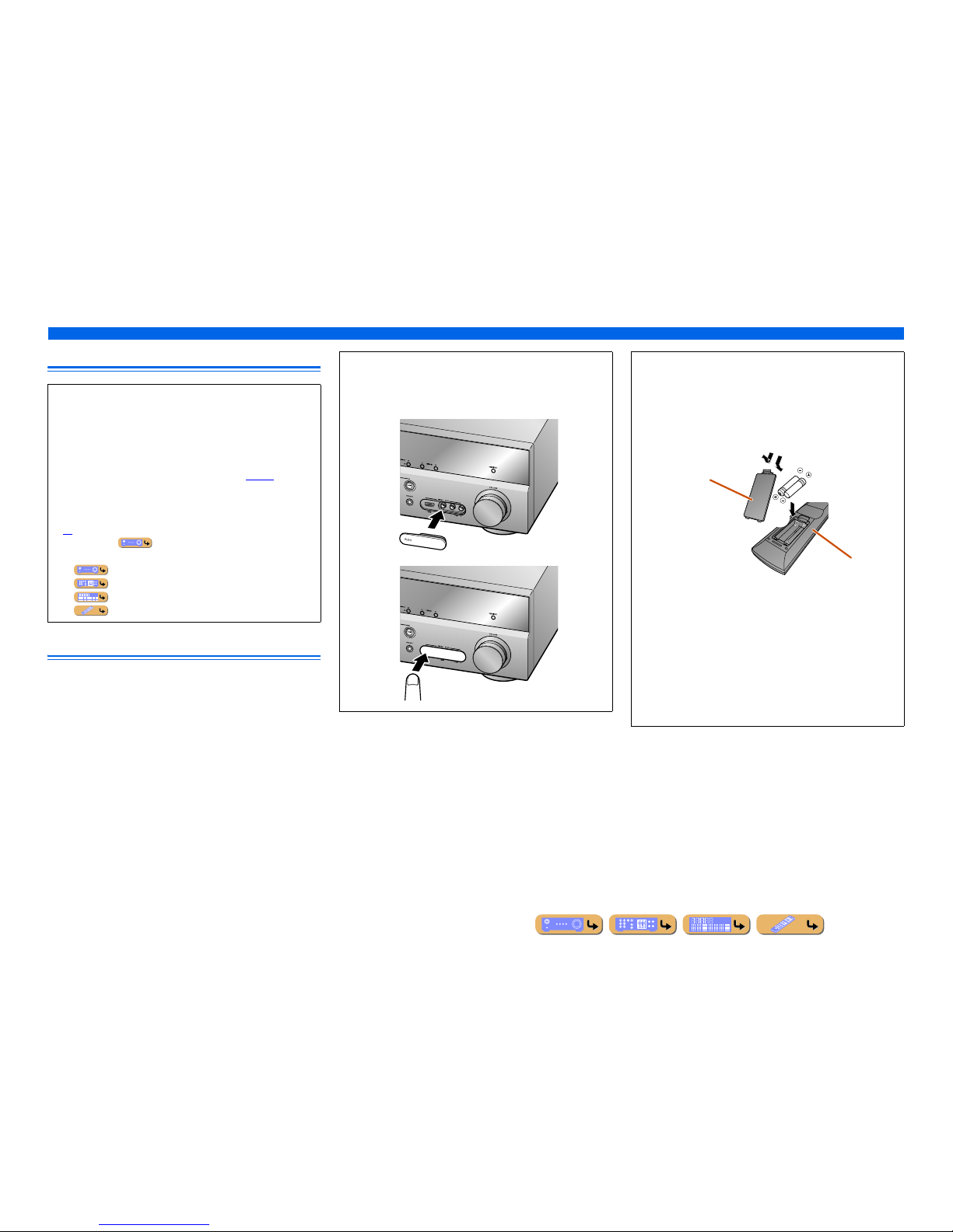
■ Attaching the VIDEO AUX input cover (supplied)
To protect against dust, attach the supplied VIDEO AUX input
cover to the VIDEO AUX jacks when you do not use the jacks.
To remove the cover, push the left section of it.
Attach the cover
PUSH
Remove the cover
■ Installing batteries in the remote control
When inserting batteries in the remote control, remove the
battery compartment cover from the reverse side of the remote
control, and insert two AAA batteries into the battery
compartment so that they match with the polarity markings (+
and -).
Replace the batteries with new ones if the remote control can
only be operated within a narrow range.
NOTE
If there are remote control codes for external components
registered to the remote control, removing the batteries for more
than 2 minutes, or leaving exhausted batteries in the remote
control, may clear the remote control codes. If this should occur,
replace the batteries with new ones, and set the remote control
codes.
a
c
b
Battery compartment
cover
Battery compartment
INTRODUCTION
En 8
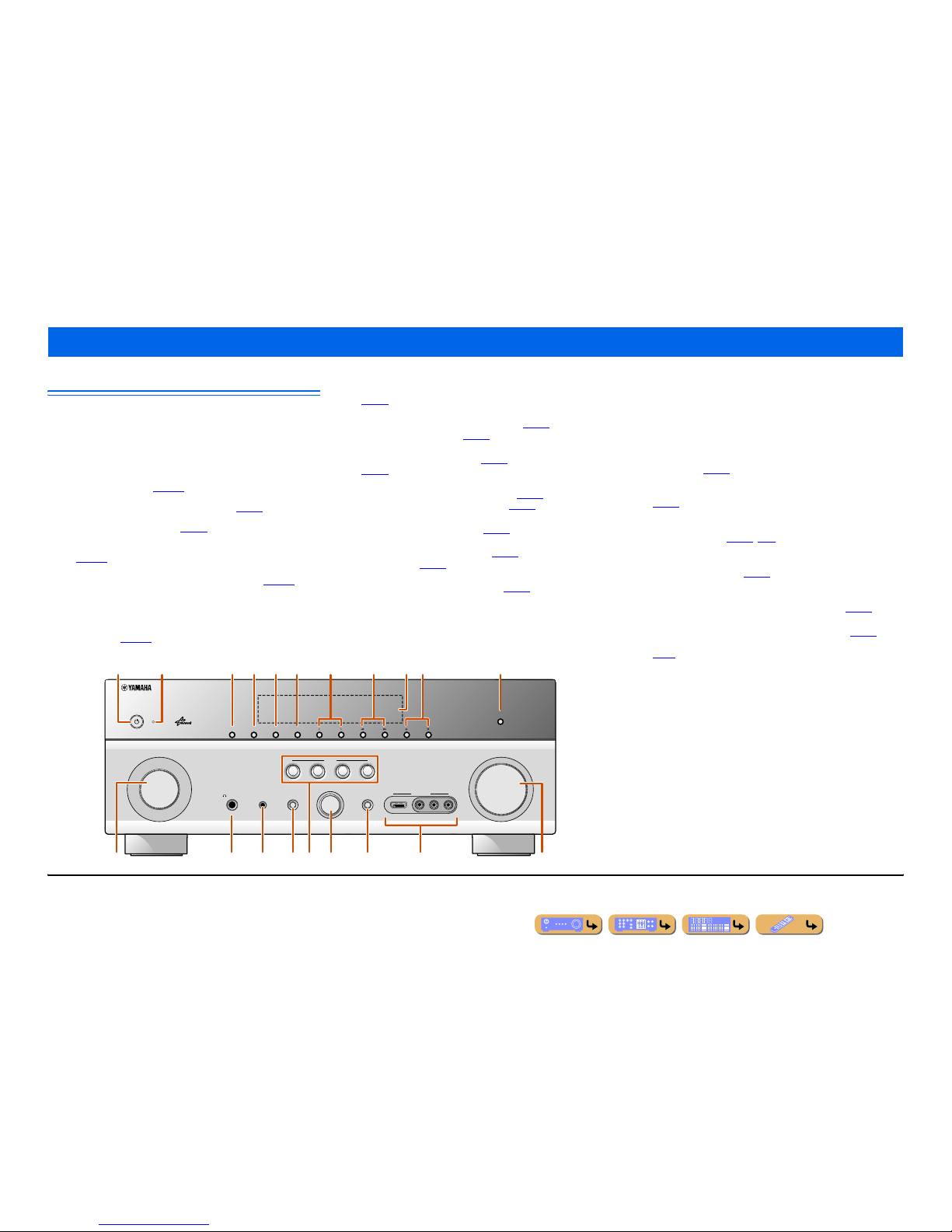
Front panel
a MAIN ZONE A (Power)
Switches this unit between on and standby mode.
b HDMI Through/iPod Charge indicator
Lights up in any of the following cases while the unit is in standby
mode.
• When the Standby Through function is enabled and audio/video from
an external component connected with HDMI is output to a TV
during standby mode (☞
p. 107).
• When an iPod/iPhone, which is placed in the Universal Dock for iPod,
is charging while the unit is in standby mode (☞
p. 81).
This indicator also lights up when the Yamaha Wireless System for
iPod is connected to this unit (☞
p. 81).
• When the Network Standby function is enabled. This function allows
this unit to be turned on by receiving a command over a network
(☞
p. 108).
c ZONE2
Switches to enable/disable the audio output to Zone2 (☞
p. 126).
d ZONE CONTROL
Switches to Zone2 operation mode. This unit, or its remote control,
can be used to select input sources or adjust volume for an external
amplifier in another room or the built-in amplifier for speakers in
another room (☞
p. 126).
e INFO
Changes the information displayed on the front panel display
(☞
p. 10).
f MEMORY
Registers FM/AM stations as preset stations (☞
p. 57) or SIRIUS
channels as preset channels (☞
p. 63). J1
g PRESET j / i
Selects an FM/AM preset station (☞
p. 59) or a SIRIUS preset channel
(☞
p. 64). J1
h FM/AM (CATEGORY l / h)
Sets the FM/AM tuner band to FM or AM (☞
p. 57). J1
Selects a channel category for a SIRIUS (☞
p. 63).
i Front panel display
Displays information on this unit (☞
p. 10).
j TUNING/CH jj / ii
Changes FM/AM tuner frequencies (☞
p. 57) or SIRIUS Satellite
Radio channels (☞
p. 63). J1
k PURE DIRECT
Switches this unit to Pure Direct mode (☞
p. 47).
l INPUT selector
Selects an input source from which to playback. Rotate this selector to
cycle through the input sources in order.
m PHONES jack
For plugging headphones in. Sound effects applied during playback
can also be heard through the headphones.
n YPAO MIC jack
Connect the supplied YPAO microphone and adjust the speaker balance
automatically (☞
p. 34).
o TONE CONTROL
Adjusts high-frequency/low-frequency output of speakers/headphones
(☞
p. 43).
p SCENE
Switches the input source, the sound program, and the HDMI OUT
with a single button (☞
p. 44, p. 90). When this unit is in standby
mode, press this key to switch on.
q PROGRAM selector
Selects a sound program (☞
p. 44). Rotate this selector to cycle
through sound programs.
r STRAIGHT
Changes a sound program to straight decoding mode (☞
p. 45).
s VIDEO AUX jacks
For connecting game consoles to this unit temporarily (☞
p. 29).
Attach the supplied VIDEO AUX input cover when not using this jack
(☞
p. 7).
t VOLU ME
Adjusts the volume level.
Part names and functions
VIDEO
AUX
PHONES
YPAO MIC
SILENT
CINEMA
TONE
CONTROL
STRAIGHT
VOLUME
TV
BD
DVD
CD
RADIO
INPUT
PROGRAM
SCENE
VIDEO
AUDIO
HDMI IN
L
R
INFO
ZONE
CONTROL
ZONE2
MAIN ZONE
MEMORY
PRESET
FM AM
CATEGORY
TUNING/CH
PURE DIRECT
rm n q
a
olts
ic f g ked h jb
p
J
1 : Usable when you have selected TUNER or SIRIUS input.
En 9
INTRODUCTION
Part names and functions
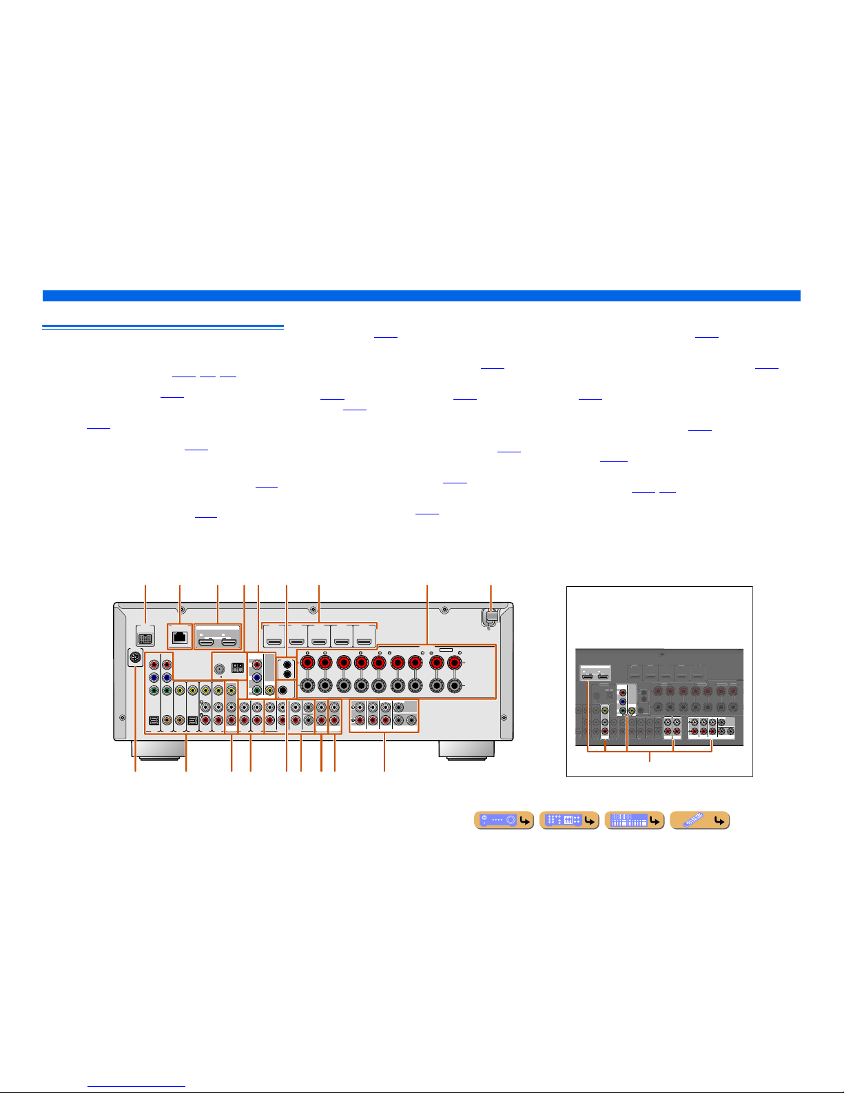
Rear panel
a DOCK jack
For connecting an optional Universal Dock for iPod ( such as
YDS-12), Wireless System for iPod (YID-W10), or Bluetooth
wireless audio receiver (YBA-10) (☞
p. 79, p. 81, p. 83).
b NETWORK port
For connecting to the network (☞
p. 32).
c HDMI OUT 1-2 jacks
For connecting an HDMI - compatible TV to output audio/video
signals (☞
p. 23).
d ANTENNA jacks
For connecting AM and FM antennas (☞
p. 33).
e MONITOR OUT jacks
f REMOTE IN/OUT jacks
For connecting an external component that supports the remote
control function (☞
p. 30).
g HDMI1-5 jacks
For connecting external components equipped with HDMIcompatible outputs to receive audio/video signals (☞
p. 25).
h SPEAKERS terminals
For connecting the front, center, surround and surround back speakers
(☞
p. 17). Connect the presence speakers (☞p. 17) or the speakers for
Zone2 (☞
p. 18) to the EXTRA SP jacks.
i Power cable
For connecting this unit to an AC wall outlet.
j SIRIUS jack
For connecting a SiriusConnect tuner (sold separately) ( ☞
p. 61).
k AV1-6 jacks
For connecting to external components equipped with audio/video
outputs to receive audio/video signals (☞
p. 26).
l AV OUT jacks
For outputting audio/video signals received when analog inputs (AV36 or AUDIO1-2) are selected (☞
p. 31).
m AUDIO1-2 jacks
For connecting external components equipped with analog audio
outputs to input sound into this unit (☞
p. 28).
n TRIGGER OUT jack
For connecting an external component that supports the trigger
function to operate it linked with operation of this unit (☞
p. 31).
o MULTI CH INPUT jacks
For connecting a player that supports a multi-channel output
(☞
p. 29).
p AUDI O O UT ja cks
For outputting audio signals received when analog jacks, such as the
AV5-6 or AUDIO1-2 are selected (☞
p. 31).
q ZONE2 OUT jacks
Outputs sound of this unit to an external amplifier set in a different
room. (☞
p. 125).
r PRE OUT terminals
For connecting a subwoofer with built-in amplifier or an external
power amplifier (☞
p. 20, p. 30).
VIDEO jack For connecting a TV capable of receiving video
input, and outputting video signals to it (☞p. 23).
COMPONENT
VIDEO jacks
For connecting TV that are compatible with
component video signals, using three cables to
output video signal (☞p. 23).
AV
OUT
AUDIO
OUT
ZONE2
OUT
SURROUND
SUR.BACK
PRE OUT
SUBWOOFER12
FRONT
CENTERSINGLE
HDMI OUT
12
ARC ARC
SELECTABLE
COMPONENT
VIDEO
VIDEO
P
R
P
B
Y
(
)
AV 4
AV 5
AV 6
AUD
IO 1
AUD
IO 2
MULTI CH INPUT
O
PTICAL
(
BD/DV
D
)
HDMI 3
HDMI 4 HDMI 5
C
ENTER
SURROUND
SURROU
ND BACK/-
S
INGL
E
FRONT
SUBWOOFE
R
SU
R.BA
CK
SURROU
ND
TRIGGER OUT
0.1A MAX.
FRONT
CENTE
R
REMOTE
OUT
S
PEAK
E
SPEAKE
FM
75
G
ND
Distinguishing the input and output jacks
The area around the audio/video output jacks is marked
in white to prevent connection errors. Use these jacks to
output audio/video signals to a TV or ot her external
component.
Output jacks
DOCK
(
TV
)
AV 3
AV 4
AV 5
AV 6
AUDIO 1
AUDIO 2
MULTI CH INPUT
(CD)
COAXIAL
OPTICAL
VIDEO
HDMI 1
(
BD/DVD
)
HDMI 2 HDMI 3
HDMI 4 HDMI 5
CENTER
SURROUND
SURROUND BACK/
BI-AMP
SINGLE
EXTRA SP
FRONT
AV
OUT
SUBWOOFER
AUDIO
OUT
ZONE2
OUT
SUR.BACK
SURROUND
SURROUND
SUR.BACK
PRE OUT
SUBWOOFER12
FRONT
TRIGGER OUT
+12V
0.1A MAX.
FRONT
CENTER
IN
REMOTE
OUT
CENTERSINGLE
HDMI OUT
12
ARC ARC
SELECTABLE
SPEAKERSSPEAKERS
OPTICAL
AV 1
AV 2
COAXIAL
COMPONENT
VIDEO
P
R
P
B
Y
SIRIUS
COMPONENT
VIDEO
VIDEO
MONITOR OUT
P
R
P
B
Y
ZONE2/PRESENCE
ANTENNA
FM
75
GND
AM
NETWORK
aecg ihf
pqjklmo r
db
n
En 10
INTRODUCTION
Part names and functions
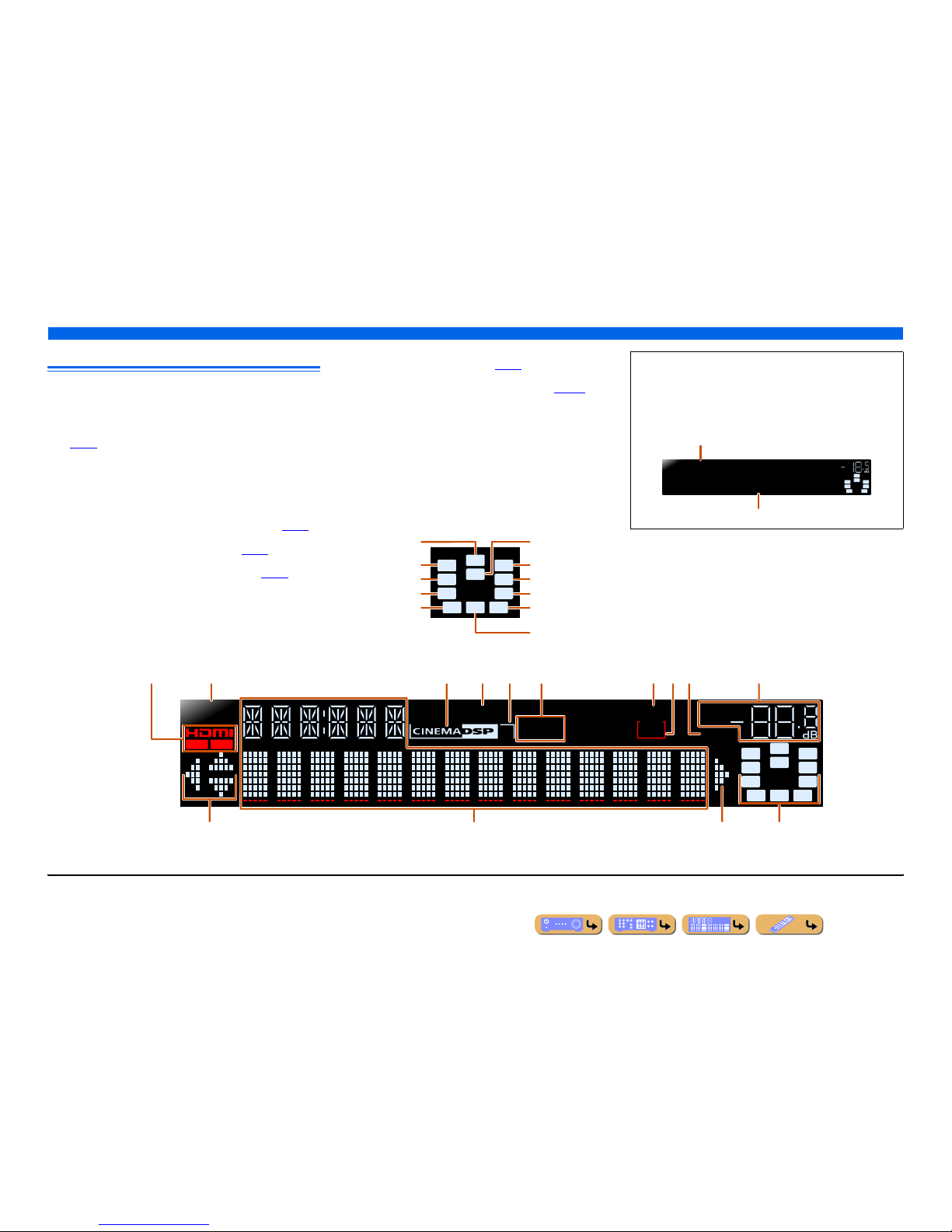
Front panel display
a HDMI indicator
Lights up when this unit detects the external component connected to
the HDMI1-5 jacks.
OUT 1/OUT 2 indicators
Indicate which HDMI OUT jack outputs audio/video signals
(☞
p. 23).
b SIRIUS indicator
Lights up when a SiriusConnect tuner is selected as an input source.
c CINEMA DSP indicator
Lights up when a sound field effect that uses CINEMA DSP
technology is selected.
d ENHANCER indicator
Lights up when the Compressed Music Enhancer is active (☞
p. 47).
e CINEMA DSP 3D indicator
Lights up when CINEMA DSP 3D is activated (☞
p. 46).
f Tuner indicators
Light up according to the status of a received station (☞
p. 57).
g SLEEP indicator
Lights up when the sleep timer is on (☞
p. 11).
h ZONE2 indicator
Lights up when the audio output to Zone2 is enabled (☞
p. 126).
i MUTE indicator
Flashes when audio is muted.
j VOLUME indicator
Displays the current volume level.
k Cursor indicators
Light up if corresponding cursors on the remote control are available
for operations.
l Multi information display
Displays a range of information on menu items and settings.
m Speaker indicators
Indicate speaker terminals from which signals are output.
SW
C
LR
SL SR
SBL SBRSB
PR
PL
Front speaker L
Surround speaker L
Subwoofer
Front speaker R
Surround speaker R
Center speaker
Surround back
speaker L
Surround back
speaker R
Surround back
speaker J1
Presence speaker L
Presence speaker
R
■ Switching information on the front panel display
The front panel can display sound programs and surround
decoder names as well as the active input source.
Press fINFO repeatedly to cycle through displayed
informations. J2
SWSW
C
LR
SL SR
SBL SBR
STRAIGHT
HDMI1
VOL.
Input source name
Sound program (DSP program)
STEREO
SLEEP
VOL.
TUNED
SW
C
LR
SL SR
MUTE
ENHANCER
OUT 1 OUT 2
3
ZONE
2
SBL SBRSB
PR
PL
SIRIUS
kl mk
acdebfgjih
J
1 : “SB” is displayed when using a 6.1-channel configuration only.
J
2 : During FM/AM reception, the frequency is displayed instead of th e input source. During SIRIUS Satellite Radio signals reception, the channel is displayed instead of the input source.
En 11
INTRODUCTION
Part names and functions
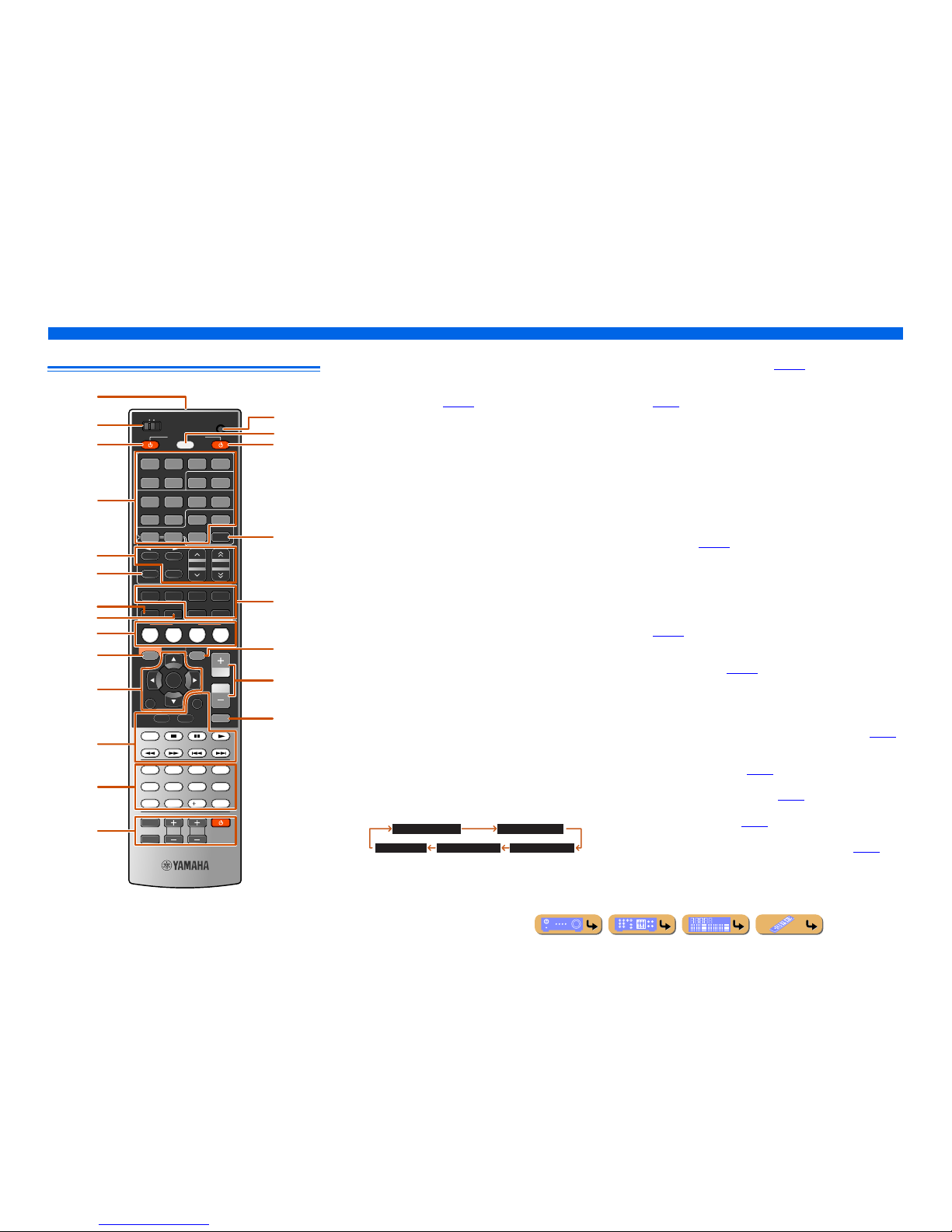
Remote control
a Remote control signal transmitter
Transmits infrared signals.
b MAIN/ZONE2
Switches the zone to be operated by the remote control between the
Main zone and Zone2 (☞
p. 126).
c SOURCE A (SOURCE Power)
Switches an external component on and off.
d Input selector
Select an input source on this unit from which to playback.
e Radio control keys
Operates the FM/AM tuner. These keys are used when using the tuner
input.
f INFO
Cycles the information displayed on the front panel display (the name
of the currently selected input source, the sound program, the
surround decoder, the FM/AM tuner frequency, etc.).
g SLEEP
Switches this unit to standby mode automatically after a specified
period of time has elapsed (sleep timer). Press this key repeatedly to
set the time for the sleep timer function.
The SLEEP indicator lights up when the sleep timer is on.
h PAR TY
Switches the party mode on and off (☞
p. 126).
i SCENE
Switch the input source and the sound program with a single button
(☞
p. 44). When this unit is in standby mode, press this key to switch on.
j ON SCREEN
Turns on and off the ON SCREEN menu.
k Cursor B / C / D / E, ENTER, RETURN
l External component operation keys
Operate recording, playback, and menu displays etc. for external
components (☞
p. 115).
m Numeric keys
Enter numbers.
n TV control keys
Operate a monitor such as a TV.
o CODE SET
Sets remote control codes for external component operations
(☞
p. 116).
p SOURCE/RECEIVER
Switches remote control key function to operate this unit or an
external component (☞
p. 115). Operate an external component when
this key glows green, or this unit when this key glows orange.
q RECEIVER A (RECEIVER Power)
Switches this unit between on and standby mode.
r HDMI OUT
Switches the output jack connected to an HDMI compatible TV (☞
p. 42).
s Sound selection keys
Switch between the sound field effect (sound program) you are using
and the surround decoder (☞
p. 44).
t OPTION
Turns on and off the Option menu (☞
p. 52).
u VOLU ME +/-
Adjust the volume level (☞
p. 42).
v MUTE
Turns the mute function of the sound output on and off (☞
p. 42).
SCENE
RETURN
VOLUME
ENHANCER
SUR. DECODE
STRAIGHTSLEEP PURE DIRECT
HDMI
AV
AUDIO
1234
125
V-AUX
FM
INFO
MEMORY
AM
PRESET
PART Y
MOVIE MUSIC
BD
DVD
TV
CD
RADIO
MUTE
ENTER
7856
90
10
1234
REC
ENT
TV
TV VOL TV CH
TOP
MENU
POP-UP
MENU
DISPLAY
SOURCE
MAIN
ZONE 2
RECEIVER
CODE SET
INPUT
MUTE
DOCK
HDMI OUT
MULTI
OPTION
ON SCREEN
5
1234
6
SIRIUSTUNER
TUN./CH
CATEGORY
HOLD
NET
a
c
b
e
i
j
t
u
v
m
n
k
f
l
g
h
p
q
r
o
d
s
HDMI1-5 HDMI1-5 jacks
V-AU X Front panel VIDEO AUX jacks
AUDI O1-2 AUDIO1-2 jacks
AV1 -6 AV1-6 jacks
NET Rhapsody service, SIRIUS internet radio, internet
radio, or a PC connected to the NETWORK por t.
MULTI CH INPUT MULTI CH INPUT jacks
DOCK A Universal Dock for iPod, Wireless System for
iPod, or Bluetooth wireless audio rec eiver
connected to the DOCK jack.
TUNER FM/AM tuner
SIRIUS A SIRIUS tuner connected to the SIRIUS jack.
FM Sets the FM/AM tuner band to FM.
AM
(CATEGORY D / E)
Sets the FM/AM tuner band to AM.
Selects a channel category for a SIRIUS.
MEMORY Presets radio stations.
PRESET F / G Selects a preset station.
TUN./CH H / I Changes tuning frequencies or SIRIUS Satellite
Radio channels.
Sleep 120min. Sleep 90min.
Sleep 60min.Sleep 30min.Sleep Off
Cursor B / C / D / E Select menu items and change settings when
menus, etc, are displayed.
ENTER Confirms a selected item.
RETURN Returns to the previous screen when menus are
displayed, or close the menu.
INTRODUCTION
Part names and functions
En 12
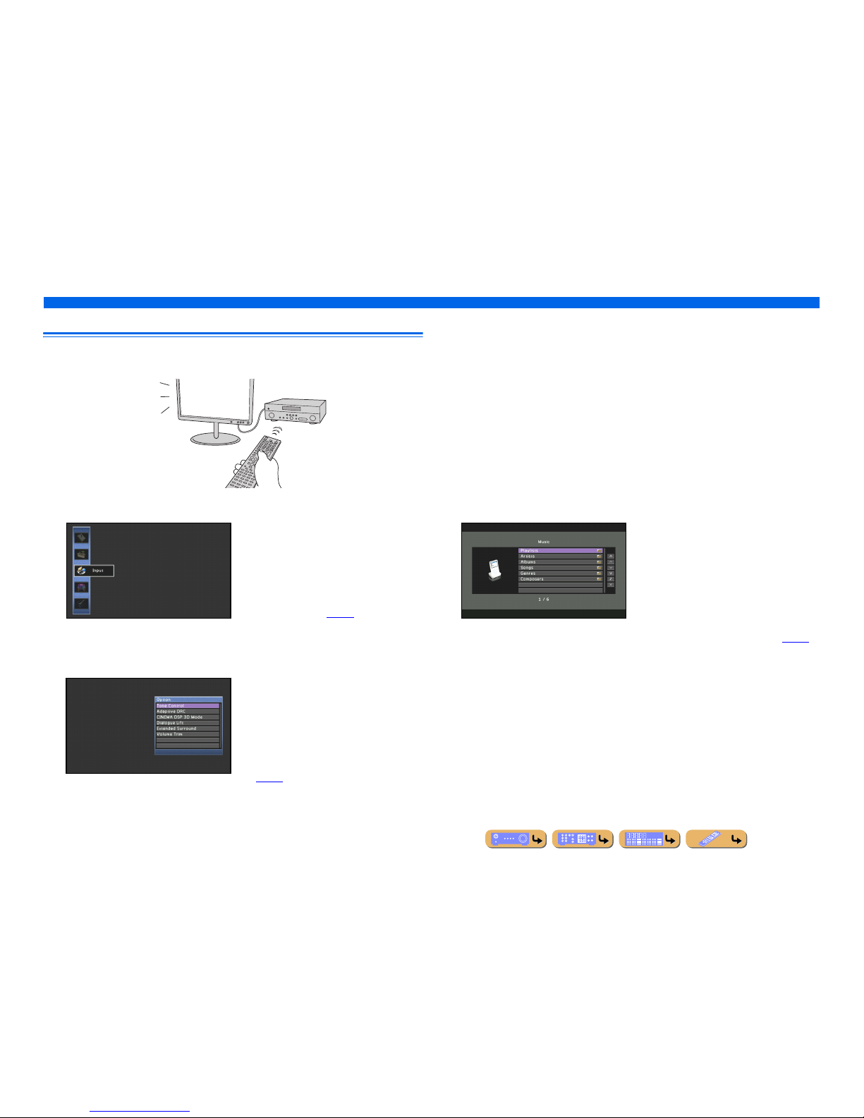
On-screen display
When a TV is connected to this unit, the supplied remote control can be used to specify and verify this
unit’s settings via menus and options displayed on the TV screen.
The following displays are available in the on-screen display.
ON SCREEN menu
Press jON SCREEN to display the ON
SCREEN menu.
Detailed settings for this unit can be
configured. Use this menu to select desired
settings, change their values, or check the
current status of this unit.
Refer to “SETUP” (☞
p. 86) for details.
Option menu
Press tOPTION to display the Option menu.
Configure the optional settings for each input
source. Settings such as “Tone Control” and
“Volume Trim” are applied to this unit
regardless of the input source.
Refer to “Configuring settings specific to an
individual input source (Option menu)”
(☞
p. 52) for details.
Content window
Press dInput selector to display the
Content window.
Includes the Browse view and the Now
Playing view. The Now Playing view displays
the status of the source from which music is
currently played back. Adjust settings for
music content from the Browse view.
Refer to “Confirming and operating input
sources from the Content window” (☞
p. 56)
for details.
En 13
CONNECTIONS
This unit uses acoustic field effects and sound decoders to bring you the impact of a real movie theater or concert hall. These effects will be brought to you with ideal speaker positioning and
connections in your listening environment.
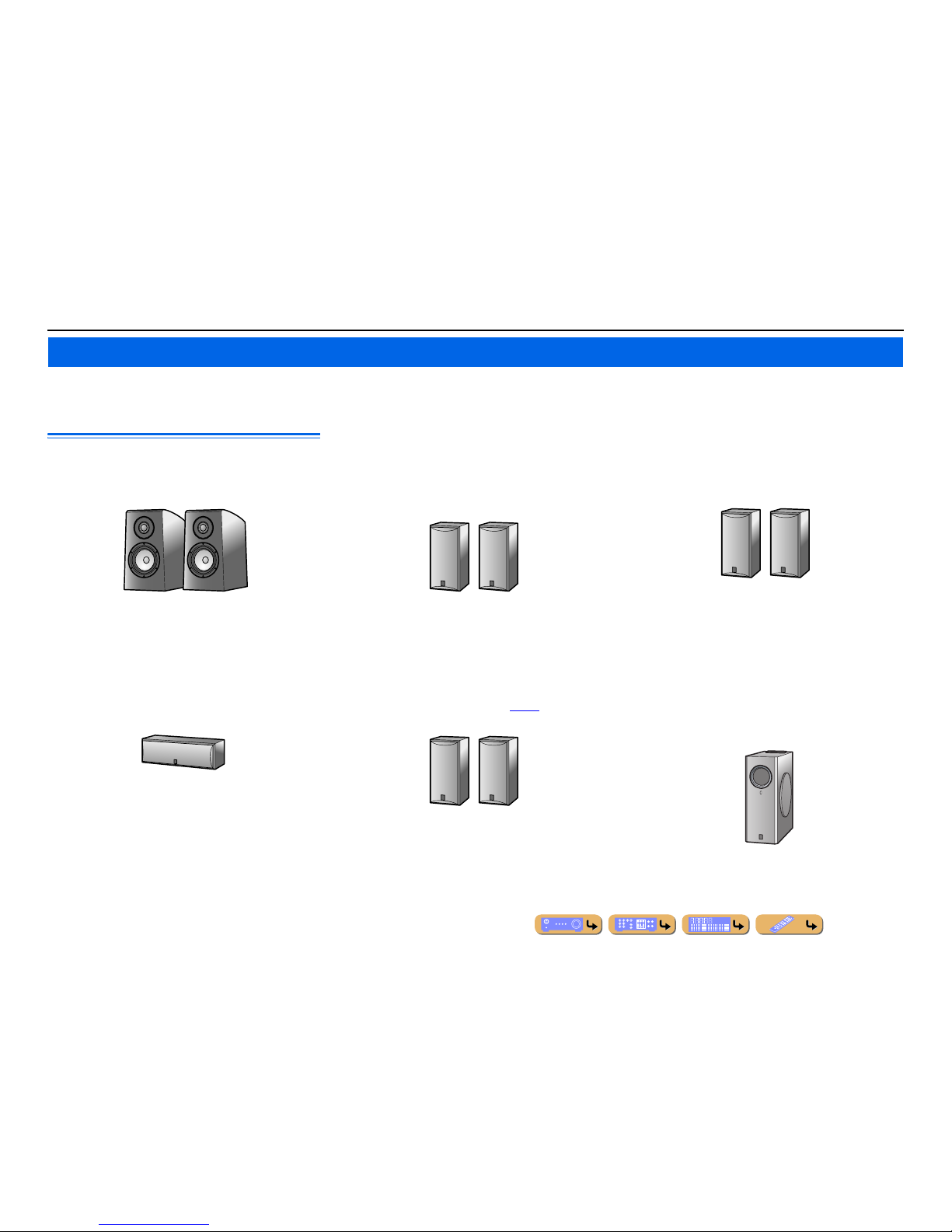
Speaker channels and functions
■
Front left and right speakers
The front speakers are used for the front channel sounds (stereo
sound) and effect sounds.
Front speaker layout:
Place these speakers at an equal distance from the ideal listening
position in the front of the room. When using a projector screen,
the appropriate top positions of the speakers are about 1/4 of the
screen from the bottom.
■
Center speaker
The center speaker is for the center channel sounds (dialog, vocals,
etc.).
Center speaker layout:
Place it halfway between the left and right front speakers. When
using a TV, place the speaker just above or just under the center of
the TV with the front surfaces of the TV and the speaker aligned.
When using a screen, place it just under the center of the screen.
■
Surround left and right speakers
The surround speakers are for effect and vocal sounds when
playing back a 5.1-channel source or higher. If used with no
surround back speaker when playing back a 6.1-channel source or
higher (including a surround back channel), the sound of the
surround back channel is distributed between the left and right
surround speakers.
Surround speaker layout:
Place the speakers at the rear of the room on the left and right sides
facing the listening position. They should be placed between 60
degrees and 80 degrees from the listening position and with the
speaker tops at a height of 4.9 – 5.9 ft. (1.5 – 1.8 m) from the floor.
■
Presence left and right speakers
The presence speakers are used for front effect sounds. When used
in combination with the sound programs (☞
p. 44), a sound with a
richer and more spatial presence is possible.
Presence speaker layout:
Place the left and right presence speakers 1.6 – 3.3 ft. (0.5 – 1 m) to
the outside of the left and right front speakers respectively. The
tops of the presence speakers should be 5.9 ft. (1.8 m) above the
floor.
■
Surround back left and right speakers
The surround back speakers are for rear effect sounds when
playing back a 6.1-channel source or higher. If used with only one
surround back speaker when playing back a 7.1-channel source or
higher, the sound of the left and right surround back channel is
mixed and output from a single speaker.
Surround back speaker layout:
When used with 7.1ch sound, arrange the left and right speakers
towards the listening position, to the rear of the listening position.
Arrange the left and right speakers at least 1 ft. (30 cm) apart. The
same separation as with the front left and right speakers is optimum.
When used with 6.1ch sound, arrange these to the rear of the
listening position.
■
Subwoofer
The subwoofer speaker is used for bass sounds and low-frequency
effect (LFE) sounds included in Dolby Digital and DTS. Use a
subwoofer that is equipped with built-in amplifier.
Subwoofer speaker layout:
Place it to the outside of the front left and right speakers facing
slightly inward to reduce echoes from the wall. You can use one or
two subwoofers.
Connecting speakers
E.g.
E.g.
E.g.
E.g.
E.g.
E.g.
CONNECTIONS
Connecting speakers
En 14
Speaker layout
In addition to the 7.1-channel speaker layout, a variety of speaker configurations can be specified with
presence speaker connection, bi-amp connection or the Zone2 function.
And, this unit is equipped with “Power Amp Assign” function which can easily apply the appropriate
speaker setting to this unit according to your speaker configuration.
■
Connection of speakers
Connect the speakers to the appropriate jacks shown in the table for each speaker layout. Refer to
“Connecting speakers and subwoofers” (☞
p. 17) for details on connecting speakers.
You can also use two subwoofers by connecting them to both SUBWOOFER1 and SUBWOOFER2
jacks. In this case, monaural sound of subwoofer channel is output from both speakers.
■
Assigning a speaker configuration
A speaker configuration must be assigned to this unit to activate the speakers. Use the Power Amp
Assign function to apply the appropriate settings shown in the table for each speaker layout. Refer to
“Power Amp Assign” (☞
p. 99) for details on setting.
■
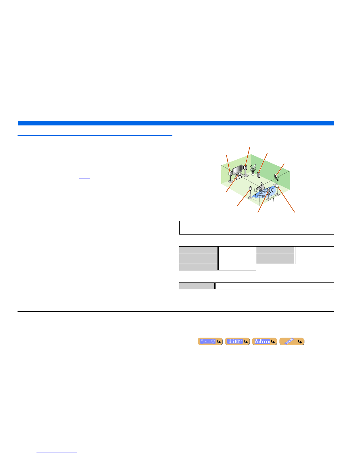
Enjoying the 7.1 channel audio source
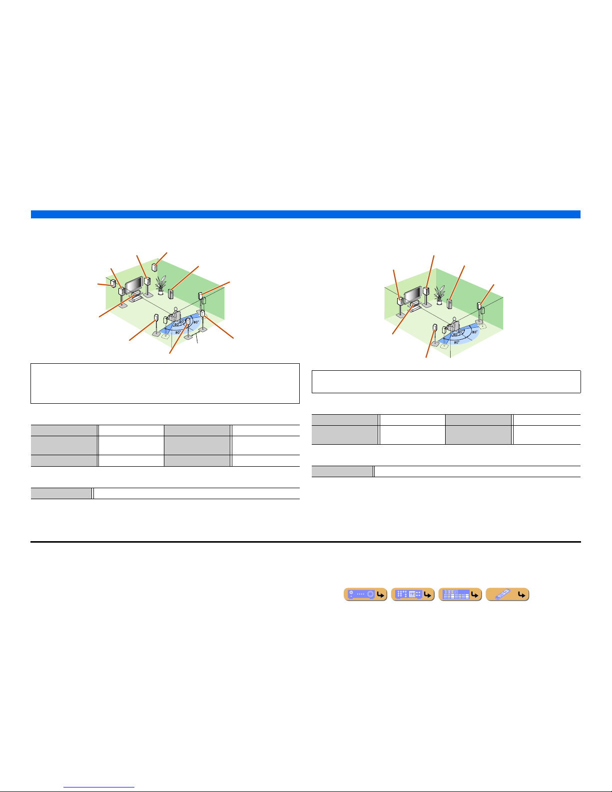
■ 7.1-channel speaker layout (7 speakers + subwoofer)
■ Connections of speakers
■ Assigning a speaker configuration
Audio from a 7.1-channel audio source can be played back with no degradation with this speaker
configuration.
FRONT jacks Front L/R speakers SURROUND BACK jacks Surround back L/R speakers
CENTER jack Center speaker SUBWOOFER
(PRE OUT) jack
Subwoofer
SURROUND jacks Surround L/R speakers
Power Amp Assign 7ch Normal (Default)
Front L speaker
Front R speaker
Subwoofer
Center speaker
Surround L speaker
Surround R speaker
Surround back R speaker
Surround back L speaker J1
12 in (30 cm)
or more
J
1 : The sound of surround back channel can also be output from a single surround back speaker. When only one surround back
speaker is used, connect it to the SURROUND BACK L (SINGLE) jack and place it directly behind the listening position.
CONNECTIONS
Connecting speakers
En 15
■
Adding the presence speakers for a richer sound field effect
■ Presence speaker layout (7 speakers + subwoofer + presence speakers)
■ Connections of speakers
■ Assigning a speaker configuration
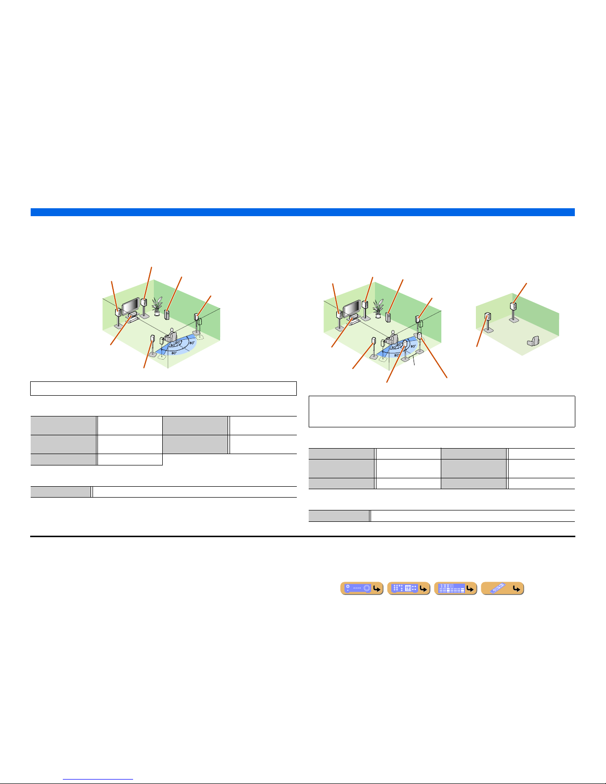
■
Enjoying the audio source without surround back speakers
■ 5.1-channel speaker layout (5 speakers + subwoofer)
■ Connections of speakers
■ Assigning a speaker configuration
This unit automatically selects the presence speakers or surround back speakers to output sounds
according to the selected sound program.
When the sound program is changed, the speakers that output the sound are switched between the
presence speakers and surround back speakers automatically. J2
FRONT jacks Front L/R speakers SURROUND BACK jacks Surround back L/R speakers
CENTER jack Center speaker SUBWOOFER
(PRE OUT) jack
Subwoofer
SURROUND jacks Surround L/R speakers EXTRA SP jacks Presence L/R speakers
Power Amp Assign 7ch Normal (Default)
Front L speaker
Front R speaker
Subwoofer
Center speaker
Surround L speaker
Surround R speaker
Presence R speaker
Presence L speaker
Surround back R speaker
Surround back L speaker J1
12 in (30 cm) or
more
This unit can mix 7.1-channel audio source down to 5.1-channel sound. This enables 7.1-channel
sound without surround back speakers.
FRONT jacks Front L/R speakers SURROUND jacks Surround L/R speakers
CENTER jack Center speaker SUBWOOFER
(PRE OUT) jack
Subwoofer
Power Amp Assign 7ch Normal (Default)
Front L speaker
Front R speaker
Subwoofer
Center speaker
Surround L speaker
Surround R speaker
J
1 : The sound of surround back channel can also be output from a single surround back speaker. When only one surround back
speaker is used, connect it to the SURROUND BACK L (SINGLE) jack and place it directly behind the listening position.
J
2 : Sound cannot be output from the surround back speakers when i t is output from the speakers connected to the EXTRA SP
jacks.
CONNECTIONS
Connecting speakers
En 16
■
Using the front speakers that support bi-amp connections for a
high quality sound
■ 5.1-channel speaker layout (Front speakers (Bi-amp) + 3 speakers)
■ Connections of speakers
■ Assigning a speaker configuration
■
Using speakers in two rooms (Zone2 function)
■ 7.1-channel speaker layout + Zone2 (7 speakers (in main zone) + subwoofer (in
main zone) + front speakers (in secondary zone))
■ Connections of speakers
■ Assigning a speaker configuration
Using the front speakers that support bi-amp connections reproduces a high quality sound.
FRONT jacks Front L/R speakers
(bi-amp)
SURROUND BACK jacks Front L/R speakers (bi-amp)
CENTER jack Center speaker SUBWOOFER
(PRE OUT) jack
Subwoofer
SURROUND jacks Surround L/R speakers
Power Amp Assign 5ch BI-AMP
Front L speaker
(Bi-amp connection)
Front R speaker
(Bi-amp connection)
Center speaker
Surround L speaker
Surround R speaker
Subwoofer
In addition to the main room, speakers in another room can also be controlled.
When the built-in amplifier assigned to speakers in another room is turned on, sound output
automatically switches from the surround back speakers to the speakers in the other room. J2
FRONT jacks Front L/R speakers SURROUND BACK jacks Surround back L/R speakers
CENTER jack Center speaker SUBWOOFER
(PRE OUT) jack
Subwoofer
SURROUND jacks Surround L/R speakers EXTRA SP jacks Zone2 speakers
Power Amp Assign 7ch + 1ZONE
Front L speaker
Front R speaker
Center speaker
Subwoofer
Surround R speaker
Surround L speaker
Surround back L speaker J1
Surround back R
speaker
12 in (30 cm)
or more
Front R speaker
Front L speaker
Main zone Zone2
J
1 : The sound of surround back channel can also be output from a single surround back speaker. When only one surround back
speaker is used, connect it to the SURROUND BACK L (SINGLE) jack and place it directly behind the listening position.
J
2 : Sound cannot be output from the surround back speakers when i t is output from the speakers connected to the EXTRA SP
jacks.
CONNECTIONS
Connecting speakers
En 17
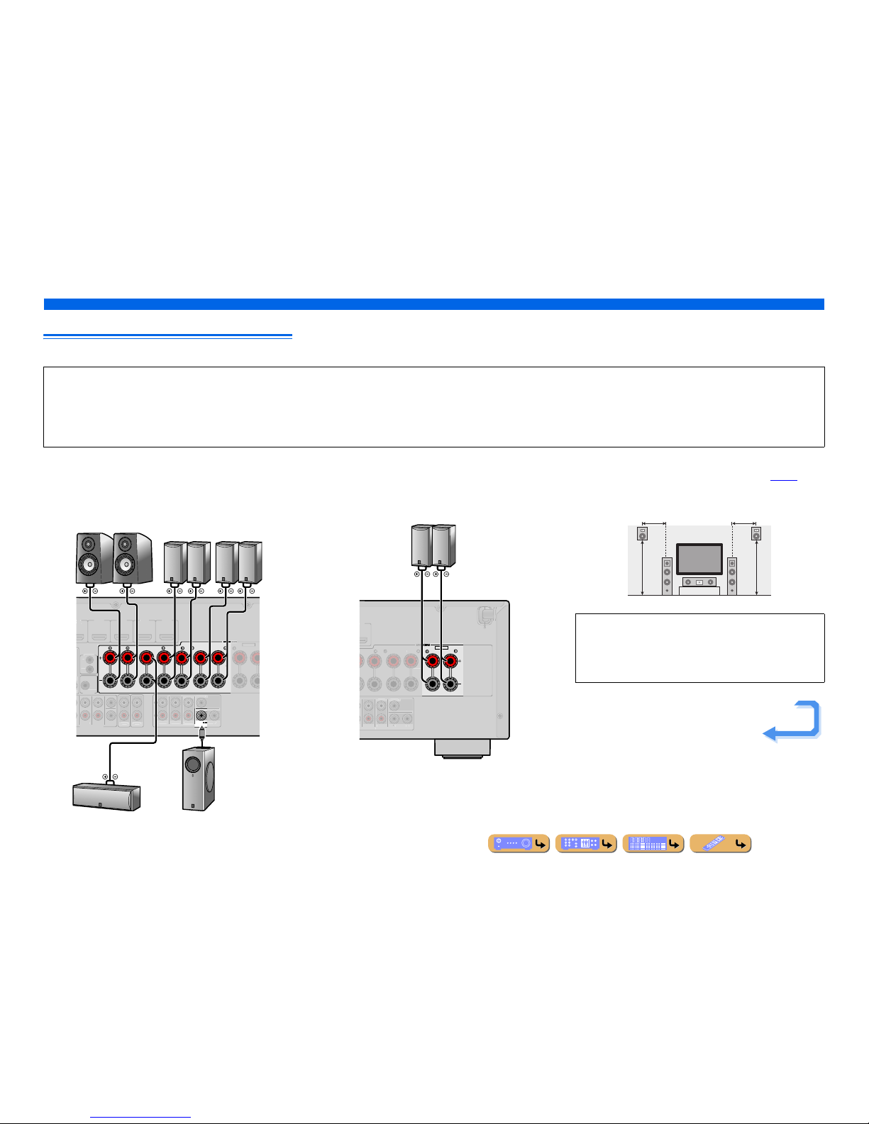
Connecting speakers and subwoofers
Connect your speakers to their respective terminals on the rear panel.
■ Front/Center/Surround/Surround back speaker and
Subwoofer connection
When connecting only one surround back speaker, connect the
speaker to the SURROUND BACK L (SINGLE) jacks.
■ Presence speaker connection
When using the presence speakers, connect the speakers to the
EXTRA SP jacks as shown in the diagram below.
The presence speakers (PL/PR) that output front effect sounds can
be connected to this unit. With the sound programs (☞
p. 48),
sound with a richer and more spatial presence can be created.
CAUTION
• Remove the AC power cable of this unit from the power outlet before connecting the speakers.
• Generally speaker cables consist of two parallel insulated cables. One of these cables is a different color, or has a line running along it, to indicate different polarity. Insert the different colored (or lined) cable into the “+”
(positive, red) terminal on this unit and the speakers, and the other cable into the “–” (negative, black) terminal.
• Be careful that the core of the speaker cable does not touch anything or come into contact with the metal areas of this unit. This may damage this unit or the speakers. If the speaker cables short circuit, “CHECK SP
WIRES!” will appear on the front panel display when this unit is switched on.
CENTER
SURROUND
SURROUND BACK/
BI-AMP
SINGLE
FRONT
1
MULTI CH INPUT
DVD
)
H
DMI
3
HDMI 4 HDMI
5
SUBWOOFE
R
AUDI
O
OU
T
Z
ONE2
O
UT
S
UR.BACKSURROUND
SURROUNDSU
R.BACK
PRE
OUT
WOOFER
FRO
NT
TRIGG
ER
OUT
0.1A MAX
.
CENTE
R
E
XTRA S
P
IN
REMOTE
OUT
C
ENTERSINGLE
SPEAKERS
SPEAKERS
ZONE2/PRESENC
E
SubwooferCenter speaker
Front speaker Surround
speaker
Surround back
speaker
RL
RL RL
EXTRA SP
ZONE2/PRESENCE
MI 5
SURROUND
S
URROUND BACK/
-
SING
LE
S
URROUND
SUR.BACK
PRE OUT
S
UBWOOFE
R
1
2
C
ENTERSINGLE
SPEA
SPEA
Presence speaker
RL
• Connection of presence speakers is recommended to take full
advantage of the effects of CINEMA DSP sound programs.
• Although you can connect both surround back speakers and
presence speakers to this unit, you cannot output sounds from
those speakers at the same time.
0.5 – 1 m 0.5 – 1 m
PL PR
FL FR
1.8 m 1.8 m
Continues to the
next page
CONNECTIONS
Connecting speakers
En 18
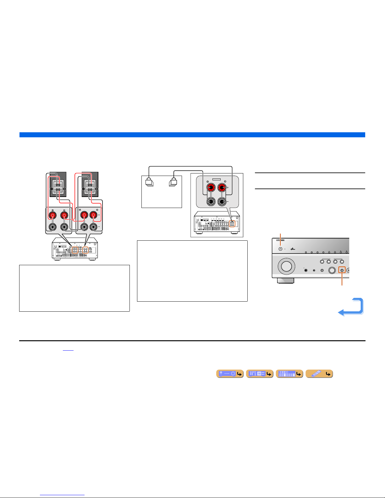
■ Bi-amp connection
This unit can be connected to speakers that support bi-amp
connections. When connecting speakers, connect the FRONT jacks
and the SURROUND BACK/BI-AMP jacks as in the diagram
below. Configure the bi-amp settings to activate connections.
■ Multi-zone audio system using the internal
amplifier of this unit
Connect the speakers in the second zone to the EXTRA SP jacks as
in the diagram below.
■
Changing speaker impedance
This unit is configured for 8 Ω speakers at the factory setting.
When connecting to 6 Ω speakers, carry out the following
procedure to switch to 6 Ω. When this unit is configured for 6 Ω
speakers, 4 Ω speakers can also be used as the front speakers.
1
Switch this unit to the standby mode.
2
Press MAIN ZONE A while pressing and holding
STRAIGHT on the front panel.
Release the keys when “ADVANCED SETUP” is displayed on
the front panel display.
After approximately a few seconds, the top menu item is
displayed. J1
NOTES
• Before making bi-amplification connections, remove any
brackets or cables that connect a woofer with a tweeter. Refer to
the instruction manuals of speakers for details. When not making
bi-amplification connections, make sure that the brackets or
cables are connected before connecting the speaker cables.
• If connecting a bi-amp, then surround back speakers cannot be
used.
DOCK
(
TV
)
A
V
3
A
V
4
A
V
5
A
V
6
AUDIO 1
AUDIO 2
M
U
L
T
I C
H
IN
P
U
T
(CD)
COAXIAL
OPTICAL
VIDEO
HDMI 1
(
BD/DVD
)
HDMI 2 HDMI 3
HDMI 4 HDMI 5
CENTER
SURROUND
SURROUND BACK/
BI-AMP
SINGLE
EXTRA SP
FRONT
AV
OUT
SUBWOOFER
AUDIO
OUT
ZONE2
OUT
SUR.BACK
SURROUND
SURROUND
SUR.BACK
PRE OUT
SUBWOOFER12
FRONT
TRIGGER OUT
+12V
0.1A MAX.
FRONT
CENTER
IN
REMOTE
OUT
CENTERSINGLE
HDMI OUT
12
ARC ARC
SELECTABLE
SPEAKERSSPEAKERS
OPTICAL
A
V
1
A
V
2
COAXIAL
COMPONENT
VIDEO
P
R
P
B
Y
SIRIUS
COMPONENT
VIDEO
VIDEO
MONITOR OUT
P
R
P
B
Y
ZONE2/PRESENCE
NETWORK
ANTENNA
FM
75
GND
AM
FRONT
SINGLE
SURROUND BACK/
BI-AMP
CAUTION
The EXTRA SP jacks of this unit should not be connected to a
Passive Loudspeaker Selector Box or more than one loudspeaker
per channel.
Connection to a Passive Loudspeaker Selector Box or multiple
speakers per channel could create an abnormally low impedance
load resulting in amplifier damage. See this owner’s manual for
correct usage.
Compliance with minimum speaker impedance information for all
channels must be maintained at all times. This information is found
on the back panel of this unit.
DOCK
(
TV
)
A
V
3
A
V
4
A
V
5
A
V
6
AUDIO 1
AUDIO 2
M
U
L
T
I
C
H
IN
P
U
T
(CD)
COAXIAL
OPTICAL
VIDEO
HDMI 1
(
BD/DVD
)
HDMI 2 HDMI 3
HDMI 4 HDMI 5
CENTER
SURROUND
SURROUND BACK/
BI-AMP
SINGLE
EXTRA SP
FRONT
AV
OUT
SUBWOOFER
AUDIO
OUT
ZONE2
OUT
SUR.BACK
SURROUND
SURROUND
SUR.BACK
PRE OUT
SUBWOOFER12
FRONT
TRIGGER OUT
+12V
0.1A MAX.
FRONT
CENTER
IN
REMOTE
OUT
CENTERSINGLE
HDMI OUT
12
ARC ARC
SELECTABLE
SPEAKERSSPEAKERS
OPTICAL
A
V
1
A
V
2
COAXIAL
COMPONENT
VIDEO
P
R
P
B
Y
SIRIUS
COMPONENT
VIDEO
VIDEO
MONITOR OUT
P
R
P
B
Y
ZONE2/PRESENCE
NETWORK
ANTENNA
FM
75
GND
AM
ZONE2/PRESENCE
EXTRA SP
Zone2
PHONES
YPAO MIC
SILENT
CINEMA
TONE
CONTROL
STRAIGHT
TV
BD
DVD
CD
RADIO
INPUT
PROGRAM
SCENE
H
INFOZONE
CONTROL
ZONE2
MAIN ZONE
MEMORY
PRESET
FM AM
CATEGORY
MAIN ZONE A
STRAIGHT
Continues to the
next page
J
1 : Refer to the “Extended functionality that can be configured as needed
(Advanced Setup menu)” (☞
p. 118) for details on the Advanced Setup menu.
CONNECTIONS
Connecting speakers
En 19
3
Check that “SP IMP.” is displayed on the front panel.
4
Press STRAIGHT repeatedly to select a “6ΩMIN.”
5
Switch this unit to the standby mode, and then
switch it on again.
The power turns on, when the settings you made has been
configured.
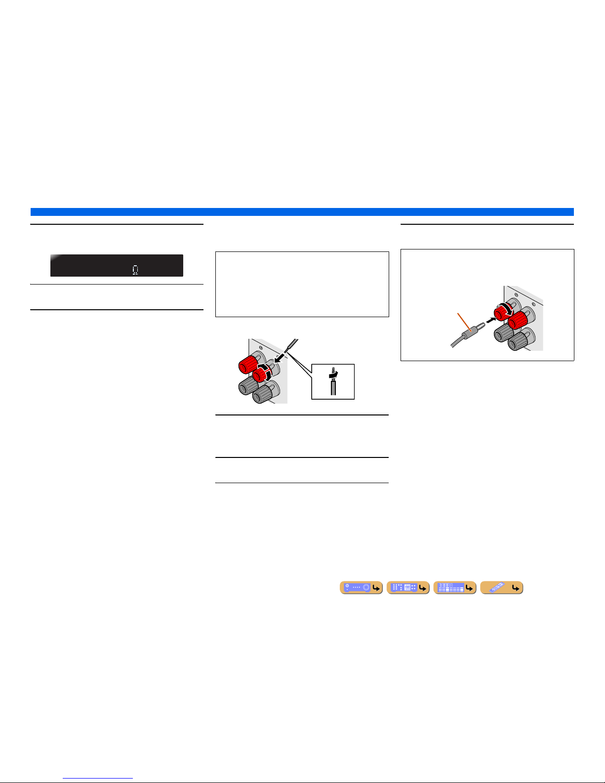
■
Connecting speakers
This type of jack can connect to the following speakers or
connection.
1
Remove approximately 0.4 in. (10 mm) of insulation
from the ends of the speaker cables, and twist the
bare wires of the cables together firmly so that they
will not cause short circuits.
2
Loosen the speaker terminals.
3
Insert the bare wire of the speaker cable into the gap
on the side of the terminal.
4
Tighten the terminal.
SPIMP.-8MIN
• Front L/R speakers
• Center speaker
• Surround L/R speakers
• Surround back L/R speakers
• Presence L/R speakers
• Zone2 speakers
• Bi-amp connection (Front L/R speakers)
FRONT
2
2
3
1
4
4
Connecting the banana plug
Tighten the knob, and then insert the banana plug into the end of
the terminal.
FRONT
Banana plug
CONNECTIONS
Connecting speakers
En 20
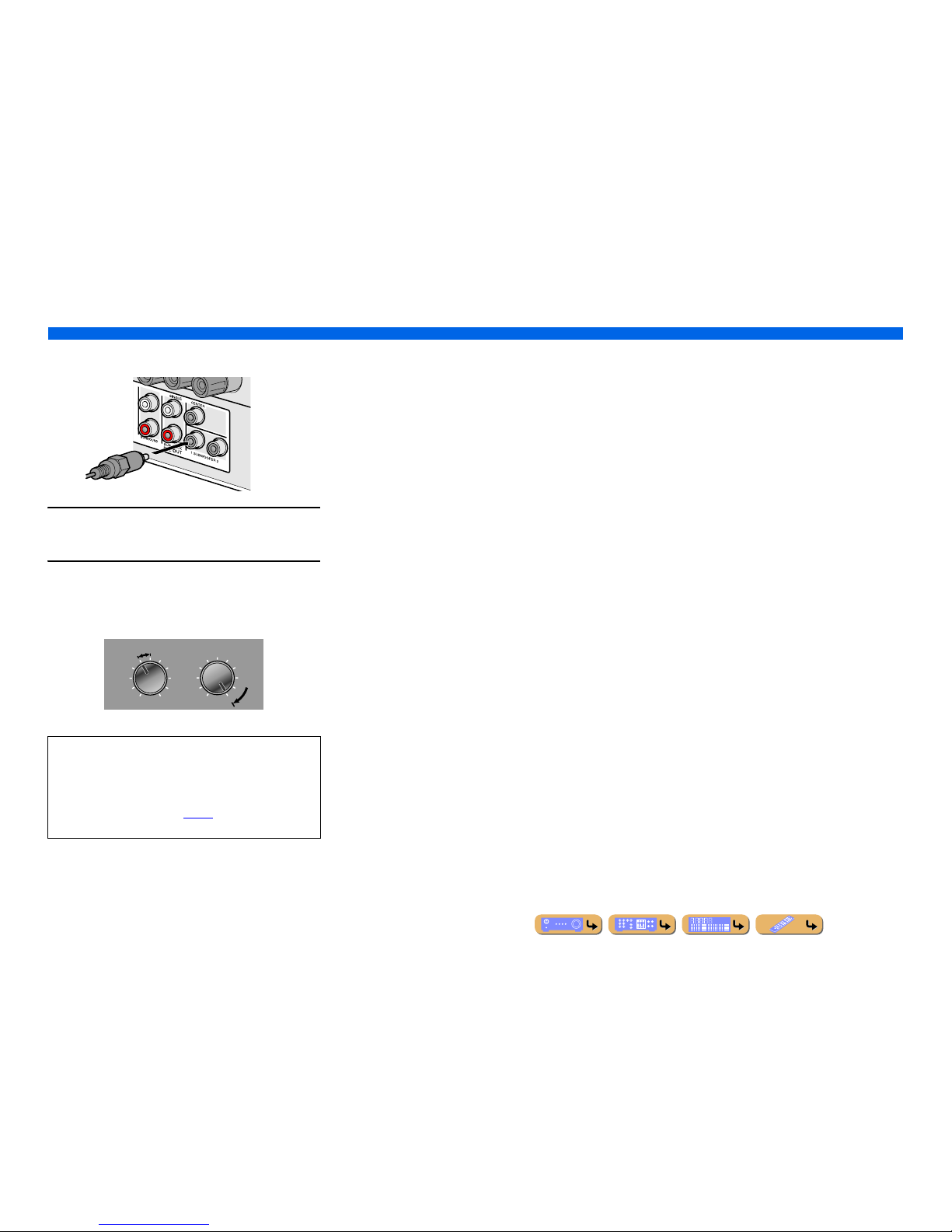
■
Connecting subwoofers
1
Connect the subwoofer input jack to the
SUBWOOFER 1 or 2 jack on this unit with an audio
pin cable.
2
Set the subwoofer volume as follows.
Volume: Set to approximately half volume (or slightly less than
half).
Crossover frequency (if available): Set to maximum.
NOTE
After connection, applying this setting to this unit is required to
activate all speaker connections. With using “Power Amp
Assign” function, you can easily apply the speaker
configuration.
Refer to “Power Amp Assign” (☞
p. 99) for details on using
“Power Amp Assign” function.
VOLUME
MIN MAX
CROSSOVER/
HIGH CUT
MIN MAX
Subwoofer examples
CONNECTIONS
En 21
Jacks and cables
This unit is equipped with the following input/output jacks. Use jacks and cables appropriate for
components that you are going to connect.
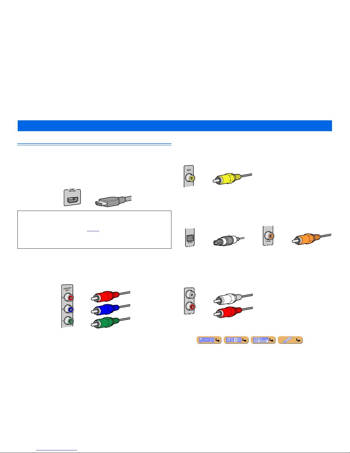
■
Audio/Video jacks
HDMI jacks
Digital video and digital sound are transmitted through a single jack.
Only use an HDMI cable.
■
Analog video jacks
■
Audio jacks
Connecting external components
• Use a 19-pin HDMI cable with the HDMI logo.
• We recommend using a cable less than 16.4 ft. (5.0 m) long to prevent signal quality degradation.
• When a TV that supports HDMI functions and Audio Return Channel function is connected, audio
output from the TV can be input to this unit (☞
p. 123).
• When a player and TV that support the 3D video format are connected to this unit, 3D content can be
played back.
• If you connect this unit to a component that has a DVI jack, an HDMI/DVI-D cable is required.
COMPONENT VIDEO jacks
The signal is separated into three components:
luminance (Y), chrominance blue (P
B), and chrominance red (PR).
Use component video pin cables with three plugs.
HDMI cable
Component video pin cable
VIDEO jacks
These jacks transmit conventional analog video
signals.
Use video pin cables.
OPTICAL jacks
These jacks transmit optical digital audio signals.
Use fiber-optic cables for optical digital audio
signals.
COAXIAL jacks
These jacks transmit coaxial digital audio signals.
Use pin cables for digital audio signals.
AUDIO jacks
These jacks transmit conventional analog audio
signals.
Use stereo pin cables, connecting the red plug to
the red R jack, and the white plug to the white L
jack.
Video pin cable
Digital audio fiber-optic cable
Digital audio pin cable
Stereo pin cable
CONNECTIONS
Connecting external components
En 22
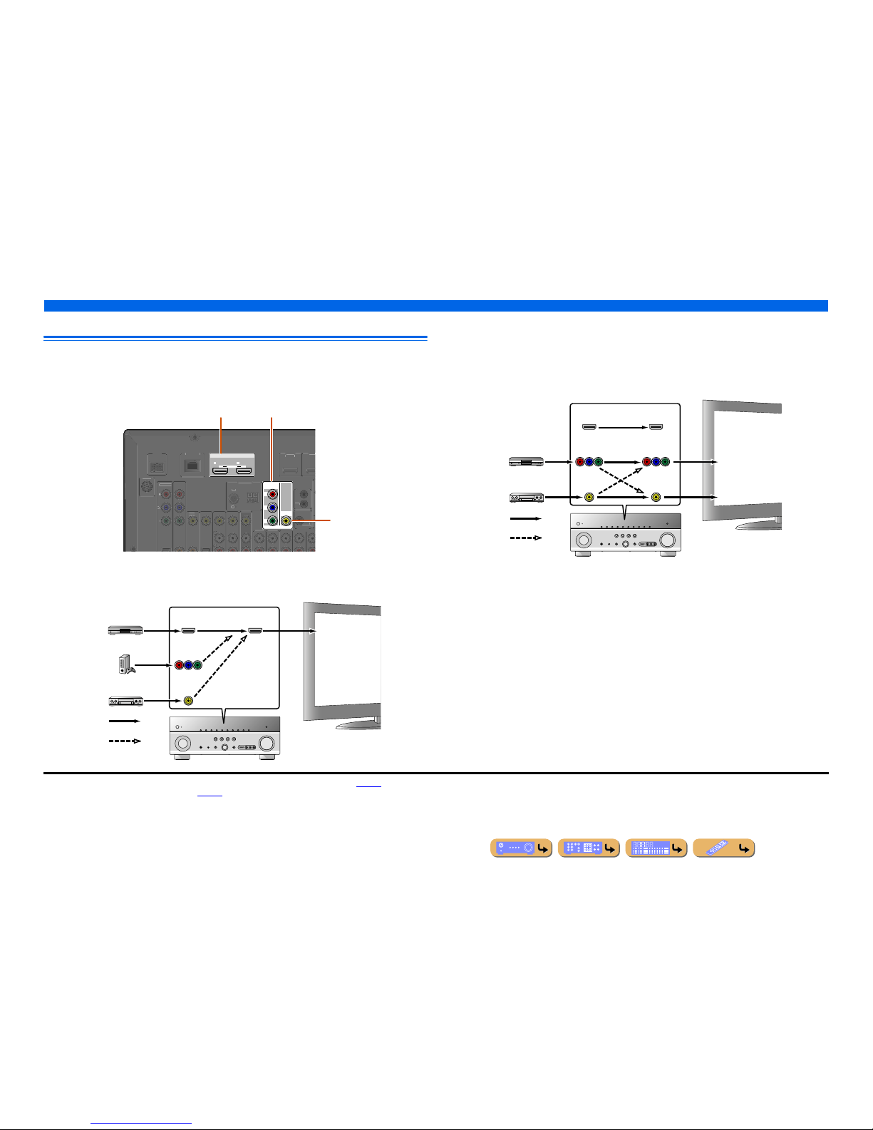
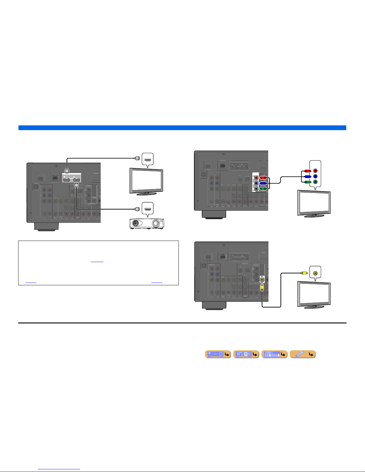
Connecting a TV monitor
This unit is equipped with the following three types of output jack for connection to a TV.
HDMI OUT 1-2, COMPONENT VIDEO or VIDEO. Select the proper connection according to the
input signal format supported by your TV.
When connecting to an HDMI compatible TV
Video signal such as component video and video received by this unit is converted to HDMI and output to
the TV. Just select HDMI input on the TV to view video from any external source connected to this unit. J1
When connecting to a non-HDMI compatible TV
Connect to the TV using the same type of connection that you used to connect to the external
component, and change the inputs on your TV to match that of the external component you are using
for playback. If the external component and TV are equipped with different types of analog video
jacks, this unit will convert the video signal to component video signal, or vice-versa, according to the
type of video input jacks used by the TV. J2, J3
HDMI OUT
12
ARC ARC
SELECTABLE
COMPONENT
VIDEO
VIDEO
MONITOR OUT
P
R
P
B
Y
D
OCK
VIDE
O
HDMI
1
(
BD/DVD
)
HDM
I
TRIGGER
OUT
+12V
0.1A MAX
.
IN
REMOTE
OUT
COMPONENT
VIDE
O
P
B
Y
SIRIUS
ANTENNA
F
M
75
G
NDAM
NETWORK
HDMI OUT 1-2 jacks
COMPONENT VIDEO jacks
(MONITOR OUT)
VIDEO jack
(MONITOR OUT)
HDMI
COMPONENT
VIDEO
HDMI
VIDEO
Input Output
HDMI input
Through
Converted
TV
COMPONENT
VIDEO
HDMI
VIDEO
COMPONENT
VIDEO
HDMI
VIDEO
Input Output
Video input
Through
Component
video input
TV
Converted
J
1 : You can change the resolution and aspect ratio when converting to HDMI to suit your requirements (☞p. 105).
J
2 : Set “Analog to Analog Conversion” to “On” (☞p. 104).
J
3 : Analog to analog conversion is available only for 480i/576i-resolution video signal.
CONNECTIONS
Connecting external components
En 23
■
Connecting an HDMI video monitor
Connect the HDMI cable to one of the HDMI OUT 1-2 jacks.
■
Connecting a component video monitor
Connect the component video cable to the COMPONENT VIDEO (MONITOR OUT) jacks.
■
Connecting a video monitor
Connect the video pin cable to the VIDEO (MONITOR OUT) jack.
• Use a 19-pin HDMI cable with the HDMI logo.
• We recommend using a cable less than 16.4 ft. (5.0 m) long to prevent signal quality degradation.
• When a TV that supports the HDMI function and Audio Return Channel function is connected, audio
output from the TV can be input to this unit (☞
p. 123).
• When a player and TV that support the 3D video format are connected to this unit, 3D content can be
played back.
• This unit is equipped with HDMI OUT 1 and 2 jacks. The active HDMI OUT jack(s) can be selected
(☞
p. 42). The active HDMI OUT jack(s) can be registered with the SCENE function (☞p. 44).
HDMI OUT
12
ARC ARC
SELECTABLE
DOCK
(
TV
)
AV 3
AV 4
AV 5
AV 6
AUDIO 1
AUDIO 2
MULT
(
C
D
)
CO
AXIAL
O
PTICAL
V
IDEO
(
BD/
DVD
)
AV
OUT
S
URRO
U
TRI
GG
FRON
T
IN
R
E
OUT
O
PTICA
L
AV 1
AV 2
CO
AXIA
L
COMPO
NEN
T
VIDE
O
P
B
Y
S
IRIU
S
COMPO
NENT
VIDE
O
VIDE
O
MONITOR OU
T
P
R
Y
FM
7
5
GND
AM
NETWORK
HDMI
HDMI
HDMI
HDMI
HDMI
HDMI
HDMI input
TV
Projector
J1
COMPONENT
VIDEO
P
R
P
B
Y
DOC
K
(
)
AV 3
AV 4
AV 5
AV 6
AUDIO 1
AUDIO 2
MULT
(
C
D
)
CO
AXIA
L
O
PTICA
L
V
IDE
O
(
BD/DVD
)
OUT
SURROU
TRIGG
FRO
NT
RE
O
UT
H
DMI OUT
ARCAR
C
S
ELECTABLE
OPTICA
L
AV 1
AV 2
CO
AXIAL
COMPO
NENT
V
IDE
O
S
IRI
US
V
IDE
O
R OUT
N
D
ETWOR
K
COMPONENT
VIDEO
Y
P
R
P
B
Y
P
R
P
B
Component video input
TV
J1
K
)
AUDIO 1
AUDIO 2
C
D
AXIA
L
PTICAL
V
IDE
O
BD/DVD
)
UT
RR
OU
TRIGG
FRON
T
R
E
UT
HDMI OU
T
2
A
RC ARCELECTABL
E
OPTICA
L
AXIA
L
MPONEN
T
V
IDE
O
IRI
US
OMPONEN
T
VIDE
O
NIT
O
B
N
D
ETWOR
K
VIDEO
V
V
Video input
TV
J
1 : When connecting to a TV that supports HDMI input, the video signal for the COMPONENT VIDEO or VIDEO jacks is
converted and output from HDMI OUT 1-2 jacks. When connecting to a TV via the HDMI jack, you do not need to use these
jacks.
En 24
CONNECTIONS
Connecting external components
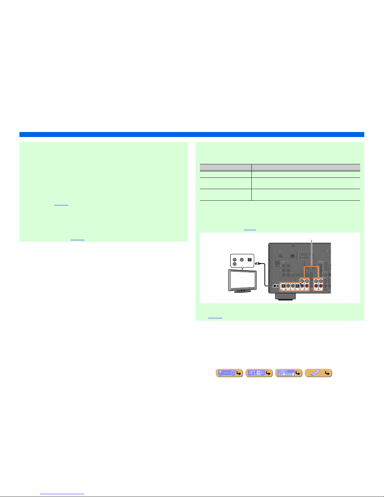
■ Listening to TV audio
To transmit sound from the TV to this unit, connect as followings according to the TV:
When using a TV that supports the Audio Return Channel function and HDMI
Control function
When your TV supports both HDMI Control (e.g., Panasonic VIERA Link) and Audio Return
Channel functions, audio/video output from the unit to the TV and audio output from the TV to the
unit are possible using a single HDMI cable.
The input source is switched automatically to match operations carried out on the TV, and that
makes TV sound control easier to use.
For the connections and settings, refer to “Single HDMI cable input to TV audio with Audio Return
Channel function” (☞
p. 123).
When using a TV that supports the HDMI Control functions
When using a TV that supports HDMI Control functions (e.g., Panasonic VIERA Link), if HDMI
Control functions are enabled on the unit, then input source can be switched automatically to match
operations carried out on the TV.
For the connections and settings, refer to “Switching the input source on this unit automatically
when listening to TV audio” (☞
p. 122).
When using other TVs
To transmit sound from the TV to this unit, connect AV1-6 or AUDIO1-2 jacks to the TV’s audio
output jacks.
Select the input source connected via TV’s audio output jack to enjoy the TV sound.
If the TV supports optical digital audio output, we recommend that you connect the TV audio output
to the receiver’s AV4 jack.
Connecting to AV4 allows you to switch the input source to AV4 with just a single key operation
using the SCENE function (☞
p. 44).
You can control your TV using the receiver’s remote control by entering the TV’s remote control
code (☞p. 116).
TV audio output Connection
Optical digital audio output Connect to the OPTICAL jack of the AV1 or AV 4 with a fiber-optic cable.
Coaxial digital audio output Connect to the COAXIAL jack of the AV2 or AV3 with a digital audio pin
cable.
Analog stereo output Connect to one of the AV5, AV6, AUDIO1, or AUDIO2 with a stereo pin
cable.
(
TV
)
AV
3
AV 4
AV 5
AV 6
AUDIO
1
AUDIO
2
(CD)
COAXIAL
OPTICAL
OPTICAL
AV 1
AV 2
COAXIAL
DOCK
V
IDE
O
DMI 1
D/DV
D
)
T
URR
OU
TRI
GG
FRONT
RE
DMI OU
T
ARC
ARC
S
ELECTABL
E
MPONENT
V
IDE
O
Y
SIRIU
S
COMPONENT
VIDE
O
V
IDE
O
MONITOR OUT
Y
N
D
AM
ETWOR
K
OPTICALCOAXIALAUDIO
Audio output
(Optical, coaxial, or analog)
TV
Available input jacks
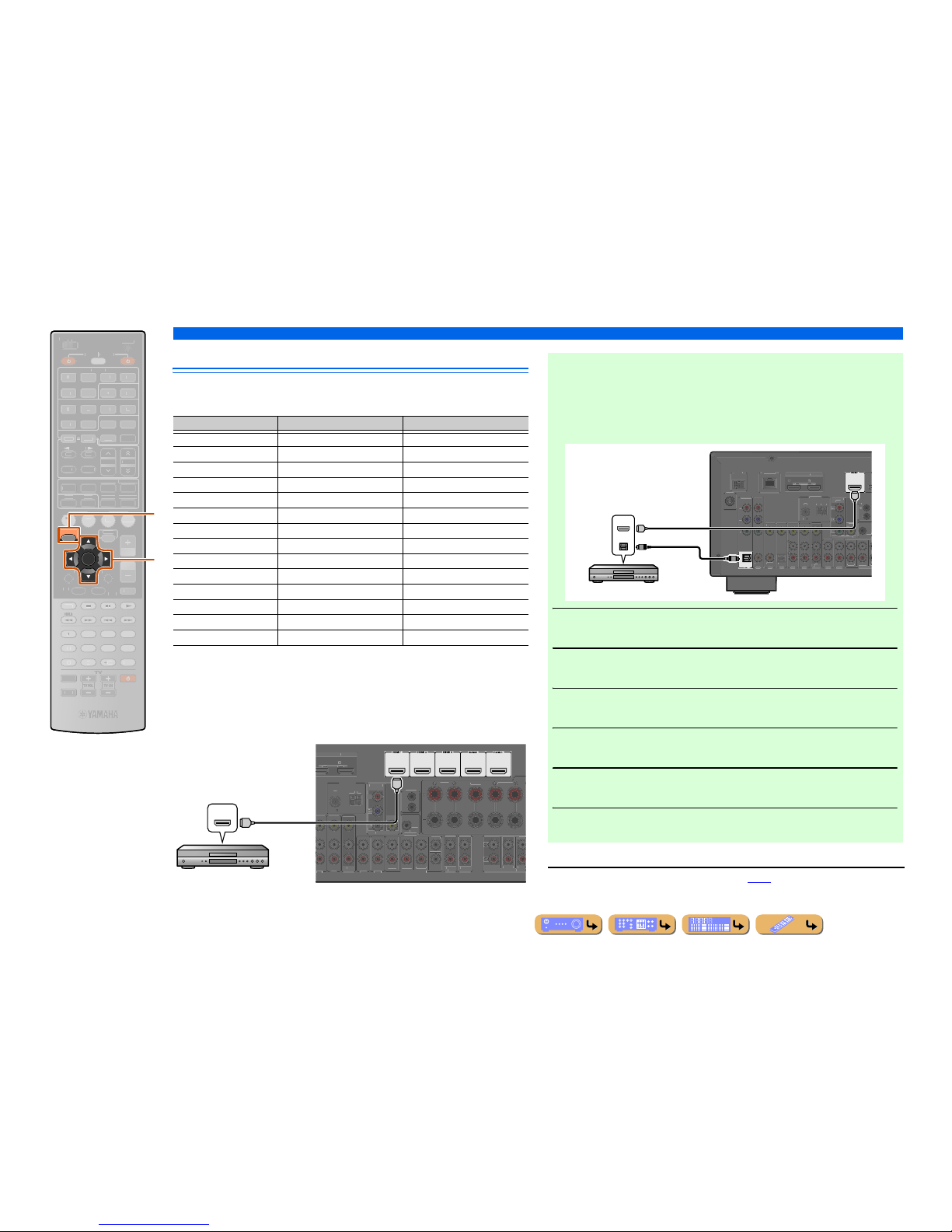
CONNECTIONS
Connecting external components
En 25
Connecting BD/DVD players and other devices
This unit has the following input jacks. Connect them to the appropriate output jacks on
the playback devices such as BD/DVD players.
■
Connecting BD/DVD players and other devices with
HDMI
Connect the device with an HDMI cable to one of the HDMI1-5 jacks. The HDMI IN
jack on the front panel can also be used.
Select the HDMI input (HDMI1-5 or VIDEO AUX) that the playback device is
connected to for playback.
ENTER
ON SCREEN
SCENE
LUME
ENHANCE
R
UR. DECODE
STRAIGHTSLEEP
URE DIRECT
OVIEUSI
C
RADI
O
MUT
E
EC
NFOEMORY
RESET
DMI
UDI
O
-
AUX
TOP
OP-U
P
EN
U
DISPLAY
URCE
AIN
ZONE 2
RECEIVE
R
CODE SE
T
NPUT
DOCK
HDMI OU
T
PTION
NET
IRI
US
TU
NER
TUN./C
H
ATEGOR
Y
k
j
jON SCREEN
kCu rsor B / C / D / E
kENTER
Input Video input Audio input
HDMI1 HDMI HDMI
HDMI2 HDMI HDMI
HDMI3 HDMI HDMI
HDMI4 HDMI HDMI
HDMI5 HDMI HDMI
AV1 Component video Optical digital
AV2 Component video Coaxial digital
AV3 Video Coaxial digital
AV4 Video Optical digital
AV5 Video Analog (Stereo)
AV6 Video Analog (Stereo)
AUDIO1 — Analog (Stereo)
AUDIO2 — Analog (Stereo)
VIDEO AUX HDMI/Video HDMI/Analog (Stereo)
(
BD/DVD
)
AUDIO 1
AUDIO 2
ENTER
SURROUN
D
RONT
V
T
UBWOOFE
R
DIONE
2
T
UR.BACKURROUND
URROUNDSUR.BA
C
RE
OU
FRONT
T
RIGGER OUT
+12
V
.1A
MAX.
FRON
T
CENTER
REMOTE
T
INGL
E
DMI OUT
AR
C
ARC
ELECTABLE
MPONEN
T
VIDE
O
V
IDE
O
NITOR OUT
NTENN
A
ND
HDMI
HDMI
HDMI
HDMI output
BD/DVD player
■ Receiving video signals from the HDMI jack and audio signals
from a jack other than HDMI
This unit can use the AV1-6 or AUDIO1-2 input jacks to receive audio signals from
other input jacks.
For example, if a playback device cannot produce audio signals from an HDMI jack,
use the following method to change the audio input.
1
Press jON SCREEN to display the ON SCREEN menu.
2
Press kCursor B / C repeatedly to select “Input,” and then press
kENTER. J1
3
Press kCursor D / E repeatedly to select the desired HDMI input
source, and then press kCursor B.
4
Press kCursor C repeatedly to select “Audio In,” and then press k
ENTER.
5
Press kCursor B / C to select the audio input source.
6
Once you have completed the setup, press jON SCREEN to close
the menu.
J
1 : Refer to the “Configuring input sources (Input menu)” (☞p. 86) for details on selecting the input source.
(
BD/DVD
)
OPTICAL
TV
)
AV 3
AV 5
AV 6
AUD
IO
1
AUD
IO
2
(
)
COAXIA
L
OPTICAL
V
IDE
O
T
RROUN
D
TRIGGER OU
T
.1A MA
X
FRONT
I
N
DMI OUT
ARC
ARC
S
ELECTABL
E
AV 2
AXIAL
MPONENT
V
IDE
O
R
Y
IRIU
S
COMPONENT
V
IDE
O
V
IDE
O
NITOR OU
T
Y
M
N
D
AM
ETWOR
K
HDMI
OPTICAL
HDMI
HDMI
O
O
HDMI/Audio (Optical)
output
BD/DVD player
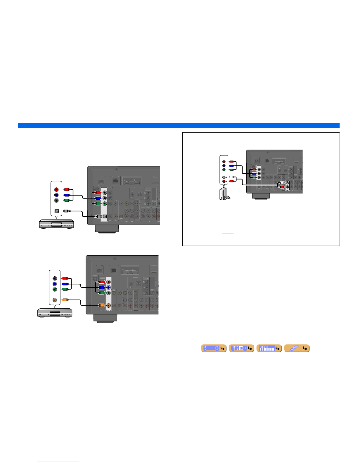
En 26
CONNECTIONS
Connecting external components
■
Connecting BD/DVD players and other devices with component
video cables
Connect the device with a component video cable to one of the AV1-2 input jacks.
Using optical digital audio output sources
Select the AV1 input to which the playback device is connected for playback.
Using coaxial digital audio output sources
Select the AV2 input to which the playback device is connected for playback.
OPTICAL
COMPONENT
VIDEO
P
R
P
B
Y
)
AUDIO 1
AUDIO 2
D
)
AXIA
L
PTICA
L
VIDE
O
D/DV
D
OU
T
RR
OU
TRIGG
RONT
U
T
HDMI
OUT
ARCARC
ELECTABL
E
AXIAL
IRI
US
OMPONEN
T
V
IDEO
V
IDE
O
MONITOR OU
T
P
ND
NETWORK
COMPONENT
Y
P
R
P
B
Y
P
R
P
B
O
OPTICAL
O
Component video / Audio (Optical)
output
BD/DVD player
COAXIAL
K
)
AUDIO 1
AUDIO 2
C
D
)
AXIA
L
PTICAL
V
IDE
O
BD/DVD
)
OUT
RR
OU
TRIGG
FRON
T
R
E
UT
HDMI
OUT
ARCARC
ELECTABL
E
OPTICA
L
MPONEN
T
V
IDE
O
IRI
US
OMPONENT
VIDE
O
VIDE
O
NITOR OUT
B
N
D
ETWOR
K
COMPONENT
VIDEO
COAXIAL
Y
P
R
C
P
B
Y
P
R
P
B
C
Component video / Audio (Coaxial)
output
BD/DVD player
■ Component connections to analog audio output devices
The video input from the AV1-2 jacks can be used in combination with the audio input from other
AV inputs or AUDIO1-2.
When connecting these devices, select the AV input jacks or the AUDIO1-2 jacks as the audio input
for AV1 or AV2. Refer to “Receiving video signals from the HDMI jack and audio signals from a
jack other than HDMI” (☞
p. 25) for detailed setup guidance.
For playback of the connected device, select the AV input source (AV1-2) to which the device is
connected with the component video cable.
COMPONENT
VIDEO
P
R
P
B
Y
D
OCK
)
A
V
3
A
V
A
V
5
A
V
6
AUD
IO 2
ULTI CH
IN
D
)
COAXIA
L
PTICA
L
VIDE
O
D/DV
D
)
SUSURROUND
TRIGGER OUT
+12V
.1A
MAX
RON
T
N
DMI
OUT
1
ARCAR
C
S
ELECTABLE
PTICA
L
A
V
1
A
V
2
AXIA
L
IRI
US
MPONEN
T
V
IDE
O
VIDE
O
NITOR
OUT
R
ANTENNA
ND
ETWORK
AUDIO
COMPONENT
VIDEO
R
L
R
L
Y
P
R
P
B
Y
P
R
P
B
Component video / Audio
output
Game console
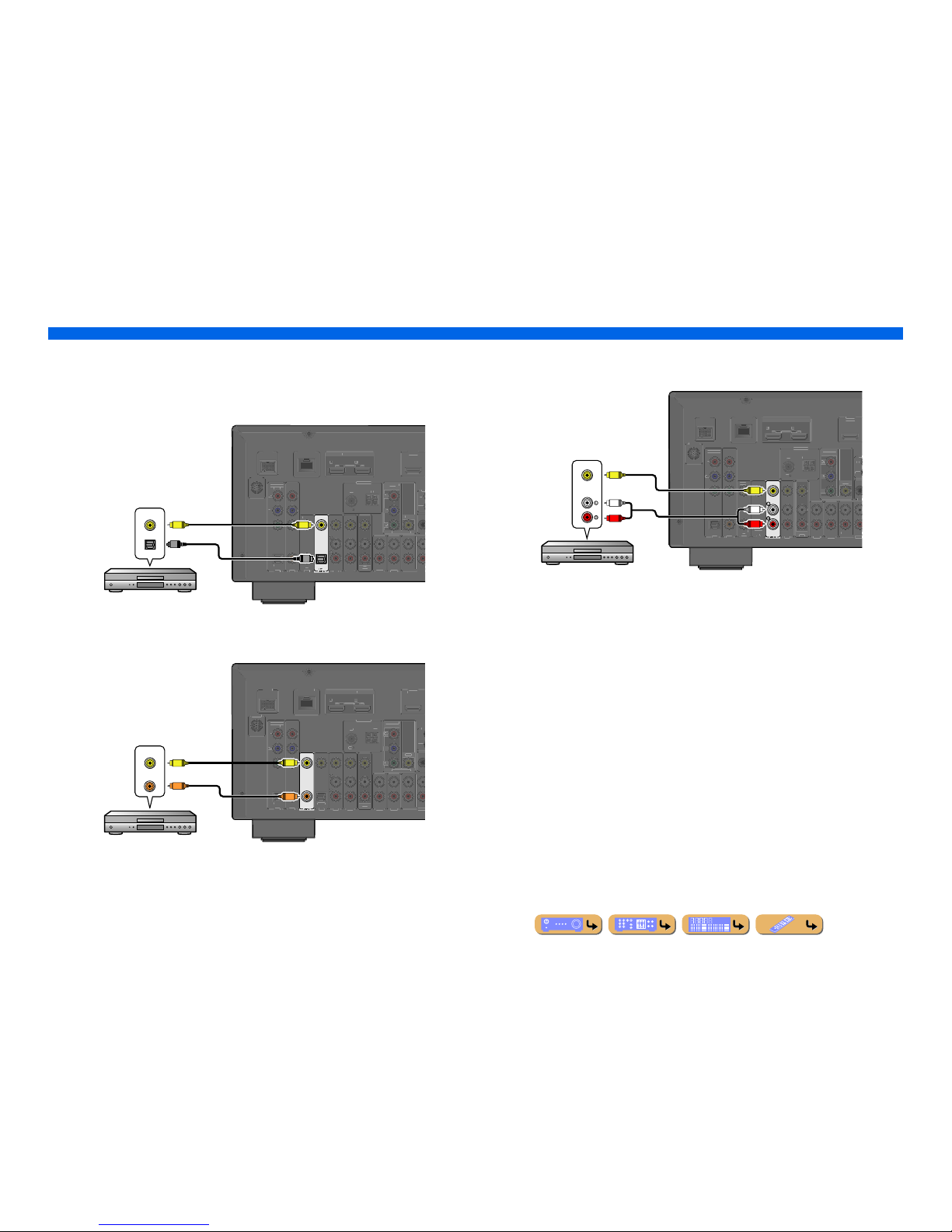
En 27
CONNECTIONS
Connecting external components
■
Connecting BD/DVD players and other devices with video cables
Connect the playback device with a video pin cable to one of the AV3-6 input jacks.
Using optical digital audio output sources
Select the AV4 input to which the playback device is connected for playback.
Using coaxial digital audio output sources
Select the AV3 input to which the playback device is connected for playback.
Using analog stereo audio output sources
Select the AV5 or AV6 input to which the playback device is connected for playback.
OPTICAL
AUDIO 1
AUDIO 2
(
D
)
AXIA
L
VIDE
O
D/DV
D
OU
T
RR
OU
TRI
GG
RONT
U
T
DMI OUT
ARCARC
SELECTABLE
PTICAL
AXIAL
MPONENT
VIDE
O
IRI
US
OMPONEN
T
V
IDEO
V
IDE
O
MONITOR OU
T
P
ND
NETWORK
VIDEO
OPTICAL
V
V
O
O
Video / Audio (Optical)
output
BD/DVD player
(CD)
COAXIAL
VIDEO
DOCK
)
AUDIO 1
AUDIO 2
PTICAL
BD/DVD
)
UT
RR
OU
TRIGG
FRON
T
R
E
UT
DMI OUT
ARCARCELECTABLE
OPTICA
L
AXIA
L
MPONEN
T
V
IDE
O
IRI
US
COMPONENT
VIDE
O
VIDE
O
NITOR OUT
N
D
NETWORK
VIDEO
COAXIAL
V
V
C
C
Video / Audio (Coaxial)
output
BD/DVD player
DOCK
)
AUDIO 1
AUDIO 2
D
)
AXIAL
PTICAL
V
IDE
O
D/DVD
)
UT
RR
OU
TRI
GG
FRON
T
R
E
UT
DMI OUT
1 2
ARCARCELECTABLE
OPTICA
L
AXIA
L
MPONEN
T
V
IDE
O
IRI
US
COMPONENT
VIDE
O
VIDE
O
NITOR OUT
N
D
NETWORK
AUDIO
VIDEO
R
L
R
L
V
V
Video / Audio
output
BD/DVD player
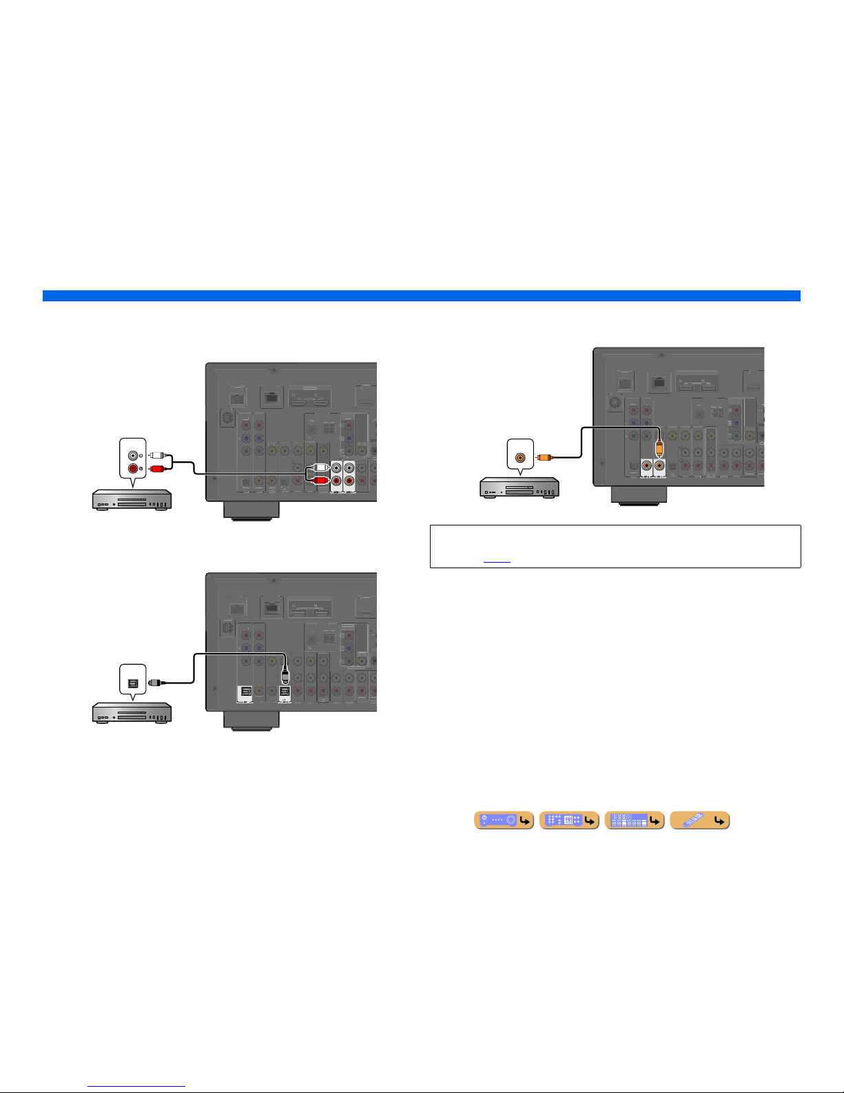
En 28
CONNECTIONS
Connecting external components
■
Connecting CD players and other audio devices
Using analog stereo output sources
Select the audio input (AUDIO1-2) to which the playback device is connected for playback.
Using optical digital output sources
Select the AV input (AV1 or AV4) to which the playback device is connected for playback.
Using coaxial digital output sources
Select the AV input (AV2 or AV3) to which the playback device is connected for playback.
DOCK
)
C
D
AXIAL
PTICAL
V
IDE
O
BD/DVD
)
UT
RR
OU
TRIGG
FRON
T
R
E
UT
DMI OUT
ARCARCELECTABLE
OPTICA
L
AXIA
L
MPONEN
T
V
IDE
O
IRI
US
COMPONENT
VIDE
O
VIDE
O
NITOR OUT
N
D
ETWORK
AUDIO
R
L
R
L
Audio output
CD player
OPTICAL
OPTICAL
DOCK
AUDIO 1
AUDIO 2
C
D
AXIAL
V
IDE
O
BD/DVD
)
UT
RR
OU
TRIGG
FRON
T
R
E
UT
HDMI
OUT
ARCARC
ELECTABL
E
AXIA
L
MPONEN
T
V
IDE
O
IRI
US
COMPONENT
VIDE
O
VIDE
O
NITOR OUT
N
D
ETWORK
O
O
OPTICAL
CD player
Audio (Optical) output
We recommend connecting audio devices with a coaxial digital output to the AV3 coaxial digital
jack on this unit. This connection allows you to switch to the AV input 3 just by pressing the “CD”
SCENE key (☞
p. 44).
(CD)
COAXIAL
COAXIAL
DOCK
)
AUDIO 1
AUDIO 2
PTICAL
V
IDE
O
BD/DVD
)
UT
RR
OU
TRIGG
FRON
T
R
E
UT
DMI OUT
AR
C
ARC
ELECTABLE
OPTICA
L
MPONEN
T
V
IDE
O
IRI
US
COMPONENT
VIDE
O
VIDE
O
NITOR OUT
N
D
ETWORK
C
C
COAXIAL
Audio (Coaxial) output
CD player
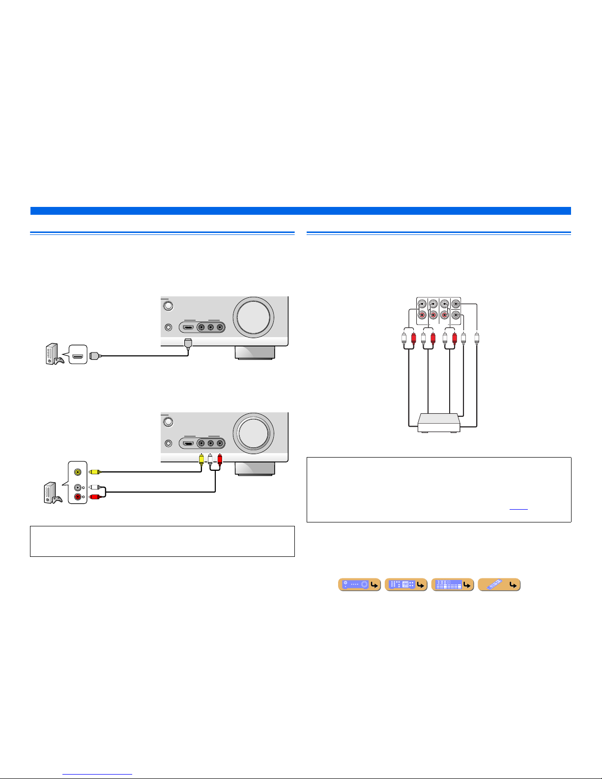
En 29
CONNECTIONS
Connecting external components
Connecting game consoles
Use the VIDEO AUX jacks on the front panel to temporarily connect devices such as a game console to
the receiver.
Select the V-AUX input to use these connected devices.
■
When connecting an HDMI compatible device
Connect the HDMI output of the device to the HDMI IN jack of this unit.
■
When connecting an non-HDMI compatible device
Connect the video and audio outputs of the device to the VIDEO and AUDIO jacks of this unit.
Connecting a multi-format player or an external decoder
This unit has 8 sets of input jacks (FRONT L/R, CENTER, SURROUND L/R, SUR. BACK L/R and
SUBWOOFER) to input multi-channel analog sound signals. If your playback component, such as a
DVD player or SACD player, has multi-channel analog output capability, you can enjoy up to 7.1channel multi-channel sound. To output multi-channel sound, connect the audio output jacks of your
playback component to the MULTI CH INPUT jacks of this unit, and set the input source of this unit to
“MULTI CH.”
• Be sure to turn down the volume when connecting this unit and the other devices.
• When both the HDMI connection and the analog video/audio connection are performed between the
HDMI compatible device and this unit, only the HDMI signal will be input.
VIDEO
AUX
STRAIGHT
RADIO
VIDEO
AUDIO
HDMI IN
LR
HDMI
HDMI
HDMI
HDMI output
Game console
VIDEO
AUX
STRAIGHT
RADIO
VIDEO
AUDIO
HDMI IN
LR
AUDIO
VIDEO
R
L
VVRL
Video output
Analog audio output
Game console
• When you select “MULTI CH” as the input source, the digital sound field processor and tone control are
automatically disabled.
• Since this unit does not redirect signals input at the MULTI CH INPUT jacks to accommodate for
missing speakers, connect at least a 5.1-channel speaker system when using this feature.
• When the input source is switched to “MULTI CH,” images input from a component connected to the
HDMI1-5, AV1-6, or VIDEO AUX jacks can be displayed on a video monitor (☞
p. 89). If your DVD
player does not support multi-channel digital output, connect it to these input jacks.
M
UL
TI CH INPUT
SUBWOOFER
SUR.BACK
SURROUND
FRONT
CENTER
RL RL RL
Surround out
Front out
Subwoofer out
Center out
Multi-format player/External decoder
(7.1-channel output)
Surround back out
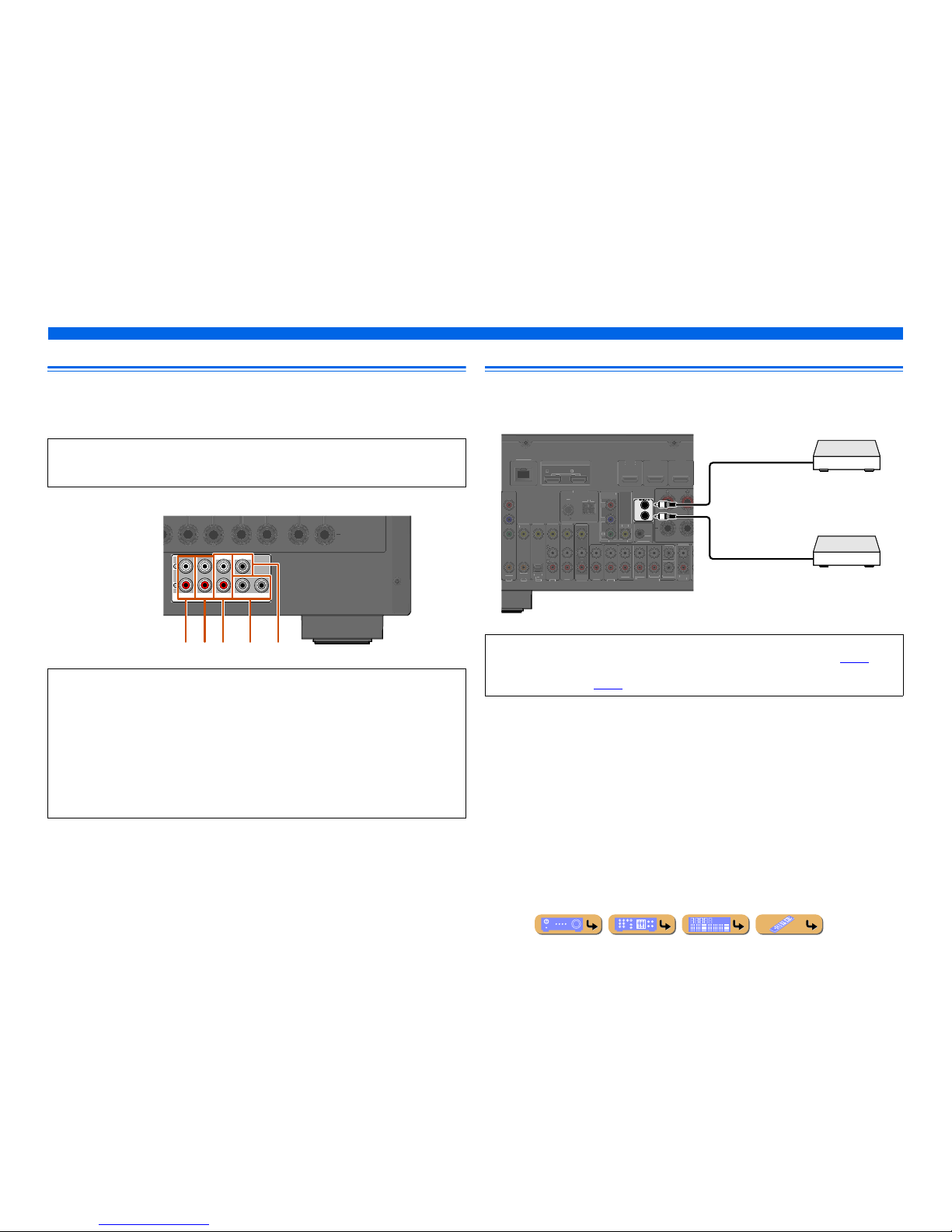
En 30
CONNECTIONS
Connecting external components
Connecting an external amplifier
The same channel signals are output from the jacks of the PRE OUT terminals as from their
corresponding SPEAKERS terminals. When connecting an external power amplifier (pre-main
amplifier) to enhance speaker output, connect the input terminals of the power amplifier to the PRE
OUT terminals of this unit.
Connecting a SCENE link playback-compatible device
When the components are the Yamaha products and have the capability of the transmission of the
remote control signals, connect the REMOTE IN and REMOTE OUT jacks to the remote control input
and output jack with the monaural analog mini cable as follows.
NOTE
When a component is connected to the PRE OUT terminals, do not connect speakers to the
SPEAKERS terminals corresponding to those PRE OUT terminals.
a FRONT (PRE OUT) jacks
Front channel output jacks.
b SURROUND (PRE OUT) jacks
Surround channel output jacks.
c SUR. BACK (PRE OUT) jacks
Surround back output jacks. When you only co nnect one external amplifier for the surround back channel,
connect it to the SUR. BACK (SINGLE) jack.
d SUBWOOFER (PRE OUT) 1/2 jack
Connect a subwoofer with a built-in amplifier. When two subwoofers are connected, the same sound is
output from them.
e CENTER (PRE OUT) jack
Center channel output jack.
SURROUND
SUR.BACK
PRE OUT
SUBWOOFER12
FRONT
CENTERSINGLE
abc d e
• When a Yamaha component that supports the SCENE link playback function is connected via the
REMOTE OUT jack, playback begins automatically when the SCENE function is used (☞
p. 44).
• If the component connected to the REMOTE OUT jack is not a Yamaha product, set “SCENE IR” in the
SCENE menu to “Off” (☞
p. 91).
IN
OUT
TV
)
AUDIO 1
AUDIO 2
D
)
AXIAL
OPTICA
L
VIDEO
D/DV
D
3
FRON
T
A
V
BWOOFER
AUDI
O
OUT
SUR.BACK
URROUN
D
TRIGGER
OUT
12V
.1A MAX.
FRON
T
ENTE
R
HDMI OU
T
ARC
ARC
SELECTABL
E
AXIA
L
MPONENT
V
IDE
O
VIDE
O
MONITOR OU
T
Y
FM
7
5
NDM
NETWORK
Remote control out
Remote control in
Infrared signal receiver or
Yamaha component
Yamaha component
(CD or DVD player, etc.)
 Loading...