

Page 1

OWNER'S MANUAL
Page 2
CAUTION
RISKOFELECTRICSHOCK
DONOTOPEN
CAUTION: TO REDUCE THE RISK OF
ELECTRIC SHOCK, DO NOT REMOVE
COVER (OR BACK). NO USER-SERVICEABLE
PARTS INSIDE. REFER SERVICING TO
QUALIFIED SERVICE PERSONNEL.
• Explanation of Graphical Symbols
The lighming flash with arrowhead symboh within an
equilateral triangle, is inlended 1o alert you to the
prescnce of uninsulated 'dangerous voltage" wilhin
lhe producl_s enclosure lhal may be of sutlicient
magnitude to conslitute a risk of electric shock to
persons.
The exclamation point within an equilateral triangle
is intcnded m alert you to tile presence of important
operating and maintenance (smwicing) instructkms in
the literature accompanying the appliance.
1 Read Instructions All the sali:ty attd operating instructions
should be read before the product is operated.
2 Retain Instructions The safety and operating instructions
should be retained lk_rluture rel-erence.
3 Heed W:_rtfings All warnings on the product and in the
operating instructions should be adhered to.
4 Follow Instructions All operating and use instructions
should be l_llowed.
5 Cleaning Unplug this product from the wall outlet belore
cleaning. Do not use liquid cleaners or aerosol cleatmrs.
6 Attachments Do not use attachments not recommended by
the product manulhcmrer as they may cause hazards.
7 Water aud Moisture Do not use this product near water
for example, near a bath tub. wash bowl. kitchen sink. or
hmndry tub: in a wet basement: or near a swimming pooh
and the like.
8 Accessories Do not place this product on an unstable cart.
stand, tripod, bracket, or table. The product may lall.
causing serious it_iury to a child or adult, and serious
damage to the product. Use only with acart. stand, tripod,
bracket, or table recommended by the manulhcturer, or sold
with the product. Any tnountit_g of the product should
follow the manufi_cmrer's instructions, and should use a
mt)unting accessory recommended by the manufacturer.
9 A product and cart combination should be tnoved with care.
Quick stops, excessive lbrce, and uneven surlaces may
cause the product and cart combination to
overturn.
10 Ventilation Slots and openings in the cabitmt are provided
lk_rventilation and to ensure reliable operation of the
product and to protect it from overheating, and these
openings must not be blocked or covered. The opetfings
should never be blocked by placing the product on a bed.
sofa. rug, or other similar surface. This product should not
be placed in a built-in installation such as a bookcase or rack
unless proper ventilation is provided or the manufacturer's
instructions haxe been adhered to.
11 Power Sources This product should be operated only from
the type of power source indicated on the marking label. If
you are not sure of the type of power supply to your home.
consult your product dealer or local power company. For
products intended to operate li'om battery power, or other
sources, refer to the operating instructions.
12 Groundit_g or Polarization This product may be equipped
with a polarized alternating current line plug (a plug having
one blade wider than the other). This plug will fit into the
power outlet only one way. This is a sali:ty ligature. If you
are unable to insert the plug fully into the outlet, try
reversing the plug. If the plug should still lail to fit. contact
your electrician to replace your obsolete outlet. Do not
defeat the salhty purpose of the polarized plug.
13 Power-Cord Protection Power-supply cords should be
routed so that they are not likely to be walked on or pinched
by items placed upon or against them, paying particular
attention to cords at plugs, convenience receptacles, and the
point where they exit from the product.
14 Lightning For added protection for this product during a
lightning storm, or when it is left unattended and utmsed liar
long periods of time. unplug it from the wall outlet and
discotmect the antetma or cable system. This will prevent
damage to the product due to lightning and povcer-line
sLirges.
15 Power Lines An outside antetma system should not be
located in the vicinity of overhead power lines or other
electric light or power circuits, or where it can lall into such
power lines or circuits. When installing an outside antenna
system, extreme care should be taken to keep from touching
such power lines or circuits as contact with them might be
fatah
16 Overloading Do not overload wall outlets, extension
cords, or integral convenience receptacles as this can result
in a risk of fire or electric shock.
17 Ot_ject and Liquid Entry Never push ohjects of any kind
into this product through openings as they may touch
dangerous voltage points or short-out parts that could result
in a fire or electric shock. Never spill liquid of any kind on
the product.
18 Servicing Do not attempt to service this product yourself
as opening or removing covers may expose you to
dangerous voltage or other hazards. Refer all servicing to
quali fled service personneh
19 Damage Requiring Service Unplug this product from the
wall outlet and refer servicing to qualified service personnel
under the following conditions:
a) When the power-supply cord or plug is damaged,
b) If liquid has been spilled, or ot_iects haxe lallen into the
product.
c) If the product has been exposed to rain or water.
Caution-i En
Page 3
d) If the product does not operate normally by following 24
the operating instructions. Adjust only those controls
that are covered by the operating instructions as an
improper adjustment of other controls may result in
damage and will often require extensive work by a
qualified technician to restore the product to its normal
operation.
e) If the product has been dropped or damaged in any
way, and
f) When the product exhibits a distinct change in perfor-
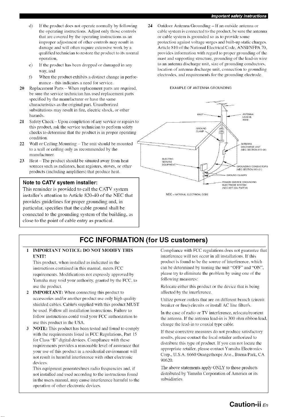
Outdoor Antenna Grounding If an outside antenna or
cable system is connected to the product, be sure the antmma
or cable system is grounded so as to provide some
protection against voltage surges and built-up static charges.
Article 810 of the National Electrical Code. ANSI/NFPA 70.
provides information with regard to proper grounding of the
mast and supporting structure, grounding of the leadqn wire
to an antmma discharge unit. size of grounding conductors.
location of autelma discharge unit. connection to grounding
electrodes, and requirements for the grounding electrode.
mance - this indicates a need for service.
20 Replacement Parts When replacement parts are required.
EXAMPLE OF ANTENNA GROUNDING
be sure the service technician has used replacement parts
specified by the mauulhctarer or haxe the same
characteristics as the original part. Unauthorized
substitutions may result in fire. electric shock, or other
hazards.
21 Safety Check Upon completion of any service or repairs to
this product, ask Ihe service lechuician 1(7perform safety /-/
checks Io determine Ihal Ihe producl is in proper operating /
condition. /
22 W:dl or Ceiling Mounting The unit should be mounted
to a wall or ceiling only as recommended by the
manufacturer.
23 Heat The product should be situated away lrom heal SERWCe
ELECTRIC
sources such as radiators, heat registers, stoves, or other
products (including amplifiers) that produce heat.
(NEC SECTION 810_0)
(NEC SECTION 810_1)
Note to CATV system installer:
This reminder is provided to call the CATV system
installer's attention to Article 820-40 of the NEC that
provides guidelines for proper grounding and, in
particular, specifies that the cable ground shall be
connected to the grounding system of the building, as
close to the point of cable entry as practical.
FCC INFORMATION (for US customers)
1 IMPORTANT NOTI(E: DO NOT MODIFY THIS
UNIT!
This product, when installed as indicated in the
instructions contained in this manual, meets FCC
requiremmlts. Modifications not expressly approved by
Yamaha may void your authority, granted by the FCC. to
use the product.
IMPORTANT: When connecting this product to
accessories and/or another product use only high quality
shielded cables. Cahle/s supplied with this product MUST
be used. Follow all installation instructions. Failure to
folh)w instructions could void your FCC authorization to
use this product in the USA.
NOTE: This product has been tested and found to comply
with the requirements listed in FCC Regulations. Part 15
for Class "B" digital devices. Compliance with these
requirements provides a reasonable level of assurance that
your use of this product in a residential mwiroument will
not result in harmful interlhrence with other electronic
devices.
This equipment generates/uses radio frequencies and. if
not installed and used according to the instructions round
in the users manual, may cause interli_rence harmful to the
operation of other electronic devices.
ELECTRODE SYSTEM
(NEC ART25O PARTH)
NEC NATIONAL ELECTRICALCODE
Compliance with FCC regulations does not guarantee that
interference will not occur in all installations. If this
product is louud to he the source of interferm/ce, which
can be determined by turning the unit "OFF" and "ON".
please try to eliminate the problem by using one of the
following measures:
Relocate either this product or the device that is being
aflhcted by the interference.
Utilize power outlets that are on different branch (circuit
breaker or fllse) circuits or install AC line filter/s.
In the case of radio or TV interlerence, relocate/reorient
the antenna. If the antenna lead-in is 300 ohm ribbon lead.
change the leadqn to coaxial type cable.
If these corrective measures do not produce satisfactory
results, please contact the local retailer authorized to
distribute this type of product. If you can not locate the
appropriate retailer, please contact Yamaha Electronics
Corp.. U.S.A. 6660 Orangethorpe Ave.. Buena Park. CA
90620.
The above statements apply" ONLY to those products
distributed by Yamaha Corporation of America or its
subsidiaries.
Caution-ii En
Page 4
1 To assure the finest performance, please read this manual
carefully. Keep it in a sali_ place for future reli_rence.
2 Install this sound system in a well ventilated, cool. dry, clean
place away from direct sunlight, heat sources, vibration.
dust. moisture, and/or cold. Allow ventilation space of at least
30 cm on the top, 20 cm on the left and right, and 2(1cm on
the back of this unit.
3 Locate this unit away lrom other electrical appliances, motors.
or transformers to avoid hunlmiug souuds.
4 Do not expose this unit to sudden temperature changes l?om
cold to hot. and do not locate this unit in an environment with
high humidity (i.e. a room with a humidifier) to prevent
condensation inside this unit. which may cause an electrical
shock, fire. damage to this unit. aud/or personal injury.
5 Avoid installing this unit where foreign objects may lall onto
this unit and/or this unit may be exposed to liquid dripping or
splashing. On the top of this unit. do not place:
other components, as they may cause damage aud/or
discoloration on the surface of this unit.
burning objects (i.e. candles), as they may cause fire.
damage to this unit. and/or personal injury.
containers with liquid in thmn. as they may f:dl and liqukl
may cause electrical shock to the user and/or damage to
this unit.
6 Do not cover this unit with a newspaper, tablecloth, curtain.
etc. in order not to obstruct heat radiation. If the temperature
inside this unit rises, it may cause fre. damage to this unit.
and/or personal il_jury.
7 Do not plug in this unit to a wall outlet until all connections
are complete.
8 Do not operate this unit upside-down. It may overheat.
possibly causing damage.
9 Do not use force on switches, knobs antVor cords.
10 When discmmecting the power cable from the wall outlet.
grasp the plug; do not pull the cable.
11 Do not clean this unit with chemical solvents: this might
damage the finish. Use a clean, dry cloth.
12 Only voltage specified on this unit must be used. Using this
unit with a higher voltage than specified is dangerous and may
cause lire, damage to this unit. and/or personal injury. Yamaha
will not be held responsible lk_rany damage resulting from use
of this unit with a voltage other than specified.
13 To prevent damage by lightning, keep the power cord and
outdoor antennas disconnected from a wall outlet or the unit
during a lightning storm.
14 Do not attempt to modil} or fix this unit. Contact qualified
Yamaha service persomlel when any service is needed. The
cabinet should never be opened lot any reasons.
IS When not plamfiug to use this unit lor long periods of time
(i.e. vacation), disconnect the AC power plug l?om the wall
outlet.
16 Install this unit near the AC outlet and where the AC power
plug can be reached easily.
17 Be sure to read the "Troubleshooting" section on common
operating errors belbre concluding that this unit is l:mlty.
18 Before moving this unit, press MASTER ON/OFF to release it
outward to the OFF position to turn off this unit. and then
disconnect the AC power plug from the AC wall outlet.
19 VOLTAGE SELECTOR (Asia and General models only)
The VOLTAGE SELECTOR on the rear panel of this unit
must be set for your local main voltage BEFORE plugging
into the AC wall outlet. Voltages are:
Asia model ............................ 22t)/230 241)V AC. 50/60 Hz
General model ........ 110/120/220/230 240 V AC. 51)/60 Hz
20 The balteries shall not be exposed to excessive heat such its
sunshine, fire or like.
WARNING
TO REDUCE THE RISK OF FIRE OR ELECTRIC
SHOCK, DO NOT EXPOSE THIS UNIT TO RAIN
OR MOISTURE.
As long as this unit is connected to the AC wall outlet,
it is not disconnected from the AC power source even
if you turn off this unit by MASTER ON/OFF. In this
state, this unit is designed to consume a very small
quantity of power.
FOR CANADIAN CUSTOMERS
To prevent electric shock, match wide blade of ping to
wide slot and tully insert.
This Class B digital apparatus complies with Canadian
ICES-003.
POUR LES CONSOMMATEURS CANADIENS
Pour (viter les chocs (lectriques, introduire la htme la
plus large de la fiche dans la borne correspondante de
la prise et pousser jusqu'au fond.
Cet appareil numdrique de la classe Best conforme 5
la norme NMB-003 du Canada.
IMPORTANT
Please record the serial number of this unit in the space
below.
MODEL:
Serial No.:
The serial number is located on the rear of the unit.
Retain this Owner's Manual in a safe place for future
reference.
Caution-iii En
Page 5
Notice ....................................................................... 2
Features ................................................................... 3
Supplied accessories .................................................. 3
Getting started ........................................................ 4
Quick start guide .................................................... 5
Connections ........................................................... 11
Optimizing the speaker setting
for your listening room .................................... 28
Using AUTO SETUP .............................................. 28
Selecting the SCENE templates ........................... 33
Selecting the desired SCENE template .................... 33
Creating your original SCENE templates ................ 36
Playback ................................................................ 37
Basic procedure ....................................................... 37
Selecting the MULTI CH INPUT componeut ......... 38
Selecting the fi'ont speaker set ................................. 38
Selecting audiu input jacks (AUDIO SELECT) ...... 39
Displaying the current status of this unit
on a video monitur ............................................... 39
Using your headphones ............................................ 40
Muting the audiu output ........................................... 4(I
Playing video suurces
in the background of an audiu source .................. 4(I
Displaying the input source infi_rnlatiun ................. 4(I
Using the sleep tinmr ............................................... 41
Sound field programs .......................................... 42
Selecting sound field programs ............................... 42
Sound field program descriptiuns ............................ 42
E_joying unprocessed input sources
(Straight decoding mode) .................................... 47
Using audio features ............................................. 48
Enjoying pure hi-fi sound ........................................ 48
Adjusting the tunal quality ....................................... 48
Adjusting the speaker level ...................................... 48
Enjoying multi-channel sources
in 2-channel stereo ............................................... 49
Selecting the night listening mude ........................... 49
FM/AM tuning ...................................................... 5li
Automatic tuning ..................................................... 50
Manual tuning .......................................................... 50
Automatic preset tuning ........................................... 51
Manual preset tuning ............................................... 51
Selecting preset stations ........................................... 52
Exchanging preset stations ...................................... 52
XM Satellite Radio tuning ................................... 53
Connecting the XM Mini-Tuner Dock .................... 53
Actiw_ting XM Satellite Radio ................................ 54
Basic XM Satellite Radio uperatiuus ....................... 54
Setting the XM Satellite Radio preset channels ...... 56
Displaying the XM Satellite Radio informatiun ...... 57
Using iPod TM .......................................................... 58
Controlling iPud r:'l................................................... 58
Recording .............................................................. 60
Advanced sound configurations ........................... 61
Clmnging sound fieM parameter settings ................. 61
Selecting decuders ................................................... 66
Customizing this unit (MANUAL SETUP) ......... 69
Using SET MENU ................................................... 71
1 SOUND MENU .................................................... 72
2 INPUT MENU ...................................................... 78
3 OPTION MENU ................................................... 81
Remote control features ........................................ 85
Using the rmnote control for the SCENE l_ature .... 85
Cuntrolling this unit. a TV, or other components.... 86
Setting rcmute control codes ................................... 88
Resetting all remote control codes ........................... 89
Using multi-zone configuration ............................ 90
Cunnecting Zone 2................................................... 90
Controlling Zone 2 ................................................... 91
Advanced setup ...................................................... 93
Using the advanced setup ........................................ 93
Troubleshooting ..................................................... 97
Resetting the system ............................................ 104
Glossary ................................................................ 105
Sound field program information ...................... 107
Parametric equalizer information ..................... 108
Specifications ....................................................... 109
Index ..................................................................... 111
(at the end of this manual)
Front panel ................................................................ i
Remote control ....................................................... ii
List of remote control codes ................................. iii
"@SPEAKER" ur "(_) DVD" (exalnple) indicates the name
of the parts on the lront panel ur the remote controh Refer to
the attached sheet or the pages at the end uf this manual for
the inl_nnatiun about each position of the parts.
11
1En
Page 6
About this manual
• .-',;2indicates a tip fl)r _our operation.
• Some operations c:m be perlormed by using either the
buttons on the front panel or the ones on the remote
controh In case the button ((ames difli:r between the l?ont
panel and the remote control, the buttol( name on the
remote control is give(( in parentheses.
• This manual is printed prior to production. Design and
specifications are suhject to change in part as a result of
improvements, etc. In case of difli:rences between the
manual and product, the product has priority.
• "@SPEAKER" or "@DVD" (example) indicates the
nauru of the parts on the li'ont panel or the remote controh
Refer to the attached sheet or the pages at the eud of this
manual for the information about each position of the
parts.
• The symbol "_,* " with page number(s) indicates the
corresponding rel'crence page(s).
We Want You Listening For A Lifetime
Consmner Electronics Group want you to get the
most out of yo_.trequipment by playing it at a safe
v,, level. One that lets the sound come through loud and
I¢_!ST_}N_ clear without annoying blaring or distortion and,
hearing. Since hearing damage from loud so(rods is often
undetectable tmtil it is too late. Yamaha and the Electronic
Industries Association's Consumer Electronics Group
reconnnend you to avoid prolonged exposure from excessive
_ohune levels.
_alnaha and the Electrouic Industries Association's
most ilnportantly, without affecting yottr sensitive
rl0_
DiGiTAL. EX
Manulactured under license lrom Dolby Laboratories.
"Dolby". "Pro Logic", and Ihe double-D symbol are trademarks
of Dolby Laboralories.
DTS_ES [NEO:6 ]96/24. Product "DTS" and "DTS-ES ]NEO:6"
are registered trademarks of DTS. Inc.
"96/24" is a trademark of DTS. Inc.
iPodTM
"(Pod" is a trademark of Apple Inc., registered in the U.S. and
other countries.
"HDMI". the "HDMI" log() and "High-Deliuition Multimedia
lnterli_ce" are trademarks or registered trademarks of HDMI
Licensing LLC.
SILENT TM
CINEMA
"SILENT CINEMA" is a trademark of YAMAHA
CORPORATION.
XMMini.Tun r
The XM name :rod related logos are registered trademarks of XM
Satellite Radio Inc.
neurai
SO_OUNO
Neural Surround r_lname aud rehlted logos are tradmimrks owued
by Neural Audio Corporation.
2 En
Page 7
Built-in 7-channel power amplifier
• Minimum RMS output pol_rer
(20 Hz to 20 kHz. 0.069_ THD. 8 _-2)
Fronl: 105 W + 105 W
Center: 105 W
Surround: 105 W + 105 W
Surround back: 105 W + 105 W
SCENE function
• 18 preset SCENE templates for _ariuus situations
• 4 original SCENE templates lk)r customizing capability
• Controlling Yamaha SCENE control signal support
component (some models only) working with the SCENE
flmction
Sound field programs
• Proprietary Yamaha technology for tile cre:llion of sound
fields
• Conlpressed Music Enhancer mode to improve tile sound
quality of compression artifacts (such as tile MP3 lk)rulat) to
Ihal of a high-quality stere()
• Dolby Digilal/Dolby Digital EX decoder
• DTS/DTS-ES Matrix. Discrete. DTS Neo:6.
DTS 96124 decoder
• Dolby Pro Logic/Dolby Pro Logic II/Dolby Pro Logic llx
decoder
• Neural Surround decoder
• Virtual CINEMA DSP
• SILENT CINEMA
Sophisticated FM/AM tuner
• 40_station randonl and direct preset tuning
• Aulonlalic preset tuning
• Preset slaliou shifting capability (preset editing)
XM Satellite Radio
• XM Satellite Radio tuning capahility (using tile "XM Mini-
Tuner Dock" sold separately)
• Neural Surround decoder to play back the XM HD couleul of
XM Satellite Radio broadcasts ira multi-chalmels, resulting in
a full Sllrrouud souud experience
• XM Satellite Radio information displaying capability
HDMI (High-Definition Multimedia Interface)
• HDMI inlerhtce lbr standard, enhanced or high-definition
video (includes ]080p video signal transmission) as well as
multi-channel digilal audio based on HDMI version 1.2a
• Analog video Io HDMI digital video up-conversion
(composile video +4- S-video +4- component video > HDMI
digital videu) capabilily lor monitor out
• Analog video deiulerlacing and/or up-scaling (480i (NTSC)/
576i (PAL) > 480p/576p ,'-720p or 1080i)
iPod controlling capability
• DOCK terlniual 1(3connect a Y:unaha iPod univers:d dock
(such as the YDSd0. sold separately), which supports iPod
(Click and Wheel), iPod nano, and iPod mini
• Playback ilfformalion displaying capability
• Battery charging capability
Other features
• YPAO (Yamaha Pal'ametric Room Acoustic Optimizer) for
,'-tutomalic speaker setup
• 192-kHz/24-bi/D/A converter
• OSD (on-screen display) menus thai allow you to optimize
this unit to suit your individu:d audiovisual syslem
• 5.1 or 7. l-channel additional input jacks Ik)r discrete multi-
channel input
• S-video signal iuput/outpul capability
• Component video inpul/oulput capahilily includes
(3 COMPONENT VIDEO INs :rod 1MONITOR OUT)
• Digital video signal conversion (conll_osite videu +4- S-video
> component video) capabilily lor monitor out
• Optical :rod coaxial digital :radio signal jacks
• Pure Direct mode forpure hiq'i sound for all sources
• Cinema and music night listening modes
• Remote control with preset remote control codes capability
• Zone 2 cuslom installation facilily
• Zone sv¢ilching capability between Ihe main zone and Zone 2
using ZONE CONTROL
• Bi-amplificalion connection capability
• Sleep timer
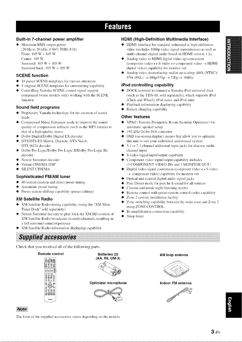
Check that you received all of the t_llowing parts.
Remote control Batteries (2)
_ (AA, R6, UM-3)
Optimizer microphone
0000
The form of the supplied accessories varies depending on tile models.
AM loop antenna
Indoor FM antenna
3 En
Page 8
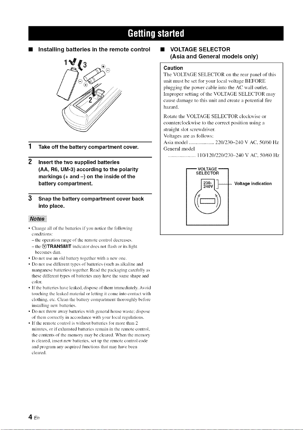
• Installing batteries in the remote control
1
Take off the battery compartment cover.
2
Insert the two supplied batteries
(AA, R6, UM-3) according to the polarity
markings (+ and -) on the inside of the
battery compartment.
Snap the battery compartment cover back
into place.
• VOLTAGE SELECTOR
(Asia and General models only)
Caution
The VOLTAGE SELECTOR on the rear panel of this
unit must be set for your local voltage BEFORE
plugging the power cable into the AC wall outlet.
hnproper setting of the VOLTAGE SELECTOR may
cause damage to this unit and create a potential fire
hazard.
Rotate the VOLTAGE SELECTOR clockwise or
counterclockwise to the correct position using a
straight slot screwdriver.
Voltages are as follows:
Asia model ................... 220/230-240 V AC, 50/60 Hz
General model
..................... 110/120/220/230-240 V AC, 50/60 Hz
VOLTAGE
SELECTOR
Voltage indication
• Change all of the batteries if you notice the following
conditions:
the operation range of the remote control decreases.
the @TRANSMIT indicator does not llash or its light
becomes dim.
• Do not use an old battery together with a new one.
• Do not use dilTcrent types of batteries (such as alkaline and
manganese batteries) together. Read the packaging carelully as
these dilTerent types of batteries may have the same shape and
color.
• lfthe batteries have leaked, dispose of them immediately. Avoid
touching the leaked material or letting it come into contact with
ch)thing, etc. Clean the battery compartment thoroughly befl)re
installing new batteries.
• Do not throw away batteries with general house waste: dispose
of them correctly in accordance with your local regulations.
• If the remote control is without batteries lot more than 2
minutes, or if exhausted batteries remain in the rmnote control.
the c()ntents of the memory may be cleared. When the memory
is cleared, insert new batteries, set up the rmnote control code
and program any acquired functions that may have been
cleared.
4 En
Page 9
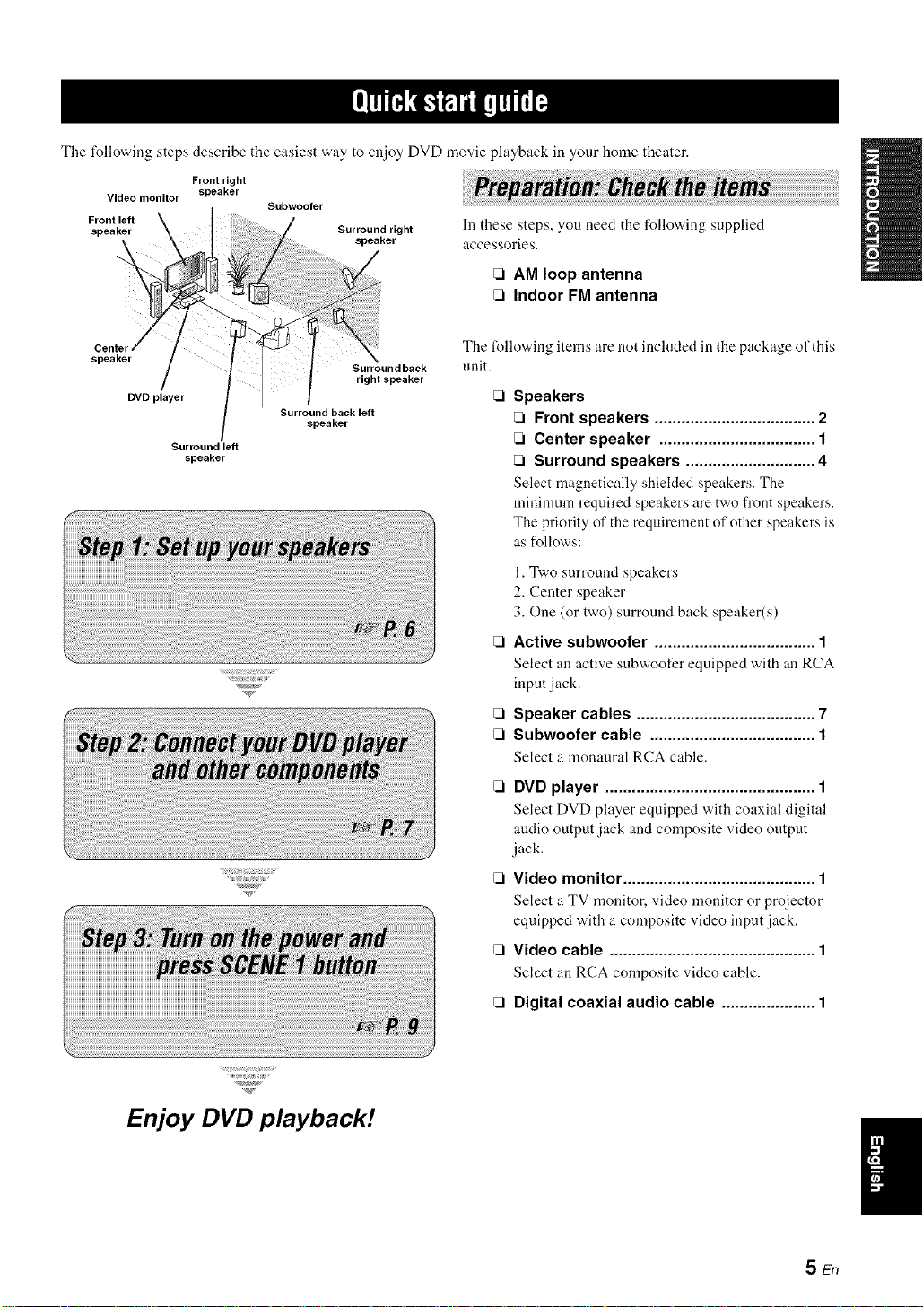
Tile following steps describe the easiest way to enjoy DVD movie playback in your home theater.
Front right
Video monitor
speaker
Subwoofer
In these steps, you need the following supplied
accessories.
[71AM loop antenna
[71Indoor FM antenna
The following items are not included in the package of this
unit.
Speakers
[71Front speakers .................................... 2
Surround left
speaker
[71Center speaker ................................... 1
[71Surround speakers ............................. 4
Select magnetically shielded speakers. The
minimum required speakers are two front speakers.
The priority of the requirement of other speakers is
as follows:
1. Two surround speakers
2. Center speaker
3. One (or two) surround back speaker(s)
[71Active subwoofer .................................... 1
Select an active subwoofer equipped with an RCA
input jack.
[71Speaker cables ........................................ 7
[71Subwoofer cable ..................................... 1
Select ;t monaural RCA cable.
Enjoy DVD playback!
[71DVD player ............................................... 1
Select DVD player equipped "adth coaxial digital
andio output jack and composite video output
jack.
Video monitor ........................................... 1
Select a TV monitor, video monitor or proiector
equipped with a composite video input jack.
CI Video cable .............................................. 1
Select an RCA composite video cable.
[71Digital coaxial audio cable ..................... 1
SEn
Page 10
Ifp_T_,_-;. a.lqi'; i-
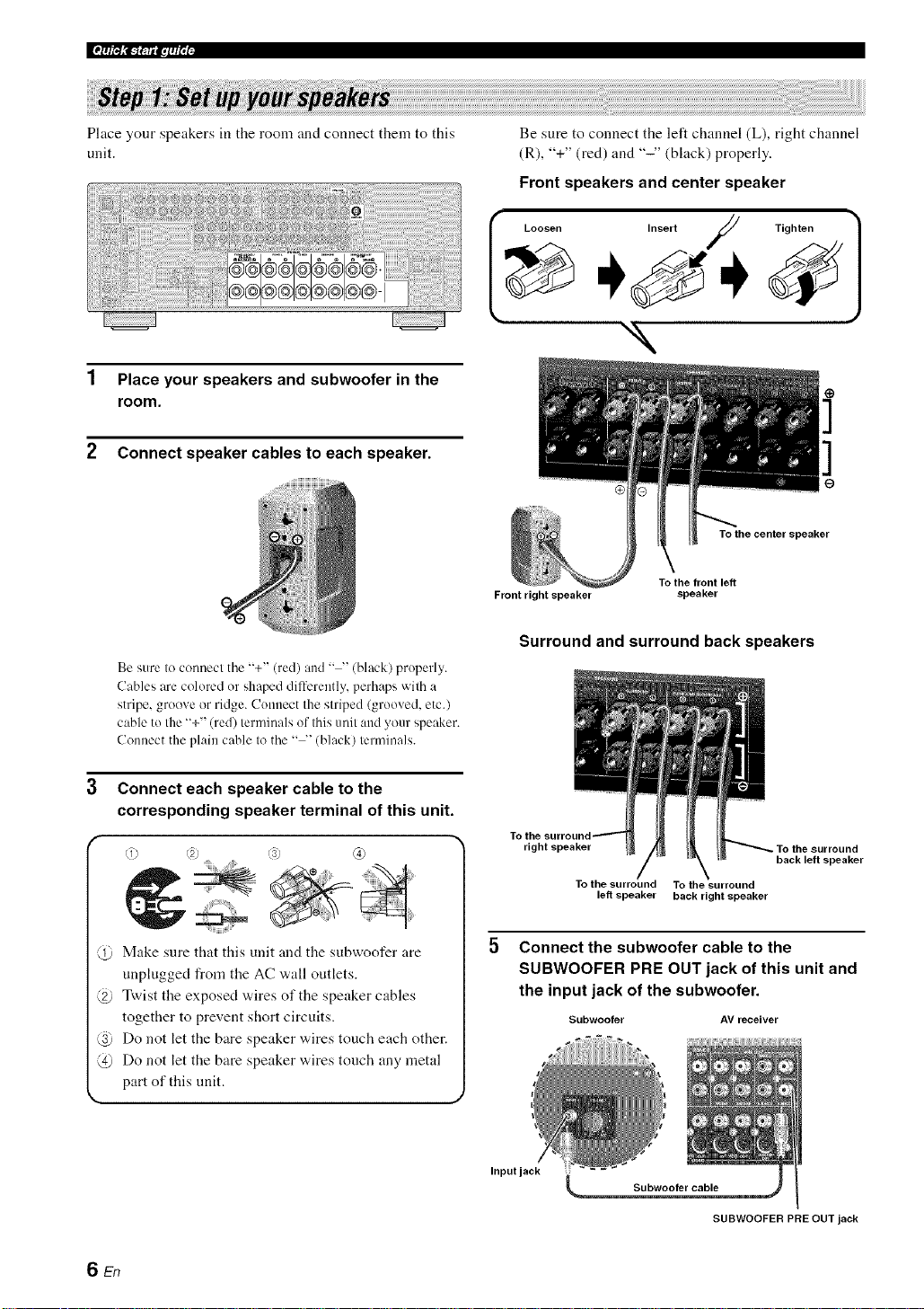
Place your speakers in the room and connect them to this
unit.
1 Place your speakers and subwoofer in the
room.
2 Connect speaker cables to each speaker.
Be sure to connect the "+" (red) and .... (black) properly.
Cables are colored or shaped differently, perhaps with a
stripe, groove or ridge. Connect the striped (grooved, etc.)
cable to the "+" (red) terminals of this unit and your speaker.
Connect the plain cable to the .... (black) terminals.
Be sure to connect the left channel (L), right channel
(R), "+" (red) and "-" (black) properly.
Front speakers and center speaker
I oosen Insert / Tighten 1
"N
To the center speaker
\
To the front left
Front right speaker
Surround and surround back speakers
speaker
3 Connect each speaker cable to the
corresponding speaker terminal of this unit.
f
@ Make sure that this unit and the subwoofer are
unplugged from the AC wall outlets.
@ Twist the exposed wires of the speaker cables
together to prevent short circuits.
@ Do not let the bare speaker wires touch each other.
@ Do not let the bare speaker wires tonch any metal
part of this nnit.
6En
right speaker
To the surround To the surround
left speaker back right speaker
Connect the subwoofer cable to the
SUBWOOFER PRE OUT jack of this unit and
the input jack of the subwoofer.
Subwoofer AV receiver
Inputjack _
Subwoofer cable
SUBWOOFER PRE OUT jack
back left speaker
Page 11

Connect the video cable to the composite
video output jack of your DVD player and
DVD VIDEO jack of this unit.
AV receiver
DVD player
Make sure that this unit and the DVD
player are unphigged from the AC
wall ontlets.
Connect the digital coaxial audio cable to the
digital coaxial audio output jack of your DVD
player and the DVD DIGITAL INPUT COAXIAL
jack of this unit.
DVD player AV receiver
Digital coaxial
audio output
jack
Digital coaxial audio
DVD DIGITAL INPUT
COAXIAL jack
DVD VIDEO jack
Composite video
output jack Video cable
3 Connect the video cable to the VIDEO
MONITOR OUT jack of this unit and the video
input jack of your video monitor.
Video monitor AV receiver
Video
input jack
Video cable
VIDEO MONITOR OUT jack
7 En
Page 12
Ifp_T_,_-r. a.l. fi';i-
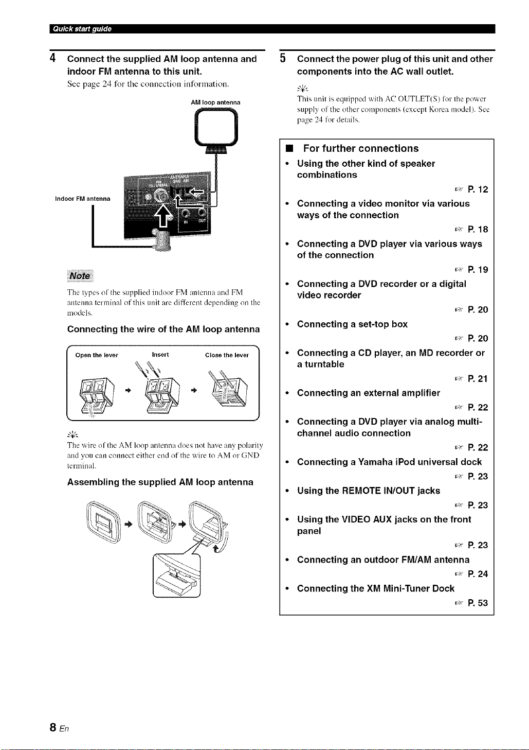
Connect the supplied AM loop antenna and
indoor FM antenna to this unit.
See page 24 for tile connection information.
AM loop antenna
©
Indoor FM antenna
I
The types of the supplied indoor FM antenna and FM
antemm terminal of this unit are different depending on the
models.
Connecting the wire of the AM loop antenna
Open the lever Close the lever
The wire of theAM loop antenna doesnot have anypolarity
andyou can connect either end of the wire to AM or GND
terminah
Assembling the supplied AM loop antenna
Insert
Connect the power plug of this unit and other
components into the AC wall outlet.
-'#-
Thisunit is equipped with AC OUTLET(S) lot thepower
supply of the other components (except Korea model).See
page 24 fordetails.
• For further connections
• Using the other kind of speaker
combinations
_,_ P. 12
• Connecting a video monitor via various
ways of the connection
_ P. 18
• Connecting a DVD player via various ways
of the connection
_ P. 19
• Connecting a DVD recorder or a digital
video recorder
_ P. 20
• Connecting a set-top box
_ P. 20
• Connecting a CD player, an MD recorder or
a turntable
_ P. 21
• Connecting an external amplifier
_,_ P. 22
• Connecting a DVD player via analog multi-
channel audio connection
_ P. 22
• Connecting a Yamaha iPod universal dock
_ P. 23
• Using the REMOTE IN/OUT jacks
_ R 23
• Using the VIDEO AUX jacks on the front
panel
_ P. 23
• Connecting an outdoor FM/AM antenna
_ P. 24
• Connecting the XM Mini-Tuner Dock
_ P. 53
SEn
Page 13
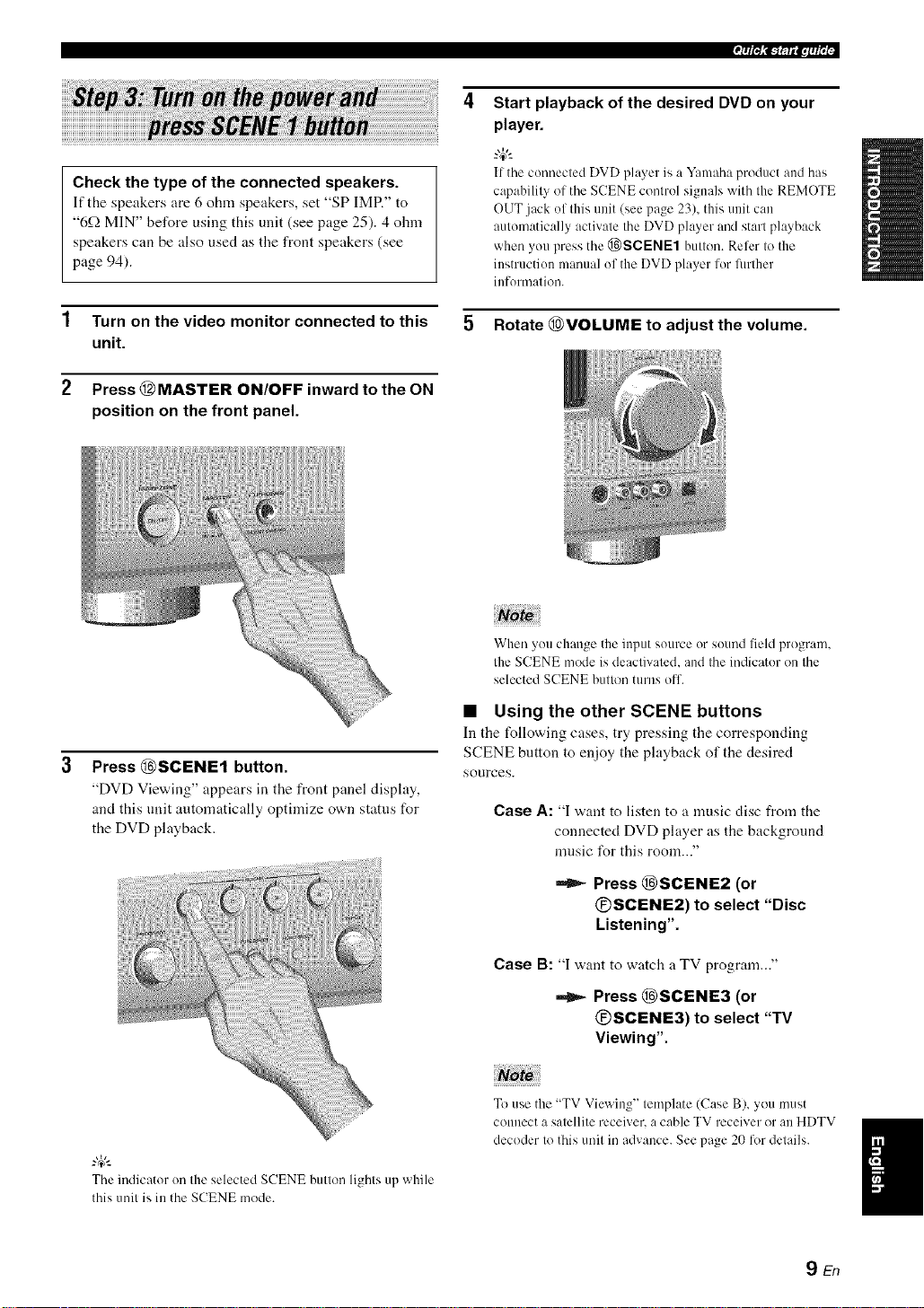
Start playback of the desired DVD on your
player.
Check the type of the connected speakers.
If the speakers are 6 ohm speakers, set "SP IMR" to
"6_QMIN" before using this unit (see page 25). 4 ohm
speakers can be also used as the front speakers (see
page 94).
1 Turn on the video monitor connected to this
unit.
2 Press @MASTER ON/OFF inward to the ON
position on the front panel.
tf the connected DVD pla_er is a Y:mmha product :rodhas
capahilit_ of the SCENE control signals with the REMOTE
OUT jack of this unit (see page 23), this unit can
automatically activate the DVD player and start playback
when you press the @)SCENE1 button. Refer to the
instruction manual of the DVD player lor fimher
inlonnation.
5 Rotate @VOLUME to adjust the volume.
When you change the input source or sound field progran].
the SCENE mode is deactivated, and the indicator on the
selected SCENE button turns ofl.
3
Press @SCENE1 button.
"DVD Viewing" appears in the front panel display,
and this unit automatically optimize own status for
the DVD playback.
The indicator on the selected SCENE button lights up while
this unit is in the SCENE mode.
• Using the other SCENE buttons
In tile following cases, try pressing tile corresponding
SCENE button to enjoy the playback of the desired
sources.
Case A: "I want to listen to a music disc from the
connected DVD player as the background
music I\_rthis room..."
Press @SCENE2 (or
@SCENE2) to select "Disc
Listening".
Case B: "I want to watch a TV program..."
Press @SCENE3 (or
@SCENE3) to select "TV
Viewing".
To use the "TV Viewing" template (Case B), you must
connect a satellite receiver, a cable TV receiver or an HDTV
decoder to this unit in advance. See page 20 lot details.
9En
Page 14
Ifp_T_,_-r. a.lqi'; i-
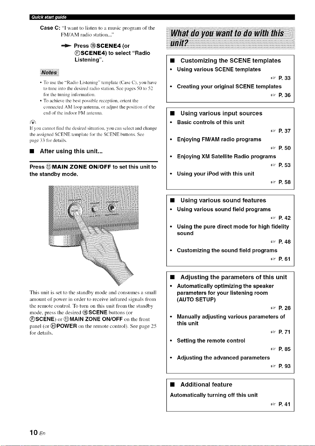
Case C: "1 want to listen to a mnsic program of the
FM/AM radio station..."
Press @SCENE4 (or
®SCENE4) to select "Radio
Listening".
• To use the"Radio Listening" template (Case C), you have
to tune intothe desired radio station. See pages 50 to 52
for the tuninginformation.
• To achieve the best possible reception, orient the
connected AM loop antenna, or a@lst theposition of the
endof the indoorFM antemm.
--'4¢--
If you catmot findthe desired situation,you can select andchange
the assignedSCENE template lor theSCENE buttons. See
page 33 fordetails.
• After using this unit...
Press @MAIN ZONE ON/OFF to set this unit to
the standby mode.
• Customizing the SCENE templates
• Using various SCENE templates
r,_ p. 33
• Creating your original SCENE templates
_._ P. 36
• Using various input sources
• Basiccontrols of this unit
r_ p. 37
• Enjoying FM/AM radio programs
_._ P. 50
• Enjoying XM Satellite Radio programs
_ P. 53
• Using your iPod with this unit
_ P. 58
• Using various sound features
• Using various sound field programs
_ P. 42
• Using the pure direct mode for high fidelity
sound
_ P. 48
• Customizing the sound field programs
r_ p. 61
This unit is set to the standby mode and consumes a small
amount of power in order to receive infrared signals from
the remote control. To turn on this unit from the standby
mode, press the desired @SCENE buttons (or
@SCENE) or @MAIN ZONE ON/OFF on the front
panel (or @POWER on the remote control). See page 25
for details.
10 En
• Adjusting the parameters of this unit
• Automatically optimizing the speaker
parameters for your listening room
(AUTO SETUP)
_-_ P. 28
• Manually adjusting various parameters of
this unit
_ P. 71
• Setting the remote control
_ P. 85
• Adjusting the advanced parameters
r._ p. 93
• Additional feature
Automatically turning off this unit
_.>P. 41
Page 15
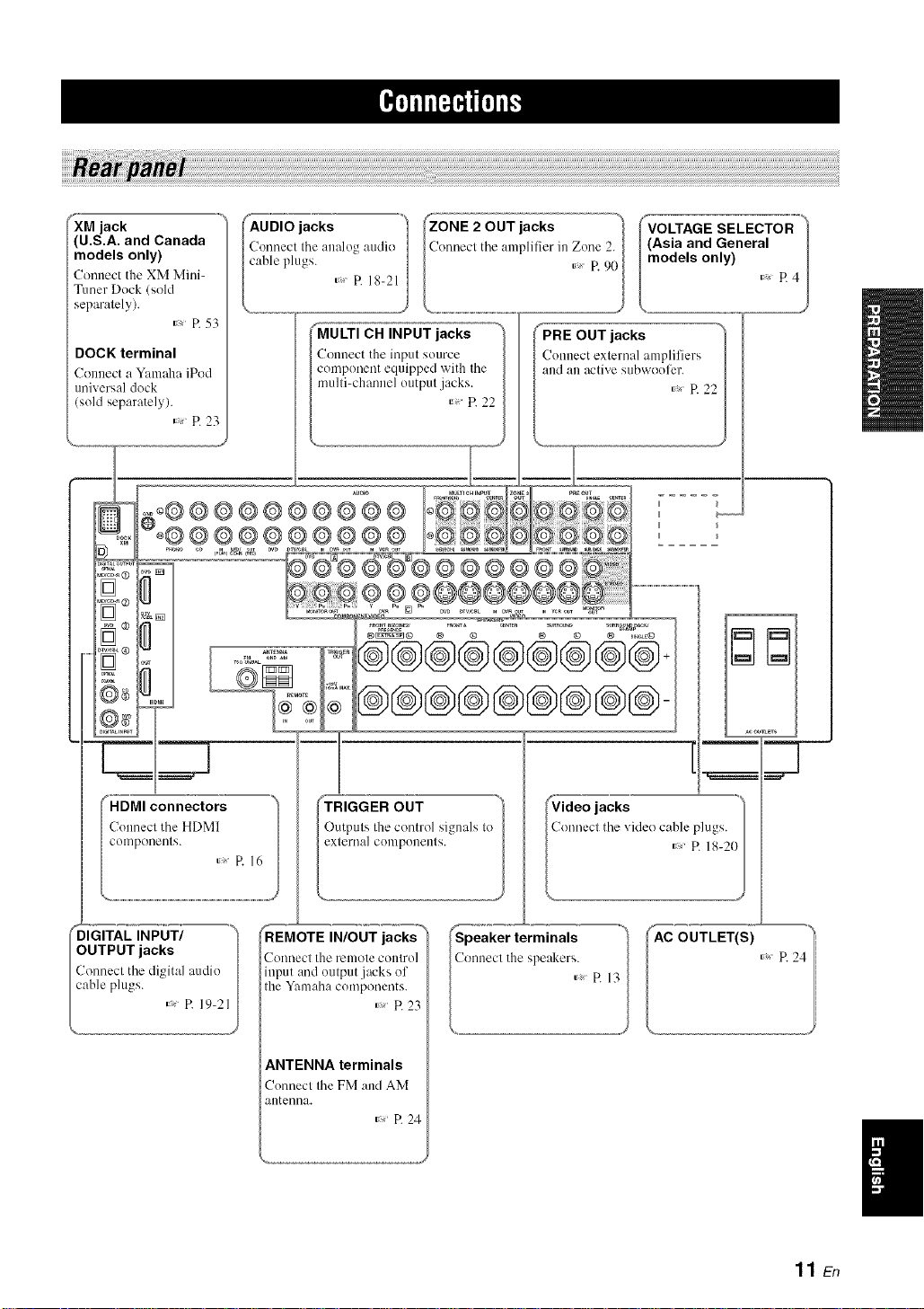
_XM jack .....
(U.S.A. and Canada
models only)
Connect the XM Mini-
Tuner Dock (sold
separalely).
R 53
DOCK terminal
Connect a Y:mmha iPod
universal dock
(sold separately).
P. 23
ii_@@@@@@@@@@
o®®®®®®®®®® ,°
oo[
j ......:=, ®8®®®®®
)B
CH INPUT jacks
t the input source
lent equipped with the
lannel otltptll jacks.
_umo
I
I
®
('i'iD M_ connectors
/Connectthe HDMI
colnpone//ls.
_'_._£ INPUT/ ")
OUTPUT jacks I
Connecl the digital audio I
cable plugs.
_l_ OUT
Outputs the control signals to
external conlponenls.
P. 16
REMOTE IN/OUT jacks
'onnecl tile renlole COlllrO]
input and output jacks ol
tile Yanlaha components.
ANTENNA terminals
Connect the FM and AM
antenna.
R 23
_, P. 24
IAC OUTLET(S) R 24"/
11 En
Page 16
[[¶'tlfl[_'_ffql_
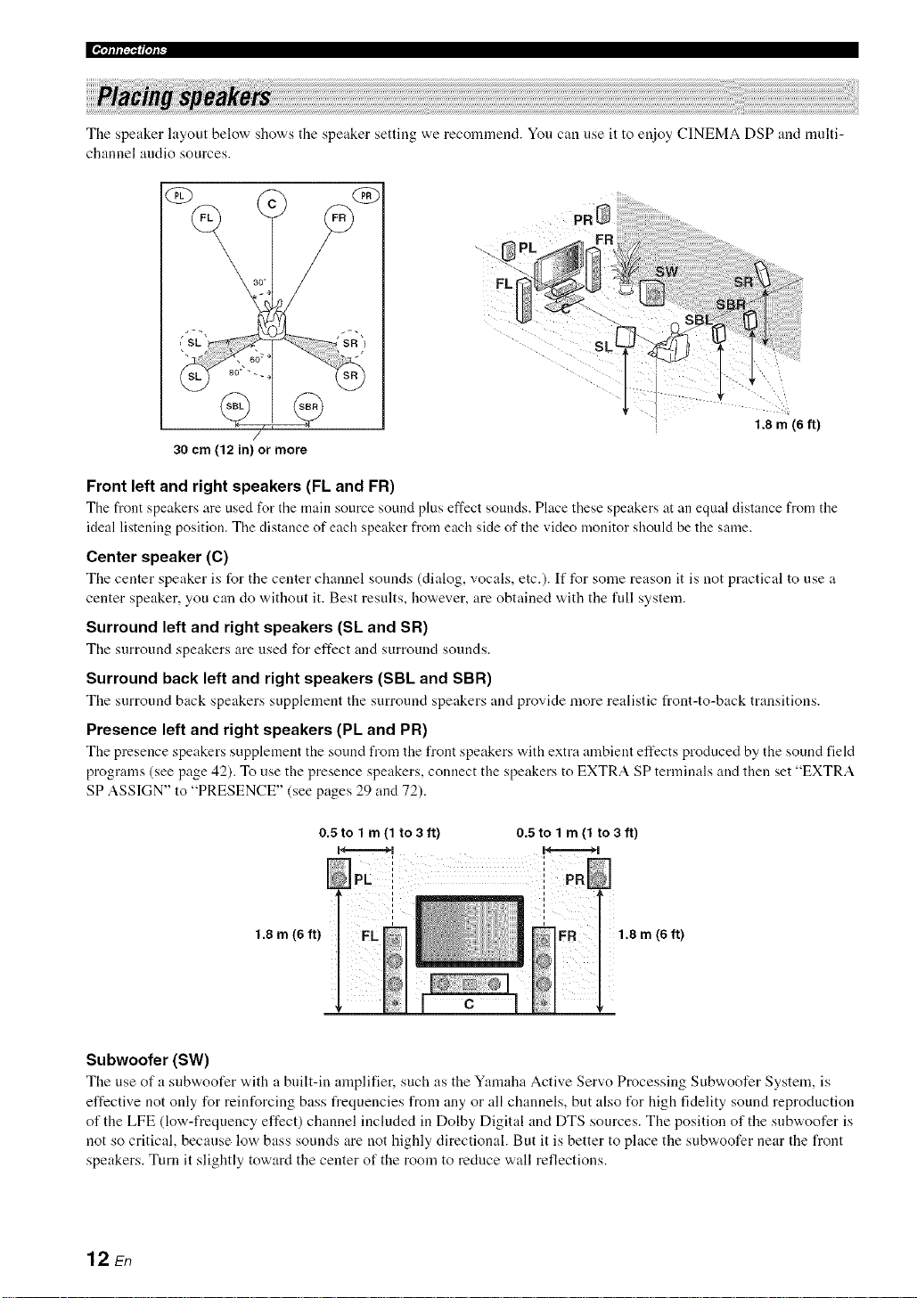
The speaker layout below sllows the speaker setting we recommend. You can use it to enjoy CINEMA DSP and multi-
channel audio sources.
\
30 cm (12 in) or more
Front left and right speakers (FL and FR)
The front speakers are used for tile main source sotmd plus effect sounds. Place these speakers z_tan equal distance from the
ideal listening position. The distance of each speaker from each side of the video monitor should be the same.
Center speaker (C)
The center speaker is for the center channel sounds (dialog, vocals, etc.). If for some reason it is not practical to use a
center speaker, you can do without it. Best results, however, are obtained with the full system.
Surround left and right speakers (Sk and SR)
The surround speakers are used for effect and surround sounds.
Surround back left and right speakers (SBL and SBR)
The surround back speakers supplement the surround speakers and provide more realistic front-to-back transitions.
Presence left and right speakers (PL and PR)
The presence speakers supplement the sound from the front speakers with extra ambient effects produced by the sound field
programs (see page 42). To use the presence speakers, connect the speakers to EXTRA SP terminals and then set "EXTRA
SP ASSIGN" to "PRESENCE" (see pages 29 and 72).
/
0.5 tolm(lto3ft)
H............=...._ H..........=......_
0.5 to 1 m (1 to 3 ft)
, 1.8 m (6 ft)
i
1.8 m (6 ft)
1.8 m (6 ft)
Subwoofer (SW)
The use of a snbvvoofer with a built-in amplifier, such as the Yamaha Active Servo Processing Subwoofer System, is
effective not only for reinforcing bass frequencies from any or all channels, but also for high fidelity sound reproduction
of the LFE (low-frequency effect) channel included in Dolby Digital and DTS sources. The position of the subwoofer is
not so critical, because low bass sounds are not highly directional. But it is better to place the subwoofer near the front
speakers. Turn it slightly toward the center of the room to reduce wall reflections.
12 En
Page 17
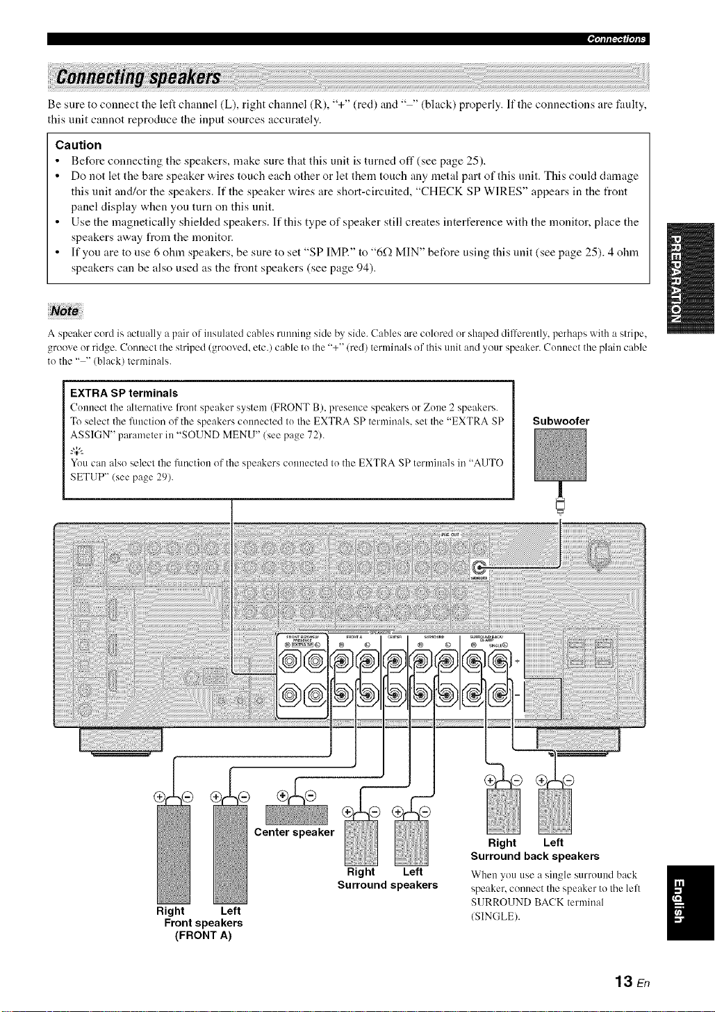
Be sure to connect the left channel (L), right channel (R), "+" (red) and .... (black) properly. If the connections are faulty,
this unit cannot reproduce the input sources accurately.
Caution
• Before connecting the speakers, make sure that this unit is turned off (see page 25).
• Do not let the bare speaker wires touch each other or let them touch any metal part of this unit. This coukt damage
this unit and/or the speakers. If the speaker wires are short-circuited, "CHECK SP WIRES" appears in the front
panel display when you turn on this unit.
• Use the magnetically shielded speakers. If this type of speaker still creates interference with the monitor, place the
speakers away from the monitor.
• If you are to use 6 ohm speakers, be sure to set "SP IMR" to "6f.) MIN" before using this unit (see page 25). 4 ohm
speakers can be also used as the front speakers (see page 94).
A speaker c®rd is actually a pail" of insulated cables running side by side. Cables are col®red ®rshaped differenlly, perhaps with a stripe,
gr®®veor ridge. C®nnecl the striped (gro®ved, etc.) cable Il! the "+" (red) terminals ®f Ihis unit and your speaker. Connect the plain cable
t®the .... (black) terminals.
EXTRA SP terminals
Connect the alternative li'ont speaker system (FRONT B), presence speakers or Zone 2 speakers.
To select the Rmction of the speakers connected to the EXTRA SP terminals, set the "EXTRA SP
ASSIGN" parameter ill "SOUND MENU" (see page 72).
-"4;'-
You call also select the function of the speakers connected to the EXTRA SP terminals in "AUTO
SETUP" (see page 29).
Subwoofer
Right Left
Front speakers
(FRONT A)
Center ea er
Right Left
Surround speakers
Right Left
Surround back speakers
When you use a single surround back
speaker,c®nnectthe speaker to the lell
SURROUND BACKterminal
(SINGLE).
13 En
Page 18
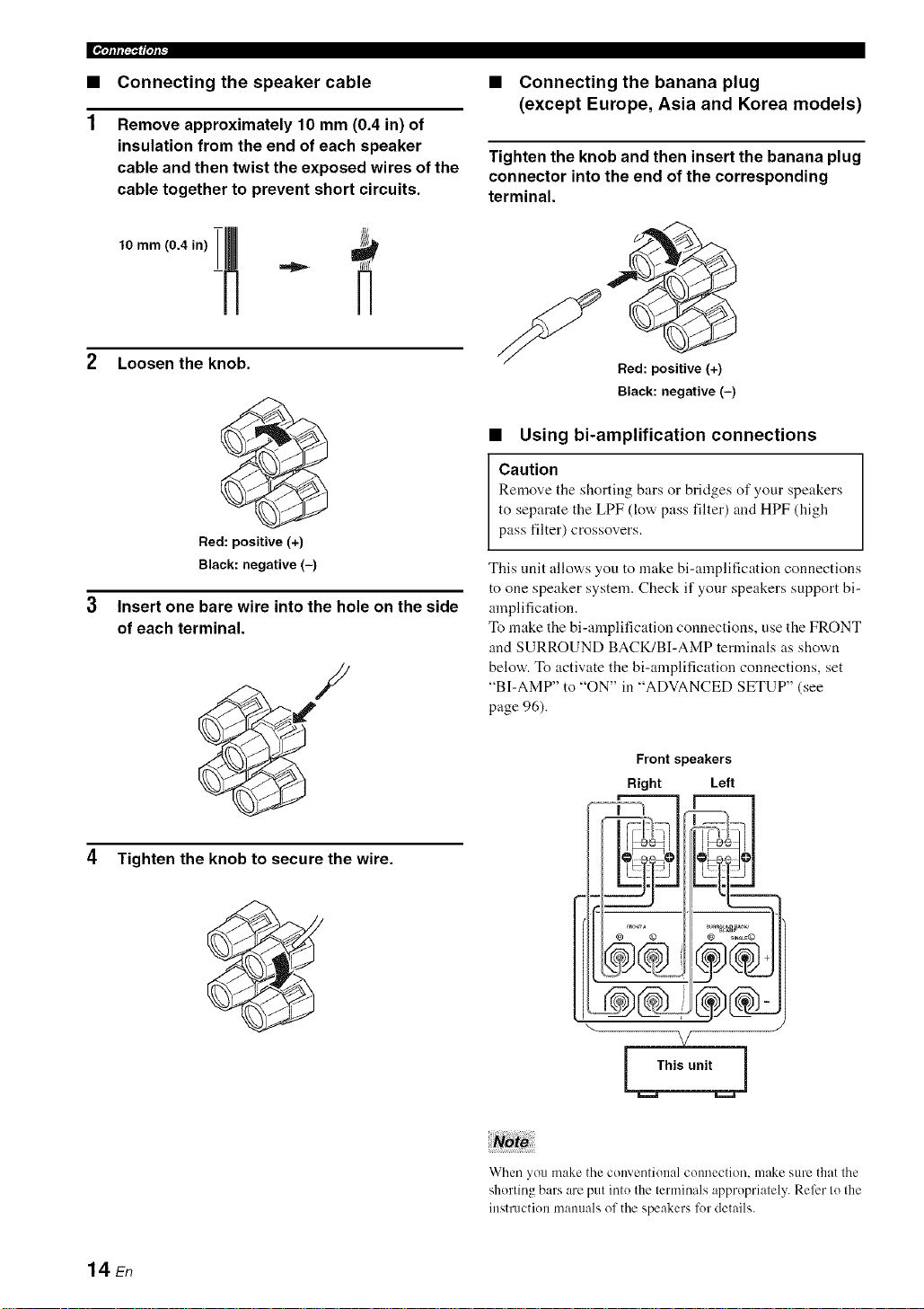
• Connecting the speaker cable
Remove approximately 10 mm (0.4 in) of
insulation from the end of each speaker
cable and then twist the exposed wires of the
cable together to prevent short circuits.
• Connecting the banana plug
(except Europe, Asia and Korea models)
Tighten the knob and then insert the banana plug
connector into the end of the corresponding
terminal.
2 Loosen the knob.
Bed: positive (+)
Black: negative (-)
Insert one bare wire into the hole on the side
of each terminal.
4 Tighten the knob to secure the wire.
Bed: positive (+)
Black: negative (-)
• Using bi-amplification connections
Caution
Remove the shorting bars or bridges of your speakers
to separate the LPF (low pass filter) and HPF (high
pass filter) crossovers.
This unit allows you to make bi-amplification connections
to one speaker system. Check if your speakers support bi-
amplification.
To make the bi-amplification connections, use the FRONT
and SURROUND BACK/BI-AMP terminals as shown
below. To activate the bi-amplification connections, set
"BI-AMP" to "ON" in "ADVANCED SETUP" (see
page 96).
Front speakers
Right Left
14 En
When you make the conventional connection, make sure tllat the
shorting bars are put into the terminals appropriately. Refer Io tile
instruction manuals ol the speakers for details.
Page 19
.qlflI_gqP
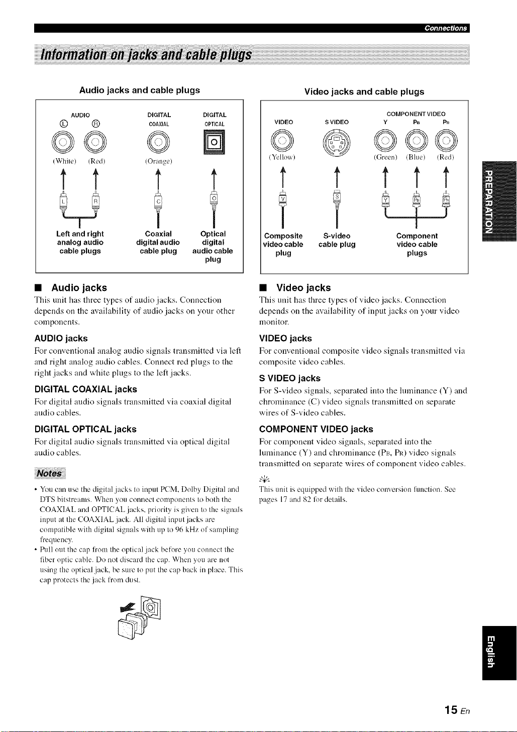
Audio jacks and cable plugs
AUDIO DIGITAL
© ® COAX,AL
DIGITAL
OPTICAL
©© ©
(White) (Red) (Orange)
t t t
Left and right Coaxial
analog audio digital audio
cable plugs cable plug
• Audio jacks
This unit has three types of audio jacks. Connection
depends on the availability of audio jacks on your other
components.
AUDIO jacks
For conventional analog audio signals transmitted via left
and right analog audio cables. Connect red plugs to the
right jacks and white plugs to the left jacks.
DIGITAL COAXIAL jacks
For digital audio signals transmitted via coaxial digital
audio cables.
t
Optical
digital
audio cable
plug
Video jacks and cable plugs
COMPONENTVIDEO
VIDEO S VIDEO Y F_ Pn
© @©oo
(Yellow) (Green) (Blue) (Red)
t t t t t
Y f
Composite S-video Component
video cable cable plug video cable
plug plugs
• Video jacks
This unit hits three types of video jacks. Connection
depends on the availability of input jacks on your video
monitor.
VIDEO jacks
For conventional composite video signals transmitted via
composite video cables.
S VIDEO jacks
For S-video signals, separated into the lumin:mce (Y) and
chrominance (C) video signals transmitted on separate
wires of S-video cables.
DIGITAL OPTICAL jacks
For digital audio signals transmitted via optical digital
:radio cables.
• You can use the digital jacks to input PCM. Dolby Digital and
DTS bitstreams. When you connect components to both the
COAXIAL and OPTICAL jacks, priority is given to the signals
input at the COAXIAL jack. All digital input jacks are
compatible with digital signals with up to 96 kHz of sampling
lbequency.
• Pull out the cap fi'om the optical jack before you connect the
fiber optic cable. Do not discard the cap. When you are not
using the optical .jack. be sure to put the cap back in place. This
cap protects the.jack lrom dust.
COMPONENT VIDEO jacks
For component video signals, separated into the
luminance (Y) and chrominance (Pro PIO video signals
transmitted on separate wires of component video cables.
"4C--
Thisunit is equipped with the video conversion fimction. See
pages 17 and 82 lot details.
1hEn
Page 20
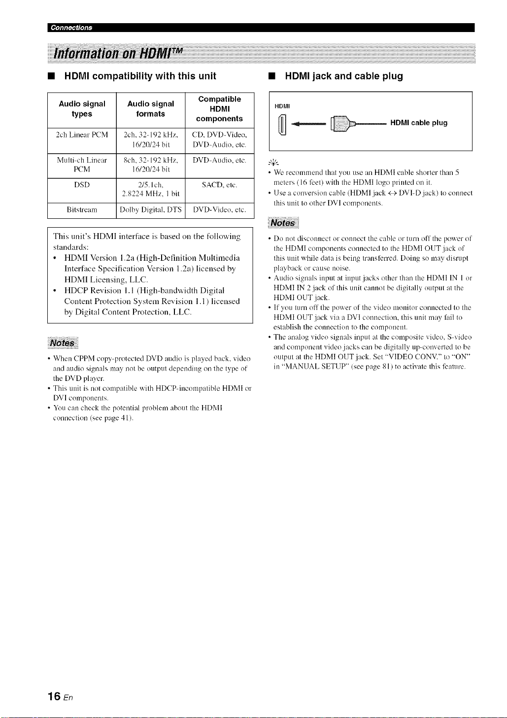
HDMI compatibility with this unit
• HDMI jack and cable plug
Audio signal
types
2ch Linear PCM
Multi-ch Linear
PCM
DSD
Bitstream
Audio signal Compatible
formats
2ch. 32-192 kHz. CD. DVD-Video.
16/20/24 bit DVD_Audio. etc.
8ch. 32_192 kHz. DVD_Audio. etc.
16/20/24 bit
2/5. Ich. SAC[). etc.
2.8224 MHz. I bit
Dolby Digital. DTS DVD-Video. etc.
HDMI
components
This unit's HDMI interface is based on the following
standards:
• HDMI Version 1.2a (High-Definition Multimedia
Interface Specification Version 1.2a) licensed by
HDMI Licensing, LLC.
• HDCP Revision 1.1 (High-bandwidth Digital
Content Protection System Revision 1.1) licensed
by Digital Content Protection, LLC.
• When CPPM copy-protected DVD audio is played back. video
and audio signals may not be output depending on the type of
the DVD player.
• This unit is not compatible with HDCP-incompatible HDMI or
DV] components.
• You can check the potential problem about the HDMI
connection (see page 41 ).
HDMI
HDMI cable plug
• We recommend that you use an HDMI cable shorter than 5
meters ( 16 feet) with the HDMI logo printed on it.
• Use a conversion cable (HDMI jack <_- DVI-D jack) to connect
this unit to other DVI components.
• Do not disconnect or connect the cable or turn off the power of
the HDMI components connected to the HDMI OUT jack of
this unit while data is being transli_rred. Doing so may disrupt
playback or cause noise.
• Audio signals input at input jacks other than the HDMI IN 1 or
HDMI IN 2 jack of this unit cannot be digitally output at the
HDMI OUT jack.
• If you turn ofl the power of the video monitor connected to the
HDMI OUT jack via a DVI connection, this unit may li/il to
establish the connection to the component.
• The analog video signals input at the composite video. S-video
arid component video jacks can be digitally up-converted to be
output at the HDMI OUT jack. Set "VIDEO CONV." to "ON"
in "MANUAL SETUP" (see page 81) to activate this feature.
16 En
Page 21
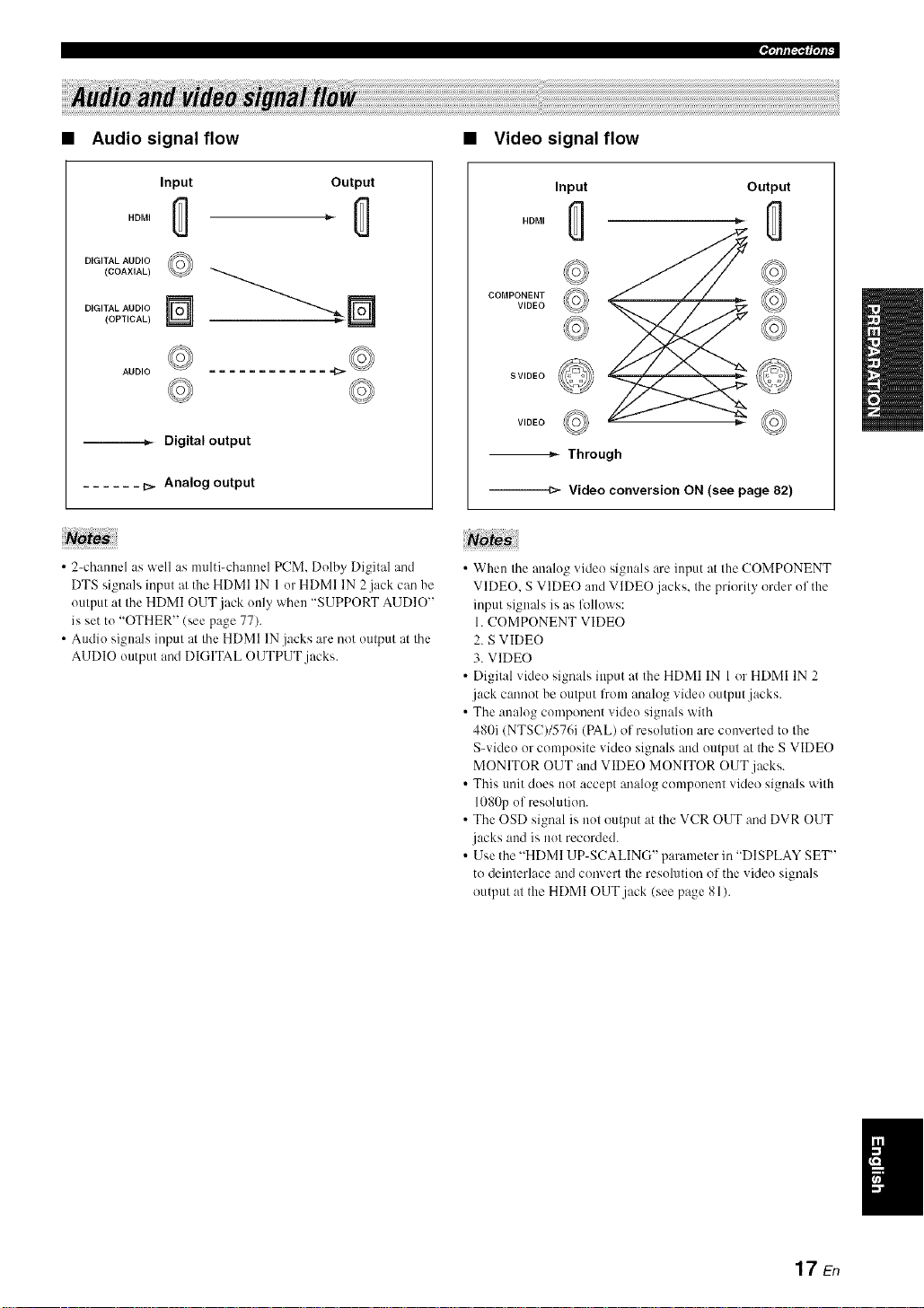
Audio signal flow
• Video signal flow
Input
HDMI
DIGITAL AUDIO
(COAXIAL)
DIGITAL AUDIO
(OPTICAL)
--._ Digital output
...... b_ Analog output
• 2-cham_el as well as multi-chamlcl PCM. Dolby Digital and
DTS signals input at the HDMI IN 1 or HDMI IN 2jack CaD be
output at the HDMI OUT.jack only when "SUPPORT AUDIO"
is Net to "OTHER" (Nee page 77).
• Audio signals input at the HDMI IN jacks arc not output at the
AUDIO output and DIGITAL OUTPUT jacks.
©
AUDIO
Output
Input
HDMI
COMPONENT
VIDEO
SVIDEO
VIDEO _ <_
Output
-_ Through
---m- Video conversion ON (see page 82)
• When the analog video signals are input at the COMPONENT
VIDEO, S VIDEO and VIDE() jacks, the priority order of the
input signals iNaN fl)IIGws:
1. COMPONENT VIDEO
2. S VIDE()
3. VIDEO
• Digital video signals input at the HDMI IN 1or HDMI IN 2
.jack CmmGtbe output lrom analog video output.jacks.
• The analog component video signals with
480i (NTSC)/576i (PAL) of resolution are converted to the
S-video or composite video signals and output at the S VIDE()
MONITOR OUT and VIDEO MONITOR OUT jacks.
• This trait clods not accept analog component video signals with
1080p of resolutiGn.
• The OSD signal iNnot output at the VCR OUT and DVR OUT
jacks and iNnot recorded.
• Use the "HDMI UP-SCALING" parameter in "DISPLAY SET"
to deinterlace add convert the resolution of the video signals
output at the HDMI OUT.jack (see page 81).
17En
Page 22
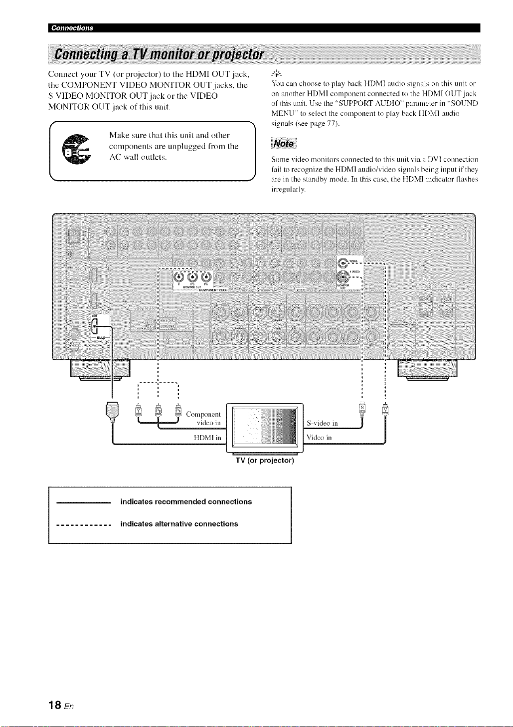
Connect your TV (or proiector) to the HDMI OUT jack,
the COMPONENT VIDEO MONITOR OUT jacks, the
S VIDEO MONITOR OUT jack or the VIDEO
MONITOR OUT jack of this unit.
Make sure that this unit and other
components are unplngged from the
AC wall outlets.
You can choose to play back HDMI audio signals on this unit or
on another HDMI component connected to the HDMI OUT jack
of this unit. Use the "SUPPORT AUDIO" parameter in "SOUND
MENU" to select the component to play back HDMI audio
signals (see page 77).
Some video monitors connecled to this unit via a DVI conneclion
fail to recognize the HDMI audio/video signals being input if they'
are in the slandby mode. In Ihis case. the HDMI indicalor flashes
irregularly.
18 En
video in
Componenl
HDMI in
indicates recommended connections
indicates alternative connections
TV (or projector)
IS-video in
]Vide() in
i
Page 23
components are unplugged from the
AC wall outlets.
I _1_ Make sure that this unit and other [
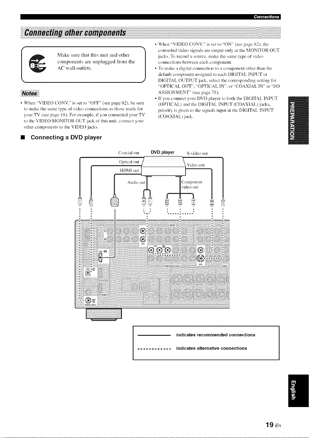
• When "VIDEO CONV." is set to "OFF" (see page 82), be sure
to make the same type of video connections as those made lk_r
your TV (see page 18). For example, if you connected your TV
to the VIDE() MONITOR OUT .jack of this unit. connect your
other components to the VIDE() jacks.
• Connecting a DVD player
Coaxial out DVD player S-video out
Optical out / :_Video out
HDkII ou,_ 1
• When "VIDEO CONV." is set to "ON" (see page 82), the
converted video signals are output only at the MONITOR OUT
jacks. To record a source, make the same type of video
com]ections between each component.
• To make a digital commction to a componeut other than the
delhult component assigned to each DIGITAL INPUT or
J
DIGITAL OUTPUT jack, select the corresponding setting for
"OPTICAL OUT". "OPTICAL IN". or "COAXIAL IN" in "110
ASSIGNMENT" (see page 78).
• If you cmmect your DVD player to both the DIGITAL INPUT
(OPTICAL) and the DIGITAL INPUT (COAXIAL)jacks.
priority is given to the signals input at the DIGITAL INPUT
(COAXIAL) jack.
.qfff[_{|°tP
)tll
indicates recommended connections
............ indicates alternative connections
19 En
Page 24
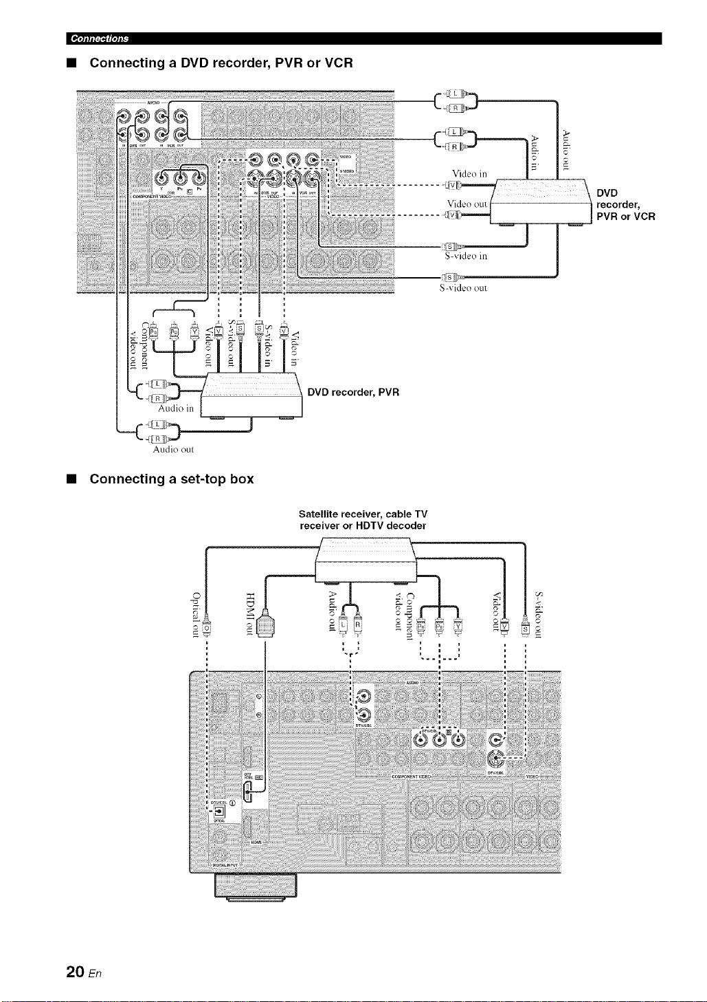
• Connecting a DVD recorder, PVR or VCR
DVD recorder, PVR
Audio oul
Connecting a set-top box
Satellite receiver, cable TV
receiver or HDTV decoder
©
20 En
Page 25
.qlflf_1_|qff
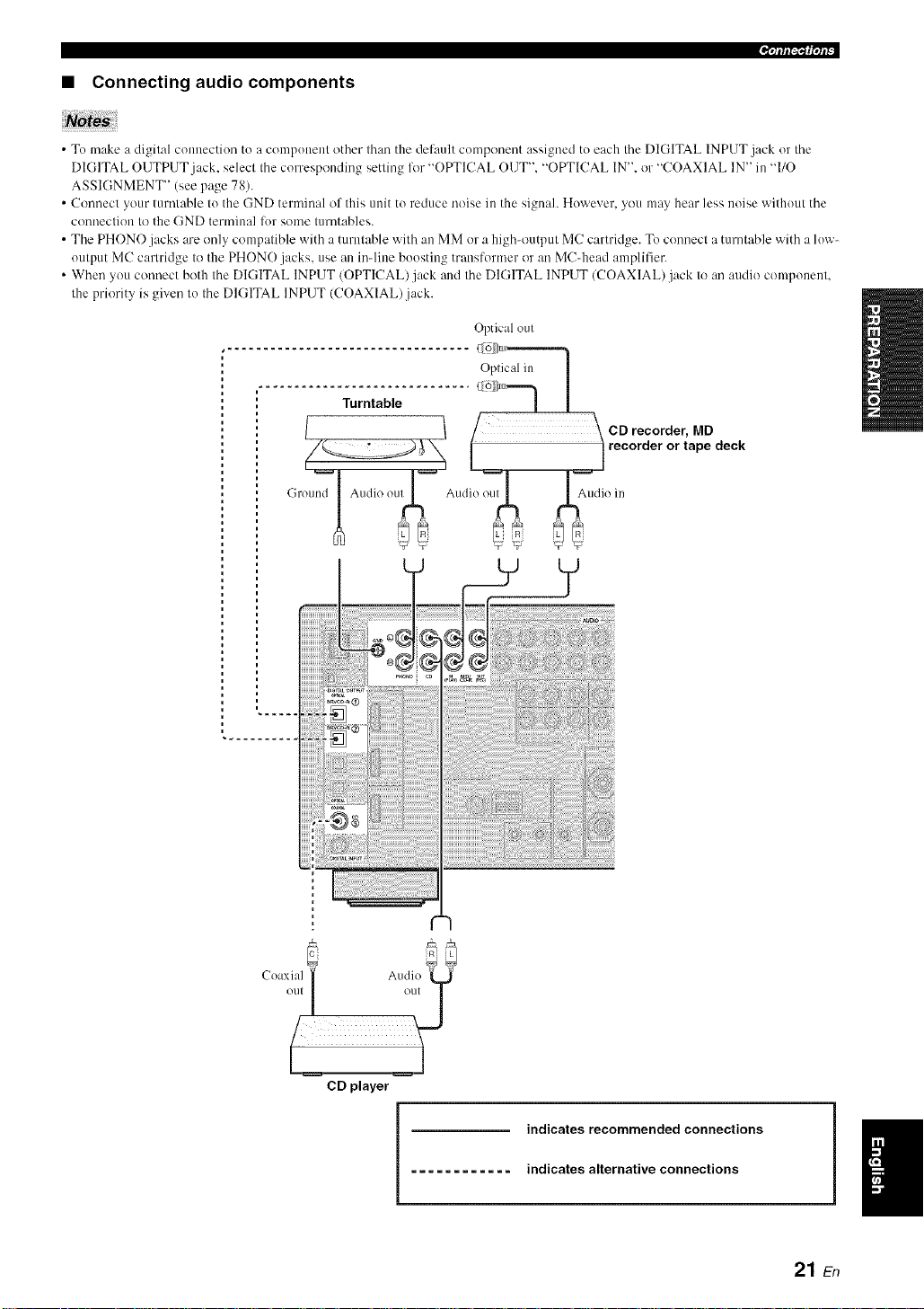
• Connecting audio components
• To make a digital comeection to a component other than the def:mlt component assigned to each the DIGITAL INPUT jack or the
DIGITAL OUTPUT jack. select the corresponding setting lot "OPTICAL OUT". "OPTICAL IN". or "COAXIAL IN" in "I/O
ASSIGNMENT" (see page 78).
• Commct your turntable to the GND terminal of this unit to reduce noise in the signah However, you may hear less noise without the
c(mnection to the GND terminal lor some turntables.
• The PHONO jacks are only compatible with a turntable with ale MM or a high<mtput MC cartridge. To connect a turntable with a low-
output MC cartridge to the PHONO jacks, use aleinqine boosting transformer or an MC_head amplifier.
• When you connect both the DIGITAL INPUT (OPTICAL)jack and the DIGITAL INPUT (COAXIAL)jack to an audio component.
the priority is given to the DIGITAL INPUT (COAXIAL).jack.
Optical out
Oplic:d in I
............ e.......... [
/ \ CD recorder, MD
_ _ 1 rec°rder °r tape deck
• )u7 Audio ou " Ii( in
,,oundI 2'd"
AA A;', AA
uu _÷"U _ _ 9 U
5JE, LL R 5J Lit,
C(axial _ Audio
) ( _vfl ,
2
CD player
indicates recommended connections
indicates alternative connections
21 En
Page 26

• Connecting an external amplifier
This unit has more than enough po'a, er for any home use. However. if you want to add more power to the speaker ontput
or if you want to use another amplifier, connect an external amplifier to the PRE OUT jacks. Each PRE OUT jack outputs
the same channel signals as the corresponding SPEAKERS terminals.
Notes
• When you make connections to the PRE OUT jacks, do not make connections to the SPEAKERS terminals.
• The signals output at the FRONT PRE OUT jacks are al'li:cted by the TONE CONTROL settings (see page 48).
• A;ljust the vohnne level of the subwooli:r with the control on the subwoofcr (see page 48).
• Some signals may not be output at the SUBWOOFER PRE OUT jack depending on the settings for "SPEAKER SET" (see page 72)
and "LFE/BASS OUT" (see page 72).
@ SUR.BACK PRE OUT jacks
Surround back channel output jacks. When you only
connect one external amplifier for the surround back
channel, connect it to the SINGLE jack.
• When "BbAMP" is set to "ON'. this unit outputs the front
channel audio signals at the SUR.BACK PRE OUT.jacks.
@ FRONT PRE OUT jacks
Front channel output jacks.
@ SURROUND PRE OUT jacks
Surround channel output jacks.
• The audio signals output at the SUR.BACK PRE OUT jacks
differ depending on the "EXTRA SP ASSIGN" setting (see
page 72).
@ SUBWOOFER PRE OUT jack
Connect a subwoofer with a built-in amplifier.
@ CENTER PRE OUT jack
Center channel output jack.
• Connecting a multi-format player or an external decoder
This unit ts equipped w,ith 6 additional input jacks (left and right FRONT, CENTER, left and right SURROUND and
SUBWOOFER) for discrete multi-channel input from a nmlti-format player, external decoder, sound processor or pre-
anaplifier.
If you set "INPUT CH" to "8CH" in "MULTI CH SET" (see page 80), you can use the input jacks assigned as "FRONT"
in "MULTI CH SET" (see page 80) together with the MULTI CH INPUT jacks to input 8-channel signals.
Connect the output jacks on your multi-format player or external decoder to the MULTI CH INPUT jacks. Be sure to
match the left and right outputs to the left and right input jacks for the front and surround channels.
notes
• When you select the component connected to the MULTI CH INPUT jacks as the input source (see page 38), this unit automatically
turns off the digital sound field processor, and you cannot select sound field programs.
• This unit does not redirect signals input at the MULTI CH INPUT jacks to accommodate lbr missing speakers. We recommend that
you connect at least a 5. I-channel speaker system belbre using this feature.
- r_ULTECH EHPUT
Multi-format player/External
decoder (5.1-channel output)
'I The analog audio input jacks assigned as "FRONT" in
"MULTI CH SET" (see page 80).
Multi-format player/External
decoder (7.1-channel output)
22 sn
Page 27
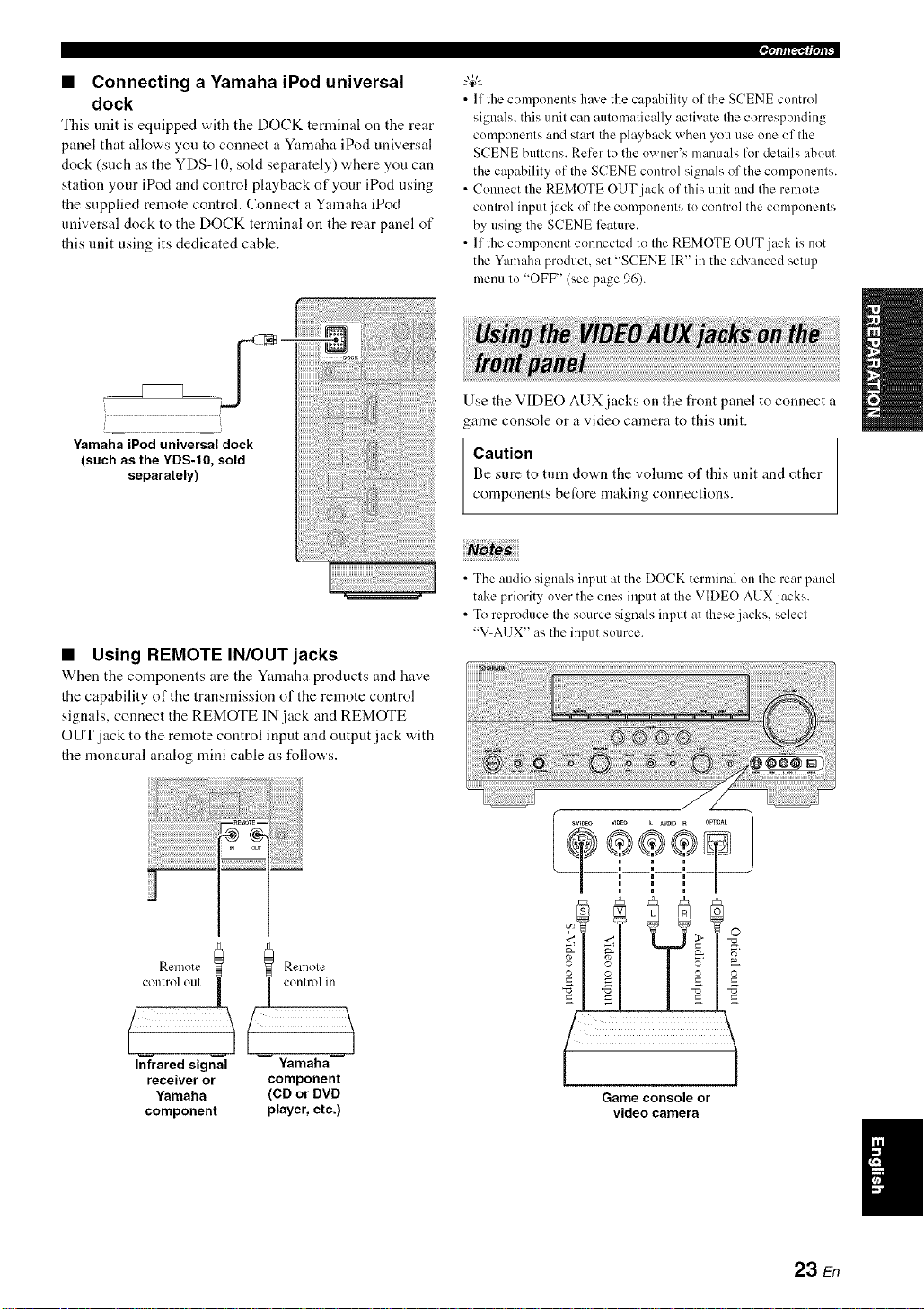
• Connecting a Yamaha iPod universal
dock
This unit is equipped with tile DOCK ternlinal on the rear
panel that allows you to connect a Yamaha iPod universal
dock (such as the YDS-10, sold separately) where you can
station your iPod and control playback of your iPod using
the supplied remote control. Connect a Yamaha iPod
universal dock to the DOCK terminal on the rear panel of
this unit using its dedicated cable.
.qlffl'_1_|'/l_"
• If the components haxe the capahility of the SCENE control
signals, this unit can automatically activate the corresponding
components and start the playback when you use one of the
SCENE buttons. Refer to the owner's manuals for details about
the capability of the SCENE control signals of the components.
• Connect the REMOTE OUT jack of this unit and the remote
control input jack of the components to control the components
by using the SCENE ligature.
• If the component connected to the REMOTE OUT jack is not
the Yamaha product, set "SCENE IR" in the advanced setup
menu to "OFF" (see page 96).
iiiiiiii%_ii{{
YamahaiPoduniversaldock
(such as the YDS-IO, sold
separately)
;i!;i!;i!;i!;i!;;!!i!i ! iiiiiiiiiiiiiiiiiiiiiiii!i!i i i!iii!ii!ii!ii!ii!ii!ii!ii!ii!ii!ii!ii!ii!ii!ii!ii!i
• Using REMOTE IN/OUT jacks
When tile components are the Yamaha products and have
the capability of the transmission of the remote control
signals, connect the REMOTE IN jack and REMOTE
OUT jack to the remote control input and output jack with
the monaural analog mini cable as follows.
Use the VIDEO AUX jacks on the front panel to connect a
game console or a video camera to this unit.
Caution
Be sure to turn down tile vohnne of this unit and other
components before making connections.
• The audio signals input at the DOCK terminal on the rear panel
take priority over the ones input at the VIDE() AUX .jacks.
• To reproduce the source signals input at these jacks, select
"V-AI JX" as the input source.
o,.nolo., | | on,rolin
(
Infrared signal Yamaha
receiver or component
Yamaha (CD or DVD
component player, etc.)
23 En
Page 28
[[¶'tlfl[_'l{|qlF
iiiiiiiii!iiN__!_!i!!!_!_i_!_i_!!!!_!_i_!!_i_i_i!_!_iiiiiiiiiiiiiiiiiiiiiiiiiiiiiiiiiiiiiiiiiiiiiiiiiiiiiiiiiiiiiiiiiiiiiiiiiiiiiiiiiiiiiiiiiiiiiiiiiiiii_ii!iiiii_
iii;ia!_a_!i!!i!!i!!i!!i!!i!!i!!i!!i!!i!!i!!i!!i!!i!!i!!i!!i!!i!!i!!i!!i!!i!!i!!i!!i!!i!!i!!i!!i!!i!!i!!i!!i!!i!!i!!i!!i!!i!!i!!i!!i!!i!!i!!i!!i!!i!!i!!i!!i!!i!!i!!i!!i!!i!!i!!i!!i!!i!!i!!i!!i!!i!!i!!i!!i!!i!!i!!i!!i!!i!!i!!i!!i!!i!!i!!i!!i!!i!!i!!i!!i!!i!!i!!i!!i!!i!!i!!i!!i!!i!!i!!i!!i!!i!!i!!i!!i!!i!!i!!i!!i!!i!!i!!i!!i!!i!!i!!i!!i!!i!!i!!i!!i!!i!!i!!i!!i!!i!!i!!i!!i!!i!!i!!i!!i!!i!!i!!i!!i!!i!!i!!i!!i!!i!!i!!i!!i!!i!!i!!i!!i!!i!!i!!i!!i!!i!!i!!i!!i!!i!!i!!i!!i!!i!!i!!i!!i!!i!!i!!i!!i!!i!!i!!i!!i!!i!!i!!i!!i!!i!!i!!i!ii!ii¸
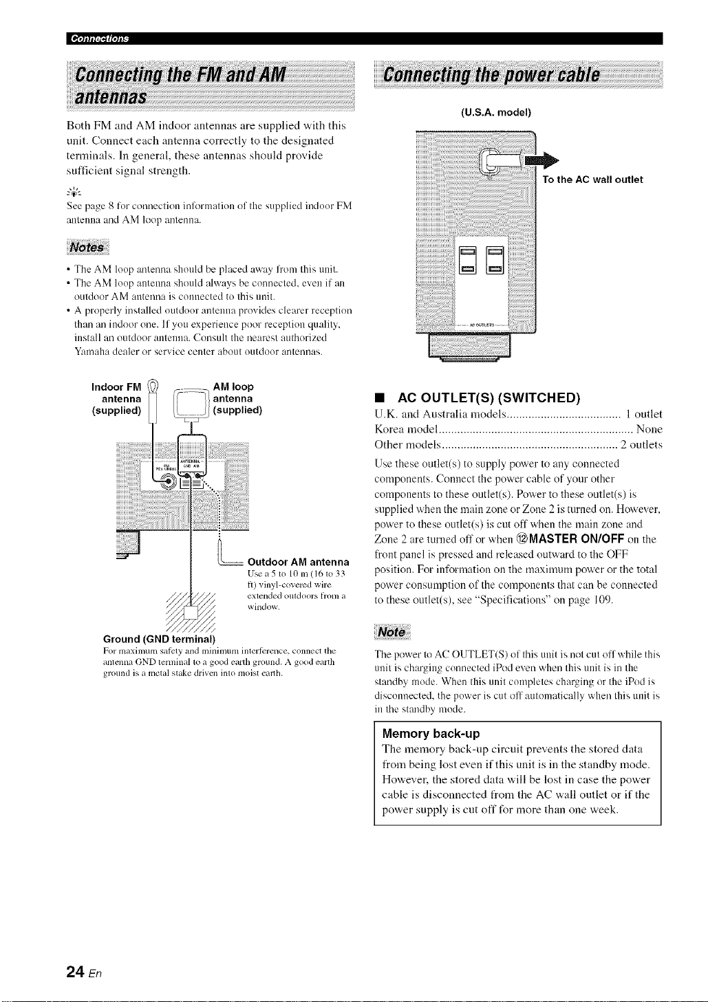
Both FM and AM indoor antennas are supplied with this
unit. Connect each antenna correctly to the designated
terminals. In general, these antennas should provide
sufficient signal strength.
See page 8 htr connection inflwmation of the supplied indoor FM
atttmma and AM loop antemta.
• The AM loop antenna should be placed away l?om this unit.
• The AM loop atttenna should always be connected, even if an
outdoor AM antmma is connected to this unit.
• A properly installed outdoor antenna provides clearer reception
than an indoor one. If you experience poor reception quality,
install an outdoor antenna. Consult the nearest authorized
V:ln]aha dealer or service center about outdoor antennas.
Indoor FM AM loop
antenna antenna
(supplied) ;(supplied)
Outdoor AM antenna
Usea 5m 10 m (161o 3:;
t_)vinyl-co_ercd wire
extended OIl[doors [/'onl a
window.
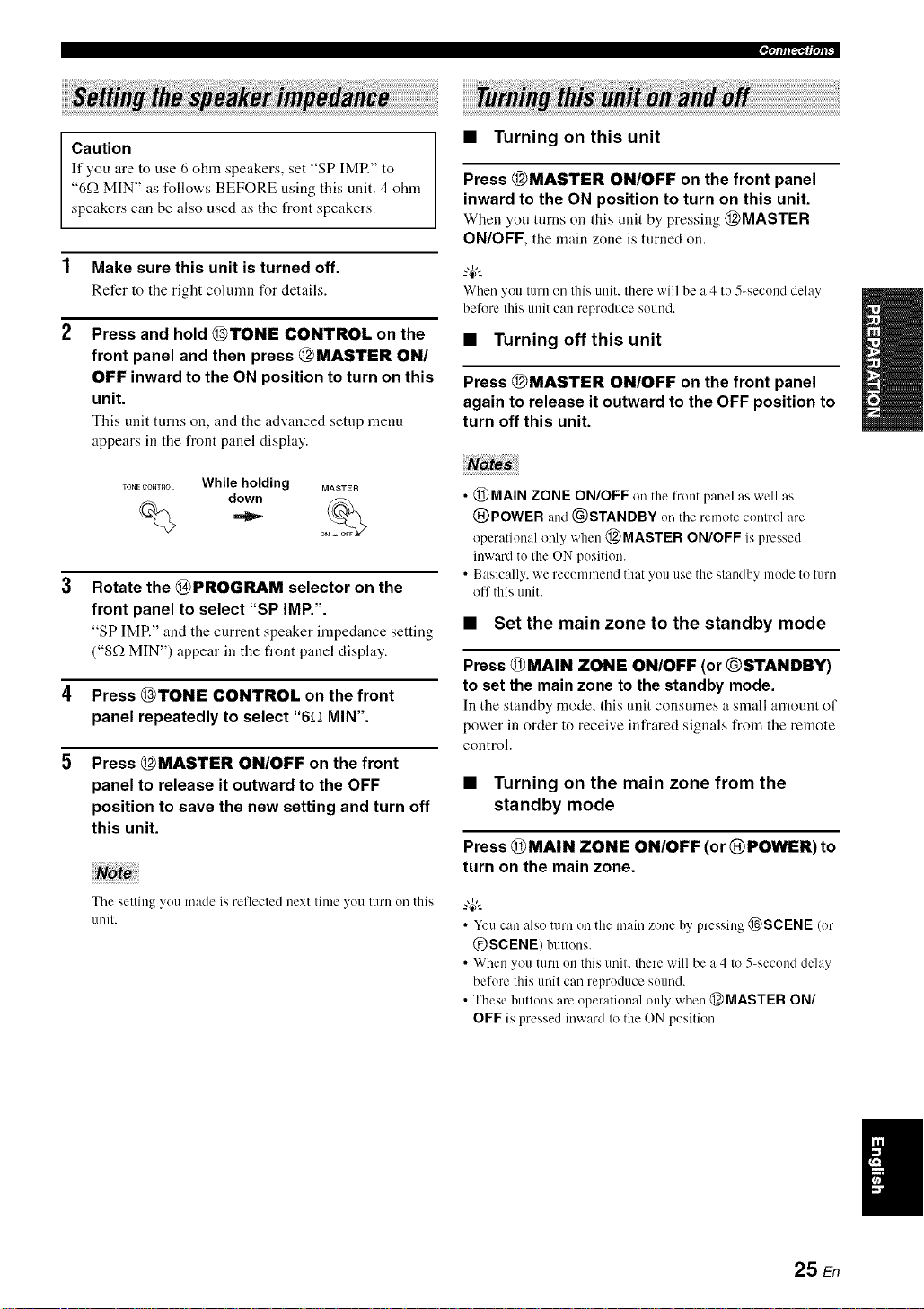
(U.S.A. model)
To the AC wall outlet
• AC OUTLET(S) (SWITCHED)
U.K. and Australia models ..................................... l outlet
Korea model ............................................................... None
Other models ......................................................... 2 outlets
Use these outlet(s) to supply power to any connected
components. Connect the power cable of your other
components to these outlet(s). Power to these outlet(s) is
supplied when the main zone or Zone 2 is turned on. However,
po'a.er to these outlet(s) is cut off when the main zone and
Zone 2 are turned off or when @ MASTER ON/OFF on the
front panel is pressed and released outward to the OFF
position. For information on the maximum power or the total
power consumption of the components that can be connected
to these outlet(s), see "Specifications" on page 109.
Ground (GND terminal)
For maximum sat_ty and mininmm interi_:rence, connect the
antenna (-}ND terminal 1o a good earth ground. A good earth
ground is a metal stake drivcn into nloist ealth.
24 En
The power to AC OUTLET(S) of this unit is not cut off while this
unit is charging connected iPod even when this unit is in the
standby mode. When this unit completes charging or the iPod is
disconnected, the power is cut off atttomatically when this unit is
in the standby mode.
Memory back-up
The memory back-np circuit prevents thestored data
from being lost evenif thisunit is in thestandby mode.
Ho'a,ever, the stored data "a,ill be lost in case the pov,,er
cable is disconnected from the AC wall outlet or if the
power supply is cut oft"for more than one week.
Page 29
,qfff_f|qf_
Caution
If you are to use 6 ohm speakers, set "SP IMR" to
"6f2 MIN" as follows BEFORE using this unit. 4 ohm
speakers can be also used as the front speakers.
1 Make sure this unit is turned off.
Refer to the right colunm for details.
2 Press and hold @TONE CONTROL on the
front panel and then press @MASTER ON/
OFF inward to the ON position to turn on this
unit.
This unit turns on, and tile advanced setup menu
appears in the front panel display.
TO.ECOmROL While holding MASWR
down ,_% -
3
Rotate the @PROGRAM selector on the
o
front panel to select "SP IMP.".
"SP IMP." and the current speaker impedance setting
("8f.) MIN') appear in the front panel display.
4 Press @TONE CONTROL on the front
panel repeatedly to select "6f_ MIN".
5 Press @MASTER ON/OFF on the front
panel to release it outward to the OFF
position to save the new setting and turn off
this unit.
Note
The setting you made is reflected next time yon turn on this
unit.
• Turning on this unit
Press @MASTER ON/OFF on the front panel
inward to the ON position to turn on this unit.
When yon turns on this unit by pressing @MASTER
ON/OFF, the main zone is turned on.
When you turn oi/this unit. there will be a 4 to 5_second delay
belk_rethis unit can reproduce sound.
• Turning off this unit
Press @MASTER ON/OFF on the front panel
again to release it outward to the OFF position to
turn off this unit.
• @MAIN ZONE ON/OFF on the front panel as well as
@POWER and (_)STANDBY oi/the remote control are
operational only when @MASTER ON/OFF is pressed
inward to the ON position.
• Basically, we recommend that you use the standby mode to turn
olT this unit.
• Set the main zone to the standby mode
Press @MAIN ZONE ON/OFF (or @STANDBY)
to set the main zone to the standby mode.
In the standby mode, this unit consumes a small amount of
power in order to receive infrared signals from the remote
control.
• Turning on the main zone from the
standby mode
Press @MAIN ZONE ON/OFF (or @POWER) to
turn on the main zone.
• Youcan also turn on the main zone by pressing _SCENE (or
@SCENE) buttons.
• When you turn on this unit. there will be a 4 to 5-second delay
before this unit can reproduce sound.
• These buttons are operational only when @ MASTER ON/
OFF is pressed inward to the ON position.
25 En
Page 30
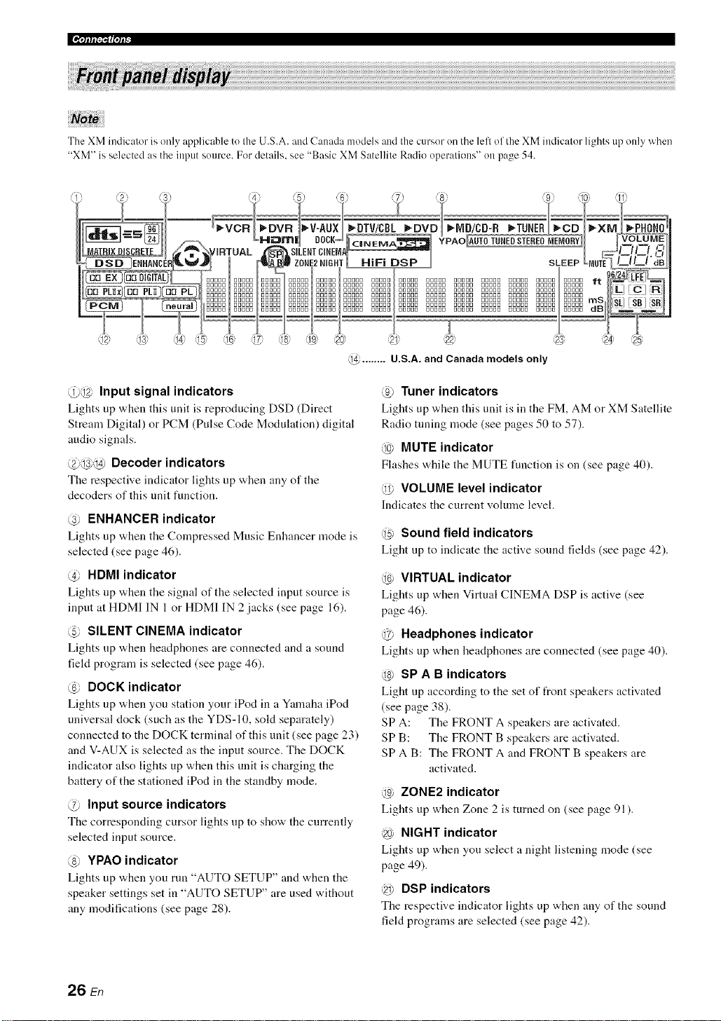
The XM indicator is only applicable to the U.S.A. and Canada models and the cursor oil the left of the XM indicator lights up only when
"XM" is selected as the input source. For details, see "Basic XM Satellite Radio operations" on page 54.
@ ........ U.S.A. and Canada models only
@@ Input signal indicators
Lights up when this unit is reproducing DSD (Direct
Stream Digital) or PCM (Pulse Code Modulation) digital
audio signals.
@@@ Decoder indicators
The respective indicator lights up when any of the
decoders of this unit function.
@ ENHANCER indicator
Lights up when the Compressed Music Enhancer mode is
selected (see page 46).
@ HDMI indicator
Lights up when the signal of the selected input source is
input at HDMI IN 1 or HDMI IN 2 jacks (see page 16).
@ SILENT CINEMA indicator
Lights up v,,hen headphones are connected and a sound
field program is selected (see page 46).
@ DOCK indicator
Lights up "a,hen you station your iPod in a Yamaha iPod
universal clock (such as the YDS-10, sold separately)
connected to the DOCK terminal of this unit (see page 23)
and V-AUX is selected as the input source. The DOCK
indicator also lights up when this unit is charging the
battery of the stationed iPod in the standby mode.
@ Input source indicators
The corresponding cursor lights up to show the currently
selected input source.
@ YPAO indicator
Lights up when you run "AUTO SETUP" and when the
speaker settings set in "AUTO SETUP" are used without
any modifications (see page 28).
@ Tuner indicators
Lights up when this unit is in the FM, AM or XM Satellite
Radio tuning mode (see pages 50 to 57).
@ MUTE indicator
Flashes while the MUTE function is on (see page 40).
@ VOLUME level indicator
Indicates the current volume level.
@ Sound field indicators
Light up to indicate the active sound fields (see page 42).
@ VIRTUAL indicator
Lights up when Virtual CINEMA DSP is active (see
page 46).
@ Headphones indicator
Lights up when headphones are connected (see page 40).
@ SP A B indicators
Light up according to the set of front speakers activated
(see page 38).
SP A: The FRONT A speakers are activated.
SP B: The FRONT B speakers are activated.
SPA B: The FRONT A and FRONT B speakers are
activated.
@ ZONE2 indicator
Lights up when Zone 2 is turned on (see page 91).
@ NIGHT indicator
Lights up when you select a night listening mode (see
page 49).
@ DSP indicators
The respective indicator lights up when any of the sound
field programs are selected (see page 42).
26 En
Page 31

@ Multi-information display
Shows the name of the current sound field program and
other information when adjusting or changing settings.
@ SLEEP indicator
Lights up while the sleep timer is on (see page 41).
@ 96124 indicator
Lights up when a DTS 9(,/24 signal is input to this unit.
@ Input channel and speaker indicators
LFE indicator
,_,a_,_w,2Z,= Presence speaker indicators
['-L] [C---_[Nllnput ch mnel indic tlors
_ _= Stur( und back st eaker indical( rs
LFE indicator
Lights up when the input signal contains the LFE
signal.
Input channel indicators
Indicate tile channel componeuts of tile current digital
input signal.
Presence and surround back speaker
indicators
Light up according to the number of presence and
surround back speakers set for "EXTRA SP ASSIGN"
(see page 72) and "SUR.B L/R SP" (see page 73) in
"SOUND MENU" when this unit is in the auto setup
(see page 28) or the speaker level setting in "SOUND
MENU" (see page 74) procedure.
_%,._
• You can make settings for surround back speakers autonlatically
by running "AUTO SETUP" (see page 28) or manually by
at{jnsting settings for "SUR.B L/R SP" (see page 73) in
"SOUND MENU".
• To use the presence speakers, set "EXTRA SP ASSIGN" to
"PRESENCE" (see pages 29 or 72).
.qftf[ff1¢|'tf_-
The remote control transmits a directional infrared ray.
Be sure to ailn the remote control directly at the remote
control sensor on this unit during operation.
Remote control sensor
I
0000
/
Approximately 6 m (20 ft)
€
Infrared window (@)
Outputs infrared control signals. Aim this window at tile
component you want to operate.
@TRANSMIT indicator
Flashes "a.llile tile remote control is sending infrared
signals.
Operation mode selector (@)
The fuuction of some buttons depends on tile operation
mode selector position.
AMP
Operates the amplifier function of this unit.
SOURCE
Operates tile component selected with an input
selector button (see page 87).
TV
Operates the TV assigned to either DTV/CBL or
PHONO (see page 86).
• Do not spill water or other liquids on the remote control
• Do not drop the remote controh
• Do not leave or store the remote control in the lbllowing types
of conditions:
places of high humidity, such as near a bath
places of high temperatures, such as near a heater or stove
places of extremely low temperatures
dusty places
• To set the remote control codes for other components, see
page 88.
27 En
I
Page 32

This unit employs the YPAO (Yamaha Parametric Room Acoustic Optimizer) technology which lets you avoid
troublesome listening-based speaker setup and achieves highly accurate sound adjustments alltomatically. The supplied
optinfizer microphone collects and this unit analyzes the sound your speakers produce in your actual listening
environnlent.
2
Connect the supplied optimizer microphone
to the OPTIMIZER MIC jack on the front
Notos
• Be advised that it is normal lor hind test tones to be output
during the "AUTO SETUP" procedure.
• To achieve the best results, make sure the room is as quiet as
possible while the "AUTO SETUP" procedure is in progress. If
there is too much ambient noise, the results may not be
satisfactory.
panel.
"4¢:
• You can run "AUTO SETUP" using the systmn menu thal
appears in the OSD or in the front panel display. This manual
uses the OSD illustrations to explain the "AUTO SETUP"
procedure.
• Belkweperlonning operations, set the operation mode selector
on the remote control to (_)AMP.
• This unit uses the speakers connected to the FRONT A speaker
terminals as the front speakers lk_rthe a@lstment.
Make sure of the following check points
before starting the AUTO SETUP operations.
[21 Speakers are connected appropriately.
[21 Headphones are disconnected from this unit.
[21 This unit and the video monitor are turned on.
[21 The connected subwoofer is turned on and the
volume level is set to about half way (or slightly
less).
[21 The crossover frequency controls of the
connected subwoofer is set to the maximum.
[21 The room is sufficiently quiet.
.....................................I_ microphone
The follovdng menu screen appears on the video
monitor.
gLl_ O_IqENU
÷ EXTRA 5F' PSSIGH
ZCllqlE2 ::FROHT B
F'RESEIE:E HOHE
SETUP, ...... I:ILITO
E¢!....... 140TURJ:IL
STPRT
[_]![>]_Seiect
Place the optimizer microphone at your
normal listening position on a flat level
surface with the omni-directional
microphone heading upward.
Optimizermicrophone
Omni-directional
28 En
It is recommended that you use a tripod (etc.) to affix the
optimizer microphone at the same height as your ears would
be when you are seated in your listening position. You can
use the attached screw of a tripod (etc.) to fix the optimizer
microphone to the tripod (etc.).
Page 33

4
Press @<1 / L> to select the desired setting
for "EXTRA SP ASSIGN" and then press @V.
)l_ltllllt41allldal:l_._l,I:_.l;(;lJ.'_;l_'J[_Yl, l#lBi_(_!allalligeI,11i
Press @<1/_> to select the desired setting of
"EQ".
Extra speaker assignment
i::?=...:T_:::u"_ ,::?i::) _"K:?,::? T _':::M
Selects the function of tile speakers connected to the
EXTRA SP terminals.
Choices: FRONT B, ZONE2, PRESENCE, NONE
• When you use the alternative front speaker
system (see page 38)
Select "FRONT B".
• When you use the Zone 2 speakers (see
page 91)
Select "ZONE2" to set the function of the speakers
to the Zone 2 speakers. This unit drives the Zone 2
speakers by using the internal amplifier.
• When you use the presence speakers (see
page 12)
Select "PRESENCE" to set the function of the
speakers to the presence speakers.
• When you do not use the EXTRA SP
terminals
Select "NONE" to deactivate the EXTRA SP
terminals.
11you select "ON" in "BI-AMP" (see page 96), you cannot
selecl "PRESENCE" or "ZONE2" in "EXTRA SP
ASSIGN".
Parametric equalizer type E(;!
Parametric equalizer adjusts the level of the specified
frequency bands. This unit automatically selects the
crucial frequency bands for the listening root]] and
adjusts the level of the selected frequency bands to
create a cohesive sound fiekt in the room. You can
select the type of the parametric equalizer adjustment
from the following choices.
Choices: NATURAL, FLAT, FRONT
• Select "NATURAL" to average out the frequency
response of all speakers with higher frequencies
being less emphasized. Recommended if the FLAT
setting sounds a little harsh.
• Select "FLAT" to average the frequency response
of all speakers. Recommended if all of your
speakers are of similar quality.
• Select "FRONT" to adjust the frequency response
of each speaker in accordance with the sound of
your front speakers. Recommended if your front
speakers are of much higher quality than your other
speakers.
Press @V to select "START" and then press
(_IENTIER to start the setup procedure.
This unit starts the auto setup procedure. Loud test
tones are output from each speaker during the auto
setup procedure. Once all items are set, the
"AUTO:RESULT" display appears in the OSD.
Press @<1 / E>to select "SETUP" and then
press @_.
Choices: AUTO, RELOAD, UNDO, DEFAULT
• Select "AUTO" to automatically run the entire
"AUTO SETUP" procedure.
• Select "RELOAD" to reload the last "AUTO
SETUP" settings and override the previous
settings.
• Select "UNDO" to undo the last "AUTO SETUP"
settings and restore the previous settings.
• Select "DEFAULT" to reset the "AUTO SETUP"
parameters to the initial factory settings.
• "RELOAD" or "UNDO" is axailable only whet] you have
previously run "AUTO SETUP" and confirmed the results.
• "RELOAD" or "UNDO" is not available when you change
the setting of "BI-AMP" in the advanced setup (see
page 96) or "EXTRA SP ASSIGN" in "SOUND MENU"
(see page 72).
• During the auto setup procedure, do not perform any
operation on this unit.
• We recommend that you get out of the room while this unit
is in the auto setup procedure. It takes approximately 3
minutes for this unit to complete the atttu setup procedure.
29 En
Page 34

This unit performs the following checks:
Speaker wiring t,ii F;;:]IMG
Checks which speakers are connected and tile
polarity of each speaker.
Speaker size $ iZE
Checks the frequency response of each speaker and
sets the appropriate low-frequency crossover l\_r each
channel.
Speaker distance i-,T(::'"r,",M,".i::2
Checks the distance of each speaker from the
listening position and adjusts the timing of each
channel.
Equalizing _:::.,.-,i_,...,_'r"::=Tid,::
Checks and adjusts the tonal characteristics of all the
speakers by the setting of"EQ".
Speaker level i i::2iii:::.i
Checks and adjusts the vohnne level of each speaker.
The display changes as %llows:
gUT0=REHU
E',qTRAL:PPSSiGM
ZCIIJE2>FROIqTB
F'RESEIfiCE HOHE
SETLIF'. ...... AUTO
EL_!....... IqATtlR#L
+ ST#RT
r,_.] [ ',r] _UF'[,o_,_n
D4] '[_'] _S,.=]eci.
!
gl_lTO_ C:HEC:}:
INITIIqI_IZilqg
+ i,]lRllqg
51ZE!DISTgHCE
EQLIRLIZ iIqG
LEUEL
CHEL-:K L-:H=CEHTER
iiiil ........
The results displayed under "RESULT" are as
l\)llows:
Number of speakers :!!!;l:::'
Displays the number of speakers connected to this
unit in the following order:
Front/Back/Subwoofer
Speaker distance DIS"[
Displays the speaker distance from tile listening
position in the following order:
Closest speaker distance/Farthest speaker distance
Speaker level LJ...iJ....
Displays the speaker output level in the following
order:
Lowest speaker output level/Highest speaker output
level
• If "E-10:INTERNAL ERROR" appears during the testing
procedure, restart from step 4.
• If you selected other than "AUTO" in step 5, no test tones
are output.
• If an error occurs during the "AUTO:CHECK" procedure.
the setup procedure is canceled and an error screen
appears. For details, see "If an error screen appears" on
page 32.
• When this unit detects potential problems during the
"AUTO SETUP" procedure. "WARNING" and the
number of warning messages appears in the above of
"RESULT" (see page 32).
• Depending on the listening environment. "SWFR
PHASE:REV" appears during the "AUTO:CHECK"
procedure and "SUBWOOFER PHASE" in "SOUND
MENU" (see page 74) is automatically set to
"REVERSE".
Press @/\ and then @ENTER to display the
setup results in detail.
30 En
I_UTO:'RESULT
RESULT
SF' _ 3,4/0, i
DiST_ 14. L],'i7.L]ft
LUL _ -'?,g'+B,5dB
+ ?EET CAI%-:EL
[ ENTER ] _ Er,<:er
gLITO_RESULT
RESUI_T
SP _ 3,'4/_?_i
DiST_ 14 J?/17 J_,f L
LUL ; .-'?,n'_6,5dB
)SET CAHCEI_
[_] ,[T] _UF '[/c,t,_r,
[ EHTER ] ::Epter
RESULr_,_IR11,4G
FR011TL. ...... OK 1
[4]i[_]_Select
[EIq_ER] _Return
T
Page 35

)1171_llllt'41allldal:lt._l_I:_.ll(;lJ.'_:l_lffffJ[_'l_1#lBi_(;lallallIgeI_11i
Press @<1 / E> repeatedly to toggle between
the setup result displays.
Press (_)A / V to toggle between the parameters in a
results.
==_ Results of the speaker
connection and wiring
Results of the speaker
distance from the
listening position
Results of the setting of
each speaker size
Results of the parametric
equalizer of each speaker
10 Press @IENTIER to return to the top
"AUTO:RESULT" display.
gLITCl_RESLILr
RESLILT
SF' _ 3/4/0, t
DIST: t4_0, t7_O?t
LL!L _ .-9,0/+6,,5dB
?¸SET C:glqCEL
[±] ,, Iv] _LIF,,Do_r,
[ EI'_TER] _=Enter ¸
11 Make sure the pointer is pointing at "SET"
and "CANCEL" and then press (_)<1 / c> to
select "SET" or "CANCEL".
AUT0_ RESULT
RESULT
SF' _ :_,4/0,l
DiST; 14_0,17_0;t
LUL _ -9_0'+6_5dE'
÷ ?SET C:AI'IC:EL
[&] ['_']_=UF 'Dc,_,:r,
[ El'IT ER] _Enter
Choices: SET, CANCEL
• Select "SET" to confirm the "AUTO SETUP"
results.
• Select "CANCEL" to cancel the "AUTO SETUP"
results.
Results of the speaker
output level
If you are not satisfied with the results or want to manually
a_/iust each parameter, use "MANIJAL SETUP" (see
page 69).
• The distances displayed in the "DISTANCE" results may
be longer than the actual distance depending on the
characteristics of your subwoofcr.
• In the "EQ" results, different values may be set lor the
same frequency to provide finer adjustments.
12 Press @IENTIER to confirm your selection.
The top "SET MENU" display appears in the OSD.
SET MEI'4U
÷ ,13LITOSETLIF'
,MAIIUAL SETLIF'
,S IGI'IAL II'IFO
[A] / [',_] _UF ![,o_m
[ EIq]ER] _Enter
13 Press @$1ET MIENU to exit from "SET
MENU".
14
Disconnect the optimizer microphone from
this unit.
The optimizer microphone is sensitive to heat. Keep it
away from direct sunlight and do not place it on top
of this unit.
"4':
If you change speakers, speaker positions, or the Iwout of
your listening environment, run "AUTO SETUP" again to
recalibrate your system.
I
31 En
Page 36

• If an error screen appears
Press @A / V / <1/ _> to select "RETRY" or
"EXIT" and then press @ENTER.
The follov4ng display is an example when "E-9:USER
CANCEL" appears in the OSD.
gUT0_ ERRCIR
÷ E-9_LISER C:AH[:EL
_rl_l _urlc { iorh,
?RE',rRV E:,,IT
D"a]'[> ]_Sei ect
EHTER ]:Enter
Choices: RETRY, EXIT
• Select "RETRY" to retry the "AUTO SETUP"
procedure.
• Select "EXIT" to exit from the "AUTO SETUP"
procedure.
• If"WARNING" appears
When this unit detects potential problems during the
"AUTO SETUP" procedure, "WARNING" appears in the
"AUTO:RESULT" display. Check the warning messages
to correct your speaker settings.
Press @<1 / C>repeatedly to toggle between
the warning displays.
WgRI41IqG: W- 1
<OUT [IF F'HI:4SE>
ee,!el' :=.e Charlrle i
FL --
C:EI,ITER
F'L PR
SL SR
SBL SBR
['a] '[> ] _Select
['ENTER ];Return
•Fordetails about each warning message, see the "AUTO
SETUP" sectionin "Troubleshooting" on page 102.
• When thecorresponding warning messageis not
applicable to aspeaker, " -' is displayed instead.
Press (_IENTIER to return to the top
"AUTO:RESULT" display.
Warnings dilfer from errors in that warnings do not cancel Ihe
"AUTO SETUP" procedure.
Make sure the pointer is pointing at
"WARNING" and then press @ENTER to
display the detailed information about the
warning.
The number on the right of "WARNING" indicates
the nmnber of warning messages.
gLITOaRESUL,T
WPRI4i HG(3:,
RESULT
SP : 3'4'_, 1
DiST: 14.g!17,Of{
LUL : -9.6/+6.5d[?
?SET [:I:IHCEL
[±] !IT] : LIFibc,_,:r,
[ ENTER ]; Enter
32 En
Page 37

This unit is equipped with 18 preset SCENE templates for
various situations of using this unit. As the initial factory
setting, the following SCENE templates are assigned to
each SCENE button:
SCENE 1: DVD Viewing
SCENE 2: Disc Listening
SCENE 3: TV Viewing
SCENE 4: Radio Listening
If you want to use other SCENE templates, you can select
the desired SCENE templates from the SCENE template
library and assign the templates to the selected SCENE
buttons on the front panel and the remote control.
Select the desired SCENE
template
2 Rotate the @INPUT selector (or set the
operation mode selector to @AMP and then
press (_<3 / C>) to select the desired
template.
3 Press the @SCENE (or @SCENE) button
again to confirm the selection.
The selected SCENE template is assigned to the
SCENE button.
or
Assign the
SCENE
SCENE template library
(Image)
template to the
SCENE button
Press and hold the @SCENE (or ®SCENE)
button for 3 seconds.
The indicator on the selected SCENE button on tile
front panel starts to flash, and the name of the
currently assigned SCENE template appears in the
front panel display.
3 seconds 3 seconds
or
Q
Front panel
Remotecontrol
Front panel
• If you do not carry out any operation within 30 seconds
l?om the last operation in these steps, this procedure is
automatically canceled.
• Once the desired SCENE templates are assigned to the
corresponding SCENE buttons, you need to set the input
source of the SCENE template on the remote controh See
pa_e 85 lot details.
Remote control
Flashes
L-'_..-'L. -= _..-" .i. l:::=i.=..=.i. i" i':::=
33 En
Page 38

• Which SCENE template would you like to select?
Which source do you like to
o{
play back?
Video sources
(DVD video,
Recorded video)
Music discs (CD,
SACD or DVD-Audio)
Radio programs
Which component do you
like for playback?
DVD
DVR
DVD
CD
TUNER (FM/AM)
XM
' To ei_joy XM Satellite Radio programs, you need to
connect the XM Mini-Tuner Dock (sold separately) and
SCENE templates
DVD Viewing
DVD Movie Viewing
DVD Live Viewing
DVR Viewing
Disc Hifi Listening
Music Disc Listening
Disc Listening
CD Hifi Listening
CD Listening
CD Music Listening
Radio Listening
XM Listening
Default
SCENE buttons
©
iPod DOCK iPod Listening
To listening Io the iPod, you need to connecl a Yamaha
iPod universal dock (sold separately) to this unit
(see page 58).
_/{ TV programs ]_/_ DTV/CBL TV Viewing
TV Sports Viewing
games
_,{ Video t_/_[ V-AUX Action Game Playing
RPG Playing
Vinyl records PHONO LP Record Listening
You can creale your original SCENE templates by editing the preset SCENE lemplates. See I _.e ( 1 r de alls.
i
i
i
i
i
34 En
Page 39

• Preset SCENE templates descriptions
Tile illustrations of tile SCENE button in the following table indicate tile assigned SCENE buttons in tile default setting.
SCENE template
DVD Movie Viewing
DVD Live Viewing
DVR Viewing
Disc Hifi Listening
Music Disc
Listening
Input source
DVD*I
DVD*I
DVR
DVD*I
DVD*I
Playback mode
MOVIE
Sci-Fi
ENTERTAINMENT
Music Video
MOVIE Drama
PURE DIRECT
STEREO
2ch STEREO
Select this SCENE template when you play back movies on
your DVD phlyer.
Select this SCENE template when you enjoy the music live
video on your DVD player.
Select this SCENE template when you play back movies on
your digital video recorder.
Select this SCENE template when you enjoy the high
fidelity sound of the music discs on your DVD player.
Select this SCENE template when you play back music
discs on your DVD player.
Features
Disc Listening DVD*I STEREO Selectthis SCENEtemplatewhenyouplay backmusic
___ 7oh STERE°
CD Hifi Listening
CD Listening
CD Music Listening
CD*I
CD*I
CD*I
PURE DIRECT
STEREO
2ch STEREO
STEREO
7ch STEREO
Select this SCENE template when you enjoy the high
fidelity sound of the music discs on your CD player.
Select this SCENE template when you play back music
discs on your CD player.
Select this SCENE template when you play back music
source on your CD player as the background music.
Radio Listening TUNER MUSIC Select this SCENE template when you enjoy FM 0r AM
I I ENHANCER radio Programs.
XM Listening
iPod Listening
TV Sports Viewing DTV/CBL
Action Game V-AUX .2
Playing
RPG Playing V-AUX .2
LP Record Listening PHONO
When the connected DVD pla_er or ('D player has the
capability of the SCENE control signals and is connected to
the REMOTE OUT jack of this unit. this unit operates the
DVD player or CD player worked with the SCENE features.
XM
DOCK (V-AUX)
I 7Ch Enhancer i
MUSIC
ENHANCER
7ch Enhancer
MUSIC
ENHANCER
7ch Enhancer
ENTERTAINMENT Select this SCENE template when you enjoy sports
Sports programs on your TV.
ENTERTAINMENT Select this SCENE template when you play action games
Action Game such as car racing and FPS games.
ENTERTAINMENT Select this SCENE template when you play role-playing
Roleplaying Game games.
PURE DIRECT Select this SCENE template when you play back vinyl
Select this SCENE template when you enjoy XM Satellite
Radio programs.
Select this SCENE template when you play back music on
your iPod stationed in a Yamaha iPod universal dock.
records on your turntable.
'2 You can select "V-AUX" as the input source even if your iPod
is stationed in the Yamaha Universal Duck connected to this
unit.
I
35 En
Page 40

You can create your original SCENE templates for each
SCENE button. You can refer to the preset 18 SCENE
templates to create the original SCENE templates.
Select the desired SCENE
template
SCENE template library
(Image)
Create an original SCENE
template
Assign the SCENE
template to the
SCENE button
1 Turn on the video monitor connected to this
unit.
2 Set the operation mode selector to @AMP
and then press and hold the desired
@SCENE button for 3 seconds.
The SCENE template customizing screen appears on
the video monitor.
÷._ DIll) i ]i @t,/j4"l'_ I_
iI4PIJT: DUD
blCIDE;: STRglIGHT
TI- T - -T-t4_-_H,. =,, z,, LI]
:El ITER ];IRen_he
[ RETURIq ] _ I-TI:ITI_!I-
When the SCENE template you want to customize is not
assigned to ally of the @SCENE buttons, press @<1 / _>
repeatedly to recall the desired SCENE template on the
nlenLi screen.
Press @A / V to select the desired parameter
of the SCENE template and then @<1 / c> to
select the desired value of the selected
parameter.
You can adjust the following parameters for a SCENE
template:
• INPUT: The input source component.
• MODE: The active sound field programs,
STRAIGHT or Pure Direct mode.
• NIGHT: The night listening mode (see page 49).
SYSTEM: Keeps the current night listening
mode.
CINEMA: Sets the night listening mode to the
CINEMA mode.
MUSIC: Sets the night listening mode to the
MUSIC mode.
4 Press the @SCENE button again to confirm
the edit.
An asterisk mark (*) appears by the name of the original SCENE
template,
• Once the desired SCENE templates are assigned to the
corresponding @SCENE buttons, you need to set the input
source of the SCENE template on the rmnote controh See
page 85 lk_rdetails.
• You can create a customized SCENE template lor each SCENE
button, and if you create another customized SCENE template.
this unit overwrites the old customized SCENE tmnplate with
the new one.
• The newly created template is only :r_*ailablelk_rthe assigned
SCENE button.
• Renamethe SCENE templates
Select the name of the SCENE template at step 3
of "Creating your original SCENE templates" and
then press @ENTER.
• Press @A / V to select tile desired character.
• Press @<1 / Ii:>to place an .... (underscore) under the
space or the desired character.
• Press @RETURN to cancel the new name.
• Press @ENTER to confirm the new name.
36 En
Page 41

Caution
Extreme caution should be exercised when you play
back CDs encoded in DTS. If you play back a CD
encoded in DTS on a DTS-incompatible CD player,
you will only hear some unwanted noise that may
damage your speakers. Check whether your CD player
supports CDs encoded in DTS. Also, check the sound
output level of your CD player before you play back a
CD encoded in DTS.
_%,._
To play [)TS-encoded CDs when using a digital audio
commctiou, set "DECODER MODE" in "INPUT MENU" to
"DTS" before the playback (see page 80).
Befl)re performing the %llowing operations, set the operation
mode selector on the remote control to @AMP.
Turn on the video monitor connected to this
unit.
See page 40 to display the input source inhwmation on the
video monitor.
Start playback on the selected source
component or select a broadcast station.
• Refer to the operating instructions for tile source
component.
• See page 50 for details about tuning instructions.
• See page 54 for details about XM Satellite Radio
tuning instructions.
Rotate @VOLUME (or press @VOLUME +/-)
to adjust the volume to the desired output
level.
• See page 48 to acliust the level of each speaker.
• This does not affect the AUDIO OUT (REC) level.
• You can set the initial volume level and maximum volume
level (see page 77).
Rotate the @ PROGRAM selector (or press
one of the sound field program selector
buttons ((_)) repeatedly) to select the desired
sound field program.
The name of tile selected sound field program appears
in the front panel display. See page 42 for details
about sound field programs.
2
Rotate the @INPUT selector (or press one
of the input selector buttons (@)) to select
the desired input source.
The name of the currently selected input source
appears in the front panel display for a few seconds.
Available input sources
i vcR Dw v-Aux DW/CBL_DVD _D,_D R TU_E_ CD XM PH_0_I
.i.i"..=i"- LJ i == L."=='.'=L.'=I
Currently selected input
source
The corresponding input selector button on the remote
control lkwthe currently selected input source lights up for
approximately 5 seconds after you press any buttons on the
remote control, showing which source component is
currently being operated.
,:;7.-..; -..iZ" .;
....==.. & _ &
Currently selected sound field program
%
/
Sound field programs canuot be selected when the
component connected to the MULTI CH INPUT jacks is
selected as the input source (see page 38).
_%,._
• Choose a sound field program based on your listening
preference, not merely on the name of the program.
• When you select an input source, this unit automatically
selects the last sound field program used with the
corresponding input source.
• To display information about the currently selected sound
field program in the OSD, see page 61 lor details.
37 En
Page 42

l$/,_,'g=t
• A quick guide to contents
When you want to...
Enjoy pure hi-fi stereosound 48
A_!justtile tonal quality of the front speakers 48
A(!justthe parameters of sound field programs 61
Enjoy sources with a wide dynamic range at night 49
Use headphones 40
Enjoy multi-channel sources in 2-channel stereo 49
Select a decoder to play back sources with 66
Automatically set this unit to the standby mode 41
Use this feature to select the component connected to the
MULTI CH INPUT jacks (see page 22) as the input
source.
Rotate the @INPUT selector to select MULTI CH
(or ®MULTI CH IN).
"MULTI CH" appears in the front panel disphty.
See
page
_%,._
Use "MULTI CH SET" mmm in "INPUT MENU" to set the
parameters Ii_r MULTI CH INPUT (see page 80).
Note
Sound field programs and the night listening mode cannot be
selected when the component connected to the MULTI CH
INPUT .jacks is selected as the input source.
Use this feature to turn the front speaker system (FRONT
A and/or FRONT B) on or oft'.
Press @SPEAKERS on the front panel
repeatedly to turn on or off the set of front
speakers connected to the FRONT A and/or
EXTRA SP speaker terminals.
The active front speaker set changes as follo'a,s.
I FRONT A____ FRONT B l
OFF (--- and
• FRONT A and B or FRONT B setting is not available when
"EXTRA SP ASSIGN" is set to "PRESENCE". "ZONE 2" or
"NONE" (see page 72).
• Turn olT the vohmm level of this unit when you switch the lhont
speaker setting.
FRONT A
FRONT B
• Using the Zone B feature
When you set "FRONT B" to "ZONE B" (see page 72),
you can use the speakers connected to the EXTRA SP
speaker terminals in another room (Zone B).
Press @SPEAKERS on the front panel
repeatedly to turn on or off the Zone B speakers.
When you activate the Zone B speakers, all the speakers in
the main room are muted.
• You cannot actNate both the main room and Zone B speakers
simultaneously.
• If you select CINEMA DSP sound lield program and activate
the Zone B speakers. Virtual CINEMA DSP activates
automatically (see page 46).
38 En
Page 43

_O'v,',m-._;
This unit comes with a variety of input jacks. Use this
feature (audio input jack select) to switch between input
jacks when more than one input jack is assigned to the
same input source.
• We recommend that you set the audio input jack select to
"AUTO" in most cases.
• You can adjust the del:mlt audio input jack select of this unit by
using "AUDIO SELECT" in "OPTION MENU" (see page 83).
Press @AUDIO SELECT (or @AUDIO SEL)
repeatedly to select the desired audio input jack
select setting.
Available input sources
I vcR Dw wAux DWiCSL_OW MDICD-R TU_ER ¢D XM PHON
iI:::l.. ':::;]:::] :: I:::I]rT'_"l_
Currently selected audio input jack select setting
174U"['0 Automalically selects input signals in the
i=.ir'.,i.,.i"r Selects only HDMI signals. When HDMI
i IL,='I I,L •
,....,...,r"_,",.'mm_"_""...mOT,...,__ Automalicallv selects input signals in the
r'H..i_"_imm Selects only analo_ Si_llals. If no aoalo_
lk)llowing order: (1) HDMI (2) Digital
signals (3) Analog signals.
signals are nol inpul, no sound isoutput.
lk)llowing order: (1) Digital signals input
at the COAXIAL jack. (2) Digital signals
inpul at the OPTICAL jack. When no
signals are input, no sound is outpul.
signals are input, no sound is outpul.
You can display the operating information of this unit on a
video monitor.
1 Turn on the video monitor connected to this
unit.
2 Set the operation mode selector to @AMP
and then press (_DISPLAY on the remote
control.
The current status screen appears in the OSD.
5TI?TLIS UOL _-4€_,, €_dB
M[ll,JI E
5ci-gi
i HPLIT: DUD
IZl,,SEL _ HI)I,1i
HIGHT; OFF
You can select the amount of time that the current status is
displayed in the OSD by using the "OSD-AMP" parameter
in "OPTION MENU" (see page 82).
The OSD signal is nol output al the VIDEO output jacks and
will nol be recorded.
This li:ature is not available when no digital input jacks
(OPTICAL. COAXIAL and HDMI) are assigned. In addition.
HDMI is i_otavailable as an audio input jnck select setting when
the HDMI IN l and HDMI IN 2jacks are not used. Use "I/O
ASSIGNMENT" in "INPUT MENU" to reassign the respective
input jack (see page 78).
39 En
Page 44

Connect a pair of headphones with a stereo
analog audio cable plug to the PHONES jack on
the front panel.
When you select a sound field program. SILENT CINEMA mode
activales automatically (see page 46).
Noto :
• When you connect headphones, no signals are output at the
speaker terminals.
• All Dolby Digital and DTS audio signals are mixed down to the
left and right headphone chatmels.
You can combine a video image from a video source with
sound from an audio source. For example, you can enjoy
listening to classical music while viewing beautifld
scenery from the video source on the video monitor.
Press the input selector buttons (@) on the
remote control to select a video source and then
an audio source.
Audio sources--
Video sources--
Set the "BGV" parameter in the "MULTI CH SET" menu to the
desired setting to select the del:mlt background video input source
of the MULTI CH INPUT sources (see page 80).
You can display the format, sampling frequency, channel,
bit rate and flag data of the current input signal.
Press @MUTE on the remote control to mute the
audio output.
Press @MUTE again to resume the audio output.
--T--
• You can also rotate @VOLUME on the front panel or press
@VOLUME +/- to resume the audio output.
• You can adjust the muting level by using the "MUTE TYPE"
parameter in "SOUND MENU" (see page 76).
• The MUTE indicator flashes in the front panel displ W when the
audio output is muted and disappears Dora the front panel
display when the audio output is resumed.
Set the operation mode selector to @AMP
and then press @SET MENU on the remote
control.
The top "SET MENU" disphty appears in the OSD.
SET HEHLI
+ ,IqLITCI SETUP
,MI:IMLIIOLSETLIP
,SiS_I_L IHFO
[ EI4_ER ] ; Enter
Press @V repeatedly to select "SIGNAL
INFO" and then press @ENTER.
The audio information about theinput sourceappears
in the OSD.
3 Press (_)<_/_> to toggle between the audio
and video information displays.
4 Press @SET MENU on the remote control
again to exit from "SET MENU".
40 En
Page 45

• Audio information
i=<¢=li:::'h'i¢"I"i_ Si_[l;[] format. \¥hcn tlJS Ul]il Lal]l]Ot dLqcct a
digila] signal, il aulonmtically swilchcs Io
analog input.
....,::,"Mviii:)i,r..ll,_...._.H,..._'r;.i_'::: Tile number of samples per second taken l¥om
a conlinuous signal Io make a discrete signal.
,...ql=q"Ji"d"ii"ii::rilr"lH l "ll...l .... Tile number of sou rcc channels in tile inpul
signal (fionUsurround/LFE). For example, a
mulli-channel soundtrack wilh 3 front
clmnnels, 2 surround channels and LFE, is
displayed as "3/2/0.1L
_...,i::'a.T<'i"i:::,,"¢ri:::'_v..r'<,__.... Tile number of bits passing a given poilll per
second.
i:::i_...r......_r.'::: Flag dala encoded in DTS, Dolby Digital, or
PCM signals thai cue Ihisunil toautomalically
switch decoders.
Set the operation mode selector to @AMP and
then press @SLEEP repeatedly to set the
amount of time.
Each time you press @SLEEP, the front panel display
changes as shown below.
The SLEEP indicator flashes while you are switching the
amount of time for the sleep timer. Once the sleep timer is
set, the SLEEP indicator lights up in the front panel
display, and the display returns to the selected sound field
program.
Flashes
.... appears when this unit cannot display the corresponding
information.
• Video information
" li"J i"_i','iI I...<I I "l'.l....i_::' Z.l.i...l Ii_:: i.. h"i i_ I"I I..... ' Type of tilL' source video signals and lilt..
video signals outputal the HDMI OUT
jack of Ihis unit.
li"Ji"d','i_i...<_la.T _'.._........,i=,i=',2::=: Resolution of the inpul sigl]al (analog or
HDMI) and Ihe oulput signal (HDMI).
When inpul video siglmls are composite
vkleo or S-video signals, the inpul video
sigl]als are indicaled as "Comlx)sile" or
"S-Video'.
iq[:'Mi i!!!?:;?.i:;;:0i:;?.Error message for HDMI sourcesor
connecled HDMI devices. See page 102
for demils.
.... appears when this unit calmot display the corresponding
information.
Use this feature to automatically set the main zone to the
standby mode after a certain amount of time. The sleep
timer is useful when you are going to sleep while this unit
is playing or recording a source. The sleep timer also
automatically turns off any external components
connected to the AC OUTLET(S) (see page 24).
¢" i r" r" i": ,i ,": i":i .... : ,.
,%1 I,,, I,,, I,,, I ,, h,l III I I'I
...., i,,,, i,,,, i,,,, i ,i, ,i,,, ,,,,, i i ,i, I I
#
Lights up
....: if'::_i-i i i"ii"i i
• Canceling the sleep timer
Press @SLEEP on the remote control repeatedly
until "SLEEP OFF" appears in the front panel
display.
Disappears
i::::L..i:::.i:::.i.... L.ii" i"
The SLEEP indicator turns off, and "SLEEP OFF"
disappears from the front panel display after a few
seconds.
The sleep timer setting can also be canceled by pressing
@STANDBY (or @MAIN ZONE ON/OFF) to set the main
zone to the standby mode.
Even if this unit is it] the standby mode. this unit does not cul ofl
the power Io AC OUTLET(S) while charging connected iPod
(see page 24).
!1
41 En
Page 46

This unit is equipped with a variety of precise digital decoders that allow you to enioy multi-channel playback from
almost any stereo or nmlti-channel sound source. This unit is also equipped with a Yamaha digital sound field processing
(DSP) chip containing several sound fiekt programs which you can use to enhance your playback experience.
_%,._
• The Yamaha HiFi DSP sound field programs recreate real-world acoustic environments made frunl precise nmasurmnents taken in
actual concert halls, music venues, movie theaters, etc. Thus. you may notice variations in the strength of the reflections coming l?'om
the front, back. lefi and right.
• You can chmlge sound field parameters. See page 61 li)r details.
• Sound field programs cannot be selected when the component
Rotate the @ PROGRAM selector (or set the
operation mode selector to @AMP and then
press one of the sound field selector buttons ((_)
repeatedly).
The name of the selected sound field program appears in
the front panel display and in the OSD.
Note ;
• When yuu selecl an input suurce, this unit automatically selecls
the last suund field prugram used willa lhe currespoudiug input
suurce.
connected to the MULTI CH INPUT.jacks is selected as the
input source (see page 38).
• When you play back DTS 96124 sources with any sound field
program, this unit applies the selected program without
activating the DTS 96124 decoder.
• Sampling frequencies higher than 48 kHz are sampled down to
48 kHz or lower and then sound field programs are applied.
• When the sampling frequency of the input sources are higher
than 96 kHz. this unit does not apply any sound field prugrams.
Select a sound field progrmn based un your listening preference, m)t merely on the name ul the program, etc.
Remote control Category of the Name of the Created sound or
button program program fields HiFi DSP
CINEMA DSP
@ H,:,<E
This program clearly reprodltces tl_e finely elabom{ed sound design of {lie latesl science fiction and special ellccts k'a{llring movies
You call enioy a valie{y of cinema{oglaphically clealed villual space_ leproduced with clear sep !laliOll belx_een dialog, _;()llll{_ efl_2c[ _;alld
backglotllld music
DSP LEVEL P.ROOMSiZE S. ROOMSiZE
P.INIT.DLY S.INIT. DLY SB INL DLY
-i
Available sound field parameters (see page 63)
Sound field indicators
Presence sound field
SurrouM left _1_ Surround rivM
sound field sound field
Surround back sound field
r
j Listening position
SB ROOM SIZE
DIALG. LIFT
1
Program description
42 En
Page 47

• For audio music sources
_.>;,._
FOF audio music SOllrCes, _r_ also reLx)mmend that you use the Pure Direct mode (see page 48).
• The available sound field parameters dilTer depending oil the settings of the speakers.
• "DIALG.LIFT" is available only when "EXTRA SP ASSIGN" in "SPEAKER SET" is set to "PRESENCE" (see page 72).
CLASSICAL _"'i ,"_':::":::'T ,"'_",i H.::_ I { 'I _", r"li .ii"_'i _".I"_ []
Q_) ...............,......................,, HiFi DSP
This sound fieM simulates a concert hall with approximately 2500 seats in Munich, using stylish wood li)rthe interior finishing as normal
standards for European concert halls. Fine, beautififl reverberations spread richly, creating a cahning atmosphere. The listener's virtual seat is
at the center left of the arena.
DSP LEVEL ROOM SIZE DIALG.LIFT
INIT. DLY LIVENESS
CLASSICAL { ,1 i 1_,,, {,,, _ I =1 ii I,,_,::,_ ] { 'l i,,,i !,J "l i::,_j,-{i,"l,::,_ []
Q_) ..............,.....................,..... HiFi DSP
This isan approximately 1700-seated, middle-sized concl:rt hall with a shoebox shape that is traditional in Vienna. Pillars andornate carvings
create extremely complex reflections from all around the audience, producing a very full, rich sound.
DSP LEVEL ROOM SIZE DIALG.LIFT
INIT. DLY LIVENESS
Q_) ...........".,...................",.................... HiFi E)SP
This program creates a relatively wide space with a high ceiling like an audience hall in a palace. It offi:rs pleasant reverberations that are
suitable for courtly music and chamber music.
DSP LEVEL LIVENESS REV.DELAY DIALG.LIFT
INIT. DLY REV.TIME REV. LEVEL
1 1...........1 " 1
I .......................1..........I _ 1
[ I ..... 1 " [
.........[ i.ii lr,,c.i_::I .. [(_) ...........*,........................................... [] HiFi DSP
This program simuh,tes a live house with a low ceiling and horn%_atmosphere. A realistic, live soEindfield fcatUl-L,spowerfid sound as d the
listener is in a row illfront of a small stage.
DSP LEVEL ROOM SIZE DIALG.LIFT
INIT. DLY LIVENESS
LIVE/CLUB i T i {i:::' ,,'l'%J i ii:::' {,::'l,,,t*:,:,:,,,j []
Q_) ............*,.......................... HiFi DSP
This isthe SOulldfkqd of arock music live house in Los Angeles, with al)ploximate]y 460 seals. Tile listener's vhtua] sL'alis at Ihe cenler ]eft
of the halh
DSP LEVEL ROOM SIZE REV.TIME REV. LEVEL
INIT. DLY LIVENESS REV.DELAY DIALG.LIFT
LIVE/CLUB i T i {i:::' ..q%i i ii:::, "i=_"iI:::, HrYM'._"H',*_ { '; i'_ll:::, []
Q_ ...........,................................ HiFi DSP
This istile sound fieM at stage front in The Bottom Line, a famous New Yorkjazz chlb. The floor can seat 300 people to the lefi and right ina
sound field offering real and vibrant sound.
DSP LEVEL ROOM SIZE DIALG.LIFT
INIT. DLY LIVENESS
[ I ........I " [
°ihe ..... i{_e.ii...,i:..i."e
43 En
Page 48

I-xol_nr,it_!l;I,,illl,ll_ Iii/-
• For various sources
Notes
• The available sound field parameters and the crealed sound fields differ depending on the input sources and the settings of this unit.
• "DIALG.LIFT" is available only when "EXTRA SP ASSIGN" in "SPEAKER SET" is set to "PRESENCE" (see page 72).
.........I l .... J " 1QT) l!!!:i"4"l"l!!!:R"IT4:[i"4ME{".i"[ ::::,i:::'oi'"'b:iii. _._ IC_,_EM_
This program allows the listeners to enjoy stereo sport broadcasts and studio variety programs with enriched live feeling. Insports broadcasts,
tile voices of the commentator and sportscaster are positioned clearly at the center while tile atmosphere of tile stadium expands in an
optimum space to offer the listeners with a feeling of presence inthe stadium.
DSP LEVEL P.ROOM SIZE S. ROOM SIZE SB ROOM SIZE
P. INIT. DLY S. INIT. DLY SB INI. DLY DIALG.LIFT
.........1 [ ........ j A 1Q_ Ei.4TERTI:4]:i.4MEbiT _..4,....._...,,-.,_..., ,,.,.:::,,.,.,.... _.@._ ic,,,,E,,a,_,_ 3
This sound field has been suitable for action games such as car racing and FPS games. Ituses the reflection data that limits the effects range
per channel in order to offer a powerful playing environment with a being-there feeling by enhancing various effects tones while maintaining
a clear sense of directions.
DSP LEVEL P.ROOM SIZE S. ROOM SIZE SB ROOM SIZE
P. INIT. DLY S. INIT. DLY SB INI. DLY DIALG.LIFT
Q_) Ei.4iERiI::4]:i.4MEbii R,:::,:i.eF::i.a'::<i.ng (!!iar,_,_ _._ Ic,,,,_A,_
This sound field has been suitable for role-playing and adventuregames. Itcombilles the sound field ell__,ctsfor movies and Ihe sound field
designs for "Action Game" to represent the depth and 3D feeling of the field during play, while offering movie-like surround effects in the
movie scenes in tile game.
DSP LEVEL P.ROOM SIZE S. ROOM SIZE SB ROOM SIZE
P. INIT. DLY S. INIT. DLY SB INI. DLY DIALG.LIFT
• For visual sources of music
Notes
• The available sound field parameters and the created sound fields differ depending on the input sources and the settings of this unit.
• "DIALG.LIFT" is available only when "EXTRA SP ASSIGN" in "SPEAKER SET" is set to "PRESENCE" (see page 72).
Q]) i!!:i.4iEi:_m::,':i:i.4Mi!:HT,,,,.,.=..,r'.,.,',,".,,::.", 6@) I_'"_"*._
.........I l ....... J " 1
This sound field offers an image of a concert hall lk_rlive performance of pop, rock and jazz music. The listener can indulge oneself in a hot
live space thanks to the presence sound field that emphasizes the vividness of vocals and solo play and thebeat of rhytlml instruments, and to
the surround sound field that reproduces the space of a big live halh
DSP LEVEL P.ROOM SIZE S. ROOM SIZE SB ROOM SIZE
P. INIT. DLY S. INIT. DLY SB INI. DLY DIALG.LIFT
44 En
Page 49

RrtTFIlt'q_.l.,...,_,,,_
• For movie sources
-4<--
Youc:m selectthe desired decoder used with li_llowingsound field program (except "Mono Movie"). Seepage 66 for details.
• The available sound field parameters and the created sound fields differ depending on the input sources and the settings of this unit.
• "DIALG.LIFT" is available only whmt "EXTRA SP ASSIGN" in "SPEAKER SET" is set to "PRESENCE" (see page 72).
..... [ I ...... 1 [(E) M,:::,,..,:):E ......,...:::,,.,,o_.:::,<..,o__.¢,J >,_o_,,=m
This program creates a sound field emphasizing the surrounding fi.,eling without disturbing the original acoustic positioning of multi-channel
audio such as Dolby Digital and DTS. It has been designed with the concept of "an ideal movie theater", in which the audience is surrounded
by beautiful reverberations front the left, right and rear.
DSP LEVEL S. ROOM SIZE SB INI. DLY SB LIVENESS
S. INIT. DLY S.LIVENESS SB ROOM SIZE DIALG.LIFT
......[ 1 1 " [(E) M,:::,,.,J:):i!!: <:::':::"::''"+::"-"_..... C@.} >,._M,,._=l
This program represents the spectacular feeling of large-scale movie productions.
It reproduces a broad theater sound field matching the cinemascope and wider-screen movies with an excellent dynamic range from very
small to extremely large sound.
DSP LEVEL P. ROOM SIZE S. ROOM SIZE SB ROOM SIZE
P.INIT. DLY S. INIT. DLY SB INI. DLY DIALG.LIFT
......[ 1 1 " [
This program clearly reproduces the finely elaborated sound design of the latest science fiction andspecial efi'ccts4eaturing movies.
Youcan enjoy a variety of cinematograpbically created virtual spaces ruproduced with clear separation between dialog, sound effects and
background music.
DSP LEVEL P. ROOM SIZE S. ROOM SIZE SB ROOM SIZE
P.INIT. DLY S. INIT. DLY SB INI. DLY DIALG.LIFT
................................. C_J I_.-_,,.:=_QT) i.,_,...,irr _::' '::W".'i ....-F'i
......[ 1 1 " [
Tiffs progrmn is ideal for precisely reproducing the sound design of action and adventuru movies.
The sound field restrains rc'_erherations but puts emphasis on reproducing a powerfifl space expanded widely to Ibe left and right. The
reproduced depth is also restrained relatively to ensure the separation between audio channels and the clarity of the sound.
DSP LEVEL P. ROOM SIZE S. ROOM SIZE SB ROOM SIZE
P.INIT. DLY S. INIT. DLY SB INI. DLY DIALG.LIFT
..... [ 1 1 [
Tbis soundfield featuresstable rew.,rberationsIbat match awide rangeof moviegenresfrom seriousdramastomusicals andcomedies.The
rexerberations are modest but offer an optimum 3D feeling, reproducing effects tones and background nmsic softly but cubically around clear
words and center positioning in a way that does not fatigue the listener even after long hours of viewing.
DSP LEVEL P. ROOM SIZE S. ROOM SIZE SB ROOM SIZE
P.INIT. DLY S. INIT. DLY SB INI. DLY DIALG.LIFT
MOVIE i','il"ii J 'i" i_::' r,]l"li."lr't l','h"ti.,i 'I ill:, [] ] CINEIVIA_
This program is provided fi)r reproducing monaural video sources such as a classic movie in an atmosphere of a good old movie theater.
The program produces the optimum expansion and reverberation to the original audio to cruate a comfortable space with a certain sound
deptb.
DSP LEVEL ROOM SIZE REV.TIME REV. LEVEL
INIT. DLY LIVENESS REV.DELAY DIALG.LIFT
..... A
45 En
Page 50

I-xol_1+r,it_!l;I,,illl,ll_ Iii/+
• Stereo playback
The available parameters diller depending on the input sources and the settings of this unit.
Use INs program Io mix down multi-channel sources to 2 channels. See page 49 for delails.
DIRECT
......1 [ J 1
,::7"i"i:::'i:::,_::',", '7,='.i"+':::;"F_::i:?i::771 --_ .... -
Use this prognun to output sound from all speakers. When you play hack multi-channel sources, this unit downmixes the source to 2
channels, and then outputs the sound from all speakers. This program creates a larger sound field and isideal for background music at parties,
etc.
CT LEVEL SR LEVEL PL LEVEL
SL LEVEL SB LEVEL PR LEVEL
HiFi DSP
• The Compressed Music Enhancer
Use INs program Io play back compression arlifacls in 2-channel stereo.
Effect level
ENHANCER i','ii i'::7'i'+"' i::Ti,,iL,i¢"H,.h"'i::TiD +i::=,'=i"+i:::'i'+i"+J::,i"H"a:::'i"' - -_ -_ -_ -_
Use Ihis program Io play back compression arlifacls in 7-channel stereo.
Effect level
• Using sound field programs without
surround speakers
(Virtual CINEMA DSP)
Virtual CINEMA DSP allows you to enjoy the CINEMA
DSP programs without surround speakers. It creates
virtual speakers to reproduce the natural sound field.
When you set "SUR. L/R SP" to "NONE" (see page 73),
Virtual CINEMA DSP activates antomatically whenever
you select a CINEMA DSP or HiFi DSP sound field
program (see page 42).
• Enjoying multi-channel sources and
sound field programs with headphones
(SILENT CINEMA)
SILENT CINEMA allo'a,s you to enjoy multi-channel
nmsic or movie sound, including Dolby Digital and DTS
sources, through ordinary headphones. SILENT CINEMA
activates automatically whenever you connect headphones
to the PHONES jack while listening to CINEMA DSP or
HiFi DSP sound fiekt programs (see page 42). When
activated, the SILENT CINEMA indicator lights up in the
front panel display.
Note
Virtual CINEMA DSP will not activate even when "SUR. L/R
SP" is set to "NONE" (see page 73) in the lk_llowing cases:
when the component connected to the MULTI CH INPUT
jacks is selected as the input source (see page 38).
when headphones are connected to the PHONES jack.
when this unit is in the "7ch Stere()" mode.
• SILENT CINEMA does not activate when the component
connected to the MULTI CH INPUT jacks is selected as the
input source (see page 38).
• SILENT CINEMA is not eltcctive when the Pure Direct (see
page 48) or "2ch Stereo" mode (see page 49) is selected, or
when this unit is in the "STRAIGHT" mode (see page 47).
I
46 En
Page 51

Belore performing the lollowing operalion, sel the operation
mode selector on the remote conlrol to @AMP.
When this unit is in the "STRAIGHT" mode, 2-channel
stereo sources are output from only the front left and right
speakers. Multi-channel sources are decoded straight into
the appropriate channels without any additional effect
processing.
Press (_STRAIGHT (or (_)STRAIGHT) to select
"STRAIGHT".
.D i r=:.H J. E.:ir"i i
• Deactivating the"STRAIGHT" mode
Press (_STRAIGHT (or (_)STRAIGHT) so that
"STRAIGHT" disappears from the front panel
display.
The sound effect is turned back on.
47 En
Page 52

Belore performing the following operations, set the operation
mode selector on Ihe remote control to @AMP.
Use the Pure Direct mode to enjoy the pure high fidelity
sound of the selected source. When the Pure Direct mode
is activated, this unit plays back the selected source with
the least circuitry.
Press @PURE DIRECT (or OPURE DIRECT)
to turn the Pure Direct mode on or off.
The @PURE DIRECT button lights up while this unit is
in the Pure Direct mode. The front panel display
automatically dims.
You can adjust the outpnt level of each speaker while
listening to a music source. This is also possible when
playing sources input at the MULTI CH INPUT jacks.
This operation will override the level a@lstmenls made in
"AUTO SETUP" (see page 28) and "SPEAKER LEVEL" (see
page 74).
1 Press @LEVEL on the remote control
repeatedly to select the speaker you want to
adjust.
• The following operations are not possible when this unit is in
the Pure Direct mode:
switching the sound field program
displaying the OSD
atljusting the "SET MENU" parameters (except for level
settings)
operating vide() fimctions (vide() conversion, etc.)
• The Pure Direct mode is automatically canceled whenever this
unit is turned oft.
"l€--
The front p:mel display turns on momentarily when :m operation
is performed.
Use this feature to adjust the balance of bass and treble for
the front left and right speaker channels.
"4¢'-
Speaker and headphone a@lstmm/ts are stored indepm/dm/tly.
Press @TONE CONTROL on the front
panel repeatedly to select the high-frequency
response (TREBLE) or the low-frequency
response (BASS).
Rotate the @ PROGRAM selector to adjust
the high-frequency response (TREBLE) or
the low-frequency response (BASS).
li:7i::u"li"i<T'l'..'...q"I I Ii Front lefl speaker
Ji::ri=u"li"iT_'..,...q".'J r.<i:::' IFront righl speaker
' "_""_ ' _"_.... C p k,...._...i><' __..A'.. enter S ea er
,...i.ll.., i..., Suhwoo fer
....,_.,.q P><
,:7i lid i Surround leit speaker
,:::<iii:3 ii::, Stlrrotlnd right speaker
,:7i lid i:::, i Surround back left speaker
,:::iH:::,;::, i:::, Surround back right speaker
Di:::,i..i,::rv..H....,_i Presence left speaker
iDi='i..i':gD._"I....' _'..i=' Presence right speaker
-4¢-
• Once you press @LEVEL on the remote control, you can
also select the speaker by pressing @A / V.
• Instead of "SUR.B.U' and "SUR.B.R". "SUR.B" is
displayed if "SUR.B L/R SP" is set to either "SMLxI" or
"LRGx 1" (see page 73).
• The available speaker chammls difli_r depending on the
setting of the speakers.
Press @<1 / C> to adjust the speaker output
level.
• Press @C> to increase the value.
• Press 0<1 to decrease the value.
Control range: 10.0 dB to 10.0 dB
• If you increase or decrease the high-frequm]cy or the low-
frequency sound to an extreme level, the tonal quality of the
surround speakers may not match.
• TONE CONTROL is not elTcctive when PURE DIRECT is
selected, or when MULTI CH INPUT is selected as the input
source.
48 En
Page 53

You can mix down multi-channel sources to 2 channels
and enioy playback in 2-channel stereo.
Press (_)STEREO on the remote control
repeatedly to select "2ch Stereo".
_.,#._
• You can use a subwoofcr with this program when "LFE/BASS
OUT" is set to "SWFR" or "BOTH" (see page 74).
• You can also select the "2ch Stereo" mode hy rotating the
@ PROGRAM selector on the h'ont panel.
• See page 66 for details about the parameters of the "2ch Stereo"
mode.
The night listening modes are designed to improve
listenability at lower volumes or at night.
1 Press ®NIGHT on the remote control
repeatedly to select "NIGHT:CINEMA" or
"NIGHT:MUSIC".
Choices: NIGHT:CINEMA, NIGHT:MUSIC, OFF
• Select "NIGHT:CINEMA" when watching films to
reduce the dynamic range of film soundtracks and
make dialog easier to hear at lower volumes.
• Select "NIGHT:MUSIC" when listening to music
sources to preserve ease-of-listening for all sounds.
• Select "OFF" if you do not want to use this feature.
_.,#._
When a night listening mode is selected, the NIGHT
indicator lights up in the front panel display.
• You cannot use the night listening modes in the following
cases:
when the Pure Direct mode (see page 48) is selected.
when the component connected to the MULTI CH
INPUT jacks is selected as the input source (see
page 38).
when headphones are connected to the PHONES jack.
• The night listening modes may vary in elTectiveness
depending on the input source and surround sound settings
yOU use.
2 Press @<1 / C>to adjust the effect level while
"NIGHT:CINEMA" or "NIGHT:MUSIC" is
displayed in the front panel display.
iiiii.F'.F'e,:::.L,,L..,...,i ::Hi ill:,
Choices: MIN, MID, MAX
• Select "MIN" for minimum compression.
• Select "MID" for standard compression.
• Select "MAX" for maximum compression.
_.,#._
"NIGHT:CINEMA" and "NIGHT:MUSIC" a@lstments are
stored independently.
49 En
Page 54

There are 2 tuning methods: automatic and manual. Automatic tuning is effective when station signals are strong and
there is no interference. If the signal from the station you want to select is weak, tune into it manually. You can also use
the automatic and manual preset tuning features to store up to 40 stations (AI to ES: 8 preset station numbers in each of
the 5 preset station groups). Furthermore, you can recall any preset stations and exchange the assignment of two preset
stations with each other.
Note
Oriem the connected FM and AM amennas for lhe best reception.
Automatic tuning is effective when station signals are
strong and there is no interference.
1 Rotate the @INPUT selector on the front
panel to select "TUNER" as the input source.
2 Press @FM/AM to select the reception band.
"FM" or "AM" appears in the front panel display.
3 Press @TUNING AUTO/MAN'L so that the
AUTO indicator lights up in the front panel
display.
Lights up
.... / .....
....... , • '..... 1'=" , ,i .
P'i_V'i'i ,:1=,1===7= V i"i.=:.
No colon (:)
If a colon (:) appears in the front panel display, tuning
is not possible. Press @PRESET/TUNING to turn
the colon (:) off.
Press @PRESET/TUNING/CI-I <1 / C> once
to begin automatic tuning.
When this unit is tuned into a station, the TUNED
indicator lights up and the frequency of the received
station is shown in the front panel display.
• Press @C> to tune into a higher frequency.
• Press @<1 to tune into a lower t?equency.
If the signal received from the station you want to select is
weak, tune into it manually.
Manually tuning into an FM station automatically switches the
tuner to monaural reception to increase the signal qualily.
Rotate the @INPUT selector on the front
panel to select "TUNER" as the input source.
Press @FM/AM to select the reception band.
"FM" or "AM" appears in the t>ont panel display.
Press @TUNING AUTO/MAN'L so that the
AUTO indicator disappears from the front
panel display.
No colon (:)
lfa colon (:) appears in the front panel display, tuning
is not possible. Press @PRESET/TUNING to turn
the colon (:) off.
Press @PRESET/TUNING/CH <1 / C> to
tune into the desired station manually.
-#-
Holddown the button to continue searching.
50 En
Page 55

Nr_?J_l_qf_ffp
You can use the automatic preset tuning feature to store up
to 40 FM stations with strong signals (AI to ES: 8 preset
station numbers in each of the 5 preset station groups) in
order. You can then recall any preset station easily by
selecting the preset station number.
1 Rotate the @INPUT selector on the front
panel to select "TUNER" as the input source.
2
Press @FM/AM to select "FM" as the
reception band.
"FM" appears in the front panel disphty.
3
Press and hold @MEMORY for more than 3
seconds.
The preset station number as well as the MEMORY
and AUTO indicators flashes. After approximately 5
seconds, automatic presetting starts from the current
frequency and proceeds toward higher frequencies.
Flashes
" _u_0........ M_M_RY
• Any slored station data existing under a preset station number is
cleared when you store a new station/lnder the same preset
station nulnher.
• 11Ihe ntunber of received stations does not reach 4(1(E8).
aulomatic preset tuning automatically slops after searching lk/r
all the available slations.
• Only FM slations with sulficienl signal slrenglh are slored
automatically by automatic preset tuning. If the station you
want to store is weak ill signal strength, tune inlo it manually
and store it as described in "Manual preset tuning" below.
You can also store up to 40 stations (AI to E8:8 preset
station numbers in each of the 5 preset station groups)
manually.
1 Tune into a station.
See page 50 for tuning instructions.
2
Press @MEMORY on the front panel.
The MEMORY indicator flashes in the t_ont panel
display t_r approximately 10 seconds.
"'-,, i ,/'"
..... MEMORY.....
Flashes
Flashes
When automatic preset tuning is completed, the front
panel display shows the frequency of the last preset
station.
"4:--
• You can specil} the preset number from which this unit stores
FM stations. Press @AIBICIDIE and then @PRESET/
TUNING/CH <1 / ;:> repeatedly after you perlk)rm step 3 to
select the preset station number under which the first station
will be stored.
• You car/begin tuning toward lower frequencies to store FM
stations automatically. Press @PRESET/TUNING so that the
colon (:) disappears lhom the lhont panel display and then press
@ PRESET/TUNING/CH <1 after pressing and holding
@MEMORY lor more than 3 seconds.
Press @AIBIClDIE repeatedly to select a
preset station group (A to E) while the
MEMORY indicator is flashing.
The selected preset station group letter appears.
Check that the colon (:) appears in the front panel
display.
Flashes
,": =,.Z"..*i <2,,Z: ,:?. i',*iL.i-.:-
u,.= " " _ i :,,.=:,,.= == ,,-" _ H L=L.
__ =
Preset station Colon (:)
group
51 En
Page 56

I._M/:IJ_EflT_ut
Press @PRESET/TUNING/CH <1/C> to
select a preset station number (1 to 8) while
the MEMORY indicator is flashing.
• Press@C> to select a higher preset stationnnmber.
• Press @<1 to select a lower preset station number.
Flashes
r"_ ==r" i"
Preset station number
Press @MEMORY while the MEMORY
indicator is flashing.
The station band and frequency appear in the front
panel display with the preset station group and
nnmber you have selected. The MEMORY indicator
disappears from the front panel display.
"- • .... . ,] ...... 1" . ,] .
]"i .i.l=="" ]" ,7==1===:::= ]" ]7,=:.
The displayed station has been stored as AI.
Press @PRESET/TUNING/CH <1/C> on the
front panel (or @PRESET/CH A / V on the
remote control) to select the desired preset
station number (1 to 8).
The preset station group and number appear in the
front panel display along with the station band and
frequency.
i"i & ==_ _ i :,..=:,..= := ,.-" _ H L:L.
You can exchange the assignments of two preset stations
with each other. The example below describes the
procedure to exchange preset station "El" with "A5".
Select preset station "El" using @A/B/C/DIE
and @PRESET/TUNING/CH <1/C> on the
front panel.
See "Selecting preset stations" on the left cohmm.
Press and hold @EDIT for more than 3
seconds.
"El" and tile MEMORY indicator fhtsh in tile front
panel display.
• Any stored station data existing under a preset station
number is cleared when you store a new station under the
same preset station number.
• The reception mode (stereo or monaural) is stored along
with the station frequency.
You can tune into any desired station simply by selecting
the preset station group and number under which it was
stored.
When performing this operation with the remote controh set the
operation mode selector to @SOURCE and then press TUNER
to select "TUNER" as the input source.
Press@A/B/C/DIE (orpress@A-E/CAT. < / c>)
to select the desired preset station group (A to
E).
The preset station group letter appears in tile t_ont
panel display and changes each time you press the
button.
Flashes
iZ" "i ETi'=*i ,Z,:Z, ,7. i'dL.b,.=-
_== _ _ i :...=:...= := ..-" _ H L'2..
Flashes
Select preset station "AS" using @A/B/C/DIE
and @PRESET/TUNING/CH <3/ C>.
"A5" and tile MEMORY indicator flash in the front
panel display.
See "Selecting preset stations" on the left cohmm.
Flashes
___!= i i i :...=:...= := .." i H i ,=L.
Flashes
Press @EDIT again.
"EDIT El-A5" appears in the front panel disphty and
the assignments of the two preset stations are
exchanged.
52 En
Page 57

XM Satellite Radio offers an extraordinary variety of commercial-free nmsic, plus the best in sports, news, talk and
entertainment. XM is broadcast in superior digital audio from coast to coast. From rock to reggae, from classical to hip
hop, XM has something for every music fan. XM's dedication to playing the richest selection of music is matched by its
passion for live sporting events, talk radio, up-to-the-minute news, stand-up comedy, chiktren's programming, and much
more.
For U.S. custonlers, infonnation about XM Satellite Radio is available online at wwv<xmradio.conl.
For Canadian customers, information about XM Canada is online at "a.'ww.xlnmdio.ca.
This unit is equipped with the Neural Surround decoder that plays back the XM HD surround sound content of the XM
Satellite Radio broadcasts in multi-channels resulting in a fidl surround sound experience.
The XM Salellite Radio service is only available in the 48 conliguous United States (not available in Alaska and Hawaii) and Canada.
• Information from XM Satellite Radio Inc.
Hardware and required monthly subscription sold separately. Other fees and taxes, including a one-time activation fee
may apply. Subscription fee is consumer only. All fees and programming subject to change. Subscriptions subject to
Customer Agreement available at xmradio.com (US resktents) and xmradio.ca (Canadian residents). Only available in
the 48 contiguous United States and Canada. (32006 XM Satellite Radio Inc. All rights reserved. All other trademarks are
the property of their respective owners.
Connect the XM Mini-Tuner and the XM Dock (sold
separately) to the XM jack on the rear panel of this unit.
For details, see the operating instructions provided with
the XM Mini-Tuner Dock.
XM Mini-Tuner and XM Dock
(sold separately)
• To ensure optimal reception of the XM Satellite Radio signals,
the XM Mini-Tuner Dock must be placed at or near a southerly
lacing window with no obstacles in the path to the sky. You can
mount it indoors or outdoors.
• Use the "XM ANTENNA" parameter in "OPTION MENU"
(see page 84) to display the XM Satellite Radio reception level
in the OSD. For the best reception, orient the commcted the XM
Mini-Tmmr so that a value of 60% or more is displayed.
1_
If "CHECK ANTENNA" appears in the front panel display, the
XM Mini-Tuner Dock may not be connecled Io the XM jack on
the rear panel ol this unit properly.
53 En
Page 58

IF[4i_.*_i_iF_IMF_f_{_'fTtr,jtsum[o
Once you have installed the XM Mini-Tuner Dock,
inserted the XM Mini-Tuner, connected the XM Dock to
your XM Ready® home audio system, and installed the
antenna, yon are ready to subscribe and begin receiving
XM programming. There are three places to find your
eight character XM Radio ID: on the XM Mini-Tnner, on
the XM Mini-Tuner package, and on XM Channel 0.
Record the Radio ID in the following eight squares for
reference.
1-11511-11-11-11-1[][]
Belure perfornfiug Ibe fulluwiug uperalious, selIbe operaliou
modeseleclur un the remute cuntrol Io@SOURCE.
1 Rotate the @INPUT selector (or press
@XM) to select "XM" as the input source.
The cursor on the left of the XM indicator lights up in
the front panel display and the XM Satellite Radio
inl\_rmation (such as channel number, channel name,
category, artist name, or song title) for the currently
selected channel appears in the front panel display.
The XM Radiu ID dues not use the letters 'T'. "O". "S" or "F".
Activate your XM Satellite Radiu service in the U.S. uuline at
http:l/www.xmradio.com/ur call 1-800-XM-RADIO (1-800-967-
2346). You will need a m:@r credit card. XM will send a signal
from the satellites tu activate the l?dl chamml lineup. Activation
normally takes 10 to 15 minutes, but during peak busy periods
you may need to keep yuur XM Ready hume audio system on for
up to an hour. When you can access the full channel lineup on
your XM Ready home audio system you are done. For more
iulormation or to subscribe in Canada. visit XM on the Web at
http://www.xmradio.ca/or call XM's Listener Care at 1-877-
GET-XMSR (1-877-438-9677).
Lights up
,::77;i;7
When you select "XM" as the input source, this unit
automatically recalls the previuusly selected chauueh
The XM Satellite Radio signals cannot be output at the
AUDIO OUT (REC) .jacks.
Search for a channel by using one of the XM
Satellite Radio search modes.
• To select a channel from the all channel list, see
"All Channel Search mode" on page 55.
• To select a channel by category, see "Category
Search mode" on page 55.
• To select a channel from the preset channels, see
"Preset Search mode" on page 55.
• To select the desired channel directly by entering
the channel number, see "Direct number access
mode" on page 55.
_.,#._
• You can use the Neural Surruuud decoder to ei_ioy the XM
HD surround sound content of the XM Satellite Radio
broadcasts in multbchanuels (see page 67).
• You can set the XM Satellite Radio preset channels (see
page 56).
• You can display the XM Satellite Radio iul'orm*iou in the
front panel display or in the OSD (see p_ge 57).
54 En
Page 59

Beli)reperlorming the followingoperations, set the operatiun
modeselector on the remote contrul tu @SOURCE.
• All Channel Search mode
1 Press _SEARCH MODE (or (_SRCH
MODE) repeatedly to select "ALL CH
SEARCH".
Press _PRESET/TUNING/CH <1 / L> (or
@PRESET/CH A / _) repeatedly to change
the preset channel number (1 to 8).
_%,._
Youcan alsoselect the preset channel numberdirectly by
pressingthe numeric buttons (1 to 8) (1_)).
Direct number access mode
2 Press _PRESET/TUNING/CH <1/_> (or
@PRESET/CH /_ / V) repeatedly to search
for a channel within all channels.
• Youcan search for a chanuel quickly by pressingand
holding @PRESET/rUNING/CH <3 / ;:> (or
_)PRESET/CH A / V).
• Todisplay the XM RadiuID number displayed in theflout
pane]display, selectchannel "0".
• Category Search mode
1 Press _SEARCH MODE (or _)SRCH
MODE) repeatedly to select "CAT SEARCH".
2 Press _CATEGORY (or (_A-E/CAT. <1 / _:>)
repeatedly to change the channel category.
3 Press (_PRESET/TUNING/CH <1/_:> (or
@PRESET/CH /_ / V) repeatedly to search
for a channel within the selected channel
category.
-#-
Youcan search for a channel quickly by pressingand
holding @PNESET/TLINING/CH <:3/ ;:>on the front
panel (ur @PRESET/CH A / g on the remotecontrol).
• Preset Search mode
Prior to selecting a preset channel in the Preset Search
mode, you must preset XM Satellite Radio channels. For
details, see "Setting the XM Satellite Radio preset
channels" on page 56.
_-,#-
Theinitial factorysetting of all preset channels (AI to E8) is
"[001] Preview".
1 Press _SEARCH MODE (or _SRCH
MODE) repeatedly to select "PRESET
SEARCH".
2 Press @CATEGORY (or @A-E/CAT. <1 / _)
repeatedly to change the preset channel
group (A to E).
1
Press (_SRCH MODE on the remote control
repeatedly to select "ALL CH SEARCH" or
"CAT SEARCH".
Press the numeric buttons (®) to enter the
desired three-digit channel number.
For example, to enter the number 123, press the
numeric buttons ((_)) as shown below.
CLASSICAL L_/_CLUB
ENTERTAIN
%-%-%
The display changes as follows.
.<>:iHi::...... i 2
.' z : _. a ', a ,,% '-z,
':..=:':,i'i ..:'i .=::i,3
• Toenter aone<ligit or two-digitchannel number,press the
numeric buttons ((_))on the remote control and then press
@ENT tu confirm the input number.
• Insteadof pressing (_)ENT to tuneinto the channel
immediately,you can wait ali:w secunds until this unit
confirms theentered channel number.
• If nubutton is pressed within a li:w seconds after you enter
aone-digit or two-digit number, this unit automatically
confirms theentered channel number.
• Pressinga buttonother than thenumeric buttons ((_) or
@ENT cancels the Direct Number Access mode
procedure.
55 En
Page 60

Belore performing the following operations, sel Ihe operation
mode selector on the remote conlro] to @SOURCE.
You can use this feature to store up to 40 XM Satellite
Radio channels (AI to ES: 8 preset channel numbers in
each of the 5 preset channel groups). You can then recall
any preset channel easily by selecting the preset channel
group and number as described in "Preset Search mode"
on page 55.
Press @CATEGORY (or @A-E/CAT. <1/ C>)
repeatedly to select a preset channel group
(A to E) while the MEMORY indicator is
flashing.
The preset channel group letter appears in the front
panel display.
Flashes
Search for a channel you want to set as a
preset channel by using one of the XM
Satellite Radio search modes.
See "Basic XM Satellite Radio operations" on
page 54 for details.
t L _::J="i"...:=..i ,'"=i'i U
Currently selected channel number
Press @MEMORY (or (g)XM MEMORY).
The MEMORY indicator flashes in the front panel
display for approximately 10 seconds.
..... MEMORY.....
Flashes
You must proceed to and carry out steps 3 through 5 while
Ihe MEMORY indicator is flashing ill the fronl panel
display'.
Currently selected preset channel group
Press @PRESET/TUNING/CH <1/ E>
(or @PRESET/CH A / V) repeatedly to select
a preset channel number (1 to 8) while the
MEMORY indicator is flashing.
The preset channel number appears in the front panel
display.
Flashes
Currentlyselectedpresetchannelnumber
Press @MEMORY (or @XM MEMORY) to
set the selected XM Satellite Radio channel
as a preset channel while the MEMORY
indicator is flashing.
A colon (:) appears next to the preset channel number
for confirmation, and the MEMORY indicator turns
off in the front panel display.
56 En
="* C:' _: !" =":= .,! "::" "! :.J bA ! !
L.....J@ L !::J='t...:=.._ .". VI LJ
Colon(:)
Once you set a new presel channel, the one previously
stored ill the same presel channel group and number is
cleared.
Page 61

Belore perR)rming the following operalions, set the operation
mode selector on Ihe rmnote conlrol to (_)SOURCE
You can display the XM Satellite Radio information (such
as channel nmnber, channel name, category, artist name,
or song title) for the currently selected channel in the front
panel display or in the OSD.
]l a slat[Is nmssage or all error message appears in the front panel
display or in Ihe OSD, see the "XM Satellite Radio" section in
"Troubleshooting" on page 97 for appropriate renmdies.
• Displaying the XM Satellite Radio
information in the front panel display
Press @DISPLAY (or @DISPLAY) repeatedly to
toggle between the following XM Satellite Radio
information display modes.
• The li"ont panel display call indicate up to 14 alphanunmric
characters at once. You can set whether to display the XM
Satellite Radio inforn]ation in the l?ont panel display in a
continuous maturer or by 14 alphanumeric characters at once by
using the "EL SCROLL" parameter in "OPTION MENU" (see
page 82).
• If the XM Satellite Radio information contains a character that
cannot be recognized by this trait, the character will be
displayed with a space.
If you press @DISPLAY (or @DISPLAY) while the XM
Satellite Radio information display is scrolling fi'om right to left
in the front panel display, the XM Satellite Radio inlormation
display mode toggles as described above.
• Displaying the XM Satellite Radio
information in the OSD
Press @DISPLAY (or _)DISPLAY).
The following screen is displayed in the OSD.
,'>',I'1IH--ORI4RT 1OM
gLL C:H SEPRCH
',:,M ; €143
C;H_H ; ',>',I'lL,
C:PT ; Rod
MgltE : CoidF la'=l
TITLE :SJ_,-=,ed of sour,d
+( L-:,:,Id_: 1 _',a 'S J: e >
[*]/['_] ::CHAI'_HEL
[.I]/[>] :C PTEtSOR','
When the channel number / name is displayed:
L. =L.="T ",,J ,J ='"=i _:,,.=
When the channel category is displayed:
'(.i...:i"i i .>i'(U i...:i'::.
When the artist name / song title is displayed:
C:oi dF::.i , i::::i o
• To turn off the OSD. press @ DISPLAY (or @DISPLAY)
again.
• You can select the amount of time the XM Satellite Radio
inlbrn]ation is displayed ill the OSD by using the "OSD-
SOURCE" paranmter in "OPTION MENU" (see page 82).
• To hold the XM Satellite Radio information screen, press
@ENTER on the remote control while it is being displayed in
the OSD.
• The XM Satellite Radio information screen on hold is released
if you press @ENTER on the remote control again or if you
change the XM Satellite Radio channeh
• This unit can save up to two XM Satellite Radio inlormation
screens for furore reference. To view the previous two XM
Satellite Radio ilfformation screens, press @TITLE on the
rmnote control repeatedly while the currm/t XM Satellite Radio
infornmtion screen is hold.
I
57 En
Page 62

Once you have stationed your iPod in a Yamaha iPod universal clock (such as the YDS-10, sold separately) connected to
the DOCK terminal of this unit (see page 23), you can m\ioy playback of your iPod using the supplied remote control.
You can also use the Compressed Music Enhancer mode of this unit to improve the sound quality of the compression
artifacts (such as the MP3 format) stored on your iPod (see page 46).
• Only iPod (Click and Wheel), iPod nano. and iPod mini are supported.
• Sonm ti:atures may not be cmnpatible depending on the model or the sollware versiun of your iPod.
• For a complete list of the rmnote control Rmctiuns used to control your iPod. see the "iPod" column ill "Controlling other
components" on page 87.
• For a complete list of status messages that appear ill the l?ont panel display and ill the OSD. see the "iPod" section ill
"Troubleshooting" on page 102.
• Once the connection between your iPod and this unit is complete. "iPod connected" appears ill the front panel display and the DOCK
indicator lights up ill the li'ont panel display.
• Only the analog audio and vide() signals of your iPod are input at the DOCK terminal, and the analog audio signals call be output at the
analog AUDIO OUT (REC).jacks lot recording.
• Your iPod battery is automatically charged when your iPod is stati(med ill a Y:mlaha iPod universal dock connected to the DOCK
terminal of this unit as long as this unit is tunmd on. You call also select whether this unit charges the battery of the stationed iPod or
not when this unit is ill the standby mode by selecting the "STANDBY CHARGE" parameter ill "OPTION MENU" (see page 84). The
DOCK indicator turns on while this unit charges Ihe battery of the connected iPod when this unit is ill the standby mode.
• Controlling iPod in the menu browse
mode
You can control your iPod when "V-AUX" is selected as
the input source. The operations of your iPod can be done
with the aid of the OSD of this unit (menu browse mode)
or without it (simple remote mode).
• Controlling iPod in the simple remote
mode
You can perform the basic operations of your iPod (play,
stop, skip, etc.) using the supplied remote control without
the aid of the OSD of this unit,
• You call view the photos or vide() clips stored on your iPod.
• Operatiuns call be also done with the controls on your iPod.
You can perform the advanced operations of your iPod
using the supplied remote control with the aid of the OSD
of this unit. You can browse the songs stored on your iPod
in the OSD. Further, you can change or adjust settings for
your iPod to suit your personal preferences.
--'4:--
• The name of the song being played also appears ill the flout
panel display according to the "FL SCROLL" parameter ill
"OPTION MENU" (see page 82).
• You call select the mnount of time the iPod menu and play
information is displayed ill the OSD by using the "OSD-
SOURCE" ill "OPTION MENU" (see page 82).
• Operations cannot be done with the controls on your iPod.
• The YAMAHA logo appears ill the display window of your
iPod.
• There are s()me characters that care/or be displayed ill the l?unt
panel display or ill the OSD of this unit. Those characters are
replaced with underscores "-'.
• The "Settings" parameters call be changed or a([justed only ill
the OSD. Press @ENTER on the remote control tu toggle
between the "Settings" parameter settings.
• You cannot browse the photos or video clips stored on your
iPod ill the OSD. Use the simple remote mode to enjoy
watching the photos or video clips stured on your iPod.
58 En
Page 63

Set the operation mode selector to
@SOURCE and then press _)DISPLAY on
the remote control.
Tile following display appears in the OSD.
iF'od Tc,F
gr ti_t:_ )
gl bue/:_ )
Son9:_ )
Genr e_ ?
COp_FCl:___1"::_ )
5ett in9:_ )
,b-ifW=i'=/;l';lit
The function of the play information
display
@ Track number/total tracks
@ Name of the artist
2 Press @A / V / <1 / _> to navigate the iPod
menu and then press (_)ENTER to begin
playback of the selected song.
Choices: Playlists (phtylists), Artists (artists), Albums
(albums), Songs (songs), Genres (genres),
Composers (composers), Settings (settings)
Playlists > Songs
Artists > Albums > Songs
Albums > Songs
Songs
Genres > Artists > Albums > Songs
Composers > Albums > Songs
Settings > Shuffle, Repeat
Shuffle Si"o...i'F"F'].e
Use this feature to set this unit to play songs or albums in
random order.
Choices: Off, Songs, Albums
• Select "Off"to deactivate this feature.
• Select "Songs" to set this unit to play songs in random
order.
• Select "Albums" to set this unit to play albums in
random order.
_.,#._
When "Shultle" is set to a setting other than "Off". "2C_" appears
in the top right corner while songs or albums are being shuflled.
Repeat ReF:e iW;
Use this feature to set this unit to repeat one song or a
sequence of songs.
Choices: Off, One, All
• Select "Off"to deactivate this feature.
• Select "One" to set this unit to repeat one song.
• Select "All" to set this unit to repeat a sequence of
songs.
_.,#._
When "Repeat" is set to a setting other than "Off'_ "_-o" or "c_,"
appears in the top right corner while one song or a sequence of
songs are being repeated.
@ Name of the album
@ Name of the song
@ Progress bar
@ Elapsed time
@ Shuffle and repeat icons
@ !_ (playback), || (pausing), _ (search forward) and
(search backward)
@ Remaining time
59 En
I
Page 64

Recording adjustnlents and other operations are performed from the recording components. Refer to the operating
instructions for those components.
Caution
The DTS signal is a digital bitstream. Attempting to digitally record the DTS bitstream will result in noise being
recorded. Theret_re, if you want to use this unit to record sources encoded in DTS, the following considerations and
adiustments need to be made. To play DTS-encoded DVDs and CDs (when using a digital audio connection) on your
DTS-compatible player, follow its operating instructions to make a setting so that the analog signal will be output
from the player.
• When this unit is set to the standby mode, you cannot record between other components connected to this unit.
• TONE CONTROL (see page 48) and VOLUME settings, the speaker level (see page 74) and the sound field programs (see page 42)
do not affect recorded materiah
• The source connected to the MULTI CH INPUT jacks of this unit cannot be recorded.
• The XM Satellite Radio signals cannot be output at the AUDIO OUT (REC) jacks.
• Digital signals input at the DIGITAL INPUT jacks are not output at the analog AUDIO OUT (REC).jacks lot recording. Likewise,
analog signals input at the AUDIO IN jacks are not output at the DIGITAL OUTPUT jack. Therefore, if your source component is
connected to provide only digital or analog signals, you can only record digital or analog signals.
• A give)) input source is not output on the same OUT (REC) channeh
• S-video and composite vide() signals pass independently through the vide() circuits of this unit. Therefore, when recording or dubbing
video signals input from a video source component that provides only an S-video or a composite video signal, you cat) only record an
S-video or a composite video signal on your VCR.
• The analog audio signals input at the DOCK terminal cat) be output at the analog AUDIO OUT (REC) jacks for recording.
• Check the copyright laws in your country to record li'om CDs. radio, etc. Recording of copyrighted material may infringe copyright
laws.
-"4_"-
Do a test recording belore you start an actual recording.
If you play back a video source that uses scrambled or encoded signals to prevent it from being dubbed the picture
itself may be disturbed due to those signals.
1
Turn on all the connected components.
2
Rotate the @INPUT selector (or press one
of the input selector buttons (@)) to select
the source component you want to record
from.
60 En
3 Start playback on the selected source
component or select a broadcast station.
4 Start recording on the recording component.
Page 65

You can enjoy good quality sound with the initial factory
settings. Although you do not have to change the initial
factory settings, you can change some of the parameters to
better suit the input source or your listening room.
You cannot change the sound field parameter values when
"MEMORY GUARD" in "OPTION MENU" is set to "ON" (see
page 83). If you want to change the sound field parameter values.
set "MEMORY GUARD" to "OFF".
1 Turn on the video monitor connected to this
unit.
2 Set the operation mode selector to @AMP
and then press _)DISPLAY on the remote
control.
Tile follo'a, ing status screen appears in tile OSD.
5TATLIL= UGL_ -40,, GdB
I,ICIUIE
5ci-Fi
Ii_FICIT_ DUD
A,,SEL: HI)Mi
HIGHT: OFF
4 Press @A / V to select the desired sound
field parameter and then @<1 / c> to change
the selected sound field parameter value.
Cursor --
• For details about the Iimction and control range of each
sound field parameter, see page 63.
• When you set a sound field parameter to a value other than
the initial l-uctory settings, an asterisk mark (*) appears by
the sound field parameter name in the OSD.
• The available sound field parameters lot some of the
sound fieM programs may be displayed on more than one
page in the OSD. In this case. press @A / V to scroll
through pages.
• If you press and hold @ <:l /1:> to change the sound field
parameter vahm. the initial lactory settings are shown
momentarily in the lhont panel display.
• Use the "PARAM. INI" feature in "OPTION MENU" to
initialize the parameters of each sound field program
within a sound fieM program group (see page 83).
• You can select the amount of time that the current status is
displayed in the OSD by using the "OSD-AMP" parameter
in "OPTION MENU" (see page 82).
PRCI LOGIC:
t)SF I LEVEL. 11 i i ¢_dG
F',,iHiT. F.,LY_, i {,i,_
F'_ROCIM_SiZE_. i.
S,,IHiT_ DLY_. 20J,_
IRETLII_IH]_STATUS
J!2
3
Press one of the sound field program
selector buttons (®) repeatedly to select the
desired sound field program you want to
adjust.
Press _)DISPLAY to turn off the sound field
parameter display.
I
61 En
Page 66

• Basic configuration of sound field
programs
Each sound field progrmn has some parameters defining
the characteristics of the program. To customize the
selected sound field program, adjust "DSP LEVEL" and/
or "DIALG.LIFT' first, and then try other parameters.
To change sound field parameter settings, see page 61 fl)r details.
Adjusting the vertical dialogue position
(DIALG.LIFT)
Use this feature to adjust the vertical position of the
dialogues in movies. The ideal position of the dialogues is
at the center of the video monitor screen.
Adjusting the effect sound level of the sound
field programs (DSP LEVEL)
Sound field programs add effect sounds (DSP effect
sounds) to the original source sound to create sound field
in the listening room. Use the "DSP LEVEL" parameter to
adjust the level of the effect sounds.
The DSP effect
sound level is low.
Adjust "DSP LEVEL" as follows:
Increase the value of "DSP LEVEL" when
• the effect sound of the selected sound field
program is too weak.
• you cannot recognize any difference between the
sound field programs.
Decrease the value of "DSP LEVEL" when
• the sound is vague.
• you feel that the additional sound effect is
excessive.
The DSP effect sound
level is high.
dialogue
position.
If the dialogues are heard at the lower position of the video
monitor screen, increase the value of "DIALG.LIFT".
Move up to the ideal dialogue position.
Choices: 0, 1, 2, 3, 4, 5
"0" (initial setting) is the lowest position, and "5" is the
highest position.
• "DIALG.LIFT" is only :wailable only "EXTRA SP ASSIGN"
is set to "PRESENCE' (see page 72).
• You cmmot move the dialogue position down from the initial
dialogue position.
Control range: 6 dB to 3 dB
62 En
Page 67

• Sound field parameters for the advanced configurations
Use tile following sound field parameters to customize sound field programs ill detail.
_.,#._
To change sound fiekl parameter settings, see page 61 17)rdetails.
i i".ii ";r:,i)i....;i"
P::i Hi T ::i)i..?,';
'5::i i'qi]",:i)LV
'.!iE',;[i".ii :,i)L'v'
Initial delay. Presence. surround, and surround back sound field initial delay. Changes the
apparent distance l¥om the source sound by atljustiug the delay between the direct sound and the
first reflection heard by the listener. The smaller the value, the closer the sound source seems to
the listener.
When you adjust the initial delay parameters, we also recommend that you a_liustthe
corresponding room size parameters likewise. This adjustment isespecially effective lot the
CINEMA DSPprograms.
Control range: 1 to 99 ms (INIZDLY and EINIZDLY)
1to 49 ms (S.INIZDLY and SB INI.DLY)
Source sound
I
I
Time
Delay
ound source
¢/
II refleclions
I
i
Delay
Time
2
Time
Delay
9 "
[_ Reflecl on lace
Small value = I ms Large value = 99 ms
63 En
Page 68

i::i C,_"ii"li','i ,::7 T "::__:::'
_ii_iii_ iiii_i_i_'_ii_i _iii_ T "_ i_7
[ Ti.jg' Hi:::":::;'::_
'::_..i Ti.ji:::'i...[V'::_':::;
Room size. Presence. surround, and surround back room size. A@lsts the apparent size of the
surround sound field. The larger the value, the larger the surround sound field becomes. As the
sound is repeatedly reflected around a room. the larger the hall is. the longer the time between
the original reflected sound and the subsequent reflections. By controlling the time between the
reflected sounds, you can change the apparent size of the virtual venue. Changing this parameter
from one to two doubles the apparent length of the room.
-"4;'-
When you atliust the room size parameters, we also recommend that you adjust the
corresponding initial delay parameters likewise. This a@lstment is especkllly effective lot the
CINEMA DSP programs.
Control range: 0.1 to 2.0
Source SOLIIId
I i....................Early i l
Trine Time Tilne
Sound source
Small value =/).l Large value = 2.0
Livmmss. Surround and surround back sound field liveness. Attjusts the reflectivity of the virtual
walls in the hall by changing the rate at which the early reflections decay. The early reflections of
a sound source decay much faster in a room with acoustically absorbent wall surfaces than in one
which has highly reflective surfaces. A room with acoustically absorbent surfaces is referred to
as "dead". while a room with highly reflective surlaces is referred to as "live". This parameter
lets you a({iust the early rcflectiun decay rate and thus the "liveness" of the room.
64 En
Contrul range: 0 to 10
_ ead
[ Small reflected
I SOLII/d
Small value = 0
Time
Source sound
Time Time
[ Large refll:ctcd [
[ ou, d [
Large value = lfl
Page 69

i:::,_::'i i "F T ?,'ii::_
Reverberation time. Attiusts the amount of time taken for the dense, subsequent reverberation
sound to decay by 60 dB at ] kHz. This changes the apparent size of the acoustic environmm]t
over an extremely wide range. Set a longer reverberation time for "dead" sources and listening
room environments, and a shorter tinm for "live" sources and listening roonl environnlents.
Conlrol range: 1.0 to 5.0 s
Reverberation Source sound Reverberalion
, i_, Early reflections
!l
6_0dB B 60 dB
illlll <.
REV.T|ME REV.TIMEREV.TIME
source
Sound I Short
\!i
VC.lbela[ i on "_-
Small value = 1.0 s Large value = 5.0 s
Reverberalion delay'. Adjusts Ihe lime diflerence belween Ihe beginning of the direcl sound and
Ihe begimfing el Ihe reverberalion sound. The larger the value, the later Ihe reverberalion sound
begins. A laler reverberation sound makes you feel as il you are in a larger acouslic enviromnenl.
Conlrol ranL_e: 0 Io 250 ms
Long ]
reverberation I |
_ "\,'J,/I
SOUI'CO sound
(dB)
60 dB
Time
REV.DELAY REV.TIME
i:::d:::'ii i i:::'i ii:::'i
i',,_....'.,," g l..,A....%.'l..,,l. Reverberalion leveh Ac[iusls the volume ol the reverberation sound. The larger the value, the
strol]ger [lie reverberation becomes.
Conlrol range: 0 to 100%
SOU I'C e Sotlnd
jJ_
..a
(dB)
REV.LEVEL
Time
65 En
Page 70

2,:::.h :!!:;tei..eo
r'., T i::)i:::'l"' "i"
i...' .i. i'..i...._.... i
2-channel stereo direct. Bypasses Ihe decoders and the DSP processors of this unil for pure hi-li
stereo sound v,'hen playing 2-channel analog sources.
Choices: AUTO, OFF
• Select "AUTO" to bypass the decoders, the DSP processors and the tone control circuitry only
when "BASS" and "TREBLE" are set to l) dB (see page 48).
• Select "OFF" not to bypass the decoders, the DSP processors and the tone control circuitry
when "BASS" and "TREBLE" arc set to (I dB.
• When multi-channel signals (Dolby Digital and DTS) are input, they are downmixed to 2
channels and output l?om the front left and right speakers.
• The low-frequency signals of the front left and right channels are redirected to the subwoofcr
in the following cases:
"LFE/BASS OUT" is set to "BOTH" (see page 72).
"FRONT SP" is set to "SMALL" (see page 73) and "LFE/BASS OUT" is set to "SWFR"
(see page 72).
?,:::.h :!!:;tei.',ix,
i"'"i" i i:::'i ii:::'i
,:::'i i i:::'i ii:::'i
...., .'.... I....L.. '...*L.A
,:::'i:::, i i:::'i ii:::'i
....q'.. I....I....'...*L.A....
i:::,i i i:::'i ii:::'i
I I.... I....I....'...*L.A
i:::,i:::, i i:::'i ii:::'i
I I'.. I....I....'...*L.*I....
'/r',l."i I..,i."d."i.::_i._u".#:,i._,
'?',::;{"iEi"!{"i.ii:.,i"_C:.e i""
7-channel stereo center, surround left. surround right, surround back. presence lelt and presence
right levels. A_tiusts Ihe volume level ol each channel in Ihe 7-channel stereo mode. The
available parameters difler depending on Ihe setting of Ihe speakers.
Control range: 0 to 100cA
2-channel and 7-channel Compressed Music Enhancer effect level. The high-frequency signals
ol some sources may be emphasized Ioo much. In Ihis case. set the effecl level to "LOW".
Choices: HIGH.LOW
• Selecl "HIGH" for a high elfect level.
• Select "LOW" for a lov,' effect leveh
• Selecting decoders used with sound
field programs (Decoder Type)
Use this feature to select the desired decoder used with
MOVIE sound field programs (except "Mono Movie").
See page 45 for details about MOVIE sound field
program.
Available decoders
{:::'R() h.Cl(!)i[iiii: Dolby Pro Logic processing lk_rany
sources.
i:::,i.........'r 'r.....i"ir',_.._'i,::a Dolbv_Pro Logic IIx (orDolbv.Pro
{:::'Li[ ]i 1"i0'...'J.e Logic 1I)processing formovie
l"{eO',',6 7:'ii.",_:::,i',=_.:::,DTS processinglor movie sources.
sources. The ProLogic llx decoder
is not availablewhen "SUR.B L/R
SP" is set Io"NONE" (see page 73).
• Selecting decoders for 2-channel
sources (surround decode mode)
Use this feature to play back sources with selected
decoders. You can play back 2-channel sources on multi-
channels.
Set the operation mode selector to @AMP and
then press (_SUR. DECODE repeatedly on the
remote control to select the desired surround
decoder.
You can select from the following modes depending on the
type of source you are playing and your personal
preference.
_.,#._
You can change the decoder parameter settings. Press
_3_)DISPLAg and then @_ / V repeatedly on the remote control
to select the desired decoder parameter. You can change the value
of the selected parameter by pressing @<1 / b> repeatedly on the
remote control.
66 En
Page 71

• Decoder descriptions
Remote control Category of the Name of the
button program program
I I !
SUR.DECODE c,i
Q_ SUfq:ROLlbi[:' ' F'L.II"'I ......HL.I:_:_.b:.'.HLa:_."[,:.'.
Dolby Pro Logic IIx (or Dolby Pro Logic I1) processing for music s
available when "SUR.B L/R SP"_is sel Io "NONE "_(see page 73). ] ]
PANORAMA DIMENSION CENTERWIDTH
l
! ( urce. The Pr( Logic llx decoder is nol
DECO[:,E
i
1', F
i
Available sound field parameters (see page 68) Program description
.......... ,::i ii:::,i.::,,'-,i iMP, [[:'E([:CI[[:'E/" l i:::,i::,,", i ,=,,':::T ,="
Dolby Pro Logic processing for any sources.
.......... '::::i .................... ' DE[CODE[ F:i....:i::[ {"i,:::,,...,:i.e _
Dolby Pro Logic llx (or Dolby Pro Logic 1I)processing for movie sources.The ProLogic fix decoderis notavailablewhen
"SUR.B L/R SP" is set to "NONE '' (see page 73).
DE[CODE[ 1:::'1"':[:[::'::i"iL.i:_il.:[,:::. -............. -........................._o,.o_oOO_Q_) :!!;i..j{:;I:F;;:(.[ILii".N]:, F:q TT {"ha.:::.'i,". .... -......
'1
Dolby Pro Logic llx (or Dolby Pro Logic II) processing for music sources.ThePro Logic ]Ix decoderisnol availablewhen
"SUR.B L/R SP'_ is selto "NONE '_(see page 73).
PANORAMA DIMENSION CENTER WIDTH
..........Q_ :!!;i..jRF;;:(.[ILii".N)[)E([:([I[)[![ i:::'iTT l:_.:::,r,',....
Dolby Pro Logic llx (or Dolby Pro Logic II) processing for game sources. The Pro Logic llx decoder is notavailable when
"SUR.B L/R SP" is set to "NONE '' (see page 73).
1 _ F:'L]i]ix (!_ii_r"_'ii? 1.......................... [--- ...........................
1,,,,,?,?::,,,,,::,,::,,,:::o,:,,,,l,,,<,, .................[..................
3 ) %S *r " '
DTS I r( ce in e fol naovle sources.
..........(_ 5i..jRF;;:(.:_LibN:>[::,E[C0[::,E[
DTSprocessing for music sources.
C. IMAGE
SUR.DECODE ,::7i ii:::,i:::,i"li ii..ii"_ i",i::Ti'_'l"ii",i::7 _
(_ ....,,...,_'..v><,...,,...,_'H...< L.'L..'....'...'L.'I.... (U.S.A. and Canada _-_ _
Neural Surround processing for any sources.
The Neural Surround decoder is compatible with PCM signals (32 kHz, 44.1 kHz, 48 kHz, 64 kHz, 88.2kHz and 96 kHz) and analog
2-channel input sources. When Neural Surround-incompatible signals are being input while the Neural Surround decoder is selected, multi-
channel sources are decoded straight into the appropriate channels without any additional efl__.ctprocessing and the Neural Surround-
incompatible PCM signals are played back in stereo. The Neural Surround decoder is especially suitable for theXM HD Surround program of
XM Satellite Radio.
models only) "--_. _
When you select the surround decode mode for Dolby Digital. DTS or DTS 96/24 sources, this unil automatically selects "SURROUND
DECODE Dolby Digital". "SURROUND DECODE DTS" or "SURROUND DECODE DTS 96124" program.
67 En
Page 72

Decoder parameter descriptions
F'Li i ::.::Mus:i.,:::.
t,,at t I _'r[i ,i':::, '} I",
I I,,,,,I, ,I................
t,,at t I [r[i ,i':::, '} I",
I I,,,,,I, ,I................
PL£[i::,::Mi,._:ii_,:i,c
_..._..H_I...P.. V.,.].D'=I=
H,I?O I', ::£, ["R._:II_.].C.
_....:: ._.] Ir"]'..H
Pro Logic Ilx Music and Pro Logic II Music panorama. Sends stereo signals to the surround speakers as
well as the front speakers for a wraparound effect.
Choices: OFF, ON
Pro Logic [[x Music and Pro Logic II Music dimension. Adjusts the sound field either towards the front
or towards Ihe rear.
Control range: 3 (towards the rear) to +3 (towards the front)
Initial setting: STD (standard)
Pro Logic Ilx Music and Pro Logic II Music center width. Moves the center channel output completely
towards the center speaker or towards the front lefl and right speakers. A larger vahle moves the center
channel output towards the front lefl and right speakers.
Control range: 0 (center channel sound is output only from the center speaker) to
7 (center channel sound is output only from the front lefl and right speakers)
Initial setting: 3
DTS Neo:6 Music center image. Adjusts the front left and right channel output relative to the center
channel to [Ilak{:the center cbnnel mot{: or less dominant as necessary.
Control range: 0.0 to 1.0
Initial setting: 0.3
68 En
Page 73

You can use the following parameters in "SET MENU" to adinst a variety of system settings and customize the way this
nnit operates. Change the initial settings (indicated in bold nnder each parameter) to reflect the needs of your listening
environment.
• Auto setup ,,ira, c_::H_:::,
Use this feature to automatically adjust speaker and system parameters (see page 28).
• Manual setup _,i,,iH_,,i ,:::i::HH:::,
Use this feature to manually adjust speaker and system parameters.
Sound menu i ,:::,=,iii..ir.,i.,.ii:::i..iii
Use this menu to manually adjust any speaker settings, alter the quality and tone of the sound output by the system or
compensate for video signal processing delays when using LCD monitors or projectors.
r"__''.."....,':::'i:::'i:::'"_i"'i:::'i:::'_....r"w.._...._'......,_....c i:::'"r_ Selects the size of each speaker, the speakers for low-lYequency signal oulput, the crossover 72
i:::,", ,::ri:::,i:::'i"li.."i:::'i:::, i i:::'i ii:::'i a(!jtlStS Ihe OtltpLIt level of each speaker. 74
l..,..>...q l..r"ll'..l..l'>< i..i..'.=><i...i
*....l"'",,::7iD.......ql.r"i%T *::?"i="'li" h"'i:::'.I.....'_ r"ll 'I%.I.. Ac[iusts Ihe distance of each speaker. 75
r'.,".,i:::T',ii,"_i T"::'i:::'i:::, Selects the equalizer setting of tile speakers. 75
i...' .," i.,=*.:.:,..q-'ll....i. ;:.. i..,=i'..
_......._..._i:::'r',i i:::'_::'_..._...._....".'..._ii:::'iii::ri..... AcliustsIheoutputlevelof fileLFE channelforDolbvDigitalorDTSsignals. 76
i:::'."r"'.."i"*_'.U'.i"'_i','i,_""'.'_' i'.,.'..."--"_"._"''i:::'_"'i'.h':::i:::'".,*...,.v.. A¢{iusts Ihe dynamic rangeof Dolby Digitalor DTSsignals. 76
....*,...1,..,i 'll.r>< I U..,=l "I*...'
frequencyand the assignnientofthe EXTRASP lerminal.
*...l...r"l*...,l...'.i.*...,1':2",,"liii",Ti", ....q....':::'i::r"i"l Ac[iusts Ihe muting level,audiodehtv maximumvolumeleveland initialvohunelevel. 76
Hi:'i"4{){"i]i Si!!"F SelectsthecomponenlIoplaybackHDMIaudiosignals. 77
T'.,i:7=...,"r'i%*:::'iit:5 Selectsthe mode ofthedecodersforthe6. I/7.I+channelplayback. 77
Input menu :, T i..iiDi H" i','ii::?Hii
Use this menu to manually reassign the input/output.iacks, select the input mode or rename the input source.
m..'l"i", a..'T..'i"i,...,r"i....,...., ._.*...iH ii"i ,:::',:::"Ti':::i..i i','ii:::'i..i"i"_...._'i _ Assigns the inptll/otltptlt jacks of this tlllit according to Ihe colilponenl to be used. 78
I...'..'i:::'", .I.I'lITi..ii:::,i,....H"lI'..I....I'Ir"uiDi::Fk ii"ii','ii:::'ll.... Changes tile name of Ihe illptlt source. 79
*....l"'r""'V'...U....'...*Itil"i i i ii','i i:::'I I.... "i"i:::'_I". T.I.li'dl A({itlSt S the Otlt ptll voltlll/e of each hlptlt Sotlrce. 80
l...'i"'r" i"*i:::' t"' i"l i"' i:::'i:::'."I..="I.... '...''...' I.." _...I". li"ii"i i"*i:::',...,i...'_.... Selecls file input mode for Ihe sources connected Io the DIGITAL INPUT jacks on file rear SO
I....r"Il*...U....{i:::'", i'di ii "i".I.T '...qli--'i"a....q...=l'::'i::7"i" Sets the inptll channel ntllllbers {]nO olher parallletel-s Of Ihe llItllt] channel hlptlt. 80
panel of this unil.
69 En
Page 74

Ee_q_.].t_uroic._#unEI/Jf-qLq#1-_Yl_l#l_
Option menu -:r ,"li:::,"i"'}%",Mi.,.ii]::'i..iii
Use this menu to manually adjust the optional system parameters.
r"ll"l",...l..='i"=a.T...,itii::, il...r"li"O..ll ...._I....'::7i:::-'i"_ Adjusts the brighlness of the display and conver[ s video si_na]s._ _ 1
l...'i:::'",...IMi:: i','il", i:::,i..l11...A l '...q '.. I '...I'...' r"l I ".l..=":kii_", i:::,i", Locks sound field profflalll.... paran/elers and other "SET MENU ' sellin_s. 83
,....l"'.."r".',...,l...'¢"liir'., T.I.,...,¢"1...u.... i.... i....,....,:::' i::ri _:::'_"'"F_ Designales tile default atldio illput jack select setting lk)l Ihe input sources when you lurn on 83
the power of Ihis unil.
l...'r"".,...li::)¢"1ii::,i"H.¢ir".q '..r"l i i:: .l. l ".,.iTi,.i T Initializes Ihe paralllelers of a _roup of SOUlldfield pro_lall/S._ 83
i:::'","::q'%.ii:::' ":, ,:::'_:::'"i" AdjtlststheZone2paramelers. 84
i:::' ..":"a:"q"4_i ..r".,_...'i:::q"ff"T.i.,....¢5...,i...C:'i::'"F_ Displays tile cunenl receplion level of Ihe XM Salellite Radio signals. 84
_':::",i"a-u"'>'c:'_:::'"r Selects whelher Ibisunit chal_es Ihebatlelv of Ihe connected iPod or not when this ullit is ill 84
the slandby mode.
• Signal information ,::'r,':::H,",,",',...:::',",
Use this feature to check audio and video signal intbrmatiol] (see page 40).
70 En
Page 75

Use the remote control to access and adjust each
parameter.
"4<--
• You can change the "SET MENU" parameters while this unit is
reproducing sound.
• Press @Ill=TORN to return to the previous menu level.
Set the operation mode selector to @AMP
and then press @SET MENU to enter "SET
MENU".
Tile top "SET MENU" display appears in the OSD.
SET NEHLI
÷ ,F/LITO EETLIp
. HFII_LIPL SETLIP
. SI GMI_L i I'll: 0
{,_k]'{ 't_']: LII: d)o_,_rl
[ EHTER ] : Errt er
2
Press @A / V to select "MANUAL SETUP"
and then @ENTER to enter "MANUAL
SETUP".
The "MANUAL SETUP" display appears in the
OSD.
HI_HLII:IL SETUP
+ i SOUMD MEi,4LI
2 IilI:'LIT HEI4U
3 CIF'TICIH HEHU
{ EMTER] :Enter
_T_(oili[_.[llpliJg'=*l_lilrlJ_r-'1_Vlll-'111_q=llll'._
Press @A / V repeatedly and then press
(_ENTER to select and enter the desired
menu.
The following displays are examples where "SOUND
MENU" is selected.
HFII'4LIFIL SETLIp
I SOLII'4DMENLI i/:2
÷ I:I)SPEFIKEIRSET
B? SF'EPKEIR LEHEL
C)SP D iSTPI4CE
D::,Eg!UALIZER
EH.FE LEUEL
[,_k] ['t"] : LI_:'[/o_,Jrl
{EHTER ]: Errter
HAHLIAL SETLIp
1 SOUI,4D HEHLI 2/2
÷ F)DVHAI,iIC RAIIGE
G)I;IUDZ 0 SET
H) HDI'Ii SET
I)EXTD :FLIIR_
[,_k] [T]_LIF E/o_,Jn
[EHTER] : Enter
Press @A / V repeatedly and then press
(_ENTER to select and enter the desired
submenu.
The folh_w,,ingdisphty is an example where "LFE
LEVEL" is selected.
SCILIHDMENLI
E)LFE LEUEL
SF'EI:II<ER...... E_dB
HEI_I:,F'HOHE.... _,dl-'
[,ik] ' [Y] : Up, Dol,!n
["_] [_]_PdJu:_t
Press @A / V to select the desired parameter
and then (_<] / b_ to change the parameter
settings.
Press @SET MENU to exit from "SET
MENU".
71 En
I
Page 76

E_.l.t_uroicEl_,unEIJTJf-qLqlL_Yl_llJ_
Use this feature to manually adjust speaker settings or
compensate for video signal processing delays when using
LCD monitors or projectors. Most of the SOUND MENU
parameters are set automatically when you run AUTO
SETUP (see page 28).
i%qHLII:ILSETLIFI
1 SOUHD MEHU I/2
÷ I:I)SPEAKER SET
EO SPEI:]KEIRLEHEL
C)SF I DZSTPI<:E
D)Eg!LIgL12EIR
E)LFE LEVEl_
[a_.]/[ V] : LIF ,_Dci_,_n
{ EHTER ] : Er#. er
i'IPI'<lFIL SETLIp
1 SOUIqD HEHLI 2/2
-+ F)[Mi,_FIHZC,RAI_GE
G)I:ILIDZO SET
H)HDHi SET
Z)EXTD SLIIR_
[A]/[%_'] _U_:iDci_,!rl
{EHTER] : En+.er
• Speaker settings I:::I::,SPEI:::IKi!!!RSEF
Use this feature to manually adjust any speaker settings.
SOLIHI) HEHLI
÷ EXTRP SF' PSSZGH
ZOHE2 ::FROI4TF
F'RESEI4CE 1,4OHE
FROI'_T E:.... FROHT
F'RIORIT% ........
ZONE2 :FI---T
Ms[ Pua i ] ._l:,i,P
Extra speakers assignment E;::;TF?.I::iSF:' ASS ]:GN
Selects the flmction of the speakers connected to the
EXTRA SP terminals.
Choices: FRONT B, ZONE2, PRESENCE, NONE
When you use the alternative front speaker
system (see page 38)
Select "FRONT B".
When you use the Zone 2 speakers
(see page 91)
Select "ZONE2" to set the flmction of the speakers to
the Zone 2 speakers.
When you use the presence speakers
(see page 12)
Select "PRESENCE" to set the function of the speakers
to the presence speakers.
When you do not use the EXTRA SP terminals
Select "NONE" to deactivate the EXTRA SP
terminals.
FRONT B speakers setting FrF;?£)bME:
The "FRONT B" parameter is available only when you set
"EXTRA SP ASSIGN" to "FRONT B".
Use this feature to select the location of the FRONT B
speakers.
Choices: FRONT, ZONE B
• Select "FRONT" to turn FRONT A and B on or off
v,,hen the FRONT B speakers are set in the main room.
• Select "ZONE B" if the FRONT B speakers are set in
another room. If FRONT A is turned off and FRONT B
is turned on, all the speakers including the subwoofer
in the main room are nmted and this unit outputs sound
at the FRONT B terminals only.
• If you connecl headphones toIhe PHONES jack of Ihis unit. Ihe
sound is output fi'om both Ihe headphonesand tire speakers
connected Io Ihe EXTRA SP lerminals when "FRONT B" is set
to"ZONE B".
• If a DSP program is selected when "FRONT B" is sel to
"ZONE B". Ihis unit automalically enters tire Virtual CINEMA
DSP mode (see page 46).
Presence/Surround back channel priority
i::)i:::, T I-I i::)'i' "i" i.j
Tire "PRIORITY" parameter is available only when you
set "EXTRA SP ASSIGN" to "PRESENCE".
Use this feature to prioritize either the presence or the
surround back speakers when playing sources that contain
surround back channel signals using the CINEMA DSP
sound field programs.
Choices: PRNS, 8UR. B
• Select "PRNS" to use the presence speakers even when
surround back channel signals are input. The signals
l\_r the surround back channels will be output fron] the
surround speakers.
• Select "SUR. B" to use the surround back speakers
w,hen surround back channel signals are detected in a
CINEMA DSP program. The presence channel signals
are output from the front speakers.
• This parameter shares the value with the "EXTRA SP
ASSIGN" parameter in "A1JTO SETUP".
• If you select "ON" in "BI_AMP" (see page 96), you cannot
select "PRESENCE" or "ZONE2" in "EXTRA SP ASSIGN".
• After changing the "EXTRA SP ASSIGN" setting, carry out
"AUTO SETUP" again (see page 28).
72 En
Page 77

Woofer section of a speaker is 16 cm (6.5 in) or larger: large
Woofer section of a speaker is smaller than 16 cm (6.5 in): small
Front speakers FR0i'4T SF'
Choices: SMALL, LARGE
SOLIIHDI,IEIfiLI
F,ROIfi_SF'
SHRLL ?LRRGE
When the front speakers are large
Select "LARGE" (large).
When the front speakers are small
Select "SMALL" (small).
When "LFE/BASS OUT" is set to "FRNT" (see page 72), you
can select only "LARGE" in "FRONT SP". If the value of
"FRONT SP" is set to a setting other than "LARGE" in advance.
this unit automatically changes the value to "LARGE".
Center speaker [..:E!?".Mi!!ER:!!;i:::'
Choices: NONE, SML, LRG
SOLIIfiDHEIfiLI
C:EHTER SF'
Surround left/right speakers 5UF;?.,,L..,"R:!!;i::'
Choices: NONE, SML, LRG
SOUHI:,hEI4LI
SLIR. L!R SF'
HOHE )SI,IL LR_3
When the surround speakers are large
Select "LRG" (large).
When the surround speakers are small
Select "SML" (small).
When you do not use the surround speakers
Select "NONE" (none). This unit is set to the Virtual
CINEMA DSP mode (see page 46), and "SUR.B L/R
SP" is automatically set to "NONE".
Surround back left/right speakers
:!!!:I...iF;;'=,[!!=L/R 5F:'
Choices: NONE, SMLxl, SMLx2, LRGxl, LRGx2
SOLII4DHEIqU
SLIR.B I_iR SF'
HOIfiE;SHL LRJ3
When the center speaker is large
Select "LRG" (large).
When the center speaker is small
Select "SML" (small).
When you do not use the center speaker
Select "NONE" (none). The center channel signals are
directed to the front let1 and right speakers.
SI,IL::::i)SI,ILx2 LRI3::::I
When the surround back left and right
speakers are large
Select "LRGx2" (large x 2).
When the single surround back speaker is
large
Select "LRGx 1" (large x 1).
When the surround back left and right
speakers are small
Select "SMLx2" (small x 2).
When the single surround back speaker is
small
Select "SMLxI" (small x 1).
When you do not use the surround back
speakers
Select "NONE" (none). The surround back channel
signals are directed to the surround left and right
speakers.
I
73 En
Page 78

E_.l.t_uroicEl_,unEIJTJf-qLqlL'Yl_ll)_
LFE/Bass out L.F:E.,BI:iSS li_Ii..J°i"
Use this feature to select the speakers that output the LFE
(low-frequency effect) and the low-frequency signals.
Choices: SWFR, FRNT, BOTH
SL]I_II]DHEldJ
LFE 'E=glSSOUT
SI,{F{_:{:RHT>BOTH
When a subwoofer is connected to this unit
and you want to get natural bass sound
Select "SWFR" (sub'a, oofer). The LFE signals as "a,ell
as the low-frequency signals of other speakers set to
"SML" (or "SMALL") are directed to the subwoofer.
When a subwoofer is connected to this unit
and you want to get rich bass sound
Select "BOTH" (both). The low-frequency signals of
any source are output from the subwoofer. The LFE
signals as well as the low-frequency signals of other
speakers set to "SML" (or "SMALL") are directed to
the subwoofer. The low-frequency signals of the front
left and right channels are directed to the front left and
right speakers and the subwoofer regardless of the
"FRONT SP" setting.
When you do not use a subwoofer
Select "FRNT" (front). The LFE signals, the
low-frequency signals of the front left and right
channels, and the low-frequency signals of other
speakers set to "SML" (or "SMALL") are all directed
to the front left and right speakers regardless of the
"FRONT SP" setting.
Bass crossover CR0:!!!;'.!!;0UER
Use this feature to select the crossover frequency of all the
speakers set to "SML" (or "SMALL") or to "NONE" in
"SPEAKER SET" (see page 73). All frequencies below
the selected frequency will be sent to the subwoofer or to
the speakers set to "LRG" (or "LARGE") in "SPEAKER
SET" (see page 73).
Choices: 40Hz, 60Hz, 80Hz, 90Hz, 100Hz, 110Hz,
120Hz, 160Hz, 200Hz
SCIKII_DIdElqU
CRCISL:CIHER
Subwoofer phase :!;i..jl!!!:i.,.il:?l:?l:::'i!![i:;;'i::'i"i{:::l:!!!;i!::
Use this feature to switch the phase of your subwoofer if
bass sounds are lacking or unclear.
Choices: NOFIMAL, REVERSE
SLIEIbIOCIFERF'HFISE
ioi
S[IUMD HEld_@
Select "NORMAL" if you do not want to reverse the
phase of your subwoofer.
Select "REVERSE" to reverse the phase of your
subwoofer.
• Speaker level B>SF:'EI::iKEF;;:LEUEI ....
Use this feature to manually adjust the output level of each
speaker.
Control range: 10.0 to 10.0 dB
Control step: 0.5 dB
Initial setting: 0.0 dB
li::'i_.... Fronl left speaker
li::h:::'v.. Fronl right speaker
,..,'=" Center speaker
,:::'i.ii:::'i:::, Subwooli:r
'.!!;1.... Surround left speaker
....,::r_::,,v.. Surround rigM speaker
....,,::'{]::,ill:,,_,,,l,,, SurrogllId back righl speaker
....,:::g:,i,_...,_ Surround back left speaker
{::u_. Presence left speaker
i:::<:,v.. Presence righl speaker
74 En
FREQ, __:S_H:z
• The available speaker channels diltcr depending on the setting
of the speakers.
• Instead of "SBL" and "SBR". "SB" is displayed if "SUR.B L/R
SP" is set to either "SMLxI" or "LRGxI" (see page 73).
Page 79

_T_Jqlil_.fll[,iiJg-m,ufiilM-_ldlll-qlg't_lll]".i
• Speaker distance C>SF' i;,iS[I::iHC:i!!!
Use this feature to manually adjust tile distance of each
speaker and the delay applied to the respective channel.
kteally, each speaker should be the same distance from the
main listening position. However, this is not possible in
most home situations. Thus, a certain amount of delay
must be applied to the sound from each speaker so that all
sounds will arrive at the listening position at the same
time.
SOLIII[:, I,iEHLI
C:)SF' Di STAIE:E I'2
LIHiT ........ fee't
FROHT k... ig. _ft
FROI4T R... 1@. @ft
C:EHTEIR.... lg. E_fl
SIdFR ...... tE_. J3ft
[<] '[_] _PdJu:_t
Unit i.jHi '[
Choices: meters (in), feet (ft)
Initial setting:
[U.S.A. and Canada models]: feet fit)
[Other modelsl: meters (m)
• Select "meters" to adjust speaker distances in meters.
• Select "feet" to adjust speaker distances in feet.
Speaker distances
Control range: 0.30 to 24.00 m (1.0 to 80.0 It)
Control step: 0.10 In (0.5 It)
Initial setting:
FRONT L/FRONT R/CENTER/SWFR/SUR. L/SUR. R/
PRNS L/PRNS R: 3.00 In (10.0 ft)
SB L/SB R: 2.10 In (7.0 ft)
li:7iz'f"M"r'i"i.,,,...,l'I _ l.i Front left speaker
li::'DnMTv..,...,_'i_ r..i:::' Fronl righl speaker
Ci!!!H'T'i!!!F;;: Cenler speaker
,::,"i.ii:::'i;::, Stlbwoofer
...._'Aq D.
,:::iH:::, i Surround lefl speaker
....,:M....,r..ii:::,== r..i:::' Surround riRht speaker
....,:::i:::,,_...,_..i Surround back left speaker
....,::."D,_...,_i:::",, Surround back right speaker
DDM,:::'V..V,.....,_i.... Presence left speaker
DD_..h:::'v..w....,v.._:::' Presence rigM speaker
• Equalizer i:)>i!!!(;!Ui::X..iZi!!R
Use this feature to select the parametric equalizer or the
graphic equalizer.
Equalizer type select E(;! T","i:::'I!!!SI!!!LECT
Use this feature to select the type of equalizer.
Choices: AUTO PEQ, CENTER GEO, EQ OFF
SOUI'IDMEIqLI
D)EQLIAL IEER
E;! T','F'ESELECT
+ C:EHTER GEg!
[,,k] '[',_ ] _ICT GE¢!
['<] '[_' ] : S,Piect
• Select "AUTO PEQ" to use the parametric equalizer
adjusted in "AUTO SETUP" (see page 28).
• Select "CENTER GEQ" to adjust the built-in 5-
frequency band graphic equalizer so that the tonal
quality of the center speaker matches that of the front
left and right speakers. Press (_)A / V to display tile
graphic equalizer screen.
• Select "EQ OFF" to deactivate tile equalizing feature.
Not
When you carry out "AUTO SETUP" in advance (see page 28),
"AUTO PEQ" is aulomatically selected as Ihe defaull setting.
Test tone "T'¢',:::'r
SL]LIIE:, HEIIU
+ TEST )OFF Olq
- ..................+
innHz: ...11... ndl?
3Z!€qqz ...ll. "" EIdL=
lkHz ...,... E_dl?
3kHz .. "fl. " " E_dl?
1E#:Hz .. "[l" " " _3dl.:'
[,,k] [',r]_klF 'Do_,!r_
[-_]' [>] _PdJ uM.
Use this feature to make adjustments for "CENTER GEQ"
while listening to a test tone.
Choices: OF[=, ON
• Select "OFF" to stop test tones and output the currently
selected source component.
• Select "ON" to output test tones from the center and
front left speakers.
• The available speaker channels differ depending on the setting
of the speakers.
• Instead of "SB L" and "SB R'. "SB" is displayed if "SUR.B L/
R SP" is set to either "SMLx I" or "LRGxI" (see page 73).
I
75 En
Page 80

Center graphic equalizer CEi.4iER GEQ
Use to match the tonal quality of the center speaker with
that of the front left and right speakers. You can adjust 5
frequency hands (100 Hz, 300 Hz, 1 kHz, 3 kHz and
10 kHz).
Control range: 6.0 to 6.0 dB
Control step: 0.5 dB
Initial setting: 0.0 dB
SOLIMD MFHLI
TE:-T )OFF Cliq
-,. ............. +
388Hz __ @ _ _ edB
3kHz ,,@ *, 8dB
18: qz __,>_ _ 6dB
[,,_,] ["r] _ JF '[:,ot,_n
[ ,,_]/ [ >] :iAdO us t
p_'ess @A/Vio selecl a frequency band and (_) <::]/ [;:>to a@lst
Ihe selecled frequency band.
• Dynamic range Fr>i:::,Vi¢:::IMiCF;?.l::ii".iSi!!:
Use this feature to select the anlount of dynamic range
compression to be applied to your speakers or
headphones. This setting is effective only when this unit is
decoding Dolby Digital and DTS signals.
Choices: MIN, STD, MAX
• Select "MIN" (minimum) if you regularly listen at low
volume levels.
• Select "STD" (standard) for general use.
• Select "MAX" (maximunr) to preserve the greatest
amount of dynamic range.
F ) D',II/17/I,11L-: RI:II/GE
+ SI-_ 1'1114S'/[:,;:l'lF/Y,
HI:': M114 5Tl)?l'llq',:]
SOIJl4O 1,1EI4IJ
[a},] ['iF] _i51=q}ot, Jr_
[,,_] '[>] :i'_--elec i
The "CENTER GEQ" parameler can be a@lsted only when
"CENTER GEQ" is selecled in "EQ TYPE SELECT".
• Low-frequency effect level
E>i..oi:::i!!!:LEiJEi
Use this feature to adjust the output level of the LFE do'a,-
fTequency effect) channel according to the capacity of
your subwoofer or headphones. The LFE channel carries
low-frequency special effects which are only added to
certain scenes. This setting is effective only when this unit
decodes Dolby Digital or DTS signals.
Control range: -20 to 0 dB
Control step: 1dB
S[11_11E) ['IEI4I_I
E)LFE LEUEL
•_ S PEI@:]ER...... _dB
HEIqDF'HCilE.... edB
Speaker :!!;F:'iEl:ii'(i!!!]:;;:
Adjusts the speaker LFE level.
Headphone i"iEI:::Ii)F::'H0i"4i!:7
Adjusts tire headphone LFE level.
Depending on Ihe seUings of "LFE/BASS OUT" (see page 72),
some signals may not be output al tire SUBWOOFER OUTPUT
jack.
Speaker ....,:::.i:::,,,
Adjusts the speaker compression.
i,,a_,,,,
Headphone .....
ill
Adjusts the headphone compression.
• Audio settings ,':::'.,i",i ir',, T i"i C'i:::'"i",..a... r._,...,_... ,],,,,._ <,,,,i,,,,
Use this feature to adjust the overall audio settings of this
unit.
SOUIqD MENU
6)bGUDiO SET
÷ MLITilq6 T',IFIE@-LII_i_
I:1_DELI:I',' ...... Elm:__
1'11:17(UL-IL_.+i{i_5dB
1I'4i _uCIL., .... OFF
La] /Dr] ::U_,!13c,_an
[ _I],'[> ] _Sei ec _.
Muting type i'qi..j"i"i
Maximum volume i.,.i,..=l=...= i i,.-ii
Use this feature to set the maximum volume level in the
main zone. This feature is usefid to avoid the unexpected
loud sound by mistake. For example, the original volmne
range is 16.5 dB to 80.0 dB. However, when "MAX
VOL." is set to 5.0 dB, the vohnne range becomes
5.0dB to 80.0 dB.
Control range: 16.5 dB, 15.0 dB to 30.0 dB
Control step: 5.0 dB
• When this unit is irathe auto setup procedure, the volume level
is automatically set to 0 dB regardless ol the currenl "MAX
VOL." setting.
• The "MAX V s <*
setling. For example, if"lNl.VOL" is set to 20.0 dB and
"MAX VOL." is sel to 30.0 dB, Ihe volume level is
automatically set Io 30.0 dB when you lurn on the power ol
this unit nexl time.
• Use "MAX VOL." in "ZONE2 SET" to set the initial volume
level in Zone 2 (see page 84).
initial volume "rMT i ii",i
Use this feature to set the volume level of the main zone
when the power of this unit is turned on.
Choices: Off, 80.0 dB to 16.5 dB
Control step: 0.5 dB
• The "MAX VOL." setting takes priority over the "INI.VOL."
setting.
• Use "]NI.VOL." in "ZONE2 SET" to set the initial volume
level in Zone 2 (see page 84).
OL." e ine akes priori y over he ini ial w)lume
i ii"I:'>_ <,,,',,,.,i,,,,::
,i, i 'i ,i. :: <,,,'_,,,,i,,,=:_
• HDMI setting ,°J'.....,r'.,,.,v,',:::',:::vi i,.>i h'.,,'l I,I, ,,.q,,,= I
Use this feature to select the component to play back
HDMI audio signals.
5CIUI,ID l'lElfiLI
H )HDI'li SET
EUF'F'ORT ALI[/IOa
r r -
r- T-- - __LI4,EI] I _, 41I
Support audio :!!!H...iF::'F'0F?.7"I:ii...i[:,])i"+'
Use this feature to select whether to play back HDMI audio
signals on this unit or on another HDMI component connected
to the HDMI OUT jack on the rein"panel of this unit.
Choices: RX-V861, OTHER
• Select "RX-V861" to play back HDMI audio signals
on this unit. The HDMI audio signals input at the
HDMI IN jacks of this unit are not output to the HDMI
component connected to the HDMI OUT jack on the
rear panel of this unit.
• Select "OTHER" to play back HDMI audio signals on
another HDMI component connected to the HDMI
OUT jack.
R'!-U_?61
The HDMI video signals inpul al the HDMI IN I or HDMI IN 2jack
of lifts unit are always outpul al the HDMI OUT jack of liftsunit.
• Extended surround decoders
i >iEI:.:==Ti)Si...ii:;?.==
Use this fe;ttnre to enjoy 6.1/7. l-channel playback for
multi-channel sources using the Dolby Pro Logic Ilx,
Dolby Digital EX or DTS-ES decoders by using the
connected surround back speakers.
SClLIIqDMEI,/LI
I)EXTD SUR,
÷ MODE........ AUTO
[_] '[>]_5elect
Mode M0[:,F'
Use this feature to select the mode of the decoder driving.
Choices: AUTO, ON, OFF
• Select "AUTO" to activate the optinnnn decoder to
play back the signal in 6.1/7.1 channels when a signal
flag that can be recognized by this unit is input.
• Select "ON" to play back multi-channel sources using
the selected decoder type in "TYPE".
• Select "OFF" not to use the decoders to create 6.1/7.1
channels.
Decoder type <T'i.,iiDi::71_i i.
SOLIIE>lfiEHkJ
I)E'!TD SLJR,,
+ IICI[>E.......... OM
TYPE=.. F'L ]Z::d'lo,_ke
{,k] ['_]:li_le _[/ouri
[_I]'[>]_Select
Use this feature to select the decoders used to play back
nmlti-channel sources when you select "ON" in "MODE".
Choices: PLIIxMovie, PLllxMnsic, EX/ES, EX
• Select "PLIlxMovie" to play back Dolby Digital or
DTS signals in 7.1 channels using the Pro Logic lIx
movie decoder.
• Select "PLIIx Music" to play back Dolby Digital or
DTS signals in 6.1/7.1 channels using the Pro Logic IIx
nmsic decoder.
• Select "EX/ES" to play back Dolby Digital or DTS
signals in 6.1/7.1 channels using the Dolby Digital EX
or DTS-ES decoder.
• Select "EX" to play back Dolby Digital or DTS signals
in 6.1/7.1 channels using the Dolby Digital EX
decoder.
I
77 En
Page 82

Use this lbature to activate the desired decoder manually when
this unit caunot detect the signal flag encoded to the input sources
correctly.
• The available decoders wtry depending on the setting of the
speakers and the input sources.
• 6.117.l-channel playback is not possible in the following cases:
when "SUR. L/R SP" (see page 73) or "SUR.B L/R SP" (see
page 73) is set to "NONE".
when the component connected to the MULTI CH INPUT
jacks is being played.
when the source being played does ]lot contain surround left
and right channel signals.
when a Dolby Digital KARAOKE source is being played.
when this unit is in the stereo playback, Compressed Music
Enhancer (see page 46) or Pure Direct (see page 48) mode.
whet] "BI-AMP" is set to "ON" (see page 96).
• When this unit is turned off. this setting will be reset to
"AUTO".
Use this menu to reassign the input/output jacks, select the
input mode or rename the input source.
2 iHPUT HEHU
÷ IZl)i Cl @._qSIGJ]HEJ/T
E IHF'.T F:EHgHE
C, U]L _['IE TR I H
D :,DECO[:,EIR HC,E:,E
HgHl_lgL_ 5ETUI_
-n, T SETL ,l_l ,I CH
[ &] ['_'] _Ul= '[)C,I,II-I
[ EI'4TE F:] _End: e_....
• Input/output assignment
l::i)i ..'0 ASSiGNHEN7
Use this feature to assign the il:lput/output .jacks according
to the component to be used if the initial settings of this
unit do not correspond to your needs. Change the
following parameters to reassign the respective jacks and
effectively connect more components.
Once the input/output jacks are reassigned, you can select
the corresponding component by using the INPUT
selector on the front panel (or the input selector buttons on
the remote control).
_%,._
The input source name in parentheses indicates the default
assigned input source.
For COMPONENT VIDEO jacks A, B and C
CHF'N"Fi...i i i"4i:::'UT
Choices: IAI DVD,DTV/CBL, V-AUX, DVR, VCR
[B] DVD, DTWCBL V-AUX, DVR, VCR
[C] DVD, DTV/CBL, V-AUX, DVR, VCR
78 En
I H:'tlT MENU
CMP[IT'-U IHPUT
+ Dq] ..... Dub
[ E:] ..... DTU 'CBL
[C] ..... DUIR
( ,bud )
([,TUiC:BL)
( [>UR )
Page 83

_T'_(qlif_.fllpiiJg'l*miilJ_r-'f_ffll-'fl-'tillll'._
For OPTICAL OUTPUT jack 1
0F::qi CI:::Ii....0i...i1
Choices: (1) PHONO, CD, MD/CD-R, DVD, DTV/CBL,
V-AUX, VCR, DVR
I HPLIT HEHLI
OPT IOqL OUT
1_ <1? ..... RD 'C:D-R
<Hb 'CD.-R ?
When you connect a component to both the DIGITAL INPUT
(COAXIAL) and DIGITAL INPUT (OPTICAL).jacks, priority is
givento the signalsinput at the DIGITALINPUT (COAXIAL)
.jack.
For OPTICAL INPUT jacks 2, 3 and 4
OF::'T]:CFIL. :i:i".i
Choices: (2) PHONO, CD, MD/CD-R, DVD, DTV/CBL,
DVR, VCR
(3) PHONO, CD, MD/CD-R, DVD, DTV/CBL,
DVR, VCR
(4) PHONO, CD, MD/CD-R, DVD, DTV/CBL
DVR, VCR
For HDMI IN jacks I and 2 ,,,...,,.,.i"ir"i"vr.,.,_'ri"i
Choices: IINI] DVD, DTV/CBL, V-AUX, DVR, VCR
IIN2] DVD, DTV/CBL V-AUX, DVR, VCR
I HF'LIT HEHLI
HDHI IH
÷ [IHJ]... [,Hb
< DHI:, )
[ I 1fi2]... DTU C:I_L
<DTU 'C:E'L )
You cannol select a specific item more Ihan once lor the same
type ofjack.
• Input rename i:::,..,TMDii"r i:::,i:::'i..i,",i','ii:::'
Use this feature to change the name of the input source
that appears in the OSD and in the front panel display.
T -I I"rA4I _, [,1Ei4U
B::,II4PUT REIg/HE
[:,HI:, -: H'? [:,UD
r r - +_4] _ ].l _=i .iLJ
[,,k] [7]_ L-:h_l-_q.
I H:'LIT HEHU
OPTiCRL iH
+ <2:, ..... I'll) 'C[/-R
(HDiC:D-R ?
(3::, ..... DUb
( [Iqgl :'
( 4:, ..... DTH C:BL
, [,TU 'C:BI_ )
For COAXIAL INPUT jacks 5 and 6
F01:::I::':',:[1:::IL :[i".i
Choices: (5) PHONO, CD, MD/CD-R, DVD, DTV/CBL,
V-AUX, DVR, VCR
(6) PHONO, CD, MD/CD-R, DVD, DTV/CBL,
V-AUX, DVR, VCR
IHF'LIT ItEHLI
C0gXI PL IH
+ ,:5, ..... CD
,:: Cb >
( r:,:, ..... DHD
( hUb :,
• This featureis useful whet]you change theinput or output
assignment for digitaljacks andcomponent video inputjacks.
• Youcan only rename DOCK whet] iPod is stationed in the
YamahaUniversal Dock connected to this unit.
1 Press one of the input selector buttons (@)
on the remote control to select the input
source you want to change the name of.
2 Press @< / _ to place the "_" (underscore)
under the space or the character you want to
edit.
3 Press @A/ V to select the character you
want to use and then press @< / L> to move
to the next space.
• You cat] use tip to 8 characters for each input.
• Press @V to change the character in the lk_llowingorder.
or press @A to go in the reverse order:
A to Z. 0 to 9. a to z. symbols (#. ':. . +. etc.), space.
4 Repeat steps 1 through 3 to rename each
input source. !5 Press @ENTER on the remote control to exit
from "INPUT RENAME".
79 En
Page 84

• Volume Trim 8)UOLUME "H:;?.]]"{
Use this feature to adJust the ontput level of each input
source. This is useful if you want to balance the level of
each input source to avoid sudden changes in volume
when switching between input sources.
Choices: XM, TUNER, PHONO, CD, MD/CD-R, DVD,
DTV/CBL, VCR, DVR, V-AUX, DOCK,
MULTI CH
Control range: _,.0 to 6.0 dB
Control step: 0.5 dB
Initial setting: 0.0 dB
• Multi channel input settings
E1:,i,H..JL7i CH :!;EF
Use thisfeature to setthefunction of the multi channel
input.
I HF'LIT MEMLI
E)IqLILTI C:H SET
+ BGU ..... I_RST
I MF'LIT CH..... 6C:H
[.,_,]/ [V] ; UF!l)ovr,
[','i]*[>] :i5e lect
iHPLIT MEIfiLI
C ]UOL LIME TR IM
M',' DUD
bk![} -) 8. {_,dl-[,
[ _I]'[_ ];F'diu::_t
[ RL--TU RM ] ; El:;:J t
•Youcan a([iustthe wdue lor DOCK only wheniPod is stationed
to the YamahaUniversalDock connected tothis unit.
• The default name ("DVD"in the display example above) and
thenew name ("MY DVD") of the selectedinput source
appears in the OSD.
• Decoder mode r'.,',,i'%i:::'t".l'=H'%i:::'i:::,i.,.il%i'%i:::'
I{qF'LITMEMLI
L,' **"L='L,,',,,,',JL*>'L,,V>, I H-q,,='l....
D)DEC:ODER MOB,E I'2
+ }PUT0 LPST
C:[/ .... NLITO
lq)iC:D-R .... gLITO
DUD .... 14UTO
[.,L] ["F] _UF 'D,:,t,Jr,
[_] '[>];Select
Decoder select mode
Use this feature to designate the default decoder mode for
the input sources connected to the DIGITAL INPUT jacks
when you turn on the power of this unit.
Choices: AUTO, LAST
• Select "AUTO" to if you want this unit to
automatically detect the type of input signals and select
the appropriate decoder mode.
• Select "LAST" to if you want this unit to automatically
select the last decoder mode used for the connected
input source.
DTS decoder prioritize setting
Choices: AUTO, DTS
• Select "AUTO" if you want this unit to automatically
detect input signal types and select the appropriate
input mode.
• Select "DTS" if yon want this unit to select DTS as the
input mode.
BGV BS{.)
Use this feature to select the video source played in the
background of the sources input from the MULTI CH
INPUT jacks.
Choices: DVD, DTV/CBL, V-AUX, DVR, VCR, LAST,
OFF
• Select "LAST" to set this unit to automatically select
the last selected video source as the background video
sonrce.
• Select "OFF" to set this unit not to play the video
source in the background.
Input channels ]II".IF:'UT12i"i
Use this setting to select the number of channels input
from an external decoder.
Choices: 6CH, 8CH
• Select "6CH" if you input 6-channel signals.
• Select "SCH" if yon input 8-channel signals.
Front input F:=F;?.0N"F
I MF'LIT MENU
E>MLILTI C:H SET
+ BGU..... LPST
I Iql:'OT C:M..... EC:H
FRCq'4T,,, Du[,
[.,k] / {T] ; UF* Dciwr,
['<1/[_ 1: S,Piect
If yon selected "8CH" in "INPUT CH", you can select the
analog jacks at which the front signals from an external
decoder will be input.
Choices: CD, MD/CD-R, DVD, DTV/CBL, V-AUX,
DVR, VCR
_.,#._
Seepage 22 for the connection inli>rmation.
The "FRONT" parameter appears only when you set "INPUT
CH" to "8CH".
80 En
Page 85

Use this menu to adjust the optional system parameters.
HF/IfiLIF/L SETUP HAHLIAL SETUP
30PTiOH HEHLI I/2 30F'TIOH HEIfiLI 2/2
-+ I:I)DIL:F'LI:IV SET e E)ZOME2 SET
B)HEHOR',' GUARD F)',@I RP[,IO SET
[:)I:ILIDIL]SELE[:T G)DOC:K SET
D)PPRPH. i141
r&] / [,_,] : UF!Oo_aq r .&]i[._r] : UF!Dotaq
[ EIITER] :IEnter [ EHTER ] :IEnter
• Display settings ,,,rv, c,:::,,,,u ,:::_::_"
CIPTICII4 MEIJLI CIPTICIII ['IE]ILI
Iq)[,,ISF'L PV SET I/2
÷ UII)EO-C:OI4U_,,,[II'4
HI?HI LIP-SCPL I NG
?*THRGH :÷:4L:IEIF
:÷q_718Cli :÷:7:2E1_
[,a] / ['_r] ::UF![,owr_
['<]/[_']:Seiec%
As a result of the parameter setting in "DISPLAY SET". no
screen may appear on the video monitor. In such a case. use
"V.RESET" (see page 96) to set the "VIDEO CONV.". "HDMI
UP-SCALING". "HDMI ASP" and "OSD SHIFT" settings to
delhult.
Video conversion i...i]:[:,EO COi4i.),,
Use this feature to set whether to convert the video signals
input at the VIDEO, S VIDEO and COMPONENT
VIDEO jacks.
Choices: ON, OFF
• Select "ON" to convert video signals (composite,
S-video or component) to composite, S-video,
component or HDMI video signals.
• Select "OFF" not to convert any signals.
lq) Di SF'LPV SET 2/2
÷ b I I'II1ER......... 8
CISD-SH IFT ...... 8
CIS[,-SOLIRCE...38:_
CIS[!- FII'iI:'_..... 36s
FL SCROLL,,,. COHT
Dk] /['_'] ::UF,1}ovn
[ _I],'[> ]_ Seleci
_'r_(Ollif_.fll#iiJg-m*miilJ_l-'f_Vl#f-'fl_'l_ll#J_
HDMI Up-scaling H[:,M:[ i..ji:::.-....!!!;l::).ii_]. i i']=]_I
Use this feature to select the resolution of the HDMI up-
conversion of the analog video signals input at the
VIDEO, S VIDEO and COMPONENT VIDEO jacks so
that the up-scaled video signals are output at the HDMI
OUT jack.
This unit up-scales the analog video signals as t_llows:
• 480i (NTSC)/576i (PAL) _'. 480p/576p, 1080i or 720p
• 480p/576p _'. 1080i or 720p
Press @< / _> to select the desired resolution
and then @ENTER to confirm the selection.
Choices: THRGH, 480p (or 576p), 1080i, 720p
• Select "THRGH" (through) not to up-scale any analog
video signals.
• Select "480p" (or "576p"), "1080i" or "720p" to up-
scale analog video signals to 480p or 576p, 1080i or
720p of resolution.
• The "HDMI UP-SCALING" parameter appears unly when yuu
set "VIDEO CONV." to "ON'.
• If you connect yuur video monitor via HDMI connection, this
unit automatically detects the available video signal resolution
of the video monitor, and an asterisk(",') appears on the left of
the available videu signal resolution(s).
• If this unit cam]ot detect the m ailable video signal resolution(s)
of the connected video munitor, set "MON. CHK" (see page 93)
to "SKIP" and then set "HDMI UP-SCALING" again.
• This unit does nut convert between 480 line video signals and
576 line video signals. The resolution availability ("480p" or
"576p") dependiug on the model. However. when the video
monitor is cummcted to this unit via HDMI. the available
resolutions of the monitor appears in the OSD.
• This unit does nut convert between 480 line video signals and
576 line vide() signals.
• The aualug cumpuuent video signals with 480i (NTSC)/576i
(PAL) of resulutiun are converted to the S-video ur composite
vide() signals and uutput at the S VIDEO MONITOR OUT and
VIDEO MONITOR OUT jacks.
• The converted video signals are only output at the MONITOR
OUT jacks. When recording a video suurce, you must make the
same type of video com]ections between each cumponent.
• When cumposite vide() or S-videu signals from a VCR are
converted to component video signals, the picture quality may
suffer depending on your VCR.
• Unconventional signals input at the composite video or S_video
.jacks cannot be converted ur may be uutput abnormally. In such
cases, set "VIDE() CONV." to "OFF".
• When non-standard video signals (such as video signals from a
game consule) are input, this unit may not convert the signals
even if you set "VIDEO C()NV." to "ON".
I
81 En
Page 86

HDMI aspect ratio H[:,Mi ASP
Use this feature to adjust the aspect ratio for video signals
output at the HDMI OUT jack.
ClPTIClN I']EMLI
I_>[! I SF'Lgl',' SET J':2
U I [!ECI-C:CIHIJ, " " _CIH
HDI'Ii LIp-SC:PL I MG
:÷:THRGH :÷:48gm
>.108_q .7:2@=
+ HI,HI FI'.SI-_...... THROUGH
[ ,,_,]/["_] _:UF![/ot,!n
['<]/[_'] ;Seiec[
Choices: THROUGH, 16:9 NORMAL, SMART ZOOM
• Select "THROUGH" if you do not make any
adjustments to the aspect ratio for HDMI video signal
sources.
• Select "16:9 NORMAL" to display video images with
4:3 of aspect ratio on your video monitor with 16:9 of
aspect ratio. Black stripes appear on the right and left
sides as a result.
• Select "SMART ZOOM" to fit video images with 4:3
of aspect ratio to your video monitor with 16:9 of
aspect ratio.
• When "HDMI UP-SCALING" is set to "THRGH" (see
page 81), you cannot makeany adjustments to "HDMI ASP".
• When "HDMI ASP" is set to"SMART ZOOM", the vide()
imagesof the edge of the video monitor are rather stretched.
• When thevkleo signals areinput at HDMI INjacks or the
signals are input with 720p or 1080iof resolution, the setting of
"HDMI ASP" does not affect the vide()signals output atthe
HDMI OUT jack.
Dimmer [:,]:MMi!!F?.
Use this feature to adjust the brightness of the front panel
display.
Control range: 4 to 0
Control step: 1
• Press @<:I to make the front panel display dimmer.
• Press (_)t:> to make the front panel display brighter.
OSD shift OS[> :!!!;i"{:[J:::'"i"
Use this feature to adjust the vertical position of the OSD.
Control range: 5 (upward) to +5 (downward)
Control step: 1
Initial setting: 0
• Press @<:1 to raise the position of the OSD.
• Press (_)t:> to lower the position of the OSD.
Source feature OSD display time O:!!;[:,-....S(.'.','i...ij:;i:(::i!!:
Use this feature to set the amount of time to display the
XM Satellite Radio information or iPod menu in the OSD
after you perform a certain operation.
Choices: ON, 10s, 30s
• Select "ON" to display the OSD continuously during
an operation.
• Select "lOs" to turn off the OSD 10 seconds after you
perform a certain operation.
• Select "30s" to turn off the OSD 30 seconds after you
perform a certain operation.
Amplifier function OSD display time 05D-I:::IMF:'
Use this feature to set the amount of time to display the
status and sound field parameters information screen after
yon perform a certain operation.
Choices: ON, 10s, 30s
• Select "ON" to display the OSD constantly during an
operation.
• Select "10s" to turn off the OSD 10 seconds after you
perform a certain operation.
• Select "30s" to turn off the OSD 30 seconds after you
perform a certain operation.
Front panel display scroll FL. SC:ROL.L
Use this feature to set whether to display the information
(such as a song title or a channel name) in the front panel
display in a continuous manner or by the first 14
alphanumeric characters alter scrolling all characters once
when "XM" or "DOCK" is selected as the input source.
Choices: CONT, ONCE
• Select "CONT" to display the operation status in the
front panel display in a continuous manner.
• Select "ONCE" to display the operation status in the
front panel display by the first 14 alphanumeric
characters after scrolling all characters once.
82 En
Page 87

• Memory guard i_:,{lii_id_iiiIF?,{?II!_UIIIIIR[)
Use this feature to prevent accidental changes to DSP
program parameter values and other system settings.
Choices: OFF, ON
OPTIOM {,EMLI
B) MEI,IOR',' GLII:IR{)
)OFF L-,I_
[.,,'4]/[>]:=Sel ec t
[EINTER] _Return
Select "OFF" to turn off the "MEMORY GUARD"
feature.
Select "ON" to protect:
- sound field program parameters
- all "SET MENU" items
- all speaker levels
- SCENE template parameters
When "MEMORY GUARD" is set Io "ON", you cannot select
and adjust any other "SET MENU" items.
• Audio select C>I:::Ii...ii)i0 SEi...J!!CT
Use this feature to designate the default audio input jack
select setting for the input sources when you turn on the
power of this unit.
Choices: AUTO, LAST
OPTION IqEI'ILI
C:)I4LJDiO SELECT
)I:ILITOLI4ST
_'r_(oilif_.fflffliJg-m,t_fiEJ_r-_1_Vlll-_11g't:lllltl
• Parameter initialization E:,)i:::'ARFIM,,ii'4i
Use this feature to initialize the parameters of each sound
field program within a sound field program group. When
you initialize a sound field program group, all of the
parameter values within that group revert to their initial
factory settings.
Press the corresponding sound field program selector
buttons on the remote control to select the sound field
program that you want to initialize.
An asterisk (*) appears to the left of the sound field
program names that have been changed from their initial
factory settings.
Choices: CLASSICAL, LIVE/CLUB,
ENTERTAINMENT, MOVIE, STEREO,
ENHANCER, SUR. DECODE
OPTI C$1 MEI,ILI
D ?F'PRPI% IHi
CI_PSS ICI:IL
L iUE!CL LII?
:÷EI_TERTP II_I'EI_T
:÷:I'iCIUi E
STEREL-,
EIqHANCER
SUR. DECODE
F'res:_ DSP Ke'._
• You cannot automatically revert to the previous parameter
settings once you initialize a sound field program group.
• You cannot separately initiafize individual sound field
programs.
• You canuut initialize any sound field program groups when
"MEMORY GUARD" is set to "ON".
E_l]![>]_Selec t
[EI'ITE[41]_Return
• Select "AUTO" if you want this unit to automatically
detect the type of input signals and select the
appropriate audio input jack select setting.
• Select "LAST" if you want this unit to automatically
select the last audio input jack select setting used for
the connected input source.
I
83 En
Page 88

E_.].t_utoicEt_,uuEIJTJV-qLqlYzYl_ll)_
• Zone 2 settings E);?:ONE2SET
OPTION HENU
E)ZONE2 SET
÷ I'll:IX UOL.,+t6,5dEI
ZI'41,,UCIL,,,.... OFF
Zone 2 Maximum volume i.,_,...,:,..= ii¢..,i
Use this feature to set the maximuln volume level in the
Zone 2.
Control range: "16.5 dB, 15.0 dB to-30.0 dB
Control step: 5.0 dB
Notes
•The "MAX V()L." selting takes priority over the "INI.VOL."
setting. For example, when "INI.VOL." is set to 20.0 dB and
then "MAX VOL." is set to 30.0 dB. tile volulne level is
automatically sel to 30.0 dB when you turn on lhe power of
this unit next lime.
• The "MAX V()L." selting does not alfect Ihe oulput level al the
"ZONE 2 OUT" jacks.
Zone 2 Initial volume r HT ii,%i
Use this feature to set the vohune level of Zone 2 when the
power of this unit is turned on.
Choices: Off, 80.0 dB to 16.5 dB
Control step: 0.5 dB
• XM Radio setting c.,,,...,_.,.JJ::.",r'.,'r,",,:::'J:r"J"
OF'TIOH ItEHU
F?XI1 ,RI4DiOSET
Nit gll,iTElfil,lJq,,, 95L
[EHTER ]: Ret Llrlq
XM Radio antenna 1:::i"il:::li.iiEHi.il::i
Use this feature to check the current reception level of the
XM Satellite Radio signals (see page 53). For the best
reception, orient the XM Mini-Tuner so that a value of
60% or more is displayed here.
Display status: NONE, 0 to 100%
"NONE" is displayed if the XM Mini-Tuner Dock is not
connected lo this unit. In this case. check the antenna connections
(see page 53).
• iPod universal dock setting ":::',"''"""'."':::"::"
OPTION MENU
G)DOCK SET
STI:IHDBV C HPI_:GE_
[EHTER ] : RetuJ n
I:ILITCI
• The "MAX VOL." setting takes priority over the "INI.VOL."
setting.
• When you select "FRONT B'. "PRNS" or "NONE" in
"EXTRA SP ASSIGN" (see page 72), "Zone 2 SP Not
Assigned" appears in the OSD and the "ZONE2 SET"
parameter is not available.
• The "INI.VOL." setting does not affect the output level at the
"ZONE 2 OUT" jacks.
Charge on standby :!!!;Tl::iiq[:,l!!!','¢Ci..41:ii:;i:(!!iE
Use this feature to select whether this unit charges the
battery of the stationed iPod or not when this unit is in the
standby mode (see page 58).
Choices: AUTO, OFF
• Select "AUTO" to charge the battery of the stationed
iPod when this unit is turned on and in the standby
mode.
• Select "OFF" to charge the battery of the stationed
iPod only when this unit is turned on.
84 En
Page 89

In addition to controlling this unit, the remote control can also operate other audiovisual components made by Yamaha
and other manufacturers. To control your TV or other components, you nmst set up the appropriate remote control code
for each input source (see page 88).
• Controlling the input source
components in the SCENE mode
You can operate both this unit and the input source
component by using the remote control. You must set the
appropriate remote control code for each input source in
advance (see page 88).
1 Press the desired @SCENE button on the
remote control.
2 Press the desired buttons in the * area below
to control the input source component of the
selected SCENE template.
SOURCE
• Setting the input source of the
customized SCENE template on the
remote control
It"you customize the input source of the selected SCENE
template, you must set the input source of the SCENE
template on the remote control to operate the input source
component correctly.
1 Press the desired @SCENE button on the
remote control.
2 Press and hold the @SCENE button and the
desired input selector button (@).
The @TRANSMIT indicator flashes twice.
3 Keep holding down the buttons pressed in
step 2 until the @TRANSMIT indicator
flashes twice again.
If the setting of the input source is not successful, the
@TRANSMIT indicator flashes repeatedly. In this case,
repeal the setup procedure.
SCENE
buttons
' These butlons conlrol the input source componenl. See page 87
lor details of the funclion of each btllloi].
85 En
Page 90

• Controlling this unit
Set the operation mode selector to @AMP to control this
unit.
_ @1)Q Q
O (79 O G
(9 q9 Q (9
m. 2
m. 1
• Controlling a TV
Set tile operation mode selector to @TV to control your
TV. To control your TV. you must set the appropriate
remote control code for DTV/CBL or PHONO (see
page 88). When you set the remote control codes for both
DTV/CBL and PHONO, priority is given to the one set t%r
DTV/CBL.
"1=
m. 2
'I These buttons ahvays conlrul this unit regardless of the
operalion mude selectur pusitiun.
'2 These bultous cunlrul this uuil only when Ihe cumpunenl
operation mude selectur is set tu @AMP.
86 En
'I These buttons always control your TV regardless uf the
uperation mode selector positiun.
TV POWER Turns the power on or off.
TV VOL +_
TV CH +_ Changes the channel number.
TV MUTE Mutes the audio output.
TV INPUT Changes the input source.
'2 These buttons control your TV only when the operation mode
selector is set tu (_)TV. For details, see the "Digital TV/Cable
TV" colunm on page 87.
Increases or decreases the VO]HI]/L'
level.
Page 91

• Controlling other components
Set the operation mode selector to @SOURCE to control
other components selected with the input selector buttons.
You must set the appropriate remote control code for each
input source in advance (see page 88). The following table
shows the function of each control button used to control
other components assigned to each input selector button.
Be advised that some buttons may not correctly operate
the selected component.
-#-
Theremute control has 10 tnudes (input areas) tu cuntrol
compottents so that the remute control can uperate up tu 10
dilt'erent componeuts.
c.L_ L
(E) _ (E?
(E) ¢5)
(9 ¢9 (D ¢9
i|qlilq |_li'iql Ifpt I_[_"I|ql_i,
0000
@ AV POWER
_22 1-9, 0, +10
@ TITLE
@ PRESET/CH _
PRESET/CH V
A- E/CAT. <3
A- E/CAT. D-
ENTER
@ RETURN
@ REC
[2> Play Play Play '2 Play Play Play (Play/pause), 4
<3<1 Search Search Search Search Search Search Search
[2::42> Search Iorward Search Iorward 2 Search lbrward Search l_rward Search forward Selrchlbrwlrd*3
I1D Pause Pause Pause 2 Pause Pause Pause
Power I Power ' I Power '2 Power ' I Power 'I Power ' I
Numeric Numeric Numeric Numeric Numeric N unleric Preset stations
bultOllS btlUOllS btlltOllS btlUOnS btlUOns buuons / 1-8)
Title Band
Up Up Preset up (1-8) Up
Dovcn Dovcn Dovcn
Left Lelt /A-E) Previous menu
Right menu
Enter Enter Subsequent
Return Rot urn
Disc skip
(player) Rec Rec 2 Disc skip Rec
Rec lrccoMer)
VCR channel
tip
VCR channel Preset down
down / 1-8)
Presel down
Right /A-E)
Preset up
Subsequent
menu
Play
backward backward backward 2 backward backward backward backward 3
Searchlbrward
Pause
(PhJy/pause)4
Skipbackward Skip backward Skipbackward*2Skip backward Skipbackward Skip backward Skipbackward
[>C>I Skiplorward Skiplorward Skipforward2 Skiplorward Skiplorward Skiplorward Skip lbrward
I-'1 Stop Stop Stop 2 Slop Stop Slop Slop
@ ENT gitlc/Index Enter Enter Chapter/Tin/e Index Index
@ MENU Menu Menu Prcvious menu
@ DlSPLAY Display Display Display Display Display Display Display
'i This buttuu is operational only when the original remote contrul supplied with the compuneut has a POWER button.
'2 These buttons operate your VCR or DVD recorder only when yuu set the appropriate remote control cude lbr DVR (see page 88).
'3 Press and hold to search backward or lbrward.
'4 Simple remote mode (see page 58).
87 sn
Page 92

"_(r.II_2elll#]_i"lm_ti#11:rd.
You can control other components by setting the
appropriate remote control codes. For a complete list of
available remote control codes, refer to "List of remote
control codes" at the end of this manual.
Remote control code default settings
CD CD YAMAHA 62001)
MD/CD-R CD-R YAMAHA 71292
DVD DVD YAMAHA 42000
DTV/CBL
TUNER TUNER YAMAHA 82005
XM TUNER YAMAHA 82006
V-AUX A('L'ESSORIIS YAMAHA 82000
DVR DVR YAMAHA 52001
VCR
OTHER AUDIO
(iPod)
Press one of the input selector buttons (@)
on the remote control to select the input area
you want to set up.
CBL
(E)@
Press @CODE SET using a ballpoint pen or
a similar object.
The @TRANSMIT indicator on the remote control
flashes twice, and the selected input selector button
lights up.
\l/
Lights up
TRA_SMI_
Flashes
PHONO
Note
You may not be able tu uperate yuur Yamaha component even if a
YAMAHA remote control cude is preset as listed above. In this
case, try setting another YAMAHA remute conlrul cude.
Press the numeric buttons (0 to 9) (®) to
enter the five-digit remote control code for
the component to be used.
The @TRANSMIT indicator on the remote control
flashes twice, and the remote control code for the
selected component is set.
CLASSICAL LIV_JCLUB ENTLZRTAIN MOVIE
TBA_SN!
SURDE_[_ NIGHT
Refer lu "List ul remute coulrol cudes" at the eud uf this
m_lou_lh
• If the manulhcturer of yuur component has mure than one
code, try each of them until you lind the currect uue.
• If you do not press any buttons within 30 seconds in step
3, the setup process is canceled. If this happens, repeat the
setup procedure.
• If you enter the cude number "9980", the remute control
code previously set hw the selected input area is cleared.
Flashes
88 En
Page 93

Use this feature to clear all the remote control codes
previously set and reset all of them to the initial factory
settings.
Press @CODE SET using a ballpoint pen or
a similar object.
The @TRANSMIT indicator on the remote control
flashes twice.
tl_A_sMIt
Flashes
2
Press the numeric buttons (®) to enter the
code number "9981 ".
The @TRANSMIT indicator on the remote control
flashes twice, and all the remote control codes
previously set are cleared and reset to the initial
factory settings.
CLASSICAL LW_JCLU[t ENTERTAIN MOVIE
iPllllq l_lPiql I fi"t Ifl'_{ qlfi"
Flashes
",m[>
If you do nut press any buttuus within 30 secunds after step
2. the clearing process is canceled. In this case. repeat the
clearing procedure.
89 En
Page 94

This unit allows you to configure a multi-zone audio system. The Zone 2 feature allows you to set this unit to reproduce
separate input sources in the main zone and the second zone (Zone 2). You can control this unit from the second zone
using the supplied remote control.
Only analog signals are sent to the second zone. Any source you want to listen to in the second zone must he
connected to the analog AUDIO IN jacks of this unit.
You need the following additional equipment to use the multi-zone functions of this unit:
• An infrared signal receiver in the second zone.
• An infrared signal emitter in the main zone. This emitter transmits the infrared signals from the remote control via the
infrared signal receiver in the second zone to a CD player or a DVD player, etc. in the main zone.
• An amplifier and speakers in the second zone.
• Since there arc many possible ways to connect and use this unit in a multi-zone configuration, we recommend that you consult with
your nearest authorized Yamaha dealer or service center about the Zone 2 connections that best meet your requirements.
• Some Ymnaha models are able to connect directly to the REMOTE jacks of this unit. If you own these products, you may not need to
use an inlbared signal emitter. Up to 6 Yamaha components can be connected as shown below.
REMOTE
Infrared signal This unit
receiver
REMOTE REMOTE REMOTE
IN__tOUT 'N_I_ O.UT......
Yamaha Yamaha
component component
• Using the external amplifier
Connect the amplifier/receiver in the second zone and othercomponents to this unit as follows.
From the ZONE 2 OUT jacks
Amplifier
Second zone
(Zone 2)
Rcm_lc{_.c],,),ll-!,l#
Main zone
DVD player (etc.) This unit
_ [nfrarcd signal ell/illcr
oZ
From the REMOTE OUT jack From the REMOTE IN jack
%
lnfiared signal receiver
To avoid unexpected noise. DO NOT USE the Zone 2 feature with CDs encoded in DTS.
90 En
Page 95

Jt._llal.|lil#l_t_"_elalr._;_2elatll.l#l_St[eli
• Using the internal amplifier of this unit
Important safety notice
The EXTRA SP speaker terminals of this Receiver should not be connected to a Passive Loudspeaker Selector Box or
more than one loudspeaker per channel.
Connection to a Passive Loudspeaker Selector Box or multiple speakers per channel could create an abnormally low
impedance load resulting in amplifier damage. See this owner's manual for correct usage.
Compliance with minimum speaker impedance information for all channels must be maintained at all times. This
information is found on the back panel of your Receiver.
Connect the speakers in the second zone to the EXTRA SP speaker terminals and then set the "EXTRA SP ASSIGN" to
"ZONE2" (see page 72).
V
Second zone
(Zone 2)
This unit
Main zone
• You can use the speakers comlected EXTRA SP speaker terminals as the front speaker system of another zone even if "EXTRA SP
ASSIGN" is set to "FRONT B". Set "FRONT B" to "ZONE B" (see page 72).
• When you use the internal amplifiers for the Zone 2 speakers, you can a_tiust the w)lume level and set the initial volume level and
m:lximum w)lume level of the Zone 2 speakers (see page 84).
You can select and control Zone 2 by using the control
• Controlling Zone 2 with the front panel
buttons on the front panel or on the remote control. The
available operations are as t_llows:
Turning on Zone 2
• Selecting the input source of Zone 2.
• Tuning into FM or AM when "TUNER" is selected as
Press @ZONE 2 ON/OFF to turn on Zone 2.
the input source of Zone 2 (see page 50).
• Tuning into XM Satellite Radio when "XM" is selected
as the input source of Zone 2 (see page 53) (U.S.A. and
Canada models only).
• Enjoying music stored on your iPod stationed in a
Yamaha iPod universal clock (such as YDS-10 sold
separately) connected to the DOCK terminal of this
@ZONE 2 ON/OFF is operational only when @MASTER
ON/OFF on the front panel is pressed inward to the ON position.
Once @MASTER ON/OFF on the front panel is pressed inward
to the ON position, you can also press @POWER or
@STANDBY on the remote control to turn on the main zone and
Zone 2 or set them to the standby mode.
unit when "V-AUX" is selected as the input source
(see page 58).
You must complete each step while the ZONE2 indicator is
flashing in the li'ont panel display. Otherwise, the Zone 2 mode is
automatically canceled and this unit returns to the normal
operation mode. In this case, repeat the Zone 2 selection
procedure.
Activating the Zone 2 operation mode
Press @ZONE CONTROL to control Zone 2.
The ZONE2 indicator flashes in the front panel display for
approximately 10 seconds.
..... ZONE2 -
Flashes
91 En
Page 96

_lfftlll.|lilll_D'_Blll:._i_'TB]lkll.lllF.ltto]l
Operate the following operations after activating Ihe Zone 2
operation mode.
Operating Zone 2
Rotate the @ IN PUT selector to select the
desired input source while the ZONE2 indicator
is flashing in the front panel display.
• Select "TUNER" as the input source to use the TUNER
features in Zone 2. For details about the TUNER
operations, see "FM/AM tuning" on page 50.
• Select "XM" as the input source to use the XM
Satellite Radio features in Zone 2. For details about the
XM Satellite Radio operations, see "XM Satellite
Radio tuning" on page 53.
• Select "V-AUX" as the input source to use iPod
features in Zone 2. For details about the iPod
operations, see "Using iPod T:'_'' on page 58.
Set Zone 2 to the standby mode
Press @ZONE 2 ON/OFF to set Zone 2 to the
standby mode.
• Setting the remote control to the Zone 2
mode
The remote control is originally set to the main mode to
control the main zone. To control Zone 2 with the remote
control, you must first set the remote control to the Zone 2
mode.
Press @CODE SET using a ballpoint pen or
a similar object.
The @TRANSMIT indicator on the remote control
flashes twice.
• Controlling Zone 2 with the remote
control
Turning on Zone 2
Press and hold @POWER or @STANDBY and
then press @ _,_,:,to set the remote control to the
Zone 2 mode.
• Press @POWER when the mainzone is turnedon.
• Press @STANDBY when the main zone is turnedoff.
The @TRANSMIT indicator on the remote control lights
up while the remote control is set to the Zone 2 mode.
While holding
down
or
• When the remote control is set to the Zone 2 mode.
@POWER, @STANDBY, @VOLUME */-, @MUTE, m,d
the input selector buttons are set to control Zone 2. However.
the rest of the remote control buttons remain in the main mode.
• The remote control automatically exits t'rom the Zone 2 mode in
the %llowing cases:
when you do not make any operations within 10 seconds al]er
the rmnote control is set to the Zone 2 mode.
when you press a rmnote control button other than
@POWER, @STANDBY, @VOLUME */-, @MUTE,
the @SCENE buttons and the input selector buttons.
Activating the Zone 2 operation mode
Press @POWER to turn on Zone 2.
i
Lights up
Flashes
Press the numeric buttons (®) to enter the
code number "9992".
CLASSICAL LIVE/CLIJB ENTERTAIN MOVIE
STEREO E T _EDF_ECT TRA_SMI!
$_E NIGHT
._"%@ Flashes
, r.>
92 En
Operating Zone 2
Press one of the input selector buttons (@) to
select the desired input source of Zone 2.
Setting Zone 2 to the standby mode
Press @STANDBY to set Zone 2 to the standby
mode.
Page 97

This unit has additional menus that are displayed in the front panel display. The advanced setup menu offers additional
operations to adjust and customize the way this unit operates. Change the initial settings (indicated in bold under each
parameter) to reflect the needs of your listening environment.
• The settings you make are reflected next time yuu press @MASTER ON/OFF inward to the ON position to turn on this unit (see
page 25).
• Only @MASTER ON/OFF, @TONE CONTROL and the @PROGRAM selector are eltective while you are using the advanced
setup menu.
• Nu uther operations can be made while you are using the advanced setup mmm.
• The advanced setup mmm is only available in the front panel display.
4 Press @TONE CONTROL repeatedly to
change the selected parameter setting.
1 Press @MASTER ON/OFF on the front
panel to release it outward to the OFF
position to turn off this unit.
2 Press and hold @TONE CONTROL and
then press @MASTER ON/OFF inward to
the ON position to turn on this unit.
This unit turns on, and the advanced setup menu
appears in the front panel display.
5 Press @MASTER ON/OFF to release it
outward to the OFF position to save the new
setting and turn off this unit.
The settings you made are rellecled next lime you turn un
this unit.
TO.ECOmROL While holding MAs'rER
% ;%
3
Rotate the @PROGRAM selector to select
the parameter you want to adjust.
The name of the selected parameter appears in the
front panel display.
See page 94 for a complete list of available
parameters.
Currently selected Currently selected
down
o
parameter parameter setting
93 En
Page 98

Seepage 93 for theoperation of the advancedsetup. 1
• Speaker impedance :!!!;F:':i:MF',,
Use this feature to set the speaker impedance of this unit
so that it matches that of your speakers.
Choices: 8_0 MIN, 6_0 MIN
• Select "8f2 MIN" to set the speaker impedance to 8 f-).
• Select "6f2 MIN" to set the speaker impedance to 6 f2.
If you use one set (A or B),
tile impedance of each
speaker must be 8 _} or
FFOnI
8_ MIN
higher.
If you use two sets (A and
B), the impedance of each
speaker must be 16 _} or
higher.*
• Remote control AMP ID REMOTE I::iMF::'
1
Use this feature to set the AMP ID of this unit for remote
control recognition. This feature is useful when you
operate this unit and the other Yamaha receivers/
amplifiers in the same room separately.
Choices: ID], ID2
• Select "IDI" when the remote control AMP ID code is
set to "00001".
• Select "ID2" when the remote control AMP ID code is
set to "00002".
Setting remote control AMP ID codes
You need to set the remote control AMP ID code for the
remote control.
Press @CODE SET using a ballpoint pen or
a similar object.
The @TRANSMIT indicator on the remote control
flashes twice.
Center
Surround speaker must be 8 _} or
Surround back
Front
6_ MIN
Center
Surround speaker must be 6 _} or
Surround back
' Tile Canada nlodel c,'-innotuse Iwo separate speaker syslelns
(A and B) simultaneously when "SP IMR" is sel to "Sf-) MIN".
The impedance of each
higher.
If you use one set (A or B),
the impedance of each
speaker must be 4 _} or
higher.
If you use two sets (A and
B), the impedance of each
speaker must be 8 _} or
higher.
The impedance of each
higher.
• User presets F'i;;:i!!!:!!!;EF
Use this feature to reset all the parameters of this unit to
the initial factory settings (see page 104).
Choices: CANCEL, RESET
• Select "CANCEL" not to reset any parameters of this
unit.
• Select "RESET" to reset the parameters of this unit.
TRAnsMIT
Flashes
Press the numeric buttons (®) to enter the
code number "00001" or "00002".
The @TRANSMIT indicator on the remote control
flashes twice, and the AMP ID code is changed.
CLASSICAL LPJFJCLUB ENTERTAIN MOVIE
STEREO E T PORE_CT ,._,,,,_,,
SUR_DECODENIGHT
@., F,ashes
00001 To operate Ihis unit using [DI
(initial selling) tile default code. (initial setting)
000(t2 To operate Ihis unit using ID2
'1 Tile renlole control setting
'2 Tile setting of this unil
an a]tel-native code.
• This setting completely resets all the parameters of this unit
including the "SET MENU" parameters.
• The initial tactory settings are activated next time you mrn on
this unit.
94 En
Page 99

See page 93 Ik)rthe operalion of the advanced selup.
• Remote control TUNER ID REMOTE'ii.ji.4
Use this feature to set the TUNER ID of this unit for
remote control recognition.
Choices: [D1, ID2
• Select "]DI" when the remote control TUNER ID code
is set to "82005".
• Select "]D2" when the remote control TUNER ID code
is set to "81949".
Setting remote control TUNER ID codes
You need to set the remote control TUNER ]D library
code for the remote control.
Press @TUNER to select "TUNER" as the
input source.
%
2
Press @CODE SET using a ballpoint pen or
a similar object.
Tile @TRANSMIT indicator on the remote control
flashes twice.
TRA_SN_
• Remote control XM ID REMOTE::.::i"i
(U.S.A. and Canada models only)
Use this feature to set the XM ]D of this unit for remote
control recognition.
Choices: ID1, ID2
• Select "IDI" when the remote control XM ID code is
set to "82006".
• Select "ID2" when the remote control XM ID code is
set to "82007".
Setting remote control XM ID codes
You need to set the remote control XM ID code for the
remote control.
1 Press @XM to select "XM" as the input
source.
%
Press @CODE SET using a ballpoint pen or
a similar object.
The @TRANSMIT indicator on the remote control
flashes twice.
JRA_iSMI_
:©:i
Flashes
Flashes
3
Press the numeric buttons (®) to enter the
code number 82005 or 81949.
The @TRANSMIT indicator on the remote control
flashes twice, and the TUNER ID code is changed.
CLASSICAL UV_CLUB ENTERTAIN
STER_'_-'_NHANOER STRAIGHT PU_EDI_\'-" TIIA_ISNII _
su_D_C0D_"_GHT "-, 3" Flashes
82005 To operale this unit using [D l
(initialselling) Ihe defaull code. (initial selling)
81949 To operale this unit using ID2
'1 The remote control setting
'2 The setting ol this unit
{In alternative code.
Press the numeric buttons (®) to enter the
code number "82006 '7or "82007".
The @TRANSMIT indicator on the remote control
flashes twice, and the XM ID code is changed.
CLASSICAL LEV_CLUB ENTERTAIN MOVIE
STEREO ENHA_U_"_TRAIGHT PUR_N_¢T TRA_SNIf
SUN DEO3DE NIGHT
(9 F,ashes
•--.23-
82006 To operate this unit using IDI
(initial setting) the default code. (initial setting)
.................................................................................................
82007 To operate this unil using ID2
'1 The remote control setting
2 The setting of this unit
an alternative code.
95 En
Page 100

See page 93 for the operation of the advanced setup. 1
• SCENE IR code setting :!K:i!!!Ii.4i!!Eii;;'.
Use this feature to output the remote control signals at the
REMOTE OUT jack automatically when this unit is in the
SCENE mode.
Choices: ON, OFF
• Select "ON" when the component connected to the
REMOTE OUT jack is the Yamaha component and has
the capability of the SCENE control signals. This unit
automatically sends the remote control signals to the
component.
• Select "OFF" when the component connected to the
REMOTE OUT jack is not the Yamaha component and
does not have the capability of the SCENE control
signals.
II noises are output when you operate the SCENE function, set
"SCENE IN" to "OFF".
• Bi-amplifier setting ,...,i:::'T.,......,",i','ii:::,r...,,H
Use this feature to activate or deactiwtte the bi-amplifier
function (see page 14).
Choices: ON, OFF
• Select "ON" if you want to activate the bi-amplifier
function. "SUR.B L/R SP" is set to "NONE"
automatically, and this unit outputs the front channel
audio signals at the SURROUND BACK/BI-AMP
speaker terminals.
• Select "OFF" if you want to deactivate the bi-amplifier
function.
l
• Video parameter reset U:,i:;i:i!!!i:!;i!!!i
Use this feature to initialize the "VIDEO CONV.",
"HDMI UP-SCALING", "HDMI ASP" and "OSD
SHIFT" settings in "DISPLAY SET" (see page 81).
Choices: YES, CANCEL
• Monitor check M(?H,=£i...ii.::i
Use this feature to activate or deactivate the monitor check
flmction of this unit. When this parameter is set to "YES",
this unit receives the information of the available video
signal resolutions from the video monitor connected via
HDMI (see page 81).
Choices: YES, SKIP
• Tuner frequency step iLi
(Asia and General models only)
Use this feature to set the tuner frequency step according
to the frequency spacing in your area.
Choices: AM10/FM100, AM9/FM50
• Select "AM 10/FM 100" for North, Central and South
America.
• Select "AM9/FM50" for all other areas.
When "BI-AMP" is set to "ON", you can only select "FRONT B"
or "NONE" in "EXTRA SP ASSIGN" (see page 72).
96 En
 Loading...